e-park: automated-ticketing parking meter system
TRANSCRIPT
E-Park: Automated-TicketingParking Meter System
The Harvard community has made thisarticle openly available. Please share howthis access benefits you. Your story matters
Citation Kulesza, Mateusz J. 2015. E-Park: Automated-Ticketing ParkingMeter System. Bachelor's thesis, Harvard College.
Citable link http://nrs.harvard.edu/urn-3:HUL.InstRepos:17417570
Terms of Use This article was downloaded from Harvard University’s DASHrepository, and is made available under the terms and conditionsapplicable to Other Posted Material, as set forth at http://nrs.harvard.edu/urn-3:HUL.InstRepos:dash.current.terms-of-use#LAA
E-Park: Automated-Ticketing Parking Meter System
by
Mateusz Jozef Kulesza
ES 100 Project Report submitted to the School of Engineering and
Applied Sciences in partial fulfillment of the requirements for the degree
of
Bachelor of Science (S.B) in Electrical Engineering
at
Harvard University
Spring 2015
Submitted by . . . . . . . . . . . . . . . . . . . . . . . . . . . . . . . . . . . . . . . . . . . . . . . . . . . . . . . . . .
School of Engineering and Applied Sciences
April 2, 2015
Supervised and Evaluated by . . . . . . . . . . . . . . . . . . . . . . . . . . . . . . . . . . . . . . . . . .
David Abrams
Visiting Lecturer
Evaluated by . . . . . . . . . . . . . . . . . . . . . . . . . . . . . . . . . . . . . . . . . . . . . . . . . . . . . . . . . .
Donhee Ham
Gordon McKay Professor of Electrical Engineering & Applied Physics

2
Abstract
E-Park is an electronic parking meter system which enables real-time ticketing of illegally parked
vehicles. The system is a drop-in replacement for existing curb-side parking meters. It consists of low-
power front-end parking meter hardware and a back-end server that handles the information database
management. Wireless network communication enables the parking meter to accept electronic payment,
enforce parking regulation, and ticket parking violators by capturing an image of the vehicle license plate.
The image is sent to the central server where the license plate number is automatically extracted from the
image using an Automated License Plate Recognition (ALPR) algorithm. The meter includes a visual
feedback system which tells the driver how to optimally position the vehicle relative to the parking meter.
This is done in order to ensure that any images captured by the camera contain a good view of the vehicle
license plate. The system relies on solar rechargeable batteries so that it may function completely
untethered and without the need for human intervention.
Field tests of the system proved that the visual driver feedback successfully allowed 5 different
drivers to consistently position their vehicles at the correct distance relative to the meter. Testing of the
OpenALPR algorithm utilized to automatically extract license plate information from the images showed
that the relative angle with which the camera views the license plate can be no larger than 55°. Although
this presents some limitations, the proposed parking meter architecture introduces redundancies that
successfully circumvent this limitation and can ensure that the system achieves ticketing rates upwards of
90% of vehicles.

3
Table of Contents
1. Introduction
1.1 Project Overview .........................................................................................................6
1.2 Motivation .....................................................................................................................7
1.3 System Introduction ......................................................................................................8
2. Prior Art
2.1 Genetec AutoVu ..........................................................................................................10
2.2 PARKMOBILE ..........................................................................................................12
2.3 IPS Group, Parking & Telecommunications ..............................................................13
2.4 Relevant Patents .........................................................................................................14
3. Functional Specifications
3.1 Unique Vehicle Identification .....................................................................................14
3.2 Wireless Communication ...........................................................................................15
3.3 Power .........................................................................................................................16
3.4 Finding Parking and Enforcing Regulation ................................................................16
4. Parking Meter Geometry and Architecture
4.1 Parking Space Geometry ............................................................................................17
4.2 Parking Meter Architecture .........................................................................................18
5. Parking Meter Hardware Design and Technical Specification
5.1 Microcontroller ...........................................................................................................20
5.2 Wireless Module .........................................................................................................21
5.3 Distance Sensor and Driver Feedback ........................................................................21
5.4 Camera ........................................................................................................................23
5.5 User Interface ..............................................................................................................26
5.6 Solar Panels .................................................................................................................26
5.7 Batteries ......................................................................................................................30
6. Software Control Flow
6.1 Parking Meter Control Flow .......................................................................................31
6.2 Server Control Flow ....................................................................................................34

4
7. Testing
7.1 Driver Feedback ..........................................................................................................37 7.2 OpenALPR ..................................................................................................................38 7.3 System-Level Performance .........................................................................................39
8. Conclusion
8.1 Financial Impact: Cambridge ......................................................................................41
8.2 Future Work ................................................................................................................44
9. References ........................................................................................................................44
Appendices:
A. Patent Review Abstracts
B. Budget Breakdown
C. Parking Meter Arduino Code
D. Power Consumption Plots

5
List of Figures
1. Client-Server System Architecture ......................................................................................9
2. Parking Meter Prototype Hardware ............................................................................................... 10
3. Genetec Vehicle-Mounted Camera ....................................................................................12
4. IPS Group Vehicle Detection Technology ........................................................................13
5. Parking Space Geometry....................................................................................................17
6. Worst-case Parking Jobs ....................................................................................................17
7. Single Meter Architecture ..................................................................................................19
8. Double Meter Architecture ................................................................................................19
9. Single Meter Architecture Robustness...............................................................................20
10. Visual Driver Feedback .....................................................................................................22
11. Visual Driver Feedback Conditions ...................................................................................23
12. OpenALPR Minimum License Plate Resolution ...............................................................25
13. System Energy Consumption .............................................................................................29
14. Proposed Energy Consumption Improvements .................................................................29
15. System Hardware Block Diagram .....................................................................................30
16. Local Control Flow, No Time Limit ..................................................................................33
17. Local Control Flow, With Time Limit ...............................................................................34
18. Server-Side Control Flow ..................................................................................................36
19. Driver Feedback Testing Set-Up .......................................................................................37
20. Drive Feedback Testing .....................................................................................................38
21. OpenALPR Evaluation ......................................................................................................39
22. System Performance Testing .............................................................................................40
6
1. Introduction
1.1 Project Overview
The goal of this project was to design, assemble, and test a fully functioning prototype of a
curb-side electronic parking meter that, among other features, is able to uniquely identify a parked
vehicle and, once the parking time that the owner has purchased expires, either ticket and/or
automatically bill the owner for additional time. The overarching goal was to minimize the need
for human involvement in the process of finding and ticketing parking violators. The meter had to
satisfy several basic functional criteria, namely, it had to communicate wirelessly with a
centralized system to allow for billing and ticketing, accept user payment, enforce parking
regulation such as time limits, and be capable of functioning on solar-rechargeable battery power.
The parking meter must use very little energy due to limited battery capacity which requires
that the components utilized in the design are energy-efficient and that the meter hardware sleeps
while it is not being utilized. The parking meter includes two small solar cell to recharge the
batteries. Using a small camera, the device prototype uniquely identifies vehicles based on the
license plate. The acquired image is sent to an off-site server where the image is processed by an
Automatic License Plate Recognition (ALPR) algorithm which extracts the license plate number.
This information, in conjunction with a vehicle data base, allows the meter to take appropriate
action when a vehicle remains parked in a parking space after the paid time has expired. Should
the ALPR fail, the image is moved to a queue where a human looks at it and enters the license
plate manually if it is visible. In the last line of resort, an on-foot officer is dispatched to the vehicle
location to manually issue a ticket.
It is important to note that this approach to curb-side parking management carries with it
questions of privacy. The surveillance aspect of the project is comparable to that of high-speed

7
traffic cameras, police vehicle cameras, and open-road tolling systems that rely on visual detection
of the license plate. All these systems collect and temporarily store some visual information that
can be used to enforce regulation and issue fines. In locations without a parking time limit, the
system at hand collects vehicle information only in the case of a parking violation. In locations
that do enforce a time limit, each vehicle must be identified as soon as it is parked in order to
ensure that the time limit is not being violated by moving the vehicle a few parking spaces over.
In the absence of any violations, this record can be destroyed at the end of each day. Any violations
require that the record be maintained until the fine is paid and/or the violation resolved.
1.2 Motivation
The primary reason for implementing an automated parking meter is the significant demand
for a parking solution which improves upon the arguably medieval system of having a human
meter maid blindly search for vehicles parked near expired meters. While the task of keeping track
of the purchased time is successfully accomplished by current systems, the primarily mechanical
meters have no way to efficiently communicate the presence of an illegally parked vehicle.
Likewise, modern electronic systems capable of accepting credit cards and printing elegant
receipts that one can proudly display on the dashboard of one’s vehicle as proof of the purchase of
parking have largely ignored the inefficiencies associated with finding parking violators and
issuing fines. Consequently, a parking solution which can increase the efficiency of issuing fines
and minimize the need for human involvement in the process will have a significant competitive
advantage over more archaic solutions.
In addition to the potential financial benefits offered to the city by the parking system, there is
a significant benefit to the consumers of curb-side parking. The system at hand utilizes a distance
sensor which, in addition to providing a way to properly position the vehicle in the parking space,

8
offers a way to tell whether the parking space is take or empty. Combined with wireless
connectivity, the system can offer customers with real-time information about the availability of
parking. Furthermore, the system enables customers to pre-purchase parking as well as bid for
parking spaces in high-density locations such as down town metropolitan areas. Cities can set
parking rates in real-time in response to demand while customers can guarantee themselves a
parking space in a specific location at a specific time by purchasing in advance. While these
features are not implemented in the current version of the system, the hardware which enables this
functionality is present in the prototype.
1.3 System Introduction
The system is based upon a client-server model (Figure 1) where the individual parking meter
is the client and the server is a single, centralized, back-end computer. Since the parking meter
functions relies on batteries and solar power to function, the local workload is limited to simple
tasks in order to minimize the complexity of the hardware and therefore the power consumption.
The local parking meter consists of a microcontroller, wireless module, distance sensor, feedback
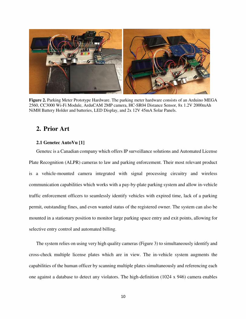
LED’s, and a camera (Figure 2). The meter is responsible for detecting a vehicle when it
approaches the parking spot and using the distance sensor in combination with colored LED’s to
tell the driver how to park. It enables a user to purchase parking using a credit card and keeps track
of the time while in a low-power sleep mode. When the purchased time expires, the meter takes a
picture of the vehicle license plate and sends to the server using the wireless module.
The more demanding task of performing the automatic license plate recognition (ALPR) is
done by the server which does not have to work under a strict power budget. If this task were to
be done locally by the parking meter, the local microcontroller would need to be capable of
handling the algorithmic complexity. However, the parking meter would still need to wirelessly

9
communicate the results of the processing to the server. Since most of the time spent by the
wireless module is actually the overhead of connecting to the access point and subsequently the
server, the bandwidth and energy savings of sending less information would be insignificant
compared to the increased energy consumption of a more powerful microcontroller. As expected,
the task of checking the appropriate databases, billing the credit card, and issuing fines is
performed by the server as well.
Figure 1. Client-Server System Architecture. The low-power parking meters placed around town are the clients.
10
Figure 2. Parking Meter Prototype Hardware. The parking meter hardware consists of an Arduino MEGA 2560, CC3000 Wi-Fi Module, ArduCAM 2MP camera, HC-SR04 Distance Sensor, 8x 1.2V 2000mAh NiMH Battery Holder and batteries, LED Display, and 2x 12V 45mA Solar Panels.
2. Prior Art
2.1 Genetec AutoVu [1]
Genetec is a Canadian company which offers IP surveillance solutions and Automated License
Plate Recognition (ALPR) cameras to law and parking enforcement. Their most relevant product
is a vehicle-mounted camera integrated with signal processing circuitry and wireless
communication capabilities which works with a pay-by-plate parking system and allow in-vehicle
traffic enforcement officers to seamlessly identify vehicles with expired time, lack of a parking
permit, outstanding fines, and even wanted status of the registered owner. The system can also be
mounted in a stationary position to monitor large parking space entry and exit points, allowing for
selective entry control and automated billing.
The system relies on using very high quality cameras (Figure 3) to simultaneously identify and
cross-check multiple license plates which are in view. The in-vehicle system augments the
capabilities of the human officer by scanning multiple plates simultaneously and referencing each
one against a database to detect any violators. The high-definition (1024 x 946) camera enables

11
plate recognition of cars parked in parallel at 45° or 90° and features integrated pulsed LED
illumination to ensure night-time performance. Wide field of view allows it to recognize plates on
all types of vehicles. The system automatically time stamps and geo tags each image and is capable
of determining vehicle travel direction, speed, and digital tire chalking, a process used to identify
vehicles parked for longer than the allotted time limit. Additionally, the system integrates with
existing Pay-by-Plate Parking technologies, eliminating the need for physical permit tags and
parking meters.
While the system is very capable and robust, it is also very expensive. The Genetec pricing
chart [2] shows that the number of components required for the whole system to run smoothly is
very large, consisting of the on-board cameras, computers, wireless units, as well expensive
software licenses. The cost of the camera alone ranges from $3000 to $7000 depending on the
package and the model which means that the system requires a significant up-front investment on
top of the continuous licensing costs. Cities may be reluctant to make such investments given the
early stage of the company’s operation in the ALPR space and the lack of data supporting the
system’s profitability. Consequently, a system such as the one being developed here offers a more
appealing alternative in that the simpler hardware is cheaper to produce and maintain, resulting in
lower barriers to replacing the existing parking meter technology while at the same time
significantly improving the efficiency of vehicle ticketing.

12
Figure 3. Genetec Vehicle-Mounted Camera. The camera is mounted on top of a parking or law enforcement vehicle and is used to scan all nearby license plates as the vehicle drives by. Scanning in multiple directions requires multiple cameras per vehicle [1].
2.2 PARKMOBILE [3]
PARKMOBILE offers a system which enables users to pay for parking via phone or phone
app. The system consists of electronic meters which, like the system at hand, are a drop-in
replacement for the medieval coin meters. Ticketing is facilitated because the system allows
officers to remotely see expired meters on a hand-held wireless device. The system does not offer
any type of automation in the ticketing process. The user has to manually enter the parking zone,
space number, and license plate while paying for parking. Officers are flagged down to expired
meters in order to manually issue tickets based on what they find on-site. The system at hand aims
to improve upon this design by automating the ticketing process so that the role of the primary cost
of operation, the enforcement officers, is reduced, thereby increasing the system’s profitability.
2.3 IPS Group, Parking & Telecommunications [4]
The IPS parking system also consists of drop-in replacement for existing single-space meters.
Optional vehicle detections is performed by a small bundle of electronics placed in the ground in

13
the designated parking space (Figure 4). The sensor communicates wirelessly with the
corresponding parking meter in order to zero the meter when the vehicle departs and inform
enforcement officers of vehicles parked in spots with expired meters, a significant improvement
over the current process of randomly looking for expired meters. The downside of this device is
the creation of a small pot hole in each parking space. Additionally, the system still relies on
enforcement officers to manually issue the ticket, making it possible for the vehicle to leave before
an officer can arrive at the scene.
Like the earlier-mentioned options, this system allows users to remotely purchase additional
parking time using a smartphone. While a remote payment system is useful, the real-time approach
at hand will also allow any future phone apps to serve the additional function of a spot finder and
a means of bidding for spots in high-demand areas. The wireless nature of the IPS system enables
real-time pricing adjustments based on parking demand. Just like the design at hand, the IPS meters
accept credit cards and are self-replenishing due to the presence of a small solar cell.
Figure 4. IPS Group Vehicle Detection Technology consisting of a sensor and transmitter that communicates with the corresponding single-space parking meter. The sensor requires a small hole in the ground of the parking space [4].

14
2.4 Relevant Patents
Numerous patents (References [5]-[20]), both valid and expired, were found that describe
systems or system elements similar to what is presented here. Most notably, the implementations
of a parking meter system with wireless communication, vehicle detection, automated payment,
available parking space location, and automated, license plate based vehicle ticketing. Although a
significant number of patents are present, many of them are not actively being utilized in a
commercially available product. A commercial implementation of the system at hand will have to
maneuver carefully within the legal landscape of parking technology. The abstracts of all the
reviewed patents are provided in Appendix A.
3. Functional Specification
3.1 Unique Vehicle Identification
The most important aspect of automating the process of ticketing vehicles is uniquely
accurately identifying a parked vehicle. In a perfect world, one would rely on the user of the
parking space to enter the license plate of the vehicle into the parking meter at the time of payment.
Unfortunately, potential dishonesty requires that a robust implementation rely on a more secure
method of extracting the necessary information. RFID transponders, such as those utilized by
highway toll systems, are a potential candidate in that many people already have a toll transponder
whose functionality can be extended to the parking system. Unfortunately, even with transponders,
there arises the possibility of users intentionally removing them from the vehicle in an attempt to
outsmart the system. Consequently, systems like highway toll collection have moved towards
utilizing cameras as the primary means of identifying and billing vehicles. It is possible that

15
vehicles of the future will all be tagged with a mandatory RFID Vehicle Identification Number
(VIN) Chip which a system like this one can utilize for accurate, automated billing.
The system at hand relies on capturing an image of the license plate in order to ticket any
parking violators. In a survey of 250 vehicles parked near curb-side parking meters in Harvard
Square in Cambridge, MA, 90% had their license plate visible in a photo taken from the perspective
of the respective parking meter. A large number of the parking spaces had white lines painted on
the ground to demarcate the boundaries of the parking space. The prototype at hand implements a
visual feedback system to help the driver correctly position the vehicle in the parking spot. This is
done in order to maximize the likelihood that a photo taken by the parking meter will contain an
optimal view of the license plate.
3.2 Wireless Communication
The core functionality of the system at hand, the capability to automatically respond to
parking violations, set parking limit and pricing dynamically, and provide real-time information
on parking availability, relies on a parking meter that is somehow connected to the internet. A
wired solution is out of the question because of the excessive fixed costs that would be incurred
by a city running cables to every parking meter on the street. Similarly, Wi-Fi is also suboptimal
as it requires the installation of routers in proximity to the parking meters. The best option at the
present time, offering a balance of cost-effectiveness and connection speed, is the cellular
network which utilizes the existing infrastructure. The parking meter prototype described here
relies on Wi-Fi simply due to the ease of testing. Since the wireless module functions
independently of all the other components, it can be easily replaced with a different technology.
16
3.3 Power
In order to function independently in the field, the electronic parking meter needs a refillable
source of energy. Many mechanical parking meters require that the user turn a knob after
depositing the coin payment. In addition to allowing the coin to be accepted, the action of turning
the knob generated energy that could be stored and used to run the time-remaining display on the
parking meter. Unfortunately, the smart parking system requires much more energy than could be
generated from one turn of the knob. Considering that most individuals would be unwilling to
consciously turn a mechanism to generate power for a device that might potentially give them a
big ticket, the most reasonable option given current technology is a combination of batteries and
solar panels.
3.4 Finding Parking and Enforcing Regulation
The functionality of finding available parking spaces, pre-purchasing parking, pricing parking
based on demand, and dynamically changing parking time limits come as a consequence of the
vehicle detection and wireless communication capabilities. Each time the parking meter connects
to the server, the server reply can include any changes to the price of parking, the time limit for
that particular spot, or whether any future times have been pre-purchased and should be held
reserved. The additional functionality relies only on additional software to handle the different
possible conditions.

17
4. Parking Meter Geometry and Architecture
4.1 Parking Space Geometry
The dimensions of a parking space are subject to local guidelines and range from 18 ft. to 22
ft. with 20 ft. being a very common middle-ground (Figure 5). Without any interference from
vehicles in adjacent sports, an average sedan of length 14.6 ft. easily fits in the parking space with
5.4 ft. of room for error. Due to that potential for error as well as possible interference from
adjacent spots, the system needs to be capable of identifying vehicles parked as far away from the
meter as 8.5 ft. and as close as 3.5 ft. (Figure 6).
Figure 5. Parking Space Geometry. The exact length of a parking space varies from 18 ft. to 22 ft. depending on the city. A 20 ft. spot was used during testing.
Figure 6. Worst-case Parking Jobs. The largest vehicle-meter distance (left) of 8.5 ft. is achieved when the vehicle is parked too far away from the parking meter. The smallest distance (right) of 3.5 ft. is achieved when the vehicle is parked too close to the meter. The angle of measurement is kept constant at 45° at both extremes.
18
4.2 Parking Meter Architecture
There are two possible ways in which cities can organize the single space parking meters. One
way is to have one parking meter per pole and one pole next to each vehicle (Figure 7). The
alternative is to mount two parking meters on each pole such that two vehicles can utilize the meter
pair (Figure 8). The second approach is less costly to install in that it requires half the poles and
half the labor to create the required post holes. However, some states do not require a license plate
to be mounted on the front of the vehicle. This excludes the electronic double meter architecture
in these states completely as each meter pair looks at the front of one vehicle and the back of the
other.
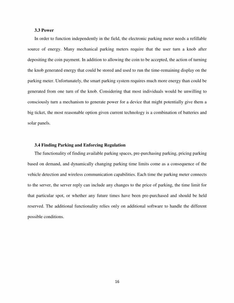
The first approach creates the potential for a hardware redundancy that allows the system
to be much more robust in the face of poorly positioned vehicles. Figure 9 shows the potential
benefit of installing two cameras per parking meter. If the vehicle is perfectly positioned in the
center of the spot, an image captured by either camera contains the license plate. If, however, the
vehicle is parked too far forward, the meter in the front of the vehicle is not able to see the license
plate. Fortunately, the meter in the back has a good view of the meter. The opposite is true when
the meter is parked too far back.
Utilizing this redundancy requires that adjacent parking meters are able to communicate
with each other. If the primary meter attempts to ticket the vehicle but the server responds with a
message indicating that a license plate was not detected, the primary meter prompts the secondary
meter to send its perspective of the vehicle to the server. Local communication hardware was
purchased but was not tested with the current system since the budget allowed for only one parking
meter prototype to be built.

19
Figure 7. Single Meter Architecture. One meter per pole, one pole per vehicle. Although this architecture requires a larger number of poles, it offers more potential for redundancies that make the system more robust – see Figure 9 [31].
Figure 8. Double Meter Architecture. Two meter per pole, one pole per two vehicles. This architecture is cheaper as it requires only half the poles of the single meter architecture. The meters are cross-coupled with the opposite vehicle in order to minimize the degree of skew in the image of the license plate [32].
20
Figure 9. Single Meter Architecture Robustness. By having two cameras per meter, each facing in the opposite direction, the single meter architecture ensures that even when the vehicle is not positioned optimally, at least one meter will be able to capture and image of the vehicle license plate.
5. Parking Meter Hardware Design and Technical Specification
5.1 Microcontroller: Arduino MEGA 2560
Since the majority of the heavy computation is done server-side, the only requirements placed
on the microcontroller are that it needs to be energy-efficient and capable of managing all the other
hardware elements. Considering the scope of the project, the Arduino MEGA 2560 was chosen as
the prototyping platform. Although very energy-inefficient, this particular microcontroller offers
a sufficient number of I/O pins and communication busses to handle all of the external hardware
connections. While a microprocessor like the ARM Cortex-M0+, utilizing only 11.2µW/MHz is
much more fitting for a commercial product, it does not offer the same ease of prototyping as the
Arduino platform [29]. Consequently, the Arduino was chosen in order to take advantage of the
more mature prototyping platform.

21
5.2 Wireless Module: TI CC3000
The TI CC3000 was selected for the wireless module. The chip offers an integrated Wi-Fi
solution with an embedded TCP/IP stack. The CC3000 communicates with the microcontroller via
the SPI bus and adheres to the 802.11 b/g IEEE standard and supports open, WEP, WPA, and
WPA2 security. The module operates at 3.6V and is said to draw between 190mA and 260mA
while transmitting and 92mA while receiving. It has a shut-down mode which draws only 5µA,
making it a good candidate for the low-power setting.
5.3 Distance Sensor and Driver Feedback: HC-SR04
Based on the worst case parking vehicle-meter parking range described in Figure 6, the HC-
SR04 ultrasonic distance sensor was chosen. It offers a range of 2 cm to 400 cm which offers a
margin for error above the required 100 cm to 260 cm required by the parking geometry. The
sensor is inexpensive at under $2.00 per unit with further discounts for bulk purchase.
Additionally, its low power requirement of only up to 75 mW means that it can be powered from
a digital I/O pin on the microcontroller and therefore can be very efficiently turned on and off as
required.
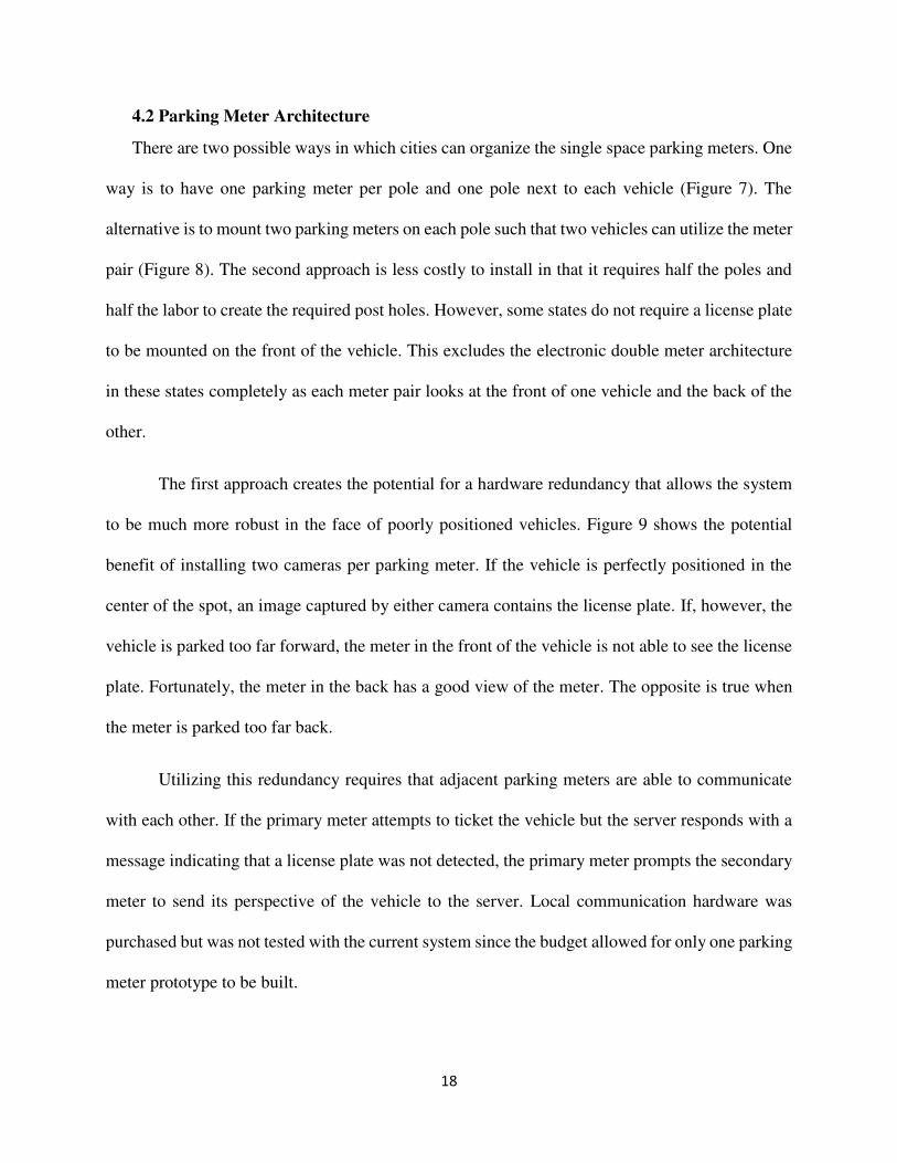
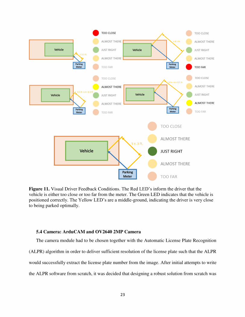
The information provided by the distance sensor is conveyed to the driver using a set of 5
LED’s (Figure 10). As the driver pulls in to the parking space, the meter detects a change in
distance and begins offering feedback (Figure 11). If the vehicle is further from the meter than 8.5
ft., the top red LED lights up. If the vehicle is closer than 3.5 ft., the bottom LED lights up. Optimal
vehicle positioning corresponds to a distance between 4 ft. and 6 ft. The yellow LED’s indicate a
middle-ground between being positioned perfectly and completely incorrectly. The initial design
22
consisted of only three LED’s with the red and yellow duplicates merged. This design had the
potential to be unclear in the case where the driver was “almost there”.
While the prototype relies only on visual feedback, future versions can take advantage of the
increasing developments in the Internet of Things (IoT) and potentially communicate with the
vehicle on-board computer to offer feedback, either visual or audible, directly in the vehicle.
Figure 10. Visual Driver Feedback. Five LED’s are used in combination with the output of the distance sensor to inform the driver of any error in vehicle positioning. The distance feedback is activated when the meter detects a vehicle approaching the parking space via the distance sensor output.
23
Figure 11. Visual Driver Feedback Conditions. The Red LED’s inform the driver that the vehicle is either too close or too far from the meter. The Green LED indicates that the vehicle is positioned correctly. The Yellow LED’s are a middle-ground, indicating the driver is very close to being parked optimally.
5.4 Camera: ArduCAM and OV2640 2MP Camera
The camera module had to be chosen together with the Automatic License Plate Recognition
(ALPR) algorithm in order to deliver sufficient resolution of the license plate such that the ALPR
would successfully extract the license plate number from the image. After initial attempts to write
the ALPR software from scratch, it was decided that designing a robust solution from scratch was

24
out of the scope of the project. Consequently, the open-source OpenALPR software based on the
Open Computer Vision (OpenCV) library was selected for the prototype.
OpenALPR is broken down into 8 pipelined stages that operate on the input image to produce
an ASCII output representing the best approximation of the license plate number present in the
image. The first stage consists of detecting possible license plate regions using the LBP algorithm.
Each possible license plate regions is then sent through multiple binarizations in order to account
for images that are too light or too dark. Each binarizations is then processed for successively
larger character blobs. Images with no possible characters found are thrown out. Images containing
characters undergo plate edge detection followed by a deskew process to normalize the image
perspective to a head-on view. The possible characters in the image are then segmented and
undergo Optical Character Recognition (OCR). Finally, the algorithm combines all the processing
results and presents a top N list of results, where N can be specified by the user. One can also
specify parameters such as the state origin of the license plate in which case the algorithm will
attempt to match the output against the particular state’s license plate template. For example, a
Missouri license plate follows a character, character, number – character, number, character plate
format [30].
Since the algorithm documentation does not specify a minimum required resolution for the
license plate region, this was determined experimentally in the following manner. Ten vehicle
images were taken from the perspective of a parking meter using an iPhone 6. The images were of
vehicles parked correctly based on the previously defined parking geometry. The images were
successively downsized and tested with OpenALPR until the algorithm failed to detect the license
plate. The license plate area of the smallest successful image was measured using picresize.com.
OpenALPR successfully extracted the license plate number from all the images at full resolution.
25
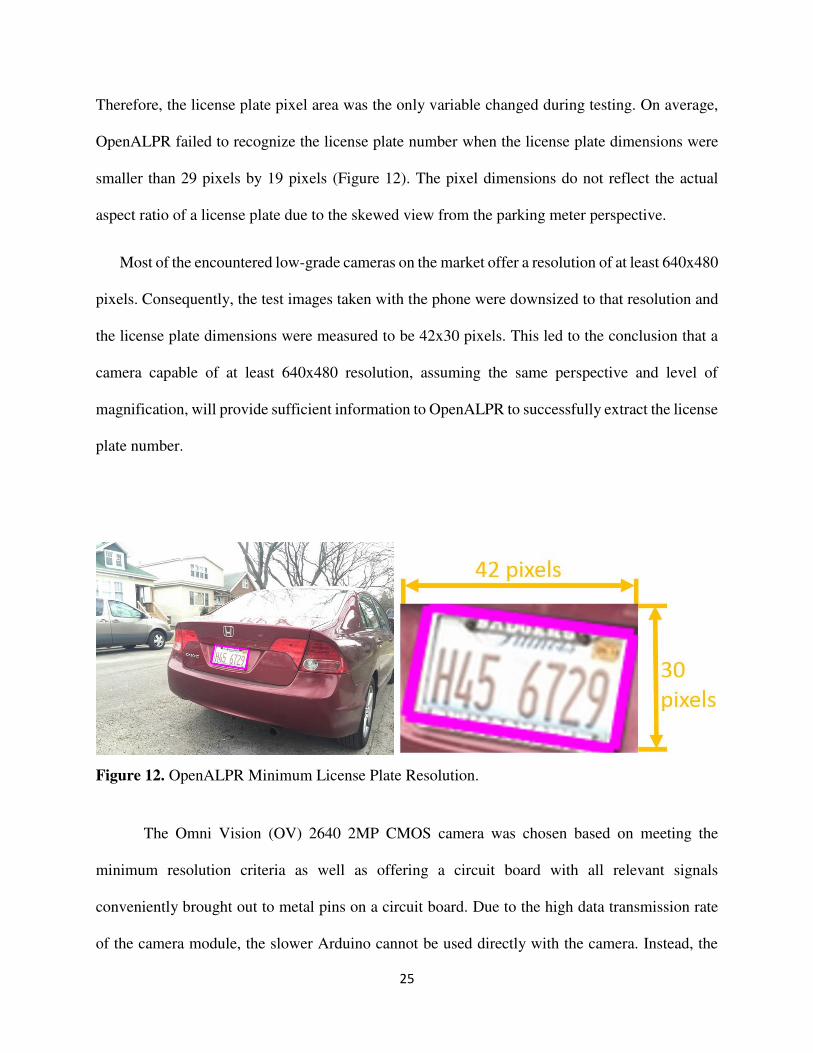
Therefore, the license plate pixel area was the only variable changed during testing. On average,
OpenALPR failed to recognize the license plate number when the license plate dimensions were
smaller than 29 pixels by 19 pixels (Figure 12). The pixel dimensions do not reflect the actual
aspect ratio of a license plate due to the skewed view from the parking meter perspective.
Most of the encountered low-grade cameras on the market offer a resolution of at least 640x480
pixels. Consequently, the test images taken with the phone were downsized to that resolution and
the license plate dimensions were measured to be 42x30 pixels. This led to the conclusion that a
camera capable of at least 640x480 resolution, assuming the same perspective and level of
magnification, will provide sufficient information to OpenALPR to successfully extract the license
plate number.
Figure 12. OpenALPR Minimum License Plate Resolution.
The Omni Vision (OV) 2640 2MP CMOS camera was chosen based on meeting the
minimum resolution criteria as well as offering a circuit board with all relevant signals
conveniently brought out to metal pins on a circuit board. Due to the high data transmission rate
of the camera module, the slower Arduino cannot be used directly with the camera. Instead, the

26
ArduCAM FPGA-based board is used to read, compress, and buffer the image data. ArduCAM
communicates with the Arduino via SPI and I2C and outputs the file in JPEG format which
decreases the amount of data that has to be sent back to the server. The board also contains a micro-
SD card which can be used to store violator information in case the meter loses network
connectivity.
5.5 User Interface
The system prototype was given a basic user interface with 2 push buttons and a RioRand 4
line, 20 character LCD display based on the HD44780 controller. The buttons allow a user to scroll
through a sample menu system. The LCD is not an integral part of the system prototype design
and was implemented only to give the system the “feel” of an actual parking meter. The LCD is
useful in that it’s measured energy consumption factors into the power budget for the parking
meter.
5.6 Solar Panels: 2x 12V 45mA
The energy consumption of all the listed components was measured individually using a Texas
Instruments INA219 High-Side current monitor. Voltage and current data was relayed from the
sensor to an Arduino UNO which sent the data via USB to a PC running MATLAB 2014b for data
logging and graphing. The power consumption of each hardware element was measured
individually while performing its essential duties within the larger system. The average power was
computed using MATLAB. Plots of the data are available in Appendix D.
A power budget was created based on a meter usage frequency of two vehicles per hour and
an active billing period of 10 hours; people are required to pay for curb-side parking between the

27
hours of 8 am and 6 pm. The duration of use of each hardware peripheral was estimated based on
the time limits set in the software (see section 6.1) as well as the anticipated frequency and duration
of use. For example, the distance feedback consisting of the HC-SR04 and the 5 LED’s is used for
a maximum period of 5 minutes per vehicle. Since it is estimated that each meter will service 20
vehicles per day, the distance feedback module will be in active use for approximately 1.66 hours,
using a total of 58 mWh based on an average power consumption of 35 mW. The data for the
remaining modules is shown in Figure 13.
The total energy consumption of the system totals to 12 Wh/day. In order to get a better sense
of the magnitude of this number, it can be compared to the energy storage capabilities and power
requirements of modern phones. The iPhone 6 battery can store 6.91 Wh [26] and Apple claims
that a user can browse the internet via 3G or LTE network for up to 10 hours [27]. It can be seen
from Figure 13 that the Arduino MEGA 2560 is the primary cause of the large energy
consumption. While the board is great for prototyping and debugging, the inefficient voltage
regulators and always-on indicator LED’s burn excessive power. Running the same code with a
bare-bones ATEGA328P such as the one found in the Arduino UNO, the energy requirement drops
considerably due to the removal of the wasteful elements. Ideally, the final design will utilize a
modern processor which takes advantage of more efficient architectures and more advanced
fabrication technologies. One such candidate is the ARM Cortex-M0+ which cuts the system
energy consumption to only 470 mWh/day. Putting that in perspective, with the Cortex-M0+ in
place, the system is estimated to run on an iPhone 6 battery for almost 15 days.
Based on this power requirement approximation and the spatial constraints of a single-space
parking meter, one can being to select solar panels for the system based on the expected sunshine
in a given location. The worst-case in the US is represented by the city of Seattle, WA which boasts

28
the title of the fourth US city with a population above 50,000 people with the lowest percentage
of sunlight between sunrise and sunset at 37.3%. For comparison, Chicago comes in at 53.5% [24].
In the month of December, Seattle receives and average of 1.02 kWh/m2 per day in the month of
December and represents the worst-case conditions in the continental US [25]. The annual average
for Seattle is 3.74 kWh/݉2/day [25]. A solar panel with a peak output of 1W at an irradiance of 1
kW/m2 will generate 1 Wh in the course of an hour. Therefore, based on the average irradiance in
Seattle in December, that same solar panel will generate approximately 1 Wh. While there will be
some variation due to temperature and the specific location of the solar panel, this provides a good
approximation of the power budget.
Based on the calculations, two 12 V 45mA solar panels were selected for the prototype. The
panels are capable of generating about 1.08 Wh per day in winter-time Seattle which provides a
safety factor greater than two above the estimated power consumption of 470 mWh/day. The
panels are wired in parallel which results in a total peak output of 12 V and 90 mA. Each panel is
protected with a backflow diode. The solar panel will ultimately need to be custom tailored to the
geographical location of the city in which the parking system is being utilized; sunny Florida gets
four times the average daily irradiance of Seattle [25] and will therefore be able to function on less
than one of these solar panels.
29
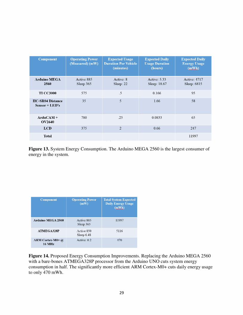
Figure 13. System Energy Consumption. The Arduino MEGA 2560 is the largest consumer of energy in the system.
Figure 14. Proposed Energy Consumption Improvements. Replacing the Arduino MEGA 2560 with a bare-bones ATMEGA328P processor from the Arduino UNO cuts system energy consumption in half. The significantly more efficient ARM Cortex-M0+ cuts daily energy usage to only 470 mWh.

30
5.7 Batteries: 8x 1.2 V 2000 mAh NiMH
The battery system is capable of storing up to 19.2 Wh of energy which translates into a 40
day backup for the most efficient design utilizing the Cortex-M0+. In the worst-case of December
in Seattle, the batteries hold the energy that one expects to be generated over the course of 17 days.
NiMH batteries were chosen because they are rechargeable and do not require the overhead of the
balancing circuitry. Lithium Polymer are the primary choice in modern electronics due to their
energy density. However, since the parking meter is nowhere nearly as space-constrained as a
phone, the easier to work with NiMH batteries were utilized in the prototype. Once again, as with
the solar panels, the actual battery capacity will be chosen based on the particular city choosing to
take advantage of the system.
Figure 15. System Hardware Block Diagram.

31
6. Software Control Flow
6.1 Parking Meter Control Flow
The block diagram in Figure 16 represents the control flow of the local meter software in a
zone without any limits on the amount of time a vehicle can be parked. The meter starts in the
powered-down sleep state in which it does nothing in order to conserve power. Upon arrival of a
vehicle, the microcontroller wakes up and starts a timer. This timer ensures the proper behavior of
the state machine by giving the driver enough time to properly park the vehicle. At this time, the
distance sensor and LED provide feedback to the driver so that he or she positions the car correctly
relative to the meter. Additional time is added if the driver continues moving in order to account
for poor parking skills. Motion is detected via measurable changes in the reading from the distance
sensor. There is a maximum limit of 10 minutes on this timer to prevent users from taking
advantage of the system by repositioning their car slightly so as to keep the meter in this state.
This, and all other time limits, are easily adjustable and can be tailored to the demands of the city
via simple software modifications.
If the user parks correctly and no motion is detected, the meter starts a second timer and waits
for payment. Should the user not park optimally, the meter takes a picture, sends it off-site, and
proceeds to the Pay state in the same manner as if the user parked correctly. Since there is no limit
on how long the vehicle can be parked, the meter does not actually need to take any action unless
the time expires. The picture is taken because even if the vehicle is not positioned optimally, the
license plate can still perhaps be extracted. If the license plate cannot be extracted using ALPR or
manual LPR (visual inspection by a human), the system can dispatch any idle parking enforcement
officers to the vehicle location so that they can identify the vehicle manually and log that
information into the system. As a result, idle parking officers are utilized and the system ensures

32
that when the time does expire, it can still ticket that vehicle. This also allows the system to send
a warning email to the vehicle owner and ask for future compliance, the lack of which might incur
a small penalty.
The meter gives the vehicle operator 4 minutes to administer payment. If payment is not
administered in time, the vehicle is ticketed. The city can choose the amount of this fine and
whether it is administered as a one-time charge or an elevated per unit time fee. At this time, this
is a one-time fine equivalent to the expired meter fine. If payment is administered in time, the
meter starts the final timer, reflecting the amount of time purchased by the user, and returns to the
sleep state. If this timer expires before the vehicle departs, the meter takes a picture of the vehicle
and sends it to the server for ALPR. The server then handles the vehicle identification and billing.
The block diagram in Figure 17 represents the control flow of the local meter software in a
zone with limits on the amount of time a vehicle can be parked. The main difference is that now
the local meter must capture an image as soon as the vehicle parks in order to find out whether the
vehicle has been parked in any nearby time-limited zones. The system needs to ensure that
someone cannot simply move their vehicle to a different spot in the same general area and violate
the time limit that way. The server must check the vehicle’s parking history and determine whether
the vehicle has been parked in a given radius of the meter it is attempting to use in the past several
hours. The server then determines a time limit for that vehicle and communicates that information
back to the meter.
If a given vehicle parks in a 2 hour time limit zone for 1.5 hours, leaves that space, and attempts
to park within a restricted zone (set by the city) at some point later on the same day, the server tells
the meter to only allow the user to add a maximum of 30 minutes to the meter. Cities also have the
option of charging a premium for any additional time above the established time limit. Cities can

33
chose to have time limits hard coded into meters or have them dynamically updated each time the
meter contacts the server. The prototype meter is following the unlimited time protocol.
Figure 16. Local Control Flow, No Time Limit. As a vehicle arrives, the meter offers feedback to the driver, awaits payment, and keeps track of the purchased time. The meter tickets the vehicle when time runs out.

34
Figure 17. Local Control Flow, With Time Limit. The meter must now ensure the vehicle has not previously parked in a time-limited zone nearby.
6.2 Server Control Flow
The block diagram in Figure 18 represents the control flow of the server-side software in
response to a meter request. The system starts in an idle state listening for HTTP requests from
parking meters. The meter presents a Meter Number and a Password sent via a POST request as a
means of authenticating itself. The request also includes a status code which designates the event
that the meter is trying to communicate to the server. The meter can communicate that a vehicle is
to be ticketed, a vehicle is incorrectly parked, or request info about any parking time limits in effect
for that particular meter.

35
In the case of an incorrectly parked vehicle, the meter will preemptively send a request to
identify the vehicle based on the acquired image. Although the vehicle is not in violation of any
law, its incorrect positioning may mean that when it comes time to ticket the vehicle, the license
plate will not be visible in the captured images. In this case the control flow has only one possible
path to take. The image received from the meter undergoes Automatic License Plate Recognition
(ALPR). Should the ALPR fail, the image is presented to a human for visual inspection and
extraction of the license plate. Should the license plate not be visible in the image, an on-foot
officer is dispatched to the vehicle location to identify the vehicle license plate. The highest order
stage to successfully extract the license plate information ends the License Plate Recognition
(LPR) chain.
In the case of a parking violation, the meter sends an image with the corresponding status code.
If the vehicle had been incorrectly parked, it is very likely that the preemptive ALP process
described in the preceding paragraph has already identified the license plate. In this case, the
vehicle can be ticketed directly. If the vehicle has been correctly positioned, the received image
will presumably be identifiable by either the ALPR or the manual LPR stage at which point the
vehicle can be appropriately ticketed. Should ALPR and manual LPR be unsuccessful, an on-foot
officer will be dispatched to the vehicle location to manually issue the ticket. If the on-foot officer
arrives before the vehicle departs, the officer can provide the license plate information to the server
using a hand-held wireless device along with photographic evidence of the car’s presence. The on-
foot officer interface is implemented as a web page in the prototype and can be effectively used
with any web-enabled smartphone. The interface prioritizes ticketing requests over preemptive
vehicle identification requests because ticketing requests are more profitable for the city.

36
The optimal single meter architecture discussed in section 4.2 is not utilized in the control flow
presented here. A final product utilizing the single space architecture would have an additional
step between the ALPR and Manual LPR stage. Namely, should the server fail to extract a license
plate from a particular image, it would inform the parking meter of the event. That parking meter
would then prompt the secondary meter to capture an image of the vehicle and send it to the server
for analysis. Considering the evidence in section 4.2, this second image is expected to be
successfully utilized by the ALPR. Only if both images fail will they be forwarded to a human for
analysis and potentially require the involvement of an on-foot officer. The layers of redundancy
are offered in order to minimize the amount of people required to service the city’s parking system
and therefore decrease the operating cost of the department.
Figure 18. Server-Side Control Flow. The server contains three layers of redundancy in identifying vehicle license plates.

37
7. Testing
7.1 Driver Feedback
The parking space geometry outlined in Figure 5 was reproduced in a residential area of
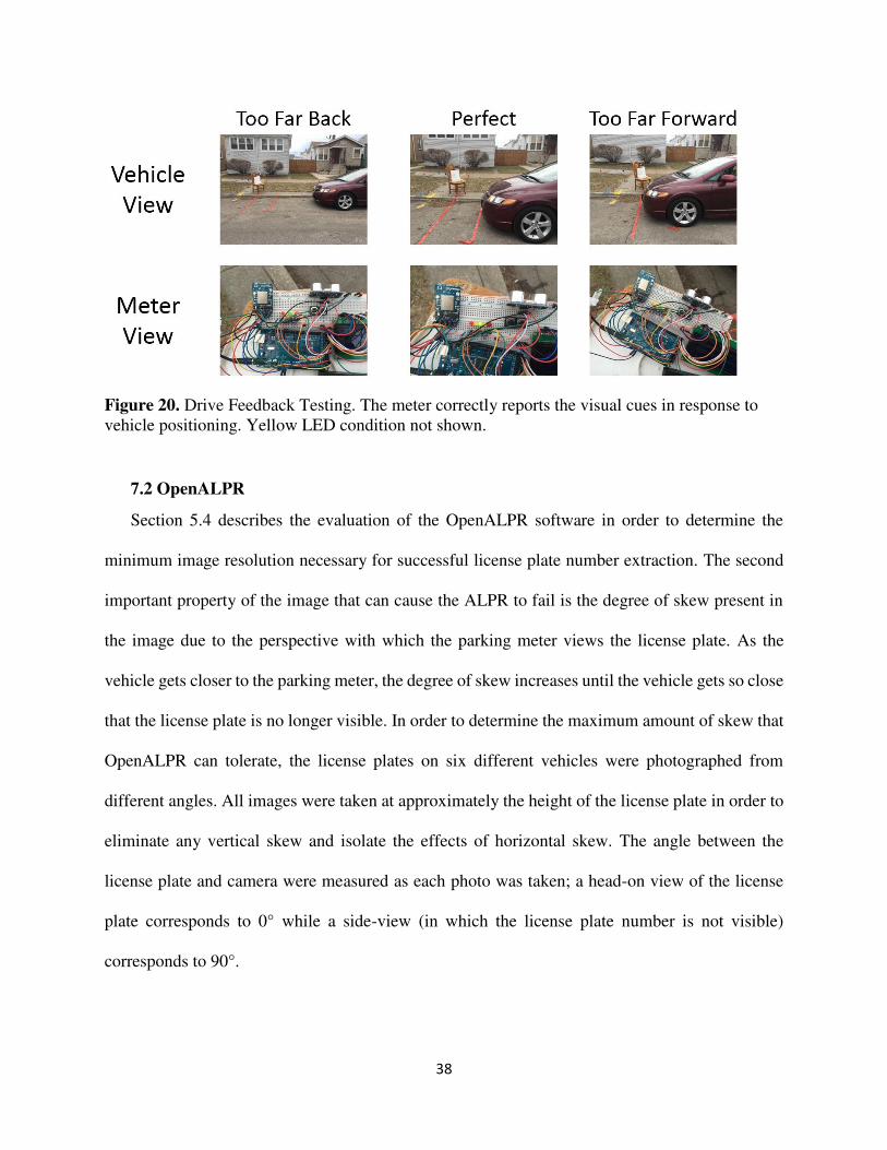
Chicago (Figure 19) in order to test the efficiency of the distance feedback system. The system
hardware was placed on top of a chair and bucket in order to replicate the height of an actual
parking meter (Figure 20). Five licensed drivers with at least 2 years driving experience were asked
to park their own vehicle in response to the visual cues provided by the parking meters. All were
informed that the bundle of electronics represents a new parking system installed by the city that
is smart enough to tell you where to park your vehicle but were not told how the meter
accomplishes this task.
All drivers were correctly able to interpret that the LED’s change color in response to how
close the vehicle is to the parking meter. While all five drivers were able to park correctly, all
complained that the LED’s are very had to see and need to be bigger and brighter. While larger
LED’s will use more energy, the increased level of compliance on the part of the drivers should
be worth the energetic cost in a final design.
Figure 19. Driver Feedback Testing Set-Up. The vehicle is optimally positioned for ALPR. The prototype parking meter is placed in the spot designated by the red X in the first image.
38
Figure 20. Drive Feedback Testing. The meter correctly reports the visual cues in response to vehicle positioning. Yellow LED condition not shown.
7.2 OpenALPR
Section 5.4 describes the evaluation of the OpenALPR software in order to determine the
minimum image resolution necessary for successful license plate number extraction. The second
important property of the image that can cause the ALPR to fail is the degree of skew present in
the image due to the perspective with which the parking meter views the license plate. As the
vehicle gets closer to the parking meter, the degree of skew increases until the vehicle gets so close
that the license plate is no longer visible. In order to determine the maximum amount of skew that
OpenALPR can tolerate, the license plates on six different vehicles were photographed from
different angles. All images were taken at approximately the height of the license plate in order to
eliminate any vertical skew and isolate the effects of horizontal skew. The angle between the
license plate and camera were measured as each photo was taken; a head-on view of the license
plate corresponds to 0° while a side-view (in which the license plate number is not visible)
corresponds to 90°.

39
Testing revealed that, on average, OpenALPR fails to correctly recognize the license plate
number when the degree of perspective skew exceeds 55°. The results range from a low of 49° to
a high of 61° potentially accounted for by variations in lighting and license plate wear and tear.
While the single meter architecture described in section 4.2 can easily deal with this shortcoming,
improvements to OpenALPR can eliminate the extra power usage that takes place when the
redundant architecture is utilized.
Figure 21. OpenALPR Evaluation. On average, the algorithm can tolerate up to 55° of perspective skew between the surface of the license plate and the camera.
7.3 System-Level Performance
In addition to analyzing OpenALPR independently, the performance of the whole system
was evaluated using printouts of license plates and vehicles with visible license plates in order to
verify that that the system can accomplish the task of automated ticketing. Figure 22 shows the
output of the two most recent tests presented through the E-Park web interface. 14 out of the 15
tests performed on the system successfully resulted in the correct extraction of the license plate
when the license plate region met the minimum required resolution and the degree of skew in the

40
view of the license plate was no greater than 55°. In the failed trail, the system correctly found
the license plate but the reported number was incorrect; an additional character was present in
the extracted sequence.
Figure 22. System Performance Testing. The parking meter is successfully able to capture an image, connect to a Wi-Fi access point, and send the photo to the server. The figure shows the web interface displaying the successful results of the latest tests.

41
8. Conclusion
8.1 Financial Impact: Cambridge
A preliminary profitability analysis was conducted for the city of Cambridge based on the
2013 fiscal year information [21]. The parking system should be attractive to cities for two
reasons. One, it offers cost saving by decreasing the number of parking enforcement officers that
the city must employ. Second, the device will increase the revenue streams from parking fees
and parking tickets by introducing real-time response to the meter balance.
On the cost side, the city of Cambridge currently employs 33 parking officers. Each
employee costs the city a salary of about $38,000 on top of any other benefits provided by a city
job [22]. A successful meter implementation would be able to repurpose 30 of the 33
enforcement officers, totaling a savings of about $1.2M per year for the department. It is
necessary to keep some officers on staff so that they may be flagged down by the meter in
situations that the meter cannot handle automatically. This represents a 5% decrease in the
operating costs of the Cambridge Traffic and Parking Department.
On the revenue side, parking fines currently bring in $10M and 80% of all fines are for
expired parking meters [22]. If we assume that only about 75% of violators are successfully
ticketed, the city is missing about $2.5M in revenue each year. Meter collections total about
4.5M annually and, based on a survey of Cambridge parking only 80% of the fees are actually
being collected due to undetected violations. Therefore, the city is missing about $1.125M in
revenue annually [22]. Assuming the automated meter would be very close to catching all
violators, the system is worth between $2.7M and $3.625M to the City of Cambridge each year.
If we instead assume that the $1.125M uncollected fees all turn into fines, meaning what would
have been $0.25 parking fee becomes a $25 fine, the estimated value of new fines skyrockets to

42
$112.5M. This extreme estimate assumes that people would not change their parking habits in
response to the new meters. In reality, individuals would be more cautious about parking.
Therefore, the actual value of the system falls somewhere in between the two estimates.
Cambridge currently has 3,121 parking meters [22]. With a payback on investment period of
1 year, Cambridge could afford to buy each meter at $800-$1200, not considering the initial
fixed cost of installing new meters and assuming the more conservative valuation model. The
fixed cost of meter installation will vary by city. Cities with existing single-space meters will
incur the lowest cost as meter installation will consist of a drop-in replacement onto existing
poles. Additional costs may result if existing poles are not up-right or are not placed properly for
vehicle detection. On the high end, cities will need to install the poles on which the system is
mounted from scratch. Fixed costs may also come from the need to install Wi-Fi nodes if a
particular city does not want the meters to rely on the cellular network.
If the meter could be mass produced, all the electronics would cost well under $100. A secure
casing could be manufactured within $200 based on the cost of existing single space parking
meters [28]. Based on this initial analysis, the margins for bringing an auto-ticketing parking
meter to market are very favorable. Additionally, there is no shortage of cities around the world
that could benefit from a system like this. The predicted revenue increase of 20-30%, as
estimated above, is consistent with what the IPS Group predicts for its parking meters [23]. The
IPS Group, a major electronic parking meter manufacturer, predicted a 10-30% increase in
revenue for the city of San Francisco as a result of installing new single-space solar powered
parking meters which accept credit cards and coins and are capable of flagging officers to
expired parking meters [23]. Considering that this system will have a much faster response time

43
and will decrease the need for parking enforcement officers, the 20-30% revenue boost is a rather
conservative estimate.
8.2 Future Work
The work presented here is proof of the feasibility of implementing a modern electronic
parking system that automatically fines violators, operates independently of a wired power
source, and minimizes the need for human intervention in the parking management process. In
order to bring the project closer to commercial deployment, the project requires several
adjustment, some of which were already mentioned in the course of the paper. First, the
inefficient Arduino MEGA 2560 needs to be upgraded to a more energy efficient processor like
the ARM Cortex-M0+. Second, all the hardware peripherals such as the camera and Wi-Fi
module need to be powered from more efficient voltage regulators that include a shut-down
capability. This will allow all the microcontroller to selectively deliver power to only the
peripherals currently being utilized. The power budget discussed in section 5.6 assumes
negligible power consumption in all the hardware peripherals while they are not being utilized.
While many of them already have a low-power shut-down state, more efficient voltage regulators
like the LT-1529 can but that sleep-mode energy usage even further.
Furthermore, additional prototypes need to be built in order to test the inter-meter
communication and assess the effectiveness of the single meter architecture redundancy. The
prototype also requires the touch of a mechanical engineer in designing a housing. The
electronics of the prototype are the beautiful princess disguised as an ugly frog; they need the
kiss of the mechanical engineering prince to bring out their true potential so that the design
beings to look like an actual parking meter.

44
9. References
[1] Genetec, 'AutoVu Automatic License Plate Recognition | Genetec', 2014. [Online]. Available: http://www.genetec.com/solutions/all-products/autovu. [Accessed: 26- Sep- 2014]. [2] PEPPM. Technology Bidding and Purchasing Program, 'Pricelist Template Form', 2015. [Online]. Available: http://www.peppm.org/Products/genetec/price.pdf. [Accessed: 03- Jan- 2015]. [3] Cityofnewhaven.com, 'Welcome to the New Haven Department of Transportation, Traffic and Parking', 2015. [Online]. Available: http://www.cityofnewhaven.com/TrafficParking/parkmobile.asp. [Accessed: 29- Sep- 2014]. [4] Ipsgroupinc.com, 'IPS Group, Inc. SINGLE-SPACE METERS', 2015. [Online]. Available: http://www.ipsgroupinc.com/products/single-space-meters.htm. [Accessed: 14- Oct- 2014]. [5] J. P. Jacobs and V. G. Yost, “Electronic parking meter,” U.S. Patent 619 501 5 B1, February, 2, 1999. [6] Y. Katz, “Parking status control system and method,” U.S. Patent 655 977 6 B2, November, 14, 2001. [7] R. R. Vincent, “Web-based systems and methods for internet communication of substantially real-time parking data,” U.S. Patent 694 697 4 B1, May, 13, 2004. [8] F. L. Mitschele, “Parking meter,” U.S. Patent 702 916 7 B1, September, 27, 1999. [9] C. K. Howard, K. Cayetano, O. Omojola, “Parking management systems,” U.S. Patent 739 133 9 B2, April, 25, 2005. [10] G. E. Chauvin, N. S. Erksine, G. A. Kackay, “Data collection system for electronic parking meters,” U.S. Patent 833 928 1 B2, April, 24, 2012. [11] M. Rosen, “Method and system for automated detection of mobile phone usage,” U.S. Patent 838 455 5 B2, January, 11, 2010. [12] D. W. King, A. Schwarz, “Coin validation unit with clip feature,” U.S. Patent 847 990 9 B2, March, 31, 2008. [13] S. J. Hunter, A. M. Joubert, “Power supply unit,” U.S. Patent 851 383 2 B2, March, 31, 2008. [14] D. King, D. K. Hunter, M. J. Hall, D. A. Jones, “Parking meter,” U.S. Patent 859 068 7 B2, December, 20, 2010.
45
[15] D. W. King, A. Schwarz, “Parking meter and a device therefor,” U.S. Patent 859 505 4 B2, December, 4, 2006. [16] D. W. King, C. P. Randall, “Parking meter communication for remote payment with updated display,” U.S. Patent 874 940 3 B2, September, 3, 2010. [17] W. E. Long, “Parking violation recording system and method” U.S. Patent 738 228 0 B2, October, 17, 2005. [18] E. L. Sneed, K. K. Sneed, “Wireless parking meter” European Patent 098 005 5 A1, July, 6, 1999. [19] A. Schwarz, A. J. Hunter, “Low Power Vehicle Detection” U.S. Patent 201 300 272 18 A1, July, 25, 2012. [20] D. W. King, A. Schwarz, S. J. Hunter, “Method and apparatus for automatic location-specific configuration management of a removable meter unit” U.S. Patent 200 901 839 66 A1, January, 16, 2009. [21] Cambridgema.gov, 'Budget Department - City of Cambridge, Massachusetts', 2015. [Online]. Available: http://www.cambridgema.gov/budget.aspx. [Accessed: 10- Oct- 2014]. [22] Lawenforcementedu.net, 'Parking Enforcement Officer Jobs and Salary', 2015. [Online]. Available: http://www.lawenforcementedu.net/parking-enforcement-officer/. [Accessed: 08- Oct- 2014]. [23] Yoursolarlink.com, 'San Diego Testing Solar Powered Parking Meters. Your Solar Link Blog', 2015. [Online]. Available: http://www.yoursolarlink.com/blog/san-diego-testing-solar-powered-parking-meters/. [Accessed: 15- Oct- 2014]. [24] City-data.com, 'Top 101 cities with the lowest average sunshine amount (population 50,000+)', 2015. [Online]. Available: http://www.city-data.com/top2/c475.html. [Accessed: 14- Oct- 2014]. [25] Pvwatts.nrel.gov, 'PVWatts Calculator', 2015. [Online]. Available: http://pvwatts.nrel.gov/index.php. [Accessed: 31- Oct- 2014]. [26] W. Rothman, 'Teardowns of iPhone 6 and iPhone 6 Plus Reveal Big Battery Difference', WSJ, 2015. [Online]. Available: http://blogs.wsj.com/personal-technology/2014/09/19/teardowns-of-iphone-6-and-iphone-6-plus-reveal-big-battery-difference/. [Accessed: 03- Nov- 2014]. [27] Apple, 'Apple - iPhone 6 - Technical Specifications', 2015. [Online]. Available: https://www.apple.com/iphone-6/specs/. [Accessed: 03- Nov- 2014].
46
[28] Nelson/Nygaard, 'TECHNICAL MEMORANDUM #5: TECHNOLOGY', 2015. [Online]. Available: http://www.concordma.gov/pages/ConcordMA_Planning/Concord_Technology_FINAL.pdf. [Accessed: 14- Nov- 2014]. [29] Arm.com, 'Cortex-M0+ Processor - ARM', 2015. [Online]. Available: http://www.arm.com/products/processors/cortex-m/cortex-m0plus.php. [Accessed: 05- Mar- 2015]. [30] GitHub, 'openalpr/openalpr', 2014. [Online]. Available: https://github.com/openalpr/openalpr/wiki/OpenALPR-Design. [Accessed: 01- Mar- 2015]. [31] Davethepa.buzznet.com, 'Parking Meter', 2015. [Online]. Available: http://davethepa.buzznet.com/photos/default/?id=23295121. [Accessed: 03- Mar- 2015]. [32] Fringecollective.com, 'Fringe Collective - News from the Fringe - 5.15.12', 2015. [Online]. Available: http://fringecollective.com/blogposts/201_/5.15.12.html. [Accessed: 02- Mar- 2015].

47
A. Patent Review Abstracts
A.1 Electronic Parking Meter Patent – EXPIRED [5]
An electronic parking meter which is capable of detecting presence of a parked vehicle, keeping
track of the amount of money, including both U.S. and foreign coinage, in the meter, gathering
statistics on the parking space and the meter, alerting the parking authority of meters that are
expired in connection with vehicles still parked, and zeroing the remaining time off of any meter
once the parked vehicle departs.
A.2 Parking status control system and method – EXPIRED [6]
A parking status control system and method allow a parking space, or plurality of parking
spaces, to be automatically monitored to detect unauthorized occupancy. The system and method
may be applied to metered parking spaces or to other situations where controlled access to a
parking space or area is desired. The presence or lack of a vehicle in a monitored parking space
is determined using a vehicle presence detector, which communicates a signal indicative of such
presence to a central system. A user or vehicle based authorization module is configured to
transmit an authorization input to facilitate automated satisfaction of a space authorization
device, e.g., payment of a parking meter. If there is occupancy, but no proper authorization input,
the central system declares a violation and communicates the violation to another system or
individual charged with taking corrective action.
A.3 Web-based systems and methods for internet communication of substantially real-time
parking data – VALID [7]
A parking system includes an internet-accessible Web server storing substantially real-time
parking data associated with occupancy of a plurality of parking spaces. The parking data can be
rendered by a display device running a browser application. The Web server transmits the
parking data in response to a request sent from the browser application. The Web server
communicates with at least one of a detector and a parking terminal configured to collect and
transmit parking data.
A.4 Parking meter using camera to detect the presence of a vehicle – VALID [8]
A parking meter includes a microcontroller and a timer coupled with a microcontroller. A
mechanism for accepting payment by coin, credit card or both is coupled with the
microcontroller for accepting payment for use of an associated parking space. The
microcontroller initiates the timer for a prepaid parking interval upon receiving a signal from the
payment acceptance mechanism. A vehicle detector is coupled with the microcontroller for
detecting the presence or absence of a vehicle in the associated parking space. The
microcontroller initiates an interrogation station to direct an interrogation signal at the associated

48
parking space in the area of the parking space where the license plate of a parked vehicle is
located upon determining the existence of a parking violation.
A.5 Parking management systems – VALID [9]
The systems described herein include one or more wireless vehicle detectors, along with a
distributed parking payment system such as parking meters or a pay station. Information from
the payment system and the vehicle detectors may be combined to determine when a parking
violation occurs, or is about to occur. This information may then be transmitted through a
communication system to a parking enforcement officer, along with information about the
geographic location of the violation. The information may also, or instead be transmitted to a
parking payer to notify the payer of an impending infraction so that the payer may purchase
additional parking time before the violation.
A.6 Data collection system for electronic parking meters – VALID [10]
There is disclosed a single space parking meter that includes a low powered radio for
communicating with a mobile access point. There is also provided a parking meter management
system comprising a single space parking meter and a mobile access point. The mobile access
point comprises a coin collection cart, and a mobile data collection terminal including a wireless
radio for communicating with the wireless radio of the single space parking meter. Also
disclosed is a method of managing single space parking meters comprising the steps of collecting
and storing meter information in a single space parking meter, receiving at a main electronics
board of the single space parking meter a transmit signal, and transmitting the meter information
to a mobile access point using a low powered radio of the single space parking meter.
A.7 Method and system for automated detection of mobile phone usage – VALID [11]
A method and apparatus for automated detection of mobile phone usage by drivers of vehicles
includes at least one mobile phone signal receiving device, at least one image capturing device,
at least one infrared illuminator and at least one computer. The mobile phone signal receiving
device is operative to detect a mobile phone signal transmitted from a vehicle. The at least one
image capturing device is operative to capture infrared light reflected off of the driver of the
vehicle. The at least one computer is operative to store, in a storage device, information
associated with at least one of the mobile phone signals transmitted from the vehicle and the at
least one image of the vehicle. The information stored in the storage device may be used to
determine if a person associated with the vehicle should be prosecuted for illegal use of a mobile
phone while driving the vehicle.
A.8 Coin validation unit with clip feature – VALID [12]
49
A separate removable and replaceable coin validation unit for use in a coin-operated device has a
housing and clip formations by means of which the housing is releasably held in a cavity in the
coin-operated device. The coin validation unit is electrically operable and has electrical
connectors which connect with complementary connectors in the cavity. The coin operated
device is particularly a single bay parking meter.
A.9 Power supply unit for parking meter – VALID [13]
A power supply unit for supplying power to a device has a rechargeable, main battery; a
charging arrangement for charging the main battery; a non-rechargeable back-up battery; load
terminals for connection to a load; and a control unit for controlling supply of power to the load
primarily from the main battery and secondarily from the back-up battery. The device is, in
particular, a single bay, standalone parking meter. In the event that the main battery runs low, the
control unit is configured to supply power to the load from both the main battery and the back-up
battery or only from the back-up battery. The back-up battery is easily replaceable, and the
power supply unit has a bay, with connectors for receiving the back-up battery. The main battery
is charged from solar panels. A communication device is provided to communicate status
messages wirelessly to a control system.
A.10 Parking meter design – VALID [14]
A parking meter assembly including a base that is to be fixed to or embedded in a ground
surface, typically adjacent the curb that which a car is to be parked. The assembly also includes a
parking meter having a front face that includes a coin slot a card slot and a control panel. The
parking meter further includes a rear face having a window aperture that provides for the
transmission of light to a solar panel behind the aperture.
A.11 Parking meter and a device therefor – VALID [15]
A single bay parking meter device is provided which accepts payment by means of a credit or
debit card, an electronic purse, or coins. The device has a power supply unit, a solar power
charging arrangement and power management, such that it does not need power supply cables to
be installed for each meter. The parking meter device also transmits financial data to a financial
institution in a wireless manner, also to avoid the need for cabling. The parking meter device is
receivable in the base of a conventional single bay parking meter, such that the new parking
meter device may be retrofitted to existing coin operated installed single bay parking meters,
using a new cover that is also engageable with the conventional housing base.
A.12 Parking meter communications for remote payment with updated display – VALID
[16]
50
A parking meter receives data indicative of a remote payment being completed and displays an
amount of time purchased by the remote payment for a parking session. The parking meter
determines an amount of time remaining in the parking session and powers down at least a
portion of a meter communication subsystem subsequent to receiving the data indicative of the
remote payment being completed. The parking meter wakes up the powered down portion of the
communication subsystem upon determining that the amount of time remaining is below a
threshold time, and can receive an indication of additional time being paid for remotely, and can
update the displayed time remaining to reflect the additional time.
A.13 Parking violation recording system and method installed on mass transit vehicles –
VALID [17]
A parking violation recording system capable of recording violations based on the location of a
violating vehicle, is provided. The system includes at least one camera located on a mass transit
vehicle, oriented so that it is capable of viewing a violating vehicle and recording an image
containing violating vehicle information of the violating vehicle; at least one locator provided on
said mass transit vehicle and capable of providing data for determining the geographic position
of the mass transit vehicle; and a data processing sub-system, coupled to the at least on camera
and the at least one locator for recording both the violating vehicle information and the
geographic data in a violation data record. In another aspect, the invention is directed to a
method of enforcing bus zone regulations. The method includes recording an image containing
violating vehicle information of a violating vehicle illegally parked in a bus zone with at least
one camera located on a mass transit bus, and storing the violating vehicle information in a data
record associated with a data processing system located on the bus.
A.14 Wireless parking meter – VALID [18]
A wireless parking meter that detects the presence of a vehicle in a designated parking space,
instructs users on how to pay for parking with a credit, debit, or phone card, calculates a parking
bill, charges the card used for payment, and notifies the owner or operator of the designated
parking space upon any unauthorized parking in the designated parking space. The wireless
parking meter will not expire as long as the payment card remains valid and within its payment
limit. The wireless parking meter is comprised of a radio transmitter and receiver, a vehicle
detector, a payment acceptor, an audio/visual user interface, a processor, and a timer.
A.15 Low Power Vehicle Detection – VALID [19]
A parking meter detects an object in proximity, based on a change in a proximity measurement at
the meter, activates a directional sensor in response to detecting the object, receives sensor data
at a meter processor from the directional sensor, wherein the received sensor data indicates a
predetermined direction to the detected object relative to the meter. The parking meter
51
determines a presence of the object, or lack thereof, in the predetermined direction based on the
sensor data, and upon a positive determination of the presence of the object, stores an indication
of the presence of the object along with a time of the positive determination.
A.16 Method and apparatus for automatic location-specific configuration management of a
removable meter unit – VALID [20]
A meter apparatus and method of operating a removable meter apparatus are described. The
meter apparatus includes a tag associated with unique tag identification information and
configured to be permanently affixed to a location housing at a unique physical location, and
includes a removable meter unit configured to mate with the location housing and receive the tag
identification from the tag and report the tag identification to a data manager configured to
associate an identifier of the removable meter unit with the tag identification and unique physical
location, and associate configuration information for the physical location with the removable
meter unit and the tag identification. The unique physical location can comprise a single-space
parking location.

52
B. Budget Breakdown
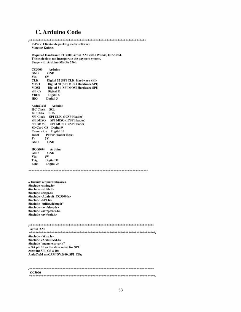
53
C. Arduino Code
/**************************************************************************
E-Park. Client-side parking meter software.
Mateusz Kulesza
Required Hardware: CC3000, ArduCAM with OV2640, HC-SR04.
This code does not incorporate the payment system.
Usage with Arduino MEGA 2560:
CC3000 Arduino
GND GND
Vin 5V
CLK Digital 52 (SPI CLK Hardware SPI)
MISO Digital 50 (SPI MISO Hardware SPI)
MOSI Digital 51 (SPI MOSI Hardware SPI)
SPI CS Digital 11
VBEN Digital 5
IRQ Digital 3
ArduCAM Arduino
I1C Clock SCL
I2C Data SDA
SPI Clock SPI CLK (ICSP Header)
SPI MISO SPI MISO (ICSP Header)
SPI MOSI SPI MOSI (ICSP Header)
SD Card CS Digital 9
Camera CS Digital 10
Reset Power Header Reset
5V 5V
GND GND
HC-SR04 Arduino
GND GND
Vin 5V
Trig Digital 37
Echo Digital 36
***************************************************************************/
// Include required libraries.
#include <string.h>
#include <stdlib.h>
#include <ccspi.h>
#include <Adafruit_CC3000.h>
#include <SPI.h>
#include "utility/debug.h"
#include <avr/sleep.h>
#include <avr/power.h>
#include <avr/wdt.h>
/*******************************************************************************
ArduCAM
********************************************************************************/
#include <Wire.h>
#include <ArduCAM.h>
#include "memorysaver.h"
// Set pin 10 as the slave select for SPI.
const int SPI_CS = 10;
ArduCAM myCAM(OV2640, SPI_CS);
/*******************************************************************************
CC3000
********************************************************************************/
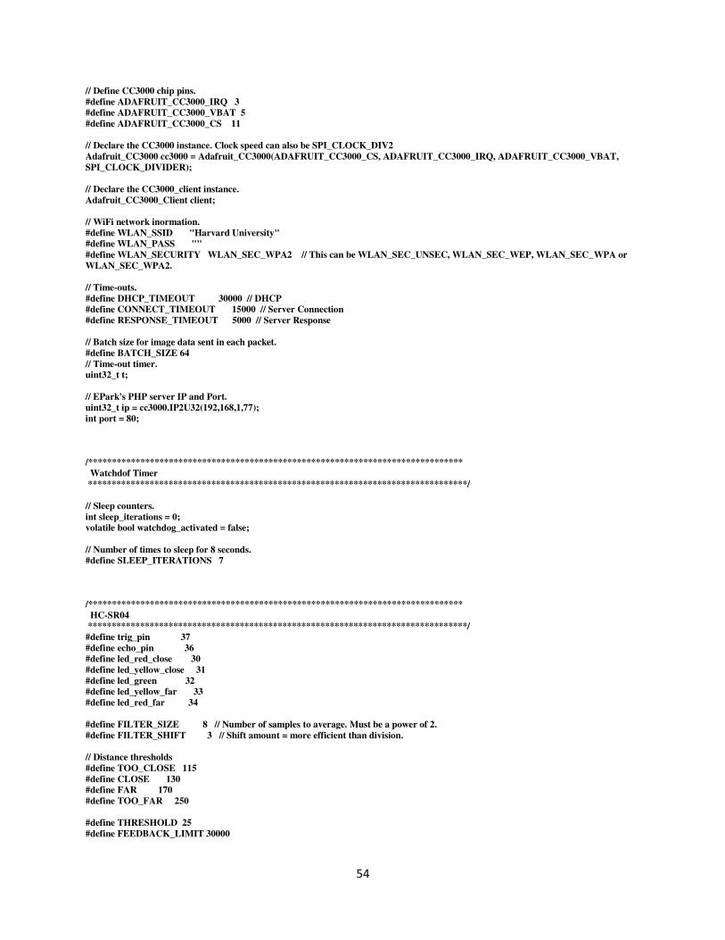
54
// Define CC3000 chip pins.
#define ADAFRUIT_CC3000_IRQ 3
#define ADAFRUIT_CC3000_VBAT 5
#define ADAFRUIT_CC3000_CS 11
// Declare the CC3000 instance. Clock speed can also be SPI_CLOCK_DIV2
Adafruit_CC3000 cc3000 = Adafruit_CC3000(ADAFRUIT_CC3000_CS, ADAFRUIT_CC3000_IRQ, ADAFRUIT_CC3000_VBAT,
SPI_CLOCK_DIVIDER);
// Declare the CC3000_client instance.
Adafruit_CC3000_Client client;
// WiFi network inormation.
#define WLAN_SSID "Harvard University"
#define WLAN_PASS ""
#define WLAN_SECURITY WLAN_SEC_WPA2 // This can be WLAN_SEC_UNSEC, WLAN_SEC_WEP, WLAN_SEC_WPA or
WLAN_SEC_WPA2.
// Time-outs.
#define DHCP_TIMEOUT 30000 // DHCP
#define CONNECT_TIMEOUT 15000 // Server Connection
#define RESPONSE_TIMEOUT 5000 // Server Response
// Batch size for image data sent in each packet.
#define BATCH_SIZE 64
// Time-out timer.
uint32_t t;
// EPark's PHP server IP and Port.
uint32_t ip = cc3000.IP2U32(192,168,1,77);
int port = 80;
/*******************************************************************************
Watchdof Timer
********************************************************************************/
// Sleep counters.
int sleep_iterations = 0;
volatile bool watchdog_activated = false;
// Number of times to sleep for 8 seconds.
#define SLEEP_ITERATIONS 7
/*******************************************************************************
HC-SR04
********************************************************************************/
#define trig_pin 37
#define echo_pin 36
#define led_red_close 30
#define led_yellow_close 31
#define led_green 32
#define led_yellow_far 33
#define led_red_far 34
#define FILTER_SIZE 8 // Number of samples to average. Must be a power of 2.
#define FILTER_SHIFT 3 // Shift amount = more efficient than division.
// Distance thresholds
#define TOO_CLOSE 115
#define CLOSE 130
#define FAR 170
#define TOO_FAR 250
#define THRESHOLD 25
#define FEEDBACK_LIMIT 30000

55
long last_distance;
int feedback_time = 0;
#define PAID_TIME_TEST 180000
long paid_timer = 0;
void setup(void) {
// Start the serial connection.
Serial.begin(115200);
Serial.println(F("Hello, CC3000!\n"));
// Display the state of the RAM.
Serial.print(F("Free RAM: "));
Serial.println(getFreeRam(), DEC);
// Setup the watchdog timer to run an interrupt which
// wakes the Arduino from sleep every 8 seconds.
noInterrupts();
// Set the watchdog reset bit in the MCU status register to 0.
MCUSR &= ~(1 << WDRF);
// Set WDCE and WDE bits in the watchdog control register.
WDTCSR |= (1 << WDCE) | (1 << WDE);
// Set watchdog clock prescaler bits to a value of 8 seconds.
WDTCSR = (1 << WDP0) | (1 << WDP3);
// Enable watchdog as interrupt only (no reset).
WDTCSR |= (1 << WDIE);
// Enable interrupts again.
interrupts();
Serial.println(F("Sleep Setup complete."));
// ArduCAM variables
uint8_t vid, pid;
uint8_t temp;
#if defined (__AVR__)
Wire.begin();
#endif
#if defined(__arm__)
Wire1.begin();
#endif
Serial.println("ArduCAM Start!");
// set the SPI_CS as an output:
pinMode(SPI_CS, OUTPUT);
// Initialize SPI.
SPI.begin();
// Check if the ArduCAM SPI bus is ok.
myCAM.write_reg(ARDUCHIP_TEST1, 0x55);
temp = myCAM.read_reg(ARDUCHIP_TEST1);
if(temp != 0x55) {
Serial.println("SPI interface Error!");
return;
}
else
Serial.println("SPI Good!");
// Change MCU mode.
myCAM.write_reg(ARDUCHIP_MODE, 0x00);
//Check if the camera module type is OV2640
myCAM.rdSensorReg8_8(OV2640_CHIPID_HIGH, &vid);
myCAM.rdSensorReg8_8(OV2640_CHIPID_LOW, &pid);

56
if((vid != 0x26) || (pid != 0x42))
Serial.println("Can't find OV2640 module!");
else
Serial.println("OV2640 detected");
myCAM.set_format(JPEG);
myCAM.InitCAM();
myCAM.OV2640_set_JPEG_size(OV2640_1024x768);
// Initialize the HC-SR04 pin functions.
pinMode(trig_pin, OUTPUT);
pinMode(echo_pin, INPUT);
pinMode(led_red_close, OUTPUT);
pinMode(led_yellow_close, OUTPUT);
pinMode(led_green, OUTPUT);
pinMode(led_red_far, OUTPUT);
pinMode(led_yellow_far, OUTPUT);
// Start the trigger in the LOW position.
digitalWrite(trig_pin, LOW);
}
void loop(void) {
// Don't do anything unless the watchdog timer interrupt has fired.
if (watchdog_activated) {
watchdog_activated = false;
// Increase the count of sleep iterations
sleep_iterations += 1;
Serial.println(F("Sleeping"));
if (sleep_iterations >= SLEEP_ITERATIONS) {
// Reset the number of sleep iterations.
sleep_iterations = 0;
// Vehicle detected?
long difference = get_distance() - last_distance;
if ((difference > THRESHOLD) || (difference < -THRESHOLD)) {
// Start offering feedback
feedback_time = millis();
while ((millis() - feedback_time) < FEEDBACK_LIMIT) {
feedback();
}
// Wait for payment - requires payment system implementation
paid_timer = millis();
}
}
if ((millis() - paid_timer) > PAID_TIME_TEST) {
issue_fine();
}
}
// Go to sleep.
sleep();
}
/*******************************************************************************
issue_fine()
Conects to the defined network and the EPark back-end server at the
specified IP address. Takes the image of the vehicle, sends it to the server,
and disconnects from the access point.
********************************************************************************/

57
void issue_fine (void) {
// Initialize the module.
Serial.println(F("\nInitializing"));
if (!cc3000.begin()) {
Serial.println(F("Initialization failed. Check your wiring."));
return;
}
// Connect to the access point.
Serial.print(F("Attempting to connect to "));
Serial.println(WLAN_SSID);
if (!cc3000.connectToAP(WLAN_SSID, WLAN_PASS, WLAN_SECURITY)) {
Serial.println(F("Failed!"));
return;
}
else
Serial.println(F("Connected!"));
// Request address from dynamic host configuration protocol.
Serial.println(F("Requesting address from DHCP server."));
for (t = millis(); !cc3000.checkDHCP() && ((millis() - t) < DHCP_TIMEOUT); delay(500)) {
Serial.println(F("Waiting for DHCP address"));
}
if (cc3000.checkDHCP()) {
Serial.println(F("DHCP Acquired"));
}
else {
Serial.println(F("DHCP Acquisition Failed"));
return;
}
// Display the IP address DNS, Gateway, etc.
/*while (!display_connection_details()) {
delay(1000);
}*/
// Try looking up the website's IP address.
// Not needed here because we connect directly via IP address.
/*ip = 0;
while (ip == 0 || ip == 2130706433) {
if (!cc3000.getHostByName(WEBSITE, &ip)) {
Serial.println(F("Couldn't resolve!"));
}
Serial.println(ip);
delay(500);
}*/
Serial.println();
Serial.print(F("Server IP Address: "));
cc3000.printIPdotsRev(ip);
//Open Socket.
Serial.println(F("\n\nConnecting to server"));
t = millis();
do {
client = cc3000.connectTCP(ip, port);
}
while((!client.connected()) && ((millis() - t) < CONNECT_TIMEOUT));
// Send request.
if (client.connected()) {
Serial.println(F("Connected"));
send_image(1);
}
else {
Serial.println(F("Connection failed"));
return;
}
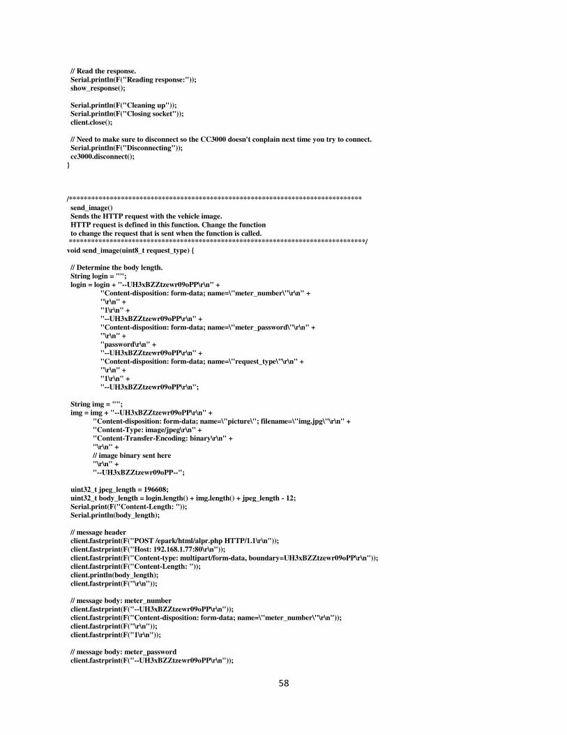
58
// Read the response.
Serial.println(F("Reading response:"));
show_response();
Serial.println(F("Cleaning up"));
Serial.println(F("Closing socket"));
client.close();
// Need to make sure to disconnect so the CC3000 doesn't conplain next time you try to connect.
Serial.println(F("Disconnecting"));
cc3000.disconnect();
}
/*******************************************************************************
send_image()
Sends the HTTP request with the vehicle image.
HTTP request is defined in this function. Change the function
to change the request that is sent when the function is called.
********************************************************************************/
void send_image(uint8_t request_type) {
// Determine the body length.
String login = "";
login = login + "--UH3xBZZtzewr09oPP\r\n" +
"Content-disposition: form-data; name=\"meter_number\"\r\n" +
"\r\n" +
"1\r\n" +
"--UH3xBZZtzewr09oPP\r\n" +
"Content-disposition: form-data; name=\"meter_password\"\r\n" +
"\r\n" +
"password\r\n" +
"--UH3xBZZtzewr09oPP\r\n" +
"Content-disposition: form-data; name=\"request_type\"\r\n" +
"\r\n" +
"1\r\n" +
"--UH3xBZZtzewr09oPP\r\n";
String img = "";
img = img + "--UH3xBZZtzewr09oPP\r\n" +
"Content-disposition: form-data; name=\"picture\"; filename=\"img.jpg\"\r\n" +
"Content-Type: image/jpeg\r\n" +
"Content-Transfer-Encoding: binary\r\n" +
"\r\n" +
// image binary sent here
"\r\n" +
"--UH3xBZZtzewr09oPP--";
uint32_t jpeg_length = 196608;
uint32_t body_length = login.length() + img.length() + jpeg_length - 12;
Serial.print(F("Content-Length: "));
Serial.println(body_length);
// message header
client.fastrprint(F("POST /epark/html/alpr.php HTTP/1.1\r\n"));
client.fastrprint(F("Host: 192.168.1.77:80\r\n"));
client.fastrprint(F("Content-type: multipart/form-data, boundary=UH3xBZZtzewr09oPP\r\n"));
client.fastrprint(F("Content-Length: "));
client.println(body_length);
client.fastrprint(F("\r\n"));
// message body: meter_number
client.fastrprint(F("--UH3xBZZtzewr09oPP\r\n"));
client.fastrprint(F("Content-disposition: form-data; name=\"meter_number\"\r\n"));
client.fastrprint(F("\r\n"));
client.fastrprint(F("1\r\n"));
// message body: meter_password
client.fastrprint(F("--UH3xBZZtzewr09oPP\r\n"));

59
client.fastrprint(F("Content-disposition: form-data; name=\"meter_password\"\r\n"));
client.fastrprint(F("\r\n"));
client.fastrprint(F("password\r\n"));
// message body: request_type
client.fastrprint(F("--UH3xBZZtzewr09oPP\r\n"));
client.fastrprint(F("Content-disposition: form-data; name=\"request_type\"\r\n"));
client.fastrprint(F("\r\n"));
client.println(request_type);
client.fastrprint(F("\r\n"));
client.fastrprint(F("--UH3xBZZtzewr09oPP\r\n"));
// message body: image
client.fastrprint(F("--UH3xBZZtzewr09oPP\r\n"));
client.fastrprint(F("Content-disposition: form-data; name=\"picture\"; filename=\"img.jpg\"\r\n"));
client.fastrprint(F("Content-Type: image/jpeg\r\n"));
client.fastrprint(F("Content-Transfer-Encoding: binary\r\n"));
client.fastrprint(F("\r\n"));
//uint32_t buf[] = {0, 1};
//client.write(buf, jpeg_length);
// Variables to contain the image data.
byte buf[BATCH_SIZE] = {0};
uint8_t last = 0;
uint32_t image_size = 0;
uint32_t i = 0;
uint32_t send_timer = millis();
//Flush the FIFO, clear the flag.
myCAM.flush_fifo();
myCAM.clear_fifo_flag();
//Start capture
myCAM.start_capture();
Serial.println("Start Capture");
delay(1000);
if (myCAM.read_reg(ARDUCHIP_TRIG) & CAP_DONE_MASK) {
Serial.println("Capture Done!");
//Read JPEG data from FIFO
while((buf[i] != 0xD9) | (last != 0xFF)) {
last = buf[i];
buf[i] = myCAM.read_fifo();
image_size++;
i++;
if (i == BATCH_SIZE) {
client.write(buf, BATCH_SIZE);
i = 0;
// Report the progress
Serial.print("Bytes sent: ");
Serial.println(image_size);
}
}
myCAM.clear_fifo_flag();
Serial.print("\nImage Size: ");
Serial.println(image_size);
jpeg_length = jpeg_length - image_size;
while(jpeg_length > 0) {
if (jpeg_length > BATCH_SIZE) {
client.write(buf, BATCH_SIZE);
jpeg_length = jpeg_length - BATCH_SIZE;
}
else {
60
client.write(buf, jpeg_length);
jpeg_length = 0;
}
// Report the progress
Serial.print("Bytes left: ");
Serial.println(jpeg_length);
}
}
// Report how long it took to send the image
send_timer = millis() - send_timer;
Serial.print("\nSending time: ");
Serial.println(send_timer);
client.fastrprint(F("\r\n"));
client.fastrprint(F("--UH3xBZZtzewr09oPP--"));
}
/*******************************************************************************
show_response()
Read data until either the connection is closed, or the idle timeout is reached.
********************************************************************************/
void show_response() {
unsigned long lastRead = millis();
while (client.connected() && (millis() - lastRead < RESPONSE_TIMEOUT)) {
while (client.available()) {
char c = client.read();
Serial.print(c);
lastRead = millis();
}
}
}
/*******************************************************************************
display_connection_details(void)
Tries to read the IP address and other connection details.
********************************************************************************/
bool display_connection_details(void) {
uint32_t ip_address, netmask, gateway, dhcpserv, dnsserv;
if(!cc3000.getIPAddress(&ip_address, &netmask, &gateway, &dhcpserv, &dnsserv)) {
Serial.println(F("Unable to retrieve the IP Address!\r\n"));
return false;
}
else {
Serial.print(F("\nIP Addr: ")); cc3000.printIPdotsRev(ip_address);
Serial.print(F("\nNetmask: ")); cc3000.printIPdotsRev(netmask);
Serial.print(F("\nGateway: ")); cc3000.printIPdotsRev(gateway);
Serial.print(F("\nDHCPsrv: ")); cc3000.printIPdotsRev(dhcpserv);
Serial.print(F("\nDNSserv: ")); cc3000.printIPdotsRev(dnsserv);
Serial.println();
return true;
}
}
/*******************************************************************************
ISR()
Defines the watchdog timer interrupt.
********************************************************************************/
ISR(WDT_vect) {
// Set the watchdog activated flag.
watchdog_activated = true;
}

61
/*******************************************************************************
sleep()
Puts the Arduino into a low-power sleep mode.
********************************************************************************/
void sleep() {
// Set sleep to full power down. Only external interrupts or
// the watchdog timer can wake the CPU!
set_sleep_mode(SLEEP_MODE_PWR_DOWN);
// Turn off the ADC while asleep.
power_adc_disable();
// Enable sleep and enter sleep mode.
sleep_mode();
// When awake, disable sleep mode and turn on all devices.
sleep_disable();
power_all_enable();
}
/*******************************************************************************
feedback()
Provides visual feedback to the driver.
********************************************************************************/
void feedback () {
long distance = 0;
distance = get_distance();
// Vehicle too close to the meter.
if (distance < TOO_CLOSE) {
digitalWrite(led_red_close, LOW);
digitalWrite(led_yellow_close, HIGH);
digitalWrite(led_green, HIGH);
digitalWrite(led_yellow_far, HIGH);
digitalWrite(led_red_far, HIGH);
delay(500);
}
// Vehicle almost right - close side.
else if ((distance < CLOSE) && (distance > TOO_CLOSE)) {
digitalWrite(led_red_close, HIGH);
digitalWrite(led_yellow_close, LOW);
digitalWrite(led_green, HIGH);
digitalWrite(led_yellow_far, HIGH);
digitalWrite(led_red_far, HIGH);
delay(500);
}
// Vehicle positioned correctly.
else if (distance < FAR && distance > CLOSE) {
digitalWrite(led_red_close, HIGH);
digitalWrite(led_yellow_close, HIGH);
digitalWrite(led_green, LOW);
digitalWrite(led_yellow_far, HIGH);
digitalWrite(led_red_far, HIGH);
delay(500);
}
// Vehicle almost right - far side.
else if ((distance < TOO_FAR) && (distance > FAR)) {
digitalWrite(led_red_close, HIGH);
digitalWrite(led_yellow_close, HIGH);
digitalWrite(led_green, HIGH);
digitalWrite(led_yellow_far, LOW);
digitalWrite(led_red_far, HIGH);
delay(500);

62
}
else if (distance > TOO_FAR) {
digitalWrite(led_red_close, HIGH);
digitalWrite(led_yellow_close, HIGH);
digitalWrite(led_green, HIGH);
digitalWrite(led_yellow_far, HIGH);
digitalWrite(led_red_far, LOW);
}
}
/*******************************************************************************
get_distance()
Reports the measurement from the HC-SR04.
********************************************************************************/
long get_distance () {
long duration = 0;
long distance = 0;
int i = 0;
for (i = 0; i < FILTER_SIZE; i++) {
// Send a 10us minimum HIGH signal to start the rangefinder.
digitalWrite(trig_pin, LOW);
delayMicroseconds(2);
digitalWrite(trig_pin, HIGH);
delayMicroseconds(10);
digitalWrite(trig_pin, LOW);
// Wait for the echo_pin to go high, then start timing the signal.
duration = duration + pulseIn(echo_pin, HIGH);
}
// Compute the distance in cm.
distance = (duration >> FILTER_SHIFT)/58;
return distance;
}

63
D. Power Plots
Arduino MEGA 2560. The low 375 mW region corresponds to the sleep mode while the higher region corresponds to active mode.
CC3000. The low region corresponds to the module being in sleep mode. The high region represents active TX/RX mode.

64
ArduCAM with OV2640.
HC-SR04 Distance Feedback Sensor and LED’s

65
4 Line 20 Character LCD Screen with Backlight On.