e c u talk® d i a g n o s t i c u s e r m a n u a l g u i d e f o r ... e c u t a l k ® d i a g n...
TRANSCRIPT

C o m m e r c i a l V e h i c l e S y s t e m s
U s e r M a n u a l
E C U t a l k ® D i a g n o s t i c G u i d e f o r T I M G 2

Disclaimer:The information contained herein is intended for the exclusive use of trained persons within the commercial vehicle industry, and must not be passed on to any third party.
All recommendations regarding products and their servicing or usage are with reference to Knorr-Bremse products and should not be considered applicable to products from other manufacturers.
This information does not purport to be all-inclusive and no responsibility is assumed as a result of its use. We cannot accept any liability nor offer any guarantee regarding data accuracy, completeness or timeliness. The information does not represent any guarantee or ensured characteristics of the Products or Systems described.
No liability can be accepted based on the information, its use, recommendations or advice provided. In no event may we be held liable for any damage or loss except in the case of wilful intent or gross negligence on our part, or if any mandatory legal provisions apply.
This disclaimer is an English translation of a German text, which should be referred to for all legal purposes.
Any legal disputes arising from the use of this information shall be subject to German law.
Disposal of Waste Equipment by Business Users in the European UnionThis symbol on the product, packaging or in user instructions, indicates that this product must not be disposed of with other general waste. Instead, it is your responsibility to dispose of the waste electrical and electronic parts of this product by handing them over to a company or organisation authorised for the recycling of waste electrical and electrical equipment. For more information about arrangements for waste equipment disposal please contact your Knorr-Bremse distributor or local Knorr-Bremse representative.

�
E C U t a l k ® D i a g n o s t i c G u i d e f o r T I M G 2
ECU talk® Diagnostic Guide for TIM G2
C o m m e r c i a l V e h i c l e S y s t e m s

�
U s e r M a n u a l
Note: The safety advice below is applicable to general service and diagnostic work on air braking systems and may not all be directly relevant to the activities and products described in this document.
Before and whilst working on or around air braking systems and devices, the following precautions should be observed in addition to any specific advice given in this document:
• Always wear safety glasses when working with air pressure.
• Never exceed manufacturer’s recommended air pressures.
• Never look into air jets or direct them at anyone.
• Never connect or disconnect a hose or line containing pressure; it may whip as air escapes.
• Never remove a device or pipe plug unless you are certain all system pressure has been depleted.
• Park the vehicle on a level surface, apply the parking brakes, and always chock the wheels as depleting vehicle air system pressure may cause the vehicle to roll.
• If work is being performed on the vehicle’s air braking system, or any auxiliary pressurised air systems, and if it is necessary to drain the air pressure from reservoirs, etc., keep clear of brake actuator push rods and levers since they may move as system pressure drops. Be aware that if the vehicle is equipped with an air dryer system, it can also contain air pressure along with its purge reservoir, if fitted, even after pressure has been drained from the other reservoirs.
• When working under or around the vehicle, and particularly when working in the engine compartment, the engine should be shut off and the ignition key removed. Where circumstances require that the engine be running, EXTREME CAUTION should be taken to prevent personal injury resulting from contact with moving, rotating, leaking, heated or electrically charged components. Additionally, it is advisable to place a clear sign on or near the steering wheel advising that there is work in progress on the vehicle.
• Examine all pipework for signs of kinks, dents, abrasion, drying out or overheating. Be aware that kinks in pipework may result in air pressure being trapped in the pipework and associated equipment. Replacement hardware, tubing, hose, fittings, etc. must be of equivalent size, type and strength as original equipment and be designed specifically for such applications and systems. Check the attachment of all pipework; it should be supported so that it cannot abrade or be subjected to excessive heat.
• Components with stripped threads or damaged/corroded parts should be replaced rather than repaired. Do not attempt repairs requiring machining or welding unless specifically stated and approved by the vehicle or component manufacturer.
• Never attempt to install, remove, disassemble or assemble a device until you have read and thoroughly understood the recommended procedures. Some units contain powerful springs and injury can result if not properly dismantled. Use only the correct tools and observe all precautions pertaining to use of those tools. Before removing any device note its position and the connections of all pipework so that the replacement/serviced device can be properly installed. Ensure that adequate support or assistance is provided for the removal/installation of heavy items.
• Use only genuine Knorr-Bremse replacement parts, components and kits.
• Prior to returning the vehicle to service, make certain all components and systems are leak free and restored to their proper operating condition.
Welding
To avoid damage to electronic components when carrying out electrical welding, the following precautions should be observed:
• In all cases, before starting any electrical welding, remove all connections from any electronic control units or modules, noting their position and the order in which they are removed.
• When re-inserting the electrical connectors (in reverse order) it is essential that they are fitted to their correct assigned position - if necessary this must be checked by PC Diagnostics.
S a f e t y A d v i c e

�
E C U t a l k ® D i a g n o s t i c G u i d e f o r T I M G 2
ContentsPage
1. Introduction . . . . . . . . . . . . . . . . . . . . . . . . . . . . 6
1.1 Generaldescription. . . . . . . . . . . . . . . . . . . . . . . 6 1.2 Features. . . . . . . . . . . . . . . . . . . . . . . . . . .6
2. Installation Instructions for ECUtalk® . . . . . . . . . . . . . . . . . . . . 7
2.1 SystemRequirements. . . . . . . . . . . . . . . . . . . . . . 7 2.2 InitialInstallation . . . . . . . . . . . . . . . . . . . . . . . . 7 2.2.1 Download and Installation Guide . . . . . . . . . . . . . . . . . 7
2.3 ProgramStart. . . . . . . . . . . . . . . . . . . . . . . . .8
3. Starting Diagnostic Session . . . . . . . . . . . . . . . . . . . . . . . 9
3.1 StartingtheProgram. . . . . . . . . . . . . . . . . . . . . . .9 3.1.1 UDIF Software. . . . . . . . . . . . . . . . . . . . . . . 11
3.1.2 License Load and Register . . . . . . . . . . . . . . . . . . . 14
3.2 OperatingModesandAccessLevels. . . . . . . . . . . . . . . . . .15 3.3 CommunicationInterfaces-IndicationofDiagnosticMode. . . . . . . . . . .15
4. Configuration Information . . . . . . . . . . . . . . . . . . . . . . . . 18
4.1 InitialisationandConfigurationInformationScreen. . . . . . . . . . . . . 18 4.2 StoringtheConfigurationintheECU. . . . . . . . . . . . . . . . . .20
5. Error handling . . . . . . . . . . . . . . . . . . . . . . . . . . . . 21
6. Dynamic Menu Setting . . . . . . . . . . . . . . . . . . . . . . . . . 22
6.1 VirtualSwitches . . . . . . . . . . . . . . . . . . . . . . . .23 6.2 EditingofMenuentries . . . . . . . . . . . . . . . . . . . . . .24
7. TIM G2 Menu Language Packs . . . . . . . . . . . . . . . . . . . . . . 25
8. Time Zone Settings . . . . . . . . . . . . . . . . . . . . . . . . . . 26
9. Conversion to Handheld . . . . . . . . . . . . . . . . . . . . . . . . 27
10. TIM G2’s Advanced Data Recorder Handling . . . . . . . . . . . . . . . . . . 28
10.1 EnablingTDR . . . . . . . . . . . . . . . . . . . . . . . . .28 10.2 EnablingTDRRetrospectively . . . . . . . . . . . . . . . . . . . .29 10.3 UploadingTDR. . . . . . . . . . . . . . . . . . . . . . . . .29 10.4 Savedataset . . . . . . . . . . . . . . . . . . . . . . . . .31 10.5 TheTDRPasswordDialogue . . . . . . . . . . . . . . . . . . . .31
11. Unlock TIM . . . . . . . . . . . . . . . . . . . . . . . . . . . . 32
11.1 Unlockingindemomode. . . . . . . . . . . . . . . . . . . . . 32 11.2 Unlockinginrealmode . . . . . . . . . . . . . . . . . . . . . .34
12. Flash . . . . . . . . . . . . . . . . . . . . . . . . . . . . 35
13. CodeMeter . . . . . . . . . . . . . . . . . . . . . . . . . . . . 41
14. Tools . . . . . . . . . . . . . . . . . . . . . . . . . . . . 42

�
1
U s e r M a n u a l
I n t r o d u c t i o n
1.1 General description
This Document is a user guide for the TIM G2 PC diagnostics and describes the usage of the program ECUtalk®.
The ECUtalk® TIM G2 PC diagnostics is a program that is able to configure the Trailer Information Module (TIM) installed with the TEBS G2 braking system and hence control the functional behaviour of that system. The program can interrogate the system’s fault storage, flash TIM G2 update, download language packages and upload Trailer Data Recordern (TDR) information.
During configuration of the TIM G2 unit the personal identification number (PIN) code associated with the authorised user is stored within the ECU and may be accessed for future reference.
1.2 Features
ECUtalk® for TIM G2 enables the user to:
Read production information
Read error information
Configure TIM G2 menu items
Download TIM G2 language packs
Adjust time zone setting
Flash update packages
Convert to workshop tool 1)
Enable TDR 1)
Upload TDR 2)
Unlock TIM 1)
1) This functionality needs a Dongle, ask your local Knorr-Bremse Sales representative for more information.2) Only if enabled in TIM.
•
•
•
•
•
•
•
•
•
•

�
2
E C U t a l k ® D i a g n o s t i c G u i d e f o r T I M G 2
I n s t a l l a t i o n I n s t r u c t i o n s f o r E C U ta l k®
2.1 System Requirements
Windows® XP SP3, Windows Vista®, Windows® 7100 Mbytes free Hard Drive space available. Display resolution should be 1024x768 or higher, with 256 colours or more.
Note: It is strongly recommended to use standard font type (96dpi). The use of “small fonts”, “big fonts” and “very big fonts” is not allowed (selectable under Desktop Properties)!
CAUTION - When your PC is running Windows XP®, Windows Vista® or Windows 7® you need administrator rights to install the program!
CAUTION - To avoid possible loss of data, all applications should be closed before installation is started!
2.2.1 Download and Installation Guide:
1. Visit website www.knorr-bremseCVS.com
2. Click on “Service and Support”
3. Select “Software Download”
4. Filter on “Software Type “Installation Pack”
5. Select “ECUtalk® TIM G2 installation pack“
6. Read the specification page then click on the Register button
7. Enter all required details on the Application Form, read the License Agreement and click Send
8. You will then receive an email from Knorr-Bremse with a link to the latest software
9. Click on the link
10. Extract the .zip file to a folder on your hard disk
11. Double click the TIMG2Packv.1.x.y.z.exe file
12. Follow the installation instructions
2.2 Initial Installation
For installation of ECUtalk® for TIM G2 it is first necessary to register with Knorr-Bremse to request a link to the software and a Personal Identification Number (PIN) code.

�
2
U s e r M a n u a l
I n s t a l l a t i o n I n s t r u c t i o n s f o r E C U ta l k®
2.3 Program Start
Before ECUtalk® is started, the communication interface UDIF must be connected to the Electronic Control Unit (ECU) and to the “COM1”- or “COM2” - serial interface connector at the PC (9-pin connector). The TIM G2 unit must be powered before communications will commence.
If no serial port is available, the Knorr-Bremse recommended USB to serial adapter cable Z007887 can be used as an alternative (Note a proprietary cable may not work correctly). When this is used the appropriate USB to serial driver must first be installed on the PC. The serial driver is included on the CD supplied with the cable adaptor or may be obtained from your Knorr-Bremse representative.
The software version of UDIF should be updated if necessary. For this operation refer to section 3.1.1 “UDIF_Software”.

�
3
E C U t a l k ® D i a g n o s t i c G u i d e f o r T I M G 2
S t a r t i n g D i a g n o s t i c S e s s i o n
3.1 StartingoftheProgram
The Knorr-Bremse Starter Application for ECUtalk® programs can be started with the desktop icon (Fig. 1).
The program will start with a double-click on this icon.
ECUtalk® can also be started by using the “Start” menu. Click on the entry “ECUtalk® G2 Trailer” in the programs menu (START ->Programs -> Knorr-> ECUtalk® G2 Trailer ).
This will open the KB-Starter Application (Fig. 2)
On the left side a list of the currently installed Knorr-Bremse PC diagnostic programs is displayed and the required system option should be selected.On the right side the button control field is displayed for selection of Diagnostic Controls and Tools.
Fig. 1
Fig. 2
Selecting the button opens a user dialogue where the operator could manually assign the PC’s COM port for serial communication to ECUtalk® under the tab “UDIF”.

10
3
U s e r M a n u a l
S t a r t i n g D i a g n o s t i c S e s s i o n
DiagnosticControlButtons
To be selected when an actual ECU is connected.
To be selected when no ECU is connected but it is required to see how the program works.
Will check whether an ECU is connected, each system listed is checked in turn until the correct system is found.
Will open a dialogue where the user may activate the logging function.
Note: Activate “Data logger” will open the data logging tool (Fig. 4) which may be helpful to diagnose communication problems at start up.
Fig.3
Start with ECU
Start in demo mode
Detect ECU
Options

11
3
E C U t a l k ® D i a g n o s t i c G u i d e f o r T I M G 2
S t a r t i n g D i a g n o s t i c S e s s i o n
Enables the user to update the diagnostic interface UDIF (see section 3.1.1).
Opens a window to allow the user to load and register the ‘User PIN’ code (see section 3.1.2).
Fig. 4
3.1.1 UDIFSoftware
When starting a session of ECUtalk®, the software version of the UDIF interface is automatically checked. If the UDIF is programmed with a lower software level than that required to run the diagnostic program with the connected TEBS G2, ECUtalk® will automatically detect the incompatibility and proceed in “Demo Mode”. The following message will then appear:
Fig. 5
UDIF download
License manager

12
3
U s e r M a n u a l
S t a r t i n g D i a g n o s t i c S e s s i o n
Until the UDIF is re-programmed with a compatible level of software, ECUtalk® will not establish communications with the TEBS G2.
ECUtalk® first detects whether the UDIF is connected to the PC. To detect the presence of the UDIF it is not necessary for the UDIF to be powered. However to enable ECUtalk® to determine the software level of the UDIF, it must be powered. (It is not necessary to connect the UDIF to a TEBS only to ensure that it is powered). The ECUtalk® software package includes the most recent UDIF software which is automatically detected.
Click on OK to close error message.
Close the ECUtalk® application
Select button “UDIF download” (Fig. 6) to open the “Software upgrade screen” (Fig. 7)
Fig. 6
Fig. 7

1�
3
E C U t a l k ® D i a g n o s t i c G u i d e f o r T I M G 2
S t a r t i n g D i a g n o s t i c S e s s i o n
Button Description‘UDIF version’ Software level currently programmed into the UDIF.
‘Detect UDIF’ ECUtalk® detects when a UDIF is connected and defines the associated port number. Note: If a ‘USB to serial’ cable is used the COM port number may be higher than the number of ports existing on the PC.
‘File’ Defines the software file stored within ECUtalk® to re-program the UDIF.
‘Download’ Carries out the UDIF software upgrade.
‘Save log’ Stores the log information from a central list to a file.
‘Clear log’ Clears the list.
Terminology
If the UDIF is programmed with a higher software level than that stored within ECUtalk® the following warning is displayed:
During software download, ECUtalk® displays the download status:
When a software upgrade has been successfully completed, a message displays this status. To check the actual software level installed within the UDIF, select the “UDIF version” button.
Fig. 8
Fig. 9

1�
3
U s e r M a n u a l
S t a r t i n g D i a g n o s t i c S e s s i o n
Load the licence file by selecting the “Load” button (Fig. 10) which will open a new window (Fig. 11).
If you already own a licence on the target PC no additional PIN code is needed. For stand-alone usage a TIM G2 “General Licence” PIN code is required.
For the latter case, select your licence file (file.lic) and then click on the “Open” button (Fig. 11).
Fig. 10
Fig. 11
3.1.2 License Load and Register

1�
3
E C U t a l k ® D i a g n o s t i c G u i d e f o r T I M G 2
S t a r t i n g D i a g n o s t i c S e s s i o n
Activate your licence by selecting the “Register” button (Fig.12).
Fig. 12
3.2 Operating Modes and Access Levels
ECUtalk® operates in different modes depending on the diagnostic user interface and licence key authorisation.
PIN Code
ECUtalk® utilises a user-locked licensing mechanism. Each user registered by Knorr-Bremse will receive a license file which must be entered into the system (detailed instructions are sent along with a PIN code) in order to make the ECUtalk® application fully functional.If the program cannot find the licence key it will not run!
For details about how to activate the PIN code please see document Y037127 (ECUtalk® Diagnostic Guide for TEBS G2).
3.3 Communication Interfaces - Indication of Diagnostic Mode
ECUtalk® is able to communicate with TIM G2 via either of two diagnostic interfaces:• UDIF interface with 24V CAN (ISO 7638), 7-pin headboard connection• UDIF interface with 5V CAN (side of vehicle option)
Under normal conditions the TIM G2 ECUtalk® diagnostics will detect the connected communication line automatically as well as the associated COM Port.

1�
3
U s e r M a n u a l
S t a r t i n g D i a g n o s t i c S e s s i o n
If the communication to the ECU cannot be established the following dialogue is shown (Fig. 13):
Fig. 13
Clicking on “Cancel” will close the window, while “Try again” starts another communication initialisation.For assistance open the “Troubleshooting guide” (Fig. 14).
Fig. 14
First select the question mark button (1), this will open the “Starter help” screen. Select “Detection Errors” (2) in the chapter “Starting of the Program”. This will show possible reasons for general communication problems.
1
2

1�
3
E C U t a l k ® D i a g n o s t i c G u i d e f o r T I M G 2
S t a r t i n g D i a g n o s t i c S e s s i o n
Fig. 19
Indication of Diagnostic Mode
If ECUtalk® is able to communicate with an ECU, this is indicated in the “Status bar” by an alternating symbol (Fig. 15 and Fig. 16).
Fig. 15 Fig. 16
A broken communication is indicated by the following symbol (Fig. 17).
Fig. 17
If ECUtalk® is running in Demo Mode this is indicated by the following symbol (Fig. 18).
Fig. 18
When ECUtalk® detects that communication to the ECU has been broken due to the ignition being switched off, a message is displayed (Fig. 19).
Selecting “Reconnect” means that ECUtalk® will try to restart communications. Selecting “Demo mode” switches to ’Demo Mode’.
If communications are resumed, ECUtalk® will re-start the diagnostic session. If the conditions are still not correct however, e.g. the ignition is not on, ECUtalk® displays the same message again.

1�
4
U s e r M a n u a l
C o n f i g u r a t i o n I n f o r m a t i o n
4.1 Initialisation and Configuration Information Screen
The information shown on this page may vary dependent on the versions of ECUtalk® and the TIM G2 application program. Only that information is shown which is supported by the currently diagnosed system.
The “Configuration Information” screen (Fig. 20) is automatically displayed when the program is started.
After starting ECUtalk® TIM G2 diagnostics, the program retrieves all of the configuration parameters from the ECU. The same screen can also be accessed via the “Configuration” button (1) on the toolbar.
When connected to TIM G2, the “Configuration Information” screen will display the parameters associated with that specific ECU. In ’Demo Mode’, the “Configuration Information” screen will display an example of the parameters associated with a typical TIM G2 configuration.
Fig. 20
1
System name Name of connected system: here TIM G2
Part number Ordering number of TIM G2
Production date Date of production at Knorr-Bremse
Software version Version of TIM G2 Software
Serial number Number of TIM G2 series
Last access with PIN Shows the PIN code of the last user that has configured the TIM G2 ECU
Date of first TPMS support This is the date when a TPMS system was mounted. From that point in time on, the TDR will capture also TPMS relevant data
In the “ECU” section of the above shown information screen, the program shows the current data for:

1�
4
E C U t a l k ® D i a g n o s t i c G u i d e f o r T I M G 2
C o n f i g u r a t i o n I n f o r m a t i o n
CM-Stick Shows if the key is connected or not
TIM Functional Credits Shows the number of current available functional credits
TIM Unlock Credits Shows the number of current available unlock credits
In the “Dongle” section, the program shows information concerning the WIBU key Dongle.
Loading a Parameter File
Selecting the “Read from file” button (Fig. 21), opens the dialogue box (Fig. 22) to load files which may contain part or all of the configuration parameters associated with the TIM G2 to be programmed.
Fig. 21
Fig. 22
Vehicle identification number 17 digit standardized VIN
Brake calculation number File name of the brake calculation used for TEBS G2 configuration
Manufacturer’s name Name of the vehicle manufacturer
In the “Vehicle“ section, the program shows vehicle relevant information
20
4
U s e r M a n u a l
C o n f i g u r a t i o n I n f o r m a t i o n
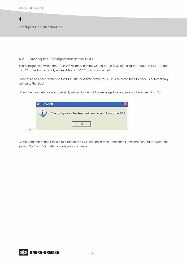
4.2 Storing the Configuration in the ECU
The configuration within the ECUtalk® memory can be written to the ECU by using the “Write to ECU” button (Fig. 21). The button is only accessible if a TIM G2 unit is connected.
Once a file has been written to the ECU, the next time “Write to ECU” is selected the PIN code is automatically written to the ECU.
When the parameters are successfully written to the ECU, a message box appears on the screen (Fig. 23).
Fig. 23
Some parameters don’t take effect before the ECU has been reset, therefore it is recommended to switch the ignition “Off” and “On” after a configuration change

21
5
E C U t a l k ® D i a g n o s t i c G u i d e f o r T I M G 2
E r r o r H a n d l i n g
Will delete memorized faults in the TIM G2 memory.
Will refresh the display and run the error detection routines again.
Fig. 24
5. Error Handling
Selecting the “Error Handling” button in the tool bar opens the error screen (Fig. 24).
Code DTC (Diagnostic Trouble Code) delivered from the TIM G2 ECU
Description Gives a short text describing the problem
The screen shows the following information:
The underlying buttons carry out the following action:

22
6
U s e r M a n u a l
D y n a m i c M e n u S e t t i n g
6. Dynamic Menu Setting
ECUtalk® for TIM G2 has the ability to redefine the order of the items displayed on the initial menu of TIM G2 using the “Menu Setting” button (Fig. 25).
Fig. 25
The “Menu setting” button will open the “Configurable Menu Settings” window (Fig. 26).
Fig. 26
The right side of the window shows the complete list of all available menu entries.The left side shows the current configured list in TIM G2.Using the arrows between the two sections, menu entries in the complete list can be added to or removed from the left side.The order of menu entries on the left side can be changed by selecting an item and using the up and down arrows displayed at the left side of this column.

2�
6
E C U t a l k ® D i a g n o s t i c G u i d e f o r T I M G 2
D y n a m i c M e n u S e t t i n g
6.1 Virtual Switches
Configuration with ECUtalk®:
Any function configured in TEBS G2 that use a switch and is assigned to TIM via „Current configurable menu“ can be actuated by the buttons on the TIM’s user interface.
If TEBS G2 offers ADL functionality with ADL Input control and a TIM G2 is available too, the buttons of the TIM’s control panel may be used for ADL Input control instead of adding further switches to the trailer chassis. The relevant menu entries to be assigned to the left side of the “configurable menu settings” window are #ADL… , e.g. #ADL INA (Fig.26).
Also tri-state and analogue switches for ADL are supported. The up button of the TIM user interface will increase the value with each actuation, while the down button will decrease the value each time. In case of analogue switches either of the buttons have to be kept pressed until the required value is reached.
Usage with TIM: Digital Switch:
Use the up and down buttons of the TIM control panel to scroll between the functions and the return button to switch the ADL function on and off.
Tri-state and Analogue Switches:
Use the up and down buttons of the TIM control panel to scroll between the functions and the return button to activate the switch. Activation is indicated with an asterisk (*). When activated use the up and down buttons again to modify the state of the switch. Use the return button again to deactivate the switch.
It is possible to assign new names to the #ADL Input on and off states, in the menu of the TIM G2 user interface. E.g. #ADL INA ON could be renamed to Enable TH, see also next chapter.
Also it is possible to assign new names to the #ADL Tri-state Input pull-up, pull-down and off states.
In case of an #ADL Analogue Input the name of the function can be renamed instead of its states.
Special settings for virtual switches
With TIM G2 application program version 10.71 or higher a new setting for virtual switches is introduced.Here you can configure if the switch is momentary or permanent and if it will keep its state after ignition OFF/ ON or not.
Selecting the “OK” button confirms the current settings, selecting “Cancel” drops any last changes.Selecting “Don’t show load histogram” check box hides the “Load history” menu item on the TIM’s screen. This modification comes into effect after an ECU reset.
Configured type Effect
Momentary = No The state stays “switched “after the button is released
Momentary = Yes The state is reset after the button is released
Volatile = No Switched status will be kept after ignition OFF/ON
Volatile = Yes Status will be reset after ignition OFF/ON

2�
6
U s e r M a n u a l
D y n a m i c M e n u S e t t i n g
6.2 Editing of Menu entries
ECUtalk® for TIM G2 PC diagnostics allows editing of the menu names shown in TIM G2.
If an editable menu item in Fig. 26 is double clicked a new dialogue window opens (Fig. 28) offering the possibility to edit both the “ON” and “OFF” menu names. Depending on the Windows language/country setting this table will look different.
Fig. 28
If the setting is not accessible it means that the current setting is a must for this function and therefore cannot be changed.
Fig. 27
2�
7
E C U t a l k ® D i a g n o s t i c G u i d e f o r T I M G 2
T I M G 2 M e n u L a n g u a g e P a c k
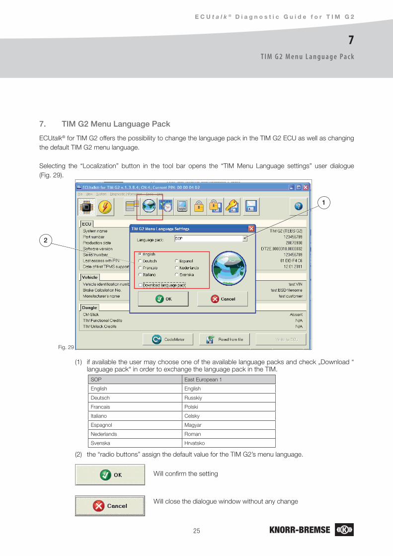
Will confirm the setting
Will close the dialogue window without any change
Fig. 29
7. TIM G2 Menu Language Pack
ECUtalk® for TIM G2 offers the possibility to change the language pack in the TIM G2 ECU as well as changing the default TIM G2 menu language.
Selecting the “Localization” button in the tool bar opens the “TIM Menu Language settings” user dialogue (Fig. 29).
(1) if available the user may choose one of the available language packs and check „Download “ language pack“ in order to exchange the language pack in the TIM.
(2) the “radio buttons” assign the default value for the TIM G2’s menu language.
2
1
SOP East European 1
English English
Deutsch Russkiy
Francais Polski
Italiano Celsky
Espagnol Magyar
Nederlands Roman
Svenska Hrvatsko

2�
8
U s e r M a n u a l
T i m e Z o n e S e t t i n g s
Will confirm the setting
Will close the dialogue window without any change
Fig. 30
8. Time Zone Settings
ECUtalk® for TIM G2 offers the possibility to program a time zone offset for the real time clock in order to adjust the TIM G2’s time display to the local region. The default time zone is GMT.
Selecting the “Time Zone” button allows the time zone to be adjusted in 1 hour steps between GMT -12 and GMT+12 (Fig. 30).

2�
9
E C U t a l k ® D i a g n o s t i c G u i d e f o r T I M G 2
C o n v e r s i o n t o H a n d h e l d
Will decrement the “Credits” in the WIBU Key by 10
Will close the dialogue window without any change
Fig. 31
9. Conversion to Handheld
If a WIBU Key is connected which holds enough credits, the user can convert a standard TIM G2 to a handheld tool. In this case there is no longer any linkage between TIM G2 and TEBS G2 (Fig. 31).

2�
1 0
U s e r M a n u a l
T I M G 2 ‘s A d v a n c e d D a t a R e c o r d i n g H a n d l i n g
Will decrement the credit counter off the Dongle and enable TDR upload
Will close the user dialogue window without any change
Fig. 32
10.1 Enabling TDR
Enabling TDR Upload is only possible if the WIBU Box/U+ key is connected and shows enough credits.Enabling TDR Upload will decrement the credit counter on the WIBU key.
Selecting the “Lock” button (Fig. 32) in the tool bar will open a user dialogue (Fig. 33).
Fig. 33

2�
1 0
E C U t a l k ® D i a g n o s t i c G u i d e f o r T I M G 2
T I M G 2 ‘s A d v a n c e d D a t a R e c o r d i n g H a n d l i n g
10.2 Enabling TDR retrospectively
If TDR upload was not enabled directly after the trailer left the manufacturer’s plant, but is required to be enabled at a later point in time, then, if the TIM G2 holds an earlier lock date it will offer the possibility to enable the TIM G2 Upload from the current day’s date or from an earlier date (Fig. 34).
This retrospective TDR upload will decrement the Dongle’s credit by five.
Fig. 34
10.3 Upload TDR
If enabled, the TDR can be uploaded from the TIM G2 ECU and saved in s19 format to file. This file can be sent for interpretation to your local Knorr-Bremse contact and you will get the evaluated data including bar graphs and so on back
Fig. 35
To upload the TDR, follow the menu structure (Fig. 35).Diagnostic Information ->Advanced Data Recorder -> TDR Upload to S19
- select “TDR All” to upload the whole record. - select “TDR Specific Interval” to set a Start and Stop date (Fig. 36).

�0
1 0
U s e r M a n u a l
T I M G 2 ‘s A d v a n c e d D a t a R e c o r d i n g H a n d l i n g
Fig. 36
The above dialogue can also be called up by selecting the “save” button (Fig. 38).
Fig. 38
If the TDR was uploaded before, ECUtalk® shows a concerning hint with the end date of that TDR upload. (Fig. 37).
Fig. 37

�1
1 0
E C U t a l k ® D i a g n o s t i c G u i d e f o r T I M G 2
T I M G 2 ‘s A d v a n c e d D a t a R e c o r d i n g H a n d l i n g
10.4 Save data set
This “Save data set” menu Item (Fig. 39) is only for the use of Knorr-Bremse. If demanded a workshop can upload this information and send it to Knorr-Bremse.
Fig. 39
10.5 The TDR Password dialogue
If TDR has been enabled and e.g. a fleet manager wants only his people to access the TDR data, then he may enter a password in the user dialogue (Fig. 40), in order to protect the TDR data from being read by a non authorized person.
The dialogue window is called when the “Key” button is selected (Fig. 40).
Fig. 40
�2
1 1
U s e r M a n u a l
U n l o c k T I M
Fig. 41
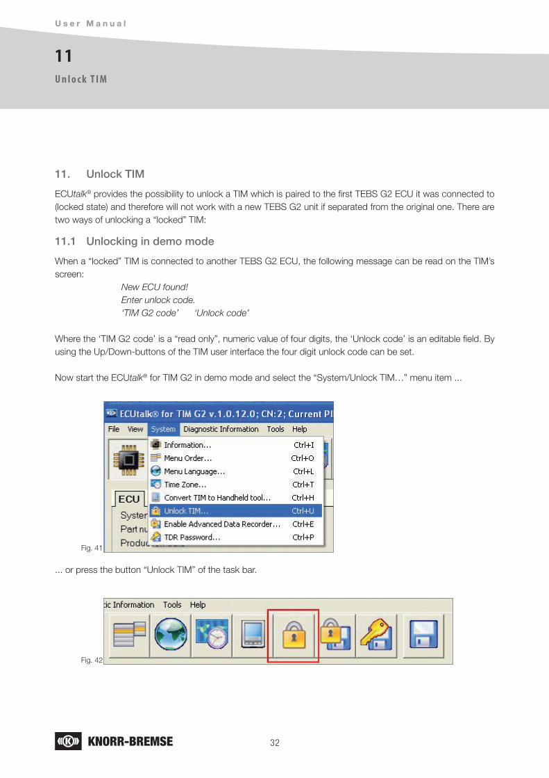
11. Unlock TIM
ECUtalk® provides the possibility to unlock a TIM which is paired to the first TEBS G2 ECU it was connected to (locked state) and therefore will not work with a new TEBS G2 unit if separated from the original one. There are two ways of unlocking a “locked” TIM:
11.1 Unlocking in demo mode
When a “locked” TIM is connected to another TEBS G2 ECU, the following message can be read on the TIM’s screen: New ECU found! Enter unlock code. ‘TIM G2 code’ ‘Unlock code’
Where the ‘TIM G2 code’ is a “read only”, numeric value of four digits, the ‘Unlock code’ is an editable field. By using the Up/Down-buttons of the TIM user interface the four digit unlock code can be set.
Now start the ECUtalk® for TIM G2 in demo mode and select the “System/Unlock TIM…” menu item ...
... or press the button “Unlock TIM” of the task bar.
Fig. 42

��
1 1
E C U t a l k ® D i a g n o s t i c G u i d e f o r T I M G 2
U n l o c k T I M
The following dialogue appears on the screen:
Fig. 43
Enter the four digits at “Enter TIM G2 code here:”, then press the “Generate” button. The next dialogue shows the number of required credits.
Fig. 44
Click “OK” to confirm the credit usage. Find your four digits PIN code in the dialogue.
Attention:
If you do not use it immediately then please save it, generating it again takes credits again.
Now type your PIN code value into the TIM. Use the TIM’s Up/Down buttons to set the digit’s value and step to the next digit. When all digits are set to the right value press the enter button. Now the TIM becomes locked to the new TEBS G2 ECU.

��
1 1
U s e r M a n u a l
U n l o c k T I M
11.2 Unlocking in real mode
Select the “System/Unlock TIM…” menu item from the application main menu.
If your TIM is locked to any TEBS G2 ECU the following dialogue appears on the screen:
Fig. 45
Click “OK” to confirm the credit usage. Your TIM is unlocked now. Be aware that next time when the TIM communicates with a TEBS G2 ECU it locks itself immediately to that particular TEBS module.
If your TIM is not locked to any TEBS G2 ECU the following dialogue appears on the screen:
Fig. 46

��
1 2
E C U t a l k ® D i a g n o s t i c G u i d e f o r T I M G 2
F l a s h
12. Flash
ECUtalk® provides the possibility to upgrade the TIM G2 application software. The upgrade process consists of the following steps:
Knorr-Bremse provides an ECUtalk® for TIM G2 installation package including the ECU flash update package or a separate flash update package − the so called “UpdatePackage” − which contains all necessary information and files.
Start this package installation and follow the instructions.
Start ECUtalk® for TIM G2 diagnostic software.
1.
2.
3.
Fig. 47
If the currently installed application software is corrupt for any reason the user is asked to enter the part number.
Because the system does not know if the current type of Software was TIM G2 for TEBS G2 or TIM G2 for TEBS4 (replacement for TIM1) both update packages are offered:
Fig. 48

��
1 2
U s e r M a n u a l
F l a s h
If your TIM G2 system needs to be updated then the next dialogue appears on the screen: 4.
Fig. 51
Fig. 49
In order not to download the wrong update package accidentally, the selected package is announced again and needs to be confirmed.
Fig. 50

��
1 2
E C U t a l k ® D i a g n o s t i c G u i d e f o r T I M G 2
F l a s h
Selecting the “Yes” button opens the flash report form.5.
Fig. 52
It is mandatory to fill out all empty fields. Otherwise the download process can’t start.6.
Fig. 53
When the form is complete press “OK” and save the file:7.
Fig. 54

��
1 2
U s e r M a n u a l
F l a s h
Please send this file per email to [email protected] .
This is the start point of the download process. During the process the following progress bars show the state of the download:
8.
9.
Fig. 55
Fig. 56
Fig. 57
In case of any error occurs during the previous step the next two dialogues show the error and the possible reasons:
10.
Fig. 58
Fig. 59

��
1 2
E C U t a l k ® D i a g n o s t i c G u i d e f o r T I M G 2
F l a s h
Please try to eliminate the problem and press “Reinitialize” to continue the download. Even if you press “Exit” you can continue the download later starting ECUtalk® for TIM G2. In both cases the following dialogue offers the possibility to continue the interrupted flash process:
Fig. 60
The following dialogue shows the end of a successful upgrade process:11.
Fig. 62
In case ECUtalk® identifies more then one interrupted flash sessions, the user needs to select the session he wants to continue.
Fig. 61

�0
1 2
U s e r M a n u a l
F l a s h
12.1 Replace a TIM1 (TIM G2 downgrade)
You can downgrade a TIM G2 to replace a TIM1 connected to a TEBS4 via K-Line.
To do so you need to exchange the application software by flashing it with the update package TIM G2 for TEBS4.
A TIM G2 can be downgraded under the following conditions:
1. The TIM G2 Module must be able to communicate via the K-Line, for validation ECUtalk® reads the part number of the currently connected TIM, the software version part of the number must match with V02 or higher.
2. The TIM G2 for TEBS4 ECU application update package must be found on the hard drive.
If those are fulfilled the user can select the flash TIM G2 for TEBS4 from the menu.
Selecting the function will start the Flash download sequence described in earlier in this chapter.
Fig. 63
Fig. 64

�1
1 3
E C U t a l k ® D i a g n o s t i c G u i d e f o r T I M G 2
C o d e M e t e r
13. CodeMeter
Applying for CodeMeter Sticks, TIM Functional Credits and/or TIM Unlock credits please contact your local Knorr-Bremse contact.Updating the Codemeter Stick.Please see the CodeMeter help for details.This is provided in the “CodeMeter User Help”. You can find it in the folder “Windows-Start-Menu/Programs/CodeMeter/Documentation/”.
Open the chapter “Licensing Field Activation System” to see the concerning help. Here you find detailed information about:
How to create the so called “CM Remote Contents file (WibuCmRaC file)” for credit update directly in the Windows Explorer or with the “Codemeter control centre”.
How to use the (CM Remote Update file (WibuCmRaU file) to update the credits on your stick directly in the Windows Explorer or with the “Codemeter control center”.
The “Codemeter Control center” program is installed together with ECUtalk® for TIM G2 on your PC.
•
•
Fig. 65
Selecting the button “CodeMeter” in ECUtalk® for TIM G2 will start the application.
Fig. 66

�2
1 4
U s e r M a n u a l
To o l s
14. Tools
Selecting “Tools” and then “Data Logger” in the main menu (Fig. 59) will open the “Data Logger” screen (Fig. 60).
Fig. 67
Will clear the current log
Will save the current log to file
Will start the search function
Will start the logging (“play” button toggles to a “stop” button). Clicking the “stop” button will stop the logging (“stop” button toggles back to a “play” button)
Fig. 68

��
E C U t a l k ® D i a g n o s t i c G u i d e f o r T I M G 2
Notes

Knorr-Bremse Group
Europe – Africa
Austria Knorr-Bremse GmbHSysteme für NutzfahrzeugeMödlingTel: +43 2236 409-2436Fax: +43 2236 409-2434
BelgiumKnorr-Bremse Benelux B.V.B.A.Heist-op-den-BergTel: +32 1525 7900Fax: +32 1524 9240
Czech RepublicKnorr-Bremse Systémy prouzitková vozidla, CR, s.r.o.LiberecTel: +420 482 363-611Fax: +420 482 363-711
France Knorr-BremseSystèmes pour Véhicules Utilitaires FranceLisieux CedexTel: +33 2 3132 1200Fax: +33 2 3132 1303
Germany Hasse & Wrede GmbHBerlin Tel: +49 30 9392-3101Fax: +49 30 7009-0811
Germany Knorr-Bremse Systeme für Nutzfahrzeuge GmbHBerlin Tel: +49 180 223-7637 Fax: +49 30 9392-3426
HungaryKnorr-Bremse Fékrendszerek Kft.Kecskemét Tel: +36 76 511 100Fax: +36 76 481 100
ItalyKnorr-Bremse Sistemi per Autoveicoli Commerciali S.p.A.Arcore Tel: +39 039 6075-1Fax: +39 039 6075-435
Netherlands Knorr-Bremse Benelux B.V.B.A.Mydrecht Tel: +31 297 239-330Fax: +31 297 239-339
PolandKnorr-Bremse Polska SfN Sp. z o.o.WarsawTel: +48 22 887-3870Fax: +48 22 531-4170
RussiaKnorr-Bremse RUSNizhniy NovgorodTel: +7 831 220-5687Fax: +7 831 220-5688
RussiaKnorr-BremseSysteme für Nutzfahrzeuge GmbHMoscowTel: +7 495 234-4995Fax: +7 495 234-4996
South Africa Knorr-Bremse S.A. Pty. Ltd. Kempton Park Tel: +27 11 961-7800Fax: +27 11 975-8249
SpainBost Ibérica, S.L.Irun (Guipuzcoa) Tel: +34 902 100-569Fax: +34 943 614-063
Sweden Knorr-BremseSystem for Tunga Fordon ABLundTel: +46 46 440 0105Fax: +46 46 148971
SwitzerlandKnorr-BremseSysteme für Nutzfahrzeuge GmbHBassersdorf Tel: +41 44 888 77-55Fax: +41 44 888 77-50
Turkey Knorr-BremseTicari Araç Fren Sistemleri Tic. Ltd. Sti.Findikli - IstanbulTel: +90 212 293-4742Fax: +90 212 293-4743
United Kingdom Knorr-Bremse Systems for Commercial Vehicles Ltd.BristolTel: +44 117 9846-100Fax: +44 117 9846-101
America
Brazil Knorr-BremseSistemas para Veículos Comerciais Brasil Ltda.São Paulo Tel: +55 11 5681 1104Fax: +55 11 5686 3905
USABendix Commercial Vehicle Systems LLC Elyria, OH Tel: +1 440 329-9100Fax: +1 440 329-9105
Asia – Australia
AustraliaKnorr-Bremse Australia Pty. Ltd. Granville NSWTel: +61 2 8863-6500Fax: +61 2 8863-6510
China Knorr-Bremse Brake Equipment (Shanghai) Co. Ltd. ShanghaiTel: +86 21 3858-5800Fax: +86 21 3858-5900
China Knorr-Bremse Asia Pacific (Holding) LimitedCommercial Vehicle Systems DivisionHong Kong Tel: +852 3657-9800Fax: +852 3657-9901
IndiaKnorr-BremseSystems for Commercial Vehicles India Private Ltd.PuneTel: +91 20 6674-6800Fax: +91 20 6674-6899
JapanKnorr-Bremse Commercial Vehicle Systems Japan Ltd.SaitamaTel: +81 49 273-9155Fax: +81 49 282-8601
Korea Knorr-Bremse Korea Ltd. Truck Brake DivisionSeoul Tel: +82 2 2273-1182Fax: +82 2 2273-1184
Head Office
Knorr-Bremse Systeme für Nutzfahrzeuge GmbHMoosacher Strasse 80 80809 Munich Germany Tel: +49 89 3547-0 Fax: +49 89 3547-2767www.knorr-bremseCVS.com
The i
nform
ation
conta
ined h
erein
is sub
ject to
alter
ation
with
out n
otice
and t
heref
ore m
ay no
t be t
he la
test re
lease.
Plea
se ch
eck o
ur we
bsite
www
.knorr
-brem
seCVS
.com
for th
e late
st up
date
or co
ntact
your
local
Knorr
-Brem
se rep
resen
tative
. The
figura
tive m
ark “K
” and
the t
radem
arks K
NORR
and K
NORR
-BRE
MSE a
re reg
istere
d in t
he na
me of
Knorr
-Brem
se AG
. Add
itiona
l term
s and
cond
itions
apply
; plea
se ref
er to
our w
ebsit
e kno
rr-bre
mseC
VS.co
m for
full D
isclai
mer.
Note:
If ser
vice w
ork is
carrie
d out
on a
vehic
le ba
sed on
infor
matio
n prov
ided h
erein,
it is t
he re
spon
sibilit
y of th
e work
shop
to en
sure
the ve
hicle
is full
y test
ed an
d in f
ull fu
nctio
nal o
rder b
efore
the ve
hicle
is retu
rned i
nto se
rvice.
Knorr
-Brem
se
acce
pts no
liabil
ity fo
r prob
lems c
aused
as a
result
of ap
propri
ate te
sts no
t bein
g carr
ied ou
t.Co
pyrig
ht ©
Knorr
-Brem
se AG
- all r
ights
reserv
ed, in
cludin
g ind
ustria
l prop
erty r
ights
appli
cation
s. Kno
rr-Bre
mse A
G reta
ins an
y pow
er of
dispo
sal, su
ch as
for c
opyin
g and
trans
ferrin
g.
Doc. No. Y051983 (EN - Rev. 003)October 2011
C o m m e r c i a l V e h i c l e S y s t e m s