dywidag marine tie rods – smooth bars & walings · 2019-04-30 · dywidag marine tie rods –...
TRANSCRIPT
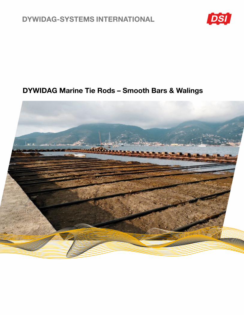
DYWIDAG Marine Tie Rods – Smooth Bars & Walings
2
Contents
General Information ������������������������������������������������������������������������������������������������������������������������������������������������������������������������������ 4Fields of Applications ����������������������������������������������������������������������������������������������������������������������������������������������������������������������� 4Overview of Steel Grades ���������������������������������������������������������������������������������������������������������������������������������������������������������������� 5Steel Properties�������������������������������������������������������������������������������������������������������������������������������������������������������������������������������� 5Thread Creation ������������������������������������������������������������������������������������������������������������������������������������������������������������������������������� 6Key Advantages of Rolled Threads �������������������������������������������������������������������������������������������������������������������������������������������������� 6ULS Tie Rod Design According to DIN EN 1993-5 �������������������������������������������������������������������������������������������������������������������������� 8Design Example ������������������������������������������������������������������������������������������������������������������������������������������������������������������������������� 9
Tie Rod Types ������������������������������������������������������������������������������������������������������������������������������������������������������������������������������������� 10Tie Rods with Upset and Rolled Threads acc� to EAU 2014 kt 0�55 ����������������������������������������������������������������������������������������������� 10Tie Rods with Upset and Rolled Threads acc� to DIN EN 1993-5 �������������������������������������������������������������������������������������������������� 12Tie Rods with Rolled Threads acc� to DIN EN 1993-5 kt 0�9 ���������������������������������������������������������������������������������������������������������� 14Eye Rods kt 0�6 ������������������������������������������������������������������������������������������������������������������������������������������������������������������������������ 16
Tie Rod Connection Elements ������������������������������������������������������������������������������������������������������������������������������������������������������������ 18Turnbuckles for Tie Rods ��������������������������������������������������������������������������������������������������������������������������������������������������������������� 18Couplers for Tie Rods �������������������������������������������������������������������������������������������������������������������������������������������������������������������� 18Hinged Turnbuckles for Tie Rods ��������������������������������������������������������������������������������������������������������������������������������������������������� 20Hexagonal Nuts* ���������������������������������������������������������������������������������������������������������������������������������������������������������������������������� 20Domed Nuts* ���������������������������������������������������������������������������������������������������������������������������������������������������������������������������������� 20Shackle Joint for Tie Rods ������������������������������������������������������������������������������������������������������������������������������������������������������������� 22Rocker Plate for Tie Rods �������������������������������������������������������������������������������������������������������������������������������������������������������������� 22Threaded Rocker Plate for Tie Rods ���������������������������������������������������������������������������������������������������������������������������������������������� 22Universal Joints for Tie Rods ��������������������������������������������������������������������������������������������������������������������������������������������������������� 24Universal Joints at Waling for Tie Rods ������������������������������������������������������������������������������������������������������������������������������������������ 24
Tie Rod and Waling Joints ������������������������������������������������������������������������������������������������������������������������������������������������������������������ 26Rear Plate for DSI 355 Tie Rods acc� to 1993-5 with kt 0�9 in S355 ����������������������������������������������������������������������������������������������� 26Rear Plate for DSI 460 Tie Rods acc� to 1993-5 with kt 0�9 in S355 ����������������������������������������������������������������������������������������������� 28Rear Plate for DSI 500 Tie Rods acc� to 1993-5 with kt 0�9 in S355 ����������������������������������������������������������������������������������������������� 30Rear Plate for DSI 720 Tie Rods ����������������������������������������������������������������������������������������������������������������������������������������������������� 32T-Connections for Tie Rods* ���������������������������������������������������������������������������������������������������������������������������������������������������������� 34T-Connections in Combined Sheet Piling for Anchors* ������������������������������������������������������������������������������������������������������������������ 34
Typical Complete Tie Rod Systems ���������������������������������������������������������������������������������������������������������������������������������������������������� 36Compensate for Shallow Angles of up to max� 5° �������������������������������������������������������������������������������������������������������������������������� 36Dead Man��������������������������������������������������������������������������������������������������������������������������������������������������������������������������������������� 36Combined Sheet Piling with Tubular Piles �������������������������������������������������������������������������������������������������������������������������������������� 36Combined Sheet Piling when using Grade DSI 720 ����������������������������������������������������������������������������������������������������������������������� 36Anchors Connected to Tubular Piles ���������������������������������������������������������������������������������������������������������������������������������������������� 37Heavy-Duty Walls with Steel Sections ������������������������������������������������������������������������������������������������������������������������������������������� 37Alternative Tubular Pile Connection Option Permitting Rotational Movement in all Directions ������������������������������������������������������ 37
Walings ����������������������������������������������������������������������������������������������������������������������������������������������������������������������������������������������� 38Waling Splice Joint ������������������������������������������������������������������������������������������������������������������������������������������������������������������������� 39Waling Bracket ������������������������������������������������������������������������������������������������������������������������������������������������������������������������������� 40Waling Bolt with Head and Nut ������������������������������������������������������������������������������������������������������������������������������������������������������ 41Waling Stud with two Nuts ������������������������������������������������������������������������������������������������������������������������������������������������������������� 42
Appendix �������������������������������������������������������������������������������������������������������������������������������������������������������������������������������������������� 43List of Standards and Directives ���������������������������������������������������������������������������������������������������������������������������������������������������� 43
3

General Information
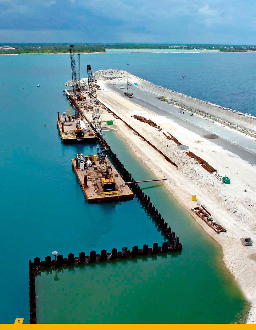
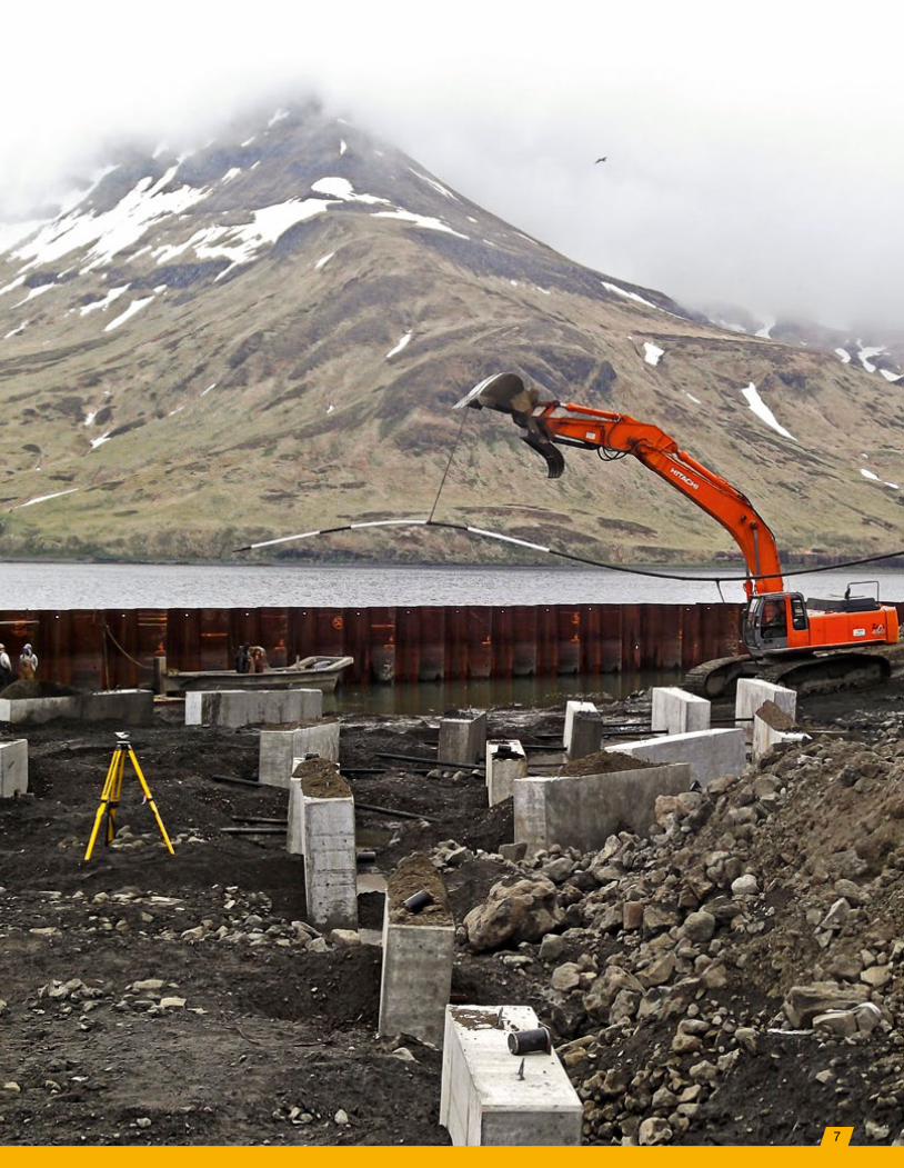
Deep vertical shoring systems for marine structures such as sheet pile walls often require additional anchors which support a specific layer of the shoring wall� These anchors are also referred to as tie rods� They transfer the supportive forces at the connection
with the sheet pile wall via tension loads either to a dead man anchorage or to the other shoring wall side in the case of wharf sheet pile boxes� Typically, the horizontal reaction forces are transferred from the sheet pile walls first to a waling beam and then from the waling system
to the tie rods� This setup leads to a more distributed load transfer and an additional stiffening and alignment of the sheet pile wall compared to a solution in which the tie rods are directly connected to the sheet pile wall�
Fields of Applications
Tie Back Retaining Wall with Dead Man Bracing for Grade Separation
Tie Rods for Sheet Pile Constructed Wharf Roadway Embankment Stabilization
4

Steel Properties
DSI 355
■ Typcial structural steel acc� to EN 10025
■ Forged materials available in all lengths
■ CE marking and declaration possible
DSI 460
■ Fine-grained structural steel acc� to EN 10025
■ Easy-to-process steel grade limit acc� to EN 1993-5
■ Forged materials available in all lengths
■ CE marking and declaration possible
DSI 500
■ Steel modified from DSI 460 ■ All further properties as for DSI 460 ■ Forged materials available in all lengths
■ CE marking and declaration possible
DSI 720
■ Maximum length up to 12m ■ CE marking upon request ■ Forged materials available up to 12 m length
■ Classic QT steel acc� to DIN EN 10083-1 and quenched and tempered to achieve grade 10�9 acc� to EN ISO 898-1
General Information
Overview of Steel Grades
Color Code Steel Grade Diameter Fy Fua
[ØD1] [N/mm2] [N/mm2]
DSI 355 M39 - M160 355 510
DSI 460 M39 - M160 460 640
DSI 500 M39 - M160 500 680
DSI 720 M39 - M160 720 900
Fy = Characteristic Yield Stress Fua = Characteristic Failure Stress
Steel Characteristics
The steel used for our marine tie rods is based on the continuous casting method production leading to a homogenous resistance behavior over the entire steel section area�
5
General Information
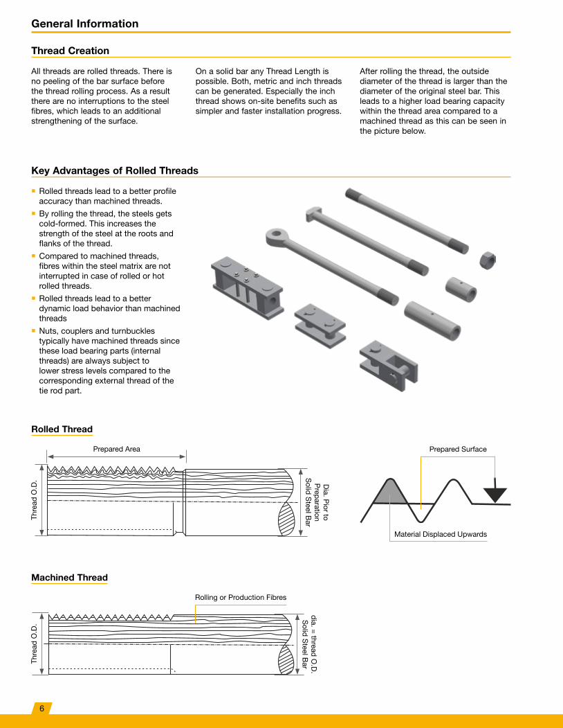
Thread Creation
All threads are rolled threads� There is no peeling of the bar surface before the thread rolling process� As a result there are no interruptions to the steel fibres, which leads to an additional strengthening of the surface�
On a solid bar any Thread Length is possible� Both, metric and inch threads can be generated� Especially the inch thread shows on-site benefits such as simpler and faster installation progress�
After rolling the thread, the outside diameter of the thread is larger than the diameter of the original steel bar� This leads to a higher load bearing capacity within the thread area compared to a machined thread as this can be seen in the picture below�
Rolled Thread
Material Displaced Upwards
Prepared Area
Thre
ad O
�D� D
ia� Pior to
Preparation
Solid S
teel Bar
Prepared Surface
Machined Thread
Thre
ad O
�D�
dia� = thread O
�D�
Solid S
teel Bar
Rolling or Production Fibres
Key Advantages of Rolled Threads
■ Rolled threads lead to a better profile accuracy than machined threads�
■ By rolling the thread, the steels gets cold-formed� This increases the strength of the steel at the roots and flanks of the thread�
■ Compared to machined threads, fibres within the steel matrix are not interrupted in case of rolled or hot rolled threads�
■ Rolled threads lead to a better dynamic load behavior than machined threads
■ Nuts, couplers and turnbuckles typically have machined threads since these load bearing parts (internal threads) are always subject to lower stress levels compared to the corresponding external thread of the tie rod part�
6
7
General Information
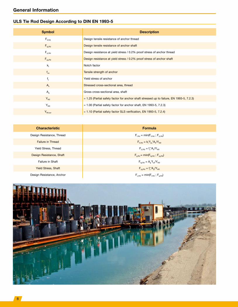
ULS Tie Rod Design According to DIN EN 1993-5
Symbol Description
Ftt,Rd Design tensile resistance of anchor thread
Ftg,Rd Design tensile resistance of anchor shaft
Fyt,Rd Design resistance at yield stress / 0�2% proof stress of anchor thread
Fyg,Rd Design resistance at yield stress / 0�2% proof stress of anchor shaft
kt Notch factor
fua Tensile strength of anchor
fy Yield stress of anchor
As Stressed cross-sectional area, thread
Ag Gross cross-sectional area, shaft
YM2 = 1�25 (Partial safety factor for anchor shaft stressed up to failure, EN 1993-5, 7�2�3)
YM0 = 1�00 (Partial safety factor for anchor shaft, EN 1993-5, 7�2�3)
YMt,ser = 1�10 (Partial safety factor SLS verification, EN 1993-5, 7�2�4)
Characteristic Formula
Design Resistance, Thread Ft,Rd = min(Ftt,Rd ; Fyt,Rd)
Failure in Thread Ftt,Rd = kt*fua*As/YM2
Yield Stress, Thread Fyt,Rd = fy*As/YM0
Design Resistance, Shaft Fg,Rd = min(Ftg,Rd ; Fyg,Rd)
Failure in Shaft Ftg,Rd = Ag*fua/YM2
Yield Stress, Shaft Fyg,Rd = fy*Ag/YM0
Design Resistance, Anchor Fu,Rd = min(Ft,Rd ; Fg,Rd)
8

General Information
Design Example
Design Conditions
■ Ultimate Limit State (ULS) load for tie rod ■ FEd = 2,500[kN]
■ Serviceability Limit State (SLS) load ■ Ft,ser = 1,600[kN]
■ Tie bar length ■ 40m
■ Tie bar elongation limit (SLS) ■ 80[mm]
■ Design life of structure ■ 50 years
■ Notching factor in thread area – use recommended value kt = 0�6 (see BS EN 1993-5 NA A1)
Serviceability Limit State (SLS) Check acc. to EN 1993-5, 7.2.4
Elongation under SLS loading condition�
1� Stress in shaft, σt = Ft,ser/Ag = 1,600 * 103/5,153 = 310[N/mm²]
2� Elongation = σt * Length/E-Modul = 310 * 400/2,100 = 59[mm] < 80[mm]
Note: If the elongation is exceeding the limit of 80[mm], try a larger diameter of a less grade�
3� Yield Stress, Thread = Fyt,Rd = fy * min(AS;Ag)/γMt,ser = 500 * 7,755/(1�1 * 10³) = 3,525[kN] > 1,600[kN] = Ft,ser
Ultimate Limit State (ULS) check acc. to EN 1993-5, 7.2.3
1� Design tensile resistance = Ft,Rd = 2,531[kN] > 2,500[kN] = FEd
Tie Rod Type Selection
The required minimum anchor size depends on the design tensile resistance Ft,Rd = min(Ftt,Rd ; Fyt,Rd) according to EN 1993-5, 7�2�3 The used partial safety factor for the design level are given in the formulation above� The UK decision for the values of the thread notch factor, given in BS EN 1993-5, NA Table A1 Subclause 7�2�3 (2) are:
■ The recommended value for kt is kt = 0�6"� This is motivated for cases where possible bending in the anchor as an effect of actions is not made explicit�
■ Only in cases where the structural detailing of the location where the anchor rod is joined to the wall is such that bending moments are avoided at that location, the recommended value for kt may be chosen as kt = 0�9"�
Based on the design resistance values of tie rods with rolled threads, tie rod type M105/81 is chosen to fit directly the design tensile resistance conditions in the Ultimate Limit State� ■ Thread
■ M105 (stress area AS: 7,755[mm²]) ■ Shaft
■ 81[mm] (stress area Ag: 5,153[mm²]) ■ Yield Stress of the Anchor
■ fy = 500[N/mm²] ■ Tensile Strength of Anchor
■ fua = 680[N/mm²]
Length of Anchor = 40m
FEd
FEd
Notching Factor kt = 0�6 acc� to BS EN 1993-5 NA A
9
Tie Rod Types
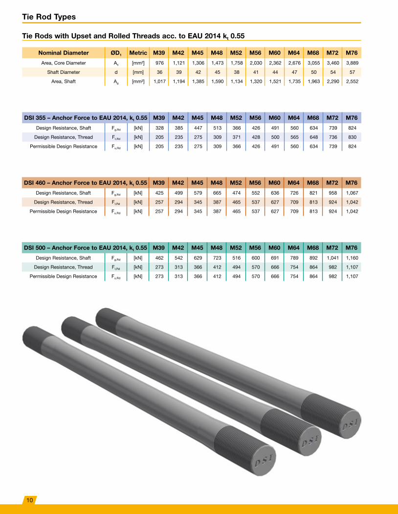
Tie Rods with Upset and Rolled Threads acc. to EAU 2014 kt 0.55
Nominal Diameter ØD1 Metric M39 M42 M45 M48 M52 M56 M60 M64 M68 M72 M76
Area, Core Diameter As [mm²] 976 1,121 1,306 1,473 1,758 2,030 2,362 2,676 3,055 3,460 3,889
Shaft Diameter d [mm] 36 39 42 45 38 41 44 47 50 54 57
Area, Shaft Ag [mm²] 1,017 1,194 1,385 1,590 1,134 1,320 1,521 1,735 1,963 2,290 2,552
DSI 355 – Anchor Force to EAU 2014, kt 0.55 M39 M42 M45 M48 M52 M56 M60 M64 M68 M72 M76
Design Resistance, Shaft Fg,Rd [kN] 328 385 447 513 366 426 491 560 634 739 824
Design Resistance, Thread Ft,Rd [kN] 205 235 275 309 371 428 500 565 648 736 830
Permissible Design Resistance Fu,Rd [kN] 205 235 275 309 366 426 491 560 634 739 824
DSI 460 – Anchor Force to EAU 2014, kt 0.55 M39 M42 M45 M48 M52 M56 M60 M64 M68 M72 M76
Design Resistance, Shaft Fg,Rd [kN] 425 499 579 665 474 552 636 726 821 958 1,067
Design Resistance, Thread Ft,Rd [kN] 257 294 345 387 465 537 627 709 813 924 1,042
Permissible Design Resistance Fu,Rd [kN] 257 294 345 387 465 537 627 709 813 924 1,042
DSI 500 – Anchor Force to EAU 2014, kt 0.55 M39 M42 M45 M48 M52 M56 M60 M64 M68 M72 M76
Design Resistance, Shaft Fg,Rd [kN] 462 542 629 723 516 600 691 789 892 1,041 1,160
Design Resistance, Thread Ft,Rd [kN] 273 313 366 412 494 570 666 754 864 982 1,107
Permissible Design Resistance Fu,Rd [kN] 273 313 366 412 494 570 666 754 864 982 1,107
10

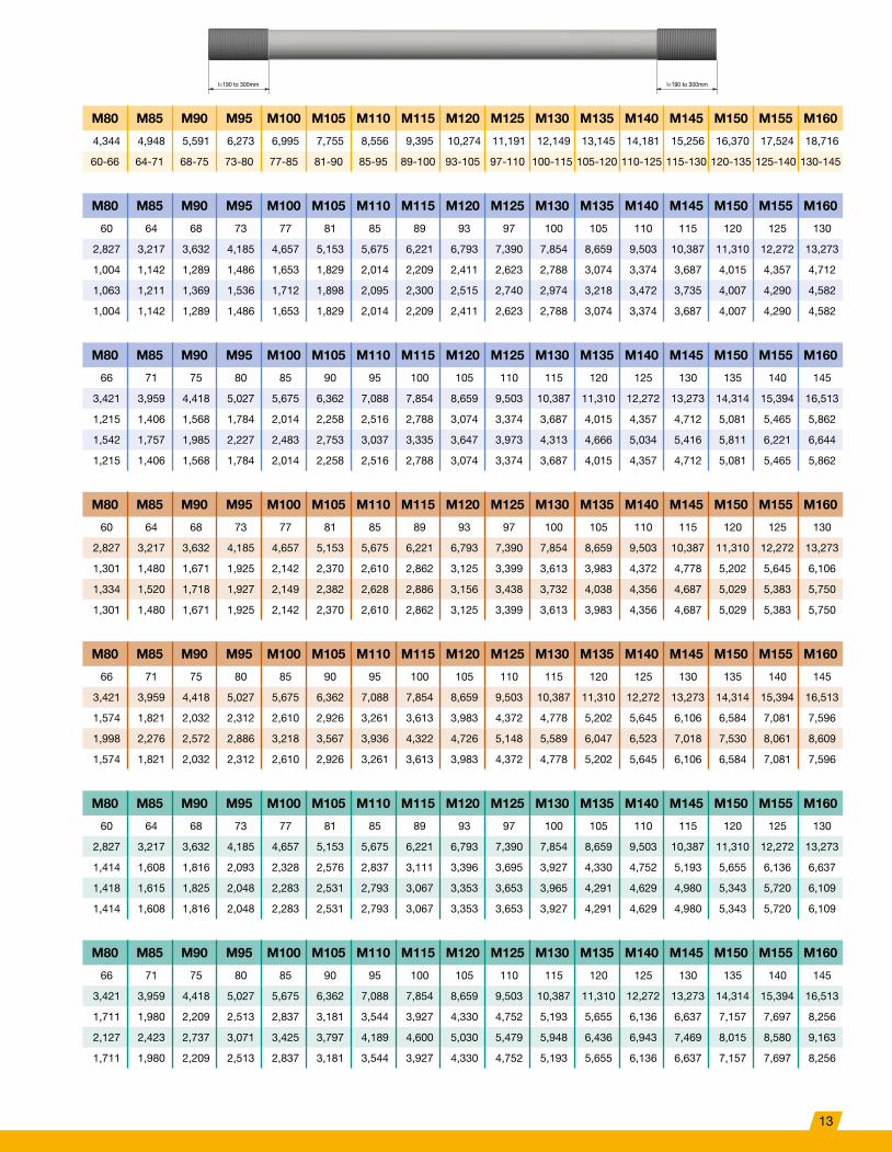
M80 M85 M90 M95 M100 M105 M110 M115 M120 M125 M130 M135 M140 M145 M150 M155 M160
4,344 4,948 5,591 6,273 6,995 7,755 8,556 9,395 10,274 11,191 12,149 13,145 14,181 15,256 16,370 17,524 18,716
60 64 68 73 77 81 85 89 93 97 101 105 109 113 118 123 127
2,827 3,217 3,632 4,185 4,657 5,153 5,675 6,221 6,793 7,390 8,012 8,659 9,331 10,029 10,936 11,882 12,668
M80 M85 M90 M95 M100 M105 M110 M115 M120 M125 M130 M135 M140 M145 M150 M155 M160
912 1,038 1,172 1,351 1,503 1,663 1,831 2,008 2,192 2,385 2,586 2,795 3,011 3,237 3,529 3,835 4,088
930 1,062 1,204 1,354 1,512 1,680 1,857 2,042 2,236 2,439 2,651 2,871 3,101 3,339 3,586 3,842 4,106
912 1,038 1,172 1,351 1,503 1,663 1,831 2,008 2,192 2,385 2,586 2,795 3,011 3,237 3,529 3,835 4,088
M80 M85 M90 M95 M100 M105 M110 M115 M120 M125 M130 M135 M140 M145 M150 M155 M160
1,182 1,345 1,519 1,750 1,947 2,155 2,373 2,602 2,841 3,090 3,350 3,621 3,902 4,194 4,573 4,969 5,297
1,167 1,333 1,510 1,699 1,898 2,108 2,330 2,562 2,806 3,061 3,326 3,603 3,891 4,190 4,500 4,821 5,153
1,167 1,333 1,510 1,699 1,898 2,108 2,330 2,562 2,806 3,061 3,326 3,603 3,891 4,190 4,500 4,821 5,153
M80 M85 M90 M95 M100 M105 M110 M115 M120 M125 M130 M135 M140 M145 M150 M155 M160
1,285 1,462 1,651 1,902 2,117 2,342 2,579 2,828 3,088 3,359 3,642 3,936 4,242 4,559 4,971 5,401 5,758
1,240 1,416 1,605 1,805 2,017 2,240 2,476 2,723 2,981 3,252 3,534 3,828 4,134 4,452 4,781 5,122 5,475
1,240 1,416 1,605 1,805 2,017 2,240 2,476 2,723 2,981 3,252 3,534 3,828 4,134 4,452 4,781 5,122 5,475
11

Tie Rod Types
Tie Rods with Upset and Rolled Threads acc. to DIN EN 1993-5
Nominal Diameter ØD1 Metric M39 M42 M45 M48 M52 M56 M60 M64 M68 M72 M76
Stressed Area, Thread As [mm²] 976 1,121 1,306 1,473 1,758 2,030 2,362 2,676 3,055 3,460 3,889
Shaft Diameter d [mm] 36 39 42 45 38-39 41-42 44-46 47-50 50-54 54-58 57-62
DSI 355 – Anchor Force to EN 1993-5, kt 0.6 M39 M42 M45 M48 M52 M56 M60 M64 M68 M72 M76
Shaft Diameter d [mm] 36 39 42 45 38 41 44 47 50 54 57
Area, Shaft Ag [mm²] 1,018 1,195 1,385 1,590 1,134 1,320 1,521 1,735 1,963 2,290 2,552
Design Resistance, Shaft Fg,Rd [kN] 361 424 492 565 403 469 540 616 697 813 906
Design Resistance, Thread Ft,Rd [kN] 239 274 320 361 430 497 578 655 748 847 952
Permissible Design Resistance Fu,Rd [kN] 239 274 320 361 403 469 540 616 697 813 906
DSI 355 – Anchor Force to EN 1993-5, kt 0.9 M39 M42 M45 M48 M52 M56 M60 M64 M68 M72 M76
Shaft Diameter d [mm] 36 39 42 45 39 42 46 50 54 58 62
Area, Shaft Ag [mm²] 1,018 1,195 1,385 1,590 1,195 1,385 1,662 1,963 2,290 2,642 3,019
Design Resistance, Shaft Fg,Rd [kN] 361 424 492 565 424 492 590 697 813 938 1,072
Design Resistance, Thread Ft,Rd [kN] 346 398 464 523 624 721 839 950 1,085 1,228 1,381
Permissible Design Resistance Fu,Rd [kN] 346 398 464 523 424 492 590 697 813 938 1,072
DSI 460 – Anchor Force to EN 1993-5, kt 0.6 M39 M42 M45 M48 M52 M56 M60 M64 M68 M72 M76
Shaft Diameter d [mm] 36 39 42 45 38 41 44 47 50 54 57
Area, Shaft Ag [mm²] 1,018 1,195 1,385 1,590 1,134 1,320 1,521 1,735 1,963 2,290 2,552
Design Resistance, Shaft Fg,Rd [kN] 468 550 637 732 522 607 699 798 903 1,054 1,174
Design Resistance, Thread Ft,Rd [kN] 300 344 401 453 540 624 726 822 938 1,063 1,195
Permissible Design Resistance Fu,Rd [kN] 300 344 401 453 522 607 699 798 903 1,054 1,174
DSI 460 – Anchor Force to EN 1993-5, kt 0.9 M39 M42 M45 M48 M52 M56 M60 M64 M68 M72 M76
Shaft Diameter d [mm] 36 39 42 45 39 42 46 50 54 58 62
Area, Shaft Ag [mm²] 1,018 1,195 1,385 1,590 1,195 1,385 1,662 1,963 2,290 2,642 3,019
Design Resistance, Shaft Fg,Rd [kN] 468 550 637 732 550 637 764 903 1,054 1,215 1,389
Design Resistance, Thread Ft,Rd [kN] 449 516 601 678 809 934 1,087 1,231 1,405 1,592 1,789
Permissible Design Resistance Fu,Rd [kN] 449 516 601 678 550 637 764 903 1,054 1,215 1,389
DSI 500 – Anchor Force to EN 1993-5, kt 0.6 M39 M42 M45 M48 M52 M56 M60 M64 M68 M72 M76
Shaft Diameter d [mm] 36 39 42 45 38 41 44 47 50 54 57
Area, Shaft Ag [mm²] 1,018 1,195 1,385 1,590 1,134 1,320 1,521 1,735 1,963 2,290 2,552
Design Resistance, Shaft Fg,Rd [kN] 509 597 693 795 567 660 760 867 982 1,145 1,276
Design Resistance, Thread Ft,Rd [kN] 319 366 426 481 574 663 771 873 997 1,129 1,269
Permissible Design Resistance Fu,Rd [kN] 319 366 426 481 567 660 760 867 982 1,129 1,269
DSI 500 – Anchor Force to EN 1993-5, kt 0.9 M39 M42 M45 M48 M52 M56 M60 M64 M68 M72 M76
Shaft Diameter d [mm] 36 39 42 45 39 42 46 50 54 58 62
Area, Shaft Ag [mm²] 1,018 1,195 1,385 1,590 1,195 1,385 1,662 1,963 2,290 2,642 3,019
Design Resistance, Shaft Fg,Rd [kN] 509 597 693 795 597 693 831 982 1,145 1,321 1,510
Design Resistance, Thread Ft,Rd [kN] 478 549 639 721 861 994 1,156 1,310 1,496 1,694 1,904
Permissible Design Resistance Fu,Rd [kN] 478 549 639 721 597 693 831 982 1,145 1,321 1,510
12
M80 M85 M90 M95 M100 M105 M110 M115 M120 M125 M130 M135 M140 M145 M150 M155 M160
4,344 4,948 5,591 6,273 6,995 7,755 8,556 9,395 10,274 11,191 12,149 13,145 14,181 15,256 16,370 17,524 18,716
60-66 64-71 68-75 73-80 77-85 81-90 85-95 89-100 93-105 97-110 100-115 105-120 110-125 115-130 120-135 125-140 130-145
M80 M85 M90 M95 M100 M105 M110 M115 M120 M125 M130 M135 M140 M145 M150 M155 M160
60 64 68 73 77 81 85 89 93 97 100 105 110 115 120 125 130
2,827 3,217 3,632 4,185 4,657 5,153 5,675 6,221 6,793 7,390 7,854 8,659 9,503 10,387 11,310 12,272 13,273
1,004 1,142 1,289 1,486 1,653 1,829 2,014 2,209 2,411 2,623 2,788 3,074 3,374 3,687 4,015 4,357 4,712
1,063 1,211 1,369 1,536 1,712 1,898 2,095 2,300 2,515 2,740 2,974 3,218 3,472 3,735 4,007 4,290 4,582
1,004 1,142 1,289 1,486 1,653 1,829 2,014 2,209 2,411 2,623 2,788 3,074 3,374 3,687 4,007 4,290 4,582
M80 M85 M90 M95 M100 M105 M110 M115 M120 M125 M130 M135 M140 M145 M150 M155 M160
66 71 75 80 85 90 95 100 105 110 115 120 125 130 135 140 145
3,421 3,959 4,418 5,027 5,675 6,362 7,088 7,854 8,659 9,503 10,387 11,310 12,272 13,273 14,314 15,394 16,513
1,215 1,406 1,568 1,784 2,014 2,258 2,516 2,788 3,074 3,374 3,687 4,015 4,357 4,712 5,081 5,465 5,862
1,542 1,757 1,985 2,227 2,483 2,753 3,037 3,335 3,647 3,973 4,313 4,666 5,034 5,416 5,811 6,221 6,644
1,215 1,406 1,568 1,784 2,014 2,258 2,516 2,788 3,074 3,374 3,687 4,015 4,357 4,712 5,081 5,465 5,862
M80 M85 M90 M95 M100 M105 M110 M115 M120 M125 M130 M135 M140 M145 M150 M155 M160
60 64 68 73 77 81 85 89 93 97 100 105 110 115 120 125 130
2,827 3,217 3,632 4,185 4,657 5,153 5,675 6,221 6,793 7,390 7,854 8,659 9,503 10,387 11,310 12,272 13,273
1,301 1,480 1,671 1,925 2,142 2,370 2,610 2,862 3,125 3,399 3,613 3,983 4,372 4,778 5,202 5,645 6,106
1,334 1,520 1,718 1,927 2,149 2,382 2,628 2,886 3,156 3,438 3,732 4,038 4,356 4,687 5,029 5,383 5,750
1,301 1,480 1,671 1,925 2,142 2,370 2,610 2,862 3,125 3,399 3,613 3,983 4,356 4,687 5,029 5,383 5,750
M80 M85 M90 M95 M100 M105 M110 M115 M120 M125 M130 M135 M140 M145 M150 M155 M160
66 71 75 80 85 90 95 100 105 110 115 120 125 130 135 140 145
3,421 3,959 4,418 5,027 5,675 6,362 7,088 7,854 8,659 9,503 10,387 11,310 12,272 13,273 14,314 15,394 16,513
1,574 1,821 2,032 2,312 2,610 2,926 3,261 3,613 3,983 4,372 4,778 5,202 5,645 6,106 6,584 7,081 7,596
1,998 2,276 2,572 2,886 3,218 3,567 3,936 4,322 4,726 5,148 5,589 6,047 6,523 7,018 7,530 8,061 8,609
1,574 1,821 2,032 2,312 2,610 2,926 3,261 3,613 3,983 4,372 4,778 5,202 5,645 6,106 6,584 7,081 7,596
M80 M85 M90 M95 M100 M105 M110 M115 M120 M125 M130 M135 M140 M145 M150 M155 M160
60 64 68 73 77 81 85 89 93 97 100 105 110 115 120 125 130
2,827 3,217 3,632 4,185 4,657 5,153 5,675 6,221 6,793 7,390 7,854 8,659 9,503 10,387 11,310 12,272 13,273
1,414 1,608 1,816 2,093 2,328 2,576 2,837 3,111 3,396 3,695 3,927 4,330 4,752 5,193 5,655 6,136 6,637
1,418 1,615 1,825 2,048 2,283 2,531 2,793 3,067 3,353 3,653 3,965 4,291 4,629 4,980 5,343 5,720 6,109
1,414 1,608 1,816 2,048 2,283 2,531 2,793 3,067 3,353 3,653 3,927 4,291 4,629 4,980 5,343 5,720 6,109
M80 M85 M90 M95 M100 M105 M110 M115 M120 M125 M130 M135 M140 M145 M150 M155 M160
66 71 75 80 85 90 95 100 105 110 115 120 125 130 135 140 145
3,421 3,959 4,418 5,027 5,675 6,362 7,088 7,854 8,659 9,503 10,387 11,310 12,272 13,273 14,314 15,394 16,513
1,711 1,980 2,209 2,513 2,837 3,181 3,544 3,927 4,330 4,752 5,193 5,655 6,136 6,637 7,157 7,697 8,256
2,127 2,423 2,737 3,071 3,425 3,797 4,189 4,600 5,030 5,479 5,948 6,436 6,943 7,469 8,015 8,580 9,163
1,711 1,980 2,209 2,513 2,837 3,181 3,544 3,927 4,330 4,752 5,193 5,655 6,136 6,637 7,157 7,697 8,256
l=190 to 300mm l=190 to 300mm
13
Tie Rod Types
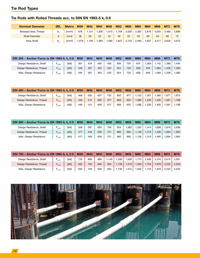
Tie Rods with Rolled Threads acc. to DIN EN 1993-5 kt 0.9
Nominal Diameter ØD1 Metric M39 M42 M45 M48 M52 M56 M60 M64 M68 M72 M76
Stressed Area, Thread As [mm²] 976 1,121 1,306 1,473 1,758 2,030 2,362 2,676 3,055 3,460 3,889
Shaft Diameter d [mm] 36 39 42 45 49 52 56 60 64 68 72
Area, Shaft Ag [mm²] 1,018 1,195 1,385 1,590 1,847 2,124 2,463 2,827 3,217 3,632 4,072
DSI 355 – Anchor Force to EN 1993-5, kt 0.9 M39 M42 M45 M48 M52 M56 M60 M64 M68 M72 M76
Design Resistance, Shaft Fg,Rd [kN] 361 424 492 565 656 754 874 1,004 1,142 1,289 1,445
Design Resistance, Thread Ft,Rd [kN] 346 397 463 522 624 720 838 949 1,084 1,228 1,380
Max� Design Resistance Fu,Rd [kN] 346 397 463 522 624 720 838 949 1,084 1,228 1,380
DSI 460 – Anchor Force to EN 1993-5, kt 0.9 M39 M42 M45 M48 M52 M56 M60 M64 M68 M72 M76
Design Resistance, Shaft Fg,Rd [kN] 468 550 637 732 850 977 1,133 1,301 1,480 1,671 1,873
Design Resistance, Thread Ft,Rd [kN] 448 515 600 677 808 933 1,086 1,230 1,405 1,591 1,788
Max� Design Resistance Fu,Rd [kN] 448 515 600 677 808 933 1,086 1,230 1,405 1,591 1,788
DSI 500 – Anchor Force to EN 1993-5, kt 0.9 M39 M42 M45 M48 M52 M56 M60 M64 M68 M72 M76
Design Resistance, Shaft Fg,Rd [kN] 509 597 693 795 924 1,062 1,232 1,414 1,608 1,816 2,036
Design Resistance, Thread Ft,Rd [kN] 477 548 639 721 860 993 1,156 1,310 1,495 1,694 1,904
Max� Design Resistance Fu,Rd [kN] 477 548 639 721 860 993 1,156 1,310 1,495 1,694 1,904
DSI 720 – Anchor Force to EN 1993-5, kt 0.9 M39 M42 M45 M48 M52 M56 M60 M64 M68 M72 M76
Design Resistance, Shaft Fg,Rd [kN] 733 860 998 1,145 1,330 1,529 1,773 2,036 2,316 2,615 2,931
Design Resistance, Thread Ft,Rd [kN] 632 726 846 954 1,139 1,315 1,530 1,734 1,979 2,242 2,520
Max� Design Resistance Fu,Rd [kN] 632 726 846 954 1,139 1,315 1,530 1,734 1,979 2,242 2,520
14

M80 M85 M90 M95 M100 M105 M110 M115 M120 M125 M130 M135 M140 M145 M150 M155 M160
4,344 4,948 5,591 6,273 6,995 7,755 8,556 9,395 10,274 11,191 12,149 13,145 14,181 15,256 16,370 17,524 18,716
76 81 86 91 96 101 106 111 116 121 126 131 136 141 146 151 156
4,536 5,153 5,809 6,504 7,238 8,012 8,825 9,677 10,568 11,499 12,469 13,478 14,527 15,615 16,742 17,908 19,113
M80 M85 M90 M95 M100 M105 M110 M115 M120 M125 M130 M135 M140 M145 M150 M155 M160
1,610 1,829 2,062 2,309 2,570 2,844 3,133 3,435 3,752 4,082 4,426 4,785 5,157 5,543 5,943 6,357 6,785
1,542 1,756 1,984 2,226 2,483 2,753 3,037 3,335 3,647 3,972 4,312 4,666 5,034 5,415 5,811 6,220 6,644
1,542 1,756 1,984 2,226 2,483 2,753 3,037 3,335 3,647 3,972 4,312 4,666 5,034 5,415 5,811 6,220 6,644
M80 M85 M90 M95 M100 M105 M110 M115 M120 M125 M130 M135 M140 M145 M150 M155 M160
2,087 2,370 2,672 2,992 3,330 3,685 4,059 4,451 4,861 5,290 5,736 6,200 6,682 7,183 7,701 8,238 8,792
1,998 2,276 2,571 2,885 3,217 3,567 3,935 4,321 4,726 5,147 5,588 6,046 6,523 7,017 7,530 8,060 8,609
1,998 2,276 2,571 2,885 3,217 3,567 3,935 4,321 4,726 5,147 5,588 6,046 6,523 7,017 7,530 8,060 8,609
M80 M85 M90 M95 M100 M105 M110 M115 M120 M125 M130 M135 M140 M145 M150 M155 M160
2,268 2,576 2,904 3,252 3,619 4,006 4,412 4,838 5,284 5,750 6,234 6,739 7,263 7,807 8,371 8,954 9,557
2,126 2,422 2,737 3,071 3,424 3,797 4,189 4,599 5,030 5,479 5,948 6,435 6,943 7,469 8,014 8,579 9,163
2,126 2,422 2,737 3,071 3,424 3,797 4,189 4,599 5,030 5,479 5,948 6,435 6,943 7,469 8,014 8,579 9,163
M80 M85 M90 M95 M100 M105 M110 M115 M120 M125 M130 M135 M140 M145 M150 M155 M160
3,266 3,710 4,182 4,683 5,212 5,769 6,354 6,967 7,609 8,279 8,978 9,704 10,459 11,242 12,054 12,894 13,762
2,814 3,206 3,622 4,064 4,532 5,025 5,544 6,087 6,657 7,251 7,872 8,517 9,189 9,885 10,607 11,355 12,128
2,814 3,206 3,622 4,064 4,532 5,025 5,544 6,087 6,657 7,251 7,872 8,517 9,189 9,885 10,607 11,355 12,128
l=variable ≥ 1,000 l=variable ≥ 1,000
15
Tie Rod Types
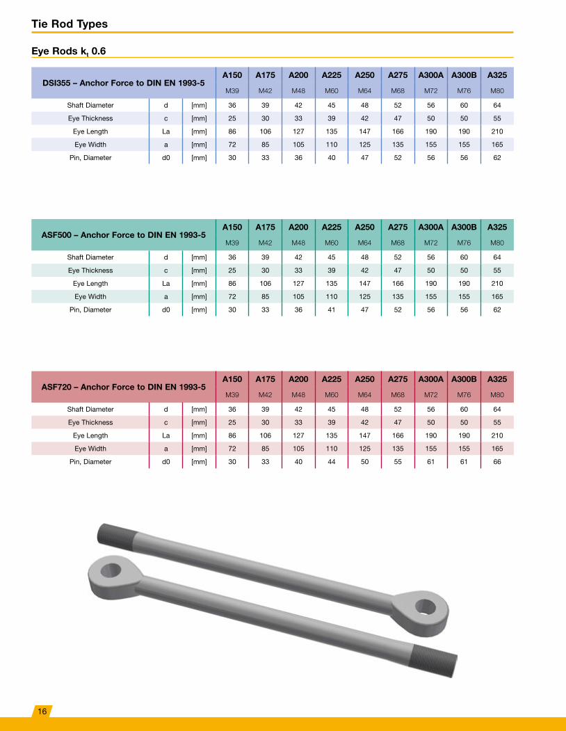
Eye Rods kt 0.6
DSI355 – Anchor Force to DIN EN 1993-5A150 A175 A200 A225 A250 A275 A300A A300B A325
M39 M42 M48 M60 M64 M68 M72 M76 M80
Shaft Diameter d [mm] 36 39 42 45 48 52 56 60 64
Eye Thickness c [mm] 25 30 33 39 42 47 50 50 55
Eye Length La [mm] 86 106 127 135 147 166 190 190 210
Eye Width a [mm] 72 85 105 110 125 135 155 155 165
Pin, Diameter d0 [mm] 30 33 36 40 47 52 56 56 62
ASF500 – Anchor Force to DIN EN 1993-5A150 A175 A200 A225 A250 A275 A300A A300B A325
M39 M42 M48 M60 M64 M68 M72 M76 M80
Shaft Diameter d [mm] 36 39 42 45 48 52 56 60 64
Eye Thickness c [mm] 25 30 33 39 42 47 50 50 55
Eye Length La [mm] 86 106 127 135 147 166 190 190 210
Eye Width a [mm] 72 85 105 110 125 135 155 155 165
Pin, Diameter d0 [mm] 30 33 36 41 47 52 56 56 62
ASF720 – Anchor Force to DIN EN 1993-5A150 A175 A200 A225 A250 A275 A300A A300B A325
M39 M42 M48 M60 M64 M68 M72 M76 M80
Shaft Diameter d [mm] 36 39 42 45 48 52 56 60 64
Eye Thickness c [mm] 25 30 33 39 42 47 50 50 55
Eye Length La [mm] 86 106 127 135 147 166 190 190 210
Eye Width a [mm] 72 85 105 110 125 135 155 155 165
Pin, Diameter d0 [mm] 30 33 40 44 50 55 61 61 66
16

A350 A375A A375B A400 A425 A450 A475 A500 A525 A550 A575 A600 A625 A650
M85 M90 M95 M100 M105 M115 M120 M125 M130 M135 M145 M150 M155 M160
68 72 75 80 85 90 95 100 105 110 115 120 125 130
60 63 63 66 72 75 80 85 90 95 100 105 115 120
220 235 235 253 290 300 323 340 350 365 373 380 439 459
180 190 190 210 230 240 255 270 275 290 300 310 330 340
68 70 70 76 80 85 90 95 100 100 105 110 115 120
A350 A375A A375B A400 A425 A450 A475 A500 A525 A550 A575 A600 A625 A650
M85 M90 M95 M100 M105 M115 M120 M125 M130 M135 M145 M150 M155 M160
68 72 75 80 85 90 95 100 105 110 115 120 125 130
60 63 63 66 72 75 80 85 90 95 100 105 115 120
220 235 235 253 290 300 323 340 350 365 373 380 439 459
180 190 190 210 230 240 255 270 275 290 300 310 330 340
68 70 70 76 80 85 90 95 100 105 110 115 120 125
A350 A375A A375B A400 A425 A450 A475 A500 A525 A550 A575 A600 A625 A650
M85 M90 M95 M100 M105 M115 M120 M125 M130 M135 M145 M150 M155 M160
68 72 75 80 85 90 95 100 105 110 115 120 125 130
60 63 63 66 72 75 80 85 90 95 100 105 115 120
220 235 235 253 290 300 323 340 350 365 373 380 439 459
180 190 190 210 230 240 255 270 275 290 300 310 330 340
72 76 76 85 90 95 100 105 110 110 115 125 130 135
17
Tie Rod Connection Elements
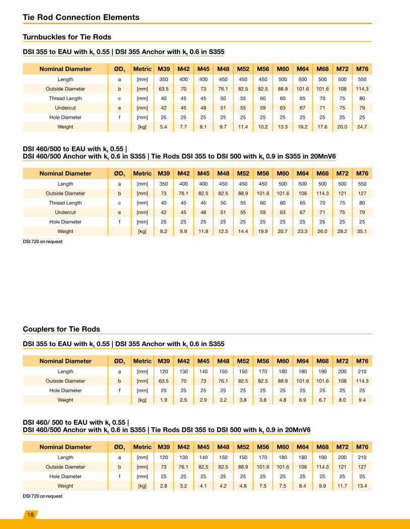
Turnbuckles for Tie Rods
DSI 355 to EAU with kt 0.55 | DSI 355 Anchor with kt 0.6 in S355
Nominal Diameter ØD1 Metric M39 M42 M45 M48 M52 M56 M60 M64 M68 M72 M76
Length a [mm] 350 400 400 450 450 450 500 500 500 500 550
Outside Diameter b [mm] 63�5 70 73 76�1 82�5 82�5 88�9 101�6 101�6 108 114�3
Thread Length c [mm] 40 45 45 50 55 60 60 65 70 75 80
Undercut e [mm] 42 45 48 51 55 59 63 67 71 75 79
Hole Diameter f [mm] 25 25 25 25 25 25 25 25 25 25 25
Weight [kg] 5�4 7�7 8�1 9�7 11�4 10�2 13�3 19�2 17�6 20�0 24�7
Couplers for Tie Rods
DSI 355 to EAU with kt 0.55 | DSI 355 Anchor with kt 0.6 in S355
Nominal Diameter ØD1 Metric M39 M42 M45 M48 M52 M56 M60 M64 M68 M72 M76
Length a [mm] 120 130 140 150 150 170 180 180 190 200 210
Outside Diameter b [mm] 63�5 70 73 76�1 82�5 82�5 88�9 101�6 101�6 108 114�3
Hole Diameter f [mm] 25 25 25 25 25 25 25 25 25 25 25
Weight [kg] 1�9 2�5 2�9 3�2 3�8 3�8 4�8 6�9 6�7 8�0 9�4
DSI 460/500 to EAU with kt 0.55 | DSI 460/500 Anchor with kt 0.6 in S355 | Tie Rods DSI 355 to DSI 500 with kt 0.9 in S355 in 20MnV6
Nominal Diameter ØD1 Metric M39 M42 M45 M48 M52 M56 M60 M64 M68 M72 M76
Length a [mm] 350 400 400 450 450 450 500 500 500 500 550
Outside Diameter b [mm] 73 76�1 82�5 82�5 88�9 101�6 101�6 108 114�3 121 127
Thread Length c [mm] 40 45 45 50 55 60 60 65 70 75 80
Undercut e [mm] 42 45 48 51 55 59 63 67 71 75 79
Hole Diameter f [mm] 25 25 25 25 25 25 25 25 25 25 25
Weight [kg] 8�2 9�9 11�8 12�5 14�4 19�9 20�7 23�3 26�0 29�2 35�1
DSI 720 on request
DSI 460/ 500 to EAU with kt 0.55 | DSI 460/500 Anchor with kt 0.6 in S355 | Tie Rods DSI 355 to DSI 500 with kt 0.9 in 20MnV6
Nominal Diameter ØD1 Metric M39 M42 M45 M48 M52 M56 M60 M64 M68 M72 M76
Length a [mm] 120 130 140 150 150 170 180 180 190 200 210
Outside Diameter b [mm] 73 76�1 82�5 82�5 88�9 101�6 101�6 108 114�3 121 127
Hole Diameter f [mm] 25 25 25 25 25 25 25 25 25 25 25
Weight [kg] 2�8 3�2 4�1 4�2 4�8 7�5 7�5 8�4 9�9 11�7 13�4
DSI 720 on request
18

M80 M85 M90 M95 M100 M105 M110 M115 M120 M125 M130 M135 M140 M145 M150 M155 M160
550 550 550 550 550 550 550 550 550 550 550 550 550 550 550 550 550
114�3 121 127 133 139�7 152�4 152�4 159 165�1 177�8 177�8 191 193�7 203 216 216 219�1
80 85 90 95 100 105 110 115 120 125 130 135 140 145 150 155 160
83 88 93 98 103 108 113 118 123 128 133 138 143 148 153 158 163
25 25 25 25 25 25 25 25 25 25 25 25 25 25 25 25 25
22�6 25�1 27�2 29�4 32�3 41�4 37�7 40�9 43�6 54�2 49�9 61�9 60�8 68�4 81�9 76�7 76�0
M80 M85 M90 M95 M100 M105 M110 M115 M120 M125 M130 M135 M140 M145 M150 M155 M160
550 550 550 550 550 550 550 550 550 550 550 550 550 550 550 550 550
133 139�7 141�3 152�4 159 168�3 177�8 191 193�7 203 203 219�1 219�1 229 229 244�5 244�5
80 85 90 95 100 105 110 115 120 125 130 135 140 145 150 155 160
83 88 93 98 103 108 113 118 123 128 133 138 143 148 153 158 163
25 25 25 25 25 25 25 25 25 25 25 25 25 25 25 25 25
38�3 41�7 40�2 48�2 51�8 58�7 66�2 78�9 78�4 86�8 82�4 101�0 96�3 106�5 101�5 121�2 115�9
M80 M85 M90 M95 M100 M105 M110 M115 M120 M125 M130 M135 M140 M145 M150 M155 M160
225 240 250 260 260 260 260 260 260 260 260 270 280 290 300 310 320
114�3 121 127 133 139�7 152�4 152�4 159 165�1 177�8 177�8 191 193�7 203 216 216 219�1
25 25 25 25 25 25 25 25 25 25 25 25 25 25 25 25 25
9�2 11�0 12�4 13�9 15�3 19�6 17�8 19�3 20�6 25�6 23�6 30�4 30�9 36�1 44�7 43�3 44�2
M80 M85 M90 M95 M100 M105 M110 M115 M120 M125 M130 M135 M140 M145 M150 M155 M160
225 240 250 260 275 285 295 305 320 330 340 350 360 370 380 390 400
133 139�7 141�3 152�4 159 168�3 177�8 191 193�7 203 203 219�1 219�1 229 229 244�5 244�5
25 25 25 25 25 25 25 25 25 25 25 25 25 25 25 25 25
15�7 18�2 18�3 22�8 25�9 30�4 35�5 43�7 45�6 52�1 51�0 64�3 63�0 71�7 70�1 86�0 84�3
a
c
b
f
e
c
D
b
a
f
D
19
Tie Rod Connection Elements
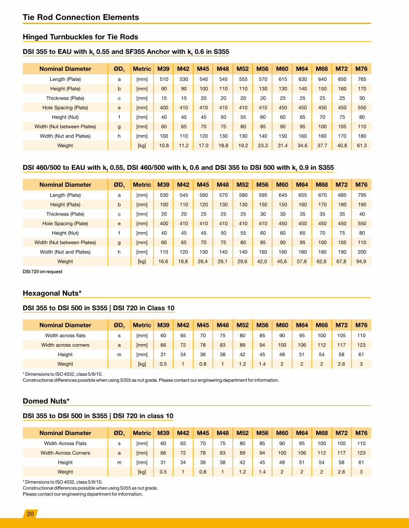
Hinged Turnbuckles for Tie Rods
DSI 355 to EAU with kt 0.55 and SF355 Anchor with kt 0.6 in S355
Nominal Diameter ØD1 Metric M39 M42 M45 M48 M52 M56 M60 M64 M68 M72 M76
Length (Plate) a [mm] 510 530 540 545 555 570 615 630 640 650 765
Height (Plate) b [mm] 90 90 100 110 110 130 130 140 150 160 170
Thickness (Plate) c [mm] 15 15 20 20 20 20 25 25 25 25 30
Hole Spacing (Plate) e [mm] 400 410 410 410 410 410 450 450 450 450 550
Height (Nut) f [mm] 40 45 45 50 55 60 60 65 70 75 80
Width (Nut between Plates) g [mm] 60 65 70 75 80 85 90 95 100 105 110
Width (Nut and Plates) h [mm] 100 110 120 130 130 140 150 160 160 170 180
Weight [kg] 10�8 11�2 17�0 18�8 19�2 23�3 31�4 34�6 37�7 40�8 61�3
DSI 460/500 to EAU with kt 0.55, DSI 460/500 with kt 0.6 and DSI 355 to DSI 500 with kt 0.9 in S355
Nominal Diameter ØD1 Metric M39 M42 M45 M48 M52 M56 M60 M64 M68 M72 M76
Length (Plate) a [mm] 530 545 560 570 580 595 645 655 670 685 795
Height (Plate) b [mm] 100 110 120 130 130 150 150 160 170 180 190
Thickness (Plate) c [mm] 20 20 25 25 25 30 30 35 35 35 40
Hole Spacing (Plate) e [mm] 400 410 410 410 410 410 450 450 450 450 550
Height (Nut) f [mm] 40 45 45 50 55 60 60 65 70 75 80
Width (Nut between Plates) g [mm] 60 65 70 75 80 85 90 95 100 105 110
Width (Nut and Plates) h [mm] 110 120 130 140 140 160 160 180 180 190 200
Weight [kg] 16�6 18,8 26,4 29,1 29,6 42,0 45,6 57,6 62,6 67,8 94,9
DSI 720 on request
Hexagonal Nuts*
DSI 355 to DSI 500 in S355 | DSI 720 in Class 10
Nominal Diameter ØD1 Metric M39 M42 M45 M48 M52 M56 M60 M64 M68 M72 M76
Width across flats s [mm] 60 65 70 75 80 85 90 95 100 105 110
Width across corners a [mm] 66 72 78 83 89 94 100 106 112 117 123
Height m [mm] 31 34 36 38 42 45 48 51 54 58 61
Weight [kg] 0�5 1 0�8 1 1�2 1�4 2 2 2 2�6 3
* Dimensions to ISO 4032, class 5/8/10� Constructional differences possible when using S355 as nut grade� Please contact our engineering department for information�
Domed Nuts*
DSI 355 to DSI 500 in S355 | DSI 720 in class 10
Nominal Diameter ØD1 Metric M39 M42 M45 M48 M52 M56 M60 M64 M68 M72 M76
Width Across Flats s [mm] 60 65 70 75 80 85 90 95 100 105 110
Width Across Corners a [mm] 66 72 78 83 89 94 100 106 112 117 123
Height m [mm] 31 34 36 38 42 45 48 51 54 58 61
Weight [kg] 0�5 1 0�8 1 1�2 1�4 2 2 2 2�6 3
* Dimensions to ISO 4032, class 5/8/10� Constructional differences possible when using S355 as nut grade� Please contact our engineering department for information�
20

M80 M85 M90 M95 M100 M105 M110 M115 M120 M125 M130 M135 M140 M145 M150 M155 M160
775 790 840 860 865 875 880 880 900 900 915 935 945 960 975 990 1,005
180 190 200 210 220 230 240 250 270 280 290 300 310 320 330 350 360
30 30 35 35 40 40 40 40 45 45 50 50 50 55 55 60 60
550 550 590 590 580 580 570 560 560 550 550 550 550 550 550 550 550
80 85 90 95 100 105 110 115 120 125 130 135 140 145 150 155 160
115 120 130 135 145 150 155 165 170 180 185 190 200 210 210 220 230
190 190 210 220 240 240 250 260 270 280 300 300 310 330 330 350 360
65�7 70�7 92�3 99�2 119�5 126�4 132�6 138�2 171�7 178�0 208�3 220�2 230�0 265�3 277�8 326�4 340�8
M80 M85 M90 M95 M100 M105 M110 M115 M120 M125 M130 M135 M140 M145 M150 M155 M160
810 860 880 900 910 925 930 935 955 960 980 995 1,010 1,025 1,045 1,060 1,080
200 240 230 240 260 270 280 290 310 320 340 350 360 370 390 400 420
40 45 45 50 55 55 60 60 65 65 70 70 75 75 80 80 85
550 550 590 590 580 580 570 560 560 550 550 550 550 550 550 550 550
80 85 90 95 100 105 110 115 120 125 130 135 140 145 150 155 160
115 120 130 135 145 150 155 165 170 180 185 190 200 210 210 220 230
210 220 230 250 270 270 290 300 310 320 340 340 360 370 380 390 410
101�7 145�8 143�0 169�6 204�3 215�7 245�3 255�4 302�1 313�5 366�2 382�7 428�1 446�6 511�9 532�5 605�3
hgc
c
ae
b
f
g D
M80 M85 M90 M95 M100 M105 M110 M115 M120 M125 M130 M135 M140 M145 M150 M155 M160
115 120 130 135 145 150 155 165 170 180 185 190 200 210 210 220 230
128 134 145 151 162 168 173 185 190 202 207 212 224 235 235 245 255
64 68 72 76 80 84 88 92 96 100 104 108 112 116 120 124 128
3�4 3�9 4�9 5�6 6�8 7�5 8�2 10�1 11�7 13 13�8 15�2 17�5 20�7 20 23�1 26�5
a
sh
D
M80 M85 M90 M95 M100 M105 M110 M115 M120 M125 M130 M135 M140 M145 M150 M155 M160
115 120 130 135 145 150 155 165 170 180 185 190 200 210 210 220 230
128 134 145 151 162 168 173 185 190 202 207 212 224 235 235 245 255
64 68 72 76 80 84 88 92 96 100 104 108 112 116 120 124 128
3�4 3�9 4�9 5�6 6�8 8 8�2 10�1 11�7 13 13�8 15�2 17�5 20�7 20 23 27
s
a
h
r
21

Tie Rod Connection Elements
Shackle Joint for Tie Rods
DSI 355
Nominal Diameter ØD1 Metric A150 A175 A200 A225 A250 A275 A300A A300B A325
Length (Plate) a [mm] 195 220 255 270 310 340 380 380 405
Height (Plate) b [mm] 80 90 100 110 130 140 150 150 160
Thickness (Plate) c [mm] 15 15 20 20 25 25 25 30 30
Hole Spacing (Plate) e [mm] 90 105 130 135 150 165 190 190 200
Diameter (Pin) g [mm] 30 33 36 40 47 52 56 56 62
Length (Pin) k [mm] 90 95 110 120 135 140 145 160 160
Weight [kg] 4�3 5�5 9�1 10�8 18 21�6 25�9 30�5 35�1
DSI 500
Nominal Diameter ØD1 Metric A150 A175 A200 A225 A250 A275 A300A A300B A325
Length (Plate) a [mm] 195 220 255 275 310 340 380 380 405
Height (Plate) b [mm] 80 90 100 110 130 140 150 150 160
Thickness (Plate) c [mm] 15 20 20 25 25 30 30 35 35
Hole Spacing (Plate) e [mm] 90 105 130 135 150 165 190 190 200
Diameter (Pin) g [mm] 30 33 36 41 47 52 56 56 62
Length (Pin) k [mm] 90 105 110 130 135 150 155 170 170
Weight [kg] 4�3 7 9�1 13�4 18 25�3 30�4 35 40�1
DSI 720 on request
Rocker Plate for Tie Rods
DSI 355 to EAU with kt 0.55 and DSI 355 Anchor with kt 0.6 in S355
Nominal Diameter ØD1 Metric M39 M42 M45 M48 M52 M56 M60 M64 M68 M72 M76
Plate Width b [mm] 80 90 90 100 100 110 120 120 130 140 140
Plate Height h [mm] 70 80 80 90 90 100 110 110 120 120 130
Plate Thickness t [mm] 20 30 30 30 30 30 40 40 40 40 40
Rocker s [mm] 50 50 50 50 50 50 50 50 50 50 50
Weight [kg] 1�1 1�8 1�8 2�2 2 2�5 3�8 3�7 4�4 4�5 4�9
Threaded Rocker Plate for Tie Rods
DSI 355 to EAU with kt 0.55 and DSI 355 Anchor with kt 0.6 in S355
Nominal Diameter ØD1 Metric M39 M42 M45 M48 M52 M56 M60 M64 M68 M72 M76
Plate Width b [mm] 100 110 110 120 130 150 150 150 160 160 180
Plate Height h [mm] 100 110 110 120 130 150 150 150 160 160 180
Plate Thickness t [mm] 35 40 40 45 45 50 55 60 65 65 70
Rocker s [mm] 50 50 50 50 50 50 50 50 50 50 50
Weight [kg] 2�9 3�9 3�8 5 5�8 8�6 9�2 9�7 11�9 11�7 16�1
22

A350 A375A A375B A400 A425 A450 A475 A500 A525 A550 A575 A600 A625 A650
445 465 465 505 545 570 605 640 660 680 705 735 775 805
180 180 180 200 210 220 230 250 260 260 270 280 300 310
30 35 35 40 40 40 45 50 50 50 55 55 60 60
220 230 230 255 280 290 310 325 330 350 360 375 400 410
68 70 70 76 80 85 90 95 100 100 105 110 115 120
165 180 185 200 205 215 230 245 250 255 275 280 295 300
43�5 52�4 52�7 71�7 81�4 90�4 111�9 141�3 152�7 157�4 186�2 202�5 246�9 266�3
A350 A375A A375B A400 A425 A450 A475 A500 A525 A550 A575 A600 A625 A650
445 465 465 505 545 570 605 640 660 695 720 750 795 820
180 180 180 200 210 220 230 250 260 270 280 300 310 320
40 40 40 45 50 50 55 55 60 60 65 65 70 70
220 230 230 255 280 290 310 325 330 350 360 375 400 410
68 70 70 76 80 85 90 95 100 105 110 115 120 125
185 190 195 210 225 235 250 255 270 275 295 300 315 320
56 58�9 59�2 79�6 99�3 110 133�6 153�8 179�5 197�2 229�6 256�6 301�1 322�2
M80 M85 M90 M95 M100 M105 M110 M115 M120 M125 M130 M135 M140 M145 M150 M155 M160
150 160 180 180 190 200 210 220 230 240 250 260 270 280 290 300 310
130 140 150 150 160 170 180 190 190 200 210 220 230 240 240 250 250
40 50 50 50 50 60 60 60 60 70 70 70 70 80 80 90 90
60 60 60 60 60 60 60 60 60 60 60 60 60 60 60 60 60
5�4 7�8 9�6 9�2 10�3 14 15�5 17�1 17�2 21�7 23�7 25�8 28�6 34�4 35�3 42�5 43�5
M80 M85 M90 M95 M100 M105 M110 M115 M120 M125 M130 M135 M140 M145 M150 M155 M160
180 180 200 200 220 220 220 230 240 250 260 280 280 300 300 320 320
180 180 200 200 220 220 220 230 240 250 260 280 280 300 300 320 320
80 80 85 95 100 105 110 115 120 130 140 150 150 150 150 160 160
60 60 60 60 60 60 60 60 60 60 60 60 60 60 60 60 60
18�3 17�8 23�7 25�7 33�2 34 34�8 39�7 44�9 52�6 61�1 77�1 75�7 88�3 86�8 106�7 105�1
d
e
a
g
b
h
b
S dp
h
b
D
20
50
23

Tie Rod Connection Elements
Universal Joints for Tie Rods
DSI 355 to EAU with kt 0.55 and DSI 355 Anchor with kt 0.6 in S355
Nominal Diameter ØD1 Metric M39 M42 M45 M48 M52 M56 M60 M64 M68 M72 M76
Length (Plate) a [mm] 195 220 235 265 275 290 305 330 350 365 405
Height and Width (Plate) b [mm] 90 90 100 110 110 130 130 140 150 160 170
Leg Thickness (Plate) c [mm] 14 15 16 17 18 20 21 23 24 25 27
Hole Spacing (Plate) e [mm] 105 120 125 150 150 155 160 175 190 190 220
Leg Length (Plate) f [mm] 91 103 110 124 129 135 142 154 163 170 189
Diameter (Pin) g [mm] 33 35 39 41 43 48 50 55 58 61 65
Length (Pin) k [mm] 90 95 100 105 110 120 125 130 140 145 150
Weight [kg] 5�2 6�2 7�9 10�3 11�3 15�9 17�5 22 26�4 30�7 38�3
Universal Joints at Waling for Tie Rods
DSI 355 to EAU with kt 0.55 and DSI 355 Anchor with kt 0.6 in S355
Nominal Diameter ØD1 Metric M39 M42 M45 M48 M52 M56 M60 M64 M68 M72 M76
Length (Plate) a [mm] Length to suit installation conditions
Height and Width (Plate) b [mm] 90 90 100 110 110 130 130 140 150 160 170
Leg Thickness (Plate) c [mm] 14 15 16 17 18 20 21 23 24 25 27
Hole Spacing (Plate) e [mm] Length to suit installation conditions
Leg Length (Plate) f [mm] 91 103 110 124 129 135 142 154 163 170 189
Diameter (Pin) g [mm] 33 35 39 41 43 48 50 55 58 61 65
Length (Pin) k [mm] 90 95 100 105 110 120 125 130 140 145 150
DSI 720 on request� Length (a) and hole spacing (e) for a universal joint at the waling to suit customer specification or type of installation�
24

M80 M85 M90 M95 M100 M105 M110 M115 M120 M125 M130 M135 M140 M145 M150 M155 M160
425 435 475 500 545 580 595 615 655 680 705 740 755 785 815 860 890
180 190 200 210 220 230 240 250 270 280 290 300 310 320 330 350 360
28 30 32 34 36 37 39 40 42 44 46 48 50 52 55 57 58
230 230 255 265 295 320 320 330 355 365 380 400 400 415 430 460 470
199 203 222 233 255 272 278 288 307 318 330 346 353 367 380 402 416
68 73 77 82 87 91 95 99 104 108 113 118 122 126 131 136 141
160 165 175 185 195 200 210 215 225 235 245 255 260 270 280 290 300
44�2 51�3 62�3 73�6 88 100�3 113�8 125�7 151�4 171 191�8 217�4 237�8 264�9 299�2 345�4 376�5
M80 M85 M90 M95 M100 M105 M110 M115 M120 M125 M130 M135 M140 M145 M150 M155 M160
Length to suit installation conditions
180 190 200 210 220 230 240 250 270 280 290 300 310 320 330 350 360
28 30 32 34 36 37 39 40 42 44 46 48 50 52 55 57 58
Length to suit installation conditions
199 203 222 233 255 272 278 288 307 318 330 346 353 367 380 402 416
68 73 77 82 87 91 95 99 104 108 113 118 122 126 131 136 141
160 165 175 185 195 200 210 215 225 235 245 255 260 270 280 290 300
g
b d
e
a
f
c
25

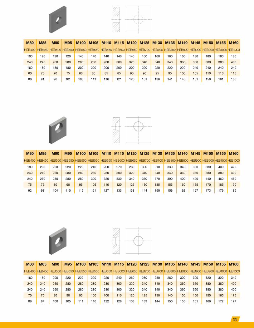
Tie Rod and Waling Joints
Rear Plate for DSI 355 Tie Rods acc. to 1993-5 with kt 0.9 in S355
Type I Standard – Angle 0°
Nominal Diameter ØD1 Metric M39 M42 M45 M48 M52 M56 M60 M64 M68 M72 M76
Gurtung UNP180 UNP200 UNP200 UNP220 UNP240 UNP240 UNP260 UNP280 UNP300 UNP320 UNP320
Waling Spacing 80 80 80 80 80 80 100 100 100 100 100
Width wp [mm] 160 160 180 180 180 200 200 200 220 220 240
Height hp [mm] 140 140 140 140 140 140 160 160 160 160 160
Thickness tp [mm] 20 25 25 25 25 30 30 30 30 30 30
Hole Diameter Ød [mm] 45 48 51 54 58 62 66 70 74 78 82
Type II Conical/Off-Centered – Angle up to max. 10°
Nominal Diameter ØD1 Metric M39 M42 M45 M48 M52 M56 M60 M64 M68 M72 M76
Gurtung UNP180 UNP200 UNP200 UNP220 UNP240 UNP240 UNP260 UNP280 UNP300 UNP320 UNP320
Waling Spacing 100 100 120 120 120 140 140 160 160 180 180
Width wp [mm] 160 160 180 180 180 200 200 200 220 220 240
Height hp [mm] 160 160 180 180 180 200 200 220 220 240 240
Thickness tp [mm] 20 25 25 25 25 30 35 40 40 45 45
Hole Diameter Ød [mm] 48 51 55 59 64 68 73 78 83 88 93
Type III Conical/Centered – Angle up to max. 5°
Nominal Diameter ØD1 Metric M39 M42 M45 M48 M52 M56 M60 M64 M68 M72 M76
Gurtung UNP180 UNP200 UNP200 UNP220 UNP240 UNP240 UNP260 UNP280 UNP300 UNP320 UNP320
Waling Spacing 100 100 120 120 120 140 140 140 160 160 180
Width wp [mm] 160 160 180 180 180 200 200 200 220 220 240
Height hp [mm] 160 160 180 180 180 200 200 200 220 220 240
Thickness tp [mm] 20 20 25 25 25 30 35 35 40 40 45
Hole Diameter Ød [mm] 45 48 51 54 58 62 67 71 76 80 84
26

M80 M85 M90 M95 M100 M105 M110 M115 M120 M125 M130 M135 M140 M145 M150 M155 M160
UNP350 UNP380 UNP400 UNP400 HEB340 HEB360 HEB400 HEB450 HEB450 HEB500 HEB550 HEB550 HEB600 HEB600 HEB650 HEB650 HEB700
100 120 120 120 140 140 140 140 140 160 160 160 160 180 180 180 180
240 240 260 280 280 280 280 300 320 340 340 340 360 360 380 380 400
160 180 180 180 200 200 200 200 200 220 220 220 220 240 240 240 240
35 40 40 45 45 45 45 45 50 50 55 55 55 60 60 65 65
86 91 96 101 106 111 116 121 126 131 136 141 146 151 156 161 166
M80 M85 M90 M95 M100 M105 M110 M115 M120 M125 M130 M135 M140 M145 M150 M155 M160
UNP350 UNP380 UNP400 UNP400 HEB340 HEB360 HEB400 HEB450 HEB450 HEB500 HEB550 HEB550 HEB600 HEB600 HEB650 HEB650 HEB700
180 200 220 220 220 240 260 270 280 300 310 330 340 360 380 400 420
240 240 260 280 280 280 280 300 320 340 340 340 360 360 380 380 400
240 260 280 280 280 300 320 330 340 360 370 390 400 420 440 460 480
45 55 55 55 60 70 70 75 80 85 90 100 105 105 110 120 125
98 104 110 116 122 128 134 140 146 152 158 164 170 176 182 188 195
M80 M85 M90 M95 M100 M105 M110 M115 M120 M125 M130 M135 M140 M145 M150 M155 M160
UNP350 UNP380 UNP400 UNP400 HEB340 HEB360 HEB400 HEB450 HEB450 HEB500 HEB550 HEB550 HEB600 HEB600 HEB650 HEB650 HEB700
180 180 200 220 220 220 220 240 260 280 280 280 300 300 320 320 340
240 240 260 280 280 280 280 300 320 340 340 340 360 360 380 380 400
240 240 260 280 280 280 280 300 320 340 340 340 360 360 380 380 400
45 50 50 55 60 65 65 70 75 80 85 90 95 95 100 105 110
89 94 100 105 111 116 122 128 133 139 144 150 155 161 166 172 177
27
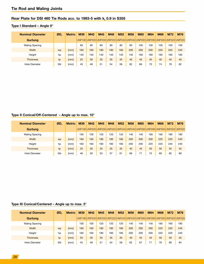
Tie Rod and Waling Joints
Rear Plate for DSI 460 Tie Rods acc. to 1993-5 with kt 0.9 in S355
Type I Standard – Angle 0°
Nominal Diameter ØD1 Metric M39 M42 M45 M48 M52 M56 M60 M64 M68 M72 M76
Gurtung UNP180 UNP200 UNP200 UNP220 UNP240 UNP240 UNP260 UNP280 UNP300 UNP320 UNP320
Waling Spacing 80 80 80 80 80 80 100 100 100 100 100
Width wp [mm] 160 160 180 180 180 200 200 200 220 220 240
Height hp [mm] 140 140 140 140 140 140 160 160 160 160 160
Thickness tp [mm] 25 30 35 35 35 40 40 40 40 40 40
Hole Diameter Ød [mm] 45 48 51 54 58 62 66 70 74 78 82
Type II Conical/Off-Centered – Angle up to max. 10°
Nominal Diameter ØD1 Metric M39 M42 M45 M48 M52 M56 M60 M64 M68 M72 M76
Gurtung UNP180 UNP200 UNP200 UNP220 UNP240 UNP240 UNP260 UNP280 UNP300 UNP320 UNP320
Waling Spacing 100 100 120 120 120 140 140 160 160 180 180
Width wp [mm] 160 160 180 180 180 200 200 200 220 220 240
Height hp [mm] 160 160 180 180 180 200 200 220 220 240 240
Thickness tp [mm] 25 30 35 35 35 40 45 50 50 55 55
Hole Diameter Ød [mm] 46 50 53 57 61 66 71 75 80 85 89
Type III Conical/Centered – Angle up to max. 5°
Nominal Diameter ØD1 Metric M39 M42 M45 M48 M52 M56 M60 M64 M68 M72 M76
Gurtung UNP180 UNP200 UNP200 UNP220 UNP240 UNP240 UNP260 UNP280 UNP300 UNP320 UNP320
Waling Spacing 100 100 120 120 120 140 140 140 160 160 180
Width wp [mm] 160 160 180 180 180 200 200 200 220 220 240
Height hp [mm] 160 160 180 180 180 200 200 200 220 220 240
Thickness tp [mm] 25 30 35 35 35 40 45 45 50 50 55
Hole Diameter Ød [mm] 45 48 51 54 58 62 67 71 76 80 84
28
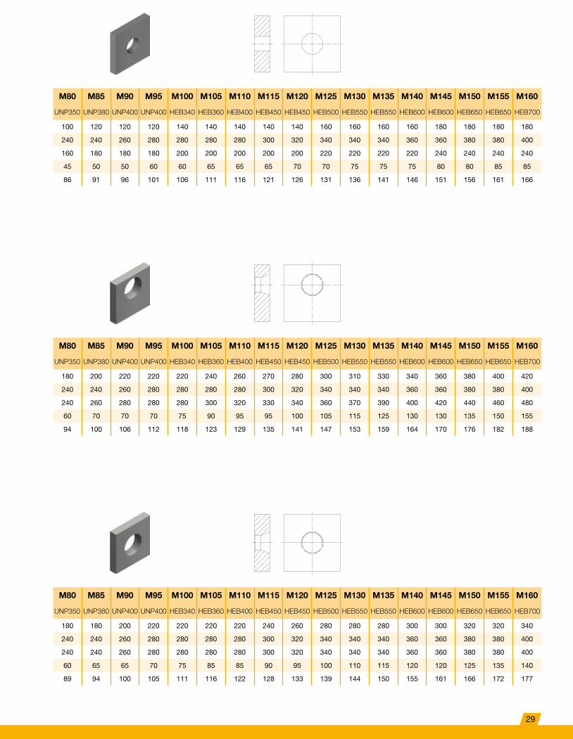
M80 M85 M90 M95 M100 M105 M110 M115 M120 M125 M130 M135 M140 M145 M150 M155 M160
UNP350 UNP380 UNP400 UNP400 HEB340 HEB360 HEB400 HEB450 HEB450 HEB500 HEB550 HEB550 HEB600 HEB600 HEB650 HEB650 HEB700
100 120 120 120 140 140 140 140 140 160 160 160 160 180 180 180 180
240 240 260 280 280 280 280 300 320 340 340 340 360 360 380 380 400
160 180 180 180 200 200 200 200 200 220 220 220 220 240 240 240 240
45 50 50 60 60 65 65 65 70 70 75 75 75 80 80 85 85
86 91 96 101 106 111 116 121 126 131 136 141 146 151 156 161 166
M80 M85 M90 M95 M100 M105 M110 M115 M120 M125 M130 M135 M140 M145 M150 M155 M160
UNP350 UNP380 UNP400 UNP400 HEB340 HEB360 HEB400 HEB450 HEB450 HEB500 HEB550 HEB550 HEB600 HEB600 HEB650 HEB650 HEB700
180 200 220 220 220 240 260 270 280 300 310 330 340 360 380 400 420
240 240 260 280 280 280 280 300 320 340 340 340 360 360 380 380 400
240 260 280 280 280 300 320 330 340 360 370 390 400 420 440 460 480
60 70 70 70 75 90 95 95 100 105 115 125 130 130 135 150 155
94 100 106 112 118 123 129 135 141 147 153 159 164 170 176 182 188
M80 M85 M90 M95 M100 M105 M110 M115 M120 M125 M130 M135 M140 M145 M150 M155 M160
UNP350 UNP380 UNP400 UNP400 HEB340 HEB360 HEB400 HEB450 HEB450 HEB500 HEB550 HEB550 HEB600 HEB600 HEB650 HEB650 HEB700
180 180 200 220 220 220 220 240 260 280 280 280 300 300 320 320 340
240 240 260 280 280 280 280 300 320 340 340 340 360 360 380 380 400
240 240 260 280 280 280 280 300 320 340 340 340 360 360 380 380 400
60 65 65 70 75 85 85 90 95 100 110 115 120 120 125 135 140
89 94 100 105 111 116 122 128 133 139 144 150 155 161 166 172 177
29

Tie Rod and Waling Joints
Rear Plate for DSI 500 Tie Rods acc. to 1993-5 with kt 0.9 in S355
Type I Standard – Angle 0°
Nominal Diameter ØD1 Metric M39 M42 M45 M48 M52 M56 M60 M64 M68 M72 M76
Gurtung UNP220 UNP220 UNP240 UNP240 UNP260 UNP280 UNP300 UNP320 UNP320 UNP350 UNP380
Waling Spacing 80 80 80 80 80 80 100 100 100 100 100
Width wp [mm] 160 160 180 180 180 200 200 200 220 220 240
Height hp [mm] 140 140 140 140 140 140 160 160 160 160 160
Thickness tp [mm] 25 30 35 35 35 40 40 40 40 40 40
Hole Diameter Ød [mm] 45 48 51 54 58 62 66 70 74 78 82
Type II Conical/Off-Centered – Angle up to max. 10°
Nominal Diameter ØD1 Metric M39 M42 M45 M48 M52 M56 M60 M64 M68 M72 M76
Gurtung UNP220 UNP220 UNP240 UNP240 UNP260 UNP280 UNP300 UNP320 UNP320 UNP350 UNP380
Waling Spacing 100 100 120 120 120 140 140 160 160 180 180
Width wp [mm] 160 160 180 180 180 200 200 200 220 220 240
Height hp [mm] 160 160 180 180 180 200 200 220 220 240 240
Thickness tp [mm] 25 30 35 35 35 40 45 50 50 55 55
Hole Diameter Ød [mm] 46 50 53 57 61 66 71 75 80 85 89
Type III Conical/Centered – Angle up to max. 5°
Nominal Diameter ØD1 Metric M39 M42 M45 M48 M52 M56 M60 M64 M68 M72 M76
Gurtung UNP220 UNP220 UNP240 UNP240 UNP260 UNP280 UNP300 UNP320 UNP320 UNP350 UNP380
Waling Spacing 100 100 120 120 120 140 140 140 160 160 180
Width wp [mm] 160 160 180 180 180 200 200 200 220 220 240
Height hp [mm] 160 160 180 180 180 200 200 200 220 220 240
Thickness tp [mm] 25 30 35 35 35 40 45 45 50 50 55
Hole Diameter Ød [mm] 45 48 51 54 58 62 67 71 76 80 84
30
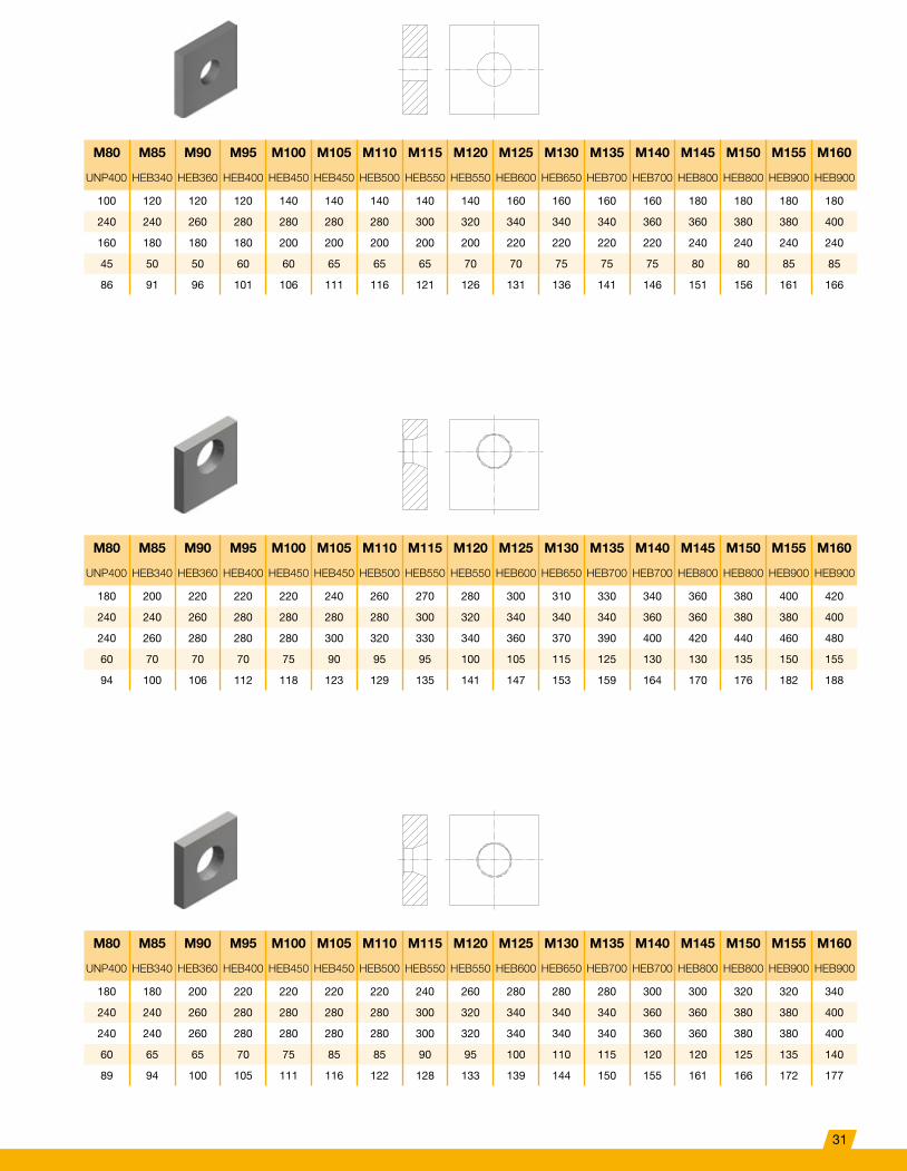
M80 M85 M90 M95 M100 M105 M110 M115 M120 M125 M130 M135 M140 M145 M150 M155 M160
UNP400 HEB340 HEB360 HEB400 HEB450 HEB450 HEB500 HEB550 HEB550 HEB600 HEB650 HEB700 HEB700 HEB800 HEB800 HEB900 HEB900
100 120 120 120 140 140 140 140 140 160 160 160 160 180 180 180 180
240 240 260 280 280 280 280 300 320 340 340 340 360 360 380 380 400
160 180 180 180 200 200 200 200 200 220 220 220 220 240 240 240 240
45 50 50 60 60 65 65 65 70 70 75 75 75 80 80 85 85
86 91 96 101 106 111 116 121 126 131 136 141 146 151 156 161 166
M80 M85 M90 M95 M100 M105 M110 M115 M120 M125 M130 M135 M140 M145 M150 M155 M160
UNP400 HEB340 HEB360 HEB400 HEB450 HEB450 HEB500 HEB550 HEB550 HEB600 HEB650 HEB700 HEB700 HEB800 HEB800 HEB900 HEB900
180 200 220 220 220 240 260 270 280 300 310 330 340 360 380 400 420
240 240 260 280 280 280 280 300 320 340 340 340 360 360 380 380 400
240 260 280 280 280 300 320 330 340 360 370 390 400 420 440 460 480
60 70 70 70 75 90 95 95 100 105 115 125 130 130 135 150 155
94 100 106 112 118 123 129 135 141 147 153 159 164 170 176 182 188
M80 M85 M90 M95 M100 M105 M110 M115 M120 M125 M130 M135 M140 M145 M150 M155 M160
UNP400 HEB340 HEB360 HEB400 HEB450 HEB450 HEB500 HEB550 HEB550 HEB600 HEB650 HEB700 HEB700 HEB800 HEB800 HEB900 HEB900
180 180 200 220 220 220 220 240 260 280 280 280 300 300 320 320 340
240 240 260 280 280 280 280 300 320 340 340 340 360 360 380 380 400
240 240 260 280 280 280 280 300 320 340 340 340 360 360 380 380 400
60 65 65 70 75 85 85 90 95 100 110 115 120 120 125 135 140
89 94 100 105 111 116 122 128 133 139 144 150 155 161 166 172 177
31
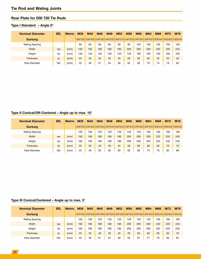
Tie Rod and Waling Joints
Rear Plate for DSI 720 Tie Rods
Type I Standard – Angle 0°
Nominal Diameter ØD1 Metric M39 M42 M45 M48 M52 M56 M60 M64 M68 M72 M76
Gurtung UNP260 UNP280 UNP280 UNP300 UNP320 UNP350 UNP380 UNP400 HEB340 HEB360 HEB400
Waling Spacing 80 80 80 80 80 80 100 100 100 100 100
Width wp [mm] 160 160 180 180 180 200 200 200 220 220 240
Height hp [mm] 140 140 140 140 140 140 160 160 160 160 160
Thickness tp [mm] 35 40 40 45 45 50 50 50 55 55 55
Hole Diameter Ød [mm] 45 48 51 54 58 62 66 70 74 78 82
Type II Conical/Off-Centered – Angle up to max. 10°
Nominal Diameter ØD1 Metric M39 M42 M45 M48 M52 M56 M60 M64 M68 M72 M76
Gurtung UNP260 UNP280 UNP280 UNP300 UNP320 UNP350 UNP380 UNP400 HEB340 HEB360 HEB400
Waling Spacing 100 100 120 120 120 140 140 160 160 180 180
Width wp [mm] 160 160 180 180 180 200 200 200 220 220 240
Height hp [mm] 160 160 180 180 180 200 200 220 220 240 240
Thickness tp [mm] 35 35 40 40 45 50 60 65 65 70 70
Hole Diameter Ød [mm] 45 49 52 56 60 65 69 74 79 83 88
Type III Conical/Centered – Angle up to max. 5°
Nominal Diameter ØD1 Metric M39 M42 M45 M48 M52 M56 M60 M64 M68 M72 M76
Gurtung UNP260 UNP280 UNP280 UNP300 UNP320 UNP350 UNP380 UNP400 HEB340 HEB360 HEB400
Waling Spacing 100 100 120 120 120 140 140 140 160 160 180
Width wp [mm] 160 160 180 180 180 200 200 200 220 220 240
Height hp [mm] 160 160 180 180 180 200 200 200 220 220 240
Thickness tp [mm] 35 35 40 40 45 50 60 60 65 65 70
Hole Diameter Ød [mm] 45 48 51 54 58 62 67 71 76 80 84
32
M80 M85 M90 M95 M100 M105 M110 M115 M120 M125 M130 M135 M140 M145 M150 M155 M160
HEB400 HEB450 HEB500 HEB550 HEB550 HEB550 HEB550 HEB600 HEB650 HEB700 HEB700 HEB800 HEB800 HEB900 HEB900 HEB1000 HEB1000
100 120 120 120 140 140 140 140 140 160 160 160 160 180 180 180 180
240 240 260 280 280 280 280 300 320 340 340 340 360 360 380 380 400
160 180 180 180 200 200 200 200 200 220 220 220 220 240 240 240 240
60 70 70 75 80 80 85 85 90 90 95 95 100 105 110 110 115
86 91 96 101 106 111 116 121 126 131 136 141 146 151 156 161 166
M80 M85 M90 M95 M100 M105 M110 M115 M120 M125 M130 M135 M140 M145 M150 M155 M160
HEB400 HEB450 HEB500 HEB550 HEB550 HEB550 HEB550 HEB600 HEB650 HEB700 HEB700 HEB800 HEB800 HEB900 HEB900 HEB1000 HEB1000
180 200 220 220 220 240 260 270 280 300 310 330 340 360 380 400 420
240 240 260 280 280 280 280 300 320 340 340 340 360 360 380 380 400
240 260 280 280 280 300 320 330 340 360 370 390 400 420 440 460 480
75 75 80 90 95 105 110 120 125 130 135 155 160 165 170 185 190
92 98 104 110 115 121 127 133 138 144 150 156 162 167 173 179 185
M80 M85 M90 M95 M100 M105 M110 M115 M120 M125 M130 M135 M140 M145 M150 M155 M160
HEB400 HEB450 HEB500 HEB550 HEB550 HEB550 HEB550 HEB600 HEB650 HEB700 HEB700 HEB800 HEB800 HEB900 HEB900 HEB1000 HEB1000
180 180 200 220 220 220 220 240 260 280 280 280 300 300 320 320 340
240 240 260 280 280 280 280 300 320 340 340 340 360 360 380 380 400
240 240 260 280 280 280 280 300 320 340 340 340 360 360 380 380 400
70 75 80 90 95 100 100 110 120 125 130 140 150 150 155 165 175
89 94 100 105 111 116 122 128 133 139 144 150 155 161 166 172 177
33
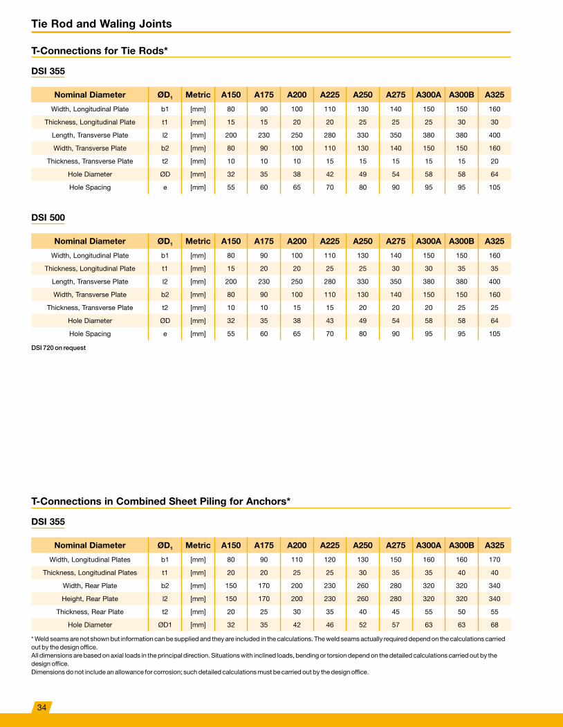
Tie Rod and Waling Joints
T-Connections for Tie Rods*
DSI 355
Nominal Diameter ØD1 Metric A150 A175 A200 A225 A250 A275 A300A A300B A325
Width, Longitudinal Plate b1 [mm] 80 90 100 110 130 140 150 150 160
Thickness, Longitudinal Plate t1 [mm] 15 15 20 20 25 25 25 30 30
Length, Transverse Plate l2 [mm] 200 230 250 280 330 350 380 380 400
Width, Transverse Plate b2 [mm] 80 90 100 110 130 140 150 150 160
Thickness, Transverse Plate t2 [mm] 10 10 10 15 15 15 15 15 20
Hole Diameter ØD [mm] 32 35 38 42 49 54 58 58 64
Hole Spacing e [mm] 55 60 65 70 80 90 95 95 105
DSI 500
Nominal Diameter ØD1 Metric A150 A175 A200 A225 A250 A275 A300A A300B A325
Width, Longitudinal Plate b1 [mm] 80 90 100 110 130 140 150 150 160
Thickness, Longitudinal Plate t1 [mm] 15 20 20 25 25 30 30 35 35
Length, Transverse Plate l2 [mm] 200 230 250 280 330 350 380 380 400
Width, Transverse Plate b2 [mm] 80 90 100 110 130 140 150 150 160
Thickness, Transverse Plate t2 [mm] 10 10 15 15 20 20 20 25 25
Hole Diameter ØD [mm] 32 35 38 43 49 54 58 58 64
Hole Spacing e [mm] 55 60 65 70 80 90 95 95 105
DSI 720 on request
T-Connections in Combined Sheet Piling for Anchors*
DSI 355
Nominal Diameter ØD1 Metric A150 A175 A200 A225 A250 A275 A300A A300B A325
Width, Longitudinal Plates b1 [mm] 80 90 110 120 130 150 160 160 170
Thickness, Longitudinal Plates t1 [mm] 20 20 25 25 30 35 35 40 40
Width, Rear Plate b2 [mm] 150 170 200 230 260 280 320 320 340
Height, Rear Plate l2 [mm] 150 170 200 230 260 280 320 320 340
Thickness, Rear Plate t2 [mm] 20 25 30 35 40 45 55 50 55
Hole Diameter ØD1 [mm] 32 35 42 46 52 57 63 63 68
* Weld seams are not shown but information can be supplied and they are included in the calculations� The weld seams actually required depend on the calculations carried out by the design office� All dimensions are based on axial loads in the principal direction� Situations with inclined loads, bending or torsion depend on the detailed calculations carried out by the design office� Dimensions do not include an allowance for corrosion; such detailed calculations must be carried out by the design office�
34
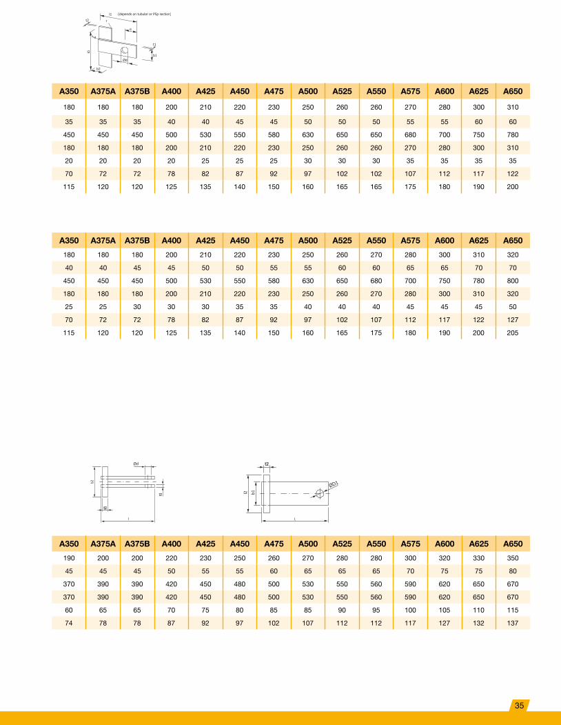
A350 A375A A375B A400 A425 A450 A475 A500 A525 A550 A575 A600 A625 A650
180 180 180 200 210 220 230 250 260 260 270 280 300 310
35 35 35 40 40 45 45 50 50 50 55 55 60 60
450 450 450 500 530 550 580 630 650 650 680 700 750 780
180 180 180 200 210 220 230 250 260 260 270 280 300 310
20 20 20 20 25 25 25 30 30 30 35 35 35 35
70 72 72 78 82 87 92 97 102 102 107 112 117 122
115 120 120 125 135 140 150 160 165 165 175 180 190 200
A350 A375A A375B A400 A425 A450 A475 A500 A525 A550 A575 A600 A625 A650
180 180 180 200 210 220 230 250 260 270 280 300 310 320
40 40 45 45 50 50 55 55 60 60 65 65 70 70
450 450 450 500 530 550 580 630 650 680 700 750 780 800
180 180 180 200 210 220 230 250 260 270 280 300 310 320
25 25 30 30 30 35 35 40 40 40 45 45 45 50
70 72 72 78 82 87 92 97 102 107 112 117 122 127
115 120 120 125 135 140 150 160 165 175 180 190 200 205
A350 A375A A375B A400 A425 A450 A475 A500 A525 A550 A575 A600 A625 A650
190 200 200 220 230 250 260 270 280 280 300 320 330 350
45 45 45 50 55 55 60 65 65 65 70 75 75 80
370 390 390 420 450 480 500 530 550 560 590 620 650 670
370 390 390 420 450 480 500 530 550 560 590 620 650 670
60 65 65 70 75 80 85 85 90 95 100 105 110 115
74 78 78 87 92 97 102 107 112 112 117 127 132 137
l1
r
e
t2
a
l2
b2
b1Ød
t1
(depends on tubular or PSp section)
t2
l
t1
b2
Ød
ØD1
t2
l2 b1
35
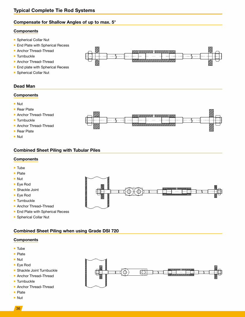
Typical Complete Tie Rod Systems
Compensate for Shallow Angles of up to max. 5°
Components
■ Spherical Collar Nut ■ End Plate with Spherical Recess ■ Anchor Thread–Thread ■ Turnbuckle ■ Anchor Thread–Thread ■ End plate with Spherical Recess ■ Spherical Collar Nut
Dead Man
Components
■ Nut ■ Rear Plate ■ Anchor Thread–Thread ■ Turnbuckle ■ Anchor Thread–Thread ■ Rear Plate ■ Nut
Combined Sheet Piling with Tubular Piles
Components
■ Tube ■ Plate ■ Nut ■ Eye Rod ■ Shackle Joint ■ Eye Rod ■ Turnbuckle ■ Anchor Thread–Thread ■ End Plate with Spherical Recess ■ Spherical Collar Nut
Combined Sheet Piling when using Grade DSI 720
Components
■ Tube ■ Plate ■ Nut ■ Eye Rod ■ Shackle Joint Turnbuckle ■ Anchor Thread–Thread ■ Turnbuckle ■ Anchor Thread–Thread ■ Plate ■ Nut
36
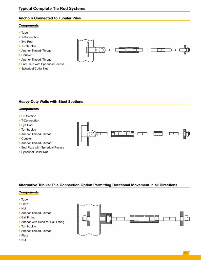
Typical Complete Tie Rod Systems
Anchors Connected to Tubular Piles
Components
■ Tube ■ T-Connection ■ Eye Rod ■ Turnbuckle ■ Anchor Thread–Thread ■ Coupler ■ Anchor Thread–Thread ■ End Plate with Spherical Recess ■ Spherical Collar Nut
Heavy-Duty Walls with Steel Sections
Components
■ HZ Section ■ T-Connection ■ Eye Rod ■ Turnbuckle ■ Anchor Thread–Thread ■ Coupler ■ Anchor Thread–Thread ■ End Plate with Spherical Recess ■ Spherical Collar Nut
Alternative Tubular Pile Connection Option Permitting Rotational Movement in all Directions
Components
■ Tube ■ Plate ■ Nut ■ Anchor Thread–Thread ■ Ball Fitting ■ Anchor with Head for Ball Fitting ■ Turnbuckle ■ Anchor Thread–Thread ■ Plate ■ Nut
37
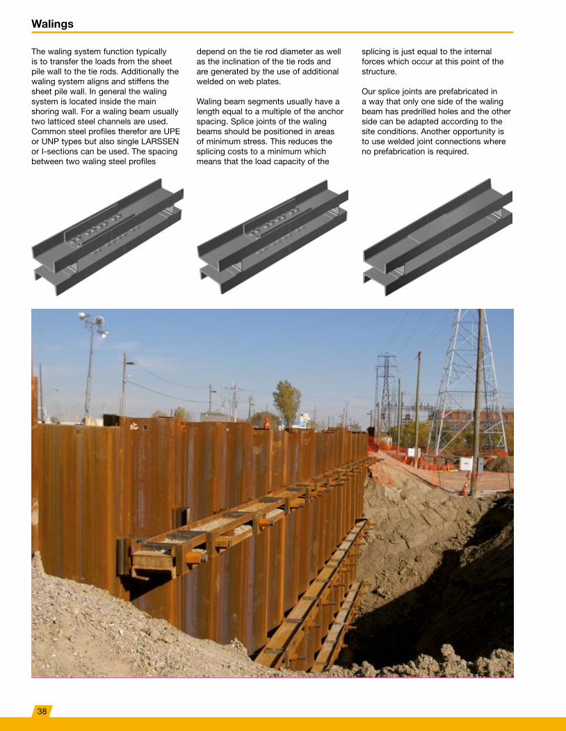
Walings
The waling system function typically is to transfer the loads from the sheet pile wall to the tie rods� Additionally the waling system aligns and stiffens the sheet pile wall� In general the waling system is located inside the main shoring wall� For a waling beam usually two latticed steel channels are used� Common steel profiles therefor are UPE or UNP types but also single LARSSEN or I-sections can be used� The spacing between two waling steel profiles
depend on the tie rod diameter as well as the inclination of the tie rods and are generated by the use of additional welded on web plates�
Waling beam segments usually have a length equal to a multiple of the anchor spacing� Splice joints of the waling beams should be positioned in areas of minimum stress� This reduces the splicing costs to a minimum which means that the load capacity of the
splicing is just equal to the internal forces which occur at this point of the structure�
Our splice joints are prefabricated in a way that only one side of the waling beam has predrilled holes and the other side can be adapted according to the site conditions� Another opportunity is to use welded joint connections where no prefabrication is required�
38

20
ca
b
f g h
l
e
g
][ UNP180 to UNP400 + UPE180 to UPE400
additional for ][ UNP280 to UNP350 + UPE270 to 360
additional for ][ UNP380 to UNP400 + UPE400
f
Walings
Waling Splice Joint
][ Waling Splicing piece ][ Dimensions Bolts, DIN 933 Nut Wash-
er Weight
Wy [kg]/m ][ | [kg] a b c e Ø f g h No. Size L DIN 934DIN 125
[kg]
[cm3] [mm] [mm] [mm] [mm] [mm] [mm] [mm] [mm] [mm]
UNP180 300 44 UNP120 560 14�9 37�5 45 67�5 22 40 60 80 32 M20 45Ø37/
Ø21 x 3M20 8
UNP200 382 50�6 UNP140 640 20�5 40 60 70 22 40 60 120 32 M20 45Ø37/
Ø21 x 3M20 8
UNP220 490 58�8 UNP160 680 25�7 40 80 70 22 40 60 140 32 M20 45Ø37/
Ø21 x 3M20 8
UNP240 600 66�4 UNP180 740 32�6 45 90 75 26 50 75 120 32 M24 50Ø44/
Ø25 x 4M24 13
UNP260 742 75�8 UNP200 800 40�5 45 110 75 26 50 75 150 32 M24 50Ø44/
Ø25 x 4M24 13
UNP280 892 83�8 UNP220 840 49�4 50 120 80 26 50 90 140 40 M24 55Ø44/
Ø25 x 4M24 16
UNP300 1,070 92�4 UNP220 920 54�1 50 120 90 26 50 90 180 40 M24 55Ø44/
Ø25 x 4 M24 16
UNP320 1,360 119 UNP240 1,000 66�4 55 130 95 32 60 110 160 40 M30 65Ø56/
Ø31 x 4 M30 35
UNP350 1,468 121�2 UNP260 1,000 75�8 60 140 105 32 60 110 160 40 M30 65Ø56/
Ø31 x 4 M30 35
UNP380 1,660 126�2 UNP300 1,000 92�2 60 180 100 32 60 90 200 48 M30 65Ø56/
Ø31 x 4 M30 42
UNP400 2,040 143�6 UNP300 1,000 92�2 60 180 110 32 60 90 200 48 M30 65Ø56/
Ø31 x 4 M30 42
UPE180 301 39�5 UPE120 560 13�6 37�5 45 67�5 22 40 60 80 32 M20 45Ø37/
Ø21 x 3 M20 8
UPE200 382 45�6 UPE140 640 18�6 40 60 70 22 40 60 120 32 M20 45Ø37/
Ø21 x 3 M20 8
UPE220 488 53�2 UPE160 680 23�2 40 80 70 22 40 60 140 32 M20 45Ø37/
Ø21 x 3 M20 8
UPE240 600 60�5 UPE180 740 29�2 45 90 75 26 50 75 120 32 M24 50Ø44/
Ø25 x 4 M24 13
UPE270 780 70�4 UPE200 840 38�3 45 110 80 26 50 90 140 40 M24 55Ø44/
Ø25 x 4 M24 16
UPE300 1,043 88�9 UPE220 920 49 50 120 90 26 50 90 180 40 M24 55Ø44/
Ø25 x 4 M24 16
UPE330 1,335 106�4 UPE240 1,000 60�5 55 130 100 32 60 110 160 40 M30 65Ø56/
Ø31 x 4 M30 35
UPE360 1,648 122�4 UPE270 1,000 70�4 65 140 110 32 60 110 160 40 M30 65Ø56/
Ø31 x 4 M30 35
UPE400 2,098 144�4 UPE300 1,000 88�9 60 180 110 32 60 90 200 48 M30 65Ø56/
Ø31 x 4 M30 42
Steel grade: S235JR / S355
39
b
h
t = 10 mm
Walings
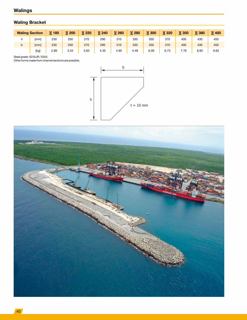
Waling Bracket
Waling Section ][ 180 ][ 200 ][ 220 ][ 240 ][ 260 ][ 280 ][ 300 ][ 320 ][ 350 ][ 380 ][ 400
h [mm] 230 250 270 290 310 330 350 370 400 430 450
b [mm] 230 250 270 290 310 330 350 370 400 430 450
[kg] 2�89 3�34 3�83 4�35 4�90 5�48 6�09 6�73 7�76 8�85 9�62
Steel grade: S235JR / S355 Other forms made from channel sections are possible�
40

lg
D
l
Walings
Waling Bolt with Head and Nut
D Metric M27 M33 M39 M45 M52 M56 M64 M72 M76 M85 M90
][ 200l [mm] 320 320 340 360
lg [mm] 85 95 105 115[kg] 1�54 2�50 3�88 5�61
][ 220l [mm] 340 340 360 380 400
lg [mm] 85 95 105 115 125[kg] 1�62 2�62 4�05 5�83 8�21
][ 240l [mm] 360 360 380 400 420 420 440 460
lg [mm] 85 95 105 115 125 130 135 140[kg] 1�70 2�73 4�22 6�06 8�51 10�06 13�67 18�08
][ 260l [mm] 380 380 400 420 440 440 460 480 500 510 530
lg [mm] 85 95 105 115 125 130 135 140 145 150 155[kg] 1�77 2�85 4�39 6�29 8�80 10�41 14�11 18�65 22�72 28�88 34�24
][ 280l [mm] 400 400 420 440 460 460 480 500 520 530 550
lg [mm] 85 95 105 115 125 130 135 140 145 150 155[kg] 1�85 2�97 4�56 6�52 9�10 10�76 14�56 19�23 23�36 29�69 35�16
][ 300l [mm] 420 440 460 480 480 500 520 540 550 570
lg [mm] 95 105 115 125 130 135 140 145 150 155[kg] 3�09 4�73 6�75 9�39 11�10 15 19�80 24 30�50 36�07
][ 320l [mm] 440 460 480 500 500 520 540 560 570 590
lg [mm] 95 105 115 125 130 135 140 145 150 155[kg] 3�21 4�89 6�97 9�69 11�45 15�44 20�32 24�64 31�31 36�98
][ 350l [mm] 490 510 530 530 550 570 590 600 620
lg [mm] 105 115 125 130 135 140 145 150 155[kg] 5�15 7�32 10�13 11�97 16�11 21�22 25�60 32�53 38�35
][ 380l [mm] 520 540 560 560 580 600 620 630 650
lg [mm] 105 115 125 130 135 140 145 150 155[kg] 5�40 7�66 10�58 12�49 16�78 22�08 26�56 33�74 39�72
][ 400l [mm] 540 560 580 580 600 620 640 650 670
lg [mm] 105 115 125 130 135 140 145 150 155[kg] 5�57 7�89 10�88 12�84 17�22 22�65 27�20 34�58 40�63
Steel grade: S355 / S355J2+N The weight includes the nut Also available in ASF500 / 8�8 / 10�9
41

lg
l
lg
D
Walings
Waling Stud with two Nuts
D Metric M27 M33 M39 M45 M52 M56 M64 M72 M76 M85 M90
][ 200l [mm] 350 380 400 440
lg [mm] 85 95 105 115[kg] 1�65 2�86 4�38 6�42
][ 220l [mm] 380 410 430 460 480
lg [mm] 85 95 105 115 125[kg] 1�77 3�03 4�63 6�65 9�31
][ 240l [mm] 390 420 440 470 510 510 530 560 580 600 630
lg [mm] 85 95 105 115 125 130 135 140 145 150 155[kg] 1�81 3�09 4�72 6�76 9�75 11�64 15�57 20�77 24�34 31�88 37�93
][ 260l [mm] 410 440 460 490 530 530 550 580 600 620 650
lg [mm] 85 95 105 115 125 130 135 140 145 150 155[kg] 1�88 3�21 4�89 6�99 10�05 11�98 16�01 21�34 24�98 32�68 38�84
][ 280l [mm] 430 460 480 510 550 550 570 600 620 640 670
lg [mm] 85 95 105 115 125 130 135 140 145 150 155[kg] 1�96 3�33 5�06 7�22 10�35 12�33 16�96 21�91 25�62 33�49 39�76
][ 300l [mm] 480 510 540 570 570 600 620 640 660 690
lg [mm] 95 105 115 125 130 135 140 145 150 155[kg] 3�45 5�31 7�56 10�64 12�68 17�12 22�48 26�26 34�80 40�67
][ 320l [mm] 530 560 590 590 620 640 660 680 710
lg [mm] 105 115 125 130 135 140 145 150 155[kg] 5�48 7�79 10�94 13�02 17�57 23�05 26�90 35�11 41�58
][ 350l [mm] 550 580 620 620 640 660 680 710 740
lg [mm] 105 115 125 130 135 140 145 150 155[kg] 5�65 8�02 11�38 13�54 18�01 23�62 27�54 36�33 42�95
][ 380l [mm] 580 610 650 650 670 680 710 740 770
lg [mm] 105 115 125 130 135 140 145 150 155[kg] 5�90 8�36 11�83 14�06 18�68 24�19 28�50 37�54 44�32
][ 400l [mm] 600 630 670 670 690 700 730 760 790
lg [mm] 105 115 125 130 135 140 145 150 155[kg] 6�07 8�59 12�12 14�41 19�12 24�76 29�14 38�35 45�23
Steel grade: S355 / S355J2+N The weight includes the nut Also available in ASF500 / 8�8 / 10�9
42
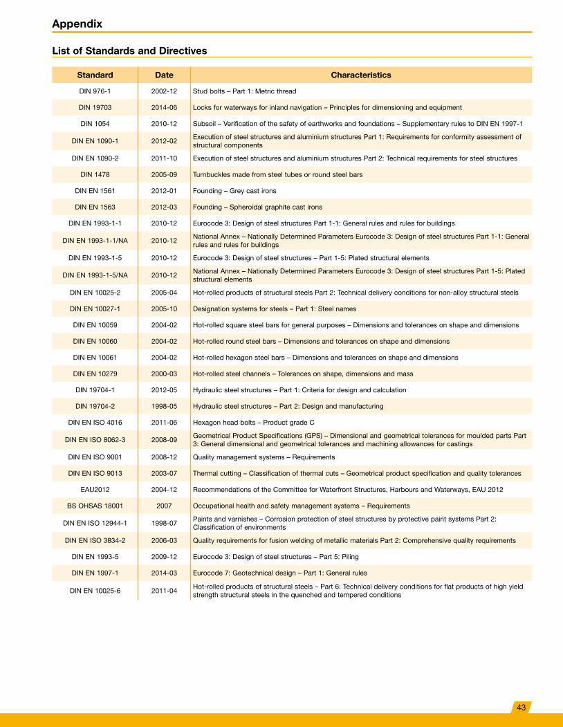
Appendix
List of Standards and Directives
Standard Date Characteristics
DIN 976-1 2002-12 Stud bolts – Part 1: Metric thread
DIN 19703 2014-06 Locks for waterways for inland navigation – Principles for dimensioning and equipment
DIN 1054 2010-12 Subsoil – Verification of the safety of earthworks and foundations – Supplementary rules to DIN EN 1997-1
DIN EN 1090-1 2012-02Execution of steel structures and aluminium structures Part 1: Requirements for conformity assessment of structural components
DIN EN 1090-2 2011-10 Execution of steel structures and aluminium structures Part 2: Technical requirements for steel structures
DIN 1478 2005-09 Turnbuckles made from steel tubes or round steel bars
DIN EN 1561 2012-01 Founding – Grey cast irons
DIN EN 1563 2012-03 Founding – Spheroidal graphite cast irons
DIN EN 1993-1-1 2010-12 Eurocode 3: Design of steel structures Part 1-1: General rules and rules for buildings
DIN EN 1993-1-1/NA 2010-12National Annex – Nationally Determined Parameters Eurocode 3: Design of steel structures Part 1-1: General rules and rules for buildings
DIN EN 1993-1-5 2010-12 Eurocode 3: Design of steel structures – Part 1-5: Plated structural elements
DIN EN 1993-1-5/NA 2010-12National Annex – Nationally Determined Parameters Eurocode 3: Design of steel structures Part 1-5: Plated structural elements
DIN EN 10025-2 2005-04 Hot-rolled products of structural steels Part 2: Technical delivery conditions for non-alloy structural steels
DIN EN 10027-1 2005-10 Designation systems for steels – Part 1: Steel names
DIN EN 10059 2004-02 Hot-rolled square steel bars for general purposes – Dimensions and tolerances on shape and dimensions
DIN EN 10060 2004-02 Hot-rolled round steel bars – Dimensions and tolerances on shape and dimensions
DIN EN 10061 2004-02 Hot-rolled hexagon steel bars – Dimensions and tolerances on shape and dimensions
DIN EN 10279 2000-03 Hot-rolled steel channels – Tolerances on shape, dimensions and mass
DIN 19704-1 2012-05 Hydraulic steel structures – Part 1: Criteria for design and calculation
DIN 19704-2 1998-05 Hydraulic steel structures – Part 2: Design and manufacturing
DIN EN ISO 4016 2011-06 Hexagon head bolts – Product grade C
DIN EN ISO 8062-3 2008-09Geometrical Product Specifications (GPS) – Dimensional and geometrical tolerances for moulded parts Part 3: General dimensional and geometrical tolerances and machining allowances for castings
DIN EN ISO 9001 2008-12 Quality management systems – Requirements
DIN EN ISO 9013 2003-07 Thermal cutting – Classification of thermal cuts – Geometrical product specification and quality tolerances
EAU2012 2004-12 Recommendations of the Committee for Waterfront Structures, Harbours and Waterways, EAU 2012
BS OHSAS 18001 2007 Occupational health and safety management systems – Requirements
DIN EN ISO 12944-1 1998-07Paints and varnishes – Corrosion protection of steel structures by protective paint systems Part 2: Classification of environments
DIN EN ISO 3834-2 2006-03 Quality requirements for fusion welding of metallic materials Part 2: Comprehensive quality requirements
DIN EN 1993-5 2009-12 Eurocode 3: Design of steel structures – Part 5: Piling
DIN EN 1997-1 2014-03 Eurocode 7: Geotechnical design – Part 1: General rules
DIN EN 10025-6 2011-04Hot-rolled products of structural steels – Part 6: Technical delivery conditions for flat products of high yield strength structural steels in the quenched and tempered conditions
43
0444
9-1/
10�1
7-30
0 sc
ho
A R G E N T I N AA U S T R A L I A
A U S T R I AB E L G I U M
B O S N I A A N D H E R Z E G O V I N AB R A Z I L
C A N A D AC H I L EC H I N A
C O L O M B I AC O S TA R I C A
C R O AT I AC Z E C H R E P U B L I C
D E N M A R KE G Y P T
E S T O N I AF I N L A N DF R A N C E
G E R M A N YG R E E C E
G U AT E M A L AH O N D U R A S
H O N G K O N GI N D I A
I N D O N E S I AI R A N
I TA LYJ A PA NK O R E A
L E B A N O NL U X E M B O U R G
M A L AY S I AM E X I C O
N E T H E R L A N D SN I G E R I AN O R W AY
O M A NPA N A M A
PA R A G U AYP E R U
P O L A N DP O R T U G A L
Q ATA RR U S S I A
S A U D I A R A B I AS I N G A P O R E
S O U T H A F R I C AS PA I N
S W E D E NS W I T Z E R L A N D
TA I W A NT H A I L A N D
T U R K E YU N I T E D A R A B E M I R AT E S
U N I T E D K I N G D O MU R U G U AY
U S AV E N E Z U E L A
AustriaDSI Underground Austria GmbH Alfred-Wagner-Strasse 1 4061 Pasching/Linz Austria Phone +43-7229-610 49-0 E-mail info�austria@dsiunderground�at www�dsiunderground�at
BelgiumDYWIDAG-Systems International N�V� Philipssite 5, bus 15 Ubicenter 3001 Leuven Belgium Phone +32-16-60 77 60 E-mail info�be@dywidag-systems�com www�dywidag-systems�com/emea
FranceDSI France SAS Rue de la Craz Z�I� des Chartinières 01120 Dagneux France Phone +33-4-78 79 27 82 E-mail dsi�france@dywidag-systems�fr www�dywidag-systems�fr
GermanyDYWIDAG-Systems International GmbH Germanenstrasse 8 86343 Koenigsbrunn Germany Phone +49-8231-96 07-0 E-mail geotechnik@dywidag-systems�com www�dywidag-systems�de
ItalyDYWIT S�P�A� Viale Europa 72 Strada A 7/9 20090 Cusago (Milano) Italy Phone +39-02-901 65 71 E-mail info@dywit�it www�dywit�it
NetherlandsDYWIDAG-Systems International B�V� Veilingweg 2 5301 KM Zaltbommel Netherlands Phone +31-418-57 89 22 E-mail email�nl@dywidag-systems�com www�dywidag-systems�nl
PolandDYWIDAG-Systems International Sp� z o�o� ul� Bojowników o Wolnos´c´ i Demokracje˛ 38/121 41-506 Chorzów Poland Phone +48-32-241 09 98 E-mail dsi-polska@dywidag-systems�com www�dywidag-systems�pl
PortugalDYWIDAG SISTEMAS CONSTRUCTIVOS, SA Rua D� Manuel, n�º 24 A Quinta da Parreirinha 2695-003 Bobadela (Loures) Portugal Phone +351-21-892 28 90 E-mail dywidag@dywidag-sistemas�com www�dywidag-systems�pt
SpainDYWIDAG SISTEMAS CONSTRUCTIVOS, S�A� Avd/de la Industria, 4 Pol� Ind� la Cantuena 28947 Fuenlabrada (Madrid) Spain Phone +34-91-642 20 72 E-mail dywidag@dywidag-sistemas�com www�dywidag-sistemas�com
United KingdomDYWIDAG-Systems International Ltd� Northfield Road Southam, Warwickshire, CV47 0FG Great Britain Phone +44-1926-81 39 80 E-mail sales@dywidag�co�uk www�dywidag�co�uk
ChinaDYWIDAG-Systems International Far East Ltd� 9/F, Prosperity Millennia Plaza, Unit 905-907 663 King’s Road, North Point Hong Kong Phone +852-28-33 19 13 E-mail dsihk@dsife�com�hk www�dywidag-systems�com/emea
IndiaDSI-BRIDGECON Pvt� Ltd� 265, Okhla Industrial Estate, Phase 3 110020 New Delhi India Phone +974-44-58 04 11 E-mail info@dsi-bridgecon�com www�dsi-bridgecon�com
KoreaDYWIDAG-Systems Korea Co� Ltd� 5th Floor, Spring Morning B/D 8, Mabang-ro, Seocho-gu Seoul 137-894 Korea Phone +82-2-34 72 01 41 E-mail dywidagkor@gmail�com www�dsikorea�co�kr
QatarDYWIDAG-Systems Middle East W�L�L� Al Shoumoukh Towers 11th Floor Street 231 Building no 58 Area no 23, Suhaim Bin Hamed Doha P�O�Box 24893 Doha / Qatar Phone +974-44-58 04 11 E-mail info�qatar@dsi-middleeast�com www�dsi-middleeast�com
Saudi ArabiaDYWIDAG-Systems Int� Saudi Arabia, LLC P�O� Box 64014 Riyadh-Olaya 11536 Saudi Arabia Phone +966-11-455 3123 E-mail dsihv@dywidag-systems�com www�dywidag-systems�com/emea
www.dywidag-systems.com/emea
Please Note: This brochure serves basic information purposes only� Technical data and information provided herein shall be considered non-binding and may be subject to change without notice� We do not assume any liability for losses or damages attributed to the use of this technical data and any improper use of our products� Should you require further information on particular products, please do not hesitate to contact us�