dynamic voltage restorer frame work to improve … · 2018-10-11 · abstract - a dynamic voltage...
TRANSCRIPT

International Research Journal of Engineering and Technology (IRJET) e-ISSN: 2395-0056
Volume: 05 Issue: 10 | Oct 2018 www.irjet.net p-ISSN: 2395-0072
© 2018, IRJET | Impact Factor value: 7.211 | ISO 9001:2008 Certified Journal | Page 435
DYNAMIC VOLTAGE RESTORER FRAME WORK TO IMPROVE POWER
QUALITY OF THE DISTRIBUTION GRID BASED ON ENERGY
STORAGE SYSTEM
C.SUBBARAJU1, M.LOKANADHAM2, S.VENKATARAO3, P.RAVINDRA PRASAD4
1M. Tech Student, Electrical Power Systems, Sri Venkatesa Perumal College of Engineering and Technology, R.V.S. Nagar, K.N. Road, Puttur – 517 583, Chittoor (Dt.) A.P.India.
2,3Assistant Professor, EEE Department , Sri Venkatesa Perumal College of Engineering and Technology, R.V.S. Nagar, K.N. Road, Puttur – 517 583, Chittoor (Dt.) A.P.India.
-------------------------------------------------------------------------***-----------------------------------------------------------------------Abstract - A Dynamic Voltage Restorer (DVR) is one of the best solutions for power quality problems like voltage sags and swells, but the individual DVR usage have no capability to control the active power injection into the grid. In order to have such a control and to compensate the problem of voltage sag, a lagging voltage to be injected, which is in quadrature with the line current i.e., it needs a penetration of rechargeable energy storage at DC-terminal of DVR. In the literature there are many types of rechargeable energy storage technologies like Flywheels (FESS), Super Conducting Magnets (SMES) are integrated. Each of the technologies have their own merits and demerits. In this paper active power is controlled through integration of rechargeable energy storage. For this type of application, rechargeable Ultra Capacitors (UCAP) are to be integrated, this integration of UCAP & DVR system is the best suit for the active power support in the milliseconds to seconds range. Since the ultra-capacitors can exhibit low-energy density and high energy density capabilities. It can be capable of handling the both type issues of sags and swells. Also this integration have active power capability and compensate temporary voltage sags and swells without relying on the grid.
But the design and control of the DC-DC converter is a complex task but in this work those complexities are also discussed and average current mode control is used to regulate the output voltage of DC-DC converters. Both DC-AC converter and the DC-DC converter are discussed. The simulation model of the overall system is developed in MATLAB software.
Key Words: Keywords: DC–DC converter, d–q control, DSP, dynamic voltage restorer (DVR), energy storage integration, phase locked loop (PLL), sag/swell, Ultra capacitor (UCAP).
1. INTRODUCTION
Cost of various energy storage technologies is decreasing rapidly and the integration of these technologies into the power grid is becoming a reality with the advent of smart grid. DVR is a one product that can provide improved voltage sag and swell compensation with energy storage integration [1]. Ultra-Capacitor (UCAP) is a energy storage device, which can be integrated to inverter based DVR for preventing momentary disturbances in the utility side.
The concept of using inverter-based dynamic voltage restorers (DVRs) for preventing customers from momentary voltage disturbances on the utility side the concept of using the DVR as a power quality product has gained significant popularity since its first use. In, the authors propose the usage of the DVR with rechargeable energy storage at the dc-terminal to meet the active power requirements of the grid during voltage disturbances. In order to avoid and minimize the active power injection into the grid [2], the authors also mention an alternative solution which is to compensate for the voltage sag by inserting a lagging voltage in quadrature with the line current.
The control strategies have also been developed to minimize the active power injection from the DVR. The high cost of the rechargeable energy storage prevents the penetration of the DVR as a power quality product. However, the cost of rechargeable energy storage has been decreasing drastically in the recent past due to various technological developments and due to higher penetration in the market in the form of auxiliary energy storage for distributed energy resources (DERs) such as wind, solar, hybrid electric vehicles (HEVs), and plug-in hybrid electric vehicle (PHEVs). Therefore, there has been renewed interest in the literature [3] to integrate rechargeable energy storage again at the dc-terminal of power quality products such as static compensator (STATCOM) and DVR. Various types of rechargeable energy storage technologies based on superconducting magnets (SMES), flywheels (FESS), batteries (BESS), and ultra-capacitors (UCAPs) are compared in [4] for integration into advanced power applications such as DVR. In [5], the authors propose the usage of the DVR with rechargeable energy storage at the dc-terminal to meet the active power requirements of the grid during voltage disturbances. In order to avoid and minimize the active power injection into the grid, the authors also mention an alternative solution which is to compensate for the voltage sag by inserting a lagging voltage in quadrature

International Research Journal of Engineering and Technology (IRJET) e-ISSN: 2395-0056
Volume: 05 Issue: 10 | Oct 2018 www.irjet.net p-ISSN: 2395-0072
© 2018, IRJET | Impact Factor value: 7.211 | ISO 9001:2008 Certified Journal | Page 436
with the line current. Due to the high cost of rechargeable energy storage, various other types of control strategies have also been developed in the literature [6]–[12] to minimize the active power injection from the DVR.
The high cost of the rechargeable energy storage prevents the penetration of the DVR as a power quality product. However, the cost of rechargeable energy storage has been decreasing drastically in the recent past due to various technological developments and due to higher penetration in the market in the form of auxiliary energy storage for distributed energy resources (DERs) such as wind, solar, hybrid electric vehicles (HEVs), and plug-in hybrid electric vehicle (PHEVs) [13], [14]. Therefore, there has been renewed interest in the literature [15]–[18] to integrate rechargeable energy storage again at the dc-terminal of power quality products such as static compensator (STATCOM) and DVR.
In this paper, UCAP-based energy storage integration to a DVR into the distribution grid is proposed and the following application areas are addressed.
1. To design the integration of Ultra Capacitor-Dynamic Voltage Restorer (UCAP-DVR) for improving active power capability to compensate the temporary voltage sags and swells.
2. To improve the voltage restoration capabilities at the UCAP-DVR system.
2. SINGLE LINE DIAGRAM OF DVR WITH UCAP:
Fig.1 Single Line diagram of DVR with UCAP energy storage
The single line diagram UCAP with energy storage is as shown in Fig.1. In this circuit contains Dynamic Voltage Restorer with a Ultra capacitor, it injecting the external power to the transmission line. The Ultra Capacitor provides DC supply to the boost converter. It is a DC-DC converter converts fixed DC input into variable (greater than or less than) input voltage. Then the capacitor can be used reduce the harmonics in the output voltage then it is converted into the AC by means of series inverter.
A UCAP cannot be directly connected to the dc-link of the inverter like a battery, as the voltage profile of the UCAP varies as it discharges energy.
Therefore, there is a need to integrate the UCAP system through a bidirectional dc–dc converter, which maintains a stiff dc-link voltage, as the UCAP voltage decreases while discharging and increases while charging.
The model of three phase inverter DVR as shown in Fig.2. and The model of the bidirectional dc–dc converter and its controller are shown in Fig.3. where the input consists of three UCAPs connected in series and the output consists of a nominal load 213.5 Ω to prevent operation at no-load, and the output is connected to the dc-link of the inverter. The amount of active power support required by the grid during a voltage sag event is dependent on the depth and duration of the voltage sag, and the dc–dc converter should be able to withstand this power during the discharge mode.

International Research Journal of Engineering and Technology (IRJET) e-ISSN: 2395-0056
Volume: 05 Issue: 10 | Oct 2018 www.irjet.net p-ISSN: 2395-0072
© 2018, IRJET | Impact Factor value: 7.211 | ISO 9001:2008 Certified Journal | Page 437
3. MODEL OF THREE-PHASE SERIES INVERTER (DVR):
Fig.2. Model of three phase inverter
The inverter system consists of an insulated gate bipolar transistor (IGBT) module, its gate-driver, LC filter, and an isolation transformer. The dc-link voltage Vdc is regulated at 260 V for optimum performance of the converter and the line–line voltage Vab is 208 V; based on these, the modulation index m of the inverter is given by
m = ,,,,,,,,,,,,,,,,,,,,,,,,,,,,,eqn (1)
where n is the turns ratio of the isolation transformer. Substituting n as 2.5 in eqn (1), the required modulation index is calculated as 0.52. Therefore, the output of the dc–dc converter should be regulated at 260 V for providing accurate voltage compensation. The objective of the integrated UCAPDVR system with active power capability is to compensate for temporary voltage sags and voltage swell.
4. CONTROLLER IMPLEMENTATION:
Fig.3. controller implementation of three phase inverter
As shown in Fig.3. there are various methods to control the series inverter to provide and most of them rely on injecting a voltage in quadrature with advanced phase, so that reactive power is utilized in voltage restoration. Phase advanced voltage restoration techniques are complex in implementation, but the primary reason for using these techniques dynamic voltage restoration is to minimize the active power support and thereby the amount of energy storage requirement at the dc-link in order to minimize the cost of energy storage. However, the cost of energy storage has been
VV
rmsab
dcn
)(*3
22

International Research Journal of Engineering and Technology (IRJET) e-ISSN: 2395-0056
Volume: 05 Issue: 10 | Oct 2018 www.irjet.net p-ISSN: 2395-0072
© 2018, IRJET | Impact Factor value: 7.211 | ISO 9001:2008 Certified Journal | Page 438
declining and with the availability of active power support at the dc-link, complicated phase-advanced techniques can be avoided and voltages can be injected in-phase with the system voltage during a voltage sag or a swell event. The control method requires the use of a PLL to find the rotating angle. the goal of this project is to use the active power capability of the UCAP-DVR system and compensate temporary voltage sags and swells.
The inverter controller implementation is based on injecting voltages in-phase with the supply-side line–neutral voltages. This requires PLL for estimating θ, which has been implemented using the fictitious power method. Based on the estimated θ and the line–line source voltages, Vab, Vbc, and Vca (which are available for this delta-sourced system) are transformed into the d–q domain and the line– neutral components of the source voltage Vsa, Vsb, and Vsc, which are not available, can then be estimated using
[
]
[
√
√
]
[ (
) (
)
(
) (
)] [
√
√
] eqn (2)
[
]
[ (
)
( (
)
)
( (
)
)]
.eqn (3)
( ) ( ) eqn (4)
( ) ( )
Therefore, whenever there is a voltage sag or swell on the source side, a corresponding voltage Vinj2 is injected in-phase by the DVR and UCAP system to negate the effect and retain a constant voltage VL at the load end. The actual active and reactive power supplied by the series inverter can be computed from the rms values of the injected voltage Vinj2a and load current ILa, and ϕ is the phase difference between the two waveforms.
5. PHASE LOCKED LOOP:
As shown in Fig.5. Phase-locked loop (PLL) is a control system that generates a signal that has a fixed relation to the phase of a "reference" signal. A phase-locked loop circuit responds to both the frequency and the phase of the input signals, automatically raising or lowering the frequency of a controlled oscillator until it is matched to the reference in both frequency and phase.
A PLL is a control loop consisting of three fundamental components, as shown in figure These are a phase detector or phase comparator (PD), a loop filter (LF) and a voltage controlled oscillator (VCO). The phase detector compares the phase of a periodic input signal against the phase of the fed-back output signal. The phase detector output is a measure of phase error between its two applied inputs. The error voltage is then filtered by the loop filter, whose control output is then applied to the VCO. The control voltage changes the VCO frequency in a direction that reduces the phase error between the input signal and the VCO.
Fig.4. Functional Block diagram of PLL

International Research Journal of Engineering and Technology (IRJET) e-ISSN: 2395-0056
Volume: 05 Issue: 10 | Oct 2018 www.irjet.net p-ISSN: 2395-0072
© 2018, IRJET | Impact Factor value: 7.211 | ISO 9001:2008 Certified Journal | Page 439
Fig.5. Block diagram of PLL used to measure Phase Angle
6. SIMULATION RESULTS:
The simulation of the proposed UCAP-integrated DVR system is carried out in MATLAB. In proposed system we are using two controllers:
1. Fuzzy logic controller is used in DC-DC converter and 2. PI controller is used in DVR.
FIG.6.SIMULINK MODEL

International Research Journal of Engineering and Technology (IRJET) e-ISSN: 2395-0056
Volume: 05 Issue: 10 | Oct 2018 www.irjet.net p-ISSN: 2395-0072
© 2018, IRJET | Impact Factor value: 7.211 | ISO 9001:2008 Certified Journal | Page 440
Waveforms during voltage sag:
Peak voltages during sag:
Fig.6.1 Source and load peak voltages VSmax (Blue) and VLmax during sag(Green)
Sag voltage:
Fig.6.2 Source voltages Vsa (blue), Vsb (red), and Vsc (green) during sag
DVR injected voltage:
Fig.6.3 Injected voltages Vinj2a (blue), Vinj2b (red), and Vinj2c (green) during sag

International Research Journal of Engineering and Technology (IRJET) e-ISSN: 2395-0056
Volume: 05 Issue: 10 | Oct 2018 www.irjet.net p-ISSN: 2395-0072
© 2018, IRJET | Impact Factor value: 7.211 | ISO 9001:2008 Certified Journal | Page 441
Load voltage:
Fig.6.4 Load voltages VLa (blue), VLb (red), and VLc (green) during sag
Voltages of capacitors:
Fig.6.5 Voltages of dc–dc converter in Capacitor 44µF (Blue) and Capacitor 55F (Green) during voltage sag
Currents of capacitors:
Fig.6.6 Ultra-capacitor current Iuc (Blue) and Capacitor current Idc of DC-DC Converter (Green) of dc–dc converter during
voltage sag
Comparison of DVR voltage and system voltage:
Fig.6.7 Vinj2a (green) and Vsa (blue) waveforms during sag
International Research Journal of Engineering and Technology (IRJET) e-ISSN: 2395-0056
Volume: 05 Issue: 10 | Oct 2018 www.irjet.net p-ISSN: 2395-0072
© 2018, IRJET | Impact Factor value: 7.211 | ISO 9001:2008 Certified Journal | Page 442
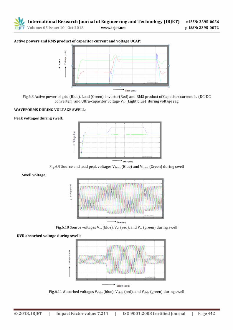
Active powers and RMS product of capacitor current and voltage UCAP:
Fig.6.8 Active power of grid (Blue), Load (Green), inverter(Red) and RMS product of Capacitor current Idc (DC-DC
converter) and Ultra-capacitor voltage Vdc (Light blue) during voltage sag
WAVEFORMS DURING VOLTAGE SWELL:
Peak voltages during swell:
Fig.6.9 Source and load peak voltages VSmax (Blue) and VLmax (Green) during swell
Swell voltage:
Fig.6.10 Source voltages Vsa (blue), Vsb (red), and Vsc (green) during swell
DVR absorbed voltage during swell:
Fig.6.11 Absorbed voltages Vob2a (blue), Vob2b (red), and Vob2c (green) during swell
Wat
ts

International Research Journal of Engineering and Technology (IRJET) e-ISSN: 2395-0056
Volume: 05 Issue: 10 | Oct 2018 www.irjet.net p-ISSN: 2395-0072
© 2018, IRJET | Impact Factor value: 7.211 | ISO 9001:2008 Certified Journal | Page 443
Load voltage:
Fig.6.12 Load voltages VLa (blue), VLb (red), and VLc (green) during swell
Voltages of capacitor:
Fig.6.13 Voltages of dc–dc converter in Capacitor 44µF (Blue) and Capacitor 55F (Green) during voltage sag
Currents of capacitor:
Fig.6.14 DC Link of DC-DC converter (Blue) and UCAP Current (Green) During Voltage Swell
Comparison of DVR voltage and system voltage:
Fig.6.15 Vob2a (green) and Vsa (blue) waveforms during swell

International Research Journal of Engineering and Technology (IRJET) e-ISSN: 2395-0056
Volume: 05 Issue: 10 | Oct 2018 www.irjet.net p-ISSN: 2395-0072
© 2018, IRJET | Impact Factor value: 7.211 | ISO 9001:2008 Certified Journal | Page 444
Active powers and RMS product of capacitor current and UCAP voltage:
Fig.6.16 Active power of grid (Blue), Load (Green), inverter (Red) and RMS product of Capacitor current Idc (DC-DC
converter) and Ultra-capacitor voltage Vdc (Light blue) during voltage sag
7. CONCLUSION:
This Paper mainly concentrates to mitigate the voltage sags and swells by using a Fuzzy logic controller in DC-DC converter at the integration of UCAP-DVR. Voltage sag and voltage swell compensation of the distribution grid by this means improving the power quality. In the system the Ultra capacitor based rechargeable energy storage integrated to the DVR system to increase its voltage restoration capabilities.
DVR is able to separately compensate voltage sag and swells without relying on the grid to compensate for faults. The control approach used is simple and is based on injecting voltages in-phase with the system voltage and is easier to implement when the DVR system has the ability to supply active power. Average current mode control is used to control the output voltage of the dc–dc converter due to its naturally stable characteristics.
In the existing method, PI controller is used as a controllers of both DC-DC converter and DVR. In the proposed system, fuzzy logic controller is used in DC-DC converter by replacing average current mode controller in order to reduce the mathematical modelling and can work with imprecise inputs and can handle linearities and non-linearities. Simulation of the ultra-capacitor, dc-dc converter and grid joined inverter is carried out using MATLAB and magnitudes of the waveforms is observed for voltage sag and swell conditions. In the proposed system fuzzy logic controller is used at the integration of UCAP-DVR is simulated and it reduced mathematical modelling when compared to existing system.
ACKNOWLEDGEMENT
The author would like to thanks the editor and reviewers for their insightful comments and suggestions that have helped to improve the presentation of this paper. And i would like to thank my guide, Frds (U.Venkeswarlu, P.Harishkumar, P.Ravindra Prasad) helping me to complete my work.
REFERENCES
[1] Deepak somayajulu, Mariesa L.crow, Fellow,”Energy storage System based dynamic Voltage Restorer Framework to improve power quality of the distribution grid, ”IEEE Trans on sustainable energy, VOL. 6, NO.2. Apr .2015.
[2] S. S. Choi, B. H. Li, and D.M. Vilathgamuwa, “Dynamic voltage restoration with minimum energy injection,” IEEE Trans. Power Syst., Vol. 15, No. 1, Pp. 51–57, Feb. 2000.
[3] P. F. Ribeiro, B. K. Johnson, M. L. Crow, A. Arsoy, and Y. Liu, “Energy storage systems for advanced power applications,” Proc. IEEE, vol. 89,no. 12, pp. 1744–1756, Dec. 2001..
[4] A. Ghosh and G. Ledwich, “Compensation of distribution system voltage using DVR,” IEEE Trans. Power Del., vol. 17, no. 4, pp. 1030–1036, Oct. 2002.
[5] N. H. Woodley, L. Morgan, and A. Sundaram, “Experience with an inverter-based dynamic voltage restorer,” IEEE Trans. Power Del.,vol. 14, no. 3, pp. 1181–1186, Jul. 1999.
[6] S. S. Choi, B. H. Li, and D.M. Vilathgamuwa, “Dynamic voltage restoration with minimum energy injection,” IEEE Trans. Power Syst., vol. 15,no. 1, pp. 51–57, Feb. 2000.
Wat
ts

International Research Journal of Engineering and Technology (IRJET) e-ISSN: 2395-0056
Volume: 05 Issue: 10 | Oct 2018 www.irjet.net p-ISSN: 2395-0072
© 2018, IRJET | Impact Factor value: 7.211 | ISO 9001:2008 Certified Journal | Page 445
[7] D. M. Vilathgamuwa, A. A. D. R. Perera, and S. S. Choi, “Voltage sag compensation with energy optimized dynamic voltage restorer,” IEEE Trans. Power Del., vol. 18, no. 3, pp. 928–936, Jul. 2003.
[8] Y. W. Li, D. M. Vilathgamuwa, F. Blaabjerg, and P. C. Loh “A robust control scheme for medium-voltage-level DVR implementation,”IEEE Trans. Ind. Electron., vol. 54, no. 4, pp. 2249–2261,Aug. 2007.
[9] A. Ghosh and G. Ledwich, “Compensation of distribution system voltage using DVR,” IEEE Trans. Power Del., vol. 17, no. 4, pp. 1030–1036, Oct.2002.
[10] A. Elnady and M. M. A. Salama, “Mitigation of voltage disturbances using adaptive perceptron-based control algorithm,” IEEE Trans. Power Del., vol. 20, no. 1, pp. 309–318, Jan. 2005.
[11] P. R. Sanchez, E. Acha, J. E. O. Calderon, V. Feliu, and A. G. Cerrada, “A versatile control scheme for a dynamic voltage restorer for power quality improvement,” IEEE Trans. Power Del., vol. 24, no. 1, pp. 277–284, Jan. 2009.
[12] C. S. Lam, M. C. Wong, and Y. D. Han, “Voltage swell and overvoltage compensation with unidirectional power flow controlled dynamic voltage restorer,” IEEE Trans. Power Del., vol. 23, no. 4, pp. 2513–2521, Oct.2008.
[13] K. Sahay and B. Dwivedi, “Supercapacitor energy storage system for power quality improvement: An overview,” J. Elect. Syst., vol. 10, no. 10,pp. 1–8, 2009.
[14] P. F. Ribeiro, B. K. Johnson, M. L. Crow, A. Arsoy, and Y. Liu, “Energy storage systems for advanced power applications,” Proc. IEEE, vol. 89,no. 12, pp. 1744–1756, Dec. 2001.
[15] H. K. Al-Hadidi, A. M. Gole, and D. A. Jacobson, “A novel configuration for a cascaded inverter-based dynamic voltage restorer with reduced energy storage requirements,” IEEE Trans. Power Del., vol. 23, no. 2,pp. 881–888, Apr. 2008.
[16] R. S. Weissbach, G. G. Karady, and R. G. Farmer, “Dynamic voltage compensation on distribution feeders using flywheel energy storage,” IEEE Trans. Power Del., vol. 14, no. 2, pp. 465–471, Apr. 1999.
[17] A. B. Arsoy, Y. Liu, P. F. Ribeiro, and F. Wang, “StatCom-SMES,” IEEE Ind. Appl. Mag., vol. 9, no. 2, pp. 21–28, Mar. 2003.
[18] C. Abbey and G. Joos, “Supercapacitor energy storage for wind applications,” IEEE Trans. Ind. Appl., vol. 43, no. 3, pp. 769–776, Jun.2007.
BIOGRAPHIES:
1.C.SUBBARAJU received the B.TECH. degree from MRRITS college, Nellore, Andhra Pradesh India in 2010, And present pursuing Master of Technology in Electrical Power System, in SRI VENKATESA PERUMAL COLLEGE OF ENGINEERING AND TECHNOLOGY, R.V.S. Nagar, K.N. Road, Puttur – 517 583, Chittoor (Dt.) A.P.My interested area are Electrical power system, integration of renewable sources, energy auditing.
2.M.LOKANADHAM, S.VENKATARAO working has Assistant Professor, EEE Department , in Sri Venkatesa Perumal College of Engineering and Technology, R.V.S. Nagar, K.N. Road, Puttur – 517 583, Chittoor (Dt.) A.P.India. And his interested area are Integration of Renewable Energy Sources to Grid, Power Quality Improvement by Facts Devices, Power Converters.