dynamic stability fligih research laboratory no. 1 · the difficulty of flying under instrument...
TRANSCRIPT

..
DYNAMIC STABILITY
by
FLIGIH RESEARCH LABORATORY NO. 1
SPEECH I
> •
Perhaps a number of you have experienced the rather uncomfor- '
table feeling arising from the motions of an airplane in rough air.
This behavior is but one of the examples which involve tho dynamic
stability of an airplane. It nay be well to point out here that
an airplane is considered to be dynamically stable when, if dis
turbed, the oscillations returning it to equilibrium are succes
sively smaller and smaller, or, in other words, are damped.
Recently, increased emphasis has been placed on dynamic sta
bility considerations because of troubles encountered with air
craft which a r c designed f or higher speeds and are somewhat
different in appearance from yesterday's design. In addition,
operation at higher altitudes has disclosed dynamic stability pro
blems due to the reduced damping offered by the less dense air.
The design of present--0.ay aircraft must include rigorous dyna
mic stability studies in order that the motions or oscilla tions
which may arise from a disturbance not only damp rapidly, but also
die out completely. This is necessary so that military airplanes--(
are satisfactory as gun or bombing platforms, and transport, or
even personal-type airplanes have desirable flight characteristics
under the more precise requirements of instrument flying, as well
as providing adequate passenger comfort. Also for a missile, it
• ..
~ . ' .
...
•
.... '
"
<
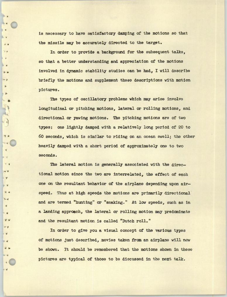
is necessary to have satisfactory damping of the motions so that
the missile may be accurately directed to the target.
In order to provide a background for the subsequent talks,
so that a better understanding and appreciation of the motions
involved in dynamic stability studies can be had, I will describe
briefly the motions and supplement these descriptions with motion
pictures.
The types of oscillatory probleillS which may arise involve
longitudinal or pitching motions, lateral or rolling motions, and
directional or yawing motions. The pitching motions are of two
types: one lightly damped with a relatively long period of 20 to
60 seconds, which is sim~.lar to riding on an ocean swell; the other
heavily damped with a short period of approximately one to two
seconds.
The lateral motion is generally associated with the direc
tional motion since the two are interrelated, the effect of each
one on the resultant behavior of the airplane depending upon air
speed. Thus at high speeds the motions are primarily directional
and are termed "hunting" or "snaking." At low speeds, such as in
a landing approci.ch, the lateral or rolling motion may predominate
and the resultant motion is called "Dutch roll."
In order to give you a visual concept of the various types
of motions just described, movies taken from an airplane will now
be shown. It should be remembered that the motions shown in these
pictures are typical of those to be discussed in the next talk.

• •
In these movies you are getting a pilot's eye view, looking •
forward through the windshield over the nose of the airplane •
I - Longitudinal motions•
(a) Long period ~ The motion shown here woulu be objec
tionable. Ordinarily this motion is not as severe
.. and can be easily controlled by the pilot •
(b) Short period ~ This shows a well-damped motion
typical of most airplanes. - This more persistent
motion may occur on an airplane with low damping,
such as a tailless type.
II - Lateral-directional motions
(a) Snaking - This type of motion would make aiming at
a target more difficult.
(b) Dutch roll - This behavior would add considerably to
the difficulty of flying under instrument conditions.
- This shows difficulty in making a landing with an
airplane with Dutch roll tendencies such as a
swept-wing type. The pilot is attempting to maintain
as smooth an approach as possible.
You have been shown some examples of undesirable dynamic
stability. The next speaker, Mr. , will discuss what
the NACA is doing to improve dynamic-stability characteristics.
Mr.

DYNAMIC STABILITY
by
> • FLIGHT RESEARCH LABORATORY NO. l
SPEECH II
Mr. ------has shown us some examples of poor dynamic - >
stability. The fact that these instabilities exist on recent
designs indicates that changes in aircraft, such as increased
wing sweepback, increased airspeed and increased flight altitude, ' - o-
have raised new problems relative to stability and control. I.et
us inspect the procedure with which the aircraft designer studies
the dynamic stability of his design, and then we shall review how
the NACA is working to improve these characteristics.
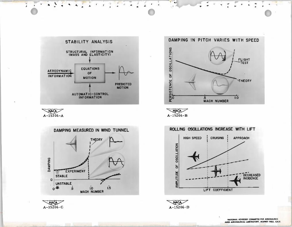
This functional diagram represents the procedure of dynamic-
stability study in a simplified form. The designer wishes to pre-
diet how the motion of his airplane varies with time as shown here.
This box represents the "equations of motion" of the aircraft and
their manipulation into a more convenient form. In order to pre-
diet this motion the designer must insert into the computational
machinery the various types of information represented by these
arrows; for instance, this structural information would be supplied
by the designer from the characteristics of his structure. Now,
while the NACA is engaged to a limlted extent in obtaining all ..
this information, an important portion of our work is obtaining
this aerodynamic information and presenting it in a form for con
venient use by designers.

••
..
Recent study of the three instabilities presented by
Mr. ~~~~~- are examples of NACA work directly adding to the
available aerodynamic information •.. I.et us first consider the reduction of dam.ping in pitch tha~
has been troublesome in several recent designs at transonic
speeds. In flight tests of a tailless research airplane, prolonged
oscillations in pitch unexpectedly occurred when the airplane was
disturbed from steady flight at high speed. This is a plot of
persistence of pitching oscillations versus Mach number. Stability
predictions had indicated a variation in persistence as shown here,
but actual flight tests displayed the sudden increase shmm by
this curve.
To clarify the factors which were causing this reduction in
dam.ping, wind-tunnel measurements were made over a wide range of
subsonic and supersonic speeds. The results of one of these
investigations are shown on this chart. Here rate of damping of
pitching oscillations is plotted versus Mach number.
The subsonic tests were made in the .A.zoos 12-foot wind tunnel.
While theory shows a continued increase in stability, wind-tunnel
tests again show this rapid reduction in stability that was noted
in flight tests.
It is to be emphasized that this divergence occurs in the
transonic range. This gap in our available information is being
filled by flight-research and rocket-model tests. Departure
from predict:ion is not anticipated in flights in the completely
supersonic region, for agreement between theory and wind-tunnel
• '1
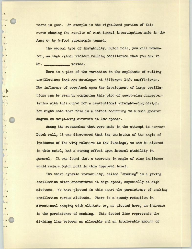
tests is good . An example is the right-hand portion of this
curve showing the results of wind-tunnel investigation made in the ..
Ames 6- by 6--foot supersonic tunnel.
The second type of instability, Dutch roll, you will remem
ber, as that rather violent rolling oscillation that you saw in
Mr. ~~~----~movies • . . Here is a plot of the variation in the amplitude of rolling
oscillations that are developed at different lift coefficients.
The influence of sweepback upon the development of large oscilla
tions can be seen by comparing this plot of swept-wing character
istics with this curve for a conventional straight-wing design.
You might note that this is a defect occurri ng to a much greater
degree on swept-wing aircraft at low speeds.
Among the researches that were made in the att empt to correct
Dutch roll, it was discovered that the variation of the angle of
incidence of the wing relative to the fuselage, as can be altered
in this model, had a strong effect upon lateral stability in
general . It was found that a decrease in angle of wing incidence
would reduce Dutch roll in this improved level .
The third dynamic instability, called "snaking" is a yawing
oscillation often encountered at high speed, especially at high
altitude . We have plotted in this chart the persistence of snaking
oscillation versus altitude . There is a steady reduction in 'f
directional damping with altitude or, as plotted here, an increase
in the persistence of snaking. This dotted line represents the
.. dividing line between an allowable and an intolerable amount of
> •
T r
oscillat j_on .
While the usual straight wing design has these satisfactory
characteristics, the swept-wing airplane represented by this curve
was not acceptable with the persistence inherent in the design.
While the instability can often be explained in terms of sloshing
of fuel, rough air, and loss in damping at high Ma.ch numbers, the
designers, in this case, looked to the low effectiveness of the
ve~tical tail as the source of the difficulty. The vertical tail
is the main contributor to the directional stability and a larger
size would have solved the problem. The same result was attained
by increasing the effective size of the tail by introducing an
automatic control that moved the rudder in such a fashion as to
resist any yawing motion, just as though the tail itself were
larger. Thus, the designers effectively increased the directional
stability and moved the persistence of the oscillations to this
satisfactory level.
At this time the NACA is engaged in several projects study
ing this subject and is now flying an airplane upon which it is
possible to vary several stability characteristics at once.
This airplane will be part of the subject of furtter discus
sion by Mr·~~~~~~~' our next speaker .
Mr-~~~~~~~

DYNAMIC STABILITY
by
FLIGET RESEARCH LABORATORY NO. 1
.. SPEECH III
Perhaps some of you have wondered where the previous speaker . ,
obtained the information that appeared on the charts regarding the
motlons that were satisfactory and those which were not satisfac
tory. After all., when a designer goes through the process of com
puting the motions of his projected airplane, the results are
nothing more than a lot of wavy lines on a piece of paper. How)
can the designer interpret these motions? How would the pilot
react to the motions ?
The NACA has under way an extensive program which is pointed
toward helping the designer to interpret the motions of hi s air
plane once those motions are predicted. T •
One project in this general program which might be of interest
to you is being carried on here at the Ames Laboratory. A conven
tional, propeller-driven, fighter airplane has been fitted with
some special servo equipment which makes it possible to subject
pilots to numerous combinations of flight motions which are typical
of future airplanes.
For instance, this is a mod.el of the test airplane. Now, by
turning a knob the pilot can effectively do this to the airplane.
(Demonstrate.) He can effectively increase the dihedral, or he
can (demonstrate) decrease the dihedral. Also, by making other

• >
)
- 'I
adjustments, the pilot can effectively increase the size of the
vertical tail (demonstrate), or he can decrease the size of the
tail (demonstrate). Note that I use the word "effective" here.
The equipment does not actually change the shape of the airplane,
it merely moves the rudder and the ailerons in such a manner that
the airplane acts as though these changes in shape had been made •
These effective changes naturally change the dynamic character
istics of the airplane radically. By increasing the effective
dihedral the pilot can cause the test airplane to assume the
handling characteristics of an airplane like this in a landing
approach; or, by making other adjustments, he can effectively
fly an airplane like this at supersonic speed. Thus, the equip
ment affords us a. preview of the pilot's reactions to motions we
expect from future airplanes.
To date several Air Force and Navy pilots have flown the test
airplane and have been exposed to the wide range of characteristics
obtainable with the equipment, and an analysis of their opinions
has indicated that the rolling and yawing oscillations of fighter
airplanes should be limited in a manner similar to that shown in
this figure. Here we have the persistence of the oscillations
pl.otted against the amplitude of the rolling motion. This line
represents the boundary between satisfactory combinations of
these two quantities and unsatisfactory combinations. It has been
found that if the airplane doesn't roll much the pilots require
relatively little damping - that is, they will accept fairly long
persistence of th~ oscillations. But if the airplane rolls a lot

• •
the pilots require that the oscillations die out rapidly. These
little insets on the figure show the nature of the motion. In this
area the persistence of the oscillations is long; they do not damp" .
out r 3adily. In this area the amplitude of the rolling motions i s
large (demonstrate). Here are the desirable characteristics; the
persistence is shore and the rolling motion is small.
let's take a look at some movies which show how these motions
appear to the pilot (slide). First, let us examine a good airplane
one whose characteristics fall in this general area on the figure.
(Movies) We are looking forward here through the gunsight. The
sighting point is on the target. Now the pilot abruptly kicks the
rudder pedal and returns it to neutral. We see how the sighting
point returns. (Slide) Now let's see how the oscillations appear
.., .. to the pilot if their characteristics fall across the boundary in
this direction - - that is, if the oscillations persist longer .
(Movies) Here again the sighting point is on the target; the pilot
kicks the rudder and returns it, and we see how the oscillations
fail to damp out quickly_. (Slide) Now let•s see how the oscilla
tions would appear if their characteristics were to fall too far
out in this direction. (Movies) The sighting point is on the tar.. get; the pilot kicks and returns the rudder, and we see that the
oscillations are fairly well damped, but the airplane rolls in an
... < awful fashion • .. . (Lights on, screen slid back, chart still showing.)
/' .. It is from tests of this nature that boundaries such as this
are established to help the designers to interpret the predicted
motions of their projected airplanes.

Another useful project in this over-all program of research
on flying qualities is going on at the Langley laboratory. They
are ma.king use of a device called a yaw chair, which is shown here.
The chair is free to oscillate in yaw much as an airplane oscillates
in yaw. We see that the chair is dynamically stable as it is now
adjusted - - that is, the oscillations become successively smaller
after we d:i.sturb it - - and we see that the pilot has no trouble
brir..ging the chair under control. Now, if we turn on this hydraulic
device, we see that the chair becomes unstable - - the oscillations
build up after a disturbance - - and we see that the pilot finds
it difficult to bring the chair under control. Now by ma.king
adjustments to the hydraulic device the degree of instability
can be changed, a.nd by changing the stiffness of the restoring
springs the period can be varied - that is, the oscillations can
be slowed down, which means a longer period, or they can be speeded
up, which means a shorter period.
This next figure shows some results of an investigation using
this device to determine just how unstable the chair could be
made before it became completely uncontrollable for the pilots .
We have here the degree of instability plotted against the period
of the oscillations. This curve represents the boundary between
controllable conditions and uncontrollable conditions. It is seen
that as the period was reduced, the degree of instability which
could be controlled gradually fell off until a critical value of
,. the pE,1riod was reached, below which no instabil:l.ty at all could be
controlled . On the previous demonstration the chair was adjusted

. '
l .,
.. '
so its characteristics fell about here on the chart. With these
heavier springs, the period has been reduced. And, with the
hydraulic device in operation, the pilot finds it impossible to
bring the chair under control.
To illustre.te the importance of keeping the yawing oscillations
well damped as the speed is increased, a typical high-speed
airpl!.ne of today has a natural period about here when traveling
at a speed of 500 mph. Now if we were to fly that same airplane
at 1500 mph we would expect the natural period to be reduced to
about here - - well into the region where the airplane would be
completely uncontrollable if any instability at all existed.
It has been shown at this stage of your inspection that, as
the performance of aircraft increases, dynamic stability problems
are becoming more and more serious. It has been possible to give
here only a brief glimpse of the extensive program the NACA is
following in attempting to aid aircraft designers in all phases of
the dynamic-stability problem.
Thank you.
~ .( ', -4 ~ ... .. • • ~ ~
'\
" \
• • ~
twti'INGWUSUAEDIHW1~D TIJJl.,E L
•..:on ,..,__
-1 ! ,.{ ;\/\
r .... ~...[~.IOl[~T l·--"' ,¥,,...-.-·aa.c '
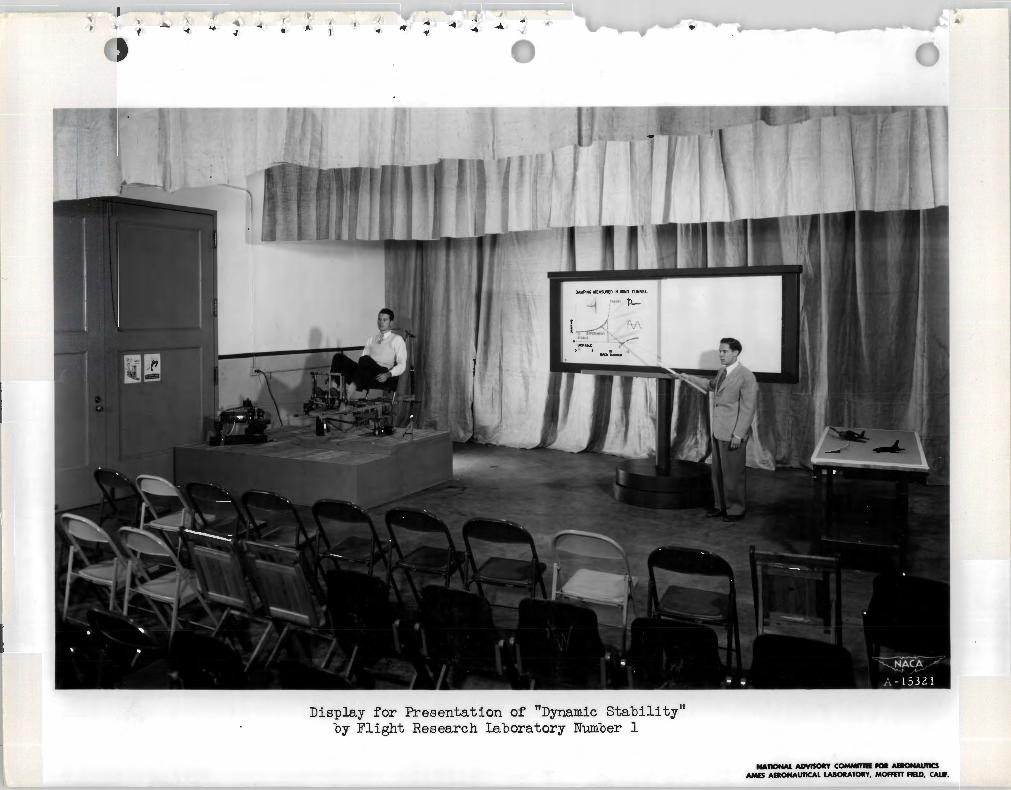
Display for Presentation of "Dynamic Stability11
by Flight Research laboratory Number 1
-110NAI. ADYISOllT COMWnll fOll AHONAU11CS AMES ADONAUTICAL LUOllATOllY, MOffm -D. CAL•.
._, ~\. ... .J ~
~ ~ .. ... ,j._• " >- •A
STABILITY ANALYSIS
STRUCTURAL INFORMATION <MASS AND ELASTICITY>
t EQUATIONS
AERODYNAMIC OF prINFORMATION
MOTION
PREDICTEDt MOTION
AUTOMATIC-CONTROL INFORMATION
~ A-15206-A
DAMPING MEASURED IN WIND TUNNEL
THEORY I I I I
...\ ,-, Z A I
--t"'""":."-' ' 0::(!)~I ,_, ' · ~ I <( . I
o EXPERIMENT :
STABLE : 0 1 I ,,;'
UNSTABLE ,' o ...J. .5 1.0 1.5
MACH NUMBER
~
£ .. ~ ..... ~
> ~
DAMPING IN PITCH VARIES WITH SPEED
z I
I
Ill
0 !\;\; .I
<( : FLIGHT...J ...J 1 -----TEST
I 0 I 0 Ill I _..../LL 0 .~ ~ I \i ~1 ' THEORY
~o . ' j5 MACH NUMBER .
~ · 10
~ A-15206-B
ROLLING OSCILLATIONS INCREASE WITH LIFT
HIGH SPEED CRUISING APPROACH
z 0
~ ...J ...J (3 Ill 0
LL 0
w .........., : --· gI I . - - .. - - - - DECREASED ~ ------- ,- --- !~ INCIOENCE
<( _ I ~-------LIFT COEFFICIENT
~~ A-15206-C A-15206-D
NATIONAL ADVISORY COMMITTEE FOR AERONAUTICS AMES AERONAUTICAL LABORATORY, MOFFETT FIELD, CALIF.

~ ~ .._ ,J -<
..(J.. •. .. -< .. -< .. >· •
DAMPING IN YAW LESS AT ALTITUDE YAWING AND ROLLING OSCILLATIONS
(!)
z :.:: ~ <t z en en
wzIJ... uo0 z-w w~ (.) I- _J
z ~_J
w enc:; ~ t o:: en en ~o en IJ...0:: SATISFACTORY0w a...
0 25.000 ALTITUDE. FT AMPLITUDE OF ROLLING
~ ~ A-15206-E A-15206-F
PILOTS' ABILITY TO CONTROL UNSTABLE OSCILLATIONS
>1_J
aJ <t ten z
CONTRO~LABLE IJ... 0
PERIOD OF OSCILLATION
~
A- 15206-G
NATIONAL ADVISORY COMMITIEE FOR AERONAUTICS AMES AERONAUTICAL LABORATORY, MOFFETT FIELD, CALIF.