dynamic response of liquid tanks during near fault …
TRANSCRIPT

Dynamic Response of Liquid Tanks
during Near Fault Earthquakes R Sreekala, A Meher Prasad Indian Institute of Technology, Madras K Muthumani, N Lakshmanan, Nagesh R Iyer CSIR-SERC, CSIR-Structural Engineering Research Centre, Chennai 600 113, India
SUMMARY: Dynamic behavior of liquid storage tanks during strong ground motion requires lot of research attention and sloshing is one of the major concerns in the design of liquid storage tanks. Simulated experimental investigations using 3D shake tables are rare in this field and the non-linear dynamic behavior of the structure is of interest, especially during near fault earthquakes. The paper presents an experimental investigation under simulated conditions on a fixed base rectangular container with water. The tank has been designed to suit experimental requirements and the dimensions were selected to fit the structure in 2m- tri axial shaking table. The behavior of the system is identified during dynamic loading using harmonic excitation and simulated earthquake studies were carried out further on the 3D shaking table. Higher dynamic pressures on the walls and increased dynamic loads on the tank due to the pulse characteristics of ground motion have been verified during the investigation. Computational modeling has been carried out on the experiments conducted and the results are discussed. Keywords: Dynamic behaviour of liquid tanks, Near fault earthquakes, Sloshing, Computational modelling 1. INTRODUCTION Liquid storage tanks belong to those classes of structures in which their value to society far exceeds the economic worth of both the tanks and their contents. During the past earthquakes, liquid storage tanks have suffered varying degree of damages. The hazardous effect of liquid sloshing and the extensive damage sustained by liquid-filled tanks were evident in past seismic events such as the 1964 Alaska, the 1964 Niigata, the 1968 Tokachi-Oki, the 1979 Imperial Valley, the 1983 Coalinga, and more recently, the 1989 Loma Prieta, the 1992 Landers and the 1994 Northridge earthquakes. Documented case histories of actual storage tanks in strong earthquakes are limited. But there are numerous reports on loss of contents of the tank, fires, and rupture of pipeline attachments to tank walls rather than the failure of the tank walls itself. Due to the acquisition of new knowledge on strong ground motions, codal provisions for ensuring the safety of liquid tanks for strong earthquake motions are in the evolving stages around the world. A foremost task in evaluating the seismic safety of a liquid container is to evaluate the hydrodynamic forces of the sloshing liquid exerted on the structure. The wave amplitude and hydrodynamic pressure distribution on tank walls are of important criteria to be examined during seismic excitation of liquid tanks. Near source records are special and their effects on various structures are of research interest in recent years. They are known for their pulse characteristics due to directivity effects and are particularly damaging for structures. Asymmetric high amplitude velocity and displacement pulses observed in fault normal near field earthquakes produce large residual displacements and normally push the structure into the non linear range. Rupture directivity and tectonic fling are the two conditions that lead to large long period pulses of ground motion. Directivity effects are the main causes of velocity pulses even though there are other causes like site location, fault geometry and slip. If a site is located near an asperity in the fault rupture, the waves caused by that asperity can produce a pulse at the site. Near-field events will produce body and surface waves that cause changes in the direction of the
surface response at considerably fast rates. This fact will translate into rotations at the soil or lead to spatial variability in the ground motions that are naturally transmitted into engineering structures. Detailed studies of the wave incoherence effect on the response of building structures were reported in Literature (Veletsos and Prasad, 1989). Constructive interference of seismic waves passing through a complicated earth structure such as the edge of a geologic basin can also give rise to velocity pulses. A more detailed description of this phenomenon is given in literature (Somerville et al., 1997). Acceleration pulses can also occur at sites located at large distance from the epicenter due to path and local soil effects. It is recorded (Housner and Hudson, 1958) that the March 18, 1957 Port Hueneme earthquake consisted essentially of a single pulse. Since energy was contained in one pulse, the damage caused by this earthquake was unusual for a moderate earthquake. Most of the predominant periods of great and large earthquakes vary between 2s and 8s and the predominant period of a pulse tends to increase with magnitude. Even a small to moderate magnitude near fault earthquake with characteristic features can pose greater earthquake demand if the period of the structure is nearer to the pulse period. The first recorded data in the United States that contained damaging acceleration pulses was the record obtained at Pacoima Dam during the San Fernando, California earthquake of February 1971. Even though there exists variety of methods and parameters to characterize the damage potential of strong earthquakes there exists a huge gap in identifying a real unfavorable ground motion indicator in the time or frequency domain which fits into the various classes of structures following the inelastic analysis. The choice of selection of ground motion can be simple thresholds on Peak Ground Acceleration (PGA) or Peak Ground Velocity (PGV) or complicated spectrum based criterion. The Arias Intensity (IA), which determines the intensity of shaking by measuring the acceleration of transient seismic waves, has been used as a reliable parameter to describe earthquake shaking (Arias, 1996). It is defined as the time-integral of the square of the ground acceleration which is an intensity measure. Apart from this there exists other methods based on wavelet analysis and methods based on entropy principle to identify resonant accelerograms (Abbas and Manohar, 2002). Some recent tools to investigate the pulse like records are applied by researchers for well known pulse like ground motion records and recent earthquakes (Sreekala et al., 2011).
Sloshing is characterized by the oscillation of unrestrained free surface of the liquid in a partially filled container due to external excitation and is one of the major concerns in the design of liquid storage tanks undergoing ground excitation. Most of the studies on dynamic behavior of fluid containers are concerned with cylindrical tanks than rectangular ones. In the design codes, mechanical analogs of tank-fluid system are commonly used to obtain the sloshing frequency, hydrodynamic pressure and design seismic forces. Damages to tanks in the Chilean earthquake of 1960 led to the development of simple mechanical analogue of tank-liquid system by Housner (1963). He developed a simplified method where an effective fluid mass accelerates with the container while an additional effective fluid mass undergoes resonant motions at the lowest sloshing frequency. He thus split the forces into two components: an impulsive force with a short period and longer convective force that gives the sloshing effect. This simple mechanical analogue of tank-liquid system forms the basis for evaluating hydrodynamic pressure in most of the design codes across the globe. Subsequently, the effect of shell flexibility on the hydrodynamic pressure and fluid-structure interaction is included (Haroun et al., 1984, and Velestos et al., 1992 ). There exists two methods of analysis for design purposes: 1) Haroun and Housner Procedure, and 2) Veletsos and Yang Procedure. Both consider horizontal component of ground motion and convective effects are found to be unaffected by the flexibility of tank wall. Draft Indian code provisions has been formulated using Housner’s mechanical model (Jaiswal et al., 2004). The analytical studies by Veletsos and Tang (1986) on cylindrical tanks throw light on the impact of vertical component of ground shaking. Clough (1977) brought out one of the earlier documents on the design methods for broad cylindrical tanks. As far as the documented evidence of tank damages, Manos and Clough (1985) describes the tank damages due to 1983 Coalinga earthquake. Hatayama (2008) described severe earthquake-induced sloshing damage to seven large oil storage tanks with floating roof structures as the consequence of the 2003 Tokachi-oki earthquake in northern Japan, which generated large amplitude long-period (4-8 sec) ground motions. The highest natural sloshing
period in the tanks suffering severe damage ranged from 5 to 12 s. The damage occurred in terms of roof sinking and fire.
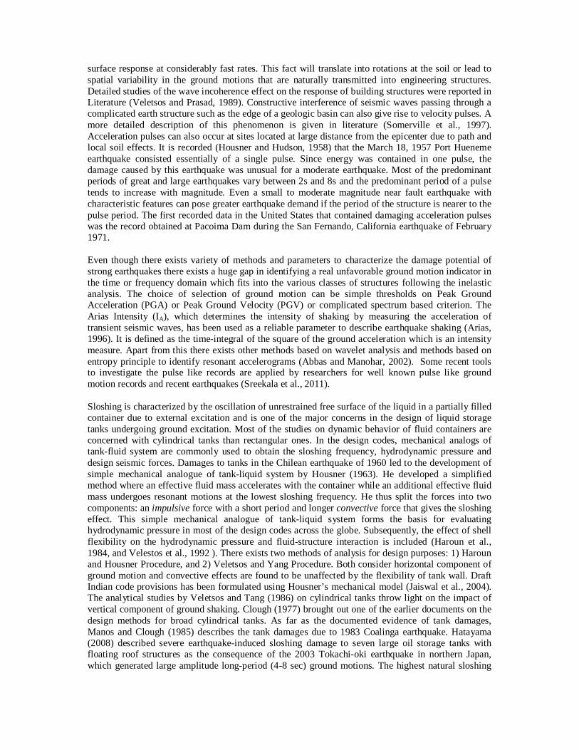
2. EXPERIMENTAL INVESTIGATION The experiments were conducted in a tri-axial shaking table of 5 tonne capacity in ASTaR Lab, CSIR -SERC. A simple experimental set up was designed and fabricated to conduct experiments for measuring the dynamic parameters during excitation. The tank has been designed to suit the experimental objectives and the dimensions were selected to fit the structure in the 2m-Shaking Table. The plan dimension of the tank is 1.2m 1.0m with a height of 1.0m. The base of the tank and the frame was fabricated in steel and an arrangement is made to fix the structure on the shaking table. The walls were made of Perspex sheets (Acrylic based-12 mm thick) in order to view the sloshing phenomena experimentally and for image capturing purposes. A sloshing probe, which consists of non-contact displacement sensors, has been developed to record the free surface wave height. Two non-contact sensors, which capture the data along the mid and corner width of the tank respectively, were used to collect the wave height information. The whole arrangement consisting of wave height and acceleration measurement on two locations was mounted on a movable wooden frame. The photograph of the test set up is shown in Fig. 2.1. The device recorded the free surface wave heights and simultaneously acceleration of the liquid inside the tank. The test data were collected at twelve other locations along the length of the tank during sweep sine and earthquake excitations. Pressure sensors were calibrated and installed at three locations along the height of the tank at 0.12m, 0.33m, and 0.53m from the tank bottom, respectively. The sensors were used in conjunction with a signal processing unit where it collects the data in terms of voltage signal between 0 V and 10 V. The electrical signals are continuously recorded with the help of 16-channel data acquisition system.
Figure 2. 1. The experimental set up with various sensors – The non-contact slosh height instrumentation The liquid filled tank up to a height of 0.64m is mounted on the shake table and sweep sine as well as harmonic tests were carried out. A sweep sine test in the frequency range 0.25 to 5 Hz is conducted to identify the dynamic behavior of the system for harmonic excitation at the sloshing frequency. Simulated earthquake studies were carried out further on the 3D shaking table. Actual Pacoima earthquake (horizontal component) record was selected and scaled down for the experimental tank for which the sloshing frequency matched with the pulse period of the input time history (Fig. 2.2). Fig. 2.3 shows the target and achieved spectrum for the near fault time history for simulation purposes. Tests were conducted for two acceleration levels, namely 0.1g and 0.2g, by scaling down the actual earthquake records. Experiments were conducted on the tri-axial shaking table system and

the quantities of interest such as hydrodynamic pressure on the wall, accelerations inside the liquid and outside tank wall, as well as sloshing height of the liquid have been examined.
Figure 2.2. Typical time history used for the study- Acceleration level scaled to 0.1g
0 1 2 3 4
0.0
0.5
1.0
1.5
2.0
2.5
3.0
3.5
Spec
tral A
ccel
erat
ion
Time Period, Seconds
Target-Y Axis-Near Fault Achieved-Y Axis-Near fault
Figure 2.3. Spectral plot of typical time history generated on shake table- Acceleration level scaled to 0.1g 2.1. Natural Modes and Sloshing Wave height The condition of liquid incompressibility which the velocity potential Φ need to satisfy everywhere in the liquid volume is given by the following differential equation,
(2.1.1)
The complete solution of the Eqn. 2.1.1 should satisfy the boundary conditions at the free surface and at the tank walls, and the eigen-functions can be obtained for various motions of the tank. The roots of these eigen-functions represent the natural frequencies of the sloshing liquid. The solution ωn for the natural frequency can be expressed as
(2.1.2)

where the subscript n indicates the mode number for a rectangular tank of width a containing liquid of height h. The anti-symmetric modes are capable of producing lateral forces or torques and the slosh wave shape can be expressed in the Cartesian coordinate system as
. (2.1.3)
Where A represents, generalized time dependent co ordinate satisfying the free surface boundary conditions. The natural frequencies of liquid in the tank were obtained theoretically using Housner’s expression and are compared with the experimental results (Table 2.1). Table 2.1. Frequency of first three modes from theoretical and experimental investigation
Mode Frequency (Theoretical), Hz Frequency (Experimental), Hz
Mode 1 (Anti-symmetric) 0.78 0.75 Mode 2 (Anti-symmetric) 1.46 1.48 Mode 3 (Anti-symmetric ) 2.12 2.25
Figure 2.4. FFT of the response signal with the first mode wave profile shown in the insert
The sloshing wave height was also found out using this study and the maximum wave height was found to be 61mm. Fig. 2.4 shows the FFT’s of the response signal during lateral harmonic excitation which clearly identifies the natural frequencies. Photograph showing first mode is given in the insert. The values shown in Table 2.1 is very good agreement between experimental and theoretical values. Similar observation was found for the sloshing height also. The maximum sloshing height of 61 mm, observed during the experiment was in agreement with the theoretically found value of 58 mm. In the case of pressure, the observed values are differing from the theoretical predictions. Free vibration test on the tank and the acrylic wall shows that the natural frequency of wall, which is far away from the sloshing frequency of the liquid, corresponds to 12.5 Hz at which the tank wall experienced maximum
0
20
40
60
80
100
1200 2 4 6 8 10 12 14
2.25 Hz
1.48 Hz
0.75 Hz
Ampl
itude
0 2 4 6 8 10 12 14
0100200300400
Angl
e(de
g)
Frequency (Hz)
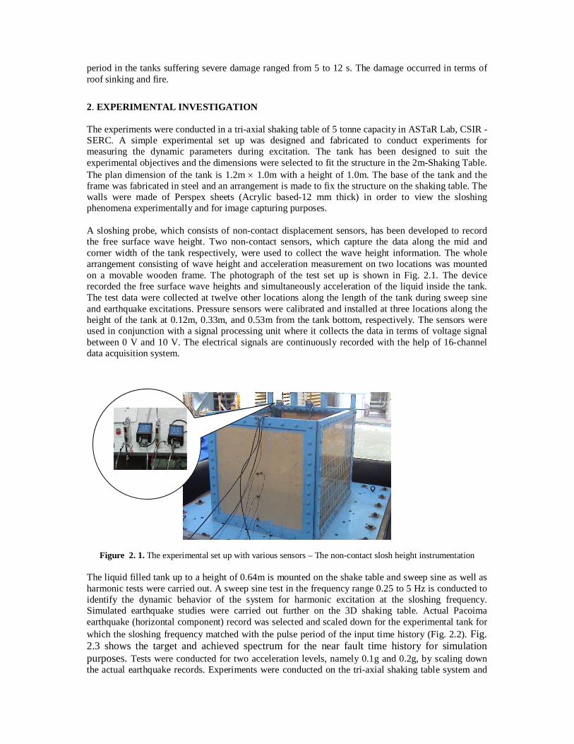
accelerations. The pressure time history traces on the wall during the sweep sine test using the three pressure gauges installed are shown in Fig. 2.5. The peak value of the dynamic pressure observed in this case is 3.75 kPa.
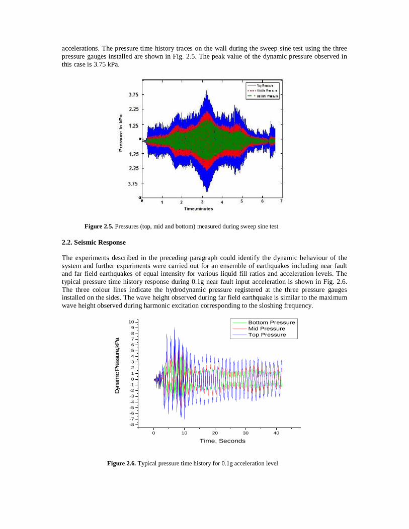
Figure 2.5. Pressures (top, mid and bottom) measured during sweep sine test 2.2. Seismic Response The experiments described in the preceding paragraph could identify the dynamic behaviour of the system and further experiments were carried out for an ensemble of earthquakes including near fault and far field earthquakes of equal intensity for various liquid fill ratios and acceleration levels. The typical pressure time history response during 0.1g near fault input acceleration is shown in Fig. 2.6. The three colour lines indicate the hydrodynamic pressure registered at the three pressure gauges installed on the sides. The wave height observed during far field earthquake is similar to the maximum wave height observed during harmonic excitation corresponding to the sloshing frequency.
0 10 20 30 40
-8-7-6-5-4-3-2-10123456789
10
Dyn
amic
Pre
ssur
e,kP
a
Time, Seconds
Bottom Pressure Mid Pressure Top Pressure
Figure 2.6. Typical pressure time history for 0.1g acceleration level

Figure 2.7. Dynamic pressure variation observed during the study
Large amplitude sloshing and liquid impact on walls were observed during the experiments. Fig. 2.7. clearly shows the nonlinearities emerging out of pulse type seismic ground motions. The selected near field and far field earthquakes were of same peak ground acceleration values. The dynamic pressure observed during far field earthquake is found to be similar to the maximum pressure observed for harmonic excitation. But in the case of near fault earthquakes, the impact pressure increases non-linearly with the increased velocity of the ground motion.
3. COMPUTATIONAL SIMULATION Regarding modeling the fluid flow, studies related to sloshing and multi-modal methods are described elsewhere (eg., Faltinsen and Timokha, 2000). Finite element method for solving the linear floating body hydrodynamic problem is considered by researchers with a hierarchy of boundary damper options for modeling the far field (Krishnankutty and Vendhan, 1995). Here in the present study interface tracking methods are applied to simulate the fluid behavior within the tank. The study models fluid motion with the incompressible Navier-Stokes formulation (Faltinsen and Timokha, 2000) and the 2D model is used to simulate dynamic free surface flow with the help of a moving mesh. This model describes the fluid dynamics with the incompressible Navier-Stokes equations. There are two types of boundaries in the model domain. Three solid walls, that are modeled with slip conditions, and one free boundary (the top boundary). The harmonic excitation in the tank is modeled using VOF (Volume Of Fraction method) and the sloshing heights are in good agreement. The ALE (Arbitrary Lagrangian-Eulerian) technique has been set up using the moving mesh interface to represent the free surface boundary. Surface tension effects are neglected in the model. The deformation of this mesh relative to the initial shape of the domain is computed using Winslow smoothing. Computational fluid dynamics (CFD) method used can be used for any generally shaped tank with any filling depth and can handle any generic excitation. Later on level set methods for the two phases, which represent the interface by a contour of a smooth function with good mass conservation while considering the three dimensional free surface flows, have been implemented. A phase field method has been implemented for the two-phase laminar flow. The simulated model can well determine the sloshing wave heights and the dynamic behavior

including pressures, during the harmonic excitation. The simulation results are shown at various time steps. Fig. 3.1 and Fig. 3.2 show the experimentally observed behavior and the computational modeling of sloshing. As the fluid is pushed to a higher velocity regime, the analytically predicted hydrodynamic pressure on the tank walls needs modification. The hydrodynamic pressures have been underestimated by more than 40% in case of near field earthquakes.
Figure 3.1. Computational simulation of sloshing –Typical snapshot and the observed sloshing height in m for 5 seconds
Figure 3.2. Experimentally observed sloshing –Typical snapshot and the experimentally observed sloshing height in mm for 5 seconds
4. SALIENT OBSERVATIONS Traditionally, the small-amplitude wave theory has been used exclusively in evaluating the seismic performance of liquid-filled containers. As the excitation frequency approaches resonance, the liquid free surface experiences complex motions. It is found from the experiments that the waves follow second order wave theory as evident from the wave profiles. Sinusoidal unidirectional progressive deep-water waves are normally represented by first order linear solution, which is represented by
ζ = ζa sin (휔푡 − 푘푥) (4.1)
where ζa denotes wave amplitude, k = 2π/λ, λ being the wave length, ω = 2π/T, T is period of wave. It is possible to show that second order velocity potential is zero and the second order wave elevation is ζ2 and is given by
ζ2 = ‒ 1/2 ζa2k cos [2(ωt-kx)] . By combining this with the first-order solution ζa sin(휔푡 − 푘푥), we get
ζ = ζa sin(ωt−kx) ‒ 1/2 ζa2k cos[2(ωt−kx)] + O ((ζa/λ)2) (4.2)
Second order theory means that keeping all terms proportional to O((ζa/λ)2) and O(ζa/λ) in a consistent way (Faltinsen and Timokha, 2000). Second order wave interaction causes different frequency effects with energy at the important resonant frequencies, where the first order refers to linear waves. The second order solution given in the Eqn. 4.2. sharpens the wave crests and makes the trough shallower clearly visible during the experiments conducted. The second order wave profile for the wave steepness value, H/λ is found to be 0.049 for the harmonic excitation and reaches up to 0.1 in case of near fault earthquake with input acceleration of 0.2g. Here H denotes the wave height defined as the vertical distance between the trough and the crest. In all the cases the relative error between second order and infinite order is less than 0.8 %. Substantial differences observed in the evolution of hydrodynamic pressures in case of near field earthquakes. It has been observed that top and bottom hydrodynamic pressures are found to be out of phase throughout the tests and this can give rise to cross sectional distortions during the seismic event. Higher dynamic pressures on the walls and increased dynamic loads on the tank due to the pulse characteristics of ground motion have been verified during the investigation. Depending on the ground motion characteristics and the liquid height to characteristic length ratio, the hydrodynamic pressures on the tank walls were found to be increased by a factor of six in case near fault earthquakes from the study.
5. CONCLUSIONS The present study throws light into the dynamic behavior of liquid tanks during seismic excitation, especially strong seismic events. Out of the various parameters, the hydrodynamic pressure variation is found to deviate from the existing theoretical predictions. Impact pressures induced by liquid sloshing can damage the wall structures of the containment system and the highly nonlinear free surface flow increases the torque in ground supported rectangular containers. The higher dynamic pressures are important for the stresses, but its influence on the horizontal force is negligible. The shape of the hydro-dynamic pressure traces closely resemble the input earthquake shape. The peak hydrodynamic pressures observed tend to increase from the base to the crest and this is consistent with the acceleration amplifications. The top and bottom hydrodynamic pressures are out of phase and this phase difference may lead to cross sectional distortions during the seismic event. Normally tank walls are designed for the beam like responses predicted by the analysis procedures and the cross sectional distortions as evident from many of the earthquakes have been attributed to the imperfections in the geometry or fabrication. As the structure is pushed to a higher velocity regime, there is significant increase in the dynamic peak fluid pressure on tank walls and the localized stress amplification need to be accounted in the design of liquid storage tanks. ACKNOWLEDGEMENT The work is associated with the Ph-D dissertation of the first author in and the encouragement given by all the Doctoral Committee members are gratefully acknowledged. The paper is being published with the kind permission of the Director, CSIR-SERC and the authors are grateful for the support rendered by the colleagues of ASTaR Laboratory, CSIR-SERC during the experimental programme. REFERENCES
Abbas, A. M. and Manohar, C.S. (2002). Investigations into critical earthquake load models within deterministic and probabilistic frameworks. Earthquake Engineering and Structural Dynamics 31, 813–832.
Arias, A. (1996). Local directivity of strong ground motion. Proceedings of the Eleventh World Conference on Earthquake Engineering, Paper No. 1240.
Clough, D.P. (1977). Experimental evaluation of seismic design methods for broad cylindrical tanks, University of California CA, Berkeley, Report No UCB/EERC-77/10.
Faltinsen, O.M., Rognebakke, O. F., Lukovsky, I.A. and Timokha A N. (2000). Multidimensional modal
analysis of nonlinear sloshing in a rectangular tank with finite water depth. Journal of Fluid Mechanics
407, 201-234. Haroun, M. A. and Housner, G. W. (1984). Seismic design of liquid storage tanks, Journal of Technical Councils
of ASCE 107: TC1, 191-207. Hatayama, K. (2008). Lessons from the 2003 Tokachi-oki, Japan, earthquake for prediction of long-period
strong ground motions and sloshing damage to oil storage tanks. Journal of Seismology 12, 255-263. Housner, G.W. (1963). The dynamic behavior of water tanks. Bullettin of Seismological Society of America 53:2,
381-387. Housner, G.W. and Hudson, D.E. (1958). The Port Hueneme earthquake of March 18, 1957. Bulletin of
Seismological Society of America 48, 163-168.
Jaiswal, O. R., Rai, D. C. and Jain, S.K. (2004). Codal provisions on design seismic forces for liquid storage tanks: a review, Report No. IITK-GSDMA-EQ-01-V1.0, Indian Institute of Technology Kanpur, Kanpur
Krishnankutty, P. and Vendhan, C.P. (1995). Three-dimensional finite element analysis of the diffraction-radiation problem of hydrodynamically compact structures, Marine Structures 8:5, 525-542.
Manos, G.C. and Clough, R.W. (1985). Tank damage during the May 1983 Coalinga earthquake. Earthquake
Engineering and Structural Dynamics 13, 449-466. Somerville, P. G., Smith, N. F., Graves, R. W. and Abrahamson, N. A. (1997). Modification of empirical strong
ground motion attenuation relations to include the amplitude and duration effects of rupture directivity. Seismological Research Letters 68:1, 199–222.
Sreekala, R., Muthumani, K., Prasad, A. M. and Nagesh, R, Iyer. (2011). Pulse like ground motions-Quantification on damage severity. SmiRT-21, Book of Abstracts Vol.1, 459.
Veletsos, A.S. and Prasad, A. M. (1989). Seismic interaction of structures and soils: stochastic approach. ASCE
Journal Structural Engineering Division 115:4, 935-956. Veletsos, A.S., Tang,Y. and Tang, H.T. (1992). Dynamic response of flexibly supported liquid-storage tanks.
ASCE Journal of Structural Engineering 118:1, 264-283. Veletsos, A.S. and Tang, Y. (1986). Dynamics of vertically excited liquid storage tanks. ASCE Journal of
Structural Engineering 112:6, 1228-1246. .