seismic analysis of liquid storage tanks _ k meskouris
TRANSCRIPT

2nd INQUA-IGCP-567 International Workshop on Active Tectonics, Earthquake Geology, Archaeology and Engineering, Corinth, Greece (2011)
INQUA PALEOSEISMOLOGY
AND ACTIVE TECTONICS
EARTHQUAKE ARCHAEOLOGY
136
SEISMIC ANALYSIS OF LIQUID STORAGE TANKS
Konstantin Meskouris, Britta Holtschoppen, Christoph Butenweg, Julia Rosin (1)
(1) Chair of Structural Statics and Dynamics, Mies-van-der-Rohe Strasse 1, 52074 Aachen, GERMANY. Email: [email protected]
Abstract (Tank design for seismic loading): In the event of strong earthquakes, it is important that the structural integrity of tanks containing liquids is maintained in order to not jeopardize the population's supply with essential goods. The continuous operation of tanks after strong earthquakes requires safe and effective design rules. The overall seismic behaviour of tanks is, however, quite complex, since the dynamic interaction effects between tank wall and liquid must be considered. The interaction can be simplified with the concept of generalized single-degree-of-systems representing the convective, rigid impulsive and flexible impulsive vibration modes of tank and liquid. This concept is well accepted for anchored tanks with a fix connection to a rigid foundation. This paper presents the state of the art of tank design with special focus on the practicability of the available design rules. Analytical and numerical calculation approaches are compared on the example of a typical tank geometry, taken the relevant interaction effects into account. Key words: liquid filled tank, seismic design, impulsive vibration mode, critical facilities INTRODUCTION Recent earthquake events showed that heavy seismic damages of tanks may lead to environmental hazards, fire following earthquakes and temporary loss of essential facilities. The vibration of liquid filled tanks subject to seismic loading depends on the inertia of the liquid and on the interaction effects between the liquid and the tank shell. Different calculation methods are available for describing the vibration behaviour and the earthquake loads. These methods are either quite simple (Housner, 1963) or very accurate but complex (Fischer et al., 1991). Therefore a well comprehensive and feasible method is needed, that provides realistic results for the seismic behaviour of tanks with an acceptable computing time. The following considerations apply to cylindrical, anchored tanks with a fix connection to a rigid foundation. SEISMICALLY INDUCED LOAD COMPONENTS OF LIQUID FILLED TANKS The seismic loads acting on wall and bottom of cylindrical tanks (Figure 1) can be divided into the following components (Meskouris et al., 2010): - the convective load component; the fluid
vibration in the rigid tank (sloshing), - the impulsive rigid load component; caused by
the inertia of the liquid, if the rigid tank moves together with the foundation,
- the impulsive flexible load component; representing the combined vibration of the flexibile tank shell (e.g. steel tanks) with the liquid.
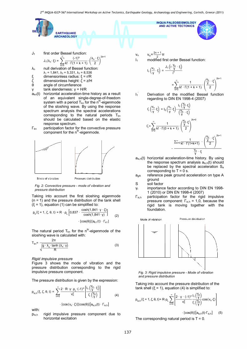
Convective pressure Figure 2 shows the mode of vibration and the pressure distribution corresponding to the convective pressure component. The pressure distribution is defined as:
pk(ξ, ζ, θ, t) =2∙R∙ρL
(λn2-1)
J1(λn ∙ ξ)
J1(λn)cosh(λn∙ γ ∙ ζ)
cosh(λn∙ γ)
∞
n=1
(1)
⋅ [cos(θ)] [akn(t) ∙ Γkn] with pk convective pressure component due to
horizontal excitation n summation index; number of considered
sloshing modes (here: n = 1) R inner tank radius ρL liquid density
Fig. 1: Cylindrical tank
2nd INQUA-IGCP-567 International Workshop on Active Tectonics, Earthquake Geology, Archaeology and Engineering, Corinth, Greece (2011)
INQUA PALEOSEISMOLOGY
AND ACTIVE TECTONICS
EARTHQUAKE ARCHAEOLOGY
137
J1 first order Bessel function:
J1(λn∙ ξ) = (-1)k
k! ∙ Γ(1 + k + 1)∙
λn ∙ ξ2
2k+1∞
k=0
λn null derivation of Bessel function: λ1 = 1,841, λ2 = 5,331, λ3 = 8,536
ξ dimensionless radius: ξ = r/R ζ dimensionless height: ζ = z/H θ angle of circumference γ tank slenderness: γ = H/R akn(t) horizontal acceleration-time history as a result
of an equivalent single-degree-of-freedom system with a period Tkn for the nth-eigenmode of the sloshing wave. By using the response spectrum analysis the spectral accelerations corresponding to the natural periods Tkn should be calculated based on the elastic response spectrum.
Γkn participation factor for the convective pressure component for the nth-eigenmode.
Taking into account the first sloshing eigenmode (n = 1) and the pressure distribution of the tank shell (ξ = 1), equation (1) can be simplified to:
pk(ξ = 1, ζ, θ, t) = R ∙ ρL 0,837 ∙ cosh(1,841∙ γ ∙ ζ)
cosh(1,841∙ γ)
(2)
⋅ [cos(θ)][ak1(t) ∙ Γk1] The natural period Tkn for the nth-eigenmode of the sloshing wave is calculated with:
Tkn= 2π
g ∙ λn∙ tanh (λn∙ γ)R
(3)
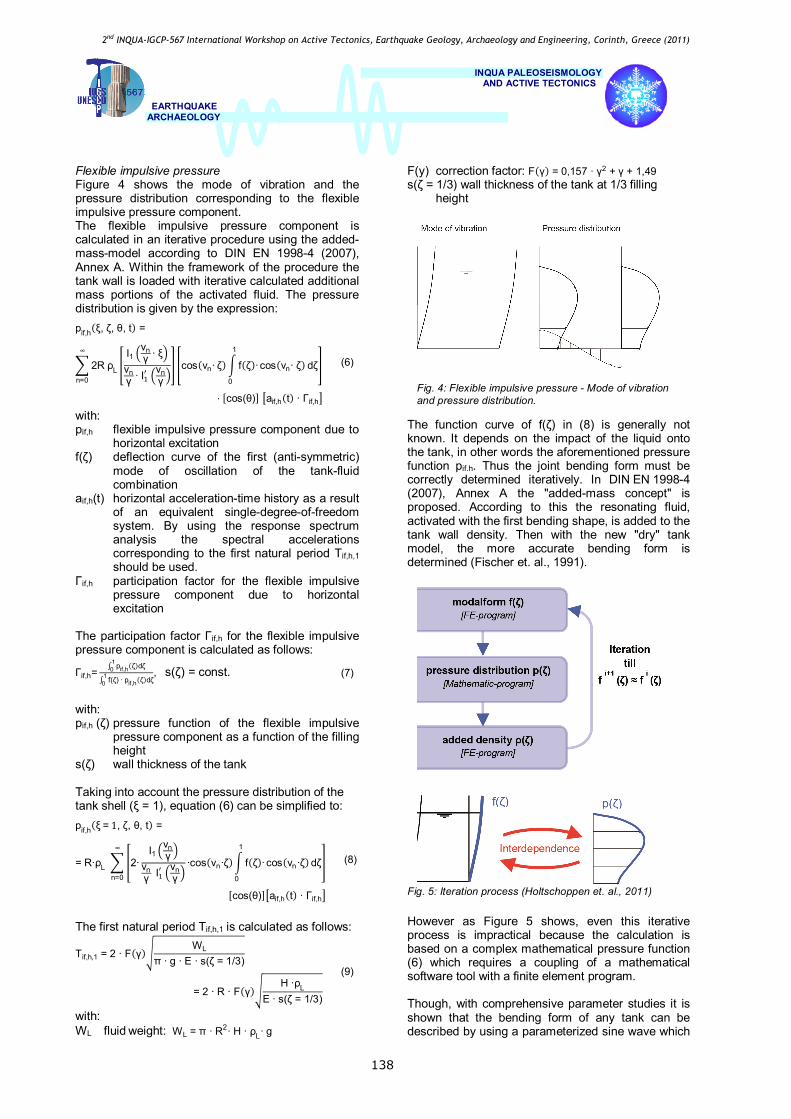
Rigid impulsive pressure Figure 3 shows the mode of vibration and the pressure distribution corresponding to the rigid impulsive pressure component. The pressure distribution is given by the expression:
pis,h(ξ, ζ, θ, t) = 2 ∙ R∙ γ∙ ρL∙(-1)n
νn2
I1νnγ ∙ ξ
I νnγ
∞
n=0
(4)
⋅ [cos(νn∙ ζ)][cos(θ)] ais,h(t) ∙ Γis,h
with: pis,h rigid impulsive pressure component due to
horizontal excitation
νn νn= 2n + 12
π I1 modified first order Bessel function:
I1νn
γ∙ ξ =
J1 i∙ νnγ ∙ ξ
in
=1
k! ∙ Γ(1 + k + 1)
∞
k=0
∙
νnγ ∙ ξ
2
2k+1
I1’ Derivation of the modified Bessel function regarding to DIN EN 1998-4 (2007)
Iνn
γ∙ξ = I0
νn
γ∙ξ -
I1νnγ ∙ξ
νnγ ∙ ξ
I =1
k! ∙ Γ(0 + k + 1)∙
νnγ ∙ξ
2
2k+0∞
k=0
-
∑ 1k! ∙ Γ(1+k+1) ∙
νnγ ∙ ξ
2
2k+1
∞k=0
νnγ ∙ ξ
ais,h(t) horizontal acceleration-time history. By using the response spectrum analysis ais,h(t) should be replaced by the spectral acceleration Sa corresponding to T = 0 s.
agR reference peak ground acceleration on type A ground
S soil factor γI importance factor according to DIN EN 1998-
1 (2010) or DIN EN 1998-4 (2007) Γis,h participation factor for the rigid impulsive
pressure component: Γis,h = 1,0, because the rigid tank is moving together with the foundation.
Taking into account the pressure distribution of the tank shell (ξ = 1), equation (4) is simplified to:
pis,h(ξ = 1,ζ,θ,t)= R∙ρL2 ∙ γ ∙ (-1)n
νn2
I1νnγ
I νnγ
cos(νn∙ζ)∞
n=0
⋅ [cos(θ)] ais,h(t)∙Γis,h (5)
The corresponding natural period is T = 0.
Fig. 3: Rigid impulsive pressure - Mode of vibration and pressure distribution
Fig. 2: Convective pressure - mode of vibration and pressure distribution
2nd INQUA-IGCP-567 International Workshop on Active Tectonics, Earthquake Geology, Archaeology and Engineering, Corinth, Greece (2011)
INQUA PALEOSEISMOLOGY
AND ACTIVE TECTONICS
EARTHQUAKE ARCHAEOLOGY
138
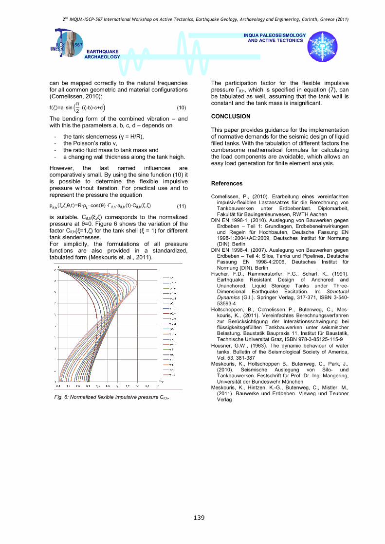
Flexible impulsive pressure Figure 4 shows the mode of vibration and the pressure distribution corresponding to the flexible impulsive pressure component. The flexible impulsive pressure component is calculated in an iterative procedure using the added-mass-model according to DIN EN 1998-4 (2007), Annex A. Within the framework of the procedure the tank wall is loaded with iterative calculated additional mass portions of the activated fluid. The pressure distribution is given by the expression: pif,h(ξ, ζ, θ, t) =
(6) 2RρL
I1νnγ ∙ ξ
νnγ ∙ I νn
γcos(νn∙ζ) f(ζ)∙ cos(νn∙ ζ) dζ
1
0
∞
n=0
⋅ [cos(θ)] aif,h(t) ∙ Γif,h
with: pif,h flexible impulsive pressure component due to
horizontal excitation f(ζ) deflection curve of the first (anti-symmetric)
mode of oscillation of the tank-fluid combination
aif,h(t) horizontal acceleration-time history as a result of an equivalent single-degree-of-freedom system. By using the response spectrum analysis the spectral accelerations corresponding to the first natural period Tif,h,1 should be used.
Γif,h participation factor for the flexible impulsive pressure component due to horizontal excitation
The participation factor Γif,h for the flexible impulsive pressure component is calculated as follows:
Γif,h=∫ pif,h(ζ)dζ10
∫ f(ζ) ∙ pif,h(ζ)dζ10
, s(ζ) = const. (7)
with: pif,h (ζ) pressure function of the flexible impulsive
pressure component as a function of the filling height
s(ζ) wall thickness of the tank Taking into account the pressure distribution of the tank shell (ξ = 1), equation (6) can be simplified to: pif,h(ξ=1, ζ, θ, t) =
(8) = R∙ρL 2∙I1
νnγ
νnγ I νn
γ∙cos(νn∙ζ) f(ζ)∙ cos(νn ∙ζ)dζ
1
0
∞
n=0
[cos(θ)] aif,h(t) ∙ Γif,h
The first natural period Tif,h,1 is calculated as follows:
Tif,h,1 = 2 ∙ F(γ)WL
π ∙ g ∙ E ∙ s(ζ = 1/3)
(9)
= 2 ∙ R ∙ F(γ)H ∙ρL
E ∙ s(ζ = 1/3)
with: WL fluid weight: WL = π ∙ R2∙ H ∙ ρL∙ g
F(y) correction factor: F(γ) = 0,157 ∙ γ2 + γ + 1,49 s(ζ = 1/3) wall thickness of the tank at 1/3 filling
height
The function curve of f(ζ) in (8) is generally not known. It depends on the impact of the liquid onto the tank, in other words the aforementioned pressure function pif.h. Thus the joint bending form must be correctly determined iteratively. In DIN EN 1998-4 (2007), Annex A the "added-mass concept" is proposed. According to this the resonating fluid, activated with the first bending shape, is added to the tank wall density. Then with the new "dry" tank model, the more accurate bending form is determined (Fischer et. al., 1991).
However as Figure 5 shows, even this iterative process is impractical because the calculation is based on a complex mathematical pressure function (6) which requires a coupling of a mathematical software tool with a finite element program. Though, with comprehensive parameter studies it is shown that the bending form of any tank can be described by using a parameterized sine wave which
Fig. 5: Iteration process (Holtschoppen et. al., 2011)
Fig. 4: Flexible impulsive pressure - Mode of vibration and pressure distribution.
2nd INQUA-IGCP-567 International Workshop on Active Tectonics, Earthquake Geology, Archaeology and Engineering, Corinth, Greece (2011)
INQUA PALEOSEISMOLOGY
AND ACTIVE TECTONICS
EARTHQUAKE ARCHAEOLOGY
139
can be mapped correctly to the natural frequencies for all common geometric and material configurations (Cornelissen, 2010):
f(ζ)=a⋅ sinπ2⋅(ζ-b)⋅c+d (10)
The bending form of the combined vibration – and with this the parameters a, b, c, d – depends on - the tank slenderness (γ = H/R), - the Poisson’s ratio ν, - the ratio fluid mass to tank mass and - a changing wall thickness along the tank heigh.
However, the last named influences are comparatively small. By using the sine function (10) it is possible to determine the flexible impulsive pressure without iteration. For practical use and to represent the pressure the equation
pif,h(ξ,ζ,θ,t)=R⋅ρL⋅ cos(θ) ⋅Γif,h⋅aif,h(t)⋅Cif,h(ξ,ζ) (11)
is suitable. Cif,h(ξ,ζ) corresponds to the normalized pressure at θ=0. Figure 6 shows the variation of the factor Cif,h(ξ=1,ζ) for the tank shell (ξ = 1) for different tank slendernesses. For simplicity, the formulations of all pressure functions are also provided in a standardized, tabulated form (Meskouris et. al., 2011).
The participation factor for the flexible impulsive pressure Γif,h, which is specified in equation (7), can be tabulated as well, assuming that the tank wall is constant and the tank mass is insignificant. CONCLUSION This paper provides guidance for the implementation of normative demands for the seismic design of liquid filled tanks. With the tabulation of different factors the cumbersome mathematical formulas for calculating the load components are avoidable, which allows an easy load generation for finite element analysis. References Cornelissen, P., (2010). Erarbeitung eines vereinfachten
impulsiv-flexiblen Lastansatzes für die Berechnung von Tankbauwerken unter Erdbebenlast. Diplomarbeit, Fakultät für Bauingenieurwesen, RWTH Aachen
DIN EN 1998-1, (2010). Auslegung von Bauwerken gegen Erdbeben – Teil 1: Grundlagen, Erdbebeneinwirkungen und Regeln für Hochbauten, Deutsche Fassung EN 1998-1:2004+AC:2009, Deutsches Institut für Normung (DIN), Berlin
DIN EN 1998-4, (2007). Auslegung von Bauwerken gegen Erdbeben – Teil 4: Silos, Tanks und Pipelines, Deutsche Fassung EN 1998-4:2006, Deutsches Institut für Normung (DIN), Berlin
Fischer, F.D., Rammerstorfer, F.G., Scharf, K., (1991). Earthquake Resistant Design of Anchored and Unanchored, Liquid Storage Tanks under Three-Dimensional Earthquake Excitation. In: Structural Dynamics (G.I.). Springer Verlag, 317-371, ISBN 3-540-53593-4
Holtschoppen, B., Cornelissen P., Butenweg, C., Mes-kouris, K., (2011). Vereinfachtes Berechnungsverfahren zur Berücksichtigung der Interaktionsschwingung bei flüssigkeitsgefüllten Tankbauwerken unter seismischer Belastung. Baustatik Baupraxis 11, Institut für Baustatik, Technische Universität Graz, ISBN 978-3-85125-115-9
Housner, G.W., (1963). The dynamic behaviour of water tanks, Bulletin of the Seismological Society of America, Vol. 53, 381-387
Meskouris, K., Holtschoppen B., Butenweg, C., Park, J., (2010). Seismische Auslegung von Silo- und Tankbauwerken. Festschrift für Prof. Dr.-Ing. Mangering, Universität der Bundeswehr München
Meskouris, K., Hintzen, K.-G., Butenweg, C., Mistler, M., (2011). Bauwerke und Erdbeben. Vieweg und Teubner Verlag
Fig. 6: Normalized flexible impulsive pressure Cif,h.