dynamic bending behaviour of woven composites for …d...loughborough university institutional...
TRANSCRIPT
Loughborough UniversityInstitutional Repository
Dynamic bending behaviourof woven composites for
sports products: experimentsand damage analysis
This item was submitted to Loughborough University's Institutional Repositoryby the/an author.
Citation: ULLAH, H., HARLAND, A.R. and SILBERSCHMIDT, V.V., 2015.Dynamic bending behaviour of woven composites for sports products: experi-ments and damage analysis. Materials and Design, 88, pp.149-156
Additional Information:
• This paper was accepted for publication in the journal Materi-als and Design and the definitive published version is available athttp://dx.doi.org/10.1016/j.matdes.2015.08.147
Metadata Record: https://dspace.lboro.ac.uk/2134/19456
Version: Accepted for publication
Publisher: c© Elsevier
Rights: This work is made available according to the conditions of the Cre-ative Commons Attribution-NonCommercial-NoDerivatives 4.0 International(CC BY-NC-ND 4.0) licence. Full details of this licence are available at:https://creativecommons.org/licenses/by-nc-nd/4.0/
Please cite the published version.

Dynamic bending behaviour of woven composites for sports products: Experiments and damage analysis
HIMAYAT ULLAH1, ANDY R. HARLAND, VADIM V. SILBERSCHMIDT*
Wolfson School of Mechanical and Manufacturing Engineering, Loughborough University, Leicestershire, LE11
3TU, UK
*Corresponding author: Ashby Road, Loughborough, Leics., LE11 3TU, UK. Phone: +44 1509 227504.
Fax: +44 1509 227502, Email: [email protected]
1Present address: National University of Sciences and Technology, College of E&ME, Peshawar Road,
Islamabad, Pakistan; Email: [email protected]
ABSTRACT
Carbon fabric-reinforced polymer (CFRP) laminates employed in sports products are usually subjected to large-
deflection quasi-static and dynamic bending deformations during service. Such loading conditions induce
damage in the material, affecting its strength, stiffness and energy-absorbing capability. To study this,
mechanical behaviour of woven CFRP composites in on- and off-axis orientations is first quantified by carrying
out large-deflection quasi-static bending tests followed by dynamic ones employing an Izod-type impact tester.
CFRP laminates of various orientations were tested at loads increasing up to failure to determine their energy-
absorbing capability. On-axis laminates demonstrated better strength and stiffness whereas off-axis laminates
exhibited good energy-absorbing capability. However, for applications demanding strength, stiffness and energy
absorption as in sports products, a combination of both types of plies, as in a quasi-isotropic layup, is an
optimum choice. Micro-computed tomography (micro-CT) analysis of the tested specimens showed that matrix
cracking, delamination and tow debonding were the dominant damage modes at the specimen’s impact location,
whereas fabric fracture occurred at the bending location. Further, a catastrophic brittle fracture was observed in
the on-axis laminates whereas the off-axis laminates exhibited pseudo-ductile behaviour thanks to matrix
cracking and fibre trellising before their failure at higher energies.
Keywords: CFRP; Dynamic bending; micro-CT, Delamination; Fracture
1. Introduction
Woven composites such as CFRP laminates are increasingly used in aerospace, automotive and energy
components and structures thanks to their higher impact resistance and damage tolerance and better
manufacturability as compared to unidirectional laminates [1]. Improvements in manufacturing processes and
cost reduction caused an extensive use of composites in sporting goods ranging from tennis rackets, skis, sports
gears, sports bicycles, hockey sticks, baseball and cricket bats, fishing rods, oars and paddles, archery bows to
running shoes. In many of these applications, composites are replacing traditional materials such as metals, wood
and leather thanks to their higher specific strength, specific stiffness, weight reduction, energy absorption,
vibration damping as well as improved design and manufacturing flexibility [2]. Importantly, these material
properties result in performance improvements that enable athletes to compete at a higher level with less effort
and fatigue. For example, lighter composite structures result in higher speeds and quicker manoeuvring in
bicycle and boat racing; lighter and stiffer tennis rackets and golf clubs can hit the ball faster and farther with
more comfort, while better toughness and vibration damping in sports shoes can result in faster and longer

running by athletes. In athletic footwear insoles, composite laminates are nowadays used to enhance the runner’s
comfort thanks to the material’s better energy absorption and fewer injuries thanks to better impact resistance [3].
Footwear is subjected to repeated impacts as the heel strikes the ground during running. As shown in Fig. 1, a
typical vertical reaction force with two peaks is generated in heel-strike during running. The first peak known as
the passive load cannot be cushioned by human movement as its duration is too short for a human to make a
cushioning movement. Hence, since this impact load is considered as the source of injuries, it needs to be
cushioned by a shoe material [4]. Further, the peak forces generated during a heel strike are 2-3 times the
runner’s body weight, and the number of impacts is around 1500 per mile, varying between subjects [5]. Due to
repetitive impacts and high loading rates in running, it is more likely that injuries occur to the bones and tissues
of human legs. Therefore, among the main design requirements for athletic footwear are impact and shock
resistance, better damping and energy absorption, higher strains to failure and strain rates, higher stiffness and
light weight for better comfort of runners. Nowadays, sports industry focuses on innovations in sports shoes in
areas of materials, motion control of foot, mass and athletics design. Carbon fabric together with the embedding
thermoplastic polyurethane matrix offers these unique properties to footwear insoles. Thin strips of CFRP
laminates are sandwiched in the midsole between EVA foam or polyurethane, especially at the heel’s region
subjected to higher impact loads.
Fig. 1. Vertical ground reaction force during running
In sports products such as skis, rackets, golf clubs, hockey sticks, baseball bats and athletic footwear, composite
structures can experience large-deflection bending caused by quasi-static loading and low-velocity impacts
during their service. For instance, during running, a sports shoe acts as a cantilever at heel when struck with
ground, and the rest of the sole experiences large-deflection bending; which cannot be replicated in drop-weight
testing, where flexure is significantly constrained. Although the behaviour of fabric-reinforced composites
subjected to low-velocity impact is widely studied, e.g. in [6-10], among others, the loading is mostly of the
drop-weight type. The large-deflection dynamic bending behaviour of sports products can be accurately assessed
with impact tests on un-notched samples using pendulum-type hammers, which is rarely investigated. Further,
kinematics and biomechanics of running are studied to some extent as in [4, 11, 12]; however, characterisation of
composite materials for such applications is a novel area to be dealt with in this manuscript.

In this paper, the flexural behaviour of woven CFRP laminates in warp, weft and off-axis orientations is studied
first under large-deflection quasi-static bending. The experimental tests characterised the stiffness, strength and
toughness of CFRP laminates. The CFRP laminates are then tested under large-deflection dynamic bending at
various levels of impact energy – up to the material’s failure. The tests quantified dynamic strength and energy-
absorbing capability of CFRP laminates of different orientations. In the tested laminates, various damage modes
such as matrix cracking, fibre breakage, tow-matrix debonding, delamination and fabric fracture were analysed
with an X-ray micro-CT technique. Micro-CT can provide a full-field high-resolution 3D representation of
internal damage modes and their coupling in composites non-destructively as compared to conventional 2D
damage-assessment techniques. This relatively recent technique was also employed in [13-15] to analyse damage
behaviour of composites at micrometre scale.
2. Experimental methods
2.1 Materials
The CFRP composites were prepared from carbon fabrics with areal density of 200 g/m2 reinforced with TPU
matrix. The 2D woven preform consisted of T200 carbon fibres with filament diameter of 7 µm and 3k tow size.
All configurations were produced in a 2/2 twill symmetric weaving pattern with a similar fibre volume fraction
of 45%. These materials were specially developed for sports applications requiring higher energy-absorption
capability. Hence, a ductile TPU matrix with a higher volume fraction of 55% was used. The TPU resin is a
tough polymer that provides a better resistance to impact and fatigue, making it suitable for applications
demanding shock and energy absorption, especially in sports products. Further, thermoplastic matrices such as
TPU, polyphenylene sulphide (PPS), and polyether-ether-ketone (PEEK) are also increasingly employed in
composite structures due to their higher fracture toughness resulting in a better resistance to impact damage than
thermosetting matrices such as epoxy-based composites [16].
The 1 mm-thick specimens were produced from 0°/90° prepregs using four fabric layers designated as [0°,90°]2s,
with [0°,90°] representing a single fabric (ply), where 0° and 90° are the warp and weft directions of tows,
respectively. In this study, the stacking orders of the form [0°,90°]2s and [90°,0°]2s are designated as warp and
weft specimens, respectively, also known as specially orthotropic (on-axis) laminates as the plies’ orientations
coincide with the global orientations in the laminate/structure. Another type of a generally orthotropic (angle ply)
laminate, where the plies’ orientations are at an angle to the laminate orientation, in the form of [+45°/-45°]2s is
designated as off-axis specimen. It was also observed from the micro-CT of the specimens that the ends and
picks count was 5.2 and 5.14 per cm, respectively. Due to this minor difference, the number of tows in the warp
and weft specimens along their longitudinal plane was 13 and 12.85, respectively, based on 25 mm width of the
specimens tested. Detailed parameters of the twill woven CFRP composites are given in the authors’ work [15,
17].
In this paper, three types of woven CFRP specimens designated as warp, weft and off-axis were first tested under
three-point-bending conditions. In the quasi-static bending tests, five flat rectangular specimens of dimensions
80 mm (length) × 25 mm (width) × 1 mm (thick) were used for each orientation. However, for dynamic bending
tests, un-notched rectangular specimens of 40 mm × 25 mm × 1 mm were employed for each of three
orientations. In these tests, first five specimens for each orientation were used; however, after confirming
repeatability of the obtained test results, two specimens per test were found to be sufficient for obtaining reliable
results.

2.2. Quasi-static bending tests
The quasi-static bending tests were performed at indenter speed of 100 mm/min (strain rate 0.0417 s-1) according
to ASTM D790 standard using the Instron 5569 machine. A loading span between the supports was kept at 40
mm in all the three-point bending tests; the tests were performed in the displacement-control regime. The
obtained bending stress-strain diagrams for each orientation of CFRP laminates are shown in Fig. 2. In both
types of on-axis specimens, flexural tests of warp and weft laminates demonstrated a quasi-brittle behaviour. The
reason for this material behaviour is that in on-axis laminates, the applied load is carried by the fibres, which are
strong but brittle. Thus, the stress-strain curves are almost linear up to the specimen’s catastrophic fracture,
represented by an abrupt drop of the stress level in Fig. 2. The maximum stress of 990 MPa in the warp
specimen corresponded to a flexural load of 422 N, which is still less than the maximum load-bearing ability of
about 1500 N of a human body during running (Fig. 1), thus causing no fatigue/injuries to human body. As
presented in Table 1, the flexural tests resulted in slightly different elastic moduli and flexural strengths for both
warp and weft specimens because of the little difference in the ends/pick count of the fabric structure. Stiffness
reduction due to internal damage occurred in wrap specimens at about 90% of the ultimate load, whereas the
weft laminates exhibited no stiffness reduction before ultimate fracture. As described in Section 2.1, the number
of tows/fibres along the longitudinal plane in warp specimens was a little higher than that of weft specimens;
thus, the warp specimens resisted the bending load slightly better than the weft ones. With increasing the load,
one or more aligned stiff tows ruptured earlier, at about 90% of the ultimate load, causing the load drop before
catastrophic failure of the warp specimens in the stress-strain diagram shown in Fig. 2. Hence, these specimens
gave no warning before their brittle catastrophic failure unlike metals, which is a major drawback to their
outstanding mechanical properties, especially in applications demanding energy absorption and yielding. This
inherent brittleness of on-axis laminates results in higher safety margins for composites compared to metals. The
elastic flexural moduli, ultimate flexural strength, maximum deflection, strain to failure and specific energy
absorption, calculated from the mechanical tests of the warp, weft and off-axis specimens, are listed in Table 1.
Here, the strains to failure are somewhat higher than those of epoxy-based CFRP laminates due to compliant
TPU matrix. Bergmann et al. [18] studied the effect of thermoset as well as thermoplastic matrices such as epoxy
and PEEK, respectively, on the mechanical properties and energy-absorption capability of woven fabric-
reinforced composites subjected to ±45° off-axis tensile loading. For the same loading conditions, fabric type
and laminate stacking, they found that thermoplastic PEEK-based composites resulted in an increase in elastic
modulus of 26.5%, tensile strength of 17% and strain-to-failure of 10.5% than that of epoxy-based composites.
Due to their better mechanical properties, fabric-reinforced composites with thermoplastic matrix such as TPU
are employed for sports applications in this study.
Table 1: Mechanical properties and specific energy absorption of CFRP laminates under quasi-static bending
Orientation Flexural
modulus
(GPa)
Ultimate
flexural strength
(MPa)
Maximum
deflection
(mm)
Strain to
failure (%)
Specific energy
absorption
(kJ/kg)
Warp [0°,90°]2s 55.0 ± 1.5 993.0 ± 25 5.1 ± 0.3 1.85 ± 0.07 6.2 ± 0.4
Weft [90°,0°]2s 52.0 ± 1.4 885.0 ± 23 4.75 ± 0.26 1.76 ± 0.06 5.1± 0.3
Off-axis [+45°/-45°]2s 16.3 ± 1.1 478.0 ± 11 8.75 ± 0.36 4.5 ± 0.1 8.5 ± 0.6

Fig. 2. Stress-strain diagram from quasi-static flexural tests of twill 2/2 CFRP specimens
As shown in Fig. 2, the off-axis specimens demonstrated a large-deformation nonlinear behaviour before their
ultimate failure as compared to their on-axis counterparts. This ductile behaviour is due to matrix plasticity as
well as cracking and alignment of tows along the loading directions called fibre trellising. The latter is the result
of fibres reorientation towards the loading direction, with the angle between warp and weft fibres changing from
90° with increasing the load level. This behaviour is more pronounced in off-axis specimens tested under
uniaxial tensile loads resulting in strains to failure up to 30% as studied in [19]. Such ductile, or yielding
behaviour of composites is more desirable for energy-absorption purposes and is termed pseudo-ductility in
recent research works such as [20]. Recently, various approaches, such as partially discontinuous ply architecture
[21], hybrid laminates with higher ductile fibres, intermingled cuts, single-polymer composites [22] and off-
axis/angle-ply laminates have been proposed to improve the yielding behaviour of composites. In this work, this
pseudo-ductility in angle-ply laminates is studied for sports applications for the first time. Thanks to such
behaviour, the off-axis laminates are still capable to bear a load after the damage initiated at the yield point (Fig.
2). Here, the yield point refers to the knee where the stress-strain curve deviates from the initial elastic line and
does not necessarily indicate the presence of plastic deformation as observed in metals. Further, the off-axis
specimens exhibited higher levels of strain to failure - 4.5% - than the on-axis specimens. The specific energy
absorption, calculated from the area under the stress-strain curve divided by the material density (1450 kg/m3),
was 8.5 kJ/kg, which is some 60% higher than that of the on-axis specimens (Table 1). However, the increase in
energy-absorption capability is accompanied by a reduction in stiffness and strength properties of the tested off-
axis specimens. These properties can be improved by selecting ply angles in the range from 20° to 30°
depending on various applications. Still, it is evident that off-axis laminates are capable to plastically deform and
absorb energy like metals before their ultimate failure. Further, it was reported in [18] that thermoplastic PEEK-
based composites demonstrated in 10% higher specific energy absorption than epoxy-based composites tested
under similar conditions.
2.3. Dynamic bending tests
2.3.1. Experimental procedure

Dynamic tests were performed to characterise the bending behaviour of composite laminates under low-velocity
impact regimes characteristic of the sports products in their service. Dynamic bending tests in an impact energy
range from 0.1 J to 1.2 J were carried out according to the ASTM D4812 standard using a pendulum-type
CEAST Resil impactor as shown in Fig. 3. In these tests, the bottom of the specimen was held in a clamping vice,
whereas its upper part (30 mm) was struck by the impactor with specified impact energy, resulting in dynamic
large-deflection flexure. With the same mass of impactor, the impact energy levels were varied by changing the
initial angle of the hammer. A piezoelectric force sensor was fixed to the hammer’s striker to measure the impact
load. The data acquisition was achieved using DAS 8000 system at 227 kHz frequency. The force-time history of
the dynamic event was recorded. The rest of the dynamic test parameters can be calculated using the equations
given below, with the assumption of perfectly rigid impactor. The hammer’s initial velocity at the moment just
before the contact takes place can be determined from the potential energy using the following equation:
𝑣𝑣𝑖𝑖 = �2𝑔𝑔ℎ𝑑𝑑 , (1)
where 𝑣𝑣𝑖𝑖 is the velocity at impact, ℎ𝑑𝑑 is the drop height, and 𝑔𝑔 is the acceleration of gravity. By integrating the
force history, the hammer’s velocity 𝑣𝑣(𝑡𝑡) , deflection 𝛿𝛿(𝑡𝑡) , and absorbed energy 𝐸𝐸𝑎𝑎 can be determined,
respectively, using the following equations:
𝑣𝑣(𝑡𝑡) = 𝑣𝑣𝑖𝑖 −1𝑚𝑚 ∫ 𝐹𝐹(𝑡𝑡)𝑑𝑑𝑡𝑡𝑡𝑡
0 , (2)
𝛿𝛿(𝑡𝑡) = ∫ 𝑣𝑣(𝑡𝑡)𝑑𝑑𝑡𝑡𝑡𝑡0 , (3)
𝐸𝐸𝑎𝑎 = 𝑚𝑚2
(𝑣𝑣𝑖𝑖2 − 𝑣𝑣2). (4)
Fig. 3. Resil test set-up for impact bending
2.3.2. Results and discussion

The transient bending response of CFRP laminates in the warp, weft and off-axis orientations was evaluated in
impact tests at energy levels ranging from 0.1 J – 1.2 J. The dynamic response of the material includes the load,
deflection, and energy as functions of time. Diagrams of evolution of load-time, load–deflection and energy-time
graphs were plotted for representative samples at each energy level. Key impact parameters such as peak load,
time to peak load and deflection at peak load were evaluated by the data acquisition system, and are elaborated
in this section.
Force-time response
The impact force-time responses of CFRP warp, weft and off-axis specimens tested at different energy levels are
illustrated in Fig. 4. It can be observed that both the slope and maximum peak force of the curves increased with
impact energy. At lower impact energies, the force increased linearly with time at the beginning of impact,
indicating the behaviour of undamaged specimen. After the maximum load peaks, the hammer bounced back and
the load reduced to zero. The loading and unloading portions of the curves for both the warp and weft specimens
up to 0.4 J and off-axis specimens up to 0.3 J had a nearly symmetric parabolic shape; indicating the occurrence
of little damage in the form of a dent or matrix cracking at the impact point. In these impact tests, the energy was
rather stored elastically in the specimens like a spring. As the impact energy was increased to 0.5 J and 0.4 J for
warp and weft specimens, respectively, oscillations in the force-time plots can be observed before the load peaks.
These fluctuations associated with load drops are designated as Fdi in Figs. 4a and b, representing the onset of
damage such as delamination and matrix cracking linked with reduction in the laminate stiffness [23, 24]. The
curves became non-symmetric with regard to their peaks at 0.5 J as can be seen in Figs. 4a and b. In these tests,
at 0.6 J impact energy, fabric fracture occurred in both types of specimens denoted by an abrupt drop in impact
force indicating a loss of contact between the hammer and laminate. This was caused by brittle fracture of the
fabric in tension in the front face of the specimen as a result of bending. The force did not reduce to zero in the
warp specimens, as the back-face plies under compression were not fractured, causing a residual load of about 20
N. However, in the weft specimen, the load dropped to zero representing the laminate’s complete fracture.
In the off-axis specimens, as the impact energy increased up to 0.4 J, the loading and unloading parts showed
nonlinear behaviour instead of oscillations, demonstrating that plasticity of the laminates resulted in a lower
level of damage in them than in on-axis specimens. The specimens impacted at energies between 0.8 J – 1.1 J
also showed a permanent bending-like deflection after tests (Fig. 4c), which might be due to pseudo-plasticity of
the off-axis laminates. The plasticization of matrix in the resin-rich regions also played an important role by
leading to local permanent deformations due to ductility of the TPU matrix, apart from fibre trellising. At higher
energy levels, the specimens exhibited more pronounced yielding, implying the onset of plastic deformation
indicated by the plateau at the top of the curves (Fig. 4c). The specimens also exhibited a snap-back during the
rebound, shown by the depths and kinks in Fig. 4c. Unlike the on-axis specimens, the peak loads remained
almost the same, with an appreciable increase in the deformation of the off-axis specimens at higher impact
energies. The off-axis specimens failed at higher impact energy of 1.2 J than the on-axis specimens, but the
failure was not sudden and catastrophic, giving a warning in the form of load reduction (Fig. 4c). Here, a residual
load remained after failure, and the specimens were still intact as can be seen from micro-CT images in Fig. 12.
In both types of warp and weft specimens, the impact force increased with the impact energy, however, with a
little effect on the contact durations (Fig. 4). The reason is that higher impact velocities induced larger
deformations and, therefore, larger impact forces.

Fig. 4. Force-time responses of CFRP warp (a), weft (b) and off-axis (c) laminates at various impact energies
Further, the contact durations remained almost the same with increase in the impact velocity for on-axis
specimens. Such a response indicates that the material’s behaviour is strain-rate-independent under dynamic
loading in fibre-dominated modes as was also observed in [25]. However, the off-axis specimens exhibited a
rate-dependent behaviour due to their matrix-dominated response, as the contact duration increased with the
impact energy (Fig. 4c). The peak loads for the on-axis specimens were higher than those of the off-axis ones at

the corresponding energy levels due to the higher material’s stiffness (see Table 1). The latter also resulted in
lower contact duration for the on-axis specimens than that for the off-axis specimens at the respective impact
energy levels. However, the off-axis specimens did not exhibit a catastrophic brittle fracture like the on-axis
specimens but rather demonstrated behaviour similar to yielding at higher impact energies (Fig. 4c). This implies
that although off-axis laminates are less strong, they can tolerate higher impact energy before their failure. In
experiments, the specimens failed at low energy levels because of lower flexural rigidity due to their boundary
conditions and geometric parameters.
Force-deflection response
The force-deflection (F-d) responses for the warp, weft and off-axis configurations of CFRP samples at different
impact energy levels are given in Fig. 5. Actually, all the curves started from the origin but due to higher
Hertzian stiffness between the hammer and the specimen at the start, the load seemed to start from non-zero
values. In cases without impact damage, a peak load relates to the maximum resistance provided by the specimen
as an indication of its flexural stiffness [24]. The slope of F-d curves indicates the contact stiffness, while the
area under the curve is the energy absorbed, which is increased with impact energy. It is worth mentioning that a
membrane stiffening effect also occurred in thin laminates as the maximum deflection was several times greater
than the specimen’s thickness.
In the materials under study, apart from the pseudo-ductility in angle-ply laminates, the TPU matrix was highly
ductile and, thus, absorbed more energy without inducing any appreciable damage. Here, again, there is a
significant difference in the behaviour of the on-axis specimens as compared to the off-axis specimens. For the
on-axis specimens, stiffness (the slope of the load–deflection curve) showed a significant linear increase with the
impact energy, whereas, for the off-axis specimens only a small increase in stiffness was observed, as was also
the case in quasi-static tests. The increase in stiffness can be associated with higher values of the Young’s
moduli of the on-axis laminates than that of the off-axis laminates (Table 1). Due to lower stiffness, the
maximum deflection of the off-axis specimens was almost double than that of the on-axis specimens at the
respective impact energy levels resulting in higher strains–to-failure magnitudes. From the F-d curves in Figs. 5a
and b, stiffness of the on-axis specimens was 5.8 N/mm, 8.5 N/mm, 9.1 N/mm, 9.3 N/mm, 11.6 N/mm and 12.6
N/mm for impact energy levels of 0.1 J, 0.2 J, 0.3 J, 0.4 J, 0.5 J and 0.6 J, respectively. However, the quasi-static
flexural tests of on-axis specimens resulted in a higher value of about 85.8 N/mm. Similarly for off-axis
laminates, the stiffness form F-d curves (Fig. 5c) was about 2.6 N/mm (almost the same for all energy levels) as
compared to its quasi-static value of 35 N/mm. This discrepancy was due to the boundary conditions of
specimens in both types of testing. In quasi-static tests, the specimen acted as a simply supported beam whereas
in dynamic ones, the specimen was like a cantilever beam. It is evident from the basic beam theory that the
stiffness of simply supported beam is almost 16 times higher than that of a cantilever one; a mismatch of this
order is represented when the stiffness of 0.1 J F-d curves is compared with quasi-static one for both the on-axis
and off-axis specimens.
The initiation and progress of damage were evident by oscillations in the load at higher energy levels for the on-
axis specimens, whereas the off-axis specimens exhibited pronounced nonlinearity due to matrix plasticity and
fibre trellising (pseudo-ductility). The latter also resulted in larger areas under the F-d curves for off-axis
specimens indicating their higher energy absorption capabilities before failure. Further, it was also observed that
the off-axis laminates required higher impact energies for specified damage and failure.

Fig. 5. Force-deflection responses of CFRP warp (a), weft (b) and off-axis (c) laminates at various impact
energies
Vieille et al. [16] conducted a comparative study on the impact behavior of woven carbon fiber-reinforced
composites with thermoplastic matrices such as PEEK and PPS as well as thermosetting matrix such as epoxy
composites. They observed that thermoplastic-matrix composites demonstrated higher damage tolerance and
energy absorption capability than epoxy-based ones. It was found that the latter displayed larger delaminated
areas, reaching values about twice as high for low impact energies; thus, tougher thermoplastic matrices resulted
in better impact performance.

Energy-time response
Variation of energy with time for the warp, weft and off-axis CFRP specimens at different impact energies is
shown in Fig. 6. As the impactor hit the specimen, the latter started absorbing the impactor’s kinetic energy. The
energy increased during loading until a maximum value and then decreased during a rebound and ultimately
remained horizontal. This constant value gives the total energy absorbed by the specimen at the end of an impact
event. Energy absorption in composites is mainly through elastic strain energy, plastic deformation and
formation of various damage mechanisms [26].
Fig. 6. Energy-time responses of CFRP warp (a), weft (b) and off-axis (c) laminates at various impact energies

As studied in Section 2.2, the on-axis composite laminates exhibited quasi-brittle behaviour; thus, there was no
associated plastic deformation. In these specimens, impact energy was absorbed through elastic deformation as
well as development of various damage modes. However, the off-axis laminates exhibited a metal-like ductile
behaviour before their failure and, hence, absorbed larger amounts of energy through plasticity, making them a
preferable material for energy-absorption requirements as in sports products. Further, as shown in Fig. 6, the
energy absorbed by the specimens increased with the impact energy since higher impact energy resulted in large
deformation and damage to the specimens. In the on-axis specimens, the energy decreased slightly after reaching
its maximum value representing little rebounding of the hammer. However, for the off-axis specimens, the
energy remained constant after reaching its maximum value, showing no rebound. Still, in the tests of all types
of specimens, the hammer rebounded at low energies. This may be due to the fact that the complaint TPU matrix
absorbed the energy in the on-axis laminates augmented by plasticity in the off-axis specimens. At impact energy
of 0.6 J, the absorbed energy reached a value of 0.46 J at 5.5 ms and then gradually increased till 0.55 J at 8 ms
and remained constant after fracture of the warp tests. In the weft tests, the absorbed energy reached a value of
0.55 J at 5.5 ms and then became constant. In the off-axis tests, this happened at 11 ms, with absorbed energy of
1.05 J. The stabilized energy levels indicated that the specimens fractured and the impactor lost contact with
them. Similar energy profiles were also obtained for thin glass-fibre woven laminates under impact loads studied
in [27].
Fig. 7. Variation of absorbed energy with impact energy of CFRP warp, weft and off-axis specimens
Variation of the absorbed energy with impact energy, i.e. energy profile diagram is plotted for the warp, weft and
off-axis specimens in Fig. 7. Here, the points below the equal energy line (a bisector) show the remaining energy
retained by the impactor and used to rebound it from the specimen at the end of impact [27]. Here, too, the
rebounding phenomena were exhibited more by the on-axis specimens than the off-axis. The energy profile
diagram also showed that the off-axis specimens absorbed more energy without any rebound represented by an

almost straight line than the on-axis specimens. At impact energy of 0.6 J, both types of warp and weft
specimens showed fracture after absorbing lower amounts of energy. This also implied that the hammer did not
result in further damage in the laminates even if the impact energy increased. However, the off-axis laminates
showed greater energy-absorbing capability up to impact energy of 1.2 J prior to their ultimate fracture.
3. Micro-computed-tomography analysis of damage
Micro computed tomography was used to analyse a 3D nature of various damage modes and their location in the
impacted CFRP specimens at microstructural level. The gathered information can be used for damage-tolerant
design as well as simulation of actual damage modes in composites employed in sports products. In this work, an
XT H 225 X-ray scanner was employed for 3D scanning. Its X-ray source is a sealed tube operating at voltage
range of 25–225 kV with a 3 μm spot size. An object manipulator positioned the sample to a specific region of
interest (ROI) for acquisition of tomographic data. Detailed information of internal damage in the specimens
needs high-resolution scanning. Thus, increased resolution results in reduction of the field of view (FOV) of the
sample. However, samples must be positioned within the FOV to acquire the data of the ROI; therefore, a trade-
off is needed. In this work, the reconstruction of tomographic data was performed using CT-Pro software, and
the analysis of the resulting 3D volumes was implemented with the VG Studio Max 2.2 software to partition and
highlight the ROI. Since the dynamic behaviour of warp and weft specimens was almost similar, only damage
characterisation of the warp specimens at two energy levels along with off-axis specimens is presented.
Fig. 8. Tomographic 3D images of warp specimen at impact location along the height of sample: (a) full; (b) half;
(c) one-third of hight
3.1. Analysis of damaged warp specimen
A sample of 20.6 mm length, 10.2 mm width and 1 mm thickness from the impact location of the damaged
CFRP warp specimen impacted at 0.5 J was prepared for 3D scanning. The sample was exposed to X-rays
generated at 75 kV and 80 μA. Radiographic images were obtained from 3600 rotation views over 360° of
rotation (0.1° rotation step) during 3D reconstruction. The tomographs thus reconstructed, had a resolution of
14.7 µm for the impact specimen, and are illustrated in Fig. 8. These tomographs demonstrate cracks in the TPU
matrix and delamination at the impact point along the sample’s height. Matrix cracks developed in weak resin
dominated regions around the yarns and initiated inter-ply delamination. Micro-CT analysis showed that matrix
cracking and interlaminar delamination were the significant damage modes underneath the impactor contact zone.
3.2. Analysis of fractured warp specimen
The CFRP warp specimen fractured at 0.6 J impact energy was also scanned employing micro-CT at the impact
as well as fracture (bending) location. Here, to obtain high-resolution images, two small samples, one with
dimensions of 10.14 mm x 6.0 mm x 1.0 mm (W x H x T) from the impact region, and the second with
dimensions of 8.35 mm x 6.10 mm x 1.0 mm from the fractured region were prepared. The radiographic data
was generated at 80 kV and 85 μA of energy levels of X-rays. Here, too, for 3D reconstruction, radiographs were
acquired with rotation step of 0.1°. The obtained tomograms had resolution of 6.7 µm and 6.1 µm for the impact
and fractured specimens, respectively.
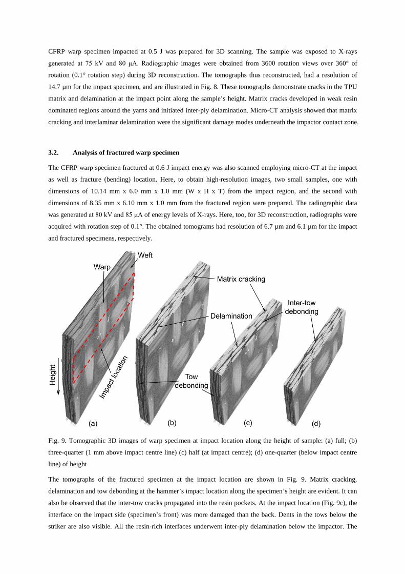
Fig. 9. Tomographic 3D images of warp specimen at impact location along the height of sample: (a) full; (b)
three-quarter (1 mm above impact centre line) (c) half (at impact centre); (d) one-quarter (below impact centre
line) of height
The tomographs of the fractured specimen at the impact location are shown in Fig. 9. Matrix cracking,
delamination and tow debonding at the hammer’s impact location along the specimen’s height are evident. It can
also be observed that the inter-tow cracks propagated into the resin pockets. At the impact location (Fig. 9c), the
interface on the impact side (specimen’s front) was more damaged than the back. Dents in the tows below the
striker are also visible. All the resin-rich interfaces underwent inter-ply delamination below the impactor. The

tomographs of the CFRP specimen at the fractured location presented in Fig. 10 demonstrate interlaminar and
intralaminar damage mechanisms at various positions along the sample’s width. It is evident that the specimen
exhibited progressively matrix cracking and then delaminations and tow debondings until its ultimate fracture.
Matrix cracking was dominant in the resin-rich regions surrounding the tows. Interlaminar delamination, i.e.
separation between adjacent fabric plies, and intralaminar delamination such as tow debonding, which is
separation between tows within a single ply, can also be observed. In the fibre-rich regions, the apparent damage
mode was debonding at the tow/matrix interface. The analysis of internal structure showed that at the time of
fabric fracture, triggered by tensile fibre failure, almost every ply was delaminated. This delamination is more
pronounced in Figs. 10a and c than in 10b and d. The reason is that warp tows, which are aligned along the
specimen’s axis, bear a higher load than transverse weft tows in bending of the specimen under impact. All the
tomographs demonstrate that matrix cracking, delamination and tow debonding were the significant damage
modes at the specimen’s impact location, whereas at the bending location, apart from these modes, fabric
fracture was also observed.
Fig. 10. Tomographic 3D images of warp specimen at bending (fracture) location along the height of sample: (a)
Full; (b) three-quarter; (c) half; (d) one-quarter of width
In this damage analysis, both large- and small-size samples from the impact region were scanned in an attempt
to investigate various damage modes at different resolutions. At lower resolution of 14.7 µm, only some major
damage modes in the form of matrix cracking and delamination were observed (Fig. 8). Reducing the sample
size by almost half resulted in images with 6.7 µm resolution that showed tow debonding apart from the matrix
cracking and delamination (Fig. 9). Hence, it is evident that increasing the sample size results in loss of realistic
damage information, while reducing the sample size limits the analysis to a localized region. This limits the use
of the micro-CT technique, preventing a study of a complete damage picture in a full-scale specimen. Therefore,
here, too, a trade-off is needed between the sample size and the requisite damage information. However, micro-
CT is still surpassing all other damage characterisation techniques in that it provides complete 3D internal
information for the materials.

Fig. 11. Tomographic 3D images of off-axis CFRP specimen at impact location along the width of sample: (a)
full; (b) three-quarter; (c) half; (d) one-quarter of width
3.3. Analysis of fractured off-axis specimen
Here, two samples of the off-axis CFRP laminates, one with dimensions of 6.42 mm x 6.0 mm x 1.0 mm from
the impact region, and second with dimensions of 21.4 mm x 14.1 mm x 1.0 mm from the bending/fractured
region were prepared. The tomographs with resolution of 4.5 µm and 15.4 µm for the impact and fractured
specimens, respectively, were obtained from the reconstruction process. These tomographs of the off-axis
fractured specimen at the impact and the bending locations are presented in Figs. 11 and 12, respectively. In Fig.
11, the sample shows similar damage modes of matrix cracking, delamination and debonding as in the on-axis
specimens. However, the extent of damage is less than in the on-axis specimens. In the off-axis laminates,
thicker interlaminar and intralaminar resin-rich regions are present than in the on-axis ones. In these laminates,
the elasto-plastic TPU matrix sharing almost 50% of load with fibres in ±45° orientation was yielded ahead of
the crack tip during cracking and delamination; thus enhancing fracture toughness of the woven composites and
suppressing damage. The sample at the bending location in Fig. 12 also highlighted similar damage modes with
additional fabric fracture on the tension (impact side) of the specimen. However, due to plasticity, this fracture
was not as catastrophic as occurred in the on-axis specimens, pierced in two pieces as shown in Fig. 10. Here,
the specimen was intact even after the fracture of fabric on its tension side, as shown in Fig. 12, thanks to intact
tows/fibres on the compression side. Therefore, it is evident that pseudo-ductility in the off-axis specimens
resulted in damage suppression under dynamic loading.
It is obvious from this analysis that, compared to drop-weight tests, different kinematics of the large-deflection
bending resulted in substantial difference in formation of damage modes. In the former, for similar composites,
hit with a hemispherical impactor, damage formation is in the form of a cone, beginning from fibre fracture and
delamination at the bottom surface and progressing towards the top of the laminate, as inspected in [23, 27]. In
this study, at the impact location for the warp specimen in Fig. 9c, the interface on the impact side (specimen’s
front side) was more damaged than the back side. Additionally, in this study, no fibre fracture occurred at the

back face, and only minor dents below the striker were observed on the impacted face as shown in Fig. 9. The
impact location experienced matrix cracking and delamination as shown in Figs. 9c and d. Here, the fabric
fracture was observed only at the bending location.
Fig. 12. Tomographic 3D images of off-axis CFRP specimen at bending (fracture) location along the width of
sample: (a) full; (b) three-quarter; (c) half; and (d) one-quarter of width
4. Conclusions
In this study, experimental tests were first performed to investigate quasi-static behaviour of CFRP laminates in
three different configurations of warp, weft and off-axis layups. These tests revealed the high values of strength
and modulus but low strains to failure and specific energy absorption of the on-axis laminates as compared to the
off-axis laminates. Further, the off-axis laminates demonstrated ductile behaviour before their ultimate failure as
compared to linear-elastic stress-strain behaviour of the on-axis laminates, but with lower stiffness and strength.
The specimens were then tested under large-deflection dynamic bending at various levels of impact energies up
to their ultimate fracture, to replicate the in-service loading scenarios of sports products. Load-time, load–
deflection and energy-time diagrams were used to evaluate the dynamic behaviour of the materials at various
energy levels. In the tests of the on-axis (specially orthotropic) laminates, at sub-critical energy levels, the load
drops before the peak exhibited damage initiation; whereas the ultimate laminate brittle fracture was
characterised by a sudden load drop in the force history plots at the critical energy level. On the contrary, the off-
axis specimens exhibited a metals-like ductile behaviour known as pseudo-ductility before their ultimate failure.
The off-axis specimens of the same material sustained almost double impact energy of the on-axis specimens
making them favourable for high-energy absorption. The material characterisation revealed that for applications
demanding strength and stiffness, the on-axis CFRP composites are a better choice. Where energy-absorbing
capability is required, the off-axis CFRP laminates are favourable candidates. However, the applications
demanding strength, stiffness and energy absorbing as in sports products, a combination of both types of plies as
in a quasi-isotropic layup will be an optimum choice.

Micro-CT analysis of the tested specimens showed that matrix cracking, delamination and tow debonding were
the dominant damage modes at the specimen’s impact location, whereas at the bending location these modes
were coupled with fabric fracture. In the off-axis laminates, damage evolution was suppressed and delayed by
their inherent pseudo-ductility, and the specimen’s failure was not as catastrophic and sudden as in the on-axis
laminates. These characteristics make them suitable for energy-absorption applications with lower safety
margins. Further, a substantial difference in damage patterns was found at the impact location between the non-
penetration dynamic bending and drop-weight tests with penetration for the first time. This knowledge of the
novel type of a damage-formation pattern under dynamic bending can also be used in tailoring the composite
design for such conditions. A better understanding of mechanical behaviour, deformation and damage modes of
CFRP composites under quasi-static and dynamic loading conditions was gained in this research, which is
required for damage-tolerant design of CFRP laminates for applications in sports products. The effect of
repeated impacts (impact fatigue), as observed in various sporting activities, e.g. sports shoes in a marathon race,
baseball/cricket bats hit by ball repeatedly, etc. on mechanical behaviour, damage evolution and residual
properties of woven laminates used in sports products needs to be studied in future.
References:
[1] Ullah H, Harland AR, Silberschmidt VV. Damage and fracture in carbon fabric reinforced composites under
impact bending. Composite Structures. 2013;101(0):144-56.
[2] Van De Velde K. Textile composites in sports products. In: Shishoo R, editor. Textiles in Sport: Woodhead
Publishing; 2005. p. 309-22.
[3] Crabtree P, Dhokia V, Newman S, Ansell M. Manufacturing methodology for personalised symptom-specific
sports insoles. Robotics and Computer-Integrated Manufacturing. 2009;25(6):972-9.
[4] Yukawa H, Tokizawa A, Kawamura S. Generating two dimensional ground reaction forces with a
viscoelastic runner model. Procedia Engineering. 2011;13:161-7.
[5] Gibbs PJ. Advanced modelling of sports footwear: Loughborough University, UK; 2009.
[6] Hassan MA, Naderi S, Bushroa AR. Low-velocity impact damage of woven fabric composites: Finite
element simulation and experimental verification. Materials & Design. 2014;53(0):706-18.
[7] Rajesh Mathivanan N, Jerald J. Experimental investigation of low-velocity impact characteristics of woven
glass fiber epoxy matrix composite laminates of EP3 grade. Materials & Design. 2010;31(9):4553-60.
[8] Sarasini F, Tirillò J, Valente M, Ferrante L, Cioffi S, Iannace S, et al. Hybrid composites based on aramid
and basalt woven fabrics: Impact damage modes and residual flexural properties. Materials & Design.
2013;49(0):290-302.
[9] Zhang D, Sun Y, Chen L, Pan N. A comparative study on low-velocity impact response of fabric composite
laminates. Materials & Design. 2013;50(0):750-6.
[10] Choudhry RS, Hassan SF, Li S, Day R. Damage in single lap joints of woven fabric reinforced polymeric
composites subjected to transverse impact loading. International Journal of Impact Engineering 2015; 80 76-93.
[11] Ly QH, Alaoui A, Erlicher S, Baly L. Towards a footwear design tool: Influence of shoe midsole properties
and ground stiffness on the impact force during running. Journal of Biomechanics. 2010;43(2):310-7.
[12] Zadpoor AA, Nikooyan AA, Arshi AR. A model-based parametric study of impact force during running.
Journal of Biomechanics. 2007;40(9):2012-21.
[13] Bull D, Sinclair I, Spearing S, Helfen L. composite laminate impact damage assessment by high resolution
3D X-ray tomography and laminography. 18th International Conference on Composite Materials. Jeju Island,
Korea, 2011.
[14] Pernice MF, De Carvalho NV, Ratcliffe JG, Hallett SR. Experimental study on delamination migration in
composite laminates. Composites Part A: Applied Science and Manufacturing. 2015;73:20-34.
[15] Ullah H, Harland AR, Silberschmidt VV. Evolution and interaction of damage modes in fabric-reinforced
composites under dynamic flexural loading. Composites Science and Technology. 2014;92:55-63.
[16] Vieille B, Casado VM, Bouvet C. About the impact behavior of woven-ply carbon fiber-reinforced
thermoplastic-and thermosetting-composites: A comparative study. Composite Structures. 2013;101:9-21.
[17] Ullah H, Harland AR, Silberschmidt VV. Characterisation of mechanical behaviour and damage analysis of
2D woven composites under bending. Composites Part B 2015;75 156-66.
[18] Bergmann T, Heimbs S, Maier M. Mechanical properties and energy absorption capability of woven fabric
composites under±45° off-axis tension. Composite Structures. 2015;125:362-73.
[19] Ullah H, Harland AR, Blenkinsopp R, Lucas T, Price D, Silberschmidt VV. Analysis of nonlinear shear
deformations in CFRP and GFRP textile laminates. Applied Mechanics and Materials. 2011;70:363-8.
[20] Fuller JD, Wisnom MR. Pseudo-ductility and damage suppression in thin ply CFRP angle-ply laminates.
Composites Part A: Applied Science and Manufacturing. 2015;69(0):64-71.
[21] Czél G, Pimenta S, Wisnom MR, Robinson P. Demonstration of pseudo-ductility in unidirectional
discontinuous carbon fibre/epoxy prepreg composites. Composites Science and Technology. 2015;106(0):110-9.
[22] Kazemahvazi S, Schneider C, Deshpande VS. A constitutive model for self-reinforced ductile polymer
composites. Composites Part A: Applied Science and Manufacturing. 2015;71(0):32-9.
[23] Evci C, Gülgeç M. An experimental investigation on the impact response of composite materials.
International Journal of Impact Engineering. 2012;43:40-51.
[24] Reyes G, Sharma U. Modeling and damage repair of woven thermoplastic composites subjected to low
velocity impact. Composite Structures. 2010;92(2):523-31.
[25] López-Puente J, Li S. Analysis of strain rate sensitivity of carbon/epoxy woven composites. International
Journal of Impact Engineering. 2012;48(0):54-64.
[26] Hosur M, Adbullah M, Jeelani S. Studies on the low-velocity impact response of woven hybrid composites.
Composite Structures. 2005;67(3):253-62.
[27] Atas C, Sayman O. An overall view on impact response of woven fabric composite plates. Composite
Structures. 2008;82(3):336-45.