dynamic analysis of foundation beams subjected … · d.p.Ü. fen bilimleri enstitüsü dynamic...
TRANSCRIPT

D.P.Ü. Fen Bilimleri Enstitüsü Dynamic Analysis of Foundation Beams Subjected 10. Sayı Mayıs 2006 to Transverse Loading on Winkler Soil Y.YEŞİLCE
WINKLER ZEMİNİ ÜZERİNDEKİ ENİNE YÜKLEMEYE MARUZ TEMEL KİRİŞLERİNİN
DİNAMİK ANALİZİ
Y. YEŞİLCE*
* Dokuz Eylül Üniversitesi Mühendislik Fakültesi, İnşaat Mühendisliği Bölümü, Tınaztepe
Kampusü, 35160, Buca, İzmir, Türkiye [email protected]
ÖZET Bu çalışmada, elastik zemine oturan, enine kuvvet ve momentlere maruz bir kirişin dinamik analizi incelenmiştir. Temel modelinde Winkler hipotezi baz alınmıştır. Kiriş üzerindeki tekil etkiler, diferansiyel denklemi kullanabilmek amacıyla, Dirac dağılım teorisi vasıtasıyla yayılı yüklere dönüştürülmüştür. Çalışmanın kullanışını göstermek amacıyla açıklayıcı bir örnek sunulmuş ve bir kısım hesaplanan değerler tablolarda ve şekillerde verilmiştir.
Anahtar Kelimeler: Dinamik Analiz, Dirac Dağılım Teorisi, Enine Yükleme, Winkler Zemini
DYNAMIC ANALYSIS OF FOUNDATION BEAMS
SUBJECTED TO TRANSVERSE LOADING ON WINKLER SOIL
Y. YEŞİLCE*
ABSTRACT In this study, the dynamic analysis of a free beam subjected to transverse forces and moments on an elastic soil are investigated. The foundation model is based on the Winkler hypothesis. Concentrated disturbances on beams are transformed to distributed loads in order to be able to use the governing differential equation established for distributed loads by using Dirac distribution theory. An illustrative example is presented in order to demonstrate the use of the study and some of the obtained results are given in tables and figures.
Key Words: Dirac Distribution Theory, Dynamic Analysis, Transverse Loading, Winkler Soil
99

D.P.Ü. Fen Bilimleri Enstitüsü Dynamic Analysis of Foundation Beams Subjected 10. Sayı Mayıs 2006 to Transverse Loading on Winkler Soil Y.YEŞİLCE 1. Introduction There are various methods used in the analysis of continuous foundations as a beam resting on elastic soils. The most important two of them are the subgrade modulus method pertaining to the theory of the first order and the method of modulus of elasticity based on a second order theory. The former presents a model in which the soil is assumed as dense liquid while the latter offers an elastic solid model. In the subgrade modulus method, proposed by Winkler, it is assumed that the deflection at any point of the beam on elastic soil is proportional to the pressure applied at that point and is independent of pressure acting at nearby points of the beam [9]. In other words, in this method the beam is considered as if it is resting on infinitely long independent elastic springs with subgrade modulus. In the elastic solid model, the effects of the neighbouring points to the point in question are taken into account by Boussinesque’s load-deformation relation in an isotropic elastic semi-space. In this case, the soil is characterized by its elastic properties, namely, elastic modulus and Poisson’s ratio. However, the solution of the differential equation established for this model may present certain computational difficulties and approximate methods may be needed to involve for the solution. However, both models do not represent the real soil exactly. It behaves neither as a dense liquid nor as an elastic solid. With a more realistic hypothesis, some researchers developed two-parameter models for the elastic soil [3, 4, 6, 8, 5]. In comparison with the single parameter model, i.e. Winkler model, these two-parameter foundation models represent the foundation characteristics more accurately. Vallabhan and Daloglu had developed relations in which subgrade modulus varies with depth which is equivalent to the two-parameter Vlasov -Leontiev solution and can be used in classical Winkler model [2]. In this paper, the subgrade modulus method is used, which is also preferred in practice for static problems due to its simplicity of mathematical formulation. One of the most important drawbacks of this method is difficulties in determining the modulus of subgrade reaction of the soil. The variation of contact pressure over the bearing area requires the variation of subgrade modulus as well; subgrade modulus depends not only on the physical characteristics of the soil but also on the foundation dimensions, the rigidity of the foundation, the distribution of loading on the superstructure and the thickness of the compressible layer which causes settlement. Therefore accurate determination of deflection of the foundation and stresses on the superstructure can only be possible by using these factors [7]. In addition to all of these, it is known that the subgrade modulus values for dynamic loading are different from those for static loading. Based on these facts, values for subgrade modulus should be determined by field tests conducted for different types of soils, different loading conditions and different loading areas. However in practice, except for very important structures, subgrade modulus values are taken from tables prepared for different soil types. In the subgrade modulus method, the rigidity of the superstructure, the stress distribution under the foundation base and lateral movement of the base soil are left out from the mathematical model.
100

D.P.Ü. Fen Bilimleri Enstitüsü Dynamic Analysis of Foundation Beams Subjected 10. Sayı Mayıs 2006 to Transverse Loading on Winkler Soil Y.YEŞİLCE 2. MATHEMATICAL FORMULATION OF THE MODEL (Figure 1.1-a) shows a foundation beam with flexural rigidity EI(x), coefficient of viscous damping c(x) per unit length, base width b(x), cross-sectional area A(x), mass density ρ and mass [m(x) = ρ.A(x)] per unit length on a soil with subgrade modulus K0. The beam is subjected to distributed external load f(x,t) which may vary with position x and time t. The forces on a differential element of length dx are shown in (Figure 1.1-b), where V(x,t) is the transverse shear force, M(x,t) is the bending moment, y(x,t) is the transverse displacement, [ ty)x(c ∂∂⋅ ] is the viscous damping force, ]ty)x(m[ 22 ∂∂⋅ is the inertia force and
is the elastic response of the soil. ]y)x(bKy)x(k[ 0 ⋅⋅=⋅ In the analysis the effects of shear and axial deformations and rotational inertia are ignored. The governing differential equation for the transverse vibration of a beam on elastic soil shown in (Figure 1.1) can be written as :
)t,x(fy)x(kty)x(c
ty)x(m)
xy)x(EI(
x 2
2
2
2
2
2=⋅+
∂∂⋅+
∂
∂⋅+
∂
∂⋅
∂
∂ (1)
The solution of this partial differential equation under the boundary and initial conditions yields the response [ of the beam in position x and at time t. Once the deflection is determined, the slope, bending moment and the shear can be calculated by taking the first, second and third derivative of the solution (response) function with respect to x, respectively.
])t,x(y
(a) (b)
f(x,t)
L
x
y A(x), EI(x), m(x), b(x), c(x), K0
dxy)x(k
V dxxVV∂∂
+
dx)t,x(f
dxty
)x(c ⋅∂∂⋅
dxt
y)x(m
2
2⋅
∂
∂⋅
dxxMM∂∂
+M
Figure 1.1-a The foundation beam on Winkler soil -b The forces on a differential element
101

D.P.Ü. Fen Bilimleri Enstitüsü Dynamic Analysis of Foundation Beams Subjected 10. Sayı Mayıs 2006 to Transverse Loading on Winkler Soil Y.YEŞİLCE 2.1. Natural Frequencies and Mode Shapes
102
] For free vibration, , and with the assumption that the damping coefficient and the section characteristics are constant along the beam, the natural frequencies and modes can be obtained by the solution of the following homogeneous partial differential equation with constant coefficients.
[ 0)t,x(f =
0yktyc
tym
xyEI
2
2
4
4=⋅+
∂∂⋅+
∂
∂⋅+
∂
∂⋅ (2)
The solution function of Eq. (2) can be written by the method of separation of variables as:
)t(T)x(X)t,x(y ⋅= (3) where; is the characteristic shape function and is a time function. The substitution of Eq. (3) into Eq. (2) leads to:
)x(X )t(T
TTkTcTm
XXEI IV ⋅+⋅+⋅
−=⋅ &&&
(4)
where; Roman indices denote derivatives with respect to x and over dots indicate derivatives with respect to time. Since the left hand side of Eq. (4) is a function only of x while the right hand side is a function of t only, Eq. (4) is true only if each side is equal to the same constant. Designating this constant by p and setting both sides equal to it yields
0XpXEI IV =⋅−⋅ (5) and
0T)pk(TcTm =⋅++⋅+⋅ &&& (6) The solution of Eq. (5) is can be written as:
( ) ( ) ( ) ( )xcoshCxsinhCxcosCxsinC)x(X 4321 λ⋅+λ⋅+λ⋅+λ⋅= (7) where;
4EIp
=λ (8)
The four integration constants in Eq. (7) are determined via the boundary conditions. In the case of under damped motion, the solution of Eq. (6) is can be written as:
D.P.Ü. Fen Bilimleri Enstitüsü Dynamic Analysis of Foundation Beams Subjected 10. Sayı Mayıs 2006 to Transverse Loading on Winkler Soil Y.YEŞİLCE
103
⎥⎥⎦
⎤
⎢⎢⎣
⎡ω⋅
ω⋅ω⋅ζ+
+ω⋅= ζω− )tsin(TT
)tcos(Te)t(T DD
00D0
t&
(9)
where; and are parameters which depend on initial conditions and is the damped natural frequency of the system which is given by:
0T 0T& Dω
2
D 1 ζ−⋅ω=ω (10) where; ω is the undamped natural frequency, namely
mpk +
=ω (11)
and
ω=ζ
m2c (12)
which is called as damping ratio.
2.2 Shape Function of the Free Beam The four integration constants in the general solution of the characteristic shape function given in Eq. (7) are determined by the boundary conditions of the free beam shown in (Figure 1.1). The boundary conditions for such a beam are as follows:
⎩⎨⎧
=′′′==′′=
=
⎩⎨⎧
=′′′==′′=
=
0)L(Xor0)t,L(V0)L(Xor0)t,L(M
Lxat
0)0(Xor0)t,0(V0)0(Xor0)t,0(M
0xat
(13)
Eqs. (13) gives a set of equations with constant coefficients. The determinant of the coefficients must be equal to zero for nontrivial solution. The expansion of this determinant leads to:
( ) ( ) 1LcosLcosh =λ⋅λ (14) which is the frequency equation for the free beam. The numerical solution of this transcendental equation gives with a good approximation the following relationship.

D.P.Ü. Fen Bilimleri Enstitüsü Dynamic Analysis of Foundation Beams Subjected 10. Sayı Mayıs 2006 to Transverse Loading on Winkler Soil Y.YEŞİLCE
104
,...3,2,1n)2/1n(L =π⋅+=λ (15) For the first mode, that is n = 1, Eq. (15) yields a value of 4.71 for ( )Lλ while the exact value is appr. 4.73. For upper modes the difference is getting smaller. In the computations, the exact solutions of Eq. (14) must be used for the first several modes (say 5 modes), while Eq. (15) may be utilized for higher modes. After finding the values of ( )Lλ , the natural frequencies can be obtained from Eqs. (8) and (11) as follows:
mkEI4
nn
+⋅λ=ω (16)
The solution to the set of homogeneous equations (13) is parameter-dependent. However, normal modes are determined to a relative magnitude, therefore the constant arose in the solution may be taken unity. Hence, the characteristic shape function for the n-th mode is obtained as:
( ) ( ) ( ) ( )[ ]xcoshxcosxsinhxsin)x(X nnnnnn λ+λ⋅β−λ+λ= (17) where;
( ) (( ) (
))LcosLcosh
LsinLsinh
nn
nnn λ−λ
λ−λ=β (18)
From Eq. (3) the displacement function for the n-th mode is given by:
)t(T)x(X)t,x(y nnn ⋅= (19) The general solution to the equation of motion, namely the total deflection is obtained by superimposing all modes as follows:
[ ]∑ ⋅=∞
=1nnn )t(T)x(X)t,x(y (20)
3. FORCED VIBRATION This paper deals with the transverse vibration of continuous beams on elastic soils subjected to dynamic disturbances due to concentrated loads and moments. However, the right hand side of Eq. (1) has been established for distributed loads. For this reason, concentrated loads will be transformed to distributed loads by the theory of generalized functions (distributions). The technique used in this study is to expand the Dirac distribution into a series of an orthogonal function family. 3.1. Foundation Beams under Concentrated Forces

D.P.Ü. Fen Bilimleri Enstitüsü Dynamic Analysis of Foundation Beams Subjected 10. Sayı Mayıs 2006 to Transverse Loading on Winkler Soil Y.YEŞİLCE
The concentrated force on any position s of the beam may be transformed to distributed load by Dirac distribution as:
)t,s(F
)x()t(F)t,x(f sss0 δ⋅φ⋅= (21)
where; the load function is of the form:
)t(F)t,s(F ss0 φ⋅= (22) and
[ ]∑=−δ=δn
nns )x(XA)sx()x( (23)
In these equations is the amplitude of the force located at a point s, s0F )t(sφ is the time function of the force, is Dirac distribution function centered at position s. This distribution is expanded into a series of shape functions. By taking the inner product of Eq. (23) with , and utilizing the properties of distributivity, homogeneity and orthogonality, can be obtained as:
)x(sδ
mX nA
nn
nsn X,X
X,A
δ= (24)
The inner product of shape function of free beam for the same mode is :
2n
2nnn LXX,X β⋅== (25)
and from the definition of Dirac distribution [1].
nsnns X)s(XX, ==δ (26) the constant is obtained as: nA
2n
nsn
LX
Aβ⋅
= (27)
Substituting into Eq. (23) yields: nA
)x(XLX
)x( nn 2
n
nss ∑ ⋅
β⋅=δ (28)
105

D.P.Ü. Fen Bilimleri Enstitüsü Dynamic Analysis of Foundation Beams Subjected 10. Sayı Mayıs 2006 to Transverse Loading on Winkler Soil Y.YEŞİLCE
From Eqs. (21) and (28), the concentrated load located at position s is transformed to distributed load as:
)t,s(F
)x(XX1)t(L
F)t,x(f n
nns2
ns
s0 ∑ ⋅⋅β
⋅φ⋅= (29)
It follows from this that the general differential equation for foundation beam under concentrated loads may be expressed as:
)x(XX1)t(L
FykycymyEI n
nns2
ns
s0IV ∑ ⋅⋅β
⋅φ⋅=⋅+⋅+⋅+⋅ &&& (30)
By rearranging Eqs. (5), (8) and (16), and by the method of separation of variables, Eq. (30) reduces to
2n
nsss0n
2nnn
LmX)t(F
TTmcT
β⋅⋅
⋅φ⋅=⋅ω+⋅+ &&& (31)
The solution of the differential equation (31) is determined by Duhamel integral as follows:
τ⋅τ−ω⋅∫ ⋅τφβ⋅ω⋅⋅
⋅+
ω⋅ω
⋅ω⋅ζ++ω⋅=
τ−ζω−
ζω−
d))t(sin(e)(mL
FX
)]tsin(TT
)tcos(T[e)t(T
Dn)t(
t
0s2
nDn
s0ns
DnDn
0n0nDn0n
tn
&
(32)
where; and are parameters depending only on the initial conditions. 0nT 0nT&
3.2. Foundation Beams under Concentrated Moment Loads Since Eq. (1) is arranged for distributed loads, the concentrated moment on any position s of the beam, positive in clockwise direction, may be transformed to distributed load by Dirac distribution as:
)t,s(M
)x()t(Mx
)t,x(M)t,x(V sss0 δ⋅ψ⋅=
∂∂
= (33)
and hence;
106

D.P.Ü. Fen Bilimleri Enstitüsü Dynamic Analysis of Foundation Beams Subjected 10. Sayı Mayıs 2006 to Transverse Loading on Winkler Soil Y.YEŞİLCE
107
)x()t(Mx
)t,x(V)t,x(f sss0 δ′⋅ψ⋅−=
∂∂
−= (34)
where; the moment function is of the form:
)x(H)t(M)t,s(M sss0 ⋅ψ⋅= (35) In these equations is the amplitude of the moment located at a point s, is the time function of the force, is Dirac distribution function centered at position s, and
is Heaviside function. The first derivative of Dirac distribution may be expanded into a series of shape functions as:
s0M )t(sψ)x(sδ
)x(Hs
[∑ ⋅=−δ′=δ′
nnnss )x(XD)sx()x( ] (36)
By taking the inner product of Eq. (36) with and taking into consideration the modal orthogonality together with the solution in Eq. (25), can be obtained as:
mX
nD
2n
nsn
L
X,D
β
δ′= (37)
The inner product of k-th derivative of Dirac distribution with any function g(x) is given as:
)s(g)1()sx(g)x()x(g)sx( )k(kL
0
)k(s
L
0
)k( −∫ =+⋅δ∫ =⋅−δ (38)
from last two equations the constant is found as: nD
2n
nsn
LX
Dβ⋅
′−= (39)
which leads to:
)x(XLX
)x( nn 2
n
nss ⋅∑
β⋅
′−=δ′ (40)
Consequently, from Eqs. (1), (34) and (40), the general differential equation for foundation beam on elastic soil under concentrated moment loads is obtained as:
)x(XX1)t(L
MykycymyEI n
nns2
ns
s0IV ⋅∑ ′⋅β
⋅ψ⋅=⋅+⋅+⋅+⋅ &&& (41)

D.P.Ü. Fen Bilimleri Enstitüsü Dynamic Analysis of Foundation Beams Subjected 10. Sayı Mayıs 2006 to Transverse Loading on Winkler Soil Y.YEŞİLCE which, by the method of separation of variables reduces to:
2n
nsss0n
2nnn
LmX)t(M
TTmcT
β⋅⋅
′⋅ψ⋅=⋅ω+⋅+ &&& (42)
The solution of the differential equation (42) is determined by Duhamel integral as follows:
τ⋅τ−ω⋅∫ ⋅⋅τψβ⋅ω⋅⋅
⋅′+
ω⋅ω
⋅ω⋅ζ++ω⋅=
τ−ζω−
ζω−
d))t(sin(e)(mL
MX
)]tsin(TT
)tcos(T[e)t(T
Dn)t(
t
0s2
nDn
s0ns
DnDn
0n0nDn0n
tn
&
(43)
If more than one load acts on the system the generic equation to be solved may be written by superposition as:
( ) ( ⎥⎦
⎤⎢⎣
⎡∑ ψ⋅′⋅+∑ φ⋅⋅
β⋅⋅=⋅ω+⋅+
==
j
1ssnss0
i
1ssnss02
nn
2nnn )t(XM)t(XF
Lm1TT
mcT &&& ) (44)
where; i is the number of concentrated force and j is the number of concentrated moment acting on the beam. 4. INITIAL CONDITIONS AND INTERNAL FORCES The values of displacement and velocity functions for the beam at 0t = have to be transformed to the time function and the first derivative of the time function with respect to x, namely the initial conditions for the time function. Let the displacement and velocity functions at initial time be and , respectively, that is )x(u )x(v
)x(u)0,x(y = (45)
)x(v)0,x(y =& (46) Hence, from Eq. (20)
[∑ ]⋅=n
nn )0(T)x(X)x(u (47)
and
[∑ ⋅=n
nn )0(T)x(X)x(v & ] (48)
108

D.P.Ü. Fen Bilimleri Enstitüsü Dynamic Analysis of Foundation Beams Subjected 10. Sayı Mayıs 2006 to Transverse Loading on Winkler Soil Y.YEŞİLCE
By taking the inner product of last two equations with in view of the modal
orthogonality and Eq. (25), and can be obtained as:
mX
( )0Tn ( )0T n.
2n
n0nn
L
X,uT)0(T
β⋅== (49)
2n
n0nn
L
X,vT)0(T
β⋅== && (50)
The inner product of shape function given in Eq. (17) with an arbitrary constant yields zero, namely
0dx)x(XX,1L
0nn =∫ ⋅= (51)
Therefore, the parameters and take the value of zero for constant displacement and velocity and shape functions do not represent the initial conditions. For this reason, in case of constant , this value has to be superimposed with the values calculated from Eq. (20).
0nT 0nT&
)x(u )t,x(y
After determining the displacements caused by external loads acting on the foundation beam, the slope bending moment and shear force at any given position x and time t may be evaluated by the following well-known relationships and Eq. (20) :
),t,x(θ )t,x(M )t,x(V
[∑ ⋅′=∂∂
=θn
nn )t(T)x(X)t,x(yx
)t,x( ] (52)
[∑ ⋅′′⋅−=∂
∂⋅−=
nnn2
2)t(T)x(XEI)t,x(y
xEI)t,x(M ] (53)
[∑ ⋅′′′⋅−=∂
∂⋅−=
nnn3
3)t(T)x(XEI)t,x(y
xEI)t,x(V ] (54)
As mentioned before, if the initial displacement function is constant, namely
ttanconsu)x(u c == (55) because of the property given in Eq. (51), it follows that
109

D.P.Ü. Fen Bilimleri Enstitüsü Dynamic Analysis of Foundation Beams Subjected 10. Sayı Mayıs 2006 to Transverse Loading on Winkler Soil Y.YEŞİLCE
110
[ ]∑ +⋅=n
cnn u)t(T)x(X)t,x(y (56)
For constant displacement and velocity functions
0)0,x(V0)0,x(M
0)0,x(
===θ
(57)
therefore, the values found in Eqs. (52), (53) and (54) would not change. 5. NUMERICAL STUDY As an application of the method, the foundation beam shown in (Figure 5.1) is considered. The beam is prismatic and has the following properties: the flexural rigidity EI = 3000 MNm2, mass per unit length m = 2 kNs2/m2, base width b = 1.2 m. The subgrade modulus of the soil, K0 on which the foundation rests is 50 MN/m3. All the excitation frequencies, Ω are taken as 100 rad/sn. The problem is solved without damping, i.e., the damping ratio ζ = 0. The solution of the problem under this data set is referred to as base.
y
x
300 + 200sin Ωt kN
300 - 200cos Ωt 200 + 250cos Ωt
750 kN 250 + 250sin Ωt kN
1 m 6 m 1 m 6 m
Figure 5.1 The foundation beam on elastic soil subjected to dynamic loading
In order to compare the behaviour of the foundation for different cases, the problem is solved for various data sets. In each set, one parameter is changed only. These parameters are the flexural rigidity, the subgrade modulus, the excitation frequencies and the damping ratio. Three different values of each parameter used are shown in (Table 5.1)

D.P.Ü. Fen Bilimleri Enstitüsü Dynamic Analysis of Foundation Beams Subjected 10. Sayı Mayıs 2006 to Transverse Loading on Winkler Soil Y.YEŞİLCE Table 5.1 Values Of The Parameters Used In The Different Solutions PARAMETER I II III
EI (MNm2) 1000 10000 50000 K0 (MN/m3) 10 100 500 Ω (rad/sn.) 150 200 250
ζ (-) 5 % 10 % 20 % The damping ratios in (Table 5.1) may be defined from Eq. (12) as:
1m2cω
=ζ (58)
where; is the first natural frequency of the beam and is equal to 222.587 rad/sn. in the studied case.
1ω
The problem is solved by taking into account 200 modes for the interval of time corresponding to a duration of four periods which is approximately 0.1 sn. The first natural period and the first five natural frequencies obtained for different values of parameters are set out in (Table 5.2) Table 5.2 The First Natural Period (sn.) And The First Five Natural Frequencies (rad/sn.) For Different Values Of Parameters
T1 (sn.)
ω1 (rad/sn.)
ω2(rad/sn.)
ω3(rad/sn.)
ω4(rad/sn.)
ω5 (rad/sn.)
BASE 0.02823 222.587 422.509 775.089 1260.815 1873.607
EI1
EI2
EI3
0.03288
0.02037
0.01053
191.089
308.465
596.450
281.966
724.600
1582.792
469.313
1390.160
3089.130
741.542
2286.668
5101.397
1090.933
3410.475
7618.182
K0,1
K0,2
K0,3
0.03931
0.02228
0.01112
159.828
282.037
565.283
393.082
456.633
669.712
759.449
794.206
933.147
1251.261
1272.657
1363.692
1867.191
1881.596
1944.326 D1
D2
D3
0.02826
0.02837
0.02881
222.309
221.472
218.090
422.362
421.922
420.157
775.009
774.770
773.810
1260.766
1260.619
1260.029
1873.574
1873.474
1873.078
111
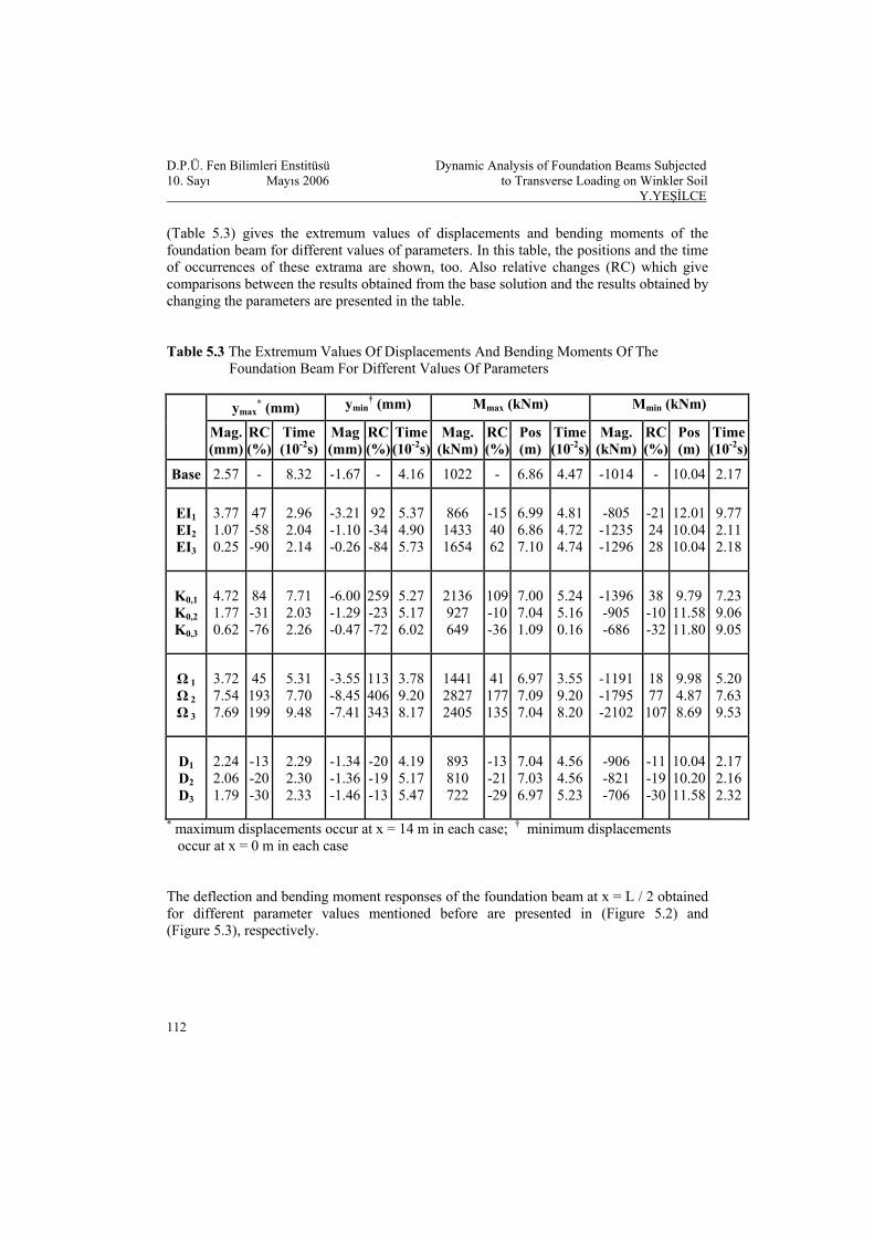
D.P.Ü. Fen Bilimleri Enstitüsü Dynamic Analysis of Foundation Beams Subjected 10. Sayı Mayıs 2006 to Transverse Loading on Winkler Soil Y.YEŞİLCE (Table 5.3) gives the extremum values of displacements and bending moments of the foundation beam for different values of parameters. In this table, the positions and the time of occurrences of these extrama are shown, too. Also relative changes (RC) which give comparisons between the results obtained from the base solution and the results obtained by changing the parameters are presented in the table. Table 5.3 The Extremum Values Of Displacements And Bending Moments Of The Foundation Beam For Different Values Of Parameters
ymax* (mm) ymin
† (mm) Mmax (kNm) Mmin (kNm)
Mag. (mm)
RC(%)
Time (10-2s)
Mag (mm)
RC(%)
Time(10-2s)
Mag. (kNm)
RC(%)
Pos (m)
Time(10-2s)
Mag. (kNm)
RC (%)
Pos (m)
Time(10-2s)
Base 2.57 - 8.32 -1.67 - 4.16 1022 - 6.86 4.47 -1014 - 10.04 2.17
EI1 EI2 EI3
3.77 1.07 0.25
47-58-90
2.96 2.04 2.14
-3.21 -1.10 -0.26
92-34-84
5.374.905.73
866 1433 1654
-154062
6.996.867.10
4.814.724.74
-805 -1235 -1296
-21 24 28
12.01 10.04 10.04
9.772.112.18
K0,1 K0,2 K0,3
4.72 1.77 0.62
84-31-76
7.71 2.03 2.26
-6.00 -1.29 -0.47
259-23-72
5.275.176.02
2136 927 649
109-10-36
7.007.041.09
5.245.160.16
-1396 -905 -686
38 -10 -32
9.79 11.58 11.80
7.239.069.05
Ω 1 Ω 2 Ω 3
3.72 7.54 7.69
45193199
5.31 7.70 9.48
-3.55 -8.45 -7.41
113406343
3.789.208.17
1441 2827 2405
41177135
6.977.097.04
3.559.208.20
-1191 -1795 -2102
18 77 107
9.98 4.87 8.69
5.207.639.53
D1 D2 D3
2.24 2.06 1.79
-13-20-30
2.29 2.30 2.33
-1.34 -1.36 -1.46
-20-19-13
4.195.175.47
893 810 722
-13-21-29
7.047.036.97
4.564.565.23
-906 -821 -706
-11 -19 -30
10.04 10.20 11.58
2.172.162.32
* maximum displacements occur at x = 14 m in each case; † minimum displacements occur at x = 0 m in each case The deflection and bending moment responses of the foundation beam at x = L / 2 obtained for different parameter values mentioned before are presented in (Figure 5.2) and (Figure 5.3), respectively.
112

D.P.Ü. Fen Bilimleri Enstitüsü Dynamic Analysis of Foundation Beams Subjected 10. Sayı Mayıs 2006 to Transverse Loading on Winkler Soil Y.YEŞİLCE
-1.5
-1
-0.5
0
0.5
1
1.5
2
2.5
3
0 0.02 0.04 0.06 0.08 0.1
Time (s)
Def
lect
ion
(mm
)
Base EIEI EI2 3
1
-3
-2
-1
0
1
2
3
4
0 0.02 0.04 0.06 0.08 0.1
Time (s)
Def
lect
ion
(mm
)
Base KK K2
1 3
(a) (b)
-6
-4
-2
0
2
4
6
0 0.02 0.04 0.06 0.08 0.1
Time (s)
Def
lect
ion
(mm
)
Base ΩΩ Ω2 3
1
-1.5
-1
-0.5
0
0.5
1
1.5
0 0.02 0.04 0.06 0.08 0.1
Time (s)
Def
lect
ion
(mm
)
Base DD D2
1
3
(c) (d)
Figure 5.2 Deflection versus time of the beam shown in (Figure 1.1) at x = L / 2 for different parameters:
113
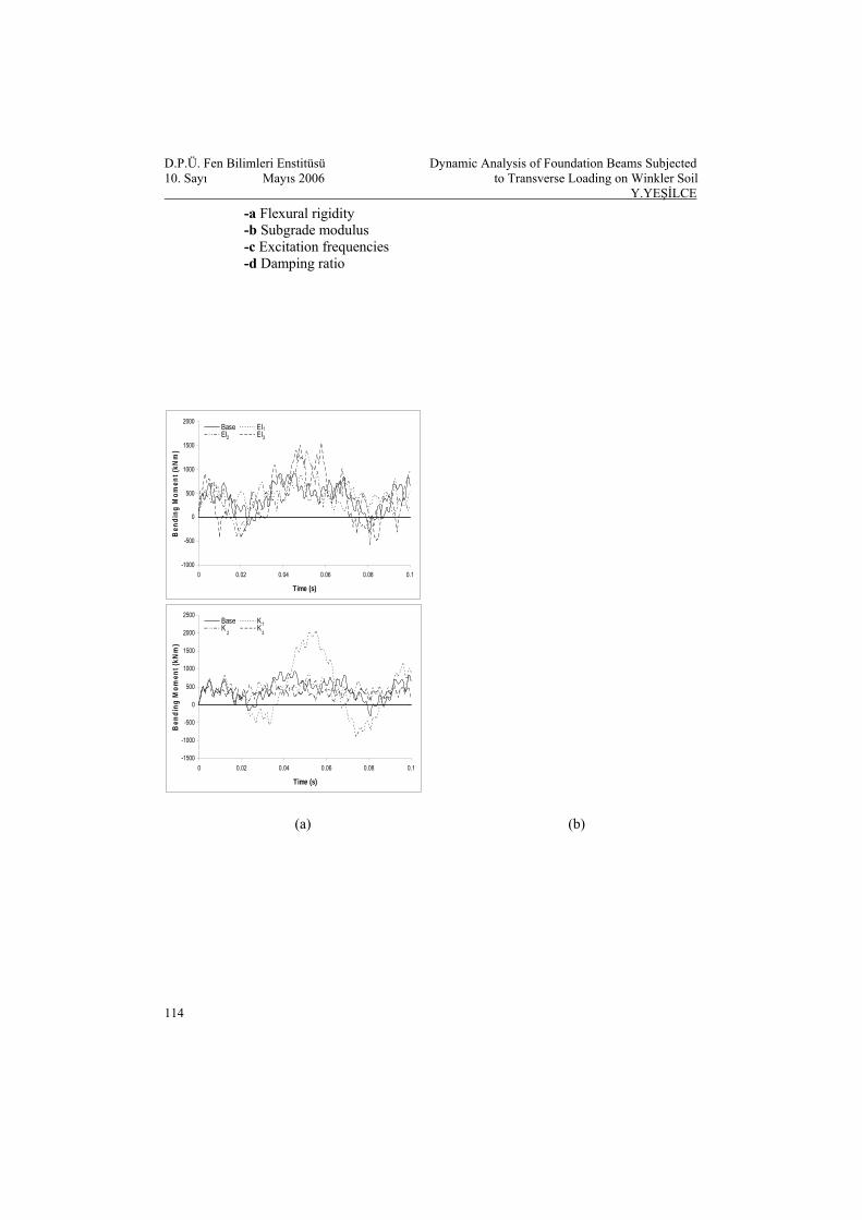
D.P.Ü. Fen Bilimleri Enstitüsü Dynamic Analysis of Foundation Beams Subjected 10. Sayı Mayıs 2006 to Transverse Loading on Winkler Soil Y.YEŞİLCE -a Flexural rigidity -b Subgrade modulus -c Excitation frequencies -d Damping ratio
-1000
-500
0
500
1000
1500
2000
0 0.02 0.04 0.06 0.08 0.1
Time (s)
Ben
ding
Mom
ent (
kNm
)
Base EIEI EI2
1
3
-1500
-1000
-500
0
500
1000
1500
2000
2500
0 0.02 0.04 0.06 0.08 0.1
Time (s)
Ben
ding
Mom
ent (
kNm
)
Base KK K
2
1
3
(a) (b)
114

D.P.Ü. Fen Bilimleri Enstitüsü Dynamic Analysis of Foundation Beams Subjected 10. Sayı Mayıs 2006 to Transverse Loading on Winkler Soil Y.YEŞİLCE
115
-2000
-1500
-1000
-500
0
500
1000
1500
2000
2500
3000
3500
0 0.02 0.04 0.06 0.08 0.1
Time (s)
Ben
ding
Mom
ent (
kNm
)
Base ΩΩ Ω2 3
1
-400
-200
0
200
400
600
800
1000
0 0.02 0.04 0.06 0.08 0.1
Time (s)
Ben
ding
Mom
ent (
kNm
)
Base DD D
2 13
(c) (d) Figure 5.3 Bending moment versus time of the beam shown in (Figure 1.1) at x = L / 2 for
different parameters: -a Flexural rigidity -b Subgrade modulus -c Excitation frequencies -d Damping ratio (Figure 5.4) shows the elastic curves of the beam at the time in which the maximum positive deflection occurs for different parameter values. The instances given in (Figure 5.4) can also be seen in (Table 5.3)
-2
-1
0
1
2
3
4
5
0 2 4 6 8 10 12 1
Position (m)
Def
lect
ion
(mm
)
4
Base (t=0.0832 s) EI (t=0.0296 s)EI (t=0.0204 s) EI (t=0.0214 s)
3 1
2
-3
-2
-1
0
1
2
3
4
5
6
0 2 4 6 8 10 12 1
Position (m)
Def
lect
ion
(mm
)
4
Base (t=0.0832 s) K (t=0.0771 s)K (t=0.0203 s) K (t=0.0226 s)
2 1 3
(a) (b)
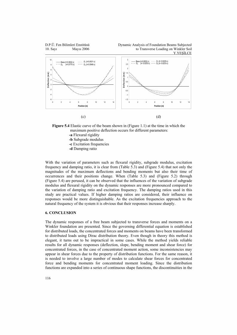
D.P.Ü. Fen Bilimleri Enstitüsü Dynamic Analysis of Foundation Beams Subjected 10. Sayı Mayıs 2006 to Transverse Loading on Winkler Soil Y.YEŞİLCE
116
-6
-4
-2
0
2
4
6
8
10
0 2 4 6 8 10 12 1
Position (m)
Def
lect
ion
(mm
)
4
Base (t=0.0832 s) Ω1 (t=0.0531 s)Ω3 (t=0.0948 s)Ω2 (t=0.0770 s)
-1.5
-1
-0.5
0
0.5
1
1.5
2
2.5
3
0 2 4 6 8 10 12 1
Position (m)
Def
lect
ion
(mm
)
4
Base (t=0.0832 s) D1 (t= 0.0229 s)D3 (t= 0.0233 s)D2 (t= 0.0230 s)
(c) (d)
Figure 5.4 Elastic curve of the beam shown in (Figure 1.1) at the time in which the maximum positive deflection occurs for different parameters: -a Flexural rigidity -b Subgrade modulus -c Excitation frequencies -d Damping ratio With the variation of parameters such as flexural rigidity, subgrade modulus, excitation frequency and damping ratio, it is clear from (Table 5.3) and (Figure 5.4) that not only the magnitudes of the maximum deflections and bending moments but also their time of occurrences and their positions change. When (Table 5.3) and (Figure 5.2) through (Figure 5.4) are perused, it can be observed that the influences of the variation of subgrade modulus and flexural rigidity on the dynamic responses are more pronounced compared to the variation of damping ratio and excitation frequency. The damping ratios used in this study are practical values. If higher damping ratios are considered, their influence on responses would be more distinguishable. As the excitation frequencies approach to the natural frequency of the system it is obvious that their responses increase sharply. 6. CONCLUSION The dynamic responses of a free beam subjected to transverse forces and moments on a Winkler foundation are presented. Since the governing differential equation is established for distributed loads, the concentrated forces and moments on beams have been transformed to distributed loads using Dirac distribution theory. Even though in theory this method is elegant, it turns out to be impractical in some cases. While the method yields reliable results for all dynamic responses (deflection, slope, bending moment and shear force) for concentrated forces, in the case of concentrated moment action, some inconsistencies may appear in shear forces due to the property of distribution functions. For the same reason, it is needed to involve a large number of modes to calculate shear forces for concentrated force and bending moments for concentrated moment loading. Since the distribution functions are expanded into a series of continuous shape functions, the discontinuities in the

D.P.Ü. Fen Bilimleri Enstitüsü Dynamic Analysis of Foundation Beams Subjected 10. Sayı Mayıs 2006 to Transverse Loading on Winkler Soil Y.YEŞİLCE related internal forces at the points of application of the loads can be noticed only when higher modes are used. REFERENCES
[1] J. Arsac, Fourier transforms and the theory of distributions, Prentice-Hall, Inc.,
Englewood Cliffs, N.J., (1966). [2] A.T. Daloglu and C.V.G. Vallabhan, Values of k for slab on Winkler foundation, Journal
of Geotechnical and Geoenvironmental Engineering, ASCE, 126 (2000), 463-473. [3] M.M. Filonenko-Borodich, Some approximate theories of elastic foundation (in
Russian), Uchenyie Zapiski Moskovskogo Gosudarstvennogo Universitet, Mekhanika, 46 (1946), 3-18.
[4] M. Hetenyi, Beams on elastic foundation, The University of Michigan Press, (1946). [5] A.D. Kerr, Elastic and visco-elastic foundations models, Journal of Applied
Mechanics, ASME, 31 (1964), 491-498. [6] P.L. Pasternak, On a new method of analysis of an elastic foundation by means of
two foundations constants (in Russian), Gasudarstvennoe Izdatelstvo Literaturi po Stroitelstvui Arkhitekure, Moscow, (1954).
[7] K. Terzaghi, Theoretical soil mechanics, 14th ed., John Wiley & Sons, Inc., New York,
(1966). [8] V.Z. Vlasov and N. N. Leontiev, Beams, plates and shells on elastic foundations (in
Russian), Fizmatgiz Publishers, Moscow, (1960). [9] E. Winkler, Die Lehre von der Elastizität und Festigkeit, Prag., (1867).
117