dynamic analysis of bridgegirder bridge subjected …
TRANSCRIPT

© 2019 JETIR January 2019, Volume 6, Issue 1 www.jetir.org (ISSN-2349-5162)
JETIR1901A61 Journal of Emerging Technologies and Innovative Research (JETIR) www.jetir.org 488
DYNAMIC ANALYSIS OF BRIDGEGIRDER
BRIDGE SUBJECTED TO BHUJ EARTHQUAKE
Dr. Uttam Kalwane1, Mr.Sushil Arunappa Naikwade2
Professor, P.G. Student
Civil Engineering Department,
Shreeyas College of Engineering and Technology Aurangabad
Abstract:Now days the dynamic performance of structure is very much essential while designing any structure. Analyzing the
PSC Box girder bridge, statically and dynamically is the basic aim of this dissertation. Here with and without application of
dynamic loads, the performance of bridge is studied. The study of bridge with bearing between girder and top of pier are included.
By applying moving load, vehicle (or) truck load, pre-stress and axial forces, the effects of bridge model is carefully studied.
Determining the actual seismic demand of bridge depends on the behavior of these model and also the importance of bearing
between girder and top of pier is taken into consideration. Box girder bridges can have a considerable effect on the behavior of the
bridge especially in the short to medium range of span such as 30m, 40m and 50m. In our project we study the behavior of box
girder bridges with respect to support reaction shear force, bending moment, torsion and axial force under standard IRC Class AA
loading and the box girder bridges models analyzed by finite element method.
Keywords- PSC Girder Bridge, time history analysis, ANSYS
I. INTRODUCTION
1. Introduction:-
The use of continuous concrete box girder bridges has increased recently. In construction of this type bridges having constant or
variable section height, the cantilever method can be applied. Box girder section forms consist of single or more box girder based
on bridge wide. The cantilever method is considered as the natural and logical solution in construction of box girder bridges.
There are two basic alternatives in the cantilever method: one is single cantilever method and the other is the double cantilever
method. In the former, the side span girders of the bridge are constructed on interim piers and afterwards the stiffening girder in
main span is constructed by one-sided free cantilevering until the span centre or the anchor pier on the far end is reached. In the
latter, the bridge girder is constructed from both side of the tower towards the anchor piers and the main span centre by double-
sided free cantilevering. The double cantilever method is also called as the balanced cantilever method. The method is especially
recommended where scaffolding is difficult or impossible to construct over deep valleys, wide rivers or in case of expensive
foundation conditions for scaffolds. In this method, bridges are built from one or more piers by means of formwork carriers.
Normally the structure advances from a short stub on top of a pier symmetrically in segments of about 3–6 m length to the mid
span or to an abutment, respectively. Each cantilevered part of the superstructure is tied to a previous one by concreting a key
segment and post-tensioning tendons. The pre stressing tendons are arranged based on the moment diagram of a cantilever.In
recent years, many interesting research topics have arisen such as to be taken in to account segmentally construction stages in the
analysis. Normally, structures are analysed by assuming that they are instantly built in a time. However, this type of analyses may
be give unreliable results which compared with those obtaining from that construction stage is considered. In the construction
stage analysis, time dependent material properties should be taken into account. Several studies have dealt with the analysis of
segmentally constructed bridges, as long as a few studies have been struggled the analysis of the deflection and internal moment
redistribution in bridges. Abbas and Scorelessachieved nonlinear geometric,material and time dependent analysis of segmentally
erected three-dimensional cable stayed bridges. Prestresed concrete bridges have found wide applications in railway engineering
in recent years. Because of being chronically exposed to the natural environment, they are vulnerable to cracking under heavy
trains, seismic excitation, and other loads. When the bridges are subjected to the independent action of static loads, especially
prestressing forces, the cracks may be closed. However, if large dynamic loads, such as heavy trains, are present, the cracks will
open and close in time depending on the structural vibration amplitude. Various studies over the last decade have shown that a
structure with such cracks exhibits nonlinear dynamic behaviour, and its safety and serviceability are seriously affected. So it is
essential to study the vibration of the Prestresed concrete bridge with such cracks under moving trains. In recent years, the
vibration of cracked structures subjected to dynamic loads has attracted more and more attentions of researchers, and many
methods for analysing the vibration were proposed. Generally, these methods can be grossly divided into two kinds according to
crack models used. The first kind is the modal method for the structure with switching cracks, which are either fully open or fully
closed and can switch their state instantaneously, showing a bilinear behaviour. The switching condition is assumed to be
determined by the sign of the normal strain, the displacement, or the curvature near the crack tip. When the crack is fully open, it
may seriously affect the local stiffness and response of the beam. Its effect can be modelled by means of a rotational spring model
or a crack disturbance function. The overall behaviour of the structure can be considered as a sequence of linear states, each of
which can be evaluated through a modal analysis. Through the modal method, The second kind of method is mainly concerned
with the structure with breathing cracks, for which there is a smooth transition phase between open and closed crack states. So the
cracks can open and close continuously, and the crack state is assumed to be dependent on the responses, such as the contact
condition at the crack interfaces, the time, or the curvature. As the structural stiffness can vary with the crack state, it will change

© 2019 JETIR January 2019, Volume 6, Issue 1 www.jetir.org (ISSN-2349-5162)
JETIR1901A61 Journal of Emerging Technologies and Innovative Research (JETIR) www.jetir.org 489
gradually during the vibration, and the structural behaviour will exhibit obvious nonlinearity.The main objective of the nonlinear
analysis is to analysis the different properties of the material and structure beyond the elastic limit and before the collapse. This is
based on to take the advantage of ductility and strength beyond the elastic limit by which the cost of the construction can be cut
because the strength of beyond the elastic limit are also considered. Concurring to Caltrans, ordinary spans will be not outlined to
react flexibly amid theMaximum Earthquake in light of the fact that of financial requirements and the vulnerabilities in
anticipating seismic requests. In this way, the objective will be to take advantage of pliabilityand post versatile quality to meet the
madeexecution criteria with a least capital venture.Such logic is constructing with respect to thegenerally low likelihood that a
major tremor will happen at a given site and the readiness to ingest the repair cost at if ever a major seismic tremor happens. The
purpose of the present work is to carry out a seismic evaluation of an already constructed river bridges using the nonlinear static
analysis and compare it with the nonlinear dynamic analysis result. This work is performed with the help of open sees software.
The Hindon river bridge is 3 span continuous bridges which is pre stressed box – girder type and its tendons are tensioned. Its
total length is m114.9m, and the height of its bents is 8o5 m and 866m. The model of the bridge is required for the mnonlinear
study of this bridge. The most effected part of the RC bridges is the column during the seismic activities of earth.Due to efficient
dissemination of congested traffic, economic considerations, and aesthetic desirability horizontally box girder bridges have
become increasingly popular nowadays in modern highway systems, including urban interchanges. Currently curved girders have
replaced straight segments because in urban areas where elevated highways and multi-level structures are necessary, modern
highway bridges are often subjected to severe geometric restrictions. The cost of the superstructure for the girder is higher, the
total cost of the curved girder system is reduced considerably since the number of intermediate supports, expansion joints and
bearing details is reduced. The continuous girder also provides more aesthetically pleasing structures. Despite all the advantages
mentioned above, horizontally curved girders are generally more complex than straight girders. Girders are subjected to vertical
bending plus torsion caused by the girder curvature. To deal with such complexities, several approximate analysis methods were
developed in the sixties. In the past, curved girders were generally composed of a series of straight segments that were used as
chords in forming a curved alignment.The use of Prestresed concrete components has been accepted for many years for structures
under gravity loading. The applications of the material are increasing rapidly, encouraged by such advantages as the possibility of
pleasing architectural forms, and the suitability of Prestresed concrete to modern prefabricated construction. However the use of
Prestresed concrete in primary seismic resistant elements such as shear walls and frames has created considerable controversy.
This review is a historical trace of the approach of design and research engineers to the suitability or otherwise of prestressed
concrete for earthquake resistance. It discusses such fundamental properties as stiffness, damping, energy absorption and
dissipation, and ductility, all of which will affect the response and hence the structural behaviour of prestressed concrete buildings
under earthquake loading.Traditionally, blast resistant design strategies have been reserved for military and government buildings,
or forconsideration of accidental explosions in chemical facilities. However, with recent worldwide events, many engineers are
now incorporating anti-terrorism measures into the design of a much wider variety of structures. Highway bridges require special
consideration because the condition of transportation infrastructure can significantly affect the economy. The loss of a critical
bridge could result in economic damage not only on a local level, but possibly on a national or global level. Prestressed concrete
girders are commonly used for highway bridges. In Washington, nearly 3000 of the state-owned bridges are of this construction
type, representing nearly 40 percent of the bridges in the state. Across the nation, approximately 11 percent of all highway bridges
are supported with prestressed concrete girders. However, very little research has been done to evaluate the blast performance of
prestressed concrete members or the bridges they support. The overall goals of the work described here were to develop and
evaluate modelling techniques for simulating the behaviour of precast, prestressed concrete girders subjected to blast loading and
to apply those techniques to characterize the blast response of typical bridges constructed of those girders.
2. Description of Example Bridge:-
The Budan Bridge, shown in Fig. 1, is a reinforced continuous concrete box girder type bridge located on between Artvinand
Erzurum highway, Turkey, at 55 + 729.00–56 + 079.00 km. Construction of the bridge started in 2007 and completed recently.
The configuration of the bridge is a three-span, cast-in-place concrete box girder superstructure supported on reinforced concrete
piers. The bridge deck consists of a main span of 165.00 m and two side spans of 92.50 m each. The total bridge length is 350.00
m and width of bridge is 15.00 m. The structural system of the bridge consists of a continuous deck, two piers, two abutments and
a closure segment. The piers have the heights of 91.77 m at the 55 + 821.50 km and of 97.17 mat the 55 + 986.50 km. The cross-
sections of the piers and the deck are given in detail in Fig. 2. The cross-section of the deck
Fig1.1: The Budan Bridge and its dimensions.

© 2019 JETIR January 2019, Volume 6, Issue 1 www.jetir.org (ISSN-2349-5162)
JETIR1901A61 Journal of Emerging Technologies and Innovative Research (JETIR) www.jetir.org 490
Fig1.2: Cross-sections of (a) piers and (b) deck of the Budan Bridge.
Consists of a single cell box girder with cantilevered slabs. The girder depth varies from a maximum of 9.50 m over the piers to a
minimum of 2.50 m at the mid span and abutments. The closure segment in the middle of the central span is 1.50 m long. The
bottom slab thickness is variable, as well. In order to investigate the construction stage response effects on the Budan Bridge,
three-dimensional finite element model is used. The primary objective of this study is to perform a parametrical study associated
with the construction stages and its effects on the response of continuous concrete box girder bridges. However, soil–structure
interaction is not considered.
3. Types of girder:-
There are basically two types of cross sections currently being in used for alignment: an open section consisting of a number of I-
shaped cross sections braced with a heavy transverse bracing system and the other type of section is a closed section consisting of
few box girders. Compared to I-beam girders, box girders have a number of key advantages and disadvantages. In addition to the
large torsional stiffness, box girders provide higher corrosion resistance because a high percentage of the steel surface including
the top of the bottom flange is not subjected to the environmental attack. The box girder also has a smooth shape that leads to
better bridge aesthetics. The trapezoidal shape, which is more popular nowadays, offers several advantages over rectangular
shaped cross section. The trapezoidal box girder (bath-tub girder) provides a narrow bottom flange. Near the abutments where the
bending moment is low, narrow flanges allow for steel savings.
Fig1.3: Types of girder
Box girder bridges are very commonly having its main beams comprising of girders in the shape of hollow boxes. The box girder
normally comprises of pre-stressed concrete, structural steel or steel reinforced concrete. As shown in Figure, a box girder cross
section may take the form of single cell(one box), multiple spine (separate boxes), or multicellular with a common bottom flange
(continuous cells). The box girder bridge achieves its stability mainly because of two key features: shape and
Prestresedtendons.At fabrication and erection stages, the section may be completely open at the top or it may be braced by a top
lateral bracing system to the top flanges. To close the top opening and complete the box, a reinforced concrete deck slab is added
which acts compositely with the steel section by a means of shear connectors.
4. Objectives and scope:-
The current study is about the behaviour and analysis investigation of the box girder bridges. The objectives and scope for the
study are:
1. Develop three-dimensional finite element models of box girders using the commercially available finite element computer
program "ANSYS".
2. Study the behaviour of box girders and compare the analytical model results and finally the description of the models of the
girder bridges is presented.
3.To study effect of span and various cross sections of girders subjected various specified ground motion

© 2019 JETIR January 2019, Volume 6, Issue 1 www.jetir.org (ISSN-2349-5162)
JETIR1901A61 Journal of Emerging Technologies and Innovative Research (JETIR) www.jetir.org 491
II. LITERATURE REVIEW
III METHODOLOGY
Fig 1: Flow chart of methodology
3.1 LOADS ON PRESTRESS GIRDER
The following are the various loads to be considered for the purpose of analysis.
1) Dead load
2) Live load
3) Impact load
4) Seismic load
3.1.1 DEAD LOAD
It is a gravity loading due to the structure simply calculated as the product of volume of bridge and material density of the bridge.
3.1.2 LIVE LOAD
Road bridge decks have to be designed to withstand the live loads specified by Indian Roads Congress (I.R.C: 6-2010 Section II)
In India, highway bridges are designed in accordance with IRC bridge code. IRC: 6 - 2010 – Section II gives the
specifications for the various loads and stresses to be considered in bridge design. There are three types of standard loadings for
which the bridges are designed namely, IRC class AA loading, IRC class A loading and IRC class B loading.
Fig 3.1 IRC Class AA loading
IRC class AA loading consists of either a tracked vehicle of 70 tonnes or a wheeled vehicle of 40 tonnes with dimensions
as shown in Fig.3.1. The units in the figure are mm for length and tonnes for load. Normally, bridges on national highways and
state highways are designed for these loadings. Bridges designed for class AA loading should be checked for IRC class A loading
also, since under certain conditions, larger stresses may be obtained under class A loading. Sometimes class 70 R can be used for
IRC class AA loading. Class 70R loading is not discussed further here.

© 2019 JETIR January 2019, Volume 6, Issue 1 www.jetir.org (ISSN-2349-5162)
JETIR1901A61 Journal of Emerging Technologies and Innovative Research (JETIR) www.jetir.org 492
Fig 3.2 IRC Class A loading
Fig 3.3 IRC Class B loading
Class A loading shown in Fig 3.2 consists of a wheel load train composed of a driving vehicle and two trailers of
specified axle spacing. This loading is normally adopted on all roads on which permanent bridges are constructed. Class B
loading shown in Fig 3.3 is adopted for temporary structures and for bridges in specified areas.
3.1.3 IMPACT LOAD
The dynamic effect caused due to vertical oscillation and periodical shifting of the live load from one wheel to another when
the locomotive is moving is known as impact load. The impact load is determined as a product of impact factor (i) and the live
load.
Fig 3.4: Impact percentage curve for highway bridges for IRC class A and IRC class B loadings.
The impact factors for different bridges for different types of moving loads are given in the Table 3.1 as shown below.
3.1.4. SEISMIC LOAD
If a bridge is situated in an earthquake prone region, the earthquake or seismic forces are given due consideration in the analysis.
An earthquake causes vertical and horizontal forces in the structure that will be proportional to the weight of the structure. IS:
1893 Part-3 may be referred for the actual design loads.
The following methods of seismic analysis can be employed for calculation of seismic forces in bridges.
1) Seismic Coefficient Method (SCM)
2) Response Spectrum Method (RSM)
3) Time History Method (THM)

© 2019 JETIR January 2019, Volume 6, Issue 1 www.jetir.org (ISSN-2349-5162)
JETIR1901A61 Journal of Emerging Technologies and Innovative Research (JETIR) www.jetir.org 493
4) Pushover Analysis (PA)
Seismic Coefficient Method (SCM)
The seismic force to be resisted by bridge component shall be computed as follows:
F = Ah W
Where
F = Horizontal seismic force to be resisted
W = Weight under consideration ignoring reduction due to buoyancy or uplift.
Ah = Design horizontal seismic coefficient
Response Spectrum Method (RSM)
The following steps are required in RSM:
a) Formulation of an appropriate mathematical model consisting of lumped mass system using 2D/3D beam elements.
The mathematical model should suitably represent dynamic characteristics of superstructure, bearings, substructure,
foundation and soil/rock springs. In rock and very stiff soil fixed base can be considered.
b) Determination of natural frequency and mode shapes following a standard stiffness matrix, transfer matrix or other
standard approach.
c) Determine total response by combining responses in various modes by (i) by mode combination procedure such as
SRSS, CQC, etc. or (ii) time-wise superposition of responses using ground motion time history(s). In method (i) Ah shall
be computed as explained in (d) below.
Fig 3.5 Average acceleration coefficient
d) Horizontal Seismic Coefficient (Ah)
The design horizontal seismic coefficient, Ah shall be determined from following expression of 6.4.2 of IS1893 (Part 1):
2002.
Provided that for any structure with T < 0.1 sec, the value of Ah will not be taken less than Z/2 whatever be the value of
I/R
Where,
Z = Zone factor
I = Importance factor, Table 3.2
R = Response reduction factor, Table 3.3
Sa/g = Average Acceleration coefficient for rock or soil sites as given in Fig.3.5.
o Importance Factor (I)
Bridges are designed to resist design basis earthquake (DBE) level, or other higher or lower magnitude of forces,
depending on the consequences of their partial or complete non-availability, due to damage or failure from seismic event.
The level of design force is obtained by multiplying (Z/2) by factor ‘I’, which represents seismic importance of the structure.

© 2019 JETIR January 2019, Volume 6, Issue 1 www.jetir.org (ISSN-2349-5162)
JETIR1901A61 Journal of Emerging Technologies and Innovative Research (JETIR) www.jetir.org 494
a) Extent of disturbance to traffic and possibility of providing temporary diversion,
b) Availability of alternative routes,
c) Cost of repairs and time involved, which depend on the extent of damages, -minor or major.
d) Cost of replacement, and time involved in reconstruction in case of failure.
e) Indirect economic loss due to its partial or full non-availability
Importance factors are given in Table 3.2 for different types of bridges.
o Response Reduction Factor (R)
The Response Reduction Factor for different components is given in Table 3.3
Response Reduction Factors (R)
Superstructure, reinforced concrete 3.0
Superstructure, steel, pre stressed concrete 2.5
Substructure
a) Reinforced concrete piers with ductile detailing cantilever
type, wall type 3.0
b) Reinforced concrete piers without ductile detailing,
cantilever type, wall type
2.5
c) Masonry piers (un reinforced) cantilever type, wall type 1.5
d) Reinforced concrete, framed construction in piers, with
ductile detailing, columns of RCC bents, RCC single column
piers
4.0
e) Steel framed construction 2.5
f) Steel cantilever piers 1.0
g) Steel trussed arch 1.5
h) Reinforced concrete arch 3.5
k) Abutments of mass concrete and masonry 1.0
m) R.C.C. abutment 2.5
n) Integral frame with ductile detailing 4.0
p) Integral frame without ductile detailing 3.3
Table 3.3 Response reduction factors (R)
Time History Method (THM)
The dynamic analysis of a bridge by time history method can be carried out using direct step-by-step method of
integration of equations of motion. At least three spectrum compatible time histories shall be used, when site-specific time
histories are not available. The spectrum used to generate these time histories shall be the same as used for the modal
analysis. Their duration shall be consistent with their magnitude and source characteristics of design basis earthquake. The
total duration of time history shall be about 30s of which the strong motion part shall be not less than 6s.This analysis can be
carried out using a standard software package.
Pushover Analysis (PA)
It is a static nonlinear analysis carried out to determine lateral load vs. displacement at control point in the structure for
the purpose of determining capacity of the structure. The analysis can be performed using a standard software package. The
method can be employed for design of special bridges and to determine capacity of existing structures for the purpose of
retrofitting.
2. LIVE LOAD COMBINATIONS
According to IRC 6-2010 Table 2, the different live loads combinations are considered for different carriageway width of bridges
are as given in Table 3.4
Sl.No Carriageway width Number of lanes for
design purposes Load Combination
1) Less than 5.3 m 1
One Lane of Class A considered to occupy
2.3m. The remaining width of carriageway
shall be loaded with 500 kg/m²
2)
5.m m and above but
less than 9.6 m 2 One lane of Class 70 R or two lanes of Class A
3) 9.6 m and above but less
than 13.1 m 3
One lane of Class 70 R for every two lanes
with one lane of Class A on the remaining or 3

© 2019 JETIR January 2019, Volume 6, Issue 1 www.jetir.org (ISSN-2349-5162)
JETIR1901A61 Journal of Emerging Technologies and Innovative Research (JETIR) www.jetir.org 495
lanes of Class A
4) 13.1 m and above but
less than 16.6 m 4
One lane of Class 70 R for every two lanes
with one lane of Class A for the remaining
lanes, if any or one lane of Class A for each
lane.
5) 16.6 m and above but
less than 20.1 m 5
6) 20.1 m and above but
less than 23.6 m 6
Table 3.4 Live load combinations
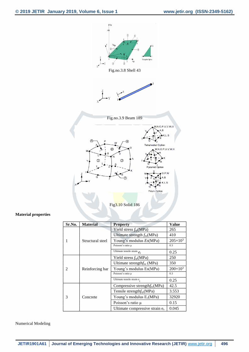
I. MATERIAL MODELING IN ANSYS
The definition of the proposed numerical model was made by using finite elements available in the ANSYS code default
library. SOLID186 is a higher order 3-D 20-node solid element that exhibits quadratic displacement behavior. The element is
defined by 20 nodes having three degrees of freedom per node: translations in the nodal x, y, and z directions. The element
supports plasticity, hyperelasticity, creep, stress stiffening, large deflection, and large strain capabilities. It also has mixed
formulation capability for simulating deformations of nearly incompressible elastoplastic materials, and fully incompressible
hyperelastic materials. The geometrical representation of is show in SOLID186 fig 22.
This SOLID186 3-D 20-node homogenous/layered structural solid were adopted to discretize the concrete slab, which are also
able to simulate cracking behavior of the concrete under tension (in three orthogonal directions) and crushing in compression, to
evaluate the material non-linearity and also to enable the inclusion of reinforcement (reinforcement bars scattered in the concrete
region). The element SHELL43 is defined by four nodes having six degrees of freedom at each node. The deformation shapes are
linear in both in-plane directions. The element allows for plasticity, creep, stress stiffening, large deflections, and large strain
capabilities the representation of the steel section was made by the SHELL 43 elements, which allow for the consideration of non-
linearity of the material and show linear deformation on the plane in which it is present. The modeling of the shear connectors
was done by the BEAM 189 elements, which allow for the configuration of the cross section, enable consideration of the non-
linearity of the material and include bending stresses as shown in fig 3.5. CONTA174 is used to represent contact and sliding
between 3-D "target" surfaces (TARGE170) and a deformable surface, defined by this element. The element is applicable to 3-D
structural and coupled field contact analyses. The geometrical representation of CONTA174 is show in fig 3.2. Contact pairs
couple general axisymmetric elements with standard 3-D elements. A node-to-surface contact element represents contact between
two surfaces by specifying one surface as a group of nodes. The geometrical representation of is show in TARGET 170 fig 19.
The TARGET 170 and C0NTA 174 elements were used to represent the contact slab-beam interface. These elements are able
to simulate the existence of pressure between them when there is contact, and separation between them when there is not. The two
material contacts also take into account friction and cohesion between the parties.
Fig.no.3.6 CONTA 174
Fig.no.3.7 TARGET 170
© 2019 JETIR January 2019, Volume 6, Issue 1 www.jetir.org (ISSN-2349-5162)
JETIR1901A61 Journal of Emerging Technologies and Innovative Research (JETIR) www.jetir.org 496
Fig.no.3.8 Shell 43
Fig.no.3.9 Beam 189
Fig3.10 Solid 186
Material properties
Sr.No. Material Property Value
1 Structural steel
Yield stress fsy(MPa) 265
Ultimate strength fsu(MPa) 410
Young’s modulus Es(MPa) 205×103 Poisson’s ratio µ 0.3 Ultimate tensile strain et 0.25
2 Reinforcing bar
Yield stress fsy(MPa) 250
Ultimate strengthfsu (MPa) 350
Young’s modulus Es(MPa) 200×103 Poisson’s ratio µ 0.3 Ultimate tensile strain e
t 0.25
3 Concrete
Compressive strengthfsc(MPa) 42.5
Tensile strengthfsy(MPa) 3.553
Young’s modulus Ec(MPa) 32920
Poisson’s ratio µ 0.15
Ultimate compressive strain es 0.045
Numerical Modeling
© 2019 JETIR January 2019, Volume 6, Issue 1 www.jetir.org (ISSN-2349-5162)
JETIR1901A61 Journal of Emerging Technologies and Innovative Research (JETIR) www.jetir.org 497
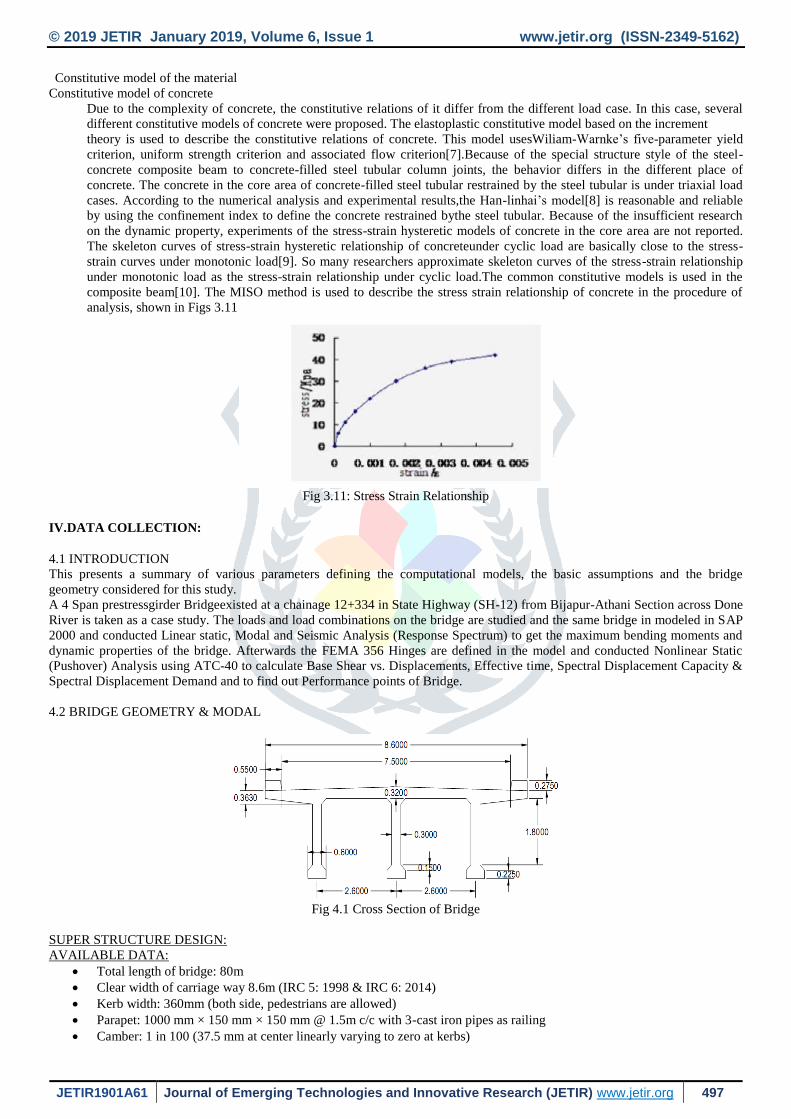
Constitutive model of the material
Constitutive model of concrete
Due to the complexity of concrete, the constitutive relations of it differ from the different load case. In this case, several
different constitutive models of concrete were proposed. The elastoplastic constitutive model based on the increment
theory is used to describe the constitutive relations of concrete. This model usesWiliam-Warnke’s five-parameter yield
criterion, uniform strength criterion and associated flow criterion[7].Because of the special structure style of the steel-
concrete composite beam to concrete-filled steel tubular column joints, the behavior differs in the different place of
concrete. The concrete in the core area of concrete-filled steel tubular restrained by the steel tubular is under triaxial load
cases. According to the numerical analysis and experimental results,the Han-linhai’s model[8] is reasonable and reliable
by using the confinement index to define the concrete restrained bythe steel tubular. Because of the insufficient research
on the dynamic property, experiments of the stress-strain hysteretic models of concrete in the core area are not reported.
The skeleton curves of stress-strain hysteretic relationship of concreteunder cyclic load are basically close to the stress-
strain curves under monotonic load[9]. So many researchers approximate skeleton curves of the stress-strain relationship
under monotonic load as the stress-strain relationship under cyclic load.The common constitutive models is used in the
composite beam[10]. The MISO method is used to describe the stress strain relationship of concrete in the procedure of
analysis, shown in Figs 3.11
Fig 3.11: Stress Strain Relationship
IV.DATA COLLECTION:
4.1 INTRODUCTION
This presents a summary of various parameters defining the computational models, the basic assumptions and the bridge
geometry considered for this study.
A 4 Span prestressgirder Bridgeexisted at a chainage 12+334 in State Highway (SH-12) from Bijapur-Athani Section across Done
River is taken as a case study. The loads and load combinations on the bridge are studied and the same bridge in modeled in SAP
2000 and conducted Linear static, Modal and Seismic Analysis (Response Spectrum) to get the maximum bending moments and
dynamic properties of the bridge. Afterwards the FEMA 356 Hinges are defined in the model and conducted Nonlinear Static
(Pushover) Analysis using ATC-40 to calculate Base Shear vs. Displacements, Effective time, Spectral Displacement Capacity &
Spectral Displacement Demand and to find out Performance points of Bridge.
4.2 BRIDGE GEOMETRY & MODAL
Fig 4.1 Cross Section of Bridge
SUPER STRUCTURE DESIGN:
AVAILABLE DATA:
Total length of bridge: 80m
Clear width of carriage way 8.6m (IRC 5: 1998 & IRC 6: 2014)
Kerb width: 360mm (both side, pedestrians are allowed)
Parapet: 1000 mm × 150 mm × 150 mm @ 1.5m c/c with 3-cast iron pipes as railing
Camber: 1 in 100 (37.5 mm at center linearly varying to zero at kerbs)

© 2019 JETIR January 2019, Volume 6, Issue 1 www.jetir.org (ISSN-2349-5162)
JETIR1901A61 Journal of Emerging Technologies and Innovative Research (JETIR) www.jetir.org 498
Wearing coat: 80mm
Kerb height above pavement: 200mm (insurmountable type)
Kerb type: full safety ensured
Total kerb height above deck slab: 320 mm
Clear depth of Longitudinal girders: 1800 mm
Width of longitudinal girder: 600mm
Deck slab thickness: 250 mm
Total overall depth of the super structure: 1800mm
c/c spacing of longitudinal girders: 2500 mm
clear distance of cantilever span from face of girder: 1800mm
Grade of concrete: M35
Design strength: fcd = 0.67fck/γmMPa (Annex – A2 of IRC 112: 2011)
Grade of steel : Fe415 (IS 1786 : 2000)
Design strength of steel : fy/1.15 = 0.87fy MPa (clause-15.2.3.3 of IRC 112:2011)
Poisson’s ratio: μ = 0.2 (Annex-B; B-3-1 of IRC 112:2011 )
Analysis of deck slab: Piegaud’s curve
DESIGN OF INTERIOR SLAB PANEL:
Bending Moment/Girder D.L Bending Moment L.L Bending Moment Total Bending Moment Unit
Outer Girder 2300 1760 4060 kN-m
Inner Girder 2300 1060 3360 kN-m
Shear Force/Girder D.L Shear L.L Shear Total Shear Unit
Outer Girder 489 410 899 kN
Inner Girder 489 410 899 kN
Table 4.1
4.3 INPUT DATA IN SAP 2000
Thedata is used in the analysis is given in Table 4.2.
Input Data for Analysis
Sl. No Particulars
1) Density of Reinforced Concrete 25 KN/m³
2) Grade of Concrete M-30
3) Type of live load IRC Class A Train
4)
Impact Factor (i)
0.173
5) Importance Factor (I) 1.2
6) Response Reduction Factor (R) 3.0
7) Poisson’s Ratio of Concrete 0.18
8) Seismic Zone Zone III
9) Seismic Zone Factor 0.16
10) Soil Type Type II
Table 4.2 Input Data in SAP 2000
V.RESULTS AND DISCUSSION
DATA COLLECTED

© 2019 JETIR January 2019, Volume 6, Issue 1 www.jetir.org (ISSN-2349-5162)
JETIR1901A61 Journal of Emerging Technologies and Innovative Research (JETIR) www.jetir.org 499
Graph 5.1: EL CENTRO
Idealization of above problem statement is modeled in finite element analysis tool ANSYS .Following models are prepared for
comparative analysis of bridge structure
MODEL NO.1 M30 80m span
MODEL NO.2 M30 40m span
Fig 5.1: Model
Fig 5.2: Total Deformation

© 2019 JETIR January 2019, Volume 6, Issue 1 www.jetir.org (ISSN-2349-5162)
JETIR1901A61 Journal of Emerging Technologies and Innovative Research (JETIR) www.jetir.org 500
The Equivalent Stress is 0.0037667 max
Fig 5.3: Equivalent Stress
The Equivalent Stress is 394.61 min
Fig 5.4:Time History Displacement
The Time HistoryDisplacementis maximum in m30 80m span

© 2019 JETIR January 2019, Volume 6, Issue 1 www.jetir.org (ISSN-2349-5162)
JETIR1901A61 Journal of Emerging Technologies and Innovative Research (JETIR) www.jetir.org 501
Fig 5.5: Time History Equivalent Stress
The Time HistoryEquivalent Stress is maximum in m30 80m span
Fig 5.6:Time HistoryEquivalent Stress
The Time HistoryEquivalent Stress is maximum in m30 80m span
VI.CONCLUSION
The present study emphasis on finding nonlinear stresses on structural element using ANSYS obtaining below results for time
history analysis
The normal stress ,bending stress and maximum principal stress observed 25-30% more in the 80m span model
VII.REFERENCES
1. “An Effective and Efficient Approach for Nonlinear Seismic Analysis of Bridges” By Y.Chen, June 1993.
2. “Application of pushover analysis on reinforced concrete bridge model” By Dr. Cosmin G. Chiorean, Research Report
No. POCTI/36019/99 July 2003.
3. “Effect of nonlinearity in pier and well foundation on seismic response of bridges” Submitted by GoutamMondal and
Sudhir K. Jain, in The 14th World Conference on Earthquake Engineering, October 12-17, 2008, Beijing, China.
4. “Non-Linear Finite Element Analysis for Assessment of Bridges” International Journal of Earth Science and
Engineering, Volume 2, No.06, December 2009.Submitted By : A.Kanchanadevi and C.Umarani
5. “Design of Bridges” By N.Krishnaraju, Fourth Edition, OXFORD & IHB Publishing Company in 2009.
6. “Analysis of T-beam Bridge Using Finite Element Method” International Journal of Engineering and Innovative
Technology (IJEIT) Volume 2, Issue 3, September 2012. Submitted By: R.Shreedhar&SpurtiMamadapur.

© 2019 JETIR January 2019, Volume 6, Issue 1 www.jetir.org (ISSN-2349-5162)
JETIR1901A61 Journal of Emerging Technologies and Innovative Research (JETIR) www.jetir.org 502
7. “Seismic Performance Study of Urban Bridges Using Nonlinear Static Analysis” International Journal of Innovative
Research in Science, Engineering and Technology Volume 2, Issue 6, June 2013. Submitted By: ParimalA.Godse.
8. “Nonlinear Analysis of Bridge Structures” Bridge Engineering Handbook.
9. “Structural Analysis in Earthquake Engineering – A Breakthrough of Simplified nonlinear methods” 12th European
Conference on Earthquake Engineering. Submitted By : P.Fajfar
10. “Seismic Performance Evaluation of Urban Bridge using Static Nonlinear Procedure, Case Study: Hafez Bridge” The
twelfth East Asia Pacific Conference on Structural Engineering and Construction. Submitted By: A. Nicknam, A.
Mosleh and H. HamidiJamnani.
11. “Essentials of Bridge Engineering” By D.Johnson Victor. Oxford and IBH Publshing company private limited.
12. IRC 6-2010 – Standard Specifications and code of practice for Road Bridges (Section II).
13. IS 1893 (Part 3) - Criteria for Earthquake resistant design of Structures - Bridges and Retaining walls.
14. IS 456 -2000 – Plain and Reinforced Concrete code of practice.
15. ATC 40 – Seismic evaluation and retrofit of concrete buildings.