dx100 upgrade procedure manual...manual no. hw0485126 2 part number: 161409-1cd revision: 1 dx100...
TRANSCRIPT
DX100UPGRADE PROCEDURE MANUAL
Upon receipt of the product and prior to initial operation, read these instructions thoroughly, and retain for future reference.
Part Number: 161409-1CDRevision: 1
MOTOMAN INSTRUCTIONS
MOTOMAN- INSTRUCTIONSDX100 INSTRUCTIONSDX100 OPERATOR’S MANUALDX100 MAINTENANCE MANUAL
The DX100 operator’s manual above corresponds to specific usage. Be sure to use the appropriate manual.
MANUAL NO.
2HW0485126 1/45

DX100
161409-1CD
MANDATORY
• This manual explains the upgrading procedures of the DX100 system. Read this manual carefully and be sure to understand its contents before handling the DX100.
• General items related to safety are listed in the Chapter 1: Safety of the DX100 Instructions. To ensure correct and safe operation, carefully read the DX100 Instructions before reading this manual.
CAUTION
• Some drawings in this manual are shown with the protective covers or shields removed for clarity. Be sure all covers and shields are replaced before operating this product.
• The drawings and photos in this manual are representative examples and differences may exist between them and the delivered product.
• YASKAWA may modify this model without notice when necessary due to product improvements, modifications, or changes in specifications. If such modification is made, the manual number will also be revised.
• If your copy of the manual is damaged or lost, contact a YASKAWA representative to order a new copy. The representatives are listed on the back cover. Be sure to tell the representative the manual number listed on the front cover.
• YASKAWA is not responsible for incidents arising from unauthorized modification of its products. Unauthorized modification voids your product’s warranty.
ii
HW0485126 2/45

DX100
161409-1CD
Notes for Safe OperationRead this manual carefully before installation, operation, maintenance, or inspection of the DX100.
In this manual, the Notes for Safe Operation are classified as “WARNING”, “CAUTION”, “MANDATORY”, or ”PROHIBITED”.
Even items described as “CAUTION” may result in a serious accident in some situations. At any rate, be sure to follow these important items.
WARNINGIndicates a potentially hazardous situation which, if not avoided, could result in death or serious injury to personnel.
CAUTIONIndicates a potentially hazardous situation which, if not avoided, could result in minor or moderate injury to personnel and damage to equipment. It may also be used to alert against unsafe practices.
MANDATORYAlways be sure to follow explicitly the items listed under this heading.
PROHIBITEDMust never be performed.
NOTETo ensure safe and efficient operation at all times, be sure to follow all instructions, even if not designated as “CAU-TION” and “WARNING”.
iii
HW0485126 3/45
DX100
161409-1CD
WARNING
• Before operating the manipulator, check that servo power is turned off when the emergency stop buttons on the front door of the DX 100 and programing pendant are pressed. When the servo power is turned off, the SERVO ON LED on the programing pendant is turned off.
Injury or damage to machinery may result if the emergency stop circuit cannot stop the manipulator during an emergency. The manipulator should not be used if the emergency stop buttons do not function.
Fig. : Emergency Stop Button
• Once the emergency stop button is released, clear the cell of all items which could interfere with the operation of the manipulator. Then turn the servo power ON.
Injury may result from unintentional or unexpected manipulator motion.
Fig. : Release of Emergency Stop
TURN
• Observe the following precautions when performing teaching operations within the P-point maximum envelope of the manipulator:
– View the manipulator from the front whenever possible.
– Always follow the predetermined operating procedure.
– Ensure that you have a safe place to retreat in case of emergency.
Improper or unintended manipulator operation may result in injury.
• Confirm that no person is present in the P-point maximum envelope of the manipulator and that you are in a safe location before:
– Turning on the power for the DX100.
– Moving the manipulator with the programming pendant.
– Running the system in the check mode.
– Performing automatic operations.
Injury may result if anyone enters the working envelope of the manipulator during operation. Always press an emergency stop button immediately if there are problems.
• The emergency stop button is located on the right of the front door of the DX 100 and programing pendant.
iv
HW0485126 4/45

DX100
161409-1CD
CAUTION
• Perform the following inspection procedures prior to conducting manipulator teaching. If problems are found, repair them immediately, and be sure that all other necessary processing has been performed.
– Check for problems in manipulator movement.
– Check for damage to insulation and sheathing of external wires.
• Always return the programming pendant to the hook on the cabinet of the DX100 after use.
The programming pendant can be damaged if it is left in the manipulator's work area, on the floor, or near fixtures.
• Read and understand the Explanation of Warning Labels in the DX100 Instructions before operating the manipulator.
v
HW0485126 5/45

DX100
161409-1CD
Descriptions of the programming pendant keys, buttons, and displays are shown as follows:
Description of the Operation ProcedureIn the explanation of the operation procedure, the expression "Select • • • " means that the cursor is moved to the object item and the SELECT key is pressed.
Registered TrademarkIn this manual, names of companies, corporations, or products are trademarks, registered trademarks, or brand names for each company or corporation. The indications of (R) and TM are omitted.
Equipment Manual Designation
Programming Pendant
Character Keys The keys which have characters printed on them are denoted with [ ].ex. [ENTER]
Symbol Keys The keys which have a symbol printed on them are not denoted with [ ] but depicted with a small picture.
ex. page key
The cursor key is an exception, and a picture is not shown.
Axis KeysNumeric Keys
“Axis Keys” and “Numeric Keys” are generic names for the keys for axis operation and number input.
Keys pressed simultaneously
When two keys are to be pressed simultaneously, the keys are shown with a “+” sign between them, ex. [SHIFT]+[COORD]
Displays The menu displayed in the programming pendant is denoted with { }.ex. {JOB}
PAGE
GO BACK
PAGE
GO BACK
vi
HW0485126 6/45
DX100 Table of Contents
vii
161409-1CD
HW0485126
1 Outline ............................................................................................................................................ 1-1
1.1 Outline of Upgrade Procedure ........................................................................................... 1-1
2 CompactFlash/USB Preparation..................................................................................................... 2-1
2.1 Prearrangements ............................................................................................................... 2-1
2.2 Preparing CompactFlash/USB for Upgrade....................................................................... 2-2
3 Data Back Up.................................................................................................................................. 3-1
3.1 Data Back Up..................................................................................................................... 3-1
3.2 Recording Other Information ............................................................................................. 3-5
3.3 Recording Information in Maintenance Mode .................................................................... 3-6
3.4 Procedures Ahead of Upgrading the System with Safety Function ................................... 3-8
4 System Software Upgrade.............................................................................................................. 4-1
4.1 System Software Upgrade................................................................................................. 4-1
4.1.1 Upgrade Using CompactFlash ............................................................................. 4-2
4.1.2 Upgrade Using USB ............................................................................................. 4-5
5 Programming Pendant Upgrade ..................................................................................................... 5-1
5.1 Programming Pendant Upgrade........................................................................................ 5-1
6 Data Rebuild Procedure in Maintenance Mode .............................................................................. 6-1
6.1 Data Rebuild Procedure in Maintenance Mode................................................................. 6-1
6.2 Procedures After Upgrading the System with Safety Function.......................................... 6-3
6.2.1 Safety Function Setting ........................................................................................ 6-3
6.2.2 Speed Reducer Life Diagnosis Relevant Data Loading ....................................... 6-4
7 Troubleshooting .............................................................................................................................. 7-1
7.1 Back Up the CompactFlash ............................................................................................... 7-1
7.2 How to Repair Programming Pendant when Fonts are Garbled ...................................... 7-4
7/45

1 OutlineDX100 1.1 Outline of Upgrade Procedure
1-1
161409-1CD
HW0485126
1 Outline
1.1 Outline of Upgrade Procedure
The upgrading procedures for the DX100 is outlined as follows:
Upgrading Start
Upgrade from DS1.xx-67 to DSx.xx-00 or
from DS1.xx-14 to DSx.xx-14
Upgrade from DS1.xx-67 to DSx.xx-00 or
from DS1.xx-14 to DSx.xx-14
“COASTING VALUE SETTING” window appears.Select {INVALID} if {VALID} is selected.
(Refer to Chapter 3.4)
Indicate “Safety function [Function setting]” window.Press {ENTER}.
(Refer to Chapter 6.2.1)
IF speed reducer life diagnosis function is used.
Load and verify “LIFEDIAG.DAT” and “RL.DCOND.CND”which are saved on the EXTERNAL MEMORY DEVICE window.
(Refer to Chapter 6.2.2)
CompactFlash/USB Preparation(Refer to Chapter 2)
Data Back Up(Refer to Chapter 3)
System Software Upgrade(Refer to Chapter 4)
Programming Pendant Upgrade(Refer to Chapter 5)
Upgrading Completed
Data Rebuild Procedure in Maintenance Mode(Refer to Chapter 6)
8/45

2 CompactFlash/USB PreparationDX100 2.1 Prearrangements
161409-1CD
2 CompactFlash/USB Preparation
To upgrade the DX100, it is required to set a CompactFlash memory card (hereinafter referred to as “CompactFlash”) or a USB memory stick (hereinafter referred to as “USB”) into the programming pendant.
This chapter describes on how to prepare the CompactFlash or USB for upgrading the DX100.
2.1 Prearrangements
Prepare the following items when making the CompactFlash/USB for the DX100 upgrade.
• Personal computer with Windows operating system, available to use CompactFlash/USB. (Windows is a registered trademark of Micro-soft Corporation.)
• Data file for upgrade.
• CompactFlash The following types are recommended for DX100.
<Recommended CompactFlash>
• USB The following type is recommended for DX100.
< Recommended USB Memory>
No. Manufacturer Model Remarks
1 Hagiwara Sys-Com MCF10P-256MS-YE2 256MB
2 Hagiwara Sys-Com MCF10P-512MS 512MB
3 Hagiwara Sys-Com MCF10P-A01GS 1GB
4 Hagiwara Sys-Com MCF10P-A02GS 2GB
5 SiliconSystems, Inc. SSD-CxxM-3512 “xx” represents the capacity (up to 2GB.)
No. Manufacturer Model Remarks
1 Hagiwara Sys-Com UDG3-GA series 1GB or 2GB
SUPPLE-MENT
The above mentioned CompactFlash with different capacity (xxMB) is also available to use.
2-1
HW0485126 9/45

2 CompactFlash/USB PreparationDX100 2.2 Preparing CompactFlash/USB for Upgrade
161409-1CD
2.2 Preparing CompactFlash/USB for Upgrade
Prepare the CompactFlash/USB for upgrade with a personal computer.
1. Select the subject file of upgrade.
– The figure below is an example in case where data exists in a CD.
2. Run "MK_VX_CF.EXE".
NOTE Be sure to delete all the data in the CompactFlash/USB before starting the operation.
2-2
HW0485126 10/45

2 CompactFlash/USB PreparationDX100 2.2 Preparing CompactFlash/USB for Upgrade
161409-1CD
3. Check if the "Source Version" is correct.
4. Select "VersionUp CF/USB".
2-3
HW0485126 11/45
2 CompactFlash/USB PreparationDX100 2.2 Preparing CompactFlash/USB for Upgrade
161409-1CD
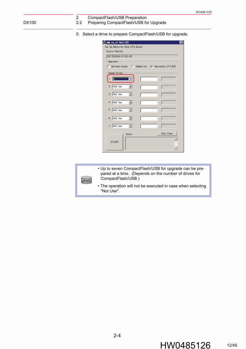
5. Select a drive to prepare CompactFlash/USB for upgrade.
SUPPLE-MENT
• Up to seven CompactFlash/USB for upgrade can be pre-pared at a time. (Depends on the number of drives for CompactFlash/USB.)
• The operation will not be executed in case when selecting "Not Use".
2-4
HW0485126 12/45
2 CompactFlash/USB PreparationDX100 2.2 Preparing CompactFlash/USB for Upgrade
161409-1CD
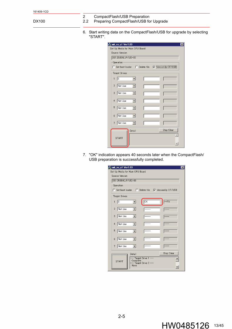
6. Start writing data on the CompactFlash/USB for upgrade by selecting "START".
7. "OK" indication appears 40 seconds later when the CompactFlash/USB preparation is successfully completed.
2-5
HW0485126 13/45
2 CompactFlash/USB PreparationDX100 2.2 Preparing CompactFlash/USB for Upgrade
161409-1CD
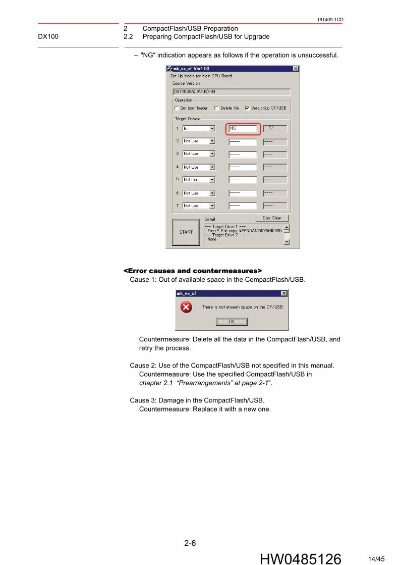
– "NG" indication appears as follows if the operation is unsuccessful.
<Error causes and countermeasures>Cause 1: Out of available space in the CompactFlash/USB.
Countermeasure: Delete all the data in the CompactFlash/USB, and retry the process.
Cause 2: Use of the CompactFlash/USB not specified in this manual. Countermeasure: Use the specified CompactFlash/USB in chapter 2.1 “Prearrangements” at page 2-1".
Cause 3: Damage in the CompactFlash/USB. Countermeasure: Replace it with a new one.
2-6
HW0485126 14/45

3 Data Back UpDX100 3.1 Data Back Up
161409-1CD
3 Data Back Up
Perform the following operation in advance so that the data can be restored if upgrading is unsuccessful.
3.1 Data Back Up
Back up the data which is required for setting up the data after the upgrade in the following procedures:
1. Check if the main power of the DX100 is turned OFF.
2. Insert the CompactFlash/USB prepared in chapter 2.2 “Preparing CompactFlash/USB for Upgrade” at page 2-2 into the programming pendant.
– When inserting the CompactFlash, open the CF slot cover. Pay attention to insert the CompactFlash in the correct direction. After that, close the CF slot cover.
– When inserting the USB, remove the rubber cap on the USB slot on the back of the programming pendant.
CF slot
Example of CF
front surface
Example of CF
back surface
Example of CF
front surface
Example of CF
back surface
USB slot
USB
3-1
HW0485126 15/45
3 Data Back UpDX100 3.1 Data Back Up
161409-1CD
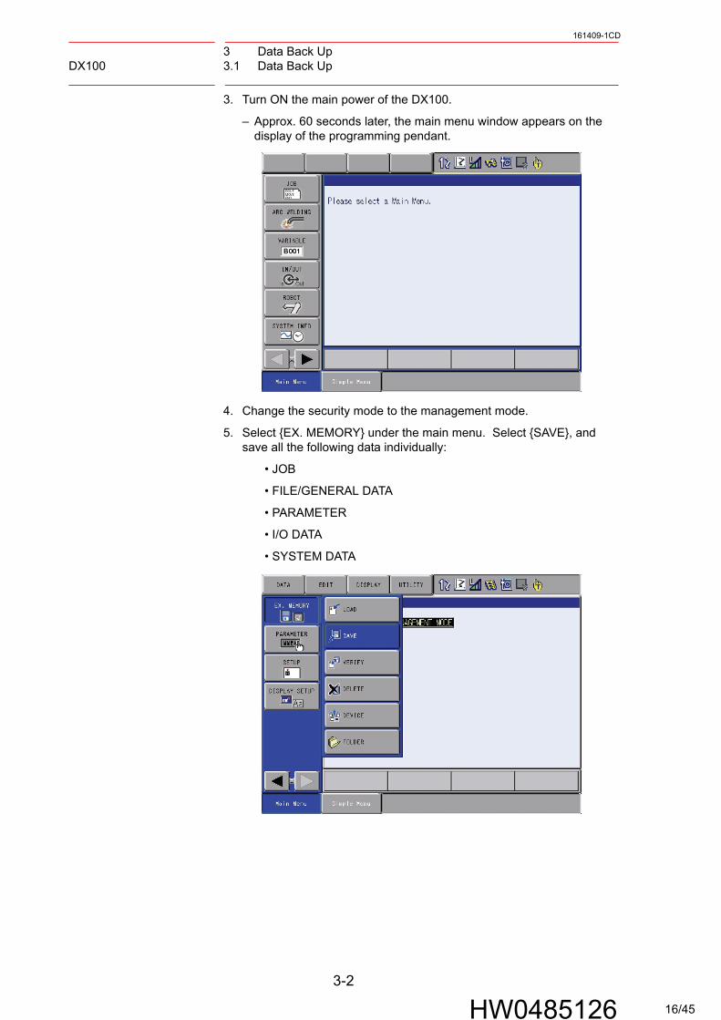
3. Turn ON the main power of the DX100.
– Approx. 60 seconds later, the main menu window appears on the display of the programming pendant.
4. Change the security mode to the management mode.
5. Select {EX. MEMORY} under the main menu. Select {SAVE}, and save all the following data individually:
• JOB
• FILE/GENERAL DATA
• PARAMETER
• I/O DATA
• SYSTEM DATA
3-2
HW0485126 16/45

3 Data Back UpDX100 3.1 Data Back Up
161409-1CD
6. Move the cursor to {JOB} and press [SELECT].
7. Select {EDIT}, then select {SELECT ALL}.
8. When the job is selected, it will be indicated with "" mark. Press [ENTER] when all the jobs are selected.
3-3
HW0485126 17/45

3 Data Back UpDX100 3.1 Data Back Up
161409-1CD
9. Select {YES} to start the data saving.
10. Each job data is saved individually when the figure on the display changed as shown below.
11. Save the other data individually in the same way.
SUPPLE-MENT
Select [STOP] to stop saving the data.
In this case, the window will return to the {JOB LIST} on the step 7.
3-4
HW0485126 18/45

3 Data Back UpDX100 3.2 Recording Other Information
161409-1CD
3.2 Recording Other Information
The information listed below should be recorded individually because the data are not saved in the CompactFlash/USB.
1. Common
• MASTER JOB
• KEY ALLOCATION
• GROUP COMBINATION
• USER ID
• REGISTER SETTING
2. For Motor Gun Application
• Since the weld diagnosis data are not saved, record the information in {WELD DIAGNOSIS} under {SPOT WELDING}.
3-5
HW0485126 19/45

3 Data Back UpDX100 3.3 Recording Information in Maintenance Mode
161409-1CD
3.3 Recording Information in Maintenance Mode
1. Turn ON the power supply of the DX100 while pressing [MAIN MENU] simultaneously.
2. Approx. 60 seconds later, the top window of the maintenance mode appears on the display of the programming pendant.
3. Select {SETUP} under the {SYSTEM}, then save the following data:
• LANGUAGE
• CONTROL GROUP (Data of axes configurations, data set for exter-nal axis motor, SERVOPACK, etc.)
• APPLICATION
• OPTION BOARD (Detailed settings of expansion boards, etc.)
• OPTION FUNCTION (Detailed settings of optional functions, etc.)
[MAIN MENU] key
3-6
HW0485126 20/45

3 Data Back UpDX100 3.3 Recording Information in Maintenance Mode
161409-1CD
4. Select {EX. MEMORY}, then select {Save}. Select {CMOS} to save the binary file "CMOS.BIN".
5. Turn OFF the main power of the DX100 after the CMOS save is completed.
3-7
HW0485126 21/45

3 Data Back UpDX100 3.4 Procedures Ahead of Upgrading the System with Safety Function
161409-1CD
3.4 Procedures Ahead of Upgrading the System with Safety
Function
Following operations are required when upgrading the version from:
• DS1.xx-67 to DSx.xx-00 (DS3.00-00 or later)or
• DS1.xx-14 to DSx.xx-14 (DS3.00-14 or later)
1. Select {ROBOT}, then {COASTING VALUE SETTING} in the security mode of Maintenance mode or higher.No action is required if {COASTING VALUE SETTING} is not shown.
2. Select {INVALID} if {VALID} is selected to {IMMEDIATE STOP}.No action is required if {INVALID} is already selected.
3-8
HW0485126 22/45
4 System Software UpgradeDX100 4.1 System Software Upgrade
161409-1CD
4 System Software Upgrade
4.1 System Software Upgrade
Upgrade the system software following the procedures below. The upgrade is performed using either the CompactFlash or USB. If both the CompactFlash and USB are inserted in the programming pendant, the upgrade is performed using the CompactFlash.
4-1
HW0485126 23/45
4 System Software UpgradeDX100 4.1 System Software Upgrade
161409-1CD
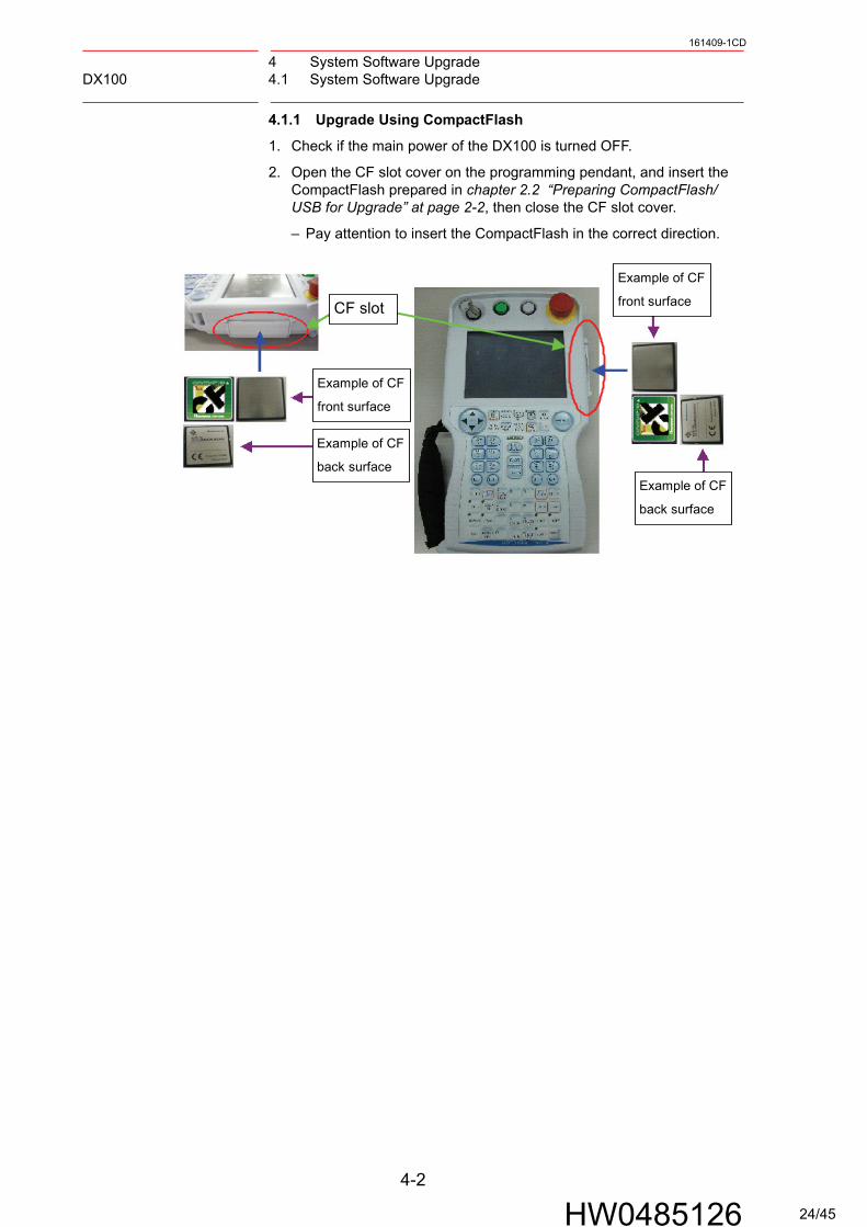
4.1.1 Upgrade Using CompactFlash
1. Check if the main power of the DX100 is turned OFF.
2. Open the CF slot cover on the programming pendant, and insert the CompactFlash prepared in chapter 2.2 “Preparing CompactFlash/USB for Upgrade” at page 2-2, then close the CF slot cover.
– Pay attention to insert the CompactFlash in the correct direction.
CF slot
Example of CF
front surface
Example of CF
back surface
Example of CF
front surface
Example of CF
back surface
4-2
HW0485126 24/45
4 System Software UpgradeDX100 4.1 System Software Upgrade
161409-1CD
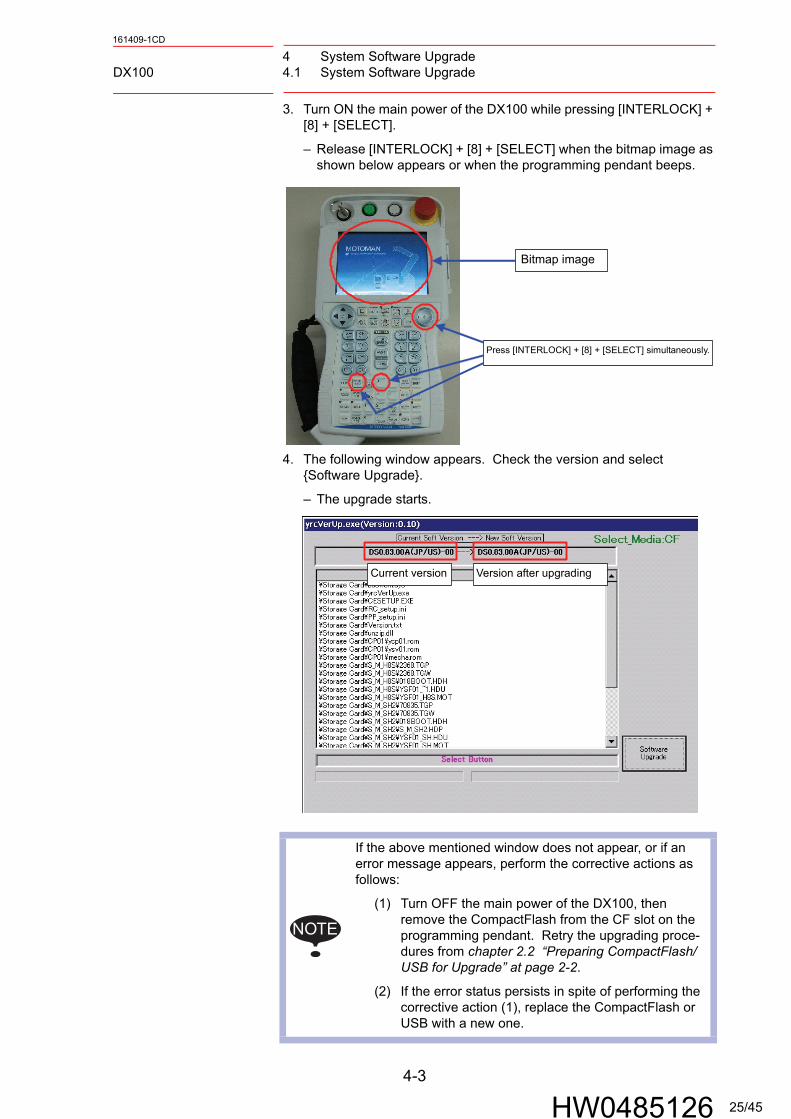
3. Turn ON the main power of the DX100 while pressing [INTERLOCK] + [8] + [SELECT].
– Release [INTERLOCK] + [8] + [SELECT] when the bitmap image as shown below appears or when the programming pendant beeps.
4. The following window appears. Check the version and select {Software Upgrade}.
– The upgrade starts.
Press [INTERLOCK] + [8] + [SELECT] simultaneously.
Bitmap image
NOTE
If the above mentioned window does not appear, or if an error message appears, perform the corrective actions as follows:
(1) Turn OFF the main power of the DX100, then remove the CompactFlash from the CF slot on the programming pendant. Retry the upgrading proce-dures from chapter 2.2 “Preparing CompactFlash/USB for Upgrade” at page 2-2.
(2) If the error status persists in spite of performing the corrective action (1), replace the CompactFlash or USB with a new one.
Current version Version after upgrading
4-3
HW0485126 25/45

4 System Software UpgradeDX100 4.1 System Software Upgrade
161409-1CD
– During the upgrade, the “HOLD” button of the programming pendant lights, the message “Upgrade Executing” blinks, and the upgrade progress bar and the name of the file being upgraded are shown.
5. When the message “Turn off controller power supply” appears, turn OFF the main power of the DX100.
Displays the progress of the
upgrade operation on the
DX100 side, and the name of
the file being upgraded.
Displays the progress of the upgrade
operation on the programming
pendant side, and the name of the
file being upgraded.
4-4
HW0485126 26/45

4 System Software UpgradeDX100 4.1 System Software Upgrade
161409-1CD
4.1.2 Upgrade Using USB
1. Check if the main power of the DX100 is turned OFF.
2. Remove the rubber cap on the back of the programming pendant, and insert the USB prepared in chapter 2.2 “Preparing CompactFlash/USB for Upgrade” at page 2-2.
3. Turn ON the main power of the DX100 while pressing [INTERLOCK] + [8] + [SELECT].
– Release [INTERLOCK] + [8] + [SELECT] when the bitmap image as shown below appears or when the programming pendant beeps.
USB slot
USB
Press [INTERLOCK] + [8] + [SELECT] simultaneously.
Bitmap image
4-5
HW0485126 27/45

4 System Software UpgradeDX100 4.1 System Software Upgrade
161409-1CD
4. The following window appears. Check the version and select {Software Upgrade}.
– The upgrade starts.
NOTE
If the above mentioned window does not appear, or if an error message appears, perform the corrective actions as follows:
(1) Turn OFF the main power of the DX100, then remove the USB from the USB slot on the program-ming pendant. Retry the upgrading procedures from chapter 2.2 “Preparing CompactFlash/USB for Upgrade” at page 2-2.
(2) If the error status persists in spite of performing the corrective action (1), replace the USB with a new one.
Current version Version after upgrading
4-6
HW0485126 28/45
4 System Software UpgradeDX100 4.1 System Software Upgrade
161409-1CD
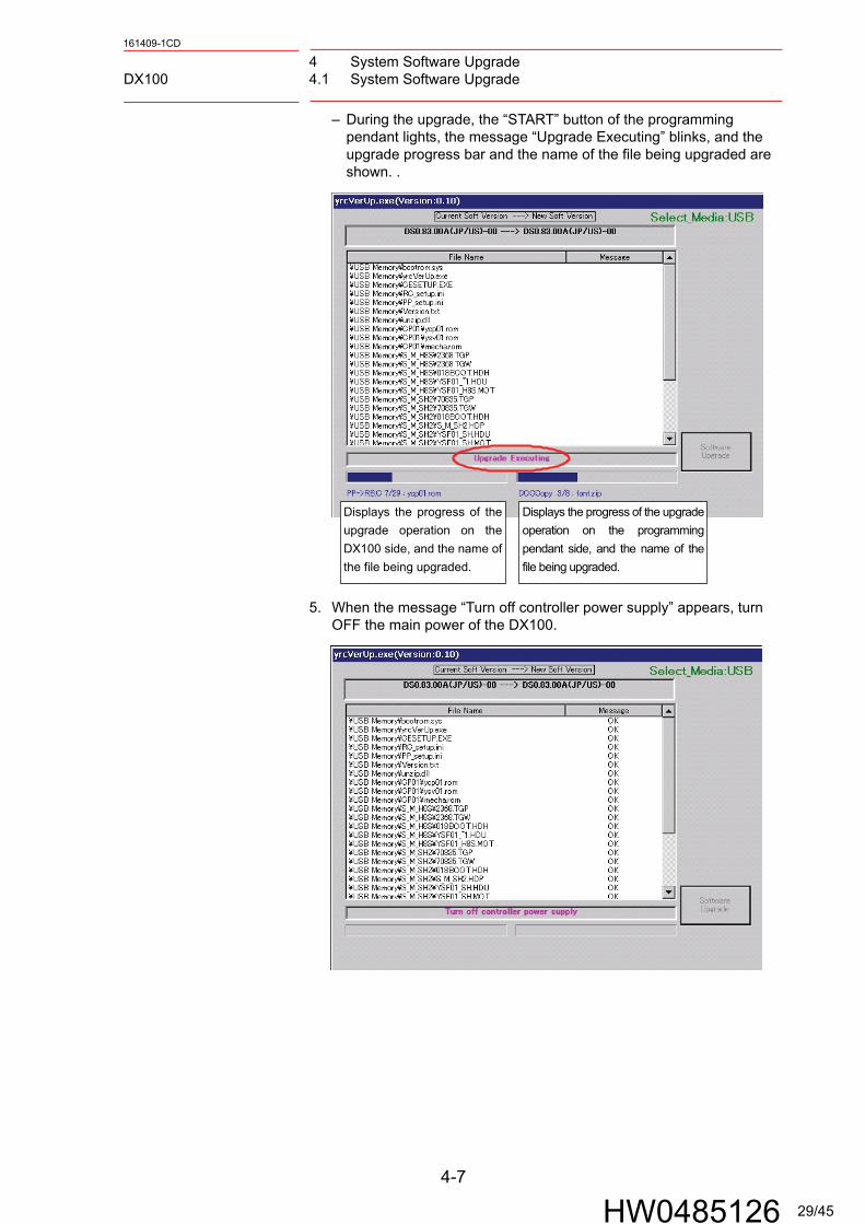
– During the upgrade, the “START” button of the programming pendant lights, the message “Upgrade Executing” blinks, and the upgrade progress bar and the name of the file being upgraded are shown. .
5. When the message “Turn off controller power supply” appears, turn OFF the main power of the DX100.
Displays the progress of the
upgrade operation on the
DX100 side, and the name of
the file being upgraded.
Displays the progress of the upgrade
operation on the programming
pendant side, and the name of the
file being upgraded.
4-7
HW0485126 29/45
5 Programming Pendant UpgradeDX100 5.1 Programming Pendant Upgrade
161409-1CD
5 Programming Pendant Upgrade
This operation is not necessary when performing a normal upgrade.
Additional information will be provided if this operation is required.
5.1 Programming Pendant Upgrade
Upgrade the system software following the procedures below:
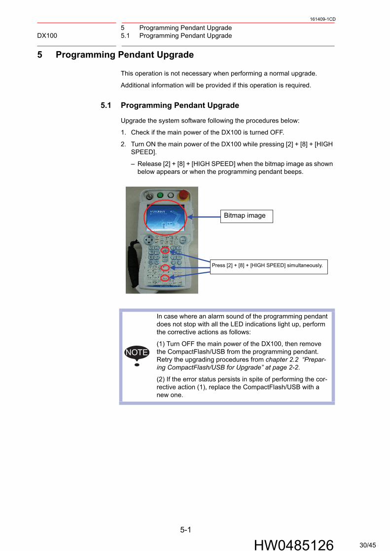
1. Check if the main power of the DX100 is turned OFF.
2. Turn ON the main power of the DX100 while pressing [2] + [8] + [HIGH SPEED].
– Release [2] + [8] + [HIGH SPEED] when the bitmap image as shown below appears or when the programming pendant beeps.
Bitmap image
Press [2] + [8] + [HIGH SPEED] simultaneously.
NOTE
In case where an alarm sound of the programming pendant does not stop with all the LED indications light up, perform the corrective actions as follows:
(1) Turn OFF the main power of the DX100, then remove the CompactFlash/USB from the programming pendant. Retry the upgrading procedures from chapter 2.2 “Prepar-ing CompactFlash/USB for Upgrade” at page 2-2.
(2) If the error status persists in spite of performing the cor-rective action (1), replace the CompactFlash/USB with a new one.
5-1
HW0485126 30/45

5 Programming Pendant UpgradeDX100 5.1 Programming Pendant Upgrade
161409-1CD
– NK.BIN (OS: Windows CE) in the CompactFlash is written into SDRAM first; the NK.BIN (in the SDRAM) then be written into FlashRom of the programming pendant. The LED indications during the process change as described below:
3. The touch panel calibration appears on the display of the programming pendant approx. 7 minutes after turning ON the main power of the DX100.
– Press the center of the display panel with a stylus for touch panel for approx. 2 seconds to perform the touch calibration. If a stylus for touch panel is not available, use a pointed tool with a soft point, such as a ballpoint pen cap, as a substitute.
(When reading NK.BIN fromCompactFlash to SDRAM)
(When writing NK.BIN fromSDRAM to FlashRom)
Data reading from CompactFlash to SDRAM: 4 LED indications blink clockwise. The blink interval is irregular. (The interval may be 1 to 2 seconds or 4 to 5 seconds.) The time required for reading is approx. 3 minutes.
Data writing from SDRAM to FlashRom: 3 LED indications blink clockwise. The blink interval is 1 to 2 seconds. The time required for writing is approx. 4 minutes.
SUPPLE-MENT
The total time required for data transfer and writing from CompactFlash to FlashRom is approx. 7 minutes.
5-2
HW0485126 31/45
5 Programming Pendant UpgradeDX100 5.1 Programming Pendant Upgrade
161409-1CD
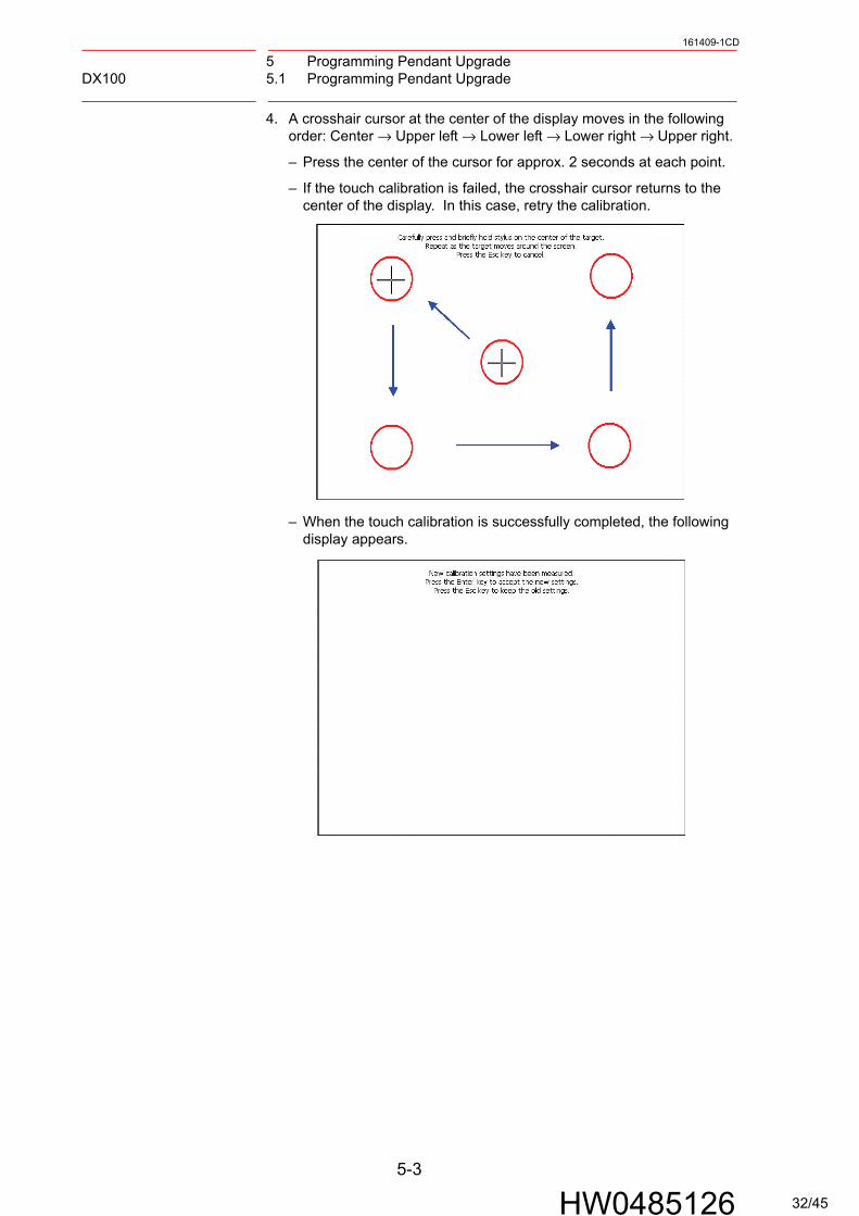
4. A crosshair cursor at the center of the display moves in the following order: Center → Upper left → Lower left → Lower right → Upper right.
– Press the center of the cursor for approx. 2 seconds at each point.
– If the touch calibration is failed, the crosshair cursor returns to the center of the display. In this case, retry the calibration.
– When the touch calibration is successfully completed, the following display appears.
5-3
HW0485126 32/45
5 Programming Pendant UpgradeDX100 5.1 Programming Pendant Upgrade
161409-1CD
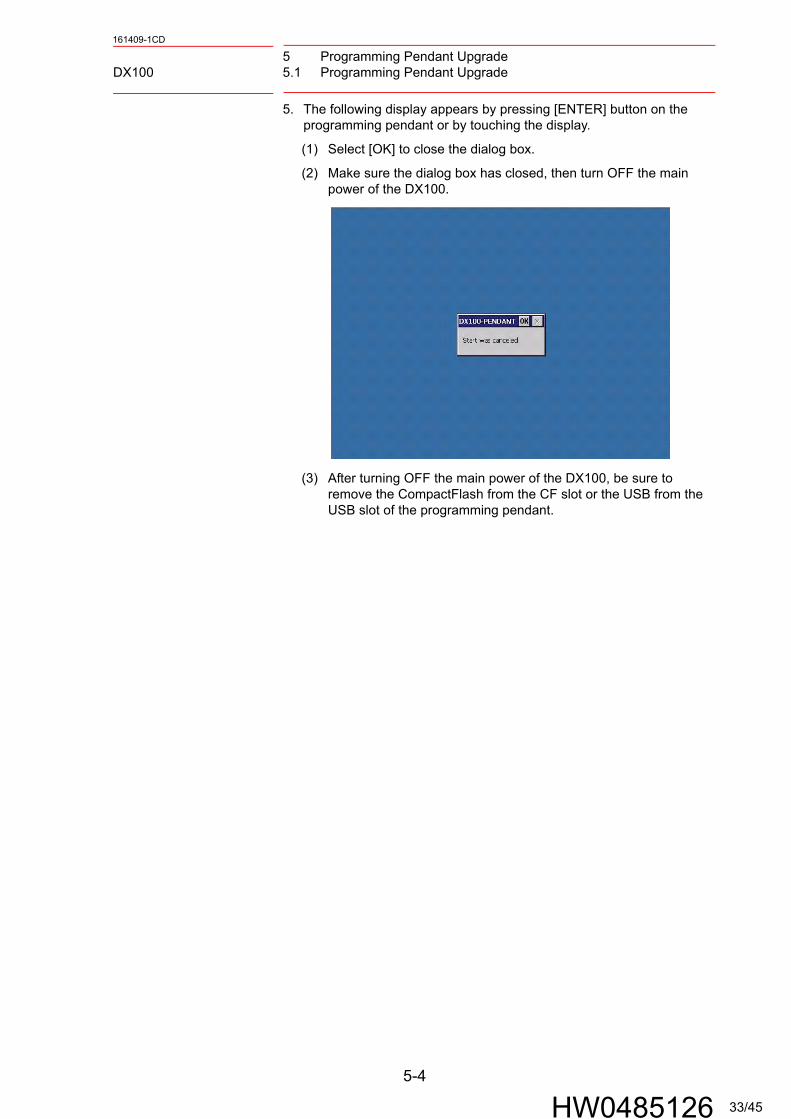
5. The following display appears by pressing [ENTER] button on the programming pendant or by touching the display.
(1) Select [OK] to close the dialog box.
(2) Make sure the dialog box has closed, then turn OFF the main power of the DX100.
(3) After turning OFF the main power of the DX100, be sure to remove the CompactFlash from the CF slot or the USB from the USB slot of the programming pendant.
5-4
HW0485126 33/45

5 Programming Pendant UpgradeDX100 5.1 Programming Pendant Upgrade
161409-1CD
6. Turn ON the main power of the DX100.
– The main menu window appears approx. 60 seconds later.
7. Select {SYSTEM INFO} and then {VERSION} under the main menu to confirm the version data.
5-5
HW0485126 34/45

6 Data Rebuild Procedure in Maintenance ModeDX100 6.1 Data Rebuild Procedure in Maintenance Mode
161409-1CD
6 Data Rebuild Procedure in Maintenance Mode
Following alarms occur if there is a difference in the CMOS data before and after the upgrade.
For these alarms, follow the corrective instructions below.
6.1 Data Rebuild Procedure in Maintenance Mode
1. Select {SYSTEM} then {DATA REBUILD} in management mode in maintenance mode.
6-1
HW0485126 35/45
6 Data Rebuild Procedure in Maintenance ModeDX100 6.1 Data Rebuild Procedure in Maintenance Mode
161409-1CD
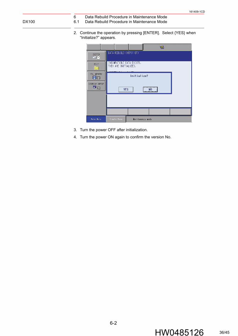
2. Continue the operation by pressing [ENTER]. Select {YES} when “Initialize?” appears.
3. Turn the power OFF after initialization.
4. Turn the power ON again to confirm the version No.
6-2
HW0485126 36/45
6 Data Rebuild Procedure in Maintenance ModeDX100 6.2 Procedures After Upgrading the System with Safety Function
161409-1CD
6.2 Procedures After Upgrading the System with Safety
Function
Following operations are required after upgrading the version from:
• DS1.xx-67 to DSx.xx-00 (DS3.00-00 or later)or
• DS1.xx-14 to DSx.xx-14 (DS3.00-14 or later)
6.2.1 Safety Function Setting
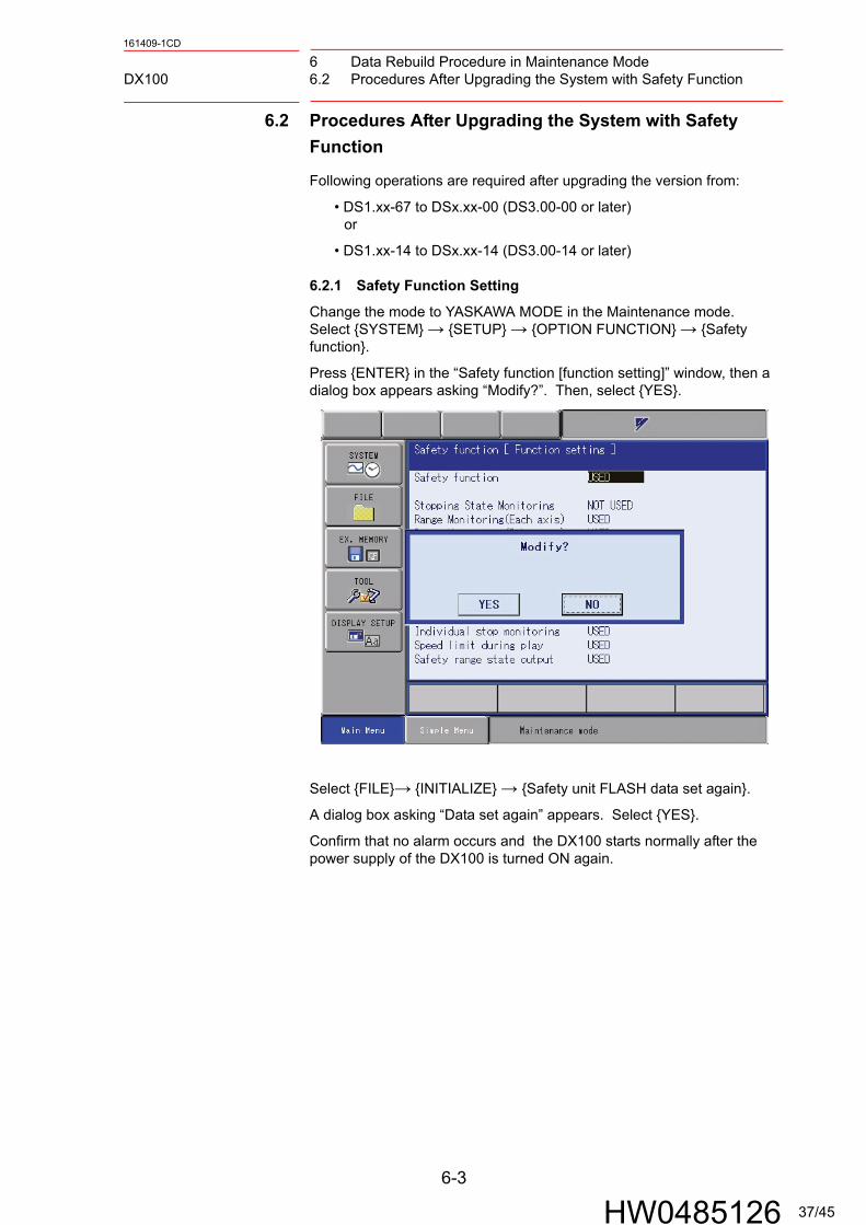
Change the mode to YASKAWA MODE in the Maintenance mode.Select {SYSTEM} → {SETUP} → {OPTION FUNCTION} → {Safety function}.
Press {ENTER} in the “Safety function [function setting]” window, then a dialog box appears asking “Modify?”. Then, select {YES}.
Select {FILE}→ {INITIALIZE} → {Safety unit FLASH data set again}.
A dialog box asking “Data set again” appears. Select {YES}.
Confirm that no alarm occurs and the DX100 starts normally after the power supply of the DX100 is turned ON again.
6-3
HW0485126 37/45
6 Data Rebuild Procedure in Maintenance ModeDX100 6.2 Procedures After Upgrading the System with Safety Function
161409-1CD
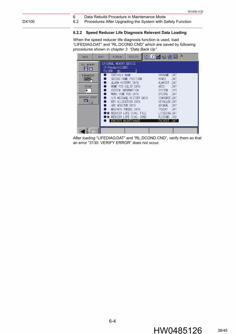
6.2.2 Speed Reducer Life Diagnosis Relevant Data Loading
When the speed reducer life diagnosis function is used, load “LIFEDIAG.DAT” and “RL.DCOND.CND” which are saved by following procedures shown in chapter 3 “Data Back Up” .
After loading “LIFEDIAG.DAT” and “RL.DCOND.CND”, verify them so that an error “3130: VERIFY ERROR” does not occur.
6-4
HW0485126 38/45
7 TroubleshootingDX100 7.1 Back Up the CompactFlash
161409-1CD
7 Troubleshooting
Perform the following operation if the DX100 does not start up normally or does not operate correctly.
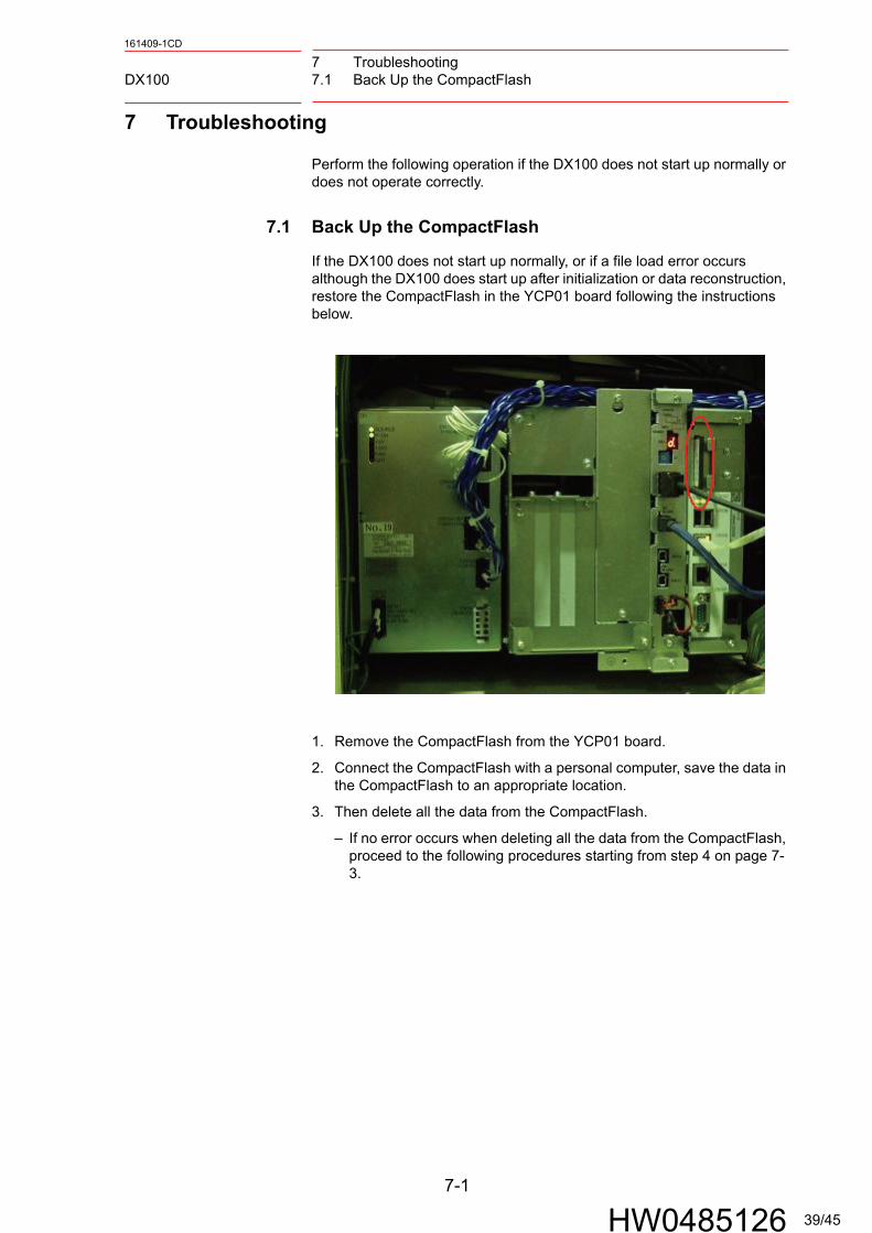
7.1 Back Up the CompactFlash
If the DX100 does not start up normally, or if a file load error occurs although the DX100 does start up after initialization or data reconstruction, restore the CompactFlash in the YCP01 board following the instructions below.
1. Remove the CompactFlash from the YCP01 board.
2. Connect the CompactFlash with a personal computer, save the data in the CompactFlash to an appropriate location.
3. Then delete all the data from the CompactFlash.
– If no error occurs when deleting all the data from the CompactFlash, proceed to the following procedures starting from step 4 on page 7-3.
7-1
HW0485126 39/45

7 TroubleshootingDX100 7.1 Back Up the CompactFlash
161409-1CD
– If an error occurs at this point, follow the procedure below.
(1) Right-click on the removable disk drive where the CompactFlash is inserted, and click [Properties].
(2) Then, click the [Tools] tab and click "Check Now" in the [Error-checking] box.
(3) Tick the check boxes in the [Check disk options] and click [Start].
7-2
HW0485126 40/45

7 TroubleshootingDX100 7.1 Back Up the CompactFlash
161409-1CD
4. Perform the same operations as described in chapter 2.2 “Preparing CompactFlash/USB for Upgrade” at page 2-2. At this time, do not check any item in the “Operation” box, and just click [START].
– Only the files used in the YCP01 board are copied into the CompactFlash.
5. After the files are copied into the CompactFlash, return it to the YCP01 board.
6. Perform initialization in the maintenance mode.
7-3
HW0485126 41/45

7 TroubleshootingDX100 7.2 How to Repair Programming Pendant when Fonts are Garbled
161409-1CD
7.2 How to Repair Programming Pendant when Fonts are
Garbled
Followings are the procedures for repairing the garbled characters on the programming pendant window.
1. Prepare the CompactFlash for upgrading the DX100.The CompactFlash can be replaced with the USB.The preparing procedure using the CompactFlash is described in this manual.
2. Insert the CompactFlash for upgrading the DX100 to the CF slot on the programming pendant. Turn ON the main power of the DX100 by pressing [2] + [8] + [HIGH SPEED]. The DX100 is started-up in the OS(WindowsCE) writing mode. Then, calibrate the touch panel. Window 1 appears as follows when the calibration is completed.
Window1
3. Select [Start] + [Programs] + [Windows Explorer] in Window 2. Then, Window 3 appears.
Window 2
Touch �OK� or press [ENTER] key on the programming pendant.Then, the following message box disappears.
7-4
HW0485126 42/45
7 TroubleshootingDX100 7.2 How to Repair Programming Pendant when Fonts are Garbled
161409-1CD
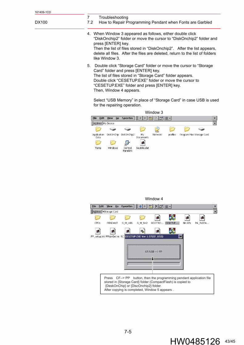
4. When Window 3 appeared as follows, either double click “DiskOnchip2” folder or move the cursor to “DiskOnchip2” folder and press [ENTER] key. Then the list of files stored in “DiskOnchip2”. After the list appears, delete all files. After the files are deleted, return to the list of folders like Window 3.
5. Double click “Storage Card” folder or move the cursor to “Storage Card” folder and press [ENTER] key. The list of files stored in “Storage Card” folder appears. Double click “CESETUP.EXE” folder or move the cursor to “CESETUP.EXE” folder and press [ENTER] key. Then, Window 4 appears.
Select “USB Memory” in place of “Storage Card” in case USB is used for the repairing operation.
Window 3
Window 4
Press �CF--> PP� button, then the programming pendant application filestored in {Storage Card} folder (CompactFlash) is copied to {DeskOnChip} or {DiscOnchip2} folder.After copying is completed, Window 5 appears .
7-5
HW0485126 43/45

7 TroubleshootingDX100 7.2 How to Repair Programming Pendant when Fonts are Garbled
161409-1CD
6. When Window 5 appeared, turn OFF the main power of the DX100. Insert the CompactFlash for upgrading the DX100, then turn ON the main power again by pressing [INTERLOCK] + [8] + [SELECT]. The window for upgrade appears, then, select {Software Upgrade} to execute upgrade.
Window 5
7. When upgrade operation is completed, turn OFF the main power of the DX100.
7-6
HW0485126 44/45
DX100UPGRADE PROCEDURE MANUAL
2HW0485126MANUAL NO.
Specifications are subject to change without noticefor ongoing product modifications and improvements.
45/45