fujitsu storage eternus dx100 s4/dx200 s4 ... storage eternus dx100 s4/dx200 s4, eternus dx100...
TRANSCRIPT

FUJITSU StorageETERNUS DX100 S4/DX200 S4,ETERNUS DX100 S3/DX200 S3Hybrid Storage Systems
Design Guide (Basic)
System configuration design
P3AM-7642-22ENZ0

Table of Contents
1. Function Overview 14
2. Basic Functions 16
RAID Functions.............................................................................................................................. 16Supported RAID.....................................................................................................................................................16
User Capacity (Logical Capacity)............................................................................................................................22
RAID Group............................................................................................................................................................24
Volume..................................................................................................................................................................26
Hot Spares.............................................................................................................................................................29
Data Protection............................................................................................................................. 31Data Block Guard ..................................................................................................................................................31
Disk Drive Patrol....................................................................................................................................................33
Redundant Copy....................................................................................................................................................34
Rebuild..................................................................................................................................................................35
Fast Recovery ........................................................................................................................................................36
Copyback/Copybackless .........................................................................................................................................37
Protection (Shield) ................................................................................................................................................39
Reverse Cabling.....................................................................................................................................................41
Operations Optimization (Virtualization/Automated Storage Tiering)........................................... 42Thin Provisioning ..................................................................................................................................................42
Flexible Tier ..........................................................................................................................................................48
Extreme Cache Pool ..............................................................................................................................................54
Optimization of Volume Configurations ........................................................................................ 55RAID Migration......................................................................................................................................................57
Logical Device Expansion ......................................................................................................................................59
LUN Concatenation ...............................................................................................................................................60
Wide Striping ........................................................................................................................................................63
Data Encryption ............................................................................................................................ 64Encryption with Self Encrypting Drive (SED)..........................................................................................................65
Firmware Data Encryption.....................................................................................................................................66
Key Management Server Linkage..........................................................................................................................67
User Access Management ............................................................................................................. 70Account Management ...........................................................................................................................................70
User Authentication ..............................................................................................................................................72
2FUJITSU Storage ETERNUS DX100 S4/DX200 S4, ETERNUS DX100 S3/DX200 S3 Hybrid Storage Systems Design Guide (Basic)
Copyright 2018 FUJITSU LIMITEDP3AM-7642-22ENZ0
Audit Log ..............................................................................................................................................................74
Environmental Burden Reduction ................................................................................................. 75Eco-mode..............................................................................................................................................................75
Power Consumption Visualization .........................................................................................................................78
Operation Management/Device Monitoring.................................................................................. 79Operation Management Interface.........................................................................................................................79
Performance Information Management................................................................................................................80
Event Notification .................................................................................................................................................82
Device Time Synchronization.................................................................................................................................85
Power Control ............................................................................................................................... 86Power Synchronized Unit.......................................................................................................................................86
Remote Power Operation (Wake On LAN) .............................................................................................................87
Backup (Advanced Copy) .............................................................................................................. 88Backup (SAN)........................................................................................................................................................89
Performance Tuning.................................................................................................................... 103Striping Size Expansion .......................................................................................................................................103
Assigned CMs ......................................................................................................................................................104
3. SAN Functions 105
Operations Optimization (Deduplication/Compression).............................................................. 105Deduplication/Compression ................................................................................................................................105
Improving Host Connectivity ....................................................................................................... 113Host Affinity ........................................................................................................................................................113
iSCSI Security .......................................................................................................................................................115
Stable Operation via Load Control............................................................................................... 115Quality of Service (QoS).......................................................................................................................................115
Host Response ....................................................................................................................................................117
Storage Cluster ....................................................................................................................................................118
Data Migration............................................................................................................................ 121Storage Migration ...............................................................................................................................................121
Non-disruptive Storage Migration............................................................................................... 123
Server Linkage Functions ............................................................................................................ 125Oracle VM Linkage ..............................................................................................................................................125
VMware Linkage..................................................................................................................................................126
Microsoft Linkage................................................................................................................................................131
Table of Contents
3FUJITSU Storage ETERNUS DX100 S4/DX200 S4, ETERNUS DX100 S3/DX200 S3 Hybrid Storage Systems Design Guide (Basic)
Copyright 2018 FUJITSU LIMITEDP3AM-7642-22ENZ0
OpenStack Linkage .............................................................................................................................................132
Logical Volume Manager (LVM) ..........................................................................................................................133
4. Connection Configuration 134
SAN Connection .......................................................................................................................... 134Host Interface .....................................................................................................................................................134
Access Method ....................................................................................................................................................137
Remote Connections ................................................................................................................... 140Remote Interfaces ...............................................................................................................................................141
Connectable Models............................................................................................................................................143
LAN Connection .......................................................................................................................... 144LAN for Operation Management (MNT Port) .......................................................................................................144
LAN for Remote Support (RMT Port) ....................................................................................................................146
LAN Control (Master CM/Slave CM)......................................................................................................................149
Network Communication Protocols .....................................................................................................................151
Power Supply Connection............................................................................................................ 153Input Power Supply Lines ....................................................................................................................................153
UPS Connection...................................................................................................................................................153
Power Synchronized Connections................................................................................................ 154Power Synchronized Connections (PWC) .............................................................................................................154
Power Synchronized Connections (Wake On LAN) ...............................................................................................157
5. Hardware Configurations 158
Configuration Schematics ........................................................................................................... 159
Optional Product Installation Conditions..................................................................................... 166Controller Module ...............................................................................................................................................166
Memory Extension ..............................................................................................................................................167
Host Interfaces ....................................................................................................................................................168
Unified License....................................................................................................................................................169
Drive Enclosures..................................................................................................................................................170
I/O Module ..........................................................................................................................................................170
Drives..................................................................................................................................................................171
Standard Installation Rules......................................................................................................... 174Controller Module ...............................................................................................................................................174
Host Interface .....................................................................................................................................................175
Drive Enclosure ...................................................................................................................................................177
Table of Contents
4FUJITSU Storage ETERNUS DX100 S4/DX200 S4, ETERNUS DX100 S3/DX200 S3 Hybrid Storage Systems Design Guide (Basic)
Copyright 2018 FUJITSU LIMITEDP3AM-7642-22ENZ0
I/O Module ..........................................................................................................................................................177
Drive ...................................................................................................................................................................178
Recommended RAID Group Configurations ................................................................................. 183
6. Maintenance/Expansion 186
Hot Swap/Hot Expansion ............................................................................................................ 186
User Expansion ........................................................................................................................... 189
SSD Sanitization.......................................................................................................................... 189
A. Function Specification List 190
List of Supported Protocols.......................................................................................................... 190
Target Pool for Each Function/Volume List .................................................................................. 190Target RAID Groups/Pools of Each Function.........................................................................................................191
Target Volumes of Each Function ........................................................................................................................192
Combinations of Functions That Are Available for Simultaneous Executions............................... 194Combinations of Functions That Are Available for Simultaneous Executions.......................................................194
Number of Processes That Can Be Executed Simultaneously ...............................................................................196
Capacity That Can Be Processed Simultaneously .................................................................................................196
Table of Contents
5FUJITSU Storage ETERNUS DX100 S4/DX200 S4, ETERNUS DX100 S3/DX200 S3 Hybrid Storage Systems Design Guide (Basic)
Copyright 2018 FUJITSU LIMITEDP3AM-7642-22ENZ0

List of Figures
Figure 1 RAID0 Concept..........................................................................................................................................17Figure 2 RAID1 Concept..........................................................................................................................................17Figure 3 RAID1+0 Concept......................................................................................................................................18Figure 4 RAID5 Concept..........................................................................................................................................18Figure 5 RAID5+0 Concept......................................................................................................................................19Figure 6 RAID6 Concept..........................................................................................................................................20Figure 7 RAID6-FR Concept.....................................................................................................................................21Figure 8 Example of a RAID Group .........................................................................................................................24Figure 9 Volume Concept .......................................................................................................................................26Figure 10 Hot Spares................................................................................................................................................29Figure 11 Data Block Guard......................................................................................................................................31Figure 12 Disk Drive Patrol.......................................................................................................................................33Figure 13 Redundant Copy Function ........................................................................................................................34Figure 14 Rebuild.....................................................................................................................................................35Figure 15 Fast Recovery ...........................................................................................................................................36Figure 16 Copyback..................................................................................................................................................37Figure 17 Copybackless ............................................................................................................................................38Figure 18 Protection (Shield) ...................................................................................................................................39Figure 19 Reverse Cabling........................................................................................................................................41Figure 20 Storage Capacity Virtualization.................................................................................................................43Figure 21 TPV Balancing (When Allocating Disproportionate TPV Physical Capacity Evenly) ....................................45Figure 22 TPV Balancing (When Distributing Host Accesses Evenly after TPP Expansion) ........................................46Figure 23 TPV/FTV Capacity Optimization .................................................................................................................47Figure 24 Flexible Tier..............................................................................................................................................49Figure 25 FTV Configuration.....................................................................................................................................50Figure 26 FTRP Balancing.........................................................................................................................................53Figure 27 Extreme Cache Pool..................................................................................................................................54Figure 28 RAID Migration (When Data Is Migrated to a High Capacity Drive)...........................................................57Figure 29 RAID Migration (When a Volume Is Moved to a Different RAID Level) ......................................................57Figure 30 RAID Migration.........................................................................................................................................58Figure 31 Logical Device Expansion (When Expanding the RAID Group Capacity)....................................................59Figure 32 Logical Device Expansion (When Changing the RAID Level).....................................................................59Figure 33 LUN Concatenation ..................................................................................................................................60Figure 34 LUN Concatenation (When the Concatenation Source Is a New Volume)..................................................61Figure 35 LUN Concatenation (When the Existing Volume Capacity Is Expanded) ...................................................61Figure 36 Wide Striping............................................................................................................................................63Figure 37 Data Encryption with Self Encrypting Drives (SED) ...................................................................................65Figure 38 Firmware Data Encryption ........................................................................................................................66Figure 39 Key Management Server Linkage.............................................................................................................68Figure 40 Account Management ..............................................................................................................................70Figure 41 Audit Log..................................................................................................................................................74Figure 42 Eco-mode.................................................................................................................................................75Figure 43 Power Consumption Visualization ............................................................................................................78Figure 44 Event Notification ....................................................................................................................................82Figure 45 Device Time Synchronization....................................................................................................................85Figure 46 Power Synchronized Unit..........................................................................................................................86Figure 47 Wake On LAN ...........................................................................................................................................87
6FUJITSU Storage ETERNUS DX100 S4/DX200 S4, ETERNUS DX100 S3/DX200 S3 Hybrid Storage Systems Design Guide (Basic)
Copyright 2018 FUJITSU LIMITEDP3AM-7642-22ENZ0

Figure 48 Example of Advanced Copy ......................................................................................................................88Figure 49 REC...........................................................................................................................................................91Figure 50 Restore OPC..............................................................................................................................................94Figure 51 EC or REC Reverse .....................................................................................................................................94Figure 52 Targets for the Multi-Copy Function .........................................................................................................95Figure 53 Multi-Copy................................................................................................................................................95Figure 54 Multi-Copy (Including SnapOPC+) ............................................................................................................96Figure 55 Multi-Copy (Using the Consistency Mode) ................................................................................................96Figure 56 Multi-Copy (Case 1: When Performing a Cascade Copy for an REC Session in Consistency Mode) .............97Figure 57 Multi-Copy (Case 2: When Performing a Cascade Copy for an REC Session in Consistency Mode) .............97Figure 58 Cascade Copy............................................................................................................................................98Figure 59 Cascade Copy (Using Three Copy Sessions).............................................................................................102Figure 60 Cascade Copy (Using Four Copy Sessions)...............................................................................................102Figure 61 Assigned CMs .........................................................................................................................................104Figure 62 Deduplication/Compression Overview ....................................................................................................106Figure 63 Deduplication Overview .........................................................................................................................106Figure 64 Compression Overview ...........................................................................................................................107Figure 65 Details of the Deduplication/Compression Function ...............................................................................111Figure 66 Host Affinity ...........................................................................................................................................113Figure 67 Associating Host Groups, CA Port Groups, and LUN Groups.....................................................................114Figure 68 QoS.........................................................................................................................................................115Figure 69 Copy Path Bandwidth Limit ....................................................................................................................116Figure 70 Host Response........................................................................................................................................117Figure 71 Storage Cluster .......................................................................................................................................118Figure 72 Mapping TFOVs, TFO Groups, and CA Port Pairs ......................................................................................119Figure 73 Storage Migration ..................................................................................................................................121Figure 74 Non-disruptive Storage Migration ..........................................................................................................123Figure 75 Oracle VM Linkage .................................................................................................................................125Figure 76 VMware Linkage.....................................................................................................................................126Figure 77 VVOL (Operational Configuration) ..........................................................................................................128Figure 78 VVOL (System Configuration) .................................................................................................................129Figure 79 Microsoft Linkage...................................................................................................................................131Figure 80 Logical Volume Manager (LVM) .............................................................................................................133Figure 81 Single Path Connection (When a SAN Connection Is Used — Direct Connection) .....................................137Figure 82 Single Path Connection (When a SAN Connection Is Used — Switch Connection) ....................................137Figure 83 Multipath Connection (When a SAN Connection Is Used — Basic Connection Configuration)...................138Figure 84 Multipath Connection (When a SAN Connection Is Used — Switch Connection).......................................138Figure 85 Multipath Connection (When a SAN Connection Is Used — for Enhanced Performance)..........................139Figure 86 Example of Non-Supported Connection Configuration (When Multiple Types of Remote Interfaces Are In-
stalled in the Same ETERNUS DX/AF)......................................................................................................140Figure 87 Example of Supported Connection Configuration (When Multiple Types of Remote Interfaces Are Installed
in the Same ETERNUS DX/AF) .................................................................................................................140Figure 88 An FC Connection for a Remote Copy between ETERNUS DX/AF Storage Systems (When Redundant Paths
Are Used) ...............................................................................................................................................141Figure 89 An FC Connection for a Remote Copy between ETERNUS DX/AF Storage Systems (When Lines Are Used).....
...............................................................................................................................................................141Figure 90 An iSCSI Connection for a Remote Copy between ETERNUS DX/AF Storage Systems (When Lines Are Used) .
...............................................................................................................................................................142Figure 91 Connection Example without a Dedicated Remote Support Port ............................................................145Figure 92 Connection Example When the IP Address of the Slave CM Is Set (and a Dedicated Remote Support Port Is
Not Used)...............................................................................................................................................145
List of Figures
7FUJITSU Storage ETERNUS DX100 S4/DX200 S4, ETERNUS DX100 S3/DX200 S3 Hybrid Storage Systems Design Guide (Basic)
Copyright 2018 FUJITSU LIMITEDP3AM-7642-22ENZ0

Figure 93 Overview of the AIS Connect Function ....................................................................................................146Figure 94 Security Features....................................................................................................................................147Figure 95 Connection Example with a Dedicated Remote Support Port..................................................................148Figure 96 Connection Example When the IP Address of the Slave CM Is Set (and a Dedicated Remote Support Port Is
Used) .....................................................................................................................................................149Figure 97 LAN Control (Switching of the Master CM)..............................................................................................150Figure 98 LAN Control (When the IP Address of the Slave CM Is Set)......................................................................150Figure 99 Power Supply Control Using a Power Synchronized Unit (When Connecting One or Two Servers) ...........154Figure 100 Power Supply Control Using a Power Synchronized Unit (When Connecting Three or More Servers).......156Figure 101 Power Supply Control Using Wake On LAN .............................................................................................157Figure 102 Minimum Configuration Diagram: ETERNUS DX100 S4/DX200 S4...........................................................159Figure 103 Minimum Configuration Diagram: ETERNUS DX100 S3/DX200 S3...........................................................160Figure 104 Maximum Configuration Diagram: ETERNUS DX100 S4/DX200 S4 ..........................................................161Figure 105 Maximum Configuration Diagram: ETERNUS DX100 S3/DX200 S3 ..........................................................163Figure 106 Enclosure Connection Path (When Only One Controller Is Installed).......................................................165Figure 107 Enclosure Connection Path (When Two Controllers Are Installed) ..........................................................165Figure 108 Controller Installation Order ...................................................................................................................174Figure 109 Installation Diagram for Host Interfaces (When Only One Controller Is Installed) ..................................175Figure 110 Host Interface Installation Diagram 1 (When Two Controllers Are Installed in the ETERNUS DX100 S4/
DX100 S3) ..............................................................................................................................................175Figure 111 Host Interface Installation Diagram 2 (When Two Controllers Are Installed in the ETERNUS DX100 S4/
DX100 S3) ..............................................................................................................................................176Figure 112 Host Interface Installation Diagram (When Two Controllers Are Installed in the ETERNUS DX200 S4/DX200
S3) .........................................................................................................................................................176Figure 113 I/O Module Installation Order .................................................................................................................177Figure 114 Drive Installation Diagram for High-Density Drive Enclosures ................................................................179Figure 115 Installation Diagram for 2.5" Drives .......................................................................................................181Figure 116 Installation Diagram for 3.5" Drives .......................................................................................................182Figure 117 Drive Combination 1 ..............................................................................................................................183Figure 118 Drive Combination 2 ..............................................................................................................................183Figure 119 Drive Combination 3 ..............................................................................................................................184Figure 120 Drive Combination 4 ..............................................................................................................................184Figure 121 Drive Combination 5 ..............................................................................................................................185
List of Figures
8FUJITSU Storage ETERNUS DX100 S4/DX200 S4, ETERNUS DX100 S3/DX200 S3 Hybrid Storage Systems Design Guide (Basic)
Copyright 2018 FUJITSU LIMITEDP3AM-7642-22ENZ0

List of Tables
Table 1 Basic Functions ........................................................................................................................................14Table 2 SAN Functions ..........................................................................................................................................15Table 3 RAID Level Comparison ............................................................................................................................21Table 4 Formula for Calculating User Capacity for Each RAID Level .......................................................................22Table 5 User Capacity per Drive.............................................................................................................................23Table 6 RAID Group Types and Usage....................................................................................................................24Table 7 Recommended Number of Drives per RAID Group ....................................................................................25Table 8 Number of Volumes That Can Be Created .................................................................................................26Table 9 Volumes That Can Be Created...................................................................................................................27Table 10 Hot Spare Installation Conditions.............................................................................................................29Table 11 Hot Spare Selection Criteria .....................................................................................................................30Table 12 TPP Maximum Number and Capacity........................................................................................................43Table 13 Chunk Size According to the Configured TPP Capacity...............................................................................43Table 14 Levels and Configurations for a RAID Group That Can Be Registered in a TPP...........................................44Table 15 TPP Thresholds .........................................................................................................................................44Table 16 TPV Thresholds .........................................................................................................................................45Table 17 Chunk Size and Data Transfer Unit ..........................................................................................................49Table 18 The Maximum Number and the Maximum Capacity of FTSPs ...................................................................50Table 19 Levels and Configurations for a RAID Group That Can Be Registered in a FTSP .........................................51Table 20 FTRP Thresholds .......................................................................................................................................52Table 21 FTV Thresholds .........................................................................................................................................52Table 22 Optimization of Volume Configurations....................................................................................................55Table 23 Functional Comparison between the SED Authentication Key (Common Key) and Key Management Server
Linkage ....................................................................................................................................................67Table 24 Available Functions for Default Roles .......................................................................................................71Table 25 Client Public Key (SSH Authentication).....................................................................................................72Table 26 Eco-mode Specifications...........................................................................................................................76Table 27 ETERNUS Web GUI Operating Environment ..............................................................................................79Table 28 Levels and Contents of Events That Are Notified ......................................................................................82Table 29 SNMP Specifications .................................................................................................................................83Table 30 Control Software (Advanced Copy) ...........................................................................................................88Table 31 List of Functions (Copy Methods) .............................................................................................................89Table 32 REC Data Transfer Mode ...........................................................................................................................91Table 33 Available Cascade Copy Combinations (When a Cascade Copy Performs Session 1 Followed by Session 2) ..
.................................................................................................................................................................99Table 34 Available Cascade Copy Combinations (When a Cascade Copy Performs Session 2 Followed by Session 1) ..
...............................................................................................................................................................100Table 35 Available Stripe Depth............................................................................................................................103Table 36 Deduplication/Compression Function Specifications...............................................................................107Table 37 Method for Enabling the Deduplication/Compression Function..............................................................108Table 38 Volumes That Are to Be Created depending on the Selection of "Deduplication" and "Compression"......109Table 39 Deduplication/Compression Setting for TPPs Where the Target Volumes Can Be Created .......................110Table 40 Target Deduplication/Compression Volumes of Each Function ...............................................................112Table 41 Storage Cluster Function Specifications ..................................................................................................119Table 42 Specifications for Paths and Volumes between the Local Storage System and the External Storage System
...............................................................................................................................................................123Table 43 Maximum VVOL Capacity........................................................................................................................129Table 44 VVOL Management Information Specifications ......................................................................................130
9FUJITSU Storage ETERNUS DX100 S4/DX200 S4, ETERNUS DX100 S3/DX200 S3 Hybrid Storage Systems Design Guide (Basic)
Copyright 2018 FUJITSU LIMITEDP3AM-7642-22ENZ0

Table 45 Ethernet Frame Capacity (Jumbo Frame Settings)..................................................................................135Table 46 Connectable Models and Available Remote Interfaces ...........................................................................143Table 47 LAN Port Availability...............................................................................................................................151Table 48 Number of Installable Drive Enclosures..................................................................................................170Table 49 Drive Characteristics ...............................................................................................................................173Table 50 Number of Installable Drives..................................................................................................................173Table 51 Hot Swap and Hot Expansion Availability for Components (ETERNUS DX100 S4/DX200 S4) ...................186Table 52 Hot Swap and Hot Expansion Availability for Components (ETERNUS DX100 S3/DX200 S3) ...................188Table 53 List of Supported Protocols.....................................................................................................................190Table 54 Combinations of Functions That Can Be Executed Simultaneously (1/2) ................................................194Table 55 Combinations of Functions That Can Be Executed Simultaneously (2/2) ................................................194
List of Tables
10FUJITSU Storage ETERNUS DX100 S4/DX200 S4, ETERNUS DX100 S3/DX200 S3 Hybrid Storage Systems Design Guide (Basic)
Copyright 2018 FUJITSU LIMITEDP3AM-7642-22ENZ0

Preface
Fujitsu would like to thank you for purchasing the FUJITSU Storage ETERNUS DX100 S4/DX200 S4, ETERNUSDX100 S3/DX200 S3 (hereinafter collectively referred to as ETERNUS DX).
The ETERNUS DX is designed to be connected to Fujitsu servers (Fujitsu SPARC Servers, PRIMEQUEST, PRIMERGY,and other servers) or non-Fujitsu servers.
This manual provides the system design information for the ETERNUS DX storage systems.
This manual is intended for use of the ETERNUS DX in regions other than Japan.
This manual applies to the latest controller firmware version.
Twenty-Second Edition
April 2018
11FUJITSU Storage ETERNUS DX100 S4/DX200 S4, ETERNUS DX100 S3/DX200 S3 Hybrid Storage Systems Design Guide (Basic)
Copyright 2018 FUJITSU LIMITEDP3AM-7642-22ENZ0

Trademarks
Third-party trademark information related to this product is available at:
http://www.fujitsu.com/global/products/computing/storage/eternus/trademarks.html
About This Manual
Intended AudienceThis manual is intended for field engineers or system administrators who design ETERNUS DX systems or use theETERNUS DX.
Related Information and DocumentsThe latest version of this manual and the latest information for your model are available at:
http://www.fujitsu.com/global/support/products/computing/storage/disk/manuals/
Refer to the following manuals of your model as necessary:
"Overview"
"ETERNUS Web GUI User's Guide"
"Configuration Guide -Server Connection-"
"ETERNUS CLI User's Guide"
"Site Planning Guide"
"Product List"
Document Conventions
■ Third-Party Product Names
• Oracle Solaris may be referred to as "Solaris", "Solaris Operating System", or "Solaris OS".
• Microsoft® Windows Server® may be referred to as "Windows Server".
■ Notice Symbols
The following notice symbols are used in this manual:
Indicates information that you need to observe when using the ETERNUS storage system.Make sure to read the information.
Indicates information and suggestions that supplement the descriptions included in thismanual.
Preface
12FUJITSU Storage ETERNUS DX100 S4/DX200 S4, ETERNUS DX100 S3/DX200 S3 Hybrid Storage Systems Design Guide (Basic)
Copyright 2018 FUJITSU LIMITEDP3AM-7642-22ENZ0

Warning SignsWarning signs are shown throughout this manual in order to prevent injury to the user and/or material damage.These signs are composed of a symbol and a message describing the recommended level of caution. The follow-ing explains the symbol, its level of caution, and its meaning as used in this manual.
This symbol indicates the possibility of serious or fatal injury if the ETERNUS DX is not usedproperly.
This symbol indicates the possibility of minor or moderate personal injury, as well as dam-age to the ETERNUS DX and/or to other users and their property, if the ETERNUS DX is notused properly.
This symbol indicates IMPORTANT information for the user to note when using the ETERNUSDX.
The following symbols are used to indicate the type of warnings or cautions being described.
Electric Shock The triangle emphasizes the urgency of the WARNING and CAUTION contents. Inside thetriangle and above it are details concerning the symbol (e.g. Electrical Shock).
No DisassemblyThe barred "Do Not..." circle warns against certain actions. The action which must be
avoided is both illustrated inside the barred circle and written above it (e.g. No Disassem-bly).
UnplugThe black "Must Do..." circle indicates actions that must be taken. The required action is
both illustrated inside the black disk and written above it (e.g. Unplug).
How Warnings are Presented in This ManualA message is written beside the symbol indicating the caution level. This message is marked with a vertical rib-bon in the left margin, to distinguish this warning from ordinary descriptions.
A display example is shown here.
Warning level indicator
Warning type indicator
Warning details
• To avoid damaging the ETERNUS storage system, pay attention to the following points when cleaning the ETERNUS storage system:
Warning layout ribbon
Example warning
- Make sure to disconnect the power when cleaning.- Be careful that no liquid seeps into the ETERNUS storage system when using cleaners, etc.- Do not use alcohol or other solvents to clean the ETERNUS storage system.
CAUTIONDo
Preface
13FUJITSU Storage ETERNUS DX100 S4/DX200 S4, ETERNUS DX100 S3/DX200 S3 Hybrid Storage Systems Design Guide (Basic)
Copyright 2018 FUJITSU LIMITEDP3AM-7642-22ENZ0

1. Function Overview
The ETERNUS DX provides various functions to ensure data integrity, enhance security, reduce cost, and optimizethe overall performance of the system.
The ETERNUS DX integrates block data (SAN area) and file data (NAS area) in a single device and also providesadvanced functions according to each connection.
These functions enable to respond to problems from various situations.
The ETERNUS DX has functions such as the SAN function (supports block data access), the NAS function (supportsfile data access), and basic functions that can be used without needing to recognize the SAN or the NAS connec-tion.
For more details about the basic functions, refer to "2. Basic Functions" (page 16). For more details about thefunctions that are used for a SAN connection, refer to "3. SAN Functions" (page 105).
Table 1 Basic Functions
Overview Function
Data protectionFunctions that ensure data integrity to improve data reliability.It is possible to detect and fix drive failures early.
"Data Block Guard" (page 31)"Disk Drive Patrol" (page 33)"Redundant Copy" (page 34)"Rebuild" (page 35)"Fast Recovery" (page 36)"Copyback/Copybackless" (page 37)"Protection (Shield)" (page 39)"Reverse Cabling" (page 41)
Resource utilization (virtualization/Automated Storage Tier-ing)Functions that deliver effective resource utilization.
"Thin Provisioning" (page 42)"Flexible Tier" (page 48)"Extreme Cache Pool" (page 54)
• Data capacity expansionFunctions that expand or relocate a RAID group or a volumein order to flexibly meet any increases in the amount of data.
• Guarantee of performanceA function that creates a volume that is striped in multipleRAID groups in order to improve performance.
"RAID Migration" (page 57)"Logical Device Expansion" (page 59)"LUN Concatenation" (page 60)"Wide Striping" (page 63)
Security measures (data encryption)Functions that encrypt data in the drive media to prevent thedata from being fraudulently decoded.
"Encryption with Self Encrypting Drive (SED)" (page 65)"Firmware Data Encryption" (page 66)"Key Management Server Linkage" (page 67)
Security measures (user access management)Functions to prevent information leakage that are caused by amalicious access.
"Account Management" (page 70)"User Authentication" (page 72)"Audit Log" (page 74)
Environmental burden reductionFunctions that adjust the operating time and the environmentof the installation location in order to reduce power consump-tion.
"Eco-mode" (page 75)"Power Consumption Visualization" (page 78)
Operation management (device monitoring)Function that reduce load on the system administrator, andthat improve system stability and increase operating ratio ofthe system.
"Operation Management Interface" (page 79)"Performance Information Management" (page 80)"Event Notification" (page 82)"Device Time Synchronization" (page 85)
Power controlPower control functions that are used to link power-on andpower-off operations with servers and perform scheduled opera-tions.
"Power Synchronized Unit" (page 86)"Remote Power Operation (Wake On LAN)" (page 87)
14FUJITSU Storage ETERNUS DX100 S4/DX200 S4, ETERNUS DX100 S3/DX200 S3 Hybrid Storage Systems Design Guide (Basic)
Copyright 2018 FUJITSU LIMITEDP3AM-7642-22ENZ0

Overview Function
• High-speed backup• Continuous businessData can be duplicated at any point without affecting other op-erations.
"Backup (SAN)" (page 89)
Performance tuningA function that can perform tuning in order to improve perform-ance.
"Striping Size Expansion" (page 103)"Assigned CMs" (page 104)
Table 2 SAN Functions
Overview Function
Operations Optimization (Deduplication/Compression)A function that eliminates duplicated data and compresses thedata to reduce the amount of written data.
"Deduplication/Compression" (page 105)
Security measures (unauthorized access prevention)Functions that prevent unintentional storage access.
"Host Affinity" (page 113)"iSCSI Security" (page 115)
Stable operationFor stable operation of server connections, the appropriate re-sponse action and the processing priority can be specified foreach server.If an error occurs in the storage system during operations, theconnected storage system is switched automatically and opera-tions can continue.
"Quality of Service (QoS)" (page 115)"Host Response" (page 117)"Storage Cluster" (page 118)
Data relocationA function that migrates data between ETERNUS storage sys-tems.
"Storage Migration" (page 121)
Non-disruptive data relocationA function that migrates data between ETERNUS storage sys-tems without stopping the business server.
"Non-disruptive Storage Migration" (page 123)
Information linkage (function linkage with servers)Functions that cooperate with a server to improve performancein a virtualized environment. Beneficial effects such as central-ized management of the entire storage system and a reductionof the load on servers can be realized.
"Oracle VM Linkage" (page 125)"VMware Linkage" (page 126)"Microsoft Linkage" (page 131)"OpenStack Linkage" (page 132)"Logical Volume Manager (LVM)" (page 133)
1. Function Overview
15FUJITSU Storage ETERNUS DX100 S4/DX200 S4, ETERNUS DX100 S3/DX200 S3 Hybrid Storage Systems Design Guide (Basic)
Copyright 2018 FUJITSU LIMITEDP3AM-7642-22ENZ0
2. Basic Functions
This chapter describes the functions that control the storage system.
RAID FunctionsThis section explains the points to note before configuring a system using the ETERNUS DX.
Supported RAIDThe ETERNUS DX supports the following RAID levels.
• RAID0 (striping)
• RAID1 (mirroring)
• RAID1+0 (striping of pairs of drives for mirroring)
• RAID5 (striping with distributed parity)
• RAID5+0 (double striping with distributed parity)
• RAID6 (striping with double distributed parity)
• RAID6-FR (provides the high speed rebuild function, and striping with double distributed parity)
Remember that a RAID0 configuration is not redundant. This means that if a RAID0 drive fails, the data willnot be recoverable.
This section explains the concepts and purposes (RAID level selection criteria) of the supported RAID levels.
When Nearline SAS disks that have 6TB or more are used, the available RAID levels are RAID0, RAID1, RAID6,and RAID6-FR.
16FUJITSU Storage ETERNUS DX100 S4/DX200 S4, ETERNUS DX100 S3/DX200 S3 Hybrid Storage Systems Design Guide (Basic)
Copyright 2018 FUJITSU LIMITEDP3AM-7642-22ENZ0
■ RAID Level Concept
A description of each RAID level is shown below.
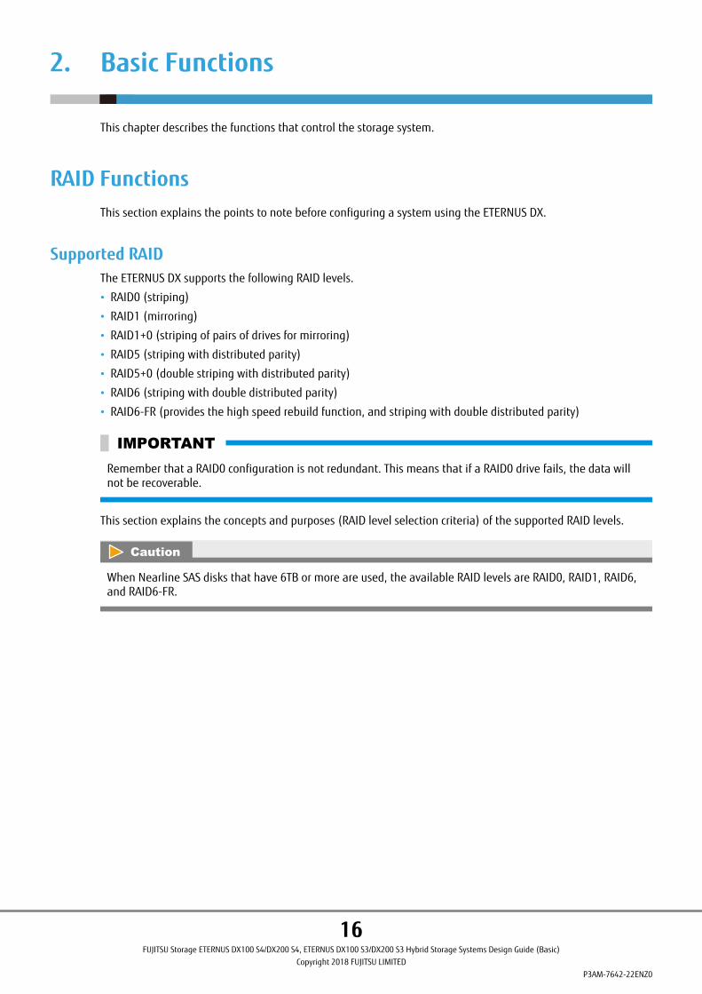
● RAID0 (Striping)
Data is split in unit of blocks and stored across multiple drives.
Figure 1 RAID0 Concept
A
C
B
D
Data writing request
Drive#0 Drive#1
A B C D
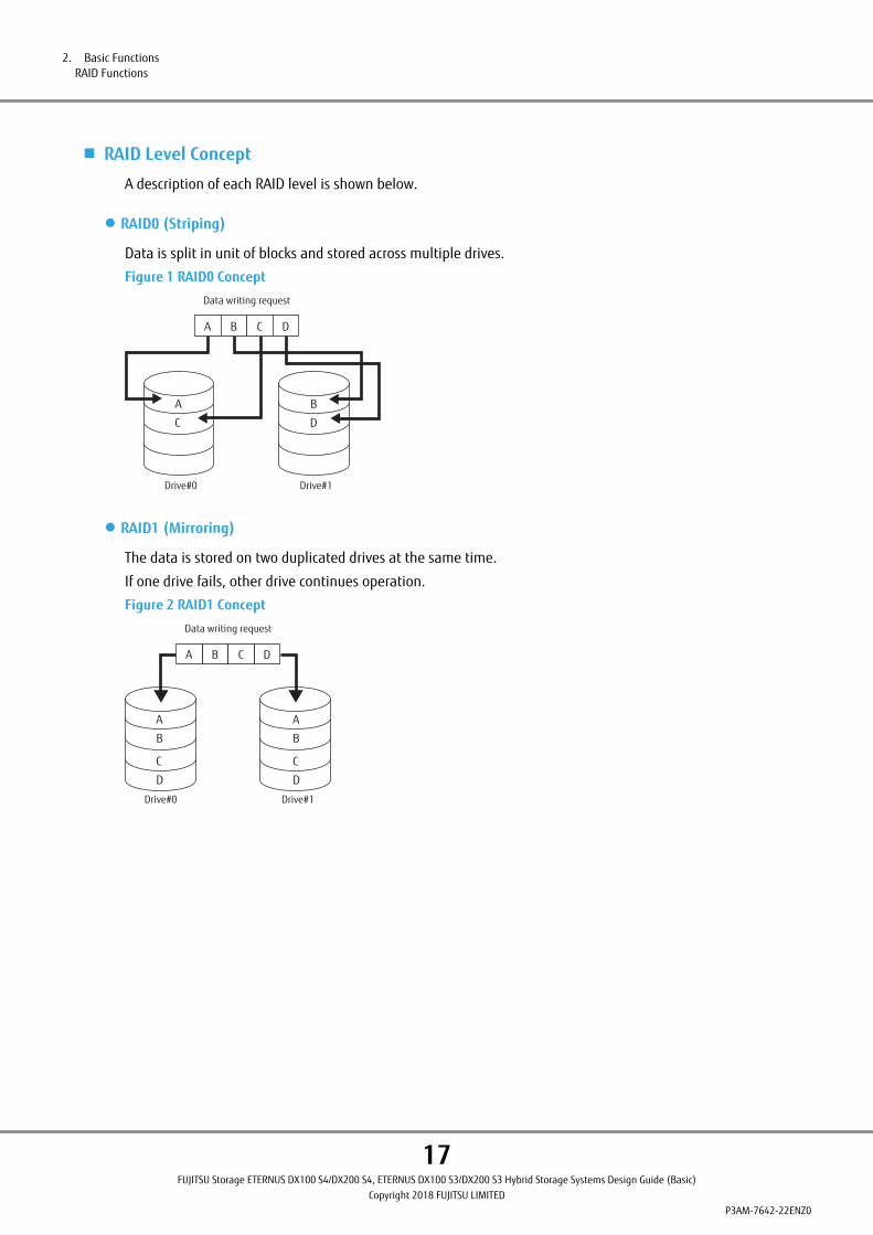
● RAID1 (Mirroring)
The data is stored on two duplicated drives at the same time.
If one drive fails, other drive continues operation.
Figure 2 RAID1 Concept
A
B
C
D
A B C D
Data writing request
A
B
C
D
Drive#0 Drive#1
2. Basic FunctionsRAID Functions
17FUJITSU Storage ETERNUS DX100 S4/DX200 S4, ETERNUS DX100 S3/DX200 S3 Hybrid Storage Systems Design Guide (Basic)
Copyright 2018 FUJITSU LIMITEDP3AM-7642-22ENZ0

● RAID1+0 (Striping of Pairs of Drives for Mirroring)
RAID1+0 combines the high I/O performance of RAID0 (striping) with the reliability of RAID1 (mirroring).
Figure 3 RAID1+0 Concept
Drive#3
Drive#7
D
D'
Drive#2
Drive#6
C
C'
Drive#1
Drive#5
B
B'
Drive#0
Drive#4
A
A'
Striping (RAID0)
Mirroring (RAID1)
Data writing request
A B C D
Mirroring
Mirroring
Mirroring
Mirroring
● RAID5 (Striping with Distributed Parity)
Data is divided into blocks and allocated across multiple drives together with parity information created fromthe data in order to ensure the redundancy of the data.
Figure 4 RAID5 Concept
A
E
I
M
A B C D
Data writing request
B
F
J
P M, N, O, P
C
G
P I, J, K, L
N
D
P E, F, G, H
K
O
H
L
P
Create parity data
P A, B, C, D
A B DC
Drive#0 Drive#1 Drive#2 Drive#3 Drive#4
Parity for data A to D: P A, B, C, DParity for data E to H: P E, F, G, HParity for data I to L: P I, J, K, LParity for data M to P: P M, N, O, P
2. Basic FunctionsRAID Functions
18FUJITSU Storage ETERNUS DX100 S4/DX200 S4, ETERNUS DX100 S3/DX200 S3 Hybrid Storage Systems Design Guide (Basic)
Copyright 2018 FUJITSU LIMITEDP3AM-7642-22ENZ0
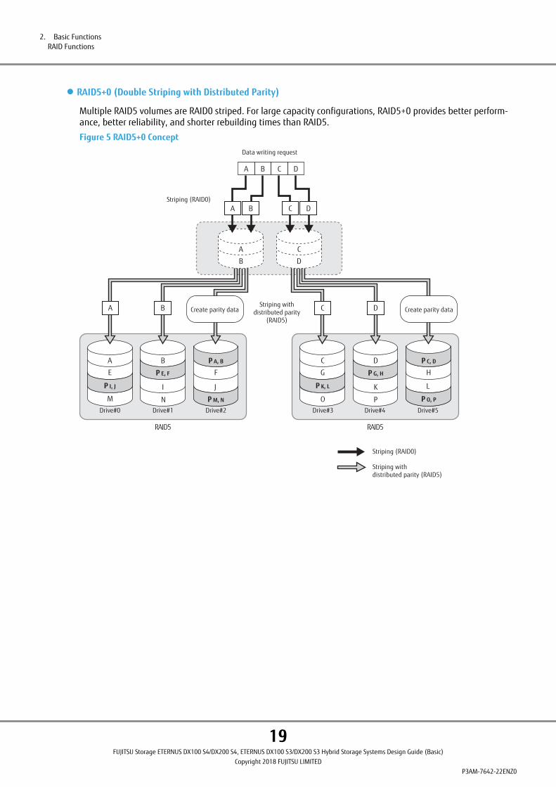
● RAID5+0 (Double Striping with Distributed Parity)
Multiple RAID5 volumes are RAID0 striped. For large capacity configurations, RAID5+0 provides better perform-ance, better reliability, and shorter rebuilding times than RAID5.
Figure 5 RAID5+0 Concept
Striping withdistributed parity (RAID5)
Striping (RAID0)
A
E
B
I
F
P A, B
P M, N
C
G H
P C, D
P O, P
Drive#0 Drive#1 Drive#2 Drive#3 Drive#4 Drive#5
D
KP K, L
Striping (RAID0)
Striping withdistributed parity
(RAID5)
J L
M N O P
P E, F
P I, J
P G, H
RAID5 RAID5
A B Create parity data D Create parity dataC
Data writing request
A
B
C
D
A B C D
A B C D
2. Basic FunctionsRAID Functions
19FUJITSU Storage ETERNUS DX100 S4/DX200 S4, ETERNUS DX100 S3/DX200 S3 Hybrid Storage Systems Design Guide (Basic)
Copyright 2018 FUJITSU LIMITEDP3AM-7642-22ENZ0

● RAID6 (Striping with Double Distributed Parity)
Allocating two different parities on different drives (double parity) makes it possible to recover from up to twodrive failures.
Figure 6 RAID6 Concept
P2 M, N, O, P
P2 I, J, K, L
A
E
I
M
A B C D
Data writing request
B
F
J
P1 M, N, O, P
C
G
P1 I, J, K, L
D
P1 E, F, G, H P2 E, F, G, H
N
K
O
P1 A, B, C, D
H
L
P
P2 A, B, C, D
A B DC Create parity data
Drive#0 Drive#1 Drive#2 Drive#3 Drive#4 Drive#5
Parity for data A to D: P1 A, B, C, D and P2 A, B, C, DParity for data E to H: P1 E, F, G, H and P2 E, F, G, HParity for data I to L: P1 I, J, K, L and P2 I, J, K, LParity for data M to P: P1 M, N, O, P and P2 M, N, O, P
2. Basic FunctionsRAID Functions
20FUJITSU Storage ETERNUS DX100 S4/DX200 S4, ETERNUS DX100 S3/DX200 S3 Hybrid Storage Systems Design Guide (Basic)
Copyright 2018 FUJITSU LIMITEDP3AM-7642-22ENZ0

● RAID6-FR (Provides the High Speed Rebuild Function, and Striping with Double Distributed Parity)
Distributing multiple data groups and reserved space equivalent to hot spares to the configuration drives makesit possible to recover from up to two drive failures. RAID6-FR requires less build time than RAID6.
Figure 7 RAID6-FR Concept
RAID6-FR ((3D+2P) × 2 + 1HS)
H
FHS
V
E
I
S
C
J
A
K
FHS
X W
F
FHS
N
T
G
Q
U
D
O
FHS
B
R
FHS
P
FHS
M
L
A B C D
Data writing request
A B C D
Create parity data Create parity data
P1 A, B, C
P1 P, Q, RP2 P, Q, R
P1 V, W, X
P1 M, N, O P2 M, N, O
P1 D, E, F
P2 J, K, L
P2 D, E, F
P1 J, K, L
P1 S, T, U
P2 G, H, I P1 G, H, I
P2 S, T, U
P2 A, B, C
P2 V, W, X
Drive#0 Drive#1 Drive#2 Drive#3 Drive#4 Drive#5 Drive#6 Drive#7 Drive#8 Drive#9 Drive#10
Parity for data A, B, C: P1 A, B, C and P2 A, B, CParity for data D, E, F: P1 D, E, F and P2 D, E, FParity for data G, H, I: P1 G, H, I and P2 G, H, IParity for data J, K, L: P1 J, K, L and P2 J, K, LParity for data M, N, O: P1 M, N, O and P2 M, N, OParity for data P, Q, R: P1 P, Q, R and P2 P, Q, RParity for data S, T, U: P1 S, T, U and P2 S, T, UParity for data V, W, X: P1 V, W, X and P2 V, W, X :Fast recovery Hot Spare: FHS
■ Reliability, Performance, Capacity for Each RAID Level
Table 3 shows the comparison result of reliability, performance, capacity for each RAID level.
Table 3 RAID Level Comparison
RAID level Reliability Performance (*1) Capacity
RAID0 ´ ◎ ◎
RAID1 ¡ ¡ △
RAID1+0 ¡ ◎ △
RAID5 ¡ ¡ ¡
RAID5+0 ¡ ¡ ¡
RAID6 ◎ ¡ ¡
RAID6-FR ◎ ¡ ¡
◎: Very good ¡: Good △: Reasonable ´: Poor
*1: Performance may differ according to the number of drives and the processing method from the host.
2. Basic FunctionsRAID Functions
21FUJITSU Storage ETERNUS DX100 S4/DX200 S4, ETERNUS DX100 S3/DX200 S3 Hybrid Storage Systems Design Guide (Basic)
Copyright 2018 FUJITSU LIMITEDP3AM-7642-22ENZ0

■ Recommended RAID Level
Select the appropriate RAID level according to the usage.
• Recommended RAID levels are RAID1, RAID1+0, RAID5, RAID5+0, RAID6, and RAID6-FR.
• When importance is placed upon read and write performance, a RAID1+0 configuration is recommended.
• For read only file servers and backup servers, RAID5, RAID5+0, RAID6, or RAID6-FR can also be used for higherefficiency. However, if the drive fails, note that data restoration from parities and rebuilding process may re-sult in a loss in performance.
• Using a RAID1+0, RAID5, RAID5+0, RAID6, or RAID6-FR configuration is recommended when SSDs are used.
• Using a RAID6 or RAID6-FR configuration is recommended when Nearline SAS disks that have 6TB or more areused. For details on the RAID levels that can be configured with Nearline SAS disks that have 6TB or more,refer to "Supported RAID" (page 16).
User Capacity (Logical Capacity)
User Capacity for Each RAID LevelThe user capacity depends on the capacity of drives that configure a RAID group and the RAID level.
Table 4 shows the formula for calculating the user capacity for each RAID level.
Table 4 Formula for Calculating User Capacity for Each RAID Level
RAID level Formula for user capacity computation
RAID0 Drive capacity ´ Number of drives
RAID1 Drive capacity ´ Number of drives ¸ 2
RAID1+0 Drive capacity ´ Number of drives ¸ 2
RAID5 Drive capacity ´ (Number of drives - 1)
RAID5+0 Drive capacity ´ (Number of drives - 2)
RAID6 Drive capacity ´ (Number of drives - 2)
RAID6-FR Drive capacity ´ (Number of drives - (2 ´ N) - Number of hot spares) (*1)
*1: "N" is the number of RAID6 configuration sets. For example, if a RAID6 group is configured with "(3D+2P)´2+1HS", N is "2".
2. Basic FunctionsRAID Functions
22FUJITSU Storage ETERNUS DX100 S4/DX200 S4, ETERNUS DX100 S3/DX200 S3 Hybrid Storage Systems Design Guide (Basic)
Copyright 2018 FUJITSU LIMITEDP3AM-7642-22ENZ0

User Capacity of DrivesTable 5 shows the user capacity for each drive.
The supported drives vary between the ETERNUS DX100 S4/DX200 S4 and the ETERNUS DX100 S3/DX200 S3. Fordetails about drives, refer to "Overview" of the currently used storage systems.
Table 5 User Capacity per Drive
Product name (*1) User capacity
400GB SSD 374,528MB
800GB SSD 750,080MB
960GB SSD 914,432MB
1.6TB SSD 1,501,440MB
1.92TB SSD 1,830,144MB
3.84TB SSD 3,661,568MB
7.68TB SSD 7,324,416MB
15.36TB SSD 14,650,112MB
300GB SAS disk 279,040MB
600GB SAS disk 559,104MB
900GB SAS disk 839,168MB
1.2TB SAS disk 1,119,232MB
1.8TB SAS disk 1,679,360MB
2.4TB SAS disk 2,239,744MB
1TB Nearline SAS disk 937,728MB
2TB Nearline SAS disk 1,866,240MB
3TB Nearline SAS disk 2,799,872MB
4TB Nearline SAS disk 3,733,504MB
6TB Nearline SAS disk (*2) 5,601,024MB
8TB Nearline SAS disk (*2) 7,468,288MB
10TB Nearline SAS disk (*2) 9,341,696MB
12TB Nearline SAS disk (*2) 11,210,496MB
*1: The capacity of the product names for the drives is based on the assumption that 1MB = 1,0002 bytes,while the user capacity for each drive is based on the assumption that 1MB = 1,0242 bytes. Furthermore,OS file management overhead will reduce the actual usable capacity.
The user capacity is constant regardless of the drive size (2.5"/3.5"), the SSD type (Value SSD and MLC SSD),or the encryption support (SED).
*2: For details on the RAID levels that can be configured with Nearline SAS disks that have 6TB or more, referto "Supported RAID" (page 16).
2. Basic FunctionsRAID Functions
23FUJITSU Storage ETERNUS DX100 S4/DX200 S4, ETERNUS DX100 S3/DX200 S3 Hybrid Storage Systems Design Guide (Basic)
Copyright 2018 FUJITSU LIMITEDP3AM-7642-22ENZ0

RAID GroupThis section explains RAID groups.
A RAID group is a group of drives. It is a unit that configures RAID. Multiple RAID groups with the same RAIDlevel or multiple RAID groups with different RAID levels can be set together in the ETERNUS DX. After a RAIDgroup is created, RAID levels can be changed and drives can be added.
Table 6 RAID Group Types and Usage
Type UsageMaximum capacity
Per RAID group Per storage sys-tem
RAID group Areas to store normal data. Volumes (Standard, WSV, SDV,SDPV) for work and Advanced Copy can be created in a RAIDgroup.
Approximately363TB (*1)
Depends on thenumber of instal-lable drives
REC Disk Buffer Areas that are dedicated for the REC Consistency mode totemporarily back up copy data.
Approximately55TB (*2)
110TB (*6)
Thin Provisioning Pool(TPP) (*3)
RAID groups that are used for Thin Provisioning in which theareas are managed as a Thin Provisioning Pool (TPP). ThinProvisioning Volumes (TPVs) can be created in a TPP.
2,048TB (*5)
Flexible Tier Sub Pool(FTSP) (*4)
RAID groups that are used for the Flexible Tier function inwhich the areas are managed as a Flexible Tier Sub Pool(FTSP). Larger pools (Flexible Tier Pools: FTRPs) are comprisedby layers of FTSPs. Flexible Tier Volumes (FTVs) can be createdin an FTSP.
*1: These values are for a 15.36TB SSD RAID6-FR ((13D+2P)´2+1HS) configuration.
For details on the number of configuration drives for each RAID level and recommended configurations,refer to Table 7.
*2: These values are for a 15.36TB SSD RAID1+0 (4D+4M) configuration.
*3: For details on the number of configuration drives for each RAID level and recommended configurations,refer to Table 14.
*4: For details on the number of configuration drives for each RAID level and recommended configurations,refer to Table 19.
*5: Total of the Thin Provisioning Pool capacity and the FTSP capacity.
*6: The maximum capacity of a storage system with one controller is 55TB.
The same size drives (2.5", 3.5") and the same kind of drives (SAS disks, Nearline SAS disks, SSDs, or SEDs) mustbe used to configure a RAID group.
Figure 8 Example of a RAID Group
RAID group 1 RAID group 2
SAS600GB
SAS600GB
SAS600GB
SAS600GB
SAS600GB
SSD400GB
SSD400GB
SSD400GB
SSD400GB
2. Basic FunctionsRAID Functions
24FUJITSU Storage ETERNUS DX100 S4/DX200 S4, ETERNUS DX100 S3/DX200 S3 Hybrid Storage Systems Design Guide (Basic)
Copyright 2018 FUJITSU LIMITEDP3AM-7642-22ENZ0
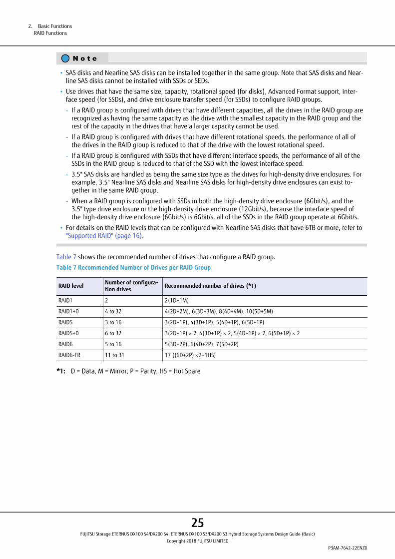
• SAS disks and Nearline SAS disks can be installed together in the same group. Note that SAS disks and Near-line SAS disks cannot be installed with SSDs or SEDs.
• Use drives that have the same size, capacity, rotational speed (for disks), Advanced Format support, inter-face speed (for SSDs), and drive enclosure transfer speed (for SSDs) to configure RAID groups.
- If a RAID group is configured with drives that have different capacities, all the drives in the RAID group arerecognized as having the same capacity as the drive with the smallest capacity in the RAID group and therest of the capacity in the drives that have a larger capacity cannot be used.
- If a RAID group is configured with drives that have different rotational speeds, the performance of all ofthe drives in the RAID group is reduced to that of the drive with the lowest rotational speed.
- If a RAID group is configured with SSDs that have different interface speeds, the performance of all of theSSDs in the RAID group is reduced to that of the SSD with the lowest interface speed.
- 3.5" SAS disks are handled as being the same size type as the drives for high-density drive enclosures. Forexample, 3.5" Nearline SAS disks and Nearline SAS disks for high-density drive enclosures can exist to-gether in the same RAID group.
- When a RAID group is configured with SSDs in both the high-density drive enclosure (6Gbit/s), and the3.5" type drive enclosure or the high-density drive enclosure (12Gbit/s), because the interface speed ofthe high-density drive enclosure (6Gbit/s) is 6Gbit/s, all of the SSDs in the RAID group operate at 6Gbit/s.
• For details on the RAID levels that can be configured with Nearline SAS disks that have 6TB or more, refer to"Supported RAID" (page 16).
Table 7 shows the recommended number of drives that configure a RAID group.
Table 7 Recommended Number of Drives per RAID Group
RAID level Number of configura-tion drives Recommended number of drives (*1)
RAID1 2 2(1D+1M)
RAID1+0 4 to 32 4(2D+2M), 6(3D+3M), 8(4D+4M), 10(5D+5M)
RAID5 3 to 16 3(2D+1P), 4(3D+1P), 5(4D+1P), 6(5D+1P)
RAID5+0 6 to 32 3(2D+1P) ´ 2, 4(3D+1P) ´ 2, 5(4D+1P) ´ 2, 6(5D+1P) ´ 2
RAID6 5 to 16 5(3D+2P), 6(4D+2P), 7(5D+2P)
RAID6-FR 11 to 31 17 ((6D+2P) ´2+1HS)
*1: D = Data, M = Mirror, P = Parity, HS = Hot Spare
2. Basic FunctionsRAID Functions
25FUJITSU Storage ETERNUS DX100 S4/DX200 S4, ETERNUS DX100 S3/DX200 S3 Hybrid Storage Systems Design Guide (Basic)
Copyright 2018 FUJITSU LIMITEDP3AM-7642-22ENZ0

• Sequential access performance hardly varies with the number of drives for the RAID group.
• Random access performance tends to be proportional to the number of drives for the RAID group.
• Use of higher capacity drives will increase the time required for the drive rebuild process to complete.
• For RAID5, RAID5+0, and RAID6, ensure that a single RAID group is not being configured with too manydrives.
If the number of drives increases, the time to perform data restoration from parities and Rebuild/Copybackwhen a drive fails also increases.
For details on the recommended number of drives, refer to Table 7.
• The RAID level that can be registered in REC Disk Buffers is RAID1+0. The drive configurations that can beregistered in REC Disk Buffers is 2D+2M or 4D+4M.
For details on the Thin Provisioning function and the RAID configurations that can be registered in Thin Pro-visioning Pools, refer to "Storage Capacity Virtualization" (page 42).
For details on the Flexible Tier functions and the RAID configurations that can be registered in Flexible TierPools, refer to "Automated Storage Tiering" (page 49).
An assigned CM is allocated to each RAID group. For details, refer to "Assigned CMs" (page 104).
For the installation locations of the drives that configure the RAID group, refer to "Recommended RAID GroupConfigurations" (page 183).
VolumeThis section explains volumes.
Logical drive areas in RAID groups are called volumes.
A volume is the basic RAID unit that can be recognized by the server.
Figure 9 Volume Concept
RAID group 1 RAID group 2
Volume 1
Volume 2Volume 3
A volume may be up to 128TB. However, the maximum capacity of volume varies depending on the OS of theserver.
The number of volumes that can be created in the ETERNUS DX is shown below. Volumes can be created untilthe combined total for each volume type reaches the maximum number of volumes.
Table 8 Number of Volumes That Can Be Created
Model Number of volumes (max.)
ETERNUS DX100 S4/DX100 S3 2,048 (*1)4,096 (*2)
ETERNUS DX200 S4/DX200 S3 4,096 (*1)8,192 (*2)
2. Basic FunctionsRAID Functions
26FUJITSU Storage ETERNUS DX100 S4/DX200 S4, ETERNUS DX100 S3/DX200 S3 Hybrid Storage Systems Design Guide (Basic)
Copyright 2018 FUJITSU LIMITEDP3AM-7642-22ENZ0

*1: The values if the controller firmware version is earlier than V10L60 or if the "Expand Volume Mode" is disa-bled.
*2: The values if the controller firmware version is V10L60 or later and if the "Expand Volume Mode" is ena-bled.
A volume can be expanded or moved if required. Multiple volumes can be concatenated and treated as a singlevolume. For availability of expansion, displacement, and concatenation for each volume, refer to "Target Vol-umes of Each Function" (page 192).
The types of volumes that are listed in the table below can be created in the ETERNUS DX.
Table 9 Volumes That Can Be Created
Type Usage Maximum capacity
Standard (Open) A standard volume is used for normal usage, such as file sys-tems and databases. The server recognizes it as a single logi-cal unit."Standard" is displayed as the type for this volume in ETERNUSWeb GUI/ETERNUS CLI and "Open" is displayed in ETERNUS SFsoftware.
128TB (*1)
Snap Data Volume (SDV) This area is used as the copy destination for SnapOPC/SnapOPC+. There is a SDV for each copy destination.
24 [MB] + copy sourcevolume capacity ´ 0.1 [%](*2)
Snap Data Pool Volume (SDPV) This volume is used to configure the Snap Data Pool (SDP)area. The SDP capacity equals the total capacity of the SDPVs.A volume is supplied from a SDP when the amount of updatesexceeds the capacity of the copy destination SDV.
2TB
Thin Provisioning Volume (TPV) This virtual volume is created in a Thin Provisioning Pool area. 128TB
Flexible Tier Volume (FTV) This volume is a target volume for layering. Data is automati-cally redistributed in small block units according to the accessfrequency. An FTV belongs to a Flexible Tier Pool.
128TB
Virtual Volumes (VVOLs) A VVOL is a VMware vSphere dedicated capacity virtualizationvolume. Operations can be simplified by associating VVOLswith virtual disks.Its volume type is FTV.
128TB
Deduplication/Compression Volume This volume is a virtual volume that is recognized by the serv-er when the Deduplication/Compression function is used. Itcan be created by enabling the Deduplication/Compressionsetting for a volume that is to be created. The data is seen bythe server as being non-deduplicated and uncompressed.The volume type is TPV.
128TB
Wide Striping Volume (WSV) This volume is created by concatenating distributed areas infrom 2 to 64 RAID groups. Processing speed is fast becausedata access is distributed.
128TB
ODX Buffer volume An ODX Buffer volume is a dedicated volume that is requiredto use the Offloaded Data Transfer (ODX) function of WindowsServer 2012 or later. It is used to save the source data whendata is updated while a copy is being processed.It can be created one per ETERNUS DX.Its volume type is Standard, TPV, or FTV.
1TB
*1: When multiple volumes are concatenated using the LUN Concatenation function, the maximum capacity isalso 128TB.
*2: The capacity differs depending on the copy source volume capacity.
After a volume is created, formatting automatically starts. A server can access the volume while it is being for-matted. Wait for the format to complete if high performance access is required for the volume.
2. Basic FunctionsRAID Functions
27FUJITSU Storage ETERNUS DX100 S4/DX200 S4, ETERNUS DX100 S3/DX200 S3 Hybrid Storage Systems Design Guide (Basic)
Copyright 2018 FUJITSU LIMITEDP3AM-7642-22ENZ0

• In the ETERNUS DX, volumes have different stripe sizes that depend on the RAID level and the stripe depthparameter.
For details about the stripe sizes for each RAID level and the stripe depth parameter values, refer to "ETER-NUS Web GUI User's Guide".
Note that the available user capacity can be fully utilized if an exact multiple of the stripe size is set for thevolume size. If an exact multiple of the stripe size is not set for the volume size, the capacity is not fullyutilized and some areas remain unused.
• When a Thin Provisioning Pool (TPP) is created, a control volume is created for each RAID group that config-ures the relevant TPP. Therefore, the maximum number of volumes that can be created in the ETERNUS DXdecreases by the number of RAID groups that configure a TPP.
• When the Flexible Tier function is enabled, 32 work volumes are created. The maximum number of volumesthat can be created in the ETERNUS DX decreases by the number of work volumes that are created.
• When a Flexible Tier Sub Pool (FTSP) is created, a control volume is created for each RAID group that config-ures the relevant FTSP. Therefore, the maximum number of volumes that can be created in the ETERNUS DXdecreases by the number of RAID groups that configure an FTSP.
• When using the VVOL function, a single volume for the VVOL management information is created the mo-ment a VVOL is created. The maximum number of volumes that can be created in the ETERNUS DX decrea-ses by the number of volumes for the VVOL management information that are created.
2. Basic FunctionsRAID Functions
28FUJITSU Storage ETERNUS DX100 S4/DX200 S4, ETERNUS DX100 S3/DX200 S3 Hybrid Storage Systems Design Guide (Basic)
Copyright 2018 FUJITSU LIMITEDP3AM-7642-22ENZ0

Hot SparesHot spares are used as spare drives for when drives in a RAID group fail, or when drives are in error status.
Figure 10 Hot Spares
Hot spare
Failure
RAID group
When the RAID level is RAID6-FR, data in a failed drive can be restored to a reserved space in a RAID groupeven when a drive error occurs because a RAID6-FR RAID group retains a reserved space for a whole drive inthe RAID group. If the reserved area is in use and an error occurs in another drive (2nd) in the RAID group,then the hot spare is used as a spare.
■ Types of Hot Spares
The following two types of hot spare are available:
• Global Hot Spare
This is available for any RAID group. When multiple hot spares are installed, the most appropriate drive is au-tomatically selected and incorporated into a RAID group.
• Dedicated Hot Spare
This is only available to the specified RAID group (one RAID group).
The Dedicated Hot Spare cannot be registered in a RAID group that is registered in TPPs, FTRPs, or REC DiskBuffers.
Assign "Dedicated Hot Spares" to RAID groups that contain important data, in order to preferentially improvetheir access to hot spares.
■ Number of Installable Hot Spares
The number of required hot spares is determined by the total number of drives.
The following table shows the recommended number of hot spares for each drive type.
Table 10 Hot Spare Installation Conditions
ModelTotal number of drives
Up to 120 Up to 240 Up to 264
ETERNUS DX100 S4/DX100 S3 1 2 —
ETERNUS DX200 S4/DX200 S3 1 2 3
2. Basic FunctionsRAID Functions
29FUJITSU Storage ETERNUS DX100 S4/DX200 S4, ETERNUS DX100 S3/DX200 S3 Hybrid Storage Systems Design Guide (Basic)
Copyright 2018 FUJITSU LIMITEDP3AM-7642-22ENZ0

■ Types of Drives
If a combination of SAS disks, Nearline SAS disks, SSDs, and SEDs is installed in the ETERNUS DX, each differenttype of drive requires a corresponding hot spare.
2.5" and 3.5" drive types are available. The drive type for high-density drive enclosures is 3.5".
There are two types of rotational speeds for SAS disks; 10,000rpm and 15,000rpm. If a drive error occurs and ahot spare is configured in a RAID group with different rotational speed drives, the performance of all the drivesin the RAID group is determined by the drive with the slowest rotational speed. When using SAS disks with dif-ferent rotational speeds, prepare hot spares that correspond to the different rotational speed drives if required.Even if a RAID group is configured with SAS disks that have different interface speeds, performance is not affec-ted.
There are two types of interface speeds for SSDs; 6Gbit/s and 12Gbit/s. If a drive error occurs and a hot spare isconfigured in a RAID group with different interface speed SSDs, the performance of all the SSDs in the RAIDgroup is determined by the SSDs with the slowest interface speed. Preparing SSDs with the same interface speedas the hot spare is recommended.
The capacity of each hot spare must be equal to the largest capacity of the same-type drives.
■ Selection Criteria
When multiple Global Hot Spares are installed, the following criteria are used to select which hot spare will re-place a failed drive:
Table 11 Hot Spare Selection Criteria
Selection or-der Selection criteria
1 A hot spare with the same type, same capacity, and same rotational speed (for disks) or same interface speed(for SSDs) as the failed drive
2 A hot spare with the same type, and same rotational speed (for disks) or same interface speed (for SSDs) as thefailed drive but with a larger capacity (*1)
3 A hot spare with the same type and same capacity as the failed drive but with a different rotational speed (fordisks) or a different interface speed (for SSDs)
4 A hot spare with the same type as the failed drive but with a larger capacity and a different rotational speed (fordisks) or a different interface speed (for SSDs) (*1)
*1: When there are multiple hot spares with a larger capacity than the failed drive, the hot spare with thesmallest capacity among them is used first.
2. Basic FunctionsRAID Functions
30FUJITSU Storage ETERNUS DX100 S4/DX200 S4, ETERNUS DX100 S3/DX200 S3 Hybrid Storage Systems Design Guide (Basic)
Copyright 2018 FUJITSU LIMITEDP3AM-7642-22ENZ0
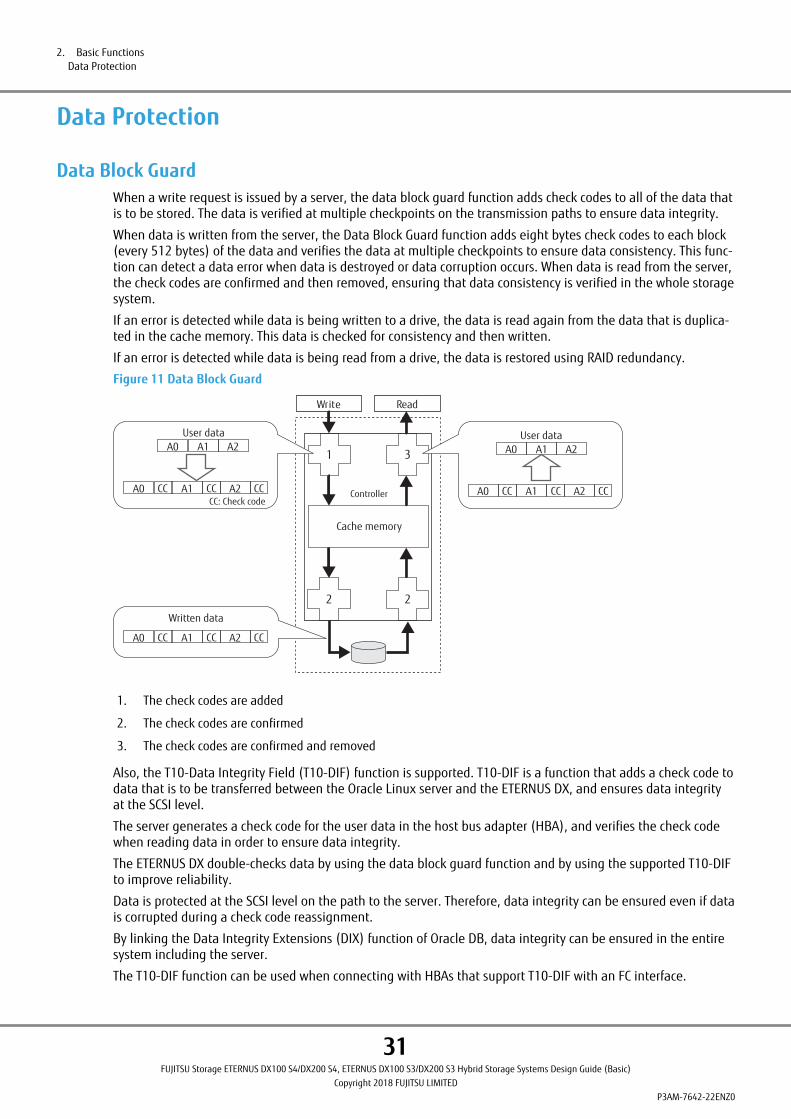
Data Protection
Data Block GuardWhen a write request is issued by a server, the data block guard function adds check codes to all of the data thatis to be stored. The data is verified at multiple checkpoints on the transmission paths to ensure data integrity.
When data is written from the server, the Data Block Guard function adds eight bytes check codes to each block(every 512 bytes) of the data and verifies the data at multiple checkpoints to ensure data consistency. This func-tion can detect a data error when data is destroyed or data corruption occurs. When data is read from the server,the check codes are confirmed and then removed, ensuring that data consistency is verified in the whole storagesystem.
If an error is detected while data is being written to a drive, the data is read again from the data that is duplica-ted in the cache memory. This data is checked for consistency and then written.
If an error is detected while data is being read from a drive, the data is restored using RAID redundancy.
Figure 11 Data Block Guard
Cache memory
2
1
2
3
Controller
Write
A0 A1 A2User data
A0 A1 A2User data
CC: Check codeA0 CC A1 CC A2 CC
Read
Written data
A0 CC A1 CC A2 CC
A0 CC A1 CC A2 CC
1. The check codes are added
2. The check codes are confirmed
3. The check codes are confirmed and removed
Also, the T10-Data Integrity Field (T10-DIF) function is supported. T10-DIF is a function that adds a check code todata that is to be transferred between the Oracle Linux server and the ETERNUS DX, and ensures data integrityat the SCSI level.
The server generates a check code for the user data in the host bus adapter (HBA), and verifies the check codewhen reading data in order to ensure data integrity.
The ETERNUS DX double-checks data by using the data block guard function and by using the supported T10-DIFto improve reliability.
Data is protected at the SCSI level on the path to the server. Therefore, data integrity can be ensured even if datais corrupted during a check code reassignment.
By linking the Data Integrity Extensions (DIX) function of Oracle DB, data integrity can be ensured in the entiresystem including the server.
The T10-DIF function can be used when connecting with HBAs that support T10-DIF with an FC interface.
2. Basic FunctionsData Protection
31FUJITSU Storage ETERNUS DX100 S4/DX200 S4, ETERNUS DX100 S3/DX200 S3 Hybrid Storage Systems Design Guide (Basic)
Copyright 2018 FUJITSU LIMITEDP3AM-7642-22ENZ0

The T10-DIF function can be enabled or disabled for each volume when the volumes are created. This functioncannot be enabled or disabled after a volume has been created.
• The T10-DIF function can be enabled only in the Standard volume.
• LUN concatenation cannot be performed for volumes where the T10-DIF function is enabled.
2. Basic FunctionsData Protection
32FUJITSU Storage ETERNUS DX100 S4/DX200 S4, ETERNUS DX100 S3/DX200 S3 Hybrid Storage Systems Design Guide (Basic)
Copyright 2018 FUJITSU LIMITEDP3AM-7642-22ENZ0

Disk Drive PatrolIn the ETERNUS DX, all of the drives are checked in order to detect drive errors early and to restore drives fromerrors or disconnect them.
The Disk Drive Patrol function regularly diagnoses and monitors the operational status of all drives that are in-stalled in the ETERNUS DX. Drives are checked (read check) regularly as a background process.
For drive checking, read check is performed sequentially for a part of the data in all the drives. If an error isdetected, data is restored using drives in the RAID group and the data is written back to another block of thedrive in which the error occurred.
Figure 12 Disk Drive Patrol
RAID group
D1
D1
D1
D2 D3 P
RAID group
Error
D1 to D3: Data
D1
P: Parity
Error detectionData is read andchecked.
The data is written backto another block.
Data reconstruction
Read checking is performed during the diagnosis.
These checks are performed in blocks (default 2MB) for each drive sequentially and are repeated until all theblocks for all the drives have been checked. Patrol checks are performed every second, 24 hours a day (default).
Drives that are stopped by Eco-mode are checked when the drives start running again.
The Maintenance Operation privilege is required to set detailed parameters.
2. Basic FunctionsData Protection
33FUJITSU Storage ETERNUS DX100 S4/DX200 S4, ETERNUS DX100 S3/DX200 S3 Hybrid Storage Systems Design Guide (Basic)
Copyright 2018 FUJITSU LIMITEDP3AM-7642-22ENZ0

Redundant CopyRedundant Copy is a function that copies the data of a drive that shows a possible sign of failure to a hot spare.
When the Disk Patrol function decides that preventative maintenance is required for a drive, the data of themaintenance target drive is re-created by the remaining drives and written to the hot spare. The RedundantCopy function enables data to be restored while maintaining data redundancy.
Figure 13 Redundant Copy Function
Hot spare
Creates data from the drives other thanthe maintenance target drive, andwrites data into the hot spare.
Disconnects the maintenance target driveand switches it to the hot spare.
Disconnected
RAID5 (Redundant)
Sign offailure
RAID5 (Redundant)
If a bad sector is detected when a drive is checked, an alternate track is automatically assigned. This drive isnot recognized as having a sign of drive failure during this process. However, the drive will be disconnectedby the Redundant Copy function if the spare sector is insufficient and the problem cannot be solved by assign-ing an alternate track.
• Redundant Copy speed
Giving priority to Redundant Copy over host access can be specified. By setting a higher Rebuild priority, theperformance of Redundant Copy operations may improve.
However, it should be noted that when the priority is high and a Redundant Copy operation is performedfor a RAID group, the performance (throughput) of this RAID group may be reduced.
2. Basic FunctionsData Protection
34FUJITSU Storage ETERNUS DX100 S4/DX200 S4, ETERNUS DX100 S3/DX200 S3 Hybrid Storage Systems Design Guide (Basic)
Copyright 2018 FUJITSU LIMITEDP3AM-7642-22ENZ0
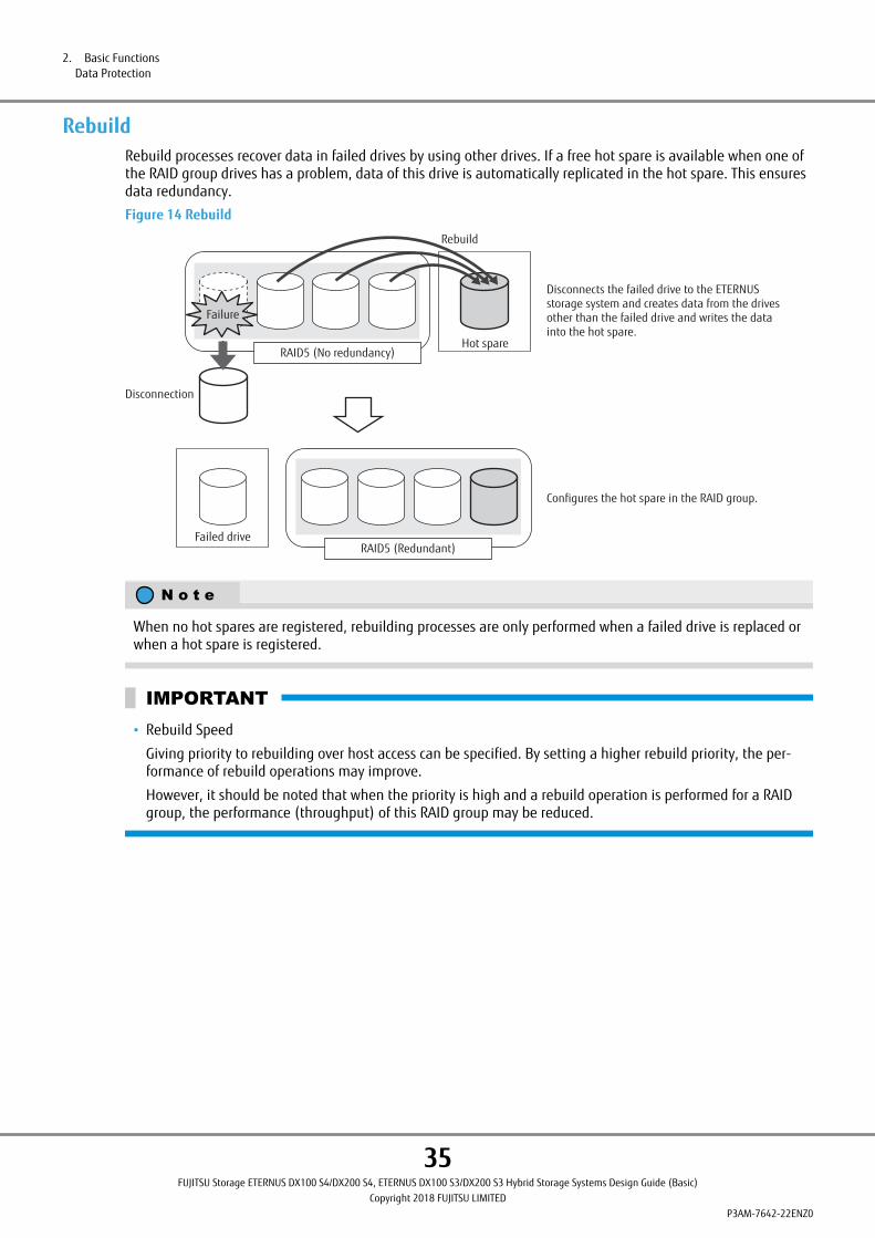
RebuildRebuild processes recover data in failed drives by using other drives. If a free hot spare is available when one ofthe RAID group drives has a problem, data of this drive is automatically replicated in the hot spare. This ensuresdata redundancy.
Figure 14 Rebuild
Disconnects the failed drive to the ETERNUSstorage system and creates data from the drivesother than the failed drive and writes the datainto the hot spare.
Rebuild
Hot spare
Failed drive
Configures the hot spare in the RAID group.
Failure
RAID5 (No redundancy)
RAID5 (Redundant)
Disconnection
When no hot spares are registered, rebuilding processes are only performed when a failed drive is replaced orwhen a hot spare is registered.
• Rebuild Speed
Giving priority to rebuilding over host access can be specified. By setting a higher rebuild priority, the per-formance of rebuild operations may improve.
However, it should be noted that when the priority is high and a rebuild operation is performed for a RAIDgroup, the performance (throughput) of this RAID group may be reduced.
2. Basic FunctionsData Protection
35FUJITSU Storage ETERNUS DX100 S4/DX200 S4, ETERNUS DX100 S3/DX200 S3 Hybrid Storage Systems Design Guide (Basic)
Copyright 2018 FUJITSU LIMITEDP3AM-7642-22ENZ0
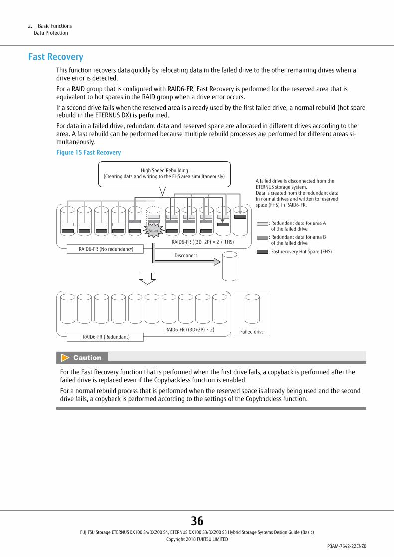
Fast RecoveryThis function recovers data quickly by relocating data in the failed drive to the other remaining drives when adrive error is detected.
For a RAID group that is configured with RAID6-FR, Fast Recovery is performed for the reserved area that isequivalent to hot spares in the RAID group when a drive error occurs.
If a second drive fails when the reserved area is already used by the first failed drive, a normal rebuild (hot sparerebuild in the ETERNUS DX) is performed.
For data in a failed drive, redundant data and reserved space are allocated in different drives according to thearea. A fast rebuild can be performed because multiple rebuild processes are performed for different areas si-multaneously.
Figure 15 Fast Recovery
Failed driveRAID6-FR ((3D+2P) × 2)
RAID6-FR (No redundancy)
: Redundant data for area A of the failed drive
: Redundant data for area B of the failed drive
: Fast recovery Hot Spare (FHS)
Failure
RAID6-FR ((3D+2P) × 2 + 1HS)
High Speed Rebuilding(Creating data and writing to the FHS area simultaneously)
Disconnect
RAID6-FR (Redundant)
A failed drive is disconnected from the ETERNUS storage system.Data is created from the redundant data in normal drives and written to reserved space (FHS) in RAID6-FR.
For the Fast Recovery function that is performed when the first drive fails, a copyback is performed after thefailed drive is replaced even if the Copybackless function is enabled.
For a normal rebuild process that is performed when the reserved space is already being used and the seconddrive fails, a copyback is performed according to the settings of the Copybackless function.
2. Basic FunctionsData Protection
36FUJITSU Storage ETERNUS DX100 S4/DX200 S4, ETERNUS DX100 S3/DX200 S3 Hybrid Storage Systems Design Guide (Basic)
Copyright 2018 FUJITSU LIMITEDP3AM-7642-22ENZ0

Copyback/CopybacklessA Copyback process copies data in a hot spare to the new drive that is used to replace the failed drive.
Figure 16 Copyback
RAID5 (Redundant)
After replacing has been completed,copies the data from the hot spareto the new drive.
Hot spareRAID5 (Redundant)
After rebuilding has been completed, replaces the failed drive with the new drive.
Failed driveRAID5 (Redundant)
Copyback
• Copyback speed
Giving priority to Copyback over host access can be specified. By setting a higher Rebuild priority, the per-formance of Copyback operations may improve.
However, it should be noted that when the priority is high and a Copyback operation is performed for aRAID group, the performance (throughput) of this RAID group may be reduced.
If copybackless is enabled, the drives that are registered in the hot spare become part of the RAID group config-uration drives after a rebuild or a redundant copy is completed for the hot spare.
The failed drive is disconnected from the RAID group configuration drives and then registered as a hot spare.Copyback is not performed for the data even if the failed drive is replaced by a new drive because the failed driveis used as a hot spare.
A copyback operation is performed when the following conditions for the copybackless target drive (or hotspare) and the failed drive are the same.
• Drive type (SAS disks, Nearline SAS disks, SSDs, and Self Encrypting Drives [SEDs])
• Size (2.5" and 3.5" [including high-density drive enclosures])
2. Basic FunctionsData Protection
37FUJITSU Storage ETERNUS DX100 S4/DX200 S4, ETERNUS DX100 S3/DX200 S3 Hybrid Storage Systems Design Guide (Basic)
Copyright 2018 FUJITSU LIMITEDP3AM-7642-22ENZ0
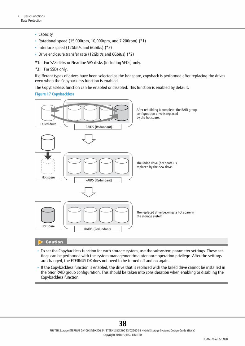
• Capacity
• Rotational speed (15,000rpm, 10,000rpm, and 7,200rpm) (*1)
• Interface speed (12Gbit/s and 6Gbit/s) (*2)
• Drive enclosure transfer rate (12Gbit/s and 6Gbit/s) (*2)
*1: For SAS disks or Nearline SAS disks (including SEDs) only.
*2: For SSDs only.
If different types of drives have been selected as the hot spare, copyback is performed after replacing the driveseven when the Copybackless function is enabled.
The Copybackless function can be enabled or disabled. This function is enabled by default.
Figure 17 Copybackless
The failed drive (hot spare) isreplaced by the new drive.
The replaced drive becomes a hot spare inthe storage system.
Hot spareRAID5 (Redundant)
Failed drive
Hot spare
After rebuilding is complete, the RAID groupconfiguration drive is replacedby the hot spare.
RAID5 (Redundant)
RAID5 (Redundant)
• To set the Copybackless function for each storage system, use the subsystem parameter settings. These set-tings can be performed with the system management/maintenance operation privilege. After the settingsare changed, the ETERNUS DX does not need to be turned off and on again.
• If the Copybackless function is enabled, the drive that is replaced with the failed drive cannot be installed inthe prior RAID group configuration. This should be taken into consideration when enabling or disabling theCopybackless function.
2. Basic FunctionsData Protection
38FUJITSU Storage ETERNUS DX100 S4/DX200 S4, ETERNUS DX100 S3/DX200 S3 Hybrid Storage Systems Design Guide (Basic)
Copyright 2018 FUJITSU LIMITEDP3AM-7642-22ENZ0

Protection (Shield)The Protection (Shield) function diagnoses temporary drive errors. A drive can continue to be used if it is deter-mined to be normal. The target drive temporarily changes to diagnosis status when drive errors are detected bythe Disk Drive Patrol function or error notifications.
For a drive that configures a RAID group, data is moved to a hot spare by a rebuild or redundant copy before thedrive is diagnosed. For a drive that is disconnected from a RAID group, whether the drive has a permanent erroror a temporary error is determined. The drive can be used again if it is determined that the drive has only atemporary error.
The target drives of the Protection (Shield) function are all the drives that are registered in RAID groups or regis-tered as hot spares. Note that the Protection (Shield) function is not available for unused drives.
The Protection (Shield) function can be enabled or disabled. This function is enabled by default.
Figure 18 Protection (Shield)
Redundant Copy
Hot spare
Hot spare
Temporary protection
DiagnosingRAID5 (Redundant)
RAID5 (Redundant)
RAID5 (Redundant)
The target drive for the Protection (Shield)function is disconnected temporarilyand diagnosed.
Data is created from the drivesthat are not the target drivesfor the Protection (Shield) function andwritten to the hot spare.
Suspend
If the drive is determined to benormal after the diagnosis isperformed, the drive is reconnectedto the storage system (*1).
RAID5 (Redundant)
Particularerror message
*1: If copybackless is enabled, the drive is used as a hot spare disk. If copybackless is disabled, the drive isused as a RAID group configuration drive and copyback starts. The copybackless setting can be enabled ordisabled until the drive is replaced.
2. Basic FunctionsData Protection
39FUJITSU Storage ETERNUS DX100 S4/DX200 S4, ETERNUS DX100 S3/DX200 S3 Hybrid Storage Systems Design Guide (Basic)
Copyright 2018 FUJITSU LIMITEDP3AM-7642-22ENZ0
• The target drives are deactivated and then reactivated during temporary drive protection. Even though asystem status error may be displayed during this period, this phenomenon is only temporary. The statusreturns to normal after the diagnosis is complete.
The following phenomenon may occur during temporary drive protection.
- The Fault LEDs (amber) on the operation panel and the drive turn on
- An error status is displayed by the ETERNUS Web GUI and the ETERNUS CLI
• Error or Warning is displayed as the system status
• Error, Warning, or Maintenance is displayed as the system status
• Target drives of the Protection (Shield) function only need to be replaced when drive reactivation fails.
If drive reactivation fails, a drive failure error is notified as an event notification message (such as SNMP/REMCS). When drive reactivation is successful, an error message is not notified. To notify this message, usethe event notification settings.
• To set the Protection (Shield) function for each storage system, use the subsystem parameter settings. Themaintenance operation privilege is required to perform this setting.
After the settings are changed, the ETERNUS DX does not need to be turned off and on again.
2. Basic FunctionsData Protection
40FUJITSU Storage ETERNUS DX100 S4/DX200 S4, ETERNUS DX100 S3/DX200 S3 Hybrid Storage Systems Design Guide (Basic)
Copyright 2018 FUJITSU LIMITEDP3AM-7642-22ENZ0
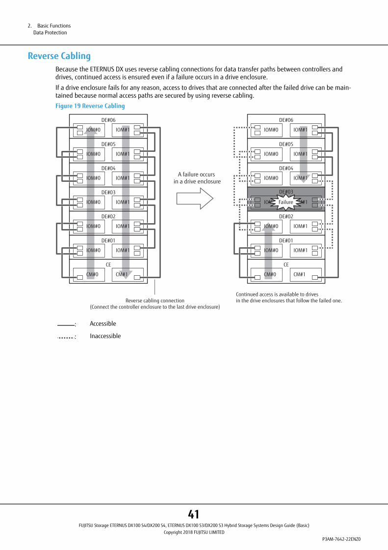
Reverse CablingBecause the ETERNUS DX uses reverse cabling connections for data transfer paths between controllers anddrives, continued access is ensured even if a failure occurs in a drive enclosure.
If a drive enclosure fails for any reason, access to drives that are connected after the failed drive can be main-tained because normal access paths are secured by using reverse cabling.
Figure 19 Reverse Cabling
CM#0 CM#1
CE
IOM#0 IOM#1
DE#01
IOM#0 IOM#1
DE#02
IOM#0 IOM#1
DE#03
IOM#0 IOM#1
DE#04
IOM#0 IOM#1
DE#05
IOM#0 IOM#1
DE#06
IOM#0 IOM#1
DE#06
CM#0 CM#1
CE
IOM#0 IOM#1
DE#01
IOM#0 IOM#1
DE#02
IOM#0 IOM#1
DE#03
IOM#0 IOM#1
DE#04
IOM#0 IOM#1
DE#05
Failure
Reverse cabling connection(Connect the controller enclosure to the last drive enclosure)
A failure occurs in a drive enclosure
Continued access is available to drivesin the drive enclosures that follow the failed one.
: Accessible
: Inaccessible
2. Basic FunctionsData Protection
41FUJITSU Storage ETERNUS DX100 S4/DX200 S4, ETERNUS DX100 S3/DX200 S3 Hybrid Storage Systems Design Guide (Basic)
Copyright 2018 FUJITSU LIMITEDP3AM-7642-22ENZ0

Operations Optimization (Virtualization/Automated StorageTiering)
A single controller configuration differs from a dual controller configuration in the following ways:
• The Thin Provisioning function cannot be used.
• The Flexible Tier function cannot be used.
Thin ProvisioningThe Thin Provisioning function has the following features:
• Storage Capacity Virtualization
The physical storage capacity can be reduced by allocating the virtual drives to a server, which allows efficientuse of the storage capacity. The volumes more than the capacity of all the installed drives can be allocated bysetting the capacity required for virtual volumes in the future.
• TPV Balancing
I/O access to the virtual volume can be distributed among the RAID groups in a pool, by relocating and balanc-ing the physical allocation status of the virtual volume.
• TPV/FTV Capacity Optimization (Zero Reclamation)
Data in physically allocated areas are checked in blocks and unnecessary areas (areas where 0 is allocated toall of the data in each block) are released to unallocated areas.
Storage Capacity VirtualizationThin Provisioning improves the usability of the drives by managing the physical drives in a pool, and sharing theunused capacity among the virtual volumes in the pool. The volume capacity that is seen from the server is vir-tualized to allow the server to recognize a larger capacity than the physical volume capacity. Because a largecapacity virtual volume can be defined, the drives can be used in a more efficient and flexible manner.
2. Basic FunctionsOperations Optimization (Virtualization/Automated Storage Tiering)
42FUJITSU Storage ETERNUS DX100 S4/DX200 S4, ETERNUS DX100 S3/DX200 S3 Hybrid Storage Systems Design Guide (Basic)
Copyright 2018 FUJITSU LIMITEDP3AM-7642-22ENZ0

Initial cost can be reduced because less drive capacity is required even if the capacity requirements cannot beestimated. The power consumption requirements can also be reduced because a fewer number of drives are in-stalled.
Figure 20 Storage Capacity Virtualization
Virtual volumeData that is actually used
MappingWrite
Allocated as required
AllocatedPhysical drives
RAID groupManagement server
In the Thin Provisioning function, the RAID group, which is configured with multiple drives, is managed as a ThinProvisioning Pool (TPP). When a Write request is issued, a physical area is allocated to the virtual volume. Thefree space in the TPP is shared among the virtual volumes which belong to the TPP, and a virtual volume, whichis larger than the drive capacity in the ETERNUS DX, can be created. A virtual volume to be created in a TPP isreferred to as a Thin Provisioning Volume (TPV).
• Thin Provisioning Pool (TPP)
A TPP is a physical drive pool which is configured with one or more RAID groups. TPP capacity can be expandedin the units of RAID groups.
The following table shows the maximum number and the maximum capacity of TPPs that can be registered inthe ETERNUS DX.
Table 12 TPP Maximum Number and Capacity
Item ETERNUS DX100 S4/DX100 S3 ETERNUS DX200 S4/DX200 S3
Number of pools (max.) 72 (*1) 132 (*1)
Pool capacity (max.) 2,048TB (*2)
*1: The maximum total number of Thin Provisioning Pools and FTSPs.
*2: The maximum pool capacity is the capacity that combines the FTSP capacity and the Thin ProvisioningPool capacity in the ETERNUS DX.
The following table shows the TPP chunk size that is applied when TPPs are created.
Table 13 Chunk Size According to the Configured TPP Capacity
Setting value of the maximum pool capacity Chunk size (*1)
Up to 256TB 21MB
Up to 512TB 42MB
Up to 1,024TB 84MB
Up to 2,048TB 168MB
2. Basic FunctionsOperations Optimization (Virtualization/Automated Storage Tiering)
43FUJITSU Storage ETERNUS DX100 S4/DX200 S4, ETERNUS DX100 S3/DX200 S3 Hybrid Storage Systems Design Guide (Basic)
Copyright 2018 FUJITSU LIMITEDP3AM-7642-22ENZ0

*1: Chunk size is for delimiting data. The chunk size is automatically set according to the maximum pool ca-pacity.
To perform encryption, specify encryption by firmware when creating a TPP, or select the Self Encrypting Drive(SED) for configuration when creating a TPP.
The following table shows the RAID configurations that can be registered in a TPP.
Table 14 Levels and Configurations for a RAID Group That Can Be Registered in a TPP
RAID level Number of configurable drives Recommended configura-tions
RAID0 4 (4D) —
RAID1 2 (1D+1M) 2 (1D+1M)
RAID1+0 4 (2D+2M), 8 (4D+4M), 16 (8D+8M), 24 (12D+12M) 8 (4D+4M)
RAID5 4 (3D+1P), 5 (4D+1P), 8 (7D+1P), 9 (8D+1), 13 (12D+1P) 4 (3D+1P), 8 (7D+1P)
RAID6 6 (4D+2P), 8 (6D+2P), 10 (8D+2P) 8 (6D+2P)
RAID6-FR 13 ((4D+2P) ´2+1HS), 17 ((6D+2P) ´2+1HS)31 ((8D+2P) ´3+1HS), 31 ((4D+2P) ´5+1HS)
17 ((6D+2P) ´2+1HS)
• Thin Provisioning Volume (TPV)
The maximum capacity of a TPV is 128TB. Note that the total TPV capacity must be smaller than the maximumcapacity of the TPP.
When creating a TPV, the Allocation method can be selected.
- Thin
When data is written from the host to a TPV, a physical area is allocated to the created virtual volume. Thecapacity size (chunk size) that is applied is the same value as the chunk size of the TPP where the TPV iscreated. The physical storage capacity can be reduced by allocating a virtualized storage capacity.
- Thick
When creating a volume, the physical area is allocated to the entire volume area. This can be used for vol-umes in the system area to prevent a system stoppage due to a pool capacity shortage during operations.
In general, selecting "Thin" is recommended. The Allocation method can be changed after a TPV is created.
Perform a TPV/FTV capacity optimization if "Thick" has changed to "Thin". By optimizing the capacity, the areathat was allocated to a TPV is released and the TPV becomes usable. If a TPV/FTV capacity optimization is notperformed, the usage of the TPV does not change even after the Allocation method is changed.
The capacity of a TPV can be expanded after it is created.
For details on the number of TPVs that can be created, refer to "Volume" (page 26).
● Threshold Monitoring of Used Capacity
When the used capacity of a TPP reaches the threshold, a notification is sent to the notification destination,(SNMP Trap, e-mail, or Syslog) specified using the [Setup Event Notification] function. There are two types ofthresholds: "Attention" and "Warning". A different value can be specified for each threshold type.
Also, ETERNUS SF Storage Cruiser can be used to monitor the used capacity.
• TPP Thresholds
There are two TPP usage thresholds: Attention and Warning.
Table 15 TPP Thresholds
Threshold Selectable range Default Setting conditions
Attention 5 (%) to 80 (%) 75 (%) Attention threshold £ Warning thresholdThe "Attention" threshold can be omitted.Warning 5 (%) to 99 (%) 90 (%)
2. Basic FunctionsOperations Optimization (Virtualization/Automated Storage Tiering)
44FUJITSU Storage ETERNUS DX100 S4/DX200 S4, ETERNUS DX100 S3/DX200 S3 Hybrid Storage Systems Design Guide (Basic)
Copyright 2018 FUJITSU LIMITEDP3AM-7642-22ENZ0

• TPV Thresholds
There is only one TPV usage threshold: Attention. When the physically allocated capacity of a TPV reaches thethreshold, a response is sent to a host via a sense. The threshold is determined by the ratio of free space in theTPP and the unallocated TPV capacity.
Table 16 TPV Thresholds
Threshold Selectable range Default
Attention 1 (%) to 100 (%) 80 (%)
• Use of TPVs is also not recommended when the OS writes meta information to the whole LUN during filesystem creation.
• TPVs should be backed up of files as sets of their component files. While backing up a whole TPV is notdifficult, unallocated areas will also be backed up as dummy data. If the TPV then needs to be restored fromthe backup, the dummy data is also "restored". This requires allocation of the physical drive area for theentire TPV capacity, which negates the effects of thin provisioning.
• For advanced performance tuning, use standard RAID groups.
• Refer to the applicable OS and file system documentation before dynamically expanding the volume ca-pacity because expanded volumes may not be recognized by some types and versions of server-side plat-forms (OSs).
• If a TPP includes one or more RAID groups that are configured with Advanced Format drives, all TPVs createdin the relevant TPP are treated as Advanced Format volumes. In this case, the write performance may bereduced when accessing the relevant TPV from an OS or an application that does not support Advanced For-mat.
TPV BalancingA drive is allocated when a write is issued to a virtual volume (TPV). Depending on the order and the frequencyof writes, more drives in a specific RAID group may be allocated disproportionately. Also, the physical capacity isunevenly allocated among the newly added RAID group and the existing RAID groups when physical drives areadded to expand the capacity.
Balancing of TPVs can disperse the I/O access to virtual volumes among the RAID groups in the Thin ProvisioningPool (TPP).
• When allocating disproportionate TPV physical capacity evenly
Figure 21 TPV Balancing (When Allocating Disproportionate TPV Physical Capacity Evenly)
TPV#2
TPV#0
TPV#0
TPV#0
TPV#0
RAID group#0
TPV#1
TPV#0
TPV#0
RAID group#1
TPV#2
TPV#1
RAID group#2
TPP
TPV#2
TPV#0
TPV#0
RAID group#0
TPV#1
TPV#0
TPV#0
RAID group#1
TPV#2
TPV#1
RAID group#2
TPP
Balanced
TPV#0
TPV#0
TPV#0 is balanced
When I/O access is performed to the allocated area in TPV#0, only RAID group #0 is accessed.
RAID group #0, RAID group #1, and RAID group #2 are accessed evenly when I/O access is performed to the allocated area in TPV#0.
2. Basic FunctionsOperations Optimization (Virtualization/Automated Storage Tiering)
45FUJITSU Storage ETERNUS DX100 S4/DX200 S4, ETERNUS DX100 S3/DX200 S3 Hybrid Storage Systems Design Guide (Basic)
Copyright 2018 FUJITSU LIMITEDP3AM-7642-22ENZ0
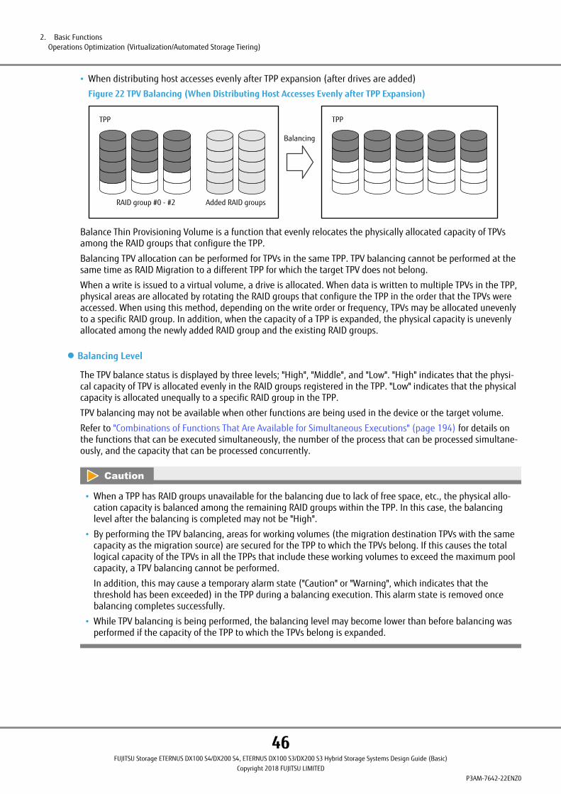
• When distributing host accesses evenly after TPP expansion (after drives are added)
Figure 22 TPV Balancing (When Distributing Host Accesses Evenly after TPP Expansion)
RAID group #0 - #2 Added RAID groups
TPP TPP
Balancing
Balance Thin Provisioning Volume is a function that evenly relocates the physically allocated capacity of TPVsamong the RAID groups that configure the TPP.
Balancing TPV allocation can be performed for TPVs in the same TPP. TPV balancing cannot be performed at thesame time as RAID Migration to a different TPP for which the target TPV does not belong.
When a write is issued to a virtual volume, a drive is allocated. When data is written to multiple TPVs in the TPP,physical areas are allocated by rotating the RAID groups that configure the TPP in the order that the TPVs wereaccessed. When using this method, depending on the write order or frequency, TPVs may be allocated unevenlyto a specific RAID group. In addition, when the capacity of a TPP is expanded, the physical capacity is unevenlyallocated among the newly added RAID group and the existing RAID groups.
● Balancing Level
The TPV balance status is displayed by three levels; "High", "Middle", and "Low". "High" indicates that the physi-cal capacity of TPV is allocated evenly in the RAID groups registered in the TPP. "Low" indicates that the physicalcapacity is allocated unequally to a specific RAID group in the TPP.
TPV balancing may not be available when other functions are being used in the device or the target volume.
Refer to "Combinations of Functions That Are Available for Simultaneous Executions" (page 194) for details onthe functions that can be executed simultaneously, the number of the process that can be processed simultane-ously, and the capacity that can be processed concurrently.
• When a TPP has RAID groups unavailable for the balancing due to lack of free space, etc., the physical allo-cation capacity is balanced among the remaining RAID groups within the TPP. In this case, the balancinglevel after the balancing is completed may not be "High".
• By performing the TPV balancing, areas for working volumes (the migration destination TPVs with the samecapacity as the migration source) are secured for the TPP to which the TPVs belong. If this causes the totallogical capacity of the TPVs in all the TPPs that include these working volumes to exceed the maximum poolcapacity, a TPV balancing cannot be performed.
In addition, this may cause a temporary alarm state ("Caution" or "Warning", which indicates that thethreshold has been exceeded) in the TPP during a balancing execution. This alarm state is removed oncebalancing completes successfully.
• While TPV balancing is being performed, the balancing level may become lower than before balancing wasperformed if the capacity of the TPP to which the TPVs belong is expanded.
2. Basic FunctionsOperations Optimization (Virtualization/Automated Storage Tiering)
46FUJITSU Storage ETERNUS DX100 S4/DX200 S4, ETERNUS DX100 S3/DX200 S3 Hybrid Storage Systems Design Guide (Basic)
Copyright 2018 FUJITSU LIMITEDP3AM-7642-22ENZ0

TPV/FTV Capacity OptimizationTPV/FTV capacity optimization can increase the unallocated areas in a pool (TPP/FTRP) by changing the physicalareas where 0 is allocated for all of the data to unallocated areas. This improves functional efficiency.
Once an area is physically allocated to a TPV/FTV, the area is never automatically released.
If operations are performed when all of the areas are physically allocated, the used areas that are recognized bya server and the areas that are actually allocated might have different sizes.
The following operations are examples of operations that create allocated physical areas with sequential data towhich only 0 is allocated:
• Restoration of data for RAW image backup
• RAID Migration from Standard volumes to TPVs/FTVs
• Creation of a file system in which writing is performed to the entire area
The TPV/FTV capacity optimization function belongs to Thin Provisioning. This function can be started after a tar-get TPV/FTV is selected via ETERNUS Web GUI or ETERNUS CLI. This function is also available when the RAID Mi-gration destination is a TPP or an FTRP.
TPV/FTV capacity optimization reads and checks the data in each allocated area for the Thin Provisioning func-tion. This function releases the allocated physical areas to unallocated areas if data that contains all zeros isdetected.
Figure 23 TPV/FTV Capacity Optimization
0 0 0 0TPV / FTV
LBA0
TPV / FTV
ReleaseReleaseReleaseRelease
: Physically allocated area (data other than ALL0 data)
: Physically allocated area (ALL0 data)
: Unallocated area
21MB (*1)
*1: The allocated capacity varies depending on the TPP/FTRP capacity.
Before the process
Check
After the process
TPV/FTV capacity optimization may not be available when other functions are being used in the device or thetarget volume.
For details on the functions that can be executed simultaneously, refer to "Combinations of Functions That AreAvailable for Simultaneous Executions" (page 194).
2. Basic FunctionsOperations Optimization (Virtualization/Automated Storage Tiering)
47FUJITSU Storage ETERNUS DX100 S4/DX200 S4, ETERNUS DX100 S3/DX200 S3 Hybrid Storage Systems Design Guide (Basic)
Copyright 2018 FUJITSU LIMITEDP3AM-7642-22ENZ0

Flexible TierThe Flexible Tier function has the following functions:
• Automated Storage Tiering
This function automatically reallocates data according to the data access frequency and optimizes perform-ance and cost.
• FTRP Balancing
I/O access to a virtual volume can be distributed among the RAID groups in a pool by relocating and balancingthe physical allocation status of the volume.
• TPV/FTV Capacity Optimization
Data in physically allocated areas are checked in blocks and unnecessary areas (areas where 0 is allocated toall of the data in each block) are released to unallocated areas.
For details on these functions, refer to "TPV/FTV Capacity Optimization" (page 47).
• QoS automation function
The QoS for each volume can be controlled by using the ETERNUS SF Storage Cruiser's QoS management op-tion.
For details on the QoS automation function, refer to the ETERNUS SF Storage Cruiser manual.
2. Basic FunctionsOperations Optimization (Virtualization/Automated Storage Tiering)
48FUJITSU Storage ETERNUS DX100 S4/DX200 S4, ETERNUS DX100 S3/DX200 S3 Hybrid Storage Systems Design Guide (Basic)
Copyright 2018 FUJITSU LIMITEDP3AM-7642-22ENZ0

Automated Storage TieringThe ETERNUS DX uses the Automated Storage Tiering function of ETERNUS SF Storage Cruiser to automaticallychange data allocation during operations according to any change in status that occurs. ETERNUS SF StorageCruiser monitors data and determines the redistribution of data. The ETERNUS DX uses the Flexible Tier functionto move data in the storage system according to requests from ETERNUS SF Storage Cruiser.
The Flexible Tier function automatically redistributes data in the ETERNUS DX according to access frequency inorder to optimize performance and reduce operation cost. Storage tiering (SSDs, SAS disks, Nearline SAS disks) isperformed by moving frequently accessed data to high speed drives such as SSDs and less frequently accesseddata to cost effective disks with large capacities. Data can be moved in blocks (252MB) that are smaller than thevolume capacity.
The data transfer unit differs depending on the chunk size. The following table shows the relationship betweenthe data transfer unit and the chunk size.
Table 17 Chunk Size and Data Transfer Unit
Chunk size Transfer unit
21MB 252MB
42MB 504MB
84MB 1,008MB
168MB 2,016MB
By using the Automated Storage Tiering function, installation costs can be reduced because Nearline SAS disk,which maintain performance, can be used.
Furthermore, because data is reallocated automatically, it can reduce the workload on the administrator for de-signing storage performance.
Figure 24 Flexible Tier
High speed SAS disk
High speed SSD
Large capacity and cheap Nearline SAS diskWork volume
Low
High
ETERNUS DX
Access frequency
Management server
ETERNUS SF Storage Cruiser
Monitors the data access frequency and optimizes performance
2. Basic FunctionsOperations Optimization (Virtualization/Automated Storage Tiering)
49FUJITSU Storage ETERNUS DX100 S4/DX200 S4, ETERNUS DX100 S3/DX200 S3 Hybrid Storage Systems Design Guide (Basic)
Copyright 2018 FUJITSU LIMITEDP3AM-7642-22ENZ0

The Flexible Tier uses pools configured by multiple RAID groups (Flexible Tier Sub Pools: FTSP) and larger poolscomprised by layers of Flexible Tier Sub Pools (Flexible Tier Pools: FTRP). A volume which is used by the FlexibleTier is referred to as the Flexible Tier Volume (FTV).
Settings and operation management for the Flexible Tier function are performed with ETERNUS SF Storage Cruis-er. For more details, refer to "ETERNUS SF Storage Cruiser Operation Guide for Optimization Option".
Figure 25 FTV Configuration
SSD SAS disk Nearline SAS disk
FTSP (High tier) FTSP (Middle tier) FTSP (Low tier)
: RAID groupFTRP (Parent pool)
Chunk
Chunk FTV
• Flexible Tier Pool (FTRP)
An FTRP is a management unit for FTSP to be layered. Up to three FTSPs can be registered in one FTRP. Thismeans that the maximum number of layers is three.
The priority orders can be set per FTSP within one FTRP. Frequently accessed data is stored in an FTSP with ahigher priority. Because FTSPs share resources with TPPs, the maximum number of FTSPs which can be createdis decreased when TPPs are created.
For data encryption, specify encryption for a pool when creating an FTRP or create an FTSP with a Self Encrypt-ing Drive (SED).
• Flexible Tier Sub Pool (FTSP)
An FTSP consists of one or more RAID groups. The FTSP capacity is expanded in units of RAID groups.
The following table shows the maximum number and the maximum capacity of FTSPs that can be registeredin an ETERNUS DX.
Table 18 The Maximum Number and the Maximum Capacity of FTSPs
Item ETERNUS DX100 S4/DX100 S3 ETERNUS DX200 S4/DX200 S3
The maximum number of Flexible Tier Pools 30 30
The maximum number of Flexible Tier Sub Pools 72 (*1) 132 (*1)
The maximum capacity of the Flexible Tier Sub Pool 2,048TB (*2)
Total capacity of the Flexible Tier Volume 2,048TB
2. Basic FunctionsOperations Optimization (Virtualization/Automated Storage Tiering)
50FUJITSU Storage ETERNUS DX100 S4/DX200 S4, ETERNUS DX100 S3/DX200 S3 Hybrid Storage Systems Design Guide (Basic)
Copyright 2018 FUJITSU LIMITEDP3AM-7642-22ENZ0

*1: The maximum total number of Thin Provisioning Pools and FTSPs.
*2: The maximum pool capacity is the capacity that combines the FTSP capacity and the Thin ProvisioningPool capacity in the ETERNUS DX. The maximum pool capacity of an FTRP is the same as the maximumpool capacity of a Flexible Tier Sub Pool.
The RAID levels and the configurations, which can be registered in the FTSP, are the same as those of a TPP.The following table shows the RAID configurations that can be registered in an FTSP.
Table 19 Levels and Configurations for a RAID Group That Can Be Registered in a FTSP
RAID level Number of configurable drives Recommended configura-tions
RAID0 4 (4D) -
RAID1 2 (1D+1M) 2 (1D+1M)
RAID1+0 4 (2D+2M), 8 (4D+4M), 16 (8D+8M), 24 (12D+12M) 8 (4D+4M)
RAID5 4 (3D+1P), 5 (4D+1P), 8 (7D+1P), 9 (8D+1P), 13 (12D+1P) 4 (3D+1P), 8 (7D+1P)
RAID6 6 (4D+2P), 8 (6D+2P), 10 (8D+2P) 8 (6D+2P)
RAID6-FR 13 ((4D+2P) ´2+1HS), 17 ((6D+2P) ´2+1HS),31 ((8D+2P) ´3+1HS), 31 ((4D+2P) ´5+1HS)
17 ((6D+2P) ´2+1HS)
• Flexible Tier Volume (FTV)
An FTV is a management unit of volumes to be layered. The maximum capacity of an FTV is 128TB. Note thatthe total capacity of FTVs must be less than the maximum capacity of FTSPs.
When creating an FTV, the Allocation method can be selected.
- Thin
When data is written from the host to an FTV, the physical area is allocated to a created virtual volume. Thephysical storage capacity can be reduced by allocating a virtualized storage capacity.
- Thick
When creating a volume, the physical area is allocated to the entire volume area. This can be used for vol-umes in the system area to prevent a system stoppage due to a pool capacity shortage during operations.
In general, selecting "Thin" is recommended. The Allocation method can be changed after an FTV is created.
Perform a TPV/FTV capacity optimization if "Thick" has changed to "Thin". By optimizing the capacity, the areathat was allocated to an FTV is released and the FTV becomes usable. If a TPV/FTV capacity optimization is notperformed, the usage of the FTV does not change even after the Allocation method is changed.
The capacity of an FTV can be expanded after it is created.
For details on the number of FTVs that can be created, refer to "Volume" (page 26).
● Threshold Monitoring of Used Capacity
When the used capacity of an FTRP or an FTV reaches the threshold, an alarm notification can be sent from ETER-NUS SF Storage Cruiser. There are two types of thresholds: "Attention" and "Warning". A different value can bespecified for each threshold type.
Make sure to add drives before free space in the FTRP runs out, and add FTSP capacity from ETERNUS SF StorageCruiser.
2. Basic FunctionsOperations Optimization (Virtualization/Automated Storage Tiering)
51FUJITSU Storage ETERNUS DX100 S4/DX200 S4, ETERNUS DX100 S3/DX200 S3 Hybrid Storage Systems Design Guide (Basic)
Copyright 2018 FUJITSU LIMITEDP3AM-7642-22ENZ0

• FTRP Thresholds
There are two FTRP usage thresholds: Attention and Warning.
Table 20 FTRP Thresholds
Threshold Selectable range Default Setting conditions
Attention 5 (%) to 80 (%) 75 (%) Attention threshold £ Warning thresholdThe "Attention" threshold can be omitted.Warning 5 (%) to 99 (%) 90 (%)
• FTV Thresholds
There is only one FTV usage threshold: Attention. If there is insufficient capacity for the FTV unallocated spacein the pool free space, an alarm notification is sent. The threshold is determined by the ratio of free space inthe FTSP and the unallocated FTV capacity.
Table 21 FTV Thresholds
Threshold Selectable range Default
Attention 1 (%) to 100 (%) 80 (%)
• When the Flexible Tier function is enabled, 32 work volumes (physical capacity is 0MB) are created. Themaximum number of volumes, which can be created in the ETERNUS DX, are reduced, depending on thenumber of these work volumes.
• If an FTSP or an FTRP includes one or more RAID groups that are configured with Advanced Format drives,the write performance may be reduced when accessing FTVs created in the relevant FTSP or FTRP from anOS or an application that does not support Advanced Format.
• The FTRP capacity that can be used for VVOLs differs from the maximum Thin Provisioning Pool capacity. Fordetails, refer to "VMware VVOL" (page 128).
2. Basic FunctionsOperations Optimization (Virtualization/Automated Storage Tiering)
52FUJITSU Storage ETERNUS DX100 S4/DX200 S4, ETERNUS DX100 S3/DX200 S3 Hybrid Storage Systems Design Guide (Basic)
Copyright 2018 FUJITSU LIMITEDP3AM-7642-22ENZ0

FTRP BalancingWhen drives are added to a pool, the physical capacity is allocated unevenly among the RAID groups in the pool.By using the Flexible Tier Pool balancing function, the allocated physical capacity as well as the usage rate ofthe physical disks in the pool can be balanced. Balancing can be performed by selecting the FTRP to be balancedin ETERNUS Web GUI and ETERNUS CLI.
Figure 26 FTRP Balancing
FTRP
FTSP#0
RAID group#0
RAID group#1
FTSP#0
RAID group#2
RAID group#3
RAID group#4
FTSP#0
RAID group#5
RAID group#6
FTRP
FTSP#0
RAID group#0
RAID group#1
FTSP#0
RAID group#2
RAID group#3
RAID group#4
FTSP#0
RAID group#5
RAID group#6
Physical capacity is balanced amongst the RAID groups in each FTSPBalancing
Added Added
FTRP balancing is a function that evenly relocates the physically allocated capacity of FTVs amongst the RAIDgroups that configure the FTSP.
Allocation of FTSPs is determined based on a performance analysis by Automated Storage Tiering function ofETERNUS SF. This plays an important role for performance. The FTRP balancing function can be used to evenlyrelocate the physically allocated capacity among RAID groups that configure the same FTSP. Note that balancingcannot be performed if balancing migrates each physical area to other FTSPs.
● Balancing Level
"High", "Middle", or "Low" is displayed for the balance level of each FTSP.
"High" indicates that the physical capacity is allocated evenly in the RAID groups registered in the FTSP. "Low"indicates that the physical capacity is allocated unequally to a specific RAID group in the FTSP.
FTRP balancing may not be available when other functions are being used in the device or the target volume.
Refer to "Combinations of Functions That Are Available for Simultaneous Executions" (page 194) for details onthe functions that can be executed simultaneously, the number of the process that can be processed simultane-ously, and the capacity that can be processed concurrently.
2. Basic FunctionsOperations Optimization (Virtualization/Automated Storage Tiering)
53FUJITSU Storage ETERNUS DX100 S4/DX200 S4, ETERNUS DX100 S3/DX200 S3 Hybrid Storage Systems Design Guide (Basic)
Copyright 2018 FUJITSU LIMITEDP3AM-7642-22ENZ0
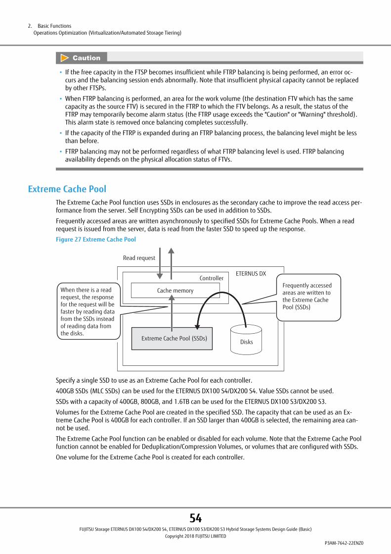
• If the free capacity in the FTSP becomes insufficient while FTRP balancing is being performed, an error oc-curs and the balancing session ends abnormally. Note that insufficient physical capacity cannot be replacedby other FTSPs.
• When FTRP balancing is performed, an area for the work volume (the destination FTV which has the samecapacity as the source FTV) is secured in the FTRP to which the FTV belongs. As a result, the status of theFTRP may temporarily become alarm status (the FTRP usage exceeds the "Caution" or "Warning" threshold).This alarm state is removed once balancing completes successfully.
• If the capacity of the FTRP is expanded during an FTRP balancing process, the balancing level might be lessthan before.
• FTRP balancing may not be performed regardless of what FTRP balancing level is used. FTRP balancingavailability depends on the physical allocation status of FTVs.
Extreme Cache PoolThe Extreme Cache Pool function uses SSDs in enclosures as the secondary cache to improve the read access per-formance from the server. Self Encrypting SSDs can be used in addition to SSDs.
Frequently accessed areas are written asynchronously to specified SSDs for Extreme Cache Pools. When a readrequest is issued from the server, data is read from the faster SSD to speed up the response.
Figure 27 Extreme Cache Pool
ETERNUS DX
Extreme Cache Pool (SSDs)
Read request
Cache memory
Controller
Disks
When there is a read request, the response for the request will be faster by reading data from the SSDs instead of reading data from the disks.
Frequently accessed areas are written to the Extreme Cache Pool (SSDs)
Specify a single SSD to use as an Extreme Cache Pool for each controller.
400GB SSDs (MLC SSDs) can be used for the ETERNUS DX100 S4/DX200 S4. Value SSDs cannot be used.
SSDs with a capacity of 400GB, 800GB, and 1.6TB can be used for the ETERNUS DX100 S3/DX200 S3.
Volumes for the Extreme Cache Pool are created in the specified SSD. The capacity that can be used as an Ex-treme Cache Pool is 400GB for each controller. If an SSD larger than 400GB is selected, the remaining area can-not be used.
The Extreme Cache Pool function can be enabled or disabled for each volume. Note that the Extreme Cache Poolfunction cannot be enabled for Deduplication/Compression Volumes, or volumes that are configured with SSDs.
One volume for the Extreme Cache Pool is created for each controller.
2. Basic FunctionsOperations Optimization (Virtualization/Automated Storage Tiering)
54FUJITSU Storage ETERNUS DX100 S4/DX200 S4, ETERNUS DX100 S3/DX200 S3 Hybrid Storage Systems Design Guide (Basic)
Copyright 2018 FUJITSU LIMITEDP3AM-7642-22ENZ0
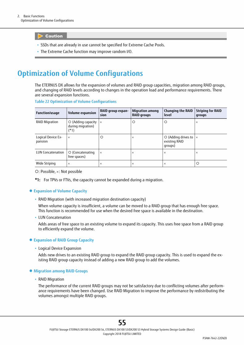
• SSDs that are already in use cannot be specified for Extreme Cache Pools.
• The Extreme Cache function may improve random I/O.
Optimization of Volume ConfigurationsThe ETERNUS DX allows for the expansion of volumes and RAID group capacities, migration among RAID groups,and changing of RAID levels according to changes in the operation load and performance requirements. Thereare several expansion functions.
Table 22 Optimization of Volume Configurations
Function/usage Volume expansion RAID group expan-sion
Migration amongRAID groups
Changing the RAIDlevel
Striping for RAIDgroups
RAID Migration ¡ (Adding capacityduring migration)(*1)
´ ¡ ¡ ´
Logical Device Ex-pansion
´ ¡ ´ ¡ (Adding drives toexisting RAIDgroups)
´
LUN Concatenation ¡ (Concatenatingfree spaces)
´ ´ ´ ´
Wide Striping ´ ´ ´ ´ ¡
¡: Possible, ´: Not possible
*1: For TPVs or FTVs, the capacity cannot be expanded during a migration.
● Expansion of Volume Capacity
• RAID Migration (with increased migration destination capacity)
When volume capacity is insufficient, a volume can be moved to a RAID group that has enough free space.This function is recommended for use when the desired free space is available in the destination.
• LUN Concatenation
Adds areas of free space to an existing volume to expand its capacity. This uses free space from a RAID groupto efficiently expand the volume.
● Expansion of RAID Group Capacity
• Logical Device Expansion
Adds new drives to an existing RAID group to expand the RAID group capacity. This is used to expand the ex-isting RAID group capacity instead of adding a new RAID group to add the volumes.
● Migration among RAID Groups
• RAID Migration
The performance of the current RAID groups may not be satisfactory due to conflicting volumes after perform-ance requirements have been changed. Use RAID Migration to improve the performance by redistributing thevolumes amongst multiple RAID groups.
2. Basic FunctionsOptimization of Volume Configurations
55FUJITSU Storage ETERNUS DX100 S4/DX200 S4, ETERNUS DX100 S3/DX200 S3 Hybrid Storage Systems Design Guide (Basic)
Copyright 2018 FUJITSU LIMITEDP3AM-7642-22ENZ0

● Changing the RAID Level
• RAID Migration (to a RAID group with a different RAID level)
Migrating to a RAID group with a different RAID level changes the RAID level of volumes. This is used to con-vert a given volume to a different RAID level.
• Logical Device Expansion (and changing RAID levels when adding the new drives)
The RAID level for RAID groups can be changed. Adding drives while changing is also available. This is used toconvert the RAID level of all the volumes belonging to a given RAID group.
● Striping for Multiple RAID Groups
• Wide Striping
Distributing a single volume to multiple RAID groups makes I/O access from the server more efficient and im-proves the performance.
2. Basic FunctionsOptimization of Volume Configurations
56FUJITSU Storage ETERNUS DX100 S4/DX200 S4, ETERNUS DX100 S3/DX200 S3 Hybrid Storage Systems Design Guide (Basic)
Copyright 2018 FUJITSU LIMITEDP3AM-7642-22ENZ0
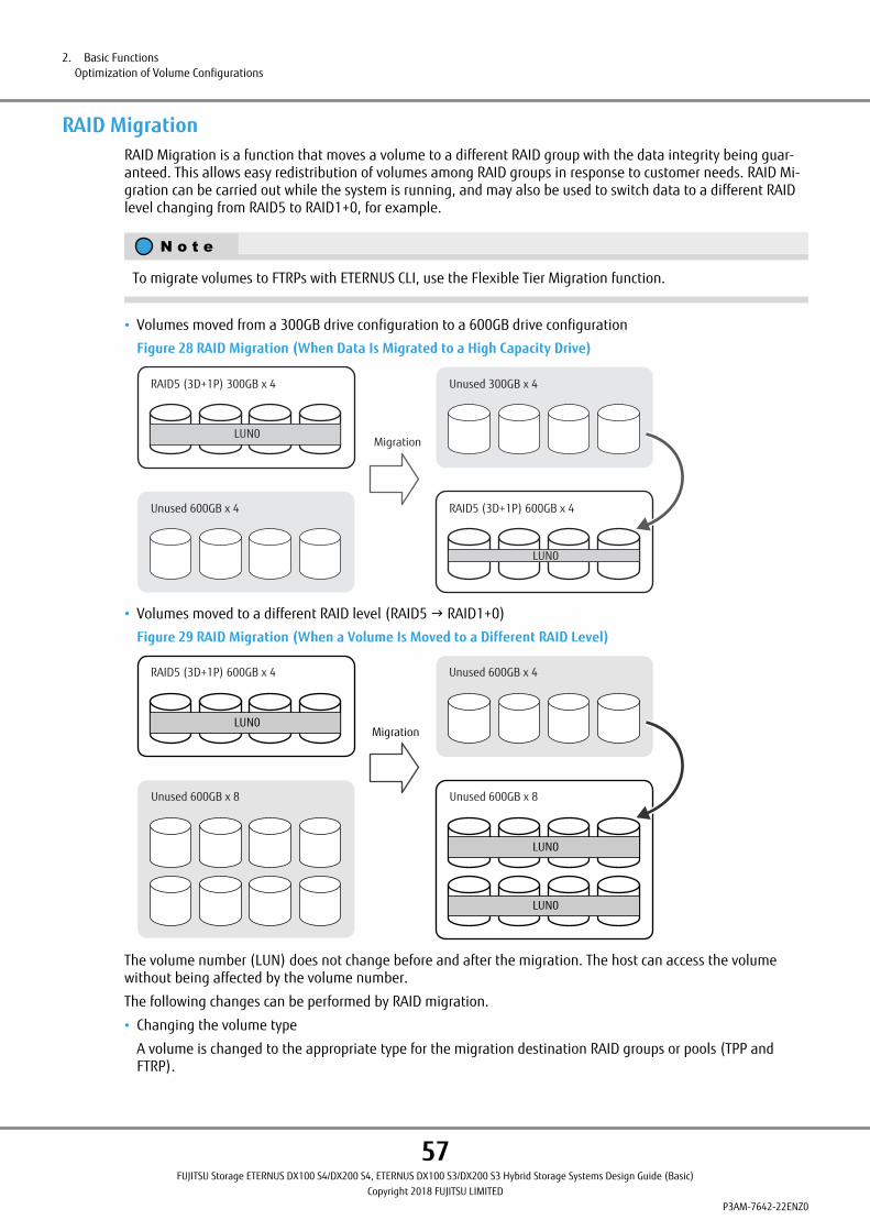
RAID MigrationRAID Migration is a function that moves a volume to a different RAID group with the data integrity being guar-anteed. This allows easy redistribution of volumes among RAID groups in response to customer needs. RAID Mi-gration can be carried out while the system is running, and may also be used to switch data to a different RAIDlevel changing from RAID5 to RAID1+0, for example.
To migrate volumes to FTRPs with ETERNUS CLI, use the Flexible Tier Migration function.
• Volumes moved from a 300GB drive configuration to a 600GB drive configuration
Figure 28 RAID Migration (When Data Is Migrated to a High Capacity Drive)
RAID5 (3D+1P) 300GB x 4
LUN0
Unused 600GB x 4
Unused 300GB x 4
RAID5 (3D+1P) 600GB x 4
LUN0
Migration
• Volumes moved to a different RAID level (RAID5 g RAID1+0)
Figure 29 RAID Migration (When a Volume Is Moved to a Different RAID Level)
LUN0Migration
LUN0
LUN0
RAID5 (3D+1P) 600GB x 4
Unused 600GB x 8
Unused 600GB x 4
Unused 600GB x 8
The volume number (LUN) does not change before and after the migration. The host can access the volumewithout being affected by the volume number.
The following changes can be performed by RAID migration.
• Changing the volume type
A volume is changed to the appropriate type for the migration destination RAID groups or pools (TPP andFTRP).
2. Basic FunctionsOptimization of Volume Configurations
57FUJITSU Storage ETERNUS DX100 S4/DX200 S4, ETERNUS DX100 S3/DX200 S3 Hybrid Storage Systems Design Guide (Basic)
Copyright 2018 FUJITSU LIMITEDP3AM-7642-22ENZ0

• Changing the encryption attributes
The encryption attribute of the volume is changed according to the encryption setting of the volume or theencryption attribute of the migration destination pool (TPP and FTRP).
• Changing the number of concatenations and the Wide Stripe Size (for WSV)
• Enabling the Deduplication/Compression function for existing volumes
The following processes can also be specified.
• Capacity expansion
When migration between RAID groups is performed, capacity expansion can also be performed at the sametime. However, the capacity cannot be expanded for TPVs or FTVs.
• TPV/FTV Capacity Optimization
When the migration destination is a pool (TPP or FTRP), TPV/FTV capacity optimization after the migration canbe set.
For details on the features of TPV/FTV capacity optimization, refer to "TPV/FTV Capacity Optimization" (page47).
Figure 30 RAID Migration
TPV (Deduplication/Compression is enabled)
TPV (Deduplication/Compression is disabled)
TPV (Deduplication/Compression is enabled)
TPV (Deduplication/Compression is disabled)
WSV
FTV FTV
WSV
Standard
Standard
The volume type depends on themigration destination.A volume becomes encryptedwhen moved to an encrypted pool.
RAID group
TPP (Encrypted)TPP (Unencrypted) FTRP (Encrypted)FTRP (Unencrypted)
:Unencrypted volumes
:Encrypted volumes
Specify unused areas in the migration destination (RAID group or pool) with a capacity larger than the migrationsource volume. Note that RAID groups that are registered as REC Disk Buffers cannot be specified as a migrationdestination.
RAID migration may not be available when other functions are being used in the ETERNUS DX or the target vol-ume.
Refer to "Combinations of Functions That Are Available for Simultaneous Executions" (page 194) for details onthe functions that can be executed simultaneously, the number of the process that can be processed simultane-ously, and the capacity that can be processed concurrently.
During RAID Migration, the access performance for the RAID groups that are specified as the RAID Migrationsource and RAID Migration destination may be reduced.
2. Basic FunctionsOptimization of Volume Configurations
58FUJITSU Storage ETERNUS DX100 S4/DX200 S4, ETERNUS DX100 S3/DX200 S3 Hybrid Storage Systems Design Guide (Basic)
Copyright 2018 FUJITSU LIMITEDP3AM-7642-22ENZ0

Logical Device ExpansionLogical Device Expansion (LDE) allows the capacity of an existing RAID group to be dynamically expanded bychanging of the RAID level or the drive configuration of the RAID group. When this function is performed, drivescan be also added at the same time. By using this LDE function to expand the capacity of an existing RAIDgroup, a new volume can be added without having to add new RAID groups.
• Expand the RAID group capacity (from RAID5(3D+1P) g RAID5(5D+1P))
Figure 31 Logical Device Expansion (When Expanding the RAID Group Capacity)
RAID5 (3D+1P) 600GB x 4
LUN0
Unused 600GB x 2
RAID5 (5D+1P) 600GB x 6Expansion
LUN0
Expands the capacity by adding two drives
• Change the RAID levels (from RAID5(3D+1P) g RAID1+0(4D+4M))
Figure 32 Logical Device Expansion (When Changing the RAID Level)
RAID5 (3D+1P) 600GB x 4
LUN0
Unused 600GB x 4
RAID1+0 (4D+4M) 600GB x 8
ExpansionLUN0
LUN0
Expands the capacity by adding four drives and changes the RAID level
LDE works in terms of RAID group units. If a target RAID group contains multiple volumes, all of the data in thevolumes is automatically redistributed when LDE is performed. Note that LDE cannot be performed if it causesthe number of data drives to be reduced in the RAID group.
In addition, LDE cannot be performed for RAID groups in which the following conditions apply.
• RAID groups that belong to TPPs or FTRPs
• The RAID group that is registered as an REC Disk Buffer
• RAID groups in which WSVs are registered
• RAID groups that are configured with RAID5+0 or RAID6-FR
LDE may not be available when other functions are being used in the ETERNUS DX or the target RAID group.
2. Basic FunctionsOptimization of Volume Configurations
59FUJITSU Storage ETERNUS DX100 S4/DX200 S4, ETERNUS DX100 S3/DX200 S3 Hybrid Storage Systems Design Guide (Basic)
Copyright 2018 FUJITSU LIMITEDP3AM-7642-22ENZ0
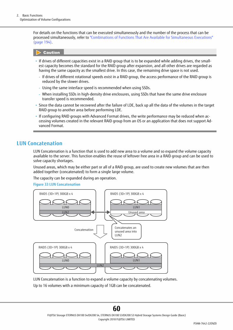
For details on the functions that can be executed simultaneously and the number of the process that can beprocessed simultaneously, refer to "Combinations of Functions That Are Available for Simultaneous Executions"(page 194).
• If drives of different capacities exist in a RAID group that is to be expanded while adding drives, the small-est capacity becomes the standard for the RAID group after expansion, and all other drives are regarded ashaving the same capacity as the smallest drive. In this case, the remaining drive space is not used.
- If drives of different rotational speeds exist in a RAID group, the access performance of the RAID group isreduced by the slower drives.
- Using the same interface speed is recommended when using SSDs.
- When installing SSDs in high-density drive enclosures, using SSDs that have the same drive enclosuretransfer speed is recommended.
• Since the data cannot be recovered after the failure of LDE, back up all the data of the volumes in the targetRAID group to another area before performing LDE.
• If configuring RAID groups with Advanced Format drives, the write performance may be reduced when ac-cessing volumes created in the relevant RAID group from an OS or an application that does not support Ad-vanced Format.
LUN ConcatenationLUN Concatenation is a function that is used to add new area to a volume and so expand the volume capacityavailable to the server. This function enables the reuse of leftover free area in a RAID group and can be used tosolve capacity shortages.
Unused areas, which may be either part or all of a RAID group, are used to create new volumes that are thenadded together (concatenated) to form a single large volume.
The capacity can be expanded during an operation.
Figure 33 LUN Concatenation
LUN0
LUN2
LUN1
RAID5 (3D+1P) 300GB x 4 RAID5 (3D+1P) 300GB x 4
LUN0
LUN2
LUN1
Unused area
LUN0
LUN2
RAID5 (3D+1P) 300GB x 4 RAID5 (3D+1P) 300GB x 4
LUN0
LUN2
LUN1
Concatenates an unused area into LUN2
Concatenation
LUN Concatenation is a function to expand a volume capacity by concatenating volumes.
Up to 16 volumes with a minimum capacity of 1GB can be concatenated.
2. Basic FunctionsOptimization of Volume Configurations
60FUJITSU Storage ETERNUS DX100 S4/DX200 S4, ETERNUS DX100 S3/DX200 S3 Hybrid Storage Systems Design Guide (Basic)
Copyright 2018 FUJITSU LIMITEDP3AM-7642-22ENZ0

Concatenation can be performed regardless of the RAID types of the concatenation source volume and the con-catenation destination volume.
When there are concatenation source volumes in SAS disks or Nearline SAS disks, concatenation can be per-formed with volumes in SAS disks or Nearline SAS disks.
For SSDs and SEDs, the drives for the concatenation source and destination volumes must be the same type (SSDor SED).
From a performance perspective, using RAID groups with the same RAID level and the same drives (type, size,capacity, and rotational speed (for disks), interface speed (for SSDs), and drive enclosure transfer speed (forSSDs)) is recommended as the concatenation source.
The same key group setting is recommended for the RAID group to which the concatenation source volumes be-long and the RAID group to which the concatenation destination volumes belong if the RAID groups are config-ured with SEDs.
A concatenated volume can be used as an OPC, EC, or QuickOPC copy source or copy destination. It can also beused as a SnapOPC/SnapOPC+ copy source.
The LUN number stays the same before and after the concatenation. Because the server-side LUNs are notchanged, an OS reboot is not required. Data can be accessed from the host in the same way regardless of theconcatenation status (before, during, or after concatenation). However, the recognition methods of the volumecapacity expansion vary depending on the OS types.
• When the concatenation source is a new volume
A new volume can be created by selecting a RAID group with unused capacity.
Figure 34 LUN Concatenation (When the Concatenation Source Is a New Volume)
Concatenation
10GB 20GB 30GB+ + 60GB
Unused area
• When expanding capacity of an existing volume
A volume can be created by concatenating an existing volume into unused capacity.
Figure 35 LUN Concatenation (When the Existing Volume Capacity Is Expanded)
10GB
20GB 30GB
+
+ 60GB
Unused area
Concatenation
Only Standard type volumes can be used for LUN Concatenation. The encryption status of a concatenated volumeis the same status as a volume that is to be concatenated.
LUN Concatenation may not be available when other functions are being used in the device or the target vol-ume.
For details on the functions that can be executed simultaneously, refer to "Combinations of Functions That AreAvailable for Simultaneous Executions" (page 194).
2. Basic FunctionsOptimization of Volume Configurations
61FUJITSU Storage ETERNUS DX100 S4/DX200 S4, ETERNUS DX100 S3/DX200 S3 Hybrid Storage Systems Design Guide (Basic)
Copyright 2018 FUJITSU LIMITEDP3AM-7642-22ENZ0

• It is recommended that the data on the volumes that are to be concatenated be backed up first.
• Refer to the applicable OS and file system documentation before dynamically expanding the volume ca-pacity because expanded volumes may not be recognized by some types and versions of server-side plat-forms (OSs).
• When a volume that is using ETERNUS SF AdvancedCopy Manager to run backups is expanded via LUN Con-catenation, the volume will need to be registered with ETERNUS SF AdvancedCopy Manager again.
• When specifying a volume in the RAID group configured with Advanced Format drives as a concatenationsource or a concatenation destination to expand the capacity, the write performance may be reduced whenaccessing the expanded volumes from an OS or an application that does not support Advanced Format.
2. Basic FunctionsOptimization of Volume Configurations
62FUJITSU Storage ETERNUS DX100 S4/DX200 S4, ETERNUS DX100 S3/DX200 S3 Hybrid Storage Systems Design Guide (Basic)
Copyright 2018 FUJITSU LIMITEDP3AM-7642-22ENZ0

Wide StripingWide Striping is a function that concatenates multiple RAID groups by striping and uses many drives simultane-ously to improve performance. This function is effective when high Random Write performance is required.
I/O accesses from the server are distributed to multiple drives by increasing the number of drives that configurea LUN, which improves the processing performance.
Figure 36 Wide Striping
Server
ETERNUS DX
CM#0 CM#1
Wide Striping creates a WSV that can be concatenated across 2 to 64 RAID groups.
The number of RAID groups that are to be concatenated is defined when creating a WSV. The number of con-catenated RAID groups cannot be changed after a WSV is created. To change the number of concatenated groupsor expand the group capacity, perform RAID Migration.
Other volumes (Standard, SDVs, SDPVs, or WSVs) can be created in the free area of a RAID group that is con-catenated by Wide Striping.
WSVs cannot be created in RAID groups with the following conditions.
• RAID groups that belong to TPPs or FTRPs
• The RAID group that is registered as an REC Disk Buffer
• RAID groups with different stripe size values
• RAID groups that are configured with different types of drives
• RAID groups that are configured with RAID6-FR
If one or more RAID groups that are configured with Advanced Format drives exist in the RAID group that is tobe concatenated by striping to create a WSV, the write performance may be reduced when accessing the cre-ated WSVs from an OS or an application that does not support Advanced Format.
2. Basic FunctionsOptimization of Volume Configurations
63FUJITSU Storage ETERNUS DX100 S4/DX200 S4, ETERNUS DX100 S3/DX200 S3 Hybrid Storage Systems Design Guide (Basic)
Copyright 2018 FUJITSU LIMITEDP3AM-7642-22ENZ0
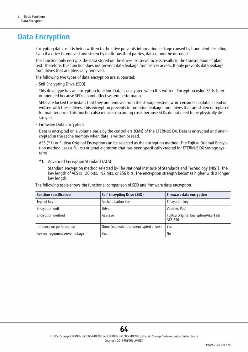
Data EncryptionEncrypting data as it is being written to the drive prevents information leakage caused by fraudulent decoding.Even if a drive is removed and stolen by malicious third parties, data cannot be decoded.
This function only encrypts the data stored on the drives, so server access results in the transmission of plaintext. Therefore, this function does not prevent data leakage from server access. It only prevents data leakagefrom drives that are physically removed.
The following two types of data encryption are supported:
• Self Encrypting Drive (SED)
This drive type has an encryption function. Data is encrypted when it is written. Encryption using SEDs is rec-ommended because SEDs do not affect system performance.
SEDs are locked the instant that they are removed from the storage system, which ensures no data is read orwritten with these drives. This encryption prevents information leakage from drives that are stolen or replacedfor maintenance. This function also reduces discarding costs because SEDs do not need to be physically de-stroyed.
• Firmware Data Encryption
Data is encrypted on a volume basis by the controllers (CMs) of the ETERNUS DX. Data is encrypted and unen-crypted in the cache memory when data is written or read.
AES (*1) or Fujitsu Original Encryption can be selected as the encryption method. The Fujitsu Original Encryp-tion method uses a Fujitsu original algorithm that has been specifically created for ETERNUS DX storage sys-tems.
*1: Advanced Encryption Standard (AES)
Standard encryption method selected by The National Institute of Standards and Technology (NIST). Thekey length of AES is 128 bits, 192 bits, or 256 bits. The encryption strength becomes higher with a longerkey length.
The following table shows the functional comparison of SED and firmware data encryption.
Function specification Self Encrypting Drive (SED) Firmware data encryption
Type of key Authentication key Encryption key
Encryption unit Drive Volume, Pool
Encryption method AES-256 Fujitsu Original Encryption/AES-128/AES-256
Influence on performance None (equivalent to unencrypted drives) Yes
Key management server linkage Yes No
2. Basic FunctionsData Encryption
64FUJITSU Storage ETERNUS DX100 S4/DX200 S4, ETERNUS DX100 S3/DX200 S3 Hybrid Storage Systems Design Guide (Basic)
Copyright 2018 FUJITSU LIMITEDP3AM-7642-22ENZ0

Encryption with Self Encrypting Drive (SED)An SED has a built-in encryption function and data can be encrypted by controlling the encryption function of anSED from the controller. An SED uses encryption keys when encrypting and storing data. Encryption keys cannotbe taken out of the drive. Furthermore, because SEDs cannot be decrypted without an authentication key, infor-mation cannot be leaked from drives which have been replaced during maintenance, even if they are not physi-cally destroyed.
Once an SED authentication key is registered to an ETERNUS DX, additional configuration on encryption is notnecessary each time a drive is added.
Data encryption by SED has no load on the controller for encryption process, and the equivalent data access per-formance to unencrypted process can be ensured.
Figure 37 Data Encryption with Self Encrypting Drives (SED)
Self-encrypting drives
Non-self-encrypting drives
Setting encryption when adding new drives is not required.
Access performance is the same as when non-encrypted drives are accessed.
ETERNUS DX
The controller performs authentication by using the authentication key that is stored in the controller or by us-ing the authentication key that is retrieved from the key server to access the drives. For the authentication keythat can be registered in the ETERNUS DX, this key can be automatically created by using the settings in ETER-NUS Web GUI or ETERNUS CLI.
By linking with the key server, the authentication key of an SED can be managed from the key server. Creatingand storing an authentication key in a key server makes it possible to manage the authentication key more se-curely.
By consolidating authentication keys for multiple ETERNUS DX storage systems in the key server, the manage-ment cost of authentication keys can be reduced.
Key management server linkage can be used with an SED authentication key operation.
Only one unique SED authentication key can be registered in each ETERNUS DX.
• The firmware data conversion encryption function cannot be used for volumes that are configured withSEDs.
• Register the SED authentication key (common key) before installing SEDs in the ETERNUS DX.
If an SED is installed without registering the SED authentication key, data leakage from the SED is possiblewhen it is physically removed.
• Only one key can be registered in each ETERNUS DX. This common key is used for all of the SEDs that areinstalled. Once the key is registered, the key cannot be changed or deleted. The common key is used toauthenticate RAID groups when key management server linkage is not used.
2. Basic FunctionsData Encryption
65FUJITSU Storage ETERNUS DX100 S4/DX200 S4, ETERNUS DX100 S3/DX200 S3 Hybrid Storage Systems Design Guide (Basic)
Copyright 2018 FUJITSU LIMITEDP3AM-7642-22ENZ0

Firmware Data EncryptionThe firmware in the ETERNUS DX has the firmware data encryption function. This function encrypts a volumewhen it is created, or converts a created volume into an encrypted volume.
Because data encryption with firmware is performed with the controller in the ETERNUS DX, the performance isdegraded, comparing with unencrypted data access.
The encryption method can be selected from the world standard AES-128, the world standard AES-256, and theFujitsu Original Encryption method. The Fujitsu Original Encryption method that is based on AES technology usesa Fujitsu original algorithm that has been specifically created for ETERNUS DX storage systems. The Fujitsu Origi-nal Encryption method has practically the same security level as AES-128 and the conversion speed for the Fujit-su Original Encryption method is faster than AES. Although AES-256 has a higher encryption strength thanAES-128, the Read/Write access performance degrades. If importance is placed upon the encryption strength,AES-256 is recommended. However, if importance is placed upon performance or if a standard encryption meth-od is not particularly required, the Fujitsu Original Encryption method is recommended.
Figure 38 Firmware Data Encryption
ETERNUS DX
Server A Server B Server C
Cannot be decodedEncrypted
Encryption setting for each LUN.
Unencrypted
Encryption is performed when data is written from the cache memory to the drive. When encrypted data is read,the data is decrypted in the cache memory. Cache memory data is not encrypted.
For Standard volumes, SDVs, SDPVs, and WSVs, encryption is performed for each volume. For TPVs and FTVs, en-cryption is performed for each pool.
2. Basic FunctionsData Encryption
66FUJITSU Storage ETERNUS DX100 S4/DX200 S4, ETERNUS DX100 S3/DX200 S3 Hybrid Storage Systems Design Guide (Basic)
Copyright 2018 FUJITSU LIMITEDP3AM-7642-22ENZ0
• The encryption method for encrypted volumes cannot be changed. Encrypted volumes cannot be changedto unencrypted volumes.
To change the encryption method or cancel the encryption for a volume, back up the data in the encryptedvolume, delete the encrypted volume, and restore the backed up data.
• If a firmware encrypted pool (TPP or FTRP) or volume exists, the encryption method cannot be changed re-gardless of whether the volume is registered to a pool.
• It is recommended that the copy source volume and the copy destination volume use the same encryptionmethod for Remote Advanced Copy between encrypted volumes.
• When copying encrypted volumes (using Advanced Copy or copy operations via server), transfer perform-ance may not be as good as when copying unencrypted volumes.
• SDPVs cannot be encrypted after they are created. To create an encrypted SDPV, set encryption when creat-ing a volume.
• TPVs cannot be encrypted individually. The encryption status of the TPVs depends on the encryption statusof the TPP to which the TPVs belong.
• FTVs cannot be encrypted individually. The encryption status of the FTVs depends on the encryption statusof the FTRP to which the FTVs belong.
• The firmware data encryption function cannot be used for volumes that are configured with SEDs.
• The volumes in a RAID6-FR RAID group cannot be converted to encrypted volumes.
When creating an encrypted volume in a RAID6-FR RAID group, specify the encryption setting when creatingthe volume.
Key Management Server LinkageSecurity for authentication keys that are used for authenticating encryption from Self Encrypting Drives (SEDs)can be enhanced by managing the authentication key in the key server.
• Key life cycle management
A key is created and stored in the key server. A key can be obtained by accessing the key server from theETERNUS DX when required. A key cannot be stored in the ETERNUS DX. Managing a key in an area that isdifferent from where an SED is stored makes it possible to manage the key more securely.
• Key management consolidation
When multiple ETERNUS DX storage systems are used, a different authentication key for each ETERNUS DX canbe stored in the key server.
The key management cost can be reduced by consolidating key management.
• Key renewal
A key is automatically renewed before it expires by setting a key expiration date. Security against informationleakage can be enhanced by regularly changing the key.
The key is automatically changed after the specified period of time. Key operation costs can be reduced bychanging the key automatically. Also, changing the key by force can be performed manually.
The following table shows functions for SED authentication keys and key management server linkage.
Table 23 Functional Comparison between the SED Authentication Key (Common Key) and Key Management Serv-er Linkage
Function SED authentication key Key Management Server Linkage
Key creation In the storage system Key server
Key storage In the storage system Key server
2. Basic FunctionsData Encryption
67FUJITSU Storage ETERNUS DX100 S4/DX200 S4, ETERNUS DX100 S3/DX200 S3 Hybrid Storage Systems Design Guide (Basic)
Copyright 2018 FUJITSU LIMITEDP3AM-7642-22ENZ0

Function SED authentication key Key Management Server Linkage
Key renewal (auto/manual) No Yes
Key compromise (*1) No Yes
Key backup No Yes
Target RAID groups RAID groups (Standard, WSV, SDV), REC Disk Buffers, SDPs, TPPs, FTRPs, andFTSPs (*2)
*1: The key becomes unavailable in the key server.
*2: The SED key group must be enabled after a pool or REC Disk Buffer is created, or after a pool capacity isexpanded.
An authentication key to access data of the RAID groups that are registered in a key group can be managed bythe key server.
RAID groups that use the same authentication key must be registered in the key group in advance.
Authentication for accessing the RAID groups that are registered in the key group is performed by acquiring thekey automatically from the key server when an ETERNUS DX is started.
As a key server for the key management server linkage, use a server that has the key management software"ETERNUS SF KM" installed. IBM Security Key Lifecycle Manager can also be used as the key management soft-ware.
Figure 39 Key Management Server Linkage
ETERNUS DX
RAID group
Global hot spare
Common key
Exclusiveauthenticationkey for a group
RAID group RAID group
Key group
Key group
Key server
Business server An ETERNUS DX uses the authentication keythat is stored in the key server in order tounlock the encryption.
SEDs (RAID group) that are not registered in a key server are encrypted by using the authentication key (com-mon key) that is stored in the ETERNUS DX.
A hot spare cannot be registered in a key group.
For Global Hot Spares, an authentication key can be specified according to the setting of the key group for theRAID groups when a Global Hot Spare is configured as a secondary drive for the RAID groups that are registeredin the key group.
For Dedicated Hot Spares, an authentication key can be specified according to the setting of the key group forthe target RAID group when a Dedicated Hot Spare is registered.
2. Basic FunctionsData Encryption
68FUJITSU Storage ETERNUS DX100 S4/DX200 S4, ETERNUS DX100 S3/DX200 S3 Hybrid Storage Systems Design Guide (Basic)
Copyright 2018 FUJITSU LIMITEDP3AM-7642-22ENZ0
• If a LAN connection cannot be secured during SED authentication, authentication fails because the authen-tication key that is managed by the key server cannot be obtained.
To use the key server linkage function, a continuous connection to the LAN must be secured.
• To use the authentication key in a key server, a key group needs to be created. Multiple RAID groups can beregistered in a key group. Note that only one key group can be created in each ETERNUS DX. One authenti-cation key can be specified for each key group. The authentication key for a key group can be changed.
• Setting a period of time for the validity of the authentication key in the key server by using the ETERNUS DXenables the key to be automatically updated by obtaining a new key from the key server before the validityof the key expires. Access from the host (server) can be maintained even if the SED authentication key ischanged during operation.
• When linking with the key management server, the ETERNUS DX obtains the SED authentication key fromthe key server and performs authentication when key management settings are performed, key manage-ment information is displayed, and any of the following operations are performed.
- Turning on the ETERNUS DX
- Expanding the RAID group capacity (Logical Device Expansion)
- Forcibly enabling a RAID group
- Creating the key group
- Recovering SEDs
- Performing maintenance of drive enclosures
- Performing maintenance of drives
- Applying disk firmware
- Registering Dedicated Hot Spares
- Rebuilding and performing copy back (when using Global Hot Spares)
- Performing a redundant copy (when using Global Hot Spares)
- Turning on the disk motor with the Eco-mode
2. Basic FunctionsData Encryption
69FUJITSU Storage ETERNUS DX100 S4/DX200 S4, ETERNUS DX100 S3/DX200 S3 Hybrid Storage Systems Design Guide (Basic)
Copyright 2018 FUJITSU LIMITEDP3AM-7642-22ENZ0
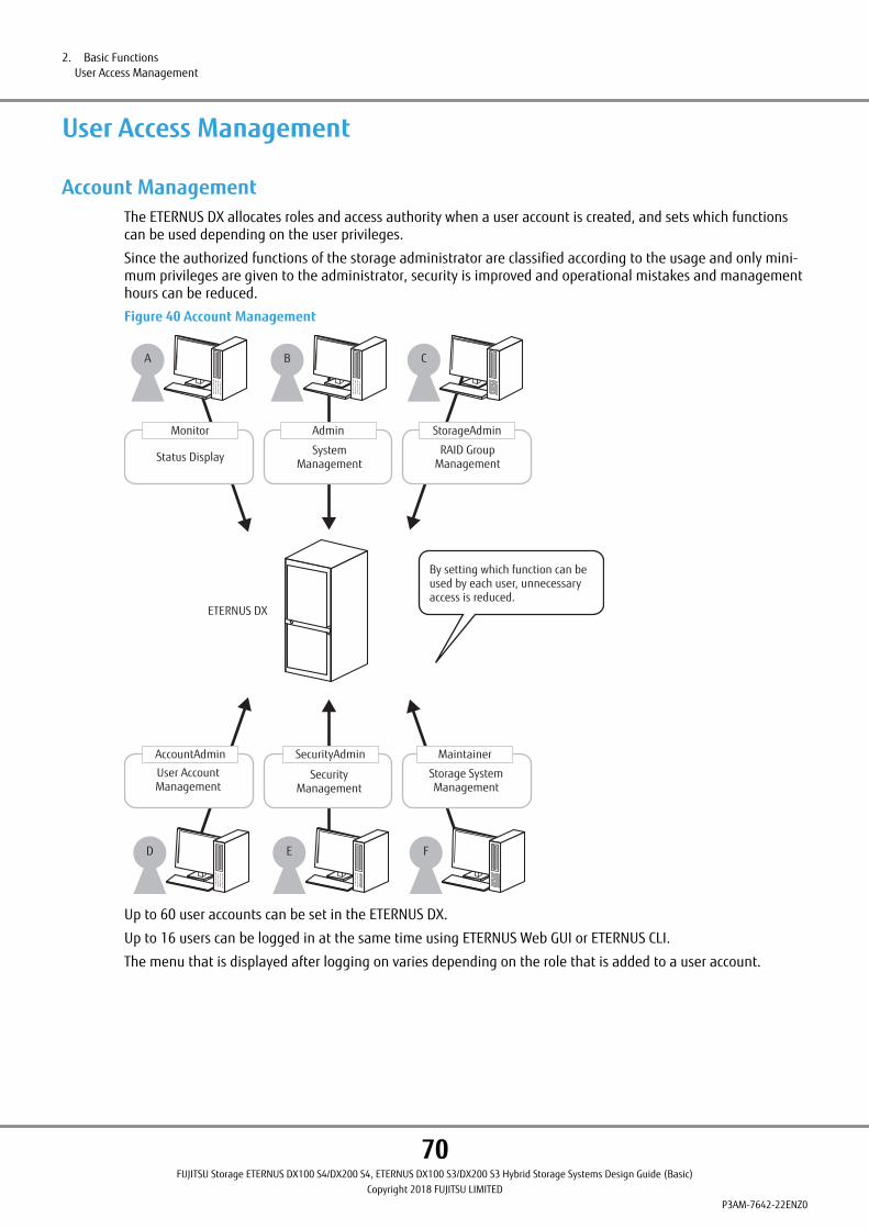
User Access Management
Account ManagementThe ETERNUS DX allocates roles and access authority when a user account is created, and sets which functionscan be used depending on the user privileges.
Since the authorized functions of the storage administrator are classified according to the usage and only mini-mum privileges are given to the administrator, security is improved and operational mistakes and managementhours can be reduced.
Figure 40 Account Management
Monitor
Status Display
Admin
System Management
StorageAdmin
RAID Group Management
Maintainer
Storage System Management
SecurityAdmin
Security Management
AccountAdmin
User Account Management
A B C
D E F
By setting which function can be used by each user, unnecessary access is reduced.
ETERNUS DX
Up to 60 user accounts can be set in the ETERNUS DX.
Up to 16 users can be logged in at the same time using ETERNUS Web GUI or ETERNUS CLI.
The menu that is displayed after logging on varies depending on the role that is added to a user account.
2. Basic FunctionsUser Access Management
70FUJITSU Storage ETERNUS DX100 S4/DX200 S4, ETERNUS DX100 S3/DX200 S3 Hybrid Storage Systems Design Guide (Basic)
Copyright 2018 FUJITSU LIMITEDP3AM-7642-22ENZ0

• Roles and available functions
Seven default roles are provided in the ETERNUS DX. The following table shows the roles and the availablefunctions (categories).
Table 24 Available Functions for Default Roles
Categories
Roles
Monitor Admin StorageAdmin
AccountAdmin
SecurityAdmin Maintainer
Software(*1)
Status Display ¡ ¡ ¡ ´ ¡ ¡ ´
RAID Group Management ´ ¡ ¡ ´ ´ ¡ ´
NAS Management ´ ¡ ¡ ´ ´ ¡ ´
Volume - Create / Modify ´ ¡ ¡ ´ ´ ¡ ´
Volume - Delete / Format ´ ¡ ¡ ´ ´ ¡ ´
Host Interface Management ´ ¡ ¡ ´ ´ ¡ ´
Advanced Copy Management ´ ¡ ¡ ´ ´ ¡ ´
Copy Session Management ´ ¡ ¡ ´ ´ ¡ ´
Storage Migration Management ´ ¡ ¡ ´ ´ ¡ ´
Storage Management ´ ¡ ´ ´ ´ ¡ ´
User Management ´ ¡ ´ ¡ ´ ´ ´
Authentication / Role ´ ¡ ´ ¡ ´ ´ ´
Security Setting ´ ¡ ´ ´ ¡ ´ ´
Maintenance Information ´ ¡ ´ ´ ¡ ¡ ´
Firmware Management ´ ¡ ´ ´ ´ ¡ ´
Maintenance Operation ´ ´ ´ ´ ´ ¡ ´
¡: Supported category ´: Not supported
*1: This is the role that is used for external software. A user account with a "Software" role cannot be usedwith ETERNUS Web GUI or ETERNUS CLI.
• To use functions that require a license, a category that supports the function used to register the requiredlicense must be selected.
• The default roles cannot be deleted or edited.
• The function categories for the roles cannot be changed.
• A role must be assigned when creating a user account.
2. Basic FunctionsUser Access Management
71FUJITSU Storage ETERNUS DX100 S4/DX200 S4, ETERNUS DX100 S3/DX200 S3 Hybrid Storage Systems Design Guide (Basic)
Copyright 2018 FUJITSU LIMITEDP3AM-7642-22ENZ0

User AuthenticationInternal Authentication and External Authentication are available as logon authentication methods. RADIUS au-thentication can be used for External Authentication.
The user authentication functions described in this section can be used when performing storage managementand operation management, and when accessing the ETERNUS DX via operation management LAN.
● Internal Authentication
Internal Authentication is performed using the authentication function of the ETERNUS DX.
The following authentication functions are available when the ETERNUS DX is connected via a LAN using opera-tion management software.
• User account authentication
User account authentication uses the user account information that is registered in the ETERNUS DX to verifyuser logins. Up to 60 user accounts can be set to access the ETERNUS DX.
• SSL authentication
ETERNUS Web GUI and SMI-S support HTTPS connections using SSL/TLS. Since data on the network is encrypted,security can be ensured. Server certifications that are required for connection are automatically created in theETERNUS DX.
• SSH authentication
Since ETERNUS CLI supports SSH connections, data that is sent or received on the network can be encrypted.The server key for SSH varies depending on the ETERNUS DX. When the server certification is updated, the serv-er key is updated as well.
Password authentication and client public key authentication are available as authentication methods for SSHconnections.
The supported client public keys are shown below.
Table 25 Client Public Key (SSH Authentication)
Type of public key Complexity (bits)
IETF style DSA for SSH v2 1024, 2048, and 4096
IETF style RSA for SSH v2 1024, 2048, and 4096
● External Authentication
External Authentication uses the user account information (user name, password, and role name) that is regis-tered on an external authentication server. RADIUS authentication supports ETERNUS Web GUI and the ETERNUSCLI login authentication for the ETERNUS DX, and authentication for connections to the ETERNUS DX through aLAN using operation management software.
• RADIUS authentication
RADIUS authentication uses the Remote Authentication Dial-In User Service (RADIUS) protocol to consolidateauthentication information for remote access.
An authentication request is sent to the RADIUS authentication server that is outside the ETERNUS system net-work. The authentication method can be selected from CHAP and PAP. Two RADIUS authentication servers (theprimary server and the secondary server) can be connected to balance user account information and to createa redundant configuration. When the primary RADIUS server failed to authenticate, the secondary RADIUSserver attempts to authenticate.
2. Basic FunctionsUser Access Management
72FUJITSU Storage ETERNUS DX100 S4/DX200 S4, ETERNUS DX100 S3/DX200 S3 Hybrid Storage Systems Design Guide (Basic)
Copyright 2018 FUJITSU LIMITEDP3AM-7642-22ENZ0

User roles are specified in the Vendor Specific Attribute (VSA) of the Access-Accept response from the server.The following table shows the syntax of the VSA based account role on the RADIUS server.
ItemSize(octets)
Value Description
Type 1 26 Attribute number for the Vendor Specific At-tribute
Length 1 7 or more Attribute size (calculated by server)
Vendor-Id 4 211 Fujitsu Limited (SMI Private Enterprise Code)
Vendor type 1 1 Eternus-Auth-Role
Vendor length 1 2 or more Attribute size described after Vendor type(calculated by server)
Attribute-Specific 1 or more ASCII characters One or more assignable role names for suc-cessfully authenticated users (*1)
*1: The server-side role names must be identical to the role names of the ETERNUS DX. Match the letter casewhen entering the role names.
[Example] RoleName0
• If RADIUS authentication fails when "Do not use Internal Authentication" has been selected for "Authentica-tion Error Recovery" on ETERNUS Web GUI, ETERNUS CLI, or SMI-S, logging on to ETERNUS Web GUI or ETER-NUS CLI will not be available.
When the setting to use Internal Authentication for errors caused by network problems is configured, Inter-nal Authentication is performed if RADIUS authentication fails on both primary and secondary RADIUS serv-ers, or at least one of these failures is due to network error.
• So long as there is no RADIUS authentication response the ETERNUS DX will keep retrying to authenticatethe user for the entire "Timeout" period set on the "Set RADIUS Authentication (Initial)" menu. If authentica-tion does not succeed before the "Timeout" period expires, RADIUS Authentication is considered to be a fail-ure.
• When using RADIUS authentication, if the role that is received from the server is unknown (not set) for thedevice, RADIUS authentication fails.
2. Basic FunctionsUser Access Management
73FUJITSU Storage ETERNUS DX100 S4/DX200 S4, ETERNUS DX100 S3/DX200 S3 Hybrid Storage Systems Design Guide (Basic)
Copyright 2018 FUJITSU LIMITEDP3AM-7642-22ENZ0

Audit LogThe ETERNUS DX can send information such as access records by the administrator and setting changes as auditlogs to the Syslog servers.
Audit logs are audit trail information that record operations that are executed for the ETERNUS DX and the re-sponse from the system. This information is required for auditing.
The audit log function enables monitoring of all operations and any unauthorized access that may affect thesystem.
Syslog protocols (RFC3164 and RFC5424) are supported for audit logs.
Information that is to be sent is not saved in the ETERNUS DX and the Syslog protocols are used to send out theinformation. Two Syslog servers can be set as the destination servers in addition to the Syslog server that is usedfor event notification.
Figure 41 Audit Log
Syslog serverETERNUS DX
System administrator
Log in
Log out
Change settings↓
↓
Information such asthe storage system name,the user/role,the process time,the process details,and the process results
Audit log
2. Basic FunctionsUser Access Management
74FUJITSU Storage ETERNUS DX100 S4/DX200 S4, ETERNUS DX100 S3/DX200 S3 Hybrid Storage Systems Design Guide (Basic)
Copyright 2018 FUJITSU LIMITEDP3AM-7642-22ENZ0
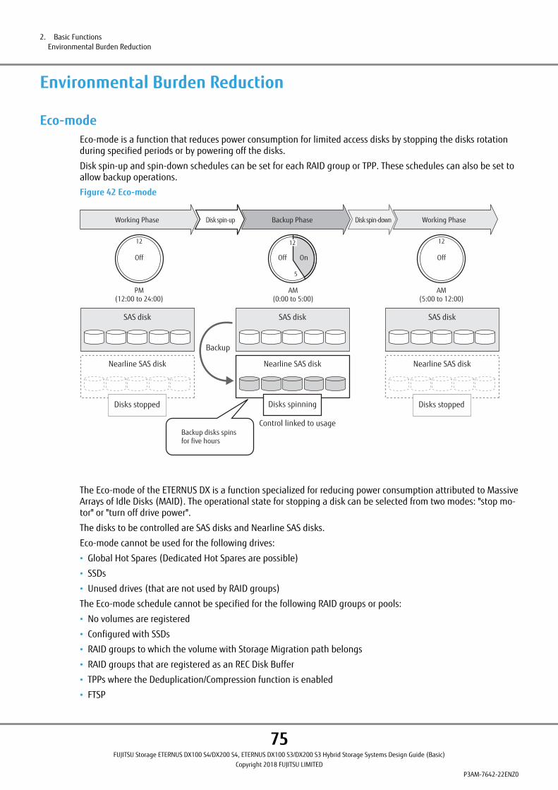
Environmental Burden Reduction
Eco-modeEco-mode is a function that reduces power consumption for limited access disks by stopping the disks rotationduring specified periods or by powering off the disks.
Disk spin-up and spin-down schedules can be set for each RAID group or TPP. These schedules can also be set toallow backup operations.
Figure 42 Eco-mode
SAS disk
Nearline SAS disk
SAS disk
Nearline SAS disk
SAS disk
Nearline SAS disk
Disks spinning Disks stoppedDisks stopped
Control linked to usage
Working Phase Disk spin-up Disk spin-downBackup Phase
Backup
AM(0:00 to 5:00)
5
PM(12:00 to 24:00)
12
Off
12
OffOff
12
On
AM(5:00 to 12:00)
Backup disks spins for five hours
Working Phase
The Eco-mode of the ETERNUS DX is a function specialized for reducing power consumption attributed to MassiveArrays of Idle Disks (MAID). The operational state for stopping a disk can be selected from two modes: "stop mo-tor" or "turn off drive power".
The disks to be controlled are SAS disks and Nearline SAS disks.
Eco-mode cannot be used for the following drives:
• Global Hot Spares (Dedicated Hot Spares are possible)
• SSDs
• Unused drives (that are not used by RAID groups)
The Eco-mode schedule cannot be specified for the following RAID groups or pools:
• No volumes are registered
• Configured with SSDs
• RAID groups to which the volume with Storage Migration path belongs
• RAID groups that are registered as an REC Disk Buffer
• TPPs where the Deduplication/Compression function is enabled
• FTSP
2. Basic FunctionsEnvironmental Burden Reduction
75FUJITSU Storage ETERNUS DX100 S4/DX200 S4, ETERNUS DX100 S3/DX200 S3 Hybrid Storage Systems Design Guide (Basic)
Copyright 2018 FUJITSU LIMITEDP3AM-7642-22ENZ0

• FTRP
For RAID groups with the following conditions, the Eco-mode schedule can be set but the disks motor cannot bestopped or the power supply cannot be turned off:
• SDPVs are registered
• ODX Buffer volumes are registered
If disk access occurs while the disk motor is stopped, the disk is immediately spun up and can be accessed withinone to five minutes.
The Eco-mode function can be used with the following methods:
• Schedule control
Controls the disk motors by configuring the Eco-mode schedule on ETERNUS Web GUI or ETERNUS CLI. The op-eration time schedule settings/management is performed for each RAID group and TPP.
• External application control (software interaction control)
Disk motor is controlled for each RAID group on ETERNUS SF Software.
The disk motors are controlled by interacting with applications installed on the server side and responding toinstructions from the applications. Applications which can be interacted with are as follows:
- ETERNUS SF Storage Cruiser
- ETERNUS SF AdvancedCopy Manager
The following hierarchical storage management software can be also linked with Eco-mode.
When using the Eco-mode function with these products, an Eco-mode disk operating schedule does not need tobe set. A drive in a stopped condition starts running when it is accessed.
• IBM Tivoli Storage Manager for Space Management
• IBM Tivoli Storage Manager HSM for Windows
• Symantec Veritas Storage Foundation Dynamic Storage Tiering (DST) function
The following table shows the specifications of Eco-mode.
Table 26 Eco-mode Specifications
Item Description Remarks
Number of registrable schedules 64 Up to 8 events (during disk operation) can be set for eachschedule.
Host I/O Monitoring Interval (*1) 30 minutes (default) Monitoring time can be set from 10 to 60 minutes.The monitoring interval setting can be changed by userswith the maintenance operation privilege.
Disk Motor Spin-down Limit Count(per day)
25 (default) The number of times the disk is stopped can be set from1 to 25.When it exceeds the upper limit, Eco-mode becomes un-available, and the disks keep running.
Target drive SAS disks (*2)Nearline SAS disks
SSD is not supported.
*1: The monitoring time period to check if there is no access to a disk for a given length of time and stop thedrive.
*2: Self Encrypting Drives (SEDs) are also included.
2. Basic FunctionsEnvironmental Burden Reduction
76FUJITSU Storage ETERNUS DX100 S4/DX200 S4, ETERNUS DX100 S3/DX200 S3 Hybrid Storage Systems Design Guide (Basic)
Copyright 2018 FUJITSU LIMITEDP3AM-7642-22ENZ0

• To set Eco-mode schedule, use ETERNUS Web GUI, ETERNUS CLI, ETERNUS SF Storage Cruiser, or ETERNUS SFAdvancedCopy Manager. Note that schedules that are created by ETERNUS Web GUI or ETERNUS CLI andschedules that are created by ETERNUS SF Storage Cruiser or ETERNUS SF AdvancedCopy Manager cannot beshared. Make sure to use only one type of software to manage a RAID group.
• Use ETERNUS Web GUI or ETERNUS CLI to set Eco-mode for TPPs. ETERNUS SF Storage Cruiser or ETERNUS SFAdvancedCopy Manager cannot be used to set the Eco-mode for TPPs and FTRPs.
• Specify the same Eco-mode schedule for the RAID groups that configure a WSV. If different Eco-mode sched-ules are specified, activation of stopped disks when host access is performed occurs and the response timemay increase.
• The operation time of disks varies depending on the Eco-mode schedule and the disk access.
- Access to a stopped disk outside of the scheduled operation time period causes the motor of the stoppeddisk to be spun up, allowing normal access in about one to five minutes. When a set time elapses sincethe last access to a disk, the motor of the disk is stopped.
- If a disk is activated from the stopped state more than a set amount of times in a day, the Eco-modeschedule is not applied and disk motors are not stopped by the Eco-mode.
(Example 1) Setting the Eco-mode schedule via ETERNUS Web GUI
Operation schedule is set as 9:00 to 21:00 and there are no accesses outside of the scheduled period
21:009:001:00 0:00
Stop Stop
The disk stops 10 minafter the scheduled operation
The motor starts rotating 10 min before the scheduled operation
Operation
Scheduled operation
(Example 2) Setting the Eco-mode schedule via ETERNUS Web GUI
Operation schedule is set as 9:00 to 21:00 and there are accesses outside of the scheduled period
StopScheduled operation Stop Operation
21:009:001:00
OperationOperation
AccessStop accessing
The disk stops 10 min after the scheduled operation
Accessible in 1 to 5 min
The motor starts rotating 10 min before the scheduled operation
2. Basic FunctionsEnvironmental Burden Reduction
77FUJITSU Storage ETERNUS DX100 S4/DX200 S4, ETERNUS DX100 S3/DX200 S3 Hybrid Storage Systems Design Guide (Basic)
Copyright 2018 FUJITSU LIMITEDP3AM-7642-22ENZ0

• Eco-mode schedules are executed according to the date and time that are set in the ETERNUS DX. To turnon and turn off the disk motors according to the schedule that is set, use the Network Time Protocol (NTP)server in the date and time setting in ETERNUS Web GUI to set automatic adjustment of the date and time.
• If the number of drives that are activated in a single drive enclosure is increased, the time for system activa-tion may take longer (about 1 to 5 minutes). This is because all of the disks cannot be activated at thesame time.
• Even if the disk motor is turned on and off repeatedly according to the Eco-mode schedule, the failure rateis not affected comparing to the case when the motor is always on.
Power Consumption VisualizationThe power consumption and the temperature of the ETERNUS DX can be visualized with a graph by using theETERNUS SF Storage Cruiser integrated management software in a storage system environment. The ETERNUSDX collects information on power consumption and the ambient temperature in the storage system. Collectedinformation is notified using SNMP and graphically displayed on the screens by ETERNUS SF Storage Cruiser.Cooling efficiency can be improved by understanding local temperature rises in the data center and reviewingthe location of air-conditioning.
Understanding the drives that have a specific time to be used from the access frequency to RAID groups enablesthe Eco-mode schedule to be adjusted accordingly.
Figure 43 Power Consumption Visualization
Power consumption
Collects power consumption and temperature data for each storage system.
ETERNUS DX storage systems
Server
Temperature
ETERNUS SF Storage Cruiser
2. Basic FunctionsEnvironmental Burden Reduction
78FUJITSU Storage ETERNUS DX100 S4/DX200 S4, ETERNUS DX100 S3/DX200 S3 Hybrid Storage Systems Design Guide (Basic)
Copyright 2018 FUJITSU LIMITEDP3AM-7642-22ENZ0

Operation Management/Device Monitoring
Operation Management InterfaceOperation management software can be selected in the ETERNUS DX according to the environment of the user.
ETERNUS Web GUI and ETERNUS CLI are embedded in the ETERNUS DX controllers.
Shared folder (NFS and CIFS) operations can be performed with ETERNUS Web GUI or ETERNUS CLI for the NASenvironment settings.
The setting and display functions can also be used with ETERNUS SF Web Console.
■ ETERNUS Web GUI
ETERNUS Web GUI is a program for settings and operation management that is embedded in the ETERNUS DXand accessed by using a web browser via http or https.
ETERNUS Web GUI has an easy-to-use design that makes intuitive operation possible.
The settings that are required for the ETERNUS DX initial installation can be easily performed by following thewizard and inputting the parameters for the displayed setting items.
SSL v3 and TLS are supported for https connections. However, when using https connections, it is required toregister a server certification in advance or self-generate a server certification. Self-generated server certifica-tions are not already certified with an official certification authority registered in web browsers. Therefore, someweb browsers will display warnings. Once a server certification is installed in a web browser, the warning will notbe displayed again.
When using ETERNUS Web GUI to manage operations, prepare a Web browser in the administration terminal.The following table shows the supported Web browsers.
Table 27 ETERNUS Web GUI Operating Environment
Software Guaranteed operating environment
Web browser Microsoft Internet Explorer 9.0, 10.0 (desktop version), 11.0 (desktop version)
Mozilla Firefox ESR 45, ESR 52
When using ETERNUS Web GUI to connect the ETERNUS DX, the default port number is 80 for http.
■ ETERNUS CLI
ETERNUS CLI supports Telnet or SSH connections. The ETERNUS DX can be configured and monitored using com-mands and command scripts.
With the ETERNUS CLI, SSH v2 encrypted connections can be used. SSH server keys differ for each storage system,and must be generated by the SSH server before using SSH.
Password authentication and client public key authentication are supported as authentication methods for SSH.
For details on supported client public key types, refer to "User Authentication" (page 72).
2. Basic FunctionsOperation Management/Device Monitoring
79FUJITSU Storage ETERNUS DX100 S4/DX200 S4, ETERNUS DX100 S3/DX200 S3 Hybrid Storage Systems Design Guide (Basic)
Copyright 2018 FUJITSU LIMITEDP3AM-7642-22ENZ0

■ ETERNUS SF
ETERNUS SF can manage a Fujitsu storage products centered storage environment. An easy-to-use interface ena-bles complicated storage environment design and setting operations, which allows easy installation of a storagesystem without needing to have high level skills.
ETERNUS SF ensures stable operation by managing the entire storage environment.
With ETERNUS SF Storage Cruiser, integrated operation management for both SAN and NAS is possible.
■ SMI-S
Storage systems can be managed collectively using the general storage management application that supportsVersion 1.6 of Storage Management Initiative Specification (SMI-S). SMI-S is a storage management interfacestandard of the Storage Network Industry Association (SNIA). SMI-S can monitor the ETERNUS DX status andchange configurations such as RAID groups, volumes, and Advanced Copy (EC/REC/OPC/SnapOPC/SnapOPC+).
Performance Information ManagementThe ETERNUS DX supports a function that collects and displays the performance data of the storage system viaETERNUS Web GUI or ETERNUS CLI. The collected performance information shows the operation status and loadstatus of the ETERNUS DX and can be used to optimize the system configuration.
ETERNUS SF Storage Cruiser can be used to easily understand the operation status and load status of the ETER-NUS DX by graphically displaying the collected information on the GUI. ETERNUS SF Storage Cruiser can alsomonitor the performance threshold and retain performance information for the duration that a user specifies.
When performance monitoring is operated from ETERNUS SF Storage Cruiser, ETERNUS Web GUI, or ETERNUS CLI,performance information in each type is obtained during specified intervals (30 - 300 seconds) in the ETERNUSDX.
The performance information can be stored and exported in the text file format, as well as displayed, from ETER-NUS Web GUI. The performance information, which can be obtained, are indicated as follows.
● Volume Performance Information for Host I/O
• Read IOPS (the read count per second)
• Write IOPS (the write count per second)
• Read Throughput (the amount of transferred data that is read per second)
• Write Throughput (the amount of transferred data that is written per second)
• Read Response Time (the average response time per host I/O during a read)
• Write Response Time (the average response time per host I/O during a write)
• Read Process Time (the average process time in the storage system per host I/O during a read)
• Write Process Time (the average process time in the storage system per host I/O during a write)
• Read Cache Hit Rate (cache hit rate for read)
• Write Cache Hit Rate (cache hit rate for write)
• Prefetch Cache Hit Rate (cache hit rate for prefetch)
● Volume Performance Information for the Advanced Copy Function
• Read IOPS (the read count per second)
• Write IOPS (the write count per second)
• Read Throughput (the amount of transferred data that is read per second)
2. Basic FunctionsOperation Management/Device Monitoring
80FUJITSU Storage ETERNUS DX100 S4/DX200 S4, ETERNUS DX100 S3/DX200 S3 Hybrid Storage Systems Design Guide (Basic)
Copyright 2018 FUJITSU LIMITEDP3AM-7642-22ENZ0

• Write Throughput (the amount of transferred data that is written per second)
• Read Cache Hit Rate (cache hit rate for read)
• Write Cache Hit Rate (cache hit rate for write)
• Prefetch Cache Hit Rate (cache hit rate for prefetch)
● Controller Performance Information
• Busy Ratio (CPU usage)
• CPU core usage
● CA Port Performance Information
• Read IOPS (the read count per second)
• Write IOPS (the write count per second)
• Read Throughput (the amount of transferred data that is read per second)
• Write Throughput (the amount of transferred data that is written per second)
● RA Port Performance Information
• Send IOPS (the number of data transmission per second)
• Receive IOPS (the number of times data is received per second)
• Send throughput (the amount of transferred data that is sent per second)
• Receive throughput (the amount of transferred data that is received per second)
● Host-LU QoS Performance Information
• Average IOPS (the average number of I/Os per second)
• Minimum IOPS (the minimum number of I/Os per second)
• Maximum IOPS (the maximum number of I/Os per second)
• Average throughput (average MB/s value)
• Minimum throughput (minimum MB/s value)
• Maximum throughput (maximum MB/s value)
• Total delay time (total delay time of commands by QoS control)
• Average delay time (average delay time per command by QoS control)
● Drive Performance Information
• Busy Ratio (drive usage)
• When the ETERNUS DX is rebooted, the performance monitoring process is stopped.
• If performance monitoring is started from ETERNUS SF Storage Cruiser, ETERNUS Web GUI or ETERNUS CLIcannot stop the process.
• If performance monitoring is started from ETERNUS Web GUI or ETERNUS CLI, the process can be stoppedfrom ETERNUS SF Storage Cruiser.
2. Basic FunctionsOperation Management/Device Monitoring
81FUJITSU Storage ETERNUS DX100 S4/DX200 S4, ETERNUS DX100 S3/DX200 S3 Hybrid Storage Systems Design Guide (Basic)
Copyright 2018 FUJITSU LIMITEDP3AM-7642-22ENZ0

Event NotificationWhen an error occurs in the ETERNUS DX, the event notification function notifies the event information to theadministrator. The administrator can be informed that an error occurred without monitoring the screen all thetime.
The methods to notify an event are e-mail, SNMP Trap, syslog, remote support, and host sense.
Figure 44 Event Notification
SNMPmanager
Mail server
Syslog server
Remotesupportcenter
REMCS/AIS Connect
Host sense
Server (host)
syslogSNMP TrapE-mail
ETERNUS DX
The notification methods and levels can be set as required.
The following events are notified.
Table 28 Levels and Contents of Events That Are Notified
Level Level of importance Event contents
Error Maintenance is necessary Component failure, temperature error, end ofbattery life (*1), rebuild/copyback, etc.
Warning Preventive maintenance is neces-sary
Module warning, battery life warning (*1),etc.
Notification (information) Device information Component restoration notification, user log-in/logout, RAID creation/deletion, storagesystem power on/off, firmware update, etc.
*1: Battery related events are notified only for the ETERNUS DX100 S4/DX200 S4.
When an event occurs, an e-mail is sent to the specified e-mail address.
The ETERNUS DX supports "SMTP AUTH" and "SMTP over SSL" as user authentication. A method can be selectedfrom CRAM-MD5, PLAIN, LOGIN, or AUTO which automatically selects one of these methods.
2. Basic FunctionsOperation Management/Device Monitoring
82FUJITSU Storage ETERNUS DX100 S4/DX200 S4, ETERNUS DX100 S3/DX200 S3 Hybrid Storage Systems Design Guide (Basic)
Copyright 2018 FUJITSU LIMITEDP3AM-7642-22ENZ0

● Simple Network Management Protocol (SNMP)
Using the SNMP agent function, management information is sent to the SNMP manager (network management/monitoring server).
The ETERNUS DX supports the following SNMP specifications.
Table 29 SNMP Specifications
Item Specification Remarks
SNMP version SNMP v1, v2c, v3 —
MIB MIB II Only the information managed by the ETERNUS DX canbe sent with the GET command.
The SET command send operation is not supported.
FibreAlliance MIB 2.2 This is a MIB which is defined for the purpose of FC baseSAN management.
Only the information managed by the ETERNUS DX canbe sent with the GET command.
The SET command send operation is not supported.
Unique MIB This is a MIB in regard to hardware configuration of theETERNUS DX.
Trap Unique Trap A trap number is defined for each category (such as acomponent disconnection and a sensor error) and a mes-sage with a brief description of an event as additional in-formation is provided.
● Syslog
By registering the syslog destination server in the ETERNUS DX, various events that are detected by the ETERNUSDX are sent to the syslog server as event logs.
The ETERNUS DX supports the syslog protocol which conforms to RFC3164 and RFC5424.
● Remote Support
The errors that occur in the ETERNUS DX are notified to the remote support center. The ETERNUS DX sends addi-tional information (logs and system configuration information) for checking the error. This shortens the time tocollect information.
Remote support has the following maintenance functions.
• Failure notice
This function reports various failures, that occur in the ETERNUS DX, to the remote support center. The mainte-nance engineer is notified of a failure immediately.
• Information transfer
This function sends information such as logs and configuration information to be used when checking a fail-ure. This shortens the time to collect the information that is necessary to check errors.
• Firmware download
The latest firmware in the remote support center is automatically registered in the ETERNUS DX. This functionensures that the latest firmware is registered in the ETERNUS DX, and prevents known errors from occurring.Firmware can also be registered manually.
However, NAS system firmware is not automatically downloaded.
2. Basic FunctionsOperation Management/Device Monitoring
83FUJITSU Storage ETERNUS DX100 S4/DX200 S4, ETERNUS DX100 S3/DX200 S3 Hybrid Storage Systems Design Guide (Basic)
Copyright 2018 FUJITSU LIMITEDP3AM-7642-22ENZ0

● Host Sense
The ETERNUS DX returns host senses (sense codes) to notify specific status to the server. Detailed informationsuch as error contents can be obtained from the sense code.
• Note that the ETERNUS DX cannot check whether the event log is successfully sent to the syslog server. Evenif a communication error occurs between the ETERNUS DX and the syslog server, event logs are not sentagain. When using the syslog function (enabling the syslog function) for the first time, confirm that thesyslog server has successfully received the event log of the relevant operation.
• Using the ETERNUS Multipath Driver to monitor the storage system by host senses is recommended.
Sense codes that cannot be detected in a single configuration can also be reported.
2. Basic FunctionsOperation Management/Device Monitoring
84FUJITSU Storage ETERNUS DX100 S4/DX200 S4, ETERNUS DX100 S3/DX200 S3 Hybrid Storage Systems Design Guide (Basic)
Copyright 2018 FUJITSU LIMITEDP3AM-7642-22ENZ0

Device Time SynchronizationThe ETERNUS DX treats the time that is specified in the Master CM as the system standard time and distributesthat time to other modules to synchronize the storage time. The ETERNUS DX also supports the time correctionfunction by using the Network Time Protocol (NTP). The ETERNUS DX corrects the system time by obtaining thetime information from the NTP server during regular time correction.
The ETERNUS DX has a clock function and manages time information of date/time and the time zone (the regionin which the ETERNUS DX is installed). This time information is used for internal logs and for functions such asEco-mode, remote copy, and remote support.
The automatic time correction by NTP is recommended to synchronize time in the whole system.
When using the NTP, specify the NTP server or the SNTP server. The ETERNUS DX supports NTP protocol v4. Thetime correction mode is Step mode (immediate correction). The time is regularly corrected every three hoursonce the NTP is set.
• If an error occurs in a system that has a different date and time for each device, analyzing the cause of thiserror may be difficult.
• Make sure to set the date and time correctly when using Eco-mode.
The stop and start process of the disk motors does not operate according to the Eco-mode schedule if thedate and time in the ETERNUS DX are not correct.
Using NTP to synchronize the time in the ETERNUS DX and the servers is recommended.
Figure 45 Device Time Synchronization
NTP server
ETERNUS DX
Daylight Saving Time
Date and Time
Time Zone
yyyy mm dd xx:xx:xx
GMT + 09.00
NTP
2. Basic FunctionsOperation Management/Device Monitoring
85FUJITSU Storage ETERNUS DX100 S4/DX200 S4, ETERNUS DX100 S3/DX200 S3 Hybrid Storage Systems Design Guide (Basic)
Copyright 2018 FUJITSU LIMITEDP3AM-7642-22ENZ0
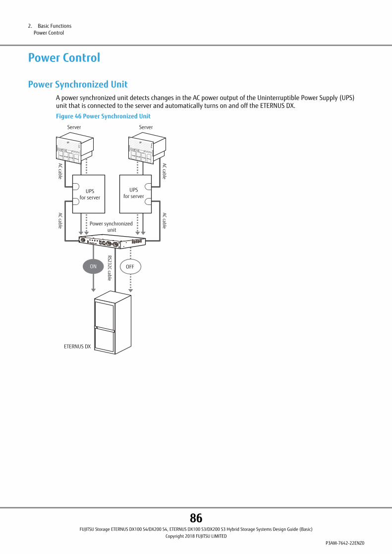
Power Control
Power Synchronized UnitA power synchronized unit detects changes in the AC power output of the Uninterruptible Power Supply (UPS)unit that is connected to the server and automatically turns on and off the ETERNUS DX.
Figure 46 Power Synchronized Unit
RS232C cable
ServerServer
Power synchronized unit
ETERNUS DX
OFF
UPS for server
UPS for server
ON
AC cableAC cable
AC cableAC cable
2. Basic FunctionsPower Control
86FUJITSU Storage ETERNUS DX100 S4/DX200 S4, ETERNUS DX100 S3/DX200 S3 Hybrid Storage Systems Design Guide (Basic)
Copyright 2018 FUJITSU LIMITEDP3AM-7642-22ENZ0
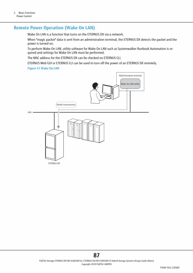
Remote Power Operation (Wake On LAN)Wake On LAN is a function that turns on the ETERNUS DX via a network.
When "magic packet" data is sent from an administration terminal, the ETERNUS DX detects the packet and thepower is turned on.
To perform Wake On LAN, utility software for Wake On LAN such as Systemwalker Runbook Automation is re-quired and settings for Wake On LAN must be performed.
The MAC address for the ETERNUS DX can be checked on ETERNUS CLI.
ETERNUS Web GUI or ETERNUS CLI can be used to turn off the power of an ETERNUS DX remotely.
Figure 47 Wake On LAN
LAN
Packet transmission
Administration terminal
Wake On LAN utility
ETERNUS DX
2. Basic FunctionsPower Control
87FUJITSU Storage ETERNUS DX100 S4/DX200 S4, ETERNUS DX100 S3/DX200 S3 Hybrid Storage Systems Design Guide (Basic)
Copyright 2018 FUJITSU LIMITEDP3AM-7642-22ENZ0
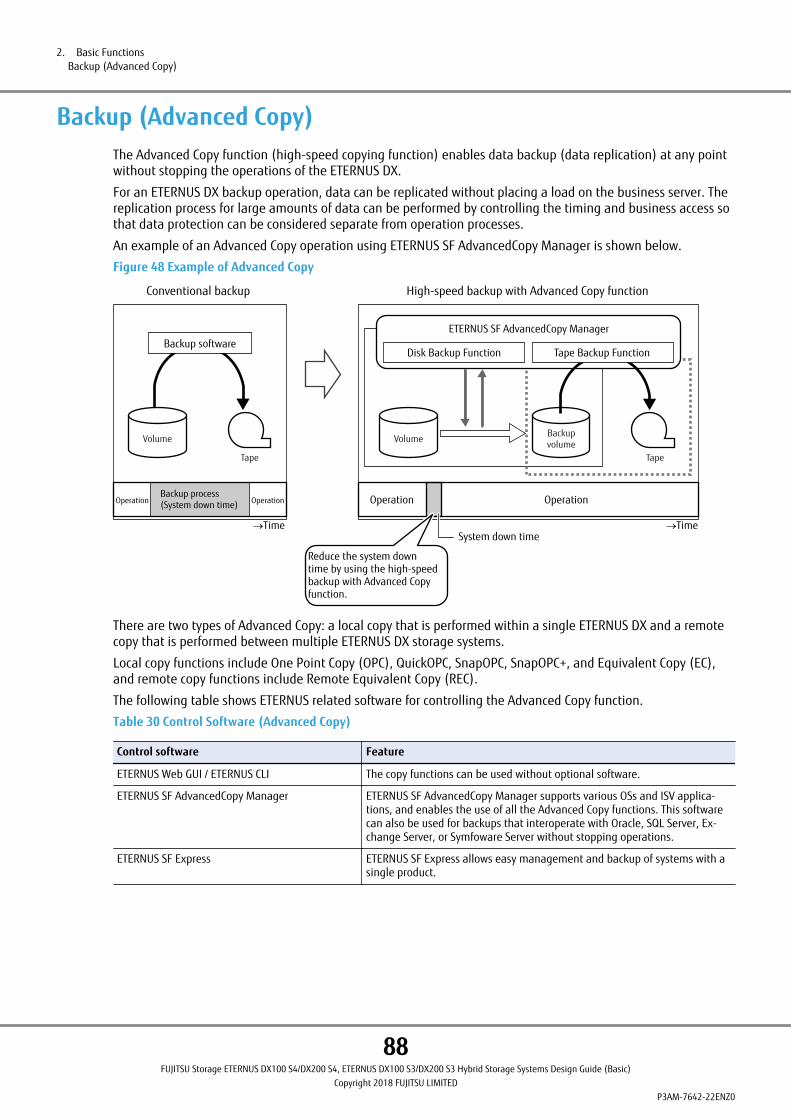
Backup (Advanced Copy)The Advanced Copy function (high-speed copying function) enables data backup (data replication) at any pointwithout stopping the operations of the ETERNUS DX.
For an ETERNUS DX backup operation, data can be replicated without placing a load on the business server. Thereplication process for large amounts of data can be performed by controlling the timing and business access sothat data protection can be considered separate from operation processes.
An example of an Advanced Copy operation using ETERNUS SF AdvancedCopy Manager is shown below.
Figure 48 Example of Advanced Copy
Volume Backupvolume
Tape
High-speed backup with Advanced Copy function
Time
OperationOperation
Time
OperationOperationBackup process(System down time)
System down time
Reduce the system downtime by using the high-speedbackup with Advanced Copyfunction.
Backup software
Volume
Tape
Conventional backup
ETERNUS SF AdvancedCopy Manager
Disk Backup Function Tape Backup Function
There are two types of Advanced Copy: a local copy that is performed within a single ETERNUS DX and a remotecopy that is performed between multiple ETERNUS DX storage systems.
Local copy functions include One Point Copy (OPC), QuickOPC, SnapOPC, SnapOPC+, and Equivalent Copy (EC),and remote copy functions include Remote Equivalent Copy (REC).
The following table shows ETERNUS related software for controlling the Advanced Copy function.
Table 30 Control Software (Advanced Copy)
Control software Feature
ETERNUS Web GUI / ETERNUS CLI The copy functions can be used without optional software.
ETERNUS SF AdvancedCopy Manager ETERNUS SF AdvancedCopy Manager supports various OSs and ISV applica-tions, and enables the use of all the Advanced Copy functions. This softwarecan also be used for backups that interoperate with Oracle, SQL Server, Ex-change Server, or Symfoware Server without stopping operations.
ETERNUS SF Express ETERNUS SF Express allows easy management and backup of systems with asingle product.
2. Basic FunctionsBackup (Advanced Copy)
88FUJITSU Storage ETERNUS DX100 S4/DX200 S4, ETERNUS DX100 S3/DX200 S3 Hybrid Storage Systems Design Guide (Basic)
Copyright 2018 FUJITSU LIMITEDP3AM-7642-22ENZ0

The following functions (copy methods) are available.
Table 31 List of Functions (Copy Methods)
Model Number of availablesessions
Control software
ETERNUS Web GUI /ETERNUS CLI
ETERNUS SF Advanced-Copy Manager ETERNUS SF Express
ETERNUS DX100 S4/DX100 S3
1,024 (*1)2,048 (*2)
SnapOPC+ SnapOPCSnapOPC+QuickOPCOPCECREC
SnapOPC+
ETERNUS DX200 S4/DX200 S3
2,048 (*1)4,096 (*2)
SnapOPC+ SnapOPCSnapOPC+QuickOPCOPCECREC
SnapOPC+
*1: The values if the controller firmware version is earlier than V10L60 or if the "Expand Volume Mode" is disa-bled.
*2: The values if the controller firmware version is V10L60 or later and if the "Expand Volume Mode" is ena-bled.
A copy is executed for each LUN. With ETERNUS SF AdvancedCopy Manager, a copy can also be executed for eachlogical disk (which is called a partition or a volume depending on the OS).
A copy cannot be executed if another function is running in the storage system or the target volume. For detailson the functions that can be executed simultaneously, refer to "Combinations of Functions That Are Available forSimultaneous Executions" (page 194).
Backup (SAN)
Local CopyThe Advanced Copy functions offer the following copy methods: "Mirror Suspend", "Background Copy", and "Copy-on-Write". The function names that are given to each method are as follows: "EC" for the "Mirror Suspend" meth-od, "OPC" for the "Background Copy" method, and "SnapOPC" for the "Copy-on-Write" method.
When a physical copy is performed for the same area after the initial copy, OPC offers "QuickOPC", which onlyperforms a physical copy of the data that has been updated from the previous version. The SnapOPC+ functiononly copies data that is to be updated and performs generation management of the copy source volume.
● OPC
All of the data in a volume at a specific point in time is copied to another volume in the ETERNUS DX.
OPC is suitable for the following usages:
• Performing a backup
• Performing system test data replication
• Restoring backup data (restoration after replacing a drive when the copy source drive has failed)
2. Basic FunctionsBackup (Advanced Copy)
89FUJITSU Storage ETERNUS DX100 S4/DX200 S4, ETERNUS DX100 S3/DX200 S3 Hybrid Storage Systems Design Guide (Basic)
Copyright 2018 FUJITSU LIMITEDP3AM-7642-22ENZ0

● QuickOPC
QuickOPC copies all data as initial copy in the same way as OPC. After all of the data is copied, only updated data(differential data) is copied. QuickOPC is suitable for the following usages:
• Creating a backup of the data that is updated in small amounts
• Performing system test data replication
• Restoration from a backup
● SnapOPC/SnapOPC+ (*1)
As updates occur in the source data, SnapOPC/SnapOPC+ saves the data prior to change to the copy destination(SDV/TPV/FTV). The data, prior to changes in the updated area, is saved to an SDP/TPP/FTRP. Create an SDPV forthe SDP when performing SnapOPC/SnapOPC+ by specifying an SDV as the copy destination.
SnapOPC/SnapOPC+ is suitable for the following usages:
• Performing temporary backup for tape backup
• Performing a backup of the data that is updated in small amounts (generation management is available forSnapOPC+)
*1: The difference between SnapOPC and SnapOPC+ is that SnapOPC+ manages the history of updated data asopposed to SnapOPC, which manages updated data for a single generation only. While SnapOPC managesupdated data in units per session thus saving the same data redundantly, SnapOPC+ has updated data ashistory information which can provide multiple backups for multiple generations.
● EC
An EC creates data that is mirrored from the copy source to the copy destination beforehand, and then suspendsthe copy and handles each data independently.
When copying is resumed, only updated data in the copy source is copied to the copy destination. If the copydestination data has been modified, the copy source data is copied again in order to maintain equivalence be-tween the copy source data and the copy destination data. EC is suitable for the following usages:
• Performing a backup
• Performing system test data replication
• Prepare an encrypted SDP when an encrypted SDV is used.
• If the SDP capacity is insufficient, a copy cannot be performed. In order to avoid this situation, an operationthat notifies the operation administrator of event information according to the remaining SDP capacity isrecommended. For more details on event notification, refer to "Event Notification" (page 82).
• For EC, the data in the copy destination cannot be referenced or updated until the copy session is suspen-ded. If the monitoring software (ServerView Agents) performs I/O access to the data in the copy destination,an I/O access error message is output to the server log message and other destinations. To prevent errormessages from being output, consider using other monitoring methods.
2. Basic FunctionsBackup (Advanced Copy)
90FUJITSU Storage ETERNUS DX100 S4/DX200 S4, ETERNUS DX100 S3/DX200 S3 Hybrid Storage Systems Design Guide (Basic)
Copyright 2018 FUJITSU LIMITEDP3AM-7642-22ENZ0
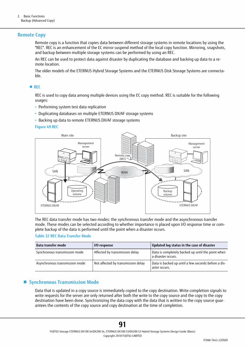
Remote CopyRemote copy is a function that copies data between different storage systems in remote locations by using the"REC". REC is an enhancement of the EC mirror suspend method of the local copy function. Mirroring, snapshots,and backup between multiple storage systems can be performed by using an REC.
An REC can be used to protect data against disaster by duplicating the database and backing up data to a re-mote location.
The older models of the ETERNUS Hybrid Storage Systems and the ETERNUS Disk Storage Systems are connecta-ble.
● REC
REC is used to copy data among multiple devices using the EC copy method. REC is suitable for the followingusages:
• Performing system test data replication
• Duplicating databases on multiple ETERNUS DX/AF storage systems
• Backing up data to remote ETERNUS DX/AF storage systems
Figure 49 REC
Backup site
Backup volume
SAN
Management server
Operating volume
SAN
Management server
Main site
WAN
ETERNUS DX/AF ETERNUS DX/AF
Remote copy(REC)
The REC data transfer mode has two modes: the synchronous transfer mode and the asynchronous transfermode. These modes can be selected according to whether importance is placed upon I/O response time or com-plete backup of the data is performed until the point when a disaster occurs.
Table 32 REC Data Transfer Mode
Data transfer mode I/O response Updated log status in the case of disaster
Synchronous transmission mode Affected by transmission delay Data is completely backed up until the point whena disaster occurs.
Asynchronous transmission mode Not affected by transmission delay Data is backed up until a few seconds before a dis-aster occurs.
■ Synchronous Transmission Mode
Data that is updated in a copy source is immediately copied to the copy destination. Write completion signals towrite requests for the server are only returned after both the write to the copy source and the copy to the copydestination have been done. Synchronizing the data copy with the data that is written to the copy source guar-antees the contents of the copy source and copy destination at the time of completion.
2. Basic FunctionsBackup (Advanced Copy)
91FUJITSU Storage ETERNUS DX100 S4/DX200 S4, ETERNUS DX100 S3/DX200 S3 Hybrid Storage Systems Design Guide (Basic)
Copyright 2018 FUJITSU LIMITEDP3AM-7642-22ENZ0
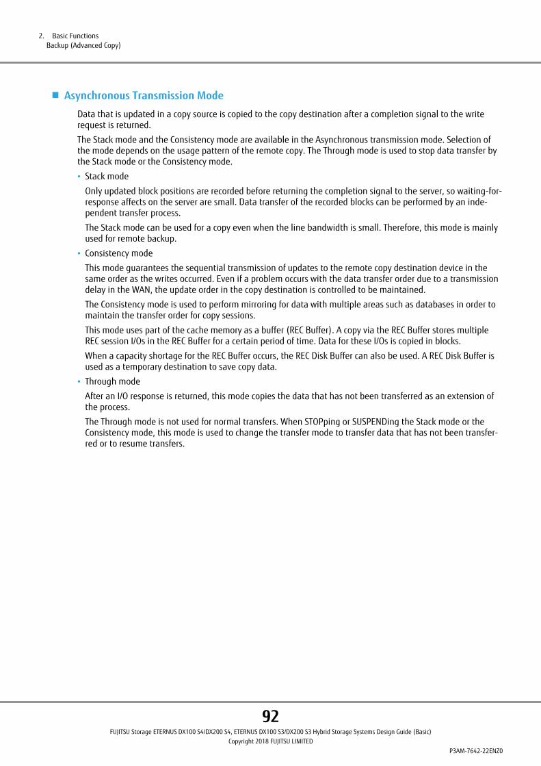
■ Asynchronous Transmission Mode
Data that is updated in a copy source is copied to the copy destination after a completion signal to the writerequest is returned.
The Stack mode and the Consistency mode are available in the Asynchronous transmission mode. Selection ofthe mode depends on the usage pattern of the remote copy. The Through mode is used to stop data transfer bythe Stack mode or the Consistency mode.
• Stack mode
Only updated block positions are recorded before returning the completion signal to the server, so waiting-for-response affects on the server are small. Data transfer of the recorded blocks can be performed by an inde-pendent transfer process.
The Stack mode can be used for a copy even when the line bandwidth is small. Therefore, this mode is mainlyused for remote backup.
• Consistency mode
This mode guarantees the sequential transmission of updates to the remote copy destination device in thesame order as the writes occurred. Even if a problem occurs with the data transfer order due to a transmissiondelay in the WAN, the update order in the copy destination is controlled to be maintained.
The Consistency mode is used to perform mirroring for data with multiple areas such as databases in order tomaintain the transfer order for copy sessions.
This mode uses part of the cache memory as a buffer (REC Buffer). A copy via the REC Buffer stores multipleREC session I/Os in the REC Buffer for a certain period of time. Data for these I/Os is copied in blocks.
When a capacity shortage for the REC Buffer occurs, the REC Disk Buffer can also be used. A REC Disk Buffer isused as a temporary destination to save copy data.
• Through mode
After an I/O response is returned, this mode copies the data that has not been transferred as an extension ofthe process.
The Through mode is not used for normal transfers. When STOPping or SUSPENDing the Stack mode or theConsistency mode, this mode is used to change the transfer mode to transfer data that has not been transfer-red or to resume transfers.
2. Basic FunctionsBackup (Advanced Copy)
92FUJITSU Storage ETERNUS DX100 S4/DX200 S4, ETERNUS DX100 S3/DX200 S3 Hybrid Storage Systems Design Guide (Basic)
Copyright 2018 FUJITSU LIMITEDP3AM-7642-22ENZ0
• When an REC is performed over a WAN, a bandwidth that supports the amount of updates from the servermust be secured. Regardless of the amount of updates from the server, a bandwidth of at least 50Mbit/s isrequired for the Synchronous mode and a bandwidth of at least 2Mbit/s for the Consistency mode (whendata is not being compressed by network devices).
• When an REC is performed over a WAN, the round-trip time for data transmissions must be 100ms or less. Asetup in which the round-trip time is 10ms or less is recommended for the synchronous transmission modebecause the effect upon the I/O response is significant.
• For REC, the data in the copy destination cannot be referenced or updated until the copy session is suspen-ded. If the monitoring software (ServerView Agents) performs I/O access to the data in the copy destination,an I/O access error message is output to the server log message and other destinations. To prevent errormessages from being output, consider using other monitoring methods.
• When a firmware update is performed, copy sessions must be suspended.
• The following models support REC Disk Buffers.
- ETERNUS DX100 S4/DX200 S4
- ETERNUS DX500 S4/DX600 S4
- ETERNUS DX100 S3/DX200 S3
- ETERNUS DX500 S3/DX600 S3
- ETERNUS DX8100 S3/DX8700 S3/DX8900 S3
- ETERNUS AF250 S2/AF650 S2
- ETERNUS AF250/AF650
- ETERNUS DX200F
- ETERNUS DX90 S2
- ETERNUS DX400/DX400 S2 series
- ETERNUS DX8000/DX8000 S2 series
• To use REC Disk Buffers, the controller firmware version of the ETERNUS DX must be V10L60-6000 or later,or V10L61-6000 or later.
• When the ETERNUS DX90, the ETERNUS DX400 series, or the ETERNUS DX8000 series is used as the copydestination, REC cannot be performed between encrypted volumes and unencrypted volumes.
2. Basic FunctionsBackup (Advanced Copy)
93FUJITSU Storage ETERNUS DX100 S4/DX200 S4, ETERNUS DX100 S3/DX200 S3 Hybrid Storage Systems Design Guide (Basic)
Copyright 2018 FUJITSU LIMITEDP3AM-7642-22ENZ0
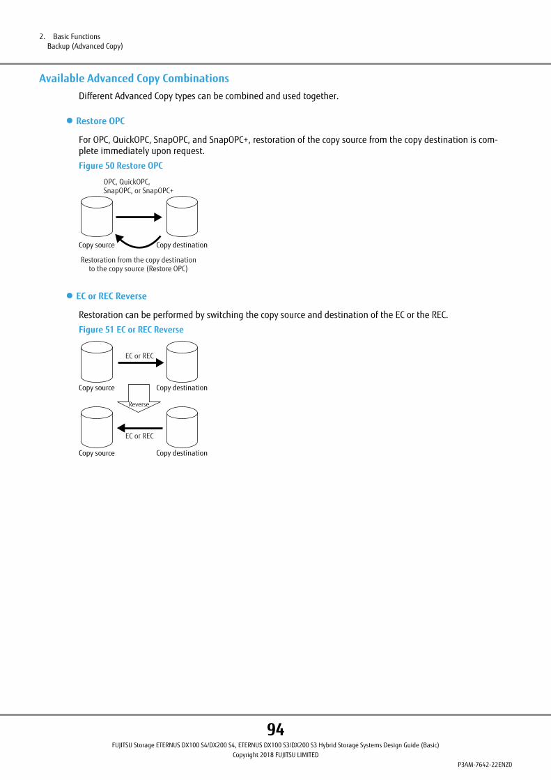
Available Advanced Copy CombinationsDifferent Advanced Copy types can be combined and used together.
● Restore OPC
For OPC, QuickOPC, SnapOPC, and SnapOPC+, restoration of the copy source from the copy destination is com-plete immediately upon request.
Figure 50 Restore OPC
Copy source Copy destination
OPC, QuickOPC,SnapOPC, or SnapOPC+
Restoration from the copy destinationto the copy source (Restore OPC)
● EC or REC Reverse
Restoration can be performed by switching the copy source and destination of the EC or the REC.
Figure 51 EC or REC Reverse
Copy source Copy destination
EC or REC
EC or REC
Copy source Copy destination
Reverse
2. Basic FunctionsBackup (Advanced Copy)
94FUJITSU Storage ETERNUS DX100 S4/DX200 S4, ETERNUS DX100 S3/DX200 S3 Hybrid Storage Systems Design Guide (Basic)
Copyright 2018 FUJITSU LIMITEDP3AM-7642-22ENZ0
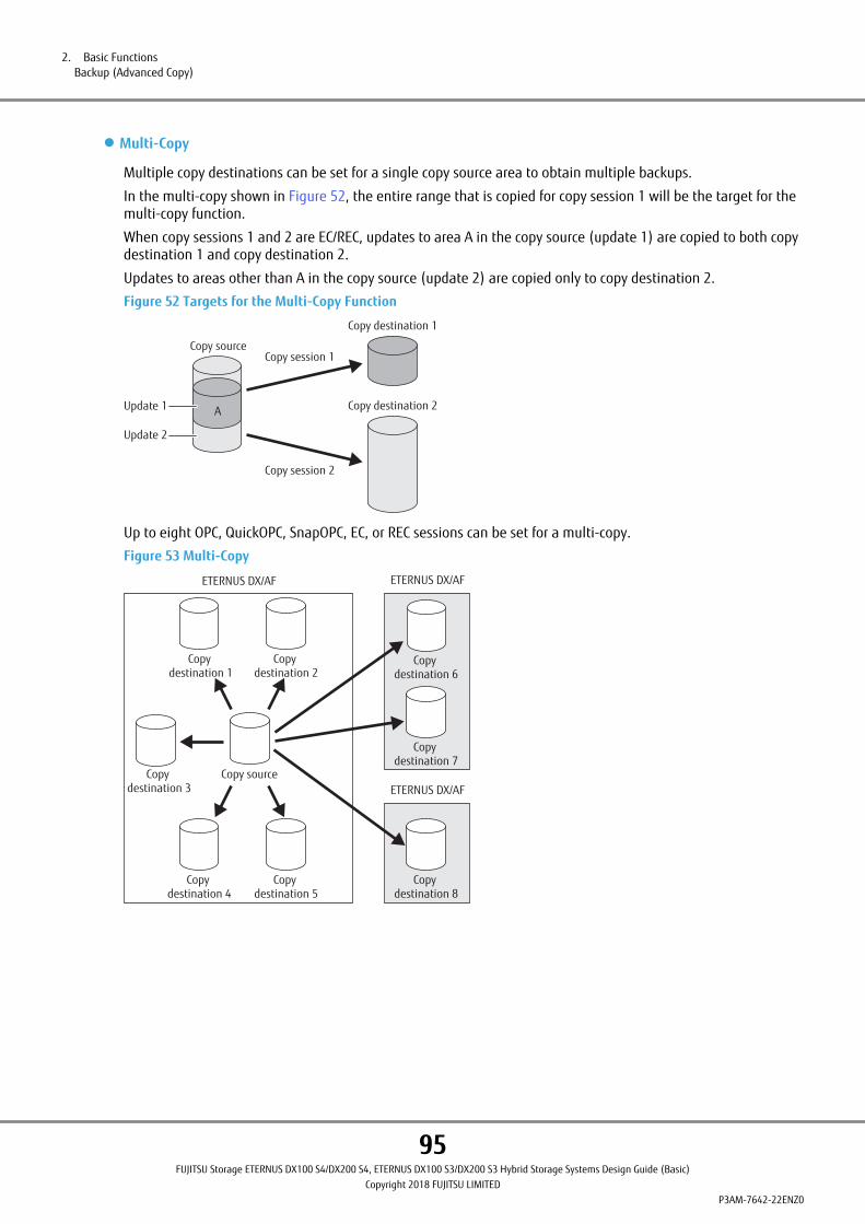
● Multi-Copy
Multiple copy destinations can be set for a single copy source area to obtain multiple backups.
In the multi-copy shown in Figure 52, the entire range that is copied for copy session 1 will be the target for themulti-copy function.
When copy sessions 1 and 2 are EC/REC, updates to area A in the copy source (update 1) are copied to both copydestination 1 and copy destination 2.
Updates to areas other than A in the copy source (update 2) are copied only to copy destination 2.
Figure 52 Targets for the Multi-Copy Function
Copy sourceCopy session 1
Copy session 2
Copy destination 1
Copy destination 2Update 1
Update 2
A
Up to eight OPC, QuickOPC, SnapOPC, EC, or REC sessions can be set for a multi-copy.
Figure 53 Multi-Copy
Copy destination 1
Copy source
Copy destination 2
Copy destination 3
Copy destination 4
Copy destination 5
Copy destination 6
Copy destination 7
Copy destination 8
ETERNUS DX/AFETERNUS DX/AF
ETERNUS DX/AF
2. Basic FunctionsBackup (Advanced Copy)
95FUJITSU Storage ETERNUS DX100 S4/DX200 S4, ETERNUS DX100 S3/DX200 S3 Hybrid Storage Systems Design Guide (Basic)
Copyright 2018 FUJITSU LIMITEDP3AM-7642-22ENZ0
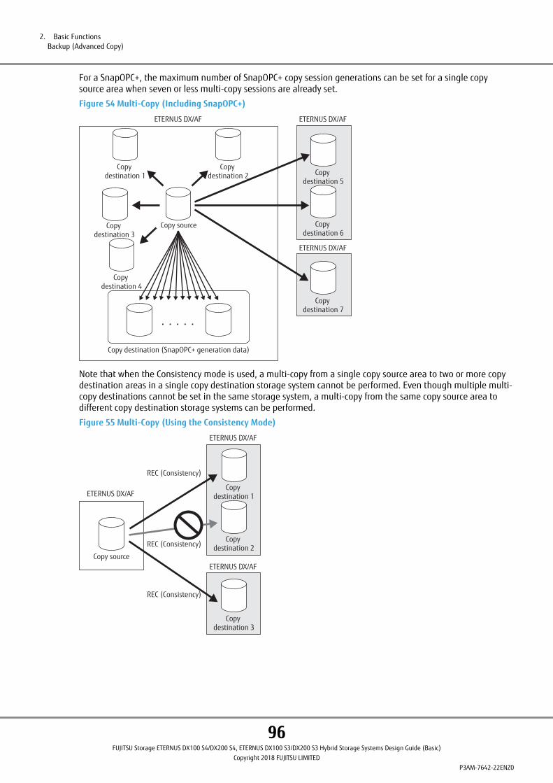
For a SnapOPC+, the maximum number of SnapOPC+ copy session generations can be set for a single copysource area when seven or less multi-copy sessions are already set.
Figure 54 Multi-Copy (Including SnapOPC+)
ETERNUS DX/AF
Copy destination 1
Copy destination 2
Copy destination 3
Copy destination 4
Copy destination 5
Copy destination 6
Copy destination 7
ETERNUS DX/AF
ETERNUS DX/AF
Copy source
Copy destination (SnapOPC+ generation data)
Note that when the Consistency mode is used, a multi-copy from a single copy source area to two or more copydestination areas in a single copy destination storage system cannot be performed. Even though multiple multi-copy destinations cannot be set in the same storage system, a multi-copy from the same copy source area todifferent copy destination storage systems can be performed.
Figure 55 Multi-Copy (Using the Consistency Mode)
Copy source
Copy destination 1
Copy destination 2
Copy destination 3
ETERNUS DX/AF
ETERNUS DX/AF
ETERNUS DX/AF
REC (Consistency)
REC (Consistency)
REC (Consistency)
2. Basic FunctionsBackup (Advanced Copy)
96FUJITSU Storage ETERNUS DX100 S4/DX200 S4, ETERNUS DX100 S3/DX200 S3 Hybrid Storage Systems Design Guide (Basic)
Copyright 2018 FUJITSU LIMITEDP3AM-7642-22ENZ0

When performing a Cascade Copy for an REC session in Consistency mode, the copy source of the session mustnot be related to another REC session in Consistency mode with the same destination storage system.
Figure 56 Multi-Copy (Case 1: When Performing a Cascade Copy for an REC Session in Consistency Mode)
Copydestination 1
Copydestination 2
Copydestination 3
ETERNUS DX/AF
Copy source
ETERNUS DX/AF
ETERNUS DX/AF
OPC / QuickOPC / EC
REC (Consistency)
REC (Consistency)
REC (Consistency)
Figure 57 Multi-Copy (Case 2: When Performing a Cascade Copy for an REC Session in Consistency Mode)
Copydestination 1
Copydestination 2
Copydestination 3
ETERNUS DX/AF
Copy source
ETERNUS DX/AF
ETERNUS DX/AF
OPC / QuickOPC / EC
REC (Consistency)
REC (Consistency)
REC (Consistency)
2. Basic FunctionsBackup (Advanced Copy)
97FUJITSU Storage ETERNUS DX100 S4/DX200 S4, ETERNUS DX100 S3/DX200 S3 Hybrid Storage Systems Design Guide (Basic)
Copyright 2018 FUJITSU LIMITEDP3AM-7642-22ENZ0
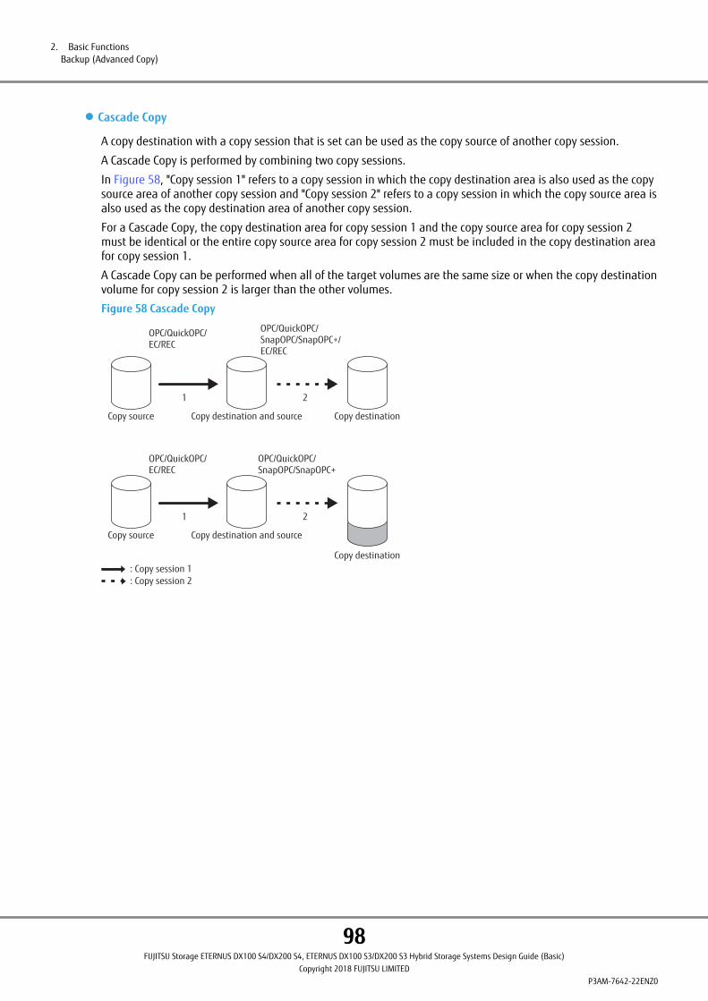
● Cascade Copy
A copy destination with a copy session that is set can be used as the copy source of another copy session.
A Cascade Copy is performed by combining two copy sessions.
In Figure 58, "Copy session 1" refers to a copy session in which the copy destination area is also used as the copysource area of another copy session and "Copy session 2" refers to a copy session in which the copy source area isalso used as the copy destination area of another copy session.
For a Cascade Copy, the copy destination area for copy session 1 and the copy source area for copy session 2must be identical or the entire copy source area for copy session 2 must be included in the copy destination areafor copy session 1.
A Cascade Copy can be performed when all of the target volumes are the same size or when the copy destinationvolume for copy session 2 is larger than the other volumes.
Figure 58 Cascade Copy
Copy source Copy destination and source
Copy destination
OPC/QuickOPC/EC/REC
OPC/QuickOPC/SnapOPC/SnapOPC+
: Copy session 1: Copy session 2
1 2
Copy source Copy destination and source Copy destination
OPC/QuickOPC/EC/REC
OPC/QuickOPC/SnapOPC/SnapOPC+/EC/REC
1 2
2. Basic FunctionsBackup (Advanced Copy)
98FUJITSU Storage ETERNUS DX100 S4/DX200 S4, ETERNUS DX100 S3/DX200 S3 Hybrid Storage Systems Design Guide (Basic)
Copyright 2018 FUJITSU LIMITEDP3AM-7642-22ENZ0

Table 33 shows the supported combinations when adding a copy session to a copy destination volume where acopy session has already been configured.
Table 33 Available Cascade Copy Combinations (When a Cascade Copy Performs Session 1 Followed by Session 2)
Copy session2
Copy session 1
OPC QuickOPC SnapOPC SnapOPC+ EC
REC syn-chronoustransmis-sion
REC Stackmode
REC Consisten-cy mode
OPC ¡ (*1) ¡ (*1) ´ ´ ¡ ¡ ¡ ¡
QuickOPC ¡ (*1) ¡ (*1) (*2) ´ ´ ¡ ¡ ¡ ¡
SnapOPC ¡ (*1) ¡ (*1) ´ ´ ¡ ¡ ¡ ¡
SnapOPC+ ¡ (*1) ¡ (*1) ´ ´ ¡ ¡ ¡ ¡
EC ¡ ¡ ´ ´ ¡ ¡ ¡ ¡
REC synchro-nous trans-mission
¡ (*3) ¡ (*3) ´ ´ ¡ (*3) ¡ (*3) ¡ (*3) ¡
(*3) (*4)
REC Stackmode
¡ ¡ ´ ´ ¡ ¡ ¡ ¡
REC Consis-tency mode
¡ (*3) ¡ (*3) ´ ´ ¡ (*3) ¡ ¡ (*3) ¡
(*3) (*4)
¡: Possible, ´: Not possible
*1: When copy session 2 is an OPC, QuickOPC, SnapOPC, or SnapOPC+ session, data in the copy destination ofcopy session 1 is backed up. Data is not backed up in the copy source of copy session 1.
*2: This combination is supported only if the copy size in both the copy source volume and the copy destina-tion volume is less than 2TB.
If the copy size is 2TB or larger, perform the following operations instead.
• When performing a temporary recovery
Use a Cascade Copy of QuickOPC (copy session 1) and OPC (copy session 2).
• When backing up two generations
Use a multi-copy that is configured with QuickOPC and QuickOPC.
*3: A Cascade Copy cannot be performed when a copy source and destination volume is in an older ETERNUSstorage system model.
*4: When copy session 1 uses the REC Consistency mode, the data transmission sequence of copy session 1 isguaranteed, but the data transmission sequence of copy session 2 is not guaranteed.
2. Basic FunctionsBackup (Advanced Copy)
99FUJITSU Storage ETERNUS DX100 S4/DX200 S4, ETERNUS DX100 S3/DX200 S3 Hybrid Storage Systems Design Guide (Basic)
Copyright 2018 FUJITSU LIMITEDP3AM-7642-22ENZ0

Table 34 shows the supported combinations when adding a copy session to a copy source volume where a copysession has already been configured.
Table 34 Available Cascade Copy Combinations (When a Cascade Copy Performs Session 2 Followed by Session 1)
Copy session1
Copy session 2
OPC QuickOPC SnapOPC SnapOPC+ EC
REC syn-chronoustransmis-sion
REC Stackmode
REC Consisten-cy mode
OPC ¡ ¡ ¡ ¡ ¡ ¡ ¡ ¡
QuickOPC ¡ ¡ (*1) ¡ ¡ ¡ ¡ ¡ ¡
SnapOPC ´ ´ ´ ´ ´ ´ ´ ´
SnapOPC+ ´ ´ ´ ´ ´ ´ ´ ´
EC ¡ ¡ ¡ ¡ ¡ ¡ ¡ ¡
REC synchro-nous trans-mission
¡ ¡ ¡ ¡ ¡ ¡ ¡ ¡
REC Stackmode
¡ ¡ ¡ ¡ ¡ ¡ ¡ ¡
REC Consis-tency mode
¡ ¡ ¡ ¡ ¡ ¡ (*2) ¡ ¡ (*2)
¡: Possible, ´: Not possible
*1: This combination is supported only if the copy size in both the copy source volume and the copy destina-tion volume is less than 2TB.
If the copy size is 2TB or larger, perform the following operations instead.
• When performing a temporary recovery
Use a Cascade Copy of QuickOPC (copy session 1) and OPC (copy session 2).
• When backing up two generations
Use a multi-copy that is configured with QuickOPC and QuickOPC.
*2: When copy session 1 uses the REC Consistency mode, the data transmission sequence of copy session 1 isguaranteed, but the data transmission sequence of copy session 2 is not guaranteed.
2. Basic FunctionsBackup (Advanced Copy)
100FUJITSU Storage ETERNUS DX100 S4/DX200 S4, ETERNUS DX100 S3/DX200 S3 Hybrid Storage Systems Design Guide (Basic)
Copyright 2018 FUJITSU LIMITEDP3AM-7642-22ENZ0

• To suspend a Cascade Copy where session 1 is performed before session 2 and session 2 is an EC or RECsession, perform the Suspend command after the physical copy for copy session 1 is complete.
• A Cascade Copy can be performed when the copy type for copy session 1 is XCOPY or ODX. The copy destina-tion area for XCOPY or ODX and the copy source area for copy session 2 do not have to be completely identi-cal. For example, a Cascade Copy can be performed when the copy source area for copy session 2 is onlypart of the copy destination area for copy session 1.
XCOPY or ODX cannot be set as the copy type for copy session 2 in a Cascade Copy.
• For more details on XCOPY and ODX, refer to "Server Linkage Functions" (page 125).
• To acquire valid backup data in the copy destination for copy session 2, a physical copy must be completedor suspended in all of the copy sessions that configure the Cascade Copy. Check the copy status for copysessions 1 and 2 when using the backup data.
However, if a Cascade Copy performs session 1 before session 2, and copy session 1 is an OPC or QuickOPCsession and copy session 2 is an OPC, QuickOPC, SnapOPC, or SnapOPC+ session, the data in the copy desti-nation for copy session 2 is available even during a physical copy.
• If copy session 1 is an EC or REC session and copy session 2 is an OPC, QuickOPC, SnapOPC, or SnapOPC+session, setting copy session 2 after setting copy session 1 to an equivalent or suspended state is recom-mended.
• When stopping an OPC or QuickOPC session for copy session 1 during a physical copy, stop copy session 2 inadvance if copy session 2 is an OPC, QuickOPC, SnapOPC, or SnapOPC+ session.
• If copy session 2 is an EC or REC session, copy session 2 does not transition to an equivalent state until thephysical copy for copy session 1 is complete. For an EC session, a copy session cannot be suspended untilthe session transitions to an equivalent state.
• If a Cascade Copy performs session 1 before session 2, and copy session 1 is an OPC or QuickOPC session, thelogical data in the intermediate volume when copy session 2 is started (the copy destination volume forcopy session 1) is copied to the copy destination volume for copy session 2. A logical data copy is shownbelow.
OPC / QuickOPC
OPC / QuickOPC / SnapOPC / SnapOPC+ / EC / REC
: Copy session 1: Copy session 2
2. Basic FunctionsBackup (Advanced Copy)
101FUJITSU Storage ETERNUS DX100 S4/DX200 S4, ETERNUS DX100 S3/DX200 S3 Hybrid Storage Systems Design Guide (Basic)
Copyright 2018 FUJITSU LIMITEDP3AM-7642-22ENZ0
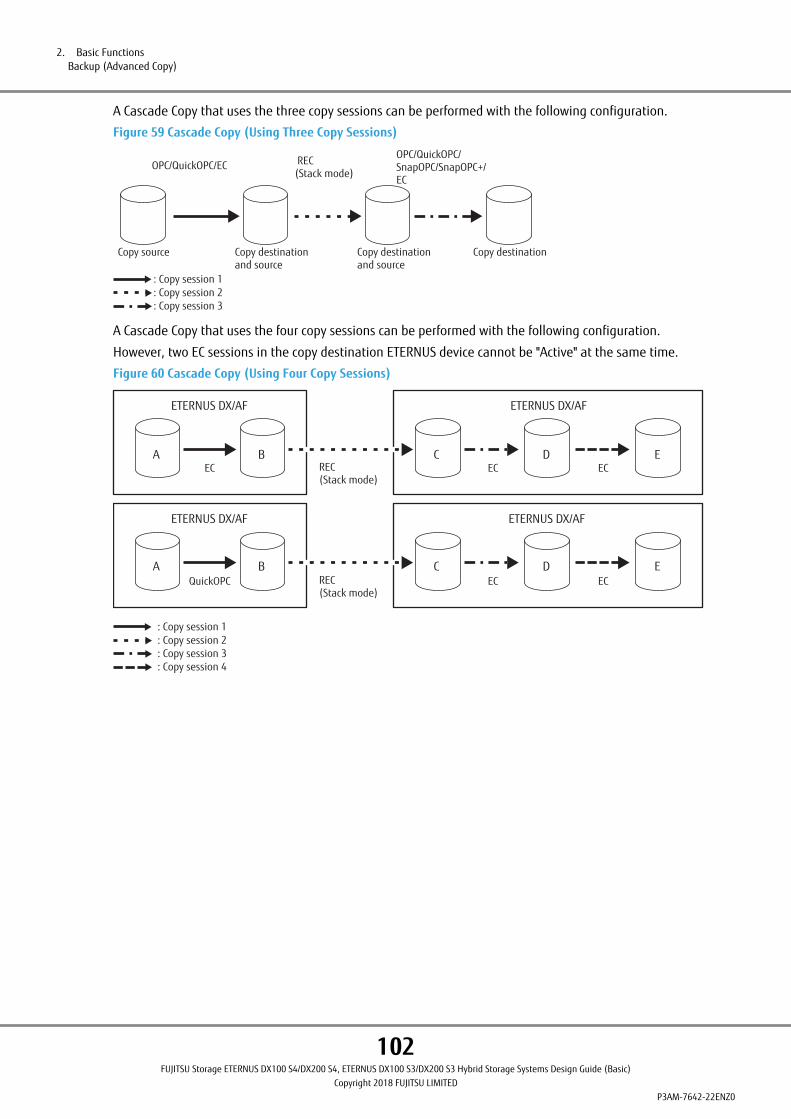
A Cascade Copy that uses the three copy sessions can be performed with the following configuration.
Figure 59 Cascade Copy (Using Three Copy Sessions)
Copy source Copy destination and source
Copy destination and source
OPC/QuickOPC/EC REC(Stack mode)
OPC/QuickOPC/SnapOPC/SnapOPC+/EC
Copy destination
: Copy session 1: Copy session 2: Copy session 3
A Cascade Copy that uses the four copy sessions can be performed with the following configuration.
However, two EC sessions in the copy destination ETERNUS device cannot be "Active" at the same time.
Figure 60 Cascade Copy (Using Four Copy Sessions)
REC(Stack mode)
: Copy session 1: Copy session 2: Copy session 3: Copy session 4
EC EC EC
REC(Stack mode)
QuickOPC EC EC
A B C D E
A B C D E
ETERNUS DX/AF ETERNUS DX/AF
ETERNUS DX/AF ETERNUS DX/AF
2. Basic FunctionsBackup (Advanced Copy)
102FUJITSU Storage ETERNUS DX100 S4/DX200 S4, ETERNUS DX100 S3/DX200 S3 Hybrid Storage Systems Design Guide (Basic)
Copyright 2018 FUJITSU LIMITEDP3AM-7642-22ENZ0

Performance Tuning
Striping Size ExpansionStriping Size Expansion is a function to expand the stripe depth value by specifying the stripe size when creatinga RAID group.
Expansion of the stripe size enables advanced performance tuning. For normal operations, the default valuedoes not need to be changed.
An expanded stripe depth reduces the number of drives that are accessed. A reduced number of commands todrives improves the access performance of the corresponding RAID1+0 RAID groups. However, it should be notedthat an expanded stripe depth may reduce the sequential write performance for RAID5.
The stripe depth values that are available for each RAID type are shown below.
Table 35 Available Stripe Depth
RAID type Drive configuration (*1) Available stripe depth
Mirroring (RAID1) 1D+1M —
High performance (RAID1+0) All drive configurations 64KB, 128KB, 256KB, 512KB, and 1,024KB
Striping (RAID0)
High capacity (RAID5) 2D+1P – 4D+1P 64KB, 128KB, 256KB, and 512KB
5D+1P – 8D+1P 64KB, 128KB, and 256KB
9D+1P – 15D+1P 64KB and 128KB
Reliability (RAID5+0) All drive configurations 64KB
High reliability (RAID6)
High reliability (RAID6-FR)
*1: D: Data, M: Mirror, P: Parity
• The read/write performance of the random access can be enhanced by changing the setting, however, notethat the performance can be degraded, depending on the used system.
• The following restrictions are applied to the RAID groups with expanded stripe sizes:
- Encryption and Logical Device Expansion cannot be performed on the volumes which belong to the RAIDgroup.
- RAID groups with different stripe sizes configured cannot coexist in the same TPP or FTSP pools.
- A WSV cannot be configured by concatenating RAID groups with different stripe sizes.
• "Stripe Depth 512KB" cannot be specified for a "RAID5 (4D+1P)" configuration that is used for TPPs andFTSPs.
• "Stripe Depth 256KB" cannot be specified for a "RAID5 (8D+1P)" configuration that is used for TPPs andFTSPs.
2. Basic FunctionsPerformance Tuning
103FUJITSU Storage ETERNUS DX100 S4/DX200 S4, ETERNUS DX100 S3/DX200 S3 Hybrid Storage Systems Design Guide (Basic)
Copyright 2018 FUJITSU LIMITEDP3AM-7642-22ENZ0

Assigned CMsA controller that controls access is assigned to each RAID group and manages the load balance in the ETERNUSDX. The controller that controls a RAID group is called an assigned CM.
Figure 61 Assigned CMs
ETERNUS DX
Switch
CM#1
RAID group #1RAID group #0
Switch
RAID group #2
CM#0
AssignedCM
The assigned CM of the RAID group controls access
AssignedCM
When the load is unbalanced between the controllers, change the assigned CM.
If an assigned controller is disconnected for any reason, the assigned CM is replaced by another controller. Afterthe disconnected controller is installed again and returns to normal status, this controller becomes the assignedCM again.
2. Basic FunctionsPerformance Tuning
104FUJITSU Storage ETERNUS DX100 S4/DX200 S4, ETERNUS DX100 S3/DX200 S3 Hybrid Storage Systems Design Guide (Basic)
Copyright 2018 FUJITSU LIMITEDP3AM-7642-22ENZ0

3. SAN Functions
This chapter describes the functions that are available when a SAN connection is used.
Operations Optimization (Deduplication/Compression)
• A single controller configuration differs from a dual controller configuration in the following ways:
- The Deduplication/Compression function cannot be used.
• The Deduplication/Compression function cannot be used if the Unified kit/Unified License is installed.
Deduplication/CompressionThe Deduplication/Compression function analyzes duplicated data in every 4KB of the write data from the server,and writes the duplicated data only once. After the first write, the data is referenced instead of writing the samedata again. This reduces the total write size. Also, with the Compression function further data reduction is realiz-ed.
The Deduplication/Compression function can be used for the ETERNUS DX200 S4/DX200 S3.
The Deduplication/Compression function can not only perform both deduplication and compression at the sametime, but can also perform only deduplication or compression individually.
Overviews of the Deduplication/Compression function, the Deduplication function, and the Compression functionare described below.
105FUJITSU Storage ETERNUS DX100 S4/DX200 S4, ETERNUS DX100 S3/DX200 S3 Hybrid Storage Systems Design Guide (Basic)
Copyright 2018 FUJITSU LIMITEDP3AM-7642-22ENZ0
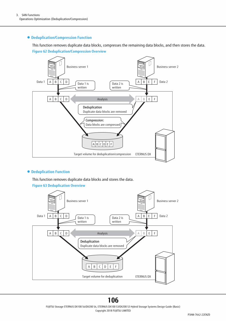
● Deduplication/Compression Function
This function removes duplicate data blocks, compresses the remaining data blocks, and then stores the data.
Figure 62 Deduplication/Compression Overview
A B C D E F
Business server 2
Target volume for deduplication/compression
AnalysisA B C D
A B C DData 1
Business server 1
Data 2A B E F
A B E F
Data 1 is written
Data 2 is written
DeduplicationDeduplicationDuplicate data blocks are removed
Compression:Compression:Data blocks are compressed
ETERNUS DX
● Deduplication Function
This function removes duplicate data blocks and stores the data.
Figure 63 Deduplication Overview
A B C D E F
Business server 2
Target volume for deduplication
Analysis
A B C DData 1
Business server 1
Data 2A B E FData 1 is written
Data 2 is written
DeduplicationDeduplicationDuplicate data blocks are removed
ETERNUS DX
A B C D A B E F
3. SAN FunctionsOperations Optimization (Deduplication/Compression)
106FUJITSU Storage ETERNUS DX100 S4/DX200 S4, ETERNUS DX100 S3/DX200 S3 Hybrid Storage Systems Design Guide (Basic)
Copyright 2018 FUJITSU LIMITEDP3AM-7642-22ENZ0
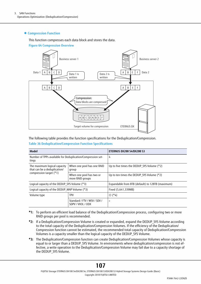
● Compression Function
This function compresses each data block and stores the data.
Figure 64 Compression Overview
A B C D A B E F
Business server 2
Target volume for compression
A B C DData 1
Business server 1
Data 2A B E FData 1 is written
Data 2 is written
Compression:Compression:Data blocks are compressed
ETERNUS DX
A B E FA B C D
The following table provides the function specifications for the Deduplication/Compression.
Table 36 Deduplication/Compression Function Specifications
Model ETERNUS DX200 S4/DX200 S3
Number of TPPs available for Deduplication/Compression set-tings
4
The maximum logical capacitythat can be a deduplication/compression target (*1)
When one pool has one RAIDgroup
Up to five times the DEDUP_SYS Volume (*2)
When one pool has two ormore RAID groups
Up to ten times the DEDUP_SYS Volume (*2)
Logical capacity of the DEDUP_SYS Volume (*3) Expandable from 8TB (default) to 128TB (maximum)
Logical capacity of the DEDUP_MAP Volume (*3) Fixed (5,641,339MB)
Volume type TPV ¡ (*4)
Standard / FTV / WSV / SDV /SDPV / VVOL / ODX
´
*1: To perform an efficient load balance of the Deduplication/Compression process, configuring two or moreRAID groups per pool is recommended.
*2: If a Deduplication/Compression Volume is created or expanded, expand the DEDUP_SYS Volume accordingto the total capacity of the Deduplication/Compression Volumes. If the efficiency of the Deduplication/Compression function cannot be estimated, the recommended total capacity of Deduplication/CompressionVolumes is a capacity smaller than the logical capacity of the DEDUP_SYS Volume.
*3: The Deduplication/Compression function can create Deduplication/Compression Volumes whose capacity isequal to or larger than a DEDUP_SYS Volume. In environments where deduplication/compression is not ef-fective, a write operation to the Deduplication/Compression Volume may fail due to a capacity shortage ofthe DEDUP_SYS Volume.
3. SAN FunctionsOperations Optimization (Deduplication/Compression)
107FUJITSU Storage ETERNUS DX100 S4/DX200 S4, ETERNUS DX100 S3/DX200 S3 Hybrid Storage Systems Design Guide (Basic)
Copyright 2018 FUJITSU LIMITEDP3AM-7642-22ENZ0

In addition, if the DEDUP_SYS Volume capacity runs out or is close to running out, an SNMP Trap is sent.
*4: NAS user volumes are not supported.
The Memory Extension must be installed to use the Deduplication/Compression function. The Memory Extensionis installed as standard in the controller module for standard models of the ETERNUS DX200 S4.
● Performance When Using the Deduplication/Compression Function
The ETERNUS DX performs data deduplication/compression in synchronization with the I/O from the server.
• Using this function in environments where random access occurs is recommended. Data is intermittently stor-ed in Deduplication/Compression Volumes because data is appended.
• I/O response may significantly degrade when compared to systems that do not use the Deduplication/Compression function.
• Using this function in environments where the I/O size is 32KB or smaller is recommended. The performance isaffected in environments where the I/O size is large because data is deduplicated and compressed every 4KB.
• If the I/O size or the boundaries of the I/O address are not 4KB, the performance is affected because the partsless than 4KB are read in the ETERNUS DX.
• If I/Os are issued to the Deduplication/Compression Volumes, the CPU usage rate increases. The performanceof non-Deduplication/Compression Volumes may also be affected.
• The performance may decline when the Deduplication/Compression function is enabled. Using the Dedupli-cation/Compression function is not recommended for the volumes that are used to store performance-sensi-tive data.
• Batch process (or sequential access) performance significantly degrades because data is written to drivesintermittently or a large amount of references and updates occur. In environments where sequential accessoccurs, using the Deduplication/Compression function is not recommended.
• The Deduplication/Compression function becomes a disadvantage in terms of performance and capacity if avolume stores data such as videos to which deduplication/compression is not effective and the volume is setas a Deduplication/Compression Volume. Only enable either the Deduplication function or the Compressionfunction.
● Configuration Method
• Enabling the Deduplication/Compression function
From ETERNUS Web GUI or ETERNUS CLI, enable the Deduplication/Compression function for the TPP. Not onlycan the Deduplication/Compression function be enabled, but the Deduplication function or the Compressionfunction can be individually enabled.
The Deduplication/Compression function can be enabled by performing one of the methods below.
Table 37 Method for Enabling the Deduplication/Compression Function
Condition of the TPP Chunk size (*1) Creation method
A newly created TPP 21MB Select AUTO mode and specify an optionfor the Deduplication/Compression func-tion to enable the function (*2)
A TPP that is created with a controllerfirmware version earlier than V10L70
21MB Select a target TPP to enable the Dedu-plication/Compression function (*3)
A TPP that is created with a controllerfirmware version V10L70 and later (theDedup Ready setting is specified whenthe TPP is created)
21MB Select a target TPP to enable the Dedu-plication/Compression function (*3) (*4)
3. SAN FunctionsOperations Optimization (Deduplication/Compression)
108FUJITSU Storage ETERNUS DX100 S4/DX200 S4, ETERNUS DX100 S3/DX200 S3 Hybrid Storage Systems Design Guide (Basic)
Copyright 2018 FUJITSU LIMITEDP3AM-7642-22ENZ0

Condition of the TPP Chunk size (*1) Creation method
A TPP that is created with a controllerfirmware version V10L70 and later (theDedup Ready setting is not specifiedwhen the TPP is created)
21MB Select a target TPP to enable the Dedu-plication/Compression function (*3) (*4)
Other than 21MB Deduplication/Compression function can-not be enabled (*5)
*1: The chunk size can be checked in the detail display of the TPP.
*2: This setting is available only if the TPP is created with the AUTO mode. In consideration of the load bal-ancing for the Deduplication/Compression process, using this creation method is recommended. If theTPP can only be configured with one RAID group, the Deduplication/Compression function cannot be ena-bled.
*3: The Deduplication/Compression function can be enabled even if the TPP is configured with only one RAIDgroup. However, if the TPP is configured with one RAID group, the load of the Deduplication/Compressionprocesses cannot be balanced efficiently. Enabling the Deduplication/Compression function for a TPP thatis configured with two or more RAID groups is recommended.
*4: To create a TPP with a chunk size of 21MB, specify the Dedup Ready option when creating the TPP.
*5: This function cannot be performed if the chunk size of the TPP is not 21MB.
• Configuration method for the Deduplication/Compression function
Select the TPP where the Deduplication/Compression function is enabled, and create Deduplication/Compres-sion Volumes (TPVs) in the selected TPP.
If I/O load exists in the ETERNUS DX, enabling or disabling the Deduplication/Compression function in the TPPmay take time. If I/O load exists, changing the setting of the Deduplication/Compression function for each TPPis recommended.
Specify whether to enable or disable the Deduplication/Compression function for each TPV. TPVs (or Deduplica-tion/Compression Volumes) where the Deduplication/Compression function is enabled and disabled can existtogether within the same TPP. However, these two types of TPVs should be located in separate TPPs.
Deduplication is performed for Deduplication/Compression Volumes within the same TPP. Deduplication is notperformed for data in different TPPs. In some cases, deduplication might not be performed even within thesame TPP.
To enable the Deduplication/Compression function for existing volumes, use the RAID Migration function.
Volumes that are to be created and the Deduplication/Compression setting for TPPs where the target volumescan be created vary depending on the selection of "Deduplication" and "Compression".
• Volumes that are to be created
Table 38 Volumes That Are to Be Created depending on the Selection of "Deduplication" and "Compression"
ConditionVolumes that are to be created
Deduplication Compression
Enable Enable Deduplication/Compression Volumes where both Deduplica-tion and Compression are enabled
Enable Disable Deduplication/Compression Volumes where only Deduplicationis enabled
Disable Enable Deduplication/Compression Volumes where only Compressionis enabled
Disable Disable TPVs for SAN where both Deduplication and Compression aredisabled
3. SAN FunctionsOperations Optimization (Deduplication/Compression)
109FUJITSU Storage ETERNUS DX100 S4/DX200 S4, ETERNUS DX100 S3/DX200 S3 Hybrid Storage Systems Design Guide (Basic)
Copyright 2018 FUJITSU LIMITEDP3AM-7642-22ENZ0
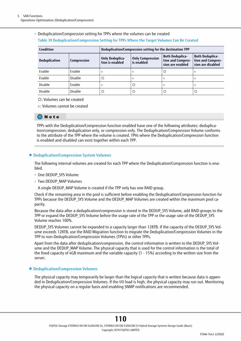
• Deduplication/Compression setting for TPPs where the volumes can be created
Table 39 Deduplication/Compression Setting for TPPs Where the Target Volumes Can Be Created
Condition Deduplication/Compression setting for the destination TPP
Deduplication Compression Only Deduplica-tion is enabled
Only Compressionis enabled
Both Deduplica-tion and Compres-sion are enabled
Both Deduplica-tion and Compres-sion are disabled
Enable Enable ´ ´ ¡ ´
Enable Disable ¡ ´ ´ ´
Disable Enable ´ ¡ ´ ´
Disable Disable ¡ ¡ ¡ ¡
¡: Volumes can be created
´: Volumes cannot be created
TPPs with the Deduplication/Compression function enabled have one of the following attributes: deduplica-tion/compression, deduplication only, or compression only. The Deduplication/Compression Volume conformsto the attribute of the TPP where the volume is created. TPVs where the Deduplication/Compression functionis enabled and disabled can exist together within each TPP.
● Deduplication/Compression System Volumes
The following internal volumes are created for each TPP where the Deduplication/Compression function is ena-bled.
• One DEDUP_SYS Volume
• Two DEDUP_MAP Volumes
A single DEDUP_MAP Volume is created if the TPP only has one RAID group.
Check if the remaining area in the pool is sufficient before enabling the Deduplication/Compression function forTPPs because the DEDUP_SYS Volume and the DEDUP_MAP Volumes are created within the maximum pool ca-pacity.
Because the data after a deduplication/compression is stored in the DEDUP_SYS Volume, add RAID groups to theTPP or expand the DEDUP_SYS Volume before the usage rate of the TPP or the usage rate of the DEDUP_SYSVolume reaches 100%.
DEDUP_SYS Volumes cannot be expanded to a capacity larger than 128TB. If the capacity of the DEDUP_SYS Vol-ume exceeds 128TB, use the RAID Migration function to migrate the Deduplication/Compression Volumes in theTPP to non-Deduplication/Compression Volumes (TPVs) or other TPPs.
Apart from the data after deduplication/compression, the control information is written to the DEDUP_SYS Vol-ume and the DEDUP_MAP Volume. The physical capacity that is used for the control information is the total ofthe fixed capacity of 4GB maximum and the variable capacity (1 - 15%) according to the written size from theserver.
● Deduplication/Compression Volumes
The physical capacity may temporarily be larger than the logical capacity that is written because data is appen-ded in Deduplication/Compression Volumes. If the I/O load is high, the physical capacity may run out. Monitoringthe physical capacity on a regular basis and enabling SNMP notifications are recommended.
3. SAN FunctionsOperations Optimization (Deduplication/Compression)
110FUJITSU Storage ETERNUS DX100 S4/DX200 S4, ETERNUS DX100 S3/DX200 S3 Hybrid Storage Systems Design Guide (Basic)
Copyright 2018 FUJITSU LIMITEDP3AM-7642-22ENZ0
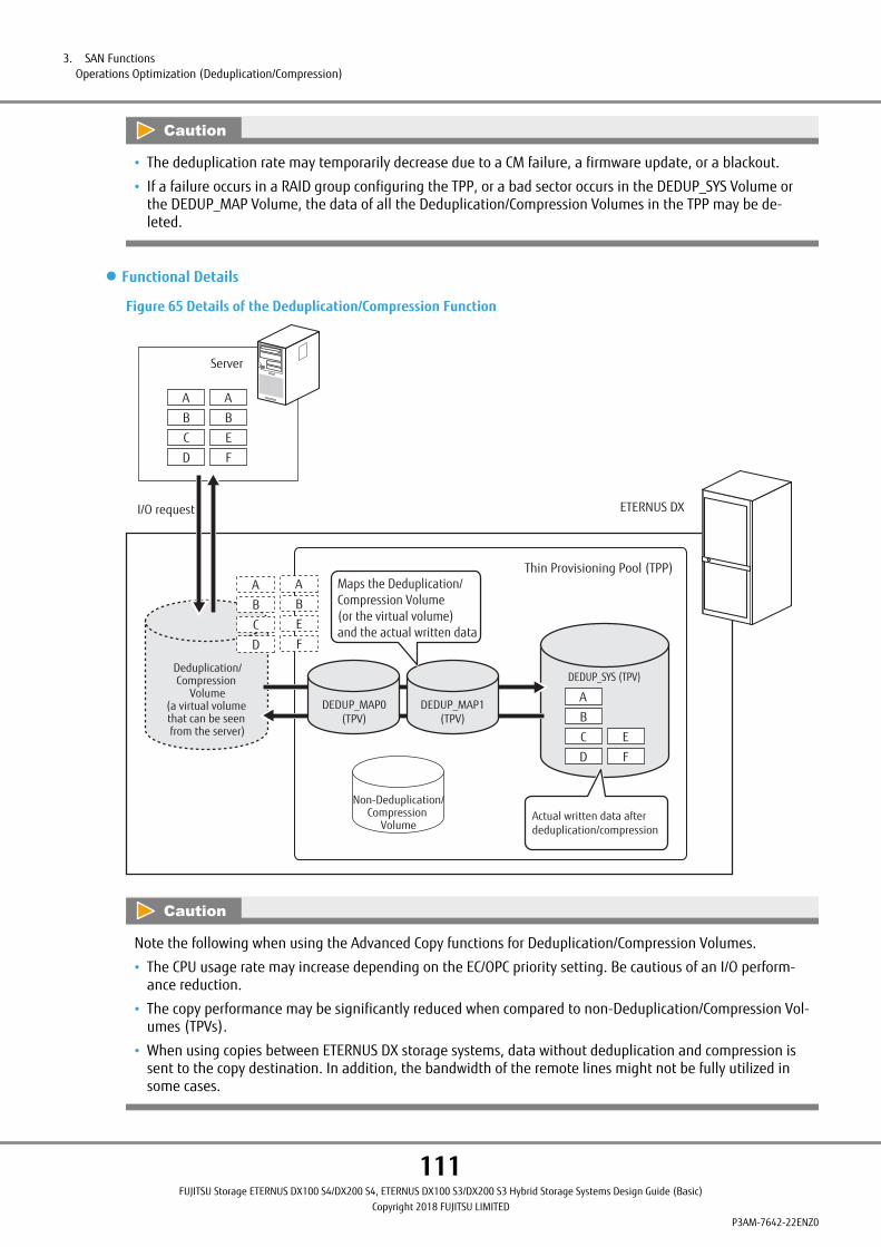
• The deduplication rate may temporarily decrease due to a CM failure, a firmware update, or a blackout.
• If a failure occurs in a RAID group configuring the TPP, or a bad sector occurs in the DEDUP_SYS Volume orthe DEDUP_MAP Volume, the data of all the Deduplication/Compression Volumes in the TPP may be de-leted.
● Functional Details
Figure 65 Details of the Deduplication/Compression Function
Deduplication/Compression
Volume(a virtual volume that can be seen from the server)
ETERNUS DX
Server
I/O request
Thin Provisioning Pool (TPP)
D
C
B
A
DEDUP_MAP0(TPV)
Non-Deduplication/Compression
Volume
DEDUP_MAP1(TPV)
Actual written data after deduplication/compression
DEDUP_SYS (TPV)
Maps the Deduplication/Compression Volume (or the virtual volume) and the actual written data
D
C
B
A
F
E
B
A
F
E
B
A
D
C
B
A
F
E
Note the following when using the Advanced Copy functions for Deduplication/Compression Volumes.
• The CPU usage rate may increase depending on the EC/OPC priority setting. Be cautious of an I/O perform-ance reduction.
• The copy performance may be significantly reduced when compared to non-Deduplication/Compression Vol-umes (TPVs).
• When using copies between ETERNUS DX storage systems, data without deduplication and compression issent to the copy destination. In addition, the bandwidth of the remote lines might not be fully utilized insome cases.
3. SAN FunctionsOperations Optimization (Deduplication/Compression)
111FUJITSU Storage ETERNUS DX100 S4/DX200 S4, ETERNUS DX100 S3/DX200 S3 Hybrid Storage Systems Design Guide (Basic)
Copyright 2018 FUJITSU LIMITEDP3AM-7642-22ENZ0

● Operation of the Deduplication/Compression Volumes
The following table provides management functions for volumes related to Deduplication/Compression.
Table 40 Target Deduplication/Compression Volumes of Each Function
Action Deduplication/CompressionVolumes DEDUP_SYS Volumes DEDUP_MAP Volumes
Creation ¡ ´ (*1) ´ (*1)
Deletion ¡ ´ (*2) ´ (*2)
Rename ¡ ´ ´
Format ¡ ¡ ´ (*3)
Eco-mode ´ ´ ´
TPV capacity expansion ¡ ¡ ´
RAID Migration ¡ ´ ´
Balancing ´ ´ ´
TPV/FTV capacity optimization ´ ¡ ¡
Modify threshold ´ ´ ´
Encrypt volume (*4) ¡ ´ (*1) ´ (*1)
Decrypt volume (*5) ¡ ´ ´
Advanced Copy function(Local copy)
¡ ´ ´
Advanced Copy function(Remote Copy)
¡ ´ ´
Forbid Advanced Copy ¡ ´ ´
Release reservation ¡ ´ ´
Performance monitoring ¡ ´ ´
Modify cache parameters ´ ¡ ¡
Create a LUN while rebuilding ¡ ´ (*1) ´ (*1)
LUN mapping ¡ ´ ´
QoS ¡ ´ ´
Create ODX Buffer volume ´ ´ ´
Storage Migration ¡ ´ ´
Non-disruptive Storage Migra-tion
¡ ´ ´
Storage Cluster ¡ ´ ´
Extreme Cache Pool ´ ¡ ¡
*1: Automatically created when the Deduplication/Compression function is enabled for TPPs.
*2: Automatically deleted when the Deduplication/Compression function is disabled for TPPs.
*3: When DEDUP_SYS Volumes are formatted, DEDUP_MAP Volumes are also formatted.
*4: Encryption can be performed by creating a volume in the encrypted pool, or migrating a volume to an en-crypted pool.
*5: Decryption of volumes is performed by specifying "Unencrypted" for the migration destination when mi-grating the volumes.
3. SAN FunctionsOperations Optimization (Deduplication/Compression)
112FUJITSU Storage ETERNUS DX100 S4/DX200 S4, ETERNUS DX100 S3/DX200 S3 Hybrid Storage Systems Design Guide (Basic)
Copyright 2018 FUJITSU LIMITEDP3AM-7642-22ENZ0
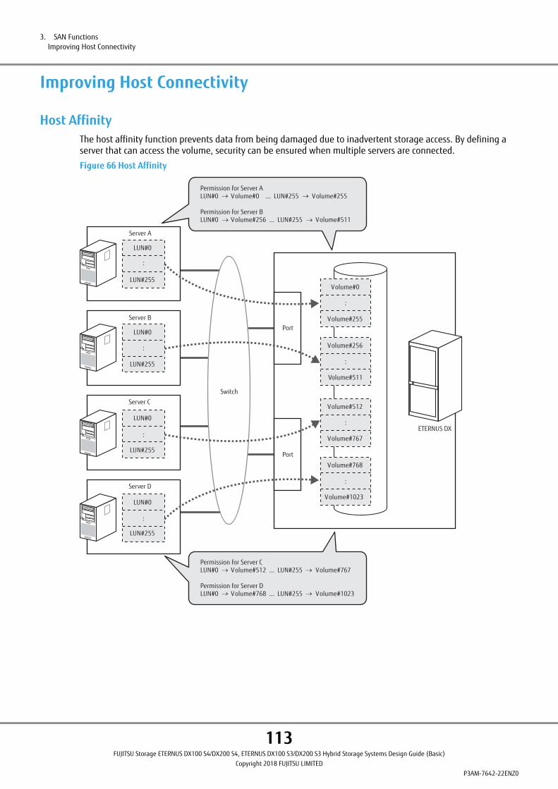
Improving Host Connectivity
Host AffinityThe host affinity function prevents data from being damaged due to inadvertent storage access. By defining aserver that can access the volume, security can be ensured when multiple servers are connected.
Figure 66 Host Affinity
Permission for Server ALUN#0 Volume#0 ... LUN#255 Volume#255
Permission for Server BLUN#0 Volume#256 ... LUN#255 Volume#511
Permission for Server CLUN#0 Volume#512 ... LUN#255 Volume#767
Permission for Server DLUN#0 Volume#768 ... LUN#255 Volume#1023
Switch
Server A
LUN#0
:
LUN#255
Server B
LUN#0
LUN#255
Server D
LUN#0
:
LUN#255
Server C
LUN#0
:
LUN#255
Volume#0
:
Volume#255
Volume#256
:
Volume#511
Volume#512
:
Volume#767
Volume#768
Volume#1023
:
Port
Port
:
ETERNUS DX
3. SAN FunctionsImproving Host Connectivity
113FUJITSU Storage ETERNUS DX100 S4/DX200 S4, ETERNUS DX100 S3/DX200 S3 Hybrid Storage Systems Design Guide (Basic)
Copyright 2018 FUJITSU LIMITEDP3AM-7642-22ENZ0

The host affinity can be set by associating "Host Groups", "CA Port Groups", and "LUN Groups".
Figure 67 Associating Host Groups, CA Port Groups, and LUN Groups
Server A
Server B
Server C
Server D
Switch
Switch
Switch
Switch
ETERNUS DXHost group 1
LUN group 1
Host group 2
CA port group 1
CA port group 2
LUN group 2
HBA
HBA
HBA
HBA
HBA
HBA
HBA
HBA
Port
Port
Port
Port
Vol#0 Vol#1 Vol#2
Vol#10 Vol#11
The host affinity can also be set by directly specifying the host and the CA port without creating host groups andCA port groups.
● Host Group
A host group is a group of hosts that have the same host interface type and that access the same LUN group.HBAs in multiple hosts can be configured in a single host group.
● CA Port Group
A CA port group is a group of the same CA type ports that are connected to a specific host group. A CA port groupis configured with ports that access the same LUN group, such as ports that are used for multipath connection tothe server or for connecting to the cluster configuring server. A single CA port group can be connected to multi-ple host groups.
● LUN Group
A LUN group is a group of LUNs that can be recognized by the host and the LUN group can be accessed from thesame host group and CA port groups.
A LUN group is mapping information for LUNs and volumes.
• Host access must be prevented when changing or deleting already set host affinity settings. When adding anew LUN to the host affinity settings, it is not necessary to stop host access.
• When servers are duplicated and connected using a cluster configuration to share a single ETERNUS DXamong multiple servers, cluster control software is required.
3. SAN FunctionsImproving Host Connectivity
114FUJITSU Storage ETERNUS DX100 S4/DX200 S4, ETERNUS DX100 S3/DX200 S3 Hybrid Storage Systems Design Guide (Basic)
Copyright 2018 FUJITSU LIMITEDP3AM-7642-22ENZ0

iSCSI SecurityFor an iSCSI interface, the iSCSI authentication function can be used when the initiator accesses the target. TheiSCSI authentication function is available for host connections and remote copying.
The Challenge Handshake Authentication Protocol (CHAP) is supported for iSCSI authentication. For CHAP Au-thentication, unidirectional CHAP or bidirectional CHAP can be selected. When unidirectional CHAP is used, thetarget authenticates the initiator to prevent fraudulent access. When bidirectional CHAP is used, the target au-thenticates the initiator to prevent fraudulent access and the initiator authenticates the target to prevent imper-sonation.
Note that the Internet Storage Name Service (iSNS) is also supported as an iSCSI name resolution.
Stable Operation via Load Control
Quality of Service (QoS)
● QoS
The performance of a high priority server is guaranteed by configuring the performance limit of each connectedserver.
When the load from one application is high in a storage integrated environment and sufficient resources toprocess other operations cannot be secured, performance may be reduced.
The QoS function guarantees performance by limiting resources for applications with a low priority so that re-sources are secured for high priority applications.
16 priority levels of bandwidth limits (maximum performance limits) can be configured on the hosts, CA ports,volumes, and LUN groups.
In addition, scheduled operations (when setting a bandwidth limit for hosts, CA ports, and LUN groups) are pos-sible by setting a duration using ETERNUS CLI.
Linking with ETERNUS SF Storage Cruiser significantly reduces the operation workload on the system administra-tor when applying the QoS function because performance designing and tuning are automatically performed.
Figure 68 QoS
ETERNUS DX
Server BHigh priority
Server ALow priority
Affects the performance of B
I/O performanceHigh
I/O performanceHigh
Server A
Server B
Processing requests from A increase
Required performance for A
Required performance for B
Server A
Server B
The workload does not exceed the upper limit even when processing requests from A increase
Workload upper limit for A
Workload upper limit for B
Because the workload for A, which has a low priority, significantly increases, the required performance for B cannot be maintained
Because the workload for A is lower than the upper limit, the workload for B, which has a high priority, can be reduced
When QoS is not applied When QoS is applied
3. SAN FunctionsStable Operation via Load Control
115FUJITSU Storage ETERNUS DX100 S4/DX200 S4, ETERNUS DX100 S3/DX200 S3 Hybrid Storage Systems Design Guide (Basic)
Copyright 2018 FUJITSU LIMITEDP3AM-7642-22ENZ0

● REC Bandwidth Limit (Remote Copy QoS)
A bandwidth upper limit can be set for each copy path in the remote copy session.
Even if a specific path fails, the line bandwidth can be maintained without centralizing the load to other paths.
The bandwidth limit can be specified in increments of Mbit/s.
Figure 69 Copy Path Bandwidth Limit
Normal operation
ETERNUS DX
Effective line speed
400Mbit/s QoS
200Mbit/s
REC path setting
RA
200Mbit/sRA
1 path fails
ETERNUS DX
Effective line speed
400Mbit/s QoS
200Mbit/s
REC path setting
RA
200Mbit/sRA
Failure
200Mbit/s
200Mbit/s 200Mbit/s
Even if a specific path fails, steady load can be maintained
3. SAN FunctionsStable Operation via Load Control
116FUJITSU Storage ETERNUS DX100 S4/DX200 S4, ETERNUS DX100 S3/DX200 S3 Hybrid Storage Systems Design Guide (Basic)
Copyright 2018 FUJITSU LIMITEDP3AM-7642-22ENZ0

Host ResponseThe response from the ETERNUS DX can be optimized by switching the setup information of the host responsefor each connected server.
The server requirements of the supported functions, LUN addressing, and the method for command responsesvary depending on the connection environments such as the server OS and the driver that will be used. A func-tion that handles differences in server requirements is supported. This function can specify the appropriate oper-ation mode for the connection environment and convert host responses that respond to the server in the ETER-NUS DX.
The host response settings can be specified for the server or the port to which the server connects. For details onthe settings, refer to "Configuration Guide -Server Connection-".
Figure 70 Host Response
Server B Server CServer A
Host Response settings
for Server A for Server B for Server C
ETERNUS DX
• If the host response settings are not set correctly, a volume may not be recognized or the desired perform-ance may not be possible. Make sure to select appropriate host response settings.
• The maximum number of LUNs that can be mapped to the LUN group varies depending on the connectionoperation mode of the host response settings.
3. SAN FunctionsStable Operation via Load Control
117FUJITSU Storage ETERNUS DX100 S4/DX200 S4, ETERNUS DX100 S3/DX200 S3 Hybrid Storage Systems Design Guide (Basic)
Copyright 2018 FUJITSU LIMITEDP3AM-7642-22ENZ0

Storage ClusterStorage Cluster is a function that allows continuous operations by using redundant connections to two ETERNUSDX/AF storage systems so that even if the Primary storage fails, operations are switched to the Secondary stor-age. Operations can continue without stopping access from the server if there are unexpected problems or if thestorage system is in an error state due to severe failures.
Volumes that are accessed from business servers remain accessible with the same drive or mount point evenafter switching to the ETERNUS DX/AF. Transparent access from business servers is possible even after switchingto the ETERNUS DX/AF. Reallocating volumes or switching mount points is not required.
Storage Cluster is set for each logical volume. A paired configuration for the target volume is created by mirror-ing between ETERNUS DX/AF storage systems.
If a failover occurs during operation, a link down error occurs in the CA port on the Primary storage, and the CAport on the Secondary storage takes over. A maximum of 10 seconds is required for the automatic switchover,but operations can continue with the server's I/O retry.
To use Storage Cluster, the ETERNUS SF Storage Cruiser Storage Cluster option is necessary.
Figure 71 Storage Cluster
CA
Secondary storage
CA
Primary storage
Failover
Devicefailure
SAN
I/O
Business serverStorage Clustercontroller
LAN
ETERNUS DX/AF ETERNUS DX/AF
For Storage Cluster settings, create TFO groups that include target volumes (TFOV), and specify the connectionconfiguration and the policy for each group.
3. SAN FunctionsStable Operation via Load Control
118FUJITSU Storage ETERNUS DX100 S4/DX200 S4, ETERNUS DX100 S3/DX200 S3 Hybrid Storage Systems Design Guide (Basic)
Copyright 2018 FUJITSU LIMITEDP3AM-7642-22ENZ0
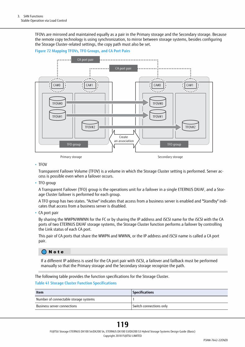
TFOVs are mirrored and maintained equally as a pair in the Primary storage and the Secondary storage. Becausethe remote copy technology is using synchronization, to mirror between storage systems, besides configuringthe Storage Cluster-related settings, the copy path must also be set.
Figure 72 Mapping TFOVs, TFO Groups, and CA Port Pairs
CA#1
Secondary storage
CA#0
Primary storage
TFOV#0
TFOV#1
TFO group TFO group
TFOV#2
CA#1CA#0
TFOV#0
TFOV#1
TFOV#2
CA port pair
CA port pair
Create an association
• TFOV
Transparent Failover Volume (TFOV) is a volume in which the Storage Cluster setting is performed. Server ac-cess is possible even when a failover occurs.
• TFO group
A Transparent Failover (TFO) group is the operations unit for a failover in a single ETERNUS DX/AF, and a Stor-age Cluster failover is performed for each group.
A TFO group has two states. "Active" indicates that access from a business server is enabled and "Standby" indi-cates that access from a business server is disabled.
• CA port pair
By sharing the WWPN/WWNN for the FC or by sharing the IP address and iSCSI name for the iSCSI with the CAports of two ETERNUS DX/AF storage systems, the Storage Cluster function performs a failover by controllingthe Link status of each CA port.
This pair of CA ports that share the WWPN and WWNN, or the IP address and iSCSI name is called a CA portpair.
If a different IP address is used for the CA port pair with iSCSI, a failover and failback must be performedmanually so that the Primary storage and the Secondary storage recognize the path.
The following table provides the function specifications for the Storage Cluster.
Table 41 Storage Cluster Function Specifications
Item Specifications
Number of connectable storage systems 1
Business server connections Switch connections only
3. SAN FunctionsStable Operation via Load Control
119FUJITSU Storage ETERNUS DX100 S4/DX200 S4, ETERNUS DX100 S3/DX200 S3 Hybrid Storage Systems Design Guide (Basic)
Copyright 2018 FUJITSU LIMITEDP3AM-7642-22ENZ0

Item Specifications
Copy path (connection between storage systems) Direct connection and remote connection
The maximum configurable capacity (per storage system) (*1) 2,048TB
Maximum number of TFO groups (per ETERNUS DX) 32
Failover Automatic ¡
Manual ¡
Failback Automatic ¡
Manual ¡
Automatic failover triggers ETERNUS DX/AF failure ¡
Power failure/shutdown ¡
RAID failure/RAID blockage ¡
CA port link down ¡
Storage Cluster Continuous Copy (*2) ¡
¡: Possible, ´: Not possible
*1: The total available capacity of TFOVs for a ETERNUS DX can be expanded by setting an expansion for thetotal capacity of TFOVs. If the installed memory is not sufficient, the expansion setting cannot be per-formed.
For details on setting an expansion for the total capacity of TFOVs, refer to "ETERNUS CLI User's Guide".
*2: Storage Cluster Continuous Copy is an ETERNUS DX/AF function that performs a copy on the Primary storageand the Secondary storage simultaneously, and achieves consistency between the two storage systems.This is achieved by operating Advanced Copy from a TFOV to a TFOV.
• After an error occurs in the Primary storage or RAID group, while the Primary storage is being switched tothe Secondary storage (max. 10 seconds), the Primary and Secondary storage cannot be accessed. There-fore, business applications are expected to have a maximum I/O delay response of 10 seconds.
• Data mirroring between the Primary storage and the Secondary storage is performed by the Storage Clusterduring normal operations. When a Write is performed from the server to the Primary storage, data is alsotransferred to the Secondary storage, and after the transfer is complete a Write completion is returned tothe server. Therefore, when the Storage Cluster is installed, the response degrades during a Write comparedto an environment without the Storage Cluster.
• Using OPC or QuickOPC for Advanced Copy from a TFOV is recommended.
• In environments that use an iSCSI configuration, a switchover of the storage systems that is required for afailover or a failback takes from 30 seconds to 120 seconds to be complete. Server I/O must also be restar-ted in some cases.
• The connection interface of business servers is FC or iSCSI (cannot be mixed). In addition, the switch con-nection topology is supported.
• For details on the required environment for the Storage Cluster (OS, HBA, multipath driver, and cluster soft-ware), refer to "Support Matrix".
3. SAN FunctionsStable Operation via Load Control
120FUJITSU Storage ETERNUS DX100 S4/DX200 S4, ETERNUS DX100 S3/DX200 S3 Hybrid Storage Systems Design Guide (Basic)
Copyright 2018 FUJITSU LIMITEDP3AM-7642-22ENZ0

Data Migration
Storage MigrationStorage Migration is a function that migrates the volume data from an old storage system to volumes in a newstorage system without using a host in cases such as when replacing a storage system.
The migration source storage system and migration destination ETERNUS DX are connected using FC cables. Da-ta read from the target volume in the migration source is written to the migration destination volume in theETERNUS DX.
Since Storage Migration is controlled by ETERNUS DX controllers, no additional software is required.
The connection interface is FC. In addition, the direct connection and switch connection topologies are suppor-ted.
Online Storage Migration and offline Storage Migration are supported.
• Offline method
Stop the server during the data migration. Host access becomes available after the data migration to the mi-gration destination volume is complete. Therefore, this method prevents host access from affecting the ETER-NUS DX and can shorten the time of the migration. This method is suitable for cases requiring quick data mi-gration.
• Online method
Host access becomes available after the data migration to the migration destination volume starts. Operationscan be performed during the data migration. Therefore, this method can shorten the time for the stopped op-eration. This method is suitable for cases requiring continued host access during the data migration.
Figure 73 Storage Migration
ETERNUS DXThe source storage system
FC
Storage Migration
The Storage Migration function migrates whole volumes at the block level. A data migration can be started byspecifying a text file with migration information that is described in a dedicated format from ETERNUS Web GUI.The path between the migration source and the migration destination is called a migration path. The maximumnumber of migration volumes for each migration path is 512.
Up to 16 migration source devices can be specified and up to eight migration paths can be created for each mi-gration source device.
The capacity of a volume that is to be specified as the migration destination area must be larger than the migra-tion source volume capacity.
3. SAN FunctionsData Migration
121FUJITSU Storage ETERNUS DX100 S4/DX200 S4, ETERNUS DX100 S3/DX200 S3 Hybrid Storage Systems Design Guide (Basic)
Copyright 2018 FUJITSU LIMITEDP3AM-7642-22ENZ0
• For online Storage Migration, the capacity of the migration destination volume must be the same as themigration source volume.
• For offline Storage Migration, stop server access to both the migration source volume and the migrationdestination volume during a migration.
For online Storage Migration, stop server access to the migration source volume and the migration destina-tion volume before starting a migration. In addition, do not access the migration source volume from theserver during a migration.
• Online storage migration can be manually resumed on the following volumes after the process (of deletinga copy session) is complete.
- TPV/FTV capacity optimization is running
- Flexible Tier Migration is running
- An Advanced Copy session exists
• For the migration destination device, the FC port mode needs to be switched to "Initiator" and the port pa-rameter also needs to be set.
• Make sure to delete the migration path after Storage Migration is complete.
3. SAN FunctionsData Migration
122FUJITSU Storage ETERNUS DX100 S4/DX200 S4, ETERNUS DX100 S3/DX200 S3 Hybrid Storage Systems Design Guide (Basic)
Copyright 2018 FUJITSU LIMITEDP3AM-7642-22ENZ0
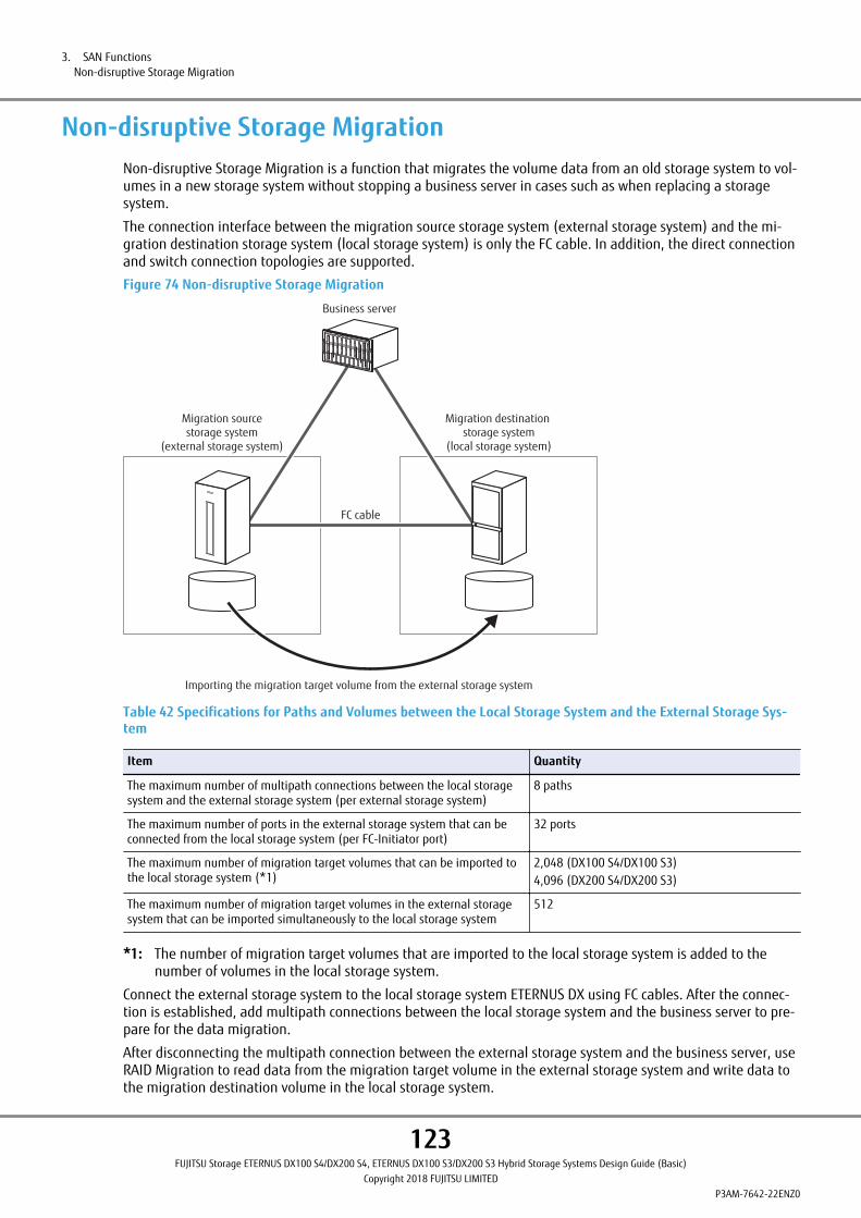
Non-disruptive Storage MigrationNon-disruptive Storage Migration is a function that migrates the volume data from an old storage system to vol-umes in a new storage system without stopping a business server in cases such as when replacing a storagesystem.
The connection interface between the migration source storage system (external storage system) and the mi-gration destination storage system (local storage system) is only the FC cable. In addition, the direct connectionand switch connection topologies are supported.
Figure 74 Non-disruptive Storage Migration
Business server
Migration sourcestorage system
(external storage system)
Migration destination storage system
(local storage system)
FC cable
Importing the migration target volume from the external storage system
Table 42 Specifications for Paths and Volumes between the Local Storage System and the External Storage Sys-tem
Item Quantity
The maximum number of multipath connections between the local storagesystem and the external storage system (per external storage system)
8 paths
The maximum number of ports in the external storage system that can beconnected from the local storage system (per FC-Initiator port)
32 ports
The maximum number of migration target volumes that can be imported tothe local storage system (*1)
2,048 (DX100 S4/DX100 S3)4,096 (DX200 S4/DX200 S3)
The maximum number of migration target volumes in the external storagesystem that can be imported simultaneously to the local storage system
512
*1: The number of migration target volumes that are imported to the local storage system is added to thenumber of volumes in the local storage system.
Connect the external storage system to the local storage system ETERNUS DX using FC cables. After the connec-tion is established, add multipath connections between the local storage system and the business server to pre-pare for the data migration.
After disconnecting the multipath connection between the external storage system and the business server, useRAID Migration to read data from the migration target volume in the external storage system and write data tothe migration destination volume in the local storage system.
3. SAN FunctionsNon-disruptive Storage Migration
123FUJITSU Storage ETERNUS DX100 S4/DX200 S4, ETERNUS DX100 S3/DX200 S3 Hybrid Storage Systems Design Guide (Basic)
Copyright 2018 FUJITSU LIMITEDP3AM-7642-22ENZ0

Data consistency is ensured because the data remains in the migration source volume for consolidated manage-ment during the data migration.
• Only FC ports (connected in the FC-Initiator mode) are supported for connections with external storage sys-tems.
• The Non-disruptive Storage Migration License must be registered to use this function.
For details on the license, contact your sales representative.
• Only data migrations from the external storage system to the local storage system is supported.
Data migrations from the local storage system to the external storage system or between external storagesystems is not supported.
• The local storage system volume returns the same information as the External Volume even after a migra-tion is completed.
• Do not set the copy operation suppression, the cache parameters, and the Volume QoS for the External Vol-ume.
• The functions that can be used for the External Volumes are delete, rename, and RAID migration. Otherfunctions cannot be used until the data migration is successfully completed.
• Migration destination volumes in the local storage cannot be used for Storage Cluster even after the migra-tion is completed.
• Make sure to delete the Non-disruptive Storage Migration License after the Non-disruptive Storage Migra-tion is complete.
3. SAN FunctionsNon-disruptive Storage Migration
124FUJITSU Storage ETERNUS DX100 S4/DX200 S4, ETERNUS DX100 S3/DX200 S3 Hybrid Storage Systems Design Guide (Basic)
Copyright 2018 FUJITSU LIMITEDP3AM-7642-22ENZ0

Server Linkage Functions
Oracle VM Linkage"Oracle VM Manager", which is the user interface of the "Oracle VM" server environment virtualization software,can provision the ETERNUS DX.
"ETERNUS Oracle VM Storage Connect Plug-in" is required to use this function.
The Oracle VM Storage Connect framework enables Oracle VM Manager to directly use the resources and func-tions of the ETERNUS DX in an Oracle VM environment. Native storage services such as Logical Unit Number(LUN) creation, deletion, expansion, and snapshots are supported.
Figure 75 Oracle VM Linkage
ETERNUS DX
SAN
Managementserver
Operation server
• LUN creation, deletion, and expansion• Setting and deletion of the access groups (host affinity)
• Creation of clones
App
OS
App
OS
Oracle VM
ETERNUS Oracle VM Storage Connect Plug-in
App
OS
App
OS
App
OS
Oracle VM Manager
: Linkage software
: ETERNUS DX software (setup tool)
3. SAN FunctionsServer Linkage Functions
125FUJITSU Storage ETERNUS DX100 S4/DX200 S4, ETERNUS DX100 S3/DX200 S3 Hybrid Storage Systems Design Guide (Basic)
Copyright 2018 FUJITSU LIMITEDP3AM-7642-22ENZ0
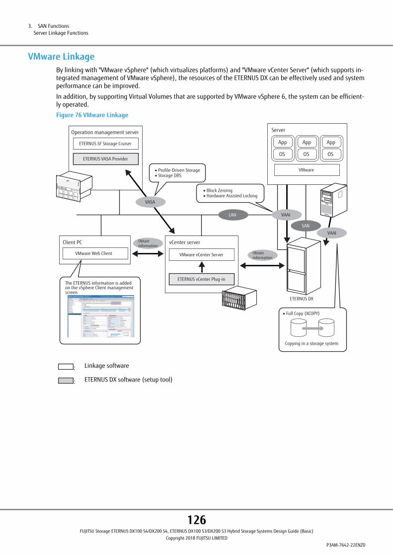
VMware LinkageBy linking with "VMware vSphere" (which virtualizes platforms) and "VMware vCenter Server" (which supports in-tegrated management of VMware vSphere), the resources of the ETERNUS DX can be effectively used and systemperformance can be improved.
In addition, by supporting Virtual Volumes that are supported by VMware vSphere 6, the system can be efficient-ly operated.
Figure 76 VMware Linkage
The ETERNUS information is added on the vSphere Client management screen
SAN
Obtaininformation
Obtaininformation
vCenter serverClient PC
VAAI
VASA
• Full Copy (XCOPY)
Copying in a storage system
VAAI
LAN
ETERNUS VASA Provider
ETERNUS SF Storage Cruiser
Operation management server
ETERNUS vCenter Plug-in
VMware vCenter ServerVMware Web Client
VMware
Server
App
OS
App
OS
App
OS
• Profile-Driven Storage• Storage DRS
• Block Zeroing• Hardware Assisted Locking
ETERNUS DX
: Linkage software
: ETERNUS DX software (setup tool)
3. SAN FunctionsServer Linkage Functions
126FUJITSU Storage ETERNUS DX100 S4/DX200 S4, ETERNUS DX100 S3/DX200 S3 Hybrid Storage Systems Design Guide (Basic)
Copyright 2018 FUJITSU LIMITEDP3AM-7642-22ENZ0

■ VMware VASA
vStorage API for Storage Awareness (VASA) is an API that enables vCenter Server to link with the storage systemand obtain storage system information. With VMware, VASA integrates the virtual infrastructure of the storage,and enhances the Distributed Resource Scheduling (DRS) function and the troubleshooting efficiency.
ETERNUS VASA Provider is required to use the VASA function.
ETERNUS VASA Provider obtains and monitors information from the ETERNUS DX by using functions of ETERNUSSF Storage Cruiser.
• Profile-Driven Storage
The Profile-Driven Storage function classifies volumes according to the service level in order to allocate virtualmachines with the most suitable volumes.
• Distributed Resource Scheduler (Storage DRS)
The Storage DRS function moves original data in virtual machines to the most suitable storage area accordingto the access volume. Storage DRS balances the loads on multiple physical servers in order to eliminate theneed for performance management on each virtual machine.
■ VMware VAAI
vStorage APIs for Array Integration (VAAI) are APIs that improve system performance and scalability by using thestorage system resources more effectively.
The ETERNUS DX supports the following features.
• Full Copy (XCOPY)
Data copying processes can be performed in the ETERNUS DX without the use of a server such as when repli-cating or migrating the virtual machine. With Full Copy (XCOPY), the load on the servers is reduced and thesystem performance is improved.
• Block Zeroing
When allocating storage areas to create new virtual machines, it is necessary to zero out these storage areasfor the initialization process. This process was previously performed on the server side. By performing thisprocess on the ETERNUS DX side instead, the load on the servers is reduced and the dynamic capacity alloca-tion (provisioning) of the virtual machines is accelerated.
• Hardware Assisted Locking
This control function enables the use of smaller blocks that are stored in the ETERNUS DX for exclusive controlof specific storage areas.
Compared to LUN (logical volume) level control that is implemented in "VMware vSphere", enabling accesscontrol in block units minimizes the storage areas that have limited access using exclusive control and im-proves the operational efficiency of virtual machines.
■ VMware vCenter Server
• vCenter linkage
Various information of the ETERNUS DX can be displayed on vSphere Web Client by expanding the user inter-face of VMware Web Client. Because storage side information is more visualized, integrated management ofthe infrastructure under a virtual environment can be realized and usability can be improved.
ETERNUS vCenter Plug-in is required to use this function.
3. SAN FunctionsServer Linkage Functions
127FUJITSU Storage ETERNUS DX100 S4/DX200 S4, ETERNUS DX100 S3/DX200 S3 Hybrid Storage Systems Design Guide (Basic)
Copyright 2018 FUJITSU LIMITEDP3AM-7642-22ENZ0
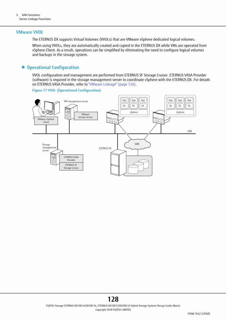
VMware VVOLThe ETERNUS DX supports Virtual Volumes (VVOLs) that are VMware vSphere dedicated logical volumes.
When using VVOLs, they are automatically created and copied in the ETERNUS DX while VMs are operated fromvSphere Client. As a result, operations can be simplified by eliminating the need to configure logical volumesand backups in the storage system.
■ Operational Configuration
VVOL configuration and management are performed from ETERNUS SF Storage Cruiser. ETERNUS VASA Provider(software) is required in the storage management server to coordinate vSphere with the ETERNUS DX. For detailson ETERNUS VASA Provider, refer to "VMware Linkage" (page 126).
Figure 77 VVOL (Operational Configuration)
SAN
ETERNUS DX
VM management server
Storagemanagement server
vSphere
App
OS
App
OS
App
OS
vSphere
App
OS
App
OS
App
OS
LAN
VMware vSphere Client
ETERNUS SFStorage Cruiser
ETERNUS VASAProvider
VMware vCenter Server
3. SAN FunctionsServer Linkage Functions
128FUJITSU Storage ETERNUS DX100 S4/DX200 S4, ETERNUS DX100 S3/DX200 S3 Hybrid Storage Systems Design Guide (Basic)
Copyright 2018 FUJITSU LIMITEDP3AM-7642-22ENZ0

■ System Configuration
vSphere accesses VVOLs through Protocol Endpoints (PE). The server recognizes PEs as logical volumes. VVOLsare created in a pool called a storage container. Storage containers and VVOLs correspond to FTRPs and FTVs ofthe ETERNUS DX.
Figure 78 VVOL (System Configuration)
ETERNUS DX
vSphere
App
OS
App
OS
App
OS
VVOLVVOLVVOL
managementinformation
Storage container
VVOLVVOL
Storage container
PE PE
vSphere
App
OS
App
OS
App
OS
● PE
PEs are control volumes to integrally manage multiple VVOLs.
● Storage Container (VVOL Datastore)
Storage containers are pools for creating VVOLs. The ETERNUS DX uses FTRPs as storage containers. Multiplestorage containers can be created in the ETERNUS DX.
● VVOL
VVOLs are logical volumes that are created in FTRPs. Multiple VVOLs can be created in a storage container.
● Maximum VVOL Capacity
The following shows the maximum capacity that can be used for VVOLs from the maximum Thin ProvisioningPool capacity that is set in the ETERNUS DX.
Table 43 Maximum VVOL Capacity
Item ETERNUS DX100 S4/DX200 S4, ETERNUS DX100 S3/DX200 S3
Maximum TPP capacity (reference) 2,048TB
Maximum VVOL capacity 256TB
3. SAN FunctionsServer Linkage Functions
129FUJITSU Storage ETERNUS DX100 S4/DX200 S4, ETERNUS DX100 S3/DX200 S3 Hybrid Storage Systems Design Guide (Basic)
Copyright 2018 FUJITSU LIMITEDP3AM-7642-22ENZ0

● VVOL Management Information
Additional information called VVOL management information (metadata) is necessary for VVOLs. VVOL manage-ment information is usually synchronized with the master information in the ETERNUS SF Storage Cruiser andsaved to a dedicated FTV within the ETERNUS DX container. The dedicated FTV is automatically created in thestorage container when creating a VVOL.
Table 44 VVOL Management Information Specifications
Item Explanation
Volume name (fixed) $VVOL_META
Volume type FTV
Usage System
Usage details VVOL management information
Capacity 1,040MB
Volume number (of each ETER-NUS DX)
1
• When using VVOLs, LUN#224 to LUN#255 (or LUN numbers that are recognized on the server side) cannotbe used as Virtual Machine File System (VMFS) volumes because they are used for management.
• Use ETERNUS SF Storage Cruiser to change the VVOL settings. Do not change any of the settings from ETER-NUS Web GUI or ETERNUS CLI, except to enable the VVOL function.
• If a VVOL management information dedicated FTV fails because of errors such as a RAID group failure, theVVOL management information dedicated FTV must be recovered by recovering the RAID group, deletingand recreating the VVOL management information dedicated FTV using ETERNUS CLI, and by performing abackup (or synchronizing the VVOL management information) using ETERNUS SF Storage Cruiser.
• If the VVOL management information dedicated FTV is formatted, performing a backup (or synchronizingthe VVOL management information), and recovery of the VVOL management information dedicated FTV us-ing ETERNUS SF Storage Cruiser is required.
• If the FTRP has already been created and the maximum Thin Provisioning Pool capacity and the chunk sizeare changed, before setting VVOL using ETERNUS SF Storage Cruiser, execute the "set vvol-mode" commandof ETERNUS CLI to enable the VVOL function. For details on the chunk size, refer to "Thin Provisioning" (page42).
• When registering multiple FTRPs in a storage container, do not mix FTRPs with different chunk sizes in thesame storage container.
• Before using VMware vSphere Replication, make sure that the ETERNUS DX controller firmware version isV10L80 or later.
3. SAN FunctionsServer Linkage Functions
130FUJITSU Storage ETERNUS DX100 S4/DX200 S4, ETERNUS DX100 S3/DX200 S3 Hybrid Storage Systems Design Guide (Basic)
Copyright 2018 FUJITSU LIMITEDP3AM-7642-22ENZ0

Microsoft LinkageThe ETERNUS DX supports integrated management of virtualized platforms and cloud linkage by using functionsin Windows Server and System Center.
Figure 79 Microsoft Linkage
SAN
SCVMM management server
Instruction
Offloaded Data Transfer (ODX)
Copying in a storage system
SCVMM management console
Hyper-V
App
OS
App
OS
App
OS
Space Reclamation
Windows Server
Server application Backup software
Windows Server
SMI-S
VSS
ETERNUS VSS Hardware Provider
ETERNUS DX
: Linkage software
: ETERNUS DX software (setup tool)
3. SAN FunctionsServer Linkage Functions
131FUJITSU Storage ETERNUS DX100 S4/DX200 S4, ETERNUS DX100 S3/DX200 S3 Hybrid Storage Systems Design Guide (Basic)
Copyright 2018 FUJITSU LIMITEDP3AM-7642-22ENZ0
■ Windows Server
The ETERNUS DX supports the following functions in Windows Server.
• Offloaded Data Transfer (ODX)
The ODX function of Windows Server 2012 or later offloads the processing load for copying and transferringfiles from the CPU of the server to the storage system.
• Thin Provisioning Space Reclamation
The Thin Provisioning Space Reclamation function of Windows Server 2012 or later automatically releasesareas in the storage system that are no longer used by the OS or applications. A notification function for thehost is provided when the amount of allocated blocks of the TPV reaches the threshold.
• Hyper-V
Hyper-V is virtualization software for Windows Server.
By using the Hyper-V virtualized Fibre Channel, direct access to the SAN environment from a guest OS can beperformed. The volumes in the ETERNUS DX can be directly recognized and mounted from the guest OS.
• Volume Shadow Copy Service (VSS)
VSS is performed in combination with the backup software and the server applications that are compatiblewith Windows Server VSS while online backups are performed via the Advanced Copy function for the ETERNUSDX.
ETERNUS VSS Hardware Provider is required to use this function.
SnapOPC+ and QuickOPC can be used as the copy method.
To use the ODX function, the controller firmware version of the ETERNUS DX must be V10L80-2000 or later, orV10L81-2000 or later.
■ System Center Virtual Machine Manager (SCVMM)
System Center is a platform to manage operations of data centers and clouds. This platform also provides anintegrated tool set for the management of applications and services.
SCVMM is a component of System Center 2012 or later that performs integrated management of virtualized envi-ronments. The ETERNUS DX can be managed from SCVMM by using the SMI-S functions of the ETERNUS DX.
OpenStack LinkageETERNUS OpenStack VolumeDriver is a program that supports linkage between the ETERNUS DX and OpenStack.
By using the VolumeDriver for the ETERNUS DX, the ETERNUS DX can be used as a Block Storage for cinder. Creat-ing volumes in the ETERNUS DX and assigning created volumes to VM instances can be performed via an Open-Stack standard interface (Horizon).
3. SAN FunctionsServer Linkage Functions
132FUJITSU Storage ETERNUS DX100 S4/DX200 S4, ETERNUS DX100 S3/DX200 S3 Hybrid Storage Systems Design Guide (Basic)
Copyright 2018 FUJITSU LIMITEDP3AM-7642-22ENZ0

Logical Volume Manager (LVM)The Logical Volume Manager is a management function that groups the save areas in multiple drives and parti-tions and manages these areas as one logical drive. Adding drives and expanding logical volumes can be per-formed without stopping the system. This function can be used on UNIX OSs (includes Linux).
LVM has a snapshot function. This function obtains any logical volume data as a snapshot and saves the snap-shot as a different logical volume.
To use LUNs in the ETERNUS DX to configure an LVM, the LVM can be configured by registering LUNs in theETERNUS DX as physical volumes.
Figure 80 Logical Volume Manager (LVM)
Physical group
RAID group #0 RAID group #1 RAID group #2
Physical volume Physical volume Physical volume
Business server
Logical volume
Volume group
LUN LUN LUN
ETERNUS DX
LVM
3. SAN FunctionsServer Linkage Functions
133FUJITSU Storage ETERNUS DX100 S4/DX200 S4, ETERNUS DX100 S3/DX200 S3 Hybrid Storage Systems Design Guide (Basic)
Copyright 2018 FUJITSU LIMITEDP3AM-7642-22ENZ0

4. Connection Configuration
This chapter explains the connection configuration of the ETERNUS DX.
SAN ConnectionFC, iSCSI, FCoE, and SAS are available as host interfaces. The server and the ETERNUS DX can be connected direct-ly or via a switch.
Host InterfaceThis section describes each host interface.
The supported host interfaces vary between the ETERNUS DX100 S4/DX200 S4 and the ETERNUS DX100 S3/DX200S3. For details about host interfaces, refer to "Overview" of the currently used storage systems.
When switches are used, zoning should be set for the switches to ensure the security of data.
■ Fibre Channel (FC)
The FC connection topologies that are supported are Fibre Channel Arbitrated Loop (FC-AL) and Fabric. Directconnections and switch connections to the servers are available.
The following types of host interfaces are available:
• FC 32Gbit/s
This host interface is supported only for the ETERNUS DX100 S4/DX200 S4.
• FC 16Gbit/s
• FC 8Gbit/s
One of the following transfer rates can be specified:
• For FC 32Gbit/s
- 32Gbit/s
- 16Gbit/s
- 8Gbit/s
• For FC 16Gbit/s
- 16Gbit/s
- 8Gbit/s
- 4Gbit/s
• For FC 8Gbit/s
- 8Gbit/s
- 4Gbit/s
■ iSCSI
Direct connections and switch connections to servers are available.
The following types of host interfaces are available:
• iSCSI 10Gbit/s (10GBASE-SR/10GBASE-CR)
The transfer rate is fixed at 10Gbit/s.
10GBASE-CR is a form of communication that uses Twinax cables and is 10GBASE-SR-compliant.
134FUJITSU Storage ETERNUS DX100 S4/DX200 S4, ETERNUS DX100 S3/DX200 S3 Hybrid Storage Systems Design Guide (Basic)
Copyright 2018 FUJITSU LIMITEDP3AM-7642-22ENZ0
• iSCSI 10Gbit/s (10GBASE-T)
One of the following transfer rates can be specified:
- 10Gbit/s
- 1Gbit/s
• iSCSI 1Gbit/s
In order to maintain iSCSI performance, the iSCSI network should be physically separated from other types ofnetworks (such as networks for Internet access and file transfers).
• Operation Mode
The iSCSI 10Gbit/s operation mode is 10GBASE-SR, 10GBASE-CR, or 10GBASE-T.
The iSCSI 1Gbit/s operation mode is 1000BASE-T Full Duplex (FULL).
• CHAP
CHAP authentication can prevent unauthorized access. The following CHAP authentication methods are sup-ported:
- Unidirectional CHAP
- Bidirectional CHAP
• Tag VLAN
The tag VLAN function is supported. 16 tags (VLAN ID) can be used for each port.
• Jumbo Frame
Enabling Jumbo Frame makes data transfer more efficient by increasing the amount of data that can be trans-ferred for each Frame.
Table 45 Ethernet Frame Capacity (Jumbo Frame Settings)
Jumbo Frame settings Ethernet frame capacity
Enabled Up to 9000 bytes
Disabled Up to 1500 bytes
Server-side CPU load can be reduced by using Jumbo Frame. However, I/O performance may be reduced by10% to 30%.
• Security Architecture for Internet Protocol (IPsec)
The IPsec function is not supported. Connect the server using a LAN switch that has the IPsec function as re-quired.
• Internet Protocol
IPv4 and IPv6 are supported.
• Data Center Bridging (DCB)
iSCSI 10Gbit/s interfaces support the Data Center Bridging (DCB) function.
DCB is an enhanced function of traditional Ethernet and a standard for Fabric connections in data centers. TheDCB function allows connections to Converged Enhanced Ethernet (CEE) environments.
■ FCoE
This host interface is supported only for the ETERNUS DX100 S3/DX200 S3.
Fabric is supported as a connection topology. The transfer rate is 10Gbit/s. When using an FCoE interface, con-nect the ETERNUS DX to the FCoE switch. Direct connections to servers are not supported.
4. Connection ConfigurationSAN Connection
135FUJITSU Storage ETERNUS DX100 S4/DX200 S4, ETERNUS DX100 S3/DX200 S3 Hybrid Storage Systems Design Guide (Basic)
Copyright 2018 FUJITSU LIMITEDP3AM-7642-22ENZ0

■ SAS
Simple, cost effective, and high performance network storage environment can be configured. Direct connec-tions and switch connections to servers are available.
The following types of host interfaces are available:
• SAS 12Gbit/s
This host interface is supported only for the ETERNUS DX100 S4/DX200 S4.
• SAS 6Gbit/s
This host interface is supported only for the ETERNUS DX100 S3/DX200 S3.
One of the following transfer rates can be specified:
• For SAS 12Gbit/s
- 12Gbit/s
- 6Gbit/s
- 3Gbit/s
• For SAS 6Gbit/s
- 6Gbit/s
- 3Gbit/s
- 1.5Gbit/s
4. Connection ConfigurationSAN Connection
136FUJITSU Storage ETERNUS DX100 S4/DX200 S4, ETERNUS DX100 S3/DX200 S3 Hybrid Storage Systems Design Guide (Basic)
Copyright 2018 FUJITSU LIMITEDP3AM-7642-22ENZ0

Access MethodThis section explains the connection configurations between server Host Bus Adapters (HBAs) and ETERNUS DXhost interface ports.
■ Single Path Connection
A single path configuration connects the ETERNUS DX to a server via a single path.
The server cannot access an ETERNUS DX when a component (such as a controller, HBA, switch, or cable) on thepath has a problem. The system must be stopped when a failed component on a path needs to be replaced orwhen the controller firmware needs to be updated.
In a single path connection configuration, the path failover and load balancing functions are not supported.
A multipath connection configuration is recommended to maintain availability when a problem occurs.
Figure 81 Single Path Connection (When a SAN Connection Is Used — Direct Connection)
Server
HBA
Server
HBA
ETERNUS DX
CM#0
CA
PortPort
CA
CM#1
Port Port
Figure 82 Single Path Connection (When a SAN Connection Is Used — Switch Connection)
Server
HBA
Server
HBA
Server
HBA
Switch
ETERNUS DX
CM#0
CA
PortPort
CA
CM#1
Port Port
4. Connection ConfigurationSAN Connection
137FUJITSU Storage ETERNUS DX100 S4/DX200 S4, ETERNUS DX100 S3/DX200 S3 Hybrid Storage Systems Design Guide (Basic)
Copyright 2018 FUJITSU LIMITEDP3AM-7642-22ENZ0

■ Multipath Configuration
A multipath configuration connects the ETERNUS DX to a server via multiple paths (multipath). System reliabilityis improved due to the path redundancy.
If a path fails, access can continue by using the path failover function that switches access from the failed pathto another path.
Figure 83 Multipath Connection (When a SAN Connection Is Used — Basic Connection Configuration)
Server
HBA HBA
Server
HBAHBA
ETERNUS DX
CM#0
PortPort
CA#0 CA#0
CM#1
Port Port
Figure 84 Multipath Connection (When a SAN Connection Is Used — Switch Connection)
Server
HBA HBA
Server
HBA HBA
Server
HBA HBA
Switch Switch
ETERNUS DX
CM#0
Port
CA
PortPort
CA
Port
CM#1
4. Connection ConfigurationSAN Connection
138FUJITSU Storage ETERNUS DX100 S4/DX200 S4, ETERNUS DX100 S3/DX200 S3 Hybrid Storage Systems Design Guide (Basic)
Copyright 2018 FUJITSU LIMITEDP3AM-7642-22ENZ0
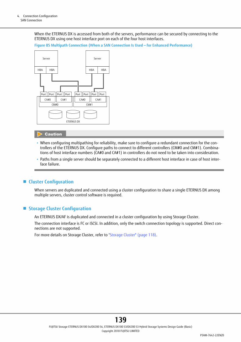
When the ETERNUS DX is accessed from both of the servers, performance can be secured by connecting to theETERNUS DX using one host interface port on each of the four host interfaces.
Figure 85 Multipath Connection (When a SAN Connection Is Used — for Enhanced Performance)
Server
HBA HBA HBA
Server
HBA
ETERNUS DX
Port
CM#0
Port Port
CA#0 CA#1 CA#0 CA#1
CM#1
PortPort Port Port Port
• When configuring multipathing for reliability, make sure to configure a redundant connection for the con-trollers of the ETERNUS DX. Configure paths to connect to different controllers (CM#0 and CM#1). Combina-tions of host interface numbers (CA#0 and CA#1) in controllers do not need to be taken into consideration.
• Paths from a single server should be separately connected to a different host interface in case of host inter-face failure.
■ Cluster Configuration
When servers are duplicated and connected using a cluster configuration to share a single ETERNUS DX amongmultiple servers, cluster control software is required.
■ Storage Cluster Configuration
An ETERNUS DX/AF is duplicated and connected in a cluster configuration by using Storage Cluster.
The connection interface is FC or iSCSI. In addition, only the switch connection topology is supported. Direct con-nections are not supported.
For more details on Storage Cluster, refer to "Storage Cluster" (page 118).
4. Connection ConfigurationSAN Connection
139FUJITSU Storage ETERNUS DX100 S4/DX200 S4, ETERNUS DX100 S3/DX200 S3 Hybrid Storage Systems Design Guide (Basic)
Copyright 2018 FUJITSU LIMITEDP3AM-7642-22ENZ0
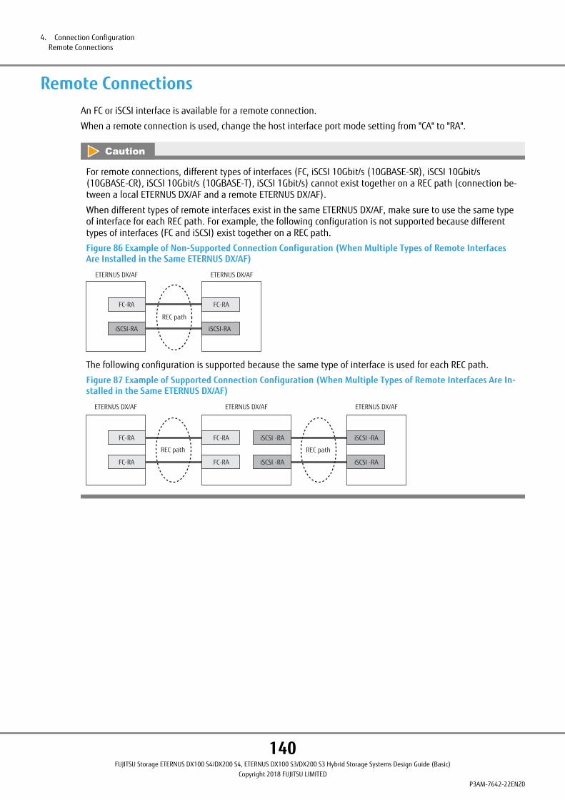
Remote ConnectionsAn FC or iSCSI interface is available for a remote connection.
When a remote connection is used, change the host interface port mode setting from "CA" to "RA".
For remote connections, different types of interfaces (FC, iSCSI 10Gbit/s (10GBASE-SR), iSCSI 10Gbit/s(10GBASE-CR), iSCSI 10Gbit/s (10GBASE-T), iSCSI 1Gbit/s) cannot exist together on a REC path (connection be-tween a local ETERNUS DX/AF and a remote ETERNUS DX/AF).
When different types of remote interfaces exist in the same ETERNUS DX/AF, make sure to use the same typeof interface for each REC path. For example, the following configuration is not supported because differenttypes of interfaces (FC and iSCSI) exist together on a REC path.
Figure 86 Example of Non-Supported Connection Configuration (When Multiple Types of Remote InterfacesAre Installed in the Same ETERNUS DX/AF)
FC-RA
iSCSI-RA
FC-RA
REC path
iSCSI-RA
ETERNUS DX/AF ETERNUS DX/AF
The following configuration is supported because the same type of interface is used for each REC path.
Figure 87 Example of Supported Connection Configuration (When Multiple Types of Remote Interfaces Are In-stalled in the Same ETERNUS DX/AF)
FC-RA
FC-RA
ETERNUS DX/AF ETERNUS DX/AF ETERNUS DX/AF
FC-RA
FC-RA
iSCSI -RA
iSCSI -RA
iSCSI -RA
iSCSI -RA
REC path REC path
4. Connection ConfigurationRemote Connections
140FUJITSU Storage ETERNUS DX100 S4/DX200 S4, ETERNUS DX100 S3/DX200 S3 Hybrid Storage Systems Design Guide (Basic)
Copyright 2018 FUJITSU LIMITEDP3AM-7642-22ENZ0
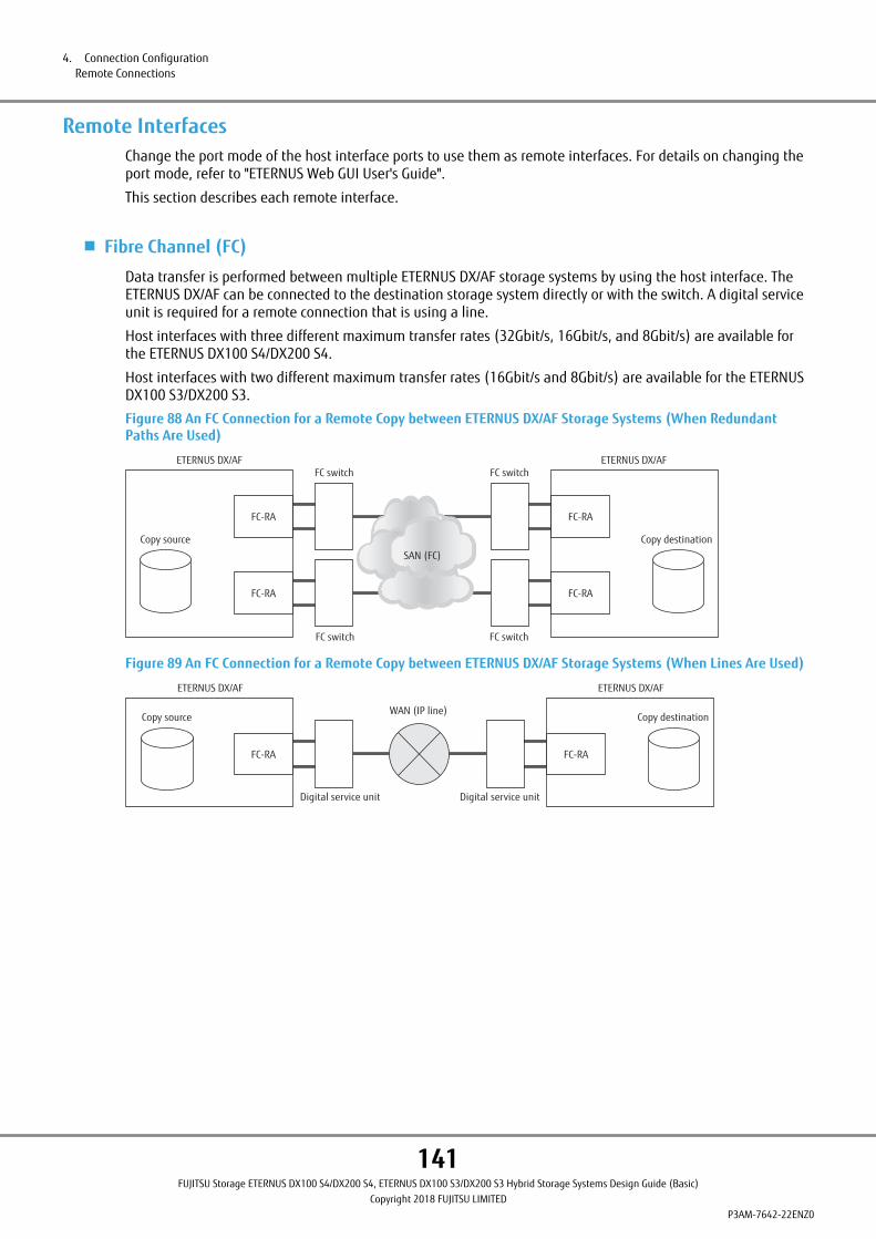
Remote InterfacesChange the port mode of the host interface ports to use them as remote interfaces. For details on changing theport mode, refer to "ETERNUS Web GUI User's Guide".
This section describes each remote interface.
■ Fibre Channel (FC)
Data transfer is performed between multiple ETERNUS DX/AF storage systems by using the host interface. TheETERNUS DX/AF can be connected to the destination storage system directly or with the switch. A digital serviceunit is required for a remote connection that is using a line.
Host interfaces with three different maximum transfer rates (32Gbit/s, 16Gbit/s, and 8Gbit/s) are available forthe ETERNUS DX100 S4/DX200 S4.
Host interfaces with two different maximum transfer rates (16Gbit/s and 8Gbit/s) are available for the ETERNUSDX100 S3/DX200 S3.
Figure 88 An FC Connection for a Remote Copy between ETERNUS DX/AF Storage Systems (When RedundantPaths Are Used)
FC-RA
Copy source
ETERNUS DX/AFFC switch
FC switch
SAN (FC)
FC-RA
FC-RA
Copy destination
FC-RA
ETERNUS DX/AFFC switch
FC switch
Figure 89 An FC Connection for a Remote Copy between ETERNUS DX/AF Storage Systems (When Lines Are Used)
Copy source
ETERNUS DX/AF
Digital service unit
FC-RA
Copy destination
FC-RA
ETERNUS DX/AF
WAN (IP line)
Digital service unit
4. Connection ConfigurationRemote Connections
141FUJITSU Storage ETERNUS DX100 S4/DX200 S4, ETERNUS DX100 S3/DX200 S3 Hybrid Storage Systems Design Guide (Basic)
Copyright 2018 FUJITSU LIMITEDP3AM-7642-22ENZ0
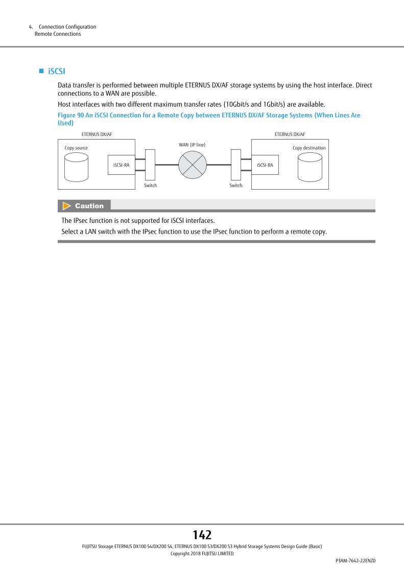
■ iSCSI
Data transfer is performed between multiple ETERNUS DX/AF storage systems by using the host interface. Directconnections to a WAN are possible.
Host interfaces with two different maximum transfer rates (10Gbit/s and 1Gbit/s) are available.
Figure 90 An iSCSI Connection for a Remote Copy between ETERNUS DX/AF Storage Systems (When Lines AreUsed)
Copy source
ETERNUS DX/AF
Switch
iSCSI-RA
Copy destination
iSCSI-RA
ETERNUS DX/AF
WAN (IP line)
Switch
The IPsec function is not supported for iSCSI interfaces.
Select a LAN switch with the IPsec function to use the IPsec function to perform a remote copy.
4. Connection ConfigurationRemote Connections
142FUJITSU Storage ETERNUS DX100 S4/DX200 S4, ETERNUS DX100 S3/DX200 S3 Hybrid Storage Systems Design Guide (Basic)
Copyright 2018 FUJITSU LIMITEDP3AM-7642-22ENZ0
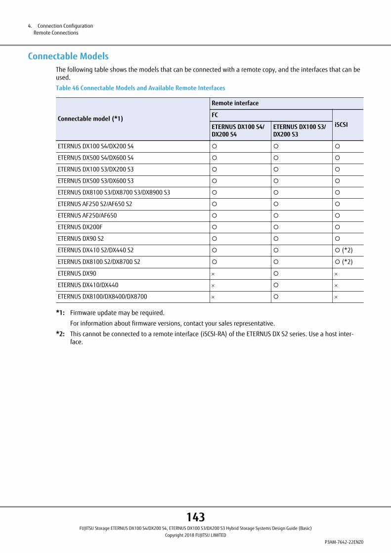
Connectable ModelsThe following table shows the models that can be connected with a remote copy, and the interfaces that can beused.
Table 46 Connectable Models and Available Remote Interfaces
Connectable model (*1)
Remote interface
FCiSCSIETERNUS DX100 S4/
DX200 S4ETERNUS DX100 S3/DX200 S3
ETERNUS DX100 S4/DX200 S4 ¡ ¡ ¡
ETERNUS DX500 S4/DX600 S4 ¡ ¡ ¡
ETERNUS DX100 S3/DX200 S3 ¡ ¡ ¡
ETERNUS DX500 S3/DX600 S3 ¡ ¡ ¡
ETERNUS DX8100 S3/DX8700 S3/DX8900 S3 ¡ ¡ ¡
ETERNUS AF250 S2/AF650 S2 ¡ ¡ ¡
ETERNUS AF250/AF650 ¡ ¡ ¡
ETERNUS DX200F ¡ ¡ ¡
ETERNUS DX90 S2 ¡ ¡ ¡
ETERNUS DX410 S2/DX440 S2 ¡ ¡ ¡ (*2)
ETERNUS DX8100 S2/DX8700 S2 ¡ ¡ ¡ (*2)
ETERNUS DX90 ´ ¡ ´
ETERNUS DX410/DX440 ´ ¡ ´
ETERNUS DX8100/DX8400/DX8700 ´ ¡ ´
*1: Firmware update may be required.
For information about firmware versions, contact your sales representative.
*2: This cannot be connected to a remote interface (iSCSI-RA) of the ETERNUS DX S2 series. Use a host inter-face.
4. Connection ConfigurationRemote Connections
143FUJITSU Storage ETERNUS DX100 S4/DX200 S4, ETERNUS DX100 S3/DX200 S3 Hybrid Storage Systems Design Guide (Basic)
Copyright 2018 FUJITSU LIMITEDP3AM-7642-22ENZ0

LAN ConnectionThe ETERNUS DX requires a LAN connection for operation management.
In addition, information such as ETERNUS DX failures is notified to the remote support center.
Make sure to connect each controller to the LAN for operation management.
Specifications for the LAN ports of the ETERNUS DX are shown below.
• Operation Mode
Ethernet (1000BASE-T/100BASE-TX/10BASE-T)
• Internet Protocol
IPv4 and IPv6 are supported.
■ IP Addresses for the ETERNUS DX
In order to connect to the LAN for operation management, an IP address for ETERNUS DX must be prepared inadvance.
LAN for Operation Management (MNT Port)In an ETERNUS DX, the system administrator logs on to the ETERNUS DX via a LAN to set the RAID configuration,manage operations, and perform maintenance.
In addition, the failures that occur in the ETERNUS DX are notified to the remote support center. The remotesupport uses MNT ports for a network connection by default. In this situation, the network connection for theremote support is transferred via the LAN for operation management. When the network connection for the re-mote support needs to be separated from the LAN for operation management, refer to "LAN for Remote Support(RMT Port)" (page 146) and use the RMT ports to connect to the remote support center via a different network.
4. Connection ConfigurationLAN Connection
144FUJITSU Storage ETERNUS DX100 S4/DX200 S4, ETERNUS DX100 S3/DX200 S3 Hybrid Storage Systems Design Guide (Basic)
Copyright 2018 FUJITSU LIMITEDP3AM-7642-22ENZ0

■ Connection Configurations
MNT ports are used for connecting a LAN for operation management.
Figure 91 Connection Example without a Dedicated Remote Support Port
Remote support center
RMT ports are not used.
LAN switch
NTP server
Authenticationserver
Syslog server
ETERNUS DX
Controller enclosure
RMT
MN
T
CM#0
RMT
CM#1
IP address A
MN
T
Administrationterminal
SNMPmanager
E-mail server
LAN for operation management
The following figure provides connection examples for when setting the IP address of the Slave CM.
Figure 92 Connection Example When the IP Address of the Slave CM Is Set (and a Dedicated Remote SupportPort Is Not Used)
Remote support center
RMT ports are not used.
The IP addresses of the Master CM and the Slave CM are set.
LAN switch
SNMPmanager NTP serverE-mail server
Authentication serverSyslog server
LAN for operation management
ETERNUS DX
Controller enclosure
RMT
MN
T
CM#0
RMT
CM#1
Administrationterminal
IP address BIP address A
MN
T
4. Connection ConfigurationLAN Connection
145FUJITSU Storage ETERNUS DX100 S4/DX200 S4, ETERNUS DX100 S3/DX200 S3 Hybrid Storage Systems Design Guide (Basic)
Copyright 2018 FUJITSU LIMITEDP3AM-7642-22ENZ0
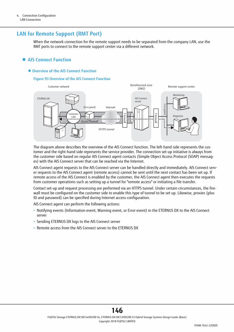
LAN for Remote Support (RMT Port)When the network connection for the remote support needs to be separated from the company LAN, use theRMT ports to connect to the remote support center via a different network.
■ AIS Connect Function
● Overview of the AIS Connect Function
Figure 93 Overview of the AIS Connect Function
ETERNUS DX
Encrypted
Diagnosis
MonitoringAIS Connect server
Remote support centerDemilitarized zone(DMZ)
Customer network
Internet
CustomerLAN
[Encrypted]
Access firewall
HTTPS tunnel
Firewall
Firewall
The diagram above describes the overview of the AIS Connect function. The left-hand side represents the cus-tomer and the right-hand side represents the service provider. The connection set-up initiative is always fromthe customer side based on regular AIS Connect agent contacts (Simple Object Access Protocol (SOAP) messag-es) with the AIS Connect server that can be reached via the Internet.
AIS Connect agent requests to the AIS Connect server can be handled directly and immediately. AIS Connect serv-er requests to the AIS Connect agent (remote access) cannot be sent until the next contact has been set up. Ifremote access of the AIS Connect is enabled by the customer, the AIS Connect agent then executes the requestsfrom customer operations such as setting up a tunnel for "remote access" or initiating a file transfer.
Contact set-up and request processing are performed via an HTTPS tunnel. Under certain circumstances, the fire-wall must be configured on the customer side to enable this type of tunnel to be set up. Likewise, proxies (plusID and password) can be specified during Internet access configuration.
AIS Connect agent can perform the following actions:
• Notifying events (Information event, Warning event, or Error event) in the ETERNUS DX to the AIS Connectserver
• Sending ETERNUS DX logs to the AIS Connect server
• Remote access from the AIS Connect server to the ETERNUS DX
4. Connection ConfigurationLAN Connection
146FUJITSU Storage ETERNUS DX100 S4/DX200 S4, ETERNUS DX100 S3/DX200 S3 Hybrid Storage Systems Design Guide (Basic)
Copyright 2018 FUJITSU LIMITEDP3AM-7642-22ENZ0

● Security Features
Figure 94 Security Features
ETERNUS DXbehind a firewall
AIS Connect serverFirewall
Allowed
Rejected
Connection from an AIS Connect agent to the AIS Connect server can be set up via a SOAP message that is basedon HTTPS. Access can only be initiated by an AIS Connect agent at the ETERNUS DX site of the customer as illus-trated by the diagram above. The AIS Connect server offers a certificate and the AIS Connect agent verifies thiscertificate for every connection setup. All transferred data is protected against spy-out and manipulation.
For setup procedure for remote support (by AIS Connect), refer to "Configuration Guide (Basic)".
In some regions, the usage of AIS Connect is limited to contract customers.
Contact the Support Department for details.
■ REMCS
For setup procedure for remote support (by REMCS), refer to "Configuration Guide (Basic)".
The sections that are shown below explain how to set the ETERNUS DX for remote support. For details on thesettings, refer to "Configuration Guide (Web GUI)".
4. Connection ConfigurationLAN Connection
147FUJITSU Storage ETERNUS DX100 S4/DX200 S4, ETERNUS DX100 S3/DX200 S3 Hybrid Storage Systems Design Guide (Basic)
Copyright 2018 FUJITSU LIMITEDP3AM-7642-22ENZ0

■ Connection Configurations
For the ETERNUS DX, two IP addresses are required (one IP address for the MNT port and one IP address for theRMT port).
Figure 95 Connection Example with a Dedicated Remote Support Port
Different LANs are used for MNT ports and RMT ports.
Syslog serverLAN switch
ETERNUS DX
Remote support centerController enclosure
RMT
CM#0
RMT
CM#1
Router
IP address C IP address A
MN
T
MN
T
Administrationterminal
SNMPmanager E-mail server NTP server
Authenticationserver
LAN for operation management
4. Connection ConfigurationLAN Connection
148FUJITSU Storage ETERNUS DX100 S4/DX200 S4, ETERNUS DX100 S3/DX200 S3 Hybrid Storage Systems Design Guide (Basic)
Copyright 2018 FUJITSU LIMITEDP3AM-7642-22ENZ0

The following figure provides connection examples and explains the necessary preparation for when the IPaddress of the Slave CM is set.
For the ETERNUS DX, three IP addresses are required (two IP addresses for the MNT ports and one IP addressfor the RMT port).
Figure 96 Connection Example When the IP Address of the Slave CM Is Set (and a Dedicated Remote SupportPort Is Used)
Different LANs are used for MNT ports and RMT ports.The IP addresses of the Master CM and the Slave CM are set.
LAN for operation management
LAN switch
ETERNUS DX
Controller enclosure
RMT
MN
T
CM#0
RMT
CM#1
Router
Remote support center
SNMPmanager NTP serverE-mail server
Authenticationserver
Syslog server
Administrationterminal
IP address A IP address BIP address C
MN
T
LAN Control (Master CM/Slave CM)This section explains how the LAN control controller of the ETERNUS DX operates.
When an ETERNUS DX has two controllers, the controller (CM) that is given the authority to manage the LAN iscalled the Master CM and the other CM is called the Slave CM.
When an error occurs in the Master CM or LAN, the Master CM is switched automatically.
4. Connection ConfigurationLAN Connection
149FUJITSU Storage ETERNUS DX100 S4/DX200 S4, ETERNUS DX100 S3/DX200 S3 Hybrid Storage Systems Design Guide (Basic)
Copyright 2018 FUJITSU LIMITEDP3AM-7642-22ENZ0

IP addresses of the LAN ports are not assigned to each CM. These IP addresses are assigned to the role of masteror slave. If the Master CM is switched, the same IP addresses are reused. Therefore, even if the Master CM isswitched and the physical port is changed, access can be maintained via the same IP addresses. The MAC ad-dress is not inherited.
Figure 97 LAN Control (Switching of the Master CM)
Controller enclosure
MN
T
CM#0
Master CM
MN
T
CM#1
Slave CM
Controller enclosure
MN
T
RMT
RMT
RMT
RMT
CM#0
Slave CM
MN
T
CM#1
Master CM
IP address A
IP address A
ETERNUS DX
ETERNUS DX
The Master CM is switched.
CM#0has failed
When the Master CM isswitched, the IP addresses ofthe previous Master CM aretaken over by the newMaster CM.
• Each CM has an LED that lights up green to identify when it is the Master CM.
• Setting the IP address of the Slave CM ensures that ETERNUS Web GUI or ETERNUS CLI can be used from theSlave CM if an error occurs on the LAN path for the Master CM.
The Master CM and the Slave CM perform different functions. The Slave CM can only switch the Master CMand display the status of the ETERNUS DX.
The IP address of the Slave CM does not need to be set for normal operation.
Figure 98 LAN Control (When the IP Address of the Slave CM Is Set)
Controller enclosure
MN
T
CM#0 CM#1
RMT
RMT
MN
T
ETERNUS DX
LAN patherror
Master CM Slave CM
IP address A IP address B
The IP address of the Slave CM isused to switch the Master CM anddisplay the status of the ETERNUS DX.
4. Connection ConfigurationLAN Connection
150FUJITSU Storage ETERNUS DX100 S4/DX200 S4, ETERNUS DX100 S3/DX200 S3 Hybrid Storage Systems Design Guide (Basic)
Copyright 2018 FUJITSU LIMITEDP3AM-7642-22ENZ0

Network Communication ProtocolsThe usable LAN ports and functions are different depending on the usage and protocol.
The following table shows how the LAN ports may be used (by usage and protocol).
Table 47 LAN Port Availability
Usage Protocol tcp / udp Portnumber Direction
Master CM Slave CMRemarks
MNT RMT MNT RMT
ETERNUS Web GUI http /https
tcp 80 / 443 from ¡ ¡ △ (*1) △ (*1) Accessedfrom aWebbrowser
ETERNUS CLI telnet /ssh
tcp 23 / 22 from ¡ ¡ △ (*1) △ (*1) −
ftp (cli-ent)
tcp 21 to ¡ ¡ △ (*1) △ (*1) −
SNMP agent snmp udp 161 from ¡ ¡ ¡ ¡ −
trap snmp trap udp Must beset
to ¡ (*2) ¡ (*2) ´ ´ −
SMI-S http /https
tcp 5988 /5989
from ¡ ´ ´ ´ Used forSMI-S cli-ent com-munica-tion
http /https
tcp Must beset
to ¡ ´ ´ ´ Used foreventcommuni-cationswith theSMI-S lis-tener, etc.
SLP tcp 427 from/to ¡ ´ ´ ´ Used forservice in-quirycommuni-cationfrom theSMI-S cli-ent
E-mail smtp (cli-ent)
tcp 25 (*3) to ¡ (*2) ¡ (*2) ´ ´ Used forfailurenotifica-tion, etc.
NTP NTP (cli-ent)
udp 123 to ¡ (*2) ¡ (*2) ´ ´ −
REMCS(remote support)
smtp tcp Must beset
to ¡ (*2) ¡ (*2) ´ ´ Used forfailurenotifica-tion, etc.
http (cli-ent)
tcp Must beset
to ¡ (*2) ¡ (*2) ´ ´ Used forfirmwaredown-load, etc.
AIS Connect (remotesupport)
https (cli-ent)
tcp 443 to ¡ (*2) ¡ (*2) ´ ´ —
4. Connection ConfigurationLAN Connection
151FUJITSU Storage ETERNUS DX100 S4/DX200 S4, ETERNUS DX100 S3/DX200 S3 Hybrid Storage Systems Design Guide (Basic)
Copyright 2018 FUJITSU LIMITEDP3AM-7642-22ENZ0
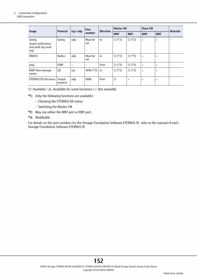
Usage Protocol tcp / udp Portnumber Direction
Master CM Slave CMRemarks
MNT RMT MNT RMT
Syslog(event notificationand audit log send-ing)
Syslog udp Must beset
to ¡ (*2) ¡ (*2) ´ ´ −
RADIUS Radius udp Must beset
to ¡ (*2) ¡ (*2) ´ ´ −
ping ICMP − − from ¡ (*2) ¡ (*2) ´ ´ −
KMIP (key manage-ment)
SSL tcp 5696 (*3) to ¡ (*2) ¡ (*2) ´ ´ −
ETERNUS DX Discovery Uniqueprotocol
udp 9686 from ¡ ´ ´ ´ −
¡: Available / △: Available for some functions / ´: Not available
*1: Only the following functions are available:
• Checking the ETERNUS DX status
• Switching the Master CM
*2: May use either the MNT port or RMT port.
*3: Modifiable
For details on the port numbers for the Storage Foundation Software ETERNUS SF, refer to the manual of eachStorage Foundation Software ETERNUS SF.
4. Connection ConfigurationLAN Connection
152FUJITSU Storage ETERNUS DX100 S4/DX200 S4, ETERNUS DX100 S3/DX200 S3 Hybrid Storage Systems Design Guide (Basic)
Copyright 2018 FUJITSU LIMITEDP3AM-7642-22ENZ0
Power Supply ConnectionConnect the power cords (AC cables) of the ETERNUS DX to the power sockets, the UPS sockets, or the powercontrol unit sockets.
For details about the types and the number of power sockets that can be used, refer to "Power Socket Specifica-tions" in "Site Planning Guide".
Input Power Supply LinesFor details on input power supply lines, refer to "Site Planning Guide".
UPS ConnectionIt is recommended that an Uninterruptible Power Supply System (UPS) is used as the power supply source for theETERNUS DX to cope with power outages and momentary voltage drops in the normal power supply.
Note that when connecting an ETERNUS DX to a single UPS, the total value of the power requirements for all theenclosures must not exceed the UPS output capacity.
When one of the power supply lines fails for redundantly configured UPS units with two power supply lines, all ofthe power for the ETERNUS DX must be supplied from the other line. Select a UPS that can supply sufficient pow-er so that the total value of the power requirements does not exceed the UPS output capacity in case only onepower supply line is available.
For details about the necessary UPS output capacity, refer to the specifications of the UPS that is used.
A UPS must satisfy the following conditions:
● Rating Capacity
Secure a sufficient rating capacity for the total value of the maximum power requirements for the enclosuresthat are to be installed.
To find the maximum power level requirements for each enclosure, refer to "Installation Specifications" in "SitePlanning Guide".
● Supply Time
The total time for the server to shut down and for the ETERNUS DX to power off must be taken into considerationfor the power supply time of the battery.
● Switching Time during Power Failure
The normal power supply must be switched to UPS output within 15ms after a power failure occurs.
● Socket Type
If the power plug type and the socket type of the UPS do not match, it is necessary to equip the UPS (AC output)with an appropriate type of socket. Request a qualified electrician to perform the necessary work to make termi-nal block connections available.
● Power Supply Configuration
If a UPS is used, make sure that it supplies power to all the enclosures.
Configurations where the controller enclosure is powered by the UPS while the drive enclosures are powered di-rectly from AC are not supported.
4. Connection ConfigurationPower Supply Connection
153FUJITSU Storage ETERNUS DX100 S4/DX200 S4, ETERNUS DX100 S3/DX200 S3 Hybrid Storage Systems Design Guide (Basic)
Copyright 2018 FUJITSU LIMITEDP3AM-7642-22ENZ0

Power Synchronized ConnectionsThis section describes the connections to automatically control powering the ETERNUS DX on and off with a serv-er.
In order to control powering the ETERNUS DX on and off with servers, the power control of the ETERNUS DX mustbe linked with all of the connected servers.
Power Synchronized Connections (PWC)
■ Power Synchronized Unit
A power synchronized unit enables the ETERNUS DX to be powered on and off with a server. The power synchron-ized unit detects changes in the AC power output of a UPS unit that is connected to a server (server UPS unit)and automatically turns on and off the ETERNUS DX. In addition to server UPS units, units that control the ACsocket power output can also be connected. When three or more servers are connected, power can be synchron-ized by adding an AC sensor unit.
● Power Synchronization via a Server UPS Connection
The power synchronized unit detects the AC power output of the target devices for power synchronization andcommands the ETERNUS DX to synchronize the power with the target devices.
When the power synchronized unit detects the AC power output of any server UPS unit, the power synchronizedunit commands the ETERNUS DX to turn on.
When the power synchronized unit does not detect AC power output in any of the server UPS units, the powersynchronized unit commands the ETERNUS DX to turn off.
The server UPS unit must have a function in the management software that controls the AC power output ac-cording to when the server powers on and off. The server UPS unit must have one unused outlet to connect tothe power synchronized unit.
• When connecting one or two servers
Figure 99 Power Supply Control Using a Power Synchronized Unit (When Connecting One or Two Servers)
RS232C cable
Server
ETERNUS DX
PWC
UPS setting
Power synchronized unit
PWC
UPS
UPSmanagement
software
An instruction is issued to turn on/off the ETERNUS DX when AC output/no AC output is detected.
Turns on: 1Turns off: 2
Turns on: 2Turns off: 1
3
4
4. Connection ConfigurationPower Synchronized Connections
154FUJITSU Storage ETERNUS DX100 S4/DX200 S4, ETERNUS DX100 S3/DX200 S3 Hybrid Storage Systems Design Guide (Basic)
Copyright 2018 FUJITSU LIMITEDP3AM-7642-22ENZ0

Powering on sequence
1 Power on of all the server UPS units
2 Server startup
The server OS startup is suspended until the ETERNUS DX startup is complete (*1).
3 Issuance of command to turn on the ETERNUS DX from the power synchronized unit
4 ETERNUS DX startup
*1: The server must be set to suspend server OS startup until the ETERNUS DX startup is complete.
Powering off sequence
1 Shutdown of all the servers
2 Shutdown of all the server UPS units
3 Issuance of command to turn off the ETERNUS DX from the power synchronized unit
4 ETERNUS DX shutdown
4. Connection ConfigurationPower Synchronized Connections
155FUJITSU Storage ETERNUS DX100 S4/DX200 S4, ETERNUS DX100 S3/DX200 S3 Hybrid Storage Systems Design Guide (Basic)
Copyright 2018 FUJITSU LIMITEDP3AM-7642-22ENZ0

• When connecting three or more servers
Figure 100 Power Supply Control Using a Power Synchronized Unit (When Connecting Three or More Servers)
ETERNUS DX
PWC
Power synchronizedunit#0
UPS unit forServer#0
PWC PWC
ETERNUS DX
PWC
Server#2
AC sensorunit#1
Server#3
Server#0
UPS unit forServer#1
Server#1
UPS unit forServer#2
UPS unit forServer#3
AC sensorunit#0
Turns on: 1Turns off: 2
Turns on: 2Turns off: 1
4
4
3
Powering on sequence
1 Power on of all the server UPS units
2 Server startup
The server OS startup is suspended until the ETERNUS DX startup is complete (*1).
3 Issuance of command to turn on the ETERNUS DX from the power synchronized unit
4 ETERNUS DX startup
*1: The server must be set to suspend server OS startup until the ETERNUS DX startup is complete.
4. Connection ConfigurationPower Synchronized Connections
156FUJITSU Storage ETERNUS DX100 S4/DX200 S4, ETERNUS DX100 S3/DX200 S3 Hybrid Storage Systems Design Guide (Basic)
Copyright 2018 FUJITSU LIMITEDP3AM-7642-22ENZ0
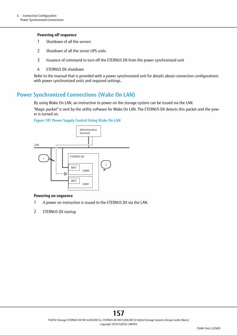
Powering off sequence
1 Shutdown of all the servers
2 Shutdown of all the server UPS units
3 Issuance of command to turn off the ETERNUS DX from the power synchronized unit
4 ETERNUS DX shutdown
Refer to the manual that is provided with a power synchronized unit for details about connection configurationswith power synchronized units and required settings.
Power Synchronized Connections (Wake On LAN)By using Wake On LAN, an instruction to power on the storage system can be issued via the LAN.
"Magic packet" is sent by the utility software for Wake On LAN. The ETERNUS DX detects this packet and the pow-er is turned on.
Figure 101 Power Supply Control Using Wake On LAN
Administration Terminal
LAN
MN T
MN T
ETERNUS DX
CM#0
CM#1
2
1
Powering on sequence
1 A power on instruction is issued to the ETERNUS DX via the LAN.
2 ETERNUS DX startup
4. Connection ConfigurationPower Synchronized Connections
157FUJITSU Storage ETERNUS DX100 S4/DX200 S4, ETERNUS DX100 S3/DX200 S3 Hybrid Storage Systems Design Guide (Basic)
Copyright 2018 FUJITSU LIMITEDP3AM-7642-22ENZ0

5. Hardware Configurations
Multiple options can be selected in the ETERNUS DX according to the customer's requirements. This chapter de-scribes the installation conditions and standard installation rules for each component.
158FUJITSU Storage ETERNUS DX100 S4/DX200 S4, ETERNUS DX100 S3/DX200 S3 Hybrid Storage Systems Design Guide (Basic)
Copyright 2018 FUJITSU LIMITEDP3AM-7642-22ENZ0

Configuration SchematicsThe following diagrams show minimum and maximum configurations for ETERNUS DX storage systems.
■ Minimum Configuration
Figure 102 Minimum Configuration Diagram: ETERNUS DX100 S4/DX200 S4
CE
IOC
CPU
BUD
CM#0
Memory
MP
BBU
PSU PSU
PANELCA
EXP
PANEL: Operation Panel
CE: Controller Enclosure
CM: Controller Module
CA: Channel Adapter
Host Interface
Memory: System Memory
BUD: Bootup and Utility Device
• Backup area in case of power outage
• Storage area for firmware
BBU: Battery Backup Unit
Backup power source in case of power outage
IOC: I/O Controller
Controller to control I/O
EXP: SAS Expander
Expander chip for SAS connections
MP: Mid Plane
Board that is located between the front of the enclosure and the rear of the enclosure (the controller(CM) or I/O module (IOM) side)
PSU: Power Supply Unit
5. Hardware ConfigurationsConfiguration Schematics
159FUJITSU Storage ETERNUS DX100 S4/DX200 S4, ETERNUS DX100 S3/DX200 S3 Hybrid Storage Systems Design Guide (Basic)
Copyright 2018 FUJITSU LIMITEDP3AM-7642-22ENZ0
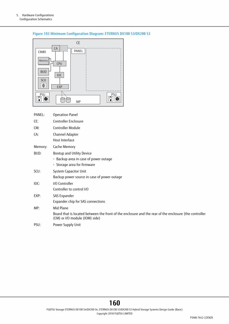
Figure 103 Minimum Configuration Diagram: ETERNUS DX100 S3/DX200 S3
CE
IOC
EXP
CPU
BUD
CACM#0
Memory
MP
SCU
PSU PSU
PANEL
PANEL: Operation Panel
CE: Controller Enclosure
CM: Controller Module
CA: Channel Adapter
Host Interface
Memory: Cache Memory
BUD: Bootup and Utility Device
• Backup area in case of power outage
• Storage area for firmware
SCU: System Capacitor Unit
Backup power source in case of power outage
IOC: I/O Controller
Controller to control I/O
EXP: SAS Expander
Expander chip for SAS connections
MP: Mid Plane
Board that is located between the front of the enclosure and the rear of the enclosure (the controller(CM) or I/O module (IOM) side)
PSU: Power Supply Unit
5. Hardware ConfigurationsConfiguration Schematics
160FUJITSU Storage ETERNUS DX100 S4/DX200 S4, ETERNUS DX100 S3/DX200 S3 Hybrid Storage Systems Design Guide (Basic)
Copyright 2018 FUJITSU LIMITEDP3AM-7642-22ENZ0
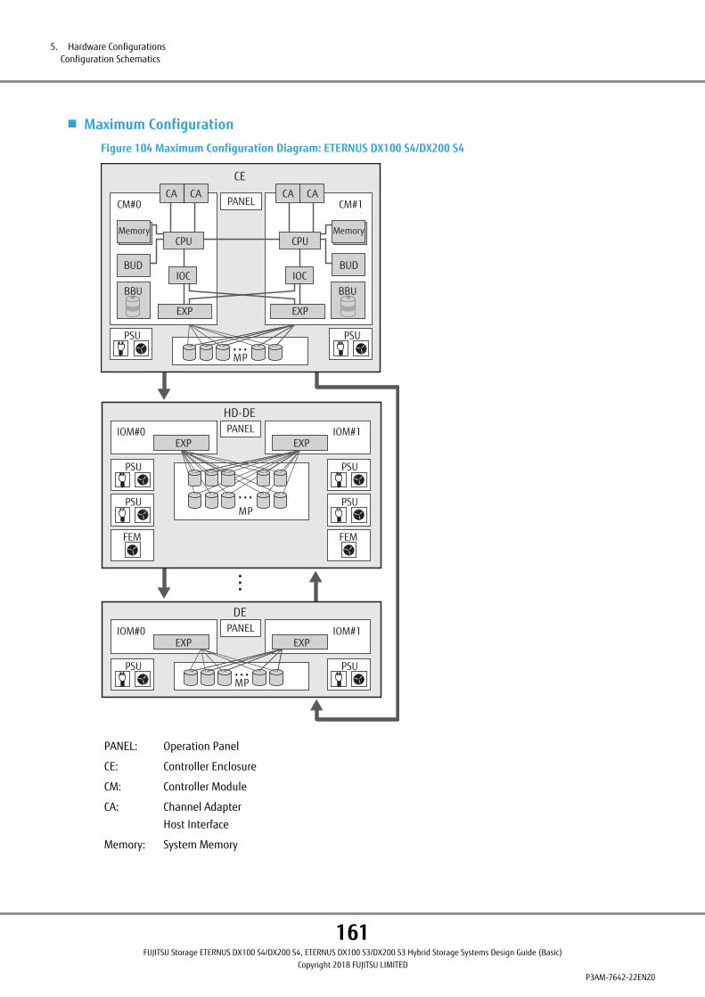
■ Maximum Configuration
Figure 104 Maximum Configuration Diagram: ETERNUS DX100 S4/DX200 S4
DE
IOM#0 IOM#1
PSU PSU
MP
PANEL
HD-DE
IOM#0 IOM#1
PSU PSU
PSU PSU
FEM FEM
MP
EXPPANEL
CE
IOC
CPU
BUD
CACM#0
CPUMemoryMemory
IOC
CM#1
MP
BUD
BBU BBU
PSU PSU
PANELCA CA CA
EXP
EXP EXP
EXP EXP
PANEL: Operation Panel
CE: Controller Enclosure
CM: Controller Module
CA: Channel Adapter
Host Interface
Memory: System Memory
5. Hardware ConfigurationsConfiguration Schematics
161FUJITSU Storage ETERNUS DX100 S4/DX200 S4, ETERNUS DX100 S3/DX200 S3 Hybrid Storage Systems Design Guide (Basic)
Copyright 2018 FUJITSU LIMITEDP3AM-7642-22ENZ0

BUD: Bootup and Utility Device
• Backup area in case of power outage
• Storage area for firmware
BBU: Battery Backup Unit
Backup power source in case of power outage
IOC: I/O Controller
Controller to control I/O
EXP: SAS Expander
Expander chip for SAS connections
DE: Drive Enclosure
IOM: I/O Module
Unit that controls I/O between controllers and drives
HD-DE: High-density Drive Enclosure
FEM: Fan Expander Module
Cooling fan module that is installed in a high-density drive enclosure
MP: Mid Plane
Board that is located between the front of the enclosure and the rear of the enclosure (the controller(CM) or I/O module (IOM) side)
PSU: Power Supply Unit
5. Hardware ConfigurationsConfiguration Schematics
162FUJITSU Storage ETERNUS DX100 S4/DX200 S4, ETERNUS DX100 S3/DX200 S3 Hybrid Storage Systems Design Guide (Basic)
Copyright 2018 FUJITSU LIMITEDP3AM-7642-22ENZ0

Figure 105 Maximum Configuration Diagram: ETERNUS DX100 S3/DX200 S3
DE
EXPIOM#0 IOM#1
PSU PSU
MP
EXPPANEL
HD-DE
EXPIOM#0 IOM#1
PSU PSU
PSU PSU
FEM FEM
MP
EXPPANEL
CE
IOC
EXP
CPU
BUD
CACACM#0
EXP
CPUMemoryMemory
CACA
IOC
CM#1
MP
BUD
SCU SCU
PSU PSU
PANEL
PANEL: Operation Panel
CE: Controller Enclosure
CM: Controller Module
CA: Channel Adapter
Host Interface
Memory: Cache Memory
BUD: Bootup and Utility Device
• Backup area in case of power outage
• Storage area for firmware
5. Hardware ConfigurationsConfiguration Schematics
163FUJITSU Storage ETERNUS DX100 S4/DX200 S4, ETERNUS DX100 S3/DX200 S3 Hybrid Storage Systems Design Guide (Basic)
Copyright 2018 FUJITSU LIMITEDP3AM-7642-22ENZ0

SCU: System Capacitor Unit
Backup power source in case of power outage
IOC: I/O Controller
Controller to control I/O
EXP: SAS Expander
Expander chip for SAS connections
DE: Drive Enclosure
IOM: I/O Module
Unit that controls I/O between controllers and drives
HD-DE: High-density Drive Enclosure
FEM: Fan Expander Module
Cooling fan module that is installed in a high-density drive enclosure
MP: Mid Plane
Board that is located between the front of the enclosure and the rear of the enclosure (the controller(CM) or I/O module (IOM) side)
PSU: Power Supply Unit
5. Hardware ConfigurationsConfiguration Schematics
164FUJITSU Storage ETERNUS DX100 S4/DX200 S4, ETERNUS DX100 S3/DX200 S3 Hybrid Storage Systems Design Guide (Basic)
Copyright 2018 FUJITSU LIMITEDP3AM-7642-22ENZ0

■ Enclosure Connection Path
In the ETERNUS DX, multiple paths are used to connect a controller enclosure (CE) to drive enclosures (DE).
A drive enclosure has two independent drive interface ports. Path redundancy is maintained by connecting thedrive enclosure to two controllers directly. This configuration allows operation to continue even if one of the con-nection paths fails.
Connect the controller enclosure to the drive enclosure as the following figures show.
Connection paths are not duplicated when only one controller is installed.
Figure 106 Enclosure Connection Path (When Only One Controller Is Installed)
DE #0x
CE
DE #01
DE #02
DE #0ADI
DI (IN)
DI (OUT)
DI (IN)
DI (OUT)
DI (IN)
DI (OUT)
DI (OUT): Drive interface (OUT) port
DI (IN): Drive interface (IN) port
Figure 107 Enclosure Connection Path (When Two Controllers Are Installed)
DE #0x
CE
DE #01
DE #02
DE #0ADI DI (IN)
DI (OUT)DI (IN)
DI (OUT) DI (IN)
DI (OUT)DI (IN)
DI (OUT) DI (IN)
DIDI (IN)
DI (OUT) DI (OUT)
DI (OUT): Drive interface (OUT) port
DI (IN): Drive interface (IN) port
5. Hardware ConfigurationsConfiguration Schematics
165FUJITSU Storage ETERNUS DX100 S4/DX200 S4, ETERNUS DX100 S3/DX200 S3 Hybrid Storage Systems Design Guide (Basic)
Copyright 2018 FUJITSU LIMITEDP3AM-7642-22ENZ0
Optional Product Installation ConditionsThis section provides the types and number of optional products and explains policies for optional product esti-mations.
Installation conditions for the following optional products are described in this section.
• Controller modules
• Memory Extension
• Host interfaces
• Unified License
• Drive enclosures
• I/O modules
• Drives
To install the following optional products, a specific firmware version may be required for the ETERNUS DX.
For details, refer to the "Firmware Release Information" section in "Overview" or refer to "Product List".
• ETERNUS DX100 S4/DX200 S4
- Host interfaces (FC 32Gbit/s)
• ETERNUS DX100 S3/DX200 S3
- Memory Extension
- Host interfaces (FC 16Gbit/s)
- Host interfaces (FC 8Gbit/s)
- Host interfaces (SAS 6Gbit/s)
- Host interfaces (iSCSI 10Gbit/s, 10GBASE-T)
- Unified kit
- Unified License
- High-density drive enclosures (12Gbit/s)
- Active optical cables
- Nearline SAS self-encrypting disks
- SSDs (12Gbit/s)
- Self encrypting SSDs
- Advanced Format disks
Controller ModuleThis section explains the installation conditions for controller modules.
■ Types of Controller Modules
The following types of controller are available; a controller that has no host interfaces and a controller that hashost interfaces.
5. Hardware ConfigurationsOptional Product Installation Conditions
166FUJITSU Storage ETERNUS DX100 S4/DX200 S4, ETERNUS DX100 S3/DX200 S3 Hybrid Storage Systems Design Guide (Basic)
Copyright 2018 FUJITSU LIMITEDP3AM-7642-22ENZ0
■ Number of Installable Controller Modules
Up to two controller modules can be installed in a controller enclosure.
Memory ExtensionThis section explains the installation conditions for the Memory Extension.
When only one controller is installed in the controller enclosure, Memory Extension cannot be installed.
● ETERNUS DX100 S4
Memory Extension is required to use the Unified License.
This option cannot be installed if the Unified License (NAS function) is not used.
Only one Memory Extension can be installed for each ETERNUS DX.
The Memory Extension is installed as standard in the controller module for Unified models.
● ETERNUS DX200 S4
Memory Extension is required to use the Deduplication/Compression function or the Unified License.
This option cannot be installed if the Deduplication/Compression function or the Unified License (NAS function)is not used.
Only one Memory Extension can be installed for each ETERNUS DX.
The Memory Extension is installed as standard in the controller module for standard models and the controllermodule for Unified models.
● ETERNUS DX100 S3
Memory Extension is required to use the Unified License.
This option cannot be installed if the Unified kit/Unified License (NAS function) is not used.
Only one Memory Extension can be installed for each ETERNUS DX.
Memory Extension (ETFMCC-L / ETDMCCU-L) can be installed to expand the NAS function if a Unified kit(ETFLN1U / ETFLN1U-L / ETDLN1U / ETDLN1U-L) or Memory Extension (ETFMCA / ETFMCA-L / ETDMCAU / ETDM-CAU-L) is already installed.
● ETERNUS DX200 S3
Memory Extension is required to use the Deduplication/Compression function or the Unified License.
Memory Extension cannot be installed if the Deduplication/Compression function or the Unified kit/Unified Li-cense (NAS function) is not used.
Only one Memory Extension can be installed for each ETERNUS DX.
Memory Extension (ETFMCB-L / ETDMCBU-L) can be installed to expand the NAS function if a Unified kit(ETFLN2U / ETFLN2U-L / ETDLN2U / ETDLN2U-L) is already installed.
5. Hardware ConfigurationsOptional Product Installation Conditions
167FUJITSU Storage ETERNUS DX100 S4/DX200 S4, ETERNUS DX100 S3/DX200 S3 Hybrid Storage Systems Design Guide (Basic)
Copyright 2018 FUJITSU LIMITEDP3AM-7642-22ENZ0
Host InterfacesThis section explains the installation conditions for host interfaces.
■ Types of Host Interfaces
The following types are available SAN or NAS connections.
● ETERNUS DX100 S4/DX200 S4
• SAN connection
- FC 32Gbit/s
- FC 16Gbit/s
- FC 8Gbit/s
- iSCSI 10Gbit/s (10GBASE-SR (*1)/10GBASE-CR)
- iSCSI 10Gbit/s (10GBASE-T)
- iSCSI 1Gbit/s (1000BASE-T)
- SAS 12Gbit/s
• NAS connection
- Ethernet 10Gbit/s (*1)
- Ethernet 1Gbit/s
*1: The SFP+ modules are not installed. The SFP+ modules are required to connect the FC cables.
● ETERNUS DX100 S3/DX200 S3
• SAN connection
- FC 16Gbit/s
- FC 8Gbit/s
- iSCSI 10Gbit/s (10GBASE-SR)
- iSCSI 10Gbit/s (10GBASE-CR)
- iSCSI 10Gbit/s (10GBASE-T)
- iSCSI 1Gbit/s (1000BASE-T)
- FCoE 10Gbit/s
- SAS 6Gbit/s
• NAS Connection
- Ethernet 10Gbit/s
- Ethernet 1Gbit/s
The features of each host interface are described below.
● FC
Fibre Channel (FC) enables high speed data transfer over long distances by using optical fibers and coaxial ca-bles. FC is used for database servers where enhanced scalability and high performance are required.
5. Hardware ConfigurationsOptional Product Installation Conditions
168FUJITSU Storage ETERNUS DX100 S4/DX200 S4, ETERNUS DX100 S3/DX200 S3 Hybrid Storage Systems Design Guide (Basic)
Copyright 2018 FUJITSU LIMITEDP3AM-7642-22ENZ0

● iSCSI
iSCSI is a communication protocol that transfers SCSI commands by encapsulating them in IP packets over Ether-net.
Since iSCSI can be installed at a lower cost and the network configuration is easier to change than FC, iSCSI iscommonly used by divisions of large companies and by small and medium-sized companies where scalabilityand cost-effectiveness are valued over performance.
● FCoE
Since Fibre Channel over Ethernet (FCoE) encapsulates FC frames and transfers them over Ethernet, a LAN envi-ronment and an FC-SAN environment can be integrated. When there are networks for multiple I/O interfaces(e.g. in a data center), the networks can be integrated and managed.
● SAS
Serial Attached SCSI (SAS) enables high speed data transfers by upgrading existing reliable SCSI connectionstandards to allow serial transfers. SAS is commonly used for small-sized systems where performance and cost-effectiveness are valued over scalability.
● Ethernet
Ethernet is a NAS connection interface. An Ethernet network can be accessed as a file server from multiple con-nected clients with different operating systems, for the easy sharing of data. The ETERNUS DX has an internal filesystem for connection to existing LAN, allowing Ethernet to be installed relatively easily. However, load on thenetwork will increase, and therefore Ethernet is not suitable for applications that require high transfer rates.
A Unified kit is required to install Ethernet host interface. Registering the Unified kit license to the storage sys-tem enables the NAS function.
■ Number of Installable Host Interfaces
When one controller is installed, two host interfaces for base and expansion configurations (two host interfacesper storage system) can be installed. When two controllers are installed, two host interfaces for base and expan-sion configurations (four host interfaces per storage system) can be installed.
Different types of host interfaces can exist together in the same ETERNUS DX.
Unified LicenseInstalling the Unified License requires the Memory Extension and an Ethernet host interface, or a controllermodule that is equipped with an Ethernet host interface.
The Memory Extension is installed as standard in the ETERNUS DX100 S4/DX200 S4 controller module for Unifiedmodels and the ETERNUS DX200 S4 controller module for standard models.
The Memory Extension must be ordered if the ETERNUS DX100 S4 controller module for SAN connections, theETERNUS DX200 S4 controller module for economy models, or the ETERNUS DX100 S3/DX200 S3 is used.
Unified kit/Unified License cannot be installed if the Deduplication/Compression function is used.
5. Hardware ConfigurationsOptional Product Installation Conditions
169FUJITSU Storage ETERNUS DX100 S4/DX200 S4, ETERNUS DX100 S3/DX200 S3 Hybrid Storage Systems Design Guide (Basic)
Copyright 2018 FUJITSU LIMITEDP3AM-7642-22ENZ0
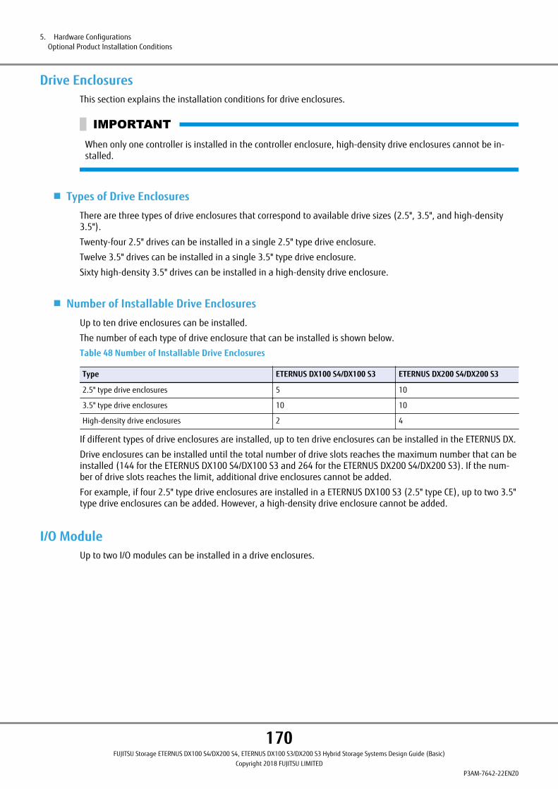
Drive EnclosuresThis section explains the installation conditions for drive enclosures.
When only one controller is installed in the controller enclosure, high-density drive enclosures cannot be in-stalled.
■ Types of Drive Enclosures
There are three types of drive enclosures that correspond to available drive sizes (2.5", 3.5", and high-density3.5").
Twenty-four 2.5" drives can be installed in a single 2.5" type drive enclosure.
Twelve 3.5" drives can be installed in a single 3.5" type drive enclosure.
Sixty high-density 3.5" drives can be installed in a high-density drive enclosure.
■ Number of Installable Drive Enclosures
Up to ten drive enclosures can be installed.
The number of each type of drive enclosure that can be installed is shown below.
Table 48 Number of Installable Drive Enclosures
Type ETERNUS DX100 S4/DX100 S3 ETERNUS DX200 S4/DX200 S3
2.5" type drive enclosures 5 10
3.5" type drive enclosures 10 10
High-density drive enclosures 2 4
If different types of drive enclosures are installed, up to ten drive enclosures can be installed in the ETERNUS DX.
Drive enclosures can be installed until the total number of drive slots reaches the maximum number that can beinstalled (144 for the ETERNUS DX100 S4/DX100 S3 and 264 for the ETERNUS DX200 S4/DX200 S3). If the num-ber of drive slots reaches the limit, additional drive enclosures cannot be added.
For example, if four 2.5" type drive enclosures are installed in a ETERNUS DX100 S3 (2.5" type CE), up to two 3.5"type drive enclosures can be added. However, a high-density drive enclosure cannot be added.
I/O ModuleUp to two I/O modules can be installed in a drive enclosures.
5. Hardware ConfigurationsOptional Product Installation Conditions
170FUJITSU Storage ETERNUS DX100 S4/DX200 S4, ETERNUS DX100 S3/DX200 S3 Hybrid Storage Systems Design Guide (Basic)
Copyright 2018 FUJITSU LIMITEDP3AM-7642-22ENZ0

DrivesThis section explains the installation conditions for drives.
■ Types of Drives
The ETERNUS DX supports the latest drives that have the high-speed SAS (Max. 12Gbit/s) interface.
The following drive types can be installed in the ETERNUS DX. Some drive types have a data encryption function.
• SAS disks
• Nearline SAS disks
• SSDs
2.5" and 3.5" drive sizes are available.
Since 2.5" drives are lighter and require less power than 3.5" drives, the total weight and power consumptionwhen 2.5" drives are installed is less than when the same number of 3.5" drives is installed.
When the data I/O count is compared based on the number of drives in an enclosure (2.5" drives: 24, 3.5" drives:12), the Input Output Per Second (IOPS) performance for each enclosure in a 2.5" drive configuration is superiorto a 3.5" drive configuration since more 2.5" drives can be installed in an enclosure than 3.5" drives.
● SAS Disks
SAS disks are high-performance and high-reliability disks. They are used to store high performance databasesand other frequently accessed data.
• The following disks are Advanced Format (512e) disks.
- 1.8TB SAS disks
- 2.4TB SAS disks
- 2.5" SAS self encrypting disks (2.4TB)
• When using Advanced Format (512e) disks, make sure that Advanced Format (512e) is supported by theserver OS and the applications. If the server OS and applications do not support Advanced Format (512e),random write performance may be reduced.
● Nearline SAS Disks
Nearline SAS disks are high capacity cost effective disks for data backup and archive use. Nearline SAS disks canstore information that requires a low access rate at a reasonable speed more cost effectively than SAS disks.
5. Hardware ConfigurationsOptional Product Installation Conditions
171FUJITSU Storage ETERNUS DX100 S4/DX200 S4, ETERNUS DX100 S3/DX200 S3 Hybrid Storage Systems Design Guide (Basic)
Copyright 2018 FUJITSU LIMITEDP3AM-7642-22ENZ0

• Nearline SAS disks are used to store data that does not need the access performance of SAS disks. They arefar more cost effective than SAS disks. It is recommended that SAS disks be used for data that is constantlyaccessed or when high performance/reliability is required.
• If the ambient temperature exceeds the operating environment conditions, Nearline SAS disk performancemay be reduced.
• Nearline SAS disks can be used as Advanced Copy destinations and for the storage of archived data.
• When Nearline SAS disks are used as an Advanced Copy destination, delayed access responses and slowercopy speeds may be noticed, depending on the amount of I/O and the number of copy sessions.
• The following disks are Advanced Format (512e) disks.
- 2.5" Nearline SAS disks (2TB)
- 3.5" Nearline SAS disks (6TB)
- 3.5" Nearline SAS disks (8TB)
- 3.5" Nearline SAS disks (10TB)
- 3.5" Nearline SAS disks (12TB)
- 3.5" Nearline SAS self encrypting disks (8TB)
- 3.5" Nearline SAS self encrypting disks (12TB)
• When using Advanced Format (512e) disks, make sure that Advanced Format (512e) is supported by theserver OS and the applications. If the server OS and applications do not support Advanced Format (512e),random write performance may be reduced.
• For details on the RAID levels that can be configured with Nearline SAS disks that have 6TB or more, refer to"Supported RAID" (page 16).
● SSDs
SSDs are reliable drives with high performance. SSDs are used to store high performance databases and otherfrequently accessed data.
Flash memory as a storage media provides better random access performance than disks such as SAS disks andNearline SAS disks. Containing no motors or other moving parts, they are highly resistant to impact.
The ETERNUS DX supports SSDs that have a high level wear leveling function and sufficient reserved space. Notethat if the expected total write capacity is exceeded, the frequency of errors gradually increases, which may leadto a reduction in the write performance. The ETERNUS DX has a function that shows the remaining capacity as apercentage (health) in proportion to the expected total write capacity.
The number of rewrites may exceed the limit within the product warranty period if SSDs are used in a RAID1configuration that has a high I/O access load. Using a RAID1+0, RAID5, RAID5+0, or RAID6 configuration is rec-ommended.
The following types of SSDs are supported in the ETERNUS DX.
• MLC SSDs (with a 12Gbit/s or a 6Gbit/s interface speed) that are compatible with Extreme Cache Pools
• Value SSDs (with a 12Gbit/s interface speed) that are incompatible with Extreme Cache Pools
Value SSDs are available at a lower cost per capacity than conventional SSDs by optimizing the guaranteed writeendurance and the reserved space.
When random access (especially with write access) continues for several hours, the performance of Value SSDsmay be reduced compared with MLC SSDs that support Extreme Cache Pool.
Note that the product's actual capacity of a Value SSD differs from the capacity that is displayed in ETERNUS WebGUI and ETERNUS CLI. For example, 2.00TB is displayed for a 1.92TB Value SSD.
5. Hardware ConfigurationsOptional Product Installation Conditions
172FUJITSU Storage ETERNUS DX100 S4/DX200 S4, ETERNUS DX100 S3/DX200 S3 Hybrid Storage Systems Design Guide (Basic)
Copyright 2018 FUJITSU LIMITEDP3AM-7642-22ENZ0
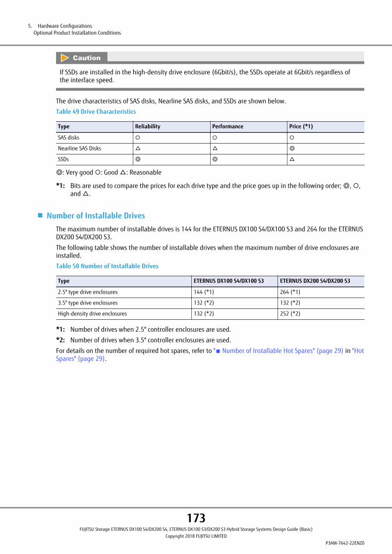
If SSDs are installed in the high-density drive enclosure (6Gbit/s), the SSDs operate at 6Gbit/s regardless ofthe interface speed.
The drive characteristics of SAS disks, Nearline SAS disks, and SSDs are shown below.
Table 49 Drive Characteristics
Type Reliability Performance Price (*1)
SAS disks ¡ ¡ ¡
Nearline SAS Disks △ △ ◎
SSDs ◎ ◎ △
◎: Very good ¡: Good △: Reasonable
*1: Bits are used to compare the prices for each drive type and the price goes up in the following order; ◎, ¡,and △.
■ Number of Installable Drives
The maximum number of installable drives is 144 for the ETERNUS DX100 S4/DX100 S3 and 264 for the ETERNUSDX200 S4/DX200 S3.
The following table shows the number of installable drives when the maximum number of drive enclosures areinstalled.
Table 50 Number of Installable Drives
Type ETERNUS DX100 S4/DX100 S3 ETERNUS DX200 S4/DX200 S3
2.5" type drive enclosures 144 (*1) 264 (*1)
3.5" type drive enclosures 132 (*2) 132 (*2)
High-density drive enclosures 132 (*2) 252 (*2)
*1: Number of drives when 2.5" controller enclosures are used.
*2: Number of drives when 3.5" controller enclosures are used.
For details on the number of required hot spares, refer to "■ Number of Installable Hot Spares" (page 29) in "HotSpares" (page 29).
5. Hardware ConfigurationsOptional Product Installation Conditions
173FUJITSU Storage ETERNUS DX100 S4/DX200 S4, ETERNUS DX100 S3/DX200 S3 Hybrid Storage Systems Design Guide (Basic)
Copyright 2018 FUJITSU LIMITEDP3AM-7642-22ENZ0
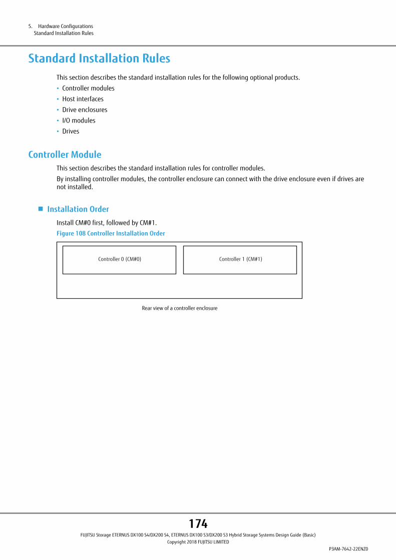
Standard Installation RulesThis section describes the standard installation rules for the following optional products.
• Controller modules
• Host interfaces
• Drive enclosures
• I/O modules
• Drives
Controller ModuleThis section describes the standard installation rules for controller modules.
By installing controller modules, the controller enclosure can connect with the drive enclosure even if drives arenot installed.
■ Installation Order
Install CM#0 first, followed by CM#1.
Figure 108 Controller Installation Order
Rear view of a controller enclosure
Controller 0 (CM#0) Controller 1 (CM#1)
5. Hardware ConfigurationsStandard Installation Rules
174FUJITSU Storage ETERNUS DX100 S4/DX200 S4, ETERNUS DX100 S3/DX200 S3 Hybrid Storage Systems Design Guide (Basic)
Copyright 2018 FUJITSU LIMITEDP3AM-7642-22ENZ0

Host InterfaceThis section describes the standard installation rules for host interfaces.
■ When Only One Controller Is Installed
Install CA#0 first, and then install CA#1.
Figure 109 Installation Diagram for Host Interfaces (When Only One Controller Is Installed)
Port
#0
Port
#1
CA#1
Port
#0
Port
#1
CA#0
Controller 0 (CM#0)Expansion
Rear view of a controller enclosure
■ When Two Controllers Are Installed
● Installation Order for the ETERNUS DX100 S4/DX100 S3
Install the host interfaces in CA#0 first, and then install CA#1.
The configuration is the same for Controller 0 (CM#0) and Controller 1 (CM#1).
Note that the positions of CA#0 and CA#1 depend on the controller type.
If an FC 16Gbit/s or FC 8Gbit/s is installed in the controller as the standard host interface, CA#0 is located on theright side of the controller.
Figure 110 Host Interface Installation Diagram 1 (When Two Controllers Are Installed in the ETERNUS DX100 S4/DX100 S3)
Controller 0 (CM#0) Controller 1 (CM#1)
Port
#0
Port
#1
CA#1
Port
#0
Port
#1
CA#0
Port
#0
Port
#1
CA#1
Port
#0
Port
#1
CA#0
Expansion Expansion
Rear view of a controller enclosure
5. Hardware ConfigurationsStandard Installation Rules
175FUJITSU Storage ETERNUS DX100 S4/DX200 S4, ETERNUS DX100 S3/DX200 S3 Hybrid Storage Systems Design Guide (Basic)
Copyright 2018 FUJITSU LIMITEDP3AM-7642-22ENZ0

If an FC 16Gbit/s or FC 8Gbit/s that is sold separately from the controller is installed as the standard host inter-face or if an FC 32Gbit/s, an iSCSI, an SAS, an FCoE, or an Ethernet is installed in the controller as the standardhost interface, CA#0 is located on the left side of the controller.
Figure 111 Host Interface Installation Diagram 2 (When Two Controllers Are Installed in the ETERNUS DX100 S4/DX100 S3)
Controller 0 (CM#0) Controller 1 (CM#1)
Port
#0
Port
#1
CA#1
Port
#0
Port
#1
CA#0
Port
#0
Port
#1
CA#1
Port
#0
Port
#1
CA#0
Expansion Expansion
Rear view of the controller enclosure
● Installation Order for the ETERNUS DX200 S4/DX200 S3
Install the host interfaces in CA#0 first, and then install CA#1.
The configuration is the same for Controller 0 (CM#0) and Controller 1 (CM#1).
Figure 112 Host Interface Installation Diagram (When Two Controllers Are Installed in the ETERNUS DX200 S4/DX200 S3)
Controller 0 (CM#0) Controller 1 (CM#1)
Port
#0
Port
#1
CA#1
Port
#0
Port
#1
CA#0
Port
#0
Port
#1
CA#1
Port
#0
Port
#1
CA#0
Expansion Expansion
Rear view of the controller enclosure
5. Hardware ConfigurationsStandard Installation Rules
176FUJITSU Storage ETERNUS DX100 S4/DX200 S4, ETERNUS DX100 S3/DX200 S3 Hybrid Storage Systems Design Guide (Basic)
Copyright 2018 FUJITSU LIMITEDP3AM-7642-22ENZ0

Drive EnclosureThis section describes the installation order for drive enclosures.
2.5" type, 3.5" type, and high-density drive enclosures can be installed together in the ETERNUS DX.
Drive enclosures can connect with other enclosures even if drives are not installed.
The installation priority order for drive enclosures varies depending on the controller enclosure type.
■ 2.5" Type Controller Enclosure
1 High-density drive enclosures (12Gbit/s)
2 High-density drive enclosures (6Gbit/s)
3 2.5" type drive enclosures
4 3.5" type drive enclosures
■ 3.5" Type Controller Enclosure
1 High-density drive enclosures (12Gbit/s)
2 High-density drive enclosures (6Gbit/s)
3 3.5" type drive enclosures
4 2.5" type drive enclosures
Drive enclosures are installed above the controller enclosure according to the priority order.
I/O ModuleThis section describes the standard installation rules for I/O modules.
By installing I/O modules, the drive enclosure can connect with other enclosures even if drives are not installed.
■ Installation Order
Install IOM#0 first, and then install IOM#1.
Figure 113 I/O Module Installation Order
Rear view of a drive enclosure
I/O module 0 (IOM#0) I/O module 1 (IOM#1)
5. Hardware ConfigurationsStandard Installation Rules
177FUJITSU Storage ETERNUS DX100 S4/DX200 S4, ETERNUS DX100 S3/DX200 S3 Hybrid Storage Systems Design Guide (Basic)
Copyright 2018 FUJITSU LIMITEDP3AM-7642-22ENZ0

DriveThis section explains the installation rules for drives.
The supported drives vary between the ETERNUS DX100 S4/DX200 S4 and the ETERNUS DX100 S3/DX200 S3. Fordetails about drives, refer to "Overview" of the currently used storage systems.
■ Drives for High-Density Drive Enclosures
The installation priority order for drives in high-density drive enclosures is shown below.
1 3.5" SSDs for high-density drive enclosures (1.6TB)
2 3.5" SSDs for high-density drive enclosures (1.92TB)
3 3.5" SSDs for high-density drive enclosures (3.84TB)
4 3.5" SAS disks for high-density drive enclosures (1.2TB/10krpm)
5 3.5" Nearline SAS disks for high-density drive enclosures (2TB/7.2krpm)
6 3.5" Nearline SAS disks for high-density drive enclosures (3TB/7.2krpm)
7 3.5" Nearline SAS disks for high-density drive enclosures (4TB/7.2krpm)
8 3.5" Nearline SAS disks for high-density drive enclosures (6TB/7.2krpm)
9 3.5" Nearline SAS disks for high-density drive enclosures (8TB/7.2krpm)
10 3.5" Nearline SAS disks for high-density drive enclosures (10TB/7.2krpm)
11 3.5" Nearline SAS disks for high-density drive enclosures (12TB/7.2krpm)
12 3.5" Nearline SAS self encrypting disks for high-density drive enclosures (4TB/7.2krpm)
13 3.5" Nearline SAS self encrypting disks for high-density drive enclosures (8TB/7.2krpm)
14 3.5" Nearline SAS self encrypting disks for high-density drive enclosures (12TB/7.2krpm)
5. Hardware ConfigurationsStandard Installation Rules
178FUJITSU Storage ETERNUS DX100 S4/DX200 S4, ETERNUS DX100 S3/DX200 S3 Hybrid Storage Systems Design Guide (Basic)
Copyright 2018 FUJITSU LIMITEDP3AM-7642-22ENZ0
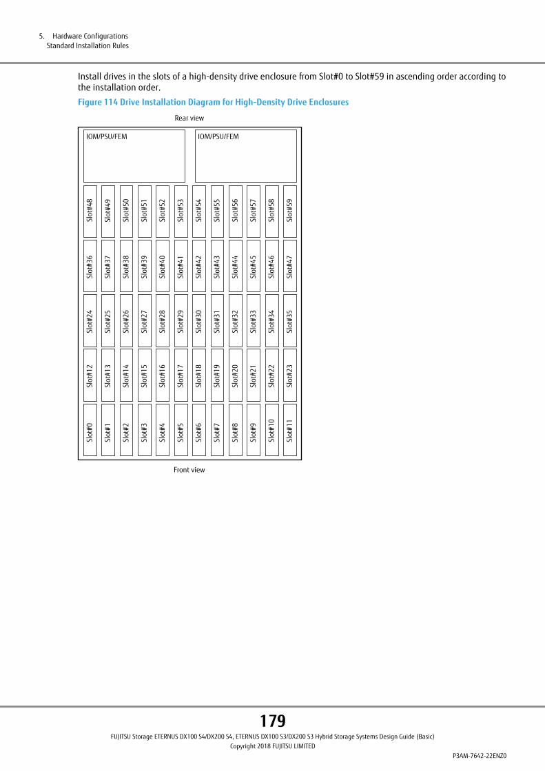
Install drives in the slots of a high-density drive enclosure from Slot#0 to Slot#59 in ascending order according tothe installation order.
Figure 114 Drive Installation Diagram for High-Density Drive Enclosures
IOM/PSU/FEM
Slot
#48
Slot
#57
Slot
#56
Slot
#55
Slot
#54
Slot
#53
Slot
#52
Slot
#51
Slot
#50
Slot
#49
Slot
#59
Slot
#58
Slot
#36
Slot
#45
Slot
#44
Slot
#43
Slot
#42
Slot
#41
Slot
#40
Slot
#39
Slot
#38
Slot
#37
Slot
#47
Slot
#46
Slot
#24
Slot
#33
Slot
#32
Slot
#31
Slot
#30
Slot
#29
Slot
#28
Slot
#27
Slot
#26
Slot
#25
Slot
#35
Slot
#34
Slot
#12
Slot
#21
Slot
#20
Slot
#19
Slot
#18
Slot
#17
Slot
#16
Slot
#15
Slot
#14
Slot
#13
Slot
#23
Slot
#22
Slot
#0
Slot
#9
Slot
#8
Slot
#7
Slot
#6
Slot
#5
Slot
#4
Slot
#3
Slot
#2
Slot
#1
Slot
#11
Slot
#10
IOM/PSU/FEM
Front view
Rear view
5. Hardware ConfigurationsStandard Installation Rules
179FUJITSU Storage ETERNUS DX100 S4/DX200 S4, ETERNUS DX100 S3/DX200 S3 Hybrid Storage Systems Design Guide (Basic)
Copyright 2018 FUJITSU LIMITEDP3AM-7642-22ENZ0
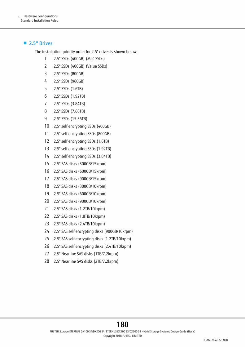
■ 2.5" Drives
The installation priority order for 2.5" drives is shown below.
1 2.5" SSDs (400GB) (MLC SSDs)
2 2.5" SSDs (400GB) (Value SSDs)
3 2.5" SSDs (800GB)
4 2.5" SSDs (960GB)
5 2.5" SSDs (1.6TB)
6 2.5" SSDs (1.92TB)
7 2.5" SSDs (3.84TB)
8 2.5" SSDs (7.68TB)
9 2.5" SSDs (15.36TB)
10 2.5" self encrypting SSDs (400GB)
11 2.5" self encrypting SSDs (800GB)
12 2.5" self encrypting SSDs (1.6TB)
13 2.5" self encrypting SSDs (1.92TB)
14 2.5" self encrypting SSDs (3.84TB)
15 2.5" SAS disks (300GB/15krpm)
16 2.5" SAS disks (600GB/15krpm)
17 2.5" SAS disks (900GB/15krpm)
18 2.5" SAS disks (300GB/10krpm)
19 2.5" SAS disks (600GB/10krpm)
20 2.5" SAS disks (900GB/10krpm)
21 2.5" SAS disks (1.2TB/10krpm)
22 2.5" SAS disks (1.8TB/10krpm)
23 2.5" SAS disks (2.4TB/10krpm)
24 2.5" SAS self encrypting disks (900GB/10krpm)
25 2.5" SAS self encrypting disks (1.2TB/10krpm)
26 2.5" SAS self encrypting disks (2.4TB/10krpm)
27 2.5" Nearline SAS disks (1TB/7.2krpm)
28 2.5" Nearline SAS disks (2TB/7.2krpm)
5. Hardware ConfigurationsStandard Installation Rules
180FUJITSU Storage ETERNUS DX100 S4/DX200 S4, ETERNUS DX100 S3/DX200 S3 Hybrid Storage Systems Design Guide (Basic)
Copyright 2018 FUJITSU LIMITEDP3AM-7642-22ENZ0

According to the installation order, install drives in the slots of a controller enclosure from Slot#0 to Slot#23 inascending order. Then, install drives in the slots of a drive enclosure from Slot#0 to Slot#23 in ascending order.
Figure 115 Installation Diagram for 2.5" Drives
Slot
#8
Slot
#9
Slot
#10
Slot
#11
Slot
#12
Slot
#13
Slot
#14
Slot
#15
Slot
#0
Slot
#1
Slot
#2
Slot
#3
Slot
#4
Slot
#5
Slot
#6
Slot
#7
Slot
#16
Slot
#17
Slot
#18
Slot
#19
Slot
#20
Slot
#21
Slot
#22
Slot
#23
5. Hardware ConfigurationsStandard Installation Rules
181FUJITSU Storage ETERNUS DX100 S4/DX200 S4, ETERNUS DX100 S3/DX200 S3 Hybrid Storage Systems Design Guide (Basic)
Copyright 2018 FUJITSU LIMITEDP3AM-7642-22ENZ0
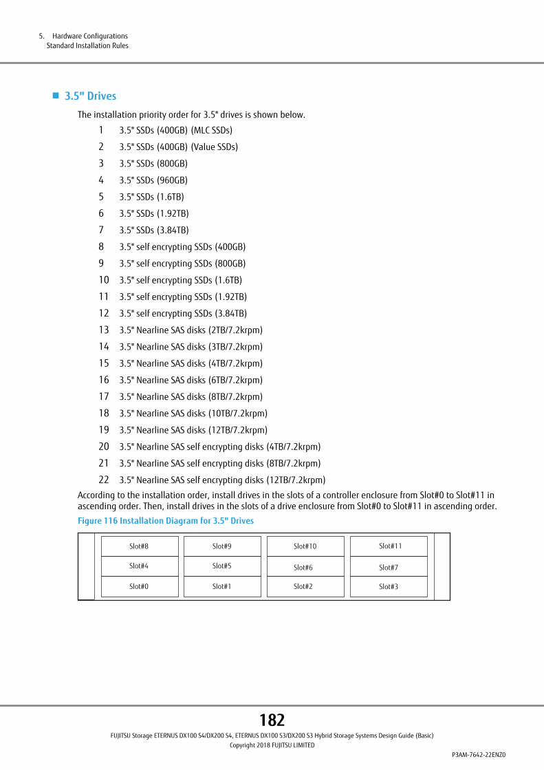
■ 3.5" Drives
The installation priority order for 3.5" drives is shown below.
1 3.5" SSDs (400GB) (MLC SSDs)
2 3.5" SSDs (400GB) (Value SSDs)
3 3.5" SSDs (800GB)
4 3.5" SSDs (960GB)
5 3.5" SSDs (1.6TB)
6 3.5" SSDs (1.92TB)
7 3.5" SSDs (3.84TB)
8 3.5" self encrypting SSDs (400GB)
9 3.5" self encrypting SSDs (800GB)
10 3.5" self encrypting SSDs (1.6TB)
11 3.5" self encrypting SSDs (1.92TB)
12 3.5" self encrypting SSDs (3.84TB)
13 3.5" Nearline SAS disks (2TB/7.2krpm)
14 3.5" Nearline SAS disks (3TB/7.2krpm)
15 3.5" Nearline SAS disks (4TB/7.2krpm)
16 3.5" Nearline SAS disks (6TB/7.2krpm)
17 3.5" Nearline SAS disks (8TB/7.2krpm)
18 3.5" Nearline SAS disks (10TB/7.2krpm)
19 3.5" Nearline SAS disks (12TB/7.2krpm)
20 3.5" Nearline SAS self encrypting disks (4TB/7.2krpm)
21 3.5" Nearline SAS self encrypting disks (8TB/7.2krpm)
22 3.5" Nearline SAS self encrypting disks (12TB/7.2krpm)
According to the installation order, install drives in the slots of a controller enclosure from Slot#0 to Slot#11 inascending order. Then, install drives in the slots of a drive enclosure from Slot#0 to Slot#11 in ascending order.
Figure 116 Installation Diagram for 3.5" Drives
Slot#0
Slot#4
Slot#8
Slot#1
Slot#5
Slot#9
Slot#2
Slot#6
Slot#10
Slot#3
Slot#7
Slot#11
5. Hardware ConfigurationsStandard Installation Rules
182FUJITSU Storage ETERNUS DX100 S4/DX200 S4, ETERNUS DX100 S3/DX200 S3 Hybrid Storage Systems Design Guide (Basic)
Copyright 2018 FUJITSU LIMITEDP3AM-7642-22ENZ0

Recommended RAID Group ConfigurationsNo restrictions on the installation location of drives apply if the same types of drives are used to create RAIDgroups.
To improve reliability, the installation location of drives that configure a RAID group must be considered.
Data reliability when enclosures fail can be improved by selecting configuration drives that are distributed to alarger number of enclosures when a RAID group is created.
For details on the recommended number of drives that configure a RAID group, refer to "RAID Group" (page 24).
■ Mirroring Configuration
RAID1+0(4D+4M) is used in the following examples to explain how drives are installed to configure a mirroringRAID level.
The drive number is determined by the DE-ID of the enclosure and the slot number in which the drive is instal-led. Starting from the smallest drive number in the configuration, half of the drives are allocated into one groupand the remaining drives are allocated into the other group. Each drive in the different groups are paired formirroring.
Example 1: All drives are installed in a single enclosure
Figure 117 Drive Combination 1
DE#00
Mirroring
A B C D A' B' C' D'
Example 2: Paired drives are installed in two different enclosures
Figure 118 Drive Combination 2
DE#00
Mirroring
A B C D
DE#01
A' B' C' D'
5. Hardware ConfigurationsRecommended RAID Group Configurations
183FUJITSU Storage ETERNUS DX100 S4/DX200 S4, ETERNUS DX100 S3/DX200 S3 Hybrid Storage Systems Design Guide (Basic)
Copyright 2018 FUJITSU LIMITEDP3AM-7642-22ENZ0

Example 3: Paired drives are installed in three different enclosures
Figure 119 Drive Combination 3
DE#02
B’ C’
DE#01
Mirroring
C A’
DE#00
Mirroring
A B
■ Double Striping Configuration with Distributed Parity
RAID5+0(2D+1P) ´2 is used in the following examples to explain how to install drives that are configured fordouble striping with distributed parity.
The drive number is determined by the DE-ID of the enclosure and the slot number in which the drive is instal-led. Drives are divided into two redundant set groups in ascending order of drive numbers.
Example 4: Drives are installed in two different enclosures
Figure 120 Drive Combination 4
DE#00
A D B
DE#01
E C F
:Redundancy Group 1
:Redundancy Group 2
5. Hardware ConfigurationsRecommended RAID Group Configurations
184FUJITSU Storage ETERNUS DX100 S4/DX200 S4, ETERNUS DX100 S3/DX200 S3 Hybrid Storage Systems Design Guide (Basic)
Copyright 2018 FUJITSU LIMITEDP3AM-7642-22ENZ0

Example 5: Drives are installed in three different enclosures
Figure 121 Drive Combination 5
DE#02
FC
DE#01
B E
DE#00
A D
:Redundancy Group 1
:Redundancy Group 2
5. Hardware ConfigurationsRecommended RAID Group Configurations
185FUJITSU Storage ETERNUS DX100 S4/DX200 S4, ETERNUS DX100 S3/DX200 S3 Hybrid Storage Systems Design Guide (Basic)
Copyright 2018 FUJITSU LIMITEDP3AM-7642-22ENZ0
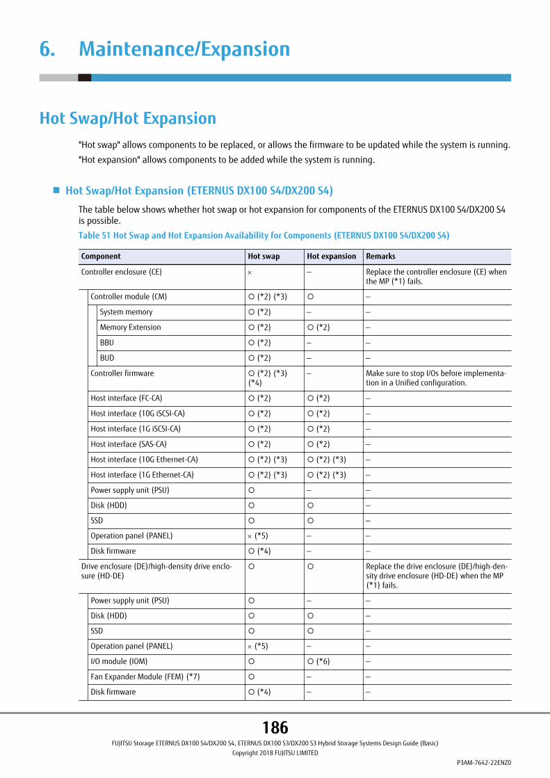
6. Maintenance/Expansion
Hot Swap/Hot Expansion"Hot swap" allows components to be replaced, or allows the firmware to be updated while the system is running.
"Hot expansion" allows components to be added while the system is running.
■ Hot Swap/Hot Expansion (ETERNUS DX100 S4/DX200 S4)
The table below shows whether hot swap or hot expansion for components of the ETERNUS DX100 S4/DX200 S4is possible.
Table 51 Hot Swap and Hot Expansion Availability for Components (ETERNUS DX100 S4/DX200 S4)
Component Hot swap Hot expansion Remarks
Controller enclosure (CE) ´ — Replace the controller enclosure (CE) whenthe MP (*1) fails.
Controller module (CM) ¡ (*2) (*3) ¡ —
System memory ¡ (*2) — —
Memory Extension ¡ (*2) ¡ (*2) —
BBU ¡ (*2) — —
BUD ¡ (*2) — —
Controller firmware ¡ (*2) (*3)(*4)
— Make sure to stop I/Os before implementa-tion in a Unified configuration.
Host interface (FC-CA) ¡ (*2) ¡ (*2) —
Host interface (10G iSCSI-CA) ¡ (*2) ¡ (*2) —
Host interface (1G iSCSI-CA) ¡ (*2) ¡ (*2) —
Host interface (SAS-CA) ¡ (*2) ¡ (*2) —
Host interface (10G Ethernet-CA) ¡ (*2) (*3) ¡ (*2) (*3) —
Host interface (1G Ethernet-CA) ¡ (*2) (*3) ¡ (*2) (*3) —
Power supply unit (PSU) ¡ — —
Disk (HDD) ¡ ¡ —
SSD ¡ ¡ —
Operation panel (PANEL) ´ (*5) — —
Disk firmware ¡ (*4) — —
Drive enclosure (DE)/high-density drive enclo-sure (HD-DE)
¡ ¡ Replace the drive enclosure (DE)/high-den-sity drive enclosure (HD-DE) when the MP(*1) fails.
Power supply unit (PSU) ¡ — —
Disk (HDD) ¡ ¡ —
SSD ¡ ¡ —
Operation panel (PANEL) ´ (*5) — —
I/O module (IOM) ¡ ¡ (*6) —
Fan Expander Module (FEM) (*7) ¡ — —
Disk firmware ¡ (*4) — —
186FUJITSU Storage ETERNUS DX100 S4/DX200 S4, ETERNUS DX100 S3/DX200 S3 Hybrid Storage Systems Design Guide (Basic)
Copyright 2018 FUJITSU LIMITEDP3AM-7642-22ENZ0

¡: Allowed / ´: Not allowed (cold swap is possible) / —: Not applicable
*1: Mid Plane. This is a board that is located between the front (drive side) and rear (controller (CM) or I/Omodule (IOM) side) of the ETERNUS DX.
*2: All of the host interfaces on the CM that will have maintenance or expansion performed go offline. When amultipath configuration is used, switch to the host paths of the CM that will not have maintenance per-formed to continue operation.
*3: System volumes must be created if Unified License is installed.
*4: Depending on the changes in the firmware, this function may require I/Os to be temporarily stopped.
*5: Operation can be continued during a failure. The status of the ETERNUS DX can be monitored via ETERNUSWeb GUI or ETERNUS CLI.
*6: Hot expansion can only be performed when it is expanded together with a CM in a single-controller config-uration.
*7: FEMs are installed in high-density drive enclosures.
6. Maintenance/ExpansionHot Swap/Hot Expansion
187FUJITSU Storage ETERNUS DX100 S4/DX200 S4, ETERNUS DX100 S3/DX200 S3 Hybrid Storage Systems Design Guide (Basic)
Copyright 2018 FUJITSU LIMITEDP3AM-7642-22ENZ0

■ Hot Swap/Hot Expansion (ETERNUS DX100 S3/DX200 S3)
The table below shows whether hot swap or hot expansion for components of the ETERNUS DX100 S3/DX200 S3is possible.
Table 52 Hot Swap and Hot Expansion Availability for Components (ETERNUS DX100 S3/DX200 S3)
Component Hot swap Hot expansion Remarks
Controller enclosure (CE) ´ — Replace the controller enclosure (CE) whenthe MP (*1) fails.
Controller module (CM) ¡ (*2) (*3) ¡ —
Cache memory ¡ (*2) — —
Memory Extension ¡ (*2) ¡ (*2) (*4) —
Controller firmware ¡ (*2) (*3)(*5)
— Make sure to stop I/Os before implementa-tion in a Unified configuration.
Host interface (FC-CA) ¡ (*2) ¡ (*2) —
Host interface (10G iSCSI-CA) ¡ (*2) ¡ (*2) —
Host interface (1G iSCSI-CA) ¡ (*2) ¡ (*2) —
Host interface (FCoE-CA) ¡ (*2) ¡ (*2) —
Host interface (SAS-CA) ¡ (*2) ¡ (*2) —
Host interface (10G Ethernet-CA) ¡ (*2) (*3) ¡ (*2) (*3) —
Host interface (1G Ethernet-CA) ¡ (*2) (*3) ¡ (*2) (*3) —
Power supply unit (PSU) ¡ — —
Disk (HDD) ¡ ¡ —
SSD ¡ ¡ —
Operation panel (PANEL) ´ (*6) — —
Disk firmware ¡ (*5) — —
Drive enclosure (DE)/high-density drive enclo-sure (HD-DE)
¡ ¡ Replace the drive enclosure (DE)/high-den-sity drive enclosure (HD-DE) when the MP(*1) fails.
Power supply unit (PSU) ¡ — —
Disk (HDD) ¡ ¡ —
SSD ¡ ¡ —
Operation panel (PANEL) ´ (*6) — —
I/O module (IOM) ¡ ¡ (*7) —
Fan Expander Module (FEM) (*8) ¡ — —
Disk firmware ¡ (*5) — —
¡: Allowed / ´: Not allowed (cold swap is possible) / —: Not applicable
*1: Mid Plane. This is a board that is located between the front (drive side) and rear (controller (CM) or I/Omodule (IOM) side) of the ETERNUS DX.
*2: All of the host interfaces on the CM that will have maintenance or expansion performed go offline. When amultipath configuration is used, switch to the host paths of the CM that will not have maintenance per-formed to continue operation.
*3: System volumes must be created if Unified kit/Unified License is installed.
6. Maintenance/ExpansionHot Swap/Hot Expansion
188FUJITSU Storage ETERNUS DX100 S4/DX200 S4, ETERNUS DX100 S3/DX200 S3 Hybrid Storage Systems Design Guide (Basic)
Copyright 2018 FUJITSU LIMITEDP3AM-7642-22ENZ0
*4: For an ETERNUS DX that is installed with one of the following.
• Unified kit
• Memory Extension (ETFMCA / ETFMCA-L / ETDMCAU / ETDMCAU-L)
*5: Depending on the changes in the firmware, this function may require I/Os to be temporarily stopped.
*6: Operation can be continued during a failure. The status of the ETERNUS DX can be monitored via ETERNUSWeb GUI or ETERNUS CLI.
*7: Hot expansion can only be performed when it is expanded together with a CM in a single-controller config-uration.
*8: FEMs are installed in high-density drive enclosures.
User ExpansionCustomers can expand (add) the following components.
To add components that are not described in this section, contact your sales representative or maintenance en-gineer.
• Drives
• Drive enclosures
• Long Wave SFP+ Modules (16Gbit/s)
SSD SanitizationThe SSD sanitization function deletes data in the SSDs by using the sanitization function of the SSDs. The SSDsanitization function can be used to delete user data for cases such as the disposal of the SSDs.
Executing the SSD sanitization function (or the sanitization command) initializes the entire NAND (or data/alter-nate areas) of the SSDs. The SSDs can be used again after the SSD sanitization function is executed.
The Maintenance Operation policy is required to sanitize the SSDs. Also, change the status of the ETERNUS DXto the maintenance status.
6. Maintenance/ExpansionUser Expansion
189FUJITSU Storage ETERNUS DX100 S4/DX200 S4, ETERNUS DX100 S3/DX200 S3 Hybrid Storage Systems Design Guide (Basic)
Copyright 2018 FUJITSU LIMITEDP3AM-7642-22ENZ0
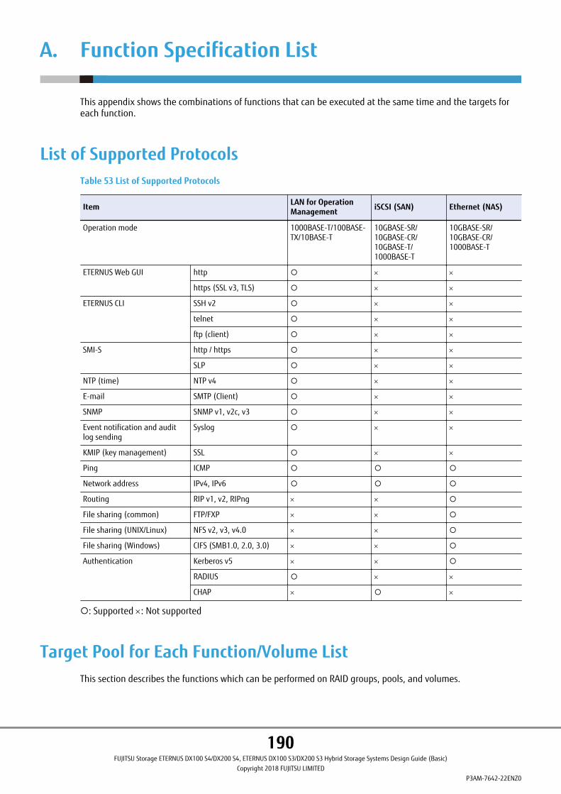
A. Function Specification List
This appendix shows the combinations of functions that can be executed at the same time and the targets foreach function.
List of Supported ProtocolsTable 53 List of Supported Protocols
Item LAN for OperationManagement iSCSI (SAN) Ethernet (NAS)
Operation mode 1000BASE-T/100BASE-TX/10BASE-T
10GBASE-SR/10GBASE-CR/10GBASE-T/1000BASE-T
10GBASE-SR/10GBASE-CR/1000BASE-T
ETERNUS Web GUI http ¡ ´ ´
https (SSL v3, TLS) ¡ ´ ´
ETERNUS CLI SSH v2 ¡ ´ ´
telnet ¡ ´ ´
ftp (client) ¡ ´ ´
SMI-S http / https ¡ ´ ´
SLP ¡ ´ ´
NTP (time) NTP v4 ¡ ´ ´
E-mail SMTP (Client) ¡ ´ ´
SNMP SNMP v1, v2c, v3 ¡ ´ ´
Event notification and auditlog sending
Syslog ¡ ´ ´
KMIP (key management) SSL ¡ ´ ´
Ping ICMP ¡ ¡ ¡
Network address IPv4, IPv6 ¡ ¡ ¡
Routing RIP v1, v2, RIPng ´ ´ ¡
File sharing (common) FTP/FXP ´ ´ ¡
File sharing (UNIX/Linux) NFS v2, v3, v4.0 ´ ´ ¡
File sharing (Windows) CIFS (SMB1.0, 2.0, 3.0) ´ ´ ¡
Authentication Kerberos v5 ´ ´ ¡
RADIUS ¡ ´ ´
CHAP ´ ¡ ´
¡: Supported ´: Not supported
Target Pool for Each Function/Volume ListThis section describes the functions which can be performed on RAID groups, pools, and volumes.
190FUJITSU Storage ETERNUS DX100 S4/DX200 S4, ETERNUS DX100 S3/DX200 S3 Hybrid Storage Systems Design Guide (Basic)
Copyright 2018 FUJITSU LIMITEDP3AM-7642-22ENZ0

Target RAID Groups/Pools of Each Function
Action RAID group REC Disk Buffer SDP TPP FTRP (*1) FTSP (*1)
Components Standard, SDV,WSV
— SDPV TPV FTSP FTV
Max.number
ETERNUSDX100 S4/DX100 S3
72 Up to two canbe specified perREC Buffer
1 72 (*2) 15 72 (*2)
ETERNUSDX200 S4/DX200 S3
132 1 132 (*2) (*3) 30 132 (*2)
Create ¡ ¡ — (*4) ¡ ¡ ¡
Delete ¡ ¡ — (*5) ¡ (*6) ¡ (*6) (*7) — (*7)
Rename ¡ ¡ ´ ¡ ¡ ¡
Expand capacity ¡ (by LDE) ´ ¡ (by addingan SDPV)
¡ (by addinga RAID group)
△ (by addinga child pool)
¡ (by adding aRAID group)
Migration ¡ ´ ´ ´ ´ ¡
Logical Device Expan-sion (LDE)
¡ ´ ¡ ´ ´ ´
Format (All area) ´ ¡ ´ ¡ ¡ — (*8)
Format (Unformattedarea)
´ ´ ´ ¡ ¡ — (*8)
Modify threshold ´ ´ ¡ ¡ ¡ — (*8)
Eco-mode setup ¡ ´ ´ ¡ ¡ ´
Switch controlling CM ¡ ¡ ¡ ¡ — ¡
Allocate REC Buffer ´ ¡ ´ ´ ´ ´
Key management serverlinkage
¡ ¡ ¡ ¡ ¡ ¡
¡: Possible ´: Impossible - : N/A
*1: Only ETERNUS SF Storage Cruiser can perform operations on FTRP and FTSP.
*2: The maximum total number of TPPs and FTSPs.
*3: The Deduplication/Compression function can be enabled for a maximum of four TPPs.
*4: If an SDPV is created, an SDP is automatically created.
*5: If all of the SDPVs are deleted, SDPs are automatically deleted.
*6: When a volume exists in a pool, the pool cannot be deleted.
*7: If an FTRP is deleted, the FTSP, which is included in the FTRP, is also deleted. The FTRP needs to be deletedto delete the FTSP.
*8: This operation is possible in units of parent pools (FTRPs).
A. Function Specification ListTarget Pool for Each Function/Volume List
191FUJITSU Storage ETERNUS DX100 S4/DX200 S4, ETERNUS DX100 S3/DX200 S3 Hybrid Storage Systems Design Guide (Basic)
Copyright 2018 FUJITSU LIMITEDP3AM-7642-22ENZ0
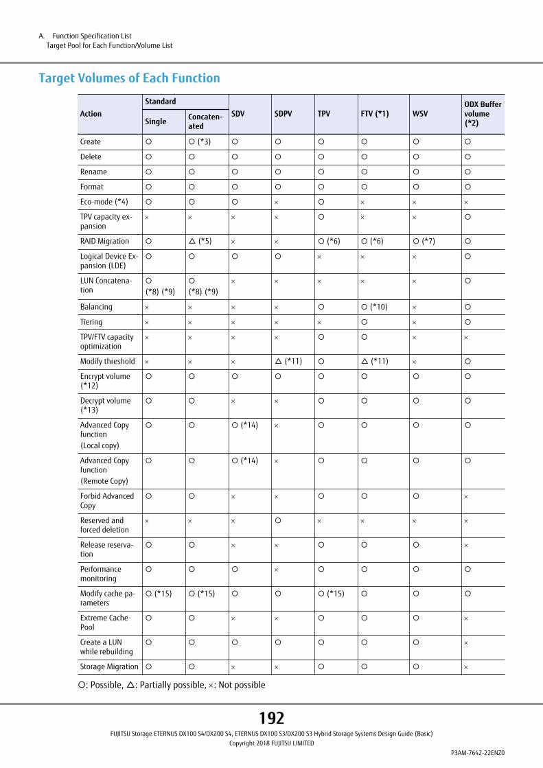
Target Volumes of Each Function
ActionStandard
SDV SDPV TPV FTV (*1) WSVODX Buffervolume(*2)Single Concaten-
ated
Create ¡ ¡ (*3) ¡ ¡ ¡ ¡ ¡ ¡
Delete ¡ ¡ ¡ ¡ ¡ ¡ ¡ ¡
Rename ¡ ¡ ¡ ¡ ¡ ¡ ¡ ¡
Format ¡ ¡ ¡ ¡ ¡ ¡ ¡ ¡
Eco-mode (*4) ¡ ¡ ¡ ´ ¡ ´ ´ ´
TPV capacity ex-pansion
´ ´ ´ ´ ¡ ´ ´ ¡
RAID Migration ¡ △ (*5) ´ ´ ¡ (*6) ¡ (*6) ¡ (*7) ¡
Logical Device Ex-pansion (LDE)
¡ ¡ ¡ ¡ ´ ´ ´ ¡
LUN Concatena-tion
¡
(*8) (*9)¡
(*8) (*9)´ ´ ´ ´ ´ ¡
Balancing ´ ´ ´ ´ ¡ ¡ (*10) ´ ¡
Tiering ´ ´ ´ ´ ´ ¡ ´ ¡
TPV/FTV capacityoptimization
´ ´ ´ ´ ¡ ¡ ´ ´
Modify threshold ´ ´ ´ △ (*11) ¡ △ (*11) ´ ¡
Encrypt volume(*12)
¡ ¡ ¡ ¡ ¡ ¡ ¡ ¡
Decrypt volume(*13)
¡ ¡ ´ ´ ¡ ¡ ¡ ¡
Advanced Copyfunction(Local copy)
¡ ¡ ¡ (*14) ´ ¡ ¡ ¡ ¡
Advanced Copyfunction(Remote Copy)
¡ ¡ ¡ (*14) ´ ¡ ¡ ¡ ¡
Forbid AdvancedCopy
¡ ¡ ´ ´ ¡ ¡ ¡ ´
Reserved andforced deletion
´ ´ ´ ¡ ´ ´ ´ ´
Release reserva-tion
¡ ¡ ´ ´ ¡ ¡ ¡ ´
Performancemonitoring
¡ ¡ ¡ ´ ¡ ¡ ¡ ¡
Modify cache pa-rameters
¡ (*15) ¡ (*15) ¡ ¡ ¡ (*15) ¡ ¡ ¡
Extreme CachePool
¡ ¡ ´ ´ ¡ ¡ ¡ ´
Create a LUNwhile rebuilding
¡ ¡ ¡ ¡ ¡ ¡ ¡ ´
Storage Migration ¡ ¡ ´ ´ ¡ ¡ ¡ ´
¡: Possible, △: Partially possible, ´: Not possible
A. Function Specification ListTarget Pool for Each Function/Volume List
192FUJITSU Storage ETERNUS DX100 S4/DX200 S4, ETERNUS DX100 S3/DX200 S3 Hybrid Storage Systems Design Guide (Basic)
Copyright 2018 FUJITSU LIMITEDP3AM-7642-22ENZ0

*1 : FTV operations can only be executed with ETERNUS SF Storage Cruiser.
FTRP balancing can be executed with either ETERNUS Web GUI or ETERNUS CLI.
*2 : An ODX Buffer volume is an exclusive volume that is required to perform ODX. Standard volumes, TPVs, orFTVs can be used for the ODX Buffer volume.
*3 : A concatenated volumes cannot be created at the same time as a volume. Existing volumes can be con-catenated by using LUN Concatenation.
*4 : Eco-mode is configured for Standard volumes/SDVs in RAID group units that include the target volume,and TPVs in pool (TPP) units.
*5 : If multiple volumes have been concatenated using the LUN Concatenation function, RAID Migration canbe executed only on concatenation source volumes.
*6 : Capacity expansion and RAID Migration cannot be performed at the same time.
*7 : The volume capacity can be expanded by specifying a relatively large capacity for the destination volumewhen RAID Migration is performed.
*8 : The maximum number of concatenated volumes is 16.
*9 : If T10-DIF is enabled, this function cannot be executed.
*10: Specify in units of FTRPs. FTVs that need balancing are automatically selected and balanced for each FTSP.
*11: A threshold can be set to the pool which includes the target volume.
*12: Encryption of Standard volumes and SDVs can be performed when the volumes are created, or after thevolumes have been created.
Encryption of SDPVs can be performed only when the volumes are created. SDPVs cannot be encryptedafter they are created.
Encryption of TPVs and FTVs is performed by creating a volume in the encrypted pool, or migrating a vol-ume to an encrypted pool.
*13: Decryption of volumes is performed by specifying "Unencrypted" for the migration destination when mi-grating the volumes.
*14: SDVs are used as the copy destination for SnapOPC/SnapOPC+. SDVs are also used as the copy source if thecopy destination of SnapOPC/SnapOPC+ is also set as the copy source (Cascade Copy/restore).
*15: This is part of the cache parameter settings, and cannot be configured in the units of volumes.
A. Function Specification ListTarget Pool for Each Function/Volume List
193FUJITSU Storage ETERNUS DX100 S4/DX200 S4, ETERNUS DX100 S3/DX200 S3 Hybrid Storage Systems Design Guide (Basic)
Copyright 2018 FUJITSU LIMITEDP3AM-7642-22ENZ0

Combinations of Functions That Are Available for SimultaneousExecutions
This section describes the availability of simultaneous execution with other functions, the number of processesthat can be executed concurrently, and the capacity that can be processed concurrently for each function.
Combinations of Functions That Are Available for Simultaneous ExecutionsThere are functions which cannot be performed concurrently when another function is being executed in theETERNUS DX.
The following table shows which function combinations can be executed at the same time.
Table 54 Combinations of Functions That Can Be Executed Simultaneously (1/2)
Process to berun
Already running process
Rebuild/Copyback/RedundantCopy
Fast Recov-ery
Format Vol-ume
RAID Migra-tion
Logical De-vice Expan-sion (LDE)
LUN Concat-enation
AdvancedCopy (*1)
Format Volume ¡ ¡ ¡ (*3) ¡ (*4) ¡ (*4) ¡ (*3) ¡ (*4)
RAID Migration ¡ ¡ ¡ (*4) ¡ (*4) ¡ (*4) ¡ (*5) ¡ (*6)
Logical DeviceExpansion
¡ (*7) ¡ ¡ (*7) ¡ (*7) ´ ¡ (*7) ¡
LUN Concatena-tion
¡ ¡ ¡ ¡ (*4) ¡ (*4) ¡ ¡ (*8)
Advanced Copy(*2)
¡ ¡ ¡ ¡ (*9) ¡ ¡ ¡ (*10)
Volume Conver-sion Encryption
¡ (*4) ¡ ¡ (*4) ¡ (*4) ¡ (*4) ¡ (*4) ¡
Switch control-ling CM
¡ (*7) ¡ (*7) ¡ (*7) ´ ´ ¡ (*7) ¡ (*11)
TPV capacity ex-pansion
¡ ¡ ¡ ¡ ¡ ¡ ¡ (*8)
TPV Balancing ¡ ¡ ¡ (*4) ¡ (*4) ¡ ¡ ¡ (*6)
TPV/FTV capacityoptimization
¡ ¡ ¡ ¡ (*4) ¡ ¡ ¡
FTRP Balancing ¡ ¡ ¡ ¡ ¡ ¡ ¡
¡: Possible, ´: Not possible
Table 55 Combinations of Functions That Can Be Executed Simultaneously (2/2)
Process to berun
Already running process
Volume Con-version En-cryption
Disk PatrolEco-mode(motor isstopped)
TPV Balanc-ing
TPV/FTV ca-pacity opti-mization
StorageCluster
Format Volume ¡ (*3) ¡ ¡ (*12) ¡ (*4) ¡ ¡ (*4)
RAID Migration ¡ (*4) ¡ ¡ (*12) ¡ (*4) ¡ (*4) ¡
Logical DeviceExpansion
¡ (*7) ¡ ¡ (*12) ¡ ¡ ¡
A. Function Specification ListCombinations of Functions That Are Available for Simultaneous Executions
194FUJITSU Storage ETERNUS DX100 S4/DX200 S4, ETERNUS DX100 S3/DX200 S3 Hybrid Storage Systems Design Guide (Basic)
Copyright 2018 FUJITSU LIMITEDP3AM-7642-22ENZ0

Process to berun
Already running process
Volume Con-version En-cryption
Disk PatrolEco-mode(motor isstopped)
TPV Balanc-ing
TPV/FTV ca-pacity opti-mization
StorageCluster
LUN Concatena-tion
¡ (*4) ¡ ¡ (*12) ¡ ¡ ¡ (*4)
Advanced Copy(*2)
¡ ¡ ¡ (*13) ¡ ¡ ¡
Volume Conver-sion Encryption
¡ (*4) ¡ ¡ (*12) ¡ ¡ ¡
Switch control-ling CM
¡ (*7) ¡ ¡ ¡ ¡ ¡
TPV capacity ex-pansion
¡ ¡ ¡ (*12) ¡ (*4) ¡ ¡
TPV Balancing ¡ ¡ ¡ (*12) ¡ (*4) ¡ (*4) ¡
TPV/FTV capacityoptimization
¡ ¡ ¡ (*12) ¡ (*4) ´ ¡
FTRP Balancing ¡ ¡ ¡ (*12) ¡ (*4) ¡ (*4) ¡
¡: Possible, ´: Not possible
*1 : This indicates that the copy session is being set or the copy session is already set.
*2 : This indicates the copy session setting operation.
*3 : Using the "Format Volume" function will cause losing the entire data in volumes.
*4 : The function cannot be executed when the same volume is set as the execution target.
*5 : LUN concatenated volumes can be set as the RAID Migration source.
Note that LUN concatenated volumes cannot be set as the RAID Migration destination.
*6 : RAID Migration that expands the capacity cannot be performed on any volumes with copy sessions in LUNunits.
*7 : The function cannot be executed when the same RAID group is set as the execution target.
*8 : When a copy session with a copy area that is specified in LUN units exists, volume capacity expansioncannot be performed because copying cannot be processed for the expanded part. When a copy session isspecified for a logical disk, volume capacity expansion can be performed.
*9 : Copy sessions in LUN units cannot be performed on a volume that is being expanded with RAID Migration.
*10: Complies with Advanced Copy specifications (multi-copy/Cascade Copy).
*11: The REC session needs to be suspended or stopped before the operation.
*12: The motor-off state of Eco-mode is stopped, and the drive motor is activated (spin-up).
*13: EC/REC can be performed (The motor-off state of Eco-mode will be stopped).
OPC/QuickOPC/SnapOPC/SnapOPC+ cannot be performed (the ETERNUS DX returns an error).
A. Function Specification ListCombinations of Functions That Are Available for Simultaneous Executions
195FUJITSU Storage ETERNUS DX100 S4/DX200 S4, ETERNUS DX100 S3/DX200 S3 Hybrid Storage Systems Design Guide (Basic)
Copyright 2018 FUJITSU LIMITEDP3AM-7642-22ENZ0
Number of Processes That Can Be Executed SimultaneouslyThe following upper limits are applied to the number of processes that are to be executed.
• Only one process can be executed with Logical Device Expansion (LDE). Two or more processes cannot be exe-cuted simultaneously in the same device.
• The total number of TPV balancing, FTRP balancing, RAID Migration, and Flexible Tier Migration processes thatcan be performed at the same time is 32.
Capacity That Can Be Processed SimultaneouslyThe following upper limit is applied to the capacity of processes that are to be executed.
• The total capacity of TPV balancing, FTRP balancing, RAID Migration, and Flexible Tier Migration processes thatcan be performed at the same time is 128TB.
A. Function Specification ListCombinations of Functions That Are Available for Simultaneous Executions
196FUJITSU Storage ETERNUS DX100 S4/DX200 S4, ETERNUS DX100 S3/DX200 S3 Hybrid Storage Systems Design Guide (Basic)
Copyright 2018 FUJITSU LIMITEDP3AM-7642-22ENZ0

FUJITSU Storage ETERNUS DX100 S4/DX200 S4, ETERNUS DX100 S3/DX200 S3 Hybrid Storage SystemsDesign Guide (Basic)
P3AM-7642-22ENZ0
Date of issuance: April 2018Issuance responsibility: FUJITSU LIMITED
• The content of this manual is subject to change without notice.
• This manual was prepared with the utmost attention to detail.
However, Fujitsu shall assume no responsibility for any operational problems as the result of errors, omissions, or theuse of information in this manual.
• Fujitsu assumes no liability for damages to third party copyrights or other rights arising from the use of any informationin this manual.
• The content of this manual may not be reproduced or distributed in part or in its entirety without prior permission fromFujitsu.