dwm1001 firmware application programming …
TRANSCRIPT
© Decawave Ltd 2018 SW-DWM1001-API-Guide-2.1 Page 1 of 89
DWM1001 FIRMWARE
APPLICATION
PROGRAMMING
INTERFACE (API) GUIDE
USING API FUNCTIONS TO
CONFIGURE AND PROGRAMME
DWM1001 MODULE
This document is subject to change without notice
DW1001 Firmware API Guide
© Decawave Ltd 2018 SW-DWM1001-API-Guide-2.1 Page 2 of 89
TABLE OF CONTENTS
DISCLAIMER ................................................................................................................................................ 7
1 INTRODUCTION AND OVERVIEW ........................................................................................................... 10
1.1 DWM1001 MODULE AND THE FIRMWARE ................................................................................................... 10
1.2 API AND ITS GUIDE ................................................................................................................................... 10
2 GENERAL API DESCRIPTIONS ................................................................................................................. 11
2.1 EXTERNAL INTERFACE USAGE ...................................................................................................................... 11
2.2 LOW POWER MODE WAKE-UP MECHANISM ................................................................................................... 11
2.3 TLV FORMAT........................................................................................................................................... 11
2.4 DWM1001 THREADS .............................................................................................................................. 11
2.5 API VIA BLE INTERFACE ............................................................................................................................. 12
2.6 API VIA SPI INTERFACE ............................................................................................................................. 12
2.6.1 DWM1001 SPI overview .................................................................................................................. 12
2.6.2 SPI Scheme: normal TLV communication ........................................................................................ 15
2.6.3 SPI Example: normal TLV communication - dwm_gpio_cfg_output .............................................. 16
2.6.4 SPI Scheme: TLV communication using data ready pin ................................................................... 17
2.6.5 SPI error recovery mechanism ........................................................................................................ 18
2.7 API VIA UART INTERFACE ......................................................................................................................... 19
2.7.1 DWM1001 UART overview.............................................................................................................. 19
2.7.2 UART TLV Mode .............................................................................................................................. 19
2.7.3 UART scheme: TLV mode communication ...................................................................................... 20
2.7.4 UART example: TLV mode communication ..................................................................................... 21
2.7.5 UART scheme: Shell mode communication ..................................................................................... 21
2.7.6 UART example: Shell Mode communication ................................................................................... 22
2.8 GPIO SCHEME: DWM1001 NOTIFIES FOR STATUS CHANGE ............................................................................ 22
2.9 API FOR ON-BOARD C CODE DEVELOPERS ..................................................................................................... 23
3 GENERIC API INFORMATION .................................................................................................................. 24
3.1 USED TERMINOLOGY ................................................................................................................................. 24
3.2 LITTLE ENDIAN ......................................................................................................................................... 24
3.3 FIRMWARE UPDATE .................................................................................................................................. 24
3.4 FREQUENTLY USED TLV VALUES .................................................................................................................. 25
3.4.1 err_code .......................................................................................................................................... 25
3.4.2 position ........................................................................................................................................... 25
3.4.3 gpio_idx .......................................................................................................................................... 25
3.4.4 gpio_value ...................................................................................................................................... 25
3.4.5 gpio_pull ......................................................................................................................................... 26
3.4.6 fw_version ....................................................................................................................................... 26
3.4.7 cfg_tag ............................................................................................................................................ 26
3.4.8 cfg_anchor ...................................................................................................................................... 26
3.4.9 cfg_node ......................................................................................................................................... 27
4 API FUNCTION DESCRIPTIONS ............................................................................................................... 28
4.1 LIST OF API FUNCTIONS ............................................................................................................................. 28
4.2 USAGE OF THE APIS ................................................................................................................................. 29
4.3 DETAILS OF THE API FUNCTIONS ................................................................................................................. 29

DW1001 Firmware API Guide
© Decawave Ltd 2018 SW-DWM1001-API-Guide-2.1 Page 3 of 89
4.3.1 dwm_pos_set .................................................................................................................................. 30
4.3.2 dwm_pos_get ................................................................................................................................. 31
4.3.3 dwm_upd_rate_set ......................................................................................................................... 32
4.3.4 dwm_upd_rate_get ........................................................................................................................ 33
4.3.5 dwm_cfg_tag_set ........................................................................................................................... 34
4.3.6 dwm_cfg_anchor_set ..................................................................................................................... 36
4.3.7 dwm_cfg_get .................................................................................................................................. 37
4.3.8 dwm_sleep ...................................................................................................................................... 39
4.3.9 dwm_loc_get .................................................................................................................................. 40
4.3.10 dwm_baddr_set.......................................................................................................................... 42
4.3.11 dwm_baddr_get ......................................................................................................................... 43
4.3.12 dwm_reset .................................................................................................................................. 44
4.3.13 dwm_ver_get.............................................................................................................................. 45
4.3.14 dwm_usr_data_read .................................................................................................................. 46
4.3.15 dwm_usr_data_write ................................................................................................................. 47
4.3.16 dwm_label_read ......................................................................................................................... 48
4.3.17 dwm_label_write ........................................................................................................................ 49
4.3.18 dwm_gpio_cfg_output ............................................................................................................... 50
4.3.19 dwm_gpio_cfg_input.................................................................................................................. 51
4.3.20 dwm_gpio_value_set ................................................................................................................. 52
4.3.21 dwm_gpio_value_get ................................................................................................................. 53
4.3.22 dwm_gpio_value_toggle ............................................................................................................ 54
4.3.23 dwm_panid_set .......................................................................................................................... 55
4.3.24 dwm_panid_get ......................................................................................................................... 56
4.3.25 dwm_node_id_get ...................................................................................................................... 57
4.3.26 dwm_status_get ......................................................................................................................... 58
4.3.27 dwm_int_cfg_set ........................................................................................................................ 60
4.3.28 dwm_int_cfg_get ....................................................................................................................... 61
4.3.29 dwm_bh_status_get ................................................................................................................... 62
4.3.30 dwm_sec_key_set ...................................................................................................................... 63
4.3.31 dwm_gpio_irq_cfg ...................................................................................................................... 64
4.3.32 dwm_gpio_irq_dis ...................................................................................................................... 65
4.3.33 dwm_i2c_read ............................................................................................................................ 66
4.3.34 dwm_i2c_write ........................................................................................................................... 67
4.3.35 dwm_evt_cb_register ................................................................................................................. 68
4.3.36 dwm_evt_wait ............................................................................................................................ 69
5 UART SHELL COMMANDS ...................................................................................................................... 72
5.1 COMMAND GROUP: BASE ......................................................................................................................... 72
5.1.1 ? (question mark) ............................................................................................................................ 72
5.1.2 help ................................................................................................................................................. 72
5.1.3 quit .................................................................................................................................................. 72
5.2 COMMAND GROUP: GPIO ......................................................................................................................... 73
5.2.1 gc: GPIO clear .................................................................................................................................. 73
5.2.2 gg: GPIO get .................................................................................................................................... 73
5.2.3 gs: GPIO set ..................................................................................................................................... 73
5.2.4 gt: GPIO toggle................................................................................................................................ 73
5.3 COMMAND GROUP: SYS ........................................................................................................................... 74
5.3.1 f: Show free memory on the heap ................................................................................................... 74
DW1001 Firmware API Guide
© Decawave Ltd 2018 SW-DWM1001-API-Guide-2.1 Page 4 of 89
5.3.2 ps: Show running threads ............................................................................................................... 74
5.3.3 pms: Show PM tasks ....................................................................................................................... 74
5.3.4 reset: Reboot the system ................................................................................................................ 75
5.3.5 si: System info ................................................................................................................................. 75
5.3.6 ut: Show device uptime ................................................................................................................... 76
5.3.7 frst: Factory reset ............................................................................................................................ 76
5.4 COMMAND GROUP: SENS ......................................................................................................................... 76
5.4.1 twi: General purpose TWI read ....................................................................................................... 76
5.4.2 aid: Read ACC device ID .................................................................................................................. 76
5.4.3 Av: Read ACC values. ....................................................................................................................... 77
5.5 COMMAND GROUP: CRYPTO .................................................................................................................... 77
5.5.1 cks: set 128-bit encryption key ........................................................................................................ 77
5.6 COMMAND GROUP: LE ............................................................................................................................. 77
5.6.1 les: Show meas. and pos. ................................................................................................................ 77
5.6.2 lec: Show meas. and pos. in CSV ..................................................................................................... 78
5.6.3 lep: Show pos. in CSV ...................................................................................................................... 78
5.7 COMMAND GROUP: UWBMAC ................................................................................................................. 78
5.7.1 nmg: Get node mode ...................................................................................................................... 78
5.7.2 nmp: Set mode to PN (passive) ....................................................................................................... 79
5.7.3 nmo: Set mode to PN (off) .............................................................................................................. 79
5.7.4 nma: Set mode to AN ...................................................................................................................... 79
5.7.5 nmi: Set mode to AIN ...................................................................................................................... 79
5.7.6 nmt: Set mode to TN ....................................................................................................................... 79
5.7.7 nmtl: Set mode to TN-LP ................................................................................................................. 79
5.7.8 nmb: Set mode to BN ...................................................................................................................... 80
5.7.9 bpc: Toggle BW/TxPWR comp ........................................................................................................ 80
5.7.10 la: Show AN list ........................................................................................................................... 80
5.7.11 ln: list BH nodes .......................................................................................................................... 80
5.7.12 lr: list routes ................................................................................................................................ 81
5.7.13 lr: list next routes ........................................................................................................................ 81
5.7.14 nis: set Network PAN ID .............................................................................................................. 82
5.7.15 nls: Set node label ....................................................................................................................... 82
5.7.16 stg: Get stats .............................................................................................................................. 82
5.7.17 stc: Clear stats ............................................................................................................................ 83
5.7.18 udi: Show received IoT data ........................................................................................................ 83
5.7.19 uui: Send IoT data ....................................................................................................................... 83
5.8 COMMAND GROUP: API ............................................................................................................................ 83
5.8.1 tlv: Send TLV frame ......................................................................................................................... 84
5.8.2 aurs: Set upd rate ............................................................................................................................ 84
5.8.3 aurg: Get upd rate .......................................................................................................................... 84
5.8.4 apg: Get pos .................................................................................................................................... 84
5.8.5 aps : Set pos .................................................................................................................................... 84
5.8.6 acas: Set anchor config ................................................................................................................... 85
5.8.7 acts: Set tag config.......................................................................................................................... 85
6 APPENDIX A – TLV TYPE LIST .................................................................................................................. 86
7 APPENDIX B – BIBLIOGRAPHY ................................................................................................................ 87
8 DOCUMENT HISTORY ............................................................................................................................ 88
9 FURTHER INFORMATION ....................................................................................................................... 89

DW1001 Firmware API Guide
© Decawave Ltd 2018 SW-DWM1001-API-Guide-2.1 Page 5 of 89
List of Tables
TABLE 1 TLV FORMAT DATA EXAMPLE ........................................................................................................................... 11
TABLE 2 API REQUEST FUNCTION LIST ............................................................................................................................ 28
TABLE 3 API EXAMPLES LOCATION ................................................................................................................................ 29
TABLE 4 DWM1001 TLV TYPE LIST ............................................................................................................................. 86
TABLE 5: DOCUMENT HISTORY ..................................................................................................................................... 88
List of Figures
FIGURE 1 DWM1001 SPI WORK FLOW ........................................................................................................................ 13
FIGURE 2 SPI SCHEME: NORMAL TLV COMMUNICATION ................................................................................................... 15
FIGURE 3 SPI EXAMPLE: NORMAL TLV COMMUNICATION .................................................................................................. 16
FIGURE 4 SPI SCHEME: TLV COMMUNICATION USING DATA READY PIN ................................................................................ 17
FIGURE 5 DWM1001 UART WORK FLOW .................................................................................................................... 19
FIGURE 6 UART SCHEME: TLV MODE COMMUNICATION .................................................................................................. 20
FIGURE 7 UART EXAMPLE: TLV MODE COMMUNICATION ................................................................................................. 21
FIGURE 8 UART SCHEME: SHELL MODE COMMUNICATION ................................................................................................ 22
FIGURE 9 UART EXAMPLE: SHELL MODE COMMUNICATION ............................................................................................... 22
FIGURE 10 GPIO SCHEME: DWM1001 NOTIFIES HOST DEVICE OF STATUS CHANGE, USING GPIO............................................ 23
DW1001 Firmware API Guide
© Decawave Ltd 2018 SW-DWM1001-API-Guide-2.1 Page 6 of 89
DOCUMENT INFORMATION
Disclaimer
Decawave reserves the right to change product specifications without notice. As far as possible changes to
functionality and specifications will be issued in product specific errata sheets or in new versions of this
document. Customers are advised to check the Decawave website for the most recent updates on this
product
Copyright © 2017 Decawave Ltd
LIFE SUPPORT POLICY
Decawave products are not authorized for use in safety-critical applications (such as life support) where a
failure of the Decawave product would reasonably be expected to cause severe personal injury or death.
Decawave customers using or selling Decawave products in such a manner do so entirely at their own risk
and agree to fully indemnify Decawave and its representatives against any damages arising out of the use of
Decawave products in such safety-critical applications.
Caution! ESD sensitive device.
Precaution should be used when handling the device in order to prevent permanent damage

DW1001 Firmware API Guide
© Decawave Ltd 2018 SW-DWM1001-API-Guide-2.1 Page 7 of 89
DISCLAIMER
(1) This Disclaimer applies to the software provided by Decawave Ltd. (“Decawave”) in
support of its DWM1001 module product (“Module”) all as set out at clause 3 herein
(“Decawave Software”).
(2) Decawave Software is provided in two ways as follows: -
(a) pre-loaded onto the Module at time of manufacture by Decawave (“Firmware”);
(b) supplied separately by Decawave (“Software Bundle”).
(3) Decawave Software consists of the following components (a) to (d) inclusive:
(a) The Decawave Positioning and Networking Stack (“PANS”), available as a
library accompanied by source code that allows a level of user customisation.
The PANS software is pre-installed and runs on the Module as supplied, and
enables mobile “tags”, fixed “anchors” and “gateways” that together deliver the
DWM1001 Two-Way-Ranging Real Time Location System (“DRTLS”)
Network.
(b) The Decawave DRTLS Manager which is an Android™ application for
configuration of DRTLS nodes (nodes based on the Module) over Bluetooth™.
(c) The Decawave DRTLS Gateway Application which supplies a gateway
function (on a Raspberry Pi ®) routing DRTLS location and sensor data traffic
onto an IP based network (e.g. LAN), and consists of the following components:
• DRTLS Gateway Linux Kernel Module
• DRTLS Gateway Daemon
• DRTLS Gateway MQTT Broker
• DRTLS Gateway Web Manager
(d) Example Host API functions, also designed to run on a Raspberry Pi, which
show how to drive the Module from an external host microprocessor.
(4) The following third party components are used by Decawave Software and are
incorporated in the Firmware or included in the Software Bundle as the case may be: -
(a) The PANS software incorporates the Nordic SoftDevice S132-SD-v3 version
3.0.0 (production) which is included in the Firmware and is also included in the
Software Bundle;
(b) The PANS software uses the eCos RTOS which is included in the Software
Bundle. The eCos RTOS is provided under the terms of an open source licence
which may be found at: http://ecos.sourceware.org/license-overview.html;
(c) The PANS software uses an open source CRC-32 function from FreeBSD which
is included in the Software Bundle. This CRC-32 function is provided under the
terms of the BSD licence which may be found at:
https://github.com/freebsd/freebsd/blob/386ddae58459341ec56760470780581
4a2128a57/COPYRIGHT;
DW1001 Firmware API Guide
© Decawave Ltd 2018 SW-DWM1001-API-Guide-2.1 Page 8 of 89
(d) The Decawave DRTLS Manager application uses open source software which
is provided as source code in the Software Bundle. This open source software
is provided under the terms of the Apache Licence v2.0 which may be found at
http://www.apache.org/licenses/LICENSE-2.0;
(e) The Decawave DRTLS Gateway Application uses the following third party
components: -
(i) The Linux Kernel which is provided as source code in the Software
Bundle. The Linux Kernel is provided under the terms of the GPLv2
licence which may be found at: https://www.gnu.org/licenses/old-
licenses/gpl-2.0.en.html and as such the DWM1001 driver component
of the DRTLS Gateway Application is provided under the same license
terms;
(ii) The three.js JavaScript library, the downloadable version of which is
available here https://threejs.org/, is provided under the terms of the MIT
Licence which may be found at https://opensource.org/licenses/MIT.
Items (a), (b), (c), (d) and (e) in this section 4 are collectively referred to as the “Third
Party Software”
(5) Decawave Software incorporates source code licensed to Decawave by Leaps s.r.o., a
supplier to Decawave, which is included in the Firmware and the Software Bundle in
binary and/or source code forms as the case may be, under the terms of a license
agreement entered into between Decawave and Leaps s.r.o.
(6) Decawave hereby grants you a free, non-exclusive, non-transferable, worldwide license
without the right to sub-license to design, make, have made, market, sell, have sold or
otherwise dispose of products incorporating Decawave Software, to modify Decawave
Software or incorporate Decawave Software in other software and to design, make,
have made, market, sell, have sold or otherwise dispose of products incorporating such
modified or incorporated software PROVIDED ALWAYS that the use by you of Third
Party Software as supplied by Decawave is subject to the terms and conditions of the
respective license agreements as set out at clause 4 herein AND PROVIDED ALWAYS
that Decawave Software is used only in systems and products based on Decawave
semiconductor products. NO OTHER LICENSE, EXPRESS OR IMPLIED, BY
ESTOPPEL OR OTHERWISE TO ANY OTHER DECAWAVE INTELLECTUAL
PROPERTY RIGHT, AND NO LICENSE TO ANY THIRD PARTY TECHNOLOGY
OR INTELLECTUAL PROPERTY RIGHT, IS GRANTED HEREIN, including but
not limited to any patent right, copyright, mask work right, or other intellectual property
right relating to any combination, machine, or process in which Decawave
semiconductor products or Decawave Software are used.
(7) Downloading, accepting delivery of or using Decawave Software indicates your
agreement to the terms of (i) the license grated at clause 6 herein, (ii) the terms of this
Disclaimer and (iii) the terms attaching to the Third Party Software. If you do not agree
with all of these terms do not download, accept delivery of or use Decawave Software.
(8) Decawave Software is solely intended to assist you in developing systems that
incorporate Decawave semiconductor products. You understand and agree that you
DW1001 Firmware API Guide
© Decawave Ltd 2018 SW-DWM1001-API-Guide-2.1 Page 9 of 89
remain responsible for using your independent analysis, evaluation and judgment in
designing your systems and products. THE DECISION TO USE DECAWAVE
SOFTWARE IN WHOLE OR IN PART IN YOUR SYSTEMS AND PRODUCTS
RESTS ENTIRELY WITH YOU AND DECAWAVE ACCEPTS NO LIABILTY
WHATSOEVER FOR SUCH DECISION.
(9) DECAWAVE SOFTWARE IS PROVIDED "AS IS". DECAWAVE MAKES NO
WARRANTIES OR REPRESENTATIONS WITH REGARD TO DECAWAVE
SOFTWARE OR USE OF DECAWAVE SOFTWARE, EXPRESS, IMPLIED OR
STATUTORY, INCLUDING ACCURACY OR COMPLETENESS. DECAWAVE
DISCLAIMS ANY WARRANTY OF TITLE AND ANY IMPLIED WARRANTIES
OF MERCHANTABILITY, FITNESS FOR A PARTICULAR PURPOSE AND NON-
INFRINGEMENT OF ANY THIRD PARTY INTELLECTUAL PROPERTY
RIGHTS WITH REGARD TO DECAWAVE SOFTWARE OR THE USE THEREOF.
(10) DECAWAVE SHALL NOT BE LIABLE FOR AND SHALL NOT DEFEND OR
INDEMNIFY YOU AGAINST ANY THIRD PARTY INFRINGEMENT CLAIM
THAT RELATES TO OR IS BASED ON DECAWAVE SOFTWARE OR THE USE
OF DECAWAVE SOFTWARE. IN NO EVENT SHALL DECAWAVE BE LIABLE
FOR ANY ACTUAL, SPECIAL, INCIDENTAL, CONSEQUENTIAL OR
INDIRECT DAMAGES, HOWEVER CAUSED, INCLUDING WITHOUT
LIMITATION TO THE GENERALITY OF THE FOREGOING, LOSS OF
ANTICIPATED PROFITS, GOODWILL, REPUTATION, BUSINESS RECEIPTS
OR CONTRACTS, COSTS OF PROCUREMENT OF SUBSTITUTE GOODS OR
SERVICES; LOSS OF USE, DATA, OR PROFITS; OR BUSINESS
INTERRUPTION), LOSSES OR EXPENSES RESULTING FROM THIRD PARTY
CLAIMS. THESE LIMITATIONS WILL APPLY REGARDLESS OF THE FORM
OF ACTION, WHETHER UNDER STATUTE, IN CONTRACT OR TORT
INCLUDING NEGLIGENCE OR ANY OTHER FORM OF ACTION AND
WHETHER OR NOT DECAWAVE HAS BEEN ADVISED OF THE POSSIBILITY
OF SUCH DAMAGES, ARISING IN ANY WAY OUT OF DECAWAVE
SOFTWARE OR THE USE OF DECAWAVE SOFTWARE.
(11) You acknowledge and agree that you are solely responsible for compliance with all
legal, regulatory and safety-related requirements concerning your products, and any use
of Decawave Software in your applications, notwithstanding any applications-related
information or support that may be provided by Decawave.
(12) Decawave reserves the right to make corrections, enhancements, improvements and
other changes to its software, including Decawave Software, at any time.
Mailing address: Decawave Ltd.,
Adelaide Chambers,
Peter Street,
Dublin D08 T6YA
IRELAND.
Copyright (c) 15 November 2017 by Decawave Limited. All rights reserved. All trademarks
are the property of their respective owners.

DW1001 Firmware API Guide
© Decawave Ltd 2018 SW-DWM1001-API-Guide-2.1 Page 10 of 89
1 INTRODUCTION AND OVERVIEW
1.1 DWM1001 module and the firmware
The DWM1001 module is a radio transceiver module integrating the Nordic Semiconductor nRF52
MCU and Decawave’s DW1000 IC. The nRF52 MCU, which has Bluetooth v4.2 protocol stack
implemented [1], is acting as the main processor of the DWM1001 module. The DW1000 IC part,
which has the UWB physical layer defined in IEEE 802.15.4-2011 standard [2], is acting as the UWB
radio module controlled by the nRF52 MCU.
Decawave provides a pre-built firmware library, the “Positioning and Networking stack” (PANS) library,
in the DWM1001 module which runs on the nRF52 MCU. The firmware provides the Application
Programming Interface (API) for users to use their own host devices to communicate with the
DWM1001 module, namely the PANS API. The PANS API essentially is a set of functions providing a
means to communicate with the nRF52 MCU to drive the module through the PANS library on
application level without having to deal with the details of accessing the DW1000 IC part and other
peripherals directly through its SPI/I2C interface register set. The detailed information of the firmware
is introduced in the DWM1001 Firmware User Guide [3].
1.2 API and its guide
The PANS APIs are a set of functions. Each individual API function may be accessed through various
communication interfaces providing flexibility to developers in using the DWM1001 module and
integrating it into their systems. The API accesses mainly come in as two types:
1) External access API: via UART, SPI and BLE.
2) Integrated access API: via on-board user app (C code).
The detailed introduction to the flow with examples of how the API can be used is introduced in [3].
This document, “DWM1001 API Guide”, specifies the PANS API functions themselves, providing
descriptions of each of the API functions in detail in terms of its parameters, functionality and utility.
Users can use the PANS API to configure each individual DWM1001 module. To setup a location
system with multiple DWM1001 modules, users should refer to the DWM1001 System Guide [4].
This document relates to: "DWM1001 PANS Library Version 1.1.5"
DW1001 Firmware API Guide
© Decawave Ltd 2018 SW-DWM1001-API-Guide-2.1 Page 11 of 89
2 GENERAL API DESCRIPTIONS
2.1 External Interface usage
The external interfaces, including the UART, the SPI and the BLE, are used by the external APIs in the
PANS library for Host connection. The on-board user application through C code API cannot make
use of the external interfaces due to compatibility reasons.
2.2 Low power mode wake-up mechanism
As provided in the PANS library, the DWM1001 module can work in a low power mode. In the low
power mode, the module puts the API related threads into “sleep” state when the API is not
currently being communicated by host devices. In this case, the host device needs to wake up the
module through external interfaces before the real communication can start.
For UART interface, the host device needs to send a single byte first to wake up the module.
For SPI interface, putting the chip select pin to low level wakes up the module, i.e. no extra
transmission is needed.
After the API transmission has finished, the host device needs to put the module back to “sleep”
state to save power, as introduced in section 4.3.8 and section Error! Reference source not found..
2.3 TLV format
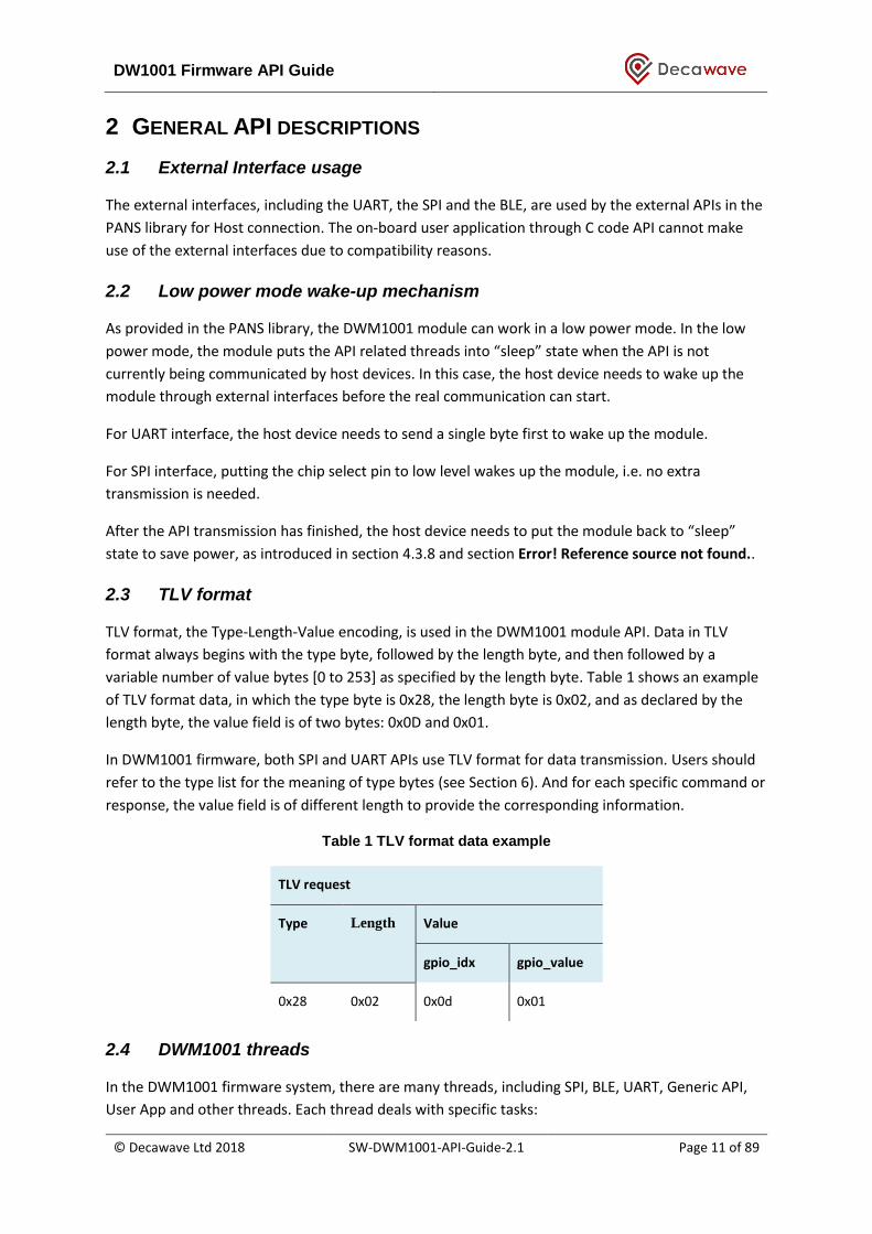
TLV format, the Type-Length-Value encoding, is used in the DWM1001 module API. Data in TLV
format always begins with the type byte, followed by the length byte, and then followed by a
variable number of value bytes [0 to 253] as specified by the length byte. Table 1 shows an example
of TLV format data, in which the type byte is 0x28, the length byte is 0x02, and as declared by the
length byte, the value field is of two bytes: 0x0D and 0x01.
In DWM1001 firmware, both SPI and UART APIs use TLV format for data transmission. Users should
refer to the type list for the meaning of type bytes (see Section 6). And for each specific command or
response, the value field is of different length to provide the corresponding information.
Table 1 TLV format data example
TLV request
Type Length Value
gpio_idx gpio_value
0x28 0x02 0x0d 0x01
2.4 DWM1001 threads
In the DWM1001 firmware system, there are many threads, including SPI, BLE, UART, Generic API,
User App and other threads. Each thread deals with specific tasks:

DW1001 Firmware API Guide
© Decawave Ltd 2018 SW-DWM1001-API-Guide-2.1 Page 12 of 89
The SPI, BLE and UART threads control the data transmission with external devices. They don’t parse
the requests they’ve received. All received requests are sent to the Generic API thread.
The Generic API thread is a parser of the received requests. It judges whether the incoming request
is valid. If valid, the firmware goes on to prepare the corresponding data as response; if invalid, the
firmware uses error message as response. Then the Generic API thread runs the call_back() function
which sends the prepared response message back to the thread where the request comes from.
The on-board user application thread is an independent thread for the users to add their own
functionalities. The entrance is provided in the dwm\example\ folder in the DWM1001 on-board
package. An example project is given in dwm\example\dwm-simple\ folder.
2.5 API via BLE interface
This is described in DWM1001-Bletooth-API document.
2.6 API via SPI interface
2.6.1 DWM1001 SPI overview
DWM1001 SPI interface uses TLV format data. Users can use an external host device in SPI master
mode to connect to the DWM1001 module SPI interface which operates in slave mode. The
maximum SPI clock frequency is 8 MHz. (This is maximum supported by the nRF52 MCU)
In the DWM1001 SPI schemes, host device communicates with the DWM1001 through TLV requests.
A full TLV request communication flow includes the following steps:
1) Host device sends TLV request;
2) DWM1001 prepares response;
3) Host device reads the length of total response;
4) Host device reads data response;
Because SPI uses full duplex communication, when the host device (as the SPI master) writes x bytes,
it actually sends x bytes to the DWM1001 module (as the slave), and receives x bytes dummy in the
same time. Similarly for reading, the host device sends x bytes of dummy, and receives x bytes data
back as response. In the DWM1001 SPI scheme, the dummy bytes are octets of value 0xFF.
DW1001 Firmware API Guide
© Decawave Ltd 2018 SW-DWM1001-API-Guide-2.1 Page 13 of 89
Read DATA/ERR
ReceivedTLV request
API: Idle
TLV request
TLV valid?
Prepare SIZE & DATA
Prepare SIZE & ERR
call_back()
No
Yes
Init SPI as Slave
SPI:Idle
SPI: Wait forcall_back()
SPI: Wait forRead SIZE
SPI: Wait forRead DATA/ERR
Receive any byte
Generic API threadSPI thread
Read SIZE
User activitySystem activitySystem status
call_back()
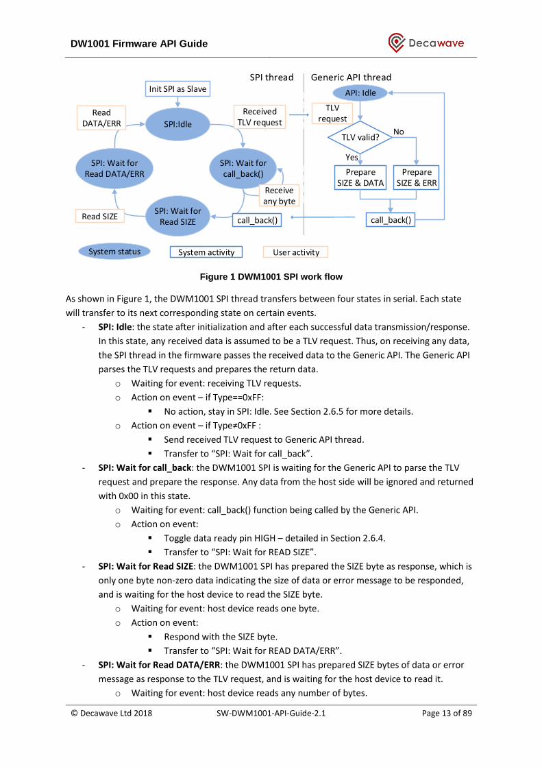
Figure 1 DWM1001 SPI work flow
As shown in Figure 1, the DWM1001 SPI thread transfers between four states in serial. Each state
will transfer to its next corresponding state on certain events.
- SPI: Idle: the state after initialization and after each successful data transmission/response.
In this state, any received data is assumed to be a TLV request. Thus, on receiving any data,
the SPI thread in the firmware passes the received data to the Generic API. The Generic API
parses the TLV requests and prepares the return data.
o Waiting for event: receiving TLV requests.
o Action on event – if Type==0xFF:
▪ No action, stay in SPI: Idle. See Section 2.6.5 for more details.
o Action on event – if Type≠0xFF :
▪ Send received TLV request to Generic API thread.
▪ Transfer to “SPI: Wait for call_back”.
- SPI: Wait for call_back: the DWM1001 SPI is waiting for the Generic API to parse the TLV
request and prepare the response. Any data from the host side will be ignored and returned
with 0x00 in this state.
o Waiting for event: call_back() function being called by the Generic API.
o Action on event:
▪ Toggle data ready pin HIGH – detailed in Section 2.6.4.
▪ Transfer to “SPI: Wait for READ SIZE”.
- SPI: Wait for Read SIZE: the DWM1001 SPI has prepared the SIZE byte as response, which is
only one byte non-zero data indicating the size of data or error message to be responded,
and is waiting for the host device to read the SIZE byte.
o Waiting for event: host device reads one byte.
o Action on event:
▪ Respond with the SIZE byte.
▪ Transfer to “SPI: Wait for READ DATA/ERR”.
- SPI: Wait for Read DATA/ERR: the DWM1001 SPI has prepared SIZE bytes of data or error
message as response to the TLV request, and is waiting for the host device to read it.
o Waiting for event: host device reads any number of bytes.

DW1001 Firmware API Guide
© Decawave Ltd 2018 SW-DWM1001-API-Guide-2.1 Page 14 of 89
o Action on event:
▪ Respond with DATA/ERR.
▪ Toggle data ready pin LOW – detailed in Section 2.6.4.
▪ Transfer to “SPI: Idle”.
In DWM1001, starting from “SPI: Idle”, traversing all four states listed above and returning to “SPI:
Idle” indicates a full TLV request communication flow. The user should have received the response
data or error message by the end of the communication flow.
A few different usages and examples are illustrated in the following sub-sections.

DW1001 Firmware API Guide
© Decawave Ltd 2018 SW-DWM1001-API-Guide-2.1 Page 15 of 89
2.6.2 SPI Scheme: normal TLV communication
Figure 2 shows the normal communication flow of a host device writing/reading information to/from
the DWM1001 module:
1) Host device sends the request in TLV format.
2) Host device reads the SIZE byte, indicating the number of bytes ready to be read.
a. On receiving SIZE= 0, meaning the response is not ready yet, repeat step 2).
b. On receiving SIZE > 0, meaning the response is ready, go to step 3)
3) Host device reads SIZE bytes data response in TLV format.
Figure 2 SPI scheme: normal TLV communication
DW1001 Firmware API Guide
© Decawave Ltd 2018 SW-DWM1001-API-Guide-2.1 Page 16 of 89
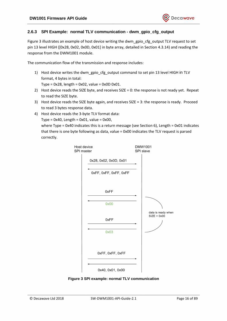
2.6.3 SPI Example: normal TLV communication - dwm_gpio_cfg_output
Figure 3 illustrates an example of host device writing the dwm_gpio_cfg_output TLV request to set
pin 13 level HIGH ([0x28, 0x02, 0x0D, 0x01] in byte array, detailed in Section 4.3.14) and reading the
response from the DWM1001 module.
The communication flow of the transmission and response includes:
1) Host device writes the dwm_gpio_cfg_output command to set pin 13 level HIGH in TLV
format, 4 bytes in total:
Type = 0x28, length = 0x02, value = 0x0D 0x01.
2) Host device reads the SIZE byte, and receives SIZE = 0: the response is not ready yet. Repeat
to read the SIZE byte.
3) Host device reads the SIZE byte again, and receives SIZE = 3: the response is ready. Proceed
to read 3 bytes response data.
4) Host device reads the 3-byte TLV format data:
Type = 0x40, Length = 0x01, value = 0x00,
where Type = 0x40 indicates this is a return message (see Section 6), Length = 0x01 indicates
that there is one byte following as data, value = 0x00 indicates the TLV request is parsed
correctly.
Figure 3 SPI example: normal TLV communication

DW1001 Firmware API Guide
© Decawave Ltd 2018 SW-DWM1001-API-Guide-2.1 Page 17 of 89
2.6.4 SPI Scheme: TLV communication using data ready pin
Similar to the scheme described in Section 2.6.2, users can setup the data ready pin (GPIO P0.26)
from the DWM1001 to indicate when data is ready, instead of the master polling multiple times to
check the response status. When the data ready function is setup, the data ready pin will be set to
LOW level when there’s no data to be read; when the response SIZE and data is ready to be read, the
data ready pin will be set to HIGH level during states “SPI: Wait for Read SIZE” and “SPI: Wait for
Read DATA/ERR”. Thus, the users can use the data ready pin either as an interrupt or as a status pin.
To setup data ready pin for SPI scheme, users need to use dwm_int_cfg TLV request through SPI
Scheme: normal TLV communication introduced in Section 2.6.2. The detail of dwm_int_cfg request
is introduced in Section 4.3.14.
The communication flow of this scheme is illustrated in Figure 4.
1) Setup the SPI interrupt.
2) Host device writes the request in TLV format.
3) Host device waits until the data ready pin on DWM1001 to go HIGH.
4) Host device reads the SIZE byte.
5) Host device reads SIZE bytes data response in TLV format
Figure 4 SPI scheme: TLV communication using data ready pin
As can be seen from the steps, this scheme is using the data ready pin on the DWM1001 to indicate
the host device when the response data is ready. This makes the host device less busy in reading
SIZE byte.
DW1001 Firmware API Guide
© Decawave Ltd 2018 SW-DWM1001-API-Guide-2.1 Page 18 of 89
2.6.5 SPI error recovery mechanism
2.6.5.1 SPI data doesn’t allow partial transmission
When reading data from the DWM1001 module, if the host device doesn’t read all bytes of data in
one transmission, the reading operation will still be considered as done. The rest of the response will
be abandoned. For example, in “SPI: Wait for Read DATA/ERR” state, the DWM1001 module has
prepared SIZE bytes of response data and expects the host device to read all SIZE bytes of the
response. However, if the host device only reads part of the data, the DWM1001 module will drop
the rest of the data, and transfers to the next state: “SPI: IDLE”.
2.6.5.2 SPI state recovery: type_nop message
The DWM1001 SPI has a special Type value 0xFF, called type_nop. A TLV data message with
type_nop means no operation. In “SPI: IDLE” state, when the DWM1001 SPI receives a message and
finds the type byte is 0xFF, it will not perform any operation, including sending the TLV data message
to the Generic API thread.
The type_nop is designed for error recovery. If the host device is not sure what state the DWM1001
SPI is in, it can make use of the SPI response and the non-partial transmission mechanism, and reset
the DWM1001 SPI to “SPI: IDLE” state by sending three 0xFF dummy bytes, each in a single
transmission. After the three transmissions, the response data from the DWM1001 SPI will become
all dummy bytes of value 0xFF, indicating that the DWM1001 SPI is in “SPI: IDLE” state.

DW1001 Firmware API Guide
© Decawave Ltd 2018 SW-DWM1001-API-Guide-2.1 Page 19 of 89
2.7 API via UART interface
2.7.1 DWM1001 UART overview
Users can use an external host device to connect to the DWM1001 module through UART interface
at baud rate 115200. Figure 5 shows the work flow of the DWM1001 UART interface. In the UART
Generic mode communication, the host device is acting as the initiator, while the DWM1001 module
is the responder.
DWM1001 UART provides two modes: the UART Generic mode, commands introduced in Section 4,
and the UART Shell mode, commands introduced in Section 4.3.36. The default mode of the
DWM1001 UART is Generic mode. However, the two modes are transferrable:
Generic mode to Shell mode: press “Enter” twice or input two bytes [0x0D, 0x0D] within one second.
If the module is in “sleep” state in low power mode as introduced in Section 2.2, an extra byte will
be needed before the double “Enter”. E.g. pressing “Enter” three times will wake up the module and
transfer it to Shell mode.
Shell mode to Generic mode: users need to input “quit” command.
Init UART
UART:Idle
UART:Receiving UART:Finished
Received any byte
Shell mode
Received double “Enter”
ReceivedTLV request
API:Idle
TLV request
TLV good?
Prepare data response
Prepare error message
call_back()
No
Yes
call_back()
User activitySystem activitySystem status
Generic API threadUART thread
quit cmd
Shell cmd
Figure 5 DWM1001 UART work flow
2.7.2 UART TLV Mode
UART TLV mode uses TLV format data. In this mode, host device and the DWM1001 module
communicate using TLV requests/responses. A full TLV request communication flow includes the
following steps:
1) Host device sends TLV request;
2) DWM1001 responds with TLV data.
On receiving any data, the UART starts a delay timer for the following data. If there is new data
coming in within a delay period, specifically 25 clock cycles (25/32768 second ≈ 763 µs), the UART
starts the delay timer and waits for new data. If there’s no new data coming in within the delay
period, the delay timer will expire. The UART then sends the received data to the Generic API thread
and waits for it to return the response data or error message.
DW1001 Firmware API Guide
© Decawave Ltd 2018 SW-DWM1001-API-Guide-2.1 Page 20 of 89
As shown in Figure 5, the DWM1001 UART TLV mode thread transfers between three states in serial:
“UART: Idle”, “UART: Receiving” and “UART: Finished”. Each state will transfer to its next
corresponding state on certain events.
- UART: Idle: is the state after initialization and after each successful TLV response. In this
state, the UART is only expecting one byte as the start of the TLV request or the double
“Enter” command.
o Waiting for event: receiving TLV requests.
o Action on event:
▪ Start the delay timer.
▪ Transfer to UART: Receiving.
- UART: Receiving: is the state waiting for end of the incoming request. On receiving any data
in this state, the UART will refresh the delay timer. If the host device has finished sending
bytes, the delay timer will expire.
o Waiting for event: delay period timed out.
o Action on event - if received request is double “Enter”:
▪ Transfer to UART Shell mode.
o Action on event - if received request is not double “Enter”:
▪ Send received request to Generic API thread.
▪ Transfer to UART: Finished.
- UART: Finished: is the state waiting for the Generic API thread to parse the incoming
request and send the response data or error message back to UART thread.
o Waiting for event: call_back() function called by the Generic API thread.
o Action on event:
▪ Send the response data or error message to host device.
▪ Transfer to UART: Idle.
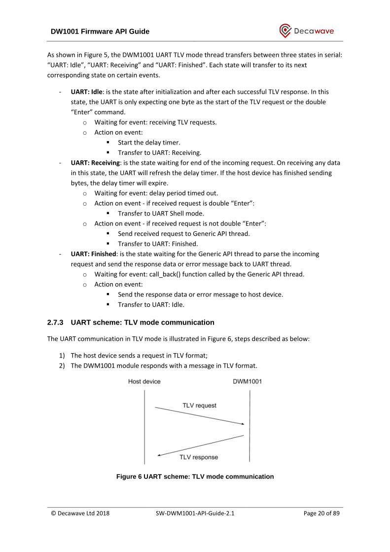
2.7.3 UART scheme: TLV mode communication
The UART communication in TLV mode is illustrated in Figure 6, steps described as below:
1) The host device sends a request in TLV format;
2) The DWM1001 module responds with a message in TLV format.
Figure 6 UART scheme: TLV mode communication

DW1001 Firmware API Guide
© Decawave Ltd 2018 SW-DWM1001-API-Guide-2.1 Page 21 of 89
2.7.4 UART example: TLV mode communication
Figure 7 illustrates an example of host device sending the dwm_gpio_cfg_output command to set
pin 13 level HIGH ([0x28, 0x02, 0x0D, 0x01] in byte array, detailed in Section 4.3.14) and receiving
the response from the DWM1001 module using the UART API in TLV mode. The steps of the
communication flow are:
1) The host device sends the dwm_gpio_cfg_output command in TLV format:
Type = 0x28, Length = 0x02, Value = 0x0D 0x01.
2) The DWM1001 module responds in TLV format:
Type = 0x40, Length = 0x01, value = 0x00,
where Type = 0x40 indicates this is a return message (see Section 6), Length = 0x01 indicates
that there is one byte following as data, value = 0x00 indicates the TLV request is parsed
correctly.
Figure 7 UART example: TLV mode communication
2.7.5 UART scheme: Shell mode communication
UART Shell mode provides prompt and uses Shell commands. The UART Shell mode intends to
provide users with human readable access to the APIs, thus, all Shell commands are strings of letters
followed by a character return, i.e. “Enter”. Users can input the string directly through keyboard and
press “Enter” to send the Shell commands. DWM1001 UART stays in the Shell mode after each Shell
commands except for the “quit” command.
As illustrated in Figure 8, a full Shell command communication flow includes the following steps:
1) Host device sends the Shell command + “Enter” to the DWM1001.
2) If there’s any message to respond, the DWM1001 sends the message to the host device.
3) If there’s nothing to respond, the DWM1001 doesn’t send anything and keeps quiet.

DW1001 Firmware API Guide
© Decawave Ltd 2018 SW-DWM1001-API-Guide-2.1 Page 22 of 89
Figure 8 UART scheme: Shell mode communication
2.7.6 UART example: Shell Mode communication
Figure 9 illustrates an example of host device sending the “GPIO set” command using UART Shell to
set pin 13 level HIGH (“gs 13” in byte array, followed by “Enter” key, detailed in Section 5.2.3). The
steps of the communication flow are:
1) The host device sends the “GPIO set” command in Shell mode: “gs 13” + “Enter”.
2) The DWM1001 responds the host with string “gpio13: 1”.
Figure 9 UART example: Shell mode communication
2.8 GPIO Scheme: DWM1001 notifies for status change
Rather than the host device initiating the SPI/UART communication, the DWM1001 module can send
notifications of status change by toggling the dedicated GPIO pin (P0.26) to HIGH level, as illustrated
in Figure 10. To enable this feature, host device needs to use the dwm_int_cfg command, detailed in
Section 4.3.14. On detecting the HIGH level, host device can initiate a dwm_status_get command,
detailed in Section 4.3.23, to get the status from the DWM1001 device. Both dwm_int_cfg and
dwm_status_get commands can be sent through SPI or UART schemes introduced in the previous
sections.

DW1001 Firmware API Guide
© Decawave Ltd 2018 SW-DWM1001-API-Guide-2.1 Page 23 of 89
Figure 10 GPIO scheme: DWM1001 notifies host device of status change, using GPIO
This GPIO pin level change will be postponed if the status change happens during the SPI TLV
request/response procedure described above to avoid conflict. In detail, when the SPI is in status:
“SPI: Wait for call_back”, “SPI: Wait for Read SIZE” and “SPI: Wait for Read DATA/ERR”, the GPIO
scheme will surrender the control of the GPIO pin. After the SPI communication when the SPI is in
status “SPI: Idle”, the GPIO scheme will regain the control of the GPIO pin.
2.9 API for on-board C code developers
Decawave provides the DWM1001 source pack of the pre-built firmware. Users can add their own
code and make use of the C code API functions in certain entry files provided in the source pack. In
this way, users are able to add their own functions inside the module firmware and perhaps not
need to add an external host controller device. The detail of adding such user code is provided in
DWM1001 Firmware User Guide [3].
A few points the C code users should note when using the on-board firmware:
1) User application is based on eCos RTOS and DWM libraries.
2) Files used for linking with the user applications:
a. dwm.h - header file - wrapper for all header files necessary for building of the user
application
b. libdwm.a - static library
c. extras.o, vectors.o, libtarget.a - eCos static library
d. target_s132_fw1.ld - linker script for firmware section 1
e. target_s132_fw2.ld - linker script for firmware section 2
3) The API provides functions and defines to the user application
a. Common functions on operating systems like thread creation, memory allocation,
access to interfaces (e.g. GPIO, SPI), synchronization (e.g. mutex, signal)
b. Initialization, configuration and maintenance of the DWM communication stack
c. Register of callbacks for incoming data and measurements

DW1001 Firmware API Guide
© Decawave Ltd 2018 SW-DWM1001-API-Guide-2.1 Page 24 of 89
3 GENERIC API INFORMATION
3.1 Used terminology
Anchor: has a fixed location – as a reference point to locate Tags. The module may be configured to
behave as an anchor node. An anchor initiator is an anchor with the initiator flag enabled as
introduced in section 3.4.8. It is a special anchor node that initiates the whole network, see the
system overview for more detail [4].
Tag: usually moving/changing location, determines its position dynamically with the help of the
anchors. The module may be configured to behave as a tag node.
Gateway: knows about all nodes in the network, provides status information about network nodes
(read/inspect), cache this information and provide it to gateway client, provides means to interact
with network elements (a.k.a. interaction proxy).
Node: network node (anchor, tag, gateway...)
LE: location engine – position solver function (on the tag)
3.2 Little endian
The integers used in the PANS API are little endian, unless otherwise stated.
3.3 Firmware update
As introduced in the DWM1001 System Overview [4], the nodes will compare their firmware version
to the network they want to join. If the firmware version is different, the nodes will try to update
their firmware before joining. This firmware update function can be enabled/disabled in the
configuration. Here lists the rules of the function that the nodes will follow.
Tag:
When enabled, the tag will always check the firmware version and try to synchronise its firmware
version with the network by sending the update request to the nearby anchor nodes in the network
before it starts ranging.
When disabled, the tag will start ranging without checking the firmware version. This can lead to
version compatibility problems and must be dealt with very carefully.
Anchor:
When enabled, before joining the network, the anchor will check the firmware version and try to
synchronise its firmware version with the network by sending the update request to the nearby
anchor nodes. After having joined the network, the anchor will respond to nearby nodes’ requests to
update their firmware.
When disabled, before joining the network, the anchor will directly send the join request and will
not check the firmware version. This can lead to version compatibility problems and must be dealt

DW1001 Firmware API Guide
© Decawave Ltd 2018 SW-DWM1001-API-Guide-2.1 Page 25 of 89
with very carefully. After having joined the network, the anchor will ignore the firmware update
requests from the nearby nodes.
3.4 Frequently used TLV values
Below lists the data that are frequently used in the APIs, either as input parameters or output
parameters. These parameters are of fixed size and some have their own value ranges.
3.4.1 err_code
1-byte error code, response information to the incoming requests.
err_code : 8-bit integer, valid values: 0 : OK 1 : unknown command or broken TLV frame 2 : internal error 3 : invalid parameter 4 : busy
3.4.2 position
13-byte position information of the node (anchor or tag).
position = x, y, z, qf : bytes 0-12, position coordinates and quality factor
x : bytes 0-3, 32-bit integer, in millimeters
y : bytes 4-7, 32-bit integer, in millimeters
z : bytes 8-11, 32-bit integer, in millimeters
qf : bytes 12, 8-bit integer, position quality factor in percent
3.4.3 gpio_idx
1-byte index of GPIO pins available to the user.
gpio_idx : 8-bit integer, valid values: 2, 8, 9, 10, 12, 13, 14, 15, 22, 23, 27, 30, 31.
Note: some GPIO pins are occupied by the PANS library and can only be accessed/controlled by
through the APIs partially:
- When configured as tag and BLE function is enabled, GPIO2 is occupied.
- When LED function is enabled, GPIO 22, 30 and 31 are occupied.
- During the module reboot, the bootloader (as part of the firmware image) blinks twice the
LEDs on GPIOs 22, 30 and 31 to indicate the module has restarted. Thus these GPIOs should
be used with care during the first 1s of a reboot operation.
3.4.4 gpio_value
1-byte value of the GPIO pin.
gpio_value = 8-bit integer, valid values:
DW1001 Firmware API Guide
© Decawave Ltd 2018 SW-DWM1001-API-Guide-2.1 Page 26 of 89
0 : set the I/O port pin to a LOW voltage, logic 0 value
1 : set the I/O port pin to a HIGH voltage, logic 1 value
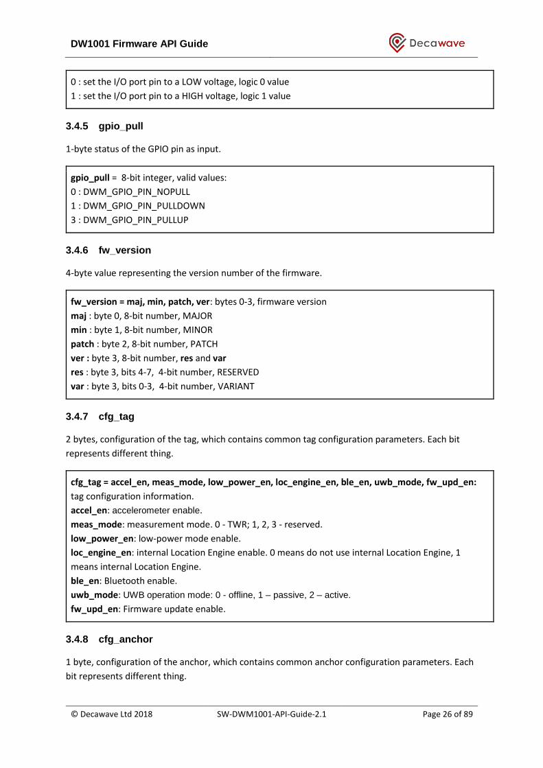
3.4.5 gpio_pull
1-byte status of the GPIO pin as input.
gpio_pull = 8-bit integer, valid values:
0 : DWM_GPIO_PIN_NOPULL
1 : DWM_GPIO_PIN_PULLDOWN
3 : DWM_GPIO_PIN_PULLUP
3.4.6 fw_version
4-byte value representing the version number of the firmware.
fw_version = maj, min, patch, ver: bytes 0-3, firmware version
maj : byte 0, 8-bit number, MAJOR
min : byte 1, 8-bit number, MINOR
patch : byte 2, 8-bit number, PATCH
ver : byte 3, 8-bit number, res and var
res : byte 3, bits 4-7, 4-bit number, RESERVED
var : byte 3, bits 0-3, 4-bit number, VARIANT
3.4.7 cfg_tag
2 bytes, configuration of the tag, which contains common tag configuration parameters. Each bit
represents different thing.
cfg_tag = accel_en, meas_mode, low_power_en, loc_engine_en, ble_en, uwb_mode, fw_upd_en:
tag configuration information.
accel_en: accelerometer enable.
meas_mode: measurement mode. 0 - TWR; 1, 2, 3 - reserved.
low_power_en: low-power mode enable.
loc_engine_en: internal Location Engine enable. 0 means do not use internal Location Engine, 1
means internal Location Engine.
ble_en: Bluetooth enable.
uwb_mode: UWB operation mode: 0 - offline, 1 – passive, 2 – active.
fw_upd_en: Firmware update enable.
3.4.8 cfg_anchor
1 byte, configuration of the anchor, which contains common anchor configuration parameters. Each
bit represents different thing.

DW1001 Firmware API Guide
© Decawave Ltd 2018 SW-DWM1001-API-Guide-2.1 Page 27 of 89
cfg_anchor = initiator, bridge, ble_en, uwb_mode, fw_upd_en
initiator : Initiator role enable.
bridge : Bridge role enable.
ble_en : Bluetooth enable.
uwb_mode: UWB operation mode: 0 - offline, 1 – passive, 2 – active.
fw_upd_en : Firmware update enable.
3.4.9 cfg_node
2 bytes, configuration of the node, which contains common configuration parameters. Each bit
represents different thing.
cfg_anchor = err_code, mode, initiator, bridge, low_power_en, meas_mode, loc_engine_en, ble_en,
uwb_mode, fw_update_en
mode: 0 - tag, 1 - anchor.
initiator : Initiator role enable.
bridge : Bridge role enable.
accel_en: accelerometer enable.
meas_mode: measurement mode. 0 - TWR; 1, 2, 3 - reserved.
low_power_en: low-power mode enable.
loc_engine_en: internal Location Engine enable. 0 means do not use internal Location Engine, 1
means internal Location Engine is active.
ble_en: Bluetooth enable.
uwb_mode: UWB operation mode: 0 - offline, 1 – passive, 2 – active.
fw_upd_en: Firmware update enable.

DW1001 Firmware API Guide
© Decawave Ltd 2018 SW-DWM1001-API-Guide-2.1 Page 28 of 89
4 API FUNCTION DESCRIPTIONS
4.1 List of API functions
The API functions for on-board user app (c code) and SPI/UART TLV commands are unified. Listed
below in Table 2, in TLV type ascending order.
Table 2 API request function list
API function name Onboard user app available
SPI/UART TLV Ref (Section)
type Length
dwm_pos_set y 0x01 0x0d 4.3.1
dwm_pos_get y 0x02 0x00 4.3.2
dwm_upd_rate_set y 0x03 0x02 4.3.3
dwm_upd_rate_get y 0x04 0x00 4.3.4
dwm_cfg_tag_set y 0x05 0x02 4.3.5
dwm_cfg_anchor_set y 0x07 0x01 4.3.6
dwm_cfg_get y 0x08 0x00 4.3.7
dwm_sleep y 0x0a 0x00 4.3.8
dwm_loc_get y 0x0c 0x00 4.3.9
dwm_baddr_set y 0x0f 0x00 4.3.10
dwm_baddr_get y 0x10 0x00 4.3.11
dwm_reset y 0x14 0x00 4.3.12
dwm_ver_get y 0x15 0x00 4.3.13
dwm_usr_data_read y 0x19 0x00 4.3.14
dwm_usr_data_write y 0x1a 0x22 4.3.15
dwm_label_read y 0x1c 0x00 4.3.16
dwm_label_write y 0x1d 0x10 4.3.17
dwm_gpio_cfg_output y 0x28 0x02 4.3.18
dwm_gpio_cfg_input y 0x29 0x02 4.3.19
dwm_gpio_value_set y 0x2a 0x02 4.3.20
dwm_gpio_value_get y 0x2b 0x01 4.3.21
dwm_gpio_value_toggle y 0x2c 0x01 4.3.22
dwm_panid_set y 0x2e 0x02 4.3.23
dwm_panid_get y 0x2f 0x00 4.3.24
dwm_node_id_get y 0x30 0x00 4.3.25
dwm_status_get n 0x32 0x00 4.3.26
dwm_int_cfg_set n 0x34 0x01 4.3.27
dwm_int_cfg_get n 0x35 0x00 4.3.28
dwm_bh_status_get n 0x3a 0x00 4.3.29
dwm_sec_key_set y 0x3c 0x10 4.3.30
dwm_gpio_irq_cfg y n/a n/a 4.3.31
dwm_gpio_irq_dis y n/a n/a 4.3.32
dwm_i2c_read y n/a n/a 4.3.33
dwm_i2c_write y n/a n/a 4.3.34

DW1001 Firmware API Guide
© Decawave Ltd 2018 SW-DWM1001-API-Guide-2.1 Page 29 of 89
dwm_evt_cb_register y n/a n/a 4.3.35
dwm_evt_wait y n/a n/a 4.3.36
The definition and usage of the API functions are described below in individual sub-sections. In
introducing each API function, all possible accesses are described, including c code, UART/SPI TLV.
Note: Some API functions are only provided in limited accesses.
Note: There are more TLV type than listed in Table 2. The TLV types that do not relate to API
functions are not introduced here, e.g. the TLV response types. See Section 6 for the full TLV type
list.
4.2 Usage of the APIs
Examples of how the UART Generic, SPI and C code API can be used is introduced in the DWM1001
Firmware User Guide [3]. The examples intend to give a brief view of the API usage and only include
very simple API functions. The code in the source files of the examples can be changed to
modify/add functionalities. The full list of API functions as shown in Table 2 can also be found in the
included header files of the API source code packages. Table 3 lists the packages with examples of
the corresponding APIs, the locations of the header files and the locations of the source files.
Table 3 API examples location
API Package with examples
Header file location Example source file location
C code DWM1001 on-
board package [5]
dwm\include\dwm
.h
dwm\examples\dwm-simple\dwm-simple.c
UART
Generic
DWM1001 Host
API package [6]
include\dwm_api.h examples\ex1_TWR_2Hosts\tag\tag_cfg.c
SPI DWM1001 Host
API package [6]
include\dwm_api.h examples\ex1_TWR_2Hosts\tag\tag_cfg.c
4.3 Details of the API functions
The details of each API function listed in Table 2 are described in the below sub-sections.
DW1001 Firmware API Guide
© Decawave Ltd 2018 SW-DWM1001-API-Guide-2.1 Page 30 of 89
4.3.1 dwm_pos_set
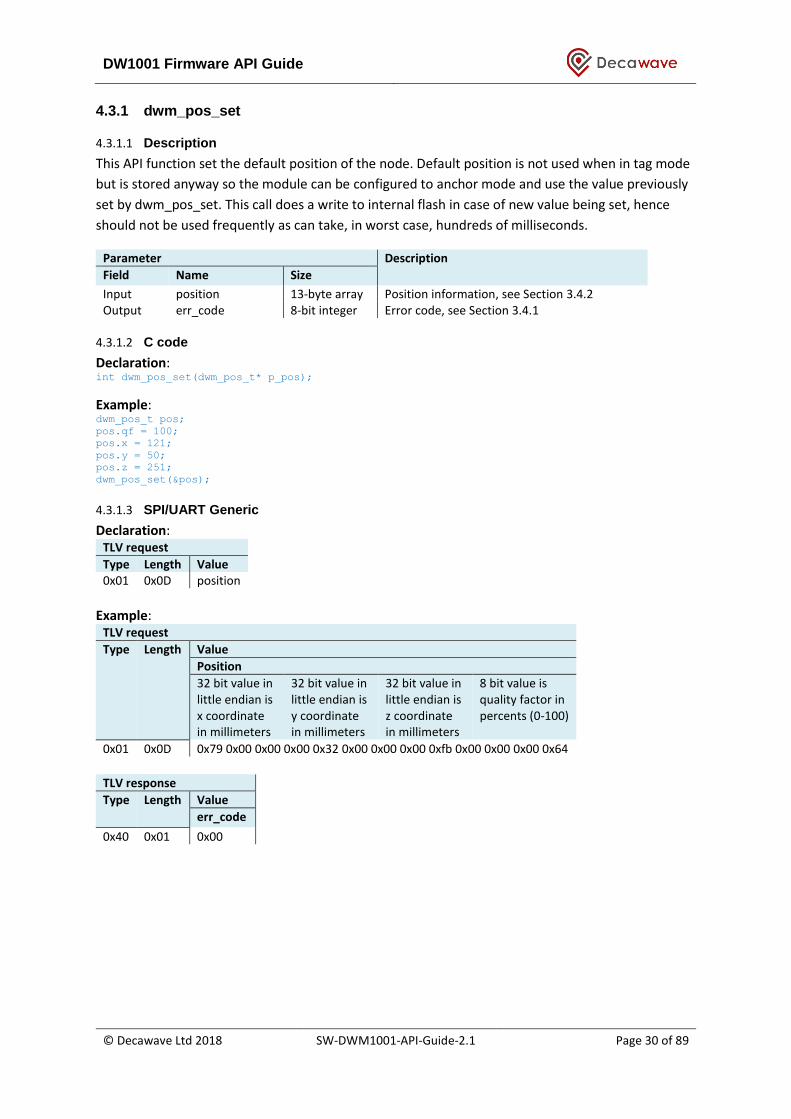
4.3.1.1 Description
This API function set the default position of the node. Default position is not used when in tag mode
but is stored anyway so the module can be configured to anchor mode and use the value previously
set by dwm_pos_set. This call does a write to internal flash in case of new value being set, hence
should not be used frequently as can take, in worst case, hundreds of milliseconds.
Parameter Description
Field Name Size
Input position 13-byte array Position information, see Section 3.4.2 Output err_code 8-bit integer Error code, see Section 3.4.1
4.3.1.2 C code
Declaration: int dwm_pos_set(dwm_pos_t* p_pos);
Example: dwm_pos_t pos;
pos.qf = 100;
pos.x = 121;
pos.y = 50;
pos.z = 251;
dwm_pos_set(&pos);
4.3.1.3 SPI/UART Generic
Declaration: TLV request
Type Length Value 0x01 0x0D position
Example:
TLV request
Type Length Value
Position
32 bit value in little endian is x coordinate in millimeters
32 bit value in little endian is y coordinate in millimeters
32 bit value in little endian is z coordinate in millimeters
8 bit value is quality factor in percents (0-100)
0x01 0x0D 0x79 0x00 0x00 0x00 0x32 0x00 0x00 0x00 0xfb 0x00 0x00 0x00 0x64
TLV response
Type Length Value
err_code
0x40 0x01 0x00
DW1001 Firmware API Guide
© Decawave Ltd 2018 SW-DWM1001-API-Guide-2.1 Page 31 of 89
4.3.2 dwm_pos_get
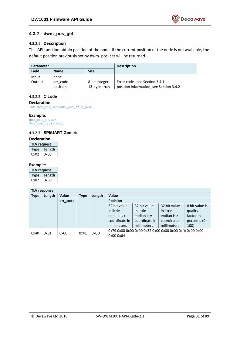
4.3.2.1 Description
This API function obtain position of the node. If the current position of the node is not available, the
default position previously set by dwm_pos_set will be returned.
Parameter Description
Field Name Size
Input none Output err_code 8-bit integer Error code, see Section 3.4.1
position 13-byte array position information, see Section 3.4.2
4.3.2.2 C code
Declaration: int dwm_pos_set(dwm_pos_t* p_pos);
Example: dwm_pos_t pos;
dwm_pos_get(&pos);
4.3.2.3 SPI/UART Generic
Declaration: TLV request
Type Length 0x02 0x00
Example:
TLV request
Type Length 0x02 0x00
TLV response
Type Length Value Type Length Value
err_code Position
32 bit value in little endian is x coordinate in millimeters
32 bit value in little endian is y coordinate in millimeters
32 bit value in little endian is z coordinate in millimeters
8 bit value is quality factor in percents (0-100)
0x40 0x01 0x00 0x41 0x0D 0x79 0x00 0x00 0x00 0x32 0x00 0x00 0x00 0xfb 0x00 0x00 0x00 0x64

DW1001 Firmware API Guide
© Decawave Ltd 2018 SW-DWM1001-API-Guide-2.1 Page 32 of 89
4.3.3 dwm_upd_rate_set
4.3.3.1 Description
This API function sets the update rate and the stationary update rate of the position in unit of 100
milliseconds. Stationary update rate must be greater or equal to normal update rate. This call does a
write to the internal flash in case of new value being set, hence should not be used frequently as can
take, in worst case, hundreds of milliseconds.
Parameter Description
Field Name Size
Input update_rate 16-bit integer position publication interval in multiples of 100 milliseconds
update_rate_stationary 16-bit integer position publication interval when node is not moving in multiples of 100 milliseconds, maximum is 2 minutes, must be greater or equal to normal update_rate
Output err_code 8-bit integer Error code, see Section 3.4.1
4.3.3.2 C code
Declaration: int dwm_upd_rate_set(uint16_t ur, uint16 urs);
Example: dwm_upd_rate_set(10, 50); // update rate 1 second. 5 seconds stationary
4.3.3.3 SPI/UART Generic
Declaration: TLV request
Type Length Value 0x03 0x04 update_rate update_rate_stationary
Example:
TLV request
Type Length Value
update_rate update_rate_stationary
16 bit value in little endian, which is update rate in multiples of 100 ms (e.g. 0x0A 0x00 means 10)
16 bit value in little endian, which is stationary update rate in multiples of 100 ms. E.g. 0x0A 0x00 means 5.0.
0x03 0x04 0x0A 0x00 0x32 0x00
TLV response
Type Length Value
err_code
0x40 0x01 0x00

DW1001 Firmware API Guide
© Decawave Ltd 2018 SW-DWM1001-API-Guide-2.1 Page 33 of 89
4.3.4 dwm_upd_rate_get
4.3.4.1 Description
This API function gets position update rate.
Parameter Description
Field Name Size
Input none Output err_code 8-bit integer Error code, see Section 3.4.1
update_rate 16-bit integer position update interval in multiples of 100 milliseconds,
update_rate_stationary 16-bit integer Stationary position update interval in multiples of 100 milliseconds
4.3.4.2 C code
Declaration: int dwm_upd_rate_get(uint16_t* p_ur, uint16_t* p_urs);
Example: uint16_t ur, urs;
dwm_upd_rate_get(&ur, &urs);
4.3.4.3 SPI/UART Generic
Declaration: TLV request
Type Length 0x04 0x00
Example:
TLV request
Type Length 0x04 0x00
TLV response
Type Length Value Type Length Value
err_code update_rate, first 2 bytes, indicating the position update interval in multiples of 100 ms. E.g. 0x0A 0x00 means 1.0s interval.
update_rate_stationary, second 2 bytes, indicating the stationary position update interval in multiples of 100 ms. E.g. 0x32 0x00 means 5.0s interval.
0x40 0x01 0x00 0x45 0x04 0x0A 0x00 0x32 0x00
DW1001 Firmware API Guide
© Decawave Ltd 2018 SW-DWM1001-API-Guide-2.1 Page 34 of 89
4.3.5 dwm_cfg_tag_set
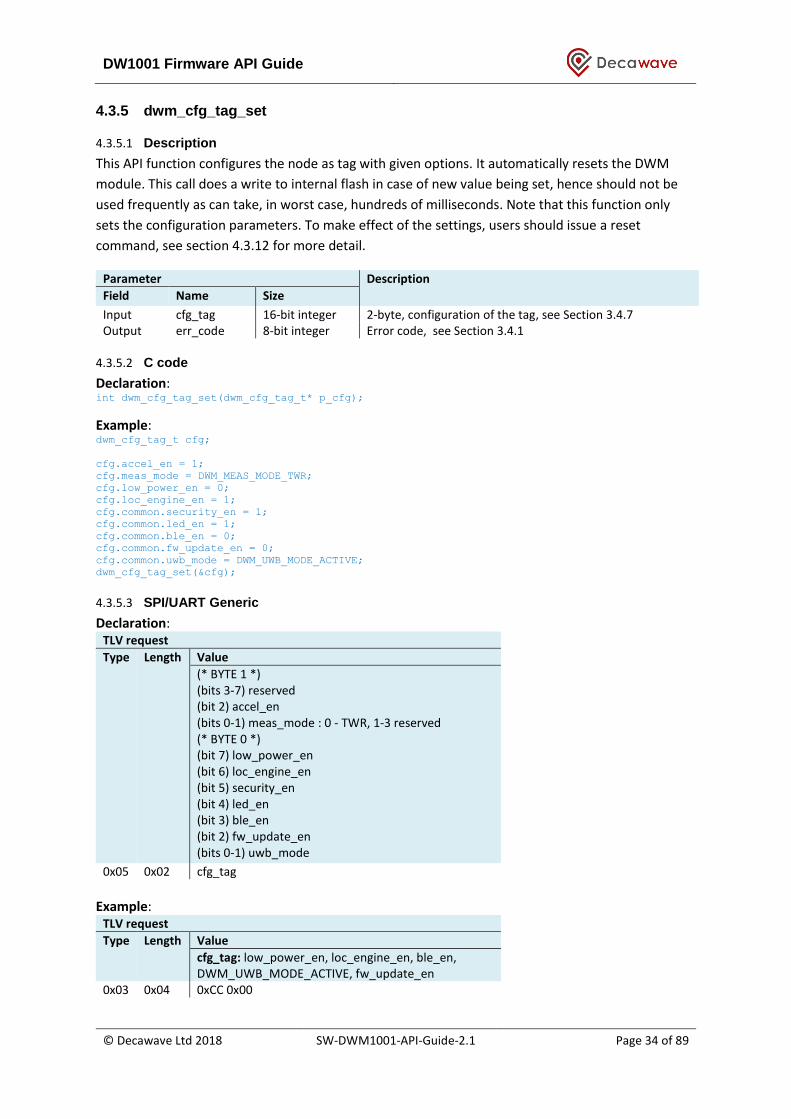
4.3.5.1 Description
This API function configures the node as tag with given options. It automatically resets the DWM
module. This call does a write to internal flash in case of new value being set, hence should not be
used frequently as can take, in worst case, hundreds of milliseconds. Note that this function only
sets the configuration parameters. To make effect of the settings, users should issue a reset
command, see section 4.3.12 for more detail.
Parameter Description
Field Name Size
Input cfg_tag 16-bit integer 2-byte, configuration of the tag, see Section 3.4.7 Output err_code 8-bit integer Error code, see Section 3.4.1
4.3.5.2 C code
Declaration: int dwm_cfg_tag_set(dwm_cfg_tag_t* p_cfg);
Example: dwm_cfg_tag_t cfg;
cfg.accel_en = 1;
cfg.meas_mode = DWM_MEAS_MODE_TWR;
cfg.low_power_en = 0;
cfg.loc_engine_en = 1;
cfg.common.security_en = 1;
cfg.common.led_en = 1;
cfg.common.ble_en = 0;
cfg.common.fw_update_en = 0;
cfg.common.uwb_mode = DWM_UWB_MODE_ACTIVE;
dwm_cfg_tag_set(&cfg);
4.3.5.3 SPI/UART Generic
Declaration: TLV request
Type Length Value
(* BYTE 1 *) (bits 3-7) reserved (bit 2) accel_en (bits 0-1) meas_mode : 0 - TWR, 1-3 reserved (* BYTE 0 *) (bit 7) low_power_en (bit 6) loc_engine_en (bit 5) security_en (bit 4) led_en (bit 3) ble_en (bit 2) fw_update_en (bits 0-1) uwb_mode
0x05 0x02 cfg_tag
Example:
TLV request
Type Length Value
cfg_tag: low_power_en, loc_engine_en, ble_en, DWM_UWB_MODE_ACTIVE, fw_update_en
0x03 0x04 0xCC 0x00

DW1001 Firmware API Guide
© Decawave Ltd 2018 SW-DWM1001-API-Guide-2.1 Page 35 of 89
TLV response
Type Length Value
err_code
0x40 0x01 0x00

DW1001 Firmware API Guide
© Decawave Ltd 2018 SW-DWM1001-API-Guide-2.1 Page 36 of 89
4.3.6 dwm_cfg_anchor_set
4.3.6.1 Description
This API function configures the node as tag with given options. It automatically resets the DWM
module. This call does a write to internal flash in case of new value being set, hence should not be
used frequently as can take, in worst case, hundreds of milliseconds. Note that this function only
sets the configuration parameters. To make effect of the settings, users should issue a reset
command, see section 4.3.12 for more detail.
Parameter Description
Field Name Size
Input cfg_anchor 8-bit integer 1-byte, configuration of the tag, see Section 3.4.8 Output err_code 8-bit integer Error code, see Section 3.4.1
4.3.6.2 C code
Declaration: int dwm_cfg_anchor_set(dwm_cfg_anchor_t* p_cfg)
Example: dwm_cfg_anchor_t cfg;
cfg.initiator = 1;
cfg.bridge = 0;
cfg.common.security_en = 0;
cfg.common.led_en = 1;
cfg.common.ble_en = 1;
cfg.common.fw_update_en = 1;
cfg.common.uwb_mode = DWM_UWB_MODE_ACTIVE;
dwm_cfg_anchor_set(&cfg);
4.3.6.3 SPI/UART Generic
Declaration: TLV request
Type Length Value
(bit 7) initiator (bit 6) bridge (bit 5) security_en (bit 4) led_en (bit 3) ble_en (bit 2) fw_update_en (bits 0-1) uwb_mode
0x07 0x01 cfg_anchor
Example:
TLV request
Type Length Value
cfg_anchor: initiator, ble_en, fw_update_en,
UWB_MODE_ACTIVE
0x03 0x04 0x8E
TLV response
Type Length Value
err_code
0x40 0x01 0x00
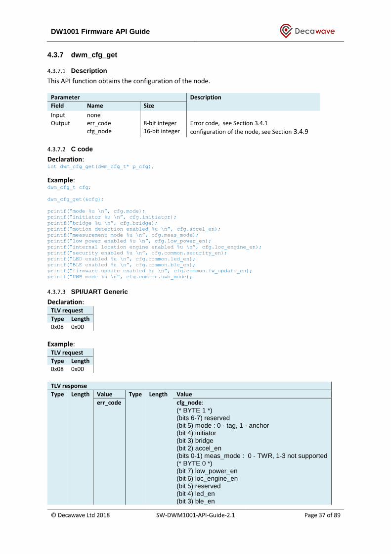
DW1001 Firmware API Guide
© Decawave Ltd 2018 SW-DWM1001-API-Guide-2.1 Page 37 of 89
4.3.7 dwm_cfg_get
4.3.7.1 Description
This API function obtains the configuration of the node.
Parameter Description
Field Name Size
Input none Output err_code 8-bit integer Error code, see Section 3.4.1
cfg_node 16-bit integer configuration of the node, see Section 3.4.9
4.3.7.2 C code
Declaration: int dwm_cfg_get(dwm_cfg_t* p_cfg);
Example: dwm_cfg_t cfg;
dwm_cfg_get(&cfg);
printf(“mode %u \n”, cfg.mode);
printf(“initiator %u \n”, cfg.initiator);
printf(“bridge %u \n”, cfg.bridge);
printf(“motion detection enabled %u \n”, cfg.accel_en);
printf(“measurement mode %u \n”, cfg.meas_mode);
printf(“low power enabled %u \n”, cfg.low_power_en);
printf(“internal location engine enabled %u \n”, cfg.loc_engine_en);
printf(“security enabled %u \n”, cfg.common.security_en);
printf(“LED enabled %u \n”, cfg.common.led_en);
printf(“BLE enabled %u \n”, cfg.common.ble_en);
printf(“firmware update enabled %u \n”, cfg.common.fw_update_en);
printf(“UWB mode %u \n”, cfg.common.uwb_mode);
4.3.7.3 SPI/UART Generic
Declaration: TLV request
Type Length 0x08 0x00
Example:
TLV request
Type Length 0x08 0x00
TLV response
Type Length Value Type Length Value
err_code cfg_node: (* BYTE 1 *) (bits 6-7) reserved (bit 5) mode : 0 - tag, 1 - anchor (bit 4) initiator (bit 3) bridge (bit 2) accel_en (bits 0-1) meas_mode : 0 - TWR, 1-3 not supported (* BYTE 0 *) (bit 7) low_power_en (bit 6) loc_engine_en (bit 5) reserved (bit 4) led_en (bit 3) ble_en
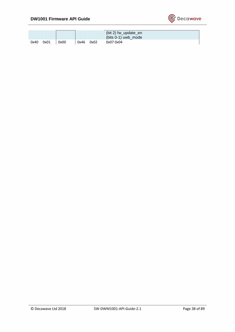
DW1001 Firmware API Guide
© Decawave Ltd 2018 SW-DWM1001-API-Guide-2.1 Page 38 of 89
(bit 2) fw_update_en (bits 0-1) uwb_mode
0x40 0x01 0x00 0x46 0x02 0x07 0x04
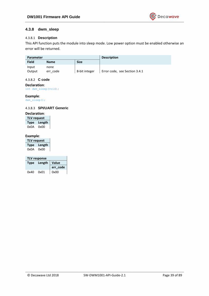
DW1001 Firmware API Guide
© Decawave Ltd 2018 SW-DWM1001-API-Guide-2.1 Page 39 of 89
4.3.8 dwm_sleep
4.3.8.1 Description
This API function puts the module into sleep mode. Low power option must be enabled otherwise an
error will be returned.
Parameter Description
Field Name Size
Input none Output err_code 8-bit integer Error code, see Section 3.4.1
4.3.8.2 C code
Declaration: int dwm_sleep(void);
Example: dwm_sleep();
4.3.8.3 SPI/UART Generic
Declaration: TLV request
Type Length 0x0A 0x00
Example:
TLV request
Type Length 0x0A 0x00
TLV response
Type Length Value
err_code
0x40 0x01 0x00
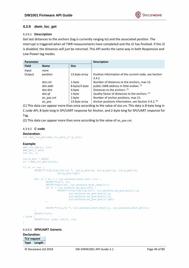
DW1001 Firmware API Guide
© Decawave Ltd 2018 SW-DWM1001-API-Guide-2.1 Page 40 of 89
4.3.9 dwm_loc_get
4.3.9.1 Description
Get last distances to the anchors (tag is currently ranging to) and the associated position. The
interrupt is triggered when all TWR measurements have completed and the LE has finished. If the LE
is disabled, the distances will just be returned. This API works the same way in both Responsive and
Low-Power tag modes.
Parameter Description
Field Name Size
Input none Output position 13-byte array Position information of the current node, see Section
3.4.2 dist.cnt 1-byte Number of distances to the anchors, max 15. dist.addr 8-byte/2-byte public UWB address in little endian. (1) dist.dist 4-byte Distances to the anchors. (1) dist.qf 1-byte Quality factor of distances to the anchors. (1) an_pos.cnt 1-byte Number of anchor positions, max 15. an_pos 13-byte array Anchor positions information, see Section 3.4.2. (2)
(1) This data can appear more than once according to the value of dist.cnt. This data is 8-byte long in
C code API, 8-byte long in SPI/UART response for Anchor, and 2-byte long for SPI/UART response for
Tag.
(2) This data can appear more than once according to the value of an_pos.cnt.
4.3.9.2 C code
Declaration: int dwm_loc_get(dwm_loc_data_t* p_loc);
Example: dwm_loc_data_t loc;
dwm_pos_t pos;
int rv, i;
loc.p_pos = &pos;
rv = dwm_loc_get(&loc);
if (0 == rv) {
PRINT("[%ld,%ld,%ld,%u] ", loc.p_pos->x, loc.p_pos->y, loc.p_pos->z,
loc.p_pos->qf);
for (i = 0; i < loc.anchors.dist.cnt; ++i) {
PRINT("%u)", i);
PRINT("0x%llx", loc.anchors.dist.addr[i]);
if (i < loc.anchors.an_pos.cnt) {
PRINT("[%ld,%ld,%ld,%u]", loc.anchors.an_pos.pos[i].x,
loc.anchors.an_pos.pos[i].y,
loc.anchors.an_pos.pos[i].z,
loc.anchors.an_pos.pos[i].qf);
}
PRINT("=%lu,%u ", loc.anchors.dist.dist[i], loc.anchors.dist.qf[i]);
}
PRINT("\n");
} else {
PRINT("err code: %d\n", rv);
}
4.3.9.3 SPI/UART Generic
Declaration: TLV request
Type Length
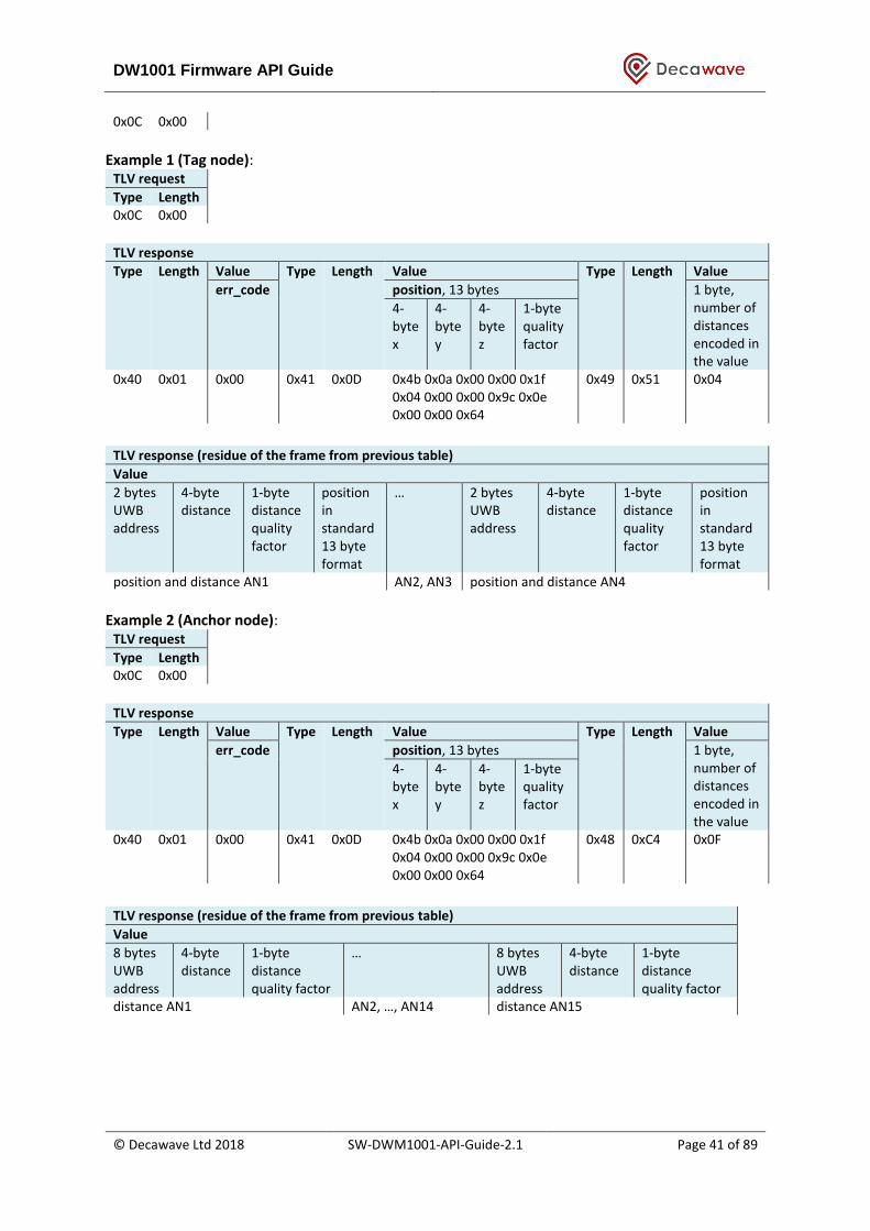
DW1001 Firmware API Guide
© Decawave Ltd 2018 SW-DWM1001-API-Guide-2.1 Page 41 of 89
0x0C 0x00
Example 1 (Tag node):
TLV request
Type Length 0x0C 0x00
TLV response
Type Length Value Type Length Value Type Length Value
err_code position, 13 bytes 1 byte, number of distances encoded in the value
4-byte x
4-byte y
4-byte z
1-byte quality factor
0x40 0x01 0x00 0x41 0x0D 0x4b 0x0a 0x00 0x00 0x1f 0x04 0x00 0x00 0x9c 0x0e 0x00 0x00 0x64
0x49 0x51 0x04
TLV response (residue of the frame from previous table)
Value
2 bytes UWB address
4-byte distance
1-byte distance quality factor
position in standard 13 byte format
…
2 bytes UWB address
4-byte distance
1-byte distance quality factor
position in standard 13 byte format
position and distance AN1 AN2, AN3 position and distance AN4
Example 2 (Anchor node):
TLV request
Type Length 0x0C 0x00
TLV response
Type Length Value Type Length Value Type Length Value
err_code position, 13 bytes 1 byte, number of distances encoded in the value
4-byte x
4-byte y
4-byte z
1-byte quality factor
0x40 0x01 0x00 0x41 0x0D 0x4b 0x0a 0x00 0x00 0x1f 0x04 0x00 0x00 0x9c 0x0e 0x00 0x00 0x64
0x48 0xC4 0x0F
TLV response (residue of the frame from previous table)
Value
8 bytes UWB address
4-byte distance
1-byte distance quality factor
…
8 bytes UWB address
4-byte distance
1-byte distance quality factor
distance AN1 AN2, …, AN14 distance AN15
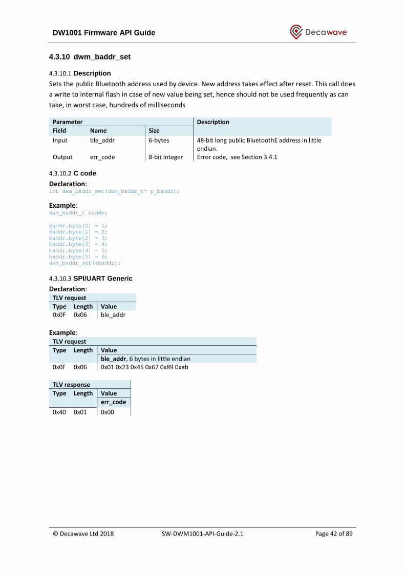
DW1001 Firmware API Guide
© Decawave Ltd 2018 SW-DWM1001-API-Guide-2.1 Page 42 of 89
4.3.10 dwm_baddr_set
4.3.10.1 Description
Sets the public Bluetooth address used by device. New address takes effect after reset. This call does
a write to internal flash in case of new value being set, hence should not be used frequently as can
take, in worst case, hundreds of milliseconds
Parameter Description
Field Name Size
Input ble_addr 6-bytes 48-bit long public BluetoothE address in little endian.
Output err_code 8-bit integer Error code, see Section 3.4.1
4.3.10.2 C code
Declaration: int dwm_baddr_set(dwm_baddr_t* p_baddr);
Example: dwm_baddr_t baddr;
baddr.byte[0] = 1;
baddr.byte[1] = 2;
baddr.byte[2] = 3;
baddr.byte[3] = 4;
baddr.byte[4] = 5;
baddr.byte[5] = 6;
dwm_baddr_set(&baddr);
4.3.10.3 SPI/UART Generic
Declaration: TLV request
Type Length Value 0x0F 0x06 ble_addr
Example:
TLV request
Type Length Value
ble_addr, 6 bytes in little endian
0x0F 0x06 0x01 0x23 0x45 0x67 0x89 0xab
TLV response
Type Length Value
err_code
0x40 0x01 0x00

DW1001 Firmware API Guide
© Decawave Ltd 2018 SW-DWM1001-API-Guide-2.1 Page 43 of 89
4.3.11 dwm_baddr_get
4.3.11.1 Description
Get Bluetooth address currently used by device.
Parameter Description
Field Name Size
Input none Output ble_addr 6-bytes 48-bit long public Bluetooth address in little
endian.
4.3.11.2 C code
Declaration: int dwm_baddr_get(dwm_baddr_t* p_baddr);
Example: dwm_baddr_t baddr;
int i;
if (DWM_OK == dwm_baddr_get(&baddr)) {
printf("addr=");
for (i = DWM_BLE_ADDR_LEN - 1; i >= 0; --i) {
printf("%02x%s", baddr.byte[i], (i > 0) ? ":" : "");
}
printf("\n");
} else {
printf("FAILED");
}
4.3.11.3 SPI/UART Generic
Declaration: TLV request
Type Length 0x10 0x00
Example:
TLV request
Type Length 0x10 0x00
TLV response
Type Length Value Type Length Value
err_code ble_addr, 6 bytes in little endian 0x40 0x01 0x00 0x5F 0x06 0x01 0x23 0x45 0x67 0x89 0xab

DW1001 Firmware API Guide
© Decawave Ltd 2018 SW-DWM1001-API-Guide-2.1 Page 44 of 89
4.3.12 dwm_reset
4.3.12.1 Description
This API function reboots the module.
Parameter Description
Field Name Size
Input none Output err_code 8-bit integer Error code, see Section 3.4.1
4.3.12.2 C code
Declaration: int dwm_reset(void);
Example: dwm_reset();
4.3.12.3 SPI/UART Generic
Declaration: TLV request
Type Length 0x14 0x00
Example:
TLV request
Type Length 0x14 0x00
TLV response
Type Length Value
err_code
0x40 0x01 0x00

DW1001 Firmware API Guide
© Decawave Ltd 2018 SW-DWM1001-API-Guide-2.1 Page 45 of 89
4.3.13 dwm_ver_get
4.3.13.1 Description
This API function obtains the firmware version of the module.
Parameter Description
Field Name Size
Input none Output err_code 8-bit integer Error code, see Section 3.4.1
fw_version 4-byte array firmware version, see Section 3.4.6 cfg_version 4-byte array configuration version, 32-bits integer hw_version 4-byte array hardware version, 32-bits integer
4.3.13.2 C code
Declaration: int dwm_ver_get(dwm_ver_t* p_ver);
Example: dwm_ver_t ver;
dwm_ver_get(&ver);
4.3.13.3 SPI/UART Generic
Declaration: TLV request
Type Length 0x15 0x00
Example:
TLV request
Type Length 0x15 0x00
TLV response Type Length Value Type Length Value Type Length Value
err_code fw_version: maj = 1 min = 2 patch = 5 var = 1
cfg_version
0x40 0x01 0x00 0x50 0x04 0x01 0x05 0x02 0x01 0x51 0x04 0x00 0x07 0x01 0x00
TLV response (residue of the frame from previous table) Type Length Value hw_version
0x52 0x04 0x2a 0x00 0xca 0xde
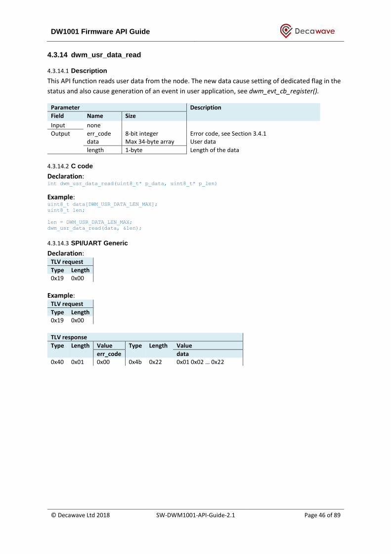
DW1001 Firmware API Guide
© Decawave Ltd 2018 SW-DWM1001-API-Guide-2.1 Page 46 of 89
4.3.14 dwm_usr_data_read
4.3.14.1 Description
This API function reads user data from the node. The new data cause setting of dedicated flag in the
status and also cause generation of an event in user application, see dwm_evt_cb_register().
Parameter Description
Field Name Size
Input none
Output err_code 8-bit integer Error code, see Section 3.4.1 data Max 34-byte array User data
length 1-byte Length of the data
4.3.14.2 C code
Declaration: int dwm_usr_data_read(uint8_t* p_data, uint8_t* p_len)
Example: uint8_t data[DWM_USR_DATA_LEN_MAX];
uint8_t len;
len = DWM_USR_DATA_LEN_MAX;
dwm_usr_data_read(data, &len);
4.3.14.3 SPI/UART Generic
Declaration: TLV request
Type Length 0x19 0x00
Example:
TLV request
Type Length 0x19 0x00
TLV response Type Length Value Type Length Value
err_code data 0x40 0x01 0x00 0x4b 0x22 0x01 0x02 … 0x22

DW1001 Firmware API Guide
© Decawave Ltd 2018 SW-DWM1001-API-Guide-2.1 Page 47 of 89
4.3.15 dwm_usr_data_write
4.3.15.1 Description
This API function writes user data to the network.
Parameter Description
Field Name Size
Input label Max 16-byte array The label
length 1-byte Length of the label Output err_code 8-bit integer Error code, see Section 3.4.1
4.3.15.2 C code
Declaration: int dwm_usr_data_write(uint8_t* p_data, uint8_t len, bool overwrite)
Example: uint8_t len, data[DWM_USR_DATA_LEN_MAX];
len = DWM_USR_DATA_LEN_MAX;
dwm_usr_data_write(data, len, false);
4.3.15.3 SPI/UART Generic
Declaration: TLV request
Type Length Value 0x1a 0x22 data
Example:
TLV request
Type Length Value
data, 34 bytes max
0x1a 0x22 0x01 0x02 … 0x22
TLV response
Type Length Value
err_code
0x40 0x01 0x00

DW1001 Firmware API Guide
© Decawave Ltd 2018 SW-DWM1001-API-Guide-2.1 Page 48 of 89
4.3.16 dwm_label_read
4.3.16.1 Description
This API function reads the node label.
Parameter Description
Field Name Size
Input none
Output err_code 8-bit integer Error code, see Section 3.4.1 label Max 16-byte array The label
length 1-byte Length of the label
4.3.16.2 C code
Declaration: int dwm_label_read(uint8_t* p_label, uint8_t* p_len)
Example: uint8_t label[DWM_LABEL_LEN_MAX];
uint8_t len;
len = DWM_USR_DATA_LEN_MAX;
dwm_label_read(label, &len);
4.3.16.3 SPI/UART Generic
Declaration: TLV request
Type Length 0x1c 0x00
Example:
TLV request
Type Length 0x1c 0x00
TLV response Type Length Value Type Length Value
err_code label 0x40 0x01 0x00 0x4c 0x10 0x01 0x02 … 0x10
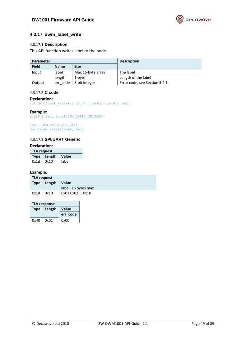
DW1001 Firmware API Guide
© Decawave Ltd 2018 SW-DWM1001-API-Guide-2.1 Page 49 of 89
4.3.17 dwm_label_write
4.3.17.1 Description
This API function writes label to the node.
Parameter Description
Field Name Size
Input label Max 16-byte array The label
length 1-byte Length of the label Output err_code 8-bit integer Error code, see Section 3.4.1
4.3.17.2 C code
Declaration: int dwm_label_write(uint8_t* p_label, uint8_t len);
Example: uint8_t len, label[DWM_LABEL_LEN_MAX];
len = DWM_LABEL_LEN_MAX;
dwm_label_write(label, len);
4.3.17.3 SPI/UART Generic
Declaration: TLV request
Type Length Value 0x1d 0x10 label
Example:
TLV request
Type Length Value
label, 16 bytes max
0x1d 0x10 0x01 0x02 … 0x10
TLV response
Type Length Value
err_code
0x40 0x01 0x00
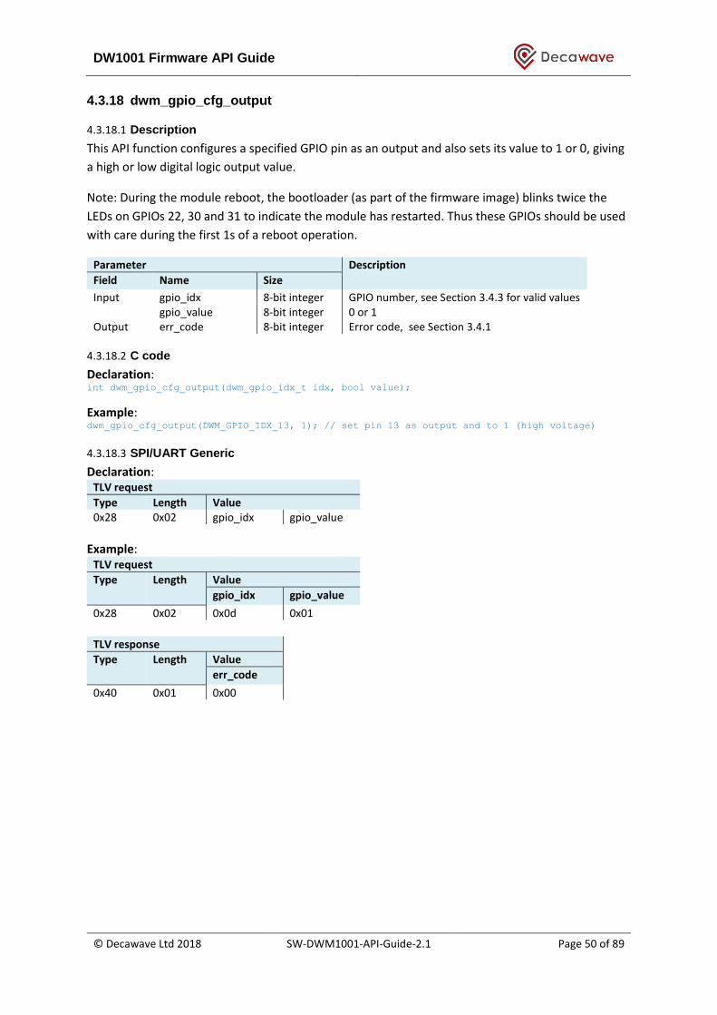
DW1001 Firmware API Guide
© Decawave Ltd 2018 SW-DWM1001-API-Guide-2.1 Page 50 of 89
4.3.18 dwm_gpio_cfg_output
4.3.18.1 Description
This API function configures a specified GPIO pin as an output and also sets its value to 1 or 0, giving
a high or low digital logic output value.
Note: During the module reboot, the bootloader (as part of the firmware image) blinks twice the
LEDs on GPIOs 22, 30 and 31 to indicate the module has restarted. Thus these GPIOs should be used
with care during the first 1s of a reboot operation.
Parameter Description
Field Name Size
Input gpio_idx 8-bit integer GPIO number, see Section 3.4.3 for valid values gpio_value 8-bit integer 0 or 1
Output err_code 8-bit integer Error code, see Section 3.4.1
4.3.18.2 C code
Declaration: int dwm_gpio_cfg_output(dwm_gpio_idx_t idx, bool value);
Example: dwm_gpio_cfg_output(DWM_GPIO_IDX_13, 1); // set pin 13 as output and to 1 (high voltage)
4.3.18.3 SPI/UART Generic
Declaration: TLV request
Type Length Value 0x28 0x02 gpio_idx gpio_value
Example:
TLV request
Type Length Value
gpio_idx gpio_value
0x28 0x02 0x0d 0x01
TLV response
Type Length Value
err_code
0x40 0x01 0x00

DW1001 Firmware API Guide
© Decawave Ltd 2018 SW-DWM1001-API-Guide-2.1 Page 51 of 89
4.3.19 dwm_gpio_cfg_input
4.3.19.1 Description
This API function configure GPIO pin as input.
Note: During the module reboot, the bootloader (as part of the firmware image) blinks twice the
LEDs on GPIOs 22, 30 and 31 to indicate the module has restarted. Thus these GPIOs should be used
with care during the first 1s of a reboot operation.
Parameter Description
Field Name Size
Input gpio_idx 8-bit integer GPIO number, see Section 3.4.3 for valid values. gpio_pull 8-bit integer GPIO pull status, see Section 3.4.53.4.3 for valid
values. Output err_code 8-bit integer Error code, see Section 3.4.1
4.3.19.2 C code
Declaration: int dwm_gpio_cfg_input(dwm_gpio_idx_t idx, dwm_gpio_pin_pull_t pull_mode);
Example: dwm_gpio_cfg_input(DWM_GPIO_IDX_13, DWM_GPIO_PIN_PULLUP);
4.3.19.3 SPI/UART Generic
Declaration: TLV request
Type Length Value 0x29 0x02 gpio_idx gpio_pull
Example:
TLV request
Type Length Value
gpio_idx gpio_pull, 0 -no pull 1 -pull down 3 -pull up
0x29 0x02 0x0D 0x01
TLV response
Type Length Value
err_code
0x40 0x01 0x00
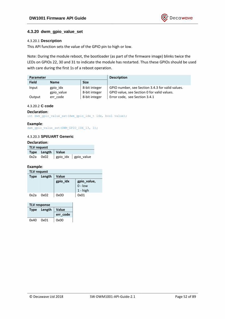
DW1001 Firmware API Guide
© Decawave Ltd 2018 SW-DWM1001-API-Guide-2.1 Page 52 of 89
4.3.20 dwm_gpio_value_set
4.3.20.1 Description
This API function sets the value of the GPIO pin to high or low.
Note: During the module reboot, the bootloader (as part of the firmware image) blinks twice the
LEDs on GPIOs 22, 30 and 31 to indicate the module has restarted. Thus these GPIOs should be used
with care during the first 1s of a reboot operation.
Parameter Description
Field Name Size
Input gpio_idx 8-bit integer GPIO number, see Section 3.4.3 for valid values. gpio_value 8-bit integer GPIO value, see Section 0 for valid values.
Output err_code 8-bit integer Error code, see Section 3.4.1
4.3.20.2 C code
Declaration: int dwm_gpio_value_set(dwm_gpio_idx_t idx, bool value);
Example: dwm_gpio_value_set(DWM_GPIO_IDX_13, 1);
4.3.20.3 SPI/UART Generic
Declaration: TLV request
Type Length Value 0x2a 0x02 gpio_idx gpio_value
Example:
TLV request
Type Length Value
gpio_idx gpio_value, 0 - low 1 - high
0x2a 0x02 0x0D 0x01
TLV response
Type Length Value
err_code
0x40 0x01 0x00

DW1001 Firmware API Guide
© Decawave Ltd 2018 SW-DWM1001-API-Guide-2.1 Page 53 of 89
4.3.21 dwm_gpio_value_get
4.3.21.1 Description
This API function reads the value of the GPIO pin.
Parameter Description
Field Name Size
Input gpio_idx 8-bit integer GPIO number, see Section 3.4.3 for valid values. Output gpio_value 8-bit integer GPIO value, see Section 0 for valid values.
4.3.21.2 C code
Declaration: int dwm_gpio_value_get(dwm_gpio_idx_t idx, bool* p_value);
Example: uint8_t value; dwm_gpio_value_get(DWM_GPIO_IDX_13, &value);
printf(“DWM_GPIO_IDX_13 value = %u\n”, value);
4.3.21.3 SPI/UART Generic
Declaration: TLV request
Type Length Value 0x2b 0x01 gpio_idx
Example:
TLV request
Type Length Value
gpio_idx
0x2b 0x01 0x0D
TLV response
Type Length Value Type Length Value err_code gpio_value
0x40 0x01 0x00 0x55 0x01 0x01
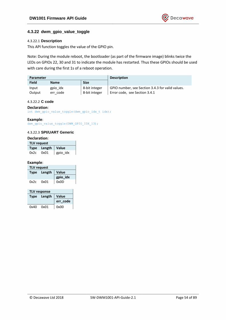
DW1001 Firmware API Guide
© Decawave Ltd 2018 SW-DWM1001-API-Guide-2.1 Page 54 of 89
4.3.22 dwm_gpio_value_toggle
4.3.22.1 Description
This API function toggles the value of the GPIO pin.
Note: During the module reboot, the bootloader (as part of the firmware image) blinks twice the
LEDs on GPIOs 22, 30 and 31 to indicate the module has restarted. Thus these GPIOs should be used
with care during the first 1s of a reboot operation.
Parameter Description
Field Name Size
Input gpio_idx 8-bit integer GPIO number, see Section 3.4.3 for valid values. Output err_code 8-bit integer Error code, see Section 3.4.1
4.3.22.2 C code
Declaration: int dwm_gpio_value_toggle(dwm_gpio_idx_t idx);
Example: dwm_gpio_value_toggle(DWM_GPIO_IDX_13);
4.3.22.3 SPI/UART Generic
Declaration: TLV request
Type Length Value 0x2c 0x01 gpio_idx
Example:
TLV request
Type Length Value
gpio_idx
0x2c 0x01 0x0D
TLV response
Type Length Value
err_code
0x40 0x01 0x00
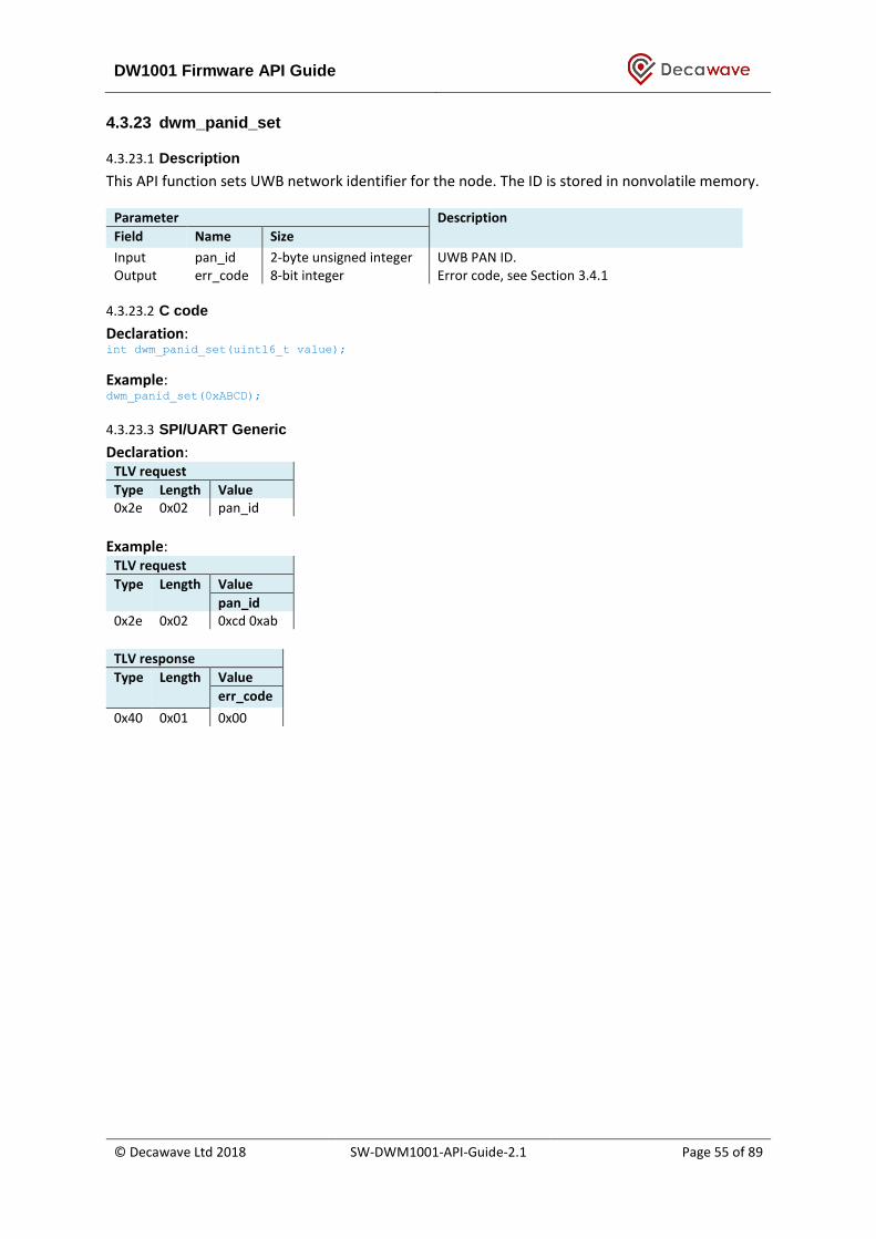
DW1001 Firmware API Guide
© Decawave Ltd 2018 SW-DWM1001-API-Guide-2.1 Page 55 of 89
4.3.23 dwm_panid_set
4.3.23.1 Description
This API function sets UWB network identifier for the node. The ID is stored in nonvolatile memory.
Parameter Description
Field Name Size
Input pan_id 2-byte unsigned integer UWB PAN ID. Output err_code 8-bit integer Error code, see Section 3.4.1
4.3.23.2 C code
Declaration: int dwm_panid_set(uint16_t value);
Example: dwm_panid_set(0xABCD);
4.3.23.3 SPI/UART Generic
Declaration: TLV request
Type Length Value 0x2e 0x02 pan_id
Example:
TLV request
Type Length Value
pan_id
0x2e 0x02 0xcd 0xab
TLV response
Type Length Value
err_code
0x40 0x01 0x00

DW1001 Firmware API Guide
© Decawave Ltd 2018 SW-DWM1001-API-Guide-2.1 Page 56 of 89
4.3.24 dwm_panid_get
4.3.24.1 Description
This API function get UWB network identifier from the node.
Parameter Description
Field Name Size
Input none Output err_code 8-bit integer Error code, see Section 3.4.1
pan_id 2-byte unsigned integer UWB PAN ID.
4.3.24.2 C code
Declaration: int dwm_panid_get(uint16_t* p_value);
Example: uint16_t panid;
if (DWM_OK == dwm_panid_get(&panid)) {
printf("panid=%u\n");
} else {
printf("FAILED\n");
}
4.3.24.3 SPI/UART Generic
Declaration: TLV request
Type Length 0x2f 0x00
Example:
TLV request
Type Length 0x2f 0x00
TLV response
Type Length Value Type Length Value err_code pan_id, 2 bytes (little
endian) 0x40 0x01 0x00 0x4d 0x02 0xcd 0xab

DW1001 Firmware API Guide
© Decawave Ltd 2018 SW-DWM1001-API-Guide-2.1 Page 57 of 89
4.3.25 dwm_node_id_get
4.3.25.1 Description
This API function get UWB network identifier from the node.
Parameter Description
Field Name Size
Input none Output err_code 8-bit integer Error code, see Section 3.4.1
node_id 8-byte, little endian UWB node address/ID.
4.3.25.2 C code
Declaration: int dwm_node_id_get(uint64_t *p_node_id)
Example: uint64_t node_id;
dwm_node_id_get(&node_id);
printf(“node id:0x%llx \n”, node_id);
4.3.25.3 SPI/UART Generic
Declaration: TLV request
Type Length 0x30 0x00
Example:
TLV request
Type Length 0x30 0x00
TLV response
Type Length Value Type Length Value err_code node_id, 8 bytes (little endian)
0x40 0x01 0x00 0x4e 0x08 0x99 0x0c 0x80 0x8d 0x63 0xef 0xca 0xde
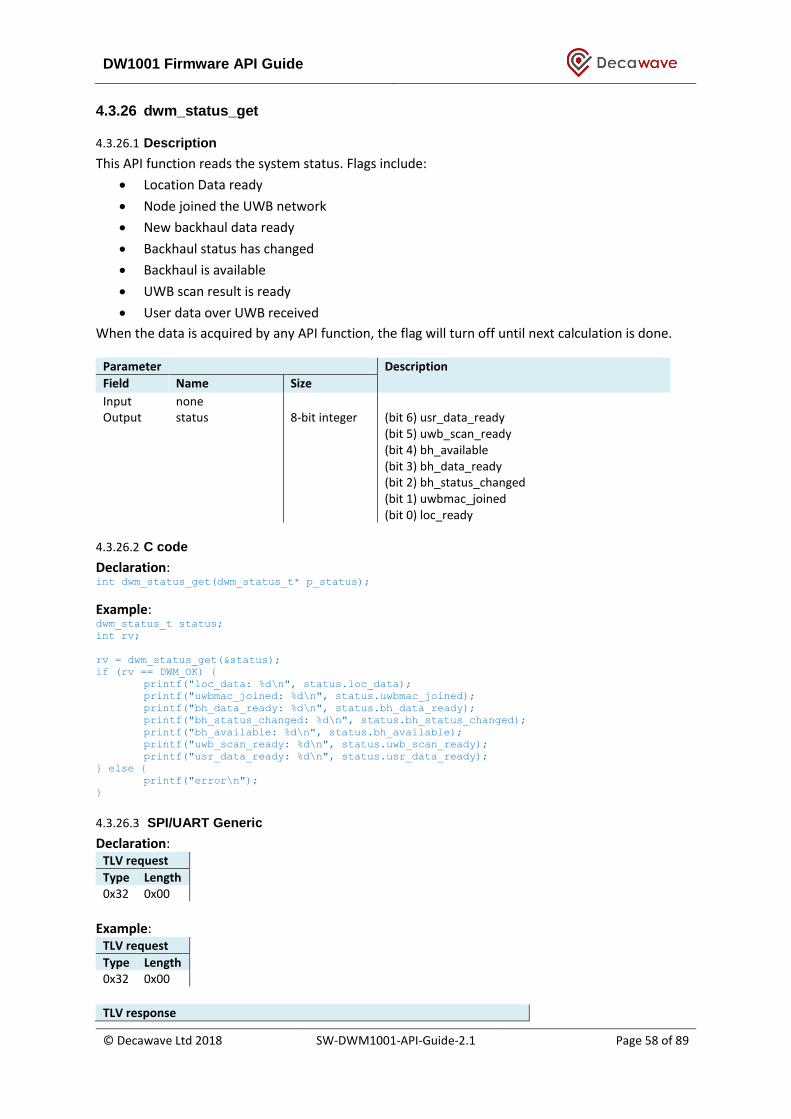
DW1001 Firmware API Guide
© Decawave Ltd 2018 SW-DWM1001-API-Guide-2.1 Page 58 of 89
4.3.26 dwm_status_get
4.3.26.1 Description
This API function reads the system status. Flags include:
• Location Data ready
• Node joined the UWB network
• New backhaul data ready
• Backhaul status has changed
• Backhaul is available
• UWB scan result is ready
• User data over UWB received
When the data is acquired by any API function, the flag will turn off until next calculation is done.
Parameter Description
Field Name Size
Input none Output status 8-bit integer (bit 6) usr_data_ready
(bit 5) uwb_scan_ready (bit 4) bh_available (bit 3) bh_data_ready (bit 2) bh_status_changed (bit 1) uwbmac_joined (bit 0) loc_ready
4.3.26.2 C code
Declaration: int dwm_status_get(dwm_status_t* p_status);
Example: dwm_status_t status;
int rv;
rv = dwm_status_get(&status);
if (rv == DWM_OK) {
printf("loc_data: %d\n", status.loc_data);
printf("uwbmac_joined: %d\n", status.uwbmac_joined);
printf("bh_data_ready: %d\n", status.bh_data_ready);
printf("bh_status_changed: %d\n", status.bh_status_changed);
printf("bh_available: %d\n", status.bh_available);
printf("uwb_scan_ready: %d\n", status.uwb_scan_ready);
printf("usr_data_ready: %d\n", status.usr_data_ready);
} else {
printf("error\n");
}
4.3.26.3 SPI/UART Generic
Declaration: TLV request
Type Length 0x32 0x00
Example:
TLV request
Type Length 0x32 0x00
TLV response
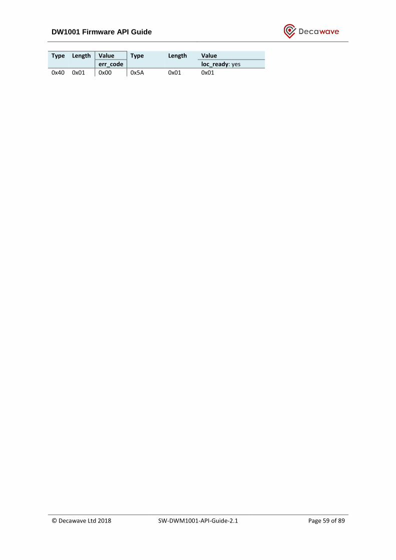
DW1001 Firmware API Guide
© Decawave Ltd 2018 SW-DWM1001-API-Guide-2.1 Page 59 of 89
Type Length Value Type Length Value err_code loc_ready: yes
0x40 0x01 0x00 0x5A 0x01 0x01
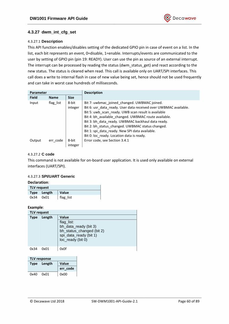
DW1001 Firmware API Guide
© Decawave Ltd 2018 SW-DWM1001-API-Guide-2.1 Page 60 of 89
4.3.27 dwm_int_cfg_set
4.3.27.1 Description
This API function enables/disables setting of the dedicated GPIO pin in case of event on a list. In the
list, each bit represents an event, 0=disable, 1=enable. Interrupts/events are communicated to the
user by setting of GPIO pin (pin 19: READY). User can use the pin as source of an external interrupt.
The interrupt can be processed by reading the status (dwm_status_get) and react according to the
new status. The status is cleared when read. This call is available only on UART/SPI interfaces. This
call does a write to internal flash in case of new value being set, hence should not be used frequently
and can take in worst case hundreds of milliseconds.
Parameter Description
Field Name Size
Input flag_list 8-bit integer
Bit 7: uwbmac_joined_changed. UWBMAC joined. Bit 6: usr_data_ready. User data received over UWBMAC available. Bit 5: uwb_scan_ready. UWB scan result is available Bit 4: bh_available_changed. UWBMAC route available. Bit 3: bh_data_ready. UWBMAC backhaul data ready. Bit 2: bh_status_changed. UWBMAC status changed. Bit 1: spi_data_ready. New SPI data available. Bit 0: loc_ready. Location data is ready.
Output err_code 8-bit integer
Error code, see Section 3.4.1
4.3.27.2 C code
This command is not available for on-board user application. It is used only available on external
interfaces (UART/SPI).
4.3.27.3 SPI/UART Generic
Declaration: TLV request
Type Length Value 0x34 0x01 flag_list
Example:
TLV request
Type Length Value
flag_list: bh_data_ready (bit 3) bh_status_changed (bit 2) spi_data_ready (bit 1) loc_ready (bit 0)
0x34 0x01 0x0f
TLV response
Type Length Value
err_code
0x40 0x01 0x00

DW1001 Firmware API Guide
© Decawave Ltd 2018 SW-DWM1001-API-Guide-2.1 Page 61 of 89
4.3.28 dwm_int_cfg_get
4.3.28.1 Description
This API function reads configuration flags that enables/disables the setting of dedicated GPIO pin
(CORE_INT) in case of events on the list internal to DWM module. This call is available only on
UART/SPI interfaces.
Parameter Description
Field Name Size
Input flag_list 8-bit integer
Bit 7: uwbmac_joined_changed. UWBMAC joined. Bit 6: usr_data_ready. User data received over UWBMAC available. Bit 5: uwb_scan_ready. UWB scan result is available Bit 4: bh_available_changed. UWBMAC route available. Bit 3: bh_data_ready. UWBMAC backhaul data ready. Bit 2: bh_status_changed. UWBMAC status changed. Bit 1: spi_data_ready. New SPI data available. Bit 0: loc_ready. Location data is ready.
Output err_code 8-bit integer
Error code, see Section 3.4.1
4.3.28.2 C code
Not available for user application.
4.3.28.3 SPI/UART Generic
Declaration: TLV request
Type Length 0x35 0x00
Example:
TLV request
Type Length 0x35 0x00
TLV response
Type Length Value Type Length Value err_code flag_list:
bh_data_ready (bit 3) bh_status_changed (bit 2) spi_data_ready (bit 1)
0x40 0x01 0x00 0x47 0x01 0x0e

DW1001 Firmware API Guide
© Decawave Ltd 2018 SW-DWM1001-API-Guide-2.1 Page 62 of 89
4.3.29 dwm_bh_status_get
4.3.29.1 Description
This API function get current UWBMAC backhaul status. The node must be configured as bridge.
There can be multiple pieces of origin information (origin_info) included in the response message.
The origin_cnt indicates the number of origins included.
Parameter Description
Field Name Size
Input none Output err_code 8-bit integer Error code, see Section 3.4.1
sf_number 16-bit integer, little endian Current superframe number bh_seat_map 32-bit integer, little endian Deat map in the current superframe origin_cnt 8-bit integer Number of origins, range is from 0 to 9 origin_info The origin info includes: {node_id, bh_seat,
hop_lvl} node_id 16-bit integer, little endian Origin address bh_seat 8-bit integer Deat that the origin occupies, range from 0 to 8 hop_lvl 8-bit integer Hop level
4.3.29.2 C code
Not available for user application.
4.3.29.3 SPI/UART Generic
Declaration: TLV request
Type Length 0x3a 0x00
Example:
TLV request
Type Length 0x3a 0x00
TLV response
Type Length Value Type Length Value err_code sf_number, bh_seat_map and node_id are
in little endian
0x40 0x01 0Cx00 0x5d 0x13
0x6c 0x00 0x07 0x00 0x00 0x00 0x03 0xf3
0x11 0x00 0x01 0xc3 0x11
0x01 0x01 0x66 0x11 0x02
0x01

DW1001 Firmware API Guide
© Decawave Ltd 2018 SW-DWM1001-API-Guide-2.1 Page 63 of 89
4.3.30 dwm_sec_key_set
4.3.30.1 Description
This API function sets security key used for encryption. The key is stored in nonvolatile memory. The
key that consists of just zeros is considered as invalid and is not set.
Parameter Description
Field Name Size
Input key 16 bytes The security key. Output err_code 8-bit integer Error code, see Section 3.4.1
4.3.30.2 C code
Declaration: int dwm_sec_key_set(dwm_sec_key_t* p_key);
Example: dwm_sec_key_t key;
key.byte[0] = 0x00;
key.byte[1] = 0x11;
key.byte[2] = 0x22;
...
key.byte[15] = 0xFF;
dwm_sec_key_set(&key);
4.3.30.3 SPI/UART Generic
Declaration: TLV request
Type Length Value 0x3c 0x10 16 bytes key
Example:
TLV request
Type Length Value
key
0x3c 0x10 0x00 0x11 0x22 0x33 0x44 0x55 0x66 0x77 0x88 0x99 0xAA 0xBB 0xCC 0xDD 0xEE 0xFF
TLV response
Type Length Value
err_code
0x40 0x01 0x00

DW1001 Firmware API Guide
© Decawave Ltd 2018 SW-DWM1001-API-Guide-2.1 Page 64 of 89
4.3.31 dwm_gpio_irq_cfg
4.3.31.1 Description
This API function registers GPIO pin interrupt call back functions.
Parameter Description
Field Name Size
Input gpio_idx 8-bit integer GPIO number, see Section 3.4.3 for valid values. Irq_type 8-bit integer interrupt type,
1 = rising, 2 = falling, 3 = both.
p_cb Function pointer Pointer to the callback function on the interrupt. p_data Data pointer Pointer to data passed to the callback function.
Output err_code 8-bit integer Error code, see Section 3.4.1
4.3.31.2 C code
Declaration: int dwm_gpio_irq_cfg(dwm_gpio_idx_t idx, dwm_gpio_irq_type_t irq_type, dwm_gpio_cb_t* p_cb,
void* p_data);
Example: void gpio_cb(void* p_data)
{
/* callback routine */
}
dwm_gpio_irq_cfg(DWM_GPIO_IDX_13, DWM_IRQ_TYPE_EDGE_RISING, &gpio_cb, NULL);
4.3.31.3 SPI/UART Generic
This command is not available on external interfaces (UART/SPI).
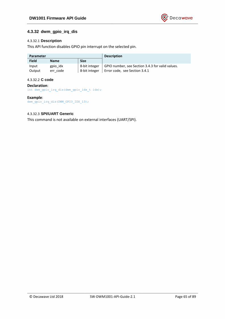
DW1001 Firmware API Guide
© Decawave Ltd 2018 SW-DWM1001-API-Guide-2.1 Page 65 of 89
4.3.32 dwm_gpio_irq_dis
4.3.32.1 Description
This API function disables GPIO pin interrupt on the selected pin.
Parameter Description
Field Name Size
Input gpio_idx 8-bit integer GPIO number, see Section 3.4.3 for valid values. Output err_code 8-bit integer Error code, see Section 3.4.1
4.3.32.2 C code
Declaration: int dwm_gpio_irq_dis(dwm_gpio_idx_t idx);
Example: dwm_gpio_irq_dis(DWM_GPIO_IDX_13);
4.3.32.3 SPI/UART Generic
This command is not available on external interfaces (UART/SPI).
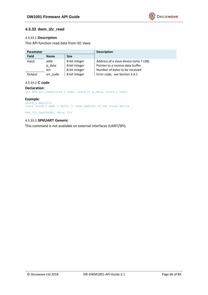
DW1001 Firmware API Guide
© Decawave Ltd 2018 SW-DWM1001-API-Guide-2.1 Page 66 of 89
4.3.33 dwm_i2c_read
4.3.33.1 Description
This API function read data from I2C slave.
Parameter Description
Field Name Size
Input addr 8-bit integer Address of a slave device (only 7 LSB) p_data 8-bit integer Pointer to a receive data buffer len 8-bit integer Number of bytes to be received
Output err_code 8-bit integer Error code, see Section 3.4.1
4.3.33.2 C code
Declaration: int dwm_i2c_read(uint8_t addr, uint8_t* p_data, uint8_t len);
Example: uint8_t data[2];
const uint8_t addr = 0x33; // some address of the slave device
dwm_i2c_read(addr, data, 2);
4.3.33.3 SPI/UART Generic
This command is not available on external interfaces (UART/SPI).

DW1001 Firmware API Guide
© Decawave Ltd 2018 SW-DWM1001-API-Guide-2.1 Page 67 of 89
4.3.34 dwm_i2c_write
4.3.34.1 Description
This API function writes data to I2C slave.
Parameter Description
Field Name Size
Input addr 8-bit integer Address of a slave device (only 7 LSB) p_data 8-bit integer Pointer to a receive data buffer len 8-bit integer Number of bytes to be received no_stop 8-bit integer 0 or 1. If set to 1, the stop condition is not generated
on the bus after the transfer has completed (allowing for a repeated start in the next transfer)
Output err_code 8-bit integer Error code, see Section 3.4.1
4.3.34.2 C code
Declaration: int dwm_i2c_write(uint8_t addr, uint8_t* p_data, uint8_t len, bool no_stop);
Example: uint8_t data[2];
const uint8_t addr = 1; // some address of the slave device
data[0] = 0xAA;
data[1] = 0xBB;
dwm_i2c_write(addr, data, 2, true);
4.3.34.3 SPI/UART Generic
This command is not available on external interfaces (UART/SPI).
DW1001 Firmware API Guide
© Decawave Ltd 2018 SW-DWM1001-API-Guide-2.1 Page 68 of 89
4.3.35 dwm_evt_cb_register
4.3.35.1 Description
This API function registers events listener. User application can wait for the events that are
registered to listen to by dwm_evt_wait(). The event can be triggered for example when LE finishes
position calculation and when distances are calculated. This call applies only for end user
application. Can not be used with SPI or UART. In low power mode in order to wake up from the
sleep, the event listener has to be registered, otherwise the user application will remain sleeping.
Events that the user can listen to:
• DWM_EVT_LOC_READY
• DWM_EVT_USR_DATA_READY
• DWM_EVT_BH_AVAILABLE
• DWM_EVT_UWBMAC_JOINED_CHANGED
• DWM_EVT_UWB_SCAN_READY
Input data is passed to the user in the callback function on_dwm_evt(). The user can get data for
actual event using event_id. See example below.
Parameter Description
Field Name Size
Input event_id_map 32-bit map flags of the events that user wants to/don’t want to listen to has to be set/cleared respectively, see
dwm_evt_wait() user_context_data data pointer data that the user wants inside the callback context
Output none
4.3.35.2 C code
Declaration: void dwm_evt_listener_register(uint32_t evt_id_map, void* p_context);
Example: dwm_evt_listener_register(DWM_EVT_USR_DATA_READY, NULL);
4.3.35.3 SPI/UART Generic
This command is not available on external interfaces (UART/SPI).
DW1001 Firmware API Guide
© Decawave Ltd 2018 SW-DWM1001-API-Guide-2.1 Page 69 of 89
4.3.36 dwm_evt_wait
4.3.36.1 Description
This API function is used to wait for event from DWM module. The listener to the event must be first
registered by dwm_evt_listener_register. If listener is registered and dwm_evt_wait is not used to
consume events the event buffer will overflow. When there are no events in the buffer, the
dwm_evt_wait will block.
Parameter Description
Field Name Size
Input none Output err_code 8-bit integer Error code, see Section 3.4.1
evt_list 8-bit integer Event list: loc_ready usr_data_ready uwb_scan_ready bh_available_changed uwbmac_joined_changed
4.3.36.2 C code
Declaration: int dwm_evt_wait(dwm_evt_t *p_evt);
Example: dwm_evt_listener_register(DWM_EVT_USR_DATA_READY, NULL);
void on_dwm_evt(dwm_evt_t *p_evt)
{
int i;
switch (p_evt->header.id) {
/* New location data */
case DWM_EVT_LOC_READY:
printf("\nT:%lu ", dwm_systime_us_get());
if (p_evt->loc.pos_available) {
printf("POS:[%ld,%ld,%ld,%u] ", p_evt->loc.pos.x,
p_evt->loc.pos.y, p_evt->loc.pos.z,
p_evt->loc.pos.qf);
} else {
printf("Location engine is disabled\n");
}
for (i = 0; i < p_evt->loc.anchors.dist.cnt; ++i) {
printf("DIST%d:", i);

DW1001 Firmware API Guide
© Decawave Ltd 2018 SW-DWM1001-API-Guide-2.1 Page 70 of 89
printf("0x%04X", (unsigned int)(p_evt->loc.anchors.dist.addr[i] &
0xffff));
if (i < p_evt->loc.anchors.an_pos.cnt) {
printf("[%ld,%ld,%ld]",
p_evt->loc.anchors.an_pos.pos[i].x,
p_evt->loc.anchors.an_pos.pos[i].y,
p_evt->loc.anchors.an_pos.pos[i].z);
}
printf("=[%lu,%u] ", p_evt->loc.anchors.dist.dist[i],
p_evt->loc.anchors.dist.qf[i]);
}
printf("\n");
break;
case DWM_EVT_USR_DATA_READY:
printf("hex:");
for (i = 0; i < p_evt->header.len; ++i) {
printf("%02x ", p_evt->usr_data[i]);
}
printf("\n");
break;
case DWM_EVT_UWB_SCAN_READY:
printf("[mode,rssi]: ");
for (i = 0; i < p_evt->uwb_scan.cnt; ++i) {
printf("[%u, %d]", p_evt->uwb_scan.mode[i], p_evt->uwb_scan.rssi[i]);
}
printf("\n");
break;
case DWM_EVT_BH_AVAILABLE_CHANGED:
printf("backhaul available = %d\n", p_evt->bh_available);
break;
DW1001 Firmware API Guide
© Decawave Ltd 2018 SW-DWM1001-API-Guide-2.1 Page 71 of 89
case DWM_EVT_UWBMAC_JOINED_CHANGED:
printf("UWBMAC joined = %d\n", p_evt->uwbmac_joined);
break;
default:
break;
}
/* Indicate the application has finished the tasks and can now */
dwm_sleep();
}
…
int rv;
dwm_evt_t evt;
rv = dwm_evt_wait(&evt);
if (rv == DWM_ERR_OVERRUN) {
printf("event buffer overflow\n");
} else {
on_dwm_evt(&evt);
}
4.3.36.3 SPI/UART Generic
This command is not available on external interfaces (UART/SPI).
DW1001 Firmware API Guide
© Decawave Ltd 2018 SW-DWM1001-API-Guide-2.1 Page 72 of 89
5 UART SHELL COMMANDS
Shell mode shares UART interface with Generic mode. DWM1001 starts by default in UART Generic
mode after reset. The Shell mode can be switched to by pressing ENTER twice within 1 second. The
Generic mode can be switched to by executing command “quit” when in Shell mode. Shell mode and
Generic mode can be switched back and forth.
Enter the Shell command and press “Enter” to execute the command. Press “Enter” without any
command in Shell mode to repeat the last command. The following sub-sections provides overview
of the Shell commands.
5.1 Command group: Base
The following commands are discussed in this section:
• ?: this help
• help: this help
• quit: quit
5.1.1 ? (question mark)
Displays help.
Example: dwm> ? Usage: <command> [arg0] [arg1] Build-in commands: ** Command group: Base ** ?: this help help: this help quit: quit
5.1.2 help
Displays help, same as command “?”, see section 5.1.1.
5.1.3 quit
Quit shell and switch UART into API mode.
Example: dwm> quit /* press enter twice to switch to shell mode again*/
DW1001 Firmware API Guide
© Decawave Ltd 2018 SW-DWM1001-API-Guide-2.1 Page 73 of 89
5.2 command group: GPIO
The following commands are discussed in this section:
• gc: GPIO clear
• gg: GPIO get
• gs: GPIO set
• gt: GPIO toggle
5.2.1 gc: GPIO clear
Clears GPIO pin. See section 3.4.3 for valid GPIO number.
Example: dwm> gc Usage: gc <pin> dwm> gc 13 gpio13: 0
5.2.2 gg: GPIO get
Reads GPIO pin level. See section 3.4.3 for valid GPIO number.
Example: dwm> gg Usage: gg <pin> dwm> gg 13 gpio13: 0
5.2.3 gs: GPIO set
Sets GPIO as output and sets its value. See section 3.4.3 for valid GPIO number.
Example: dwm> gs Usage: gs <pin> dwm> gs 13 gpio13: 1
5.2.4 gt: GPIO toggle
Toggles GPIO pin (must be output). See section 3.4.3 for valid GPIO number.
Example: dwm> gt Usage: gt <pin> dwm> gt 13

DW1001 Firmware API Guide
© Decawave Ltd 2018 SW-DWM1001-API-Guide-2.1 Page 74 of 89
gpio13: 0
5.3 Command group: SYS
The following commands are discussed in this section:
• f: Show free memory on the heap
• ps: Show running threads
• pms: Show PM tasks
• reset: Reboot the system
• si: System info
• ut: Show device uptime
• frst: Factory reset
5.3.1 f: Show free memory on the heap
Show free memory on the heap.
Example: dwm> f [000014.560 INF] mem: free=3888 alloc=9184 tot=13072
5.3.2 ps: Show running threads
Show info about running threads.
Example: dwm> ps
ID NAME PRIO STACK USED
1 idle 31 512 304
2 ser 13 768 360
3 svc 15 1024 512
4 uwb 5 2560 760
5 api 10 2048 1180
6 sd 6 1024 352
7 ble 7 1024 392
8 le 14 2048 688
9 pm 17 512 304
10 sh 16 2048 1096
5.3.3 pms: Show PM tasks
Show power managements tasks. IDL means that task is idle. USE means that task is allocated in the power management.
Example: dwm> pms

DW1001 Firmware API Guide
© Decawave Ltd 2018 SW-DWM1001-API-Guide-2.1 Page 75 of 89
ID NAME USE IDL ALM
0 ble 1 0 0
1 le 1 1 0
2 sh 1 0 0
3 -- 0 0 0
4 -- 0 0 0
5.3.4 reset: Reboot the system
Reboot the system.
Example: dwm> reset /* node resets and boots in binary mode */
5.3.5 si: System info
System info
Example: dwm> si
[000209.670 INF] cfg:
[000209.670 INF] >fw2=x00044000
[000209.670 INF] board=DWM1001_A2
[000209.670 INF] cfg_ver=x00010700
[000209.680 INF] fw_ver=x01020001
[000209.680 INF] hw_ver=xDECA002A
[000209.690 INF] opt=x11C1A340
[000209.690 INF] fw_size[0]=x0001F000
[000209.690 INF] fw_size[1]=x00022000
[000209.700 INF] fw_size[2]=x0003C000
[000209.700 INF] fw_csum[0]=x9445F89E
[000209.700 INF] fw_csum[1]=x36D9BFF1
[000209.710 INF] fw_csum[2]=x1A3EDB96
[000209.710 INF] opt: ACC LEDS PASV TWR LE BPC UWB0 I2C SPI UART
[000209.720 INF] mcu: temp=28.8 hfclk=xtal:on lfclk=xtal:on
[000209.720 INF] uptime: 00:03:29.720 0 days (209720 ms)
[000209.730 INF] mem: free=2720 alloc=10068 tot=12788
[000209.730 INF] uwb: ch5 prf64 plen128 pac8 txcode9 rxcode9 sfd0 baud6800 phrext sfdto129
smart1
[000209.740 INF] uwb: tx_pwr=xC3/x24446484 125:250:500:norm[ms]=17:14:11:8[dB] pgcnt=804
temp=30
[000209.750 INF] uwb0: lna=0 xtaltrim=15 tx_delay=16442 rx_delay=16442
[000209.760 INF] uwb0: ID dev=xDECA0130 part=xC2230C93 lot=x010B1044
DW1001 Firmware API Guide
© Decawave Ltd 2018 SW-DWM1001-API-Guide-2.1 Page 76 of 89
[000209.760 INF] uwb0: panid=x0000 addr=xDECA36BE40B30C93
[000209.770 INF] mode: tn (pasv,twr,np,le)
[000209.780 INF] uwbmac: disconnected
[000209.850 INF] cfg: sync=0 fwup=0 ble=0 leds=1 le=1 lp=0 stat_det=1 mode=0 upd_rate_norm=1
upd_rate_stat=100 label=DW0C93
[000209.870 INF] sec: off
5.3.6 ut: Show device uptime
Show device uptime. Example: dwm> ut [000003.680 INF] uptime: 00:07:49.210 0 days (469210 ms)
5.3.7 frst: Factory reset
Factory reset.
Example: dwm> frst
5.4 Command group: SENS
The following commands are discussed in this section:
twi: General purpose TWI read aid: Read ACC device ID av: Read ACC values
5.4.1 twi: General purpose TWI read
General purpose I2C/TWI read.
Example: use twi to read accelerometer id. This should return the same value as using “aid” command. dwm> twi
Usage: twi <addr> <reg> [bytes to read (1 or 2)]
dwm> twi 0x33 0x0f 1
twi: addr=0x33, reg[0x0f]=0x33
5.4.2 aid: Read ACC device ID
Read ACC device ID Example: dwm> aid acc: 0x33
DW1001 Firmware API Guide
© Decawave Ltd 2018 SW-DWM1001-API-Guide-2.1 Page 77 of 89
5.4.3 Av: Read ACC values.
Example: dwm> av acc: x = 240, y = -3792, z = 16240 dwm> av acc: x = 32, y = -3504, z = 15872 dwm> av acc: x = 160, y = -3600, z = 16144
5.5 Command group: CRYPTO
5.5.1 cks: set 128-bit encryption key
Example:
dwm> cks
Usage: cks <word0> <word1> <word2> <word3>
dwm> cks 0x123456 0x234567 0x345678 0xabcdef
key_set: 00123456 00234567 00345678 00ABCDEF
5.6 Command group: LE
The following commands are discussed in this section:
• les: Show meas. and pos.
• lec: Show meas. and pos. in CSV
• lep: Show pos. in CSV
5.6.1 les: Show meas. and pos.
Show distances to ranging anchors and the position if location engine is enabled. Sending this
command multiple times will turn on/off this functionality. With variable 1 following this command,
the timestamp will also show along with the distances/position.
Example 1: dwm> les
1151[5.00,8.00,2.25]=6.48 0CA8[0.00,8.00,2.25]=6.51 111C[5.00,0.00,2.25]=3.18
1150[0.00,0.00,2.25]=3.16 le_us=2576 est[2.57,1.98,1.68,100]
Example 2: dwm> les 1
dwm> ts=4465273 diff=4465273 007E[2.62,5.91,5.97]=5.33
ts=4565273 diff=100000 007E[2.62,5.91,5.97]=5.37
DW1001 Firmware API Guide
© Decawave Ltd 2018 SW-DWM1001-API-Guide-2.1 Page 78 of 89
5.6.2 lec: Show meas. and pos. in CSV
Show distances to ranging anchors and the position if location engine is enabled in CSV format.
Sending this command multiple times will turn on/off this functionality.
Example: dwm> lec
DIST,4,AN0,1151,5.00,8.00,2.25,6.44,AN1,0CA8,0.00,8.00,2.25,6.50,AN2,111C,5.00,0.00,2.25,3.24,A
N3,1150,0.00,0.00,2.25,3.19,POS,2.55,2.01,1.71,98
5.6.3 lep: Show pos. in CSV
Show position in CSV format. Sending this command multiple times will turn on/off this functionality.
Example: dwm> lep
POS,2.57,2.00,1.67,97
5.7 Command group: UWBMAC
The following commands are described in this section:
• nmg: Get node mode
• nmp: Set mode to PN (passive)
• nmo: Set mode to PN (off)
• nma: Set mode to AN
• nmi: Set mode to AIN
• nmt: Set mode to TN
• nmtl: Set mode to TN-LP
• nmb: Set mode to BN
• bpc: Toggle BW/TxPWR comp
• la: Show AN list
• ln: List BH nodes
• lr: List routes
• lrn: List next routes
• nis: Set Network ID
• nls: Set node label
• stg: Get stats
• stc: Clear stats
• udi: Show received IoT data
• uui: Send IoT data
5.7.1 nmg: Get node mode
Get node mode info.
Example: dwm> nmg
DW1001 Firmware API Guide
© Decawave Ltd 2018 SW-DWM1001-API-Guide-2.1 Page 79 of 89
mode: tn (act,twr,np,nole)
5.7.2 nmp: Set mode to PN (passive)
Enable active offline option and resets the node.
Example: dwm> nmp
5.7.3 nmo: Set mode to PN (off)
Enable passive offline option and resets the node.
Example: dwm> nmo
/* press enter twice to switch to shell mode after reset*/
DWM1001 TWR Real Time Location System
5.7.4 nma: Set mode to AN
Configures node to as anchor, active and reset the node.
Example: dwm> nma
/* press Enter twice to switch to shell mode after reset */
5.7.5 nmi: Set mode to AIN
Configures node to as anchor - initiator, active and reset the node.
Example: dwm> nmi
/* press enter twice to switch to shell mode after reset */
5.7.6 nmt: Set mode to TN
Configures node to as tag, active, low power and resets the node.
Example: dwm> nmtl
/* press enter twice to switch to shell mode after reset */
5.7.7 nmtl: Set mode to TN-LP
Configures node to as tag, active, low power and resets the node.
Example: dwm> nmtl
DW1001 Firmware API Guide
© Decawave Ltd 2018 SW-DWM1001-API-Guide-2.1 Page 80 of 89
/* press enter 3 times to switch to wake up the device from lower power mode and enter shell
mode after reset */
5.7.8 nmb: Set mode to BN
Configures node to as bridge node and resets the node.
Example: dwm> nmb
/* press enter twice to switch to shell mode after reset */
5.7.9 bpc: Toggle BW/TxPWR comp
Toggle UWB bandwidth / tx power compensation.
Example: dwm> bpc
BW/TxPwr comp off
dwm> bpc
BW/TxPwr comp on
5.7.10 la: Show AN list
Show anchor list.
Example: dwm> la
[003452.590 INF] AN: cnt=4 seq=x03
[003452.590 INF] 0) id=DECA5419E2E01151 seat=0 idl=0 seens=0 col=0 cl=000F nbr=000F fl=4002
opt=03C1B046 hw=DE41010
0 fw=01010101 fwc=7B033F01
[003452.600 INF] 1) id=DECA78A55EB00CA8 seat=1 idl=1 seens=119 col=0 cl=000F nbr=0000
fl=0000 opt=03C1B042 hw=DE410
100 fw=01010101 fwc=7B033F01
[003452.620 INF] 2) id=DECAFCED8D50111C seat=2 idl=1 seens=103 col=0 cl=000F nbr=0000
fl=0000 opt=03C1B042 hw=DE410
100 fw=01010101 fwc=7B033F01
[003452.640 INF] 3) id=DECA51421A901150 seat=3 idl=0 seens=81 col=0 cl=000F nbr=0000 fl=0000
opt=03C1B042 hw=DE4101
00 fw=01010101 fwc=7B033F01
5.7.11 ln: list BH nodes
List nodes heard by BN through backhaul, only works for BN.
Example: dwm> ln
[020716.280 INF] BH: cnt=3
[020716.280 INF] * 0) id=0C99 fl=0007 bh_map=0000 peer_cnt=2 child_cnt=14 hop_lvl=0 idles=0
DW1001 Firmware API Guide
© Decawave Ltd 2018 SW-DWM1001-API-Guide-2.1 Page 81 of 89
[020716.290 INF] childs:
[020716.290 INF] peers:
[020716.290 INF] 0) PAR id=1166 fl=0003 peer_cnt=2 hop_lvl=1 rssi=-94
[020716.300 INF] 1) PAR id=11F3 fl=0007 peer_cnt=2 hop_lvl=1 rssi=-80
[020716.310 INF] * 1) id=11F3 fl=0007 bh_map=0000 peer_cnt=2 child_cnt=0 hop_lvl=1 idles=0
[020716.320 INF] childs:
[020716.320 INF] peers:
[020716.320 INF] 0) PAR id=1166 fl=0003 peer_cnt=2 hop_lvl=1 rssi=-90
[020716.330 INF] 1) PAR id=0C99 fl=0007 peer_cnt=2 hop_lvl=0 rssi=-80
[020716.340 INF] * 2) id=1166 fl=0003 bh_map=0000 peer_cnt=2 child_cnt=0 hop_lvl=1 idles=0
[020716.350 INF] childs:
[020716.350 INF] peers:
[020716.350 INF] 0) PAR id=0C99 fl=0007 peer_cnt=2 hop_lvl=0 rssi=-94
[020716.360 INF] 1) PAR id=11F3 fl=0007 peer_cnt=2 hop_lvl=1 rssi=-90
[020716.370 INF]
5.7.12 lr: list routes
Example: dwm> lr
[020763.450 INF] bh : cnt=9 sf=238 seq=xE4 bn | ul_loc ul_iot | dl_iot
[020763.450 INF] 0) x11F3 : x11F3 -> x0C99 : x0C99 | 0 3217 | 1
[020763.460 INF] 1) x1166 : x1166 -> x0C99 : x0C99 | 0 127 | 0
[020763.470 INF] 2) - :
[020763.470 INF] 3) - :
[020763.470 INF] 4) - :
[020763.480 INF] 5) - :
[020763.480 INF] 6) - :
[020763.480 INF] 7) - :
[020763.490 INF] 8) - :
[020763.490 INF]
5.7.13 lr: list next routes
Example: dwm> lr
[020787.380 INF] bhn: cnt=9 sf=476 seq=xE5 bn | ul_loc ul_iot | dl_iot
[020787.380 INF] 0) x11F3 : x11F3 -> x0C99 : x0C99 | 0 0 | 0
[020787.390 INF] 1) x1166 : x1166 -> x0C99 : x0C99 | 0 0 | 0
[020787.400 INF] 2) - :
[020787.400 INF] 3) - :
[020787.410 INF] 4) - :
[020787.410 INF] 5) - :
[020787.410 INF] 6) - :
[020787.410 INF] 7) - :
[020787.420 INF] 8) - :

DW1001 Firmware API Guide
© Decawave Ltd 2018 SW-DWM1001-API-Guide-2.1 Page 82 of 89
[020787.420 INF]
5.7.14 nis: set Network PAN ID
Example: dwm> nis
usage: nis <panid>
dwm> nis 0x1234
nis: ok
5.7.15 nls: Set node label
Example: dwm> nls
usage: nls <label>
dwm> nls DW0C93
nis: ok
5.7.16 stg: Get stats
Displays statistics.
Example: dwm> stg
uptime: 0
memfree: 0
mcu_temp: 0
rtc_drift: 0.000000
ble_con_ok: 0
ble_dis_ok: 0
ble_err: 0
uwb0_intr: 0
uwb0_rst: 0
rx_ok: 56454
rx_err: 0
tx_err: 0
tx_errx: 0
bcn_tx_ok: 1661
bcn_tx_err: 0
bcn_rx_ok: 0
alma_tx_ok: 51
alma_tx_err: 0
alma_rx_ok: 0
cl_tx_ok: 0
cl_tx_err: 0
cl_rx_ok: 0
cl_coll: 0
DW1001 Firmware API Guide
© Decawave Ltd 2018 SW-DWM1001-API-Guide-2.1 Page 83 of 89
fwup_tx_ok: 0
fwup_tx_err: 0
fwup_rx_ok: 0
svc_tx_ok: 0
svc_tx_err: 0
svc_rx_ok: 0
clk_sync: 0
twr_ok: 0
twr_err: 0
res[0]: 0
res[1]: 0
res[2]: 0
res[3]: 0
res[4]: 0
res[5]: 0
res[6]: 0
res[7]: 0
tot_err: 0
5.7.17 stc: Clear stats
Clears statistics.
Example: dwm> stc
5.7.18 udi: Show received IoT data
Example: dwm> udi
dl: len=4: 34 56 78 90
5.7.19 uui: Send IoT data
Example: dwm> uui
usage: uui <hex_string> [cnt]
dwm> uui 1234abcd 4
ul: len=4 cnt=4 rv=4: 12 34 AB CD
5.8 Command group: API
The following commands are discussed in this section:
• tlv: Send TLV frame
• aurs: Set upd rate
• aurg: Get upd rate
• apg: Get pos

DW1001 Firmware API Guide
© Decawave Ltd 2018 SW-DWM1001-API-Guide-2.1 Page 84 of 89
• aps: Set pos
• acas: Set anchor configuration
• acts: Set tag configuration
5.8.1 tlv: Send TLV frame
Parses given TLV frame. See Section 4 for valid TLV commands.
Example: read node configuration dwm> tlv 8 0
OUTPUT FRAME:
40 01 00 46 02 b0 00
Example: toggles GPIO pin 13 dwm> tlv 44 1 13
OUTPUT FRAME:
40 01 00
5.8.2 aurs: Set upd rate
Usage aurs <ur> <urs> Where <ur> is update rate (x100ms) <urs> is update rate stationary (x100ms) The following example sets the update rate to 100ms (10Hz) and update rate for stationary mode 1s (1hz) Example : dwm> aurs 1 10
5.8.3 aurg: Get upd rate
Get position update rate. See section 4.3.4 for more detail.
Example: dwm> aurg
err code: 0, upd rate: 10, 20(stat)
5.8.4 apg: Get pos
Get position of the node. See section 3.4.2 for more detail.
Example: dwm> apg
x:100 y:120 z:2500 qf:100
5.8.5 aps : Set pos
Set position of the node. See section 3.4.2 for more detail. Example: dwm> aps

DW1001 Firmware API Guide
© Decawave Ltd 2018 SW-DWM1001-API-Guide-2.1 Page 85 of 89
Usage aps <x> <y> <z> dwm> aps 100 120 2500 err code: 0 Set position of the node. See section 3.4.2 for more detail.
5.8.6 acas: Set anchor config
Configures node as anchor with given options. See section 4.3.6 for more detail. Note that this command only sets the configuration parameters. To make effect of the settings, users should issue s reset command, see section 5.3.4 for more detail. Example: dwm> acts Usage acts <meas_mode> <accel_en> <low_pwr> <loc_en> <leds> <ble> <uwb> <fw_upd> <sec> dwm> acts 0 1 0 1 1 0 0 0 0 err code: 0
5.8.7 acts: Set tag config
Configures node as tag with given options. See section 4.3.5 for more detail. Note that this command only sets the configuration parameters. To make effect of the settings, users should issue s reset command, see section 5.3.4 for more detail. Example: dwm> acts Usage acts <meas_mode> <accel_en> <low_pwr> <loc_en> <leds> <ble> <uwb> <fw_upd> <sec> dwm> acts 0 1 0 1 1 0 0 0 0 err code: 0
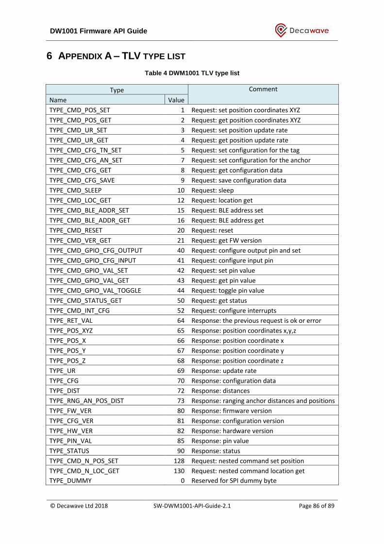
DW1001 Firmware API Guide
© Decawave Ltd 2018 SW-DWM1001-API-Guide-2.1 Page 86 of 89
6 APPENDIX A – TLV TYPE LIST
Table 4 DWM1001 TLV type list
Type Comment
Name Value
TYPE_CMD_POS_SET 1 Request: set position coordinates XYZ
TYPE_CMD_POS_GET 2 Request: get position coordinates XYZ
TYPE_CMD_UR_SET 3 Request: set position update rate
TYPE_CMD_UR_GET 4 Request: get position update rate
TYPE_CMD_CFG_TN_SET 5 Request: set configuration for the tag
TYPE_CMD_CFG_AN_SET 7 Request: set configuration for the anchor
TYPE_CMD_CFG_GET 8 Request: get configuration data
TYPE_CMD_CFG_SAVE 9 Request: save configuration data
TYPE_CMD_SLEEP 10 Request: sleep
TYPE_CMD_LOC_GET 12 Request: location get
TYPE_CMD_BLE_ADDR_SET 15 Request: BLE address set
TYPE_CMD_BLE_ADDR_GET 16 Request: BLE address get
TYPE_CMD_RESET 20 Request: reset
TYPE_CMD_VER_GET 21 Request: get FW version
TYPE_CMD_GPIO_CFG_OUTPUT 40 Request: configure output pin and set
TYPE_CMD_GPIO_CFG_INPUT 41 Request: configure input pin
TYPE_CMD_GPIO_VAL_SET 42 Request: set pin value
TYPE_CMD_GPIO_VAL_GET 43 Request: get pin value
TYPE_CMD_GPIO_VAL_TOGGLE 44 Request: toggle pin value
TYPE_CMD_STATUS_GET 50 Request: get status
TYPE_CMD_INT_CFG 52 Request: configure interrupts
TYPE_RET_VAL 64 Response: the previous request is ok or error
TYPE_POS_XYZ 65 Response: position coordinates x,y,z
TYPE_POS_X 66 Response: position coordinate x
TYPE_POS_Y 67 Response: position coordinate y
TYPE_POS_Z 68 Response: position coordinate z
TYPE_UR 69 Response: update rate
TYPE_CFG 70 Response: configuration data
TYPE_DIST 72 Response: distances
TYPE_RNG_AN_POS_DIST 73 Response: ranging anchor distances and positions
TYPE_FW_VER 80 Response: firmware version
TYPE_CFG_VER 81 Response: configuration version
TYPE_HW_VER 82 Response: hardware version
TYPE_PIN_VAL 85 Response: pin value
TYPE_STATUS 90 Response: status
TYPE_CMD_N_POS_SET 128 Request: nested command set position
TYPE_CMD_N_LOC_GET 130 Request: nested command location get
TYPE_DUMMY 0 Reserved for SPI dummy byte

DW1001 Firmware API Guide
© Decawave Ltd 2018 SW-DWM1001-API-Guide-2.1 Page 87 of 89
7 APPENDIX B – BIBLIOGRAPHY
1. nRF5 Getting Started, available from www.nordicsemi.com
2. IEEE 802.15.4‐2011 or “IEEE Std 802.15.4™‐2011” (Revision of IEEE Std 802.15.4-2006). IEEE
Standard for Local and metropolitan area networks— Part 15.4: Low-Rate Wireless Personal
Area Networks (LR-WPANs). IEEE Computer Society Sponsored by the LAN/MAN Standards
Committee. Available from http://standards.ieee.org/
3. DWM1001 Firmware User Guide, available from www.decawave.com
4. DWM1001 System Overview, available from www.decawave.com
5. DWM1001 on-board package, available from www.decawave.com
6. DWM1001 Host API package, available from www.decawave.com
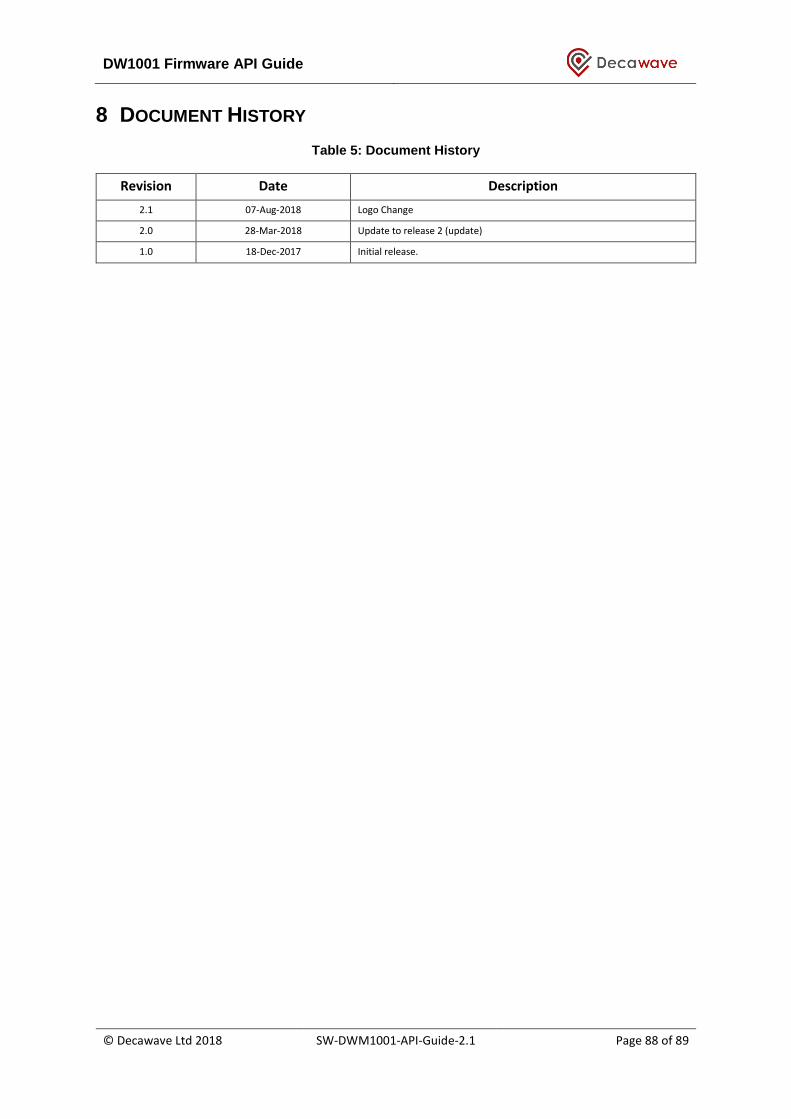
DW1001 Firmware API Guide
© Decawave Ltd 2018 SW-DWM1001-API-Guide-2.1 Page 88 of 89
8 DOCUMENT HISTORY
Table 5: Document History
Revision Date Description
2.1 07-Aug-2018 Logo Change
2.0 28-Mar-2018 Update to release 2 (update)
1.0 18-Dec-2017 Initial release.

DW1001 Firmware API Guide
© Decawave Ltd 2018 SW-DWM1001-API-Guide-2.1 Page 89 of 89
9 FURTHER INFORMATION
Decawave develops semiconductors solutions, software, modules, reference designs - that enable
real-time, ultra-accurate, ultra-reliable local area micro-location services. Decawave’s technology
enables an entirely new class of easy to implement, highly secure, intelligent location functionality
and services for IoT and smart consumer products and applications.
For further information on this or any other Decawave product, please refer to our website
www.decawave.com.