dw017 mitre saw - 2helpu dossier/d… · karl evans product details ... dw017 mitre saw type 1 ......
TRANSCRIPT
January 2003S. Hurt
IntroductionBill Of Material
DW017-----A
ExplodedDrawing
E13442E13443
RepairInstructions
R11368
NewParts
22
WiringDiagram
MainMenu
DW017Mitre Saw
TYPE 1Special
Instructions

F:\DOSSIERS\dw017\dw017pre.DOCLast printed 27/02/03 16:28
DW017 – Mitre Saw
MANUFACTURING PLANTTatry
LAUNCH DATE01/01/03
BULK DATE
PRODUCT ENGINEERSteve Hurt
Program Manager/EngineerKarl Evans
PRODUCT DETAILS
DW017K2H 24.0 Volt Heavy Duty Compound Slide Mitre Saw
Ø Double insulated DEWALT 65mm fan cooled motor with replaceable brushes for maximum power in hardwood
Ø New mitre angle adjustment system provides accurate and consistent setting of mitre angles between 0 and60° right and 0 and 50° left
Ø The innovative grooving stop allows adjustment of the cutting depth for grooving and rebating applicationsØ The large dual sliding fence mechanism gives maximum support in large material cuts at any angle or
combination of anglesØ Horizontal rails create additional capacity for larger materialsØ The aluminum base construction provides stability to the saw while still retaining its portabilityØ 60° right angle provides enough capacity for the most difficult applicationsØ Mitre and bevel angle detents for quick and easy set up of the saw. Battery 3.0 NiMH
Technical Information
Type No. 1 CURRENT STATUS & MAJOR CHANGES .
LAUNCH MARKETS & QUANTITIES
VoltagePower OutputBlade SpeedBlade DiameterBlade BoreBevel Capacity
Mitre Capacity [right/left]Max. Depth of Cut at 90°Max. Depth of Cut at 45ºCutting Capacity at 90°/90°Cutting Capacity at 45°/90°Cutting Capacity at 90°/45°
24 Volts630 Watts4000 rpm216 mm30 mm-2°-48° left
60°/5070 mm50 mm(W x H) 300x70 mm(W x H) 212x70 mm(W x H) 300x50 mm

TYP.
WWW.2helpU.com 22 - 10 - 02E13442
DW017 1
56
51
44
55
44
35
140
43
5453
144
29
30
57
145
58
366
4141 34
111
110109
110
5049
48
6
31
21
2511 24
26
2830
29
10
22
26
23
42
2nd1st
4th
333rd
466
32
137
138
800
8
965
2019
15 18
17
6
16
147
13
9
1
2
27
1213
4
3
3938
37
14640
45
46
47
6
TYP.
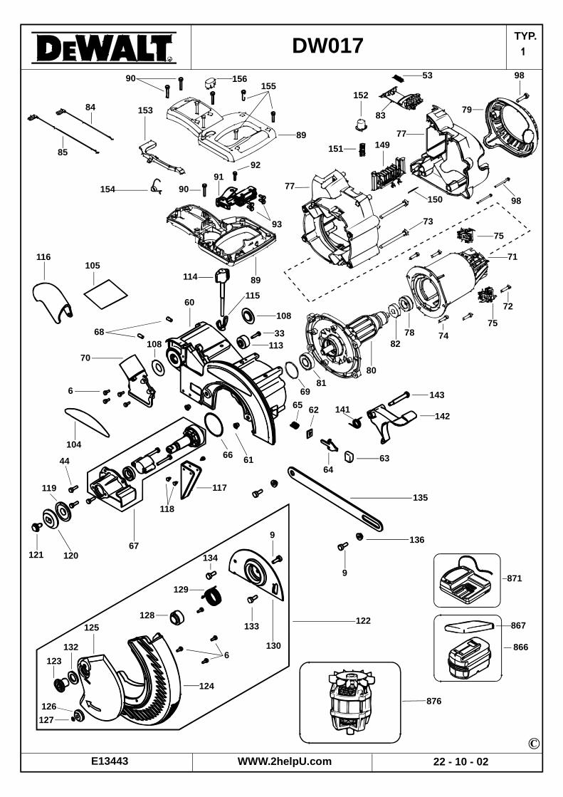
WWW.2helpU.com 22 - 10 - 02E13443
DW017 1
33
143
14214165 62
60
68
70
6
104
108
66 61
12167
117
118
120
119
44 6364
135
136
9
122
9
134
130
133
129
128
6
124
125
132
123
126127
90 156155
89
92
93
9190
153
154
84
85
116105
108
114
115
71
7578
82
72
8081
69
89
53 98
7983
152
151
77149
98150
73
77
74
75
876
871
867
866
113
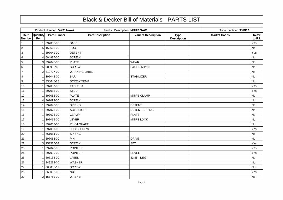
Black & Decker Bill of Materials - PARTS LIST
Page 1
Product Number DW017-----A Product Description MITRE SAW Type Identifier TYPE 1
ItemNumber
QuantityPer
Part Number Part Description Variant Description TypeDescription
Market Codes Referto R.I.
1 1 397038-00 BASE Yes
2 5 153612-00 FOOT No
3 1 397041-00 DETENT Yes
4 4 604987-00 SCREW No
5 3 397045-00 PLATE WEAR No
6 25 98093-76 SCREW Pan HD M4*10 No
7 2 610707-00 WARNING LABEL No
8 1 397042-00 BAR STABILIZER No
9 7 330045-23 SCREW.TEMP No
10 1 397087-00 TABLE SA Yes
11 1 397085-00 STUD Yes
12 1 397062-00 PLATE MITRE CLAMP No
13 4 861092-00 SCREW No
14 1 397070-00 SPRING DETENT No
15 1 397073-00 ACTUATOR DETENT SPRING No
16 1 397075-00 CLAMP PLATE No
17 1 397065-00 LEVER MITRE LOCK No
18 1 397068-00 PIVOT SHAFT No
19 1 397061-00 LOCK SCREW Yes
20 1 761054-00 SPRING No
21 1 397063-00 PIN DRIVE No
22 3 153576-03 SCREW SET Yes
23 1 397048-00 POINTER Yes
24 1 397090-00 POINTER BEVEL Yes
25 1 605153-00 LABEL 33.85 - DEG No
26 2 249233-00 WASHER No
27 1 860085-19 SCREW No
28 1 860092-05 NUT Yes
29 2 153781-00 WASHER No

Black & Decker Bill of Materials - PARTS LIST
Page 2
28 1 860092-05 NUT Yes
29 2 153781-00 WASHER No
30 2 613270-00 WASHER No
31 2 397046-00 PLATE KERF No
32 1 397077-00 FENCE FIXED No
33 4 330045-33 SCREW Yes
34 1 603758-00 DUST GUARD No
35 1 605699-00 TRUNNION RAIL ASSEMBLY Yes
36 1 397084-00 BEVEL SCALE No
37 4 397118-00 GUIDE WEAR No
38 2 153586-00 WASHER No
39 2 151799-00 SCREW No
40 1 153576-04 SCREW SET Yes
41 2 397088-00 SPRING BEVEL STOP No
42 1 397083-00 PIN BEVEL STOP Yes
43 1 397086-00 KNOB BEVEL STOP No
44 5 330045-14 SCREW M5 * 16mm No
45 1 606014-00 SPRING COMPRESSION No
46 2 147107-06 KNOB BEVEL No
47 1 397081-00 LABEL BEVEL STOP No
48 1 153603-01 PAWL No
49 1 153655-00 WASHER WAVY No
50 1 153639-00 SCREW No
51 1 391358-00 HOLDER TOOL No
53 1 397173-00 SPRING COMPRESSION No
54 1 397089-00 NUT HEX SPACER No
55 1 397080-00 HANDLE BEVEL Yes
56 1 397196-00 WRENCH No
57 1 387130-00 LOCKING PIN No
58 1 34158-00 SEAL No
60 1 397209-01 ARM No

Black & Decker Bill of Materials - PARTS LIST
Page 3
61 2 148608-00 INSERT No
62 1 387732-00 FELT No
63 1 145350-00 BUTTON No
64 1 397135-00 SPINDLE LOCK No
65 1 941586-00 SPRING No
66 1 397139-00 GASKET No
67 1 397210-01 GEARCASE COVER SA No
68 2 150075-00 SCREW Yes
69 1 696519-00 RING No
70 1 603726-00 DUST PORT No
71 1 398762-00 FIELD CASE No
72 2 176951-00 SCREW No
73 4 98094-35 SCREW No
74 4 330045-45 SCREW No
75 2 607230-01 BRUSHBOX SA packed in pairs No
77 1 397169-00 HOUSING & COVER Yes
78 1 605151-00 BOOT No
79 1 397174-00 END CAP No
80 1 605446-00 ARMATURE SA No
81 1 330003-64 BEARING No
82 1 330003-60 BEARING No
83 1 397172-00 LATCH BUTTON No
84 1 397191-00 LEAD BROWN No
85 1 397192-00 LEAD PURPLE No
89 1 397183-00 HOUSING & COVER No
90 3 330045-08 SCREW No
91 1 397182-00 SWITCH No
92 1 330013-22 SCREW PLASTITE No
93 4 384127-01 SCREW No
98 2 330019-04 SCREW No
104 1 397134-00 LABEL DEWALT No
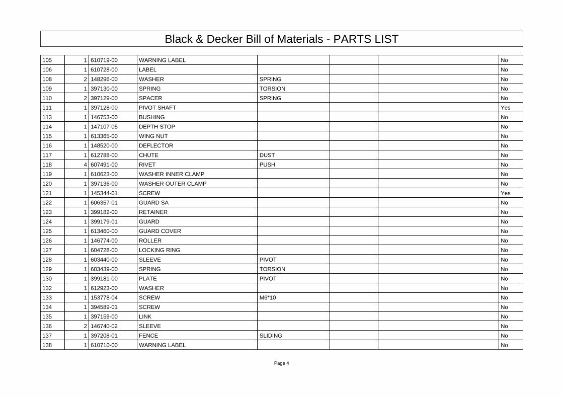
Black & Decker Bill of Materials - PARTS LIST
Page 4
105 1 610719-00 WARNING LABEL No
106 1 610728-00 LABEL No
108 2 148296-00 WASHER SPRING No
109 1 397130-00 SPRING TORSION No
110 2 397129-00 SPACER SPRING No
111 1 397128-00 PIVOT SHAFT Yes
113 1 146753-00 BUSHING No
114 1 147107-05 DEPTH STOP No
115 1 613365-00 WING NUT No
116 1 148520-00 DEFLECTOR No
117 1 612788-00 CHUTE DUST No
118 4 607491-00 RIVET PUSH No
119 1 610623-00 WASHER INNER CLAMP No
120 1 397136-00 WASHER OUTER CLAMP No
121 1 145344-01 SCREW Yes
122 1 606357-01 GUARD SA No
123 1 399182-00 RETAINER No
124 1 399179-01 GUARD No
125 1 613460-00 GUARD COVER No
126 1 146774-00 ROLLER No
127 1 604728-00 LOCKING RING No
128 1 603440-00 SLEEVE PIVOT No
129 1 603439-00 SPRING TORSION No
130 1 399181-00 PLATE PIVOT No
132 1 612923-00 WASHER No
133 1 153778-04 SCREW M6*10 No
134 1 394589-01 SCREW No
135 1 397159-00 LINK No
136 2 146740-02 SLEEVE No
137 1 397208-01 FENCE SLIDING No
138 1 610710-00 WARNING LABEL No
Black & Decker Bill of Materials - PARTS LIST
Page 5
140 1 603856-01 LABEL RAIL ADJ. SCREW No
141 1 398472-00 SPRING TORSION No
142 1 397150-00 LEVER LOCK No
143 1 152852-00 BOLT No
144 1 612008-00 SCREW PATCH LOCK Yes
145 1 612004-00 KNOB LOCK PIN No
146 1 613497-00 THRUST PLATE No
149 1 397186-00 TERMINAL BLOCK No
150 1 330036-17 ROLL PIN No
151 1 397176-00 SPRING No
152 1 397175-00 CAP BATTERY EJECTION No
153 1 397188-00 LEVER LOCK-OFF No
154 1 397189-00 SPRING No
155 4 330019-13 SCREW M4*19 No
156 1 397187-00 BUTTON No
800 1 610817-00 GREASE THERMAL No
800 1 790206-00 GREASE No
800 1 93488-00 GREASE No
866 1 487134-00 BATTERY PACK NiCAD 2.0ah - DW No
866 1 578671-01 BATTERY PACK NIMH 3.0ah No
867 1 608262-00 CAP BATTERY No
871 1 487135-00 CHARGER SA NiCAD 2.0ah GB No
871 1 487135-01 CHARGER SA NiCAD 2.0ah QW No
871 1 578672-00 CHARGER SA NiMH 3.0ah GB No
871 1 578672-01 CHARGER SA NiMH 3.0ah QW No
876 1 398763-01 MOTOR SA No

R11368en.rtf
R11368
DW017 Mitre Saw Type 1
3 Adjust so that the blade is square to the fence within ±0.1° when the ZERO miter detent is engaged.11 Apply Loctite 271 (or Loxeal 86-72) to stud before assembly into table. Stud must be bottomed in
hole.19 Rod to be adjusted so the table (Item 10) will not rotate with a 9Kg force applied while not in detent.
Miter handle (Item 17) must be locked.22 Adjust the 0°, 33.85° and 45° bevel stop screws to within ±0.1°23 Adjust so that the center mark points at 0±0.1°24 Adjust center mark to the proper angle within ±0.1°28 Adjust nut to remove clearance between table and base. Table must rotate freely.40 Adjust to remove all clearance between rail and guides.55 Bevel handle should be ± 15° to horizontal.77 Date Code located on bottom.97 Place small amount of thermal grease (Item 800) between module and arm (Item 60).144 Tighten until seated then loosen until motor arm moves freely. Do not loosen more than ¼ turn.
LUBRICATION:1 Fill grooves in base and lubricate the center post with Lubriplate (Item 800).10, 35, 42, 111 Grease mating surfaces with Lubriplate (Item 800).
Fill gear case with 30 grams of grease.
TORQUES:
33 Torque fence screws to 26 – 42Nm in the sequence shown.68 Torque to 6.2-6.8Nm.121 Torque to 17.3 – 22.7Nm.

DW017 24Volt Miter SawCheck Procedure for Unit wiring
A number of early units were built with the motor 180° out of line. Theconsequence of this is that the blade runs backwards, to repair this fault themotors on these units were rewired. If a unit comes in for repair and the wiresto the motor need to be disconnected then the check detailed below will assistin re-wiring the unit. If the motor is changed, then irrespective of how it wasoriginal wired up, the unit must have the new motor fitted in the correctorientation and the machine wired up in the correct way.
1. Determine if the unit has motor correctly mounted. This can beaccomplished by feeling the motor cover plate to see if the motor hasbeen mounted correctly. To make this easier, release the head lock toraise the head. If there are notches on the cover plate, then the motor isincorrectly mounted.
Correct assembly
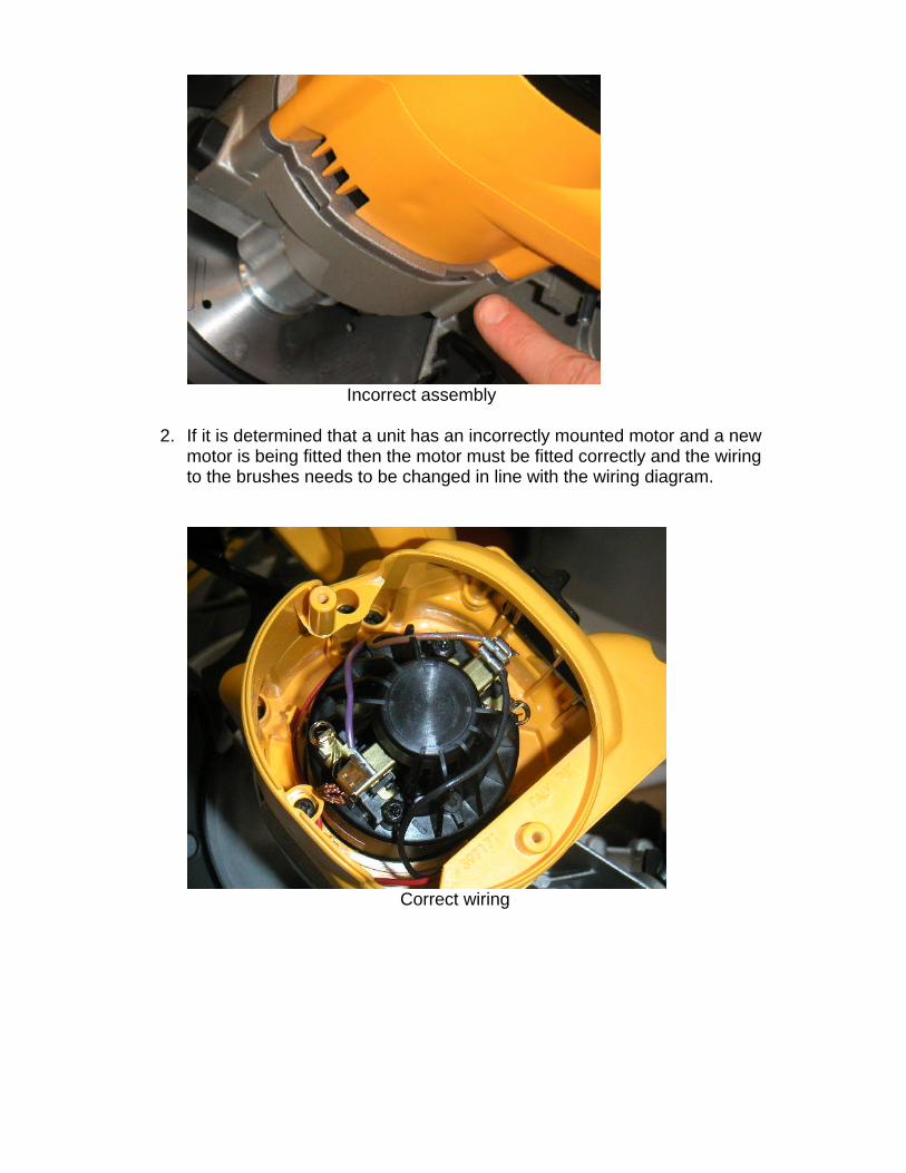
Incorrect assembly
2. If it is determined that a unit has an incorrectly mounted motor and a newmotor is being fitted then the motor must be fitted correctly and the wiringto the brushes needs to be changed in line with the wiring diagram.
Correct wiring
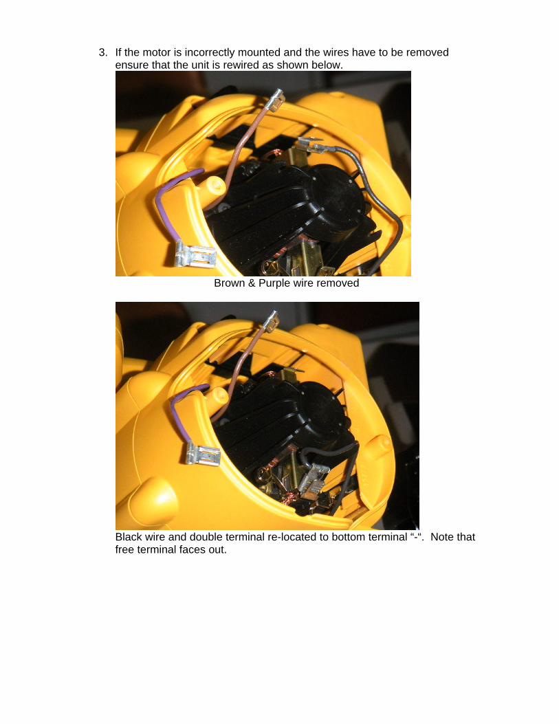
3. If the motor is incorrectly mounted and the wires have to be removedensure that the unit is rewired as shown below.
Brown & Purple wire removed
Black wire and double terminal re-located to bottom terminal “-“. Note thatfree terminal faces out.
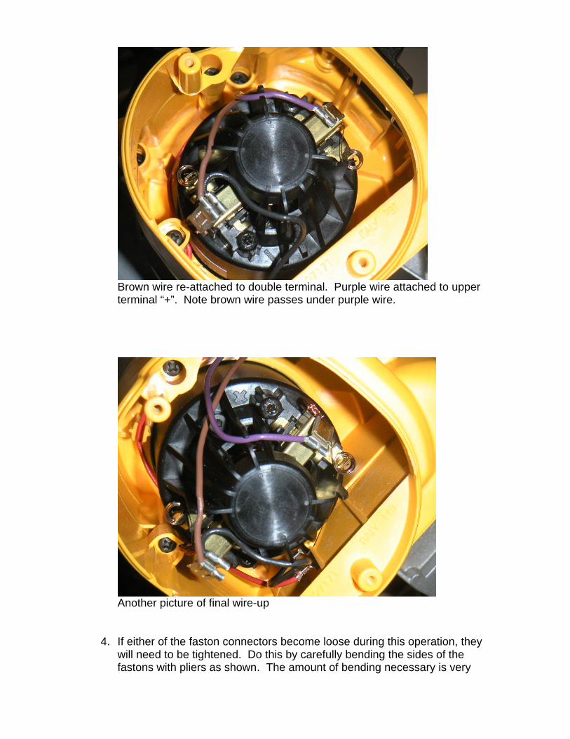
Brown wire re-attached to double terminal. Purple wire attached to upperterminal “+”. Note brown wire passes under purple wire.
Another picture of final wire-up
4. If either of the faston connectors become loose during this operation, theywill need to be tightened. Do this by carefully bending the sides of thefastons with pliers as shown. The amount of bending necessary is very

little. Do not over bend, or the terminal will be very difficult to re-assemble.
5. After the repair is completed, reattach the end cap, return the saw to zerobevel, and make sure to secure the bevel lock. Insert the battery and testfor correct rotation of blade.

New Parts
24V MITRE SAWDW017
Part Number Part Description
ROLL PIN330036-17
HOUSING & COVER397169-00
LATCH BUTTON397172-00
END CAP397174-00
CAP397175-00
SPRING397176-00
SWITCH397182-00
HOUSING & COVER397183-00
TERMINAL BLOCK397186-00
BUTTON397187-00
LEVER LOCK-OFF397188-00
SPRING397189-00
LEAD BROWN397191-00
LEAD PURPLE397192-00
GEARCASE COVER SA397210-01
FIELDCASE398762-00
MOTOR SA398763-01
BOOT605151-00
ARMATURE SA605446-00
BRUSH BOX607230-01
CAP608262-00
WARNING LABEL610719-00
LABEL610728-00
SCREW98094-35
07 March 2003 Page 1 of 2P1ant: TAT
Please DO NOT order any parts until a Service Change Note is published.

TYP.
WWW.2helpU.com 06 - 03 - 03E13560
DW017 1