dust extraction system
TRANSCRIPT

8/7/2019 dust extraction system
http://slidepdf.com/reader/full/dust-extraction-system 1/13
SHAPA Technical Bulletin No.6
10 Key Steps for Comparing Dust Extraction System Proposals
Page 1 of 13 Oct. 2002
SHAPA TECHNICAL BULLETIN No.6.
10 KEY STEPS
FOR COMPARING
DUST EXTRACTION SYSTEM PROPOSALS

8/7/2019 dust extraction system
http://slidepdf.com/reader/full/dust-extraction-system 2/13
SHAPA Technical Bulletin No.6
10 Key Steps for Comparing Dust Extraction System Proposals
Page 2 of 13 Oct. 2002
Ten Key Steps
For
Comparing Dust Extraction System Proposals
John Whitehead – General Secretary, SHAPA
Introduction
Wherever solid particulate is being handled, processed or stored or is created, as a bi-product of a process such as machining or finishing, dust is usually generated.
This dust needs to be controlled to prevent environmental damage and risks to health.In general there are the 4 means of controlling dust as listed below in order of best
effect:
1) Preventing the creation of the dust in the first place by using a different
process or material
2) Containing the dust
3) Suppressing the dustOr
4) Extracting and collecting the dust
The first 3 approaches should always be given careful consideration as they do offer
the most effective ways of solving the problem and are often the most economic. Dust
extraction should only be considered as a last resort if none of the other methods are
feasible.
In many instances, however, none of the first 3 preferred means are either operationally practical or compatible with the specification and/or quality
requirements of the final product and the extraction and collection means is the only
viable solution.
This paper outlines the 10 Key Areas that purchasers should focus on in their
assessment and comparison of Dust Extraction System proposals.
1. Suppliers Assessment of Your Requirement
The whole process starts with the recognition that there is a dust problem that needs to
be handled and a number of potential suppliers are contacted.
The first measure of a potential supplier is the initial reaction you obtain from them
and their willingness to provide a solution to your problem. Some suppliers will try to
‘solve’ the problem from their office but this is seldom satisfactory unless your requirement is merely for a single piece of equipment such as a silo venting filter
rather than an extraction system.
To be able to fully and accurately assess your requirement a site visit by a competent
dust control engineer is essential.
Once the engineer is on site you should ensure that you are given the opportunity tofully describe the problem as you see it and give the engineer as much information as

8/7/2019 dust extraction system
http://slidepdf.com/reader/full/dust-extraction-system 3/13
SHAPA Technical Bulletin No.6
10 Key Steps for Comparing Dust Extraction System Proposals
Page 3 of 13 Oct. 2002
possible. Even applications that appear to be identical can require different solutions
when all aspects of the specific application and local conditions are properly
considered.
Do not allow the engineer to offer a solution until you are satisfied that he has all the
relevant information concerning your particular application and is not making
assumptions based either on previous work he has done or on the product he wants tosell.
Once the engineer has obtained all of the information he should be able to give you an
outline of what he is going to propose as a solution to your dust problem. This should
include: -
1. Method of dust capture2. Type and position of dust collector
3. Method of collection of dust for disposal4. Any health and safety issues and installation requirements.
Following the site visit you should receive a quotation for the system from which you
should be able to assess the next key areas.
2. Dust Capture Method
The engineer, from his observations of the application, must design a suitable system
to solve the dust problem. The solution should utilise the minimum amount of ‘control
air’ possible to achieve a good level of dust control as in general costs involved are
directly related to the quantity of control air employed.
The solution may take the form of the provision of localised hoods at each dust
generation point or the use of an enclosure around a number of these points. In some
cases a combination of these two methods of approach may be considered to be the
best solution.
Fig.1 Example of Local proximity hood Fig.2 Example of an Enclosure
The use of a local proximity hood applied to drum filling operation is shown in fig.1.
This hood is designed to pull a curtain of air over the top of the drum to capture the
dust created while materials are being tipped into the drum.
8/7/2019 dust extraction system
http://slidepdf.com/reader/full/dust-extraction-system 4/13
SHAPA Technical Bulletin No.6
10 Key Steps for Comparing Dust Extraction System Proposals
Page 4 of 13 Oct. 2002
The hood is shaped around the periphery of the drum to ensure that the hood face is as
close as possible to any possible point of dust escape, as the effectiveness of an open
face hood diminishes rapidly as the distance from the face increases.
A simple formula for calculating the quantity of air (Q) M³/ min required to provide a
capture velocity (V) M/min for a dust at a varying distance (X) M from an open hood
of face area (A) M² is:
Q = V (10X² + A)
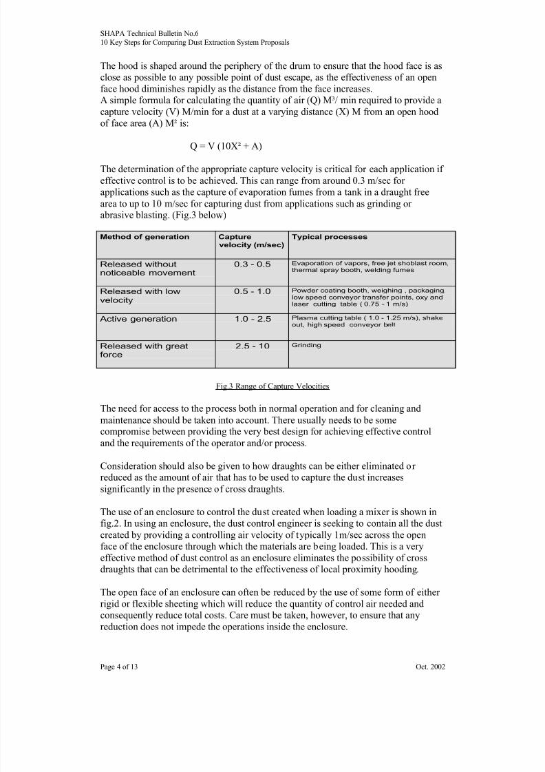
The determination of the appropriate capture velocity is critical for each application if
effective control is to be achieved. This can range from around 0.3 m/sec for
applications such as the capture of evaporation fumes from a tank in a draught free
area to up to 10 m/sec for capturing dust from applications such as grinding or abrasive blasting. (Fig.3 below)
Fig.3 Range of Capture Velocities
The need for access to the process both in normal operation and for cleaning andmaintenance should be taken into account. There usually needs to be somecompromise between providing the very best design for achieving effective control
and the requirements of the operator and/or process.
Consideration should also be given to how draughts can be either eliminated or reduced as the amount of air that has to be used to capture the dust increases
significantly in the presence of cross draughts.
The use of an enclosure to control the dust created when loading a mixer is shown in
fig.2. In using an enclosure, the dust control engineer is seeking to contain all the dust
created by providing a controlling air velocity of typically 1m/sec across the open
face of the enclosure through which the materials are being loaded. This is a very
effective method of dust control as an enclosure eliminates the possibility of cross
draughts that can be detrimental to the effectiveness of local proximity hooding.
The open face of an enclosure can often be reduced by the use of some form of either
rigid or flexible sheeting which will reduce the quantity of control air needed and
consequently reduce total costs. Care must be taken, however, to ensure that any
reduction does not impede the operations inside the enclosure.
Method of generation Capture
velocity (m/sec)
Typical processes
Released without
noticeable movement
0.3 - 0.5 Evaporation of vapors, free jet shoblast room,
thermal spray booth, welding fumes
Released with lowvelocity
0.5 - 1.0 Powder coating booth, weighing , packaging,low speed conveyor transfer points, oxy andlaser cutting table ( 0.75 - 1 m/s)
Active generation 1.0 - 2.5 Plasma cutting table ( 1.0 - 1.25 m/s), shakeout, high speed conveyor belt
Released with greatforce
2.5 - 10 Grinding

8/7/2019 dust extraction system
http://slidepdf.com/reader/full/dust-extraction-system 5/13
SHAPA Technical Bulletin No.6
10 Key Steps for Comparing Dust Extraction System Proposals
Page 5 of 13 Oct. 2002
3. Ducting System
The design of the ducting system connecting the extraction points to the dust collector
is a very important factor in the creation of a successful installation. The system
design should take into account: -
1. The type, nature and quantity of dust to be handled.2. The likelihood of internal wear from abrasion
3. The appropriate conveying velocity for the dust concerned to avoid either
excessive power consumption and excessive wear or settlement in the duct. (see
Fig.4 )
4. The need for inspection and cleaning
Fig.4 Range of Conveying Velocities for different types of dusts
The ducting construction should be of sufficient strength and thickness for the
particular application, be dust tight and be adequately supported.
The ducting system should also be properly balanced by means of internal balancing
cones if at all possible or fixable dampers to ensure that the correct quantity of control
air is extracted from each point. An unbalanced system will provide more air than is
required at some points, usually the smaller ones, whilst starving others and thereforeproviding inadequate extraction.
Internal balancing cones are the preferred method as once they are set they giveconsistent and reliable results. Dampers are often moved by operators throwing the
system out of balance and the can be a source of material build up inside the duct.
4. Dust Collectors
There are a number of different types of equipment that can be used to separate the
entrained dust from the conveying airflow. The most common are considered below
outlining their strengths, weaknesses and variations to be considered:
Cyclones
The use of cyclones to provide separation of the entrained dust from the control air is
the traditional and the most basic approach.
Material Conveyed Conveying Velocity in
ducts m/secVapor, gases, fumes,very fine dusts
7.6 - 10.2
Fine dry dusts 15 - 18
Average industrial dusts 18 - 20Coarse particles 18 - 23
Large particles 23 and higher

8/7/2019 dust extraction system
http://slidepdf.com/reader/full/dust-extraction-system 6/13
SHAPA Technical Bulletin No.6
10 Key Steps for Comparing Dust Extraction System Proposals
Page 6 of 13 Oct. 2002
Fig.5 Typical Cyclone
The efficiency of separation provided by typical cyclones is, however, not particularly
good when fine dust is involved and there is invariably some degree of dust carry over in the cleaned air discharge. As a result cyclones are normally only used on very
coarse dusts, as a pre-separator prior to a more efficient method of collection or onspecialist applications where the materials or temperatures involved prohibit the use
of other methods. There are also some limited other applications where specially
designed higher efficiency cyclones provide the best solution.
Wet Collectors
Wet Collectors, or scrubbers, are available in a number of designs with the most
commonly used being either the low-pressure induced spray type or the higher-
pressure venturi scrubber.
Fig.6 Induced Spray Wet Collector

8/7/2019 dust extraction system
http://slidepdf.com/reader/full/dust-extraction-system 7/13
SHAPA Technical Bulletin No.6
10 Key Steps for Comparing Dust Extraction System Proposals
Page 7 of 13 Oct. 2002
Wet collectors have the ability to handle moisture-laden air and the collected dust is
delivered from the collector in a wetted form so avoiding a secondary dust problem
but disposal of the collected material in the wet state can be difficult and expensive.
Efficiency is a function of total energy input per m³/hr of air being treated, whether
the energy is supplied to the air or to the water. This means that well-designed
collectors by different manufacturers will provide similar efficiency if equivalentpower is utilised.
One of the commonest uses of wet collectors is to handle potentially explosive dust
from operations such as the grinding of aluminium, magnesium or titanium.
Generally speaking wet collection is now only used for applications where it is notpossible to use dry collection.
Fabric Filters
Fabric filters are the most common type of dust collectors currently used. They can
either be intermittently rated or, more commonly, continuously rated.
• Intermittently rated
In this type of filter, as illustrated in Fig.7, the air is drawn into the hopper of
the collector and a coating of dust is built up on the filter fabric as the air
passes through it towards the fan and the ‘clean air’ discharge at the top of the
collector. A mechanical shaker mechanism has to be operated periodically,after typically 4 hours operation, to shake the dust that has built up on the
fabric down into a dust collection device.
Fig.7 Typical Intermittently Rated Dust Collector
To achieve effective filter bag cleaning the mechanical shaking procedure can
only be done under no flow conditions so the dust collector has to be taken out
of service for a few minutes to allow this operation to be carried out, unless an
elaborate and costly alternating system that closes off portions of the filter is
built into the system.

8/7/2019 dust extraction system
http://slidepdf.com/reader/full/dust-extraction-system 8/13
SHAPA Technical Bulletin No.6
10 Key Steps for Comparing Dust Extraction System Proposals
Page 8 of 13 Oct. 2002
Intermittently rated filters are therefore only normally used on applications,
such as manually operated processes, where the system can be stopped
periodically. This type of collector usually also relies on an operator to stop
the process and initiate the shaking sequence.
• Continuously Rated
These have been the most commonly used type of dust collectors over the last
20/30 years. Unlike the intermittently rated type these dust collectors do not
have to be stopped to allow the dust accumulated on the filter fabric to be
cleaned down. Continuously rated filters are cleaned during operation by
means of either reverse jet compressed air or low-pressure reverse flow.
The reverse jet cleaning type are the most commonly used for general work
with the reverse air type being used to advantage sometimes in specific
applications where high temperatures or highly abrasive materials areinvolved. The less severe cleaning method of the reverse air type of collector
can reduce the risk of corrosion due to dew point conditions and also reducefabric wear from mechanical abrasion.
Fig.8 Typical reverse jet cleaned dust collector
There are a number of different designs of reverse jet dust collector. Some use
cylindrical filter bags (socks) and others such as the one illustrated in Fig.8 use
flat filter envelopes (pads).
In the illustrated collector the air is drawn into the inlet at the top of the frontof the collector, it passes through the filter pads, that are mounted horizontally,
leaving the dust on the outside of the pad with the ‘clean air’ passing throughthe internal centre of the pad to the outlet on the rear of the collector. The filter
pads are cleaned in sequence with compressed air that is introduced into thecentre of each pad.

8/7/2019 dust extraction system
http://slidepdf.com/reader/full/dust-extraction-system 9/13
SHAPA Technical Bulletin No.6
10 Key Steps for Comparing Dust Extraction System Proposals
Page 9 of 13 Oct. 2002
• Fabric Filter Specification
The type of fabric and the filtration velocity are important issues to beconsidered when Fabric Filters are being specified.
The choice of fabric and filtration velocity, (the speed that the air passes
through the filtering fabric), are determined from consideration of thefollowing factors: -
• Dust characteristics
• Type
• Particle Size and shape
• Dust loading
• Temperature
• Chemical properties
• Application characteristics
• Source of dust• Emission limit to be achieved
• Operating cycle
Fig.9 Guide to Properties of Common Synthetic Fibres
Polyproylene Polyester Dralon Ryton Nomex PTFE P84
Maximum cont. dry 100 150 140 190 200 250 260
Maximum surge temp. 110 180 150 20 250 280 300
Maximum cont. moist 100 100 125 190 180 240 240
Hydrolysis resistance E P E E P E F
Melting point or decomposition temp.
160 240 250 285 400 290 400+
Abrasion resistance G E M M E F E
Acids E G G E F E G
Alkalies E F F E G E P
Oxidising Agents F G G P G E M
Solvents G E G E E E E
P = Poor F = Fair M = Medium G =Good E = Excellent
Typical filtration velocities for the different types of fabric filters are normally
in the following ranges depending on the factors listed above:
Intermittently rated collector 0.6 to 1.8 M/min
Reverse jet continuously rated collector 1.5 to 3.5 M/min
Reverse Air continuously rated collector 0.6 to 1.5 M/min

8/7/2019 dust extraction system
http://slidepdf.com/reader/full/dust-extraction-system 10/13
SHAPA Technical Bulletin No.6
10 Key Steps for Comparing Dust Extraction System Proposals
Page 10 of 13 Oct. 2002
It is critical that this assessment is done correctly as changing the filter media
and/or adding addition fabric area can be very expensive. Sometimes it may
even be impossible to extend the collector to allow addition fabric area to be
provided.
If the collector has been sized with a filtration velocity that is too high the
result will be a higher than design operating pressure which will in turn lead toan insufficient volume of air to control the dust generated by the application
and a reduction in fabric life.
o Cartridge Filters
The use of reverse jet cleaned dust collectors fitted with filter cartridges, rather thanfilter bags, has increased significantly over the last decade as cartridge technology has
developed.
Cartridge filters, whilst not as versatile as fabric filters, are very compact whichallows them to handle a given air volume within a smaller cabinet than the equivalent
fabric filter. They are also capable of achieving guaranteed low emission levels due tothe rigid construction of the cartridge element and the lack of media movement when
bearing pulse cleaned.
Applied to suitable applications cartridge collectors provide a very efficient and cost
effective solution. They are widely used on applications where small particles are
involved such as laser cutting, welding, pigments and powder spray.
Filtration velocities are normally in the range of 0.3 to 1.5M/min.
o Explosive Dusts
Many dusts are potentially explosive. This needs to be considered when choosing the
type of collector to be used and the construction specification of the collector and
ducting system.
Explosive dusts can be safely handled by the use of suppression, containment or venting methods. Many factors need to be considered when choosing which is the
most appropriate for an application and is a whole topic in its own right which cannotbe adequately covered in this paper. (see reference list)
5. Dust Disposal Method
The collected dust has to be removed from all dust collectors. There are numerousways in which this can be done and care must be taken to ensure that the correct one
is selected to suit both your application and your working practices.

8/7/2019 dust extraction system
http://slidepdf.com/reader/full/dust-extraction-system 11/13
SHAPA Technical Bulletin No.6
10 Key Steps for Comparing Dust Extraction System Proposals
Page 11 of 13 Oct. 2002
Some of the questions to be answered are: -
Does the collected dust need to go back into the process?
If so,
At what point in the process and by what means?
By: gravity, screw conveyor, rotary valve, pneumatically or other method?
Or, Is the dust waste to be disposed of?
If so,
What is it to be held in? Bin, bag, skip or other container?
How will the dust be later removed from this container?
Can the dust collector be stopped to allow the dust to be removed?
If not, how can the container be isolated from the collector to allow dustremoval?
Consideration of the answers to these questions should allow the dust control engineer
to provide a suitable method which will take care of the collected without creatingeither a secondary dust problem or an unwanted disruption to the process
6. Operator Friendliness
An effective dust extraction system should remove the dust problem and ensure good
working conditions without significantly inhibiting access to the operation or
inconveniencing the operators.
The dust control engineer will have failed, even if the system he puts in eliminates the
dust problem, if the operators do not freely adopt it because it makes their tasks more
difficult. There is often a need for some compromise between ideal control conditions
and operator needs and the dust control engineer should take time to initially listen to
the operators to determine their needs and later to explain the benefits of the new
system.
7. Emission Levels and Guarantees
Different types of dust collectors are capable of achieving different levels of emissionwhen applied correctly to an application so care should be taken to ensure that the
right type of collector is used and that it is correctly sized.
Typical levels of emission achieved by different types of correctly sized dust
collectors (in mg/M³) are:
Cyclone (very dependant on dust size) > 100 - 200
Wet Collector (dependant on dust size) > 100 - 200
Mechanical shake filter < 10 - 20
Reverse jet bag filter < 5 - 10
Cartridge filter < 2 - 3

8/7/2019 dust extraction system
http://slidepdf.com/reader/full/dust-extraction-system 12/13
SHAPA Technical Bulletin No.6
10 Key Steps for Comparing Dust Extraction System Proposals
Page 12 of 13 Oct. 2002
To determine which type of duct collector is required for your application you should:
Decide whether you want to discharge the cleaned air back into the
workplace, to save on heating costs, or directly to the outside environment.
(Limits for recirculation are lower than for discharging to atmosphere)
Ascertain the requirement of the legal regulations.(see reference list)
Determine whether the collector being offered can reliably achieve thelevel required without the need for further secondary filtration.
Consider the implications of failure. Secondary filtration may be required
to act as a ‘policeman filter’ to prevent dust release if the primary filter
fails.
8. Maintenance and After Sales
Other considerations when deciding on which dust extraction system to purchaseshould be: -
How easy the system is to maintain
How much downtime is required for maintenance Frequency of maintenance needed
Availability of spares
Cost of bag/cartridge change
Frequency of need to change bags/cartridges
Suppliers ability and availability for troubleshooting
The dust extraction system is an integral part of your production and needs to be kept
running efficiently. Its reliability and the real costs of keeping it in good condition are
critical and should be borne in mind when making the initial purchase decision.
9. Total Cost of Ownership
The real cost of any dust extraction system is not merely the initial price. The total
cost to the purchaser is this initial cost plus the costs involved in running the systemover its complete life cycle.
It is very short sighted to purchase the lowest priced solution that you consider will
solve the problem without taking into account the following in addition to the pointsalready discussed: -
The design standards employed
The materials of construction
All aspects of maintenance Costs of consumable and replacement parts
The implications of malfunction
10. Supplier Assessment
Whilst it is obviously important to select a solution that will provide an effective
answer to the dust problem at an acceptable competitive cost in the lead time required,
time should also be taken to assess the supplier.

8/7/2019 dust extraction system
http://slidepdf.com/reader/full/dust-extraction-system 13/13
SHAPA Technical Bulletin No.6
10 Key Steps for Comparing Dust Extraction System Proposals
Page 13 of 13 Oct. 2002
The purchaser should take into consideration: -
Company size and available resources
Company history
Financial strength and stability
Whether the supplier has done any similar installations
Customer references
Purchasers need to assure themselves that the company they are about to buy from has
the knowledge and resources to solve the problem and support the installation in the
long term.
Conclusion
There are many facets to the purchase of a dust extraction system if you are to end upwith an efficient, reliable and cost effective system that will give satisfactory
performance over a long period. The wise purchaser will take all the issues raised inthis paper into consideration before finally deciding on which system to buy.
Remember that once a system has been installed it can be very expensive and
disruptive to alter if it does not give the level of performance that you need.
References
For all aspects of dust extraction and air movement
‘Industrial Ventilation’ by the American Conference of Governmental
Industrial Hygienists Inc, 6500 Glenway Ave, Building D-7, Cincinnati, Ohio
45211-4438
For information on Dust Explosions
‘Dust Explosion Prevention & Protection – a practical guide’ by John Barton,
published by IChemE, Davis Building, 165-189 Railway Terrace, Rugby,
Warwickshire, CV21 3HQ
For UK Occupational Exposure Limits‘EH40 - Occupational Exposure Limits’ by Health and Safety Executive from
HMSO
Acknowledgement
Donaldson Torit DCE, Leicester for assistance and providing chart material for inclusion in this paper.
The information included in this paper is based on the writer’s years of experience inthe dust control industry and is offered as a guide to any prospective purchaser of dust
extraction equipment. No responsibility or liability can be taken for any specific
application.
© Copyright, John Whitehead, General Secretary SHAPA Ltd, October 2002