ds/en 1990 dk na:2013 english 6 of 16 . ds/en 1990 dk na:2013 are linearly proportional to the...
TRANSCRIPT

Page 1 of 16 DS/EN 1990 DK NA:2013
DS/EN 1990 DK NA:2013
National Annex to
Eurocode: Basis of structural design _______________________________________________________________________
Foreword
This National Annex (NA) is a consolidation and revision of DS/EN 1990 DK NA 2010 and DS/EN
1990 DK NA Addendum 1:2010 and supersedes these documents as of 2013-05-15. For a transition
period until 2013-09-01, this National Annex as well as the previous National Annex will be appli-
cable. This NA does not deal with bridges and therefore EN 1990/A1:2005 and EN
1990/A1/AC:2010 have not been taken into consideration.
In addition to the consolidation and editorial changes, the contents of Table A.1.1 DK NA regarding
natural actions, clause A.1.3 and Annex F (2) have been considerably modified.
Previous versions, addenda and an overview of all National Annexes can be found at
www.Eurocodes.dk
This national Annex (NA) lays down the conditions for the implementation in Denmark of EN 1990
for construction works in conformity with the Danish Building Act or the building legislation. Other
parties can put this NA into effect by referring thereto.
The national choices may be in the form of nationally applicable values, an option between methods
given in the Eurocode, or the addition of complementary information.
This NA includes:
an overview of possible national choices and complementary information;
national choices;
complementary (non-contradictory) information which may assist the user of the Eu-
rocode.
The numbering refers to the clauses containing choices and/or complementary information. To the
extent possible, the heading/subject is identical to the heading of the clause, but as references are at
a more detailed level than the headings, the heading/subject has in several cases been made more
explicit.

Page 2 of 16 DS/EN 1990 DK NA:2013
Overview of possible national choices and clauses containing comple-
mentary information
The list below identifies the clauses where national choices are possible and the applicable/not ap-
plicable informative annexes. Furthermore, clauses giving complementary information are identi-
fied. Complementary information is given at the end of this document.
Clause Subject Choice
Complementary
information
A1.1(1) Field of application (design working life) Unchanged:
A1.2.1(1) Combinations of actions, General
Modifications of combinations of actions
for geographical reasons
Unchanged
A1.2.2 / Table
A1.1 Values of factors National
choice
A1.3.1(1)/
Table
A1.2(A)-(C)
Design values of actions in persistent and
transient design situations
National
choice
A1.3.1(5) Design values of actions in persistent and
transient design situations: Choice of
approach regarding geotechnical actions
National
choice
A1.3.2 (Table
A1.3)
Design values of actions in accidental
and seismic design situations
National
choice
A1.4.2(2) Serviceability criteria National
choice
A1.4.3 Deformations and horizontal displace-
ments
Complementary
information
A1.4.4 Vibrations National
choice
Annex B Management of structural reliability for
construction works
Complementary
information
Annex C Basis for partial factor design and relia-
bility analysis
Complementary
information
Annex D Design assisted by testing Complementary
information
Annex E Robustness Complementary
rules
Annex F Partial factors for resistance Complementary
rules
NOTE Unchanged: Recommendations in the Eurocode are followed.
COPYRIGHT © Danish Standards Foundation. Not for commercial use or reproduction. DS/EN 1990 DK NA:2013 Engelsk udgave/English version
Page 3 of 16 DS/EN 1990 DK NA:2013
National choices
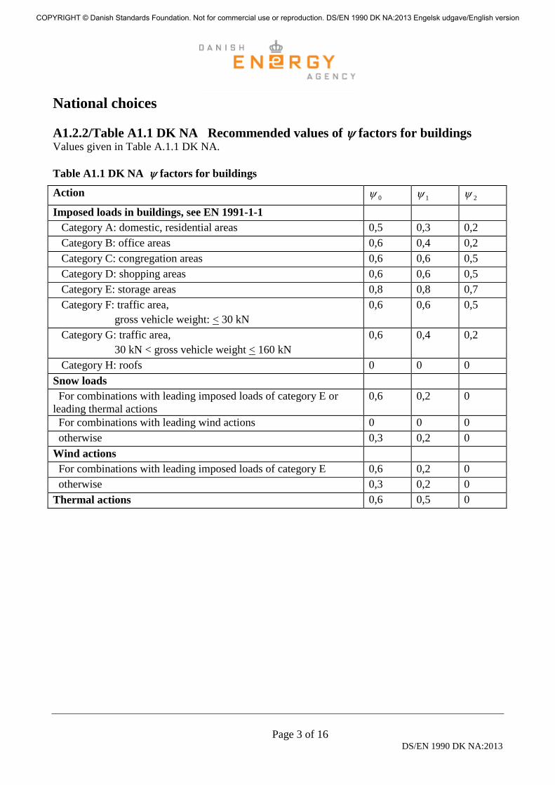
A1.2.2/Table A1.1 DK NA Recommended values of factors for buildings Values given in Table A.1.1 DK NA.
Table A1.1 DK NA factors for buildings
Action 0 1 2
Imposed loads in buildings, see EN 1991-1-1
Category A: domestic, residential areas 0,5 0,3 0,2
Category B: office areas 0,6 0,4 0,2
Category C: congregation areas 0,6 0,6 0,5
Category D: shopping areas 0,6 0,6 0,5
Category E: storage areas 0,8 0,8 0,7
Category F: traffic area,
gross vehicle weight: < 30 kN
0,6 0,6 0,5
Category G: traffic area,
30 kN < gross vehicle weight < 160 kN
0,6 0,4 0,2
Category H: roofs 0 0 0
Snow loads
For combinations with leading imposed loads of category E or
leading thermal actions
0,6 0,2 0
For combinations with leading wind actions 0 0 0
otherwise 0,3 0,2 0
Wind actions
For combinations with leading imposed loads of category E 0,6 0,2 0
otherwise 0,3 0,2 0
Thermal actions 0,6 0,5 0
COPYRIGHT © Danish Standards Foundation. Not for commercial use or reproduction. DS/EN 1990 DK NA:2013 Engelsk udgave/English version
Page 4 of 16 DS/EN 1990 DK NA:2013
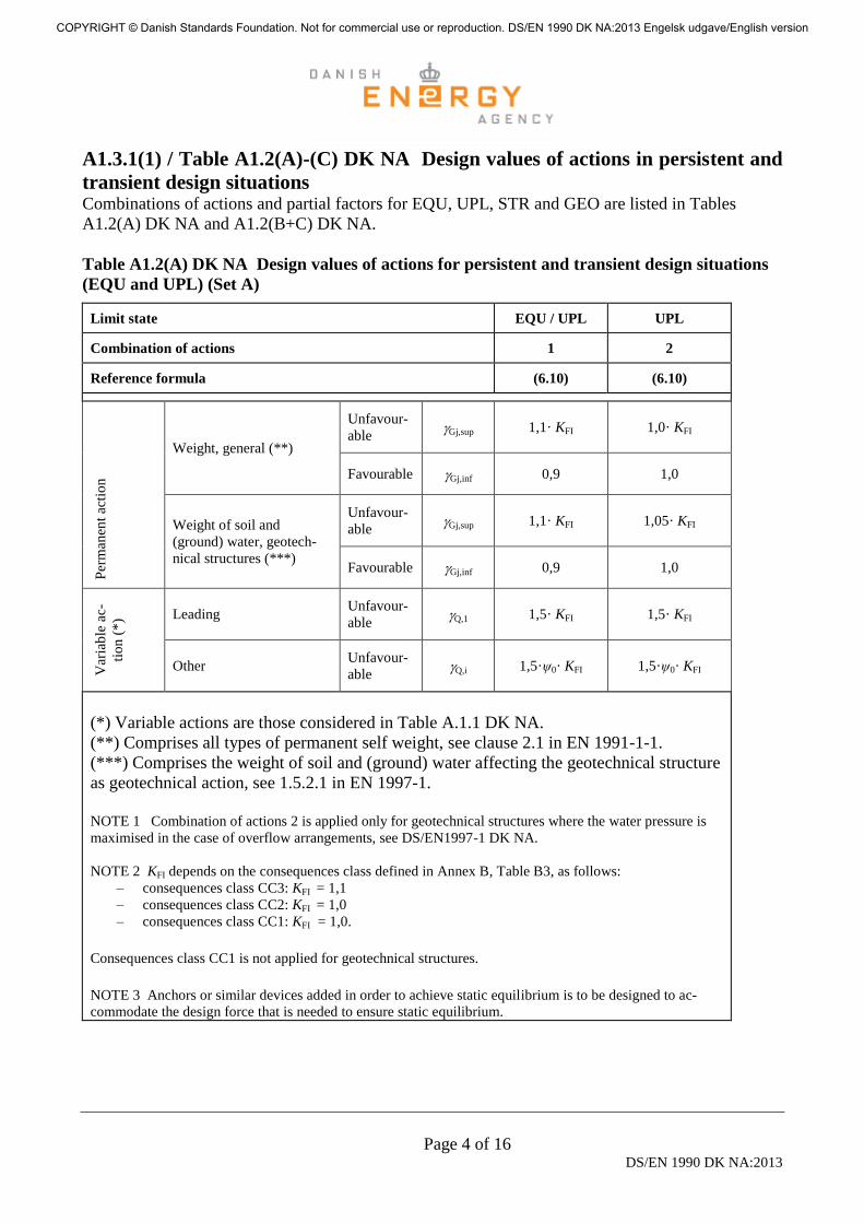
A1.3.1(1) / Table A1.2(A)-(C) DK NA Design values of actions in persistent and
transient design situations Combinations of actions and partial factors for EQU, UPL, STR and GEO are listed in Tables
A1.2(A) DK NA and A1.2(B+C) DK NA.
Table A1.2(A) DK NA Design values of actions for persistent and transient design situations
(EQU and UPL) (Set A)
Limit state EQU / UPL UPL
Combination of actions 1 2
Reference formula (6.10) (6.10)
Per
man
ent
acti
on
Weight, general (**)
Unfavour-
able Gj,sup 1,1· KFI
1,0· KFI
Favourable Gj,inf 0,9 1,0
Weight of soil and
(ground) water, geotech-
nical structures (***)
Unfavour-
able Gj,sup 1,1· KFI 1,05· KFI
Favourable Gj,inf 0,9 1,0
Var
iab
le a
c-
tio
n (
*)
Leading Unfavour-
able Q,1 1,5· KFI 1,5· KFI
Other Unfavour-
able Q,i 1,5·ψ0· KFI 1,5·ψ0· KFI
(*) Variable actions are those considered in Table A.1.1 DK NA.
(**) Comprises all types of permanent self weight, see clause 2.1 in EN 1991-1-1.
(***) Comprises the weight of soil and (ground) water affecting the geotechnical structure
as geotechnical action, see 1.5.2.1 in EN 1997-1.
NOTE 1 Combination of actions 2 is applied only for geotechnical structures where the water pressure is
maximised in the case of overflow arrangements, see DS/EN1997-1 DK NA.
NOTE 2 KFI depends on the consequences class defined in Annex B, Table B3, as follows:
– consequences class CC3: KFI = 1,1
– consequences class CC2: KFI = 1,0
– consequences class CC1: KFI = 1,0.
Consequences class CC1 is not applied for geotechnical structures.
NOTE 3 Anchors or similar devices added in order to achieve static equilibrium is to be designed to ac-
commodate the design force that is needed to ensure static equilibrium.
COPYRIGHT © Danish Standards Foundation. Not for commercial use or reproduction. DS/EN 1990 DK NA:2013 Engelsk udgave/English version

Page 5 of 16 DS/EN 1990 DK NA:2013
Table A1.2(B+C) DK NA Design values of actions for persistent and transient design situa-
tions (STR/GEO) (sets B and C)
Limit state STR/GEO STR
Combination of actions 1 2 3 4 5
Reference formula (6.10a) (6.10b) (6.10a) (6.10b) (6.10a)
Partial factors for actions
Per
man
ent
acti
on
Weight, general (**)
Unfa-
vourable G;sup·KFI 1,2·KFI
1,0·KFI
1,2 1,0 1,0
Favoura-
ble G;inf 1,0 0,9 1,0 0,9 1,0
Weight of soil and
(ground) water, ge-
otechnical structures
(***)
Unfa-
vourable G;sup 1,0 1,0 1,0 1,0 1,0
Favoura-
ble G;inf 1,0 1,0 1,0 1,0 1,0
Vari
able
ac-
tion
(*)
Leading Unfa-
vourable Q,1·KFI 0 1,5·KFI 0 1,5 0
Other Unfa-
vourable Q,i·KFI 0 1,5·ψ0·KFI 0 1,5·ψ0 0
Coefficient applied to partial factors for strength
parameters and resistance
Structural materials,
cf. EN 1992 - 1996 and 1999 γ0
1,0 1,0 KFI KFI 1,2 KFI
Soil parameters and resistance,
cf. EN 1997-1 1,0 1,0 KFI KFI
1,0
(γM = γR = 1,0)
(*) Variable actions are those considered in Table A.1.1 DK NA.
(**) Comprises all types of permanent self weight, see clause 2.1 in EN 1991-1-1.
(***) Comprises the weight of soil and (ground) water affecting the geotechnical structure as geotechnical action, see
1.5.2.1 in EN 1997-1.
NOTE 1 Equations 6.10a and 6.10b are applied for STR as well as GEO. Equation 6.10a relates only to permanent ac-
tions.
NOTE 2 For structures not subject to geotechnical actions, verification can be achieved solely by applying combinations
of actions 1 and 2.
For structures subject to geotechnical actions, verification is to be achieved by applying combinations of actions 1 and 2.
For structures solely subject to geotechnical actions, verification may be achieved by applying combinations of actions 3
and 4 and combination of actions 5.
For KFI = 1,0, combinations of actions 1 and 2 are identical to combinations of actions 3 and 4. For KFI ≠ 1,0, the factor
KFI may be applied to the load effects (internal forces and moments) instead of to the action, provided that the load effects
COPYRIGHT © Danish Standards Foundation. Not for commercial use or reproduction. DS/EN 1990 DK NA:2013 Engelsk udgave/English version
Page 6 of 16 DS/EN 1990 DK NA:2013
are linearly proportional to the associated action.
Geotechnical actions are actions transmitted to the structure by the ground, fill, standing water or ground water. In addi-
tion to the weight, the action from the ground and fill is determined by the strength and deformation properties of the
ground and fill, e.g. expressed as the angle of friction. Examples of geotechnical actions include earth and water pressures
on a wall structure.
NOTE 3 – Coefficient γ0 for the partial factor for strength parameters and resistances is obtained as follows.
For combinations of actions 3 and 4 used for geotechnical structures, cf. EN 1997-1, the KFI factor applies to all relevant
partial factors for the strength parameters and resistance of the ground and for the material strengths and resistances, re-
spectively.
For combination of actions 5 which is used for verification of STR for structural materials forming part of geotechnical
structures, the usual partial factors are applied for structural materials multiplied by 1,2 KFI. For strength parameters and
resistances of the ground, a partial factor of γM = γR =1,0, cf. EN 1997-1, is applied.
NOTE 4 KFI depends on the consequences class defined in Annex B, Table B3, as follows:
– consequences class CC3: KFI = 1,1
– consequences class CC2: KFI = 1,0
– consequences class CC1: KFI = 0,9
Consequences class CC1 is not applied for geotechnical structures.
See also EN 1991 to EN 1999 for values for imposed deformations.
NOTE 5 - The characteristic values of all permanent actions from one source are multiplied by Gj,sup if the total resulting
action effect is unfavourable and by Gj,inf if the total resulting action effect is favourable. As an example all actions origi-
nating from the self weight of the structure may be considered as coming from one source; this also applies if different
materials are involved.
Design values for fatigue actions
(1) Design values for fatigue actions should be determined by applying a partial factor equal to 1,3
for loads where the uncertainty of the individual spans are described by a coefficient of variation of
the magnitude of 30%. For loads where the coefficient of variation is less than 10%, a partial factor
equal to 1,0 is applied. For other values of the coefficient of variation, the partial factor should be
determined by linear interpolation. The coefficient of variation may be stated in connection with the
action specification.
A1.3.1(5) Design values of actions in persistent and transient design situations -
Choice of design approach for geotechnical actions Design Approach 3 is applied, see DS/EN 1997-1 DK NA.
COPYRIGHT © Danish Standards Foundation. Not for commercial use or reproduction. DS/EN 1990 DK NA:2013 Engelsk udgave/English version
Page 7 of 16 DS/EN 1990 DK NA:2013
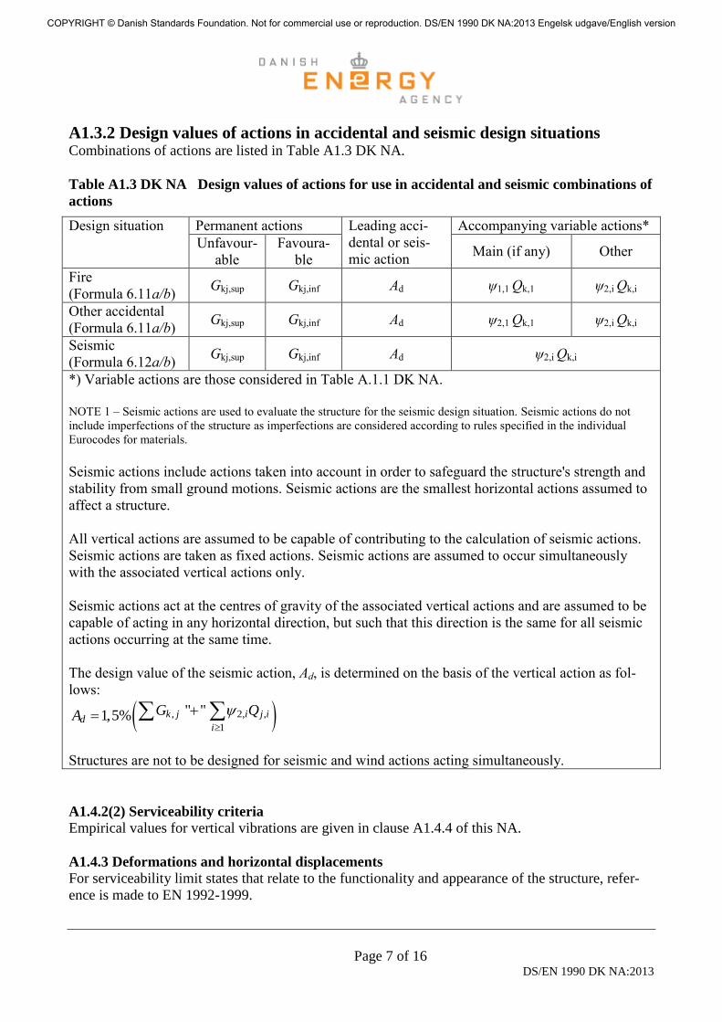
A1.3.2 Design values of actions in accidental and seismic design situations Combinations of actions are listed in Table A1.3 DK NA.
Table A1.3 DK NA Design values of actions for use in accidental and seismic combinations of
actions
Design situation Permanent actions Leading acci-
dental or seis-
mic action
Accompanying variable actions*
Unfavour-
able
Favoura-
ble Main (if any) Other
Fire
(Formula 6.11a/b) Gkj,sup Gkj,inf Ad ψ1,1 Qk,1 ψ2,i Qk,i
Other accidental
(Formula 6.11a/b) Gkj,sup Gkj,inf Ad ψ2,1 Qk,1 ψ2,i Qk,i
Seismic
(Formula 6.12a/b) Gkj,sup Gkj,inf Ad ψ2,i Qk,i
*) Variable actions are those considered in Table A.1.1 DK NA.
NOTE 1 – Seismic actions are used to evaluate the structure for the seismic design situation. Seismic actions do not
include imperfections of the structure as imperfections are considered according to rules specified in the individual
Eurocodes for materials.
Seismic actions include actions taken into account in order to safeguard the structure's strength and
stability from small ground motions. Seismic actions are the smallest horizontal actions assumed to
affect a structure.
All vertical actions are assumed to be capable of contributing to the calculation of seismic actions.
Seismic actions are taken as fixed actions. Seismic actions are assumed to occur simultaneously
with the associated vertical actions only.
Seismic actions act at the centres of gravity of the associated vertical actions and are assumed to be
capable of acting in any horizontal direction, but such that this direction is the same for all seismic
actions occurring at the same time.
The design value of the seismic action, Ad, is determined on the basis of the vertical action as fol-
lows:
, 2, ,
1
" "1,5% k j i j id
i
G QA
Structures are not to be designed for seismic and wind actions acting simultaneously.
A1.4.2(2) Serviceability criteria
Empirical values for vertical vibrations are given in clause A1.4.4 of this NA.
A1.4.3 Deformations and horizontal displacements
For serviceability limit states that relate to the functionality and appearance of the structure, refer-
ence is made to EN 1992-1999.
COPYRIGHT © Danish Standards Foundation. Not for commercial use or reproduction. DS/EN 1990 DK NA:2013 Engelsk udgave/English version

Page 8 of 16 DS/EN 1990 DK NA:2013
A1.4.4 Vibrations - Vertical
Requirements regarding natural frequencies may be based on the empirical values in Table A1.4
DK NA. If a more detailed analysis is carried out, the functioning of the structure will normally be
satisfactory if the variation of the structure's accelerations originating from the stated action does
not exceed the acceleration limit in the table.
The risk of unsatisfactory functioning increases with increasing span and the risk is particularly great
for lightweight or poorly damped structures. For these structures, the natural frequency requirement
in the table does not always result in satisfactory functioning.
Table A1.4 DK NA Empirical values for acceptable natural frequencies and acceleration
limits
Structure Action Normally satisfac-
tory functioning
Often unsatisfacto-
ry functioning
Acceleration limit
in % of the gravity
acceleration
Grandstands, fitness
centres, sports halls
and public premises
Rhythmic
load
caused by
move-
ment of
people
en > 10 Hz en < 6 Hz 10 %
Residential buildings Load
from
walking
en > 8 Hz en < 5 Hz 0,1 %
Office premises Load
from
walking
en > 8 Hz en < 5 Hz 0,2 %
NOTE - Natural frequencies and accelerations are calculated during normal use, where the fluctuating action is typi-
cally considerably less than the action corresponding to the quasi-permanent combination specified in clause 6.5.3 of
EN 1990.
COPYRIGHT © Danish Standards Foundation. Not for commercial use or reproduction. DS/EN 1990 DK NA:2013 Engelsk udgave/English version

Page 9 of 16 DS/EN 1990 DK NA:2013
Complementary (non-contradictory) information
Annex B - Management of structural reliability for construction works Annex B may be used with the following modifications:
- Table B1 (Consequences classes)
- Table B2 (Minimum values for reliability index)
- Clause B4 (Design supervision differentiation)
- Clause B5 is not applied
- Clause B6 is not applied.
Table B1 DK NA Definition of consequences classes
Consequences
class
Consequences of pos-
sible damage
Examples
CC3
High
consequences
class
High risk of loss of
human life, or consid-
erable economic, social
or environmental con-
sequences
– Buildings with several storeys where the height to the
floor of the uppermost storey is more than 12 m
above the ground, if they are often used for accom-
modating people, e.g. residential or office buildings
– Buildings with large spans, if they are often used by
many people, e.g. for concerts, sporting events, theat-
rical performances, or exhibitions
– Grandstands
– Large road bridges and tunnels
– Large masts and towers
– Large silos near a built-up area
– Dams and similar structures where a failure would
result in considerable damage.
CC2
Medium
consequences
class
Medium risk of loss of
human life. Considera-
ble economic, social or
environmental conse-
quences.
Buildings or structures not belonging to CC3 or CC1.
CC1
Low consequenc-
es class
Low risk of loss of
human life, and small
or negligible econom-
ic, social or environ-
mental consequences
– 1 and 2 storey buildings with moderate spans, which
people enter only occasionally, e.g. storage buildings,
sheds and small agricultural buildings
– Small masts and towers, including general street
masts
– Small silos
– Secondary structural members, e.g. partitions, win-
dow and door lintels and cladding
(1) The consequences for adjacent structures and surroundings can be decisive when determining
the consequences class.
(2) Structural members that are not part of the main structure can often be referred to a lower con-
sequences class than the main structure.
COPYRIGHT © Danish Standards Foundation. Not for commercial use or reproduction. DS/EN 1990 DK NA:2013 Engelsk udgave/English version

Page 10 of 16 DS/EN 1990 DK NA:2013
NOTE The main structure is that part of a load-bearing structure the failure of which will have considerable conse-
quences for the reliability and functionality of the entire structure. Examples of structural members that are often con-
sidered not to be part of the main structure include roofs, independent decks, stairways and balconies.
Table B2 DK NA Minimum values for reliability index ß (ultimate limit states) for a 1 year
reference period
Reliability class Minimum values of β
RC3 corresponding to CC3 4.7
RC2 corresponding to CC2 4.3
RC1 corresponding to CC1 3.8
NOTE It is assumed for the determination of the reliability index for RC2 that permanent actions
have a normal distribution and variable actions have a Gumbel distribution. All strength parameters
and model uncertainties should be assumed to have a log-normal distribution. Information on the
choice of coefficients of variation are given in DS/INF 172 Background investigations in relation to
the drafting of National Annexes to EN 1990 and EN 1991 - Reliability verification formats, combi-
nation of actions, partial coefficients, fatigue, snowload, windload, etc.(Available in Danish only).
The reliability index ß is defined in Annex C.
B4 Design supervision differentiation
(1) Design supervision includes checking of the project material relating to the load-bearing struc-
tures, viz. project basis, statistical calculations, drawings/models and execution specifications. The
design brief is the specifications on which the design is based, including the static system and mode
of operation, robustness, fire, material data, action data, etc.
NOTE Design supervision is to contribute to ensuring:
– that the assumptions of the design brief are correct and are used as a basis for the structural design;
– that the assumptions made in the static calculations have been correctly incorporated into any other project material;
– that drawings and execution specifications are adequate for the execution of the load-bearing structures.
(2) Design supervision, except self-checking, is to be documented in accordance with guidelines
drawn up in advance. The method, scope, any points of focus and the results of the design supervi-
sion is to be stated in the documentation.
(3) For all project material, the people responsible for preparation and design supervision, respec-
tively, are to be identified.
(4) For structures in consequences class CC3 where the consequences of failure are particularly
serious, special requirements apply to design supervision.
(5) Examples of structures covered by (4) include:
– buildings with more than 15 storeys above ground level, if they are used for accommodating
persons, e.g. for residential, office or educational buildings;
– hospitals with more than 5 storeys above ground level;
– industrial buildings where failure would have a particularly major impact on society;
COPYRIGHT © Danish Standards Foundation. Not for commercial use or reproduction. DS/EN 1990 DK NA:2013 Engelsk udgave/English version
Page 11 of 16 DS/EN 1990 DK NA:2013
– buildings with large spans, provided they are used by many people, e.g. for concerts, theatri-
cal performances, exhibitions, sporting events, or entertainments;
– grandstands.
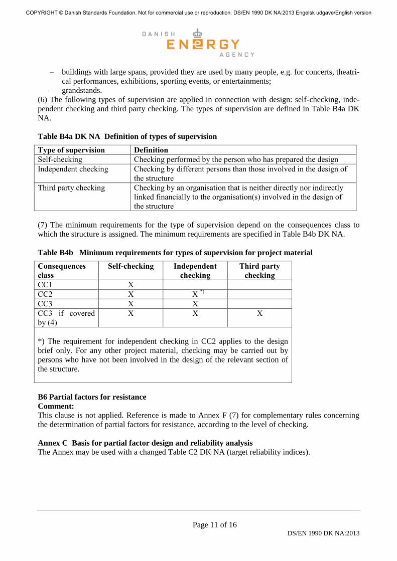
(6) The following types of supervision are applied in connection with design: self-checking, inde-
pendent checking and third party checking. The types of supervision are defined in Table B4a DK
NA.
Table B4a DK NA Definition of types of supervision
Type of supervision Definition
Self-checking Checking performed by the person who has prepared the design
Independent checking Checking by different persons than those involved in the design of
the structure
Third party checking Checking by an organisation that is neither directly nor indirectly
linked financially to the organisation(s) involved in the design of
the structure
(7) The minimum requirements for the type of supervision depend on the consequences class to
which the structure is assigned. The minimum requirements are specified in Table B4b DK NA.
Table B4b Minimum requirements for types of supervision for project material
Consequences
class
Self-checking Independent
checking
Third party
checking
CC1 X
CC2 X X *)
CC3 X X
CC3 if covered
by (4)
X X X
*) The requirement for independent checking in CC2 applies to the design
brief only. For any other project material, checking may be carried out by
persons who have not been involved in the design of the relevant section of
the structure.
B6 Partial factors for resistance
Comment:
This clause is not applied. Reference is made to Annex F (7) for complementary rules concerning
the determination of partial factors for resistance, according to the level of checking.
Annex C Basis for partial factor design and reliability analysis
The Annex may be used with a changed Table C2 DK NA (target reliability indices).
COPYRIGHT © Danish Standards Foundation. Not for commercial use or reproduction. DS/EN 1990 DK NA:2013 Engelsk udgave/English version

Page 12 of 16 DS/EN 1990 DK NA:2013
Table C2 - Target reliability index for class RC2 structural members 1
Limit state Target reliability index
1 year 50 years
Ultimate 4,3 3,3
Fatigue 1,5 to 3,3 2
Serviceability (irreversible) 2,9 1,5 1 See Annex B.
2 Depends on the degree of inspectability, reparability and damage tolerance.
Annex D Design assisted by testing The Annex may be used with the exception of D7.3 and D8.3; see comment.
Comment:
Annex D may be used to check characteristic values and to establish characteristic values and de-
sign values. Clauses D7.3 and D8.3 may not be used as they assume a reliability level correspond-
ing to = 3,8 and application of the design approach in Annex C. Instead reference is made to An-
nex F in which the determination of material partial factors and design values is described.
Annex E Robustness
Complementary rules for the verification of robustness
This Annex may be used for the examination of robustness, see 2.1.4(P) - 2.1.5(P).
(1) A structure is robust:
– when the parts of the structure that are decisive for safety are only slightly sensitive to unin-
tended effects and defects; or
– when there is no extensive failure of the structure if a limited part of the structure fails.
(2) Examples of unintended effects and defects include:
– unforeseen action effects;
– unintended discrepancies between the structure's actual behaviour and the design models
used;
– unintended discrepancies between the implemented project and the project material;
– unforeseen geometrical imperfections;
– unforeseen settlements;
– unforeseen degeneration.
Increased robustness may in certain cases also help to reduce the effects of any gross errors, alt-
hough verification of robustness neither can nor must be regarded as designing against gross error.
(3) Robustness is discussed in more detail in DS/INF 146 Robustness - Background and principles
(available in Danish only).
COPYRIGHT © Danish Standards Foundation. Not for commercial use or reproduction. DS/EN 1990 DK NA:2013 Engelsk udgave/English version
Page 13 of 16 DS/EN 1990 DK NA:2013
(4) The robustness of a structure should be proportional to the consequences of a failure of the
structure. Documentation of robustness is only required for structures in consequences class CC3.
However, for structures in consequences class CC2 an assessment of the robustness is to be made.
The amount of detail of the assessment is to be increased in the case of large spans, large concen-
trated loads, few supports and special (rare or new) types of structures.
(5) A robust structure is achieved by an appropriate choice of materials, general static principle and
construction and by appropriate design of key members. A key member is a restricted part of the
structure that, in spite of its limited extent, is of central importance to the robustness of the structure
such that failure of this member would result in the failure of the whole structure or significant parts
of the structure.
(6) Where documentation of robustness is required, an expert engineering report is to be drawn up
verifying that at least one of the robustness criteria specified in (1) is met. This is achieved
– by verifying that the essential parts of the structure, i.e. key members, have low sensitivity
to unintended effects and defects, cf. (2);
– by verifying that no extensive failure of the structure occurs if a limited part of the structure
fails (loss of a member), see (7)-(8);
– by verifying adequate safety of key members, such that the whole structure to which they
belong attains at least the same level of system safety as an equivalent structure for which
the robustness is documented by verification of adequate safety in the event of the “loss of a
member”.
In addition to the verification itself, the expert engineering report is to contain a critical evaluation
of the construction, including identification of key members and action scenarios.
Verification that the first criterion has been fulfilled is only possible in special cases, and therefore
verification is usually performed by verifying one of the two latter criteria.
(7) Where robustness is verified by ”loss of a member”, the acceptable extent of collapse for build-
ings of up to 15 storeys be taken as: collapse of no more than two floors, extending in this case to
two vertically adjacent floors. At each of the two floors, the extent of collapse is not to affect more
than 15% of the floor space, and no more than 240 m2 per floor and no more than a total area of 360
m2. Adequate resistance is verified in an accidental design situation by using the formula (6.11 a/b),
see Table A1.3 DK NA.
(8) Robustness verified in the event of “loss of a member” may, for residential and grandstand
structures, be regarded as met if it is verified that the damaged structure will continue to constitute a
stable system even if one or more structural members are lost. It is assumed that failure may com-
prise the equivalent of the maximum permissible extent of collapse, cf. (7), including:
– either a floor or roof structure and an arbitrary pillar;
– or a floor or roof structure and an arbitrary piece of wall 3 m in length or width.
COPYRIGHT © Danish Standards Foundation. Not for commercial use or reproduction. DS/EN 1990 DK NA:2013 Engelsk udgave/English version
Page 14 of 16 DS/EN 1990 DK NA:2013
The ability of a structure to retain its coherence after a failure of the specified extent is primarily
conditional upon the damaged structure continuing to constitute a stable system, which means that
the structure or large parts of it are not transformed into a mechanism. If this condition is met, a
rough calculation will be sufficient.
(9) Where robustness is verified by introducing additional reliability of key members, this can usu-
ally be achieved by applying a material partial factor γM, which has been increased by the factor
1,2 compared to the value specified in 6.3.5. With respect to modelling this is equivalent to a sys-
tem with key members in series having the same system reliability as a system of parallel members.
As a general rule, every effort should be made in the design to document the robustness of a struc-
ture as far as possible without the use of increased safety factors on the key members. Where in-
creased safety factors are applied to the key members, it should however be ensured that the re-
sistance of the structure to unintended effects and defects is actually increased.
NOTE For example, the robustness of hinged pillars in a residential building will not generally be sufficiently secured
by applying a factor of 1,2, unless at the same time a structural connection is arranged through each building floor in the
form of a continuous tensile and shear connector in the pillar.
(10) The structural Eurocodes may provide guidelines for adequately ensuring robustness.
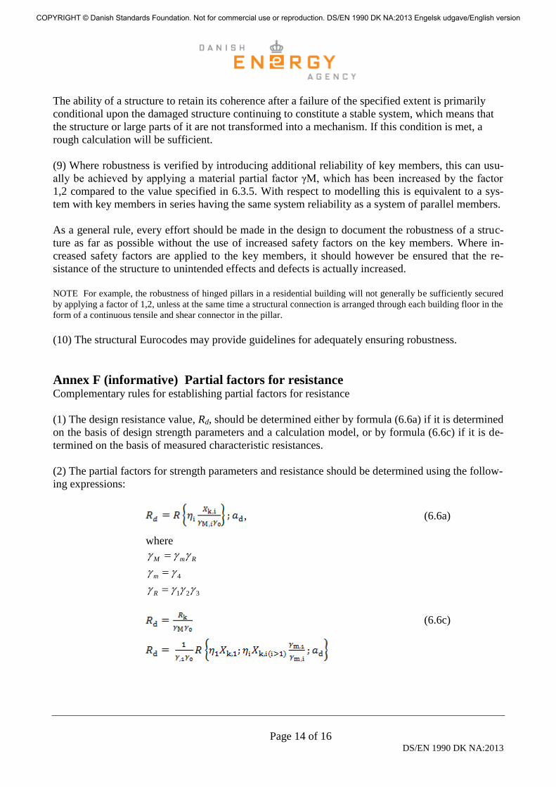
Annex F (informative) Partial factors for resistance Complementary rules for establishing partial factors for resistance
(1) The design resistance value, Rd, should be determined either by formula (6.6a) if it is determined
on the basis of design strength parameters and a calculation model, or by formula (6.6c) if it is de-
termined on the basis of measured characteristic resistances.
(2) The partial factors for strength parameters and resistance should be determined using the follow-
ing expressions:
, (6.6a)
where
RmM
4 m
321 R
(6.6c)
COPYRIGHT © Danish Standards Foundation. Not for commercial use or reproduction. DS/EN 1990 DK NA:2013 Engelsk udgave/English version
Page 15 of 16 DS/EN 1990 DK NA:2013
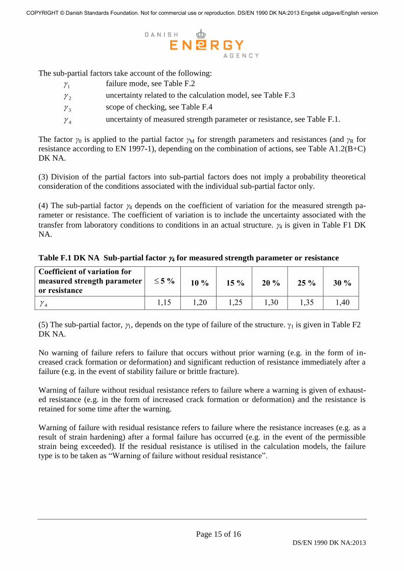
The sub-partial factors take account of the following:
1 failure mode, see Table F.2
2 uncertainty related to the calculation model, see Table F.3
3 scope of checking, see Table F.4
4 uncertainty of measured strength parameter or resistance, see Table F.1.
The factor γ0 is applied to the partial factor γM for strength parameters and resistances (and γR for
resistance according to EN 1997-1), depending on the combination of actions, see Table A1.2(B+C)
DK NA.
(3) Division of the partial factors into sub-partial factors does not imply a probability theoretical
consideration of the conditions associated with the individual sub-partial factor only.
(4) The sub-partial factor 4 depends on the coefficient of variation for the measured strength pa-
rameter or resistance. The coefficient of variation is to include the uncertainty associated with the
transfer from laboratory conditions to conditions in an actual structure. 4 is given in Table F1 DK
NA.
Table F.1 DK NA Sub-partial factor 4 for measured strength parameter or resistance
Coefficient of variation for
measured strength parameter
or resistance
5 % 10 % 15 % 20 % 25 % 30 %
4 1,15 1,20 1,25 1,30 1,35 1,40
(5) The sub-partial factor, 1, depends on the type of failure of the structure. 1 is given in Table F2
DK NA.
No warning of failure refers to failure that occurs without prior warning (e.g. in the form of in-
creased crack formation or deformation) and significant reduction of resistance immediately after a
failure (e.g. in the event of stability failure or brittle fracture).
Warning of failure without residual resistance refers to failure where a warning is given of exhaust-
ed resistance (e.g. in the form of increased crack formation or deformation) and the resistance is
retained for some time after the warning.
Warning of failure with residual resistance refers to failure where the resistance increases (e.g. as a
result of strain hardening) after a formal failure has occurred (e.g. in the event of the permissible
strain being exceeded). If the residual resistance is utilised in the calculation models, the failure
type is to be taken as “Warning of failure without residual resistance”.
COPYRIGHT © Danish Standards Foundation. Not for commercial use or reproduction. DS/EN 1990 DK NA:2013 Engelsk udgave/English version

Page 16 of 16 DS/EN 1990 DK NA:2013
Table F2 DK NA Sub-partial factor 1 depending on type of failure
Type of failure
Warning of
failure with
residual re-
sistance
Warning of
failure without
residual re-
sistance
No warning
1 0,90 1,00 1,10
(6) The sub-partial factor 2 depends on the coefficient of variation for the calculation model. The
coefficient of variation is established by comparing resistances determined by testing the structural
members and by applying the calculation model, with the use of measured/given strength parame-
ters and geometric dimensions. As an exception, the coefficient of variation may be determined as
an estimate. 2 is given in Table F3 DK NA.
Table F.3 DK NA Sub-partial factor 2 for uncertainty of the calculation model
Coefficient of variation of
the calculation model 5 % 10 % 15 % 20 % 25 %
2 1,05 1,10 1,15 1,20 1,25
(7) Sub-partial factor 3 depends on the level of checking in connection with the production of
components and execution at the construction site. Requirements for levels of checking may be giv-
en in EN 1992 to EN 1999 and in the Danish national annexes thereto. 3 is given in Table F4 DK
NA. The extended level of checking is used on the condition that third party checking is conducted.
Table F4 DK NA Sub-partial factor 3 dependent on the scope of checking in connection with
the production of components and execution at the construction site.
Level of checking Extended Normal Reduced
3 0,95 1,00 1,10
(8) In (2), 4 covers the variation of the strength parameter. By checking the strength parameter it
will be possible to evaluate both the characteristic value and the coefficient of variation, which may
differ from what was assumed when the partial factor was set, see EN 1992 to EN 1998.
(9) When examining accidental design situations or seismic design situations, the partial factor M =
1,0 is used unless otherwise stated in EN 1992, EN 1993, EN 1994, EN 1995, EN 1996, EN 1997,
EN 1998 or EN 1999.
COPYRIGHT © Danish Standards Foundation. Not for commercial use or reproduction. DS/EN 1990 DK NA:2013 Engelsk udgave/English version