drum sense final
TRANSCRIPT

DRUM SENSE SMART LED DRUM SET
Azra Skeljo
Advisor: John Oliver
Senior Project Electrical Engineering Department
California Polytechnic State University San Luis Obispo
2015

2
Table of Contents I. List of Tables………………………………………………………………………..3 II. List of Figures……………………………......……………………………………....3-4 III. Abstract…………………….………...………………………………………….…..5 IV. Chapter 1: Introduction.………………………………………………...…………...6 V. Drum Jargon……………………………………...…………………………………7 VI. Background……………………………..……………………………….....………...8 VII. Chapter 2: Requirements and Specifications..……… ……………………………….15 VIII. Chapter 3: Functional Decomposition (Level 0 and Level 1)……………….………..17 IX. Chapter 4: Project Planning (Gantt Chart and Cost Estimates)……………………....26
Appendices
A. Appendix A: Support Documents…….………………………………………………....29 B. Appendix B: References………………………………………………………………....32 C. Appendix C: Senior Project Analysis…………………………………………………….35

3
List of Tables and Figures Table
1. SMART LED drum set startup costs…………..……………………………………….10 2. Frequency range of various drums as shown in Figure 20…………………...…………...13 3. Advantages and disadvantages of my proposed piezoelectric sensors …….………….....13 4. BrightBeats company feature comparison [3]1 …………..……………………………...14 5. Engineering versus marketing requirements…………………………………………….15 6. Power design specifications…………..………………………………………………....16 7. Mobile design specifications…………..…………………………………………..…….16 8. Scalable design specifications…………..……………………………………………….16 9. Features design specifications…………..…………………………………………....….16 10. Cost design specifications…………..………………………………………………..….16 11. Drum Sense top level functionality………………………………..........................……....17 12. Microcontroller level 1 functionality……………………………….…………………....19 13. RGB LEDs level 1 functionality…………………………..…………………………….19 14. Testing and verification plan……………………………………...……………………..21 15. Highest piezo voltages recorded…………..…………………………………………….22 16. Schottky testing values…………..…………………………………………………...….23 17. The ratings of the electrical components…………..……………………………………25 18. All the components needed to create 1 LED Drum Set……….……….…………....…..26 19. Drum sense deliverables……………………………………………………….………..26 20. Estimated cost to prototype 1 floor tom drum…………..……………………………...28
Figure
1. Sample drum trigger………………………...………………………...……………...…..5 2. Various drumbeaters…….………………………..………………………...………..…..6 3. Drum clutch…………………………………………………………………….………6 4. Drum counterhoop……………………………………………………...………………6 5. Floor drums………………………...…………………………………………………...6 6. Drum lug………………………..………………………………………………………6 7. Toms………..……………..……………………………………………………………6 8. Drum spur………..……………………..………………………………………………6 9. “The Ludwig” ………..…………………………………………………………………7 10. Low-boy cymbal………..……………………………………..…………………………7 11. Drum pad kit………..………………………………………...…………………………7 12. Standard drum set………..………………………………………………....……………8 13. Brightbeats logo………..…………………………………………………...……………8 14. JerEd Systems logo………..…………………………………………..…………………9 15. Love Your Drums logo………..…………………………………………………………9
1 JerEd Systems and Love Your Drums produce drum triggers, which do not communicate with the strength of

4
16. Amazon logo………..…………………………………………………………......……11 17. Wholesale LEDs logo………..…………………………………………………………11 18. Mouser logo………..………………………………………………………………...…11 19. Protocase logo………..…………………………………………………………...…….11 20. Frequency spectrum of a drum set………..…………………………………………….12 21. Functionality of piezoelectric device………..…………………………………………...13 22. Level 0 black box diagram………..………………………………………………..……17 23. Level 1 black box diagram………..……………………………………………………..18 24. Conditioned versus unconditioned piezo capture………..…………………………...…20 25. Software flowchart………..……………………………………………………….……20 26. Initial piezo conditioning circuit………..……………………………….………………22 27. Final hardware circuit………..…………………………………………….……………23 28. Output of the peak detector circuit capture………..……………………………………24 29. MOSFET LED control circuit………..…………………………………....……………24 30. Interrupt service routine………..………………………………………….……………25 31. Proposed Gantt chart spanning the project’s 20 weeks………..…………...……………26
Equation
1. Initial voltage drop calculation……..…………………………………………………...23 2. Slew rate equation……..……………………………………………………………..…24

5
Abstract I would like to propose a SMART drum set (Figure 1): a 5-piece acrylic LED drum set with 2 strips of adhesive RGB LEDs under each rim of every drum. Current SMART drum sets are very expensive and come as installable light rings that are attached on the outside of the drum instead of the inside. I have successfully prototyped 1 Floor Tom of the complete set. The LEDs are connected an AC to DC power converter via a six pin MIDI connector and Arduino. The drum set is characterized with a single RGB microcontroller, 5 sets of 150 LEDs, a piezoelectric sensor, a six-pin MIDI connector, a 120V to 12V power converter, and an amplifying circuit. As a drummer hits each drum the piezoelectric sensor will trigger the LED light to spike in brightness depending on the strength of the hit and fade out over a period of time. The sensitivity of light will be controlled by a potentiometer. These optical illusions will enhance the overall drum set and provide onlookers with a visual performance. This system is a single prototype that can be expanded to a full drum set and is versatile in that it can work for any size drum or a larger drum set. Future work entails the design and manufacture of a control panel for the system to allow drummers to quickly change between settings during a performance. Lastly, a tutorial feature will be included for drum enthusiasts and new learners to promote visual, hands-on learning.
Figure 1: Sample drum trigger
6
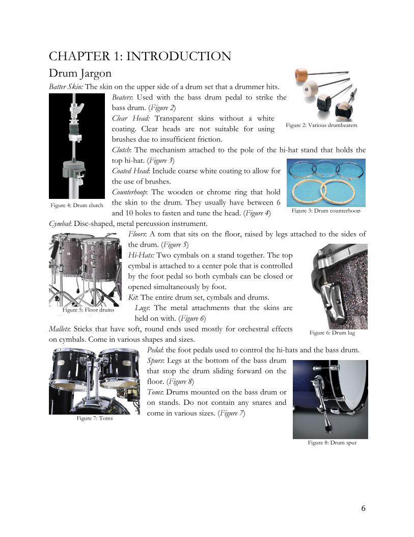
CHAPTER 1: INTRODUCTION Drum Jargon Batter Skin: The skin on the upper side of a drum set that a drummer hits.
Beaters: Used with the bass drum pedal to strike the bass drum. (Figure 2) Clear Head: Transparent skins without a white coating. Clear heads are not suitable for using brushes due to insufficient friction. Clutch: The mechanism attached to the pole of the hi-hat stand that holds the top hi-hat. (Figure 3) Coated Head: Include coarse white coating to allow for the use of brushes. Counterhoop: The wooden or chrome ring that hold the skin to the drum. They usually have between 6 and 10 holes to fasten and tune the head. (Figure 4)
Cymbal: Disc-shaped, metal percussion instrument. Floors: A tom that sits on the floor, raised by legs attached to the sides of the drum. (Figure 5) Hi-Hats: Two cymbals on a stand together. The top cymbal is attached to a center pole that is controlled by the foot pedal so both cymbals can be closed or opened simultaneously by foot. Kit: The entire drum set, cymbals and drums.
Lugs: The metal attachments that the skins are held on with. (Figure 6)
Mallets: Sticks that have soft, round ends used mostly for orchestral effects on cymbals. Come in various shapes and sizes.
Pedal: the foot pedals used to control the hi-hats and the bass drum. Spurs: Legs at the bottom of the bass drum that stop the drum sliding forward on the floor. (Figure 8) Toms: Drums mounted on the bass drum or on stands. Do not contain any snares and come in various sizes. (Figure 7)
Figure 2: Various drumbeaters
Figure 4: Drum clutch Figure 3: Drum counterhoop
Figure 5: Floor drums
Figure 6: Drum lug
Figure 7: Toms
Figure 8: Drum spur

7
Background
Today’s drum kit began to take shape around 1930 [2]. Many bands in the late 1800’s had multiple drummers where each drummer was assigned to a specific drum or set of drums. As stages began to shrink over time so did the drum kit. The invention of the spring driven pedal in 1909 by William F. Ludwig and his brother Theobald revolutionized drumming with a new mechanism that would allow for one drummer to play two drums at once. Further a spring was installed to allow for faster and less tiring play than the classic heel-toe striking and recoiling method used prior. “The Ludwig ‘Jazz-er-up’ outfit (Figure 9) consisted of a 24” X 8 bass drum, 12” X 3 snare drum,
bass drum pedal with cymbal striker, suspended cymbal and hoop mounted wood block [2].” The addition of low-boys (Figure 10), hi-hats, and tunable toms soon became exceedingly popular. In 1935, Gene Krupa changed the face of drumming by using a “Stripped Down Kit”, consisting of a standard four-piece drum kit, plus top and bottom tuneable toms. The increased popularity and technology of the snare drum was soon added to the set, which completed what many know
today as the modern drum kit. In addition, the 80’s electronic scene introduced drum pad kits (Figure 11)
that could be tuned with the other synthesized sounds. Certain styles of music then modified the classic kit by adding or removing certain drums to produce specific sounds.
Figure 9: The Ludwig (1918)
Figure 10: Low-boy cymbal
Figure 11: Drum pad kit

8
Overview Most LED drum sets do not respond to drumming but instead loop through predefined color settings. This decreases the value of the visual performance and can be inconsistence with the music. Interest in a responsive light method is high according to the various drum enthusiasts blogs and social media but many hobby enthusiasts have a hard time creating a circuit that performs well. I explored various signal conditioning circuits and light control settings to maximize the drummer’s ease and control over the system. Most drum sets are used during live performances therefore have direct access to AC power. The design provides easy build-up and teardown. The design consists of LED strips that are attached inside the drum and string through a MIDI Cable through the breath hole of the drum and out to the ATmega328p microprocessor on the Arduino Uno.
Market Analysis The SMART LED drum set need is quickly gaining interest with only one significant company in the market. With the growing trend for LED infused visual performances, the market is fresh and opportunities are high.
Definition of Market Region: The enhanced drum kit market, enhanced refers to kits that contain LEDs, is barely impacted. There is currently one company that has developed a SMART drum product, however, their design contains rings that are mounted onto the outside of a drum which creates a different effect than if the LEDs are mounted inside.
Notable SMART Drum Kit Industry Competitors: BrightBeats [3] is currently the only company that has made significant progress and shaped the SMART LED Drum Kit industry. Their system consists of light rings that are mounted on the outside of the each drum and a simple control system that allows the drummer to adjust the duration and brightness of
the LEDs. Their technology has been used in
Figure 12: Standard drum set
Figure 13: Brightbeats Logo

9
performances just as the Taylor Swift Red Tour and Rascal Flatts. [3]
JerEd Systems [4] markets their drum trigger sets. They have a variety of lighting options including internal and external mounting options and triggers. Their system is fairly basic considering it
can only produce red, green, blue, yellow, cyan, and white colors and the settings are locked in.
The drummer does not have control over the fading features, brightness, light length, or any desired variations of color.
Love Your Drums [5] manufactures the Tour Ready DMX512 box that is
equipped with the light interface board and fully
installable flexible RBG LED strips. The control box is a basic 8-channel box that includes a small remote control with hundreds of various preset light patterns. This system is more sophisticated than the JerEd Systems product with the light features but does not contain a trigger and therefore does not respond to live drumming.
Size of Market: The total market for percussion instruments in 2002 was 475.3 million dollars. Today, the exact amount is unknown but probably in the same 500 million dollar range. In 2002, 35,420 drum machines were sold, 10,500 electronic drums, and 207,275 drum kits according to The Music Trades magazine’s Annual Music Products Industry Census for 2002 [6]. Around 2010 drum sales were on an upward trend, but year on year sales dropped 3.2% in 2011 and 9% in 2012 respectively. [7] The median age of musical instrument purchasers in the United States is 37.1 years old and per capita Americans spend $21.12 per year on instruments. [7] The rise of LED applications however, has sparked a new interest in people young and old in providing a visual and audio performance. The current SMART drum set company, BrightBeats’s, system has been infused into many famous artists’ performances including Taylor Swift and Rascal Flatts [3].
Key Strengths to Leverage that our Competitors Cannot: The main competitor for this SMART LED Drum Set is BrightBeats. Their design is user-friendly and has an ease of installation however, is limited in its lighting due to the sole outer lighting option, a ring of LEDs that attaches to the outer ring of the drum. Drum Sense will be installed inside the drum therefore, transmitting more light throughout. Including memory functionality to the system in the future can allow for live drum playback and promote drum education; each drum will light up when it needs to be hit therefore, doubling as active learning software.
Figure 14: JerEd Systems Logo
Figure 15: Love Your Drums Logo

10
Window of Opportunity: The current market houses very few competitors therefore, a very ergonomic and user-friendly product would allow for a successful business. An opportune time would be before the holidays or before spring because of the amount of shows and concerts that take place in spring and summer. In-store distribution and easy online purchasing is a key component in successfully marketing the product since many drummers are older, “propensity to be online declines with age…[for example] a 35 year old is 5.5% less likely to be online than a 25 year old.” [7]
How big of an effort would it take to enter the market? The estimated cost of developing Drum Sense and entering the market are shown in Table 1 below. The bulk of the entrance cost comes from purchasing the electronics including the LEDs, microprocessor, and sensor circuitry. A significant amount of time would need to be allotted to social networking and advertising to attract buyers. The most crucial part of developing an LED applications company is customer service. There are a variety of blogs, social group pages, websites, live events, and music stores that are able to provide a means to advertising.
Table 1: SMART LED drum set startup costs
Purchase Cost [$] Assumptions & Reasoning
Retail Space 20-84/sq. ft./year Average rent/square feet/month in
SF [5]
Engineers 70,000 Assuming team of 2 with 70,000
annual salary per for 6 months [6]
Hiring Process 3,000 total
Includes phone interviews, current employee time spent, and travel
expenses, etc.
Prototype 200 Average estimated for electronic components for two prototypes
Testing 1,000 This value comes from 5 times the
parts cost of a prototype
Marketing & Demos 1,000
The amount of time allotted from pay for attending events and posting on
social network
Miscellaneous 2,000 Failed designs, reworks, scheduled
meetings, events, etc. Total 82,200 Assuming 6 months of retail space
The start-up cost would be steep; however, the average cost of a 5-kit system would range around $1,000. Potential employees include programmers for LED programming and website design; hardware engineers for microprocessor and embedded design; individuals with finance knowledge to manage spending versus return; and electrical technicians to troubleshoot broken systems and

11
provide technical support. A stable, knowledgeable team of five to fifteen people guarantees a great product. Sales are made directly off a website or in-store with most advertising completed through social networking and live performances therefore; all existing sales organization is capable of selling into this market.
Key Partners for success:
Amazon [7] is great for basic products such as breadboards, cables, and other miscellaneous parts that may be needed to complete the final product. They offer fast and reliable shipping and can also be a great seller of the finished product.
Wholesale LEDs [8] are a great LED provider; they have a wide range of LED strips available at both 10V and 12V and offer support with any of their products.
Mouser electronics [9] has a great online database for purchasing electrical components. They tend to run slightly cheaper than Digi-Key and offer various shipping methods. They would be a great partner for purchasing of passive components, microprocessor, and other miscellaneous parts.
Protocase [10] is a top custom enclosure provider of electronics. They include an in-house powdercoat finish, precision cutouts, custom silkscreen finish, and add hardware and accessories to all enclosure orders. They are a great resource for making the final product sleek and user-friendly.
Figure 16: Amazon Logo
Figure 17: Wholesale LEDs Logo
Figure 18: Mouser Electronics Logo
Figure 19: Protocase Logo

12
Product Description Limiting Factor of present solutions: Currently, drum enthusiasts have difficulty conditioning the piezoelectric sensor, which causes inconsistences in the light patterns and drum response. BrightBeats [3] has a well functioning system though they do not provide their system specifications and methodologies. Other drum triggers on the market are not able to communicate with the loudness of drum hits, therefore, creating just small flashes with no dynamics.
Nature of my proposed solution: I explored ways to harvest voltage from the vibrations of a drum hit using a piezoelectric device also known as a drum trigger. The strength of the hit determines the brightness of the LEDs and illuminates the drum via an electronic signal between 0 and 5 Volts. The more force applied to the drum hit, the higher the voltage read by the microprocessor, causing the drum to light up brighter. The sensitivity of the system is controlled through a potentiometer and
can be later integrated with a
user-friendly knob on the control panel. The various standard drum frequency ranges are shown in Figure 20 above [11]. Since drums vary in size, sound, and frequency the selected piezoelectric sensor must cover all appropriate ranges in order for the lights to trigger correctly. The advantages and disadvantages of a couple applicable piezoelectric sensors are listed in the Table 3 below and the
Figure 20: Frequency spectrum of a drum set

13
basic functionality of a piezoelectric device is shown in Figure 21. Tension and compression of the piezo generates voltages of opposite polarity, and in proportion to the applied force [11].
Table 2: Frequency range of various drums as shown in Figure 20
Low Frequency [Hz] High Frequency [Hz] Cymbals2 200 7.5k-10k
Snare 240 5k-6k Toms 120-240 5k
Kick Drum 60-80 4k
Table 3: Advantages and disadvantages of my proposed piezoelectric sensors
Advantages Disadvantages
LDT1-028K [9]
-Large output voltage 10mV-100V -Impedance controlled (~1MOhm+) -Special order specifications available
-Does not have distinct frequency range
-Must be mounted in a cantilever arrangement
SDT1-028K [10]
-Impedance controlled (~1MOhm+) -Output voltage 15-20MV/u strain
-Shielded, low noise -Wide frequency range
-Particular to adhesive and attaching method
Figure 21: Functionality of Piezoelectric Device
2 Cymbals will not include LEDs, this value is provided to show the variety of ranges in a complete drumset.

14
Competing Product Solutions:
Table 4: BrightBeats company feature comparison [3]3
BrightBeats
Price $1400 (complete set)4 Sizes All drum sizes
Warranty Yes, add-on service Availability Immediate
User Interface Full Color Touch Screen and knobs Power Up to 350 Watts of continuous output power
Save and Recall Mode Yes Adjustable Brightness Yes
Light Pattern Customizability High. Individual channel LED color mixing control
Mode Selection DMX integration to allow a light controller to take control of
some or all channels.
Compatibility High. Works in conjunction with electronic drum controllers such as Roland, 2Box, or Alesis by splitting trigger outputs
Foot Switch Yes, 2 Channel USB Port Yes, used for backup and restore of system settings
Customer Desired Attributes:
• Market price must not exceed competing solution options, <$1400 • LEDs must securely attach and detach to inside of the drum • Overall lightweight, scalable, and can be used for all drum sizes • Upgradeable for future software updates and advancements • No rattle design with drum force • LEDs shine all throughout the drum, no significant light gaps • Sensitivity and color control of all LEDs
3 JerEd Systems and Love Your Drums produce drum triggers, which do not communicate with the strength of drum hits, therefore, BrightBeats is the main competitor. 4 A complete set includes a light set for a bass drum, snare drum, and two floor toms.

15
CHAPTER 2: REQUIREMENTS & SPECIFICATIONS Table 5 below lists the engineering requirements and specifications for this project as classified by its marketing requirements.
Table 5: Engineering versus marketing requirements
Marketing Requirements
Engineering Requirements Justification
5, 6, 7 The piezoelectric sensor must be able to process the full span of drum frequencies ~60Hz-
7kHz
Based off competitor-powered devices, this power output should be obtainable.
2, 5, 7 The output voltage to the LEDs needs to be 12 volts.
This power output should be sufficient to meet the battery life requirements above.
1, 3, 4, 5 The learning curve should be less than 1 hour
Creating a user-friendly product will be more marketable and also simple to troubleshoot
1, 2, 4, 5, 6 Market price must not exceed $1400
Beyond this price, Hoopers have the option of buying competitor hoops. This keeps the hoop very marketable to most Hoopers. Below this
price will decrease system quality and durability.
2, 3, 5, 7 A dial (potentiometer) will control the brightness of the
system via a control box
Light gap in the tubing is one of the largest turn-offs to Hoopers therefore having a large
gap with decrease marketability.
Marketing Requirements: 1. The drum system should be easily installed and disassembled for travel. 2. The drum system should have excellent color and brightness. 3. The drum system should be easy to use and have a minimal learning curve. 4. The drum system shall be affordable <$1400 for the targeted drummer. 5. The drum system shall be user configurable from a centralized control box. 6. The drum system shall be customizable to meet all drum sizes. 7. The drum system shall have a warranty on all electronic components.
All major design specifications for Drum Sense are listed in the Tables 6-10 below.

16
Power specifications Table 6: Power design specifications
Engineering Specifications Reasoning a
The piezoelectric sensor must be able to process the full span of drum frequencies ~60Hz – 7kHz.
All drums should be read through signal system without tampering of the controller code.
b The output voltage to the LEDs needs to convert from the wall and deliver 12 volts.
This output voltage should be sufficient to meet the needs of all three colors of LEDs.
c The microprocessor voltage must not exceed 5 volts.
Keep the circuit safe and stay within max ratings.
Mobile
Table 7: Mobility design specifications
Engineering Specifications Reasoning a The system shall be customizable to meet all
drum sizes. Must be flexible for all drum sets and preferences.
b The system must be rugged and easily taken apart and setup for travelling musicians.
Must be durable and withstand quick packing and setups.
c The system should weigh no more than 25 lbs. Allows for easy travel and carry. Scalable
Table 8: Scalability specifications
Engineering Specifications Reasoning a
Additional lights and parts can be easily incorporated to the original system.
Allows for flexibility in purchase and reduces pressure on drummer to buy set for drums not always in use.
Features
Table 9: Key features
Engineering Specifications Reasoning a The system should have excellent color and
brightness. Must be well seen from the back of a large musical venue.
b A dial (potentiometer) will control the brightness of the system via a control box.
Allows the drummer to control the lights based on the song’s feel and loudest.
Cost
Table 10: Cost specifications
Engineering Specifications Reasoning a The system shall be affordable <$1400
for a typical 6-piece drum set. Offering a competitive price with durable electronics will allow us to compete in the marketplace.

17
CHAPTER 3: FUNCTIONAL DECOMPOSITION (LEVEL 0 & LEVEL 1) Block Diagram & Requirements
Figure 22: Level 0 Black Box Diagram
Figure 22 shows an overview of the system with its main inputs and outputs. This provides a top-level understanding of how the system will be implemented. The main requirements for the system to work under the provided specifications are the power, sensor, and sensitivity control. These three inputs will create the LED light output.
Table 11: Drum Sense top-level functionality
Input/Output Type Description Input Power Main input supply power: 120V AC converted to 12V DC Input Sensitivity control Allow user to adjust the brightness and duration of lit LEDs Input Piezoelectric
transducer Translates the strength of a drum hit into a voltage
Output LEDs LEDs are lit up by the microcontroller in combination with the strength of the drumming and sensitivity control

18
Figure 23: Level 1 Black Box Diagram
Figure 23 displays the next level of understanding following Figure 22; it shows how all the pieces of
the project are interconnected. Notice the main subsections of the system: power, analog, and digital. The analog portion consists of the hardware in the conditioning circuit Figure 27; the digital portion comprises of the Arduino and its functionalities; and the power is composed an AC to DC
converter.
19
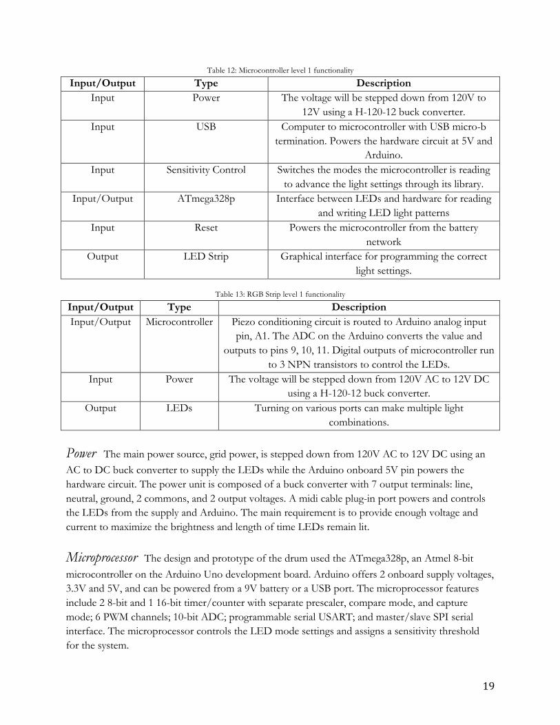
Table 12: Microcontroller level 1 functionality
Input/Output Type Description Input Power The voltage will be stepped down from 120V to
12V using a H-120-12 buck converter. Input USB Computer to microcontroller with USB micro-b
termination. Powers the hardware circuit at 5V and Arduino.
Input Sensitivity Control Switches the modes the microcontroller is reading to advance the light settings through its library.
Input/Output ATmega328p Interface between LEDs and hardware for reading and writing LED light patterns
Input Reset Powers the microcontroller from the battery network
Output LED Strip Graphical interface for programming the correct light settings.
Table 13: RGB Strip level 1 functionality
Input/Output Type Description Input/Output Microcontroller Piezo conditioning circuit is routed to Arduino analog input
pin, A1. The ADC on the Arduino converts the value and outputs to pins 9, 10, 11. Digital outputs of microcontroller run
to 3 NPN transistors to control the LEDs. Input Power The voltage will be stepped down from 120V AC to 12V DC
using a H-120-12 buck converter. Output LEDs Turning on various ports can make multiple light
combinations.
Power The main power source, grid power, is stepped down from 120V AC to 12V DC using an AC to DC buck converter to supply the LEDs while the Arduino onboard 5V pin powers the hardware circuit. The power unit is composed of a buck converter with 7 output terminals: line, neutral, ground, 2 commons, and 2 output voltages. A midi cable plug-in port powers and controls the LEDs from the supply and Arduino. The main requirement is to provide enough voltage and current to maximize the brightness and length of time LEDs remain lit.
Microprocessor The design and prototype of the drum used the ATmega328p, an Atmel 8-bit microcontroller on the Arduino Uno development board. Arduino offers 2 onboard supply voltages, 3.3V and 5V, and can be powered from a 9V battery or a USB port. The microprocessor features include 2 8-bit and 1 16-bit timer/counter with separate prescaler, compare mode, and capture mode; 6 PWM channels; 10-bit ADC; programmable serial USART; and master/slave SPI serial interface. The microprocessor controls the LED mode settings and assigns a sensitivity threshold for the system.

20
LEDs The 2034 SMD Color Changing RGB LED Strip has an input voltage of 12V DC and an overall power rating of 36W per 16.4 feet. They have adhesive on the back therefore, stick well inside the drum and are further secured with clear packaging tape.
Hardware Piezoelectric transducers are very common, however; their signal is not conditioned for digital use: it is roughly a sine wave that dampens over time. The signal, in this case, always has a negative peak close to or of equal value to its positive peak. This is a huge issue for most digital chips. I used passive components to extract and filter the peak value from the piezoelectric signal. The piezoelectric transducer is conditioned through the circuit seen in Figure 27. In Figure 24, the green signal is the unconditioned piezo whereas; the yellow is the signal after the conditioning circuit. Notice the amount of negative signal produced by the piezo (green) and how it is completed attenuated after running through the piezo conditioning circuit (Figure 27). The circuit attenuates the negative signal and decays over time to produce an easily detectable signal (Figure 24).
Software Code is implemented to control the light output on the LEDs. After a few short initialization sequences to set the parameters for the ADC, timer, and the various ports, the code is set to interrupt when a peak is detected or a threshold is breached. If the peak is detected, the LEDs are programmed with a desired color combination. Once the LEDs are turned on, a reset pin—connected to a transistor—is turned on to provide a current path to ground and turn off the LEDs. If a peak is not detected, the loop continues until the threshold set is exceeded. Refer to Figure 25 below for the flowchart of the key code requirements.
Figure 24: Conditioned versus unconditioned piezo signal
Figure 25: Software flow chart

21
Testing & Verification Table 14: Testing and verification plan
Engineering Specifications
Testing Protocol Results Pass/Fail
1
The piezoelectric sensor must be able to process the full span of drum frequencies ~60Hz –
7kHz.
Test the sensor on all drum sizes in various locations on the bottom head to find the
best signal response.
Placement of the sensor in the middle of the bottom drumhead produces the cleanest peak and misses
peaks least frequently.
✓
2 The system shall be
customizable to meet all drum sizes.
The components need to be rated for the high and lowest frequencies and withstand all
currents.
All components are rated well and have a tolerance to
withstand the largest and smallest drums.
✓
3
Additional lights and parts can be easily
incorporated to the original system.
Enough ports available to connect standard 6-piece drum set with the system
linked together.
If the system is for a drum set larger than 6 pieces and each drum is individually
controlled then the Arduino Uno will not suffice.
✗
4
A dial (potentiometer) will control the
brightness of the system via a control box.
By turning the potentiometer, the ADC
outputs various values and increases or decreases the sensitivity of the peak read
in.
The potentiometer is turned during drumming to see
how the brightness of the light is affected.
✓
5 The system shall be
affordable <$1400 for a typical 6-piece drum set.
Buy reasonably priced and scalable parts.
All electrical parts were ~$5.00 and under, while
converters and other equipment was under
~$30.00
✓
The projected testing and verification plan of the engineering requirements and specifications are shown using the following methods in Table 14 above.
Specifications & Design Decisions Figure 27 below shows the schematic of the piezoelectric signal conditioning circuit; Table 17 lists all components and electrical specifications of all necessary parts; and Table 18 lists the necessary parts to equip a single drum with the technology. I was given many parts from Philip Tyler’s previous drum project therefore; some design decisions were already completed for me in this case. The power unit, LEDs, MIDI Cable port, drum, Arduino, passive components, and wires were given to me at the start of the project.

22
Power The power converter (H-120-12) was a previous purchase of Philip’s and works well in supplying the system with ample power. In order to minimize power conversions through the project, I utilized the 5V onboard voltage the Arduino has to power both operational amplifiers seen in the circuit in Figure 27. Though the Arduino is currently powered through the USB computer port, it can be easily removed and powered through a 9V battery or via a voltage regulator to step down the 12V DC power from the output of the converter.
Piezoelectric Transducer Conditioning the piezoelectric sensor was the original objective of the project. The issue with piezoelectric sensors is stated in the hardware section above on page ___. Choosing a piezo was easy because only two could produce a high voltage. The difference between the two was packaging, either a shielded or laminated casing. I chose the laminating casing because it would be easier to implement and keep secure compared to a shielded. The highest voltage ratings outputted from a bare piezo are shown below in Table 15.
Table 15: Highest piezo voltages recorded
Voltage [V] Vpk-pk 116 Vmin -80.4 Vmax 35.4
Figure 26: First iteration piezoelectric sensor signal conditioning circuit

23
Figure 27: Final hardware circuit
Hardware 1. Piezo-conditioning circuit The main portion of the conditioning circuit goes to part D3. D1
was picked from a collection of diode parts given to me by Philip Tyler based on its forward voltage. Originally I tested part 1N4001 that has a VRRM of 50V, it produced lower minimums and maximum voltage values out of the piezo as seen in Table 16. Therefore, using 1N4004 produced higher positive voltage and cut out more negative voltages; an overall better option. The zener diode, D3 was chosen for its reverse breakdown voltage of 5.1V, the high rail of the circuit. By adding D3, it guarantees the signal will not exceed the zener’s breakdown voltage. The value for R1 was calculated using Equation 1 below. Figure 26 shows the first iteration of the conditioning circuit, this circuit did not provide the best possible output and many portions were unnecessary. Therefore, they were removed to decrease costs and increase system efficiency. Also, the first iteration did not provide a long enough decay for the piezo peak to be reliably detected by the Arduino; a peak detection circuit was added to improve this problem.
Table 16: Schottky testing values
1N4001 [V] 1N4004 [V] Minimum Voltage -4.8 -4.0 Maximum Voltage 10.5 11.3
Peak Voltage 15 15.3
Equation 1: Voltage drop equation
𝑡 90% = 2.2𝑅𝐶
2. Op-amp circuit The operational amplifiers are the same for both U1 and U3; they were selected from the parts IEEE carries in their parts bank. I chose a single source, rail-to-rail op-amp in order to receive maximum output of each stage; otherwise the op-amp would output only half the supply from the first stage after accounting for necessary headroom. The single supply op-amp I chose could run off the Arduino onboard voltage of 5V, is a dual package, has an output current of 13mA, and a slew rate of 1.1V/us. Slew rate

24
determines how quickly the output can change in a period of time. This is critically in being able to pick up the peak outputted by the piezo. At max drum frequency (snare drum at 10kHz) and max unconditioned piezo voltages, the required slew rate would be at approximately 6.3V/us but after conditioning for a floor tom, max frequency 5kHz, a slew rate around 0.1V/us will suffice. Slew rate is determined using Equation 2 below. The
Equation 2: Slew Rate
𝑆𝑙𝑒𝑤 𝑅𝑎𝑡𝑒 = 2𝜋 × 𝑓 × 𝑉
3. Peak detection circuit The role of the peak detection circuit is to monitor the voltage and retain its peak value at its output. The input signal charges the hold capacitor, and the diode presents the capacitor from discharging. The second op-amp, U3 carries the held voltage to the output via the driver op-amp. If the input voltage increases, the peak will increase, however if it decreases the peak value on the output will stay the same (Figure 28). The figure shows the decay of the piezo, a key concept of the project, since the Arduino must reliably detect all drum hits. The values are chosen based on the RC time constant, I chose a value of 0.1s because it provides enough peak information for the ADC.
4. Reset circuit The reset circuit provides a current path to ground to reset the peak detector
capacitor, C2. I chose an NPN with a low collector-emitter saturation voltage in order to turn the quickly saturation and pull the current to ground. The MJE3055T has a VCE(sat) equal to 1.1V which is easily exceeded with an average drum hit. This part was chosen based on the parts available at the Radio Shack in town.
5. LED control circuit The LED
control circuit can be seen in Figure 29, it provides a current path to ground to switch the LEDs on and off. I used the same transistors in the hardware for consistency and because they worked in both applications.
Figure 28: Output of the peak detector circuit
Figure 29: MOSFETs to control LEDs

25
Software The interrupts are asserted at 8kHz, a number determined by Philip based on how quickly he can play his drums (Figure 30). The figure displays the interrupt occurring every 125us, proving the timer and interrupts work. The ADC, however, did not work in asserting values from 0
to 1023 due to unknown circuitry issues, therefore; the ADC assigns a value of 991 (low) or 1023 (high). These modified values are used as a high and low designation with the threshold assigned at 1000. Therefore, when the piezoelectric sensor is sensed as hit the analog pin is set high and the drum is turned on. The code is designated to turn on all 3 ports: red, blue, green, respectively causing the lights to drum to shine red, purple, white 3 times through because the NPN pulls the current to ground. Code can be found in Appendix A.
Table 17: The ratings of the electrical components
Component Part Number Voltage Rating Current Rating [A] Power [W] Piezo Sensor (C1) LDT1-028K 10mV-100V -- --
D1, D2 1N4004 VRRM= 400V Io= 1 -- D3 1N4733A 5.1V IR= 10u at 1V 1.3
R1-R6 1% Metal Film -- -- 1/4 C2 Ceramic 50V -- --
Q1-Q4 MJE3055T VBE= 5V VCE= 60V
IB= 6 IC=10
75
U1, U3 LMC662CN 15V Output pin = 18mA Temperature dependent
U2 R100k -- -- --
Figure 30: Interrupt service routine

26
Table 18: Components needed to light 1 drum
Project Parts 1 piezoelectric transducer [12] 1 R100k potentiometer 2 x 150 RGB LED Strip Passive components 1 Arduino Uno with ATmega328p microcontroller* [14] 1 AC to DC converter* 1 1N4733A Zener diode [15] Connecting wires 2 1N4004 Schottky diodes [16] 4 MJE3055T NPN transistors [17] 2 LMC662CN Rail-to-Rail Gain Operational Amplifier [18] 1 MIDI Cable and connector *Can be applied to multiple drums. Majority of the components’ datasheets can be found in Appendix B.
CHAPTER 4: PROJECT PLANNING Project Schedule Table 19 below showcases the deliverables for this project. These are the major project deadlines included in the Gantt chart in Figure 31 below.
Table 19: Drum Sense deliverables
Delivery Date Delivery Description 1.12.2015 1st proposal draft 2.16.2015 Design review
1.2015-6.2015 Weekly design meetings 5.31.2015 Senior Project Expo: Demo 6.8.2015 Final proposal
Figure 31 below showcases the Gantt chart planned for the 20 original weeks. The plan changed over time and overall comprised of the hardware being completed Winter 2015 and software Spring 2015.
Figure 31: Initial proposed Gantt chart spanning the project’s 20 weeks

27
Most milestones listed above are small, achievable goals with quick deadlines. All integration portions were implemented and troubleshot towards the end of the project. High-risk items include programming and troubleshooting.
Cost & Resources Philip Tyler, the drummer of Louder Space, will finance the majority of this project however; I did apply for the monetary senior project grant from the EE Department to aid the cost. The estimated costs for the project are outlined below in Table 20.

28
Table 20: Estimated cost to prototype 1 floor tom drum
Item Cost 1 Piezoelectric transducer $5.00 1 AC to DC converter** $15.00
1 Arduino Uno with ATmega328p microcontroller $25.00 150 RGB LED strip (16.4 ft/reel) $17.99
Passive components $10.00 1 MIDI cable connectors** $2.00
Spool of 18-gauge solid copper class 2 power-limited circuit cable** $17.67 1 amplifier $2.00
1 breadboard $10.00 1 Potentiometer $2.00 Connecting wires $2.00
Total $108.66 ** Only need as many components as specified in chart for the whole system.
Resources Power Electronics Lecture Notes by Taufik Professors: Taufik, Oliver Louder Space drummer: Philip Tyler Tutor: Daniel Soski CPE 329 notes and material for programming Company websites: Digikey, Mouser, Amazon, Arduino, IEEE parts bank, etc.
Skills The skills I have acquired throughout this project include programming, design work, embedded systems, and sensor implementation.
Future goals This project has the potential to expand and be integrated into any type of drum set. Some future goals include adding memory and playback light modes, adding touch sensitive pads to control settings, and programming a complete light pattern bank.
29
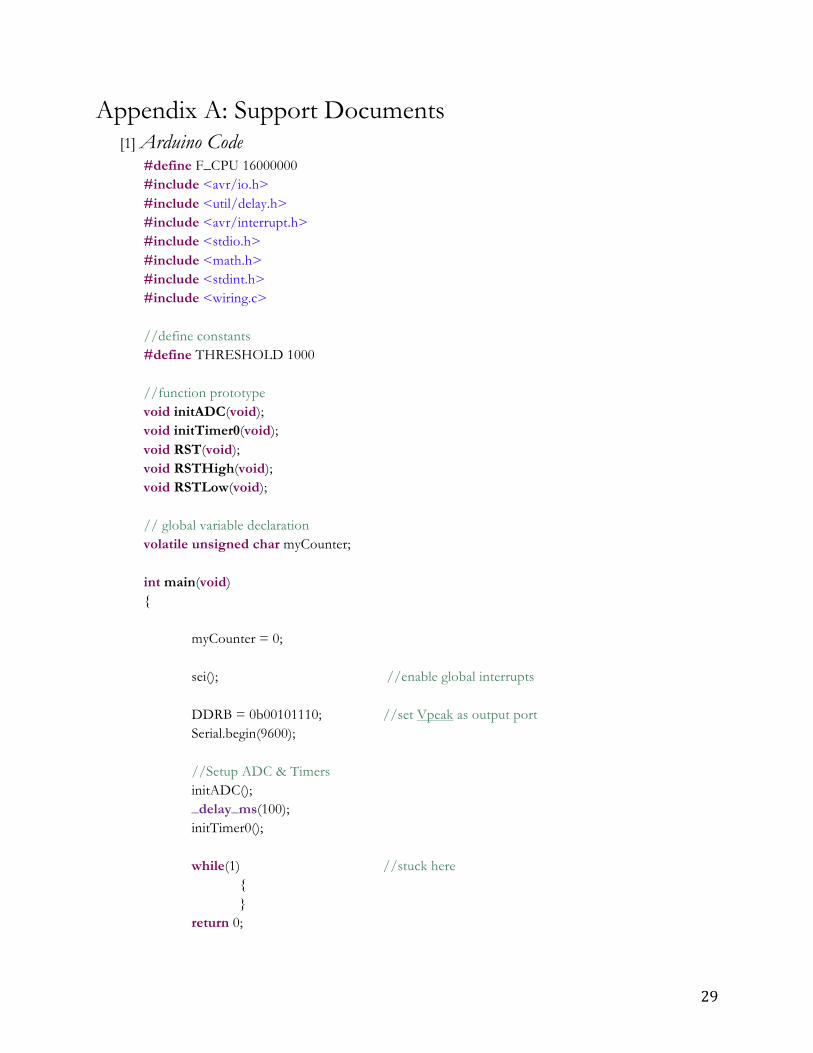
Appendix A: Support Documents [1] Arduino Code
#define F_CPU 16000000 #include <avr/io.h> #include <util/delay.h> #include <avr/interrupt.h> #include <stdio.h> #include <math.h> #include <stdint.h> #include <wiring.c> //define constants #define THRESHOLD 1000 //function prototype void initADC(void); void initTimer0(void); void RST(void); void RSTHigh(void); void RSTLow(void); // global variable declaration volatile unsigned char myCounter; int main(void) { myCounter = 0; sei(); //enable global interrupts DDRB = 0b00101110; //set Vpeak as output port Serial.begin(9600); //Setup ADC & Timers initADC(); _delay_ms(100); initTimer0(); while(1) //stuck here { } return 0;

30
} // end main void initADC(void) { ADMUX = 0x01; //set ADC channel ADC1 with 1X gain ADCSRA = 0x80; //turn on ADC and set prescaler (clk /8) //MAX A/D conversion rate 5 kHz @ 2 MHz frequency //No auto-trigger ADCSRB = 0x00; //set gain and turn off auto-trigger DIDR0 = 0x00; //digital input buffer enabled } void initTimer0(void) { TCCR0A = 0x02; // CTC Mode TCCR0B = 0x02; // timer clk = system clk /8 TIFR0 = 0x02; // output compare A match flag TIMSK0 = 0x02; // compare match A interrupt enabled OCR0A = 250; // compare value }
ISR(TIMER0_COMPA_vect) { ADCSRA |= 0x40; // Sample at 8kHz while(ADCSRA & (1 << ADSC)); uint16_t adcValue = ADC;
if(adcValue > THRESHOLD) { RSTHigh(); PORTB |= 0b00101000; _delay_ms(100); PORTB |= 0b00100100; _delay_ms(100); PORTB |= 0b00100010; _delay_ms(100); PORTB &= 0b11010001; RSTLow(); }else{ PORTB &= 0b11010001; } Serial.println(adcValue); } void RSTHigh(void)

31
{ PORTB |= 0b00000001; } void RSTLow(void) { PORTB &= 0b11111110; }

32
Appendix B: References [1] "Drum Terminology." Drum Terminology. Enable Drums, n.d. Web. 20 Dec. 2014.
<http://www.enabledrums.com/drumterminology.htm>. Drum jargon useful in understanding the layout of a modern drum kit and its components.
[2] Deegan, Ray. "The Evolution of the Modern Drum Kit." DrumTek The Drummer's Headquarters. DrumTek, n.d. Web. 20 Dec. 2014. <http%3A%2F%2Fwww.drumtek.com.au%2Fhistory%2F22-the-evolution- of-the- modern-drum-kit.html>.
A blog post essentially featuring a detailed description of the history behind the modern
drum kit drummers use today. The article features a descriptive background on each component of the kit as it changed throughout history with the discovery of new technology.
[3] BrightBeats. N.p., n.d. Web. 21 Dec. 2014. <http://www.usabrightbeats.com/>.
BrightBeats is the leading SMART LED Drum Kit company at the moment. Their website was helpful in deciding what requirements I would like to meet with my LED drum system and what design constraints and trade-offs they utilized in their renowned technology.
[4] Ulmer, Jeremy, and Ed Skinner. "JerEd Systems." JerEd Systems. JerEd Systems, n.d. Web.
22 Dec. 2014. <http://www.jeredsystems.com/> JerEd Systems created the first Midi driven LED lighting device for musicians on the
market. Their system provides a good reference on current products on the market.

33
[5] Love Your Drums. Stauffer Custom Drums and Percussion, n.d. Web. 21 Dec. 2014. <http%3A%2F%2Floveyourdrums.com%2F>. Used as reference of current LED drum products on the market. [6] "Number of Drumsets Sold in the US in a Year." Google Answers. Google, 23 Apr. 2003. Web. 22 Dec. 2014. <http%3A%2F%2Fanswers.google.com%2Fanswers%2Fthreadview%3Fid %3D195887>. Google Answers forum question sited from The Music Trades magazine’s annual music products industry census for 2002. Provides the total value of sales for percussion instruments and an approximate statistic on the amount of drums sold in 2002. Useful market data for the development of a SMART LED Drum set. [7] "Flexible Color Changing RGB Ribbon Flexible LED Light Strip 12v (5m 16.4ft/reel) By
Ledwholesalers, 2034rgb." Amazon.com. Amazon, n.d. Web. 08 Feb. 2015. The LEDs used in the design, the website contains the specifications of the light strips and videos of possible implementations. [8] "Wholesale LEDs, RGB Strip Lights, Spotlights, Signs." Wholesale LEDs, RGB Strip Lights,
Spotlights, Signs. N.p., n.d. Web. 12 June 2015. [9] "Mouser Electronics." Mouser Electronics: Electronic Components Distributor. N.p., n.d. Web. 12 June
2015. [10] "HOW TO WORK WITH US." Custom Electronic Enclosures for Engineers and Designers. Protocase, 1999. Web. 22 Dec. 2014. <http://www.protocase.com/>. A great partner in creating an ergonomic and sleek design where users can control the brightness, duration, and sensitivity of their drum set. [11] "An Introduction to EQ." Music Technology Student. Digital Student: Music Tech Resources, n.d.
Web. 12 June 2015. [12] Specialties, Measurement. LDT1-028K Piezo Sensor W/ Lead Attachment. N.p.: Mouser, 12 May
2009. PDF. Datasheet for the piezoelectric sensor.

34
[13] Specialties, Measurement. SDT Shielded Piezo Sensors. N.p.: Mouser, 12 May 2009. PDF. Datasheet for a possible piezoelectric sensor. [14] "Atmel 8-BIT Microcontroller with 4/8/16/32KBytes In-System Programmable Flash." (n.d.):
1-641. Atmel Corporation. Atmel Corporation. Web. 1 Feb. 2015. Datasheet for ATmega328p microprocessor found on the Arduino Uno. [15] "Zener Diodes 1N4728A to 1N4764A." Vishay Electronics (n.d.): n. pag. Vishay. Vishay. Web. 21
Jan. 2015.
Datasheet for zener diode.
[16] Vester, Joachim. "Diode 1N4001 to 1N4007." Simulation Elektronischer Schaltungen Mit MICRO-CAP (2010): 68-113. Diodes Incorporated. Diodes Incorporated. Web. 21 Jan. 2015.
Datasheet for Schottky diode. [17]"Complementary-MOS Low-power, Low-voltage Integrated Binary Counter." STMicroelectronics
Reliability 9.4 (1970): 321. Utah State University. Web. 17 Mar. 2015. Datasheet for NPN transistors. [18] LMC662 CMOS Dual Operational Amplifier. N.p.: Texas Instruments, Apr. 1998. .pdf. Datasheet for both op-amps.
35
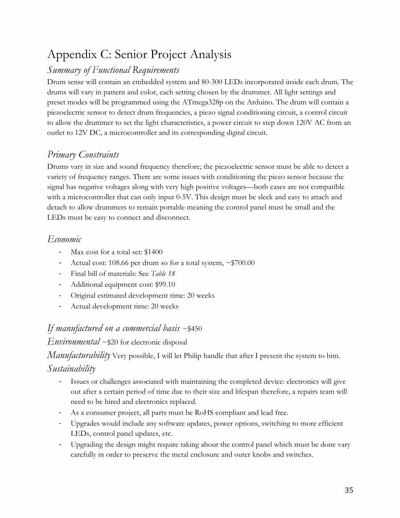
Appendix C: Senior Project Analysis Summary of Functional Requirements Drum sense will contain an embedded system and 80-300 LEDs incorporated inside each drum. The drums will vary in pattern and color, each setting chosen by the drummer. All light settings and preset modes will be programmed using the ATmega328p on the Arduino. The drum will contain a piezoelectric sensor to detect drum frequencies, a piezo signal conditioning circuit, a control circuit to allow the drummer to set the light characteristics, a power circuit to step down 120V AC from an outlet to 12V DC, a microcontroller and its corresponding digital circuit.
Primary Constraints Drums vary in size and sound frequency therefore; the piezoelectric sensor must be able to detect a variety of frequency ranges. There are some issues with conditioning the piezo sensor because the signal has negative voltages along with very high positive voltages—both cases are not compatible with a microcontroller that can only input 0-5V. This design must be sleek and easy to attach and detach to allow drummers to remain portable meaning the control panel must be small and the LEDs must be easy to connect and disconnect.
Economic -‐ Max cost for a total set: $1400 -‐ Actual cost: 108.66 per drum so for a total system, ~$700.00 -‐ Final bill of materials: See Table 18 -‐ Additional equipment cost: $99.10 -‐ Original estimated development time: 20 weeks -‐ Actual development time: 20 weeks
If manufactured on a commercial basis ~$450
Environmental ~$20 for electronic disposal
Manufacturability Very possible, I will let Philip handle that after I present the system to him.
Sustainability
-‐ Issues or challenges associated with maintaining the completed device: electronics will give out after a certain period of time due to their size and lifespan therefore, a repairs team will need to be hired and electronics replaced.
-‐ As a consumer project, all parts must be RoHS compliant and lead free. -‐ Upgrades would include any software updates, power options, switching to more efficient
LEDs, control panel updates, etc. -‐ Upgrading the design might require taking about the control panel which must be done vary
carefully in order to preserve the metal enclosure and outer knobs and switches.
36
Ethical -‐ Ethical implications: Since this is an electronic system, it is crucial the circuit be safe and
protected to prevent short circuits or other environmental factors from affecting its functionality. The system should be fairly damage proof to support a band lifestyle.
Health and Safety -‐ The final circuit will need to have short-circuit protection with high rated components to
prevent the drummer from electric shock or injury from the electrical components. All components must be RoHS compliant and lead free for the safety of the drummer as well.
Social and Political -‐ Social and political concerns associated with design, manufacture or use: All marketing must
be done on a fair and ethical basis. It is important that no other companies’ ideas, circuitry, or methods are used without their consent.
Development -‐ Describe any new tools or techniques, used for either development or analysis that you
learned independently during the course of your project: o An comfortable level of programming o Software and hardware integration o Advanced analog and digital design o Signal conditioning o Control circuitry o Ergonomic design methods o Patience o Troubleshooting techniques o Advanced level of oscilloscope usage o Formal proposal writing