drum: analog modeling drums lfo: low frequency … · • square with duty cycle control ... drum:...
TRANSCRIPT
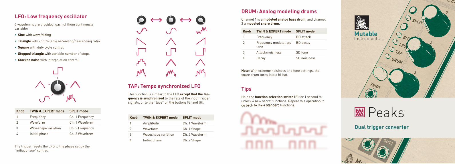
LFO: Low frequency oscillator5 waveforms are provided, each of them continously variable:
• Sine with wavefolding
• Triangle with controllable ascending/descending ratio
• Square with duty cycle control
• Stepped triangle with variable number of steps
• Clocked noise with interpolation control
Knob TWIN & EXPERT mode SPLIT mode
1 Frequency Ch. 1 Frequency
2 Waveform Ch. 1 Waveform
3 Waveshape variation Ch. 2 Frequency
4 Initial phase Ch. 2 Waveform
The trigger resets the LFO to the phase set by the“initial phase” control.
PeaksDual trigger converter
TAP: Tempo synchronized LFOThis function is similar to the LFO except that the fre-quency is synchronized to the rate of the input trigger signals, or to the “taps” on the buttons (G) and (H).
Knob TWIN & EXPERT mode SPLIT mode
1 Amplitude Ch. 1 Waveform
2 Waveform Ch. 1 Shape
3 Waveshape variation Ch. 2 Waveform
4 Initial phase Ch. 2 Shape
DRUM: Analog modeling drumsChannel 1 is a modeled analog bass drum, and channel 2 a modeled snare drum.
Knob TWIN & EXPERT mode SPLIT mode
1 Frequency BD attack
2 Frequency modulation/tone
BD decay
3 Attack/noisiness SD tone
4 Decay SD noisiness
Note: With extreme noisiness and tone settings, the snare drum turns into a hi-hat.
TipsHold the function selection switch (F) for 1 second to unlock 4 new secret functions. Repeat this operation to go back to the 4 standard functions.go back to the 4 standard functions.go back to the 4 standard functions.go back to the 4 standard functions.go back to the 4 standard functions.go back to the 4 standard functions.go back to the 4 standard functions.go back to the 4 standard functions.go back to the 4 standard functions.go back to the 4 standard functions.go back to the 4 standard functions.go back to the 4 standard functions.go back to the 4 standard functions.go back to the 4 standard functions.
About PeaksPeaks is a 2-channel multi-function signal generator: envelopes, synchronized low-frequency oscillations, or drum signals can be generated in response to triggers.
InstallationPeaks requires a -12V / +12V power supply (2x5 pins connector). The red stripe of the ribbon cable (-12V side) must be oriented on the same side as the “Red stripe” marking on the board.
The power consumption is as follows: -12V: 2mA ; +12V: 60mA.
Online manual and helpThe manual can be found online at mutable-instruments.net/modules/peaks/manual
For help and discussions, head to mutable-instruments.net/forum
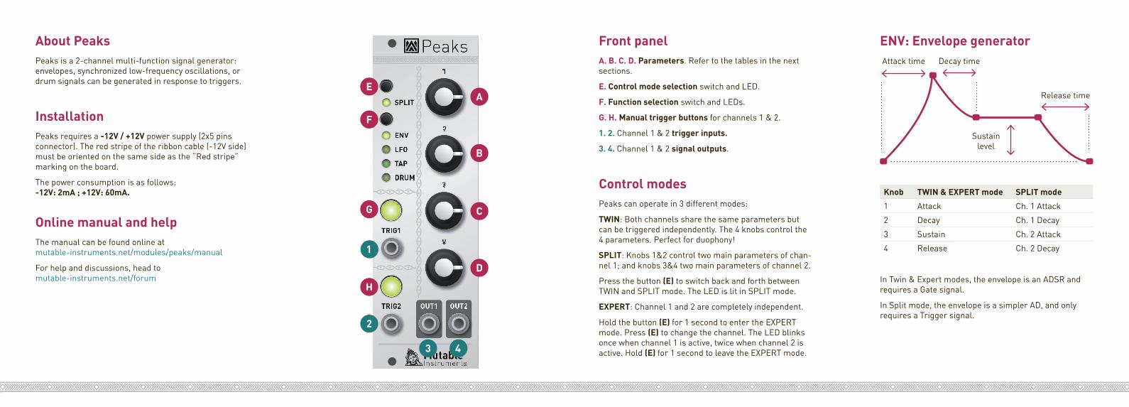
A
B
C
D
E
F
G
H
1
2
3 4
Front panel A. B. C. D. Parameters. Refer to the tables in the next sections.
E. Control mode selection switch and LED.
F. Function selection switch and LEDs.
G. H. Manual trigger buttons for channels 1 & 2.
1. 2. Channel 1 & 2 trigger inputs.
3. 4. Channel 1 & 2 signal outputs.
Control modesPeaks can operate in 3 different modes:
TWIN: Both channels share the same parameters but can be triggered independently. The 4 knobs control the 4 parameters. Perfect for duophony!
SPLIT: Knobs 1&2 control two main parameters of chan-nel 1; and knobs 3&4 two main parameters of channel 2.
Press the button (E) to switch back and forth between TWIN and SPLIT mode. The LED is lit in SPLIT mode.
EXPERT: Channel 1 and 2 are completely independent.
Hold the button (E) for 1 second to enter the EXPERT mode. Press (E) to change the channel. The LED blinks once when channel 1 is active, twice when channel 2 is active. Hold (E) for 1 second to leave the EXPERT mode.
ENV: Envelope generator
Knob TWIN & EXPERT mode SPLIT mode
1 Attack Ch. 1 Attack
2 Decay Ch. 1 Decay
3 Sustain Ch. 2 Attack
4 Release Ch. 2 Decay
In Twin & Expert modes, the envelope is an ADSR and requires a Gate signal.
In Split mode, the envelope is a simpler AD, and only requires a Trigger signal.
Attack time Decay time
Sustain level
Release time