analog bass drum workshop - wordpress.com to other gear so, you built the project, and the bass drum...
TRANSCRIPT
Analog Bass Drum workshop © Caspar Ockeloen-Korppi 23.11.2015
Helsinki Sound-electronics
In this workshop we will build a classic analog drum circuit. First we will build up the circuit step-by-step
on the breadboard, then have a short look at how it works.
Materials needed Breadboard, wires, 9V battery and battery clip
1 x LM358 (dual operational amplifier)
Capacitors: 1 x 10 uF, 4 x 100 nF
Resistors: 2 x 220 Ohm, 1 x 4.7k, 5 x 10k, 1 x 47k, 2 x 470k, 1 x 1M
Diode: 1 x 1N4148
Potentiometers: 1 x 10k, 1 x 100k (or 1M)
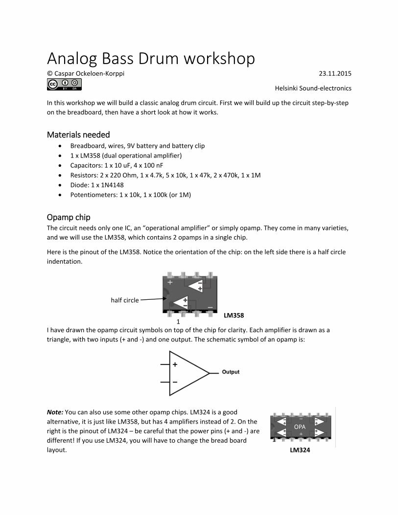
Opamp chip The circuit needs only one IC, an “operational amplifier” or simply opamp. They come in many varieties,
and we will use the LM358, which contains 2 opamps in a single chip.
Here is the pinout of the LM358. Notice the orientation of the chip: on the left side there is a half circle
indentation.
LM358
I have drawn the opamp circuit symbols on top of the chip for clarity. Each amplifier is drawn as a
triangle, with two inputs (+ and -) and one output. The schematic symbol of an opamp is:
Note: You can also use some other opamp chips. LM324 is a good
alternative, it is just like LM358, but has 4 amplifiers instead of 2. On the
right is the pinout of LM324 – be careful that the power pins (+ and -) are
different! If you use LM324, you will have to change the bread board
layout.
1
half circle
LM324
1
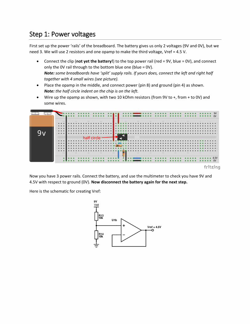
Step 1: Power voltages
First set up the power ‘rails’ of the breadboard. The battery gives us only 2 voltages (9V and 0V), but we
need 3. We will use 2 resistors and one opamp to make the third voltage, Vref = 4.5 V.
Connect the clip (not yet the battery!) to the top power rail (red = 9V, blue = 0V), and connect
only the 0V rail through to the bottom blue one (blue = 0V).
Note: some breadboards have ‘split’ supply rails. If yours does, connect the left and right half
together with 4 small wires (see picture).
Place the opamp in the middle, and connect power (pin 8) and ground (pin 4) as shown.
Note: the half circle indent on the chip is on the left.
Wire up the opamp as shown, with two 10 kOhm resistors (from 9V to +, from + to 0V) and
some wires.
Now you have 3 power rails. Connect the battery, and use the multimeter to check you have 9V and
4.5V with respect to ground (0V). Now disconnect the battery again for the next step.
Here is the schematic for creating Vref:
half circle
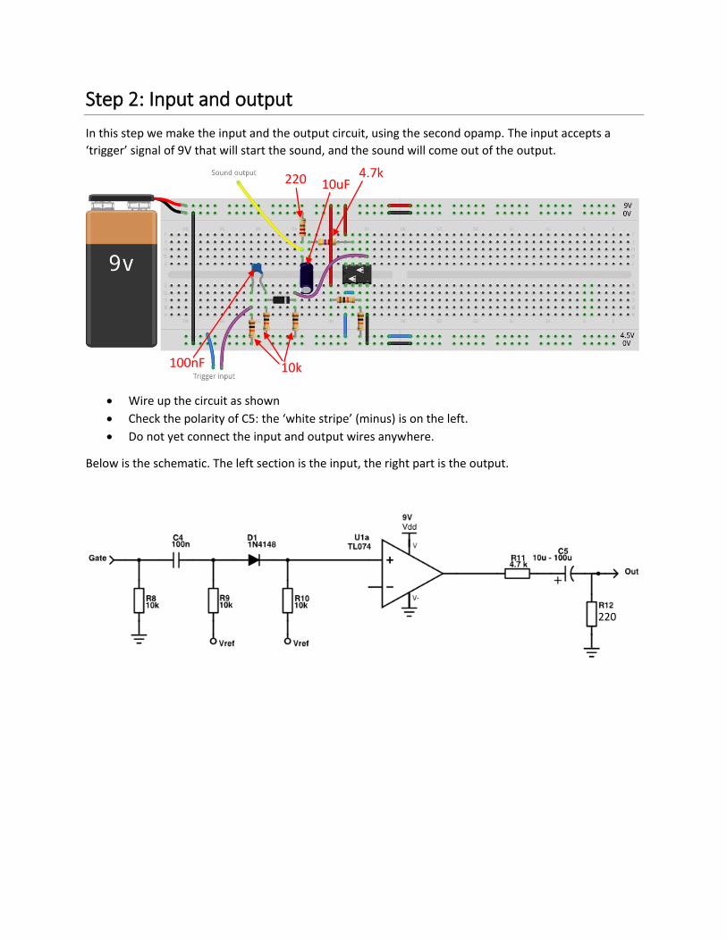
Step 2: Input and output
In this step we make the input and the output circuit, using the second opamp. The input accepts a
‘trigger’ signal of 9V that will start the sound, and the sound will come out of the output.
Wire up the circuit as shown
Check the polarity of C5: the ‘white stripe’ (minus) is on the left.
Do not yet connect the input and output wires anywhere.
Below is the schematic. The left section is the input, the right part is the output.
10k
10uF 220
100nF
4.7k
220

Step 3: Basic drum
Now it’s time to make some drums! This is the heart of the circuit: a filter between the output and –
input of the opamp.
Here is the schematic. Note that one leg of the potentiometer goes to 4.5V (Vref):
Now connect the output to an amplifier and loudspeaker, and plug in the battery. To kick the drum,
touch the input wires (purple & blue) together. You should hear a short drum sound, and the frequency
knob changes it from very low frequency (inaudible) to kind of a ‘tom’ sound.
If you are connecting this at home, read the connection tips at the end of the document first!
Tip: If you hear a continuous tone or noise, try adding an extra 100nF capacitor between the opamp ‘+’
and ‘-‘ power pins (pin 4 and pin 8). Also make the wires added in this step as short as possible.
10k
100nF
1M
220 Ohm
220
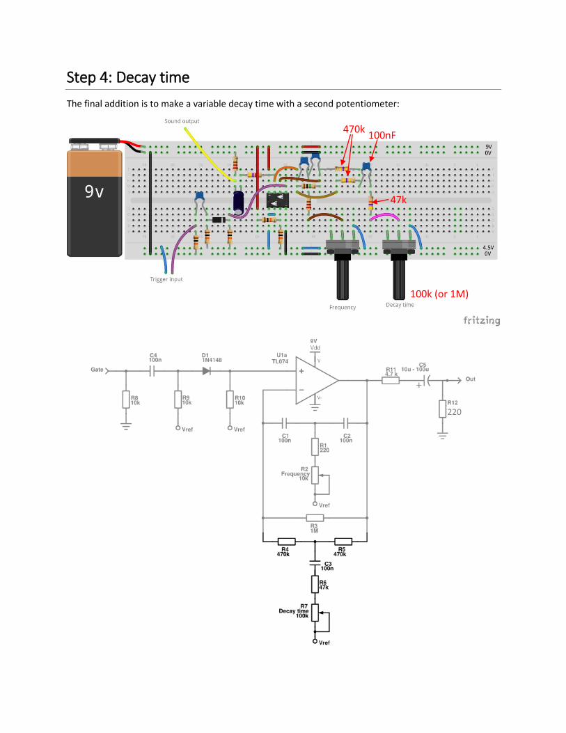
Step 4: Decay time
The final addition is to make a variable decay time with a second potentiometer:
470k 100nF
47k
100k (or 1M)
220
A bit about how it works
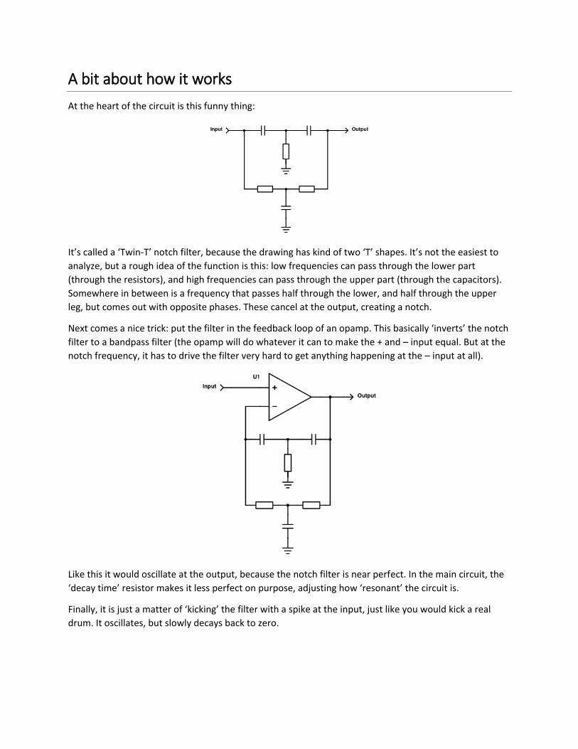
At the heart of the circuit is this funny thing:
It’s called a ‘Twin-T’ notch filter, because the drawing has kind of two ‘T’ shapes. It’s not the easiest to
analyze, but a rough idea of the function is this: low frequencies can pass through the lower part
(through the resistors), and high frequencies can pass through the upper part (through the capacitors).
Somewhere in between is a frequency that passes half through the lower, and half through the upper
leg, but comes out with opposite phases. These cancel at the output, creating a notch.
Next comes a nice trick: put the filter in the feedback loop of an opamp. This basically ‘inverts’ the notch
filter to a bandpass filter (the opamp will do whatever it can to make the + and – input equal. But at the
notch frequency, it has to drive the filter very hard to get anything happening at the – input at all).
Like this it would oscillate at the output, because the notch filter is near perfect. In the main circuit, the
‘decay time’ resistor makes it less perfect on purpose, adjusting how ‘resonant’ the circuit is.
Finally, it is just a matter of ‘kicking’ the filter with a spike at the input, just like you would kick a real
drum. It oscillates, but slowly decays back to zero.
Connecting to other gear
So, you built the project, and the bass drum is working well enough that you want to use it with other
gear. That’s easy, but there are a few things to take care of.
The trigger input The trigger input is designed for 4.5V trigger signals, but any trigger input up to 30V can be used safely.
The trigger can come for example from a drum computer or sequencer with ‘gate’ out, from an Arduino,
or even a ‘click track’ from DAW software.
The output Note: Be careful connecting self-built projects to inputs of other gear (sound cards, amplifiers, mixers…).
It’s possible to blow up the inputs!
If built exactly as shown, the bass drum output gives a voltage swing of up about +/- 25 mV. That is a
safe voltage for most equipment such as amplifier. Nevertheless, always turn the volume and input gain
of your amp or mixer completely down before connecting, and then slowly turn it up while playing the
drum until you hear something.
If the output of the bass drum is too quiet, you can increase
the value of R12 in steps until you are happy with the result.
For most cases, 1k should be enough.
The picture on the right shows how to connect a 3.5mm or 6mm jack socket to the output. Always
connect the signal (sound output wire) as well as the ground (0V rail)!
Making a eurorack module This goes beyond the scope of this workshop, but if you want to make this into a eurorack (or other) module, I
would recommend a few changes:
In eurorack you can power the opamp with +/- 12V, and you don’t need Vref. Leave out the Vref circuit,
and use ground everywhere instead of Vref. Also the ground points still go to ground.
Modular synthesizers use larger signal voltages. You can use quite a large value for R12, such as 4.7k or
10k, if you want to connect the output to a modular synth.
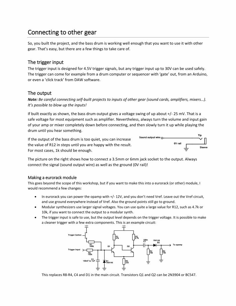
The trigger input is safe to use, but the output level depends on the trigger voltage. It is possible to make
a cleaner trigger with a few extra components. This is an example circuit:
This replaces R8-R4, C4 and D1 in the main circuit. Transistors Q1 and Q2 can be 2N3904 or BC547.