dr.arkan a.hussein power electronics fourth class
TRANSCRIPT

Operation and Analysis of the Three Phase Fully
Controlled Bridge Converter
Dr.Arkan A.Hussein Power Electronics Fourth Class
١

Instructional Objectives On completion the student will be able to
• Draw the circuit diagram and waveforms associated with a three phase fully controlled
bridge converter.
• Find out the average, RMS valves and the harmonic spectrum of the output voltage /
current waveforms of the converter.
• Find out the closed form expression of the output current and hence the condition for
continuous conduction.
• Find out the displacement factor, distortion factor and the power factor of the input
current as well as its harmonic spectrum.
• Analyze the operation of higher pulse number converters and dual converter.
• Design the triggering circuit of the three phase fully controlled bridge converter.
Dr.Arkan A.Hussein Power Electronics Fourth Class
٢

13.1 Introduction
The three phase fully controlled bridge converter has been probably the most widely used power
electronic converter in the medium to high power applications. Three phase circuits are
preferable when large power is involved. The controlled rectifier can provide controllable out
put dc voltage in a single unit instead of a three phase autotransformer and a diode bridge
rectifier. The controlled rectifier is obtained by replacing the diodes of the uncontrolled rectifier
with thyristors. Control over the output dc voltage is obtained by controlling the conduction
interval of each thyristor. This method is known as phase control and converters are also called
“phase controlled converters”. Since thyristors can block voltage in both directions it is possible
to reverse the polarity of the output dc voltage and hence feed power back to the ac supply from
the dc side. Under such condition the converter is said to be operating in the “inverting mode”.
The thyristors in the converter circuit are commutated with the help of the supply voltage in the
rectifying mode of operation and are known as “Line commutated converter”. The same circuit
while operating in the inverter mode requires load side counter emf. for commutation and are
referred to as the “Load commutated inverter”.
In phase controlled rectifiers though the output voltage can be varied continuously the load
harmonic voltage increases considerably as the average value goes down. Of course the
magnitude of harmonic voltage is lower in three phase converter compared to the single phase
circuit. Since the frequency of the harmonic voltage is higher smaller load inductance leads to
continuous conduction. Input current wave shape become rectangular and contain 5th
and higher
order odd harmonics. The displacement angle of the input current increases with firing angle.
The frequency of the harmonic voltage and current can be increased by increasing the pulse
number of the converter which can be achieved by series and parallel connection of basic 6 pulse
converters. The control circuit become considerably complicated and the use of coupling
transformer and / or interphase reactors become mandatory.
With the introduction of high power IGBTs the three phase bridge converter has all but been
replaced by dc link voltage source converters in the medium to moderately high power range.
However in very high power application (such as HV dc transmission system, cycloconverter
drives, load commutated inverter synchronous motor drives, static scherbius drives etc.) the basic
B phase bridge converter block is still used. In this lesson the operating principle and
characteristic of this very important converter topology will be discussed in source depth.
13.2 Operating principle of 3 phase fully controlled bridge converter
A three phase fully controlled converter is obtained by replacing all the six diodes of an
uncontrolled converter by six thyristors as shown in Fig. 13.1 (a)
Dr.Arkan A.Hussein Power Electronics Fourth Class
٣

Dr.Arkan A.Hussein Power Electronics Fourth Class
٤
For any current to flow in the load at least one device from the top group (T1, T3, T5) and one
from the bottom group (T2, T4, T6) must conduct. It can be argued as in the case of an
uncontrolled converter only one device from these two groups will conduct.
Then from symmetry consideration it can be argued that each thyristor conducts for 120° of the
input cycle. Now the thyristors are fired in the sequence T1 → T2 → T3 → T4 → T5 → T6 → T1
with 60° interval between each firing. Therefore thyristors on the same phase leg are fired at an
interval of 180° and hence can not conduct simultaneously. This leaves only six possible
conduction mode for the converter in the continuous conduction mode of operation. These are
T1T2, T2T3, T3T4, T4T5, T5T6, T6T1. Each conduction mode is of 60° duration and appears in the
sequence mentioned. The conduction table of Fig. 13.1 (b) shows voltage across different
devices and the dc output voltage for each conduction interval. The phasor diagram of the line
voltages appear in Fig. 13.1 (c). Each of these line voltages can be associated with the firing of a
thyristor with the help of the conduction table-1. For example the thyristor T1 is fired at the end
of T5T6 conduction interval. During this period the voltage across T1 was vac. Therefore T1 is
fired α angle after the positive going zero crossing of vac. Similar observation can be made about
other thyristors. The phasor diagram of Fig. 13.1 (c) also confirms that all the thyristors are fired
in the correct sequence with 60° interval between each firing.
Fig. 13.2 shows the waveforms of different variables (shown in Fig. 13.1 (a)). To arrive at the
waveforms it is necessary to draw the conduction diagram which shows the interval of
conduction for each thyristor and can be drawn with the help of the phasor diagram of fig. 13.1
(c). If the converter firing angle is α each thyristor is fired “α” angle after the positive going zero
crossing of the line voltage with which it’s firing is associated. Once the conduction diagram is
drawn all other voltage waveforms can be drawn from the line voltage waveforms and from the
conduction table of fig. 13.1 (b). Similarly line currents can be drawn from the output current
and the conduction diagram. It is clear from the waveforms that output voltage and current
waveforms are periodic over one sixth of the input cycle. Therefore this converter is also called
the “six pulse” converter. The input current on the other hand contains only odds harmonics of
the input frequency other than the triplex (3rd
, 9th
etc.) harmonics. The next section will analyze
the operation of this converter in more details.
Dr.Arkan A.Hussein Power Electronics Fourth Class
٥

Exercise 13.1
Fill in the blank(s) with the appropriate word(s)
i) The three phase fully controlled bridge converter is obtained by replacing six
_________ of an uncontrolled converter by six __________.
Dr.Arkan A.Hussein Power Electronics Fourth Class
٦
ii) The pulse number of a three phase fully controlled bridge converter is _________.
iii) In a three phase fully controlled converter each device conducts for an interval of
__________ degrees.
iv) In a three phase fully controlled converter operating in continuous conduction there
are ________ different conduction modes.
v) The output voltage of a three phase fully controlled converter operating in the
continuous conduction mode consists of segments of the input ac ________ voltage.
vi) The peak voltage appearing across any device of a three phase fully controlled
converter is equal to the ________ input ac ________ voltage.
vii) The input ac current of a three phase fully controlled converter has a ________ step
waveform.
viii) The input ac current of a three phase fully controlled converter contains only
_________ harmonics but no _________ harmonic.
ix) A three phase fully controlled converter can also operate in the _________ mode.
x) Discontinuous conduction in a three phase fully controlled converter is _________.
Answers: (i) diodes, thyristors; (ii) six; (iii) 120; (iv) six; (v) line; (vi) peak, line; (vii) six; (viii)
odd, tripler; (ix) inverting; (x) rare.
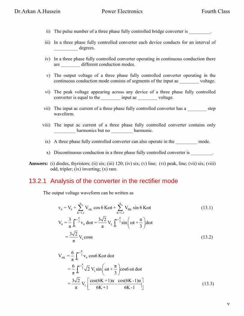
13.2.1 Analysis of the converter in the rectifier mode
The output voltage waveform can be written as
α α
0 0 AK BK
K=1,2 K=1,2
v = V + V cos 6 Kωt + V sin 6 Kωt∑ ∑ (13.1)
π πα+ α+3 3
0 0 Lα α
3 3 2 πV = v dωt = V sin ωt + dωt
π π 3
⎛ ⎞⎜ ⎟⎝ ⎠∫ ∫
L
3 2= V cosαπ
(13.2)
πα+3
AK 0α
6V = v cos6 Kωt dωt
π ∫
πα+3
Lα
6 π= 2 V sin ωt + cos6 ωt dωtπ 3
⎛ ⎞⎜ ⎟⎝ ⎠∫
L
3 2 cos(6K +1)α cos(6K -1)α= V -π 6K +1 6K -1
⎡ ⎤⎢ ⎥⎣ ⎦ (13.3)
Dr.Arkan A.Hussein Power Electronics Fourth Class
٧
πα+3
BK 0α
6V = v sin6 Kωt dωt
π ∫
πα+3
Lα
6 π= 2 V sin ωt + sin6 ωt dωtπ 3
⎛ ⎞⎜ ⎟⎝ ⎠∫
L
3 2 sin(6K +1)α sin(6K -1)α= V -π 6K +1 6K -1
⎡ ⎤⎢ ⎥⎣ ⎦ (13.4)
1
π 2α+23
0RMS 0 Lα
3 3V = v dωt = V 1+ cos2α
π 4π3⎡ ⎤⎢ ⎥⎣ ⎦∫
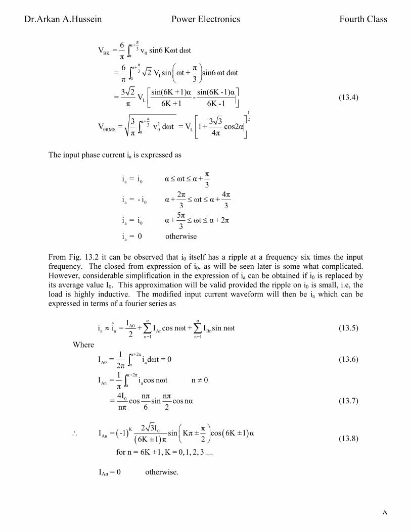
The input phase current ia is expressed as
a 0
πi = i α ωt α +
3≤ ≤
a 0
2π 4πi = - i α + ωt α +
3 3≤ ≤
a 0
5πi = i α + ωt α + 2π
3≤ ≤
ai = 0 otherwise
From Fig. 13.2 it can be observed that i0 itself has a ripple at a frequency six times the input
frequency. The closed from expression of i0, as will be seen later is some what complicated.
However, considerable simplification in the expression of ia can be obtained if i0 is replaced by
its average value I0. This approximation will be valid provided the ripple on i0 is small, i.e, the
load is highly inductive. The modified input current waveform will then be ia which can be
expressed in terms of a fourier series as
α α
A0a a An Bn
n=1 n=1
Iˆi i = + I cos nωt + I sin nωt2
≈ ∑ ∑ (13.5)
Where
α+2π
A0 aα
1I = i dωt = 0
2π ∫ (13.6)
α+2π
An aα
1I = i cos nωt n 0
π≠∫
04I nπ nπ= cos sin cos nα
nπ 6 2 (13.7)
( ) ( ) ( )K 0An
2 3I π I = -1 sin Kπ ± cos 6K ±1 α
6K ±1 π 2
for n = 6K ±1, K = 0, 1, 2, 3 ....
⎛ ⎞∴ ⎜ ⎟⎝ ⎠ (13.8)
IAn = 0 otherwise.
Dr.Arkan A.Hussein Power Electronics Fourth Class
٨

α+2π
Bn aα
1I = i sin nωt dωt
π ∫
04I nπ nπ= cos sin nα sin
nπ 6 2 (13.9)
( ) ( ) ( )K 0Bn
2 3I π I = -1 sin Kπ ± sin 6K ±1 α
6K ±1 π 2
for n = 6K ±1, K = 0, 1, 2, ....
⎛ ⎞∴ ⎜ ⎟⎝ ⎠ (13.10)
IBn = 0 otherwise.
( )( ) ( )(Kα
0
a
K=0
-1 2 3I π i = sin Kπ ± cos 6K ±1 ωt -α
6K ±1 π 2
⎛ ⎞ )∴ ⎡ ⎤⎜ ⎟ ⎣ ⎦⎝ ⎠∑ (13.11)
in particular ia1 = fundamental component of ia
(0
2 3= I cos ωt -απ
) (13.12)
From Fig. 13.2 Lan
2Vv = cos ωt
3 (13.13)
∴ displacement angle φ = α. ∴ displacement factor = cosα (13.14)
distortion factor =
0I
a10
a
I 6 2=
π 3 πI
⎛ ⎞⎜ ⎟⎝ ⎠3
I = (13.15)
∴ Power factor = Displacement factor × Distortion factor = 3
cosαπ
(13.16)
The closed form expression for i0 in the interval πα ωt α +3
≤ ≤ can be found as follows
in this interval
00 0 L
di πRi + L + E = v = 2V sin ωt +
dt 3
⎛⎜⎝ ⎠⎞⎟ (13.17)
( )ωt - α-
tanφ L0 1
2V π Ei = I e + sin ωt + -φ -
Z 3
⎛ ⎞⎜ ⎟⎝ ⎠ R (13.18)
Where 2 2 2 ωLZ = R +ω L , tanφ =
R
L R = Zcosφ, E = 2V sinθ∴ (from Fig. 13.2) (13.19)
Dr.Arkan A.Hussein Power Electronics Fourth Class
٩
( )ωt - α-
tanφ L0 1
2V π sinθ i = I e + sin ωt + -φ -
Z 3 c φ⎡ ⎤⎛ ⎞
os∴ ⎜ ⎟⎢ ⎝ ⎠⎣ ⎦⎥ (13.20)
Since i0 is periodic over π/3
π0 0ωt=α ωt=α+3
i = i (13.21)
L1
π-
3tanφ L1
2V π sinθ I + sin α + -φ -
Z 3 cosφ
2V 2π sinθ = I e + sin α + -φ -
Z 3 c φ
⎡ ⎤⎛ ⎞
os
∴ ⎜ ⎟⎢ ⎥⎝ ⎠⎣ ⎦⎡ ⎤⎛ ⎞⎜ ⎟⎢ ⎥⎝ ⎠⎣ ⎦
OR ( )
L1 π
- 3tanφ
sin φ -α2VI =
Z1- e
(13.22)
( ) ( )t - -
tanφL0 π
- 3tanφ
sin φ -α2V π sinθ i = e + sin t + -φ -
Z 3 φ1- e
ω α ω⎡ ⎤⎛ ⎞⎢ ⎥cos
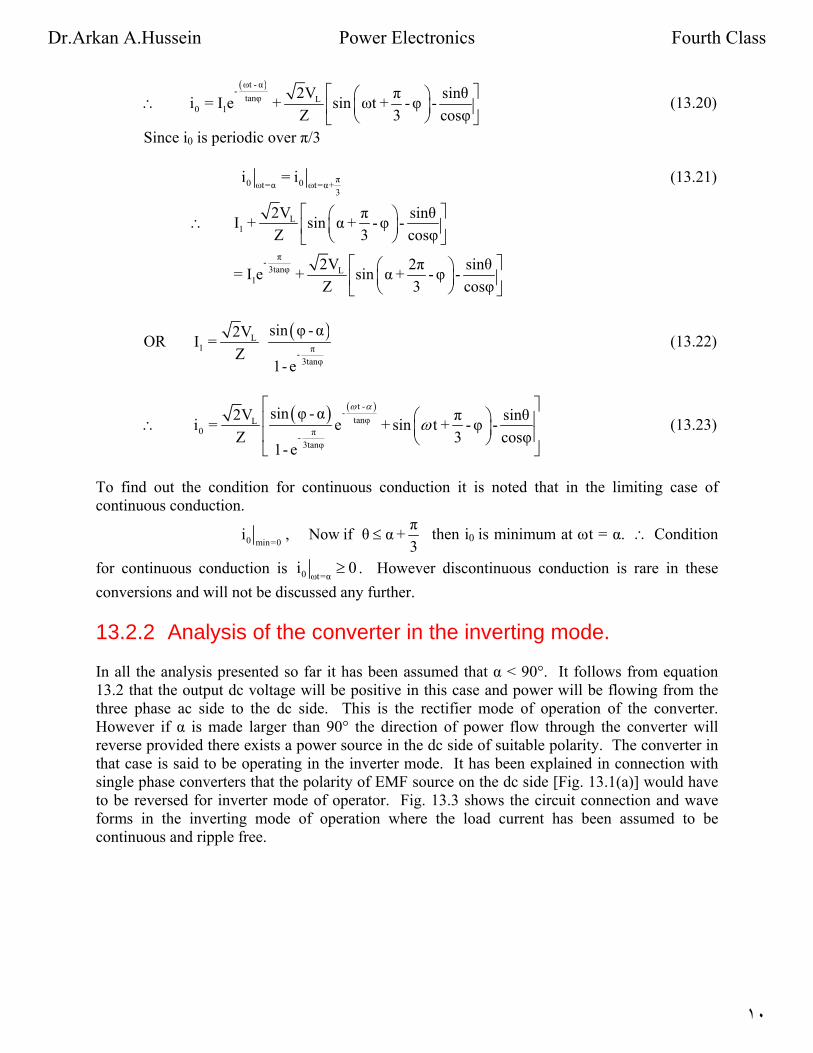
∴ ⎜ ⎟⎢ ⎥⎝ ⎠⎣ ⎦ (13.23)
To find out the condition for continuous conduction it is noted that in the limiting case of
continuous conduction.
0 min=0
πi , Now if θ α +
3≤ then i0 is minimum at ωt = α. ∴ Condition
for continuous conduction is 0 ωt=αi ≥ 0 . However discontinuous conduction is rare in these
conversions and will not be discussed any further.
13.2.2 Analysis of the converter in the inverting mode.
In all the analysis presented so far it has been assumed that α < 90°. It follows from equation
13.2 that the output dc voltage will be positive in this case and power will be flowing from the
three phase ac side to the dc side. This is the rectifier mode of operation of the converter.
However if α is made larger than 90° the direction of power flow through the converter will
reverse provided there exists a power source in the dc side of suitable polarity. The converter in
that case is said to be operating in the inverter mode. It has been explained in connection with
single phase converters that the polarity of EMF source on the dc side [Fig. 13.1(a)] would have
to be reversed for inverter mode of operator. Fig. 13.3 shows the circuit connection and wave
forms in the inverting mode of operation where the load current has been assumed to be
continuous and ripple free.
Dr.Arkan A.Hussein Power Electronics Fourth Class
١٠

Dr.Arkan A.Hussein Power Electronics Fourth Class
١١
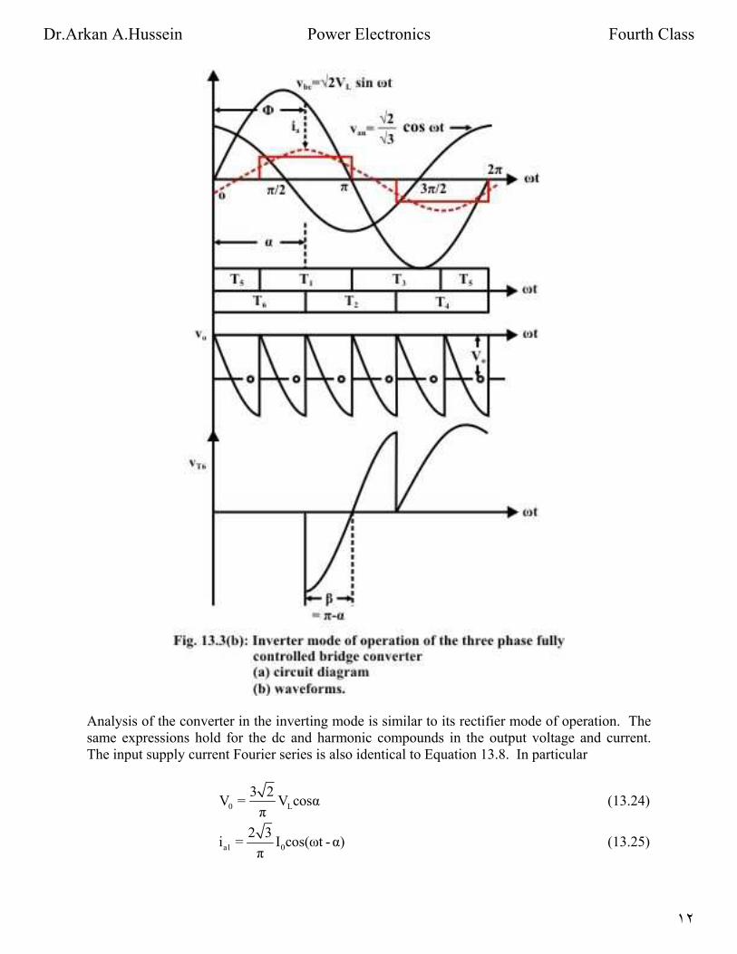
Analysis of the converter in the inverting mode is similar to its rectifier mode of operation. The
same expressions hold for the dc and harmonic compounds in the output voltage and current.
The input supply current Fourier series is also identical to Equation 13.8. In particular
0 L
3 2V = V cosα
π (13.24)
a1 0
2 3i = I cos(ωt -α)
π (13.25)
Dr.Arkan A.Hussein Power Electronics Fourth Class
١٢
For values of α in the range 90° < α < 180° it is observed from Fig. 13.3(b) that the average dc
voltage is negative and the displacement angle φ of the fundamental component of the input ac
line current is equal to α > 90°. Therefore, power in the ac side flows from the converter to the
source.
It is observed form Fig. 13.3(b) that an outgoing thyristor (thyristor T6 in Fig. 13.3(b)) after
commutation is impressed with a negative voltage of duration β = π – α. For successful
commutation of the outgoing thyristor it is essential that this interval is larger than the turn off
time of the thyristor i.e,
β ωtq≥ , tq is the thyristor turn off time
Therefore π -α ωtq or α π -ωtq ≥ ≤ .
Which imposes an upper limit on the value of α. In practice this upper value of α is further
reduced due to commutation overlap.
Exercise 13.2
1. A three phase fully controlled bridge converter operating from a 3 phase 220 V, 50 Hz
supply is used to charge a battery bank with nominal voltage of 240 V. The battery bank
has an internal resistance of 0.01 Ω and the battery bank voltage varies by ± 10% around
its nominal value between fully charged and uncharged condition. Assuming continuous
conduction find out.
(i) The range of firing angle of the converter.
(ii) The range of ac input power factor.
(iii) The range of charging efficiency.
When the battery bank is charged with a constant average charging current of 100 Amps through
a 250 mH lossless inductor.
Answer: The maximum and minimum battery voltages are, VB Min = 0.9 × VB Nom = 216 volts
and VB Max = 1.1 × VB Nom = 264 volts respectively.
Since the average charging current is constant at 100 A.
V0 Max = VB Max + 100 × RB = 264 + 100 × 0.01 = 265 volts
V0 Min = VB Min + 100 × RB = 216 + 100 × 0.01 = 217 volts.
(i) But 0 Max L Min
3 2V = V cos α
π ∴ α Min = 26.88º
0 Min L Max
3 2V = V cos α
π ∴ α Max = 43.08º
(ii) Input power factor is maximum at minimum α and vice versa
Dr.Arkan A.Hussein Power Electronics Fourth Class
١٣

∴ Max min
3p.f. max = Distortion factor Displacement factor = ×cos α = 0.85
π×
Max
3p.f. Min = ×cos α = 0.697
π
(iii) Power loss during charging = 2
0RMs BI R
But 2 2 2 2
0RMs 0 1 2I I + I + I +........= and
2 2AK BKK
K
V + VVI =
6KωL 6 2KωL≈
For α = α Min
VA1 = 0.439 V, VB1 = 48.48 V, I1 = 0.073 Amps
VA2 = 10.76, VB2 = 20.15 V, I2 = 0.017 Amps.
∴ 2 2 2 2
0RMsJ 100 + (0.073) + (0.017) = 10000.00562≈
∴ Ploss = 100 watts.
At α Min, P0 = I0 × VB Max = 26400 watts.
∴ Charging efficiency = 26400
26400 + 100 = 99.6%
Similarly for α Max, 2 2
0RMs 0I I≈
∴ Ploss = 100 watts
P0 = I0 × VB Min = 21600 watts.
∴ Charging efficiency = 21600
21600 + 100 = 99.54%
2. A three phase fully controlled converter operates from a 3 phase 230 V, 50 Hz supply
through a Y/Δ transformer to supply a 220 V, 600 rpm, 500 A separately excited dc
motor. The motor has an armature resistance of 0.02 Ω. What should be the transformer
turns ratio such that the converter produces rated motor terminal voltage at 0º firing
angle. Assume continuous conduction. The same converter is now used to brake the
motor regeneratively in the reverse direction. If the thyristors are to be provided with a
minimum turn off time of 100 μs, what is the maximum reverse speed at which rated
braking torque can be produced.
Answer: From the given question
L
3 2V = 220
π ∴ VL = 162.9 V
Where VL is the secondary side line and also the phase voltage since the secondary
side is Δ connected.
Dr.Arkan A.Hussein Power Electronics Fourth Class
١٤
Primary side phase voltage = 230
V3
= 132.79 V
∴ Turns ratio = 132.79
1:1.2267162.9
= .
During regenerative braking in the reverse direction the converter operates in the
inverting mode.
Mintq =100μS ∴ oMin Minβ = ωtq =1.8
∴ α Max = 180 – β Min = 178.2º
∴ Maximum negative voltage that can be generated by the converter is
oL
3 2V cos 178.2 = - 219.89 V
π
For rated braking torque Ia = 500 A
∴ Eb = Va – Iara = - 229.89 V.
At 600 RPM Eb = 220 – 500 × 0.02 = 210 V.
∴ Max reverse speed is 229.89
×600 = 656.83 RPM210
.
13.3 Higher pulse number converters and dual converter
The three phase fully controlled converter is widely used in the medium to moderately high power
applications. However in very large power applications (such as HV DC transmission systems)
the device ratings become impractically large. Also the relatively low frequency (6th
in the dc
side, 5th
and 7th
in the ac side) harmonic voltages and currents produced by this converter become
unacceptable. Therefore several such converters are connected in series parallel combination in
order to increase the voltage / current rating of the resulting converter. Furthermore if the
component converters are controlled properly some lower order harmonics can be eliminated both
from the input and output resulting in a higher pulse converter.
Dr.Arkan A.Hussein Power Electronics Fourth Class
١٥

Fig. 13.4(a) schematically represents series connection of two six pulse converters where as Fig.
13.4(b) can be considered to be a parallel connection. The inductance in between the converters
has been included to limit circulating harmonic current. In both these figures CONV – I and
CONV – II have identical construction and are also fired at the same firing angle α. Their input
supplies also have same magnitude but displaced in phase by an angle φ. Then one can write
α
01 L AK BK
K=1 K=1
3 2v = V cosα + V cos 6 Kωt + V sin 6 Kωt
π
∞∑ ∑ (13.26)
Dr.Arkan A.Hussein Power Electronics Fourth Class
١٦

( ) (α α
02 L AK BK
K=1 K=1
3 2v = V cosα+ V cos 6 K ωt - + V sin 6 K ωt -
π)φ φ∑ ∑ (13.27)
Therefore for Fig 13.4(a)
( ) ( )0 01 02 L
α
AK BK
K=1
6 2v = v + v = V cosα +
π
2 cos3K V cos3K 2ωt - + V sin3K 2ωt -φ φ⎡ ⎤⎣ ⎦∑ φ (13.28)
Now if cos 3Kφ = 0 for some K then the corresponding harmonic disappear from the fourier
series expression of v0.
In particular if φ = 30° then cos 3Kφ = 0 for K = 1, 2, 3, 5…….
This phase difference can be obtained by the arrangement shown in Fig. 13.4(c).
Then
[ ]α
0 L Am Bm
m=1
6 2v = V cosα+ 2 V cos 12mωt + V sin 12mωt
π ∑ (13.29)
It can be seen that the frequency of the harmonics present in the output voltage has the form
12ω, 24ω, 36ω ………..
Similarly it can be shown that the input side line current iABC have harmonic frequency of the
form
11ω, 13ω, 23ω, 25ω, 35ω, 37ω, ………….
Which is the characteristic of a 12 pulse converter.
In a similar manner more number of 3 phase 6 pulse converters can be connected in series /
parallel and the φ angle can be adjusted to obtain 18 and 24 pulse converters.
One of the shortcomings of a three phase fully controlled converter is that although it can
produce both positive and negative voltage it can not supply current in both directions.
However, some applications such as a four quadrant dc motor drive require this capability from
the dc source. This problem is easily mitigated by connecting another three phase fully
controlled converter in anti parallel as shown in Fig. 13.5 (a). In this figure converter-I supplies
positive load current while converter-II supplies negative load current. In other words converter-
I operates in the first and fourth quadrant of the output v – i plane whereas converter-II operates
in the third and fourth quadrant. Thus the two converters taken together can operate in all four
quadrants and is capable of supplying a four quadrant dc motor drive. The combined converter is
called the Dual converter.
Dr.Arkan A.Hussein Power Electronics Fourth Class
١٧

Obviously since converter-I and converter-II are connected in antiparallel they must produce the
same dc voltage. This requires that the firing angles of these two converters be related as
α2 = π – α1 (13.30)
Dr.Arkan A.Hussein Power Electronics Fourth Class
١٨
Although Equations 13.30 ensures that the dc voltages produced by these converters are equal
the output voltages do not match on an instantaneous basis. Therefore to avoid a direct short
circuit between two different supply lines the two converters must never be gated
simultaneously. Converter-I receives gate pulses when the load current is positive. Gate pulses
to converter-II are blocked at that time. For negative load current converter-II thyristors are fired
while converter-I gate pulses are blocked. Thus there is no circulating current flowing through
the converters and therefore it is called the non-circulating current type dual converter. It
requires precise sensing of the zero crossing of the output current which may pose a problem
particularly at light load due to possible discontinuous conduction. To overcome this problem an
interphase reactor may be incorporated between the two converters. With the interphase reactor
in place both the converters can be gated simultaneously with α2 = π – α1. The resulting
converter is called the circulating current type dual converter.
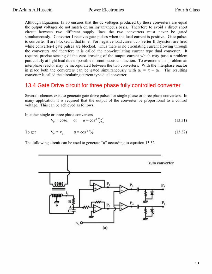
13.4 Gate Drive circuit for three phase fully controlled converter
Several schemes exist to generate gate drive pulses for single phase or three phase converters. In
many application it is required that the output of the converter be proportional to a control
voltage. This can be achieved as follows.
In either single or three phase converters
0
1
V-1K0V cosα or α = cos∝ (13.31)
To get cV-1K0 cV v α = cos∝ (13.32)
The following circuit can be used to generate “α” according to equation 13.32.
Dr.Arkan A.Hussein Power Electronics Fourth Class
١٩

In the circuit of Fig. 13.6(a) a phase shift network is used to obtain a waveform leading vi by 90º.
The phasor diagram of the phase shift circuit is shown in Fig. 13.6(b). The output of the phase
shift waveform (and its inverse) is compared with vc. The firing pulse is generated at the point
when these two waveforms are equal. Obviously at-this instant
c
s
v-1Vc sv V cosα or α = cos∝ (13.33)
Therefore this method of generation of converter firing pulses is called “inverse cosine” control.
The output of the phase shift network is called carrier waveform.
Similar technique can be used for three phase converters. However the phase shift network here
consists of a three phase signal transformer with special connections as shown in Fig. 13.7.
Dr.Arkan A.Hussein Power Electronics Fourth Class
٢٠

Dr.Arkan A.Hussein Power Electronics Fourth Class
٢١

The signal transformer uses three single phase transformer each of which has two secondary
windings. The primary windings are connected in delta while the secondary windings are
connected in zigzag. From Fig. 13.1 (c) T2 is fired α angle after the positive going zero crossing
of vbc. Therefore, to implement inverse cosine the carrier wave for T2 must lead vbc by 90º. This
waveform is obtained from zigzag connection of the winding segments a1a2 and c1c2 as shown in
Fig. 13.7(a). The same figure also shows the zigzag connection for other phase. The voltage
across each zigzag phase can be used to fire two thyristors belonging to the same phase leg using
a circuit similar to Fig. 13.6 (a). The phase shift network will not be required in this case.
Dr.Arkan A.Hussein Power Electronics Fourth Class
٢٢

Exercise 13.3
1. Fill in the blank(s) with the appropriate word(s)
i) Higher pulse number converters can be realized by __________ and _______
connection of six pulse converters.
ii) Constituent six pulse converters of a 12 pulse converter have _________ firing
angles.
iii) The input supply voltages to the converters of a 12 pulse converter have ________
magnitudes and are phase shifted from one another by _________ degrees.
iv) The input supply to a 12 pulse converter can be obtained through a _________
connected transformer.
v) Dual converters are used for supplying ________ quadrant dc motor drives.
vi) In a dual converter if one converter is fired at an angle ‘α’ the other has to be fired
at _________.
vii) In ___________ current dual converter only one converter conducts at any time.
viii) In a circulating current type dual converter an __________ is used between the
converters to limit the circulating current.
ix) To obtain a linear control relation between the control voltage and the output dc
voltage of a converter ___________ control logic is used.
x) In a three phase fully controlled converter the carrier waves for firing pulse
generation are obtained using three ___________ connected single phase
transformers.
Answers: (i) Series, parallel; (ii) same, (iii) equal, 30, (iv) star – star – delta; (v) four; (vi) π - α,
(vii) non-circulating ; (viii) inductor, (ix) inverse-cosine; (x) delta-zigzag.
2. A 220V, 750 RPM, 200A separately excited dc motor has an armature resistance of 0.05
Ω. The armature is fed from a three phase non circulating current dual converter. If the
forward converter operates at a firing angle of 70º
i) At what speed will the motor deliver rated torque.
ii) What should be the firing angle in the regenerative braking mode when the motor
delivers half the rated torque at 600 rpm.
Assume continuous conduction. Supply voltage is 400 V.
Answer:
i) The output voltage = o3 2400 cos 70 = 184.7 V
π×
Dr.Arkan A.Hussein Power Electronics Fourth Class
٢٣
∴ Eb = Va – Iara = 184.7 – 200 × 0.05 = 174.75 V.
∴ Operating speed = 174.75
×750 = 624 RPM220 - 0.05 200× .
ii) b 600RPM 1 a
600E = - × 210 = -168V I = 100A
750
∴ Va = - Eb + Iara = – 173 r.
Va = - 173 = 3 2
400 cos απ
∴ α = 108.67º
3. What will happen if the signal transformers generating the carrier wave have delta –
double star connection instead of delta-zigzag connection.
Answer: With delta-double star connection of the signal transformers the carrier wave forms
will be in phase with the line voltage waveforms. Therefore, without a phase shift
network it will not be possible to generate carrier waveforms which are in quadrature
with the line voltages. Hence inverse casine control law cannot be implemented.
References
1. “Power Electronics”; P.C. Sen; Tata-McGrawhill publishing company limited; 1995.
2. “Power Electronics, Converters, Applications and Design”, Mohan, Undeland, Robbins;
John Willey and Sons Inc; Third Edition, 2003.
Dr.Arkan A.Hussein Power Electronics Fourth Class
٢٤