draper pick-up front operators manual and parts catalogue · 2016-06-24 · on a new pick-up:...
TRANSCRIPT

1
DRAPER PICK-UP FRONT OPERATORS MANUAL AND PARTS CATALOGUE TABLE OF CONTENTS OPERATORS MANUAL 3 1. NOTES ON WINDROWS HANDLING 4 1.1 Canola 4 1.2 Cereals 4 1.3 Lupins 5 2. FOR THE FIRST TIME FITTING 2.1 Preparation for Fitting 6 2.2 Fitting 6 2.3 Locks 6 2.4 Drive Shaft 6 CHECKS 2.5 Hydraulics 7 2.6 Roller Settings 7 2.7 Belt Joining and Tension 7 2.8 Adjusting Belt Tension 8 2.9 Chain Tension 8 2.10 Tyre Pressure 10 3. SETTING UP 9 3.1 Gauge Wheel Height - Notes on Settings 9 3.2 Stubble Guard Height 9 3.3 Wind Guard 9 3.4 Pick-up Flotation 10 3.5 Table Auger Height 10 3.6 Retractable Fingers 10 3.7 Clutch Settings 10 3.8 P.T.O Drive Shaft 11 3.9 Crop Variations - Canola 11 3.10 Crop Variations - Cereals 12 3.11 Crop Variations - Lupins 13 4. OPERATING 14 4.1 Draper Belt Speed 14 4.2 Picking Up Windrows 14 4.3 Handling Lumps 14 4.4 Handling Obstructions 15 4.5 Reverse Feeding 15 4.6 Tyres & Anti Flutter 15

2
TABLE OF CONTENTS Cont. 5. SERVICE 16 Checks 5.1 Tyres & Wheels 16
5.2 Draper Belts 16 5.3 Sprockets & Chains 16 5.4 Bearings 16 5.5 Safety Covers 16 5.6 Hinges 16 5.7 Table Auger 17 5.8 Drive Slip Clutch 17 5.9 Clutch Lay Shaft 17 5.10 P.T.O Drive Shaft 17 5.11 Wind Guard 17 6. COMBINE ADAPTORS 18 7. SAFETY 19 7.1 Guards 19 7.2 Operating 19 8. LUBRICATION CHART 20 9. SPECIFICATIONS 20 10. LUBRICATION POINTS 21 PARTS CATALOGUE 23 BOLT LIST 35

3
OPERATORS MANUAL

4
1. NOTES ON WINDROW HANDLING Harvesting rates and combine efficiency is very much controlled by the way windrows are made. It is readily understood that slowing to handling a windrow lump or obstruction, then increasing speed back to the original, will cause unnecessary grain loss; and that being restricted to a less than maximum capacity speed because the windrows have been poorly made, will add to the cost of harvesting; to say nothing of the downtime loss from a drum or rotor block or breakdown. This then is good reason to understand and use correct techniques for making good windrows. Windrowing techniques will differ for Canola, Lupins and Cereals, therefore the following tips may be worth noting. If it is planned to windrow cereals or lupins in stony country the dangers and likelihood of picking up stones should be taken into account when making such a decision. 1.1 CANOLA If a pick-up front is going to be used on the combine, it is more important to form a suitable row than if picking up with an open front; for the best utilisation of a pick up, the windrow should be lying as flat as possible in a “tiered” form with the heads facing rearward. This can only be achieved by cutting the crop approximately half way between the bottom plant laterals and the ground; this reduced height of stubble, and slightly longer stalk on the plant will produce a row with a formation that will hold it’s form as the pick-up belts lift and change the crop angle of approach to the combine table auger. On the other hand, if picking up with an open front, this laid back ‘tiered’ effect is not as important, but would still help as an advantage for efficient feeding. EXCESSIVE WINDROWER SPEED IS THE PRIME CAUSE OF POOR WINDROWS. Excessive speed tends to drag the crop heads, and leave the stalks trailing behind, effectively tipping the windrow to face the direction of travel, which means a “STALKS FIRST” feed for the pick-up or combine table which will slow the harvest rate. Unsuitable windrowers will also cause lumps, uneven density and poor construction which slows the rate and adds to the harvest cost. Ref 4.2 PICKING UP WINDROWS, page 14. Exception to the rule: In light and short stalked crops, the cutting height and therefore the stubble length should be regulated to suit the need to hold the crop against the effect of wind. 1.2 CEREAL Ideally good rows are made with the use of a “MIXER BELT” attached to the windrower to power feed the crop through the window; this effectively fluffs and mixes the straw giving it a consistency that is more likely to be supported by stubble which ideally should be cut 150 - 200mm high and at the same time form a thatched row which can help in rain. It is quicker to dry with less likelihood of grain damage and is much easier to pick up.

5
Without the benefit of a mixer, the windrower should be set to effectively CROSS or HERRINGBONE the lie of the straw to give as much as possible the same effect. If straw is left lying parallel to the sowing rows it will drop onto the ground and will be hard and slow to pick up; slower drying after rain will increase the possibility of the grain sprouting. Wide row spacing makes it hard to keep the crop up on the stubble. Individual windrower operator’s manuals will explain the adjustments required for making cereal windrows. The general principal is to run the reel and draper belts faster than normal relative to ground speed to get the crop heads onto the draper with positive contact to slow the straw and therefore criss cross the heads as they fall to form the windrow. For windrowers that have alternative width draper drive roller settings and have been set up for canola it may be necessary to lengthen the drapers and close the roller spacing to form a more compact windrow. 1.3 LUPINS Timing is the most critical; windrowing too late as the crop starts to dry can cause pods to snap off; they may not be lying on the ground in full view, but by looking under the row, the full extent of damage may be found; if a high percentage of crop is too mature, cutting late at night with minimal use of the reel should help avoid potential losses. Cutting height is not critical providing it is low enough to take the bottom pods; however, short stubble in particular, but lupin stubble generally is very damaging to implement tyres. A pick-up front is almost essential for handling the row into the combine. _____________________________________________________________

6
2. FOR THE FIRST TIME FITTING When fitting a Countrywide Pick-up Front to a combine for the first time, check the following: 2.1 PREPARATION FOR FITTING Turn the table auger to a point where the canopy over the combine front elevator chains cannot come in contact with the full-height table auger flight, if for some reason the canopy is non standard of if it has been damaged in any way, this precaution may avoid potential damage to the auger flight or combine. 2.2 FITTING When driving the combine into the front, set the elevator height to just fit under the top beam of the window. Do not drive into the front any more than is necessary to pick up the front. Raise the elevator carefully checking that the top beam of the window has settled into the lifting point of the elevator housing and that there are no parts of the window, bottom hooks, table auger cutoff plates, table auger or drive shaft catching up on the combine elevator housing as it is being raised. After fitted, check alignment of the floor and window sides and position of the cutoff plates which should end just before or in line with the elevator sides. Rotate table auger by hand to confirm clearances of flighting to elevators and dust canopy over the elevators. 2.3 LOCKS Adjust the bottom locks and engage. SAFETY FIRST....ENSURE THAT THE FRONT ELEVATOR LIFT RAM SAFETY LOCKS ARE INSTALLED BEFORE WORKING ON THE BOTTOM LOCKS OR UNDER ANY PART OF THE FRONT. 2.4 DRIVE SHAFT Depending on the make of combine as to the type of drive shaft. For straight rigid shaft fittings e.g. JD, alignment adjustments are made after the table is fitted, by the up and down, in and out mounting of the rear clutch drive lay shaft, taking care to ensure that the alignment is accurate. For P.T.O shaft drives ensure that the shaft is the correct length; if there is doubt about the length, separate the two halves, connect each half to the shafts, hold halves side by side and note the amount of overlap. A minimum of 100mm of overlap is preferred. If the shaft is too long then it will not be possible to fit the yoke onto the elevator drive jack shaft. Shorten the male or female part of the assembly and safety cover sufficiently to overcome the fitting problem.

7
CHECKS 2.5 HYDRAULICS It should never be assumed that the male and female couplings are fitted to the correct hoses. On a new Pick-up: Having coupled up the P.T.O shaft, connect the hydraulic hoses to the reel drive couplings, start the combine and engage the main function drive at idle revs. The elevator drive should then be engaged very briefly to check the direction of rotation of the belts. If the pick-up belts are rotating towards the operator, the fitting is correct and the minimum to maximum operating range of speeds via the reel speed control may be checked at operating engine revs. If the belts show signs of starting to turn backwards, stop the drive immediately, stop the combine and swap the hydraulic hoses on the motor. Uncouple both the hoses from the combine, unbolt the hose clamps, uncouple the swivel nut fitting to the drive motor and swap the hoses. Re-clamp the hoses ensuring that the same amount of hose slack is maintained as previously set so that when raised off the ground, the hoses still maintain some slack from the table to the pick- up. Re-couple the hoses to reel drives. Start the combine and recheck for correct rotation. Note: allowing the belts to turn backwards could damage tines. 2.6 ROLLER SETTINGS The draper roller pairs must be set parallel to each other (EQUAL DISTANCE AT BOTH ENDS, MEASURING THE SPINDLES FROM CENTRE TO CENTRE) to ensure that the draper belts run true between the washer dividers. 2.7 BELT JOINING AND TENSION
The belt ends are overlapped with the top lap trailing the direction of travel and are joined with special bolts. To make a good join it is important to have the width of the belt sitting flat whilst the bolts are being tightened - avoid over tightening the nuts. FOR MAXIMUM BELT LIFE AND GOOD FIELD PERFORMANCE, MAINTAINING CORRECT BELT TENSION IS IMPORTANT. To check correct belt tension, push the centre of the LH and RH outside belts down using moderate pressure to touch the channel frame member running through the centre of the belts. The outside belts only should be used to gauge correct tension. If the middle belts are definitely too slack, it may be necessary to swap them with outside belts.

8
Note: Insufficient tension reduces belt life and belts may stall under heavy load e.g. canola lumps, uncut crop, grass and weeds. Excessive tension will over tighten each end belt and in doing so, will spring the rollers making the centre belts looser. 2.8 ADJUSTING BELT TENSION 1) Slacken the roller drive chain. 2) Unlock the adjuster nuts on the jack bolts at each end of the tensioner roller and
back the nuts off equally both sides. 3) Loosen the bearing block retainer bolts. 4) Tighten the tensioner nuts equally both sides until the correct belt tension is
achieved. 5) Tighten bearing block bolts, jack bolt nuts and finally retension the drive chain. If after a prolonged period of not being used, some of the rear belts don’t turn on start-up, check that there are no rat’s nests between the belts. If not, remove the P.T.O drive shaft from the elevator drive jack shaft to disable the table auger. Rum the Front at idle speed and have a second person prod the stationary belt with a long stick e.g.: broom handle, to start the belt moving. After a short period the kink in the belt causing the problem will disappear and the belt will continue to run. Stop the elevator drive and recouple the P.T.O drive. AS A MATTER OF PERSONAL SAFETY, THE TABLE AUGER MUST NOT BE RUNNING WHEN CARRYING OUT THIS PROCEEDURE 2.9 CHAIN TENSION Whenever the pick-up belts are to be tensioned, it is necessary to first slacken the drive chain on that roller group. When tensioning the drive chains, check each span of the chain from one sprocket to the next, and adjust until there is some slack in one span. CHECK TO ENSURE THAT SPROCKET CONE GRUB SCREWS ARE TIGHT. THIS CHECK MUST BE CARRIED OUT AGAIN AFTER THE FIRST 25 Ha OF HARVESTING WITH A NEW PICK-UP FRONT 2.10 TYRE PRESSURE Avoid over inflation, set tyre pressure at approximately 70 kpa (10 to 12 PSI). This will absorb some of the effects of rough ground.

9
3. SETTING UP
3.1 GAUGE WHEEL HEIGHT The front roller height setting will need to be set to suit the type of crop stubble and ground conditions. Height adjustment is made by arranging the position of spacer collars on the castor wheel stauntions. 1) Raise the pick-up off the ground. 2) Remove the castor retaining lynch pin at the top of the stauntion while at the same time supporting the weight of the castor wheel. 3) Remove any top spacers. 4) Lower the castor from its pivot and rearrange the spacers to adjust the height. 5) Reassemble. NOTES ON SETTINGS For Canola.....the front roller should be set as high as possible and still be able to pick up the windrow. Usually the tip of the tine is approximately 100mm (4”) above the ground. A high setting will ease the stubble over more gently as it lifts the windrow. By comparison, if the roller is set low, the stubble is flipped down out of the bottom of the windrow and has the potential to shatter pods in the process. A low setting also increases belt and tine wear and requires higher hydraulic pressure to drive the pick-up. For lupins and cereals the front roller will need to be set as low as possible to the ground without the tines actually touching. Should it be observed that clods are being flicked forward each side of the windrow, then raise the height to reduce or eliminate this problem as it could and will put dirt and stones into the windrow and of course into the combine. 3.2 STUBBLE GUARD HEIGHT Adjust the castor gauge wheel stubble guard height to suit the stubble conditions. In stony paddocks it is recommended that the height be raised to avoid damage to the mounting frame. In cereals it may be necessary to remove it. Ensure clamp plate bolts are tight. 3.3 WIND GUARD Normally the use of the wind guard is not necessary and can be carried in its highest setting over the top of the belts. If poorly formed windrowers, fluffy crop or windy conditions slow the feed rate into the table auger, adjust the height and angle of the rake down onto the top of the material to control the material flow. The flatter the angle of the rake (parallel to the ground at working height), the better the material flow.

10
3.5 TABLE AUGER HEIGHT Varying crops and conditions will have some influence on the final auger height. In most situations however, set the auger flighting at 30mm (1 1/4”) above the floor at its closest point. Up to and including models with a serial No. prefix of 01... If a lower setting is required it will be necessary to swap the floor angle iron cut offs which are bolted to the floor. Moving the left hand to the right hand side and visa versa, and end for ending them, will turn the vertical leg of the angle to the rear of the table and allow a lower auger setting. When picking up cereal crops; for the most efficient performance the auger should be adjusted down to within 12mm (1/2”) of the floor. Provision has been made to bolt or remove additional flight extensions to the auger to suitably match the auger to different elevator widths. 3.6 RETRACTABLE FINGERS The timing of fingers is controlled by the adjuster on the right hand end of the table. Normally the middle hole position is suitable for most conditions, at this setting the middle finger of a row should be fully extended when in the 2 o’clock position when viewing from the adjuster end. The crank shaft is fitted with two sliding collars, both should be adjusted up to the nylon bushes (carrying the fingers) to retain their correct position on the crank shaft, or if changes to the number of fingers have been made. Metal caps are available to cover the holes in the auger tube should some fingers be removed if reconfiguring an auger to suit a narrower feeder housing. 3.7 CLUTCH SETTINGS The clutch is set up with four (4) spring assemblies only. The spring tension is set with one (1) full bolt thread protruding from each nyloc nut; however, field conditions will determine if a tighter setting is required. If the clutch is warm or hot to touch after the table is stopped, the clutch has been slipping; then each nut should be tightened ½ a turn at a time, check the setting after each adjustment by harvesting a round in the crop. The table auger drive clutch should be adjusted to slip if a windrow lump is fed into the auger which is larger than what the front elevator chains or combine capability will handle. Should a block occur, the ultimate life of the clutch plates will depend on how quickly the drive is stopped.
3.4 PICK-UP FLOTATION The height of the table will determine the amount of flotation. For normal ground conditions set the table height so that there is an amount of flotation spring compression. In rough ground conditions when there is the possibility of larger stones, loose roots or small stumps hidden in the crop, choose the rear hole setting at the front of the spring carrying rods which will then still allow correct flotation spring tension but give more ground clearance for the table floor

11
Too light a spring setting should be avoided to ensure that there isn’t a percentage of slippage during normal high capacity feeding. BACKFEEDING to clear a block. Avoid excessive reverse rotation of the table auger. After 2 1/2 turns the crop can be wound up against the table end cheek, with the potential to distort the flight. The end of the flight has been designed to minimize the likelihood of such damage. The feed belts should be stopped while back feeding, clearing the table and a restart is being carried out. 3.8 P.T.O DRIVE SHAFT Shaft design and position varies with the combine make and model. Ref 2.4 DRIVE SHAFT, page 6. The shaft is supplied to suit the particular combine make and model for which the pick-up front was ordered. JOHN DEERE - Up to and including 9610, 9500 models: use the standard rigid drive shaft with Duplex chain coupler; fore and aft and vertical lift jack bolts are provided to assist the accurate alignment of the drive shaft coupler sprockets. JD 50 Series onwards use a 21 spline P.T.O shaft. CROP VARIATIONS 3.9 CANOLA Front roller: Operate as high as possible without disadvantaging the ability to pick up the
crop. This will be determined by the windrow density and stubble height. Preferably the tip of the tine 100mm (4”) above the ground.
Table height: Set table operating height to start putting pressure on the floatation springs. Table Auger: Light Crop – 25mm (1”) above floor clearance Height Medium Crop – 50mm (2”) above floor clearance Heavy Crop – 75mm (3”) above floor clearance Wind guard: In a well windrowed crop it is not necessary and can be left in a higher than
required position.
It’s use could be an advantage in poorly made or ‘hayed off’ windrows, or if the feed is being effected in windy conditions. For the best effect the tines should be set as near to parallel to the ground as possible when in working position, the prime requirement however is to provide sufficient height under the beam for windrow clearance.
Belt speed: When first starting in a crop run the belts a little faster rather than slower until
the combine speed has been established, then concentrate on trimming the belt speed.

12
1) Slow the belts until it is obvious that the free flow of crop onto and up the front ramp is being affected.
2) Increase the belt speed up until the above symptom has been corrected and a good smooth crop flow established.
It is possible but of no great advantage to engage the auto reel speed control, available on some combines, but it is necessary to adjust the percentage ratio to suit the different oil flow rate required for the pick-up if the use of auto speed is preferred.
In lumpy or stick contaminated windrows it is advised not to use the auto control as it is necessary to keep the belts running while the combine is slowing to a stop to negotiate the irregularity. Unless the combine has a minimum belt speed setting at zero ground speed.
NOTE: Excessive belt speed and incorrect belt tension are the primary causes of premature and reduced belt and tine life.
Stubble guard: Adjust the height to lay the stubble forward and give the tyres protection. Over working the stubble with too low an adjustment will impose unnecessary wear and make it more vulnerable to stone damage.
3.10 CEREALS Front roller: Set as close to the ground as possible without flicking clods and stones.
Too close a setting must be avoided to reduce the possibility of contaminating the windrow, contamination can be transported into the combine with the possibility of causing damage, excessive wear and downgrade the grain sample.
Auger height: 12mm (1/2”) between flighting and floor. After adjustment, check that auger
components have clearance over the floor and cut-off plates. Wind guard: As for canola, the wind guard is of noticeable advantage in windy weather;
the best position may need fine tuning, depending on windrow density. Table auger Cut off: This adjustable cutoff mounted on the back panel of the table, must
be adjusted as close to the spiral flighting as possible without scraping. 3mm (1/8”) clearance. Make allowance for temporary auger distortion caused when remaining stationary for some time in the sun.
Table floor angle cutoff: Whilst not essential is recommended that the standard angle
iron cutoff bolted to the table floor be replaced with a ‘double’ angle cutoff for cereal, which will prevent chaff and grain residue from building up behind the floor cutoff. Otherwise wads of residue may build up and feed intermittently into the crop flow, this can release the stone trap on some combines

13
Belt speed: The principal of belt speed setting is mostly as for canola, however, in less dense windrows, or if the crop has settled through the stubble onto the ground, a faster belt speed could be necessary.
Stubble guard: Best to be removed from the castor forks if crop from scattered
windrows has a tendency to catch up in the guard if reversing the conbine is necessary.
3.11 LUPINS All settings: As for cereal except for: Stubble guard: Stubble protection should be set to a height that will give maximum
stubble control and protection to the tyres. ______________________________________________________________ ________
Notes
14
4. OPERATING 4.1 DRAPER BELT SPEED Operating the pick-up at the preferred front roller height and belt speed will ensure maximum belt and tine life, with minimum pod disturbance while lifting the windrow out of the stubble. Setting the correct belt speed has been explained in SETTING UP. Ref 3.9 CROP VARIATIONS, page 11; Belt speed, Canola, Cereals, Lupins. 4.2 PICKING UP WINDROWS The windrow is picked up in the same direction as the crop was windrowed, and assuming that a good windrow has been made, it will be feeding into the table auger heads first. There are many versions of poorly made windrows some of which are mentioned below and are mostly attributable to unsuitable windrowers, incorrect settings and/or operating, windrowing at too high ground speed, while in some very poor crop conditions it is difficult to make good rows. Poorly made rows can have the heads lying in the direction of travel; picking up stalks first is slower and less efficient. Other poorly formed rows will have fallen open up the middle with a part lying to the left and some to the right; while some will have a higher density on one side. Then there are the areas around stock camps that prematurely dry and windrow into fluffy hayed-off rows; or the varying density row where the combine battles with the heavy spots and loses on the rest; often if patches of crop have gone down it is skimmed over without being cut. In heavy crops that have developed a substantial lean but has been windrowed reasonably well the crop will still feed differently along each side of the paddock. In some instances feeding the row up slightly to one side or the other; a more exact adjustment of the wind guard, or temporarily backing off on ground speed or picking up the row in the opposite direction to which it was windrowed could be more productive options. Most common and equally frustrating are the lumps; with practice and a suitable windrower in difficult conditions, lumps can be kept to a minimum and sometimes smoothed out as part of operator technique while unblocking the windrower. With experience and care comes the skill to recognise the crop conditions as they are approaching and start adjusting settings and ground speed to prepare for the condition; this will usually avoid making lumps. The point is that each condition handles differently and usually to the detriment of maximum combine efficiency. At the end of the day best harvesting results with maximum yield and minimum cost per hectare is dependant on how well the windrows have been made.

15
4.3 HANDLING LUMPS Assuming that the front pick-up belts are correctly tensioned, slow the combine to a stop (belts still turning) as the front belts start to ease under the edge of the lump; experience will develop the knowledge as to whether the draper speed relative to the lump size should be reduced, and if it is better to lift the table and reverse the combine to help tease the edge out of the lump. Repeat the approach as many times as is necessary to reduce the last of the lump to a manageable size. 4.4 HANDLING OBSTRUCTIONS A similar method to handling lumps other than that if the obstruction is a stick (the most common contamination) in the windrow, slow and move with caution as close as is manageable, start to raise the table as the combine is reversed, lift over the stick, drop down into the row. 4.5 REVERSE FEEDING The slip clutch should be set to slip under excessive load such as a lump jamming under the auger; set this way there is less reverse feeding required to clear a block that would otherwise have traveled further up the front elevators. Such a setting will also relieve stress on elevator components. With about 2 1/2 reverse revolutions of the table auger, crop will start to compress between the end of the flighting and the table cheeks. The auger flight has been designed to reduce this possibility, however large portions of material and prolonged reverse rotation may still distort the flight and should be avoided. Stop the feed belts before reverse feeding. Stop the table auger as quickly as possible when a block occurs to minimise clutch plate wear. 4.6 TYRES AND ANTI-FLUTTER CONTROL For best tyre life and performance avoid rapidly lowering the front onto stubble while stationary When harvesting in strong stubble crops eg: Canola, Lupins, consider raising the gauge wheels off the ground before reversing the combine When picking up crop, avoid carrying too much pick-up weight on the flotation springs as insufficient weigh on the gauge wheels will reduce the effect of the anti-flutter device Fluttering gauge wheels can compose unnecessary stress on tyres and frame components
16
5. SERVICE CHECKS 5.1 TYRES AND WHEELS Inflate to 70 Kpa. (10 PSI). With wheels off the ground, check taper roller bearings, adjust axle nyloc nut to set preload, wheel should just turn freely; check stubble protection for damage and wear loose bolts. Castor stanchion height setting, check that mounting bolts are tight. Anti-flutter fibre pad for excessive wear. DO NOT LUBRICATE, but add a smear of grease to the anti-flutter disc bush to ensure free movement on the castor fork stanchion. 5.2 DRAPER BELTS Free of crop residue and vermin nests inside. Belt joins in good condition. Correct tension. 5.3 SPROCKETS AND CHAINS For wear, alignment and that the grub screws are tight. (ensure that keys are in place). Bearings in sprocket idlers. Chain con. links and chain tension. Lubricate chains. 5.4 BEARINGS Look for signs of bearing failure, lock collars are correctly installed and grub screws tight. Bearing block retainer bolts tight. 5.5 SAFETY COVERS Installed and locks working freely with operating key. 5.6 HINGES Belt Pick-up attachment hinges: Split pins in hinge pins, and attachment bolts tight. 5.7 TABLE AUGER No crop residue in auger tube and all retractable finger assemblies tight. Condition of crank shaft bearings, and flange retainer bolts. Condition of flighting and height setting above floor. Drive sprockets for wear, alignment, tight grub screws, chain condition and tension.

17
5.8 DRIVE SLIP CLUTCH Check condition of both clutch plates, disassemble clutch if necessary. Remove P.T.O shaft and check 6 spline shaft. Use 4 springs with tension set to one clear thread proud of each nyloc nut. 5.9 CLUTCH LAY SHAFT Shaft and sprocket alignment. Condition of bearings, mounting plate and bearing block bolts tight. 5.10 PTO DRIVE SHAFT Condition of U joints, slide for wear and condition of safety covers. Condition and satisfactory function of snap locks or pins. 5.11 WINDGUARD Check pillar mounting bolts, cross bar and tine clamps.

18
6. COMBINE ADAPTORS
By simply changing the removable back adaptor panel, the Countrywide pick-up front may be changed to fit most makes and models of combine harvesters. To complete the conversion the P.T.O drive shaft and in some cases the table auger speed configuration and hydraulic couplings may require changes. Some conversions e.g. John Deere 9600 series changed to 9500 and CTS and Case 2388 changed to 2366 (or visa versa), the length of the auger cut off plates and the amount of auger flight extensions will need changing. The Gleaner also has different hydraulic hose couplings. The lay-sharft drive sprocket P/No. PU19123(22T) will require changing to a 16T or 18T for Greaner, Class and Lexion Advice about requirements and the exchange adaptor system may be obtained from your dealer or Countrywide Farm Services Pty Ltd. To remove an adaptor: 1) Remove P.T.O drive shaft from slip clutch and uncouple hydraulic hoses.
2) With the front off the ground remove the 4 x 1/2” retainer bolts (2 per side) from the adaptor panel.
3) Lower table to ground and carefully back away while lowering the elevator casing a further 100mm (4”) approximately. The adaptor should separate from the table.
4) Disconnect the bottom elevator retainer locks and remove the adaptor from the elevator casing. To fit a new adaptor: With accurate driving and care it is possible to reverse the above procedure or alternatively: 1) Suspend the adaptor on front end loader hay forks. 2) Position the adaptor into the back panel by hooking the top angle of the adaptor under and in front of the top table beam. 3) With light upward pressure on the forks to hold the adaptor as high as it will go under the top beam, SLAM the bottom of the adaptor into place over the top of the
single centrally located bottom lug. This holds the adaptor in place. Take care not to jam fingers.
4) Install the 4 retainer bolts (2 per side). 5) Check and set the position of the adaptor cut off plates to minimise the gap between the cut off ends with the plates in the table panel and also the auger flight clearance. Ensure that the cut off plates do not protrude past the side of the elevator housing

19
7. SAFETY 7.1 GUARDS It is ESSENTIAL FOR PERSONAL SAFETY and as a LEGAL REQUIREMENT that ALL covers and guards be correctly installed, and be kept in place while operating. After checks and adjustments have been made ALWAYS reinstall guards using the special key to engage the retainer locks on the draper pick-up. 7.2 OPERATING BEFORE starting the combine: CHECK that all tools and foreign objects have been removed from the combine and front. CHECK that there is no uncompleted work that would otherwise cause problems if a premature engine start were to be made. CHECK that everybody present near the combine are clear and aware that the engine is about to be started. WHEN OPERATING AND TRANSPORTING BE AWARE OF OVERHEAD AND SAGGING POWER LINES; “LOOK UP AND LIVE”. ______________________________________________________________

20
8. LUBRICATION DURATION COMPONENT LUBRICATION
8 Hourly Castor Gauge Wheel Stauntion Pivots Chains Draper Roller Drives Chain Table Auger Drive
Grease 2 Points Chain Oil 2 Chains Chain Oil 1 Chain
50 Hourly P.T.O Shaft, U Joints and Slides Retractable Finger Control Shaft (R.H end of Auger) Gauge Wheels
Grease as Required Grease 1 Point Grease 1 Point per Wheel
Seasonally Draper Roller Bearings P.T.O Lay Shaft Drive Bearings
Grease Prior to last day’s work for season – 8 Points Grease 2 Points
9. SPECIFICATIONS Overall width Pick-up width
5.04m (16’.6”) 3.62m (12’.0”) with an extra 0.60m (2”0”) additional coverage from nose piece crop divider/lifters.
Front pick-up belts 8 x 444m (17”.5”) wide with single poly tines and rubber molded slats, belts with bolted joiners.
Rear belts 8 x 444m (17”.5”) plain width rubber molded slats. Tubeless Tyres 18. x 9.5 – 8 x 6 ply Drives Hydraulic motor drive to pick-up, Taper-loc sprockets and 5/8 chain,
table auger ¾” chain, double plate slip clutch for auger protection Suspension Adjustable height, flutter-controlled gauge wheels, shock absorber
springs for floatation and off ground carrying. Total Weight 1200kg. (approx.)

21
10 SERVICE POINTS
Chain Auger Drive Oil Chain 8 hourly
Chain Draper Roller Drive Oil Chain 8 Hourly
Chain Draper Roller Drive Oil Chain 8 Hourly
Castor Gauge Wheel Stauntion Pivots. Grease 1 point per side.
2 points 8 hourly.

22
Gauge Wheels. Grease 1 point per Wheel every 50 hours
Draper Roller Bearings Grease 8 points seasonally
P.T.O Lay Shaft Drive Bearing Grease 2 Points seasonally
P.T.O Shaft, U Joints and Slides Grease as required
Retractable Finger Control Shaft. Grease 1 point every 100 hours

23
PARTS CATALOGUE 2000 Series

24

25

26
27

28
PICK-UP TABLE SERIAL NUMBER FROM PUT99001
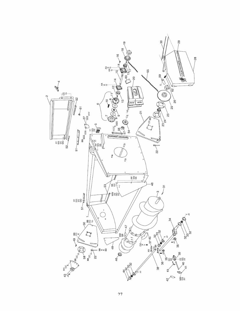
________________________________________________________________________ PART REF NUMBER DESCRIPTION QTY ________________________________________________________________________________ 1 PU19100 Table Frame ............................................................................ 1 2 PU19101 Adaptor - Case ............................................. Nominate Model 1 PU19102 Adaptor - John Deere ................................... Nominate Model 1 PU19103 Adaptor - New Holland ................................. Nominate Model 1 PU19104 Adaptor - Gleaner ......................................... Nominate Model 1 PU19105 Adaptor - Massey Ferguson ......................... Nominate Model 1 PU19106 Adaptor - Claas ............................................. Nominate Model 1 PU19107 Adaptor - Deutz ............................................ Nominate Model 1 Note: Other makes nominate make and model 3 PU19108 Auger ....................................................................................... 1 4 PU19109 PTO Holder .................................. Nominate Make and Model 1 5 PU19110 Hose Support Assy .................................................................. 3 6 PU19111 Clutch Assy .............................................................................. 1 7 PU19112 Clutch Friction Plate ................................................................ 1 8 PU19113 Clutch Lining ............................................................................ 2 9 PU19114 Clutch 6 Splined Friction Plate ................................................ 1 10 PU19115 Clutch Spring and Bolt Assy (use 4) ........................................ 4 11 PU19116 Clutch Base Plate .................................................................... 1 12 PU19117 Key, 3/8” x 3/8” x 1.5”L (38mm) ............................................... 1 13 PU19118 Bearing 1 3/8” L/C Greasable .................................................. 2 14 PU19119 Housing 4 Bolt Holes ............................................................... 2 15 PU19120 Lay Shaft ................................................................................. 1 16 PU19121 Grease Nipple .......................................................................... 2 17 PU19122 Key, 3/8” x 5/16” x 1.5” (38mm) ............................................... 1 18 PU19123 Sprocket, Cone Loc 3/4”P x 16T ............................................. 1 19 PU19124 Cone, Sprocket ........................................................................ 1 20 PU19125 Mount Assy, Lay Shaft ............................................................. 1 21 PU19126 Mount Assy, Auger L/H ............................................................ 1 22 PU19127 Adjuster ................................................................................... 2 23 PU19128 Flange Plate ............................................................................ 2 24 PU19129 Bearing 1 1/2” L/C Non Greasable .......................................... 1 25 PU19130 Sprocket, 3/4”P x 57T, Cone Loc ............................................ 1 26 PU19131 Cone, Sprocket ........................................................................ 1 27 PU19132 Guard Latch ............................................................................. 1 28 PU19133 Guard ....................................................................................... 1 29 PU19134 Decal - Side Panel ................................................................... 1 30 PU19135 Decal - Back Panel .................................................................. 1 31 PU19136 Key, 3/8” x 5/16” x 2.4” long (60mm) ....................................... 1 32 PU19137 Flange ...................................................................................... 6 33 PU19138 Bearing 1 3/8” L/C Non Greasable .......................................... 3 34 PU19139 Crank Shaft .............................................................................. 1 35 PU19140 Collar Retainer ......................................................................... 2 36 PU19141 Clamp Block Crank Shaft ........................................................ 1 37 PU19142 Clamp Plate Crank Shaft ......................................................... 1

29
PICK-UP TABLE SERIAL NUMBER FROM PUT99001
________________________________________________________________________ PART REF NUMBER DESCRIPTION QTY ________________________________________________________________________ 38 PU19143 Shaft, Crank Shaft Assy ......................................................... 1 39 PU19144 Bearing Nylon, Retractable Finger ......................... as required 40 PU19145 Finger Retractable ................................................... as required 41 PU19146 Bush Nylon, Retractable Finger..............................as required 42 PU19147 Cover Plate, Retractable Finger..............................as required 43 PU19148 Adjuster Plate, Retractable Finger..........................................1 44 PU19149 Key, 3/8” x 3/8” x 1.25” (32mm) ............................................... 1 45 PU19150 Flight Extension L/H .................................................. if required PU19151 Flight Extension R/H .................................................. if required 46 PU19152 Spacer, 1 3/8” 1.D. x 1/2” w (12mm wide) ............................... 1 47 PU19153 Cover ....................................................................................... 2 48 PU19154 Cover Side Panel ..................................................................... 2 49 PU19155 Grease Nipple .......................................................................... 1 50 PU19156 Mount Assy, Auger R/H .......................................................... 1 51 PU19158 Cut Off Plate, Table ................................................................. 2 52 PU19159 Cut Off Plate Adaptor .............................................................. 2 53 PU19160 Cut Off Table Floor, short 1220mm ........... Canola, Lupins 2 PU19165 Cut Off Table Floor, long 1450mm ................. Canola, Lupins 2 PU19168 Cut Off Table Floor, short . Barley (not shown) recommended 2 PU19169 Cut Off Table Floor, long .. Barley (not shown) recommended 2 54 PU19161 Sprocket Idler 3/4” x 15T ......................................................... 1 55 PU19162 Chain, 3/4” P x 112 Link + Con + Crank .................................. 1 56 PU19163 TAB Nut, 1/2” UNC .................................................................. 1 57 PU19164 Spacer 5000 x 1610 x 19w ...................................................... 1 58 PU19166 Flange Hub .............................................................................. 1 59 PU19167 Guard Stay .............................................................................. 1 60 PU19176 Bearing Slide Lock ................................................................... 1 61 PU19177 Key Guard Holder .................................................................... 1 62 PU19178 Guard Stay Spring ................................................................... 1 63 PU19179 Safety Bracket, Finger.............................................As required

30

31
PICK-UP FRONT SERIAL NUMBER FROM PUT99001
________________________________________________________________________ PART REF NUMBER DESCRIPTION QTY ________________________________________________________________________ 1 PU19001 Castor Arm .............................................................................. 2 2 PU19003 Fibre Pad ................................................................................ 2 3 PU19004 Grease Nipple ......................................................................... 2 4 PU19005 Clamp Plate Stubble Guard .................................................... 4 5 PU19006 Stubble Guard ......................................................................... 2 6 PU19007 Wiper - stubble ....................................................................... 2 7 PU19008 Axle assy. ................................................................................ 2 8 PU19009 Bush ........................................................................................ 4 9 PU19010 Seal ......................................................................................... 4 10 PU19011 Bearing Timkin Roller Set ........................................................ 4 12 PU19013 Rim .......................................................................................... 2 13 PU19014 Tyre 18.5 x 9.5 x 6 Ply ............................................................ 2 14 PU19015 Flutter Control ......................................................................... 2 15 PU19016 Wheel Arm Mount - L/H .......................................................... 1 PU19017 Wheel Arm Mount - R/H .......................................................... 1 16 PU19018 Spacer 50mm .......................................................................... 2 17 PU19019 Spacer 30mm .......................................................................... 2 18 PU19020 Spacer 15mm .......................................................................... 2 19 PU19021 Washer .................................................................................... 4 21 PU19023 Lynch Pin ................................................................................. 2 22 PU19024 Support Arm - L/H ................................................................... 1 PU19025 Support Arm - R/H ................................................................... 1 23 PU19026 Wheel Arm - L/H ...................................................................... 1 PU19027 Wheel Arm - R/H ..................................................................... 1 24 PU19028 End Cheek - L/H ...................................................................... 1 PU19029 End Cheek - R/H ..................................................................... 1 25 PU19030 Roller, Plain ............................................................................ 2 26 PU19031 Cross Members ....................................................................... 2 27 PU19032 Roller, Small Segregated ......................................................... 1 28 PU19033 Roller, Large Segregated ........................................................ 1 29 PU19034 Draper Belt Front Punched ...................................................... 8 PU19035 Draper Belt with Tines ............................................................. 8 30 PU19036 Tines ....................................................................... (per belt) 78 31 PU19037 Draper, Rear, Plain with Slats ................................................. 8 32 PU19038 Joiner Set, Bolt, Washer, Nut ................................... (per belt) 1 33 PU19039 Nut, Tine, Bolt .......................................................... as required 34 PU19040 Bolt, Tine ................................................................. as required 35 PU19041 Sprocket c/w Bearing ............................................................... 2 36 PU19042 Bush 30mm ............................................................................. 1 37 PU19043 Tensioner Mount ..................................................................... 1 38 PU19044 Chain, 5/8” P x 77 + 1 x 1/2 Link & Con .................................. 1 39 PU19045 Grease Nipple ......................................................................... 8 40 PU19046 Bearing Housing ...................................................................... 8 41 PU19047 Key 5/16” x 1 1/2” .................................................................... 5

32
PICK-UP FRONT SERIAL NUMBER FROM PUT99001
________________________________________________________________________ PART REF NUMBER DESCRIPTION QTY ________________________________________________________________________ 42 PU19048 Plate Adjuster ......................................................................... 4 43 PU19049 Plate Adjuster ......................................................................... 4 44 PU19050 Sprocket, Cone-Loc 5/8” P x 14T ............................................ 4 46 PU19052 Chain Adjuster ......................................................................... 1 47 PU19053 Tensioner Assy. ....................................................................... 1 48 PU19054 Sprocket Cone-Loc 5/8” P x 18T ............................................. 1 49 PU19055 Chain 5/8 P x 105 Links + Crank + Joiner ............................... 1 50 PU19056 Coupler Motor .......................................................................... 1 51 PU19057 Bush, Nylon ............................................................................. 1 52 PU19058 Torque Arm ............................................................................. 1 53 PU19059 Collar ....................................................................................... 2 54 PU19060 Spring 8mm ............................................................................. 2 55 PU19061 Spring Joiner Carrier Bush ...................................................... 2 56 PU19062 Crush Tube .............................................................................. 4 57 PU19063 Rod, Carrier ............................................................................. 2 58 PU19064 Motor, Hydraulic ...................................................................... 1 59 PU19065 Key 1/4” x 1/4” x 1” .................................................................. 1 60 PU19066 Key 1/4” x 1/4” x 2” .................................................................. 1 61 PU19067 Nipples 7/8 UN O ring x 1/2” BSP ........................................... 2 62 PU19068 Hydraulic Hose, 1/2” ....... length depending on header make 1 63 PU19069 Hydraulic Hose, 1/2” ....... length depending on header make 1 64 PU19070 Female Coupler (Not for Gleaner) ........................................... 1 65 PU19071 Male Coupler (Not for Gleaner) ............................................... 1 66 PU19072 Gleaner Coupler, Male R Series ............................................. 1 67 PU19073 Gleaner Coupler, Female R Series ........................................ 1 68 PU19074 Tyre Repair Kit ......................................................................... 1 69 PU19097 Spacer 15mm .......................................................................... 1 70 PU19099 Bearing 1 1/4” L/C Greasable .................................................. 8 71 PU19170 Seal Kit Hydraulic Motor .......................................................... 1 72 PU19171 Bush ........................................................................................ 1 73 PU19172 Bush ........................................................................................ 1 74 PU19173 Spring 10mm ........................................................................... 2 75 PU19174 Spring Carrier Bush ................................................................. 2 76 PU19175 Rod Carrier Bush ..................................................................... 1

33

34
PICK-UP FRONT SERIAL NUMBER FROM PUT99001
________________________________________________________________________ PART REF NUMBER DESCRIPTION QTY ________________________________________________________________________ 1 PU19075 Deflector Front - L/H ............................................................... 1 PU19076 Deflector Front - R/H ............................................................... 1 2 PU19077 Deflector Rear - L/H ................................................................. 1 PU19078 Deflector Rear - R/H ............................................................... 1 3 PU19079 Fender - L/H ............................................................................ 1 PU19080 Fender - R/H ........................................................................... 1 4 PU19081 Nose - L/H .............................................................................. 1 PU19082 Nose - R/H ............................................................................... 1 5 PU19083 Cover, Front - L/H .................................................................... 1 PU19084 Cover, Front - R/H .................................................................. 1 6 PU19085 Guard Key .............................................................................. 1 7 PU19086 Cover, Rear - L/H ................................................................... 1 PU19087 Cover, Rear - R/H .................................................................... 1 8 PU19088 Side Panel - L/H ..................................................................... 1 PU19089 Side Panel - R/H ...................................................................... 1 9 PU19090 Hinge ....................................................................................... 2 10 PU19091 Pin Hinge ................................................................................. 2 11 PU19092 Hinge - L/H .............................................................................. 1 12 PU19093 Split Pin ................................................................................... 2 13 PU19094 Frame Wind Guard .................................................................. 1 14 PU19095 Tine - Wind Guard ................................................................. 22 15 PU19096 Retainer Plate Tine ................................................................ 22 16 PU19098 Hinge - R/H .............................................................................. 1

35
BOLT LIST SERIAL NUMBER FROM PUT99001
________________________________________________________________________ PART REF NUMBER DESCRIPTION ________________________________________________________________________ A Nut, Nyloc 3/4” UNC B Nut, Hex Head 5/8” UNC C Washer, Spring 5/8” D Washer, Flat 5/8” E Bolt, Hex Head 5/8” x 2 3/4” UNC F Bolt, Hex Head 1/4” x 3/4” UNC G Nut, Nyloc 1/2” UNC H Nut, Wizzloc 1/4” UNC I Bolt, Hex Head 1/2” x 2” UNC J Nut, Wizzloc 1/2” UNC K Washer, Flat 1/2” grade 8 L Bolt, Hex Head 1/2” x 1 1/2” UNC M Bolt, Hex Head 3/8” x 3/4” UNC N Bolt, Hex Head 3/8” x 1” UNC O Nut, Wizzloc 3/8” UNC P Washer, Flat 3/8” Q Bolt, Cup Head 3/8” x 3/4” UNC R Bolt, Cup Head 1/2” x 1 1/2” UNC S Bolt, Hex Head 5/8” x 2” UNC T All Thread 3/8” UNC 4” long U Bolt, Hex Head 3/8” x 1 3/4” UNC V Bolt, Hex Head 5/8” x 2 1/4” UNC W Bolt, Cup Head 7/16” x 1 1/2” UNC X Bolt, Hex Head 3/8” x 2” UNC Y Washer, Spring 3/8” Z Bolt, Hex Head 1/2” x 5” UNC AA Bolt, Hex Head 1/2” x 1 3/4” UNC BB Nut, Hex 1/2” UNC CC Washer, Spring 1/2” DD Bolt, Hex Head, Stainless 5/16” x 2” UNC EE Washer, Flat 5/16” FF Nut, Hex 5/16” UNC GG Washer, Spring 5/16” HH Bolt, Hex Head, 1/2” x 1” UNC II Set Screw, 3/8” x 1” UNC JJ Nut, Hex 3/8” UNC KK Bolt, Hex Head, 1/2” x 3 1/2” UNC LL Washer, Flat 1/2” MM Bolt, Button Head 5/16” x 3/4” UNC (3/16” Allan Key Head) NN Washer, Shakeproof 5/16” OO Bolt, Cup Head, 3/8” x 1” UNC PP Bolt, Hex Head 5/16” x 2” UNC QQ Bolt, Cup Head 5/16” x 1” UNC RR Bolt, Cup Head 7/16” x 1 3/4” UNC SS Bolt, Hex Head 5/16” x 2 1/4” UNC

36
BOLT LIST SERIAL NUMBER FROM PUT99001
________________________________________________________________________ PART REF NUMBER DESCRIPTION ________________________________________________________________________ TT Bolt, Hex Head 5/16” x 1” UNC UU Nut, Wizzloc 5/16” VV Washer, Flat 5/16” grade 8 WW Bolt, Cup Head 5/16” x 3/4” UNC XX Bolt, Hex Head 1/2” x 2 1/4” UNC YY Nut, Nyloc 7/16” UNC ZZ Nut, Hex 7/16” UNC AAA Washer, Spring 7/16” BBB Bolt, Hex Head 5/8” x 1 1/2” UNC CCC Washer, Flat 5/8” grade 8 DDD Bolt, Hex Head 5/8” x 1 1/4” UNC EEE Washer, Belleville ss FFF Bolt, Hex Head 1/2” x 1 1/4” UNC GGG Nut Nyloc 5/16”