draft - indiaenvironmentportal.org.in national energy conservation centre (enercon) pakistan...
TRANSCRIPT

-1-
DRAFT
NATIONAL ENERGY CONSERVATION CENTRE (ENERCON)
PAKISTAN ENGINEERING COUNCIL (PEC)
2011

-2-
PREFACE
Introduction
Pakistan is facing a huge energy shortfall. On one hand, this has led to extended black-outs and brown-outs, and on the other it has made energy a very expensive commodity. It is therefore imperative to design better systems that minimize energy consumption and improve efficiency. Energy provisions in Pakistan Building Code 1986 need to be comprehensively bolstered, so that safety and economic health of communities is protected. This has been encapsulated in these "Energy Provisions-2011" as an integral part of Pakistan Building Code 1986. The thrust of these Provisions is to provide energy efficiency benchmarks for buildings. Energy Provisions are compatible with relevant standards of ASHRAE, ANSI, ARI, ASTM etc. Revision to these Provisions will be done every three years i.e. if not required earlier, so that they are debated upon and kept continuously relevant.
Development Government of Pakistan has mandated ENERCON to act as the national coordinator for Energy Conservation measures and policy. In this regard ENERCON approached Pakistan Engineering Council for developing Building Code of Pakistan (Energy Provision-2011). Pakistan Engineering Council, being the statutory body for the development of building codes, constituted a task force for said code development. The implementation and enforcement of this Code vests with Ministry of Housing and Works, through concerned authorities. These Provisions focus on high-end domestic and commercial consumers, and are designed to conserve energy without compromising public safety. Every effort has been made to ensure that these Provisions do not unnecessarily increase cost, or restrict use of new materials and technology. The future development of Energy Provisions-2011 shall encompass other consumers also. Adoption
The Energy Provisions shall be adopted as an integral part of Building Code of Pakistan 1986. The notification (SRO) for adoption must give general legal cover to the Code, for enforcement. Such notification shall also allow changes to be made after a minimum of three years, and a maximum of five years by Pakistan Engineering Council.
Maintenance
The Energy Provisions-2011 of the Code shall be kept updated by a Standing Committee working under the aegis of Pakistan Engineering Council. This Committee

-3-
will interact with representatives of industry, engineering professionals and other stakeholders in an open code development process before any change is suggested.
Waiver
While utmost care was taken by the members who contributed in developing these provisions of the code, however the individuals concerned, and/or their respective organizations, accept no liability resulting from the compliance, or non-compliance of the said provisions by practitioners. The power to ensure compliance vests only with the Government of Pakistan.

-4-
ACKNOWLEDGEMENTS A document as important and detailed as this Code has input from many individuals.
While it is not possible to acknowledge everyone’s effort here, it is important to list those
in the PEC Task Force for Development of Building Energy Code of Pakistan;
1. Engr. Syed Imtiaz Hussain Gilani (Convenor) Vice Chancellor University of Engineering and Technology, Peshawar
2. Mr Faridullah Khan
Managing Director ENERCON Ministry of Environment, Islamabad
3. Prof. Engr. Dr. Muzzaffar Mahmood Pro Vice Chancellor 1, NED University of Engineering and Technology, Karachi
4. Prof. Engr. Dr. Sarosh H. Lodi
Dean, Faculty of Civil Engineering and Architecture NED University of Engineering and Technology, Karachi
5. Engr. Muhammad Khalid
Director General, EM&C PEPCO, Lahore
6. Ar. Shama Usman Chairperson, PCATP, Islamabad
7. Engr. Farhan A. Mehboob Ex-President, ASHRAE Pakistan Chapter, Karachi
8. Engr Dr Javed Yunus Uppal Chief Executive, EPDC, Lahore
9. Mr. Muhammad Irfan Deputy Director General, M/o Housing & Works, Islamabad
10. Engr. Tafseer Ahmed Khan
Director, PSQCA, Karachi
11. Engr Faiz M. Bhutta M/s Izhar Construction (Pvt) Ltd, Lahore

-5-
12. Engr. Khurram Khaliq Khan
PEC Task Leader, Fire Safety Provisions, Rawalpindi
13. Engr. Farida Javed Consultant (Ex-Principal) Polytechnic Institute for Women Islamabad
14. Engr. Abrar Hussain Shah
Director General E&M, CDA, Islamabad
15. Engr Nasir J.R. Sheikh Advocate
16. Engr Dr Mohammad Irfan Mufti
UET, Peshawar
17. Engr Muhammad Zaman Consultant/ Ex-Director General CDA, Islamabad
18. Dr.Muhammad Sultan Khan
Associate Professor, GIKI, Topi
19. Engr M. Noman Ali M/o Housing and Works, Islamabad
20. Engr. Akram Rashid
Assistant Professor Air University, Islamabad
21. Engr Z.M. Peracha
Registrar, Pakistan Engineering Council
22. Engr Dr Ashfaq Ahmed Sheikh Addl Registrar, Pakistan Engineering Council
23. Engr Muhammad Abrar Malik,
Assistant Chief, ENERCON, Islamabad

-6-
SOURCE DOCUMENTS
Ministry of Housing and Works, Government of Pakistan, acknowledges that it has the permission of the American Society of Heating, Refrigeration and Airconditioning Engineers (ASHRAE) to transcribe and reproduce portions of ASHRAE Standard 90.1-2004 for the purpose of the Energy Provisions-2011. The Ministry of Housing and Works, Government of Pakistan accepts that ASHRAE have the ownership and copyrights of all transcribes and reproduce portions from their document used in the energy Provisions 2011. The only exception is Section-4 Building Envelope, which has been developed keeping in view Energy Codes of regional countries and 0 local environment.

-7-
TABLE OF CONTENTS
PREFACE ACKNOWLEDGEMENT SOURCE DOCUMENTS
SECTION – 1 PURPOSE SECTION – 2 SCOPE 2.0 Title 2.1 Scope 2.2 Applicable Building Systems 2.3 Exemptions 2.4 Limitation SECTION – 3 ADMINISTRATION & ENFORCEMENT 3.0 Administration and Enforcement and Enforcement 3.1 Compliance Requirements 3.1.1 Mandatory Requirements 3.1.2 New Buildings 3.1.3 Alterations to Existing Buildings 3.1.3.1 Building Envelope 3.1.3.2 Heating, Ventilation and Air Conditioning 3.1.3.3 Service Water Heating
3.1.3.4 Lighting 3.1.3.5 Electric Power System and Motors 3.2 Administrative Requirements 3.3 Compliance Documents 3.4 Supplementary Information SECTION – 4 BUILDING ENVELOPE 4.1 General 4.2 Mandatory Requirements
4.2.1 Building Envelope 4.2.1.1 External Walls and Roofs 4.2.1.2 Glass and Framing System 4.2.1.3 Air Leakage/ Infiltration

-8-
4.3 Compliance Documents SECTION – 5 HEATING, VENTILATING AND AIR CONDITIONING
5.1 General 5.2 Mandatory Requirements 5.2.1 Controls 5.2.1.1 System Controls 5.2.1.2 Temperature Control 5.2.1.3 Dead Band 5.2.1.4 Mechanical Ventilation 5.2.1.5 Non- Residential Kitchen Space 5.2.1.6 Cooling Towers 5.2.2 Piping and Ductwork 5.2.3 System Balancing 5.2.3.1 General 5.2.3.2 Air System Balancing 5.2.3.3 Hydronic System Balancing 5.2.4 Condenser 5.2.4.1 Condenser Location 5.2.4.2 Treated Water for Condenser 5.3 Recommended Guidelines 5.3.1 Minimum Equipment Efficiencies 5.3.2 Recommended Requirements 5.3.2.1 Economizers 5.3.2.1.1 Air Side Economizer 5.3.2.1.2 Testing Air Side Economizers 5.3.2.2 Hydronic Variable Flow Systems 5.4 Recommended Voluntary Adoption 5.4.1 Natural Ventilation 5.4.2 Alternate Energy 5.5 Compliance Documentation
SECTION – 6 SERVICE WATER HEATING 6.1 General 6.2 Mandatory Requirements 6.2.1 Piping Insulation 6.2.2 Equipment Efficiency 6.2.3 Swimming Pools 6.2.3.1 Pool Covers 6.2.3.2 Pool Heaters

-9-
6.3 Volunteer Adoption 6.4 Compliance Documentation SECTION – 7 LIGHTING 7. Lighting 7.1 General 7.2 Mandatory Requirements 7.2.1 Lighting Control 7.2.1.1 Interior Space Control 7.2.1.2 Exterior Lighting Control 7.2.1.3 Additional Control 7.2.2 Exit Signs 7.2.3 Exterior Building Grounds Lighting 7.2.4 Landscape Lighting 7.3 Interior Lighting Power 7.3.1 Building Area Method 7.3.2 Space by Space Method 7.3.3 Installed Interior Lighting Power 7.4 Exterior Lighting Power 7.5 Recommended Voluntary Adoption 7.5.1 Lighting Control 7.5.1.1 Automatic Lighting Shutoff 7.5.1.2 Control in Day Lighted Areas 7.5.1.3. Energy Efficient Lighting 7.5.1.4 Energy Saving Systems 7.5.1.5 Alternate Energy: 7.6 Compliance Documentation
SECTION – 8 ELECTRICAL POWER 8. Electrical Power 8.1 General
8.2 Mandatory Requirements 8.2.1 Transformers 8.2.1.1 Maximum Allowable Power Transformer Losses 8.2.1.2 Measurement and Reporting of Transformer Losses 8.2.2 Energy Efficient Motors 8.2.3 Power Factor Correction 8.2.4 Check-Metering 8.2.5 Power Distribution Systems 8.2.5.1 Power Distribution System Losses 8.3 Compliance Documentation SECTION – 9 Definitions, Abbreviations & Acronyms

-10-

-11-
LIST OF TABLES
TABLE 4.2.1.1: External Walls and Roof
TABLE 4.2.1.2A: External Glass Area (≤40% )
TABLE 4.2.1.2B: External Glass Area (>40%)
Table 5.2.2A: Minimum Pipe Insulation Thickness
Table 5.2.2B: Minimum Duct Insulation R-Value , Combined Heating and Cooling
Supply Ducts and Return Ducts
TABLE 5.3.1 A: Air Conditioners and Condensing Units
TABLE 5.3.1B: Electrically Operated Unitary and Applied Heat Pumps Minimum
Efficiency Requirements
TABLE 5.3.1C: Water Chilling Packages Minimum Efficiency Requirements
TABLE 5.3.1D: Electrically Operated Packaged Terminal Air Conditioners, Packaged
Terminal Heat Pumps, Single-Package Vertical Air Conditioners,
Single -Package Vertical Heat Pumps, Room Air Conditioners, and
Room Air Conditioner Heat Pumps-Minimum Efficiency Requirements
TABLE 5.3.1E: Warm Air Furnaces and Combination Warm Air Furnaces/Air-
Conditioning Units, Warm Air Duct Furnaces and Unit Heaters
TABLE 5.3.1F: Gas and Oil Fired Boilers-Minimum Efficiency Requirements
TABLE 5.3.1G: Performance Requirements for Heat Rejection Equipment
TABLE 6.2.1: Minimum Pipe Insulation Thickness
TABLE 6.2.2: Performance Requirements for Water Heating Equipment
TABLE 7.3.1: Interior Lighting Power Densities Building Area Method
TABLE 7.3.2: Interior Lighting Power Densities– Space by Space Method Space
Function LPD (W/ft2)
TABLE 7.4: Exterior Building Lighting Power
TABLE 8.2.1.1: Maximum Allowable Losses of 11 kV Transformers

-12-
TABLE 8.2.2: Minimum Acceptable Motor Efficiencies

-13-
SECTION – 1
1. PURPOSE
The purpose of Energy Provisions-2011 is to provide minimum
requirements for energy-efficient design and construction of buildings. In
the current scenario, energy has become a defining factor in the progress
of nations. For Pakistan, it is absolutely imperative that we improve energy
efficiency in buildings by incorporating international best practices
appropriate to our environment, coupled with traditional materials,
technologies and craftsmanship developed indigenously over a very long
time.
While sustainable alternate energy sources must be developed and
harnessed, it is more important that we use existing energy resources in a
more efficient way.

-14-
SECTION – 2 2.0 TITLE
This Code shall be known as the Building Code of Pakistan- Energy Provisions 2011 hereinafter referred to as the “Energy Provisions 2011”.
2.1 Scope These Energy Provisions shall apply to buildings and building clusters that
have: a total connected load of 100 kW or greater, or a contract demand of 125 kVA, or a conditioned area of 900 m2 or unconditioned buildings of covered area of 1200 m2 or more.
The scope of the Energy Provisions is applicable to the following to provide
minimum energy-efficient requirements for the design and construction of: 1) new buildings and their systems
2) new portions of existing buildings and their systems, if the
conditioned area or connected load exceeds the prescribed above 3) new systems and new equipment in existing buildings, 4) increase in the electricity load beyond the limit mentioned above and 2.2 Applicable Building Systems The Energy Provisions shall apply to the following: (a) building envelopes, (b) building mechanical systems and equipment, including heating,
ventilation, and air conditioning (HVAC), (c) service water heating, (d) lighting, and (e) electrical power and motors. 2.3 Exemptions The Energy Provisions shall not apply to the following:

-15-
(a) buildings that do not use either electricity or fossil fuel, (b) Government notified historically significant and heritage buildings,
(c) equipment and portions of building systems that use energy only for
manufacturing processes. 2.4 Limitation
In case of any conflict, relevant Provisions of Safety, Health, or Environmental Codes shall prevail.

-16-
SECTION – 3
3.0 Administration and Enforcement 3. Administration and Enforcement 3.1 Compliance Requirements Review and approval of plans and specifications by respective sanctioning
and development authorities/ municipalities shall be in accordance with Energy Provisions 2011.
3.1.1 Mandatory Requirements
Compliance with the requirements of the Energy Provisions 2011 shall be mandatory for all applicable buildings mentioned in Section - 2.
3.1.2 New Buildings
New buildings shall comply with the provisions of Sections 4 to 8. 3.1.3 Alterations to Existing Buildings: Alterations to existing buildings and building systems shall comply with the
Energy Provisions 2011 of Sections 4.0 through Section 8.0. 3.1.3.1 Building Envelope
Alterations to the building envelope shall comply with the requirements of Section – 4.
3.1.3.2 Heating, Ventilation and Air Conditioning
Alterations to building heating, ventilation and air conditioning equipment or systems shall comply with the requirements of Section- 5, applicable to the portions of the building and its systems being altered. Any new equipment or control devices/systems installed in conjunction with the alteration shall comply with the specific minimum efficiency requirements applicable to that equipment or control device/system provided herein…...
3.1.3.3 Service Water Heating
Alterations to building service water heating equipment or systems shall comply with the requirements of Section – 6, applicable to the portion of the building and its system being altered. Any new equipment or control devices/system installed in conjunction with the alteration shall comply with

-17-
the specific minimum efficiency requirements applicable to that equipment or system/control device provided herein…...
3.1.3.4 Lighting
Alterations to building lighting equipment or systems shall comply with the lighting power density requirements of Section – 7, applicable to the portion/s of the building and its system being altered. Any new equipment or system/control devices installed in conjunction with the alteration shall with comply the specific requirements applicable to that equipment or system/control device provided herein…...
3.1.3.5 Electric Power System and Motors
Alterations to building electric power systems and motor shall comply with the requirements of Section – 8, applicable to the portions of the building and its systems being altered. Any new equipment or control devices installed in conjunction with the alteration shall comply with the specific requirements applicable to that equipment or control device.
3.2 Administrative Requirements Administrative requirements relating to permit requirements, having
jurisdiction, energy standards, interpretations, claims of exemptions, and rights of appeal are specified by the authority having jurisdiction.
3.3 Compliance Documents
Compliance documents shall show all pertinent data and features of the building, equipment, and systems in sufficient detail to permit the authority having jurisdiction to verify that the building complies with the Energy Provisions 2011.
3.4 Supplementary Information
The authority having jurisdiction may require supplementary information necessary to verify compliance with these Provisions, such as calculations, worksheets, compliance forms, manufacturer’s literature, or other data.

-18-
SECTION – 4 4. BUILDING ENVELOPE 4.1 General
The criteria set in this section establish the minimum energy conservation and efficiency requirements for the building envelope. Design criteria that results in greater levels of energy efficiency and conservation shall be allowed. The building envelope shall comply with the mandatory provisions of this Section.
4.2 Mandatory Requirements 4.2.1 Building Envelope
The design of buildings, and selection of materials forming their surfaces, shall aim at reducing heat transfer to and from buildings and adhere to the following criteria.
4.2.1.1 External Walls and Roofs Overall U values of external walls and roofs shall not exceed limits specified in Table 4.2.1.1.
TABLE 4.2.1.1: External Walls and Roof
Wall U: 0.57 W/m2.K (0.100 Btu/h.ft2. oF) Roof U: 0.44 W/m2.K (0.078 Btu/h.ft2. oF)
4.2.1.2 Glass and Framing System
a) For buildings with external glass area, not exceeding 40% of the external wall area of the building, the overall U values and shading coefficient shall not exceed limits specified in Table 4.2.1.2A.
TABLE 4.2.1.2A: External Glass Area (≤40% )
Heat Transmission Coefficient (U): 3.5 W/m2.K (0.44 Btu/h.ft2. oF) Shading Coefficient (SC): 0.76
b) For buildings with external glass area, in excess of 40% of the
external wall area of the building, the overall U values and shading coefficient shall not exceed limits specified in Table 4.2.1.2B.

-19-
TABLE 4.2.1.2B: External Glass Area (>40%) Heat Transmission Coefficient (U): 2.5 W/m2.K (0.37 Btu/h.ft2. oF) Shading Coefficient (SC): 0.35
4.2.1.4 Air Leakage/ Infiltration
The building envelope shall be durably sealed, caulked, gasketed, or weather-stripped to minimize air leakages wherever the tendency exits.
Vestibules/ lounges/ entrances shall be provided to minimize infiltration through revolving/ sliding/ swinging doors. Air leakages for revolving/ sliding/ swinging entrance/ exit doors shall not exceed 5.0 L/s/m2 (1.0 cfm/ft2) and for windows, doors air leakage shall not exceed 2.0 L/s/m2 (0.4 cfm/ft2).
4.3 Compliance Documentation
The authority having jurisdiction would develop the required documents for implementation.

-20-
SECTION – 5
5.0 HEATING, VENTILATING AND AIR CONDITIONING 5.1 General All heating, ventilating and air-conditioning shall comply with the mandatory
Provisions of this Section. 5.2 Mandatory Requirements 5.2.1 Controls 5.2.1.1 System Control
All mechanical cooling and heating systems shall be controlled by a building management system or a time clock that:
a) Can start and stop the system under different schedules for three
different day types per week, b) is capable of retaining programming and time setting during a loss of
power for a period of at least 10 hours, and (c) Includes an accessible manual override that allows temporary
operation of the system for up to 2 hours. Exceptions to 5.2.1.1: (a) Residential sector with non centralized system/s 5.2.1.2 Temperature Control
Temperature to be maintained as follows:
Summer: not less than 25oC Winter: not more than 22oC 5.2.1.3 Dead Band
All heating and cooling equipment shall be temperature controlled. Where a unit provides both heating and cooling, controls shall be capable of providing a temperature dead band of 3°C (5°F) within which the supply of heating and cooling energy to the zone is shut off or reduced to a minimum. Where separate heating and cooling equipment serve the same

-21-
temperature zone, thermostats shall be interlocked to prevent simultaneous heating and cooling.
Exceptions to 5.2.1.3:
a) Thermostats that require manual changeover between heating and cooling modes.
b) Special occupancy or special applications where wide temperature
ranges are not acceptable (such as retirement homes, process applications, data processing, museums, some areas of hospitals) and are approved by the authority having jurisdiction.
5.2.1.4 Mechanical Ventilation
Each mechanical ventilation system (supply and/or exhaust) shall be equipped with a readily accessible switch or other means for shut off or for volume reduction or shut off when full ventilation is not required. Automatic or gravity dampers that close when the system is not operating shall be provided for outdoor air intake and exhausts. Automatic or manual dampers installed for the purpose of shutting off ventilation systems shall be designed with tight shutoff characteristics to minimize air leakage.
Exceptions to 5.2.1.4 Manual dampers for outdoor intakes may be used in the following cases:
a) For single and multi family residential buildings. b) Dampers are not required when ventilation air flow is less than 100
ft³/ min (0.047 m³/ s). 5.2.1.5 Non- Residential Kitchen Space
Non-residential kitchen space shall be designed with an exhaust air and make up air balance such that the space is never under a positive pressure with reference to adjacent space.
5.2.1.6 Cooling Towers All cooling towers and closed circuit fluid coolers shall have preferably
variable drives either two speed motors / pony motors, controlling the fans.

-22-
5.2.2 Piping and Ductwork
(a) Piping shall be insulated in accordance with table 5.2.2A:
Table 5.2.2A*
Minimum Pipe Insulation Thickness a
Insulation Conductivity Nominal Pipe or Tube Size
(In.) Fluid Design Operation
Temp. Range (ºF)
Conductivity Btu. in./
(h.ft2.ºF)
Mean Rating
Temp. ºF <1
1 to < 1-1/2
1-1/2 to <4
4 to < 8 > 8
Heating Systems (Steam, Steam Condensate, and Hot Water) b, c > 350 0.32 - 0.34 250 2.5 3.0 3.0 4.0 4.0
251 – 350 0.29 – 0.32 200 1.5 2.5 3.0 3.0 3.0 201 – 250 0.27 – 0.30 150 1.5 1.5 2.0 2.0 2.0 141 – 200 0.25 – 0.29 125 1.0 1.0 1.0 1.5 1.5 105 – 140 0.22 – 0.28 100 0.5 0.5 1.0 1.0 1.0
Domestic and Service Hot Water Systems 105+ 0.22 – 0.28 100 0.5 0.5 1.0 1.0 1.0
Cooling Systems (Chilled Water, Brine, and Refrigerant)d 40 – 46 0.22 – 0.28 100 0.5 0.5 1.0 1.0 1.0
< 40 0.22 – 0.28 100 0.5 1.0 1.0 1.0 1.5
a For insulation outside the stated conductivity range, the minimum thickness (T) shall be determined as follows:
T = r {(1+ t/r)K/k – 1} Where T = minimum insulation thickness (in.), r = insulation thickness listed in this table for
applicable fluid temperature and pipe size, K = conductivity of alternate material at mean rating temperature (Btu in. [h ft2, 0F], and k = the upper value of the conductivity range listed in this table for the applicable fluid temperature.
b These thicknesses are based on energy efficiency consideration only. Additional insulation is
sometimes required relative to safety issues/surface temperature. c Piping insulation is not required between the control valve and coil on run-outs when the control
value is located within 4 ft of the coil and the pipe size is 1 in. or less. d These thicknesses are based on energy efficiency consideration only. Issues such as water
vapor permeability or surface condensation sometimes require vapor retarders or additional insulation.
Formatted: Font: 10 pt, ComplexScript Font: 10 pt
-23-
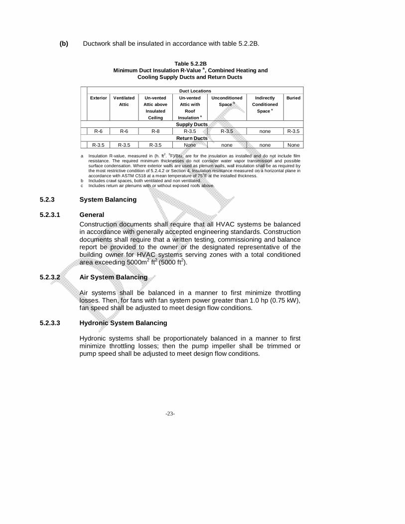
(b) Ductwork shall be insulated in accordance with table 5.2.2B.
Table 5.2.2B Minimum Duct Insulation R-Value a, Combined Heating and
Cooling Supply Ducts and Return Ducts
Duct Locations
Exterior Ventilated Attic
Un-vented Attic above Insulated Ceiling
Un-vented Attic with
Roof Insulation a
Unconditioned Space b
Indirectly Conditioned
Space e
Buried
Supply Ducts R-6 R-6 R-8 R-3.5 R-3.5 none R-3.5
Return Ducts R-3.5 R-3.5 R-3.5 None none none None
a Insulation R-value, measured in (h. ft2. 0F)/Btu, are for the insulation as installed and do not include film
resistance. The required minimum thicknesses do not consider water vapor transmission and possible surface condensation. Where exterior walls are used as plenum walls, wall insulation shall be as required by the most restrictive condition of 5.2.4.2 or Section 4, Insulation resistance measured on a horizontal plane in accordance with ASTM C518 at a mean temperature of 750F at the installed thickness.
b Includes crawl spaces, both ventilated and non ventilated. c Includes return air plenums with or without exposed roofs above.
5.2.3 System Balancing 5.2.3.1 General
Construction documents shall require that all HVAC systems be balanced in accordance with generally accepted engineering standards. Construction documents shall require that a written testing, commissioning and balance report be provided to the owner or the designated representative of the building owner for HVAC systems serving zones with a total conditioned area exceeding 5000m2 ft2 (5000 ft2).
5.2.3.2 Air System Balancing
Air systems shall be balanced in a manner to first minimize throttling losses. Then, for fans with fan system power greater than 1.0 hp (0.75 kW), fan speed shall be adjusted to meet design flow conditions.
5.2.3.3 Hydronic System Balancing
Hydronic systems shall be proportionately balanced in a manner to first minimize throttling losses; then the pump impeller shall be trimmed or pump speed shall be adjusted to meet design flow conditions.

-24-
Exceptions to 5.2.3.3: Impellers need not be trimmed nor pump speed adjusted:
(a) For pumps with pump motors of 10 hp or less, (b) When throttling results in no greater than 5% of the nameplate
horsepower draw, or 3 hp (2.24 kW), whichever is greater, above that required if the impeller was trimmed.
5.2.4 Condenser 5.2.4.1 Condenser Location
Care shall be exercised in locating the condenser in such a manner that heat sink is free of interference from heat discharge by devices located in adjoining spaces and also does not interfere with such other systems installed nearby.
5.2.4.2 Treated Water for Condenser
All buildings using centralized cooling water system shall use soft water for the condenser and chilled water system.
5.3 Recommended Guidelines 5.3.1 Minimum Equipment Efficiencies
HVAC Equipment shall meet or exceed the minimum performance at the specified rating conditions when tested in accordance with the specified test procedures. The Equipment shall satisfy all stated requirements unless otherwise stated.
TABLE 5.3.1 A Air Conditioners and Condensing Units
Equipment Type Size Category Heating
Section Type
Sub-Category or
Rating Condition
Minimum Efficiency a
Test Procedure b
Split System 12.0 SEER Air Conditioners,
Air Cooled <65,000 Btu/hc All Single Package 12.0 SEER
Split System 12.0 SEER Through-the- Wall,
Air Cooled ≤ 30,000 Btu/hc All Single Package 12.0 SEER
Small-Duct High-Velocity,
Air Cooled < 65,000 Btu/hc All Split System 10 SEER
ARI 210/240

-25-
Electric Resistance
(or None)
Split System and
Single Package 10.3 EER > 65,000 Btu/h
and < 135,000 Btu/h
All other Split System
and Single Package
10.1 EER
Electric Resistance (or None)
Split System and
Single Package 9.7 EER > 135,000 Btu/h
and < 240,000 Btu/h
All other Split System
and Single Package
9.5 EER
Electric
Resistance (or None)
Split System and
Single Package
9.5 EER 9.7 IPLV > 240,000 Btu/h
and < 760,000 Btu/h
All other Split System
and Single Package
9.3 EER 9.5 IPLV
Electric Resistance (or None)
Split System and
Single Package
9.2 EER 9.4 IPLV
Air Conditioners,
Air Cooled
> 760,000 Btu/h
All other Split System
and Single Package
9.0 EER 9.2 IPLV
ARI 340/360
Equipment Type Size Category Heating
Section Type
Sub-Category or
Rating Condition
Minimum Efficiency a
Test Procedure b
< 65,000 Btu/h All Split System and Single Package
12.1 EER
ARI 210/240
Electric Resistance (or None)
Split System and Single Package
11.5 EER
> 65,000 Btu/h and <135,000 Btu/h
All other Split System and Single Package
11.3 EER
Electric Resistance (or None)
Split System and Single Package
11.0 EER > 135,000 Btu/h
and <240,000 Btu/h
All other Split System and Single Package
10.8 EER
Electric Resistance (or None)
Split System and Single Package
1 1.0 EER 10.3 IPLV
Air Conditioners, Water
and Evaporatively Cooled
> 240,000 Btu/h
All other Split System and Single Package
10.8 EER 10.1 IPLV
ARI 340/360
Condensing Units, Air Cooled
> 135,000 Btu/h
10.1 EER 11.2 IPLV
ARI 365

-26-
Condensing Units, Water or
Evaporatively Cooled
> 135,000 Btu/h 13.1 EER 13.1 IPLV
a PLVs and part load rating conditions are only applicable to equipment with capacity modulation.
b ASHRAE 90.1-2004 contains a complete specification of the referenced test procedure,
including the referenced year version of the test procedure. c Single-phase, air-cooled air-conditioners < 65,000 Btu/h are regulated by NAECA. SEER
values are those set by NAECA.
TABLE 5.3.1B Electrically Operated Unitary and Applied Heat Pumps
Minimum Efficiency Requirements
Equipment Type Size Category Heating Section
Type
Sub-Category Or Rating Condition
Minimum Efficiency
a Test
Procedure b
Split System Single Package
12.0 SEER
ARI 210/240 Air Cooled
(Cooling Mode) <65,000 Btu/hc All 12.0
SEER
Split System 12.0 SEER Through the Wall (Air Cooled,
Cooling Mode)
<30,000 Btu/hc All Single Package 12.0
SEER
Small-Duct High- Velocity
(Air Cooled, Cooling Mode) < 65,000 Btu/hc All Split System 10 SEER
Electric Resistance (or None)
Split System and
Single Package 10.1 EER ARI
340/360 >65,000 Btu/h and
<135,000 Btu/h All other Split System
and Single Package
9.9EER
Electric Resistance (or None)
Split System and
Single Package 9.3 EER >135,000 Btu/h
and <240,000 Btu/h
All other Split System
and Single Package
9.1 EER
Electric Resistance (or None)
Split System and
Single Package
9.0 EER 9.2IPLV
Air Cooled (Cooling Mode)
>240,000 Btu/h
All other Split System
and Single Package
8.8 EER 9.0IPLV
<17,000Btu/h All 860F Entering Water 11.2 EER ISO-13256-1
> 17,000 Btu/h and
<65,000 Btu/h All 860F Entering
Water 12.0 EER ISO-13256-1 Water-Source (Cooling Mode)
>65,000 Btu/h and
< 135,000 Btu/h All 860F Entering
Water 12.0EER ISO-13256-1

-27-
Ground water-Source (Cooling Mode) <135,000 Btu/h All 590F Entering
Water 16.2 EER ISO-13256-1
Ground Source (Cooling Mode) < 135,000 Btu/h All 770FEntering
Water 13.4 EER ISO-13256-1
Split System 7.4 HSPF ARI 210/240 Air Cooled
(Heating Mode)
<65,000 Btu/hc (Cooling Capacity)
- Single Package 7.4 HSPF
Split System 7.4 HSPF Through the Wall (Air Cooled, Heating Mode)
<30,000 Btu/hc (Cooling capacity) -
Single Package 7.4 HSPF
Small-Duct High- Velocity
(Air Cooled, Heating Mode)
< 65,000 Btu/hc (Cooling capacity)
- Split System 6.8 HSPF ARI 210/240
47°F db/43°F wb
Outdoor air
3.2 COP ARI 340/360 >65,000 Btu/h
and <135,000 Btu/h
(Cooling Capacity)
- 17°F db/15°F
wb Outdoor air
2.2 COP
47°F db/43°F wb
Outdoor air
3.1 COP
Air Cooled (Heating Mode)
>135,000 Btu/h (Cooling Capacity)
- 17°F db/15°F
wb Outdoor air
2.0 COP
Water-Source (Heating Mode)
<135,000 Btu/h (Cooling Capacity)
- 68°F Entering Water 4.2 COP ISO-13256-1
Groundwater-Source (Heating Mode)
<135,000 Btu/h (Cooling Capacity)
- 50°F Entering Water 3.6 COP ISO-13256-1
Ground Source (Heating Mode)
< 135,000 Btu/h (Cooling Capacity)
- 32°F Entering Water 3.1 COP ISO-13256-1
a IPLVs and Part load rating conditions are only applicable to equipment with capacity
modulation. b ASHRAE 90.1-2004 contains a complete specification of the referenced test procedure,
including the referenced year version of the test procedure. c Single phase, air-cooled heat pumps < 65,000 Btu/h are regulated by NAECA, SEER and
HSPF values those set by NAECA.

-28-
TABLE 5.3.1C Water Chilling Packages
Minimum Efficiency Requirements Equipment Type Size Category Subcategory or
Rating Condition Minimum
Efficiency a Test Procedure b
Air Cooled All Capacities 2.80 COP 3.05 IPLV ARl550/590
Water Cooled, Electrically Operated,
(Reciprocating) All Capacities 4.20 COP
5.05 IPLV ARl550/590
<150 tons 4.45 COP 5.20 IPLV
>150 tons and <300 tons 4.90 COP
5.60 IPLV
Water Cooled, Electrically Operated,
(Rotary Screw and
Scroll)
>300 tons 5.50 COP 6.15 IPLV
ARl550/590
<15O tons 5.00 COP 5.25 IPLV
>150 tons and <300 tons 5.55 COP
5.90 IPLV
Water Cooled, Electrically Operated,
Centrifugal
>300 tons 6.10 COP 6.40 IPLV
Water-Cooled Absorption Single Effect All Capacities 0.7 COP
Absorption Double Effect, Indirect-Fired All Capacities 1.00 COP
1.05 IPLV Absorption Double Effect,
Direct-Fired All Capacities 1.00 COP 1.00 IPLV
ARl550/590
a The chiller equipment requirements do not apply for chillers used in low-temperature
applications where the design leaving fluid temperature is <400F. b ASHRAE 90.1-2004 contains a complete specification of the referenced test procedure,
including the referenced year version of the test procedure.

-29-
TABLE 5.3.1D Electrically Operated Packaged Terminal Air Conditioners, Packaged Terminal Heat Pumps, Single-Package Vertical Air Conditioners, Single -Package Vertical Heat Pumps, Room Air Conditioners, and Room Air Conditioner Heat Pumps-Minimum Efficiency Requirements
Equipment Type Size Category (Input) Subcategory or Rating Condition Minimum Efficiency Test
Procedure a
PTAC (Cooling Mode)
New Construction All Capacities 95°F db
Outdoor air 12.5-(0.213 x
Cap/I000)c EER
PTAC (Cooling Mode)
Replacementsb All Capacities 95°F db
Outdoor air 10.9 - (0.213 x
Cap/I000)C EER
PTHP (Cooling Mode)
New Construction All Capacities 95°F db
Outdoor air 12.3 - (0.213 x
Cap/I000)C EER
PTHP (Cooling Mode)
Replacementsb All Capacities 95°F db
Outdoor air 10.8-(0.213 x
Cap/ I000)C EER
PTHP (Heating Mode)
New Construction All Capacities 3.2 - (0.026 x
Cap/I000)C COP
PTHP (Heating Mode)
Replacementsb All Capacities 2.9 - (0.026 x
Cap/I000)C COP
ARI 310/380
SPVAC (Cooling Mode) All Capacities 95°F db/75°F wb
Outdoor air 8.6 EER
SPVHP (Cooling Mode) All Capacities 95°F db/75°F wb
Outdoor air 8.6. EER
SPVHP (Heating Mode) All Capacities 47°F db/43°F wb
Outdoor air 2.7 COP
ARI 390
<6000 Btu/h 9.7 SEER
>6000 Btu/h and <8000 Btu/h 9.7 EER
>8000 Btu/h and <14,000 Btu/h 9.8 EER
>14,000 Btu/h and <20,000 Btu/h 9.7 SEER
Room Air Conditioners,
with Louvered Sides
>20,000 Btu/h 8.5 EER
<8000 Btu/h 9.0 EER
>8000 Btu/h and <20,000 Btu/h 8.5 EER
Room Air Conditioners,
Without Louvered Sides
>20,000 Btu/h 8.5 EER
<20,000 Btu/h 9.0 EER Room Air Conditioner Heat Pumps with Louvered Sides >20,000 Btu/h 8.5 EER
<14,000 Btu/h 8.5 EER Room Air Conditioner Heat Pumps without
Louvered Sides >14,000 Btu/h 8.0 EER
ANSV AHAM RAC-I
a ASHRAE 90.1-2004 contains a complete specification of the referenced test procedure,
including the referenced year version of the test procedure.

-30-
b Replacement units must be factory labeled as follows:"MANUFACTURED FOR REPLACEMENT APPLICATIONS ONLY; NOT TO BE INSTALLED IN NEW CONSTRUCTION PROJECTS," Replacement efficiencies apply only to units with existing sleeves less than 16 in. high and less than 42 in. wide.
c Cap means the rated cooling capacity of the product in Btu/h. If the unit's capacity is less than 7000 Btu/h, use 7000 Btu/h in the calculation. If the unit's capacity is greater than 15,000 Btu/h, use 15,000 Btu/h in the calculation.
TABLE 5.3.1E
Warm Air Furnaces and Combination Warm Air Furnaces/Air-Conditioning Units, Warm Air Duct Furnaces and Unit Heaters
Equipment Type
Size Category (Input)
Subcategory or
Rating Condition
Minimum Efficiency a Test Procedure b
<225,000 Btu/h 78% AFUE or 80%Et
d DOE 10 CFR Part 430
or ANSI Z21.47 Warm Air Furnace, Gas-Fired >225,000 Btu/h Maximum
Capacity d 80% Ecc ANSI Z21.47
<225,000 Btu/h 78% AFUE or 80%Et d
DOE 10 CFR Part 430 or UL 727 Warm air
Furnace, Oil-Fired
>225,000 Btu/h Maximum Capacity e 81%Et
f UL 727
Warm Air Duct Furnaces, Gas-Fired
All Capacities Maximum Capacity e 80%Ec
g ANSI Z83.9
Warm Air Unit Heaters, Gas-
Fired All Capacities Maximum
Capacity e 80%Ecg ANSI Z83.8
Warm Air Unit Heaters, Oil-Fired
All Capacities Maximum Capacity e 80% Ec
g UL 731
a Et= thermal efficiency. See test procedure for detailed discussion. b ASHRAE 90.1-2004 contains a complete specification of the referenced test procedure,
including the referenced year version of the test procedure. c Ec = combustion efficiency. Units must also include an interrupted or intermittent ignition
device (110), have jacket losses not exceeding 0.75% of the input rating, and have either power venting or a flue damper. A vent damper is an acceptable alternative to a flue damper for those furnaces where combustion air is drawn from the conditioned space.
d Combination units not covered by NAECA (3-phase power or cooling capacity greater than or equal to 65,000 Btu/h) may comply with either rating.
e Minimum and maximum ratings as provided for and allowed by the unit's controls. f Et thermal efficiency. Units must also include an interrupted or intermittent ignition
device (lID), have jacket losses not exceeding 0.75% of the input rating, and have either power venting or a flue damper. A vent damper is an acceptable alternative to a

-31-
flue damper for those furnaces where combustion air is drawn from the conditioned space.
g Ec = combustion efficiency. See test procedure for detailed discussion.
TABLE 5.3.1F
Gas and Oil Fired Boilers-Minimum Efficiency Requirements Equipment
Type Size Category
(Input) Subcategory or
Rating Condition Minimum Efficiency b Test Procedure c
Hot Water 80% AFUE <300,000 Btu/h
Steam 75% AFUE DOE 10 CFR Part 430
>300,000 Btu/h and <2,500,000 Btu/h Maximum Capacity d 75%Et
b
>2,500,000 Btu/ha Hot Water 80%Ec
Boilers, Gas-Fired
>2,500,000 Btu/ha Steam 80%Ec
H.I. Htg Boiler Std.
<300,000 Btu/h 80% AFUE DOE 10 CFR Part 430
Maximum Capacity d 78%Et b >300,000 Btu/h and <2,500,000 Btu/h
>2,500,000 Btu/ha Hot Water 83% Ec
Boilers, Oil-Fired
>2,500,000 Btu/ha Steam 83%Ec
DOE 10 CFR Part 430 H.I. Htg Boiler Std.
Maximum Capacity d 78%Et b >300,000 Btu/h and <2,500,000 Btu/h
>2,500,000 Btu/ha Hot Water 83%Ec
Oil-Fired (Residual)
>2,500,000 Btu/ha Steam 83%Ec
H.I. Htg Boiler Std.
a These requirements apply to boilers with rated input 800,000,000 Btu/h or less that are not packaged boilers, an to all packaged boilers. Minimum efficiency requirements for boilers cover all capacities of packaged boilers.
b Et = thermal efficiency. See reference document for detailed information. c ASHRAE 90.1-2004 contains a complete specification of the referenced test procedure,
including the referenced year version of the test procedure. d Minimum and maximum ratings as provided for and allowed by the units controls.
TABLE 5.3.1G
Performance Requirements for Heat Rejection Equipment
Equipment Type
Total System Heat
Rejection Capacity at Rated
Conditions
Subcategory or Rating Condition
Performance Required a,b
Test Procedure c
Propeller or Axial Fan Cooling Towers
All 95°F Entering Water 85°F Leaving Water 75°F wb Outdoor air
>38.2 gpm/hp CTI ATC-I05
Centrifugal Fan
Cooling Towers
All 95°F Entering Water 85°F Leaving Water 75°F wb Outdoor air
>20.0 gpm/hp CTI ATC-I05

-32-
Air-Cooled Condensers All
125°F Condensing Temperature R-22 Test Fluid
190°F Entering Gas Temperature 15°F Subcooling 95°F Entering db
>176,000 Btu/h.hp ARl460
a For purposes of this table, cooling tower performance is defined as the maximum flow rating of the tower divided by the fan nameplate rated motor power.
b For purposes of this table, air-cooled condenser performance is defined as the heat rejected from the refrigerant divided by the fan nameplate rated motor power.
c ASHRAE 90.1-2004 contains a complete specification of the referenced test procedure, including the referenced year version of the test procedure.
5.3.2 Recommended Requirements
Compliance shall be demonstrated with the requirements in 5.3.2.1 through 5.3.2.2 for each HVAC system that meets the following criteria:
(a) Serves a single zone, (b) Cooling (if any) is provided by a unitary packaged or split-system air
conditioner or heat pump, (c) Heating (if any) is provided by a unitary packaged or split-system
heat pump, fuel-fired furnace, electric resistance heater, or baseboards connected to a boiler, and
(d) Outside air quantity is less than 3000 cfm (1,400 l/s) and less than 70% of supply air at design conditions.
Other HVAC systems shall comply with ASHRAE 90.1-2004. 5.3.2.1 Economizers 5.3.2.1.1 Air Side Economizer
Each individual cooling fan system that has a design supply capacity over 2,500 cfm (1,200 l/s) and a total mechanical cooling capacity over 75,600 Btu/hr (22.2 kW or 6.3 tons) shall include either:
a) An air economizer capable of modulating outside-air and return-air
dampers to supply 100 percent of the design supply air quantity as outside-air; or
b) A water economizer capable of providing 100% of the expected system cooling load at outside air temperatures of 50°F (10°C) dry-bulb/45°F (7.2°C) wet-bulb and below.
5.3.2.1.2 Testing Air Side Economizer Air-side economizers shall be tested in the field to ensure proper
operation.

-33-
Exception to 5.3.2.1.2:
Air economizers installed by the HVAC system equipment manufacturer
and certified to the building department as being factory calibrated and tested per relevant ASHRE/ARI Standard procedures.
5.3.2.2 Hydronic Variable Flow Systems
(i) HVAC pumping systems that include control valves shall be designed for variable fluid flow and shall be capable of reducing pump flow rates to:
(a) 50% of the design flow rate, or
(b) less of the design flow rates for proper operation of the chillers or boilers.
(ii) Water cooled air-conditioning or heat pump units with a circulation pump motor greater than or equal to 5 hp (3.7 kW) shall have control devices on each water cooled air-conditioning or heat pump unit that are interlocked with the compressor to shut off condenser water flow when the compressor is not operating.
(iii) Chilled water or condenser water systems that shall comply with
either 5.3.2.2 (i) or 5.3.2.2 (ii) and that have pump motors greater than or equal to 5 hp (3.7 kW) shall be controlled by variable speed drives.
5.4 Recommended Voluntary Adoption
5.4.1 Natural Ventilation
Natural ventilation shall comply with the design guidelines as per ASHRAE. 5.4.2 Alternate Energy
The use of energy recovery system, geothermal energy, solar systems and other renewable energy systems is encouraged for adoption in buildings as an alternative to conventional heating, ventilating and cooling systems.
5.5 Compliance Documentation
The authority having jurisdiction would develop the required documents for implementation.

-34-
SECTION – 6
6.0 SERVICE WATER HEATING 6.1 General All service water heating equipment and systems shall comply with the
mandatory Provisions of this Section. 6.2 Mandatory Requirements 6.2.1 Piping Insulation
Piping insulation shall comply with Table 6.2.1: TABLE 6.2.1
Minimum Pipe Insulation Thickness a Insulation Conductivity Nominal Pipe or Tube Size (In.) Fluid Design Operating
Temp. Range (ºF) Conductivity Btu. in./ (h.ft2.ºF)
Mean Rating Temp. ºF <1
1 to < 1-1/2
1-1/2 to <4
4 to < 8 > 8
Heating Systems (Steam, Steam Condensate, and Hot Water) b, c > 350 0.32 – 0.34 250 2.5 3.0 3.0 4.0 4.0
251 – 350 0.29 – 0.32 200 1.5 2.5 3.0 3.0 3.0 201 – 250 0.27 – 0.30 150 1.5 1.5 2.0 2.0 2.0 141 – 200 0.25 – 0.29 125 1.0 1.0 1.0 1.5 1.5 105 – 140 0.22 – 0.28 100 0.5 0.5 1.0 1.0 1.0
Domestic and Service Hot Water Systems 105+ 0.22 – 0.28 100 0.5 0.5 1.0 1.0 1.0
Cooling Systems (Chilled Water, Brine, and Refrigerant)d 40 – 46 0.22 – 0.28 100 0.5 0.5 1.0 1.0 1.0
< 40 0.22 – 0.28 100 0.5 1.0 1.0 1.0 1.5
a) For insulation outside the stated conductivity range, the minimum thickness (T) shall be determined as follows:
T= r{1 + t/r)K/k -1} where T= minimum insulation thickness (in.), r = actual outside radius of pipe (in.), t = insulation thickness
listed in this table for applicable fluid temperature and pipe size, K = conductivity of alternate material at mean rating temperature indicated for the applicable fluid temperature ( Btu·in.[h-ft2.oF] ); and k = the upper value of the conductivity range listed in this table for the applicable fluid temperature.
b) These thicknesses are based on energy efficiency considerations only. Additional insulation is sometimes
required relative to safety issues/surface temperature. c) Piping insulation is not required between the control valve and coil on run-outs when the control valve is
located within 4 ft of the coil and the pipe size is I in. or less. d) These thicknesses are based on energy efficiency considerations only. Issues such as water vapor
permeability or surface condensation sometimes require vapor retarders or additional insulation.

-35-
6.2.2 Equipment Efficiency Service water heating equipment shall meet or exceed the minimum
efficiency requirements presented in Table 6.2.2:
TABLE 6.2.2 Performance Requirements for Water Heating Equipment
Equipment Type Size Category (Input)
Subcategory or Rating Condition Performance Requireda
Test
Procedureb
DOE 10CFR <12kW Resistance
>20 gal 0.93-0.00132V EF Part 430
>12kW Resistance>20 gal 20 + 35 V SL, Btu/h ANSI Z21.10.3
DOE 10CFR
Electric Water Heaters
<24 Amps and <250 Volts Heat Pump 0.93-0.00 132V EF
Part 430
DOE 10 CFR <75,000 Btu/h >20 gal 0.62-0.0019V EF
Part 430 ANSI Z21.1
0.3
Gas Storage Water Heaters
>75,000 Btu/h <4000 (Btu/h)/gal 80% E, (Q/800 + 110 V ) SL, Btu/h
DOE 10CFR >50,000 Btu/h and
<200,000 Btu/h >4000 (Btu/h)/gal
and <2 gal 0.62-0.0019V EF Part 430
ANSI Z21.10.3 >200,000 Btu/hc
>4000 (Btu/h)/gal and
<10 gal 80%Et
Gas Instantaneous Water Heaters
>200,000 Btu/h >4000 (Btu/h)/gal
and >10 gal
80% E t (Q/800 + 110 V ) SL, Btu/h
DOE 10 CFR <105,000 Btu/h >20 gal 0.59-0.0019V EF Part 430
ANSI Z21.10.3
Oil Storage Water Heaters
>105,000 Btu/h >4000 (Btu/h)/gal 78% E t (Q/800 + 110 V ) SL, Btu/h
DOE 10CFR <21 0,000 Btu/h >4000 (Btu/h)/gal and <2 gal 0.59-0.00 19V EF
Part 430 80%Et ANSI Z21.1 0.3
>210,000 Btu/h >4000 (Btu/h)/gal and <10 gal
Oil Instantaneous Water Heaters
>210,000 Btu/h >4000 (Btu/h)/gal and > 10 gal
78% Et (Q/800 + 110 V ) SL, Btu/h
ANSI Z21.10.3 Hot Water Supply
Boilers, Gas and Oil >300,000 Btu/h and <12,500,000 Btu/h
>4000 (Btu/h)/gal and <10 gal 80%Et
Hot Water Supply Boilers, Gas >4000 (Btu/h)/gal
and > 1O gal 80% Et (Q/800 + 110 V ) SL,
Btu/h
Hot Water Supply Boilers, Oil >4000 (Btu/h)/gal
and >10 gal 78% Et (Q/800 + 110 V )
SL, Btu/h
ASHRAE 146 Pool Heaters Oil and Gas All 78%Et
Heat Pump Pool
Heaters All 4.0 COP ASHRAE 146

-36-
Equipment Type Size Category (Input)
Subcategory or Rating Condition Performance Requireda
Test
Procedureb
(none) Unfired Storage Tanks All R-12.5
a Energy factor (EF) and thermal efficiency (El) are minimum requirements, while standby loss (SL) is maximum Btu/h based on a 70°F temperature difference between stored water and ambient requirements. In the EF equation, V is the rated volume in gallons. In the SL equation, V is the rated volume in gallons and Q is the nameplate input rate in Btu/h. b ASHRAE 90.1-2004 contains a complete specification, including the year version, of the referenced test procedure. c Instantaneous water heaters with input rates below 200,000 Btu/h must comply with these requirements if the water heater is designed to heat water to temperatures 180°F or higher.
6.2.3 Swimming Pools 6.2.3.1 Pool Covers
Heated pools shall be provided with a vapor retardant pool cover on or at the water surface. Pools are heated to more than 90°F (32°C) shall have a pool cover with a minimum insulation value of R-12 (R-2.1).
Exception to 6.2.3.1: Pools deriving over 60% of their energy from site-recovered energy or solar energy source are exempt.
6.2.3.2 Pool Heaters
Pool heaters shall be equipped with a readily accessible on-off switch to allow shutting off the heater without adjusting the thermostat setting. Pool heaters fired by natural gas shall not have continuously burning lights.
6.3 Volunteer Adoption Buildings with a centralized system may have heat recovery units. The use
of solar/ renewable energy for water heating is also recommended for adoption by the buildings with centralized and non centralized systems.
Residential facilities of 420 m2 (4300 sq.ft) or greater plot area, commercial
buildings, hotels and hospitals with centralized system may have solar/ renewable energy for water heating at least one fifth of the design capacity.
6.4 Compliance Documentation
The authority having jurisdiction would develop the required documents for implementation.

-37-
SECTION – 7 7.0 LIGHTING 7. Lighting 7.1 General
Lighting systems and equipment shall comply with the mandatory provisions of this section. The lighting requirements in this section shall apply to:
(a) Interior spaces of buildings, (b) Exterior building features, including facades, illuminated roofs,
architectural features, entrances, exits, loading docks, and illuminated canopies, and,
(c) Exterior building grounds lighting that is provided through the electrical system of building.
Exceptions to 7.1: (a) Emergency lighting that is automatically off during normal building
operation and is powered by battery, generator, or other alternate power source; and,
(b) Lighting not connected to grid. (c) Lighting that is specially designated as required by a health or life
safety stature or ordinance. 7.2 Mandatory Requirements 7.2.1 Lighting Control 7.2.1.1 Interior Space Control
Each space enclosed by ceiling-height partitions shall have at least one control device to independently control the general lighting within the space. The device can be a switch which is activated either manually or automatically by sensing an occupant sensor. Each control device regardless of the type shall have the following functions; a) control a maximum of 250 m2 (2500 ft2) for space less than or equal
to 1,000 m2 (10,000 ft2) and maximum of 1,000 m2 (10,000 ft2) for a space greater than 1000 m2 (10,000 ft2).
b) be capable of overriding the required shut off control for no more than two hours.

-38-
c) be readily accessible and located so that occupant can see the control.
7.2.1.2 Exterior Lighting Control
Lighting for all exterior applications not exempted in section 7.3 shall be controlled by a photo sensor or astronomical time switch that is capable of automatically turning off the exterior lighting when day light is available or the lighting is not required.
7.2.1.3 Additional Control
The following specialty lighting spaces shall be equipped with a control device that separates lighting control from that of general lighting:
a) Display/Accent lighting: Display/Accent lighting greater than 300
m2 (3000 ft2) shall have separate control device. b) Case Lighting: Lighting in cases used for display purposes greater
than 30 m2 (300 ft2 area shall be equipped with a separate control device.
c) Hotel and Motel Guest Room Lighting: Hotel and motel guest rooms and guest suites shall have a master control device at the 0main room entry that controls all permanently installed luminaries and switched receptacles.
d) Task Lighting: Supplemental task lighting including permanently installed under shelf or under cabinet lighting shall have control device integral to the luminaries or be controlled by a wall mounted control device provided the control device complies with 7.2.1.1
e) Non-Visual Lighting: Lighting for non-visual applications such as plant growth and food warming shall be equipped with space control device.
7.2.2 Exit Signs Internally-illuminated exit signs shall not exceed 5 W per face. 7.2.3 Exterior Building Grounds Lighting
All exterior building grounds luminaries that operate at greater than 100 watts shall contain lamps having a minimum efficacy of 60 lm/W unless the luminaries is controlled by a motion sensor.

-39-
7.2.4 Landscape Lighting
Lighting for landscaping should have a minimum efficacy of 60 lm/ W and should be controlled by photo sensor and astronomic time switch.
7.3 Interior Lighting Power
The installed interior lighting power for a building or a separately metered or permitted portion of a building shall be calculated in accordance with 7.3.3 and shall not exceed the interior lighting power allowance determined in accordance with either 7.3.1 or 7.3.2. Tradeoffs of interior lighting power allowance among portions of the building for which a different method of calculation has been used are not permitted.
Exception to 7.3: The following lighting equipment and applications shall not be considered when determining the interior lighting power allowance, nor should the wattage for such lighting be included in the installed interior lighting power. However, any such lighting should not be exempted unless it is an addition to general lighting and is controlled by an independent control device.
a) Display or accent lighting that is an essential element for the
function performed in galleries, museums, and monuments, b) Lighting that is integral to equipment or instrumentation and is
installed by its manufacturer, c) Lighting specifically designed for medical or dental procedures and
lighting integral to medical equipment, d) Lighting integral to food warming and food preparation equipment, e) Lighting for plant growth or maintenance, f) Lighting in spaces specifically designed for use by the visually
impaired, g) Lighting in retail display windows, provided the display area is
enclosed by ceiling height partitions, h) Lighting in interior spaces that have been specifically designated as
a registered interior historic landmark, i) Lighting that is an integral part of advertising or directional signage, j) Exit signs, k) Lighting that is for sale or lighting educational demonstration
systems, l) Lighting for theatrical purposes, including performance, stage, and
film or video production, and m) Athletic playing areas with permanent facilities for television
broadcasting.

-40-
7.3.1 Building Area Method
Determination of interior lighting power allowance (watts) by building area method shall be in accordance with the following: a) Determine the allowed lighting power density from table 7.3.1 for
each appropriate building area type, however the LPD should be less than or equal to the recommended values. For building area types not listed, selection of a reasonably equivalent type should be permitted.
b) Calculate the gross lighted floor area for each building area type. c) Multiply the gross lighted floor areas of the building area type(s)
times the lighting power density. d) The interior lighting power allowance for the building is the sum of
the lighting power allowances of all building area types. Trade-offs among building area types are permitted provided that the total installed interior lighting power does not exceed the interior lighting power allowance.
TABLE 7.3.1
Interior Lighting Power Densities Building Area Method
Common Space Type LPD (W/ft2) Building Specific Space Type LPD (W/ft2) Automotive Facility 0.9 Multifamily 0.7 Convention Center 1.2 Museum 1.1 Court House 1.2 Office 1.0 Dining: Bar Lounge/Leisure 1.3 Parking Garage 0.3 Dining: Cafeteria/Fast Food 1.4 Penitentiary 1.0 Dining: Family 1.6 Performing Arts Theater 1.6 Dormitory 1.0 Police/Fire Station 1.0 Exercise Center 1.0 Post Office 1.1 Gymnasium 1.1 Religious Building 1.3 Healthcare-Clinic 1.0 Retail 1.5 Hospital/Health Care 1.2 School/University 1.2 Hotel 1.0 Sports Arena 1.1 Library 1.3 Town Hall 1.1 Manufacturing Facility 1.3 Transportation 1.0 Motel 1.0 Warehouse 0.8 Motion Picture Theater 1.2 Workshop 1.4 In cases where both a general building area type and a specific building area type are listed, the specific building area type shall apply.

-41-
7.3.2 Space by Space Method Determination of interior lighting power allowance by space by space method shall be in accordance with the following: a) Determine the appropriate building type from Table 7.3.2 and the
allowed lighting power density, however LPD should be less than or equal the recommended values. For building type not listed selection of reasonably equivalent type shall be permitted.
b) For each space enclosed by partitions 80% or greater than ceiling
height, determine the gross interior floor area by measuring to the center of the partition wall. Include the floor area of balconies or other projections. Retail spaces do not have to comply with the 80% partition height requirements.
c) The interior lighting power allowance is the sum of the lighting power
allowances for all spaces. The lighting power allowance for a space is the product of the gross lighted floor area of the space times the allowed lighting power density for that space.
7.3.3 Installed Interior Lighting Power
The installed interior lighting power calculated for compliance with Section-7.4 shall include all power used by the luminaries, including lamps, ballasts, current regulators, and control devices except as specifically exempted in Section-7.1. Exception to 7.3.3:
If two or more independently operating lighting systems in a space are controlled to prevent simultaneous user operation, the installed interior lighting power should be based solely on the lighting system with the highest power.

-42-
TABLE 7.3.2
Interior Lighting Power Densities– Space by Space Method Space Function LPD (W/ft2)
Building Area Type LPD (W/ft2) Building Area Type LPD (W/ft2) Office 1.1 Card File & Cataloging 1.1 Conference/Meeting/Multipurpose 1.3 Stacks 1.7 Classroom/Lecture/Training 1.4 Reading Area 1.2 Lobby 1.3 Hospital For Hotel 1.1 Emergency 2.7 For Performing Arts Theater 3.3 Recovery 0.8 For Motion Picture Theater 1.1 Nurse Station 1.0 Audience/Seating Area 0.9 Exam Treatment 1.5 For Gymnasium 0.4 Pharmacy 1.2 For Exercise Center 0.3 Patient Room 0.7 For Convention Center 0.7 Operating Room 2.2 For Religious Buildings 1.7 Nursery 0.6 For Sports Arena 0.4 Medical Supply 1.4 For Performing Arts Theater 2.6 Physical Therapy 0.9 For Motion Picture Theater 1.2 Radiology 0.4 For Transportation 0.5 Laundry – Washing 0.6 Atrium-first three floors 0.6 Automotive – Service Repair 0.7 Atrium-each additional floor 0.2 Manufacturing Lounge/Recreation 1.2 Low Bay (<8m ceiling) 1.2 For Hospital 0.8 High Bay (>8m ceiling) 1.7 Dining Area 0.9 Detailed Manufacturing 2.1 For Hotel 1.3 Equipment Room 1.2 For Motel 1.2 Control Room 0.5 For Bar Lounge/Leisure Dining 1.4 Hotel/Motel Guest Rooms 1.1 For Family Dining 2.1 Dormitory – Living Quarters 1.1 Food Preparation 1.2 Museum Laboratory 1.4 General Exhibition 1,0 Restrooms 0.9 Restoration 1.7 Dressing/Locker/Fitting Room 0.6 Bank Office – Banking Activity Area 1.5 Corridor/Transition 0.5 Religions Buildings For Hospital 1.0 Worship-pulpit, choir 2.4 For Manufacturing Facility 0.5 Fellowship Hall 0.9 Stairs-active 0.6 Retail Active Storage 0.8 Sales Area 1.7 For Hospital 0.9 Mall Concourse 1.7 Inactive Storage 0.3 Sports Arena For Museum 0.8 Ring Sports Area 2.7 Electrical/Mechanical 1.5 Court Sports Area 2.3 Workshop 1.9 Indoor Field Area 1.4 Sleeping Quarters 0.3 Warehouse Convention Center – Exhibit Space 1.3 Fine Material Storage 1.4 Medium/Bulky Material Storage 0.9 Parking Garage – Garage Area 0.2 Transportation Airport – Concourse 0.6 Air/Train/Bus – Baggage Area 1.0 Terminal – Ticket Counter 1.5

-43-
7.4 Exterior Lighting Power
For building exterior lighting applications specified in Table 7.4, the connected lighting power shall not exceed the specified lighting power limits specified for each of these applications.
TABLE 7.4 Exterior Building Lighting Power
Exterior Lighting Applications Power Limits Building entrance (with canopy) 1.3 W/ft2 (13 W/m2) of canopied area Building entrance (without canopy) 30 W/lin ft (90 W/lin m) of door width Building exit 20 W/lin ft (60 W/lin m) of door width Building facades 0.2 W/ft2 (2 W/m2) of each illuminated wall or surface Uncovered parking areas 0.15 W/ft2 (1.5 W/m2)
Walkways less then 10ft wide 1.0 W/lin ft (3.0 W/lin m) Walkways 10ft wide or greater 0.2 W/lin ft (0.6 W/lin m)
Exceptions to 7.4:
Lighting used for the following exterior applications is exempted when equipped with an independent control device:
a) Specialized signal, directional, and marker lighting associated with transportation;
b) Lighting used to highlight features of public monuments and registered historic landmark structures or buildings;
c) Lighting that is integral to advertising signage; or d) Lighting that is specifically designated as required by a health or life
safety statute, ordinance, or regulation. e) Temporary lighting. f) Lighting for industrial production, material handling, transportation
sites, and associated storage areas. g) Lighting for athletic playing areas. h) Lighting integral to equipment or instrumentation and installed by its
manufacturer. 7.5 Recommended Voluntary Adoption
7.5.1 Lighting Control
7.5.1.1 Automatic Lighting Shutoff Interior lighting systems in buildings larger than 5,000 ft² (500 m2) should be controlled with an automatic control device to shut off building lighting in all spaces. Within these buildings, all office areas less than 300 ft2 (30 m2) enclosed by walls or ceiling-height partitions, all meeting and conference rooms, all school classrooms, and all storage spaces shall be equipped with occupancy sensors. For other spaces, this automatic control device shall function on either
a) A scheduled basis using a time-of-day operated control device that

-44-
turn lighting off at specific programmed times – an independent program schedules shall be provided for areas of no more than 25,000 ft² but not more than one floor – or
b) An occupant sensor that shall turn the lighting off within 15 minutes of an occupant leaving the space. Light fixtures controlled by occupancy sensors shall have a wall mounted, manual switch capable of turning off lights when the space is occupied.
c) A signal from another control or alarm system that indicates the area is occupied.
Exception to 7.5.1.1:
The following shall not require an automatic control device.
a) Lighting systems designed for 24-hour use. b) Lighting in spaces where patient care is rendered. c) Spaces where an automatic shut off would endanger the security of
the room or building occupant (s). 7.5.1.2 Control in Day Lighted Areas
Luminaries in day lighted areas greater than 250 ft2 (25 m2) shall be equipped with either a manual or automatic control device that:
a) Is capable of reducing the light output of the luminaries in the day lighted areas by at least 50%, and b) Controls only the luminaries located entirely within the day lighted area.
7.5.1.3. Energy Efficient Lighting
Energy Efficient lighting (environment friendly LED, LVD, Compact Florescent Lighting etc) should be adopted to save energy.
7.5.1.4 Energy Saving Systems:
Certified energy saving systems should be used to save energy. 7.5.1.5 Alternate Energy: Alternate Energy Options (Solar, wind etc) should be used to enhance the
share of alternate energy in energy mix.
7.6 Compliance Documentation
The authority having jurisdiction would develop the required documents for implementation.

-45-
SECTION – 8
8.0 ELECTRICAL POWER 8. Electrical Power 8.1 General
Electric equipment and systems shall comply with the mandatory requirements of this section.
8.2 Mandatory Requirements
8.2.1 Transformers
8.2.1.1 Maximum Allowable Power Transformer Losses Power transformers of the proper ratings and design shall be selected to
satisfy the minimum acceptable efficiency at their full load rating. In addition, the transformer must be selected such that it minimizes the total of its initial cost in addition to the present value of the cost of its total lost energy while serving its estimated loads during its respective life span.
Transformers used in buildings shall be constructed with high quality grain
oriented low loss silicon steel and virgin electrolytic grade copper and the manufacturer’s certificate to this effect should be obtained.
Table 8.2.1.1 Maximum Allowable Losses of 11 kVA Transformers
Transformer Capacity, kVA Maximum Allowable Losses at Full Load in % Rating 100 2.5 160 2.3 250 2.1 400 1.5 630 1.4 800 1.4 1000 1.2
Reference conditions: 100% of nameplate load at temperature of 75 oC 8.2.1.2 Measurement and Reporting of Transformer Losses
All measurement of losses shall be carried out by certified persons by using calibrated digital meters of class 0.5 or better accuracy. All transformers of capacity of 500 kVA and above would be equipped with additional metering class current transformers (CTs) and potential

-46-
transformers (PTs) additional to requirements of Utilities so that periodic loss monitoring study may be carried out.
8.2.2 Energy Efficient Motors
Motors shall comply with the following:
(a) Permanently wired poly-phase motors of 0.375 kW or more serving the building should have a minimum acceptable nominal full load motor efficiency not less than shown in Table 8.2.2 for energy efficient motors.
(b) Motors of horsepower differing from those listed in the table should have efficiency greater than that of the next listed kW motor.
(c) Motor horsepower ratings should not exceed 200% of the calculated maximum load being served.
(d) Motor nameplates should list the nominal full-load motor efficiencies and the full-load power factor.
(e) Motor users should insist on proper rewinding practices for any rewound motors. If the proper rewinding practices cannot be assured, the damaged motor should be replaced with a new, efficient one.
(f) Certificates should be obtained and kept on record indicating the motor efficiency. Whenever a motor is rewound, appropriate measures should be taken so that the core characteristics of the motor is not lost due to thermal and mechanical stress during removal of damaged parts. After rewinding, a new efficiency test should be performed and a similar record shall be maintained.
TABLE 8.2.2
Minimum Acceptable Motor Efficiencies Motor Size (kW) Efficiency (%) 2 Pole 4 Pole 1.1 (1.5 hp) 82.2 83.8 1.5 (2 hp) 84.1 85.0 2.2 (3 hp) 85.6 86.4 3.0 (4 hp) 86.7 87.4 4.0 (5.5 hp) 87.6 88.3 5.5 (7.5 hp) 88.5 89.2 7.5 (10 hp) 89.5 90.1 11.0 (15 hp) 90.6 91.0 15.0 (20 hp) 91.3 91.8 18.5 (25 hp) 91.8 92.2 22.0 (30 hp) 92.2 92.6 30.0 (40 hp) 92.9 93.2 37.0 (50 hp) 93.3 93.6 45.0 (60 hp) 93.7 93.9 55.0 (75 hp) 94.0 94.2 75.0 (100 hp) 94.6 94.7

-47-
8.2.3 Power Factor Correction
All electricity supplies exceeding rating of 100 A/ 3 phase, shall maintain their power factor between 0.90 lag and unity at the point of connection.
8.2.4 Check-Metering
(a) Buildings having approved demand greater than 75 kVA shall have the electrical distribution system with their energy metering as under;
- Voltmeter and current meter - Maximum Demand Indicator (kVA) meter - kW meter - kWhr meter - Total Power factor meter
8.2.5 Power Distribution Systems 8.2.5.1 Power Distribution System Losses
The power cabling shall be adequately sized as to maintain the distribution losses less than 1% of the total power usage. Record of design calculation for the losses should be maintained.
8.3 Compliance Documentation
The authority having jurisdiction would develop the required documents for implementation.

-48-
SECTION 9
9.0 Definitions, Abbreviations & Acronyms 14. Appendix A - Definitions, Abbreviations, and Acronyms 9.1 General Certain terms, abbreviations, and acronyms are defined in this section for
the purposes of this standard. These definitions are applicable to all sections of this code. Terms that are not defined shall have their ordinarily accepted meanings within the context in which they are used. Ordinarily accepted meanings shall be based upon American standard English language usage as documented in an unabridged dictionary accepted by the adopting authority.
9.2 Definitions Addition: an extension or increase in floor area or height of a building
outside of the existing building envelope. Alteration: any replacement, change, rearrangement, or addition to a
building or its systems and equipment; any modification in construction or building equipment; maintenance, repair or change in the building usage shall not constitute an alteration.
Area: see roof and wall, conditioned floor, day lighted, facade, fenestration
and lighted floor. Astronomical time switch: an automatic time switch that makes an
adjustment for the length of the day as it varies over the year. Authority having jurisdiction: the agency or agent responsible for
enforcing this Code. Automatic: self-acting, operating by its own mechanism when actuated by
some non-manual influence, such as a change in current strength, pressure, temperature or mechanical configuration.
Automatic control device: a device capable of automatically turning loads
off and on without manual intervention. Balancing, air system: adjusting airflow rates through air distribution
system devices, such as fans and diffusers, by manually adjusting the position of dampers, splitters vanes, extractors, etc., or by using automatic control devices, such as constant air volume or variable air volume boxes.

-49-
Balancing, hydronic system: adjusting water flow rates through hydronic distribution system devices, such as pumps and coils, by manually adjusting the position valves or by using automatic control devices, such as automatic flow control valves.
Ballast: a device used in conjunction with an electric-discharge lamp to
cause the lamp to start and operate under proper circuit conditions of voltage, current, waveform, electrode heat, etc.
Boiler: a self-contained low-pressure appliance for supplying steam or hot
water. Boiler, packaged: a boiler that is shipped complete with heating
equipment, mechanical draft equipment, and automatic controls; usually shipped in one or more sections. A packaged boiler includes factory-built boilers manufactured as a unit or system, is disassembled for shipment, and reassembled at the site.
Building: a structure wholly or partially enclosed within exterior walls, or
within exterior and party walls, and a roof, affording shelter to persons, animals, or property.
Building, existing: a building or portion thereof that was previously
occupied or approved for occupancy by the authority having jurisdiction. Building complex: a group of buildings in a contiguous area under single
ownership. Building entrance: any doorway, set of doors, turnstiles, or other form of
portal that is ordinarily used to gain access to the building by its users and occupants.
Building envelope: the exterior plus the semi-exterior portions of a
building. For the purposes of determining building envelope requirements, the classifications are defined as follows:
(a) Building envelope, exterior: the elements of a building that separate
conditioned spaces from the exterior. (b) Building envelope, semi-exterior: the elements of a building that
separate conditioned space from unconditioned space or that encloses semi-heated spaces through which thermal energy may be transferred to or from the exterior, or to or from unconditioned spaces, or to or from conditioned spaces.

-50-
Building exit: any doorway, set of doors, or other form of portal that is ordinarily used only for emergency egress or convenience exit.
Building grounds lighting: lighting provided through a building’s electrical
service for parking lot, site, roadway, pedestrian pathway, loading dock, and security applications.
Building material: any element of the building envelope through which
heat flows and that heat is included in the component U-factor calculations other than air films and insulation.
Circuit breaker: a device designed to open and close a circuit by non-
automatic means and to open the circuit automatically at a predetermined over-current without damage to itself when properly applied within its rating.
Class of construction: for the building envelope, a subcategory of roof,
wall, floor, slab-on-grade floor, opaque door, vertical fenestration, or skylight.
Coefficient Of Performance (COP) – cooling: the ratio of the rate of heat
removal to the rate of energy input, in consistent units, for a complete refrigerating system or some specific portion of that system under designated operating conditions.
Coefficient Of Performance (COP) – heating: the ratio of the rate of heat
delivered to the rate of energy input, in consistent units, for a complete heat pump system, including the compressor and, if applicable, auxiliary heat, under designated operating conditions.
Commercial building: all buildings except for multi-family buildings of
three stories or fewer above grade and single-family buildings. Construction documents: drawings and specifications used to construct a
building, building systems, or portions thereof. Control: to regulate the operation of equipment. Control device: a specialized device used to regulate the operation of
equipment. Cool roof: a property of a surface that describes its ability to reflect and
reject heat. Cool roof surfaces have both a light color (high solar reflectance) and a high emittance (can reject heat back to the environment).

-51-
Vertical fenestration: all fenestration other than skylights. Trombe wall assemblies, where glazing installed within 12 inch (30 mm) of a mass wall, are considered walls, not fenestration.
Dead band: the range of values within which a sensed variable can vary
without initiating a change in the controlled process. Demand: the highest amount of power (average Btu/h over an interval)
recorded for a building or facility in a selected time frame. Design capacity: output capacity of a system or piece of equipment at
design conditions. Design conditions: specified environmental conditions, such as
temperature and light intensity, required to be produced and maintained by a system and under which the system must operate.
Distribution system: conveying means, such as ducts, pipes, and wires,
to bring substances or energy from a source to the point of use. The distribution system includes such auxiliary equipment as fans, pumps, and transformers.
Door: all operable opening areas (which are not fenestration) in the
building envelope, including swinging and roll-up doors, fire doors, and access hatches. Doors that are more than one-half glass are considered fenestration. For the purposes of determining building envelope requirements, the classifications are defined as follows:
(a) non-swinging: roll-up sliding, and all other doors that are not
swinging doors. (b) swinging: all operable opaque panels with hinges on one side and
opaque revolving doors. Door area: total area of the door measured using the rough opening and
including the door slab and the frame. Dwelling unit: a single unit providing complete independent living facilities
for one or more persons, including permanent provisions for living, sleeping, eating, coking, and sanitation
Economizer, air: a duct and damper arrangement and automatic control
system that together allow a cooling system to supply outdoor air to reduce or eliminate the need for mechanical cooling during mild or cold weather.

-52-
Economizer, water: a system by which the supply air of a cooling system is cooled indirectly with water that is itself cooled by heat or mass transfer to the environment without the use of mechanical cooling
Effective aperture: Visible Light Transmittance x Window-to-wall Ratio.
(EA = VLT x WWR) Effective aperture, horizontal fenestration: a measure of the amount of
daylight that enters a space through horizontal fenestration (skylights). It is the ratio of the skylight area times the visible light transmission divided by the gross roof area above the day lighted area.
Effective aperture, vertical fenestration: a measure of the amount of
daylight that enters a space through vertical fenestration. It is the ratio of the daylight window area times its visible light transmission plus half the vision glass area times its visible light transmission and the sum is divided by the gross wall area. Day lighted window area is located 7 ft (2.2 m) or more above the floor and vision window area is located above 1 m (3 ft) but below 7 ft (2.2 m). The window area, for the purposes of determining effective aperture shall not include windows located in light wells when the angle of obstruction of objects obscuring the sky dome is greater than 70o, measured from the horizontal, nor shall it include window area located below a height of 3 ft (1 m). See also day lighted area.
Efficacy: the lumens produced by a lamp/ballast system divided by the
total watts of input power (including the ballast), expressed in lumens per watt.
Efficiency: performance at specified rating conditions. Emittance: the ratio of the radiant heat flux emitted by a specimen to that
emitted by a blackbody at the same temperature and under the same conditions.
Enclosed building: a building that is totally enclosed by walls, floors, roofs
and openable devices such as doors and operable windows. Energy: the capacity for doing work. It takes a number of forms that may
be transformed from one into another such as thermal (heat), mechanical (work), electrical, and chemical. Customary measurement units are: kilojoules (kJ) or British thermal units (Btu) in this document.
Energy Efficiency Ratio (EER): the ratio of net cooling capacity in Btu/h to
total rate of electric input in watts under designated operating conditions. Energy Factor (EF): a measure of water heater overall efficiency.

-53-
Envelope performance factor: the trade-off value for the building envelope performance compliance option calculated using the procedures specified in Section – 11. For the purposes of determining building envelope requirements, the classifications are defined as follows:
(a) Base envelope performance factor: the building envelope
performance factor for the base design. (b) Proposed envelope performance factor: the building envelope
performance factor for the proposed design. Equipment: devices for comfort conditioning, electric power, lighting,
transportation, or service water heating including, but not limited to furnaces, boilers, air conditioners, heat pumps, chillers, water heaters, lamps, luminaires, ballasts, elevators, escalators or other devices or installations.
Existing equipment: equipment previously installed in an existing building. Facade area: area of the facade, including overhanging soffits, cornices,
and protruding columns, measured in elevation in a vertical plane, parallel to the plane of the face of the building. Non-horizontal roof surfaces shall be included in the calculations of vertical facade area by measuring the area in a plane parallel to the surface.
Fan system power: the sum of the nominal power demand (nameplate
horse power) of motors of all fans that are required to operate at design conditions to supply air from the heating or cooling source to the conditioned space(s) and return it to the source of exhaust it to the outdoors.
Fenestration: all areas (including the frames) in the building envelope that
let in light including windows, plastic panels, clerestories, skylights, glass doors that are more than one half glass and glass block walls.
(a) Skylight: a fenestration surface having a slope of less than 60
degrees from the horizontal plane. Other fenestration, even if mounted on the roof of a building, is considered vertical fenestration.
(b) Vertical fenestration: all fenestration other than skylights. Trombe
wall assemblies, where glazing is installed within 12 in. of a mass wall, are considered walls, not fenestration.

-54-
Fenestration area: total area of the fenestration measured using the rough opening and including the glazing, sash, and frame. For doors where the glazed vision area is less than 50% of the door area, the fenestration area is the glazed vision area. For all other doors, the fenestration area is the door area.
Floor area gross: the sum of the floor areas of the spaces within the
building including basements, mezzanine and intermediate-floored tiers and penthouses with headroom height of 7.5 ft or greater. It is measured from the exterior faces of exterior walls or from the centerline of walls separating buildings, but excluding covered walkways, open roofed over areas, porches and similar spaces, pipe trenches, exterior terraces or steps, chimneys, roof overhangs and similar features.
(a) Gross building envelope floor area: the gross floor area of the
building envelope, but excluding slab-on-grade floors. (b) gross conditioned floor area: the gross floor area of conditioned
spaces. (c) Gross lighted floor area: the gross floor area of lighted spaces. (d) Gross semi-heated floor area: the gross floor area of semi-heated
spaces. Flue damper: a device in the flue outlet or in the inlet of or upstream of the
draft control device of an individual, automatically operated, fossil fuel-fired appliance that is designed to automatically open the flue outlet during appliance operation and to automatically close the flue outlet when then appliance is in standby condition.
Fossil fuel: fuel derived from a hydrocarbon deposit such as petroleum,
coal, or natural gas derived from living matter of a previous geologic time. Fuel: a material that may be used to produce heat or generate power by
combustion. Generally accepted engineer standard: a specification, rule, guide, or
procedure in the field of engineering, or related thereto, recognized and accepted as authoritative.
Grade: the finished ground level adjoining a building at all exterior walls. Guest room: any room or rooms used or intended to be used by a guest
for sleeping purposes.

-55-
Heat capacity: the amount of heat necessary to raise the temperature of a given mass 1°F. Numerically, the heat capacity per unit area of surface (Btu/ft2-°F) is the sum of the products of the mass per unit area of each individual material in the roof, wall or floor surface multiplied by its individual specific heat.
Heating Seasonal Performance Factor (HSPF): the total heating output
of a heat pump during its normal annual usage period for heating (in Btu) divided by the total electric energy input during the same period.
Historic: a building or space that has been specifically designed as
historically significant. HVAC system: the equipment, distribution systems, and terminals that
provide, either collectively or individually, the processes of heating, ventilating or air conditioning to a building or portion of a building.
Infiltration: the uncontrolled inward air leakage through cracks and
crevices in any building element and around windows and doors of a building caused by pressure differences across these elements due to factors such as wind, inside and outside temperature differences (stack effect), and imbalance between supply and exhaust air systems.
Installed interior lighting power: the power in watts of all permanently
installed general, task, and furniture lighting systems and luminaries. Integrated part-load value (IPLV): a single number figure of merit based
on part-load EER, COP, or KW/ton expressing part-load efficiency for air-conditioning and heat pump equipment on the basis of weighted operation at various load capacities for the equipment.
Kilovolt-ampere (kVA): where the term “kilovolt-ampere” (kVA) is used in
this code, it is the product of the line current (amperes) times the nominal system voltage (kilovolts) times 1.732 for three-phase currents. For single-phase applications, kVA is the product of the line current (amperes) times the nominal system voltage (kilovolts).
Kilowatt (kW): the basic unit of electric power, equal to 1000 W. Labeled: equipment or materials to which a symbol or other identifying
mark has been attached by the manufacturer indicating compliance with specified standard or performance in a specified manner.

-56-
Lamp: a generic term for man-made light source often called bulb or tube. Generally followings types are used.
(a) Compact fluorescent lamp. (b) Fluorescent lamp. (c) General service lamp. (d) high-intensity discharge (HID) lamp. (e) Incandescent lamp. (f) Reflector lamp. Lighted floor area, gross: the gross floor area of lighted spaces. Lighting, decorative: lighting that is purely ornamental and installed for
aesthetic effect. Decorative lighting shall not include general lighting. Lighting, emergency: lighting that provides illumination only when there is
a general lighting failure. Lighting, general: lighting that provides a substantially uniform level of
illumination throughout an area. General lighting shall not include decorative lighting or lighting that provides a dissimilar level of illumination to serve a specialized application or feature within such area.
Lighting Efficacy (LE): the quotient of the total lumens emitted from a
lamp or lamp/ballast combination divided by the watts of input power, expressed in lumens per watt.
Lighting system: a group of luminaires circuited or controlled to perform a
specific function. Lighting power allowance: (a) Interior lighting power allowance: the maximum lighting power in
watts allowed for the interior of a building (b) Exterior lighting power allowance: the maximum lighting power in
watts allowed for the exterior of a building Lighting Power Density (LPD): the maximum lighting power per unit of
area of a building classification of space function. Low-rise residential: single-family houses, multi-family structures of three
stories or fewer above grade, manufactured houses (mobile homes), and manufactured houses (modular).

-57-
Luminaire: a complete lighting unit consisting of a lamp or lamps together with the housing designed to distribute the light, position and protect the lamps, and connect the lamps to the power supply.
Manual (non-automatic): requiring personal intervention for control. Non-
automatic does not necessarily imply a manual controller, only that personal intervention is necessary.
Manufacturer: the company engaged in the original production and assembly of products or equipment or a company that purchases such products and equipment manufactured in accordance with company specifications.
Mean temperature: one-half the sum of the minimum daily temperature
and maximum daily temperature. Mechanical cooling: reducing the temperature of a gas or liquid by using
vapor compression, absorption, desiccant dehumidification combined with evaporative cooling, or another energy-driven thermodynamic cycle. Indirect or direct evaporative cooling alone is not considered mechanical cooling.
Metering: instruments that measure electric voltage, current, power, etc. Multifamily high-rise: multifamily structures of four or more stories above
grade. Multifamily low-rise: multifamily structures of three or less stories above
grade. Multiplication factor (M): indicates the relative reduction in annual solar
cooling load from overhangs and/or side fins with given projection factors, relative to the respective horizontal and vertical fenestration dimensions.
Non-automatic: see manual. Occupant sensor: a device that detects the presence or absence of
people within an area and causes lighting, equipment or appliances to be regulated accordingly.
Opaque: all areas in the building envelope, except fenestration and
building service openings such as vents and grilles. Orientation: the direction an envelope element faces, i.e., the direction of
a vector perpendicular to and pointing away from the surface outside of the element. For vertical fenestration, the two categories are north-oriented and all other.
-58-
Outdoor (outside) air: air that is outside the building envelope or is taken
from outside the building that has not been previously circulated through the building.
Overcurrent: any current in excess of the rated current of the equipment of
the ampacity of the conductor. It may result form overload, short circuit or ground fault.
Packaged Terminal Air Conditioner (PTAC): a factory-selected wall
sleeve and separate unencased combination of heating and cooling components, assemblies or sections. It may include heating capability by hot water, steam or electricity and is intended for mounting through the wall to service a single room or zone.
Party wall: a firewall on an interior lot line used or adapted for joint service
between two buildings. Permanently installed: equipment that is fixed in place and is not portable
or movable. Plenum: a compartment or chamber to which one or more ducts are
connected, that forms a part of the air distribution system and that is not used for occupancy or storage. A plenum often is formed in part or in total by portions of the building.
Pool: any structure, basin, or tank containing an artificial body of water for
swimming, diving or recreational bathing. The terms include, but not limited to swimming pool, whirlpool, spa, hot tub.
Process load: the load on a building resulting form the consumption or
release of process energy. Projection factor: the ratio of the horizontal depth of the external shading
projection divided by the sum of the height of the fenestration and the distance from the top of the fenestration to the bottom of the farthest point of the external shading projection, in consistent units.
Projection factor, sidefin: the ratio of the horizontal depth of the external
shading projection divided by the distance from the window jamb to the farthest point of the external shading projection, in consistent units.

-59-
Rated R-value of insulation: the thermal resistance of the insulation alone as specified by the manufacturer in units of h·ft2 oF/Btu at a mean temperature of 75°F. Rated R-value refers to the thermal resistance of the added insulation in framing cavities or insulated sheathing only and does not include the thermal resistance of other building materials or air films. (See thermal resistance.)
Readily accessible: capable of being reached quickly for operation,
renewal, or inspections without requiring those to whom ready access is requisite to climb over or remove obstacles or to resort to portable ladders, chairs, etc. In public facilities, accessibility may be limited to certified personnel through locking covers or by placing equipment in locked rooms.
Recirculating system: a domestic or service hot water distribution system
that includes a close circulation circuit designed to maintain usage temperatures in hot water pipes near terminal devices (e.g., lavatory faucets, shower heads) in order to reduce the time required to obtain hot water when the terminal device valve is opened. The motive force for circulation is either natural (due to water density variations with temperature) or mechanical (recirculation pump).
Reflectance: the ratio of the light reflected by a surface to the light incident
upon it. Resistance, electric: the property of an electric circuit or of any object
used as part of an electric circuit that determines for a given circuit the rate at which electric energy is converted into heat or radiant energy and that has a value such that the product of the resistance and the square of the current gives the rate of conversion of energy.
Reset: automatic adjustment of the controller set point to a higher or lower
value. Residential: spaces in buildings used primarily for living and sleeping.
Residential spaces include, but are not limited to, dwelling units, hotel/motel guest rooms, dormitories, nursing homes, patient rooms in hospitals, lodging houses, fraternity/sorority houses, hostels, prisons and fire stations.
Roof: the upper portion of the building envelope, including opaque areas
and fenestration, that is horizontal or tilted at an angle of less than 60° from horizontal.
Roof area, gross: the area of the roof measured from the exterior faces of
walls or from the centerline of party walls.

-60-
Service: the equipment for delivering energy from the supply or distribution system to he premises served.
Service water heating: heating water for domestic or commercial
purposes other than space heating and process requirements. Set point: point at which the desired temperature (°F) of the heated or
cooled space is set. Shading Coefficient (SC): the ratio of solar heat gain at normal incidence
through glazing to that occurring through 1/8 in thick clear, double-strength glass. Shading coefficient, as used herein, does not include interior, exterior or integral shading devices.
Simulation program: a computer program that is capable of simulating the
energy performance of building systems. Single-zone system: an HVAC system serving a single HVAC zone. Site-recovered energy: waste energy recovered at the building site that is
used to offset consumption of purchased fuel or electrical energy supplies. Slab-on-grade floor: that portion of a slab floor of the building envelope
that is in contact with ground and that is either above grade or is less than or equal to 24 in below the final elevation of the nearest exterior grade.
Solar energy source: source of thermal, chemical, or electrical energy
derived from direct conversion of incident solar radiation at the building site. Solar Heat Gain Coefficient (SHGC): the ratio of the solar heat gain
entering the space through the fenestration area to the incident solar radiation. Solar heat gain includes directly transmitted solar heat and absorbed solar radiation, which is then reradiated, conducted, or convected into the space.
Space: an enclosed space within a building. The classifications of spaces
are as follows for the purpose of determining building envelope requirements.
(a) Conditioned space: a cooled space, heated space, or directly
conditioned space. (b) Semi-heated space: an enclosed space within a building that is
heated by a heating system whose output capacity is greater or equal to 3.4 Btu/h-ft2 of floor area but is not a conditioned space.

-61-
(c) Unconditioned space: an enclosed space within a building that is not conditioned space or a semi-heated space. Crawlspaces, attics, and parking garages with natural or mechanical ventilation are not considered enclosed spaces.
Storey: portion of a building that is between one finished floor level and the
next higher finished floor level or the roof, provided, however, that a basement or cellar shall not be considered a story.
System: a combination of equipment and auxiliary devices (e.g., controls,
accessories, interconnecting means, and terminal elements) by which energy is transformed so it performs a specific function such as HVAC, service water heating or lighting.
System, existing: a system or systems previously installed in an existing
building. Terminal: a device by which energy form a system is finally delivered, e.g.,
registers, diffusers, lighting fixtures, faucets, etc. Thermal block: a collection of one or more HVAC zones grouped together
for simulation purposes. Spaces need not be contiguous to be combined within a single thermal block.
U-factor (Thermal Transmittance): heat transmission in unit time through
unit area of a material or construction and the boundary air films, induced by unit temperature difference between the environments on each side. Units of U are Btu/h-ft2-°F or Watts /(m2.oC).
Thermostat: an automatic control device used to maintain temperature at
a fixed or adjustable set point. Tinted (as applied to fenestration): Bronze, green, or grey coloring that is
integral with the glazing material. Tinting does not include surface applied films such as reflective coatings, applied either in the field or during the manufacturing process.
Transformer: a piece of electrical equipment used to convert electric
power from one voltage to another voltage. (a) Dry-type transformer: a transformer in which the core and coils are
in a gaseous or dry compound. (b) liquid-immersed transformer: a transformer in which the core and
coils are immersed in an insulating liquid.

-62-
Variable Air Volume (VAV) system: HVAC system that controls the dry-bulb temperature within a space by varying the volumetric flow of heated or cooled supply air to the space.
Vent damper: a device intended for installation in the venting system or an
individual, automatically operated, fossil fuel-fired appliance in the outlet or downstream of the appliance draft control device, which is designed to automatically open the venting system when the appliance is in operation and to automatically close off the venting system when the appliance is in standby or shutdown condition.
Ventilation: the process of supplying or removing air by natural or
mechanical means to or from any space. Such air is not required to have been conditioned.
Wall: that portion of the building envelope, including opaque area and
fenestration, that is vertical or tilted at an angle of 60° from horizontal or greater. This includes above- and below-grade walls, between floor spandrels, peripheral edges of floors, and foundation walls. For the purpose of determining building envelope requirements, the classifications are defined as follows:
(a) above-grade wall: a wall that is not below grade wall. (b) below-grade wall: that portion of a wall in the building envelope that
is entirely below the finish grade and in contact with the ground. Wall area, gross: the overall area off a wall including openings such as
windows and doors, measured horizontally from outside surface to outside service and measured vertically from the top of the floor to the top of the roof. The gross wall area includes the area between the ceiling and the floor for multi-story buildings.
Water heater: vessel in which water is heated and is withdrawn for use
external to the system. Zone, HVAC: A space or group of spaces within a building with heating
and cooling requirements that are sufficiently similar so that desired conditions (e.g., temperature) can be maintained throughout using a single sensor (e.g., thermostat or temperature sensor).

-63-
9.3 Abbreviations and Acronyms
AFUE Annual fuel utilization efficiency ANSI American National Standards Institute ARI Air-Conditioning and Refrigeration Institute ASHRAE American Society of Heating, Refrigerating and Air-
Conditioning Engineers Inc. ASTM American Society for Testing and Materials Btu British thermal unit Btu/h British thermal units per hour Btu/ft2-°F British thermal units per square foot per degree Fahrenheit Btu/h- ft2 British thermal units per hour per square foot Btu/h- ft2-°F British thermal units per hour per lineal foot per degree
Fahrenheit Btu/h- ft2-°F British thermal units per hour per square foot per degree
Fahrenheit oC Celsius cfm cubic feet per minute cm centimeter COP coefficient of performance EER energy efficiency ratio EF energy factor oF Fahrenheit ft foot h hour HC heat capacity h-ft2-°F/Btu hour per square foot per degree Fahrenheit per British
thermal unit h-m2-°C/W hour per square meter per degree Celsius per Watt hp horsepower HSPF heating seasonal performance factor HVAC heating, ventilating, and air conditioning I-P inch-pound in. inch IPLV integrated part-load value J joule; kJ kilojoule kVA kilovolt-ampere kW kilowatt; power kWh kilowatt-hour; energy LE lighting efficacy lin linear lin ft linear foot lin m linear meter lm lumen LPD lighting power density

-64-
m meter mm millimeter NAECA National Appliance Energy Conservation Act PF power factor PTAC packaged terminal air conditioner R R-value (thermal resistance) SC shading coefficient SHGC solar heat gain coefficient SL standby loss VAV variable air volume VLT visible light transmission W watt W/ft2 watts per square feet W/m2 watts per square meter W/m2-°C watts per square meter per degree Celsius W/m-°C watts per lineal meter per degree Celsius W/m2-°C watts per hour per square meter per degree Celsius
Wh watthour