draft 2011 edition cycle b - the national board of boiler ... · draft 2011 edition cycle b ... the...
TRANSCRIPT

Comments must be submitted on the attached Public Review Comment Form. Comments should only
be on proposals under consideration.
Draft 2011 Edition Cycle B
Deleted items are designated by strikethrough.
Additions are designated by double underline.
The National Board of Boiler & Pressure Vessel Inspectors
1055 Crupper Avenue Columbus, Ohio 43229-1183
Phone: (614) 888-8320 FAX: (614) 847-1828
Page 1 of 35

DIRECTORY for REVISIONS (2011 Edition, Cycle B)
Part 1 Installation 2.9.6
Revised wording to include installation and application of change over valves 3.2.3
Deleted potable water heater definition and moved to Glossary
Part 2 Inspection 1.3
Added API 510 pressure Vessel Inspection: In-service Inspection, Rating, Repair and Alteration code reference
2.2.7 Changed leak to pressure and added NBIC Part 2 to reference
2.3.3 Added wording regarding leakage in a pressure vessel
2.4.6 Deleted paragraph c) and added wording regarding leakage in piping
3.4.9 Added wording regarding cracks and paragraph reference to NBIC Part 2, 4.3.1
4.3.1-4.4.8.5 Revised pressure testing requirements
5.3.4 Changed Hydro Test to Pressure Test in Form NB-5
5.3.5 Changed Hydro Test to Pressure Test in Form NB-6
5.3.6 Changed Hydro Test to Pressure Test in Form NB-7
S1.4.2.23 Added wording to address handhole doors and deleted paragraph k) correct repairs
S7.7 Changed hydrostatic to liquid pressure
Part 3 Repairs and Alterations
1.3
Revised wording regarding Inspector Commission 1.7.7.5
Revised paragraph reference from 5.9.2 to NBIC Part 3, 5.12.2 2.5.3.2
Added wording to address use of austensic filler metals 2.5.3.3
Added wording to address use of austensic filler metals 2.5.3.4
Added wording to address use of austensic filler metals 3.3.2
Revised wording to include heads and shells 5.2.1
Revised wording to reference Form R-1 and R-4 and Certificate of Compliance 5.2.2
Revised wording, changed Certificate to Construction and added Certificate of Compliance 5.6
Revised wording for documenting Form R report numbers 5.7.1
Revised wording, from attaching to attachment 5.8
Renumbered paragraph to 5.11
Page 2 of 35

5.9 Renumbered paragraph to 5.12
5.9.1 Renumbered paragraph to 5.12.1 and revised paragraph reference to NBIC Part 3, 5.12.2
5.9.2 Renumbered paragraph to 5.12.2
5.9.3 Renumbered paragraph to 5.12.3 and added paragraph reference to NBIC Part 3, S7.2
5.9.4 Renumbered paragraph to 5.12.4 and revised paragraph reference to NBIC Part 3, S7.10.1
5.9.5 Renumbered paragraph to 5.12.5 and revised paragraph references to NBIC Part 3, 5.12.2
5.11 Renumbered paragraph to 5.8
5.11.1 Deleted paragraph title
5.11.2 Renumbered paragraph to 5.8.1
5.11.3 Renumbered paragraph to 5.8.2
5.12 Renumbered paragraph to 5.9 and changed paragraph reference to NBIC Part 3, S5.7.2
5.13.4.1 Revised instruction guide and form requirements
S1.2.10 Revised wording to change requirements for boiler barrel unstayed areas
S2.13.2 Replaced Figure
S2.13.14.4 Added wording to address handhole doors
S3.2 d) Added wording to include requirements for impregnated graphite vessels
S4.16.3 Revised wording, changed Manufacturer’s to Fabricator’s
S4.18.1 b) Revised wording, added alteration
S6.17 Added wording, added alterations or modifications
S7.2 Revised paragraph reference to NBIC Part 3, 5.12.1
S7.14.2 Revised paragraph reference to NBIC Part 3, 5.12.1
S7.14.3 Revised paragraph reference to NBIC Part 3, 5.12.1
S9.3 Revised paragraph reference to NBIC Part 3, 5.12.5
Glossary
Added definitions for Potable Water Heater, Appliance and Authorized Inspection Agency
Page 3 of 35

National Board of Boiler and Pressure Vessel Inspectors National Board Inspection Code
Submission of Public Review Comment 2011 Draft Edition- Cycle B
Comments Must be Received No Later Than: December 13, 2010 Instructions: If unable to submit electronically, please print this form and fax or mail. Print or type clearly. Date: Commenter Name: Commenter Address: Commenter Phone: Commenter Fax: Commenter Email: Section/Subsection Referenced: Comment/Recommendation: Proposed Solution: □ New Text □ Revise Text □ Delete Text Source: □ Own Experience/Idea □ Other Source/Article/Code/Standard Submit Form To: Robin Hough, Secretary, NBIC Committee, The National Board of Boiler & Pressure
Vessel Inspectors, 1055 Crupper Avenue, Columbus, OH 43229, fax 614-847-1828, email, [email protected]
PLEASE SUBMIT ONLY ONE COMMENT/RECOMMENDATION PER PAGE Make additional copies as needed
NB Use Only
Commenter No. Issued: Project Committee Referred To:
Comment No. Issued:
Page 4 of 35

Part 1 Installation
Part 1 Installation
Page 5 of 35

Part 1 Installation
NB10-1401 2.9.6 MOUNTING AND DISCHARGE REQUIREMENTS c) The opening or connection between the boiler and the safety or safety relief valve shall have at least the area of the valve inlet and the inlet pipe to the pressure relief
valve shall be no longer than the face to face dimension of the corresponding tee fitting. No valve of any description should be placed between the safety or safety relief valves and the boiler, nor on the discharge pipe between the safety or safety relief valves and the atmosphere. When a discharge pipe is used, the cross-sectional area shall not be less than the full area of the valve outlet or of the total of the areas of the valve outlets, discharging there into and shall be as short and straight as possible and arranged to avoid undue stresses on the valve or valves.
d) No block stop, or isolation valves of any description shall be placed between the
safety or safety relief valves and the boiler, nor on the discharge pipe between the safety or safety relief valves and the atmosphere.
A changeover valve which allows two redundant pressure relief valves to be installed
for the purpose of changing from one pressure relief valve to the other while the boiler is operating, may be used provided the changeover valve is in accordance with the original Code of Construction. It is recommended that the Jurisdiction be contacted to determine the acceptability of changeover valves on boiler applications. The changeover valve shall be designed such that there is no intermediate position where both pressure relief valves are isolated from the boiler.
de) When two or more safety valves...... NB07-1208 3.2.3 POTABLE WATER HEATERS a) Potable water heaters are corrosion resistant water heaters supplying potable water
at pressures not exceeding 160 psig (1100 kPa) and temperatures not in excess of 210°F (99°C).
Page 6 of 35

Part 2 Inspection
Part 2 Inspection
Page 7 of 35

Part 2 Inspection
NB10-0402 1.3 REFERENCE TO OTHER CODES AND STANDARDS l) API 510 Pressure Vessel Inspection Code: In-Service Inspection, Rating, Repair, and
Alteration
NB07-0905 2.2.7 EVIDENCE OF LEAKAGE b) For additional information regarding a leak in a boiler or determining the extent of a
possible defect, a leak pressure test may be performed per 4.3.3 NBIC Part 2, 4.3.1. 2.3.3 EXTERNAL INSPECTION b) Evidence of Leakage Any leakage of gas, vapor, or liquid should be investigated. Leakage coming from
behind insulation coverings, supports or settings, or evidence of past leakage should be thoroughly investigated by removing any covering necessary until the source of leakage is established.
For additional information regarding a leak in a pressure vessel or determining extent
of a possible defect, a pressure test may be performed per NBIC Part 2, 4.3.1. 2.4.6 EVIDENCE OF LEAKAGE b) A pressure test may be required to obtain additional information regarding the extent
of a defect or detrimental condition. For additional information regarding a leak in piping or determining the extent of a
possible defect, a pressure test may be performed per NBIC Part 2, 4.3.1. c) To determine tightness, the test pressure need be no greater than the normal
operating pressure. The metal temperature should be not less than 70°F (21°C) and the maximum metal temperature during inspection should not exceed 120°F (49°C). The potential corrosive effect of the test fluid on the piping material should be considered.
3.4.9 CRACKS e) Where cracks are suspected, it may be necessary to subject the pressure-retaining
item to a hydrostatic pressure test or a nondestructive examination to determine their presence and location.
Page 8 of 35
Part 2 Inspection
For additional information regarding a crack or determining extent of a possible defect, a pressure test may be performed per NBIC Part 2, 4.3.1
4.3.1 PRESSURE TESTING a) During an inspection of a pressure-retaining item, there may be certain instances
where inservice conditions have adversely affected the leak tightness of or the component or the inspection discloses unusual, hard to evaluate forms of deterioration that may affect the pressure retaining capability of the pressure retaining item.safety of the vessel. In these specific instances, a pressure test using an incompressible liquid, air, water, or other suitable test medium may be required at the discretion of the Inspector to assess leak tightness pressure boundary integrity of the pressure-retaining item.
b) The Inspector is cautioned that a pressure test will not provide any indication of the
amount of remaining service life or the future reliability of a pressure-retaining item. The pressure test in this instance only serves to determine if the pressure-retaining item contains defects that will not allow the item to retain pressure. In certain instances, pressure tests of inservice components items may reduce the remaining service life of the component due to causing permanent deformation. of the item
c) If an inservice pressure test is required, the following precautions shall be met: 1) The test pressure should not exceed 90% of the set pressure of the lowest setting
pressure relief device on the component to avoid damage to pressure relief devices.
2) Test pressure should be selected or adjusted in agreement between the Inspector and the owner-user. When the original test pressure includes consideration of corrosion allowance, the test pressure may be further adjusted based upon the remaining corrosion allowance.
3) The metal temperature during a pressure test should not be less than 60°F (16°C) unless the owner-user provides information on the toughness characteristics of the vessel material to indicate the acceptability of a lower test temperature.
4) The metal temperature shall not be more than 120°F (49°C) unless the owner-user specifies the requirement for a higher test temperature. If the owner-user specifies a test temperature higher than 120°F (49°C), then precautions shall be taken to afford the Inspector close examination without risk of injury.
5) When contamination of the vessel contents by any medium is prohibited or when a pressure test is not practical, other testing methods described below may be used provided the precautionary requirements of the applicable Section of the original construction code or other standards are followed. In such cases, there shall be agreement as to the testing procedure between the owner-user and the Inspector.
c) Use of pressure test methods written or otherwise, shall be in agreement between the
owner-user and Inspector.
Page 9 of 35

Part 2 Inspection
All instrumentation, including pressure and temperature gages, used to monitor a test shall be properly calibrated.
When contamination of vessel contents by water is prohibited or when a liquid
pressure test is not practical due to weight or other considerations, alternate test media may be used provided precautionary requirements of the applicable section of the original construction code or other standards are followed. In such cases, there shall be agreement as to the testing procedure between the owner-user and the Inspector.
Pressure testing shall not be conducted using flammable or toxic fluids. NOTE: The requirements of NBIC Part 3 shall be followed when performing a liquid pressure test following repair or alteration of a pressure retaining item. 4.3.1.1 ALL PRESSURE TESTING Careful design of test procedure can limit potential damage. For testing of pressure retaining items, parameters that should be considered are the test media, test pressure, materials of construction and metal temperature and temperature of test media. Some carbon steel and low alloy steel materials that were manufactured prior to 1970 may not have sufficient notch toughness to prevent brittle fracture during pressure testing conducted at or even above generally acceptable temperature of 60°F (16 deg C.) For thick-walled pressure retaining items, it is recommended to seek technical guidance in establishing notch toughness characteristics of steel plate prior to pressure testing so that the metal temperature may be warmed above 60 deg F (16 deg C) to avoid brittle fracture. The organization making any pressure test shall determine pressure-retaining item material has adequate notch toughness at the minimum temperature of the material and test media during pressure test. 4.3.1.2 LIQUID PRESSURE TESTING Test pressure should be selected or adjusted in agreement between the Inspector and owner-user. The liquid test pressure shall not exceed the lesser of 150% of MAWP or test pressure established by the original code of construction. When a pressure relief device is left in place, test pressure should not exceed 90% of set pressure of the lowest setting pressure relief device on the pressure retaining item to avoid damage to pressure relief devices.
Page 10 of 35

Part 2 Inspection
During a liquid pressure test where test pressure will exceed 90% of set pressure of a pressure relief device, the device shall be removed whenever possible. If removal of valve- type devices is not possible or practical, a spindle restraint such as a gag may be used provided that the valve manufacturer’s instructions and recommendations are followed. Extreme caution should be employed to ensure only enough force is applied to contain pressure. Excessive mechanical force applied to the spindle restraint may result in damage to the seat and/or spindle and may interfere with proper operation of the valve. The spindle restraint shall be removed following the test. The organization who performs the liquid pressure test and applies a spindle restraint shall attach a metal tag that identifies the organization and date the work was performed to the pressure-relieving device. If the seal was broken, the organization shall reseal the adjustment housing with a seal that identifies the responsible organization. The process shall be acceptable to the jurisdiction where pressure-retaining items are installed. Metal temperature shall not be more than 120°F (49°C) unless the owner-user specifies the requirement for a higher test temperature. If the owner-user specifies a test temperature higher than 120°F (49°C), then precautions shall be taken to afford the Inspector close examination without risk of injury. Hold-time for liquid pressure tests shall be for a minimum of 10 minutes prior to examination by the Inspector. Test pressure shall be maintained for the time necessary for the Inspector to conduct inspection. 4.3.1.3 PNEUMATIC PRESSURE TESTING A pressure test using a compressible gas should not be considered due to potential hazard unless a liquid pressure test cannot be performed without damaging the pressure retaining item or causing contamination of internal surfaces of the pressure retaining item. Concurrence of the owner and Inspector shall be obtained and the Jurisdiction, where required, prior to conducting a pneumatic test. The test pressure shall be the minimum required to verify leak tightness integrity but shall not exceed maximum pneumatic test pressure of the original code of construction. Precautionary requirements of the original code of construction shall be followed. WARNING: Adequate safety precautions shall be taken to ensure personnel safety when a compressible gas is used due to volumetric expansion potential upon release of pressure test gas. Consideration shall be given to possible asphyxiation. hazards. Properly calibrated instrumentation shall be used to detect leakage of testing medium. Instrumentation selected shall be appropriate for the test medium. Instrumentation may detect changes in pressure or chemical concentrations and shall be sensitive enough to detect leakage.
Page 11 of 35

Part 2 Inspection
4.3.2 LEAK TESTING Leak testing for the purpose of detecting any leakage may be performed when a pressure test cannot be performed. Some methods or techniques for leak testing may include bubble test (direct pressure or vacuum), helium mass spectrometer, pressure change, or flow measurement. Use of leak test procedures shall be in agreement between the owner-user and the Inspector. Use of written procedures and experienced personnel is required when performing leak tests. The Inspector shall review the written procedure to become familiar with limitations, adequacy, methods, and acceptance standards identified. 4.3.3 EVI DENCE OF LEAKAGE IN A BOILER For additional understanding regarding a leak in a boiler, see 2.2.7 for the extent of a possible defect. A pressure test may be performed as follows: a) To determine tightness, the test pressure shall be no greater than the maximum
allowable working pressure stamped on the pressure-retaining item. b) During a pressure test where the test pressure will exceed 90% of the set pressure of a pressure relief device, the device shall be removed whenever possible. If not
possibleor practical, a spindle restraint such as a gag may be used provided that the valvemanufacturer’s instructions and recommendations are followed. Extreme cautionshould be employed to ensure only enough force is applied to contain pressure. Excessive mechanical force applied to the spindle restraint may result in damage to the seat and/or spindle and may interfere with the proper operation of the valve. The spindle restraint shall be removed following the test.
c) The organization who performs the pressure test and applies a spindle restraint shall attach a metal tag that identifies the organization and date the work was performed to the pressure-relieving device. If the seal was broken, the organization shall reseal the adjustment housing with a seal that identifies the responsible organization. The process shall be acceptable to the Jurisdiction where the pressure-retaining items are installed. d) The temperature of the water used to apply a pressure test should not be less than 70°F (21°C) and the maximum metal temperature during inspection shall not exceed 120°F (49°C). A lower water temperature could be used if the owner can provide
information on the toughness characteristics of the material to indicate acceptability of the lower test temperature.
e) Hold-time for the pressure test shall be for a minimum of 10 minutes prior to the examination by the Inspector. f) Hold-time for the examination by the Inspector shall be the time necessary for
Page 12 of 35

Part 2 Inspection
the Inspector to conduct the inspections. Test pressure shall be maintained until the hydrostatic test is completed. g) When the introduction of water for a pressure test will cause damage to a boiler or boiler component, other testing media or vacuum testing may be used provided the precautionary requirements of the applicable section of the original code of
construction or other standards are followed. In such cases, there shall be agreement as to the testing procedure between the owner and the Inspector.
4.4.8.5 EVALUATING EXPOSURE OF A PRESSURE -RETAINING RETAINING ITEM
TO FIRE DAMAGE c) Components subjected to fire damage can exhibit altered mechanical properties, and
should be evaluated to determine if the material has retained necessary strength and toughness as specified in the original code of construction. Heating above the lower critical temperature results in a phase transformation that upon rapid cooling can dramatically affect material properties. Evaluation methods may consist of:
1) Portable hardness testing 2) Field metallography or replication 3) Liquid Pressure testing 4) Magnetic particle testing 5) Liquid penetrant testing 6) Visual examination 7) Dimensional verification checks d) If visual distortion or changes in the microstructure or mechanical properties are
noted, consider replacing the component or a detailed engineering analysis shall be performed to verify continued safe operation.
e) Techniques for evaluating fire damage are referenced in applicable standards. See
NBIC Part 2,1.3.
Page 13 of 35
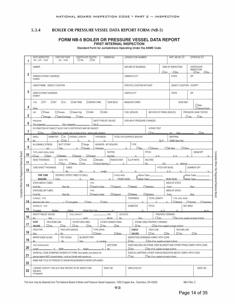
FORM NB-5 BOIlER OR PRESSURE vESSEl DATA REPORTFIRST INTERNAl INSPECTION
Standard Form for Jurisdictions Operating Under the ASME Code
DATE INSPECTED CERT EXP DATE CERTIFICATE POSTED OWNER NO. JURISDICTION NUMBER NAT’L BD NO. OTHER NO. MO | DAY | YEAR MO | YEAR Yes No
OWNER NATURE OF BUSINESS KIND OF INSPECTION CERTIFICATE INSPECTION Int Ext Yes No
OWNER’S STREET ADDRESS OWNER’S CITY STATE ZIP NUMBER
USER’S NAME - OBJECT LOCATION SPECIFIC LOCATION IN PLANT OBJECT LOCATION - COUNTY
USER’S STREET ADDRESS USER’S CITY STATE ZIP NUMBER
TYPE FT WT CI AIR TANK WATER TANK YEAR BUILT MANUFACTURER YEAR INST New Other Second Hand
USE Power Process Steam Htg HWH HWS FUEL (BOILER) METHOD OF FIRING (BOILER) PRESSURE GAGE TESTED
Storage Heat Exchange Other Yes No
PRESSURE SAFETY-RELIEF VALVES EXPLAIN IF PRESSURE CHANGED
This Inspection Prev. Inspection Set at
IS CONDITION OF OBJECT SUCH THAT A CERTIFICATE MAY BE ISSUED? HYDRO TEST
Yes No (If no, explain fully on back of form - listing code violation) Yes psi Date No
SHELL DIAMETER ID OVERALL LENGTH THICKNESS TOTAL HTG SURFACE (BOILER) MATERIAL
No. in. OD ft. in. in. Sq Ft ASME Spec Nos
ALLOWABLE STRESS BUTT STRAP Single HEADERS - WT BOILERS TYPE
psi Thks in Double Thickness in. Box Sinuous Wtr Wall Other
TYPE LONGITUDINAL SEAM RIVITED PITCH SEAM EFF
Lap Butt Welded Brazed Riveted Dia Hole in. in. X in. X in. %
HEAD THICKNESS HEAD TYPE Fixed Movable RADIUS DISH ELLIP RATIO BOLTING
in. Plus Minus Flat Quick Opening in. No. Dia. in. Material
TUBE SHEET THICKNESS TUBES PITCH (WT BLRS) LIGAMENT EFF
in. No. Dia. in. Length ft. in. in. X in. %
FIRE TUBE DISTANCE UPPER TUBES TO SHELL STAYED AREA Above Tubes Above Tubes
BOILERS Front in. Rear in. FRONT HEAD Below Tubes REAR HEAD Below Tubes
STAYS ABOVE TUBES TYPE AREA OF STAYS
Front No. Rear No. Head to Head Diagonal Welded Weldless Front Rear
STAYS BELOW TUBES TYPE AREA OF STAYS
Front No. Rear No. Head to Head Diagonal Welded Weldless Front Rear
FURNACE - TYPE THICKNESS TOTAL LENGTH TYPE LONG. SEAM
Adamson (No. Sect .) Corrugated Plain Other in. ft. in. Welded Riveted Seamless
STAYBOLTS - TYPE DIAMETER PITCH NET AREA
Threaded Welded Hollow Drilled (Size Hole in.) in. in. X in. sq. in.
SAFETY-RELIEF VALVES TOTAL CAPACITY Cfm OUTLETS PROPERLY DRAINED
No. Size Lb/Hr Btu/Hr No. Size Yes No (If no, explain on back of form)
STOP ON STEAM LINE ON RETURN LINES OTHER CONNECTIONS STEAM LINES PROPERLY DRAINED
VALVES Yes No Yes No Yes No Yes No (If no, explain on back of form)
FEED PIPE FEED APPLIANCES TYPE DRIVE CHECK FEED LINE RETURN LINE
Size in. No. Steam Motor VALVES Yes No Yes No
WATER GAGE GLASS TRY COCKS BLOWOFF PIPE INSPECTION OPENINGS COMPLY WTH CODE
No. No. Size in. Location Yes No (If no, explain on back of form)
CAST-IRON BOILERS SECTIONS DOES WELDING ON STEAM, FEED BLOWOFF AND OTHER PIPING COMPLY WITH CODE
Length in. Width in. Height in. No. Yes No (If no, explain on back of form)
SHOW ALL CODE STAMPING ON BACK OF FORM. Give details (use sketch) for DOES ALL MATERIAL OTHER THAN AS INDICATED ABOVE COMPLY WITH CODE
special objects NOT covered above - such as Double wall vessels etc. Yes No (If no, explain on back of form)
NAME AND TITLE OF PERSON TO WHOM REQUIREMENTS WERE EXPLAINED:
I HEREBY CERTIFY THIS IS A TRUE REPORT OF MY INSPECTION IDENT NO. EMPLOYED BY IDENT NO. Signature of Inspector
This form may be obtained from The National Board of Boiler and Pressure Vessel Inspectors, 1055 Crupper Ave., Columbus, OH 43229 NB-5 Rev. 0
5.3.4 boiler or Pressure vessel Data rePort form (nb-5)
1
2
3
4
5
6
7
8
9
10
11
12
13
14
15
16
17
18
19
20
21
22
23
{ {
Com
plet
e W
hen
Not
Reg
iste
red
Nat
iona
l Boa
rdC
omplete W
hen Not R
egistered National Board
93
NATIONAL BOARD INSPECTION CODE • PART 2 — INSPECTION
Page 14 of 35

5.3.5 boiler-fireD Pressure vessels rePort of insPection form (nb-6)
1
2
3
4
5
6
7
8
9
10
This form may be obtained from The National Board of Boiler and Pressure Vessel Inspectors, 1055 Crupper Ave., Columbus, OH 43229 NB-6 Rev. 4
FORM NB-6 BOIlER-FIRED PRESSURE vESSElREPORT OF INSPECTION
Standard Form for Jurisdictions Operating Under the ASME Code
DATE INSPECTED CERT EXP DATE CERTIFICATE POSTED OWNER NO. JURISDICTION NUMBER NAT’L BD NO. OTHER NO.
MO | DAY | YEAR MO | YEAR Yes No
OWNER NATURE OF BUSINESS KIND OF INSPECTION CERTIFICATE INSPECTION
Int Ext Yes No
OWNER’S STREET ADDRESS OWNER’S CITY STATE ZIP NUMBER
USER’S NAME – OBJECT LOCATION SPECIFIC LOCATION IN PLANT OBJECT LOCATION - COUNTY
USER’S STREET ADDRESS OWNER’S CITY STATE ZIP NUMBER
TYPE YEAR BUILT MANUFACTURER
FT WT CI Other
USE FUEL METHOD OF FIRING PRESSURE GAGE TESTED
Power Process Steam Htg HWH HWS Other Yes No
PRESSURE ALLOWED MAWP SAFETY-RELIEF VALVES HEATING SURFACE OR BTU (Input/Output)
This Inspection Prev. Inspection Set at Total Capacity
IS CONDITION OF OBJECT SUCH THAT A CERTIFICATE MAY BE ISSUED? HYDRO TEST
Yes No (If no, explain fully under conditions) Yes psi Date No
CONDITIONS: With respect to the internal surface, describe and state location of any scale, oil or other deposits. Give location and extent of any corrosion and state whether active or
inactive. State location and extent of any erosion, grooving, bulging, warping, cracking or similar condition. Report on any defective rivits, bowed, loose or broken stays. State condition of all
tubes, tube ends, coils, nipples, etc. Describe any adverse conditions with respect to pressure gage, water column, gage glass, gage cocks, safety valves, etc. Report condition of setting,
linings, baffles, supports, etc. Describe any major changes or repairs made since last inspection.
REQUIREMENTS: (List Code Violations)
NAME AND TITLE OF PERSON TO WHOM REQUIREMENTS WERE EXPLAINED:
I HEREBY CERTIFY THIS IS A TRUE REPORT OF MY INSPECTION
SIGNATURE OF INSPECTOR IDENT NO. EMPLOYED BY IDENT NO.
95
NATIONAL BOARD INSPECTION CODE • PART 2 — INSPECTION
Page 15 of 35

5.3.6 Pressure vessels rePort of insPection form (nb-7)FORM NB-7 PRESSURE vESSElS
REPORT OF INSPECTIONStandard Form for Jurisdictions Operating Under the ASME Code
1 DATE INSPECTEDMO | DAY | YEAR
CERT EXP DATEMO | YEAR
CERTIFICATE POSTED
Yes No
OWNER NO. JURISDICTION NUMBER NAT’L BD NO. OTHER NO.
2 OWNER NATURE OF BUSINESS KIND OF INSPECTION
Int Ext
CERTIFICATEINSPECTION
Yes No
OWNER’S STREET ADDRESS OWNER’S CITY STATE ZIP
3 USER’S NAME - OBJECT LOCATION SPECIFIC LOCATION IN PLANT OBJECT LOCATION - COUNTY
USER’S STREET ADDRESS USER’S CITY STATE ZIP
4 TYPE
AIR TANK WATER TANK OTHER
YEAR
BUILT
MANUFACTURER
5 USE
STORAGE PROCESS HEAT EXCHANGE OTHER
SIZE PRESSURE GAGE TESTED
Yes No
6 PRESSURE ALLOWED
THIS INSPECTION PREVIOUS INSPECTION
SAFETY RELIEF VALVES
SET AT TOTAL CAPACITY
EXPLAIN IF PRESSURE CHANGED
7 IS CONDITION OF OBJECT SUCH THAT A CERTIFICATE MAY BE ISSUED?
YES NO (IF NO, EXPLAIN FULLY UNDER CONDITIONS)
HYDRO TEST
YES PSI DATE NO
8 CONDITIONS: With respect to the internal surface, describe and state location of any scale, oil, or other deposits. Give location and extent of any corrosion and state whether active or inactive. State location and extent of any erosion, grooving, bulging, warping, cracking, or similar condition. Report on any defective rivits, bowed, loose or broken stays. State condition of all tubes, tube ends, coils, nipples, etc. Describe any adverse conditions with respect to pressure gage, water column, gage glass, gage cocks, safety valves, etc. Report condition of setting, linings, baffles, supports, etc. Describe any major changes or repairs made since last inspection.
9 REQUIREMENTS: (LIST CODE VIOLATIONS)
10 NAME AND TITLE OF PERSON TO WHOM REQUIREMENTS WERE EXPLAINED:
I HEREBY CERTIFY THIS IS A TRUE REPORT OF MY INSPECTION
SIGNATURE OF INSPECTOR
IDENT NO. EMPLOYED BY IDENT NO.
This form may be obtained from The National Board of Boiler and Pressure Vessel Inspectors, 1055 Crupper Ave., Columbus, OH 43229 NB-7 Rev. 2
97
NATIONAL BOARD INSPECTION CODE • PART 2 — INSPECTION
Page 16 of 35

Part 2 Inspection
NB10-0503 S1.4.2.23 HANDHOLE WASHOUT DOORS Handhole washout doors and their mating surfaces shall be inspected for: a) Damaged or cracked threads on the door studs b) Corrosion of door sealing surfaces and studs c) Cracks d) Stretching or bending of the door stud or handhole door e) Looseness f) Leakage and steam cuts g) Damage to the clamp h) Damage to the clamp seating surface on the sheet i) Confirmation that the handhole door makes unbroken line contact along the entire
circumference of the sheet at the opening j) Handhole doors and assembly components shall have proper fit at assembly k) Distortion of any of the components at assembly is prohibited jl) Material of the handhole door gaskets shall be suitable for the pressure and
temperature of service. k) Correct repairs Notes: Confirmation that the handhole door has unbroken line contact against sheet can be determined by performing a “blue check.” This requires applying a light coating of “contact blue” or “Prussian Blue” to the handhole door sealing surfaces. The door then is held against the sheet and removed. The transfer of the bluing will show the areas that contact the sheet surfaces. S7.7 FIRE DAMAGE c) A pressure vessel that has been subjected to the action of fire shall be removed from service until it has been properly evaluated. The general intent of this requirement is to remove from service pressure vessels which have been subject to the action of fire
Page 17 of 35

Part 2 Inspection
that has changed the metallurgical structure or the strength properties of the steel. Visual examination with emphasis given to the condition of the protective coating can be used to evaluate exposure from a fire. This is normally determined by visual
examination as described above with particular emphasis given to the condition of the protective coating. If there is evidence that the protective coating has been burned off any portion of the pressure vessel surface, or if the pressure vessel is burned, warped, or distorted, it is assumed that the pressure vessel has been overheated. If, however, the protective coating is only smudged, discolored, or blistered, and is found by examination to be intact underneath, the pressure vessel shall not be considered affected within the scope of this requirement. Vessels that have been involved in a fire and show no distortion shall be requalified for continued service by retesting using the hydrostatic liquid pressure test procedure applicable at the time of original fabrication.
Page 18 of 35

Part 3 Repairs and Alterations
Part 3 Repairs and Alterations
Page 19 of 35

Part 3 Repairs and Alterations
NB10-0401 1.3 INSPECTOR a) Inspection and certification shall be made by an Inspector holding a validthe
appropriate commission issued by the National Board and employed by an accredited Inservice Authorized Inspection Agency (see 9.0, Glossary of Terms, for definition of AIA).
NB10-0101 1.7.7.5 OUTLINE OF REQUIREMENTS FOR A QUALITY SYSTEM l) Valve Repair Nameplates An effective valve stamping system shall be established to ensure proper stamping of each valve as required by 5.9.2NBIC Part 3, 5.12.2. The manual shall include a
description of the nameplate or a drawing. NB11-0301 2.5.3.2 WELDING METHOD 2 i) For the welding process in NBIC Part 3, 2.5.2 c) use of austensic or ferritic filler
metals are permitted. For ferritic filler metals, use only electrodes and filler metals classified by the filler metal specification with a diffusible-hydrogen designator of H8 or lower.
2.5.3.3 WELDING METHOD 3 2) For the welding process in NBIC Part 3, 2.5.3.3 c) use of austensic or ferritic filler
metals are permitted. For ferritic filler metals, use only electrodes and filler metals classified by the filler metal specification with a diffusible-hydrogen designator of H8 or lower.
2.5.3.4 WELDING METHOD 4 2) For the welding process in NBIC Part 3, 2.5.3.4 c) use of austensic or ferritic filler
metals are permitted. For ferritic filler metals use only electrodes and filler metals classified by the filler metal specification with a diffusible hydrogen designator of H8 or lower.
NB11-0101 3.3.2 ROUTINE REPAIRS
20 of 35

Part 3 Repairs and Alterations
d) 3) Weld buildup of wasted areas in heads and shells not exceeding an area of 100 sq. in. (64, 520 sq. mm) or a thickness of 25% of nominal wall thickness of ½ in. (13 mm), whichever is less.
NB08-0304 5.2.1 PREPARATION OF FORM R-1 (REPAIRS) a) Using the instructions found at NBIC Part 3, 5.13.4.1, preparation of the Form R-1
shall be the responsibility of the “R” Certificate holder performing the repair.
b) Information describing the scope of work used to repair a Pressure Retaining Item (PRI) shall be documented on a Form R-1 and extended to a Form R-4 as needed to fully describe the repair activities completed per the instructions at NBIC Part 3, 5.13.4.1.
c) An Inspector shall indicate acceptance by signing the Form R-1, and Form R-4, if
attached d) The Form R-3, and Manufacturer’s Data Reports, and Certificates of Compliance
described in this section shall be a part of the completed Form R-1 and shall be attached thereto.
5.2.2 PREPARATION OF FORM R-2 (ALTERATIONS) c) Final preparation of Form R-2, including the gathering and attaching of supporting reports, shall be the responsibility of the “R” certificate holder that performed the construction portion of the alteration. The construction organization shall complete the Form R-2 provided by the design organization, including the “Construction
Certificate Certification” section of the form. When no construction work is performed (e.g., a re-rating with no physical changes), the “R” Certificate Holder responsible for the design shall prepare the Form R-2, including the gathering and attaching of supporting reports.
d) 2) Form R-3, Report of Fabricated Parts or Manufacturer’s Partial Data Reports, or
Certificates of Compliance; and 5.6 FORM “R” LOG The “R” Certificate Holder shall maintain a single, sequential log documenting unique and sequentially numbered Form “R” Reports of “R” Form numbers assigned for NBIC Report Forms (e.g., R-1, R-2, and R-3) that are registered with the National Board.
21 of 35
Part 3 Repairs and Alterations
NB10-0101 5.7.1 GENERAL The stamping of or attaching attachment of a nameplate to a pressure-retaining item shall indicate that the work was performed in accordance with the requirements of this Code. Such stamping or attaching of a nameplate shall be done only with the knowledge and authorization of the Inspector. The “R” certificate holder responsible for the repair or the construction portion of the alteration shall apply the stamping. For a rerating where no physical changes are made to the pressure-retaining item, the “R” certificate holder responsible for design shall apply the stamping. 5.85.11 REMOVAL OF ORIGINAL STAMPING OR NAMEPLATE If it becomes necessary to remove the original stamping, the Inspector shall, subject to the approval of the Jurisdiction, witness the making of a facsimile of the stamping, the obliteration of the old stamping, and the transfer of the stamping to the new item. When the stamping is on a nameplate, the Inspector shall witness the transfer of the nameplate to the new location. Any relocation shall be described on the applicable NBIC “R” Form. Re-stamping or replacement of a code symbol stamp shall be performed only as permitted by the governing code of construction. 5.95.12 STAMPING REQUIREMENTS FOR PRESSURE RELIEF DEVICES 5.9.1 5.12.1 NAME PLATES Proper marking and identification of tested or repaired valves is critical to ensuring acceptance during subsequent inspections, and also provide for traceability and identification of any changes made to the valve. All operations that require the valve’s seals to be replaced shall be identified by a nameplate as described in NBIC Part 3, 5.9.25.12.2 or 5.9.45.12.4. 5.9.2 5.12.2 REPAIR NAME PLATE When a pressure relief valve is repaired, a metal repair nameplate stamped with the information required below shall be securely attached to the valve adjacent to the original manufacturer’s stamping or nameplate. If not mounted directly on the valve, the nameplate shall be securely attached so as not to interfere with valve operation and sealed in accordance with the quality system. 5.9.3 5.12.3 CHANGES TO ORIGINAL PRESSURE RELIEF VALVE NAME PLATE
INFORMATION b) If the service fluid is changed, the capacity, including units, on the original nameplate or stamping shall be marked out but left legible. The new capacity shall be based on that for which the valve was originally certified, or if a conversion has been made, as described in NBIC Part 3, S7.2 on the capacity certification for the valve as converted.
22 of 35

Part 3 Repairs and Alterations
5.9.4 5.12.4 TEST ONLY NAME PLATE a) Where a valve has been tested and adjusted, as permitted by NBIC Part 3, S7.10.1,
but not otherwise repaired, a “Test Only” nameplate shall be applied that contains the following information:
5.9.55.12.5 REPLACEMENT OF ILLEGIBLE OR MISSING NAME PLATES a) Illegible Nameplates When the information on the original manufacturer’s or assembler’s nameplate or stamping is illegible, but traceability can be confirmed, the nameplate or stamping will be augmented by a nameplate furnished by the “VR” stamp holder stamped “Duplicate.”
It shall contain all information that originally appeared on the nameplate or valve, as required by the applicable section of the ASME Code, except the “V,” “HV,” or “UV” symbol and the National Board mark. The repair organization’s nameplate, with the “VR” stamp and other required data specified in 5.9.2NBIC Part 3, 5.12.2, will make the repairer responsible to the owner and the Jurisdiction that the information on the duplicate nameplate is correct. b) Missing Nameplates When the original valve nameplate is missing, the repair organization is not authorized to perform repairs to the valve under the “VR” program, unless positive identification can be made to that specific valve and verification that the valve was originally stamped with an ASME “V” or “UV” symbol or marked with an ASME “HV” symbol. Valves that can be positively identified will be equipped with a duplicate nameplate, as described in this section, in addition to the repairer’s “VR”-stamped nameplate. The repairer’s responsibilities for accurate data, as defined in 5.9.5(a)NBIC Part 3, 5.12.5 a)(Illegible Nameplates), shall apply. 5.115.8 STAMPING FOR FIBER REINFORCED VESSELS The attaching attachment of a nameplate to a repaired or altered vessel or tank shall indicate that the work was performed in accordance with the requirements of this Code. The attachment of a nameplate shall be done only with the knowledge and authorization of the Inspector. The certificate holder responsible for the repair or alteration shall apply the stamping nameplate. Required stamping and nameplate information are shown in NBIC Part 3, 5.7. 5.11.25.8.1 STAMPING FOR REPAIRS Pressure-retaining items repaired in accordance with the NBIC shall have a nameplate as required by Section NBIC Part 3, 5.7 Subject to the acceptance of the jurisdiction and the concurrence of the Inspector, nameplates may not be required for routine
23 of 35

Part 3 Repairs and Alterations
repairs. (See NBIC Part 3, 5.7.2[b]). In all cases, the type and extent of repairs necessary shall be considered prior to waiving the requirement. 5.11.35.8.2 STAMPING FOR ALTERATIONS The nameplate shall be applied in accordance with NBIC Part 3, Section 5.7. The lLocation of the nameplate shall be documented on the Form R-2. 5.12 5.9STAMPING REQUIREMENTS FOR YANKEE DRYERS b) Stamping is required for repairs that do affect the pressure-retaining capability of the Yankee Dryer shell, as indicated on the De-rate Curve, or other pressure-retaining
parts as indicated on the original Manufacturer’s Data Report. c) Stamping is required for alterations as listed in NBIC Part 3, S5.7.2. d) Stamping, when required, shall meet the requirements for stamping in NBIC Part 3,
5.7.32. The location of stamping shall be described in the “remarks” section of Form R-2.
NB08-0304 5.13.4.1 GUIDE INSTRUCTIONS FOR COMPLETING NATIONAL BOARD FORM “R”
REPORTS
These instructions are to be used when completing the National Board Form “R” Reports. When computer generated, the format of the form shall replicate the type and relative location of the information depicted on the Form “R” Reports shown in NBIC Part 3, 5.13.1 through 5.13.4.
1. The name and address of the “R” Certificate Holder performing the work as it appears
on the “Certificate of Authorization”. On a Form R-2, the organization that performed the design-work will complete sheet 1 of 2, and the organization completing the construction activities will complete sheet 2 of 2. Name and address of the “R” Certificateorganization that performed the work. OnForm R-2, the organization that performed the construction work (Line 1a) or the design(Line 1b).
2. When registering a Form “R”-Report with the National Board, this line is solely
designated for a unique sequential number assigned by the “R” Certificate Holder. When the “R” Form is not to be registered, indicate so by “N/A”. As described in NBIC Part 3,5.6, a log shall be maintained identifying sequentially, any Form “R” registered with the National Board.For NBIC Report Forms registered with the National Board, indicate the sequential Form R Number assigned by the “R” Certificate organization that is registering the form; otherwise indicate “N/A.” For re-rating only, the Design Organization registers the Form R-2. Where physical work is also performed, the Construction Organization registers the Form R-2.
24 of 35

Part 3 Repairs and Alterations
5. Description of the pressure-retaining item, such as boiler or pressure vessel, or piping. Include the unit identification if applicable.
6. Name of the original manufacturer of the pressure-retaining item if a boiler or
pressure vessel. If other than a boiler or pressure vessel, complete if known. If the original manufacturer is unknown, indicate by, “unknown”.
7. Document the Sserial number of the pressure-retaining item as if assigned by the
original manufacturer. If there is no serial number assigned or is unknown, indicate “unknown”.
8. When the pressure-retaining item is registered with the National Board, document
the applicable registration number. Identification of the pressure-retaining item by applicable registration number. If the pressure-retaining item is installed in Canada, indicate the Canadian Design Registration number (CRN), and list the drawing number under “other.”If the item is not registered, indicate, “none”.
12. State exact scope of work, and attach additional data, sketch, Form R-4, etc. as
necessary. If additional data is attached, so state. Provide a summary describing the exact scope of work that was completed to a Pressure Retaining Item (PRI). The information to be included when describing the scope of work shall consider items such as, the nature of the repair or alteration characterized by the listed examples, the specific location of the work performed to the PRI, the method of repair used to include as applicable, the steps taken to remove a defect or as allowed by NBIC Part 3, 3.3.4.8 to remain in place, the welding process and procedure when used, any special processes required such as PWHT; noting the soak time and temperatures recorded, and any acceptable in-process and final NDE-examinations or tests performed. When additional space is needed to fully describe the scope of work, a Form R-4 shall be used and attached.
14.To be completed for all welded pressure components added during the work. As
applicable, identify what parts manufactured by welding or bonding were introduced as needed to complete the scope of work. Indicate the part, item number,
manufacturer’s name, stamped identification, data report type or certificate of compliance. 16. Type or print name of authorized representative of the “R” Certificate Holder attesting to accuracy of the work described. 20. Record name of the “R” Certificate organization Holder that which performed the
identified described work, using full name as shown on the Certificate of Authorization or an abbreviation acceptable to the National Board.
29. Document name and address of the organization that purchased the parts for
incorporation into the repair or alteration. if known. If the part’s origin is unknown or the part was built for stock, so state.
25 of 35

Part 3 Repairs and Alterations
30. Document name of organization responsible for specifying code design conditions, if known. If origin of design conditions are unknown, state “unknown”.
31. Document name of organization responsible for performing code design, if known. If
code design organization is unknown, state “unknown”. 32. Name, section, and division of the design code, if known. If the design is unknown, state “unknown”.
35. Indicate the code paragraph reference for formula used to establish the MAWP, if known. If the code reference of the formula is unknown, state “unknown”.
36. Identify name of part, such as “superheater header”. If available, identify component
by part’s original name, function, or use the original equipment manufacturer’s “mark or item-number.”
53. If applicable, document the unique purchase order, job, or tracking number, etc., assigned by the organization performing the work.
26 of 35

FORM R-1 REPORT OF REPAIR in accordance with provisions of the National Board Inspection Code
1. Work performed by (name of repair organization) Form-R Registration No.)
(P.O. No. Job No. etc.)
2. Owner (name)
(address)
3. Location of installation (name)
(address)
4. Item identification Name of original manufacturer (boiler, pressure vessel, or piping)
5. Identifying nos.: (mfg. serial no.) (National Board No.) (jurisdiction no.) (other) (year built)
6. NBIC Edition / Addenda: (edition) (addenda)
Original Code of Construction for Item: (name / section / division) (edition / addenda)
Construction Code Used for Repair Performed: (name / section / division) (edition / addenda)
7. Repair Type: Welded Graphite Pressure Equipment FRP Pressure Equipment
8. Description of work: (use Form R-4, if necessary)
Form R-4, Report Supplementary Sheet is attached
FFSA Form (NB-403) is attached Pressure Test, if applied psi MAWP psi
9. Replacement Parts. Attached are Manufacturer’s Partial Data Reports or Form R-3’s properly completed for the following items of this report:
(name of part, item number, data report type or Certificate of Compliance, mfg's. name and identifying stamp) 10. Remarks:
CERTIFICATE OF COMPLIANCE
I, certify that to the best of my knowledge and belief the statements in this report are correct and that all material, construction, and workmanship on this Repair conforms to the National Board Inspection Code. National Board “R” Certificate of Authorization No. expires on Date Signed (name of repair organization) (authorized representative)
CERTIFICATE OF INSPECTION
I, holding a valid Commission issued by the National Board of Boiler and Pressure Vessel Inspectors and certificate of competency issued by the jurisdiction of and employed by of have inspected the work described in this report on and state that to the best of my knowledge and belief this work complies with the applicable requirements of the National Board Inspection Code. By signing this certificate, neither the undersigned nor my employer makes any warranty, expressed or implied, concerning the work described in this report. Furthermore, neither the undersigned nor my employer shall be liable in any manner for any personal injury, property damage or loss of any kind arising from or connected with this inspection.
Date Signed Commissions (inspector) (National Board and Jurisdiction No.)
This form may be obtained from The National Board of Boiler and Pressure Vessel Inspectors, 1055 Crupper Ave., Columbus, OH 43229 NB-66 Rev. 12

FORM R-2 REPORT OF ALTERATION in accordance with provisions of the National Board Inspection Code
DESIGN REPORT SHEET 1 OF 2
1. Design performed by (name of “R” organization responsible for design) (Form “R” Registration No.)
(address) (P.O. No., Job No., etc.)
2. Owner (name)
(address)
3. Location of installation (name)
(address)
4. Item identification Name of original manufacturer (boiler, pressure vessel, or piping)
5. Identifying nos.: (mfg. serial no.) (National Board No.) (jurisdiction no.) (other) (year built)
6. NBIC Edition / Addenda: (edition) (addenda)
Original Code of Construction for Item: (name / section / division) (edition / addenda)
Construction Code to be Used for Alteration Performed: (name / section / division) (edition / addenda)
7. Description of Design Scope:
(use supplemental sheet, Form R-4, if necessary)
FORM R-4, REPORT SUPPLEMENTARY SHEET IS ATTACHED Pressure Test, if applied psi MAWP psi
8. Replacement Parts. Attached are Manufacturer’s Partial Data Reports or Form R-3’s properly completed for the following items of this report:
(name of part, item number, data report type or Certificate of Compliance, mfg's. name and identifying stamp)
9. Remarks:
DESIGN CERTIFICATION
I, certify that to the best of my knowledge and belief the statements in this report are correct and that the Design Change described in this report conforms to the National Board Inspection Code. National Board “R” Certificate of Authorization No. expires on Date Signed (name of design organization) (authorized representative)
CERTIFICATE OF DESIGN CHANGE REVIEW
I, holding a valid Commission issued by The National Board of Boiler and Pressure Vessel Inspectors and certificate of competency issued by the jurisdiction of and employed by of have reviewed the design change as described in this report and state that to the best of my knowledge and belief such change complies with the applicable requirements of the National Board Inspection Code. By signing this certificate, neither the undersigned nor my employer makes any warranty, expressed or implied, concerning the work described in this report. Furthermore, neither the undersigned nor my employer shall be liable in any manner for any personal injury, property damage or loss of any kind arising from or connected with this inspection. Date Signed Commissions (inspector) (National Board and jurisdiction no.)

FORM R-2 REPORT OF ALTERATION in accordance with provisions of the National Board Inspection Code
CONSTRUCTION REPORT SHEET 2 OF 2
1. Construction performed by (name of “R” organization responsible for construction) (Form “R” Registration No.)
(address) (P.O. No., Job No., etc.)
2. Owner (name)
(address)
3. Location of installation (name)
(address)
4. Item identification Name of original manufacturer (boiler, pressure vessel, or piping)
5. Identifying nos.: (mfg. serial no.) (National Board No.) (jurisdiction no.) (other) (year built)
CERTIFICATE of DESIGN , ACKNOWLEDGED by CONSTRUCTION ORGANIZATION (Identify the design organization’s Form “R” Registration No. or referencing P.O., job, or tracking number if the Form “R” Report is not registered)
I, acknowledge the provisions and requirements of design described on the DESIGN REPORT, sheet 1, and the design was introduced into the construction scope as required by the National Board Inspection Code. Date Signed (name of construction organization) (authorized representative)
7. Description of Construction Scope:
(use supplemental sheet, Form R-4, if necessary)
FORM R-4, REPORT SUPPLEMENTARY SHEET IS ATTACHED
Pressure Test, if applied psi MAWP psi 8. Replacement Parts. Attached are Manufacturer’s Partial Data Reports or Form R-3’s properly
completed for the following items of this report: (name of part, item number, data report type or Certificate of Compliance, mfg's. name and identifying stamp) 9. Remarks:
CONSTRUCTION CERTIFICATION
I, certify that to the best of my knowledge and belief the statements in this report are correct and that all material, construction, and workmanship on this Alteration conforms to the National Board Inspection Code. National Board “R” Certificate of Authorization No. expires on Date Signed (name of alteration organization) (authorized representative)
CERTIFICATE OF INSPECTION
I, holding a valid Commission issued by the National Board of Boiler and Pressure Vessel Inspectors and certificate of competency issued by the jurisdiction of and employed by of have inspected the work described in this report on and state that to the best of my knowledge and belief this work complies with the applicable requirements of the National Board Inspection Code. By signing this certificate, neither the undersigned nor my employer makes any warranty, expressed or implied, concerning the work described in this report. Furthermore, neither the undersigned nor my employer shall be liable in any manner for any personal injury, property damage or loss of any kind arising from or connected with this inspection. Date Signed Commissions (inspector) (National Board and jurisdiction no.)
This form may be obtained from The National Board of Boiler and Pressure Vessel Inspectors, 1055 Crupper Ave., Columbus, OH 43229 NB-229 Rev. 5

Part 3 Repairs and Alterations
NB10-0102 S1.2.10 REPAIRS AND ALTERATIONS TO BOILER BARREL UNSTAYED AREAS a) Defects such as cracks and wastage may be repaired by weld buildup, a welded
flush patch or a riveted patch. Installation of a riveted patch shall be considered an alteration. Prior to repairing cracks, the plate shall be examined for defects. Affected sections shall be repaired.
a) Except as provided in NBIC Part 3, 3.4.4.8, a repair of a defect in a welded joint or
base material shall not be made until the defect shall be removed. A suitable Nondestructive Examination (NDE) method such as Magnetic Particle (MT) or Liquid Penetrant (PT) may be necessary to ensure complete removal of the defect. If the defect penetrates the full thickness of the material, the repair shall be made with a full penetration weld such as a double buttweld or a single buttweld with or without backing. Where circumstances indicate that the defect is likely to recur, consideration should be given to removing the defective area and installing a flush patch or taking other corrective measures acceptable to the Inspector and when required by the Jurisdiction.
30 of 35

31 of 35

Part 3 Repairs and Alterations
NB10-0504 S2.13.14.4 Handhole doors, studs, nuts, yokes, and clamps which are worn, cracked or otherwise damaged shall be replaced and not repaired. Replacements shall be of new manufacture, rated for the pressure and temperature of service. NB10-0302 S3.2 d) When ASME is the original code of construction, replacement parts subject to internal or external pressure, which require shop inspection by an Authorized Inspector, shall be fabricated by an organization having an appropriate ASME Certificate of Authorization. The item shall be inspected and stamped as required by the applicable section of the ASME Code. A completed ASME Manufacturer’s Partial Data Report shall be supplied by the manufacturer. Further, all impregnated graphite material subject to internal or external pressure shall be fabricated by an organization having the appropriate ASME Certificate of Authorization. The impregnated graphite material shall be inspected and stamped as required by the applicable section of the ASME Code. A completed ASME Manufacturer’s Partial Data Report with supplementary U1B shall be supplied by the impregnated graphite material manufacturer. . NB10-0106 S4.16.3 REPAIR PLAN a) Professional Engineer Review The repair plan shall be reviewed and certified by a Professional Engineer who is
registered in one or more of the states of the United States of America or the provinces of Canada and is experienced in reinforced plastic vessel design. The review and certification shall be such to ensure that the work involved in the repair is compatible with the User’s Design Specification or User’s Basic Requirements Specification and the Manufacturer’s Fabricator’s Design Report. The certification shall also include any drawings and calculations prepared as part of the repair plan.
NB10-0107 S4.18.1 b) GENERAL REQUIREMENTS b) The repair or alteration shall meet the requirements of the original construction
standard. NB10-0109 S6.17
32 of 35

Part 3 Repairs and Alterations
The following requirements shall apply to all repairs, alterations, or modifications to
pressure retaining items. S7.2 GENERAL REQUIREMENTS b) Conversions, changes, or adjustments affecting critical parts are also considered
repairs. The scope of conversions may include changes in service fluid and changes such as bellows, soft seats, and other changes that may affect Type/Model number provided such changes are recorded on the document as required for a quality system and the repair nameplate. (See NBIC Part 3, 5.912.1).
S7.14.2 SPRING-LOADED PRESSURE RELIEF VALVES l) Nameplate The repairer will place a repair nameplate on each repaired valve. The nameplate shall, as a minimum, meet the requirements of 5.9.1 NBIC Part 3, 5.12.1. S7.14.3 PILOT OPERATED SAFETY RELIEF VALVES g) Nameplate The repairer will place a repair nameplate on each repaired valve. The nameplate, as a minimum, shall meet the requirements of 5.9.1NBIC Part 3, 5.12.1. S9.3 GENERAL RULES e) When an ASME “NV”-stamped pressure relief device requires a duplicate nameplate because the original nameplate is illegible or missing, it may be applied using the procedures of 5.9.5 NBIC Part 3, 5.12.5 provided concurrence is obtained from the Authorized Nuclear Inspector and Jurisdiction. In this case the nameplate shall be marked “SEC. III” to indicate the original ASME Code stamping.
33 of 35

Glossary
Glossary
34 of 35

Glossary
Authorized Inspection Agency – New Construction: An Authorized Inspection Agency is one that is accredited by the National Board meeting the qualification and duties definition in NB-360, Criteria for Acceptance of Authorized Inspection Agencies for New Construction.
Appliance- A piece of equipment that includes all controls, safety devices, piping,
fittings, and vessel (s) within a common frame or enclosure that is listed and labeled by a nationally recognized testing agency for its intended use.
Potable Water Heaters- A corrosion resistant appliance that includes the controls and
safety devices to supply potable hot water at pressures not exceeding 160 psig (1100 kPa) and temperatures not in excess of 210°F (99°C).
1) Fired Storage Water Heater-A potable water heater in which water is
heated by electricity, the combustion of solid, liquid, or gaseous fuels and stores water within the same appliance.
2) Indirect Fired Water Heater- A potable water heater in which water is
heated by an internal coil or heat exchanger that receives its heat from an external source. Indirect fired water heaters provide water directly to the system or store water within the same appliance.
3) Circulating Water Heater- A potable water heater which furnishes water
directly to the system or to a separate storage tank. Circulating water heaters may be either natural or forced flow.