dr4500a classic series circular chart recorder with or ... · release m dr4500a classic series...
TRANSCRIPT

Honeywell Field Solutions
DR4500A Classic Series Circular Chart
Recorder With or Without Control
Product Manual
Doc. No.: 44-45-25-35
Release: M
Last Revision Date: April 2017
ii DR4500A Classic Series Circular Chart Recorder With or Without Control Product Manual Release M April 2017
Notices and Trademarks
Copyright 2017 by Honeywell Release M – April 2017
WARRANTY/REMEDY
Honeywell warrants goods of its manufacture as being free of defective materials and faulty workmanship. Contact your local sales office for warranty information. If warranted goods are returned to Honeywell during the period of coverage, Honeywell will repair or replace without charge those items it finds defective. The foregoing is Buyer's sole remedy and is in lieu of all other warranties, expressed or implied, including those of merchantability and fitness for a particular purpose. Specifications may change without notice. The information we supply is believed to be accurate and reliable as of this printing. However, we assume no responsibility for its use.
While we provide application assistance personally, through our literature and the Honeywell web site, it is up to the customer to determine the suitability of the product in the application.
Honeywell Process Solutions
1250 W Sam Houston Pkwy S
Houston, TX 77042
DR4500 is a trademark of Honeywell
Modbus is a registered trademark of Modicon
Other brand or product names are trademarks of their respective owners.
Release M DR4500A Classic Series Circular Chart Recorder With or Without Control Product Manual iii April 2017
About This Document
Revision Information
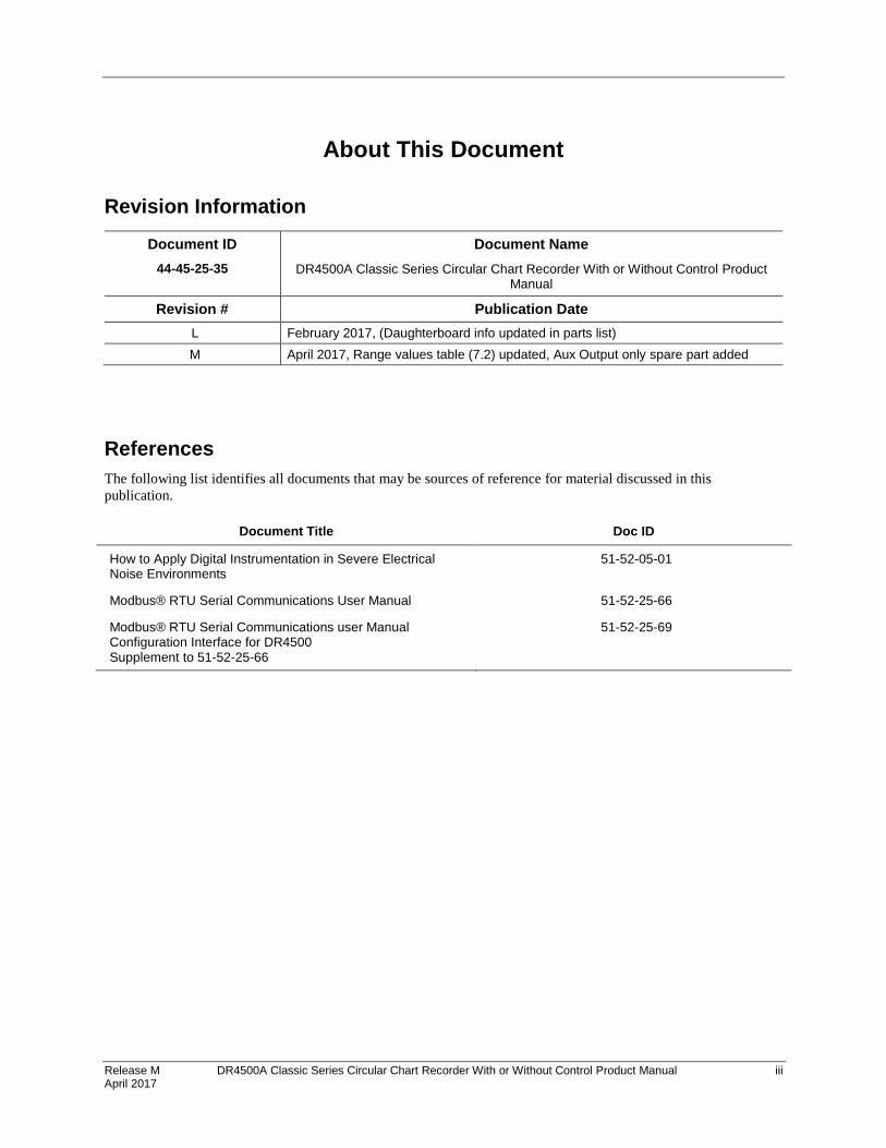
Document ID
44-45-25-35
Document Name
DR4500A Classic Series Circular Chart Recorder With or Without Control Product Manual
Revision # Publication Date
L February 2017, (Daughterboard info updated in parts list)
M April 2017, Range values table (7.2) updated, Aux Output only spare part added
References
The following list identifies all documents that may be sources of reference for material discussed in this
publication.
Document Title Doc ID
How to Apply Digital Instrumentation in Severe Electrical Noise Environments
51-52-05-01
Modbus® RTU Serial Communications User Manual 51-52-25-66
Modbus® RTU Serial Communications user Manual Configuration Interface for DR4500 Supplement to 51-52-25-66
51-52-25-69
iv DR4500A Classic Series Circular Chart Recorder With or Without Control Product Manual Release M April 2017
Support and Contact Information
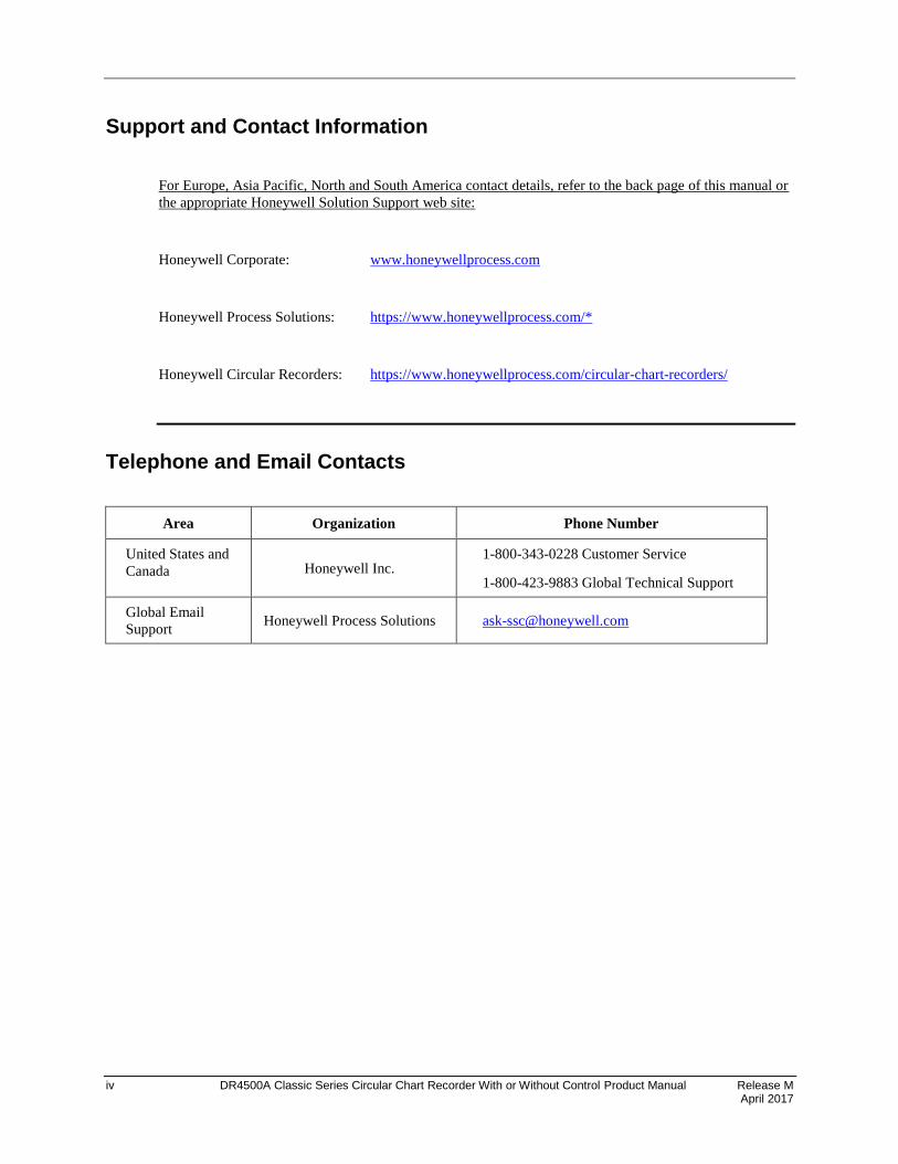
For Europe, Asia Pacific, North and South America contact details, refer to the back page of this manual or
the appropriate Honeywell Solution Support web site:
Honeywell Corporate: www.honeywellprocess.com
Honeywell Process Solutions: https://www.honeywellprocess.com/*
Honeywell Circular Recorders: https://www.honeywellprocess.com/circular-chart-recorders/
Telephone and Email Contacts
Area Organization Phone Number
United States and
Canada Honeywell Inc. 1-800-343-0228 Customer Service
1-800-423-9883 Global Technical Support
Global Email
Support Honeywell Process Solutions [email protected]
Release M DR4500A Classic Series Circular Chart Recorder With or Without Control Product Manual v April 2017
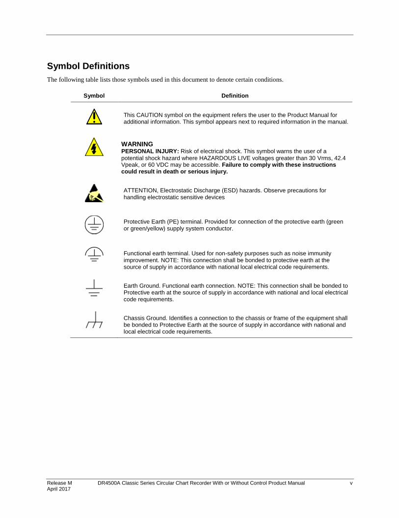
Symbol Definitions
The following table lists those symbols used in this document to denote certain conditions.
Symbol Definition
This CAUTION symbol on the equipment refers the user to the Product Manual for additional information. This symbol appears next to required information in the manual.
WARNING
PERSONAL INJURY: Risk of electrical shock. This symbol warns the user of a
potential shock hazard where HAZARDOUS LIVE voltages greater than 30 Vrms, 42.4 Vpeak, or 60 VDC may be accessible. Failure to comply with these instructions could result in death or serious injury.
ATTENTION, Electrostatic Discharge (ESD) hazards. Observe precautions for handling electrostatic sensitive devices
Protective Earth (PE) terminal. Provided for connection of the protective earth (green or green/yellow) supply system conductor.
Functional earth terminal. Used for non-safety purposes such as noise immunity improvement. NOTE: This connection shall be bonded to protective earth at the source of supply in accordance with national local electrical code requirements.
Earth Ground. Functional earth connection. NOTE: This connection shall be bonded to Protective earth at the source of supply in accordance with national and local electrical code requirements.
Chassis Ground. Identifies a connection to the chassis or frame of the equipment shall be bonded to Protective Earth at the source of supply in accordance with national and local electrical code requirements.

vi DR4500A Classic Series Circular Chart Recorder With or Without Control Product Manual Release M April 2017
Contents
1. Overview ............................................................................................ 1
1.1 Introduction ........................................................................................................ 1
1.2 Operator Interface ............................................................................................. 3
1.3 Set-up Tasks ..................................................................................................... 5
2. Installation .......................................................................................... 7
2.1 Overview ............................................................................................................ 7
2.2 Model Number Interpretation ........................................................................... 13
2.3 Mounting Considerations and Overall Dimensions ......................................... 16
2.4 Mounting Methods ........................................................................................... 17
2.5 Wiring Prerequisites ........................................................................................ 27
2.6 Input Wiring Procedures .................................................................................. 29
2.7 Output Wiring Procedures ............................................................................... 39
2.8 Option Wiring Procedures ............................................................................... 45
2.9 Lockout Switch Configuration .......................................................................... 54
3. Configuration ................................................................................... 55
3.1 Overview .......................................................................................................... 55
3.2 Configuration Prompts ..................................................................................... 56
3.3 How To Get Started ......................................................................................... 58
3.4 Configuration Tips ........................................................................................... 59
3.5 Configuration Procedure ................................................................................. 60
3.6 Input Set Up Group.......................................................................................... 62
3.7 Pen Set Up Group ........................................................................................... 64
3.8 Chart Set Up Group ......................................................................................... 65
3.9 Totalizer Set Up Group .................................................................................... 66
3.10 Control Set Up Group ...................................................................................... 67
3.11 Tuning Parameters Set Up Group ................................................................... 69
3.12 SP Ramp Set Up Groups ................................................................................ 70
3.13 Timer Set Up Group ........................................................................................ 71
3.14 Alarms Set Up Group ...................................................................................... 72
3.15 Auxiliary Output Set Up Group ........................................................................ 74
3.16 Modbus Communications Set Up Group ......................................................... 75
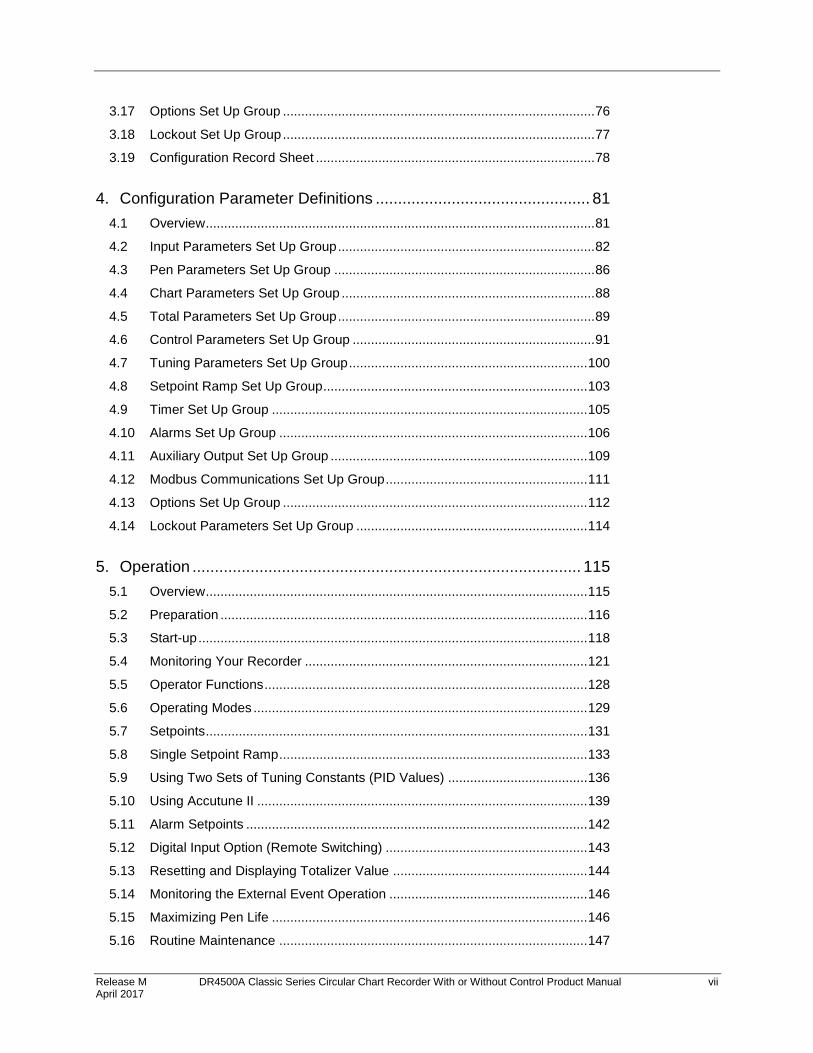
Release M DR4500A Classic Series Circular Chart Recorder With or Without Control Product Manual vii April 2017
3.17 Options Set Up Group ..................................................................................... 76
3.18 Lockout Set Up Group ..................................................................................... 77
3.19 Configuration Record Sheet ............................................................................ 78
4. Configuration Parameter Definitions ................................................ 81
4.1 Overview .......................................................................................................... 81
4.2 Input Parameters Set Up Group ...................................................................... 82
4.3 Pen Parameters Set Up Group ....................................................................... 86
4.4 Chart Parameters Set Up Group ..................................................................... 88
4.5 Total Parameters Set Up Group ...................................................................... 89
4.6 Control Parameters Set Up Group .................................................................. 91
4.7 Tuning Parameters Set Up Group ................................................................. 100
4.8 Setpoint Ramp Set Up Group ........................................................................ 103
4.9 Timer Set Up Group ...................................................................................... 105
4.10 Alarms Set Up Group .................................................................................... 106
4.11 Auxiliary Output Set Up Group ...................................................................... 109
4.12 Modbus Communications Set Up Group ....................................................... 111
4.13 Options Set Up Group ................................................................................... 112
4.14 Lockout Parameters Set Up Group ............................................................... 114
5. Operation ....................................................................................... 115
5.1 Overview ........................................................................................................ 115
5.2 Preparation .................................................................................................... 116
5.3 Start-up .......................................................................................................... 118
5.4 Monitoring Your Recorder ............................................................................. 121
5.5 Operator Functions ........................................................................................ 128
5.6 Operating Modes ........................................................................................... 129
5.7 Setpoints ........................................................................................................ 131
5.8 Single Setpoint Ramp .................................................................................... 133
5.9 Using Two Sets of Tuning Constants (PID Values) ...................................... 136
5.10 Using Accutune II .......................................................................................... 139
5.11 Alarm Setpoints ............................................................................................. 142
5.12 Digital Input Option (Remote Switching) ....................................................... 143
5.13 Resetting and Displaying Totalizer Value ..................................................... 144
5.14 Monitoring the External Event Operation ...................................................... 146
5.15 Maximizing Pen Life ...................................................................................... 146
5.16 Routine Maintenance .................................................................................... 147
viii DR4500A Classic Series Circular Chart Recorder With or Without Control Product Manual Release M April 2017
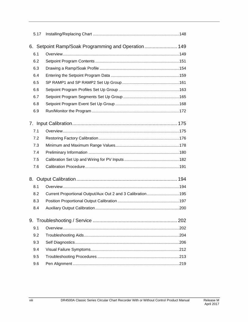
5.17 Installing/Replacing Chart ............................................................................. 148
6. Setpoint Ramp/Soak Programming and Operation ........................ 149
6.1 Overview ........................................................................................................ 149
6.2 Setpoint Program Contents ........................................................................... 151
6.3 Drawing a Ramp/Soak Profile ....................................................................... 154
6.4 Entering the Setpoint Program Data ............................................................. 159
6.5 SP RAMP1 and SP RAMP2 Set Up Group ................................................... 161
6.6 Setpoint Program Profiles Set Up Group ...................................................... 163
6.7 Setpoint Program Segments Set Up Group .................................................. 165
6.8 Setpoint Program Event Set Up Group ......................................................... 168
6.9 Run/Monitor the Program .............................................................................. 172
7. Input Calibration ............................................................................. 175
7.1 Overview ........................................................................................................ 175
7.2 Restoring Factory Calibration ........................................................................ 176
7.3 Minimum and Maximum Range Values......................................................... 178
7.4 Preliminary Information ................................................................................. 180
7.5 Calibration Set Up and Wiring for PV Inputs ................................................. 182
7.6 Calibration Procedure .................................................................................... 191
8. Output Calibration .......................................................................... 194
8.1 Overview ........................................................................................................ 194
8.2 Current Proportional Output/Aux Out 2 and 3 Calibration ............................. 195
8.3 Position Proportional Output Calibration ....................................................... 197
8.4 Auxiliary Output Calibration ........................................................................... 200
9. Troubleshooting / Service .............................................................. 202
9.1 Overview ........................................................................................................ 202
9.2 Troubleshooting Aids ..................................................................................... 204
9.3 Self Diagnostics ............................................................................................. 206
9.4 Visual Failure Symptoms ............................................................................... 212
9.5 Troubleshooting Procedures ......................................................................... 213
9.6 Pen Alignment ............................................................................................... 219

Release M DR4500A Classic Series Circular Chart Recorder With or Without Control Product Manual ix April 2017
10. Parts List ........................................................................................ 222
10.1 Overview ........................................................................................................ 222
10.2 Exploded Views ............................................................................................. 223
10.3 Miscellaneous Hardware Kit Contents .......................................................... 230
10.4 Internal Cabling Data – Without Options ....................................................... 232
10.5 Internal Wiring Diagram – Options Only ........................................................ 233
A. Foreign Language Safety Instructions ........................................... 235
DA2I-6057 ................................................................................................................ 236
DU2I-6057 ................................................................................................................ 237
FI2I-6057 .................................................................................................................. 238
FR2I-6057 ................................................................................................................. 238
GE2I-6057 ................................................................................................................ 240
GR2I-6057 ................................................................................................................ 241
IT2I-6057 .................................................................................................................. 242
NO2I-6057 ................................................................................................................ 243
PO2I-6057 ................................................................................................................ 244
SP2I-6057 ................................................................................................................. 245
SW2I-6057 ................................................................................................................ 246
Index ................................................................................................... 247
x DR4500A Classic Series Circular Chart Recorder With or Without Control Product Manual Release M April 2017
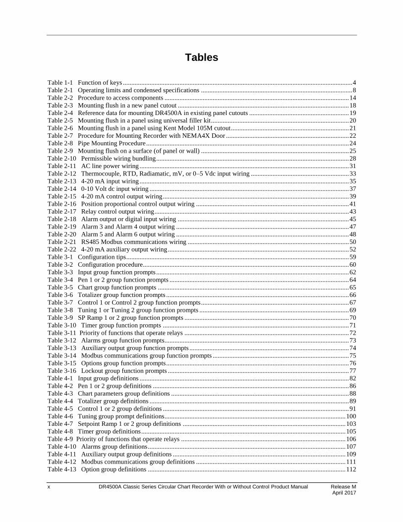
Tables
Table 1-1 Function of keys .......................................................................................................................................... 4 Table 2-1 Operating limits and condensed specifications ........................................................................................... 8 Table 2-2 Procedure to access components ............................................................................................................... 14 Table 2-3 Mounting flush in a new panel cutout ....................................................................................................... 18 Table 2-4 Reference data for mounting DR4500A in existing panel cutouts ............................................................ 19 Table 2-5 Mounting flush in a panel using universal filler kit ................................................................................... 20 Table 2-6 Mounting flush in a panel using Kent Model 105M cutout ....................................................................... 21 Table 2-7 Procedure for Mounting Recorder with NEMA4X Door .......................................................................... 22 Table 2-8 Pipe Mounting Procedure .......................................................................................................................... 24 Table 2-9 Mounting flush on a surface (of panel or wall) ......................................................................................... 25 Table 2-10 Permissible wiring bundling .................................................................................................................... 28 Table 2-11 AC line power wiring .............................................................................................................................. 31 Table 2-12 Thermocouple, RTD, Radiamatic, mV, or 0–5 Vdc input wiring ........................................................... 33 Table 2-13 4-20 mA input wiring .............................................................................................................................. 35 Table 2-14 0-10 Volt dc input wiring ........................................................................................................................ 37 Table 2-15 4-20 mA control output wiring ................................................................................................................ 39 Table 2-16 Position proportional control output wiring ............................................................................................ 41 Table 2-17 Relay control output wiring ..................................................................................................................... 43 Table 2-18 Alarm output or digital input wiring ....................................................................................................... 45 Table 2-19 Alarm 3 and Alarm 4 output wiring ........................................................................................................ 47 Table 2-20 Alarm 5 and Alarm 6 output wiring ........................................................................................................ 48 Table 2-21 RS485 Modbus communications wiring ................................................................................................. 50 Table 2-22 4-20 mA auxiliary output wiring ............................................................................................................. 52 Table 3-1 Configuration tips ...................................................................................................................................... 59 Table 3-2 Configuration procedure............................................................................................................................ 60 Table 3-3 Input group function prompts .................................................................................................................... 62 Table 3-4 Pen 1 or 2 group function prompts ............................................................................................................ 64 Table 3-5 Chart group function prompts ................................................................................................................... 65 Table 3-6 Totalizer group function prompts .............................................................................................................. 66 Table 3-7 Control 1 or Control 2 group function prompts ......................................................................................... 67 Table 3-8 Tuning 1 or Tuning 2 group function prompts .......................................................................................... 69 Table 3-9 SP Ramp 1 or 2 group function prompts ................................................................................................... 70 Table 3-10 Timer group function prompts ................................................................................................................ 71 Table 3-11 Priority of functions that operate relays ................................................................................................... 72 Table 3-12 Alarms group function prompts............................................................................................................... 73 Table 3-13 Auxiliary output group function prompts ................................................................................................ 74 Table 3-14 Modbus communications group function prompts .................................................................................. 75 Table 3-15 Options group function prompts .............................................................................................................. 76 Table 3-16 Lockout group function prompts ............................................................................................................. 77 Table 4-1 Input group definitions .............................................................................................................................. 82 Table 4-2 Pen 1 or 2 group definitions ...................................................................................................................... 86 Table 4-3 Chart parameters group definitions ........................................................................................................... 88 Table 4-4 Totalizer group definitions ........................................................................................................................ 89 Table 4-5 Control 1 or 2 group definitions ................................................................................................................ 91 Table 4-6 Tuning group prompt definitions............................................................................................................. 100 Table 4-7 Setpoint Ramp 1 or 2 group definitions .................................................................................................. 103 Table 4-8 Timer group definitions ........................................................................................................................... 105 Table 4-9 Priority of functions that operate relays ................................................................................................... 106 Table 4-10 Alarms group definitions ....................................................................................................................... 107 Table 4-11 Auxiliary output group definitions ........................................................................................................ 109 Table 4-12 Modbus communications group definitions .......................................................................................... 111 Table 4-13 Option group definitions ....................................................................................................................... 112
Release M DR4500A Classic Series Circular Chart Recorder With or Without Control Product Manual xi April 2017
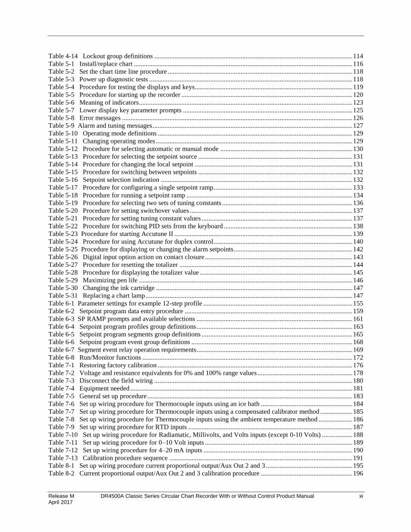
Table 4-14 Lockout group definitions ..................................................................................................................... 114 Table 5-1 Install/replace chart ................................................................................................................................. 116 Table 5-2 Set the chart time line procedure ............................................................................................................. 118 Table 5-3 Power up diagnostic tests ........................................................................................................................ 118 Table 5-4 Procedure for testing the displays and keys............................................................................................. 119 Table 5-5 Procedure for starting up the recorder ..................................................................................................... 120 Table 5-6 Meaning of indicators .............................................................................................................................. 123 Table 5-7 Lower display key parameter prompts .................................................................................................... 125 Table 5-8 Error messages ........................................................................................................................................ 126 Table 5-9 Alarm and tuning messages ...................................................................................................................... 127 Table 5-10 Operating mode definitions ................................................................................................................... 129 Table 5-11 Changing operating modes .................................................................................................................... 129 Table 5-12 Procedure for selecting automatic or manual mode .............................................................................. 130 Table 5-13 Procedure for selecting the setpoint source ........................................................................................... 131 Table 5-14 Procedure for changing the local setpoint ............................................................................................. 131 Table 5-15 Procedure for switching between setpoints ........................................................................................... 132 Table 5-16 Setpoint selection indication ................................................................................................................. 132 Table 5-17 Procedure for configuring a single setpoint ramp.................................................................................. 133 Table 5-18 Procedure for running a setpoint ramp .................................................................................................. 134 Table 5-19 Procedure for selecting two sets of tuning constants ............................................................................. 136 Table 5-20 Procedure for setting switchover values ................................................................................................ 137 Table 5-21 Procedure for setting tuning constant values ......................................................................................... 137 Table 5-22 Procedure for switching PID sets from the keyboard ............................................................................ 138 Table 5-23 Procedure for starting Accutune II ......................................................................................................... 139 Table 5-24 Procedure for using Accutune for duplex control.................................................................................. 140 Table 5-25 Procedure for displaying or changing the alarm setpoints ...................................................................... 142 Table 5-26 Digital input option action on contact closure ....................................................................................... 143 Table 5-27 Procedure for resetting the totalizer ...................................................................................................... 144 Table 5-28 Procedure for displaying the totalizer value .......................................................................................... 145 Table 5-29 Maximizing pen life .............................................................................................................................. 146 Table 5-30 Changing the ink cartridge .................................................................................................................... 147 Table 5-31 Replacing a chart lamp .......................................................................................................................... 147 Table 6-1 Parameter settings for example 12-step profile ........................................................................................ 155 Table 6-2 Setpoint program data entry procedure ................................................................................................... 159 Table 6-3 SP RAMP prompts and available selections ............................................................................................ 161 Table 6-4 Setpoint program profiles group definitions ............................................................................................ 163 Table 6-5 Setpoint program segments group definitions ......................................................................................... 165 Table 6-6 Setpoint program event group definitions ............................................................................................... 168 Table 6-7 Segment event relay operation requirements ............................................................................................ 169 Table 6-8 Run/Monitor functions ............................................................................................................................ 172 Table 7-1 Restoring factory calibration ................................................................................................................... 176 Table 7-2 Voltage and resistance equivalents for 0% and 100% range values ........................................................ 178 Table 7-3 Disconnect the field wiring ..................................................................................................................... 180 Table 7-4 Equipment needed ................................................................................................................................... 181 Table 7-5 General set up procedure ......................................................................................................................... 183 Table 7-6 Set up wiring procedure for Thermocouple inputs using an ice bath ...................................................... 184 Table 7-7 Set up wiring procedure for Thermocouple inputs using a compensated calibrator method ................... 185 Table 7-8 Set up wiring procedure for Thermocouple inputs using the ambient temperature method .................... 186 Table 7-9 Set up wiring procedure for RTD inputs ................................................................................................. 187 Table 7-10 Set up wiring procedure for Radiamatic, Millivolts, and Volts inputs (except 0-10 Volts) .................. 188 Table 7-11 Set up wiring procedure for 0–10 Volt inputs ....................................................................................... 189 Table 7-12 Set up wiring procedure for 4–20 mA inputs ........................................................................................ 190 Table 7-13 Calibration procedure sequence ............................................................................................................ 191 Table 8-1 Set up wiring procedure current proportional output/Aux Out 2 and 3 ................................................... 195 Table 8-2 Current proportional output/Aux Out 2 and 3 calibration procedure ...................................................... 196
xii DR4500A Classic Series Circular Chart Recorder With or Without Control Product Manual Release M April 2017
Table 8-3 Position proportional output calibration procedure ................................................................................. 198 Table 8-4 Set up wiring procedure for auxiliary output ........................................................................................... 200 Table 8-5 Auxiliary output calibration procedure.................................................................................................... 201 Table 9-1 Procedure for identifying the software version ....................................................................................... 205 Table 9-2 Power-up tests ......................................................................................................................................... 206 Table 9-3 Procedure for displaying the device status .............................................................................................. 207 Table 9-4 Error message prompts ............................................................................................................................ 208 Table 9-5 Visual failure symptoms .......................................................................................................................... 212 Table 9-6 Procedure #1—Troubleshooting recorder failure symptoms................................................................... 213 Table 9-7 Procedure #2—Troubleshooting pen trace failure symptoms ................................................................. 214 Table 9-8 Procedure #3—Troubleshooting chart rotation failure symptoms........................................................... 214 Table 9-9 Procedure #4—Troubleshooting erratic pen movement symptoms......................................................... 215 Table 9-10 Procedure #5—Troubleshooting pen failure symptoms ........................................................................ 215 Table 9-11 Procedure #6—Troubleshooting keyboard and/or display failure symptoms ....................................... 215 Table 9-12 Procedure #7—Troubleshooting current proportional output failure symptoms ................................... 216 Table 9-13 Procedure #8—Troubleshooting position proportional output failure symptoms ................................. 216 Table 9-14 Procedure #9—Troubleshooting relay output failure symptoms ........................................................... 217 Table 9-15 Procedure #10—Troubleshooting current/time or time/current failure symptoms ................................ 217 Table 9-16 Procedure #11—Troubleshooting the auxiliary output ......................................................................... 218 Table 9-17 Procedure #12—Troubleshooting external alarm function failure symptoms ....................................... 218 Table 9-18 Procedure #13—Troubleshooting Modbus communications failure symptoms .................................... 218 Table 9-19 Pen 1 (purple) and Pen 2 (red) Mechanical Alignment ......................................................................... 219 Table 9-20 Set the chart time line procedure ........................................................................................................... 221 Table 10-1 Door assembly parts .............................................................................................................................. 223 Table 10-2 Chart plate assembly parts ..................................................................................................................... 225 Table 10-3 Basic recorder parts without options ..................................................................................................... 227 Table 10-4 Recorder parts associated with options ................................................................................................. 229 Table 10-5 Miscellaneous hardware kit ................................................................................................................... 230
Release M DR4500A Classic Series Circular Chart Recorder With or Without Control Product Manual xiii April 2017
Figures
Figure 1-1 Operator interface ...................................................................................................................................... 3 Figure 1-2 Set-up tasks ................................................................................................................................................ 5 Figure 2-1 Model number interpretation ................................................................................................................... 13 Figure 2-2 DR4500A recorder hardware components versus “table” selections ....................................................... 15 Figure 2-3 Overall dimensions .................................................................................................................................. 16 Figure 2-4 How to remove knockouts ....................................................................................................................... 17 Figure 2-5 Mounting Flush in a New Panel Cutout ................................................................................................... 18 Figure 2-6 Mounting in a panel using universal filler kit .......................................................................................... 20 Figure 2-7 Mounting in a panel using Kent Model 105M cutout .............................................................................. 21 Figure 2-8 Panel Mounting Recorder with NEMA4X Door ....................................................................................... 23 Figure 2-9 Pipe Mounting Brackets ........................................................................................................................... 24 Figure 2-10 Mounting flush on a surface (of panel or wall) ...................................................................................... 26 Figure 2-11 Ferrite filter locations and shield wiring (CE Mark) .............................................................................. 30 Figure 2-12 AC line power wiring ............................................................................................................................. 32 Figure 2-13 Thermocouple, RTD, Radiamatic, mV, or 0–5 Vdc input wiring .......................................................... 34 Figure 2-14 4-20 mA input wiring ............................................................................................................................. 36 Figure 2-15 0-10 Volt dc input wiring ....................................................................................................................... 38 Figure 2-16 4-20 mA control output wiring (or Aux Out #2 and #3 wiring) ............................................................. 40 Figure 2-17 Position proportional control output wiring ........................................................................................... 42 Figure 2-18 Relay control output wiring ................................................................................................................... 44 Figure 2-19 Alarm output or digital input wiring ...................................................................................................... 46 Figure 2-20 Alarm outputs #3, 4, 5, and 6 wiring ...................................................................................................... 49 Figure 2-21 RS485 Modbus communications wiring ................................................................................................ 51 Figure 2-22 4-20 mA auxiliary output wiring............................................................................................................ 53 Figure 2-23 S1 lockout switch location ..................................................................................................................... 54 Figure 3-1 DR4500A prompt hierarchy ..................................................................................................................... 56 Figure 5-1 Basic recording components .................................................................................................................. 117 Figure 5-2 Operator interface .................................................................................................................................. 122 Figure 5-3 Deviation bargraph ................................................................................................................................. 124 Figure 6-1 Ramp/Soak profile example .................................................................................................................... 154 Figure 7-1 Location of the input connections on the input boards .......................................................................... 180 Figure 7-2 Location of jumper positions W1/MA and W3 on the input boards ...................................................... 182 Figure 7-3 Calibration set up diagram for Thermocouple inputs using an ice bath ................................................. 184 Figure 7-4 Calibration set up diagram for Thermocouple inputs using a compensated calibrator method.............. 185 Figure 7-5 Calibration set up diagram for Thermocouple inputs using the ambient temperature method ............... 186 Figure 7-6 Calibration set up diagram for RTD inputs ............................................................................................ 187 Figure 7-7 Calibration set up diagram for Radiamatic, Millivolts, and Volts inputs (except 0-10 Volts) ............... 188 Figure 7-8 Calibration set up diagram for 0–10 Volt inputs .................................................................................... 189 Figure 7-9 Calibration set up diagram for 4–20 mA inputs ..................................................................................... 190 Figure 8-1 Test equipment connections for calibrating current proportional output ............................................... 195 Figure 8-2 Test equipment connections for calibrating auxiliary output ................................................................. 200 Figure 9-1 Mechanical Alignment of Pens .............................................................................................................. 220 Figure 10-1 Door assembly ..................................................................................................................................... 223 Figure 10-2 Chart plate assembly ............................................................................................................................ 224 Figure 10-3 Basic recorder components without options ........................................................................................ 226 Figure 10-4 Recorder components associated with options ..................................................................................... 228 Figure 10-5 Internal cabling for DR4500A Classic recorder ................................................................................... 232 Figure 10-6 Internal diagram for DR4500A Classic recorder – options only .......................................................... 233

xiv DR4500A Classic Series Circular Chart Recorder With or Without Control Product Manual Release M April 2017
Release M DR4500A Classic Series Circular Chart Recorder With or Without Control Product Manual April 2017
1
1. Overview
1.1 Introduction
Function
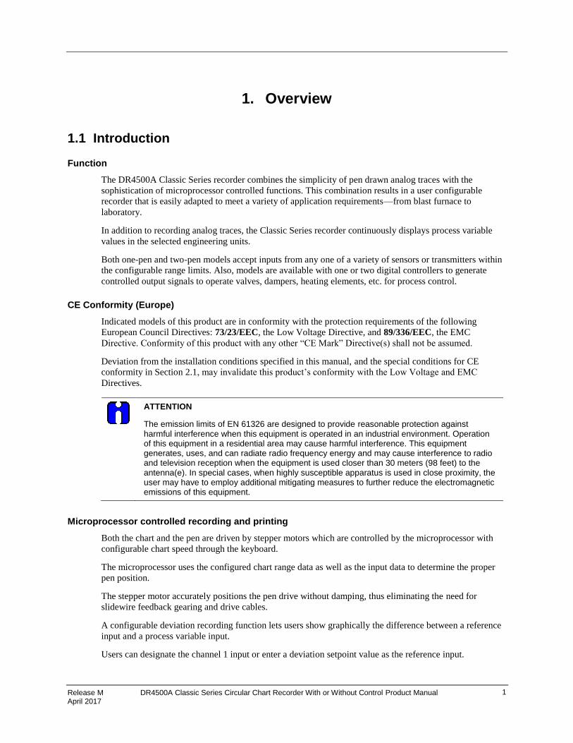
The DR4500A Classic Series recorder combines the simplicity of pen drawn analog traces with the
sophistication of microprocessor controlled functions. This combination results in a user configurable
recorder that is easily adapted to meet a variety of application requirements—from blast furnace to
laboratory.
In addition to recording analog traces, the Classic Series recorder continuously displays process variable
values in the selected engineering units.
Both one-pen and two-pen models accept inputs from any one of a variety of sensors or transmitters within
the configurable range limits. Also, models are available with one or two digital controllers to generate
controlled output signals to operate valves, dampers, heating elements, etc. for process control.
CE Conformity (Europe)
Indicated models of this product are in conformity with the protection requirements of the following
European Council Directives: 73/23/EEC, the Low Voltage Directive, and 89/336/EEC, the EMC
Directive. Conformity of this product with any other “CE Mark” Directive(s) shall not be assumed.
Deviation from the installation conditions specified in this manual, and the special conditions for CE
conformity in Section 2.1, may invalidate this product’s conformity with the Low Voltage and EMC
Directives.
ATTENTION
The emission limits of EN 61326 are designed to provide reasonable protection against harmful interference when this equipment is operated in an industrial environment. Operation of this equipment in a residential area may cause harmful interference. This equipment generates, uses, and can radiate radio frequency energy and may cause interference to radio and television reception when the equipment is used closer than 30 meters (98 feet) to the antenna(e). In special cases, when highly susceptible apparatus is used in close proximity, the user may have to employ additional mitigating measures to further reduce the electromagnetic emissions of this equipment.
Microprocessor controlled recording and printing
Both the chart and the pen are driven by stepper motors which are controlled by the microprocessor with
configurable chart speed through the keyboard.
The microprocessor uses the configured chart range data as well as the input data to determine the proper
pen position.
The stepper motor accurately positions the pen drive without damping, thus eliminating the need for
slidewire feedback gearing and drive cables.
A configurable deviation recording function lets users show graphically the difference between a reference
input and a process variable input.
Users can designate the channel 1 input or enter a deviation setpoint value as the reference input.
Overview Introduction
2 DR4500A Classic Series Circular Chart Recorder With or Without Control Product Manual Release M April 2017
Digital controller
The DR4500A recorder includes an integral microprocessor-based, PID controller with two loops of
control. A variety of output types, including a duplex variation for heat cool applications, lets you select the
output that is right for your final control element.
You can configure the control action as On-Off, PID-A, PID-B, or PD with manual reset. English language
prompts guide you through the entry of all the controller's configurable parameters.
Construction
The DR4500 recorder is housed in a molded case which can be panel or surface mounted. A glass or acrylic
windowed door protects the internal components while allowing easy access to the chart and operator
interface. An optional external keypad that allows operator selections without opening the door is available.
Circuitry is partitioned on printed circuit boards for ease of service.
Power, input, and output wiring connect to terminations inside the case. Knockouts in the sides and bottom
of the case accept conduit connections for convenient wire entry.

Overview Operator Interface
Release M DR4500A Classic Series Circular Chart Recorder With or Without Control Product Manual 3 April 2017
1.2 Operator Interface
Operator interface
Figure 1-1 shows the operator interface and defines the displays and indicators. The function of the keys is
described in Table 1-1.
22074
Control relay
1 or 2 is ON,
when lit.
ALM
CHN
RSP
OUT
12 FC
%RUN
HOLD
MAN
12
Lower Display - eight characters
Normal operation - Displays selectable
operating parameters and values.
Configuration mode - Displays function
group and parameters.
Remote setpoint or
2nd setpoint is
active, when lit.
Blinks when 2nd
setpoint or remote
setpoint is
obtained through
remote switch.
PV displayed is
for channel 1 or 2
Alarm condition
exists for alarm 1
or 2, when lit.
Indicates temperature
units of PV
Upper Display - six characters
Normal operation - Displays process
variable (PV) for selected channel.
Configuration mode - Displays selection or
parameter value.
Indicates controller mode:
MAN = Manual
A = Automatic
Bargraph - deviation (±10% of span)
Center green bar indicates PV is within
±1% of control setpoint.
Next small bar will light if PV is between
±1% but less than ±2% in deviation.
If PV is equal to or greater than ±10%
deviation, the green bar plus all ten small
green bars will light.
12
Key Pad/Key Functions
FUNCLOWR
DISP
MAN
AUTOCHART
SET
UP
Figure 1-1 Operator interface

Overview Operator Interface
4 DR4500A Classic Series Circular Chart Recorder With or Without Control Product Manual Release M April 2017
Key functions
Table 1-1 shows each key on the operator interface and defines its function.
Table 1-1 Function of keys
Key Function
SET UP
Places the controller in the Configuration Set Up group select mode. Sequentially displays Set Up groups and allows the FUNC key to display individual functions in
each Set Up group.
FUNC Used in conjunction with the SET UP key to select the individual functions of a
selected Configuration Set Up group.
Used to toggle between SP1 and SP2.
Used during field calibration procedure.
LOWR DISP
Selects an operating parameter to be shown in the lower display:
OUT = Output Value SP = Local Setpoint 1 SPN = Current setpoint for setpoint rate applications 2SP = Local Setpoint 2 RSP = Remote Setpoint 2IN = Input 2 DEV = Deviation EU = PV Engineering Units RH = % RH Value PIDSETX = Tuning Parameter Set X=1 or 2 RAMP = Minutes remaining in Setpoint Ramp #RA = Minutes remaining in SP Prog Ramp #SK = Minutes remaining in SP Prog Soak RECYC = Number of recycles left in SP Program
= Time remaining in Timer function
= Time elapsed in Timer function TUNExXXX = Accutune II indicator. x = 1 or 2
ATTENTION The lower display can be configured to scroll through the operating parameters.
MAN AUTO
Alternately selects: AUTO Lower display automatically displays setpoint value in engineering units. MAN Lower display automatically indicates output in %.
CHART Used to stop recording operation and move pen to outer limit for chart change.
RUN HOLD
Alternate action switch initiates or holds the Setpoint Ramp or Setpoint Program.
In configuration mode, restores the original value or selection if you do not want to enter a change you are making to a parameter.
Increases the setpoint, output, or configuration values displayed.
Used to step through the items in each function while in configuration mode plus adjust control variables in the lower display.
Decreases the setpoint, output, or configuration values displayed.
Used to step through the items in each function while in configuration mode plus adjust control variables in the lower display.
Overview Set-up Tasks
Release M DR4500A Classic Series Circular Chart Recorder With or Without Control Product Manual 5 April 2017
1.3 Set-up Tasks
Major set-up tasks
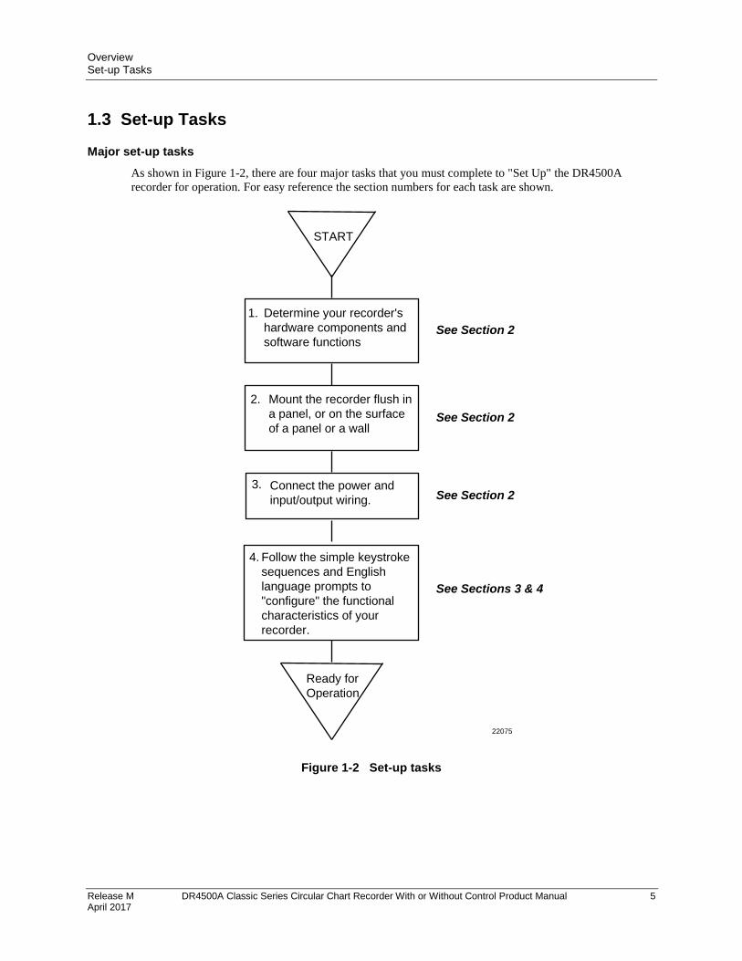
As shown in Figure 1-2, there are four major tasks that you must complete to "Set Up" the DR4500A
recorder for operation. For easy reference the section numbers for each task are shown.
START
Ready for
Operation
1.
2.
4.
3.
Determine your recorder's
hardware components and
software functions
Mount the recorder flush in
a panel, or on the surface
of a panel or a wall
Connect the power and
input/output wiring.
Follow the simple keystroke
sequences and English
language prompts to
"configure" the functional
characteristics of your
recorder.
See Section 2
See Section 2
See Section 2
See Sections 3 & 4
22075
Figure 1-2 Set-up tasks

Overview Set-up Tasks
6 DR4500A Classic Series Circular Chart Recorder With or Without Control Product Manual Release M April 2017
Release M DR4500A Classic Series Circular Chart Recorder With or Without Control Product Manual April 2017
7
2. Installation
2.1 Overview
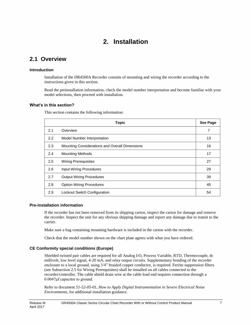
Introduction
Installation of the DR4500A Recorder consists of mounting and wiring the recorder according to the
instructions given in this section.
Read the preinstallation information, check the model number interpretation and become familiar with your
model selections, then proceed with installation.
What’s in this section?
This section contains the following information:
Topic See Page
2.1 Overview 7
2.2 Model Number Interpretation 13
2.3 Mounting Considerations and Overall Dimensions 16
2.4 Mounting Methods 17
2.5 Wiring Prerequisites 27
2.6 Input Wiring Procedures 29
2.7 Output Wiring Procedures 39
2.8 Option Wiring Procedures 45
2.9 Lockout Switch Configuration 54
Pre-installation information
If the recorder has not been removed from its shipping carton, inspect the carton for damage and remove
the recorder. Inspect the unit for any obvious shipping damage and report any damage due to transit to the
carrier.
Make sure a bag containing mounting hardware is included in the carton with the recorder.
Check that the model number shown on the chart plate agrees with what you have ordered.
CE Conformity special conditions (Europe)
Shielded twisted pair cables are required for all Analog I/O, Process Variable, RTD, Thermocouple, dc
millivolt, low level signal, 4-20 mA, and relay output circuits. Supplementary bonding of the recorder
enclosure to a local ground, using 3/4” braided copper conductor, is required. Ferrite suppression filters
(see Subsection 2.5 for Wiring Prerequisites) shall be installed on all cables connected to the
recorder/controller. The cable shield drain wire at the cable load end requires connection through a
0.0047μf capacitor to ground.
Refer to document 51-52-05-01, How to Apply Digital Instrumentation in Severe Electrical Noise
Environments, for additional installation guidance.

Installation - Overview
8 DR4500A Classic Series Circular Chart Recorder With or Without Control Product Manual Release M April 2017
Operating limits and condensed specifications
We recommend that you review and adhere to the operating limits listed in Table 2-1 when you install your
recorder.
Table 2-1 Operating limits and condensed specifications
Condition Specifications
Ambient Temperature 32 to 131°F (0 to 55°C)
Relative Humidity 5 to 90% RH at 40°C (104°F)
Vibration
Frequency Acceleration
0 to 200 Hz 0.2g
Mechanical Shock
Acceleration Duration
5g 30 ms
Power 102 to 132 Vac 50/60 Hz 204 to 264 Vac 50/60 Hz
Power Consumption 20 watts maximum
Digital Indication Accuracy
1 digit
Minimum Input Span Range is fully configurable with span limitation of the operating range selected.
Input Impedance 4-20 mA dc: 250 ohms 0-10 Vdc: 200K ohms All others: 10 Megohms
Source Impedance RTD: 100 ohms per lead maximum
Span Step Response Time
6 seconds maximum with no filtering
Sampling Rate Each input sampled 3 times a second
Input Filter Software: Single pole low pass section with selectable time constants (off to 120 seconds).
Digital Displays Vacuum fluorescent, alphanumeric. A six digit display dedicated to the process variable. Alternate information displayed during configuration mode. An eight digit display shows key selected operating parameters. Also provides guidance during configuration.
Indicators Channel PV display (CHN 1 or 2) Alarm status (ALM 1, 2) Controller Output (OUT 1, 2) Remote Setpoint (RSP) Temperature unit (F or C) or Engineering Units Controller’s mode (A or MAN)
Deviation Bargraph 21 segment, color coded deviation bargraph: Green (large) = On Control Green (small) = Deviation to ±10% of PV
Controller Modes of Operation
Manual Operation Automatic with local setpoint Automatic with remote setpoint
Installation - Overview
Release M DR4500A Classic Series Circular Chart Recorder With or Without Control Product Manual 9 April 2017
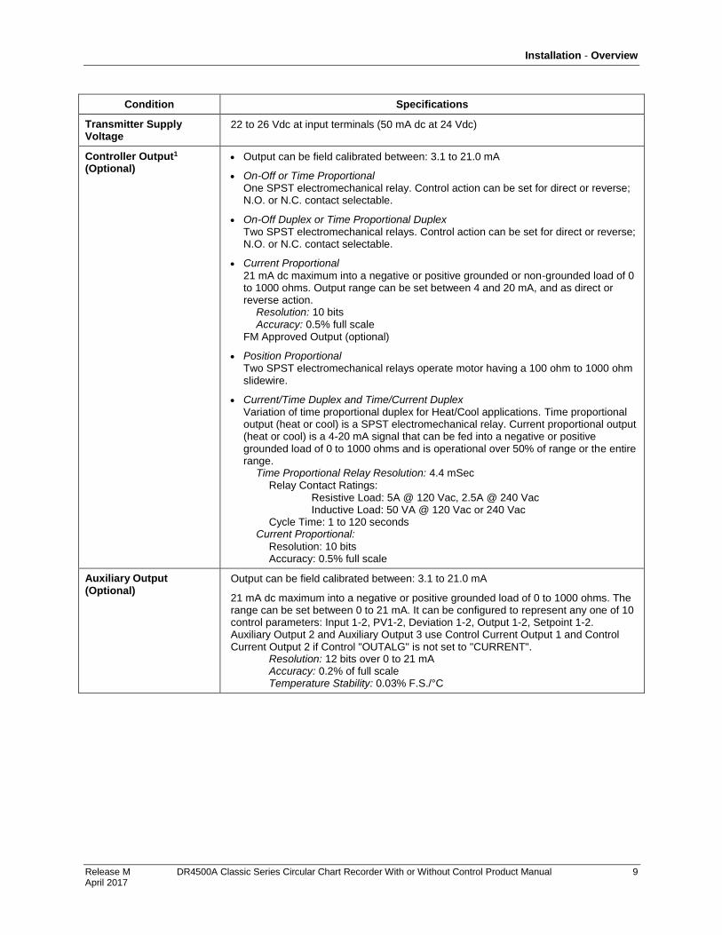
Condition Specifications
Transmitter Supply Voltage
22 to 26 Vdc at input terminals (50 mA dc at 24 Vdc)
Controller Output1 (Optional)
Output can be field calibrated between: 3.1 to 21.0 mA
On-Off or Time Proportional One SPST electromechanical relay. Control action can be set for direct or reverse; N.O. or N.C. contact selectable.
On-Off Duplex or Time Proportional Duplex Two SPST electromechanical relays. Control action can be set for direct or reverse; N.O. or N.C. contact selectable.
Current Proportional
21 mA dc maximum into a negative or positive grounded or non-grounded load of 0 to 1000 ohms. Output range can be set between 4 and 20 mA, and as direct or reverse action. Resolution: 10 bits Accuracy: 0.5% full scale FM Approved Output (optional)
Position Proportional Two SPST electromechanical relays operate motor having a 100 ohm to 1000 ohm slidewire.
Current/Time Duplex and Time/Current Duplex Variation of time proportional duplex for Heat/Cool applications. Time proportional output (heat or cool) is a SPST electromechanical relay. Current proportional output (heat or cool) is a 4-20 mA signal that can be fed into a negative or positive grounded load of 0 to 1000 ohms and is operational over 50% of range or the entire range. Time Proportional Relay Resolution: 4.4 mSec Relay Contact Ratings: Resistive Load: 5A @ 120 Vac, 2.5A @ 240 Vac Inductive Load: 50 VA @ 120 Vac or 240 Vac Cycle Time: 1 to 120 seconds Current Proportional:
Resolution: 10 bits Accuracy: 0.5% full scale
Auxiliary Output (Optional)
Output can be field calibrated between: 3.1 to 21.0 mA
21 mA dc maximum into a negative or positive grounded load of 0 to 1000 ohms. The range can be set between 0 to 21 mA. It can be configured to represent any one of 10 control parameters: Input 1-2, PV1-2, Deviation 1-2, Output 1-2, Setpoint 1-2. Auxiliary Output 2 and Auxiliary Output 3 use Control Current Output 1 and Control Current Output 2 if Control "OUTALG" is not set to "CURRENT". Resolution: 12 bits over 0 to 21 mA Accuracy: 0.2% of full scale Temperature Stability: 0.03% F.S./°C
Installation - Overview
10 DR4500A Classic Series Circular Chart Recorder With or Without Control Product Manual Release M April 2017
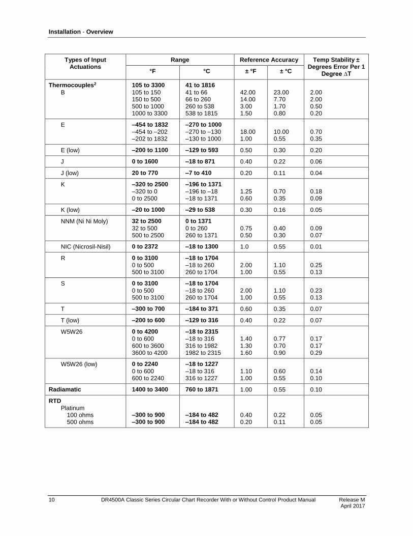
Types of Input Actuations
Range Reference Accuracy Temp Stability ± Degrees Error Per 1
Degree ∆T °F °C ± °F ± °C
Thermocouples2
B
105 to 3300
105 to 150 150 to 500 500 to 1000 1000 to 3300
41 to 1816
41 to 66 66 to 260 260 to 538 538 to 1815
42.00 14.00 3.00 1.50
23.00 7.70 1.70 0.80
2.00 2.00 0.50 0.20
E –454 to 1832
–454 to –202 –202 to 1832
–270 to 1000
–270 to –130 –130 to 1000
18.00 1.00
10.00 0.55
0.70 0.35
E (low) –200 to 1100 –129 to 593 0.50 0.30 0.20
J 0 to 1600 –18 to 871 0.40 0.22 0.06
J (low) 20 to 770 –7 to 410 0.20 0.11 0.04
K –320 to 2500
–320 to 0 0 to 2500
–196 to 1371
–196 to –18 –18 to 1371
1.25 0.60
0.70 0.35
0.18 0.09
K (low) –20 to 1000 –29 to 538 0.30 0.16 0.05
NNM (Ni Ni Moly) 32 to 2500
32 to 500 500 to 2500
0 to 1371
0 to 260 260 to 1371
0.75 0.50
0.40 0.30
0.09 0.07
NIC (Nicrosil-Nisil) 0 to 2372 –18 to 1300 1.0 0.55 0.01
R 0 to 3100
0 to 500 500 to 3100
–18 to 1704
–18 to 260 260 to 1704
2.00 1.00
1.10 0.55
0.25 0.13
S 0 to 3100
0 to 500 500 to 3100
–18 to 1704
–18 to 260 260 to 1704
2.00 1.00
1.10 0.55
0.23 0.13
T –300 to 700 –184 to 371 0.60 0.35 0.07
T (low) –200 to 600 –129 to 316 0.40 0.22 0.07
W5W26 0 to 4200
0 to 600 600 to 3600 3600 to 4200
–18 to 2315
–18 to 316 316 to 1982 1982 to 2315
1.40 1.30 1.60
0.77 0.70 0.90
0.17 0.17 0.29
W5W26 (low) 0 to 2240
0 to 600 600 to 2240
–18 to 1227
–18 to 316 316 to 1227
1.10 1.00
0.60 0.55
0.14 0.10
Radiamatic 1400 to 3400 760 to 1871 1.00 0.55 0.10
RTD
Platinum 100 ohms 500 ohms
–300 to 900 –300 to 900
–184 to 482 –184 to 482
0.40 0.20
0.22 0.11
0.05 0.05

Installation - Overview
Release M DR4500A Classic Series Circular Chart Recorder With or Without Control Product Manual 11 April 2017
Types of Input Actuations
Range Reference Accuracy Temp Stability ± Degrees Error Per 1
Degree ∆T °F °C ± °F ± °C
Linear
Milliamperes dc
Millivolts dc
Volts dc
4 to 20
0 to 10 10 to 50
1 to 5 (can be calibrated 0 to 5) 0 to 10
—
—
— —
0.10%
0.05% 0.05%
0.05% 0.10%
—
—
— —
0.004%/°F
0.004%/°F 0.004%/°F
0.004%/°F 0.004%/°F
Relative Humidity
Platinum 100 ohm Wet/Dry Bulb*
Wet/Dry Input
–130 to 392
–90 to 200
0.30
0.03
0.03
%RH3
Measured %RH
Dry Bulb Range Reference Accuracy
Temp. Stability 53 to 104°F/12 to
40°C °F °C
0 to <20 20 to 100
–103 to 212 35 to 40 >40 to 100 100 to 212
–75 to 100 2 to 4 >4 to 38 38 to 100
2% RH 2% RH 1% RH 1% RH
0.11% RH/°F 0.11%RH/°F 0.06% RH/°F 0.03% RH/°F
Condition Specifications
Case Molded, foamed-Noryl** with gasketed door. A UL and FM approved NEMA4X door is also available.
Pen Disposable fiber-tip ink cartridge. line length per cartridge more than 1000 ft. (305 m). One pen: Purple Two pens: Purple and red
Chart 12-inch (304.8 mm) diameter chart with standard preprinted markings and a calibrated width of 4.62 inches (117.5 mm)
Wiring Connections Terminals inside the case.
Color Case: Black Door (standard): Caribbean Blue, Black, or Gray
Approval Bodies U.L. approval depending on model. CSA approval. Consult Model Selection Guide for information. FM approved for Class I, Div. 2, Groups A, B, C, D areas depending on model.
Weight 13.2 lbs (6 kg)
Mounting Panel, pipe, or surface mounted. Some adapter kits available for existing panel cutouts.
OPTIONS
Alarm Output Two, four, or six relays available. Relays 3 through 6 available if not used for control outputs. Relay Contact Ratings: First Relays, Resistive Load: 1A @ 120 Vac, 1/2A @ 240 Vac Relays 3 through 6, Resistive Load: 5A @ 120 Vac, 2.5A @ 240 Vac
Digital Input +20 Vdc source for external dry contact or isolated solid state contacts. Selects one configured input.
Totalizers One or two totalizers depending on model. Eight digit “totals” with multiplier on digital display.
Installation - Overview
12 DR4500A Classic Series Circular Chart Recorder With or Without Control Product Manual Release M April 2017
Condition Specifications
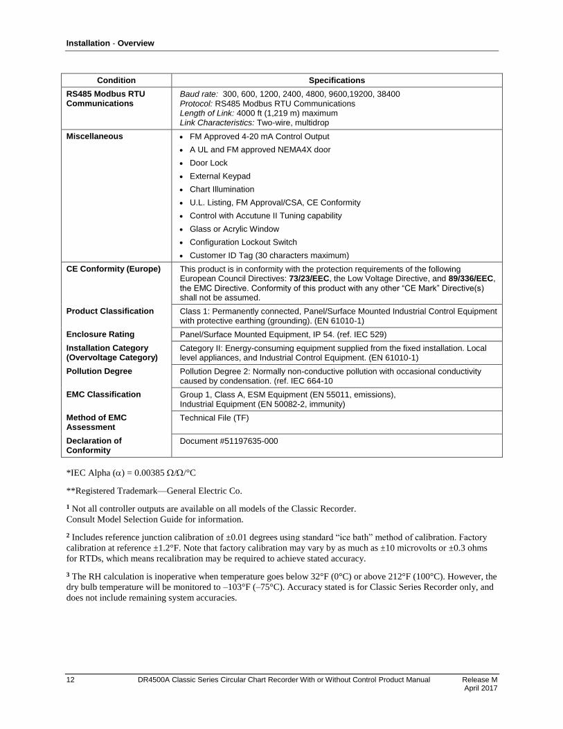
RS485 Modbus RTU Communications
Baud rate: 300, 600, 1200, 2400, 4800, 9600,19200, 38400 Protocol: RS485 Modbus RTU Communications Length of Link: 4000 ft (1,219 m) maximum Link Characteristics: Two-wire, multidrop
Miscellaneous FM Approved 4-20 mA Control Output
A UL and FM approved NEMA4X door
Door Lock
External Keypad
Chart Illumination
U.L. Listing, FM Approval/CSA, CE Conformity
Control with Accutune II Tuning capability
Glass or Acrylic Window
Configuration Lockout Switch
Customer ID Tag (30 characters maximum)
CE Conformity (Europe) This product is in conformity with the protection requirements of the following European Council Directives: 73/23/EEC, the Low Voltage Directive, and 89/336/EEC,
the EMC Directive. Conformity of this product with any other “CE Mark” Directive(s) shall not be assumed.
Product Classification Class 1: Permanently connected, Panel/Surface Mounted Industrial Control Equipment with protective earthing (grounding). (EN 61010-1)
Enclosure Rating Panel/Surface Mounted Equipment, IP 54. (ref. IEC 529)
Installation Category (Overvoltage Category)
Category II: Energy-consuming equipment supplied from the fixed installation. Local level appliances, and Industrial Control Equipment. (EN 61010-1)
Pollution Degree Pollution Degree 2: Normally non-conductive pollution with occasional conductivity caused by condensation. (ref. IEC 664-10
EMC Classification Group 1, Class A, ESM Equipment (EN 55011, emissions), Industrial Equipment (EN 50082-2, immunity)
Method of EMC Assessment
Technical File (TF)
Declaration of Conformity
Document #51197635-000
*IEC Alpha () = 0.00385 //°C
**Registered Trademark—General Electric Co.
1 Not all controller outputs are available on all models of the Classic Recorder.
Consult Model Selection Guide for information.
2 Includes reference junction calibration of ±0.01 degrees using standard “ice bath” method of calibration. Factory
calibration at reference ±1.2°F. Note that factory calibration may vary by as much as ±10 microvolts or ±0.3 ohms
for RTDs, which means recalibration may be required to achieve stated accuracy.
3 The RH calculation is inoperative when temperature goes below 32°F (0°C) or above 212°F (100°C). However, the
dry bulb temperature will be monitored to –103°F (–75°C). Accuracy stated is for Classic Series Recorder only, and
does not include remaining system accuracies.
Installation - Model Number Interpretation
Release M DR4500A Classic Series Circular Chart Recorder With or Without Control Product Manual 13 April 2017
2.2 Model Number Interpretation
Model number
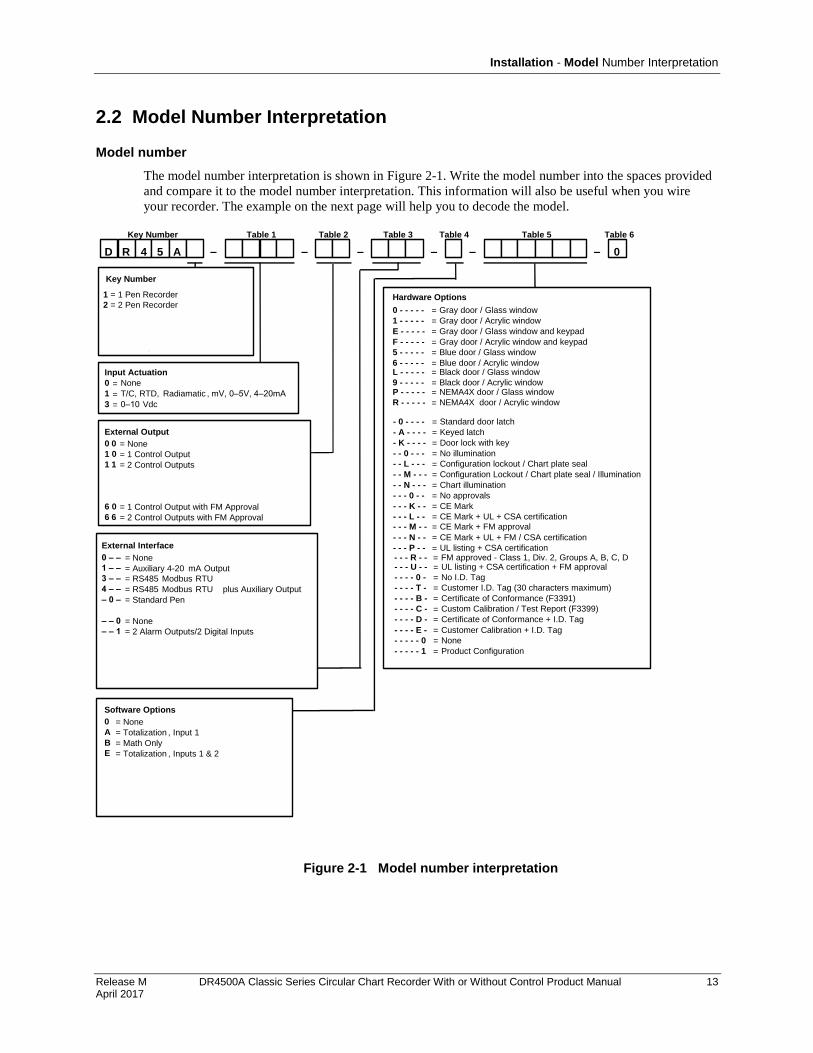
The model number interpretation is shown in Figure 2-1. Write the model number into the spaces provided
and compare it to the model number interpretation. This information will also be useful when you wire
your recorder. The example on the next page will help you to decode the model.
Figure 2-1 Model number interpretation
Input Actuation (Note 1)
D R 4 5 A 00
0
1
3
=
=
=
None
T/C, RTD, Radiamatic , mV, 0–5V, 4–20mA
0–10 Vdc
External Output
0 0
1 0
1 1
4 0
4 4
5 0
6 0
6 6
= None
= 1 Control Output
= 2 Control Outputs
= 1 Control w/SP Programming
= 2 Controls w/SP Programming
= Pulse Output
= 1 Control Output with FM Approval
= 2 Control Outputs with FM Approval
Table 1 Table 2 Table 3 Table 4 Table 5Key Number
Hardware Options
0 - - - - -
1 - - - - -
E - - - - -
F - - - - -
5 - - - - -
6 - - - - -
Software Options
0
A
B
E
F
H
K
L
M
= None
= Totalization , Input 1
= Math Only
= Totalization , Inputs 1 & 2
= Fo Sterilization Calculation
= Totalization , Inputs 1, 2, 3, & 4
= Totalization , Input 1 + Math
= Totalization , Input 1 and 2 + Math
= Totalization , Input 1, 2, 3, 4 + Math
– – – – – –
Table 6
Key Number
T
R
W
H
P
S
=
=
=
=
=
=
Standard Recorder
Relay expansion Recorder
Flow Recorder
HTST
Pasteurization Recorder - Flow
Safety Thermal Limit Recorder
NOTE 1:
Every DR4500A recorder has all the available inputactuations stored in its nonvolatile memory
and can accept up to 4 inputs which must be specified sequentially in 1–4 entries in Table 1.
Therefore, you can easily change the input actuation in the field by re-wiring input connections,
changing the input jumper position, and reconfiguring the input type, as applicable.
Gray door / Glass window
Gray door / Acrylic window
Gray door / Glass window and keypad
Gray door / Acrylic window and keypad
Blue door / Glass window
Blue door / Acrylic window
External Interface
0 – –
1 – –
3 – –
4 – –
– 0 –
– 1 –
– – 0
– – 1
– – 2
– – 3
– – 4
= None
= Auxiliary 4-20 mA Output
= RS485 Modbus RTU**
= RS485 Modbus RTU** plus Auxiliary Output
= Standard Pen
= Abrasion Resistant Pen
= None
= 2 Alarm Outputs/2 Digital Inputs
= 4 Alarm Outputs/2 Digital Inputs
= 6 Alarm Outputs/2 Digital Inputs
= 1 Alarm/1 Timer/2 Digital Inputs **
**Only available with key number DR45AT, AR, AW
=
=
=
=
=
=L - - - - -
9 - - - - -
Black door / Glass window
Black door / Acrylic window
=
=P - - - - -
R - - - - -
S - - - - -
NEMA4X door / Glass window
NEMA4X door / Acrylic window
NEMA4X HTST door
=
=
=- 0 - - - -
- A - - - -
- K - - - -
- - 0 - - -
- - L - - -
- - M - - -
- - N - - -
- - - 0 - -
- - - K - -
- - - L - -
- - - M - -
- - - N - -
- - - P - -
Standard door latch
Keyed latch
Door lock with key
No illumination
Configuration lockout / Chart plate seal
Configuration Lockout / Chart plate seal / Illumination
Chart illumination
No approvals
CE Mark
CE Mark + UL + CSA certification
CE Mark + FM approval
CE Mark + UL + FM / CSA certification
UL listing + CSA certification
=
=
=
=
=
=
=
=
=
=
=
=
=- - - R - - FM approved - Class 1, Div. 2, Groups A, B, C, D=- - - U - -
- - - - 0 -
- - - - T -
- - - - B -
- - - - C -
- - - - D -
- - - - E -
- - - - - 0
- - - - - 1
UL listing + CSA certification + FM approval
No I.D. Tag
Customer I.D. Tag (30 characters maximum)
Certificate of Conformance (F3391)
Custom Calibration / Test Report (F3399)
Certificate of Conformance + I.D. Tag
Customer Calibration + I.D. Tag
None
Product Configuration
=
=
=
=
=
=
=
=
=
1 = 1 Pen Recorder
2 = 2 Pen Recorder
Installation - Model Number Interpretation
14 DR4500A Classic Series Circular Chart Recorder With or Without Control Product Manual Release M April 2017
Example of model number decoding
Assume that the model number on the label is
DR45A2 - 1300 - 10 - 001 - A - 1KN0T0 - 0
Using the table code definitions from Figure 2-1, this recorder has the following features and options:
2-input type with thermocouple, RTD, Radiamatic, mV, 0-5 Vdc or 4-20 mA input for channel 1
0-10 Vdc input for channel 2
One controller output
Alarm output / digital input capability
Totalization for input 1
Gray door with acrylic window
Door lock
No approvals
Chart illumination
Customer I.D. tag
Location of hardware components
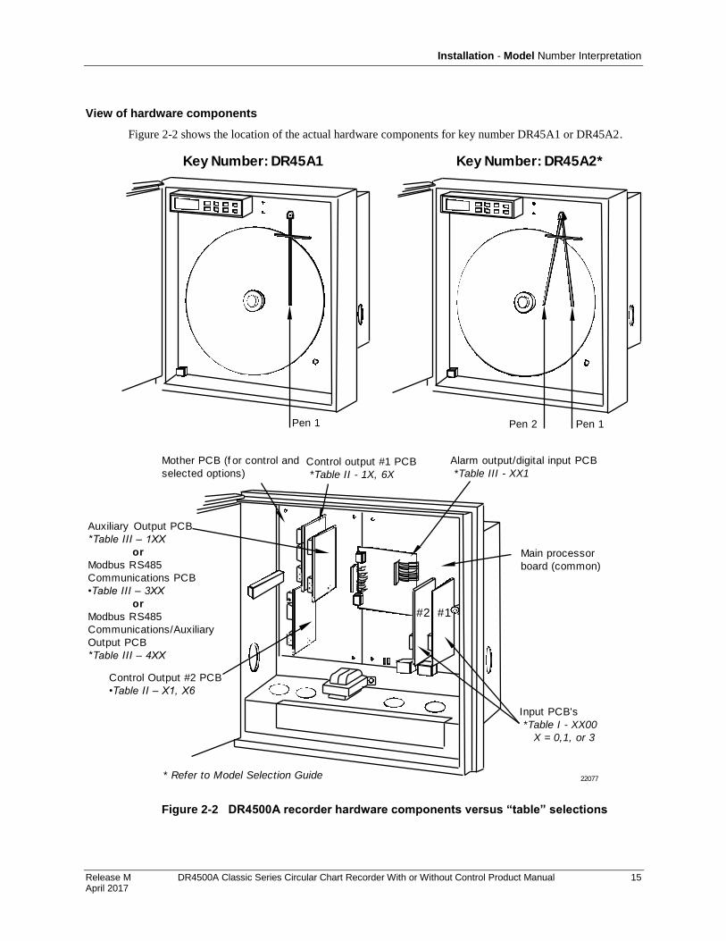
After you decode your recorder’s model number, refer to Figure 2-2 to match “table” selections with the
location of actual recorder hardware components. This will help you to determine applicable input / output
wiring requirements, as well as identify appropriate software functions to be configured later.
To access and view the actual components inside your recorder, follow the procedure in Table 2-2.
Table 2-2 Procedure to access components
Step Action
1 Turn the latch on the recorder door and swing the door open.
2 Loosen the captive screw on the right hand side of the chart plate and swing the chart plate out.
3 Reverse the steps to close the chart plate and door.
Installation - Model Number Interpretation
Release M DR4500A Classic Series Circular Chart Recorder With or Without Control Product Manual 15 April 2017
View of hardware components
Figure 2-2 shows the location of the actual hardware components for key number DR45A1 or DR45A2.
Key Number: DR45A1
Main processor
board (common)
#2 #1
Input PCB's
*Table I - XX00
X = 0,1, or 3
Alarm output/digital input PCB
*Table III - XX1Control output #1 PCB
*Table II - 1X, 6X
Mother PCB (f or control and
selected options)
22077* Refer to Model Selection Guide
Key Number: DR45A2*
Pen 1 Pen 1Pen 2
Auxiliary Output PCB
*Table III – 1XX
or
Modbus RS485
Communications PCB
•Table III – 3XX
or
Modbus RS485
Communications/Auxiliary
Output PCB
*Table III – 4XX
Control Output #2 PCB
•Table II – X1, X6
Figure 2-2 DR4500A recorder hardware components versus “table” selections
Installation - Mounting Considerations and Overall Dimensions
16 DR4500A Classic Series Circular Chart Recorder With or Without Control Product Manual Release M April 2017
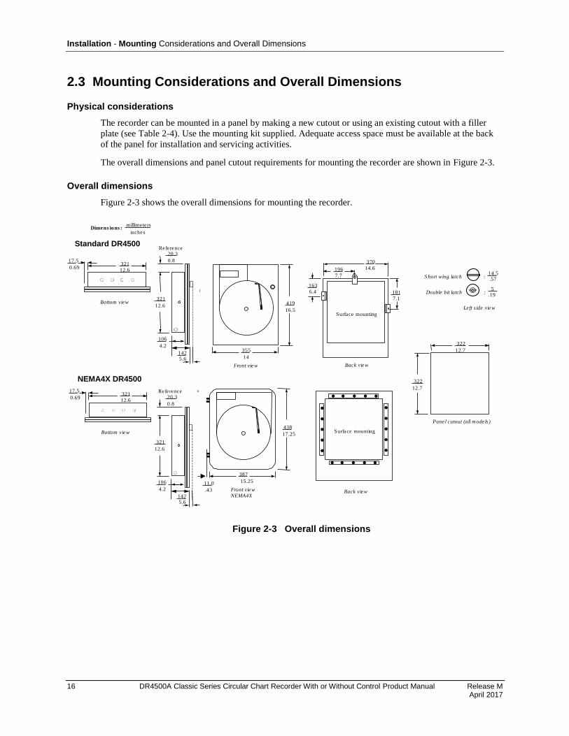
2.3 Mounting Considerations and Overall Dimensions
Physical considerations
The recorder can be mounted in a panel by making a new cutout or using an existing cutout with a filler
plate (see Table 2-4). Use the mounting kit supplied. Adequate access space must be available at the back
of the panel for installation and servicing activities.
The overall dimensions and panel cutout requirements for mounting the recorder are shown in Figure 2-3.
Overall dimensions
Figure 2-3 shows the overall dimensions for mounting the recorder.
321
12.6
17.5
0.69
Bottom view
355
14
419
16.5
Front view
322
12.7
322
12.7
Panel cutout (all mode ls )
163
6.4
196
7.7
370
14.6
181
7.1
Surface mounting
Back view
Dimens ions :millimete rs
inches
Left s ide view
14.5.57
S hort wing latch :
5.19
Double bit latch :
321
12.6
1425.6
106
4.2
Reference20.3
0.8
387
15.25
438
17.25
Front view
NEMA4X
Standard DR4500
NEMA4X DR4500
321
12.6
17.5
0.69
Bottom view
321
12.6
1425.6
106
4.2
Reference20.3
0.8
Surface mounting
Back view
11.0
.43
Figure 2-3 Overall dimensions
Installation - Mounting Methods
Release M DR4500A Classic Series Circular Chart Recorder With or Without Control Product Manual 17 April 2017
2.4 Mounting Methods
Introduction
There are several methods available for mounting your recorder. They are:
Flush in Panel (new panel cutout)
Flush in Panel (using an existing panel cutout)
using universal filler plate kit
using cutout made for Kent Model 105M
Flush in Panel for recorders with NEMA4 Door
On a 2-inch Pipe
On Surface (of panel or wall)
Procedures for each method follow. Choose the one that meets your mounting requirements. Use the
associated dimension drawings for reference.
How to remove knockouts for conduits
Before you mount the recorder, remove the appropriate “knockouts” in the bottom and/or sides of the
recorder case for wire entry via 1/2" (12.7mm) conduits. Refer to Figure 2-4 for knockout locations.
ATTENTION
The knockouts are really plugs that you just have to push out to remove.
21405
Side View
Bottom View
Figure 2-4 How to remove knockouts

Installation - Mounting Methods
18 DR4500A Classic Series Circular Chart Recorder With or Without Control Product Manual Release M April 2017
Mounting flush in panel (New panel cutout)
Refer to Figure 2-5 and follow the procedure in Table 2-3 to make a new cutout in a panel and mount your
recorder in the cutout.
Table 2-3 Mounting flush in a new panel cutout
Step Action
1 At the appropriate location, make a square cutout in the panel measuring 12.7 ±0.060 inches by 12.7 ±0.060 inches (322.58 ±1.52 by 322.58 ±1.52 millimeters). See Figure 2-3.
2 Orient the recorder case properly and slide it into the cutout from the front of the panel. Support the recorder as shown in steps 3 and 4.
3 Refer to Figure 2-5. From the back of the panel, attach a mounting bracket to each side of the recorder case using a 1/4-20 x 1/2 inch hex screw and a lockwasher for each bracket (mounting hardware supplied with recorder). Leave the screws slightly loose so you can adjust the brackets.
4 While holding the recorder firmly against the panel, slide each bracket against the back of the panel and tighten the screws.
Hex screw,
1/4-20 x
1/2 inch and
washer 21406
Figure 2-5 Mounting Flush in a New Panel Cutout
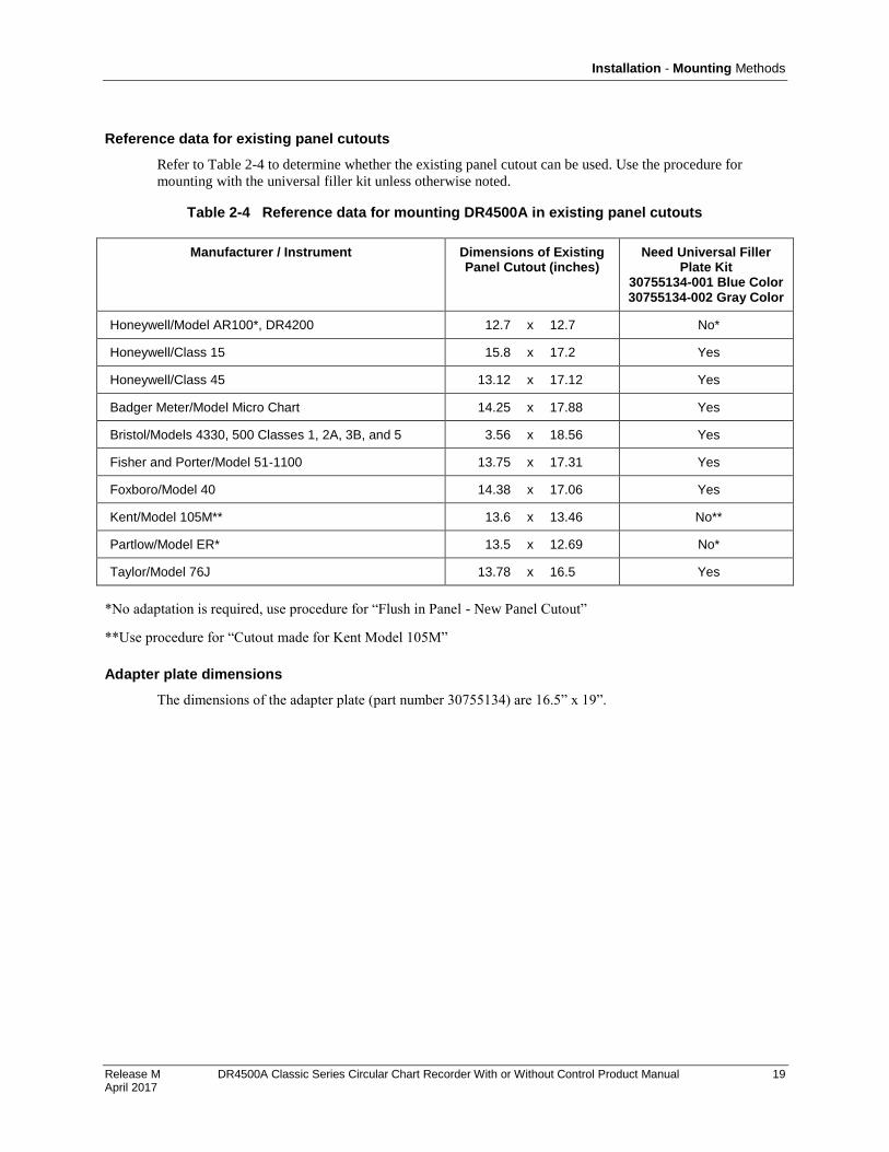
Installation - Mounting Methods
Release M DR4500A Classic Series Circular Chart Recorder With or Without Control Product Manual 19 April 2017
Reference data for existing panel cutouts
Refer to Table 2-4 to determine whether the existing panel cutout can be used. Use the procedure for
mounting with the universal filler kit unless otherwise noted.
Table 2-4 Reference data for mounting DR4500A in existing panel cutouts
Manufacturer / Instrument Dimensions of Existing Panel Cutout (inches)
Need Universal Filler Plate Kit
30755134-001 Blue Color 30755134-002 Gray Color
Honeywell/Model AR100*, DR4200 12.7 x 12.7 No*
Honeywell/Class 15 15.8 x 17.2 Yes
Honeywell/Class 45 13.12 x 17.12 Yes
Badger Meter/Model Micro Chart 14.25 x 17.88 Yes
Bristol/Models 4330, 500 Classes 1, 2A, 3B, and 5 3.56 x 18.56 Yes
Fisher and Porter/Model 51-1100 13.75 x 17.31 Yes
Foxboro/Model 40 14.38 x 17.06 Yes
Kent/Model 105M** 13.6 x 13.46 No**
Partlow/Model ER* 13.5 x 12.69 No*
Taylor/Model 76J 13.78 x 16.5 Yes
*No adaptation is required, use procedure for “Flush in Panel - New Panel Cutout”
**Use procedure for “Cutout made for Kent Model 105M”
Adapter plate dimensions
The dimensions of the adapter plate (part number 30755134) are 16.5” x 19”.

Installation - Mounting Methods
20 DR4500A Classic Series Circular Chart Recorder With or Without Control Product Manual Release M April 2017
Mounting flush in panel (using universal filler plate kit)
Refer to Figure 2-6 and follow the procedure in Table 2-5 to mount your recorder in an existing cutout
using the Universal Filler Kit.
Table 2-5 Mounting flush in a panel using universal filler kit
Step Action
1 Lay the recorder face down on a clean work surface and position the universal filler plate as shown in Figure 2-6.
2 Measure the height of the existing panel cutout.
3 Refer to Figure 2-6. Position the support brackets, supplied with the kit, so that the distance from the top of the “window” in the filler plate to the right angle of the support brackets is just less than the height of the existing panel cutout.
4 Secure brackets with two 10-32 x 1/4 inch screws, provided in the kit, by inserting them through the holes in the filler plate into the tapped screw holes in the recorder case.
5 Insert the recorder into the cutout from the front of the panel as shown in Figure 2-6.
6 Refer to Figure 2-6. From the back of the panel attach a mounting bracket to each side of the recorder case using a 1/4-20 x 1/2-inch hex screw and a lockwasher for each bracket (mounting hardware supplied with recorder). Leave the screws slightly loose so you can adjust the brackets.
7 While holding the recorder firmly against the panel, slide each bracket against the back of the panel and tighten the screws.
Universal
fi l ler plate
Height
of
cutout
in
panel
Tapped
screw holes
Support
brackets
Universal
fi l ler plate
21407
Support brackets
(included in kit 30755134-xxxMounting brackets (supplied
with recorder)
NOTE: Universal fi l ler plate and attaching
hardware are included in kit 30755134-xxx
Figure 2-6 Mounting in a panel using universal filler kit
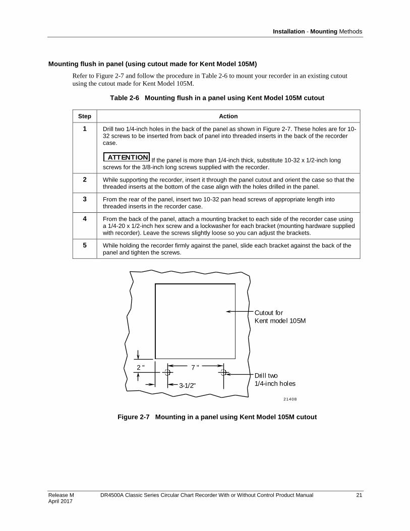
Installation - Mounting Methods
Release M DR4500A Classic Series Circular Chart Recorder With or Without Control Product Manual 21 April 2017
Mounting flush in panel (using cutout made for Kent Model 105M)
Refer to Figure 2-7 and follow the procedure in Table 2-6 to mount your recorder in an existing cutout
using the cutout made for Kent Model 105M.
Table 2-6 Mounting flush in a panel using Kent Model 105M cutout
Step Action
1 Drill two 1/4-inch holes in the back of the panel as shown in Figure 2-7. These holes are for 10-32 screws to be inserted from back of panel into threaded inserts in the back of the recorder case.
ATTENTION If the panel is more than 1/4-inch thick, substitute 10-32 x 1/2-inch long screws for the 3/8-inch long screws supplied with the recorder.
2 While supporting the recorder, insert it through the panel cutout and orient the case so that the threaded inserts at the bottom of the case align with the holes drilled in the panel.
3 From the rear of the panel, insert two 10-32 pan head screws of appropriate length into threaded inserts in the recorder case.
4 From the back of the panel, attach a mounting bracket to each side of the recorder case using a 1/4-20 x 1/2-inch hex screw and a lockwasher for each bracket (mounting hardware supplied with recorder). Leave the screws slightly loose so you can adjust the brackets.
5 While holding the recorder firmly against the panel, slide each bracket against the back of the panel and tighten the screws.
21408
7 "
3-1/2"
2 "
Dril l two
1/4-inch holes
Cutout for
Kent model 105M
Figure 2-7 Mounting in a panel using Kent Model 105M cutout
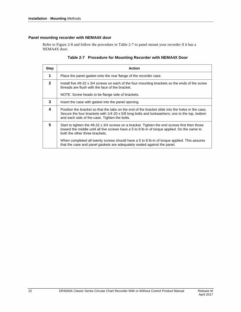
Installation - Mounting Methods
22 DR4500A Classic Series Circular Chart Recorder With or Without Control Product Manual Release M April 2017
Panel mounting recorder with NEMA4X door
Refer to Figure 2-8 and follow the procedure in Table 2-7 to panel mount your recorder if it has a
NEMA4X door.
Table 2-7 Procedure for Mounting Recorder with NEMA4X Door
Step Action
1 Place the panel gasket onto the rear flange of the recorder case.
2 Install five #8-32 x 3/4 screws on each of the four mounting brackets so the ends of the screw threads are flush with the face of the bracket.
NOTE: Screw heads to be flange side of brackets.
3 Insert the case with gasket into the panel opening.
4 Position the bracket so that the tabs on the end of the bracket slide into the holes in the case, Secure the four brackets with 1/4-20 x 5/8 long bolts and lockwashers; one to the top, bottom and each side of the case. Tighten the bolts.
5 Start to tighten the #8-32 x 3/4 screws on a bracket. Tighten the end screws first then those toward the middle until all five screws have a 5 to 8 lb-in of torque applied. Do the same to both the other three brackets.
When completed all twenty screws should have a 5 to 8 lb-in of torque applied. This assures that the case and panel gaskets are adequately sealed against the panel.
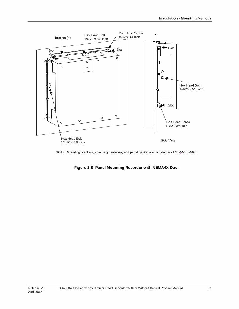
Installation - Mounting Methods
Release M DR4500A Classic Series Circular Chart Recorder With or Without Control Product Manual 23 April 2017
Pan Head Screw
8-32 x 3/4 inch
Hex Head Bolt
1/4-20 x 5/8 inch
Hex Head Bolt
1/4-20 x 5/8 inchBracket (4)
Side View
NOTE: Mounting brackets, attaching hardware, and panel gasket are included in kit 30755065-503;
Slot Slot
8-32 x 3/4 inch
Pan Head Screw
Hex Head Bolt
1/4-20 x 5/8 inch
Slot
Slot
Figure 2-8 Panel Mounting Recorder with NEMA4X Door
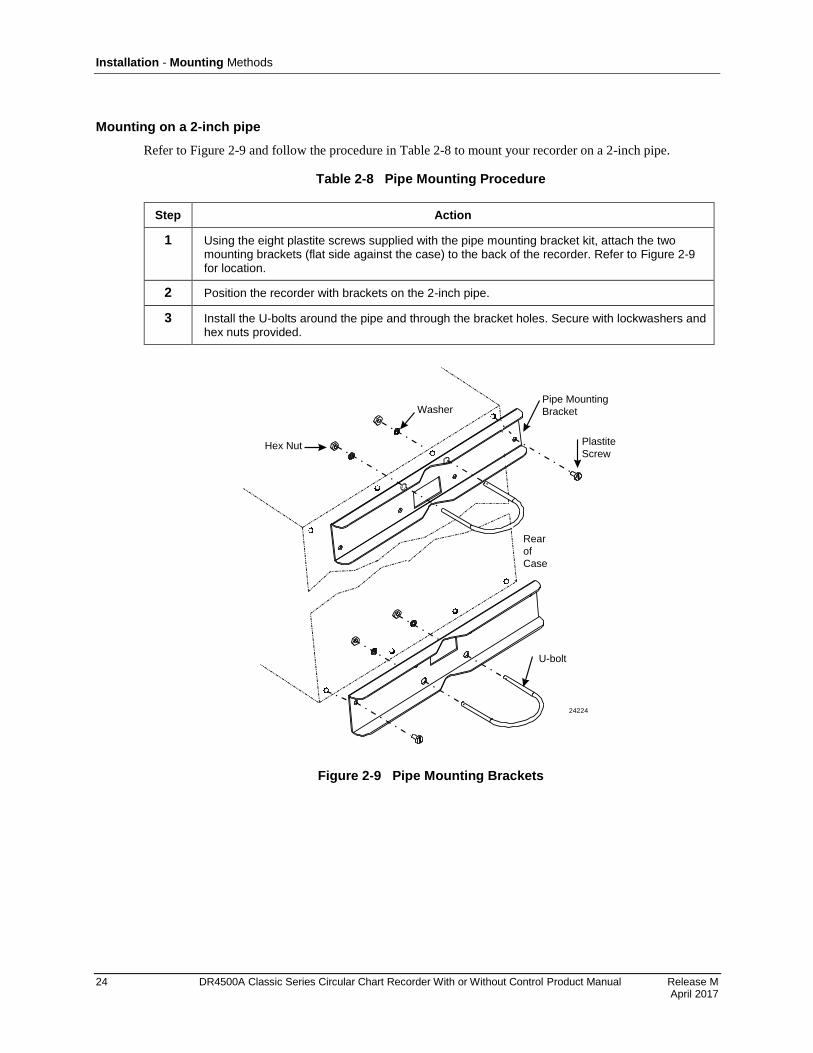
Installation - Mounting Methods
24 DR4500A Classic Series Circular Chart Recorder With or Without Control Product Manual Release M April 2017
Mounting on a 2-inch pipe
Refer to Figure 2-9 and follow the procedure in Table 2-8 to mount your recorder on a 2-inch pipe.
Table 2-8 Pipe Mounting Procedure
Step Action
1 Using the eight plastite screws supplied with the pipe mounting bracket kit, attach the two mounting brackets (flat side against the case) to the back of the recorder. Refer to Figure 2-9 for location.
2 Position the recorder with brackets on the 2-inch pipe.
3 Install the U-bolts around the pipe and through the bracket holes. Secure with lockwashers and hex nuts provided.
Rear
of
Case
24224
Hex Nut
WasherPipe Mounting
Bracket
U-bolt
Plastite
Screw
Figure 2-9 Pipe Mounting Brackets
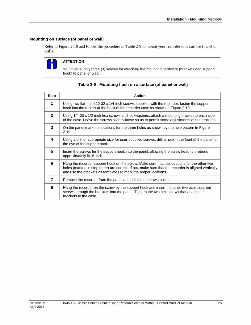
Installation - Mounting Methods
Release M DR4500A Classic Series Circular Chart Recorder With or Without Control Product Manual 25 April 2017
Mounting on surface (of panel or wall)
Refer to Figure 2-10 and follow the procedure in Table 2-9 to mount your recorder on a surface (panel or
wall).
ATTENTION
You must supply three (3) screws for attaching the mounting hardware (brackets and support hook) to panel or wall.
Table 2-9 Mounting flush on a surface (of panel or wall)
Step Action
1 Using two flat-head 10-32 x 1/4-inch screws supplied with the recorder, fasten the support hook into the recess at the back of the recorder case as shown in Figure 2-10.
2 Using 1/4-20 x 1/2-inch hex screws and lockwashers, attach a mounting bracket to each side of the case. Leave the screws slightly loose so as to permit some adjustments of the brackets.
3 On the panel mark the locations for the three holes as shown by the hole pattern in Figure 2-10.
4 Using a drill of appropriate size for user-supplied screws, drill a hole in the front of the panel for the eye of the support hook.
5 Insert the screws for the support hook into the panel, allowing the screw head to protrude approximately 5/16-inch.
6 Hang the recorder support hook on the screw. Make sure that the locations for the other two holes (marked in step three) are correct. If not, make sure that the recorder is aligned vertically and use the brackets as templates to mark the proper locations.
7 Remove the recorder from the panel and drill the other two holes.
8 Hang the recorder on the screw by the support hook and insert the other two user-supplied screws through the brackets into the panel. Tighten the two hex screws that attach the brackets to the case.

Installation - Mounting Methods
26 DR4500A Classic Series Circular Chart Recorder With or Without Control Product Manual Release M April 2017
181.36
7.14
163.32
6.430
18.03
0.710
196.22
7.725
369.6
14.550
Hole Pattern
Reference:millimeters
inches
21409
NOTE:
These screws must be supplied by
user; all other mounting hardware
is supplied with recorder. Support
hook
Figure 2-10 Mounting flush on a surface (of panel or wall)

Installation - Wiring Prerequisites
Release M DR4500A Classic Series Circular Chart Recorder With or Without Control Product Manual 27 April 2017
2.5 Wiring Prerequisites
Taking electrical noise precautions
Electrical noise is composed of unabated electrical signals which produce undesirable effects in
measurements and control circuits.
Digital equipment is especially sensitive to the effects of electrical noise. Your recorder has built-in circuits
to reduce the effect of electrical noise from various sources. If there is a need to further reduce these
effects:
Separate External Wiring - separate connecting wires into bundles (see Table 2-10) and route the
individual bundles through separate conduits or metal trays.
Use Suppression Devices - for additional noise protection, you may want to add suppression devices at
the external source; appropriate suppression devices are commercially available.
REFERENCE
For additional noise information, refer to document number 51-52-05-01.
Electrical considerations
The recorder is considered “rack and panel mounted equipment” per EN 61010-1, Safety
Requirements for Electrical Equipment for Measurement, Control, and Laboratory Use, Part
1: General Requirements.
Recorder grounding
PROTECTIVE BONDING (grounding) of this recorder shall be in accordance with National
and local electrical codes.
Functional Earth
To minimize electrical noise and transients that may adversely affect the system,
supplementary bonding of the recorder enclosure to a functional earth ground, using a 3/4”
braided copper conductor, is required.
A terminal on the rear of the recorder is provided for this connection.
CE conformity special conditions (Europe)
Braid shielded cable is required for all Input I/O and Output Relay cables. All recorder cable shield wires,
except the RS485 Modbus communications cable shield, must be connected to a low impedance earth
ground at the recorder. This can be done by bussing the shields to an earth ground point, or by connecting
the shields to the conduit entry fittings if they are in electrical contact with the enclosure conductive
coating. In either case, the shields shall not extend into the recorder enclosure. The cable shields shall also
be connected to a low impedance earth ground at the farthest end of the cable, through a 0.0047 μF
capacitor. See each of the individual wiring diagrams.
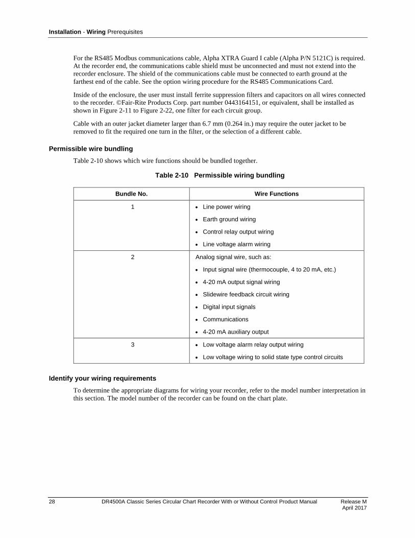
Installation - Wiring Prerequisites
28 DR4500A Classic Series Circular Chart Recorder With or Without Control Product Manual Release M April 2017
For the RS485 Modbus communications cable, Alpha XTRA Guard I cable (Alpha P/N 5121C) is required.
At the recorder end, the communications cable shield must be unconnected and must not extend into the
recorder enclosure. The shield of the communications cable must be connected to earth ground at the
farthest end of the cable. See the option wiring procedure for the RS485 Communications Card.
Inside of the enclosure, the user must install ferrite suppression filters and capacitors on all wires connected
to the recorder. ©Fair-Rite Products Corp. part number 0443164151, or equivalent, shall be installed as
shown in Figure 2-11 to Figure 2-22, one filter for each circuit group.
Cable with an outer jacket diameter larger than 6.7 mm (0.264 in.) may require the outer jacket to be
removed to fit the required one turn in the filter, or the selection of a different cable.
Permissible wire bundling
Table 2-10 shows which wire functions should be bundled together.
Table 2-10 Permissible wiring bundling
Bundle No. Wire Functions
1 Line power wiring
Earth ground wiring
Control relay output wiring
Line voltage alarm wiring
2 Analog signal wire, such as:
Input signal wire (thermocouple, 4 to 20 mA, etc.)
4-20 mA output signal wiring
Slidewire feedback circuit wiring
Digital input signals
Communications
4-20 mA auxiliary output
3 Low voltage alarm relay output wiring
Low voltage wiring to solid state type control circuits
Identify your wiring requirements
To determine the appropriate diagrams for wiring your recorder, refer to the model number interpretation in
this section. The model number of the recorder can be found on the chart plate.
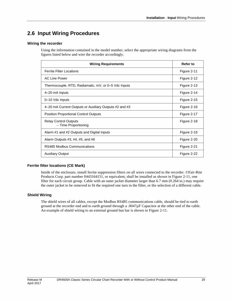
Installation - Input Wiring Procedures
Release M DR4500A Classic Series Circular Chart Recorder With or Without Control Product Manual 29 April 2017
2.6 Input Wiring Procedures
Wiring the recorder
Using the information contained in the model number, select the appropriate wiring diagrams from the
figures listed below and wire the recorder accordingly.
Wiring Requirements Refer to
Ferrite Filter Locations Figure 2-11
AC Line Power Figure 2-12
Thermocouple, RTD, Radiamatic, mV, or 0–5 Vdc Inputs Figure 2-13
4–20 mA Inputs Figure 2-14
0–10 Vdc Inputs Figure 2-15
4–20 mA Current Outputs or Auxiliary Outputs #2 and #3 Figure 2-16
Position Proportional Control Outputs Figure 2-17
Relay Control Outputs – Time Proportioning
Figure 2-18
Alarm #1 and #2 Outputs and Digital Inputs Figure 2-19
Alarm Outputs #3, #4, #5, and #6 Figure 2-20
RS485 Modbus Communications Figure 2-21
Auxiliary Output Figure 2-22
Ferrite filter locations (CE Mark)
Inside of the enclosure, install ferrite suppression filters on all wires connected to the recorder. ©Fair-Rite
Products Corp. part number 0443164151, or equivalent, shall be installed as shown in Figure 2-11, one
filter for each circuit group. Cable with an outer jacket diameter larger than 6.7 mm (0.264 in.) may require
the outer jacket to be removed to fit the required one turn in the filter, or the selection of a different cable.
Shield Wiring
The shield wires of all cables, except the Modbus RS485 communications cable, should be tied to earth
ground at the recorder end and to earth ground through a .0047µF Capacitor at the other end of the cable.
An example of shield wiring to an external ground bus bar is shown in Figure 2-11.
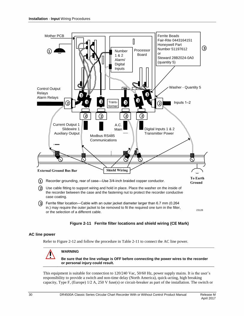
Installation - Input Wiring Procedures
30 DR4500A Classic Series Circular Chart Recorder With or Without Control Product Manual Release M April 2017
Trans-
former
Mother PCB
Number
1 & 2
Alarm/
Digital
Inputs
Ferrite Beads
Fair-Rite 0443164151
Honeywell Part
Number 51197612
or
Steward 28B2024-0A0
(quantity 5)
Control Output
Relays
Alarm Relays
Current Output 1
Slidewire 1
Auxiliary Output
A.C.
Main Digital Inputs 1 & 2
Transmitter Power
Inputs 1–2
23128
Washer - Quantity 5
Processor
Board
Modbus RS485
Communications
1
2
3
333
3
3
2 2 2 2
23
External Ground Bus Bar
To Earth
Ground
Shield Wiring
1 Recorder grounding, rear of case—Use 3/4-inch braided copper conductor.
2 Use cable fitting to support wiring and hold in place. Place the washer on the inside of
the recorder between the case and the fastening nut to protect the recorder conductive
case coating.
3 Ferrite filter location—Cable with an outer jacket diameter larger than 6.7 mm (0.264
in.) may require the outer jacket to be removed to fit the required one turn in the filter,
or the selection of a different cable.
Figure 2-11 Ferrite filter locations and shield wiring (CE Mark)
AC line power
Refer to Figure 2-12 and follow the procedure in Table 2-11 to connect the AC line power.
WARNING
Be sure that the line voltage is OFF before connecting the power wires to the recorder or personal injury could result.
This equipment is suitable for connection to 120/240 Vac, 50/60 Hz, power supply mains. It is the user’s
responsibility to provide a switch and non-time delay (North America), quick-acting, high breaking
capacity, Type F, (Europe) 1/2 A, 250 V fuse(s) or circuit-breaker as part of the installation. The switch or
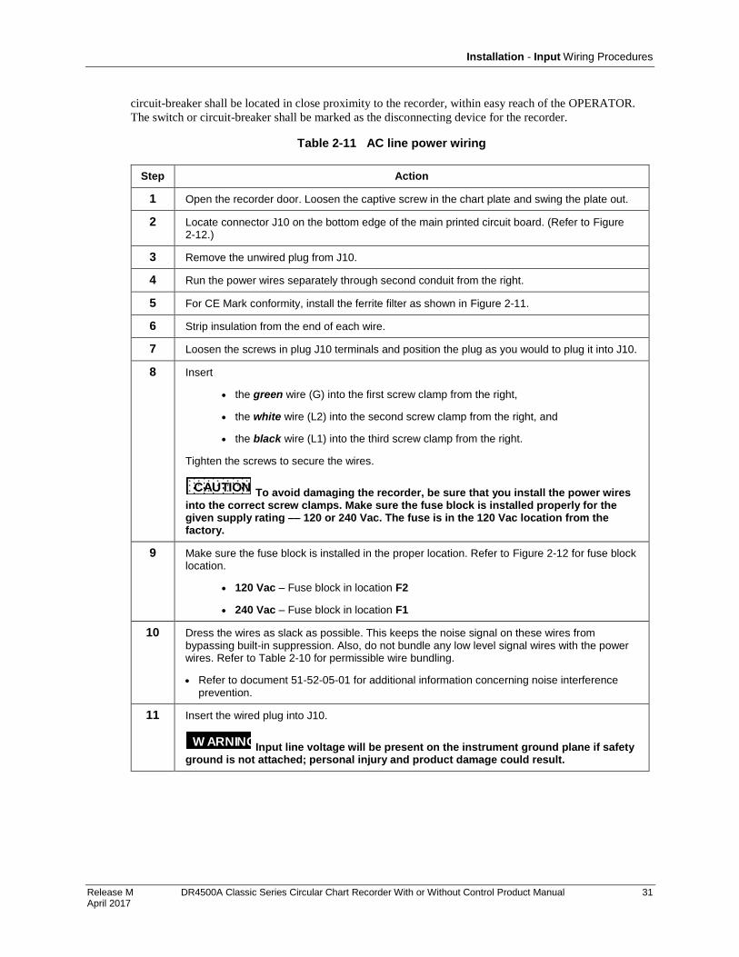
Installation - Input Wiring Procedures
Release M DR4500A Classic Series Circular Chart Recorder With or Without Control Product Manual 31 April 2017
circuit-breaker shall be located in close proximity to the recorder, within easy reach of the OPERATOR.
The switch or circuit-breaker shall be marked as the disconnecting device for the recorder.
Table 2-11 AC line power wiring
Step Action
1 Open the recorder door. Loosen the captive screw in the chart plate and swing the plate out.
2 Locate connector J10 on the bottom edge of the main printed circuit board. (Refer to Figure 2-12.)
3 Remove the unwired plug from J10.
4 Run the power wires separately through second conduit from the right.
5 For CE Mark conformity, install the ferrite filter as shown in Figure 2-11.
6 Strip insulation from the end of each wire.
7 Loosen the screws in plug J10 terminals and position the plug as you would to plug it into J10.
8 Insert
the green wire (G) into the first screw clamp from the right,
the white wire (L2) into the second screw clamp from the right, and
the black wire (L1) into the third screw clamp from the right.
Tighten the screws to secure the wires.
CAUTION To avoid damaging the recorder, be sure that you install the power wires into the correct screw clamps. Make sure the fuse block is installed properly for the given supply rating –– 120 or 240 Vac. The fuse is in the 120 Vac location from the factory.
9 Make sure the fuse block is installed in the proper location. Refer to Figure 2-12 for fuse block location.
120 Vac – Fuse block in location F2
240 Vac – Fuse block in location F1
10 Dress the wires as slack as possible. This keeps the noise signal on these wires from bypassing built-in suppression. Also, do not bundle any low level signal wires with the power wires. Refer to Table 2-10 for permissible wire bundling.
Refer to document 51-52-05-01 for additional information concerning noise interference prevention.
11 Insert the wired plug into J10.
W ARNING Input line voltage will be present on the instrument ground plane if safety ground is not attached; personal injury and product damage could result.
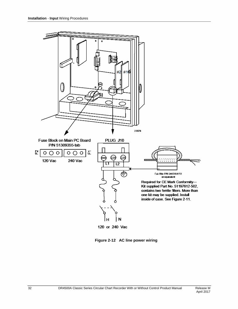
Installation - Input Wiring Procedures
32 DR4500A Classic Series Circular Chart Recorder With or Without Control Product Manual Release M April 2017
Figure 2-12 AC line power wiring

Installation - Input Wiring Procedures
Release M DR4500A Classic Series Circular Chart Recorder With or Without Control Product Manual 33 April 2017
Thermocouple, RTD, Radiamatic, mV, or 0-5 Vdc inputs
You can wire input 1 or 2 for thermocouple, RTD, Radiamatic, mV, or 0-5 Vdc actuations.
The polarity for inputs #1 and #2 is identical.
The prerequisites are:
Model Number - Table 1 = 1X00, X100
ATTENTION
For thermocouple or RTD inputs, calibrate the recorder to achieve the stated accuracy. Refer to Section 7 – Input Calibration
Refer to Figure 2-13 and follow the procedure in Table 2-12 to wire Thermocouple, RTD, Radiamatic, mV,
or 0–5 Vdc inputs.
Table 2-12 Thermocouple, RTD, Radiamatic, mV, or 0–5 Vdc input wiring
Step Action
1 Open the recorder door. Loosen the captive screw in the chart plate and swing the plate out.
2 Locate connector J2 on the printed circuit board for input 1 (refer to Figure 2-13).
3 Remove the unwired plug from J2.
4 Run the input wires through the desired knockout - DO NOT bundle them with the power wires.
5 For CE Mark conformity:
Install the ferrite filter as shown in Figure 2-11.
Install a .01µF capacitor across the J2 terminals and a .0047 µF capacitor at the sensor end of the input wiring as shown in Figure 2-13.
6 Locate jumper position MA/W1 and make sure the jumper is in the W1 position. (See Figure 2-13 for the jumper positions.)
7 Locate jumper position W3 and make sure the jumper is in the proper position for your input type. (See Figure 2-13 for the jumper positions.)
8 Strip insulation from the end of each wire.
9 Loosen the screws in plug J2 terminals and position the plug as you would to plug it into J2.
10 Insert the wires into the appropriate screw clamps for the applicable input type. See Figure 2-13 for specific input actuation plug wiring. Tighten the screws to secure the wires.
11 Insert the wired plug into J2.
12 Repeat steps 2 through 11 for input 2 printed circuit board as applicable.
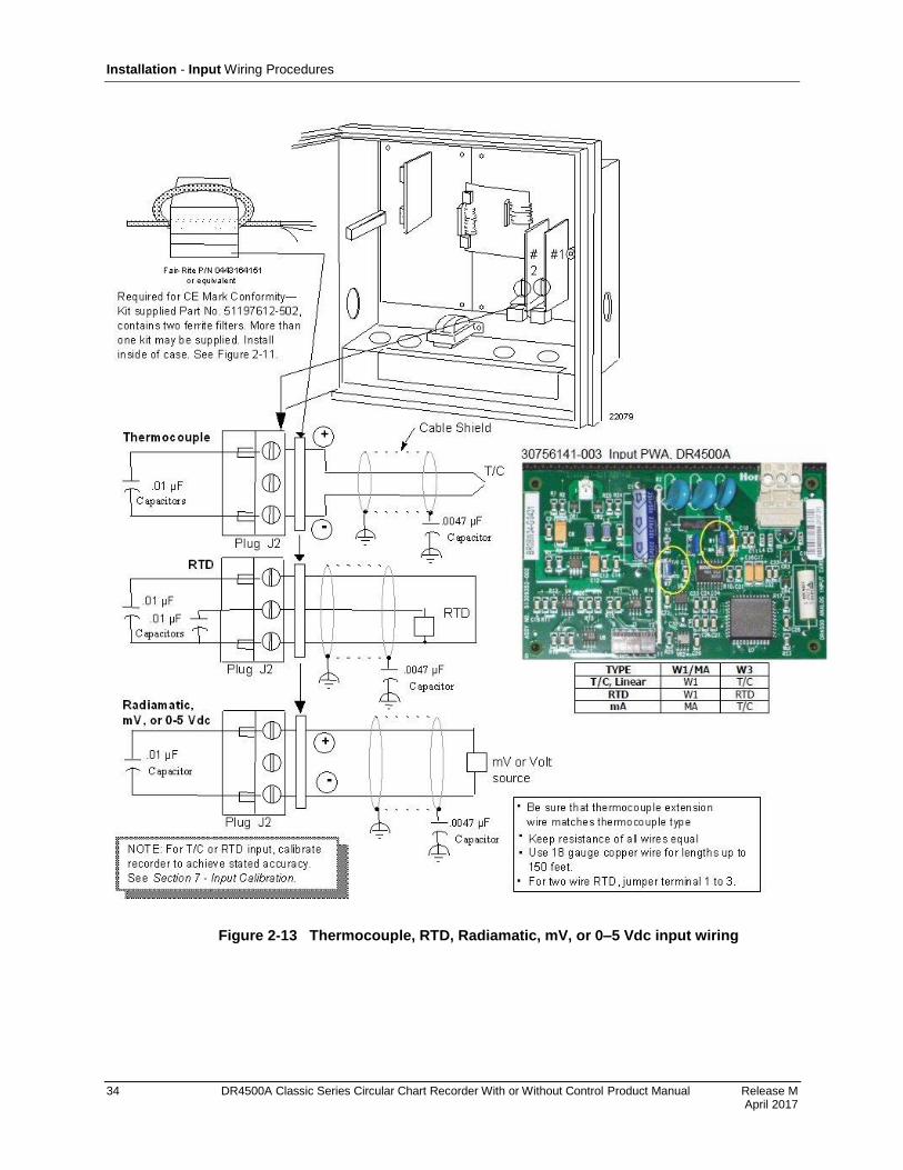
Installation - Input Wiring Procedures
34 DR4500A Classic Series Circular Chart Recorder With or Without Control Product Manual Release M April 2017
Figure 2-13 Thermocouple, RTD, Radiamatic, mV, or 0–5 Vdc input wiring
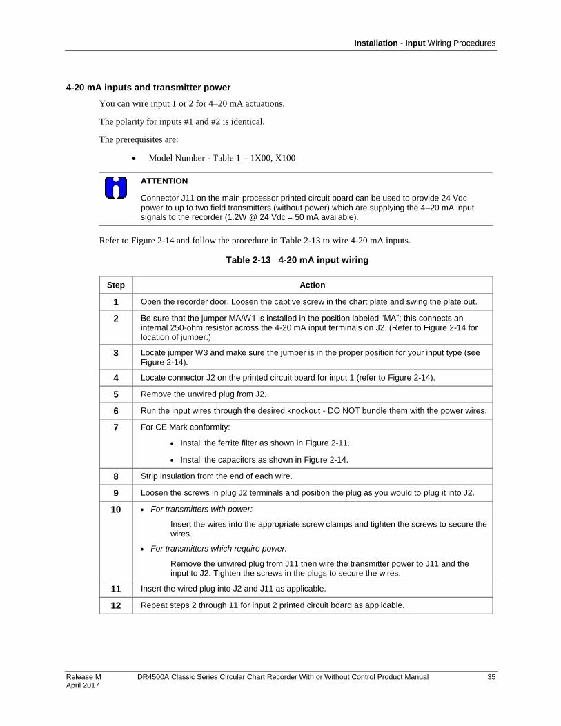
Installation - Input Wiring Procedures
Release M DR4500A Classic Series Circular Chart Recorder With or Without Control Product Manual 35 April 2017
4-20 mA inputs and transmitter power
You can wire input 1 or 2 for 4–20 mA actuations.
The polarity for inputs #1 and #2 is identical.
The prerequisites are:
Model Number - Table 1 = 1X00, X100
ATTENTION
Connector J11 on the main processor printed circuit board can be used to provide 24 Vdc power to up to two field transmitters (without power) which are supplying the 4–20 mA input signals to the recorder (1.2W @ 24 Vdc = 50 mA available).
Refer to Figure 2-14 and follow the procedure in Table 2-13 to wire 4-20 mA inputs.
Table 2-13 4-20 mA input wiring
Step Action
1 Open the recorder door. Loosen the captive screw in the chart plate and swing the plate out.
2 Be sure that the jumper MA/W1 is installed in the position labeled “MA”; this connects an internal 250-ohm resistor across the 4-20 mA input terminals on J2. (Refer to Figure 2-14 for location of jumper.)
3 Locate jumper W3 and make sure the jumper is in the proper position for your input type (see Figure 2-14).
4 Locate connector J2 on the printed circuit board for input 1 (refer to Figure 2-14).
5 Remove the unwired plug from J2.
6 Run the input wires through the desired knockout - DO NOT bundle them with the power wires.
7 For CE Mark conformity:
Install the ferrite filter as shown in Figure 2-11.
Install the capacitors as shown in Figure 2-14.
8 Strip insulation from the end of each wire.
9 Loosen the screws in plug J2 terminals and position the plug as you would to plug it into J2.
10 For transmitters with power:
Insert the wires into the appropriate screw clamps and tighten the screws to secure the wires.
For transmitters which require power:
Remove the unwired plug from J11 then wire the transmitter power to J11 and the input to J2. Tighten the screws in the plugs to secure the wires.
11 Insert the wired plug into J2 and J11 as applicable.
12 Repeat steps 2 through 11 for input 2 printed circuit board as applicable.
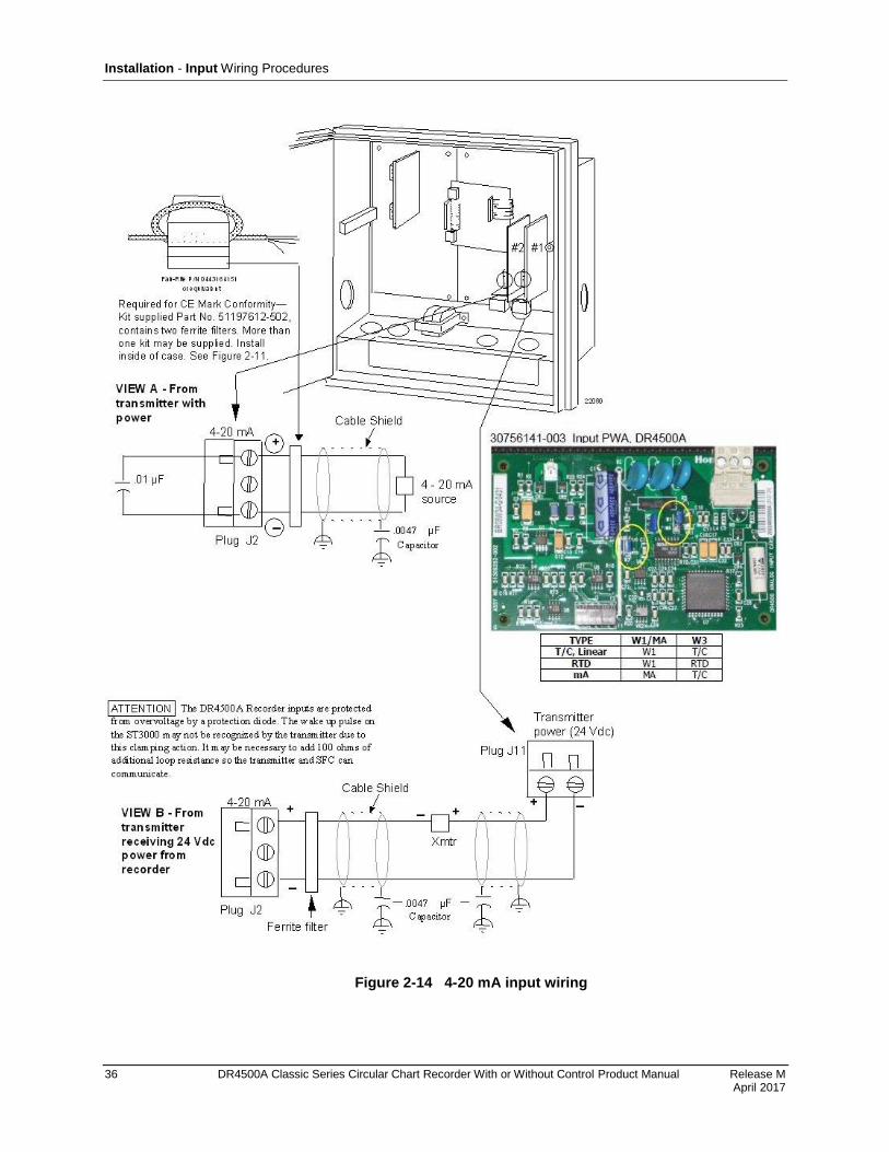
Installation - Input Wiring Procedures
36 DR4500A Classic Series Circular Chart Recorder With or Without Control Product Manual Release M April 2017
Figure 2-14 4-20 mA input wiring
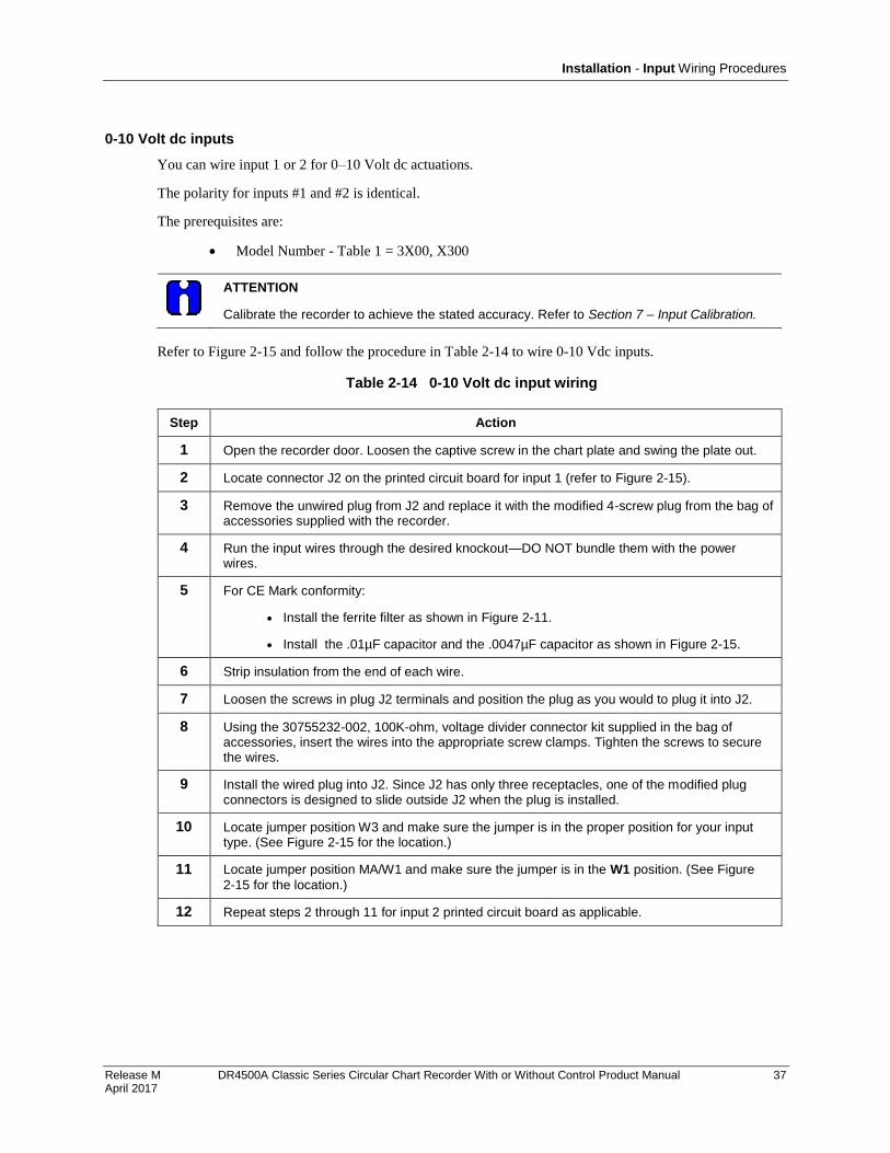
Installation - Input Wiring Procedures
Release M DR4500A Classic Series Circular Chart Recorder With or Without Control Product Manual 37 April 2017
0-10 Volt dc inputs
You can wire input 1 or 2 for 0–10 Volt dc actuations.
The polarity for inputs #1 and #2 is identical.
The prerequisites are:
Model Number - Table 1 = 3X00, X300
ATTENTION
Calibrate the recorder to achieve the stated accuracy. Refer to Section 7 – Input Calibration.
Refer to Figure 2-15 and follow the procedure in Table 2-14 to wire 0-10 Vdc inputs.
Table 2-14 0-10 Volt dc input wiring
Step Action
1 Open the recorder door. Loosen the captive screw in the chart plate and swing the plate out.
2 Locate connector J2 on the printed circuit board for input 1 (refer to Figure 2-15).
3 Remove the unwired plug from J2 and replace it with the modified 4-screw plug from the bag of accessories supplied with the recorder.
4 Run the input wires through the desired knockout—DO NOT bundle them with the power wires.
5 For CE Mark conformity:
Install the ferrite filter as shown in Figure 2-11.
Install the .01µF capacitor and the .0047µF capacitor as shown in Figure 2-15.
6 Strip insulation from the end of each wire.
7 Loosen the screws in plug J2 terminals and position the plug as you would to plug it into J2.
8 Using the 30755232-002, 100K-ohm, voltage divider connector kit supplied in the bag of accessories, insert the wires into the appropriate screw clamps. Tighten the screws to secure the wires.
9 Install the wired plug into J2. Since J2 has only three receptacles, one of the modified plug connectors is designed to slide outside J2 when the plug is installed.
10 Locate jumper position W3 and make sure the jumper is in the proper position for your input type. (See Figure 2-15 for the location.)
11 Locate jumper position MA/W1 and make sure the jumper is in the W1 position. (See Figure
2-15 for the location.)
12 Repeat steps 2 through 11 for input 2 printed circuit board as applicable.
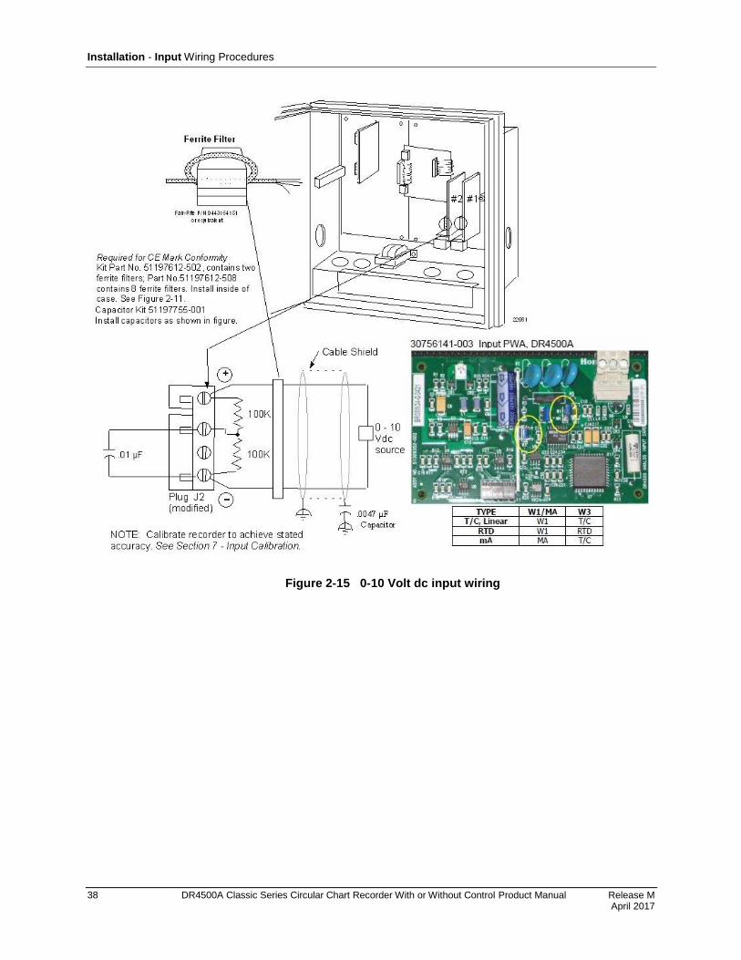
Installation - Input Wiring Procedures
38 DR4500A Classic Series Circular Chart Recorder With or Without Control Product Manual Release M April 2017
Figure 2-15 0-10 Volt dc input wiring
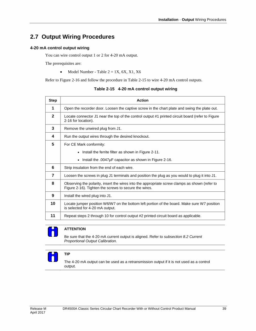
Installation - Output Wiring Procedures
Release M DR4500A Classic Series Circular Chart Recorder With or Without Control Product Manual 39 April 2017
2.7 Output Wiring Procedures
4-20 mA control output wiring
You can wire control output 1 or 2 for 4-20 mA output.
The prerequisites are:
Model Number - Table 2 = 1X, 6X, X1, X6
Refer to Figure 2-16 and follow the procedure in Table 2-15 to wire 4-20 mA control outputs.
Table 2-15 4-20 mA control output wiring
Step Action
1 Open the recorder door. Loosen the captive screw in the chart plate and swing the plate out.
2 Locate connector J1 near the top of the control output #1 printed circuit board (refer to Figure 2-16 for location).
3 Remove the unwired plug from J1.
4 Run the output wires through the desired knockout.
5 For CE Mark conformity:
Install the ferrite filter as shown in Figure 2-11.
Install the .0047µF capacitor as shown in Figure 2-16.
6 Strip insulation from the end of each wire.
7 Loosen the screws in plug J1 terminals and position the plug as you would to plug it into J1.
8 Observing the polarity, insert the wires into the appropriate screw clamps as shown (refer to Figure 2-16). Tighten the screws to secure the wires.
9 Install the wired plug into J1.
10 Locate jumper position W6/W7 on the bottom left portion of the board. Make sure W7 position is selected for 4-20 mA output.
11 Repeat steps 2 through 10 for control output #2 printed circuit board as applicable.
ATTENTION
Be sure that the 4-20 mA current output is aligned. Refer to subsection 8.2 Current Proportional Output Calibration.
TIP
The 4-20 mA output can be used as a retransmission output if it is not used as a control output.
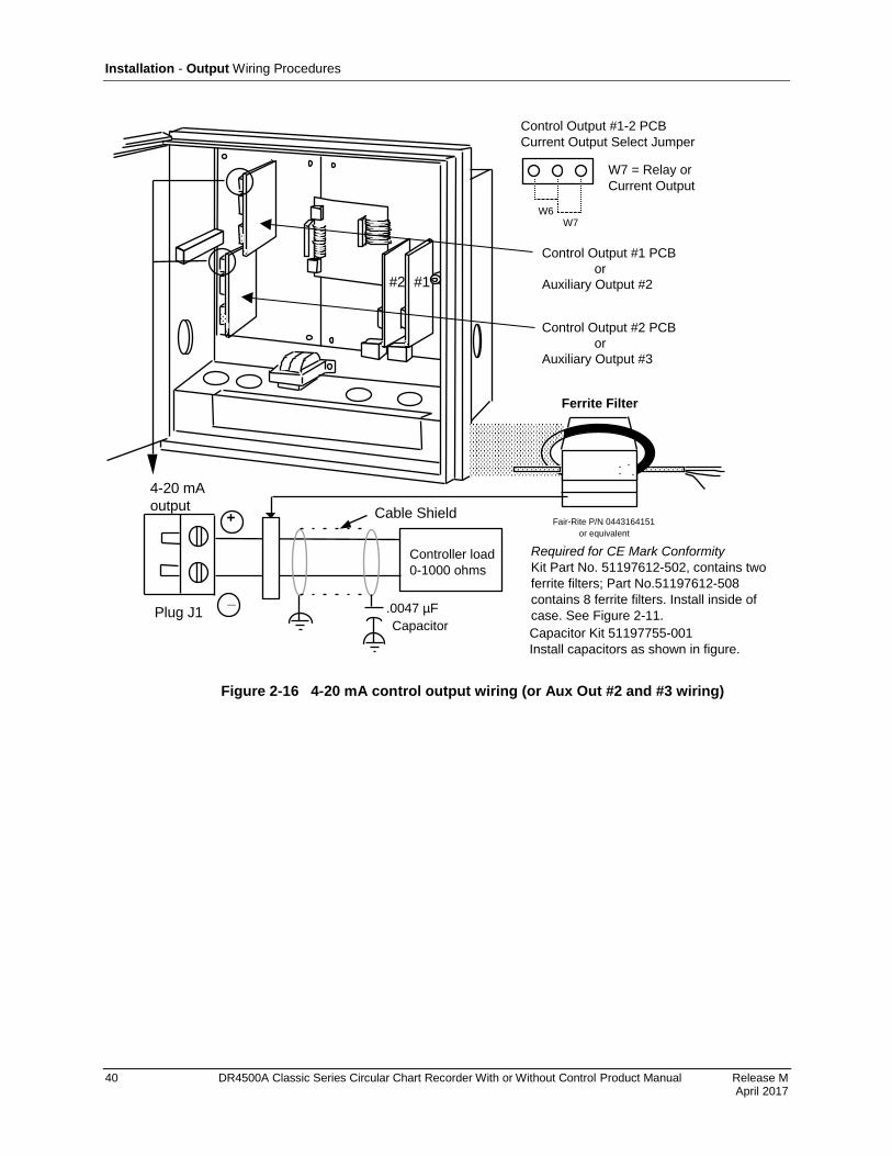
Installation - Output Wiring Procedures
40 DR4500A Classic Series Circular Chart Recorder With or Without Control Product Manual Release M April 2017
#2 #1
22082
W6W7
Control Output #1-2 PCB
Current Output Select Jumper
W7 = Relay or
Current Output
+
_
Controller load
0-1000 ohms
4-20 mA
output
Plug J1
Fair-Rite P/N 0443164151
or equivalent
Ferrite Filter
Capacitor Kit 51197755-001
Install capacitors as shown in figure.
Required for CE Mark Conformity
Kit Part No. 51197612-502, contains two
ferrite filters; Part No.51197612-508
contains 8 ferrite filters. Install inside of
case. See Figure 2-11.
Cable Shield
.0047 µF
Capacitor
Control Output #1 PCB
or
Auxiliary Output #2
Control Output #2 PCB
or
Auxiliary Output #3
Figure 2-16 4-20 mA control output wiring (or Aux Out #2 and #3 wiring)
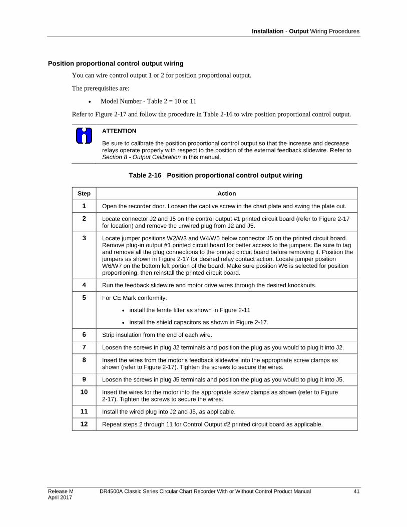
Installation - Output Wiring Procedures
Release M DR4500A Classic Series Circular Chart Recorder With or Without Control Product Manual 41 April 2017
Position proportional control output wiring
You can wire control output 1 or 2 for position proportional output.
The prerequisites are:
Model Number - Table 2 = 10 or 11
Refer to Figure 2-17 and follow the procedure in Table 2-16 to wire position proportional control output.
ATTENTION
Be sure to calibrate the position proportional control output so that the increase and decrease relays operate properly with respect to the position of the external feedback slidewire. Refer to Section 8 - Output Calibration in this manual.
Table 2-16 Position proportional control output wiring
Step Action
1 Open the recorder door. Loosen the captive screw in the chart plate and swing the plate out.
2 Locate connector J2 and J5 on the control output #1 printed circuit board (refer to Figure 2-17 for location) and remove the unwired plug from J2 and J5.
3 Locate jumper positions W2/W3 and W4/W5 below connector J5 on the printed circuit board. Remove plug-in output #1 printed circuit board for better access to the jumpers. Be sure to tag and remove all the plug connections to the printed circuit board before removing it. Position the jumpers as shown in Figure 2-17 for desired relay contact action. Locate jumper position W6/W7 on the bottom left portion of the board. Make sure position W6 is selected for position proportioning, then reinstall the printed circuit board.
4 Run the feedback slidewire and motor drive wires through the desired knockouts.
5 For CE Mark conformity:
install the ferrite filter as shown in Figure 2-11
install the shield capacitors as shown in Figure 2-17.
6 Strip insulation from the end of each wire.
7 Loosen the screws in plug J2 terminals and position the plug as you would to plug it into J2.
8 Insert the wires from the motor’s feedback slidewire into the appropriate screw clamps as shown (refer to Figure 2-17). Tighten the screws to secure the wires.
9 Loosen the screws in plug J5 terminals and position the plug as you would to plug it into J5.
10 Insert the wires for the motor into the appropriate screw clamps as shown (refer to Figure 2-17). Tighten the screws to secure the wires.
11 Install the wired plug into J2 and J5, as applicable.
12 Repeat steps 2 through 11 for Control Output #2 printed circuit board as applicable.
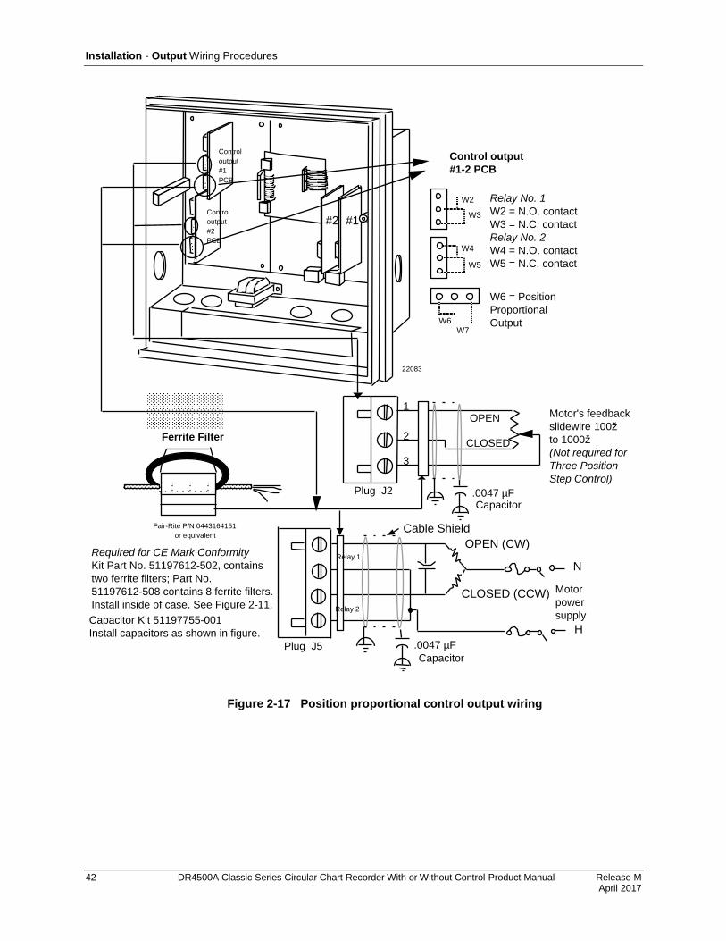
Installation - Output Wiring Procedures
42 DR4500A Classic Series Circular Chart Recorder With or Without Control Product Manual Release M April 2017
#2 #1
22083
Control
output
#1
PCB
Control
output
#2
PCB
Control output
#1-2 PCB
Relay No. 1
W2 = N.O. contact
W3 = N.C. contact
Relay No. 2
W4 = N.O. contact
W5 = N.C. contactW5
W4
W3
W2
W6W7
W6 = Position
Proportional
Output
Fair-Rite P/N 0443164151
or equivalent
Ferrite Filter
1
2
3
Plug J2
OPEN
CLOSED
Motor's feedback
slidewire 100ž
to 1000ž
(Not required for
Three Position
Step Control)
Plug J5
N
H
Motor
power
supply
CLOSED (CCW)
OPEN (CW)
Capacitor Kit 51197755-001
Install capacitors as shown in figure.
Required for CE Mark Conformity
Kit Part No. 51197612-502, contains
two ferrite filters; Part No.
51197612-508 contains 8 ferrite filters.
Install inside of case. See Figure 2-11.
Cable Shield
.0047 µFCapacitor
Relay 2
Relay 1
.0047 µF
Capacitor
Figure 2-17 Position proportional control output wiring
Installation - Output Wiring Procedures
Release M DR4500A Classic Series Circular Chart Recorder With or Without Control Product Manual 43 April 2017
Relay control output wiring
You can wire control output 1 or 2 for relay output including Time proportional applications.
The prerequisites are:
Model Number - Table 2 = 1X or X1
Refer to Figure 2-18 and follow the procedure in Table 2-17 to wire relay control outputs.
ATTENTION
Relay #2 is used for time proportional control.
Table 2-17 Relay control output wiring
Step Action
1 Open the recorder door. Loosen the captive screw in the chart plate and swing the plate out.
2 Locate connector J5 on the control output #1 printed circuit board (refer to Figure 2-18 for location).
3 Remove the unwired plug from J5.
4 Locate jumper positions W2/W3 and W4/W5 below connector J5 on the printed circuit board. Remove plug-in output #1 printed circuit board for better access to the jumpers. Be sure to tag and remove all the plug connections to the printed circuit board before removing it. Position the jumpers as shown in Figure 2-18 for desired relay contact action. Locate jumper position W6/W7 on the bottom left portion of the board. Make sure W7 position is selected for relay control output, then reinstall the printed circuit board.
5 Run the relay load wires through the desired knockouts.
6 For CE Mark conformity:
Install the ferrite filter as shown in Figure 2-11.
Install the shield capacitor as shown in Figure 2-18.
7 Strip insulation from the end of each wire.
8 Loosen the screws in plug J5 terminals and position the plug as you would to plug it into J5.
9 Insert the relay wires and relay power into the appropriate screw clamps for single or duplex action as shown (refer to Figure 2-18); tighten the screws to secure the wires.
10 Install the wired plug into J5.
11 Repeat steps 2 through 10 for control output #2 printed circuit board as applicable.

Installation - Output Wiring Procedures
44 DR4500A Classic Series Circular Chart Recorder With or Without Control Product Manual Release M April 2017
#2 #1
22084
Position when shipped
N.O. with power applied
and OUT indicator light off.
Control
output
#1
PCB
Control
output
#2
PCB
Relay No. 1
W2 = N.O. contact
W3 = N.C. contact
Relay No. 2
W4 = N.O. contact
W5 = N.C. contact
Control output
#1-2 PCB
W5
W4
W3
W2
W6
W7
.
controlled devicethan 5 amps
Notes:
1.
2.
3.
J5 terminals 2 and 4 are the non-switched connections to an SPST relay.
Selectable for normally open or normally closed as required.
This relay supplies a dry contact closure. User must supply appropriate
power connections for his external device.
This relay has a resistive load rating of 5A @ 120 Vac
Load calculation example:
Supply voltage
(for example: 115 Vac)
Resistance of customer =
must equal a
number less
N
H
Plug J5 (see Notes)
Relay 2
load
H
N
Relay 1
load
External Load
power supply
*Relay 2 is used for time proportional duplex.
Also used for 3 position step. See Figure 2-17.
Heat
Cooling
*
Fair-Rite P/N 0443164151
or equivalent
Ferrite Filter
Cable Shield
.0047
Capacitor
Fµ
Capacitor Kit 51197755-001
Install capacitors as shown in figure.
Required for CE Mark Conformity
Kit Part No. 51197612-502, contains two
ferrite filters; Part No.51197612-508
contains 8 ferrite filters. Install inside of
case. See Figure 2-11.
W7 = Relay or
Current Output
Figure 2-18 Relay control output wiring
Installation - Option Wiring Procedures
Release M DR4500A Classic Series Circular Chart Recorder With or Without Control Product Manual 45 April 2017
2.8 Option Wiring Procedures
Alarm output and digital input wiring
You can wire #1 and #2 Alarm Outputs and Digital Inputs.
The prerequisites are:
Model Number - Table 3 = XX1
Refer to Figure 2-19 and follow the procedure in Table 2-18 to wire alarm outputs or digital inputs.
The alarm output is a dry contact closure.
Table 2-18 Alarm output or digital input wiring
Step Action
1 Open the recorder door. Loosen the captive screw in the chart plate and swing the plate out.
2 Locate connector J3 and J4 on the alarm output/digital input printed circuit board (refer to Figure 2-19 for location).
3 Remove the unwired plug from J3.
4 Run the digital input wires through the desired knockout.
5 For CE Mark conformity, install the ferrite filter as shown in Figure 2-11.
6 Strip insulation from the end of each wire.
7 Loosen the screws in plug J3 terminals and position the plug as you would to plug it into J3.
8 Insert the wires for the digital inputs into the appropriate screw clamps as shown (refer to Figure 2-19). Note that you can wire the contacts in an and /or fashion, so that both contacts or either contact initiates the configured action. Tighten the screws to secure the wires.
9 Install the wired plug into J3.
10 Remove the unwired plug from J4.
11 Run the alarm output wires through the desired knockout.
12 For CE Mark conformity:
install the ferrite filter as shown in Figure 2-11
install the shield capacitors as shown in Figure 2-19.
13 Strip insulation from the end of each wire.
14 Loosen the screws in plug J4 terminals and position the plug as you would to plug it into J4.
15 Insert the wires for the alarm devices into the appropriate screw clamps as shown (refer to Figure 2-19). Tighten the screws to secure the wires.
16 Locate the jumper positions W1/W2 and W3/W4 on the printed circuit board. Reposition the jumpers as shown in Figure 2-19 for the desired relay control action. The recorder is shipped with the W1 and W3 in N.C. positions.
17 Install the wired plug into J4.

Installation - Option Wiring Procedures
46 DR4500A Classic Series Circular Chart Recorder With or Without Control Product Manual Release M April 2017
Figure 2-19 Alarm output or digital input wiring
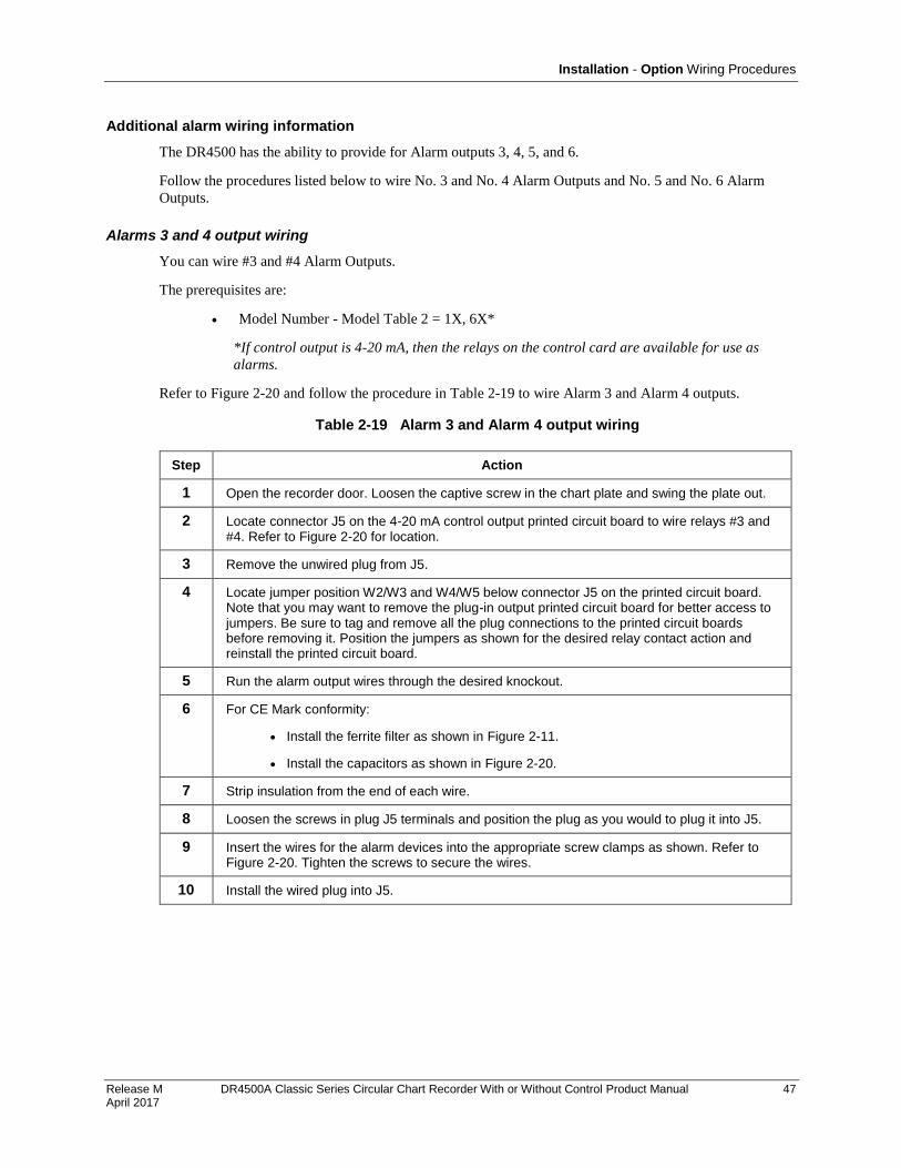
Installation - Option Wiring Procedures
Release M DR4500A Classic Series Circular Chart Recorder With or Without Control Product Manual 47 April 2017
Additional alarm wiring information
The DR4500 has the ability to provide for Alarm outputs 3, 4, 5, and 6.
Follow the procedures listed below to wire No. 3 and No. 4 Alarm Outputs and No. 5 and No. 6 Alarm
Outputs.
Alarms 3 and 4 output wiring
You can wire #3 and #4 Alarm Outputs.
The prerequisites are:
Model Number - Model Table 2 = 1X, 6X*
*If control output is 4-20 mA, then the relays on the control card are available for use as
alarms.
Refer to Figure 2-20 and follow the procedure in Table 2-19 to wire Alarm 3 and Alarm 4 outputs.
Table 2-19 Alarm 3 and Alarm 4 output wiring
Step Action
1 Open the recorder door. Loosen the captive screw in the chart plate and swing the plate out.
2 Locate connector J5 on the 4-20 mA control output printed circuit board to wire relays #3 and #4. Refer to Figure 2-20 for location.
3 Remove the unwired plug from J5.
4 Locate jumper position W2/W3 and W4/W5 below connector J5 on the printed circuit board. Note that you may want to remove the plug-in output printed circuit board for better access to jumpers. Be sure to tag and remove all the plug connections to the printed circuit boards before removing it. Position the jumpers as shown for the desired relay contact action and reinstall the printed circuit board.
5 Run the alarm output wires through the desired knockout.
6 For CE Mark conformity:
Install the ferrite filter as shown in Figure 2-11.
Install the capacitors as shown in Figure 2-20.
7 Strip insulation from the end of each wire.
8 Loosen the screws in plug J5 terminals and position the plug as you would to plug it into J5.
9 Insert the wires for the alarm devices into the appropriate screw clamps as shown. Refer to Figure 2-20. Tighten the screws to secure the wires.
10 Install the wired plug into J5.
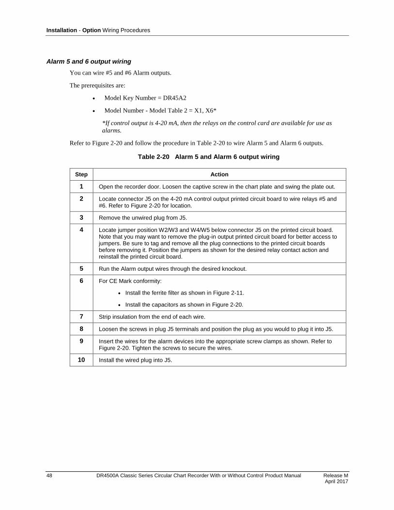
Installation - Option Wiring Procedures
48 DR4500A Classic Series Circular Chart Recorder With or Without Control Product Manual Release M April 2017
Alarm 5 and 6 output wiring
You can wire #5 and #6 Alarm outputs.
The prerequisites are:
Model Key Number = DR45A2
Model Number - Model Table 2 = X1, X6*
*If control output is 4-20 mA, then the relays on the control card are available for use as
alarms.
Refer to Figure 2-20 and follow the procedure in Table 2-20 to wire Alarm 5 and Alarm 6 outputs.
Table 2-20 Alarm 5 and Alarm 6 output wiring
Step Action
1 Open the recorder door. Loosen the captive screw in the chart plate and swing the plate out.
2 Locate connector J5 on the 4-20 mA control output printed circuit board to wire relays #5 and #6. Refer to Figure 2-20 for location.
3 Remove the unwired plug from J5.
4 Locate jumper position W2/W3 and W4/W5 below connector J5 on the printed circuit board. Note that you may want to remove the plug-in output printed circuit board for better access to jumpers. Be sure to tag and remove all the plug connections to the printed circuit boards before removing it. Position the jumpers as shown for the desired relay contact action and reinstall the printed circuit board.
5 Run the Alarm output wires through the desired knockout.
6 For CE Mark conformity:
Install the ferrite filter as shown in Figure 2-11.
Install the capacitors as shown in Figure 2-20.
7 Strip insulation from the end of each wire.
8 Loosen the screws in plug J5 terminals and position the plug as you would to plug it into J5.
9 Insert the wires for the alarm devices into the appropriate screw clamps as shown. Refer to Figure 2-20. Tighten the screws to secure the wires.
10 Install the wired plug into J5.
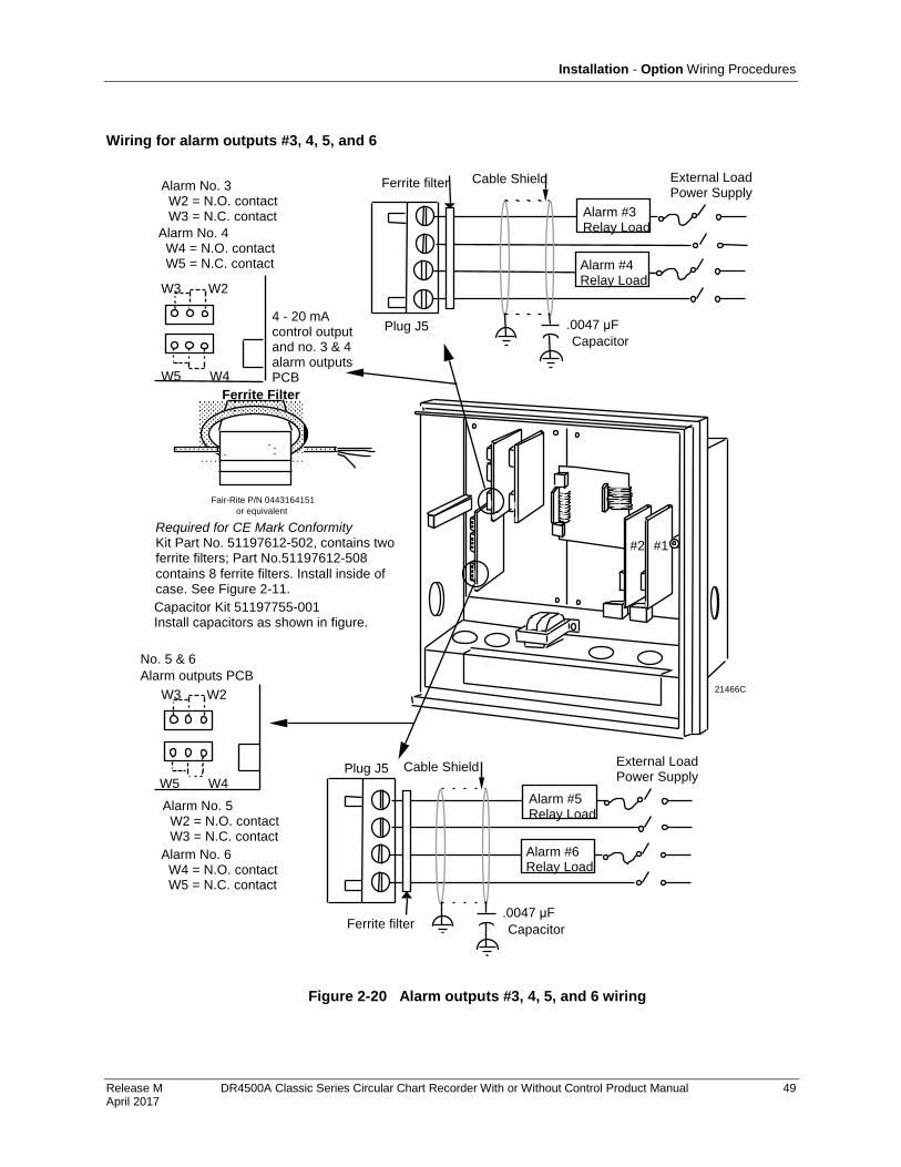
Installation - Option Wiring Procedures
Release M DR4500A Classic Series Circular Chart Recorder With or Without Control Product Manual 49 April 2017
Wiring for alarm outputs #3, 4, 5, and 6
Plug J5
4 - 20 mA control output and no. 3 & 4 alarm outputs PCB
Alarm No. 4 W4 = N.O. contact W5 = N.C. contact
W3 W2
W5 W4
Alarm No. 3 W2 = N.O. contact W3 = N.C. contact
#2 #1
21466C
No. 5 & 6
Alarm outputs PCB
W3 W2
W5 W4
Alarm No. 5 W2 = N.O. contact W3 = N.C. contact
Alarm No. 6 W4 = N.O. contact W5 = N.C. contact
Alarm #5 Relay Load
Alarm #6 Relay Load
Fair-Rite P/N 0443164151
or equivalent
Ferrite Filter
Ferrite filter
Plug J5
Alarm #3 Relay Load
Alarm #4 Relay Load
External Load Power Supply
Ferrite filter
External Load Power Supply
.0047 μF
Cable Shield
Capacitor
.0047 μF
Cable Shield
Capacitor
Capacitor Kit 51197755-001 Install capacitors as shown in figure.
Required for CE Mark Conformity Kit Part No. 51197612-502, contains two ferrite filters; Part No.51197612-508
contains 8 ferrite filters. Install inside of case. See Figure 2-11.
Figure 2-20 Alarm outputs #3, 4, 5, and 6 wiring
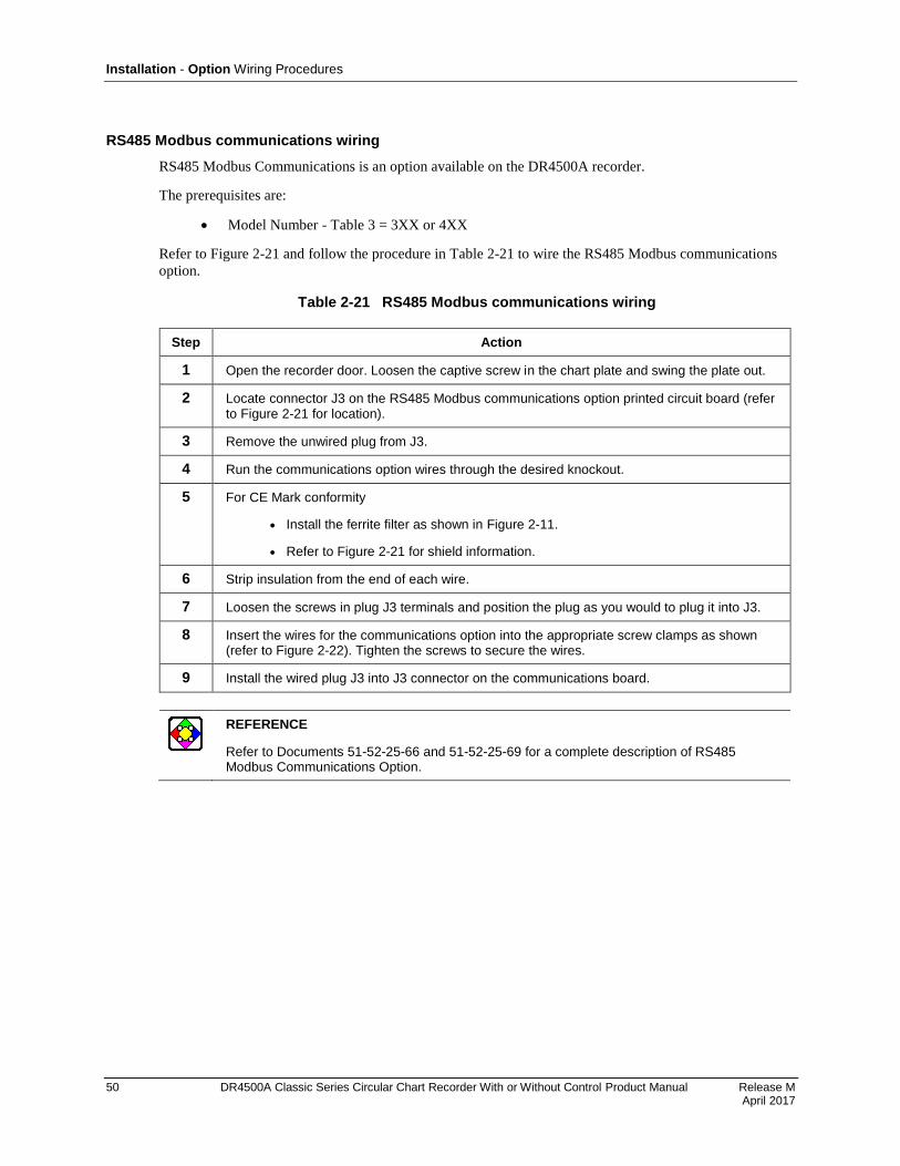
Installation - Option Wiring Procedures
50 DR4500A Classic Series Circular Chart Recorder With or Without Control Product Manual Release M April 2017
RS485 Modbus communications wiring
RS485 Modbus Communications is an option available on the DR4500A recorder.
The prerequisites are:
Model Number - Table 3 = 3XX or 4XX
Refer to Figure 2-21 and follow the procedure in Table 2-21 to wire the RS485 Modbus communications
option.
Table 2-21 RS485 Modbus communications wiring
Step Action
1 Open the recorder door. Loosen the captive screw in the chart plate and swing the plate out.
2 Locate connector J3 on the RS485 Modbus communications option printed circuit board (refer to Figure 2-21 for location).
3 Remove the unwired plug from J3.
4 Run the communications option wires through the desired knockout.
5 For CE Mark conformity
Install the ferrite filter as shown in Figure 2-11.
Refer to Figure 2-21 for shield information.
6 Strip insulation from the end of each wire.
7 Loosen the screws in plug J3 terminals and position the plug as you would to plug it into J3.
8 Insert the wires for the communications option into the appropriate screw clamps as shown (refer to Figure 2-22). Tighten the screws to secure the wires.
9 Install the wired plug J3 into J3 connector on the communications board.
REFERENCE
Refer to Documents 51-52-25-66 and 51-52-25-69 for a complete description of RS485 Modbus Communications Option.

Installation - Option Wiring Procedures
Release M DR4500A Classic Series Circular Chart Recorder With or Without Control Product Manual 51 April 2017
Figure 2-21 RS485 Modbus communications wiring
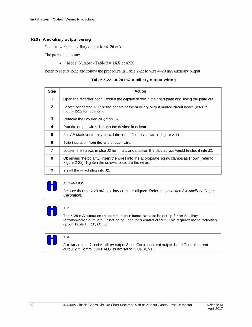
Installation - Option Wiring Procedures
52 DR4500A Classic Series Circular Chart Recorder With or Without Control Product Manual Release M April 2017
4-20 mA auxiliary output wiring
You can wire an auxiliary output for 4–20 mA.
The prerequisites are:
Model Number - Table 3 = 1XX or 4XX
Refer to Figure 2-22 and follow the procedure in Table 2-22 to wire 4–20 mA auxiliary output.
Table 2-22 4-20 mA auxiliary output wiring
Step Action
1 Open the recorder door. Loosen the captive screw in the chart plate and swing the plate out.
2 Locate connector J2 near the bottom of the auxiliary output printed circuit board (refer to Figure 2-22 for location).
3 Remove the unwired plug from J2.
4 Run the output wires through the desired knockout.
5 For CE Mark conformity, install the ferrite filter as shown in Figure 2-11.
6 Strip insulation from the end of each wire.
7 Loosen the screws in plug J2 terminals and position the plug as you would to plug it into J2.
8 Observing the polarity, insert the wires into the appropriate screw clamps as shown (refer to Figure 2-22). Tighten the screws to secure the wires.
9 Install the wired plug into J2.
ATTENTION
Be sure that the 4-20 mA auxiliary output is aligned. Refer to subsection 8.4 Auxiliary Output Calibration.
TIP
The 4-20 mA output on the control output board can also be set up for an Auxiliary retransmission output if it is not being used for a control output. This requires model selection option Table II = 10, 60, 66.
TIP
Auxiliary output 2 and Auxiliary output 3 use Control current output 1 and Control current output 2 if Control “OUT ALG” is not set to “CURRENT”.
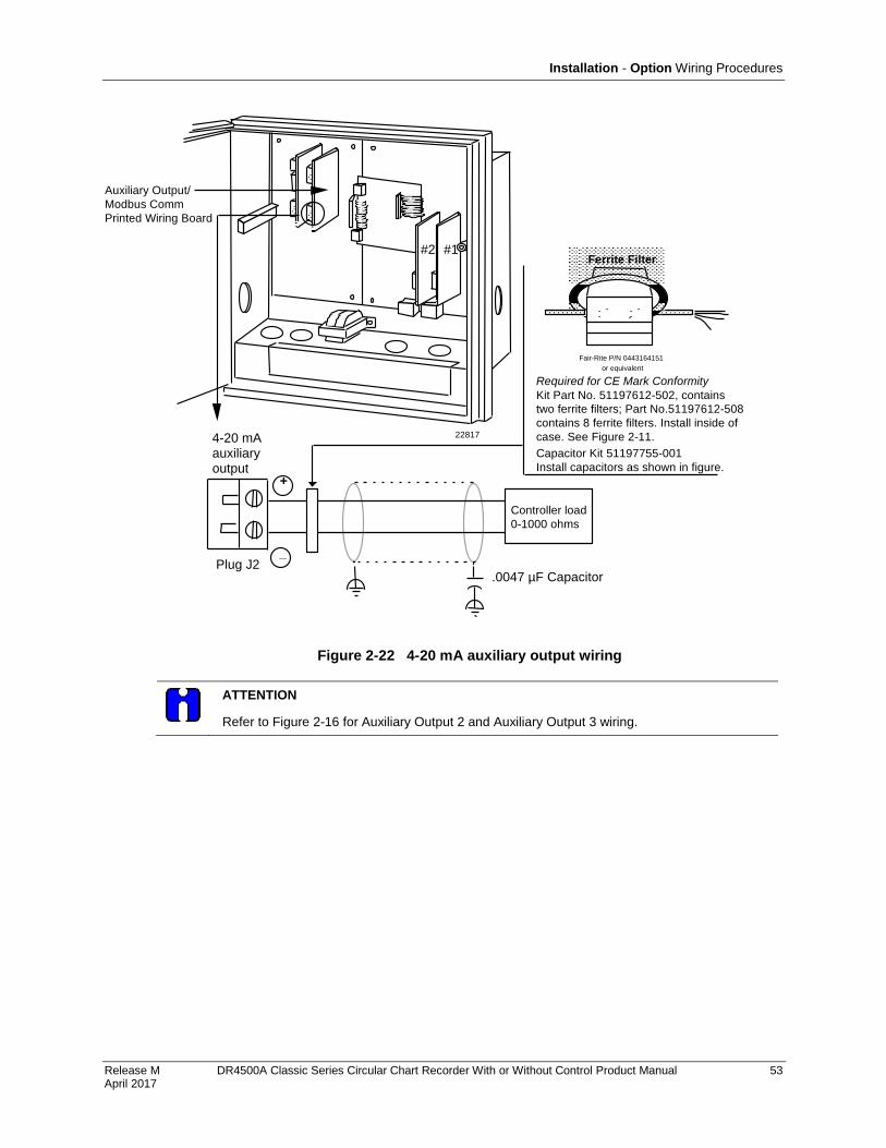
Installation - Option Wiring Procedures
Release M DR4500A Classic Series Circular Chart Recorder With or Without Control Product Manual 53 April 2017
#2 #1
22817
Auxiliary Output/
Modbus Comm
Printed Wiring Board
+
_
4-20 mA auxiliary output
Plug J2
Fair-Rite P/N 0443164151
or equivalent
Ferrite Filter
.0047 µF Capacitor
Controller load
0-1000 ohms
Capacitor Kit 51197755-001
Install capacitors as shown in figure.
Required for CE Mark Conformity
Kit Part No. 51197612-502, contains
two ferrite filters; Part No.51197612-508
contains 8 ferrite filters. Install inside of
case. See Figure 2-11.
Figure 2-22 4-20 mA auxiliary output wiring
ATTENTION
Refer to Figure 2-16 for Auxiliary Output 2 and Auxiliary Output 3 wiring.
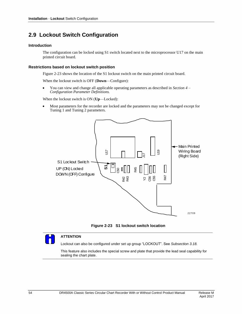
Installation - Lockout Switch Configuration
54 DR4500A Classic Series Circular Chart Recorder With or Without Control Product Manual Release M April 2017
2.9 Lockout Switch Configuration
Introduction
The configuration can be locked using S1 switch located next to the microprocessor U17 on the main
printed circuit board.
Restrictions based on lockout switch position
Figure 2-23 shows the location of the S1 lockout switch on the main printed circuit board.
When the lockout switch is OFF (Down—Configure):
You can view and change all applicable operating parameters as described in Section 4 – Configuration Parameter Definitions.
When the lockout switch is ON (Up—Locked):
Most parameters for the recorder are locked and the parameters may not be changed except for Tuning 1 and Tuning 2 parameters.
U17
S1
U19
J17
R47
C55
C56
Y2
R45
R43
R42
C50UP (ON) Locked
DOWN (OFF) Configure
Main Printed
Wiring Board
(Right Side)
S1 Lockout Switch
22709
Figure 2-23 S1 lockout switch location
ATTENTION
Lockout can also be configured under set up group “LOCKOUT”. See Subsection 3.18.
This feature also includes the special screw and plate that provide the lead seal capability for sealing the chart plate.
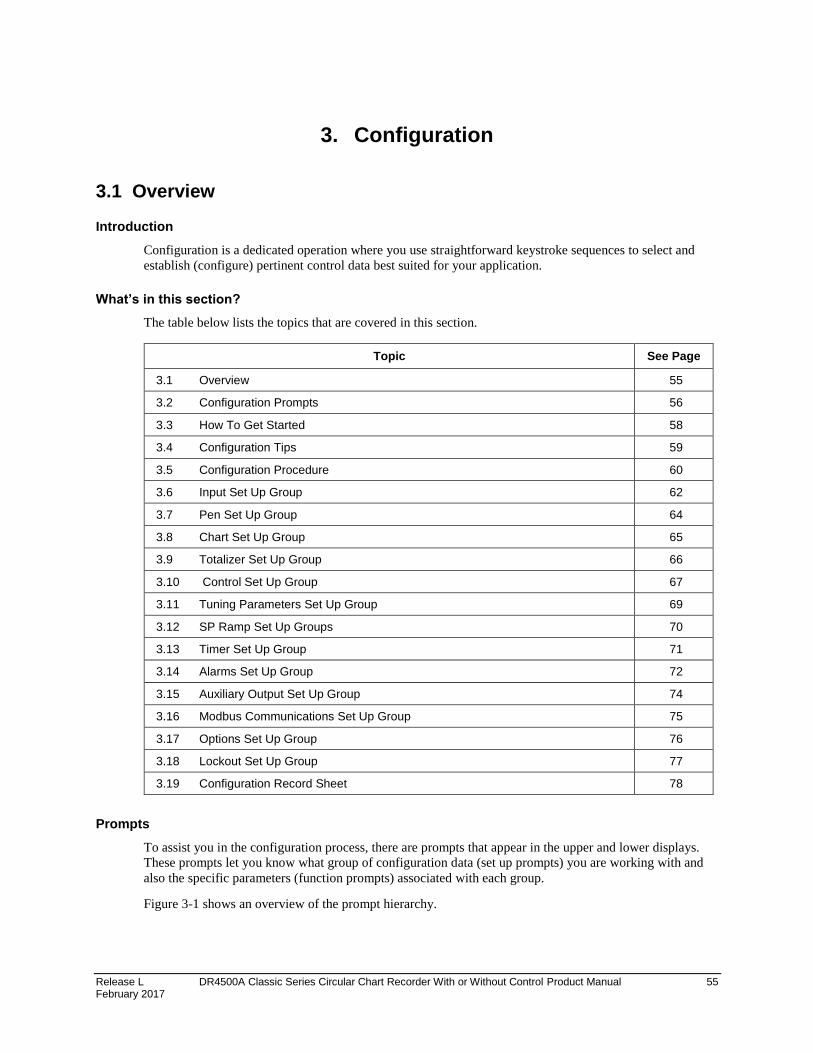
Release L DR4500A Classic Series Circular Chart Recorder With or Without Control Product Manual 55 February 2017
3. Configuration
3.1 Overview
Introduction
Configuration is a dedicated operation where you use straightforward keystroke sequences to select and
establish (configure) pertinent control data best suited for your application.
What’s in this section?
The table below lists the topics that are covered in this section.
Topic See Page
3.1 Overview 55
3.2 Configuration Prompts 56
3.3 How To Get Started 58
3.4 Configuration Tips 59
3.5 Configuration Procedure 60
3.6 Input Set Up Group 62
3.7 Pen Set Up Group 64
3.8 Chart Set Up Group 65
3.9 Totalizer Set Up Group 66
3.10 Control Set Up Group 67
3.11 Tuning Parameters Set Up Group 69
3.12 SP Ramp Set Up Groups 70
3.13 Timer Set Up Group 71
3.14 Alarms Set Up Group 72
3.15 Auxiliary Output Set Up Group 74
3.16 Modbus Communications Set Up Group 75
3.17 Options Set Up Group 76
3.18 Lockout Set Up Group 77
3.19 Configuration Record Sheet 78
Prompts
To assist you in the configuration process, there are prompts that appear in the upper and lower displays.
These prompts let you know what group of configuration data (set up prompts) you are working with and
also the specific parameters (function prompts) associated with each group.
Figure 3-1 shows an overview of the prompt hierarchy.

Configuration Configuration Prompts
56 DR4500A Classic Series Circular Chart Recorder With or Without Control Product Manual Release M April 2017
3.2 Configuration Prompts
Diagram: prompt hierarchy
Figure 3-1 shows an overview of the DR4500A Set Up prompts and their associated Function prompt - read
from left to right.
Figure 3-1 DR4500A prompt hierarchy
Set Up Group Function Prompts
INPUT 1 ENABLE DECIMAL UNITS ENGUNITS IN1 TYPE XMITTER IN1 HI
IN1 LO CUTOFF 1 INPTCOMP FILTER1 BURNOUT EMISSIV
INPUT 2 Same as INPUT 1
PEN 1 ENABLE PEN 1 IN CHART1HI CHART1LO PEN1ON PEN1OFF
PEN 2 Same as PEN 1
CHART CHRTSPD HOUR/REV LINEARIZ
TOTAL 1 (Value) RSET TOT TOTAL 1 TOTAL EU RATE SCALER RSETABLE
INHIBIT
TOTAL 2 Same as TOTAL 1
CONTROL 1 ENABLE PID SETS SW VALUE SP SOURC RATIO BIAS SP TRACK
POWER UP SP HILIM SP LOLIM ACTION OUT HILIM OUT LOLIM DROPOFF
DEADBAND OUT HYST FAILSAFE REM SW MAN KEY PBorGAIN MINorRPM
CONT1ALG OUT1ALG 4-20 RNG
CONTROL 2 Same as CONTROL 1
TUNING 1 FUZZY ACCUTUNE AT ERR PROP BD or
GAIN
RATE MIN RSET MIN or
RSET RPM
MAN RSET
PROP BD2 or
GAIN 2
RATE2MIN RSET2MIN or
RSET2RPM
CYC SEC CYC2SEC
TUNING 2 Same as TUNING 1
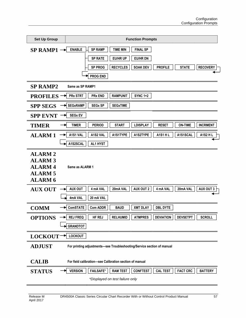
Configuration Configuration Prompts
Release M DR4500A Classic Series Circular Chart Recorder With or Without Control Product Manual 57 April 2017
Set Up Group Function Prompts
SP RAMP1 ENABLE SP RAMP TIME MIN FINAL SP
SP RATE EU/HR UP EU/HR DN
SP PROG RECYCLES SOAK DEV PROFILE STATE RECOVERY
PROG END
SP RAMP2 Same as SP RAMP1
PROFILES PRx STRT PRx END RAMPUNIT SYNC 1+2
SPP SEGS SEGxRAMP SEGx SP SEGxTIME
SPP EVNT SEGx EV
TIMER TIMER PERIOD START LDISPLAY RESET ON-TIME INCRMENT
ALARM 1 A1S1 VAL A1S2 VAL A1S1TYPE A1S2TYPE A1S1 H L A1S1SCAL A1S2 H L
A1S2SCAL AL1 HYST
ALARM 2
ALARM 3
ALARM 4
ALARM 5
ALARM 6
Same as ALARM 1
AUX OUT AUX OUT 4 mA VAL 20mA VAL AUX OUT 2 4 mA VAL 20mA VAL AUX OUT 3
4mA VAL 20 mA VAL
COMM ComSTATE Com ADDR BAUD XMT DLAY DBL DYTE
OPTIONS REJ FREQ HF REJ RELHUMID ATMPRES DEVIATION DEVSETPT SCROLL
GRANDTOT
LOCKOUT LOCKOUT
ADJUST For printing adjustments—see Troubleshooting/Service section of manual
CALIB For field calibration—see Calibration section of manual
STATUS VERSION FAILSAFE* RAM TEST CONFTEST CAL TEST FACT CRC BATTERY
*Displayed on test failure only
Configuration How To Get Started
58 DR4500A Classic Series Circular Chart Recorder With or Without Control Product Manual Release M April 2017
3.3 How To Get Started
Read the configuration tips
Read subsection 3.4 Configuration Tips which will help you to easily and quickly configure your recorder.
Read configuration procedure
Read subsection 3.5 Configuration Procedure which tells you how to access the Set Up groups, and the
function parameters within each of these groups that are shown in the Prompt Hierarchy in Figure 3-1.
Set Up groups
The Set Up groups and function parameters are listed in the order of their appearance. The list includes the
name of the prompt, the range of setting or selections available, and the factory setting. It allows you to
quickly find a parameter and obtain the available range or selection you require.
Parameter explanations or definitions
If you need a detailed explanation of any prompt listed, refer to Section 4 – Configuration Parameter
Definitions. This section lists the set up and function prompts, the selections or range of settings that you
can make for each, plus a detailed explanation or definition of each parameter.
Configuration record sheet
Located in subsection 3.19 is a Configuration Record Sheet. When you make your configuration selections,
record them on this sheet. Then you will have a record of how the recorder was configured.
Set up the recorder in this order:
Inputs (Display will be correct)
Pens
Chart
Alarms
Control
Tuning
Other functions as needed
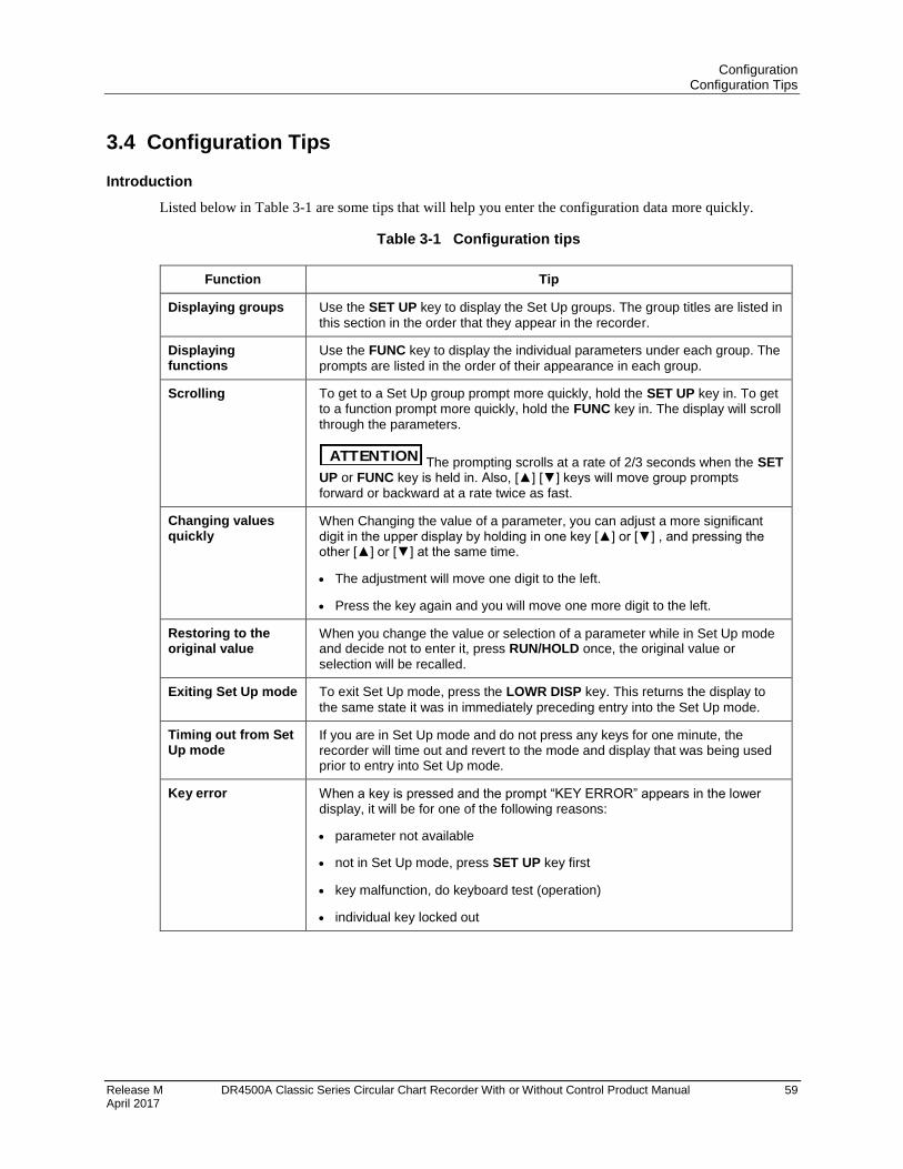
Configuration Configuration Tips
Release M DR4500A Classic Series Circular Chart Recorder With or Without Control Product Manual 59 April 2017
3.4 Configuration Tips
Introduction
Listed below in Table 3-1 are some tips that will help you enter the configuration data more quickly.
Table 3-1 Configuration tips
Function Tip
Displaying groups Use the SET UP key to display the Set Up groups. The group titles are listed in
this section in the order that they appear in the recorder.
Displaying functions
Use the FUNC key to display the individual parameters under each group. The
prompts are listed in the order of their appearance in each group.
Scrolling To get to a Set Up group prompt more quickly, hold the SET UP key in. To get to a function prompt more quickly, hold the FUNC key in. The display will scroll
through the parameters.
ATTENTION The prompting scrolls at a rate of 2/3 seconds when the SET UP or FUNC key is held in. Also, [] [] keys will move group prompts
forward or backward at a rate twice as fast.
Changing values quickly
When Changing the value of a parameter, you can adjust a more significant digit in the upper display by holding in one key [] or [] , and pressing the other [] or [] at the same time.
The adjustment will move one digit to the left.
Press the key again and you will move one more digit to the left.
Restoring to the original value
When you change the value or selection of a parameter while in Set Up mode and decide not to enter it, press RUN/HOLD once, the original value or
selection will be recalled.
Exiting Set Up mode To exit Set Up mode, press the LOWR DISP key. This returns the display to
the same state it was in immediately preceding entry into the Set Up mode.
Timing out from Set Up mode
If you are in Set Up mode and do not press any keys for one minute, the recorder will time out and revert to the mode and display that was being used prior to entry into Set Up mode.
Key error When a key is pressed and the prompt “KEY ERROR” appears in the lower display, it will be for one of the following reasons:
parameter not available
not in Set Up mode, press SET UP key first
key malfunction, do keyboard test (operation)
individual key locked out
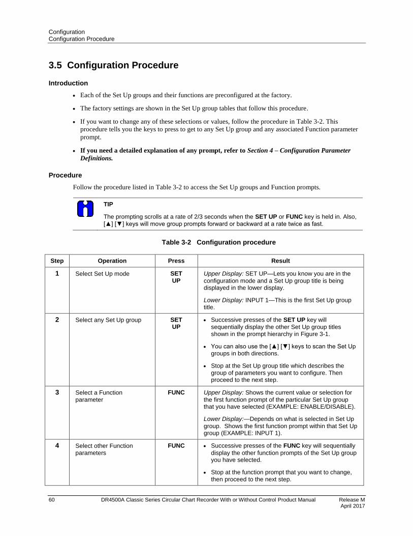
Configuration Configuration Procedure
60 DR4500A Classic Series Circular Chart Recorder With or Without Control Product Manual Release M April 2017
3.5 Configuration Procedure
Introduction
Each of the Set Up groups and their functions are preconfigured at the factory.
The factory settings are shown in the Set Up group tables that follow this procedure.
If you want to change any of these selections or values, follow the procedure in Table 3-2. This
procedure tells you the keys to press to get to any Set Up group and any associated Function parameter
prompt.
If you need a detailed explanation of any prompt, refer to Section 4 – Configuration Parameter
Definitions.
Procedure
Follow the procedure listed in Table 3-2 to access the Set Up groups and Function prompts.
TIP
The prompting scrolls at a rate of 2/3 seconds when the SET UP or FUNC key is held in. Also,
[] [] keys will move group prompts forward or backward at a rate twice as fast.
Table 3-2 Configuration procedure
Step Operation Press Result
1 Select Set Up mode SET UP
Upper Display: SET UP—Lets you know you are in the
configuration mode and a Set Up group title is being displayed in the lower display.
Lower Display: INPUT 1—This is the first Set Up group title.
2 Select any Set Up group SET UP
Successive presses of the SET UP key will
sequentially display the other Set Up group titles shown in the prompt hierarchy in Figure 3-1.
You can also use the [] [] keys to scan the Set Up groups in both directions.
Stop at the Set Up group title which describes the group of parameters you want to configure. Then proceed to the next step.
3 Select a Function parameter
FUNC Upper Display: Shows the current value or selection for
the first function prompt of the particular Set Up group that you have selected (EXAMPLE: ENABLE/DISABLE).
Lower Display:—Depends on what is selected in Set Up
group. Shows the first function prompt within that Set Up group (EXAMPLE: INPUT 1).
4 Select other Function parameters
FUNC Successive presses of the FUNC key will sequentially
display the other function prompts of the Set Up group you have selected.
Stop at the function prompt that you want to change, then proceed to the next step.
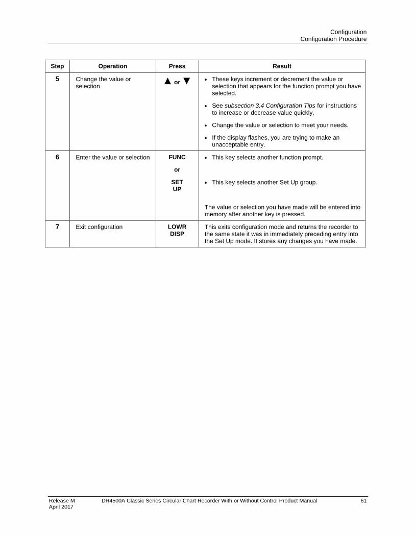
Configuration Configuration Procedure
Release M DR4500A Classic Series Circular Chart Recorder With or Without Control Product Manual 61 April 2017
Step Operation Press Result
5 Change the value or selection
or These keys increment or decrement the value or
selection that appears for the function prompt you have selected.
See subsection 3.4 Configuration Tips for instructions to increase or decrease value quickly.
Change the value or selection to meet your needs.
If the display flashes, you are trying to make an unacceptable entry.
6 Enter the value or selection FUNC
or
SET UP
This key selects another function prompt.
This key selects another Set Up group.
The value or selection you have made will be entered into memory after another key is pressed.
7 Exit configuration LOWR DISP
This exits configuration mode and returns the recorder to the same state it was in immediately preceding entry into the Set Up mode. It stores any changes you have made.
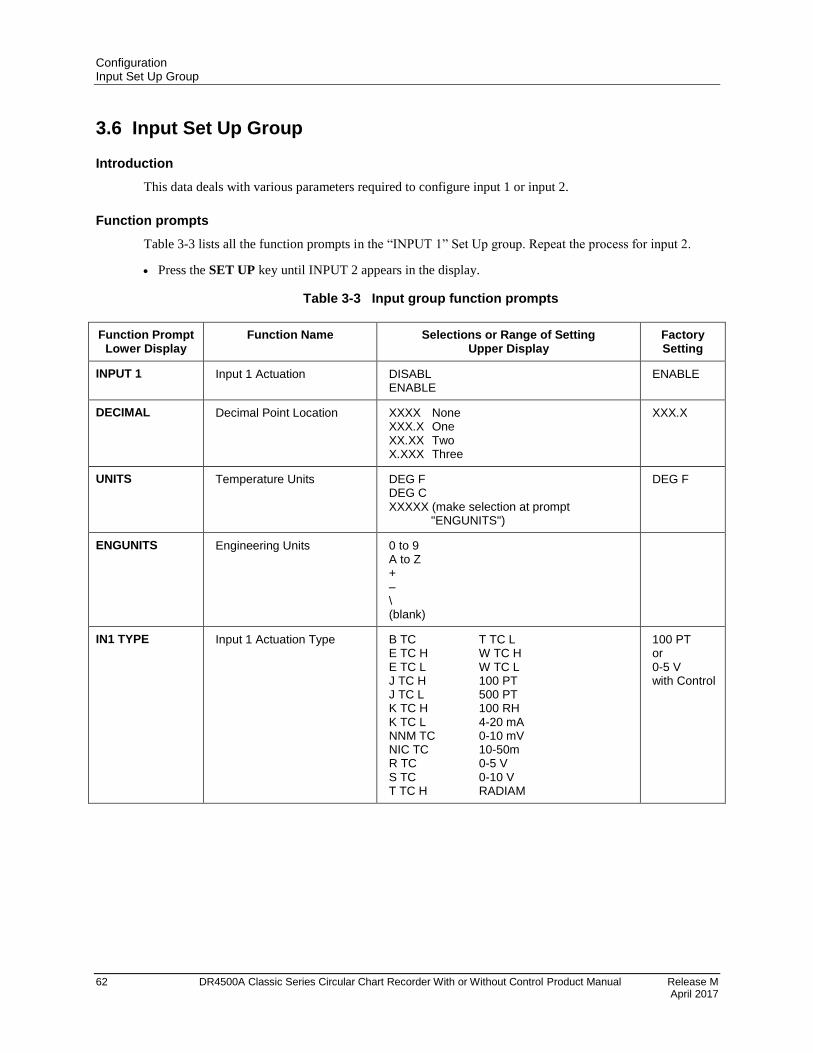
Configuration Input Set Up Group
62 DR4500A Classic Series Circular Chart Recorder With or Without Control Product Manual Release M April 2017
3.6 Input Set Up Group
Introduction
This data deals with various parameters required to configure input 1 or input 2.
Function prompts
Table 3-3 lists all the function prompts in the “INPUT 1” Set Up group. Repeat the process for input 2.
Press the SET UP key until INPUT 2 appears in the display.
Table 3-3 Input group function prompts
Function Prompt Lower Display
Function Name Selections or Range of Setting Upper Display
Factory Setting
INPUT 1 Input 1 Actuation DISABL ENABLE
ENABLE
DECIMAL Decimal Point Location XXXX None XXX.X One XX.XX Two X.XXX Three
XXX.X
UNITS Temperature Units DEG F DEG C XXXXX (make selection at prompt "ENGUNITS")
DEG F
ENGUNITS Engineering Units 0 to 9 A to Z + – \ (blank)
IN1 TYPE Input 1 Actuation Type B TC T TC L E TC H W TC H E TC L W TC L J TC H 100 PT J TC L 500 PT K TC H 100 RH K TC L 4-20 mA NNM TC 0-10 mV NIC TC 10-50m R TC 0-5 V S TC 0-10 V T TC H RADIAM
100 PT or 0-5 V with Control
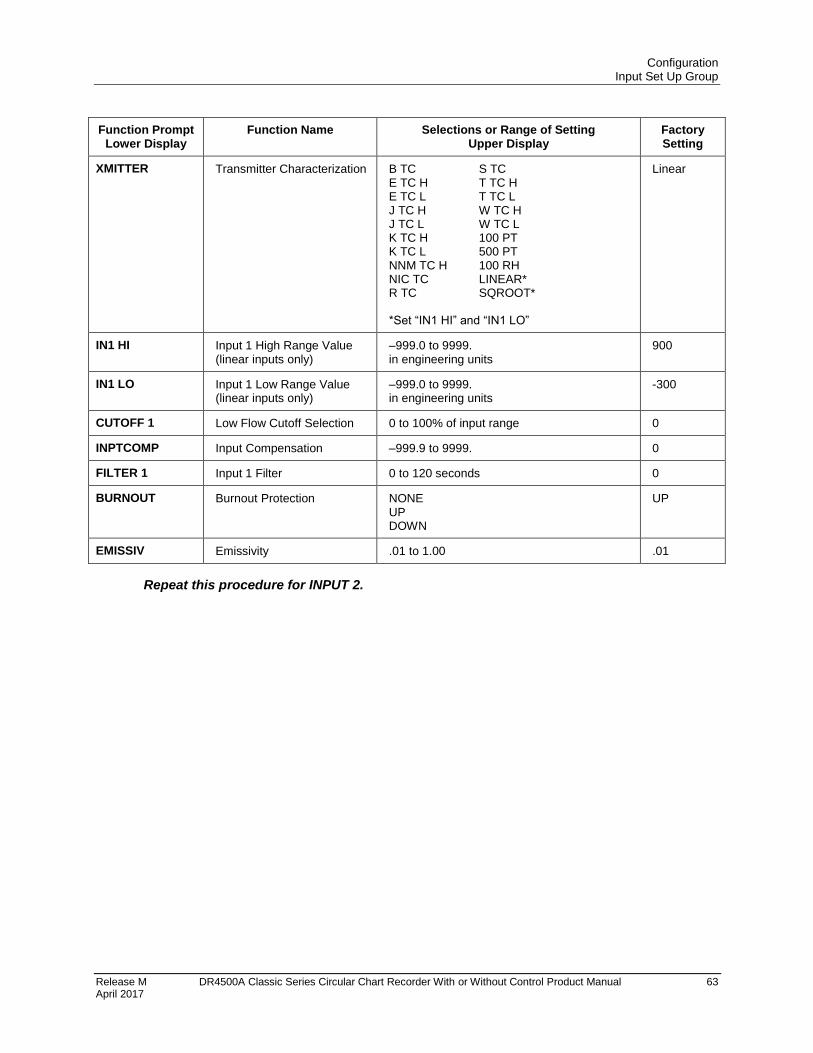
Configuration Input Set Up Group
Release M DR4500A Classic Series Circular Chart Recorder With or Without Control Product Manual 63 April 2017
Function Prompt Lower Display
Function Name Selections or Range of Setting Upper Display
Factory Setting
XMITTER Transmitter Characterization B TC S TC E TC H T TC H E TC L T TC L J TC H W TC H J TC L W TC L K TC H 100 PT K TC L 500 PT NNM TC H 100 RH NIC TC LINEAR* R TC SQROOT* *Set “IN1 HI” and “IN1 LO”
Linear
IN1 HI Input 1 High Range Value (linear inputs only)
–999.0 to 9999. in engineering units
900
IN1 LO Input 1 Low Range Value (linear inputs only)
–999.0 to 9999. in engineering units
-300
CUTOFF 1 Low Flow Cutoff Selection 0 to 100% of input range 0
INPTCOMP Input Compensation –999.9 to 9999. 0
FILTER 1 Input 1 Filter 0 to 120 seconds 0
BURNOUT Burnout Protection NONE UP DOWN
UP
EMISSIV Emissivity .01 to 1.00 .01
Repeat this procedure for INPUT 2.
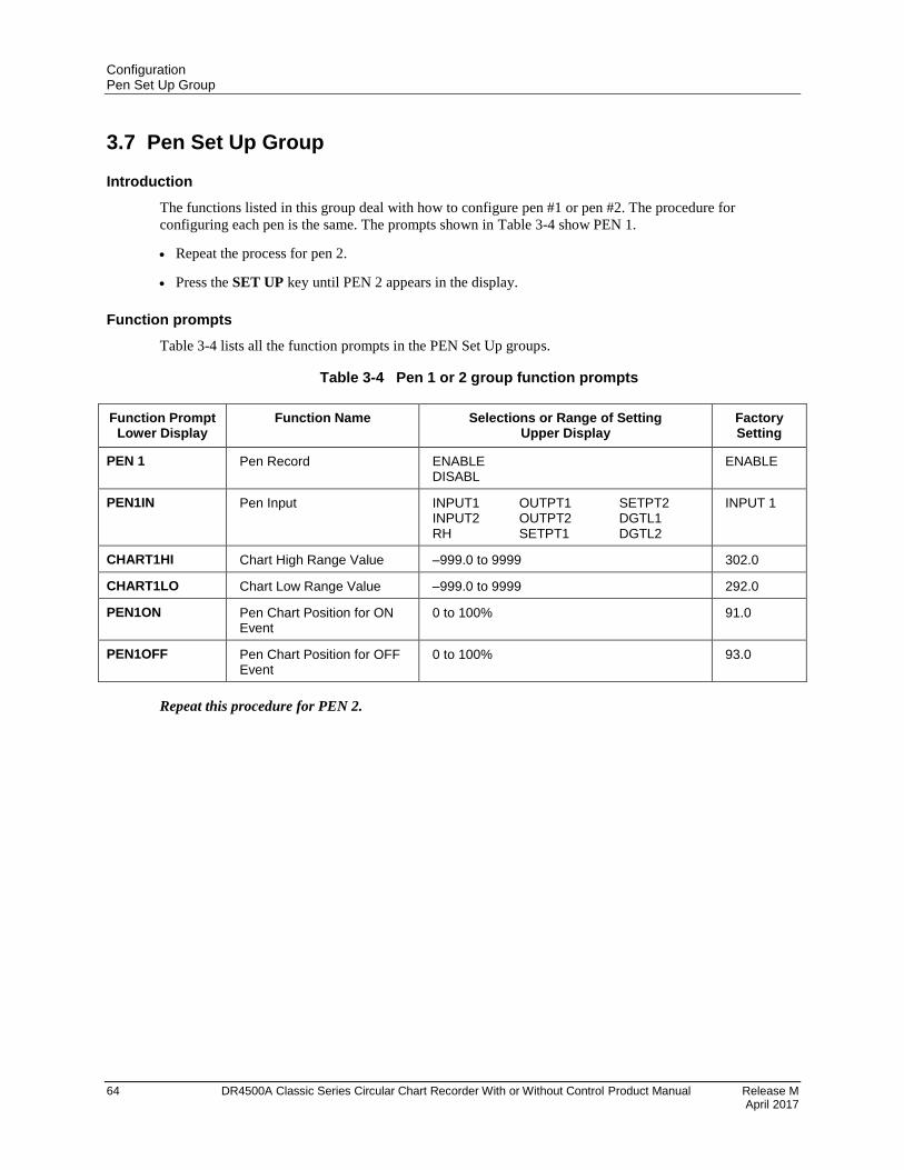
Configuration Pen Set Up Group
64 DR4500A Classic Series Circular Chart Recorder With or Without Control Product Manual Release M April 2017
3.7 Pen Set Up Group
Introduction
The functions listed in this group deal with how to configure pen #1 or pen #2. The procedure for
configuring each pen is the same. The prompts shown in Table 3-4 show PEN 1.
Repeat the process for pen 2.
Press the SET UP key until PEN 2 appears in the display.
Function prompts
Table 3-4 lists all the function prompts in the PEN Set Up groups.
Table 3-4 Pen 1 or 2 group function prompts
Function Prompt Lower Display
Function Name Selections or Range of Setting Upper Display
Factory Setting
PEN 1 Pen Record ENABLE DISABL
ENABLE
PEN1IN Pen Input INPUT1 OUTPT1 SETPT2 INPUT2 OUTPT2 DGTL1 RH SETPT1 DGTL2
INPUT 1
CHART1HI Chart High Range Value –999.0 to 9999 302.0
CHART1LO Chart Low Range Value –999.0 to 9999 292.0
PEN1ON Pen Chart Position for ON Event
0 to 100% 91.0
PEN1OFF Pen Chart Position for OFF Event
0 to 100% 93.0
Repeat this procedure for PEN 2.
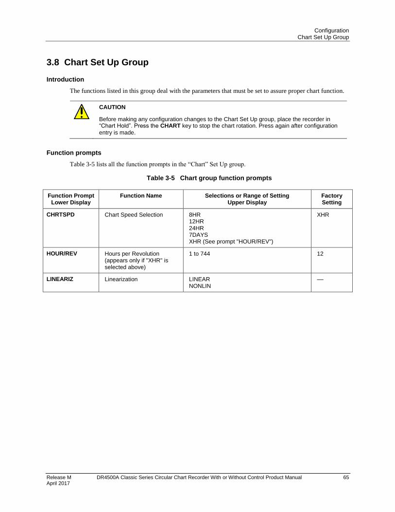
Configuration Chart Set Up Group
Release M DR4500A Classic Series Circular Chart Recorder With or Without Control Product Manual 65 April 2017
3.8 Chart Set Up Group
Introduction
The functions listed in this group deal with the parameters that must be set to assure proper chart function.
CAUTION
Before making any configuration changes to the Chart Set Up group, place the recorder in “Chart Hold”. Press the CHART key to stop the chart rotation. Press again after configuration
entry is made.
Function prompts
Table 3-5 lists all the function prompts in the “Chart” Set Up group.
Table 3-5 Chart group function prompts
Function Prompt Lower Display
Function Name Selections or Range of Setting Upper Display
Factory Setting
CHRTSPD Chart Speed Selection 8HR 12HR 24HR 7DAYS XHR (See prompt "HOUR/REV")
XHR
HOUR/REV Hours per Revolution (appears only if "XHR" is selected above)
1 to 744 12
LINEARIZ Linearization LINEAR NONLIN
––
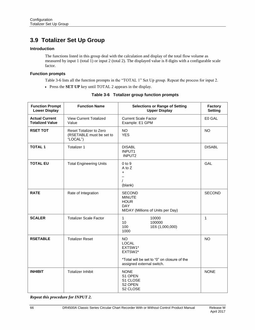
Configuration Totalizer Set Up Group
66 DR4500A Classic Series Circular Chart Recorder With or Without Control Product Manual Release M April 2017
3.9 Totalizer Set Up Group
Introduction
The functions listed in this group deal with the calculation and display of the total flow volume as
measured by input 1 (total 1) or input 2 (total 2). The displayed value is 8 digits with a configurable scale
factor.
Function prompts
Table 3-6 lists all the function prompts in the “TOTAL 1” Set Up group. Repeat the process for input 2.
Press the SET UP key until TOTAL 2 appears in the display.
Table 3-6 Totalizer group function prompts
Function Prompt Lower Display
Function Name Selections or Range of Setting Upper Display
Factory Setting
Actual Current Totalized Value
View Current Totalized Value
Current Scale Factor Example: E1 GPM
E0 GAL
RSET TOT Reset Totalizer to Zero (RSETABLE must be set to “LOCAL”)
NO YES
NO
TOTAL 1 Totalizer 1 DISABL INPUT1 INPUT2
DISABL
TOTAL EU Total Engineering Units 0 to 9 A to Z + – / (blank)
GAL
RATE Rate of Integration SECOND MINUTE HOUR DAY M/DAY (Millions of Units per Day)
SECOND
SCALER Totalizer Scale Factor 1 10000 10 100000 100 1E6 (1,000,000) 1000
1
RSETABLE Totalizer Reset NO LOCAL EXTSW1* EXTSW2*
*Total will be set to “0” on closure of the assigned external switch.
NO
INHIBIT Totalizer Inhibit NONE S1 OPEN S1 CLOSE S2 OPEN S2 CLOSE
NONE
Repeat this procedure for INPUT 2.
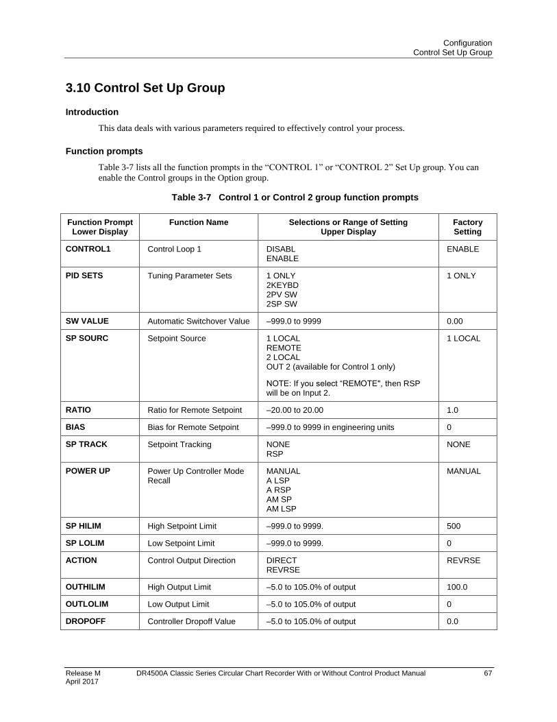
Configuration Control Set Up Group
Release M DR4500A Classic Series Circular Chart Recorder With or Without Control Product Manual 67 April 2017
3.10 Control Set Up Group
Introduction
This data deals with various parameters required to effectively control your process.
Function prompts
Table 3-7 lists all the function prompts in the “CONTROL 1” or “CONTROL 2” Set Up group. You can
enable the Control groups in the Option group.
Table 3-7 Control 1 or Control 2 group function prompts
Function Prompt Lower Display
Function Name Selections or Range of Setting Upper Display
Factory Setting
CONTROL1 Control Loop 1 DISABL ENABLE
ENABLE
PID SETS Tuning Parameter Sets 1 ONLY 2KEYBD 2PV SW 2SP SW
1 ONLY
SW VALUE Automatic Switchover Value –999.0 to 9999 0.00
SP SOURC Setpoint Source 1 LOCAL REMOTE 2 LOCAL OUT 2 (available for Control 1 only)
NOTE: If you select “REMOTE", then RSP will be on Input 2.
1 LOCAL
RATIO Ratio for Remote Setpoint –20.00 to 20.00 1.0
BIAS Bias for Remote Setpoint –999.0 to 9999 in engineering units 0
SP TRACK Setpoint Tracking NONE RSP
NONE
POWER UP Power Up Controller Mode Recall
MANUAL A LSP A RSP AM SP AM LSP
MANUAL
SP HILIM High Setpoint Limit –999.0 to 9999. 500
SP LOLIM Low Setpoint Limit –999.0 to 9999. 0
ACTION Control Output Direction DIRECT REVRSE
REVRSE
OUTHILIM High Output Limit –5.0 to 105.0% of output 100.0
OUTLOLIM Low Output Limit –5.0 to 105.0% of output 0
DROPOFF Controller Dropoff Value –5.0 to 105.0% of output 0.0
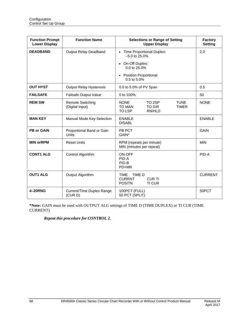
Configuration Control Set Up Group
68 DR4500A Classic Series Circular Chart Recorder With or Without Control Product Manual Release M April 2017
Function Prompt Lower Display
Function Name Selections or Range of Setting Upper Display
Factory Setting
DEADBAND Output Relay Deadband Time Proportional Duplex: –5.0 to 25.0%
On-Off Duplex: 0.0 to 25.0%
Position Proportional 0.5 to 5.0%
2.0
OUT HYST Output Relay Hysteresis 0.0 to 5.0% of PV Span 0.5
FAILSAFE Failsafe Output Value 0 to 100% 50
REM SW Remote Switching (Digital Input)
NONE TO 2SP TUNE TO MAN TO DIR TIMER TO LSP RN/HLD
NONE
MAN KEY Manual Mode Key Selection ENABLE DISABL
ENABLE
PB or GAIN Proportional Band or Gain Units
PB PCT GAIN*
GAIN
MIN orRPM Reset Units RPM (repeats per minute) MIN (minutes per repeat)
MIN
CONT1 ALG Control Algorithm ON-OFF PID-A PID-B PD+MR
PID-A
OUT1 ALG Output Algorithm TIME TIME D CURRNT CUR TI POSITN TI CUR
CURRENT
4–20RNG Current/Time Duplex Range (CUR D)
100PCT (FULL) 50 PCT (SPLIT)
50PCT
*Note: GAIN must be used with OUTPUT ALG settings of TIME D (TIME DUPLEX) or TI CUR (TIME
CURRENT)
Repeat this procedure for CONTROL 2.
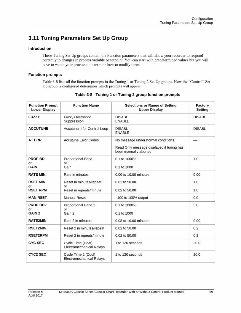
Configuration Tuning Parameters Set Up Group
Release M DR4500A Classic Series Circular Chart Recorder With or Without Control Product Manual 69 April 2017
3.11 Tuning Parameters Set Up Group
Introduction
These Tuning Set Up groups contain the Function parameters that will allow your recorder to respond
correctly to changes in process variable or setpoint. You can start with predetermined values but you will
have to watch your process to determine how to modify them.
Function prompts
Table 3-8 lists all the function prompts in the Tuning 1 or Tuning 2 Set Up groups. How the “Control” Set
Up group is configured determines which prompts will appear.
Table 3-8 Tuning 1 or Tuning 2 group function prompts
Function Prompt Lower Display
Function Name Selections or Range of Setting Upper Display
Factory Setting
FUZZY Fuzzy Overshoot Suppression
DISABL ENABLE
DISABL
ACCUTUNE Accutune II for Control Loop DISABL ENABLE
DISABL
AT ERR Accutune Error Codes No message under normal conditions
Read Only message displayed if tuning has been manually aborted
––
PROP BD
or GAIN
Proportional Band or Gain
0.1 to 1000% 0.1 to 1000
1.0
RATE MIN Rate in minutes 0.00 to 10.00 minutes 0.00
RSET MIN
or RSET RPM
Reset in minutes/repeat or Reset in repeats/minute
0.02 to 50.00 0.02 to 50.00
1.0 1.0
MAN RSET Manual Reset –100 to 100% output 0.0
PROP BD2
or GAIN 2
Proportional Band 2 or Gain 2
0.1 to 1000% 0.1 to 1000
5.0
RATE2MIN Rate 2 in minutes 0.08 to 10.00 minutes 0.00
RSET2MIN
RSET2RPM
Reset 2 in minutes/repeat
Reset 2 in repeats/minute
0.02 to 50.00
0.02 to 50.00
0.2
0.2
CYC SEC Cycle Time (Heat) Electromechanical Relays
1 to 120 seconds 20.0
CYC2 SEC Cycle Time 2 (Cool) Electromechanical Relays
1 to 120 seconds 20.0
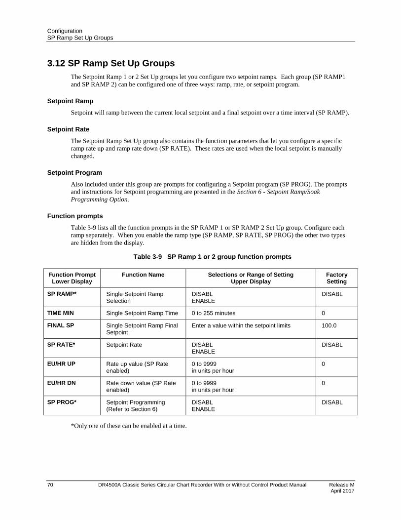
Configuration SP Ramp Set Up Groups
70 DR4500A Classic Series Circular Chart Recorder With or Without Control Product Manual Release M April 2017
3.12 SP Ramp Set Up Groups
The Setpoint Ramp 1 or 2 Set Up groups let you configure two setpoint ramps. Each group (SP RAMP1
and SP RAMP 2) can be configured one of three ways: ramp, rate, or setpoint program.
Setpoint Ramp
Setpoint will ramp between the current local setpoint and a final setpoint over a time interval (SP RAMP).
Setpoint Rate
The Setpoint Ramp Set Up group also contains the function parameters that let you configure a specific
ramp rate up and ramp rate down (SP RATE). These rates are used when the local setpoint is manually
changed.
Setpoint Program
Also included under this group are prompts for configuring a Setpoint program (SP PROG). The prompts
and instructions for Setpoint programming are presented in the Section 6 - Setpoint Ramp/Soak
Programming Option.
Function prompts
Table 3-9 lists all the function prompts in the SP RAMP 1 or SP RAMP 2 Set Up group. Configure each
ramp separately. When you enable the ramp type (SP RAMP, SP RATE, SP PROG) the other two types
are hidden from the display.
Table 3-9 SP Ramp 1 or 2 group function prompts
Function Prompt Lower Display
Function Name Selections or Range of Setting Upper Display
Factory Setting
SP RAMP* Single Setpoint Ramp Selection
DISABL ENABLE
DISABL
TIME MIN Single Setpoint Ramp Time 0 to 255 minutes 0
FINAL SP Single Setpoint Ramp Final Setpoint
Enter a value within the setpoint limits 100.0
SP RATE* Setpoint Rate DISABL ENABLE
DISABL
EU/HR UP Rate up value (SP Rate enabled)
0 to 9999 in units per hour
0
EU/HR DN Rate down value (SP Rate enabled)
0 to 9999 in units per hour
0
SP PROG* Setpoint Programming (Refer to Section 6)
DISABL ENABLE
DISABL
*Only one of these can be enabled at a time.
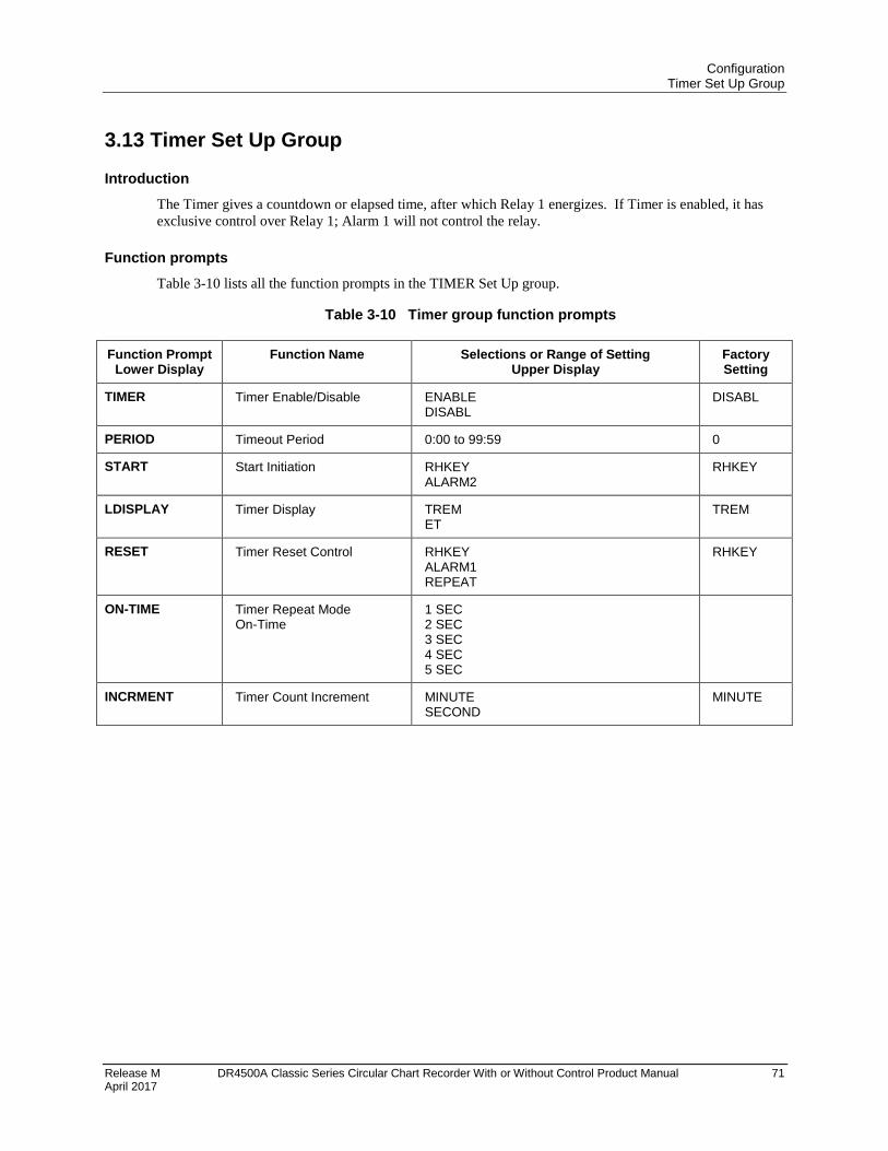
Configuration Timer Set Up Group
Release M DR4500A Classic Series Circular Chart Recorder With or Without Control Product Manual 71 April 2017
3.13 Timer Set Up Group
Introduction
The Timer gives a countdown or elapsed time, after which Relay 1 energizes. If Timer is enabled, it has
exclusive control over Relay 1; Alarm 1 will not control the relay.
Function prompts
Table 3-10 lists all the function prompts in the TIMER Set Up group.
Table 3-10 Timer group function prompts
Function Prompt Lower Display
Function Name Selections or Range of Setting Upper Display
Factory Setting
TIMER Timer Enable/Disable ENABLE DISABL
DISABL
PERIOD Timeout Period 0:00 to 99:59 0
START Start Initiation RHKEY ALARM2
RHKEY
LDISPLAY Timer Display TREM ET
TREM
RESET Timer Reset Control RHKEY ALARM1 REPEAT
RHKEY
ON-TIME Timer Repeat Mode On-Time
1 SEC 2 SEC 3 SEC 4 SEC 5 SEC
INCRMENT Timer Count Increment MINUTE SECOND
MINUTE
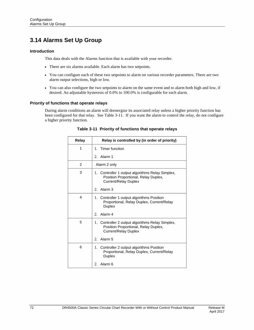
Configuration Alarms Set Up Group
72 DR4500A Classic Series Circular Chart Recorder With or Without Control Product Manual Release M April 2017
3.14 Alarms Set Up Group
Introduction
This data deals with the Alarms function that is available with your recorder.
There are six alarms available. Each alarm has two setpoints.
You can configure each of these two setpoints to alarm on various recorder parameters. There are two
alarm output selections, high or low.
You can also configure the two setpoints to alarm on the same event and to alarm both high and low, if
desired. An adjustable hysteresis of 0.0% to 100.0% is configurable for each alarm.
Priority of functions that operate relays
During alarm conditions an alarm will deenergize its associated relay unless a higher priority function has
been configured for that relay. See Table 3-11. If you want the alarm to control the relay, do not configure
a higher priority function.
Table 3-11 Priority of functions that operate relays
Relay Relay is controlled by (in order of priority)
1 1. Timer function
2. Alarm 1
2 Alarm 2 only
3 1. Controller 1 output algorithms Relay Simplex, Position Proportional, Relay Duplex, Current/Relay Duplex
2. Alarm 3
4 1. Controller 1 output algorithms Position Proportional, Relay Duplex, Current/Relay Duplex
2. Alarm 4
5 1. Controller 2 output algorithms Relay Simplex, Position Proportional, Relay Duplex, Current/Relay Duplex
2. Alarm 5
6 1. Controller 2 output algorithms Position Proportional, Relay Duplex, Current/Relay Duplex
2. Alarm 6
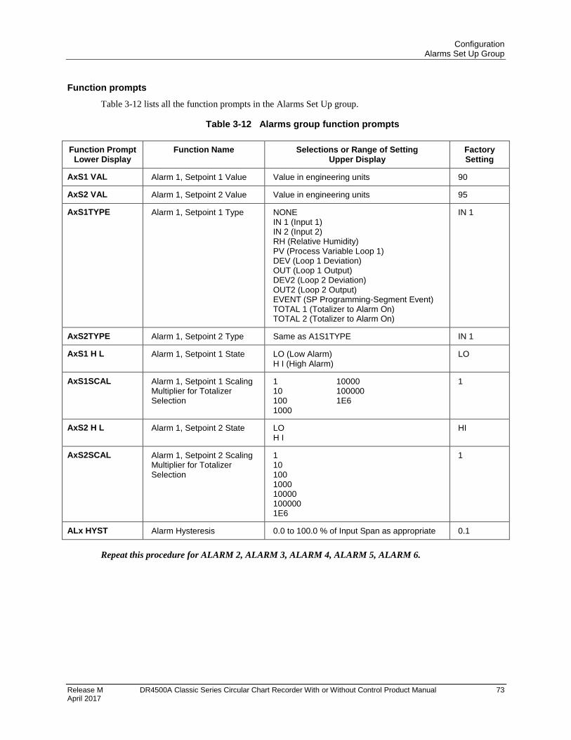
Configuration Alarms Set Up Group
Release M DR4500A Classic Series Circular Chart Recorder With or Without Control Product Manual 73 April 2017
Function prompts
Table 3-12 lists all the function prompts in the Alarms Set Up group.
Table 3-12 Alarms group function prompts
Function Prompt Lower Display
Function Name Selections or Range of Setting Upper Display
Factory Setting
AxS1 VAL Alarm 1, Setpoint 1 Value Value in engineering units 90
AxS2 VAL Alarm 1, Setpoint 2 Value Value in engineering units 95
AxS1TYPE Alarm 1, Setpoint 1 Type NONE IN 1 (Input 1) IN 2 (Input 2) RH (Relative Humidity) PV (Process Variable Loop 1) DEV (Loop 1 Deviation) OUT (Loop 1 Output) DEV2 (Loop 2 Deviation) OUT2 (Loop 2 Output) EVENT (SP Programming-Segment Event) TOTAL 1 (Totalizer to Alarm On) TOTAL 2 (Totalizer to Alarm On)
IN 1
AxS2TYPE Alarm 1, Setpoint 2 Type Same as A1S1TYPE IN 1
AxS1 H L Alarm 1, Setpoint 1 State LO (Low Alarm) H I (High Alarm)
LO
AxS1SCAL Alarm 1, Setpoint 1 Scaling Multiplier for Totalizer Selection
1 10000 10 100000 100 1E6 1000
1
AxS2 H L Alarm 1, Setpoint 2 State LO H I
HI
AxS2SCAL Alarm 1, Setpoint 2 Scaling Multiplier for Totalizer Selection
1 10 100 1000 10000 100000 1E6
1
ALx HYST Alarm Hysteresis 0.0 to 100.0 % of Input Span as appropriate 0.1
Repeat this procedure for ALARM 2, ALARM 3, ALARM 4, ALARM 5, ALARM 6.
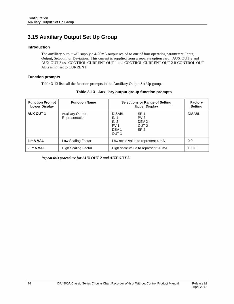
Configuration Auxiliary Output Set Up Group
74 DR4500A Classic Series Circular Chart Recorder With or Without Control Product Manual Release M April 2017
3.15 Auxiliary Output Set Up Group
Introduction
The auxiliary output will supply a 4-20mA output scaled to one of four operating parameters: Input,
Output, Setpoint, or Deviation. This current is supplied from a separate option card. AUX OUT 2 and
AUX OUT 3 use CONTROL CURRENT OUT 1 and CONTROL CURRENT OUT 2 if CONTROL OUT
ALG is not set to CURRENT.
Function prompts
Table 3-13 lists all the function prompts in the Auxiliary Output Set Up group.
Table 3-13 Auxiliary output group function prompts
Function Prompt Lower Display
Function Name Selections or Range of Setting Upper Display
Factory Setting
AUX OUT 1 Auxiliary Output Representation
DISABL SP 1 IN 1 PV 2 IN 2 DEV 2 PV 1 OUT 2 DEV 1 SP 2 OUT 1
DISABL
4 mA VAL Low Scaling Factor Low scale value to represent 4 mA 0.0
20mA VAL High Scaling Factor High scale value to represent 20 mA 100.0
Repeat this procedure for AUX OUT 2 and AUX OUT 3.
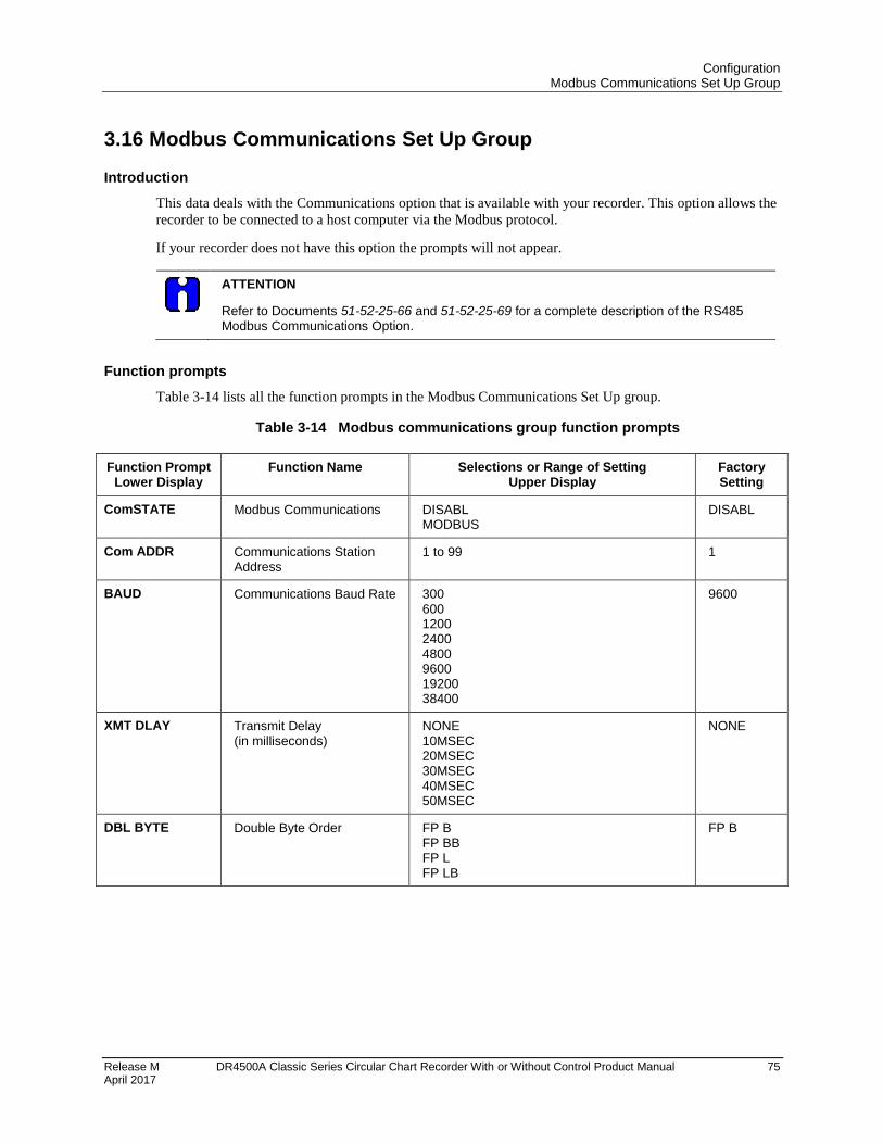
Configuration Modbus Communications Set Up Group
Release M DR4500A Classic Series Circular Chart Recorder With or Without Control Product Manual 75 April 2017
3.16 Modbus Communications Set Up Group
Introduction
This data deals with the Communications option that is available with your recorder. This option allows the
recorder to be connected to a host computer via the Modbus protocol.
If your recorder does not have this option the prompts will not appear.
ATTENTION
Refer to Documents 51-52-25-66 and 51-52-25-69 for a complete description of the RS485 Modbus Communications Option.
Function prompts
Table 3-14 lists all the function prompts in the Modbus Communications Set Up group.
Table 3-14 Modbus communications group function prompts
Function Prompt Lower Display
Function Name Selections or Range of Setting Upper Display
Factory Setting
ComSTATE Modbus Communications DISABL MODBUS
DISABL
Com ADDR Communications Station Address
1 to 99 1
BAUD Communications Baud Rate 300 600 1200 2400 4800 9600 19200 38400
9600
XMT DLAY Transmit Delay (in milliseconds)
NONE 10MSEC 20MSEC 30MSEC 40MSEC 50MSEC
NONE
DBL BYTE Double Byte Order FP B FP BB FP L FP LB
FP B
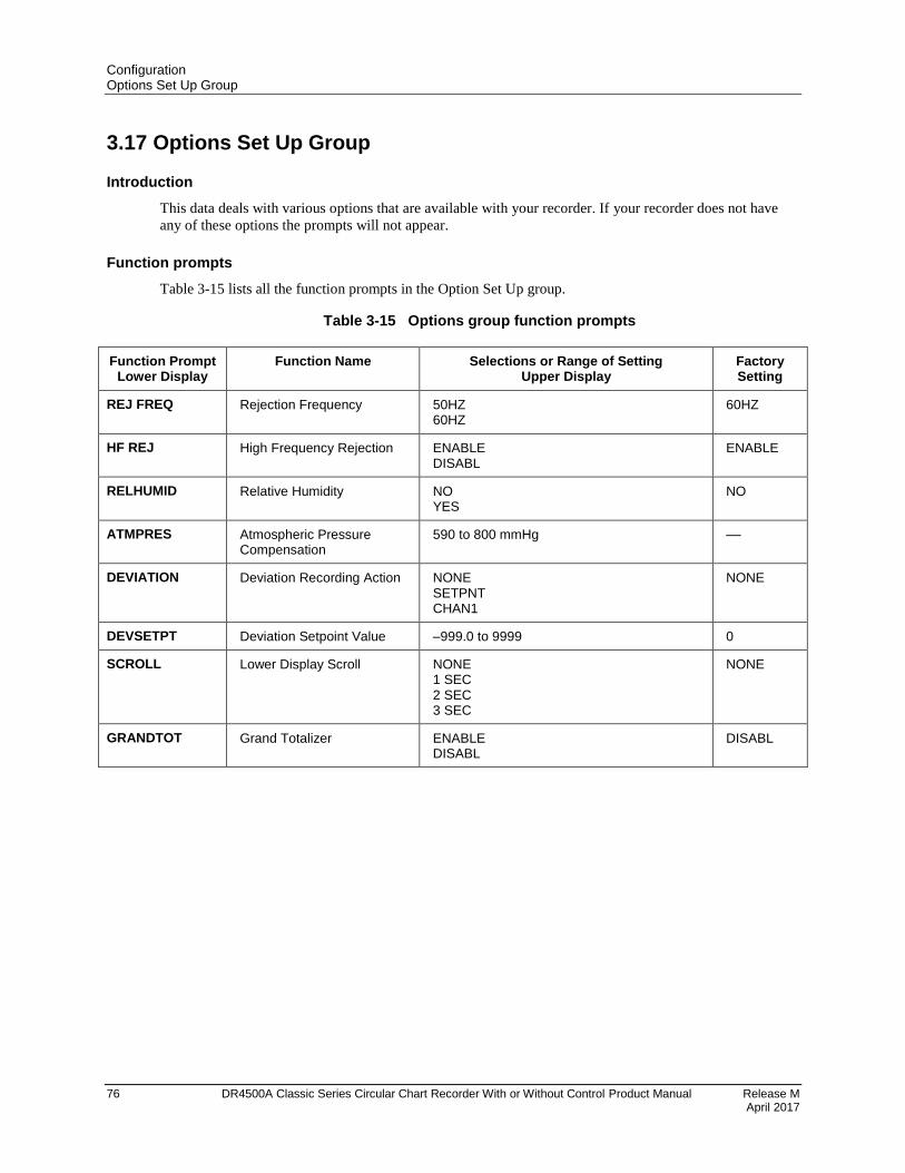
Configuration Options Set Up Group
76 DR4500A Classic Series Circular Chart Recorder With or Without Control Product Manual Release M April 2017
3.17 Options Set Up Group
Introduction
This data deals with various options that are available with your recorder. If your recorder does not have
any of these options the prompts will not appear.
Function prompts
Table 3-15 lists all the function prompts in the Option Set Up group.
Table 3-15 Options group function prompts
Function Prompt Lower Display
Function Name Selections or Range of Setting Upper Display
Factory Setting
REJ FREQ Rejection Frequency 50HZ 60HZ
60HZ
HF REJ High Frequency Rejection ENABLE DISABL
ENABLE
RELHUMID Relative Humidity NO YES
NO
ATMPRES Atmospheric Pressure Compensation
590 to 800 mmHg ––
DEVIATION Deviation Recording Action NONE SETPNT CHAN1
NONE
DEVSETPT Deviation Setpoint Value –999.0 to 9999 0
SCROLL Lower Display Scroll NONE 1 SEC 2 SEC 3 SEC
NONE
GRANDTOT Grand Totalizer ENABLE DISABL
DISABL
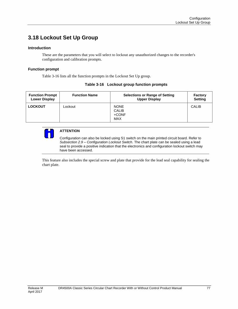
Configuration Lockout Set Up Group
Release M DR4500A Classic Series Circular Chart Recorder With or Without Control Product Manual 77 April 2017
3.18 Lockout Set Up Group
Introduction
These are the parameters that you will select to lockout any unauthorized changes to the recorder's
configuration and calibration prompts.
Function prompt
Table 3-16 lists all the function prompts in the Lockout Set Up group.
Table 3-16 Lockout group function prompts
Function Prompt Lower Display
Function Name Selections or Range of Setting Upper Display
Factory Setting
LOCKOUT Lockout NONE CALIB +CONF MAX
CALIB
ATTENTION
Configuration can also be locked using S1 switch on the main printed circuit board. Refer to Subsection 2.9 – Configuration Lockout Switch. The chart plate can be sealed using a lead
seal to provide a positive indication that the electronics and configuration lockout switch may have been accessed.
This feature also includes the special screw and plate that provide for the lead seal capability for sealing the
chart plate.
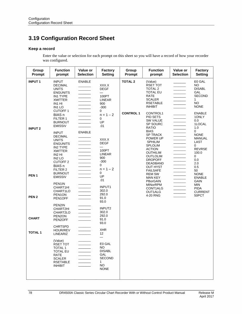
Configuration Configuration Record Sheet
78 DR4500A Classic Series Circular Chart Recorder With or Without Control Product Manual Release M April 2017
3.19 Configuration Record Sheet
Keep a record
Enter the value or selection for each prompt on this sheet so you will have a record of how your recorder
was configured.
Group Prompt
Function prompt
Value or Selection
Factory Setting
Group Prompt
Function prompt
Value or Selection
Factory Setting
INPUT 1
INPUT 2
PEN 1
PEN 2
CHART
TOTAL 1
INPUT DECIMAL UNITS ENGUNITS IN1 TYPE XMITTER IN1 HI IN1 LO CUTOFF 1
BIAS n FILTER 1 BURNOUT EMISSIV
INPUT DECIMAL UNITS ENGUNITS IN2 TYPE XMITTER IN2 HI IN2 LO CUTOFF 2
BIAS n FILTER 2 BURNOUT EMISSIV
PEN1IN CHART1HI CHART1LO PEN1ON PEN1OFF
PEN2IN CHART2HI CHART2LO PEN2ON PEN2OFF
CHRTSPD HOUR/REV LINEARIZ
(Value) RSET TOT TOTAL 1 TOTAL EU RATE SCALER RSETABLE INHIBIT
ENABLE _______ _______ _______ _______ _______ _______ _______ _______ _______ _______ _______ _______
ENABLE _______ _______ _______ _______ _______ _______ _______ _______ _______ _______ _______ _______
_______ _______ _______ _______ _______
_______ _______ _______ _______ _______
_______ _______ _______
_______ _______ _______ _______ _______ _______ _______ _______
XXX.X DEGF — 100PT LINEAR 900 -300 0
n = 1 – 2 0 UP .01
XXX.X DEGF — 100PT LINEAR 900 -300 0
n = 1 – 2 0 UP .01
INPUT1 302.0 292.0 91.0 93.0
INPUT2 302.0 292.0 91.0 93.0
XHR 12 —
E0 GAL NO DISABL GAL SECOND 1 NO NONE
TOTAL 2
CONTROL 1
(Value) RSET TOT TOTAL 2 TOTAL EU RATE SCALER RSETABLE INHIBIT
CONTROL1 PID SETS SW VALUE SP SOURC RATIO BIAS SP TRACK POWER UP SPHILIM SPLOLIM ACTION OUTHILIM OUTLOLIM DROPOFF DEADBAND OUT HYST FAILSAFE REM SW MAN KEY PBorGAIN MINorRPM CONT1ALG OUT1ALG 4-20 RNG
_______ _______ _______ _______ _______ _______ _______ _______
_______ _______ _______ _______ _______ _______ _______ _______ _______ _______ _______ _______ _______ _______ _______ _______ _______ _______ _______ _______ _______ _______ _______ _______
E0 GAL NO DISABL GAL SECOND 1 NO NONE
ENABLE 1ONLY 0.0 1LOCAL 1.0 0 NONE MANUAL LAST 0 REVRSE 100.0 0 0.0 2.0 0.5 50 NONE ENABLE GAIN MIN PIDA CURRENT 50PCT
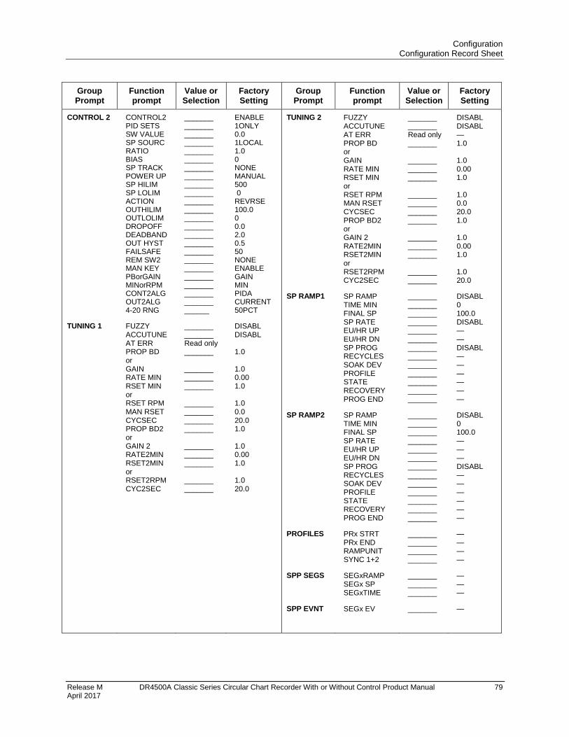
Configuration Configuration Record Sheet
Release M DR4500A Classic Series Circular Chart Recorder With or Without Control Product Manual 79 April 2017
Group Prompt
Function prompt
Value or Selection
Factory Setting
Group Prompt
Function prompt
Value or Selection
Factory Setting
CONTROL 2
TUNING 1
CONTROL2 PID SETS SW VALUE SP SOURC RATIO BIAS SP TRACK POWER UP SP HILIM SP LOLIM ACTION OUTHILIM OUTLOLIM DROPOFF DEADBAND OUT HYST FAILSAFE REM SW2 MAN KEY PBorGAIN MINorRPM CONT2ALG OUT2ALG 4-20 RNG
FUZZY ACCUTUNE AT ERR PROP BD or GAIN RATE MIN RSET MIN or RSET RPM MAN RSET CYCSEC PROP BD2 or GAIN 2 RATE2MIN RSET2MIN or RSET2RPM CYC2SEC
_______ _______ _______ _______ _______ _______ _______ _______ _______ _______ _______ _______ _______ _______ _______ _______ _______ _______ _______ _______ _______ _______ _______ ______
_______ _______ Read only _______ _______ _______ _______ _______ _______ _______ _______ _______ _______ _______ _______ _______
ENABLE 1ONLY 0.0 1LOCAL 1.0 0 NONE MANUAL 500 0 REVRSE 100.0 0 0.0 2.0 0.5 50 NONE ENABLE GAIN MIN PIDA CURRENT 50PCT
DISABL DISABL 1.0 1.0 0.00 1.0 1.0 0.0 20.0 1.0 1.0 0.00 1.0 1.0 20.0
TUNING 2
SP RAMP1
SP RAMP2
PROFILES
SPP SEGS
SPP EVNT
FUZZY ACCUTUNE AT ERR PROP BD or GAIN RATE MIN RSET MIN or RSET RPM MAN RSET CYCSEC PROP BD2 or GAIN 2 RATE2MIN RSET2MIN or RSET2RPM CYC2SEC
SP RAMP TIME MIN FINAL SP SP RATE EU/HR UP EU/HR DN SP PROG RECYCLES SOAK DEV PROFILE STATE RECOVERY PROG END
SP RAMP TIME MIN FINAL SP SP RATE EU/HR UP EU/HR DN SP PROG RECYCLES SOAK DEV PROFILE STATE RECOVERY PROG END
PRx STRT PRx END RAMPUNIT SYNC 1+2
SEGxRAMP SEGx SP SEGxTIME
SEGx EV
_______ _______ Read only _______ _______ _______ _______ _______ _______ _______ _______ _______ _______ _______ _______ _______
_______ _______ _______ _______ _______ _______ _______ _______ _______ _______ _______ _______ _______
_______ _______ _______ _______ _______ _______ _______ _______ _______ _______ _______ _______ _______
_______ _______ _______ _______
_______ _______ _______
_______
DISABL DISABL — 1.0 1.0 0.00 1.0 1.0 0.0 20.0 1.0 1.0 0.00 1.0 1.0 20.0
DISABL 0 100.0 DISABL — — DISABL — — — — — —
DISABL 0 100.0 — — — DISABL — — — — — —
— — — —
— — —
—
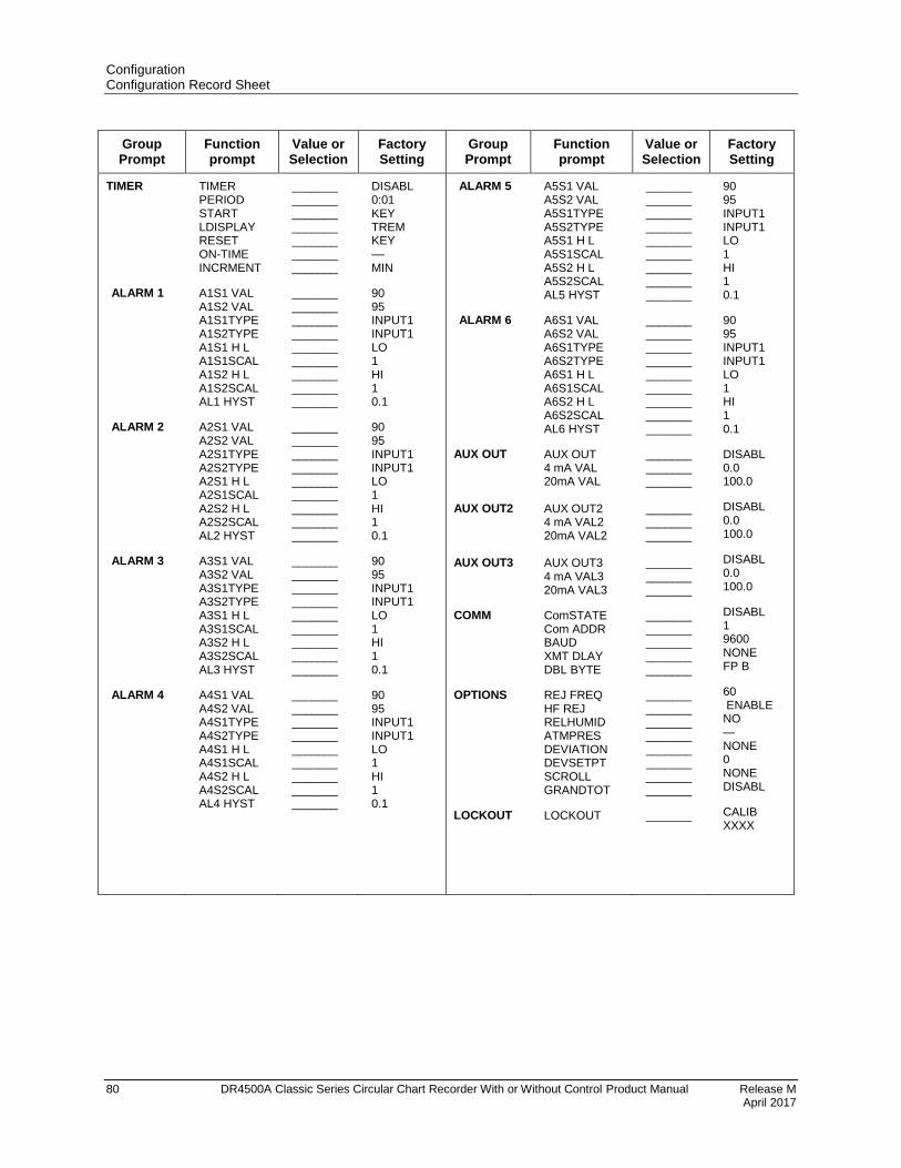
Configuration Configuration Record Sheet
80 DR4500A Classic Series Circular Chart Recorder With or Without Control Product Manual Release M April 2017
Group Prompt
Function prompt
Value or Selection
Factory Setting
Group Prompt
Function prompt
Value or Selection
Factory Setting
TIMER
ALARM 1
ALARM 2
ALARM 3
ALARM 4
TIMER PERIOD START LDISPLAY RESET ON-TIME INCRMENT
A1S1 VAL A1S2 VAL A1S1TYPE A1S2TYPE A1S1 H L A1S1SCAL A1S2 H L A1S2SCAL AL1 HYST
A2S1 VAL A2S2 VAL A2S1TYPE A2S2TYPE A2S1 H L A2S1SCAL A2S2 H L A2S2SCAL AL2 HYST
A3S1 VAL A3S2 VAL A3S1TYPE A3S2TYPE A3S1 H L A3S1SCAL A3S2 H L A3S2SCAL AL3 HYST
A4S1 VAL A4S2 VAL A4S1TYPE A4S2TYPE A4S1 H L A4S1SCAL A4S2 H L A4S2SCAL AL4 HYST
_______ _______ _______ _______ _______ _______ _______
_______ _______ _______ _______ _______ _______ _______ _______ _______
_______ _______ _______ _______ _______ _______ _______ _______ _______
_______ _______ _______ _______ _______ _______ _______ _______ _______
_______ _______ _______ _______ _______ _______ _______ _______ _______
DISABL 0:01 KEY TREM KEY –– MIN
90 95 INPUT1 INPUT1 LO 1 HI 1 0.1
90 95 INPUT1 INPUT1 LO 1 HI 1 0.1
90 95 INPUT1 INPUT1 LO 1 HI 1 0.1
90 95 INPUT1 INPUT1 LO 1 HI 1 0.1
ALARM 5
ALARM 6
AUX OUT AUX OUT2 AUX OUT3
COMM
OPTIONS
LOCKOUT
A5S1 VAL A5S2 VAL A5S1TYPE A5S2TYPE A5S1 H L A5S1SCAL A5S2 H L A5S2SCAL AL5 HYST
A6S1 VAL A6S2 VAL A6S1TYPE A6S2TYPE A6S1 H L A6S1SCAL A6S2 H L A6S2SCAL AL6 HYST
AUX OUT 4 mA VAL 20mA VAL AUX OUT2 4 mA VAL2 20mA VAL2 AUX OUT3 4 mA VAL3 20mA VAL3
ComSTATE Com ADDR BAUD XMT DLAY DBL BYTE
REJ FREQ HF REJ RELHUMID ATMPRES DEVIATION DEVSETPT SCROLL GRANDTOT
LOCKOUT
_______ _______ _______ _______ _______ _______ _______ _______ _______
_______ _______ _______ _______ _______ _______ _______ _______ _______
_______ _______ _______ _______ _______ _______ _______ _______ _______
_______ _______ _______ _______ _______
_______ _______ _______ _______ _______ _______ _______ _______
_______
90 95 INPUT1 INPUT1 LO 1 HI 1 0.1
90 95 INPUT1 INPUT1 LO 1 HI 1 0.1
DISABL 0.0 100.0
DISABL 0.0 100.0
DISABL 0.0 100.0
DISABL 1 9600 NONE FP B
60 ENABLE NO — NONE 0 NONE DISABL
CALIB XXXX
Configuration Parameter Definitions Overview
Release M DR4500A Classic Series Circular Chart Recorder With or Without Control Product Manual 81 April 2017
4. Configuration Parameter Definitions
4.1 Overview
Introduction
This section provides information for all the user-configurable control parameters listed in the
configuration section. If you aren't familiar with these parameters, this section gives you the parameter
prompt, the selection or range of setting that you can make, and a definition of how each parameter setting
affects recorder performance. It will also refer you to any other prompts that might be affected by your
selection.
Parameter groups and prompts
The control information is found in three configuration groups which are accessed by the SET UP key.
Each of these groups contains prompts, viewed in the lower display, which deal with functions that are
pertinent to that particular group. These are accessed by pressing the FUNC key.
The selections or values are listed in the upper display. Refer to Section 3 - Configuration for step by
step instructions.
What’s in this section?
The table below lists the topics that are covered in this section. They are listed in the order of their
appearance in the recorder.
Topic See Page
4.1 Overview 81
4.2 Input Parameters Set Up Group 82
4.3 Pen Parameters Set Up Group 86
4.4 Chart Parameters Set Up Group 88
4.5 Total Parameters Set Up Group 89
4.6 Control Parameters Set Up Group 91
4.7 Tuning Parameters Set Up Group 100
4.8 Setpoint Ramp Set Up Group 103
4.9 Timer Set Up Group 105
4.10 Alarms Set Up Group 106
4.11 Auxiliary Output Set Up Group 109
4.12 Modbus Communications Set Up Group 111
4.13 Options Set Up Group 112
4.14 Lockout Parameters Set Up Group 114
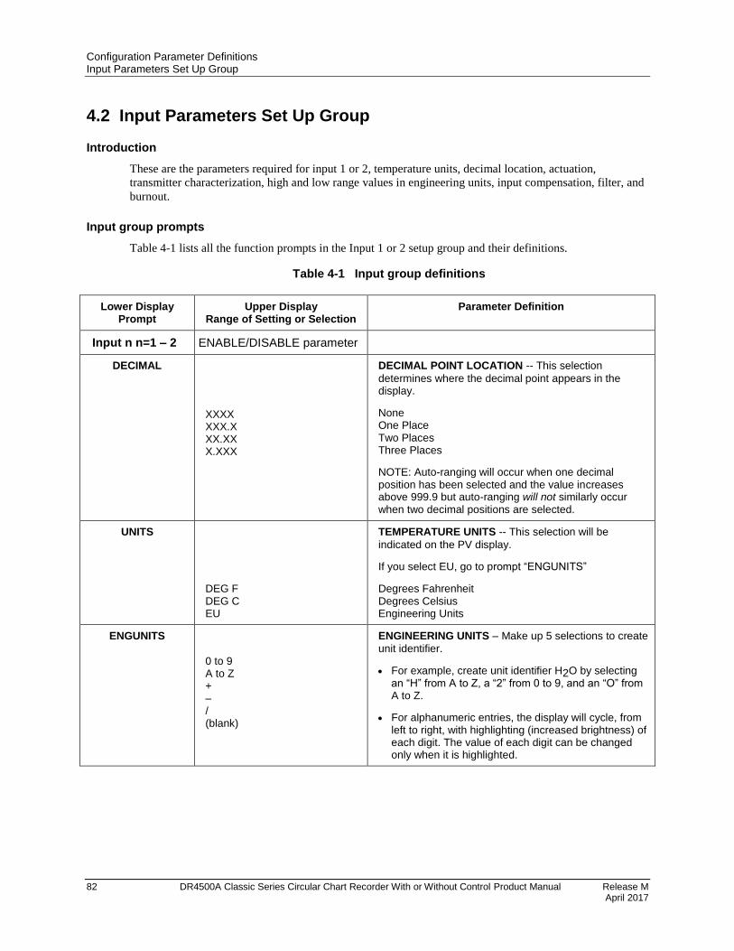
Configuration Parameter Definitions Input Parameters Set Up Group
82 DR4500A Classic Series Circular Chart Recorder With or Without Control Product Manual Release M April 2017
4.2 Input Parameters Set Up Group
Introduction
These are the parameters required for input 1 or 2, temperature units, decimal location, actuation,
transmitter characterization, high and low range values in engineering units, input compensation, filter, and
burnout.
Input group prompts
Table 4-1 lists all the function prompts in the Input 1 or 2 setup group and their definitions.
Table 4-1 Input group definitions
Lower Display Prompt
Upper Display Range of Setting or Selection
Parameter Definition
Input n n=1 – 2 ENABLE/DISABLE parameter
DECIMAL
XXXX XXX.X XX.XX X.XXX
DECIMAL POINT LOCATION -- This selection
determines where the decimal point appears in the display.
None One Place Two Places Three Places
NOTE: Auto-ranging will occur when one decimal position has been selected and the value increases above 999.9 but auto-ranging will not similarly occur when two decimal positions are selected.
UNITS
DEG F DEG C EU
TEMPERATURE UNITS -- This selection will be
indicated on the PV display.
If you select EU, go to prompt “ENGUNITS”
Degrees Fahrenheit Degrees Celsius Engineering Units
ENGUNITS 0 to 9 A to Z + – / (blank)
ENGINEERING UNITS – Make up 5 selections to create
unit identifier.
For example, create unit identifier H2O by selecting an “H” from A to Z, a “2” from 0 to 9, and an “O” from A to Z.
For alphanumeric entries, the display will cycle, from left to right, with highlighting (increased brightness) of each digit. The value of each digit can be changed only when it is highlighted.
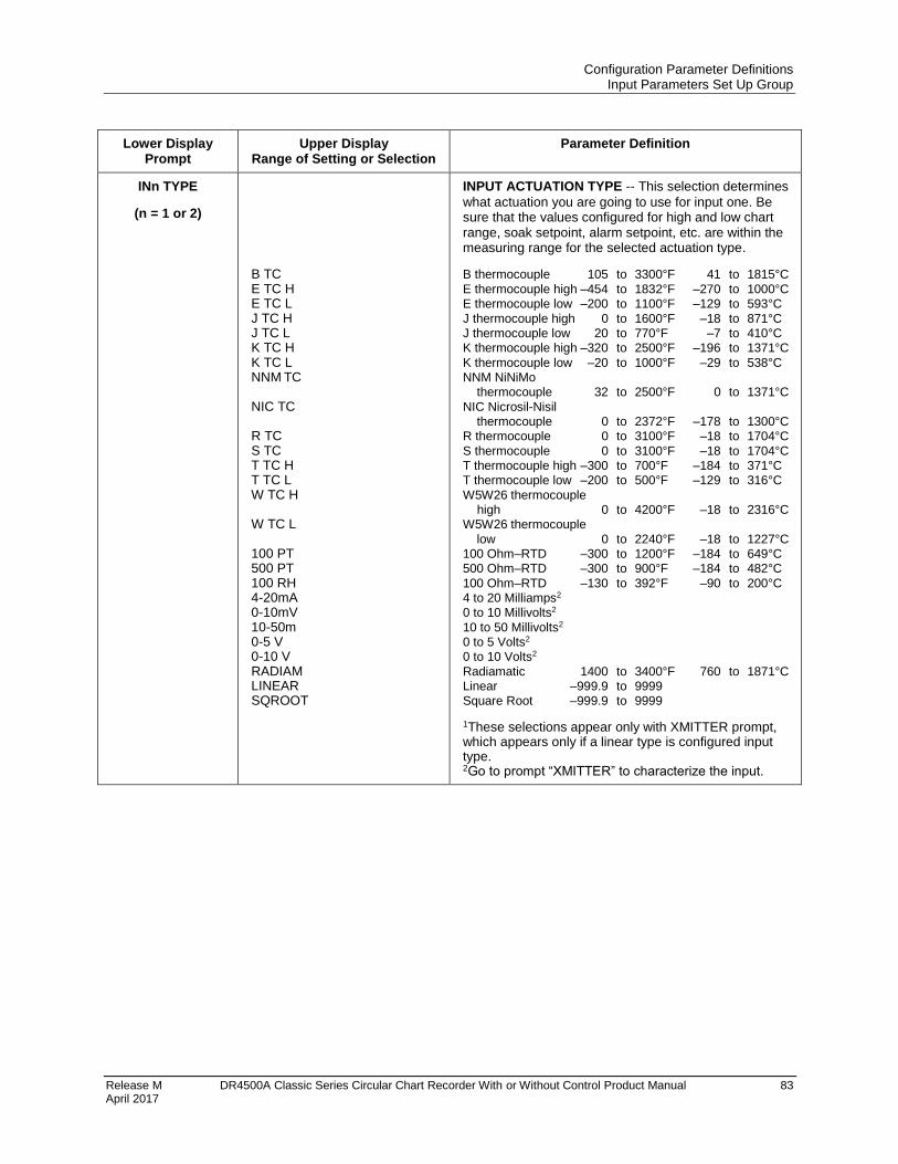
Configuration Parameter Definitions Input Parameters Set Up Group
Release M DR4500A Classic Series Circular Chart Recorder With or Without Control Product Manual 83 April 2017
Lower Display Prompt
Upper Display Range of Setting or Selection
Parameter Definition
INn TYPE
(n = 1 or 2)
B TC E TC H E TC L J TC H J TC L K TC H K TC L NNM TC NIC TC R TC S TC T TC H T TC L W TC H W TC L 100 PT 500 PT 100 RH 4-20mA 0-10mV 10-50m 0-5 V 0-10 V
RADIAM LINEAR SQROOT
INPUT ACTUATION TYPE -- This selection determines
what actuation you are going to use for input one. Be sure that the values configured for high and low chart range, soak setpoint, alarm setpoint, etc. are within the measuring range for the selected actuation type.
B thermocouple 105 to 3300°F 41 to 1815°C
E thermocouple high –454 to 1832°F –270 to 1000°C E thermocouple low –200 to 1100°F –129 to 593°C
J thermocouple high 0 to 1600°F –18 to 871°C J thermocouple low 20 to 770°F –7 to 410°C K thermocouple high –320 to 2500°F –196 to 1371°C
K thermocouple low –20 to 1000°F –29 to 538°C NNM NiNiMo thermocouple 32 to 2500°F 0 to 1371°C
NIC Nicrosil-Nisil thermocouple 0 to 2372°F –178 to 1300°C R thermocouple 0 to 3100°F –18 to 1704°C
S thermocouple 0 to 3100°F –18 to 1704°C T thermocouple high –300 to 700°F –184 to 371°C T thermocouple low –200 to 500°F –129 to 316°C
W5W26 thermocouple high 0 to 4200°F –18 to 2316°C W5W26 thermocouple
low 0 to 2240°F –18 to 1227°C 100 Ohm–RTD –300 to 1200°F –184 to 649°C 500 Ohm–RTD –300 to 900°F –184 to 482°C
100 Ohm–RTD –130 to 392°F –90 to 200°C 4 to 20 Milliamps2 0 to 10 Millivolts2
10 to 50 Millivolts2 0 to 5 Volts2 0 to 10 Volts2
Radiamatic 1400 to 3400°F 760 to 1871°C Linear –999.9 to 9999 Square Root –999.9 to 9999
1These selections appear only with XMITTER prompt, which appears only if a linear type is configured input type. 2Go to prompt “XMITTER” to characterize the input.

Configuration Parameter Definitions Input Parameters Set Up Group
84 DR4500A Classic Series Circular Chart Recorder With or Without Control Product Manual Release M April 2017
Lower Display Prompt
Upper Display Range of Setting or Selection
Parameter Definition
XMITTER
B TC E TC H E TC L J TC H J TC L K TC H K TC L NNM H NIC TC R TC S TC T TC H T TC L W TC H W TC L 100 PT 500 PT 100 RH LINEAR SQROOT
TRANSMITTER CHARACTERIZATION — This
selection lets you instruct the recorder to characterize a linear input to represent a nonlinear one.
NOTE: Prompt only appears when a linear actuation is selected at prompt ‘IN1 TYPE”.
FOR EXAMPLE: If input 1 is a 4 to 20 mA signal, but the signal represents a type "K" thermocouple; select "K TC H" and the recorder will characterize the 4 to 20 mA signal so that it is treated as a type "K" thermocouple input (high range).
B Type Thermocouple E Type Thermocouple High E Type Thermocouple Low J Type Thermocouple High J Type Thermocouple Low K Type Thermocouple High K Type Thermocouple Low NNM NiNiMo Type Thermocouple High NIC Nicrosil Nisil Thermocouple R Type Thermocouple S Type Thermocouple T Type Thermocouple High T Type Thermocouple Low W5W26 Type Thermocouple High W5W26 Type Thermocouple Low 100 Ohm–RTD 500 Ohm–RTD 100 Ohm –RTD Linear Range Extracts Square Root
INn HI
(n = 1 or 2)
–999.9 to 9999.
or
–999 to 9999 in engineering units
INPUT HIGH RANGE VALUE in engineering units is
displayed for all inputs but can only be configured for linear or square root transmitter characterization. Otherwise, this is a read-only display of the higher range value for the selected T/C or RTD input including transmitter characterization, if applicable.
Scale the #1 input signal to the display value you want for 100%.
EXAMPLE:
Actuation (Input) = 4 to 20 mA Process Variable = Flow Range of Flow = 0 to 250 Gal/Min High Range display value = 250 Then 20 mA = 250 Gal/Min
The control setpoint will be limited by the range of units selected here.
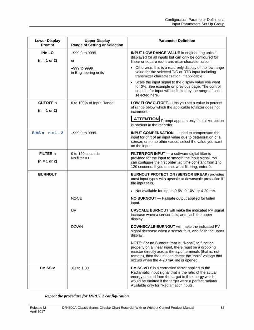
Configuration Parameter Definitions Input Parameters Set Up Group
Release M DR4500A Classic Series Circular Chart Recorder With or Without Control Product Manual 85 April 2017
Lower Display Prompt
Upper Display Range of Setting or Selection
Parameter Definition
INn LO
(n = 1 or 2)
–999.9 to 9999.
or
–999 to 9999 in Engineering units
INPUT LOW RANGE VALUE in engineering units is
displayed for all inputs but can only be configured for linear or square root transmitter characterization.
Otherwise, this is a read-only display of the low range value for the selected T/C or RTD input including transmitter characterization, if applicable.
Scale the input signal to the display value you want for 0%. See example on previous page. The control setpoint for Input will be limited by the range of units selected here.
CUTOFF n
(n = 1 or 2)
0 to 100% of Input Range LOW FLOW CUTOFF—Lets you set a value in percent
of range below which the applicable totalizer does not increment.
ATTENTION Prompt appears only if totalizer option is present in the recorder.
BIAS n n = 1 – 2 –999.9 to 9999. INPUT COMPENSATION — used to compensate the
input for drift of an input value due to deterioration of a sensor, or some other cause; select the value you want on the input.
FILTER n
(n = 1 or 2)
0 to 120 seconds No filter = 0
FILTER FOR INPUT — a software digital filter is
provided for the input to smooth the input signal. You can configure the first order lag time constant from 1 to 120 seconds. If you do not want filtering, enter 0.
BURNOUT
NONE
UP
DOWN
BURNOUT PROTECTION (SENSOR BREAK) provides
most input types with upscale or downscale protection if the input fails.
Not available for inputs 0-5V, 0-10V, or 4-20 mA.
NO BURNOUT — Failsafe output applied for failed
input.
UPSCALE BURNOUT will make the indicated PV signal
increase when a sensor fails, and flash the upper display.
DOWNSCALE BURNOUT will make the indicated PV
signal decrease when a sensor fails, and flash the upper display.
NOTE: For no Burnout (that is, “None”) to function properly on a linear input, there must be a dropping resistor directly across the input terminals (that is, not
remote), then the unit can detect the “zero” voltage that occurs when the 4-20 mA line is opened.
EMISSIV .01 to 1.00 EMISSIVITY is a correction factor applied to the
Radiamatic input signal that is the ratio of the actual energy emitted from the target to the energy which would be emitted if the target were a perfect radiator. Available only for “Radiamatic” inputs.
Repeat the procedure for INPUT 2 configuration.
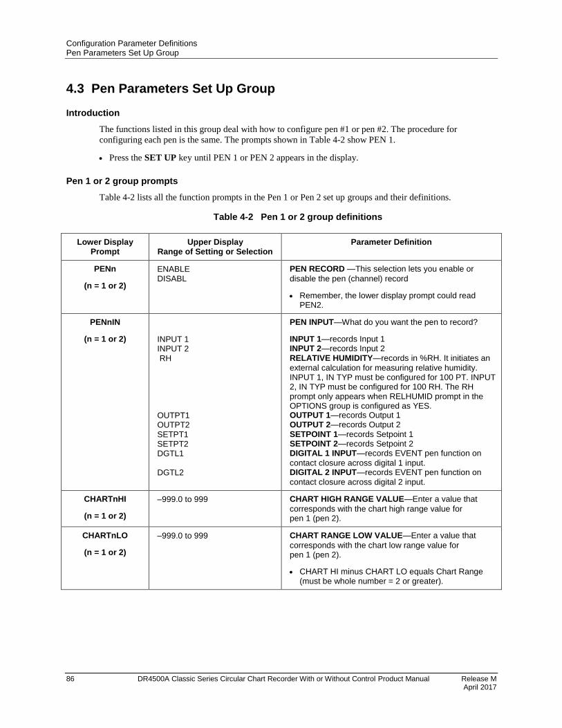
Configuration Parameter Definitions Pen Parameters Set Up Group
86 DR4500A Classic Series Circular Chart Recorder With or Without Control Product Manual Release M April 2017
4.3 Pen Parameters Set Up Group
Introduction
The functions listed in this group deal with how to configure pen #1 or pen #2. The procedure for
configuring each pen is the same. The prompts shown in Table 4-2 show PEN 1.
Press the SET UP key until PEN 1 or PEN 2 appears in the display.
Pen 1 or 2 group prompts
Table 4-2 lists all the function prompts in the Pen 1 or Pen 2 set up groups and their definitions.
Table 4-2 Pen 1 or 2 group definitions
Lower Display Prompt
Upper Display Range of Setting or Selection
Parameter Definition
PENn
(n = 1 or 2)
ENABLE DISABL
PEN RECORD —This selection lets you enable or
disable the pen (channel) record
Remember, the lower display prompt could read PEN2.
PENnIN
(n = 1 or 2)
INPUT 1 INPUT 2 RH OUTPT1 OUTPT2 SETPT1 SETPT2 DGTL1 DGTL2
PEN INPUT—What do you want the pen to record?
INPUT 1—records Input 1 INPUT 2—records Input 2 RELATIVE HUMIDITY—records in %RH. It initiates an
external calculation for measuring relative humidity. INPUT 1, IN TYP must be configured for 100 PT. INPUT 2, IN TYP must be configured for 100 RH. The RH prompt only appears when RELHUMID prompt in the OPTIONS group is configured as YES. OUTPUT 1—records Output 1 OUTPUT 2—records Output 2 SETPOINT 1—records Setpoint 1 SETPOINT 2—records Setpoint 2 DIGITAL 1 INPUT—records EVENT pen function on
contact closure across digital 1 input. DIGITAL 2 INPUT—records EVENT pen function on
contact closure across digital 2 input.
CHARTnHI
(n = 1 or 2)
–999.0 to 999 CHART HIGH RANGE VALUE—Enter a value that
corresponds with the chart high range value for pen 1 (pen 2).
CHARTnLO
(n = 1 or 2)
–999.0 to 999 CHART RANGE LOW VALUE—Enter a value that
corresponds with the chart low range value for pen 1 (pen 2).
CHART HI minus CHART LO equals Chart Range (must be whole number = 2 or greater).
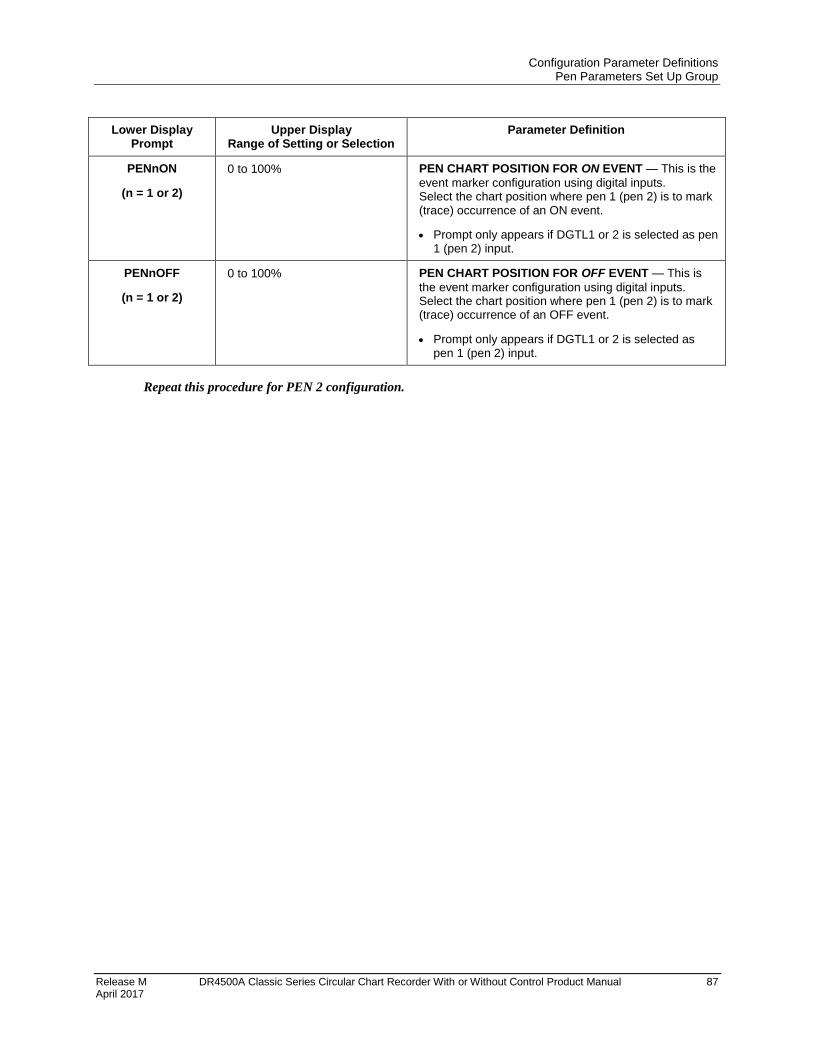
Configuration Parameter Definitions Pen Parameters Set Up Group
Release M DR4500A Classic Series Circular Chart Recorder With or Without Control Product Manual 87 April 2017
Lower Display Prompt
Upper Display Range of Setting or Selection
Parameter Definition
PENnON
(n = 1 or 2)
0 to 100% PEN CHART POSITION FOR ON EVENT — This is the
event marker configuration using digital inputs. Select the chart position where pen 1 (pen 2) is to mark (trace) occurrence of an ON event.
Prompt only appears if DGTL1 or 2 is selected as pen 1 (pen 2) input.
PENnOFF
(n = 1 or 2)
0 to 100% PEN CHART POSITION FOR OFF EVENT — This is
the event marker configuration using digital inputs. Select the chart position where pen 1 (pen 2) is to mark (trace) occurrence of an OFF event.
Prompt only appears if DGTL1 or 2 is selected as pen 1 (pen 2) input.
Repeat this procedure for PEN 2 configuration.
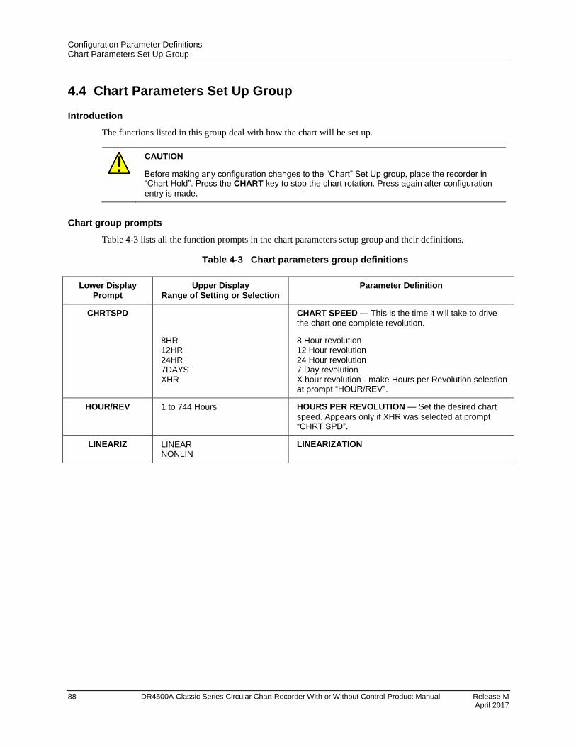
Configuration Parameter Definitions Chart Parameters Set Up Group
88 DR4500A Classic Series Circular Chart Recorder With or Without Control Product Manual Release M April 2017
4.4 Chart Parameters Set Up Group
Introduction
The functions listed in this group deal with how the chart will be set up.
CAUTION
Before making any configuration changes to the “Chart” Set Up group, place the recorder in “Chart Hold”. Press the CHART key to stop the chart rotation. Press again after configuration
entry is made.
Chart group prompts
Table 4-3 lists all the function prompts in the chart parameters setup group and their definitions.
Table 4-3 Chart parameters group definitions
Lower Display Prompt
Upper Display Range of Setting or Selection
Parameter Definition
CHRTSPD
8HR 12HR 24HR 7DAYS XHR
CHART SPEED — This is the time it will take to drive
the chart one complete revolution.
8 Hour revolution 12 Hour revolution 24 Hour revolution 7 Day revolution X hour revolution - make Hours per Revolution selection at prompt “HOUR/REV”.
HOUR/REV 1 to 744 Hours HOURS PER REVOLUTION — Set the desired chart
speed. Appears only if XHR was selected at prompt “CHRT SPD”.
LINEARIZ LINEAR NONLIN
LINEARIZATION
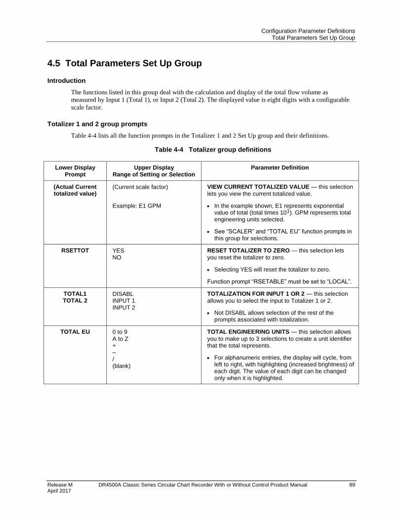
Configuration Parameter Definitions Total Parameters Set Up Group
Release M DR4500A Classic Series Circular Chart Recorder With or Without Control Product Manual 89 April 2017
4.5 Total Parameters Set Up Group
Introduction
The functions listed in this group deal with the calculation and display of the total flow volume as
measured by Input 1 (Total 1), or Input 2 (Total 2). The displayed value is eight digits with a configurable
scale factor.
Totalizer 1 and 2 group prompts
Table 4-4 lists all the function prompts in the Totalizer 1 and 2 Set Up group and their definitions.
Table 4-4 Totalizer group definitions
Lower Display Prompt
Upper Display Range of Setting or Selection
Parameter Definition
(Actual Current totalized value)
(Current scale factor)
Example: E1 GPM
VIEW CURRENT TOTALIZED VALUE — this selection
lets you view the current totalized value.
In the example shown, E1 represents exponential value of total (total times 101). GPM represents total engineering units selected.
See “SCALER” and “TOTAL EU” function prompts in this group for selections.
RSETTOT YES NO
RESET TOTALIZER TO ZERO — this selection lets
you reset the totalizer to zero.
Selecting YES will reset the totalizer to zero.
Function prompt “RSETABLE” must be set to “LOCAL”.
TOTAL1 TOTAL 2
DISABL INPUT 1 INPUT 2
TOTALIZATION FOR INPUT 1 OR 2 — this selection
allows you to select the input to Totalizer 1 or 2.
Not DISABL allows selection of the rest of the prompts associated with totalization.
TOTAL EU 0 to 9 A to Z + – / (blank)
TOTAL ENGINEERING UNITS — this selection allows
you to make up to 3 selections to create a unit identifier that the total represents.
For alphanumeric entries, the display will cycle, from left to right, with highlighting (increased brightness) of each digit. The value of each digit can be changed only when it is highlighted.

Configuration Parameter Definitions Total Parameters Set Up Group
90 DR4500A Classic Series Circular Chart Recorder With or Without Control Product Manual Release M April 2017
Lower Display Prompt
Upper Display Range of Setting or Selection
Parameter Definition
RATE
SECOND MINUTE HOUR DAY M/DAY
RATE OF INTEGRATION — This selection allows you
to select the desired rate of integration. It must match scaling of input units:
EXAMPLE:
GPM must use “MINUTE” PPH must use “HOUR”
SECOND - EU (Engineering Units) per second. MINUTE - EU per minute HOUR - EU per hour DAY - EU per day M/DAY - Millions of Units per day (multiplier) 106 x input
SCALER 1 10 100 1000 10000 100000 1E6
TOTALIZER SCALE FACTOR — this selection allows
you to select a scale factor (that is, a Multiplier) for the totalizer display. It affects only the display.
The desired factor is applied to the calculated value to extend the maximum flow range that can be displayed.
Scaler selection does not affect the totalization value printed on the chart.
EXAMPLE:
1E6 equals 1 times 106 (1,000,000)
RSETABLE NO LOCAL EXT SW1 EXT SW2
LOCAL TOTALIZER RESET— Allows the totalizer
value to be reset to zero via the display/keypad. EXTERNAL SWITCH 1—Allows the totalizer to be set
to zero upon switch #1 closure. (Digital Input #1) EXTERNAL SWITCH 2—Allows the totalizer to be set
to zero upon switch #2 closure. (Digital Input #2)
INHIBIT
NONE S1 OPEN S1 CLOSE S2 OPEN S2 CLOSE
The totalizer will be inhibited while the configured action is true.
External SW1 open inhibits totalizer. External SW1 closed inhibits totalizer. External SW2 open inhibits totalizer. External SW2 closed inhibits totalizer.
Repeat the configuration for TOTAL 2.

Configuration Parameter Definitions Control Parameters Set Up Group
Release M DR4500A Classic Series Circular Chart Recorder With or Without Control Product Manual 91 April 2017
4.6 Control Parameters Set Up Group
Introduction
The functions listed in this group deal with how the DR4500A will control the process including: number
of tuning parameter sets, setpoint source, ratio, bias, tracking, power-up recall, setpoint limits, output
direction and limits, deadband and hysteresis, control algorithm, output algorithm, and the current duplex
range. There are two control groups.
Control group prompts
Table 4-5 lists all the function prompts in the Control 1 or Control 2 set up groups and their definitions.
Table 4-5 Control 1 or 2 group definitions
Lower Display Prompt
Upper Display Range of Setting or Selection
Parameter Definition
CONTROL 1 ENABLE DISABL
CONTROL 1 — allows you to enable or disable control
loop #1.
PID SETS NUMBER OF TUNING PARAMETER SETS — this
selection lets you choose one or two sets of tuning constants (gain, rate, and reset).
1 ONLY ONE SET ONLY — only one set of tuning parameters is
available. Configure the values for: Gain (proportional band) Rate Reset Time Cycle Time (if time proportional is used)
2KEYBD TWO SETS KEYBOARD SELECTABLE — two sets of
tuning parameters can be configured and can be selected at the operator interface.
Press LOWR DISP key until you see "PID SET1" or
“PID SET2” to switch between sets. Configure the values for: Gain, Rate , Reset, Cycle Time Gain #2, Rate #2, Reset #2, Cycle #2 Time
2PV SW TWO SETS PV AUTOMATIC SWITCHOVER — when
the process variable is GREATER than the value set at prompt "SW VALUE" (Switchover Value), the recorder will use Gain, Rate, Reset, and Cycle Time. The active PID SET can be read in the lower display.
When the process variable is LESS than the value
set at prompt "SW VALUE," the recorder will use Gain #2, Rate #2, Reset #2, and Cycle #2 Time. The active PID SET can be read in the lower display.
Other prompts affected: SW VALUE
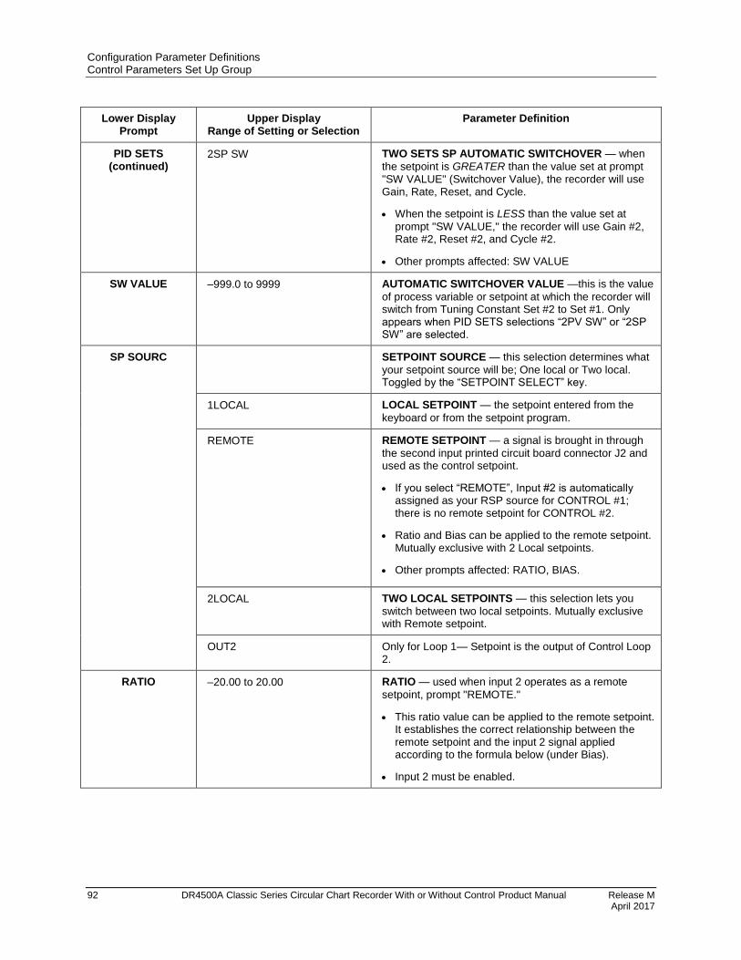
Configuration Parameter Definitions Control Parameters Set Up Group
92 DR4500A Classic Series Circular Chart Recorder With or Without Control Product Manual Release M April 2017
Lower Display Prompt
Upper Display Range of Setting or Selection
Parameter Definition
PID SETS (continued)
2SP SW TWO SETS SP AUTOMATIC SWITCHOVER — when
the setpoint is GREATER than the value set at prompt "SW VALUE" (Switchover Value), the recorder will use Gain, Rate, Reset, and Cycle.
When the setpoint is LESS than the value set at
prompt "SW VALUE," the recorder will use Gain #2, Rate #2, Reset #2, and Cycle #2.
Other prompts affected: SW VALUE
SW VALUE –999.0 to 9999 AUTOMATIC SWITCHOVER VALUE —this is the value
of process variable or setpoint at which the recorder will switch from Tuning Constant Set #2 to Set #1. Only appears when PID SETS selections “2PV SW” or “2SP SW” are selected.
SP SOURC SETPOINT SOURCE — this selection determines what
your setpoint source will be; One local or Two local. Toggled by the “SETPOINT SELECT” key.
1LOCAL LOCAL SETPOINT — the setpoint entered from the
keyboard or from the setpoint program.
REMOTE
REMOTE SETPOINT — a signal is brought in through
the second input printed circuit board connector J2 and used as the control setpoint.
If you select “REMOTE”, Input #2 is automatically assigned as your RSP source for CONTROL #1; there is no remote setpoint for CONTROL #2.
Ratio and Bias can be applied to the remote setpoint. Mutually exclusive with 2 Local setpoints.
Other prompts affected: RATIO, BIAS.
2LOCAL TWO LOCAL SETPOINTS — this selection lets you
switch between two local setpoints. Mutually exclusive with Remote setpoint.
OUT2 Only for Loop 1— Setpoint is the output of Control Loop 2.
RATIO –20.00 to 20.00 RATIO — used when input 2 operates as a remote
setpoint, prompt "REMOTE."
This ratio value can be applied to the remote setpoint. It establishes the correct relationship between the remote setpoint and the input 2 signal applied according to the formula below (under Bias).
Input 2 must be enabled.
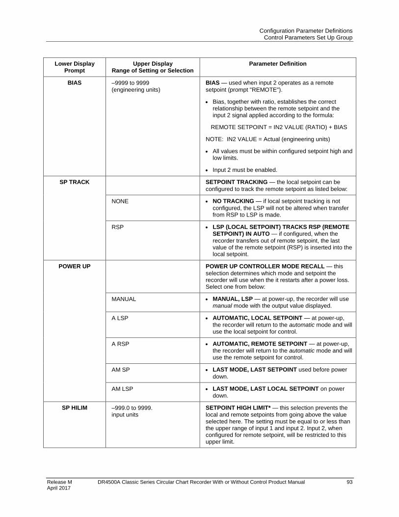
Configuration Parameter Definitions Control Parameters Set Up Group
Release M DR4500A Classic Series Circular Chart Recorder With or Without Control Product Manual 93 April 2017
Lower Display Prompt
Upper Display Range of Setting or Selection
Parameter Definition
BIAS –9999 to 9999 (engineering units)
BIAS — used when input 2 operates as a remote
setpoint (prompt "REMOTE").
Bias, together with ratio, establishes the correct relationship between the remote setpoint and the input 2 signal applied according to the formula:
REMOTE SETPOINT = IN2 VALUE (RATIO) + BIAS
NOTE: IN2 VALUE = Actual (engineering units)
All values must be within configured setpoint high and low limits.
Input 2 must be enabled.
SP TRACK SETPOINT TRACKING — the local setpoint can be
configured to track the remote setpoint as listed below:
NONE NO TRACKING — if local setpoint tracking is not
configured, the LSP will not be altered when transfer from RSP to LSP is made.
RSP LSP (LOCAL SETPOINT) TRACKS RSP (REMOTE SETPOINT) IN AUTO — if configured, when the
recorder transfers out of remote setpoint, the last value of the remote setpoint (RSP) is inserted into the local setpoint.
POWER UP POWER UP CONTROLLER MODE RECALL — this
selection determines which mode and setpoint the recorder will use when the it restarts after a power loss. Select one from below:
MANUAL MANUAL, LSP — at power-up, the recorder will use manual mode with the output value displayed.
A LSP AUTOMATIC, LOCAL SETPOINT — at power-up,
the recorder will return to the automatic mode and will use the local setpoint for control.
A RSP AUTOMATIC, REMOTE SETPOINT — at power-up, the recorder will return to the automatic mode and will use the remote setpoint for control.
AM SP LAST MODE, LAST SETPOINT used before power
down.
AM LSP LAST MODE, LAST LOCAL SETPOINT on power
down.
SP HILIM –999.0 to 9999. input units
SETPOINT HIGH LIMIT* — this selection prevents the
local and remote setpoints from going above the value selected here. The setting must be equal to or less than the upper range of input 1 and input 2. Input 2, when configured for remote setpoint, will be restricted to this upper limit.
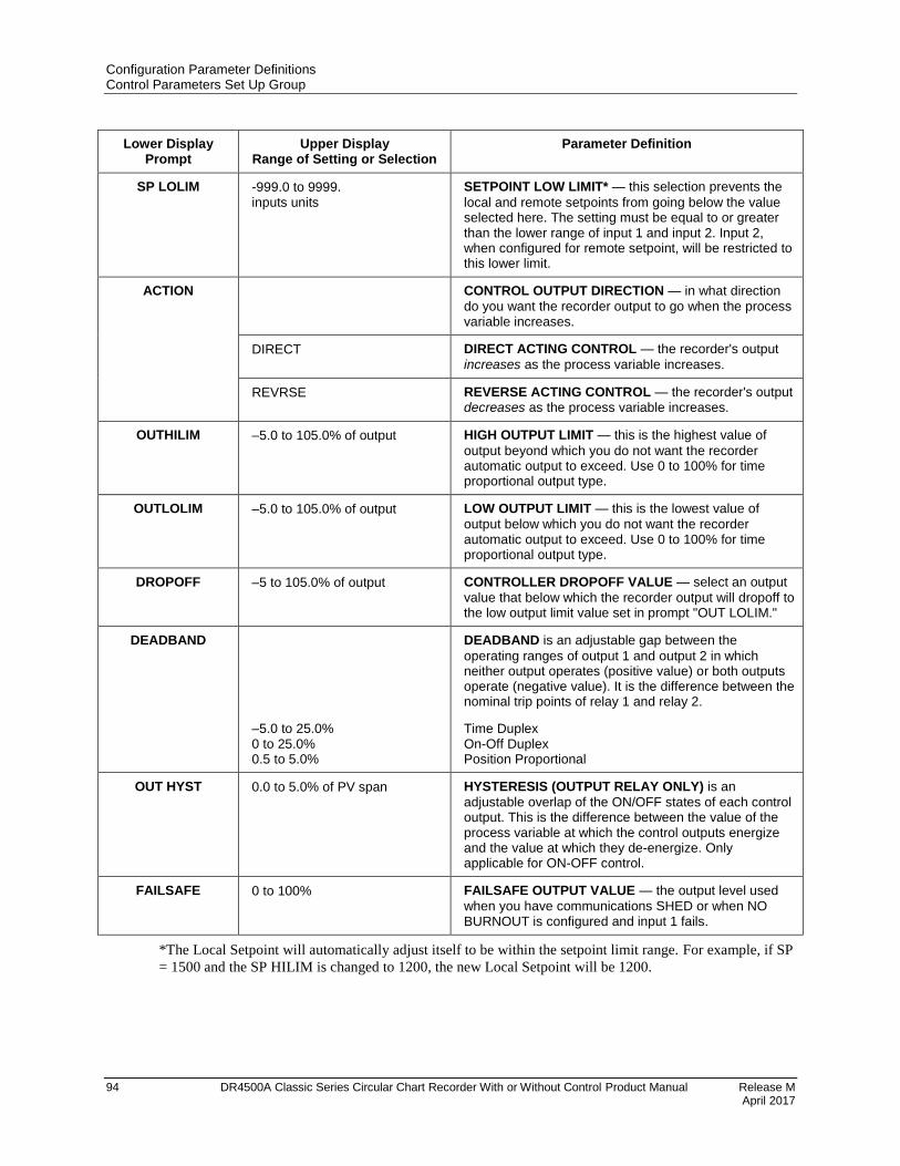
Configuration Parameter Definitions Control Parameters Set Up Group
94 DR4500A Classic Series Circular Chart Recorder With or Without Control Product Manual Release M April 2017
Lower Display Prompt
Upper Display Range of Setting or Selection
Parameter Definition
SP LOLIM -999.0 to 9999. inputs units
SETPOINT LOW LIMIT* — this selection prevents the
local and remote setpoints from going below the value selected here. The setting must be equal to or greater than the lower range of input 1 and input 2. Input 2, when configured for remote setpoint, will be restricted to this lower limit.
ACTION CONTROL OUTPUT DIRECTION — in what direction
do you want the recorder output to go when the process variable increases.
DIRECT DIRECT ACTING CONTROL — the recorder's output
increases as the process variable increases.
REVRSE REVERSE ACTING CONTROL — the recorder's output decreases as the process variable increases.
OUTHILIM –5.0 to 105.0% of output HIGH OUTPUT LIMIT — this is the highest value of
output beyond which you do not want the recorder automatic output to exceed. Use 0 to 100% for time proportional output type.
OUTLOLIM –5.0 to 105.0% of output LOW OUTPUT LIMIT — this is the lowest value of
output below which you do not want the recorder automatic output to exceed. Use 0 to 100% for time proportional output type.
DROPOFF –5 to 105.0% of output CONTROLLER DROPOFF VALUE — select an output
value that below which the recorder output will dropoff to the low output limit value set in prompt "OUT LOLIM."
DEADBAND
–5.0 to 25.0% 0 to 25.0% 0.5 to 5.0%
DEADBAND is an adjustable gap between the
operating ranges of output 1 and output 2 in which neither output operates (positive value) or both outputs operate (negative value). It is the difference between the nominal trip points of relay 1 and relay 2.
Time Duplex On-Off Duplex Position Proportional
OUT HYST 0.0 to 5.0% of PV span HYSTERESIS (OUTPUT RELAY ONLY) is an
adjustable overlap of the ON/OFF states of each control output. This is the difference between the value of the process variable at which the control outputs energize and the value at which they de-energize. Only applicable for ON-OFF control.
FAILSAFE 0 to 100% FAILSAFE OUTPUT VALUE — the output level used
when you have communications SHED or when NO BURNOUT is configured and input 1 fails.
*The Local Setpoint will automatically adjust itself to be within the setpoint limit range. For example, if SP
= 1500 and the SP HILIM is changed to 1200, the new Local Setpoint will be 1200.

Configuration Parameter Definitions Control Parameters Set Up Group
Release M DR4500A Classic Series Circular Chart Recorder With or Without Control Product Manual 95 April 2017
Lower Display Prompt
Upper Display Range of Setting or Selection
Parameter Definition
REM SW REM SW2
REMOTE SWITCHING (DIGITAL INPUT) — contact
closure enables one of the following:
NONE NO DIGITAL INPUT SELECTION
TO MAN TO MANUAL — contact closure selects Manual mode.
TO LSP TO LOCAL SETPOINT — contact closure selects the
local setpoint.
TO 2SP TO LOCAL SETPOINT 2 — contact closure selects
local setpoint 2.
TO DIR TO DIRECT ACTION — contact closure selects Direct
Control Action.
RN/HLD RUN/HOLD — contact closure suspends setpoint
Ramp/Program. Contact open resumes.
TUNE AUTOTUNE — contact closure initiates Autotune.
TIMER TIMER — starts the timer, if enabled.
The Timer can also be started by the RH KEY or ALARM2. These parameters are found under the Timer set up group.
MAN KEY
ENABLE
DISABL
MANUAL MODE KEY SELECTION — make selection
to enable or disable the Manual Mode selection through the MAN/AUTO key.
ENABLE — allows you to use the MAN/AUTO key to
select Manual Mode.
DISABLE — disables the MAN/AUTO key.
PB or GAIN PROPORTIONAL BAND UNITS — select one of the
following for the Proportional (P) term of the PID algorithm:
PB PCT PROPORTIONAL BAND — selects units of percent
proportional band for the P term of the PID algorithm, where:
PB% = 100%FS GAIN
GAIN
(must be used with settings of TIME D (TIME DUPLEX) or TI CUR (TIME CURRENT)
GAIN selects the unitless term of gain for the P term
of the PID algorithm, where:
GAIN =100%FS PB%
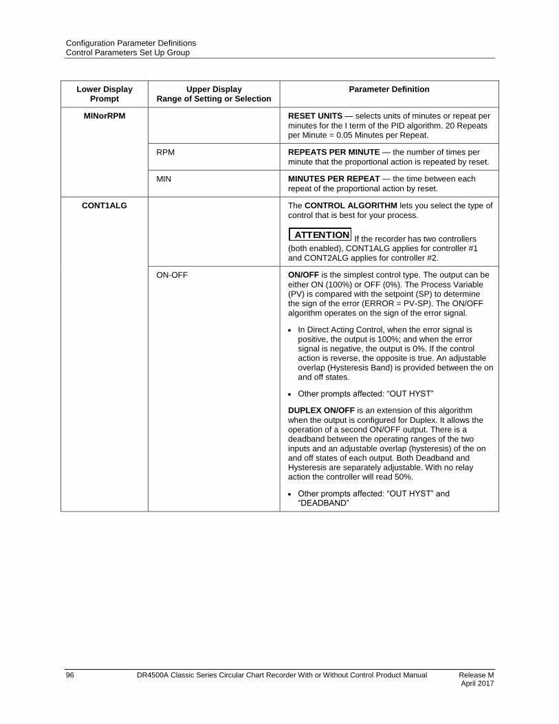
Configuration Parameter Definitions Control Parameters Set Up Group
96 DR4500A Classic Series Circular Chart Recorder With or Without Control Product Manual Release M April 2017
Lower Display Prompt
Upper Display Range of Setting or Selection
Parameter Definition
MINorRPM RESET UNITS — selects units of minutes or repeat per
minutes for the I term of the PID algorithm. 20 Repeats per Minute = 0.05 Minutes per Repeat.
RPM REPEATS PER MINUTE — the number of times per
minute that the proportional action is repeated by reset.
MIN MINUTES PER REPEAT — the time between each
repeat of the proportional action by reset.
CONT1ALG The CONTROL ALGORITHM lets you select the type of
control that is best for your process.
ATTENTION If the recorder has two controllers (both enabled), CONT1ALG applies for controller #1 and CONT2ALG applies for controller #2.
ON-OFF ON/OFF is the simplest control type. The output can be
either ON (100%) or OFF (0%). The Process Variable (PV) is compared with the setpoint (SP) to determine the sign of the error (ERROR = PV-SP). The ON/OFF algorithm operates on the sign of the error signal.
In Direct Acting Control, when the error signal is positive, the output is 100%; and when the error signal is negative, the output is 0%. If the control action is reverse, the opposite is true. An adjustable overlap (Hysteresis Band) is provided between the on and off states.
Other prompts affected: “OUT HYST”
DUPLEX ON/OFF is an extension of this algorithm
when the output is configured for Duplex. It allows the operation of a second ON/OFF output. There is a deadband between the operating ranges of the two inputs and an adjustable overlap (hysteresis) of the on and off states of each output. Both Deadband and Hysteresis are separately adjustable. With no relay action the controller will read 50%.
Other prompts affected: “OUT HYST” and “DEADBAND”
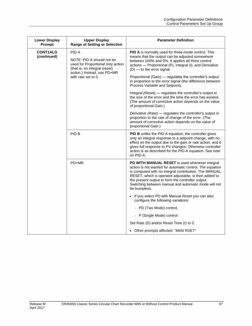
Configuration Parameter Definitions Control Parameters Set Up Group
Release M DR4500A Classic Series Circular Chart Recorder With or Without Control Product Manual 97 April 2017
Lower Display Prompt
Upper Display Range of Setting or Selection
Parameter Definition
CONT1ALG (continued)
PID A
NOTE: PID A should not be used for Proportional only action (that is, no integral (reset) action.) Instead, use PD+MR with rate set to 0.
PID A is normally used for three-mode control. This
means that the output can be adjusted somewhere between 100% and 0%. It applies all three control actions — Proportional (P), Integral (I), and Derivative (D) — to the error signal.
Proportional (Gain) — regulates the controller’s output
in proportion to the error signal (the difference between Process Variable and Setpoint).
Integral (Reset) — regulates the controller's output to the size of the error and the time the error has existed. (The amount of corrective action depends on the value of proportional Gain.)
Derivative (Rate) — regulates the controller's output in
proportion to the rate of change of the error. (The amount of corrective action depends on the value of proportional Gain.)
PID B PID B unlike the PID-A equation, the controller gives
only an integral response to a setpoint change, with no effect on the output due to the gain or rate action, and it gives full response to PV changes. Otherwise controller action is as described for the PID-A equation. See note on PID-A.
PD+MR PD WITH MANUAL RESET is used whenever integral
action is not wanted for automatic control. The equation is computed with no integral contribution. The MANUAL RESET, which is operator adjustable, is then added to the present output to form the controller output. Switching between manual and automatic mode will not be bumpless.
If you select PD with Manual Reset you can also configure the following variations:
PD (Two Mode) control,
P (Single Mode) control.
Set Rate (D) and/or Reset Time (I) to 0.
Other prompts affected: "MAN RSET"
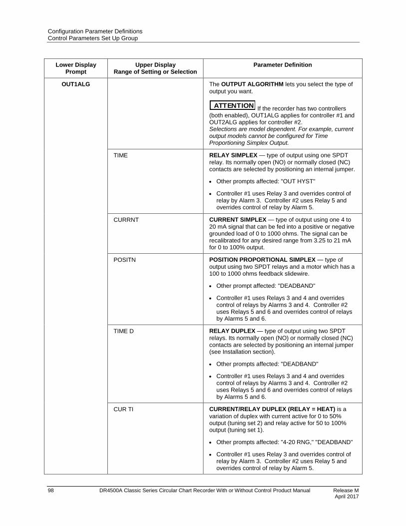
Configuration Parameter Definitions Control Parameters Set Up Group
98 DR4500A Classic Series Circular Chart Recorder With or Without Control Product Manual Release M April 2017
Lower Display Prompt
Upper Display Range of Setting or Selection
Parameter Definition
OUT1ALG The OUTPUT ALGORITHM lets you select the type of
output you want.
ATTENTION If the recorder has two controllers (both enabled), OUT1ALG applies for controller #1 and OUT2ALG applies for controller #2. Selections are model dependent. For example, current output models cannot be configured for Time Proportioning Simplex Output.
TIME RELAY SIMPLEX — type of output using one SPDT
relay. Its normally open (NO) or normally closed (NC) contacts are selected by positioning an internal jumper.
Other prompts affected: "OUT HYST"
Controller #1 uses Relay 3 and overrides control of relay by Alarm 3. Controller #2 uses Relay 5 and overrides control of relay by Alarm 5.
CURRNT CURRENT SIMPLEX — type of output using one 4 to
20 mA signal that can be fed into a positive or negative grounded load of 0 to 1000 ohms. The signal can be recalibrated for any desired range from 3.25 to 21 mA for 0 to 100% output.
POSITN POSITION PROPORTIONAL SIMPLEX — type of
output using two SPDT relays and a motor which has a 100 to 1000 ohms feedback slidewire.
Other prompt affected: "DEADBAND"
Controller #1 uses Relays 3 and 4 and overrides control of relays by Alarms 3 and 4. Controller #2 uses Relays 5 and 6 and overrides control of relays by Alarms 5 and 6.
TIME D RELAY DUPLEX — type of output using two SPDT
relays. Its normally open (NO) or normally closed (NC) contacts are selected by positioning an internal jumper (see Installation section).
Other prompts affected: "DEADBAND"
Controller #1 uses Relays 3 and 4 and overrides control of relays by Alarms 3 and 4. Controller #2 uses Relays 5 and 6 and overrides control of relays by Alarms 5 and 6.
CUR TI CURRENT/RELAY DUPLEX (RELAY = HEAT) is a
variation of duplex with current active for 0 to 50% output (tuning set 2) and relay active for 50 to 100% output (tuning set 1).
Other prompts affected: "4-20 RNG," "DEADBAND"
Controller #1 uses Relay 3 and overrides control of relay by Alarm 3. Controller #2 uses Relay 5 and overrides control of relay by Alarm 5.

Configuration Parameter Definitions Control Parameters Set Up Group
Release M DR4500A Classic Series Circular Chart Recorder With or Without Control Product Manual 99 April 2017
Lower Display Prompt
Upper Display Range of Setting or Selection
Parameter Definition
OUT1ALG (continued)
TI CUR RELAY/CURRENT DUPLEX (RELAY = COOL) is
similar to "CUR-TI" except that current is active for 50 to 100% and relay is active for 0 to 50%.
Other prompts affected: "4-20 RNG," "DEADBAND"
Controller #1 uses Relay 4 and overrides control of relay by Alarm 4. Controller #2 uses Relay 6 and overrides control of relay by Alarm 6.
4-20 RNG CURRENT DUPLEX RANGE ALGORITHM — used
with Output Algorithm selections "CUR-TI" or "TI-CUR."
50 PCT CURRENT DUPLEX RANGE (SPLIT) enables the
normal control current output to provide its full range for 50% output change.
If “CUR-TI” duplex was selected, the current output provides cool control.
100PCT CURRENT DUPLEX RANGE (FULL) enables the
normal control current output to provide duplex heat control over 0-100% output change and the relay output to provide cool control.
Repeat this procedure for CONTROL 2 configuration.
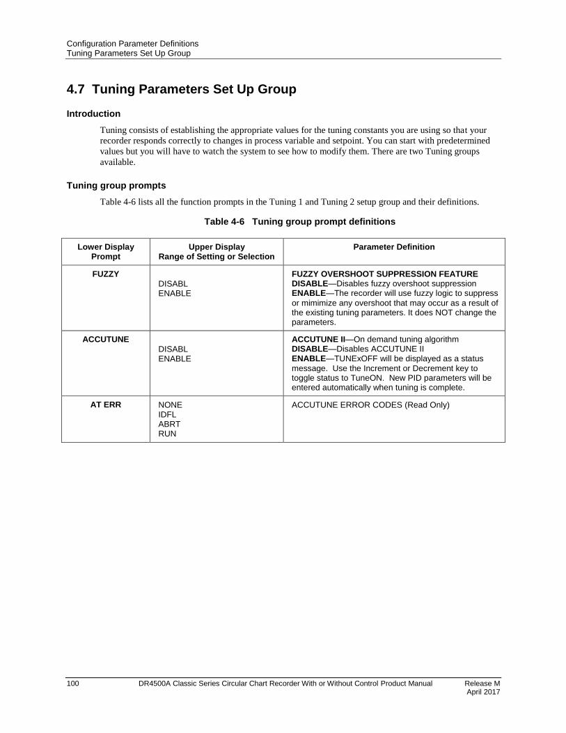
Configuration Parameter Definitions Tuning Parameters Set Up Group
100 DR4500A Classic Series Circular Chart Recorder With or Without Control Product Manual Release M April 2017
4.7 Tuning Parameters Set Up Group
Introduction
Tuning consists of establishing the appropriate values for the tuning constants you are using so that your
recorder responds correctly to changes in process variable and setpoint. You can start with predetermined
values but you will have to watch the system to see how to modify them. There are two Tuning groups
available.
Tuning group prompts
Table 4-6 lists all the function prompts in the Tuning 1 and Tuning 2 setup group and their definitions.
Table 4-6 Tuning group prompt definitions
Lower Display Prompt
Upper Display Range of Setting or Selection
Parameter Definition
FUZZY DISABL ENABLE
FUZZY OVERSHOOT SUPPRESSION FEATURE DISABLE—Disables fuzzy overshoot suppression ENABLE—The recorder will use fuzzy logic to suppress
or mimimize any overshoot that may occur as a result of the existing tuning parameters. It does NOT change the parameters.
ACCUTUNE DISABL ENABLE
ACCUTUNE II—On demand tuning algorithm DISABLE—Disables ACCUTUNE II ENABLE—TUNExOFF will be displayed as a status
message. Use the Increment or Decrement key to toggle status to TuneON. New PID parameters will be entered automatically when tuning is complete.
AT ERR NONE IDFL ABRT RUN
ACCUTUNE ERROR CODES (Read Only)
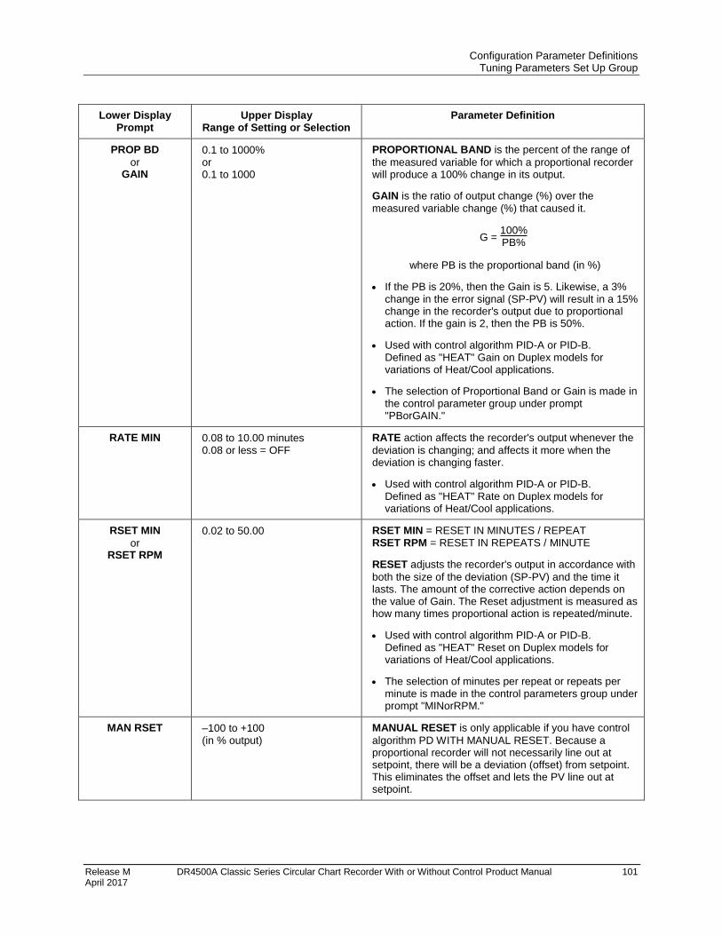
Configuration Parameter Definitions Tuning Parameters Set Up Group
Release M DR4500A Classic Series Circular Chart Recorder With or Without Control Product Manual 101 April 2017
Lower Display Prompt
Upper Display Range of Setting or Selection
Parameter Definition
PROP BD
or GAIN
0.1 to 1000% or 0.1 to 1000
PROPORTIONAL BAND is the percent of the range of
the measured variable for which a proportional recorder will produce a 100% change in its output.
GAIN is the ratio of output change (%) over the
measured variable change (%) that caused it.
G = 100%PB%
where PB is the proportional band (in %)
If the PB is 20%, then the Gain is 5. Likewise, a 3% change in the error signal (SP-PV) will result in a 15% change in the recorder's output due to proportional action. If the gain is 2, then the PB is 50%.
Used with control algorithm PID-A or PID-B. Defined as "HEAT" Gain on Duplex models for variations of Heat/Cool applications.
The selection of Proportional Band or Gain is made in the control parameter group under prompt "PBorGAIN."
RATE MIN 0.08 to 10.00 minutes 0.08 or less = OFF
RATE action affects the recorder's output whenever the
deviation is changing; and affects it more when the deviation is changing faster.
Used with control algorithm PID-A or PID-B. Defined as "HEAT" Rate on Duplex models for variations of Heat/Cool applications.
RSET MIN
or RSET RPM
0.02 to 50.00 RSET MIN = RESET IN MINUTES / REPEAT RSET RPM = RESET IN REPEATS / MINUTE
RESET adjusts the recorder's output in accordance with
both the size of the deviation (SP-PV) and the time it lasts. The amount of the corrective action depends on the value of Gain. The Reset adjustment is measured as how many times proportional action is repeated/minute.
Used with control algorithm PID-A or PID-B. Defined as "HEAT" Reset on Duplex models for variations of Heat/Cool applications.
The selection of minutes per repeat or repeats per minute is made in the control parameters group under prompt "MINorRPM."
MAN RSET –100 to +100 (in % output)
MANUAL RESET is only applicable if you have control
algorithm PD WITH MANUAL RESET. Because a proportional recorder will not necessarily line out at setpoint, there will be a deviation (offset) from setpoint. This eliminates the offset and lets the PV line out at setpoint.
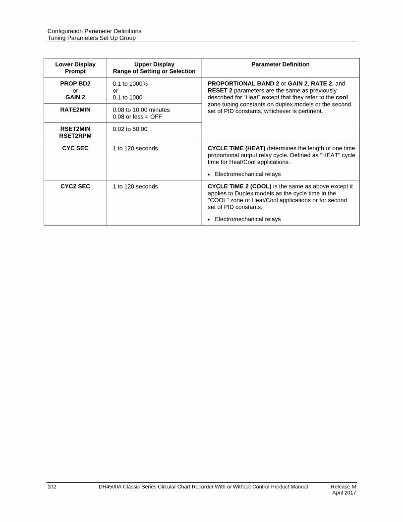
Configuration Parameter Definitions Tuning Parameters Set Up Group
102 DR4500A Classic Series Circular Chart Recorder With or Without Control Product Manual Release M April 2017
Lower Display Prompt
Upper Display Range of Setting or Selection
Parameter Definition
PROP BD2
or GAIN 2
0.1 to 1000% or 0.1 to 1000
PROPORTIONAL BAND 2 or GAIN 2, RATE 2, and RESET 2 parameters are the same as previously described for “Heat” except that they refer to the cool
zone tuning constants on duplex models or the second set of PID constants, whichever is pertinent. RATE2MIN 0.08 to 10.00 minutes
0.08 or less = OFF
RSET2MIN RSET2RPM
0.02 to 50.00
CYC SEC 1 to 120 seconds CYCLE TIME (HEAT) determines the length of one time
proportional output relay cycle. Defined as "HEAT" cycle time for Heat/Cool applications.
Electromechanical relays
CYC2 SEC 1 to 120 seconds CYCLE TIME 2 (COOL) is the same as above except it
applies to Duplex models as the cycle time in the "COOL" zone of Heat/Cool applications or for second set of PID constants.
Electromechanical relays

Configuration Parameter Definitions Setpoint Ramp Set Up Group
Release M DR4500A Classic Series Circular Chart Recorder With or Without Control Product Manual 103 April 2017
4.8 Setpoint Ramp Set Up Group
Introduction
The Setpoint Ramp 1 and 2 Set Up groups contain the Function parameters that enable you to configure
two setpoints. Each setpoint (SP RAMP 1 and SP RAMP 2) can be configured only one of three ways:
ramp, rate, or setpoint program.
Single Setpoint Ramp
Setpoint will ramp between the current local setpoint and a final setpoint over a time interval of up to 255
minutes (SP RAMP).
Setpoint Rate
The Setpoint Ramp Set Up group also contains the function parameters that let you configure a specific rate
of change for any local setpoint change (SP RATE). It includes selections for Rate Up and Rate Down.
Setpoint Program
Also included under this group are prompts for configuring a 36-segment Setpoint program (SP PROG).
The prompts and instructions for Setpoint programming are presented in the Section 6 Setpoint Ramp/Soak
Programming Option.
You can start and stop the ramp/program using the RUN/HOLD key.
Setpoint Ramp/ Program group prompts
Table 4-7 lists all the function prompts in the Setpoint Ramp 1 or 2 setup group and their definitions.
When you enable the ramp type (SP RAMP, SP RATE, SP PROG) the other two types are hidden from the
display.
Table 4-7 Setpoint Ramp 1 or 2 group definitions
Lower Display Prompt
Upper Display Range of Setting or Selection
Parameter Definition
SP RAMP
ENABLE DISABL
SINGLE SETPOINT RAMP — Make selection to enable
or disable the setpoint ramp function. Make sure you configure a ramp time and a final setpoint value. “SP PROG” and “SP RATE” must be disabled.
ENABLE SETPOINT RAMP — Allows you to start the
setpoint ramp (in automatic mode).
DISABLE SETPOINT RAMP — Disables the setpoint
ramp.
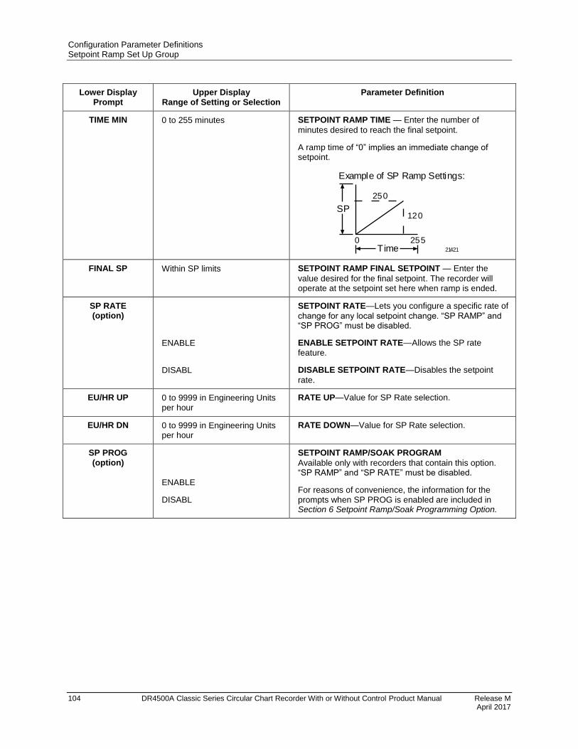
Configuration Parameter Definitions Setpoint Ramp Set Up Group
104 DR4500A Classic Series Circular Chart Recorder With or Without Control Product Manual Release M April 2017
Lower Display Prompt
Upper Display Range of Setting or Selection
Parameter Definition
TIME MIN 0 to 255 minutes SETPOINT RAMP TIME — Enter the number of
minutes desired to reach the final setpoint.
A ramp time of “0” implies an immediate change of setpoint.
SP
Time0 255
120
250
Example of SP Ramp Settings:
21421
FINAL SP Within SP limits SETPOINT RAMP FINAL SETPOINT — Enter the
value desired for the final setpoint. The recorder will operate at the setpoint set here when ramp is ended.
SP RATE (option)
ENABLE
DISABL
SETPOINT RATE—Lets you configure a specific rate of
change for any local setpoint change. “SP RAMP” and “SP PROG” must be disabled.
ENABLE SETPOINT RATE—Allows the SP rate
feature.
DISABLE SETPOINT RATE—Disables the setpoint
rate.
EU/HR UP 0 to 9999 in Engineering Units per hour
RATE UP—Value for SP Rate selection.
EU/HR DN 0 to 9999 in Engineering Units per hour
RATE DOWN—Value for SP Rate selection.
SP PROG (option)
ENABLE
DISABL
SETPOINT RAMP/SOAK PROGRAM
Available only with recorders that contain this option. “SP RAMP” and “SP RATE” must be disabled.
For reasons of convenience, the information for the prompts when SP PROG is enabled are included in Section 6 Setpoint Ramp/Soak Programming Option.

Configuration Parameter Definitions Timer Set Up Group
Release M DR4500A Classic Series Circular Chart Recorder With or Without Control Product Manual 105 April 2017
4.9 Timer Set Up Group
Introduction
The Timer gives a countdown or elapsed time, after which Relay 1 energizes. If Timer is enabled, it has
exclusive control over Relay 1; that is, Alarm 1 will not control the relay.
Timer group prompts
Table 4-8 lists all the function prompts in the Timer setup group and their definitions.
Table 4-8 Timer group definitions
Lower Display Prompt
Upper Display Range of Setting or Selection
Parameter Definition
TIMER ENABLE DISABL
Lets you enable or disable the timer option.
PERIOD 0:00 to 99:59 Configures the length of the timeout period (from 0 to 99 hours, 59 minutes).
START RH KEY ALARM 2
Selects whether the Timer starts with the keyboard (Run/Hold key) or Alarm 2.
The Timer can also be started by a discrete input, REM SW or REM SW2. These prompts are found under the Control Set Up Group.
LDISPLAY
TREM
ET
Select whether time remaining (TREM) or elapsed time (ET) is displayed for the timer option. The time is shown on the lower display in hh:mm format along with a rotating “clock” character.
Time remaining: If the “clock” rotation is clockwise,
elapsed time is indicated.
Elased time: If the “clock” rotation is counterclockwise,
time left is indicated.
RESET RH KEY ALARM 1 REPEAT
Selects whether the Timer resets with the keyboard (Run/Hold key) or Alarm 1. In Repeat Mode, the timer restarts immediately upon timeout and activates the relay for 1 to 5 seconds.
ON-TIME 1 SEC 2 SEC 3 SEC 4 SEC 5 SEC
Relay 1 on-time when timer is in repeat mode.
INCRMENT MINUTE SECOND
Selects the units of the timer.
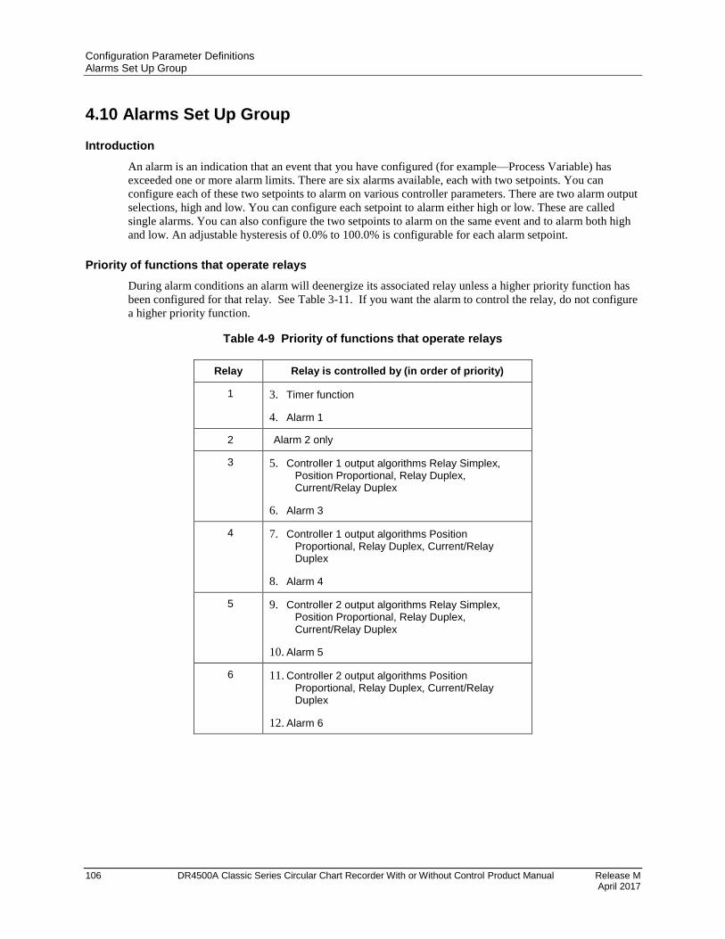
Configuration Parameter Definitions Alarms Set Up Group
106 DR4500A Classic Series Circular Chart Recorder With or Without Control Product Manual Release M April 2017
4.10 Alarms Set Up Group
Introduction
An alarm is an indication that an event that you have configured (for example—Process Variable) has
exceeded one or more alarm limits. There are six alarms available, each with two setpoints. You can
configure each of these two setpoints to alarm on various controller parameters. There are two alarm output
selections, high and low. You can configure each setpoint to alarm either high or low. These are called
single alarms. You can also configure the two setpoints to alarm on the same event and to alarm both high
and low. An adjustable hysteresis of 0.0% to 100.0% is configurable for each alarm setpoint.
Priority of functions that operate relays
During alarm conditions an alarm will deenergize its associated relay unless a higher priority function has
been configured for that relay. See Table 3-11. If you want the alarm to control the relay, do not configure
a higher priority function.
Table 4-9 Priority of functions that operate relays
Relay Relay is controlled by (in order of priority)
1 3. Timer function
4. Alarm 1
2 Alarm 2 only
3 5. Controller 1 output algorithms Relay Simplex, Position Proportional, Relay Duplex, Current/Relay Duplex
6. Alarm 3
4 7. Controller 1 output algorithms Position Proportional, Relay Duplex, Current/Relay Duplex
8. Alarm 4
5 9. Controller 2 output algorithms Relay Simplex, Position Proportional, Relay Duplex, Current/Relay Duplex
10. Alarm 5
6 11. Controller 2 output algorithms Position Proportional, Relay Duplex, Current/Relay Duplex
12. Alarm 6
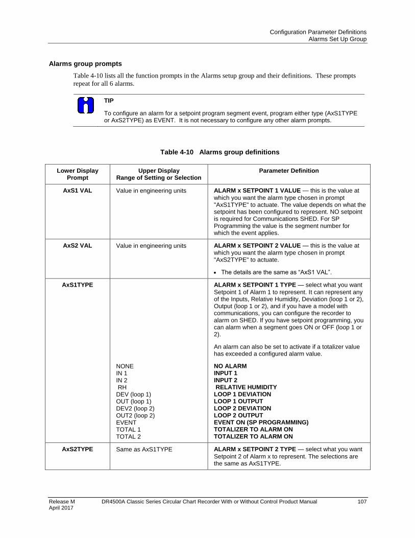
Configuration Parameter Definitions Alarms Set Up Group
Release M DR4500A Classic Series Circular Chart Recorder With or Without Control Product Manual 107 April 2017
Alarms group prompts
Table 4-10 lists all the function prompts in the Alarms setup group and their definitions. These prompts
repeat for all 6 alarms.
TIP
To configure an alarm for a setpoint program segment event, program either type (AxS1TYPE or AxS2TYPE) as EVENT. It is not necessary to configure any other alarm prompts.
Table 4-10 Alarms group definitions
Lower Display Prompt
Upper Display Range of Setting or Selection
Parameter Definition
AxS1 VAL Value in engineering units ALARM x SETPOINT 1 VALUE — this is the value at
which you want the alarm type chosen in prompt "AxS1TYPE" to actuate. The value depends on what the setpoint has been configured to represent. NO setpoint is required for Communications SHED. For SP Programming the value is the segment number for which the event applies.
AxS2 VAL Value in engineering units ALARM x SETPOINT 2 VALUE — this is the value at
which you want the alarm type chosen in prompt "AxS2TYPE" to actuate.
The details are the same as “AxS1 VAL”.
AxS1TYPE
NONE IN 1 IN 2 RH DEV (loop 1) OUT (loop 1) DEV2 (loop 2) OUT2 (loop 2) EVENT TOTAL 1 TOTAL 2
ALARM x SETPOINT 1 TYPE — select what you want
Setpoint 1 of Alarm 1 to represent. It can represent any of the Inputs, Relative Humidity, Deviation (loop 1 or 2), Output (loop 1 or 2), and if you have a model with communications, you can configure the recorder to alarm on SHED. If you have setpoint programming, you can alarm when a segment goes ON or OFF (loop 1 or 2).
An alarm can also be set to activate if a totalizer value has exceeded a configured alarm value.
NO ALARM INPUT 1 INPUT 2 RELATIVE HUMIDITY LOOP 1 DEVIATION LOOP 1 OUTPUT LOOP 2 DEVIATION LOOP 2 OUTPUT EVENT ON (SP PROGRAMMING) TOTALIZER TO ALARM ON TOTALIZER TO ALARM ON
AxS2TYPE Same as AxS1TYPE ALARM x SETPOINT 2 TYPE — select what you want
Setpoint 2 of Alarm x to represent. The selections are the same as AxS1TYPE.
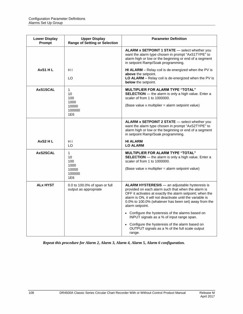
Configuration Parameter Definitions Alarms Set Up Group
108 DR4500A Classic Series Circular Chart Recorder With or Without Control Product Manual Release M April 2017
Lower Display Prompt
Upper Display Range of Setting or Selection
Parameter Definition
AxS1 H L
H I LO
ALARM x SETPOINT 1 STATE — select whether you
want the alarm type chosen in prompt "AxS1TYPE" to alarm high or low or the beginning or end of a segment in setpoint Ramp/Soak programming.
HI ALARM – Relay coil is de-energized when the PV is above the setpoint. LO ALARM – Relay coil is de-energized when the PV is below the setpoint.
AxS1SCAL 1 10 100 1000 10000 100000 1E6
MULTIPLIER FOR ALARM TYPE “TOTAL” SELECTION — the alarm is only a high value. Enter a
scaler of from 1 to 1000000.
(Base value x multiplier = alarm setpoint value)
AxS2 H L
H I LO
ALARM x SETPOINT 2 STATE — select whether you
want the alarm type chosen in prompt "AxS2TYPE" to alarm high or low or the beginning or end of a segment in setpoint Ramp/Soak programming.
HI ALARM LO ALARM
AxS2SCAL 1 10 100 1000 10000 100000 1E6
MULTIPLIER FOR ALARM TYPE “TOTAL” SELECTION — the alarm is only a high value. Enter a
scaler of from 1 to 1000000.
(Base value x multiplier = alarm setpoint value)
ALx HYST 0.0 to 100.0% of span or full output as appropriate
ALARM HYSTERESIS — an adjustable hysteresis is
provided on each alarm such that when the alarm is OFF it activates at exactly the alarm setpoint; when the alarm is ON, it will not deactivate until the variable is 0.0% to 100.0% (whatever has been set) away from the alarm setpoint.
Configure the hysteresis of the alarms based on INPUT signals as a % of input range span.
Configure the hysteresis of the alarm based on OUTPUT signals as a % of the full scale output range.
Repeat this procedure for Alarm 2, Alarm 3, Alarm 4, Alarm 5, Alarm 6 configuration.
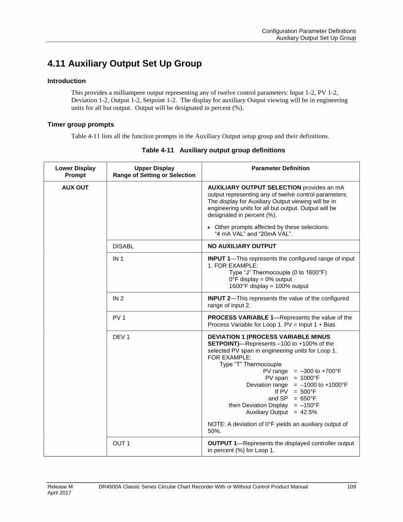
Configuration Parameter Definitions Auxiliary Output Set Up Group
Release M DR4500A Classic Series Circular Chart Recorder With or Without Control Product Manual 109 April 2017
4.11 Auxiliary Output Set Up Group
Introduction
This provides a milliampere output representing any of twelve control parameters: Input 1-2, PV 1-2,
Deviation 1-2, Output 1-2, Setpoint 1-2. The display for auxiliary Output viewing will be in engineering
units for all but output. Output will be designated in percent (%).
Timer group prompts
Table 4-11 lists all the function prompts in the Auxiliary Output setup group and their definitions.
Table 4-11 Auxiliary output group definitions
Lower Display Prompt
Upper Display Range of Setting or Selection
Parameter Definition
AUX OUT AUXILIARY OUTPUT SELECTION provides an mA
output representing any of twelve control parameters. The display for Auxiliary Output viewing will be in engineering units for all but output. Output will be designated in percent (%).
Other prompts affected by these selections: “4 mA VAL” and “20mA VAL”.
DISABL NO AUXILIARY OUTPUT
IN 1 INPUT 1—This represents the configured range of input
1. FOR EXAMPLE: Type “J” Thermocouple (0 to 1600°F) 0°F display = 0% output 1600°F display = 100% output
IN 2 INPUT 2—This represents the value of the configured
range of input 2.
PV 1 PROCESS VARIABLE 1—Represents the value of the
Process Variable for Loop 1. PV = Input 1 + Bias
DEV 1 DEVIATION 1 (PROCESS VARIABLE MINUS SETPOINT)—Represents –100 to +100% of the
selected PV span in engineering units for Loop 1. FOR EXAMPLE: Type “T” Thermocouple PV range = –300 to +700°F PV span = 1000°F Deviation range = –1000 to +1000°F If PV = 500°F and SP = 650°F then Deviation Display = –150°F Auxiliary Output = 42.5%
NOTE: A deviation of 0°F yields an auxiliary output of 50%.
OUT 1 OUTPUT 1—Represents the displayed controller output
in percent (%) for Loop 1.
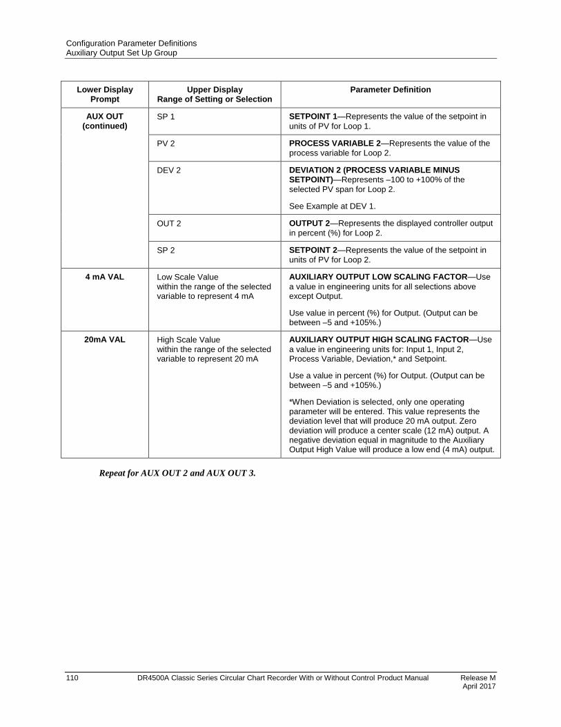
Configuration Parameter Definitions Auxiliary Output Set Up Group
110 DR4500A Classic Series Circular Chart Recorder With or Without Control Product Manual Release M April 2017
Lower Display Prompt
Upper Display Range of Setting or Selection
Parameter Definition
AUX OUT (continued)
SP 1 SETPOINT 1—Represents the value of the setpoint in
units of PV for Loop 1.
PV 2 PROCESS VARIABLE 2—Represents the value of the
process variable for Loop 2.
DEV 2 DEVIATION 2 (PROCESS VARIABLE MINUS SETPOINT)—Represents –100 to +100% of the
selected PV span for Loop 2.
See Example at DEV 1.
OUT 2 OUTPUT 2—Represents the displayed controller output
in percent (%) for Loop 2.
SP 2 SETPOINT 2—Represents the value of the setpoint in
units of PV for Loop 2.
4 mA VAL Low Scale Value within the range of the selected variable to represent 4 mA
AUXILIARY OUTPUT LOW SCALING FACTOR—Use
a value in engineering units for all selections above except Output.
Use value in percent (%) for Output. (Output can be between –5 and +105%.)
20mA VAL High Scale Value within the range of the selected variable to represent 20 mA
AUXILIARY OUTPUT HIGH SCALING FACTOR—Use
a value in engineering units for: Input 1, Input 2, Process Variable, Deviation,* and Setpoint.
Use a value in percent (%) for Output. (Output can be between –5 and +105%.)
*When Deviation is selected, only one operating parameter will be entered. This value represents the deviation level that will produce 20 mA output. Zero deviation will produce a center scale (12 mA) output. A negative deviation equal in magnitude to the Auxiliary Output High Value will produce a low end (4 mA) output.
Repeat for AUX OUT 2 and AUX OUT 3.
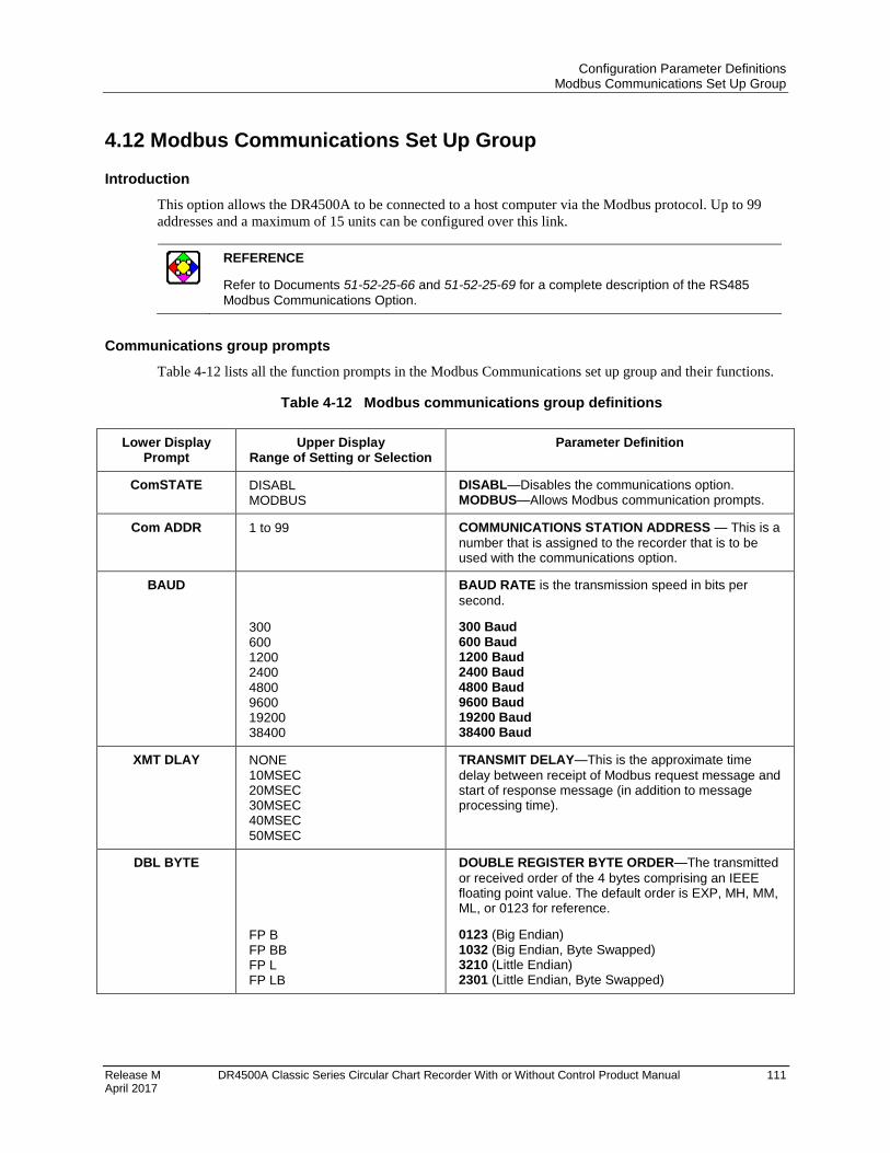
Configuration Parameter Definitions Modbus Communications Set Up Group
Release M DR4500A Classic Series Circular Chart Recorder With or Without Control Product Manual 111 April 2017
4.12 Modbus Communications Set Up Group
Introduction
This option allows the DR4500A to be connected to a host computer via the Modbus protocol. Up to 99
addresses and a maximum of 15 units can be configured over this link.
REFERENCE
Refer to Documents 51-52-25-66 and 51-52-25-69 for a complete description of the RS485
Modbus Communications Option.
Communications group prompts
Table 4-12 lists all the function prompts in the Modbus Communications set up group and their functions.
Table 4-12 Modbus communications group definitions
Lower Display Prompt
Upper Display Range of Setting or Selection
Parameter Definition
ComSTATE DISABL MODBUS
DISABL—Disables the communications option. MODBUS—Allows Modbus communication prompts.
Com ADDR 1 to 99 COMMUNICATIONS STATION ADDRESS — This is a
number that is assigned to the recorder that is to be used with the communications option.
BAUD
300 600 1200 2400 4800 9600 19200 38400
BAUD RATE is the transmission speed in bits per
second.
300 Baud 600 Baud 1200 Baud 2400 Baud 4800 Baud 9600 Baud 19200 Baud 38400 Baud
XMT DLAY NONE 10MSEC 20MSEC 30MSEC 40MSEC 50MSEC
TRANSMIT DELAY—This is the approximate time
delay between receipt of Modbus request message and start of response message (in addition to message processing time).
DBL BYTE
FP B FP BB FP L FP LB
DOUBLE REGISTER BYTE ORDER—The transmitted
or received order of the 4 bytes comprising an IEEE floating point value. The default order is EXP, MH, MM, ML, or 0123 for reference.
0123 (Big Endian) 1032 (Big Endian, Byte Swapped) 3210 (Little Endian) 2301 (Little Endian, Byte Swapped)
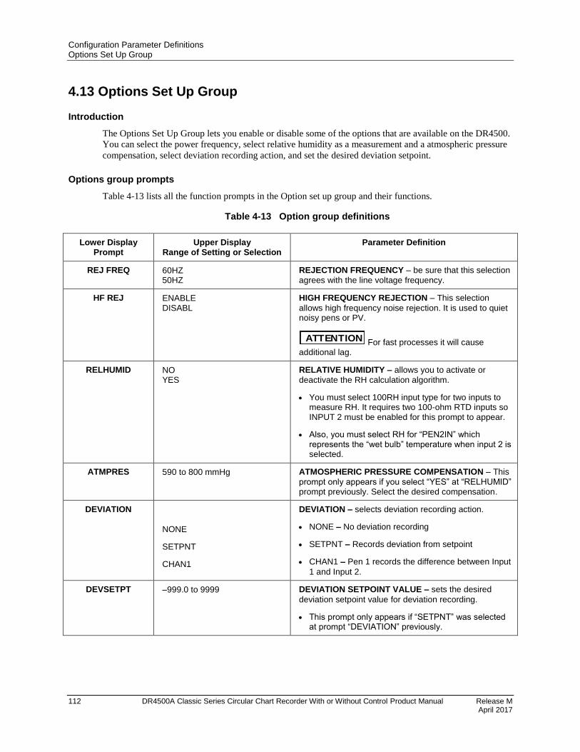
Configuration Parameter Definitions Options Set Up Group
112 DR4500A Classic Series Circular Chart Recorder With or Without Control Product Manual Release M April 2017
4.13 Options Set Up Group
Introduction
The Options Set Up Group lets you enable or disable some of the options that are available on the DR4500.
You can select the power frequency, select relative humidity as a measurement and a atmospheric pressure
compensation, select deviation recording action, and set the desired deviation setpoint.
Options group prompts
Table 4-13 lists all the function prompts in the Option set up group and their functions.
Table 4-13 Option group definitions
Lower Display Prompt
Upper Display Range of Setting or Selection
Parameter Definition
REJ FREQ 60HZ 50HZ
REJECTION FREQUENCY – be sure that this selection
agrees with the line voltage frequency.
HF REJ ENABLE DISABL
HIGH FREQUENCY REJECTION – This selection
allows high frequency noise rejection. It is used to quiet noisy pens or PV.
ATTENTION For fast processes it will cause additional lag.
RELHUMID NO YES
RELATIVE HUMIDITY – allows you to activate or
deactivate the RH calculation algorithm.
You must select 100RH input type for two inputs to measure RH. It requires two 100-ohm RTD inputs so INPUT 2 must be enabled for this prompt to appear.
Also, you must select RH for “PEN2IN” which represents the “wet bulb” temperature when input 2 is selected.
ATMPRES 590 to 800 mmHg ATMOSPHERIC PRESSURE COMPENSATION – This
prompt only appears if you select “YES” at “RELHUMID” prompt previously. Select the desired compensation.
DEVIATION NONE
SETPNT
CHAN1
DEVIATION – selects deviation recording action.
NONE – No deviation recording
SETPNT – Records deviation from setpoint
CHAN1 – Pen 1 records the difference between Input
1 and Input 2.
DEVSETPT –999.0 to 9999 DEVIATION SETPOINT VALUE – sets the desired
deviation setpoint value for deviation recording.
This prompt only appears if “SETPNT” was selected at prompt “DEVIATION” previously.
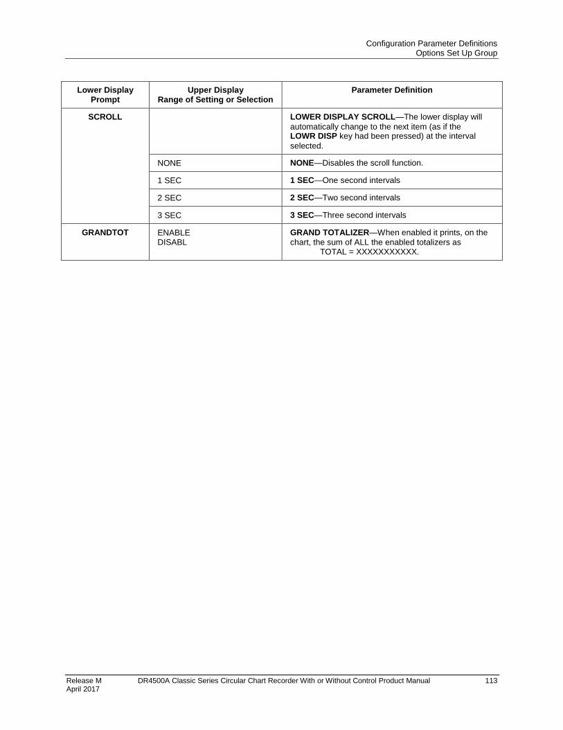
Configuration Parameter Definitions Options Set Up Group
Release M DR4500A Classic Series Circular Chart Recorder With or Without Control Product Manual 113 April 2017
Lower Display Prompt
Upper Display Range of Setting or Selection
Parameter Definition
SCROLL LOWER DISPLAY SCROLL—The lower display will
automatically change to the next item (as if the LOWR DISP key had been pressed) at the interval
selected.
NONE NONE—Disables the scroll function.
1 SEC 1 SEC—One second intervals
2 SEC 2 SEC—Two second intervals
3 SEC 3 SEC—Three second intervals
GRANDTOT ENABLE DISABL
GRAND TOTALIZER—When enabled it prints, on the
chart, the sum of ALL the enabled totalizers as TOTAL = XXXXXXXXXXX.
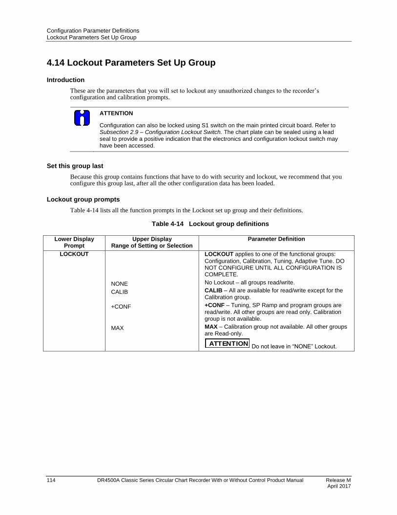
Configuration Parameter Definitions Lockout Parameters Set Up Group
114 DR4500A Classic Series Circular Chart Recorder With or Without Control Product Manual Release M April 2017
4.14 Lockout Parameters Set Up Group
Introduction
These are the parameters that you will set to lockout any unauthorized changes to the recorder’s configuration and calibration prompts.
ATTENTION
Configuration can also be locked using S1 switch on the main printed circuit board. Refer to Subsection 2.9 – Configuration Lockout Switch. The chart plate can be sealed using a lead seal to provide a positive indication that the electronics and configuration lockout switch may have been accessed.
Set this group last
Because this group contains functions that have to do with security and lockout, we recommend that you configure this group last, after all the other configuration data has been loaded.
Lockout group prompts
Table 4-14 lists all the function prompts in the Lockout set up group and their definitions.
Table 4-14 Lockout group definitions
Lower Display
Prompt Upper Display
Range of Setting or Selection Parameter Definition
LOCKOUT
NONE
CALIB
+CONF
MAX
LOCKOUT applies to one of the functional groups:
Configuration, Calibration, Tuning, Adaptive Tune. DO NOT CONFIGURE UNTIL ALL CONFIGURATION IS COMPLETE.
No Lockout – all groups read/write.
CALIB – All are available for read/write except for the Calibration group.
+CONF – Tuning, SP Ramp and program groups are
read/write. All other groups are read only. Calibration group is not available.
MAX – Calibration group not available. All other groups are Read-only.
ATTENTION Do not leave in “NONE” Lockout.
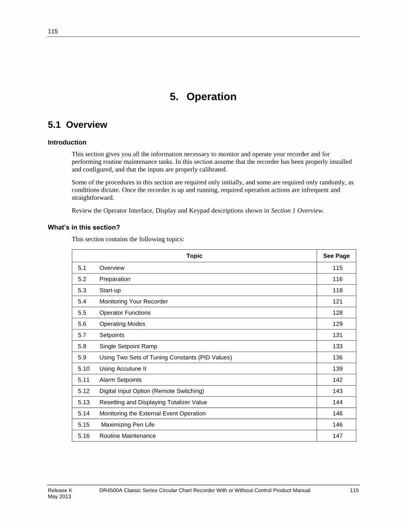
115
Release K DR4500A Classic Series Circular Chart Recorder With or Without Control Product Manual 115 May 2013
5. Operation
5.1 Overview
Introduction
This section gives you all the information necessary to monitor and operate your recorder and for
performing routine maintenance tasks. In this section assume that the recorder has been properly installed
and configured, and that the inputs are properly calibrated.
Some of the procedures in this section are required only initially, and some are required only randomly, as
conditions dictate. Once the recorder is up and running, required operation actions are infrequent and
straightforward.
Review the Operator Interface, Display and Keypad descriptions shown in Section 1 Overview.
What’s in this section?
This section contains the following topics:
Topic See Page
0H5.1 1HOverview 2H115
3H5.2 4HPreparation 5H116
6H5.3 7HStart-up 8H118
9H5.4 10HMonitoring Your Recorder 11H121
12H5.5 13HOperator Functions 14H128
15H5.6 Operating Modes 17H129
18H5.7 19HSetpoints 20H131
21H5.8 22HSingle Setpoint Ramp 23H133
24H5.9 25HUsing Two Sets of Tuning Constants (PID Values) 26H136
27H5.10 28HUsing Accutune II 29H139
30H5.11 31HAlarm Setpoints 32H142
33H5.12 34HDigital Input Option (Remote Switching) 35H143
36H5.13 37HResetting and Displaying Totalizer Value 38H144
39H5.14 40HMonitoring the External Event Operation 41H146
42H5.15 43H Maximizing Pen Life 44H146
45H5.16 46HRoutine Maintenance 47H147
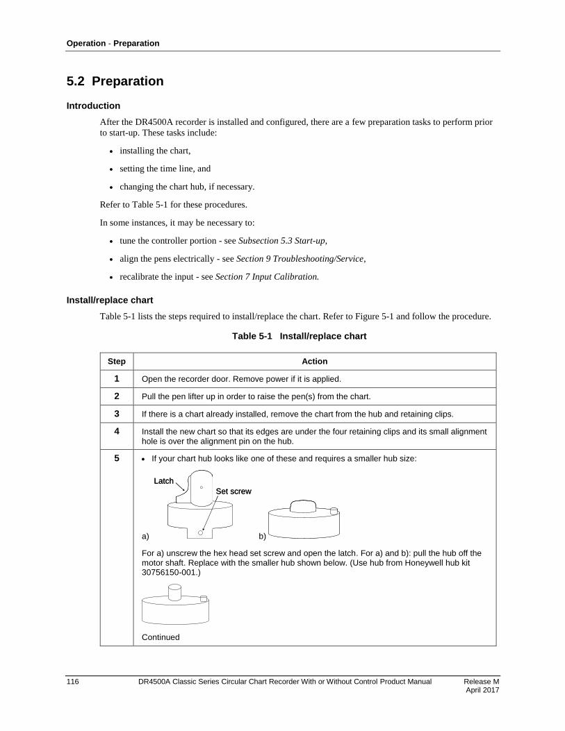
Operation - Preparation
116 DR4500A Classic Series Circular Chart Recorder With or Without Control Product Manual Release M April 2017
5.2 Preparation
Introduction
After the DR4500A recorder is installed and configured, there are a few preparation tasks to perform prior
to start-up. These tasks include:
installing the chart,
setting the time line, and
changing the chart hub, if necessary.
Refer to 48HTable 5-1 for these procedures.
In some instances, it may be necessary to:
tune the controller portion - see Subsection 49H5.3 50HStart-up,
align the pens electrically - see Section 9 Troubleshooting/Service,
recalibrate the input - see Section 7 Input Calibration.
Install/replace chart
51HTable 5-1 lists the steps required to install/replace the chart. Refer to 52HFigure 5-1 and follow the procedure.
Table 5-1 Install/replace chart
Step Action
1 Open the recorder door. Remove power if it is applied.
2 Pull the pen lifter up in order to raise the pen(s) from the chart.
3 If there is a chart already installed, remove the chart from the hub and retaining clips.
4 Install the new chart so that its edges are under the four retaining clips and its small alignment hole is over the alignment pin on the hub.
5 If your chart hub looks like one of these and requires a smaller hub size:
a)
Latch
Set screw
Latch
Set screw
b)
For a) unscrew the hex head set screw and open the latch. For a) and b): pull the hub off the motor shaft. Replace with the smaller hub shown below. (Use hub from Honeywell hub kit 30756150-001.)
Continued

Operation - Preparation
Release M DR4500A Classic Series Circular Chart Recorder With or Without Control Product Manual 117 April 2017
Step Action
5 If your chart hub looks like this and requires a smaller hub size:
then just pull the adapter hub off the chart hub to expose the smaller diameter hub.
Save the adapter hub for future use.
53HFigure 5-1 shows the location of the basic recording components.
Pen 1
Pen 2
Large chart hub adapter (pull
off to expose smaller hub)
Zero position
of pen arm
Chart
Engraved
time index
Captive
screw or
Lockout
screw
and plate
22087
Figure 5-1 Basic recording components
Removable chart hub

Operation - Start-up
118 DR4500A Classic Series Circular Chart Recorder With or Without Control Product Manual Release M April 2017
Set the Chart Time Line
54HTable 5-2 lists the steps required to set the chart time line.
Table 5-2 Set the chart time line procedure
Step Press Action/Result
1 Apply power and wait until the recorder runs its power-up tests.
2 CHART To enable the chart drive function.
or
To drive the chart forward
To drive the chart backward
until current chart time line aligns with engraved time index on the chart plate.
To increase forward drive speed, press and release the key while
holding in the key.
3 CHART To disable the chart drive function and return to normal operation.
5.3 Start-up
Preparation
Before start-up, there are two tasks to perform:
Install or replace the circular chart as described in 55H5.16 56HRoutine Maintenance.
Be sure that the configured settings for the current time and wake time (time at which recording begins)
are correct. Note that the recorder is “awake” during start-up to verify interaction with the process.
During start-up, you should verify the interaction between your process and the DR4500A recorder to be
sure that your process can tolerate some upsets during this procedure.
Diagnostic tests
When power is applied, the recorder will run four diagnostic tests. 57HTable 5-3 lists the four diagnostic tests.
Table 5-3 Power up diagnostic tests
Prompt on Lower Display Condition
RAM TEST Check RAM
CONFTEST (configuration checksum) Check nonvolatile memory
CAL TEST (working calibration) Check calibration
BATTERY Check the battery
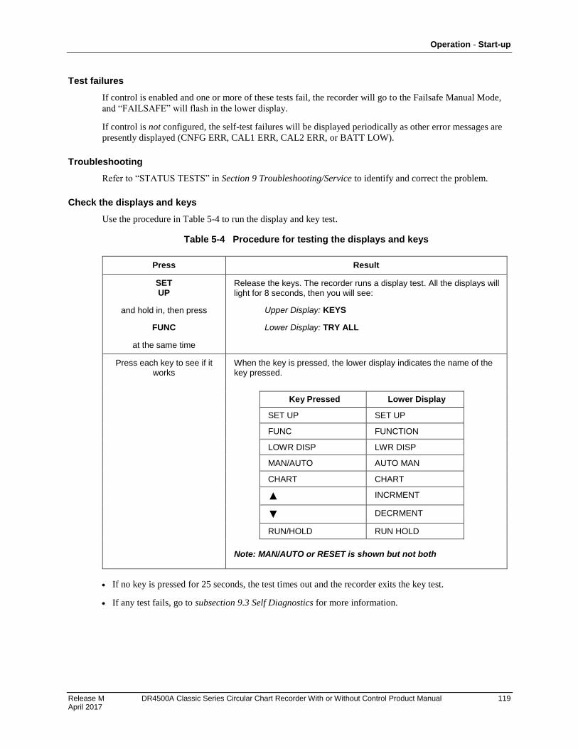
Operation - Start-up
Release M DR4500A Classic Series Circular Chart Recorder With or Without Control Product Manual 119 April 2017
Test failures
If control is enabled and one or more of these tests fail, the recorder will go to the Failsafe Manual Mode,
and “FAILSAFE” will flash in the lower display.
If control is not configured, the self-test failures will be displayed periodically as other error messages are
presently displayed (CNFG ERR, CAL1 ERR, CAL2 ERR, or BATT LOW).
Troubleshooting
Refer to “STATUS TESTS” in Section 9 Troubleshooting/Service to identify and correct the problem.
Check the displays and keys
Use the procedure in 58HTable 5-4 to run the display and key test.
Table 5-4 Procedure for testing the displays and keys
Press Result
SET UP
and hold in, then press
FUNC
at the same time
Release the keys. The recorder runs a display test. All the displays will light for 8 seconds, then you will see:
Upper Display: KEYS
Lower Display: TRY ALL
Press each key to see if it works
When the key is pressed, the lower display indicates the name of the key pressed.
Key Pressed Lower Display
SET UP SET UP
FUNC FUNCTION
LOWR DISP LWR DISP
MAN/AUTO AUTO MAN
CHART CHART
INCRMENT
DECRMENT
RUN/HOLD RUN HOLD
Note: MAN/AUTO or RESET is shown but not both
If no key is pressed for 25 seconds, the test times out and the recorder exits the key test.
If any test fails, go to subsection 9.3 Self Diagnostics for more information.
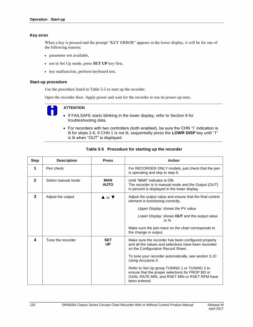
Operation - Start-up
120 DR4500A Classic Series Circular Chart Recorder With or Without Control Product Manual Release M April 2017
Key error
When a key is pressed and the prompt “KEY ERROR” appears in the lower display, it will be for one of
the following reasons:
parameter not available,
not in Set Up mode, press SET UP key first,
key malfunction, perform keyboard test.
Start-up procedure
Use the procedure listed in 59HTable 5-5 to start up the recorder.
Open the recorder door. Apply power and wait for the recorder to run its power-up tests.
ATTENTION
If FAILSAFE starts blinking in the lower display, refer to Section 9 for troubleshooting data.
For recorders with two controllers (both enabled), be sure the CHN ‘1’ indication is lit for steps 2-6. If CHN 1 is not lit, sequentially press the LOWR DISP key until “1” is lit when “OUT” is displayed.
Table 5-5 Procedure for starting up the recorder
Step Description Press Action
1 Pen check For RECORDER ONLY models, just check that the pen is operating and skip to step 6.
2 Select manual mode MAN AUTO
Until “MAN” indicator is ON. The recorder is in manual mode and the Output (OUT) in percent is displayed in the lower display.
3 Adjust the output or Adjust the output value and ensure that the final control element is functioning correctly.
Upper Display: shows the PV value
Lower Display: shows OUT and the output value
in %
Make sure the pen trace on the chart corresponds to the change in output.
4 Tune the recorder SET UP
Make sure the recorder has been configured properly and all the values and selections have been recorded on the Configuration Record Sheet.
To tune your recorder automatically, see section 60H5.10 61HUsing Accutune II.
Refer to Set Up group TUNING 1 or TUNING 2 to ensure that the proper selections for PROP BD or GAIN, RATE MIN, and RSET MIN or RSET RPM have been entered.
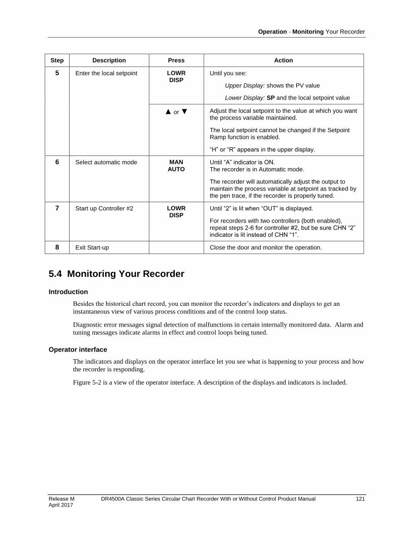
Operation - Monitoring Your Recorder
Release M DR4500A Classic Series Circular Chart Recorder With or Without Control Product Manual 121 April 2017
Step Description Press Action
5 Enter the local setpoint LOWR DISP
Until you see:
Upper Display: shows the PV value
Lower Display: SP and the local setpoint value
or Adjust the local setpoint to the value at which you want the process variable maintained.
The local setpoint cannot be changed if the Setpoint Ramp function is enabled.
“H” or “R” appears in the upper display.
6 Select automatic mode MAN AUTO
Until “A” indicator is ON. The recorder is in Automatic mode.
The recorder will automatically adjust the output to maintain the process variable at setpoint as tracked by the pen trace, if the recorder is properly tuned.
7 Start up Controller #2 LOWR DISP
Until “2” is lit when “OUT” is displayed.
For recorders with two controllers (both enabled), repeat steps 2-6 for controller #2, but be sure CHN “2” indicator is lit instead of CHN “1”.
8 Exit Start-up Close the door and monitor the operation.
5.4 Monitoring Your Recorder
Introduction
Besides the historical chart record, you can monitor the recorder’s indicators and displays to get an
instantaneous view of various process conditions and of the control loop status.
Diagnostic error messages signal detection of malfunctions in certain internally monitored data. Alarm and
tuning messages indicate alarms in effect and control loops being tuned.
Operator interface
The indicators and displays on the operator interface let you see what is happening to your process and how
the recorder is responding.
62HFigure 5-2 is a view of the operator interface. A description of the displays and indicators is included.
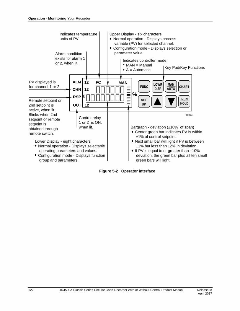
Operation - Monitoring Your Recorder
122 DR4500A Classic Series Circular Chart Recorder With or Without Control Product Manual Release M April 2017
22074
Control relay
1 or 2 is ON,
when lit.
ALM
CHN
RSP
OUT
12 FC
%RUN
HOLD
MAN
12
Lower Display - eight characters
Normal operation - Displays selectable
operating parameters and values.
Configuration mode - Displays function
group and parameters.
Remote setpoint or
2nd setpoint is
active, when lit.
Blinks when 2nd
setpoint or remote
setpoint is
obtained through
remote switch.
PV displayed is
for channel 1 or 2
Alarm condition
exists for alarm 1
or 2, when lit.
Indicates temperature
units of PV
Upper Display - six characters
Normal operation - Displays process
variable (PV) for selected channel.
Configuration mode - Displays selection or
parameter value.
Indicates controller mode:
MAN = Manual
A = Automatic
Bargraph - deviation (±10% of span)
Center green bar indicates PV is within
±1% of control setpoint.
Next small bar will light if PV is between
±1% but less than ±2% in deviation.
If PV is equal to or greater than ±10%
deviation, the green bar plus all ten small
green bars will light.
12
Key Pad/Key Functions
FUNCLOWR
DISP
MAN
AUTOCHART
SET
UP
Figure 5-2 Operator interface
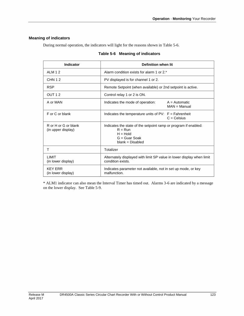
Operation - Monitoring Your Recorder
Release M DR4500A Classic Series Circular Chart Recorder With or Without Control Product Manual 123 April 2017
Meaning of indicators
During normal operation, the indicators will light for the reasons shown in 63HTable 5-6.
Table 5-6 Meaning of indicators
Indicator Definition when lit
ALM 1 2 Alarm condition exists for alarm 1 or 2.*
CHN 1 2 PV displayed is for channel 1 or 2.
RSP Remote Setpoint (when available) or 2nd setpoint is active.
OUT 1 2 Control relay 1 or 2 is ON.
A or MAN Indicates the mode of operation: A = Automatic MAN = Manual
F or C or blank Indicates the temperature units of PV: F = Fahrenheit C = Celsius
R or H or G or blank (in upper display)
Indicates the state of the setpoint ramp or program if enabled: R = Run H = Hold G = Guar Soak blank = Disabled
T Totalizer
LIMIT (in lower display)
Alternately displayed with limit SP value in lower display when limit condition exists.
KEY ERR (in lower display)
Indicates parameter not available, not in set up mode, or key malfunction.
* ALM1 indicator can also mean the Interval Timer has timed out. Alarms 3-6 are indicated by a message
on the lower display. See 64HTable 5-9.
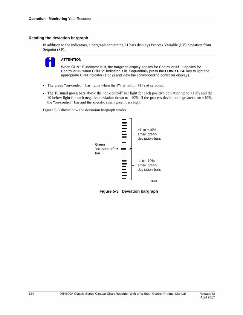
Operation - Monitoring Your Recorder
124 DR4500A Classic Series Circular Chart Recorder With or Without Control Product Manual Release M April 2017
Reading the deviation bargraph
In addition to the indicators, a bargraph containing 21 bars displays Process Variable (PV) deviation from
Setpoint (SP).
ATTENTION
When CHN “1” indicator is lit, the bargraph display applies for Controller #1. It applies for Controller #2 when CHN “2” indicator is lit. Sequentially press the LOWR DISP key to light the
appropriate CHN indicator (1 or 2) and view the corresponding controller displays.
The green “on-control” bar lights when the PV is within ±1% of setpoint.
The 10 small green bars above the “on-control” bar light for each positive deviation up to +10% and the
10 below light for each negative deviation down to –10%. If the process deviation is greater than ±10%,
the “on-control” bar and the specific small green bars light.
65HFigure 5-3 shows how the deviation bargraph works.
+1 to +10%
small green
dev iation bars
21424
-1 to -10%
small green
dev iation bars
Green
"on control"
bar
Figure 5-3 Deviation bargraph
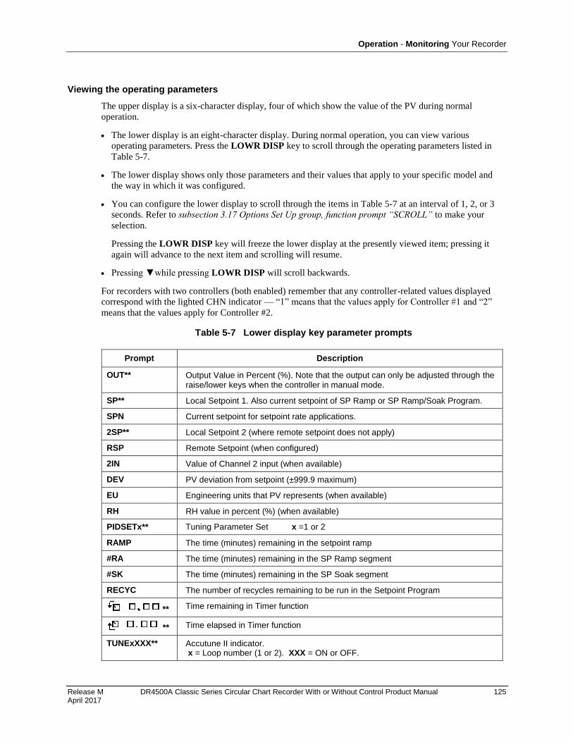
Operation - Monitoring Your Recorder
Release M DR4500A Classic Series Circular Chart Recorder With or Without Control Product Manual 125 April 2017
Viewing the operating parameters
The upper display is a six-character display, four of which show the value of the PV during normal
operation.
The lower display is an eight-character display. During normal operation, you can view various
operating parameters. Press the LOWR DISP key to scroll through the operating parameters listed in
66HTable 5-7.
The lower display shows only those parameters and their values that apply to your specific model and
the way in which it was configured.
You can configure the lower display to scroll through the items in 67HTable 5-7 at an interval of 1, 2, or 3
seconds. Refer to subsection 3.17 Options Set Up group, function prompt “SCROLL” to make your
selection.
Pressing the LOWR DISP key will freeze the lower display at the presently viewed item; pressing it
again will advance to the next item and scrolling will resume.
Pressing while pressing LOWR DISP will scroll backwards.
For recorders with two controllers (both enabled) remember that any controller-related values displayed
correspond with the lighted CHN indicator — “1” means that the values apply for Controller #1 and “2”
means that the values apply for Controller #2.
Table 5-7 Lower display key parameter prompts
Prompt Description
OUT** Output Value in Percent (%). Note that the output can only be adjusted through the raise/lower keys when the controller in manual mode.
SP** Local Setpoint 1. Also current setpoint of SP Ramp or SP Ramp/Soak Program.
SPN Current setpoint for setpoint rate applications.
2SP** Local Setpoint 2 (where remote setpoint does not apply)
RSP Remote Setpoint (when configured)
2IN Value of Channel 2 input (when available)
DEV PV deviation from setpoint (±999.9 maximum)
EU Engineering units that PV represents (when available)
RH RH value in percent (%) (when available)
PIDSETx** Tuning Parameter Set x =1 or 2
RAMP The time (minutes) remaining in the setpoint ramp
#RA The time (minutes) remaining in the SP Ramp segment
#SK The time (minutes) remaining in the SP Soak segment
RECYC The number of recycles remaining to be run in the Setpoint Program
** Time remaining in Timer function
** Time elapsed in Timer function
TUNExXXX** Accutune II indicator. x = Loop number (1 or 2). XXX = ON or OFF.

Operation - Monitoring Your Recorder
126 DR4500A Classic Series Circular Chart Recorder With or Without Control Product Manual Release M April 2017
Prompt Description
XXXXXX Totalization value—upper display shows TCHN1 (or 2) for totalization value 1 (or 2).
**You can press or to change the value of this parameter.
Diagnostic error messages
The DR4500A runs background tests to verify data and memory integrity. If there is a malfunction, an error
message will blink in the lower display. In the case of more than one simultaneous malfunction or alarm,
each message will be shown in succession.
A list of error messages is contained in 68HTable 5-8. If any of these error messages occur, refer to Section 9 -
Troubleshooting/Service for information to correct the failure.
Table 5-8 Error messages
Prompt Description
EE FAIL Unable to write to nonvolatile memory
FAILSAFE Failsafe
INP1FAIL Two consecutive failures of input 1 integration
INP2FAIL Two consecutive failures of input 2 integration
INP1 RNG INP2 RNG
Input out-of-range
PV LIMIT PV ±10% out-of-range
RV LIMIT Remote Variable out-of-range Note: RV = (input 2 x ratio) + bias
CNFG ERR Configuration data is in error.
CAL1 ERR Working CAL TEST failure (Control Output #1, Input 1, Input 2)
CAL2 ERR Working CAL TEST failure (Control Output #2)
BATT LOW Battery failure

Operation - Monitoring Your Recorder
Release M DR4500A Classic Series Circular Chart Recorder With or Without Control Product Manual 127 April 2017
Alarm and tuning messages
Alarms #3 through #6 and Accutune II for Control Loops #1 and #2 are indicated in the lower display.
In the case of more than one simultaneous diagnostic or alarm message, each message will be shown in
succession.
Table 5-9 Alarm and tuning messages
Prompt Description
ALARM 3 Indicates an alarm 3 action.
ALARM 4 Indicates an alarm 4 action.
ALARM 5 Indicates an alarm 5 action.
ALARM 6 Indicates an alarm 6 action.
TUNING 1 Indicates Accutune II in progress for Control Loop 1.
TUNING 2 Indicates Accutune II in progress for Control Loop 2.
ATTENTION
An active alarm will always provide an indication on the display but may not control its associated relay; that is, a higher priority function such as a control loop or timer may have control of the relay.
Operation - Operator Functions
128 DR4500A Classic Series Circular Chart Recorder With or Without Control Product Manual Release M April 2017
5.5 Operator Functions
Actions an operator can initiate
An operator can do the following:
Change the Control Mode (Auto/Man)
Adjust the Output Manually
Change the Setpoint
Switch between Setpoints
Run or Disable a Setpoint Ramp
Run or Disable a Setpoint Program
Switch between Two Sets of PID Values
Run or Disable Control Loop Tuning
Check the Alarm Setpoints
Display and Reset the Totalizer
Close a Remote Switch
Monitor External Event Pen Operation
Run a Key Test
Note that some actions depend upon how the recorder was configured and the features supplied on your
particular recorder model.
Refer to the following pages for functions and procedures.
CHN indicator
Remember, for recorders with two controllers (both enabled), any controller-related values displayed,
including control mode, correspond with the lighted CHN indicator — “1” means that the values apply for
Controller #1 and “2” means that the values apply for Controller #2. Sequentially press the LOWR DISP
key to scroll through the displays and light the appropriate CHN indicator for controller-related values.
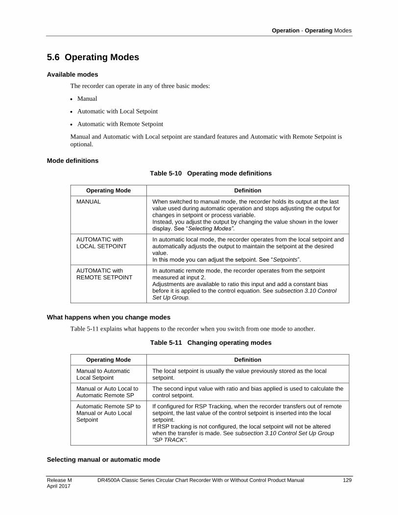
Operation - Operating Modes
Release M DR4500A Classic Series Circular Chart Recorder With or Without Control Product Manual 129 April 2017
5.6 Operating Modes
Available modes
The recorder can operate in any of three basic modes:
Manual
Automatic with Local Setpoint
Automatic with Remote Setpoint
Manual and Automatic with Local setpoint are standard features and Automatic with Remote Setpoint is
optional.
Mode definitions
Table 5-10 Operating mode definitions
Operating Mode Definition
MANUAL When switched to manual mode, the recorder holds its output at the last value used during automatic operation and stops adjusting the output for changes in setpoint or process variable. Instead, you adjust the output by changing the value shown in the lower display. See “Selecting Modes”.
AUTOMATIC with LOCAL SETPOINT
In automatic local mode, the recorder operates from the local setpoint and automatically adjusts the output to maintain the setpoint at the desired value. In this mode you can adjust the setpoint. See “Setpoints”.
AUTOMATIC with REMOTE SETPOINT
In automatic remote mode, the recorder operates from the setpoint measured at input 2. Adjustments are available to ratio this input and add a constant bias before it is applied to the control equation. See subsection 3.10 Control Set Up Group.
What happens when you change modes
69HTable 5-11 explains what happens to the recorder when you switch from one mode to another.
Table 5-11 Changing operating modes
Operating Mode Definition
Manual to Automatic Local Setpoint
The local setpoint is usually the value previously stored as the local setpoint.
Manual or Auto Local to Automatic Remote SP
The second input value with ratio and bias applied is used to calculate the control setpoint.
Automatic Remote SP to Manual or Auto Local Setpoint
If configured for RSP Tracking, when the recorder transfers out of remote setpoint, the last value of the control setpoint is inserted into the local setpoint. If RSP tracking is not configured, the local setpoint will not be altered when the transfer is made. See subsection 3.10 Control Set Up Group "SP TRACK".
Selecting manual or automatic mode
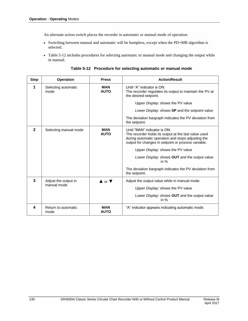
Operation - Operating Modes
130 DR4500A Classic Series Circular Chart Recorder With or Without Control Product Manual Release M April 2017
An alternate action switch places the recorder in automatic or manual mode of operation.
Switching between manual and automatic will be bumpless, except when the PD+MR algorithm is
selected.
70HTable 5-12 includes procedures for selecting automatic or manual mode and changing the output while
in manual.
Table 5-12 Procedure for selecting automatic or manual mode
Step Operation Press Action/Result
1 Selecting automatic mode
MAN AUTO
Until “A” indicator is ON. The recorder regulates its output to maintain the PV at the desired setpoint.
Upper Display: shows the PV value
Lower Display: shows SP and the setpoint value
The deviation bargraph indicates the PV deviation from the setpoint.
2 Selecting manual mode MAN AUTO
Until “MAN” indicator is ON. The recorder holds its output at the last value used during automatic operation and stops adjusting the output for changes in setpoint or process variable.
Upper Display: shows the PV value
Lower Display: shows OUT and the output value
in %
The deviation bargraph indicates the PV deviation from the setpoint.
3 Adjust the output in manual mode
or Adjust the output value while in manual mode.
Upper Display: shows the PV value
Lower Display: shows OUT and the output value
in %
4 Return to automatic mode
MAN AUTO
“A” indicator appears indicating automatic mode.
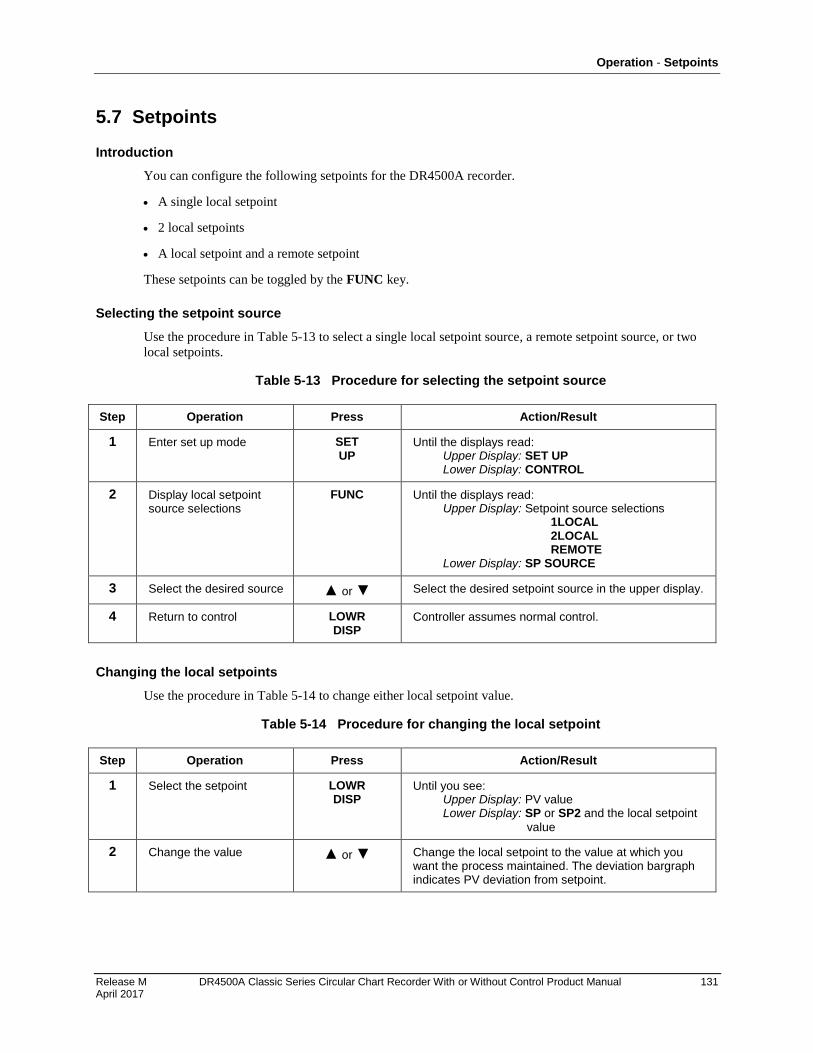
Operation - Setpoints
Release M DR4500A Classic Series Circular Chart Recorder With or Without Control Product Manual 131 April 2017
5.7 Setpoints
Introduction
You can configure the following setpoints for the DR4500A recorder.
A single local setpoint
2 local setpoints
A local setpoint and a remote setpoint
These setpoints can be toggled by the FUNC key.
Selecting the setpoint source
Use the procedure in 71HTable 5-13 to select a single local setpoint source, a remote setpoint source, or two
local setpoints.
Table 5-13 Procedure for selecting the setpoint source
Step Operation Press Action/Result
1 Enter set up mode SET UP
Until the displays read: Upper Display: SET UP Lower Display: CONTROL
2 Display local setpoint source selections
FUNC Until the displays read: Upper Display: Setpoint source selections 1LOCAL 2LOCAL REMOTE Lower Display: SP SOURCE
3 Select the desired source or Select the desired setpoint source in the upper display.
4 Return to control LOWR DISP
Controller assumes normal control.
Changing the local setpoints
Use the procedure in 72HTable 5-14 to change either local setpoint value.
Table 5-14 Procedure for changing the local setpoint
Step Operation Press Action/Result
1 Select the setpoint LOWR DISP
Until you see: Upper Display: PV value Lower Display: SP or SP2 and the local setpoint
value
2 Change the value or Change the local setpoint to the value at which you want the process maintained. The deviation bargraph indicates PV deviation from setpoint.
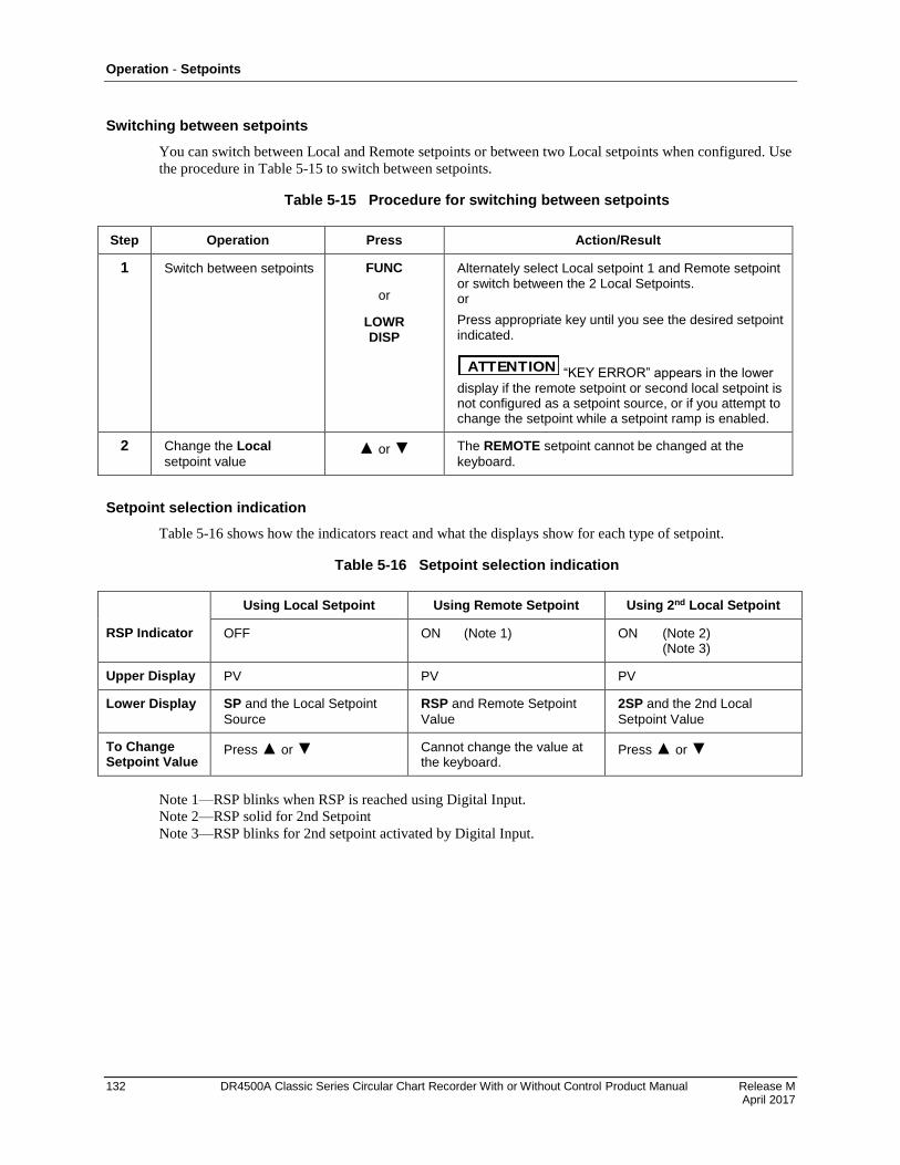
Operation - Setpoints
132 DR4500A Classic Series Circular Chart Recorder With or Without Control Product Manual Release M April 2017
Switching between setpoints
You can switch between Local and Remote setpoints or between two Local setpoints when configured. Use
the procedure in 73HTable 5-15 to switch between setpoints.
Table 5-15 Procedure for switching between setpoints
Step Operation Press Action/Result
1 Switch between setpoints FUNC
or
LOWR DISP
Alternately select Local setpoint 1 and Remote setpoint or switch between the 2 Local Setpoints. or
Press appropriate key until you see the desired setpoint indicated.
ATTENTION “KEY ERROR” appears in the lower display if the remote setpoint or second local setpoint is not configured as a setpoint source, or if you attempt to change the setpoint while a setpoint ramp is enabled.
2 Change the Local
setpoint value or The REMOTE setpoint cannot be changed at the
keyboard.
Setpoint selection indication
74HTable 5-16 shows how the indicators react and what the displays show for each type of setpoint.
Table 5-16 Setpoint selection indication
Using Local Setpoint Using Remote Setpoint Using 2nd Local Setpoint
RSP Indicator OFF ON (Note 1) ON (Note 2) (Note 3)
Upper Display PV PV PV
Lower Display SP and the Local Setpoint
Source
RSP and Remote Setpoint
Value
2SP and the 2nd Local
Setpoint Value
To Change Setpoint Value
Press or Cannot change the value at the keyboard.
Press or
Note 1—RSP blinks when RSP is reached using Digital Input.
Note 2—RSP solid for 2nd Setpoint
Note 3—RSP blinks for 2nd setpoint activated by Digital Input.
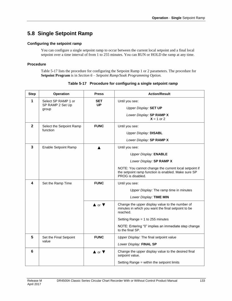
Operation - Single Setpoint Ramp
Release M DR4500A Classic Series Circular Chart Recorder With or Without Control Product Manual 133 April 2017
5.8 Single Setpoint Ramp
Configuring the setpoint ramp
You can configure a single setpoint ramp to occur between the current local setpoint and a final local
setpoint over a time interval of from 1 to 255 minutes. You can RUN or HOLD the ramp at any time.
Procedure
75HTable 5-17 lists the procedure for configuring the Setpoint Ramp 1 or 2 parameters. The procedure for
Setpoint Program is in Section 6 – Setpoint Ramp/Soak Programming Option.
Table 5-17 Procedure for configuring a single setpoint ramp
Step Operation Press Action/Result
1 Select SP RAMP 1 or SP RAMP 2 Set Up group
SET UP
Until you see:
Upper Display: SET UP
Lower Display: SP RAMP X X = 1 or 2
2 Select the Setpoint Ramp function
FUNC Until you see:
Upper Display: DISABL
Lower Display: SP RAMP X
3 Enable Setpoint Ramp Until you see:
Upper Display: ENABLE
Lower Display: SP RAMP X
NOTE: You cannot change the current local setpoint if the setpoint ramp function is enabled. Make sure SP PROG is disabled.
4 Set the Ramp Time FUNC Until you see:
Upper Display: The ramp time in minutes
Lower Display: TIME MIN
or Change the upper display value to the number of minutes in which you want the final setpoint to be reached.
Setting Range = 1 to 255 minutes
NOTE: Entering “0” implies an immediate step change to the final SP.
5 Set the Final Setpoint value
FUNC Upper Display: The final setpoint value
Lower Display: FINAL SP
6 or Change the upper display value to the desired final setpoint value.
Setting Range = within the setpoint limits
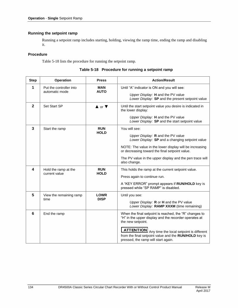
Operation - Single Setpoint Ramp
134 DR4500A Classic Series Circular Chart Recorder With or Without Control Product Manual Release M April 2017
Running the setpoint ramp
Running a setpoint ramp includes starting, holding, viewing the ramp time, ending the ramp and disabling
it.
Procedure
76HTable 5-18 lists the procedure for running the setpoint ramp.
Table 5-18 Procedure for running a setpoint ramp
Step Operation Press Action/Result
1 Put the controller into automatic mode
MAN AUTO
Until “A” indicator is ON and you will see:
Upper Display: H and the PV value Lower Display: SP and the present setpoint value
2 Set Start SP or Until the start setpoint value you desire is indicated in the lower display:
Upper Display: H and the PV value Lower Display: SP and the start setpoint value
3 Start the ramp RUN HOLD
You will see:
Upper Display: R and the PV value Lower Display: SP and a changing setpoint value
NOTE: The value in the lower display will be increasing or decreasing toward the final setpoint value.
The PV value in the upper display and the pen trace will also change.
4 Hold the ramp at the current value
RUN HOLD
This holds the ramp at the current setpoint value.
Press again to continue run.
A “KEY ERROR” prompt appears if RUN/HOLD key is
pressed while “SP RAMP” is disabled.
5 View the remaining ramp time
LOWR DISP
Until you see:
Upper Display: R or H and the PV value Lower Display: RAMP XXXM (time remaining)
6 End the ramp When the final setpoint is reached, the “R” changes to “H” in the upper display and the recorder operates at the new setpoint.
ATTENTION Any time the local setpoint is different from the final setpoint value and the RUN/HOLD key is
pressed, the ramp will start again.
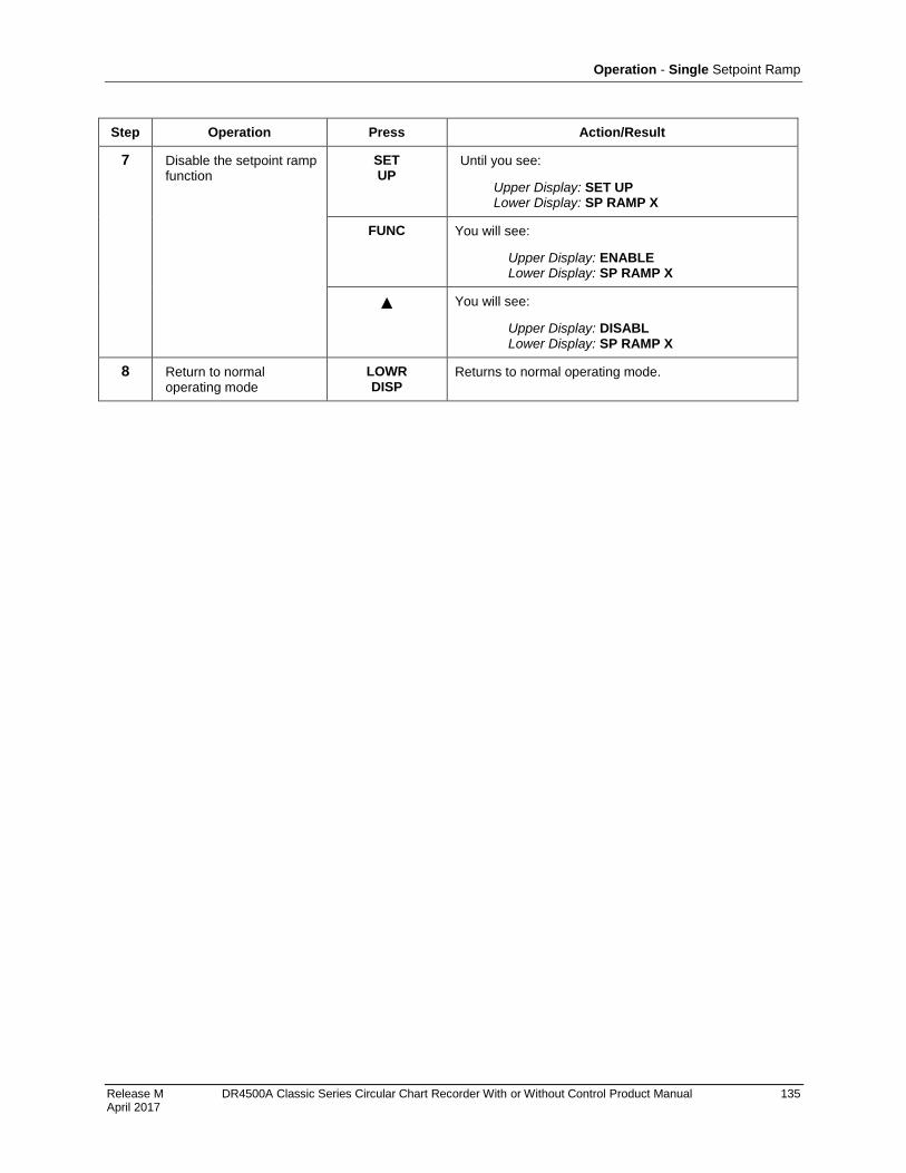
Operation - Single Setpoint Ramp
Release M DR4500A Classic Series Circular Chart Recorder With or Without Control Product Manual 135 April 2017
Step Operation Press Action/Result
7 Disable the setpoint ramp function
SET UP
Until you see:
Upper Display: SET UP Lower Display: SP RAMP X
FUNC You will see:
Upper Display: ENABLE Lower Display: SP RAMP X
You will see:
Upper Display: DISABL Lower Display: SP RAMP X
8 Return to normal operating mode
LOWR DISP
Returns to normal operating mode.
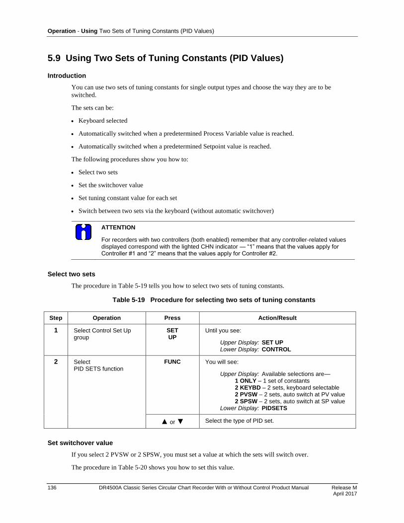
Operation - Using Two Sets of Tuning Constants (PID Values)
136 DR4500A Classic Series Circular Chart Recorder With or Without Control Product Manual Release M April 2017
5.9 Using Two Sets of Tuning Constants (PID Values)
Introduction
You can use two sets of tuning constants for single output types and choose the way they are to be
switched.
The sets can be:
Keyboard selected
Automatically switched when a predetermined Process Variable value is reached.
Automatically switched when a predetermined Setpoint value is reached.
The following procedures show you how to:
Select two sets
Set the switchover value
Set tuning constant value for each set
Switch between two sets via the keyboard (without automatic switchover)
ATTENTION
For recorders with two controllers (both enabled) remember that any controller-related values displayed correspond with the lighted CHN indicator — “1” means that the values apply for Controller #1 and “2” means that the values apply for Controller #2.
Select two sets
The procedure in 77HTable 5-19 tells you how to select two sets of tuning constants.
Table 5-19 Procedure for selecting two sets of tuning constants
Step Operation Press Action/Result
1 Select Control Set Up group
SET UP
Until you see:
Upper Display: SET UP Lower Display: CONTROL
2 Select PID SETS function
FUNC You will see:
Upper Display: Available selections are— 1 ONLY – 1 set of constants 2 KEYBD – 2 sets, keyboard selectable 2 PVSW – 2 sets, auto switch at PV value 2 SPSW – 2 sets, auto switch at SP value Lower Display: PIDSETS
or Select the type of PID set.
Set switchover value
If you select 2 PVSW or 2 SPSW, you must set a value at which the sets will switch over.
The procedure in 78HTable 5-20 shows you how to set this value.
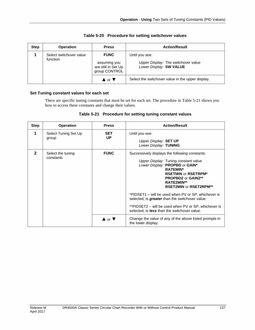
Operation - Using Two Sets of Tuning Constants (PID Values)
Release M DR4500A Classic Series Circular Chart Recorder With or Without Control Product Manual 137 April 2017
Table 5-20 Procedure for setting switchover values
Step Operation Press Action/Result
1 Select switchover value function
FUNC
assuming you are still in Set Up group CONTROL
Until you see:
Upper Display: The switchover value Lower Display: SW VALUE
or Select the switchover value in the upper display.
Set Tuning constant values for each set
There are specific tuning constants that must be set for each set. The procedure in 79HTable 5-21 shows you
how to access these constants and change their values.
Table 5-21 Procedure for setting tuning constant values
Step Operation Press Action/Result
1 Select Tuning Set Up group
SET UP
Until you see:
Upper Display: SET UP Lower Display: TUNING
2 Select the tuning constants
FUNC Successively displays the following constants:
Upper Display: Tuning constant value Lower Display: PROPBD or GAIN* RATEMIN* RSETMIN or RSETRPM* PROPBD2 or GAIN2** RATE2MIN** RSET2MIN or RSET2RPM**
*PIDSET1 – will be used when PV or SP, whichever is selected, is greater than the switchover value.
**PIDSET2 – will be used when PV or SP, whichever is selected, is less than the switchover value.
or Change the value of any of the above listed prompts in the lower display.
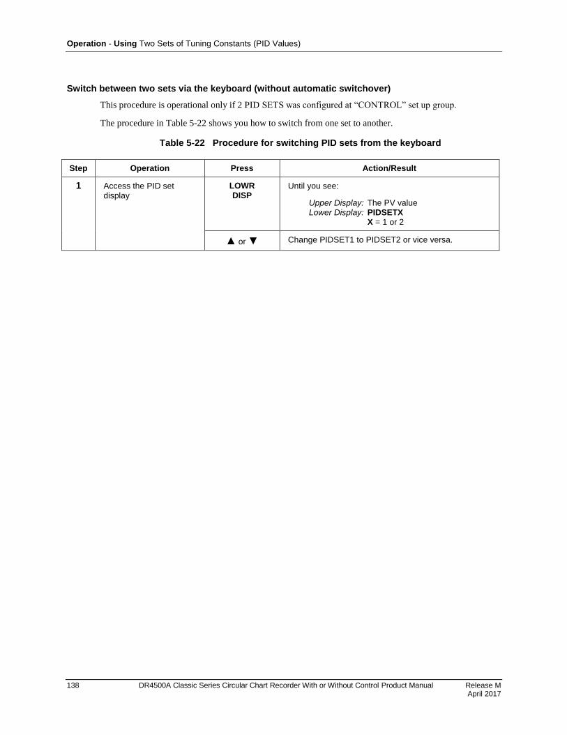
Operation - Using Two Sets of Tuning Constants (PID Values)
138 DR4500A Classic Series Circular Chart Recorder With or Without Control Product Manual Release M April 2017
Switch between two sets via the keyboard (without automatic switchover)
This procedure is operational only if 2 PID SETS was configured at “CONTROL” set up group.
The procedure in 80HTable 5-22 shows you how to switch from one set to another.
Table 5-22 Procedure for switching PID sets from the keyboard
Step Operation Press Action/Result
1 Access the PID set display
LOWR DISP
Until you see:
Upper Display: The PV value Lower Display: PIDSETX X = 1 or 2
or Change PIDSET1 to PIDSET2 or vice versa.
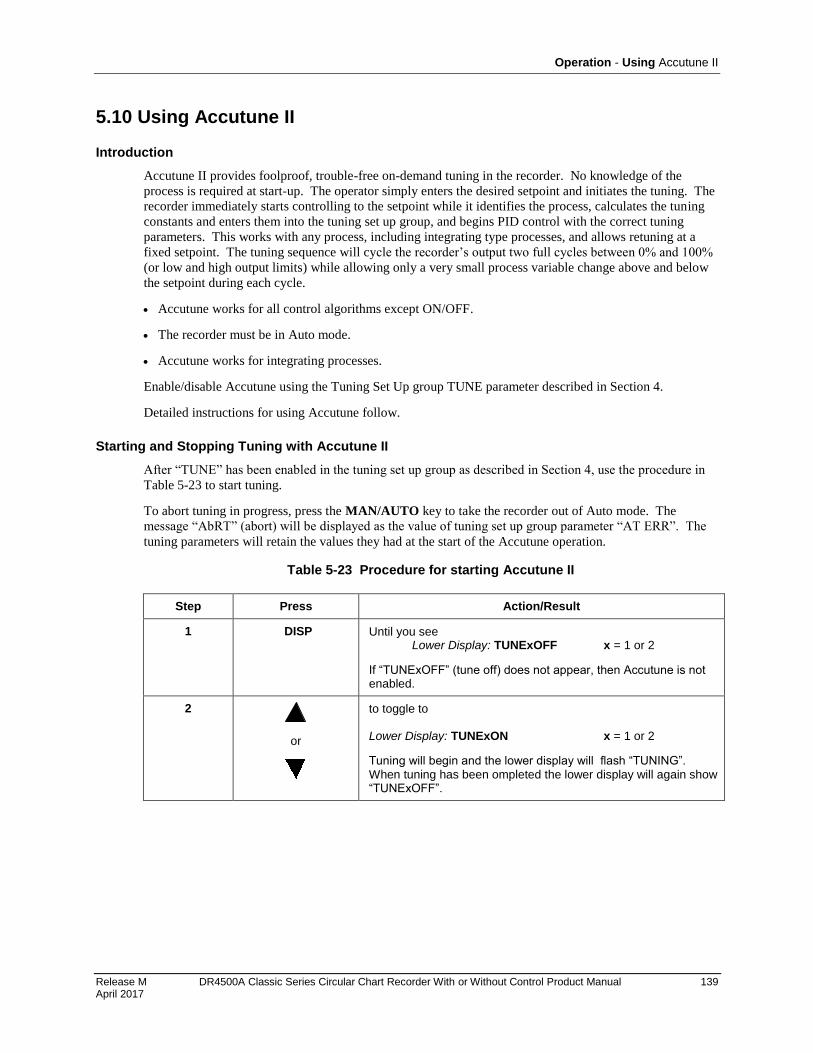
Operation - Using Accutune II
Release M DR4500A Classic Series Circular Chart Recorder With or Without Control Product Manual 139 April 2017
5.10 Using Accutune II
Introduction
Accutune II provides foolproof, trouble-free on-demand tuning in the recorder. No knowledge of the
process is required at start-up. The operator simply enters the desired setpoint and initiates the tuning. The
recorder immediately starts controlling to the setpoint while it identifies the process, calculates the tuning
constants and enters them into the tuning set up group, and begins PID control with the correct tuning
parameters. This works with any process, including integrating type processes, and allows retuning at a
fixed setpoint. The tuning sequence will cycle the recorder’s output two full cycles between 0% and 100%
(or low and high output limits) while allowing only a very small process variable change above and below
the setpoint during each cycle.
Accutune works for all control algorithms except ON/OFF.
The recorder must be in Auto mode.
Accutune works for integrating processes.
Enable/disable Accutune using the Tuning Set Up group TUNE parameter described in Section 4.
Detailed instructions for using Accutune follow.
Starting and Stopping Tuning with Accutune II
After “TUNE” has been enabled in the tuning set up group as described in Section 4, use the procedure in
81HTable 5-23 to start tuning.
To abort tuning in progress, press the MAN/AUTO key to take the recorder out of Auto mode. The
message “AbRT” (abort) will be displayed as the value of tuning set up group parameter “AT ERR”. The
tuning parameters will retain the values they had at the start of the Accutune operation.
Table 5-23 Procedure for starting Accutune II
Step Press Action/Result
1 DISP Until you see Lower Display: TUNExOFF x = 1 or 2
If “TUNExOFF” (tune off) does not appear, then Accutune is not enabled.
2
or
to toggle to Lower Display: TUNExON x = 1 or 2
Tuning will begin and the lower display will flash “TUNING”. When tuning has been ompleted the lower display will again show “TUNExOFF”.
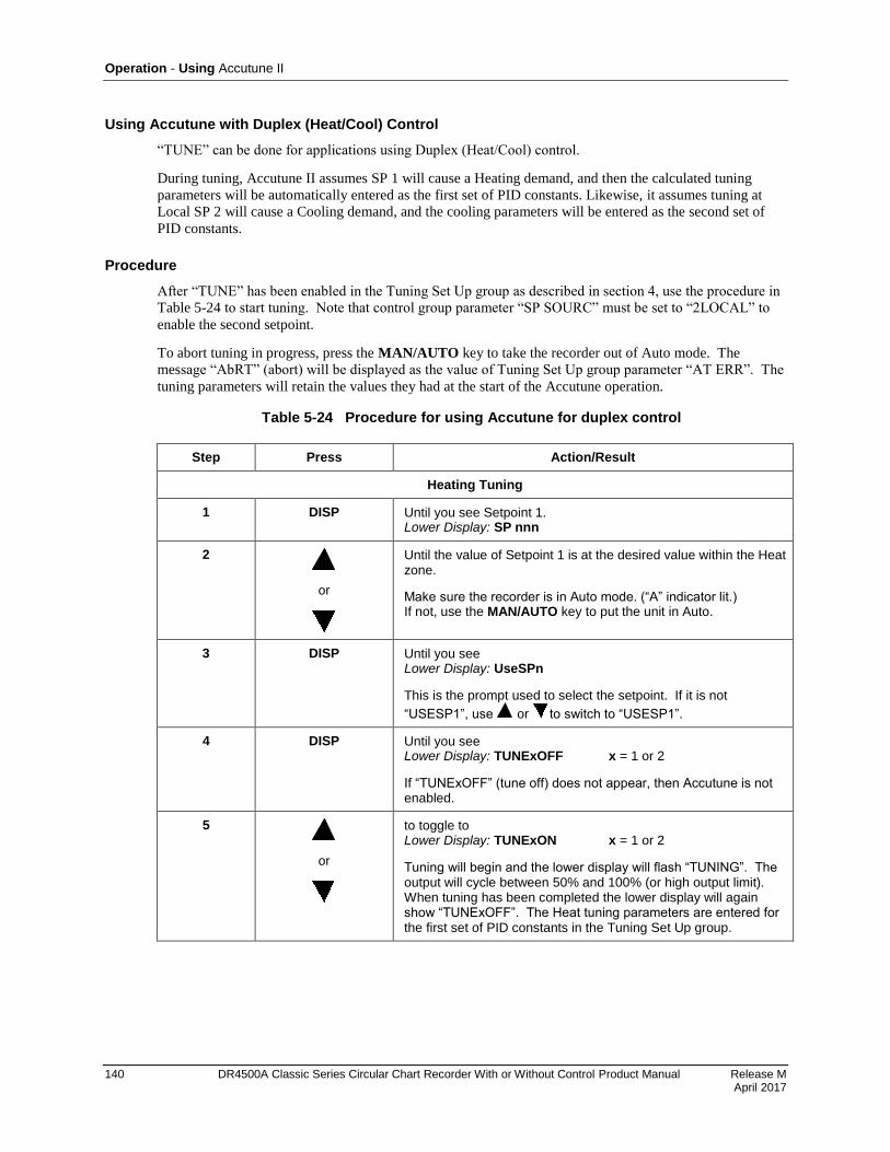
Operation - Using Accutune II
140 DR4500A Classic Series Circular Chart Recorder With or Without Control Product Manual Release M April 2017
Using Accutune with Duplex (Heat/Cool) Control
“TUNE” can be done for applications using Duplex (Heat/Cool) control.
During tuning, Accutune II assumes SP 1 will cause a Heating demand, and then the calculated tuning
parameters will be automatically entered as the first set of PID constants. Likewise, it assumes tuning at
Local SP 2 will cause a Cooling demand, and the cooling parameters will be entered as the second set of
PID constants.
Procedure
After “TUNE” has been enabled in the Tuning Set Up group as described in section 4, use the procedure in
82HTable 5-24 to start tuning. Note that control group parameter “SP SOURC” must be set to “2LOCAL” to
enable the second setpoint.
To abort tuning in progress, press the MAN/AUTO key to take the recorder out of Auto mode. The
message “AbRT” (abort) will be displayed as the value of Tuning Set Up group parameter “AT ERR”. The
tuning parameters will retain the values they had at the start of the Accutune operation.
Table 5-24 Procedure for using Accutune for duplex control
Step Press Action/Result
Heating Tuning
1 DISP Until you see Setpoint 1. Lower Display: SP nnn
2
or
Until the value of Setpoint 1 is at the desired value within the Heat zone.
Make sure the recorder is in Auto mode. (“A” indicator lit.) If not, use the MAN/AUTO key to put the unit in Auto.
3 DISP Until you see Lower Display: UseSPn
This is the prompt used to select the setpoint. If it is not
“USESP1”, use or to switch to “USESP1”.
4 DISP Until you see Lower Display: TUNExOFF x = 1 or 2
If “TUNExOFF” (tune off) does not appear, then Accutune is not enabled.
5
or
to toggle to Lower Display: TUNExON x = 1 or 2
Tuning will begin and the lower display will flash “TUNING”. The output will cycle between 50% and 100% (or high output limit). When tuning has been completed the lower display will again show “TUNExOFF”. The Heat tuning parameters are entered for the first set of PID constants in the Tuning Set Up group.
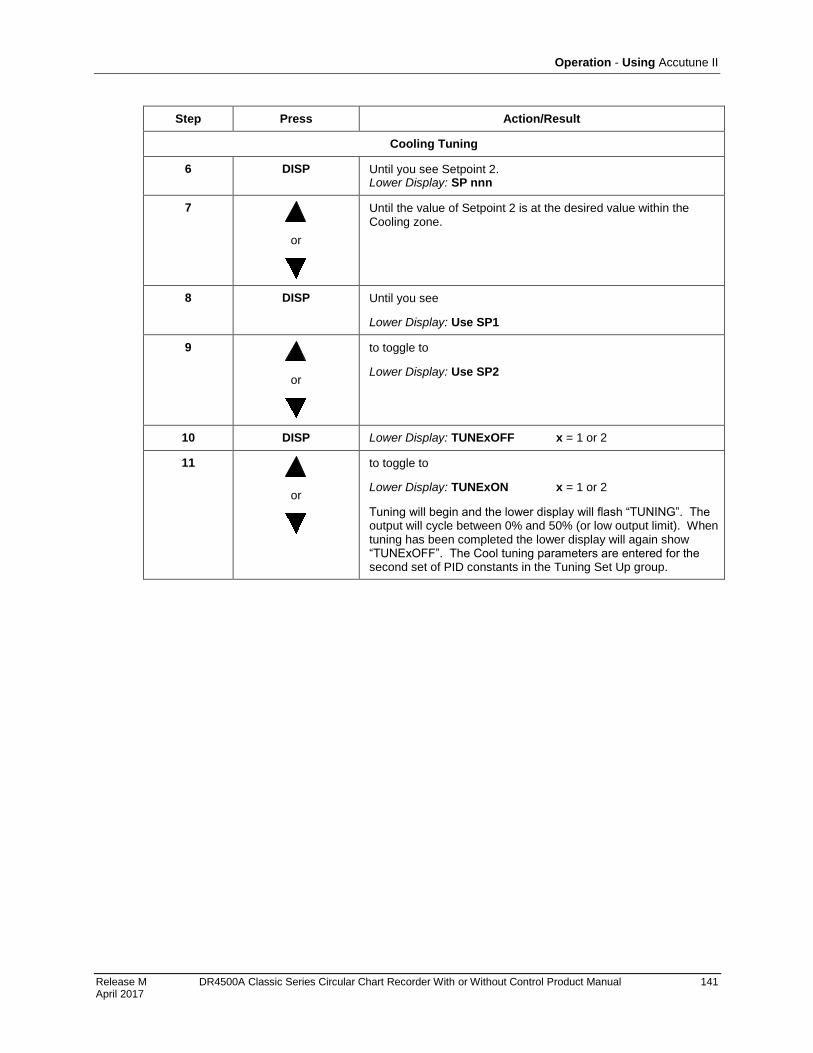
Operation - Using Accutune II
Release M DR4500A Classic Series Circular Chart Recorder With or Without Control Product Manual 141 April 2017
Step Press Action/Result
Cooling Tuning
6 DISP Until you see Setpoint 2. Lower Display: SP nnn
7
or
Until the value of Setpoint 2 is at the desired value within the Cooling zone.
8 DISP Until you see
Lower Display: Use SP1
9
or
to toggle to
Lower Display: Use SP2
10 DISP Lower Display: TUNExOFF x = 1 or 2
11
or
to toggle to
Lower Display: TUNExON x = 1 or 2
Tuning will begin and the lower display will flash “TUNING”. The output will cycle between 0% and 50% (or low output limit). When tuning has been completed the lower display will again show “TUNExOFF”. The Cool tuning parameters are entered for the second set of PID constants in the Tuning Set Up group.
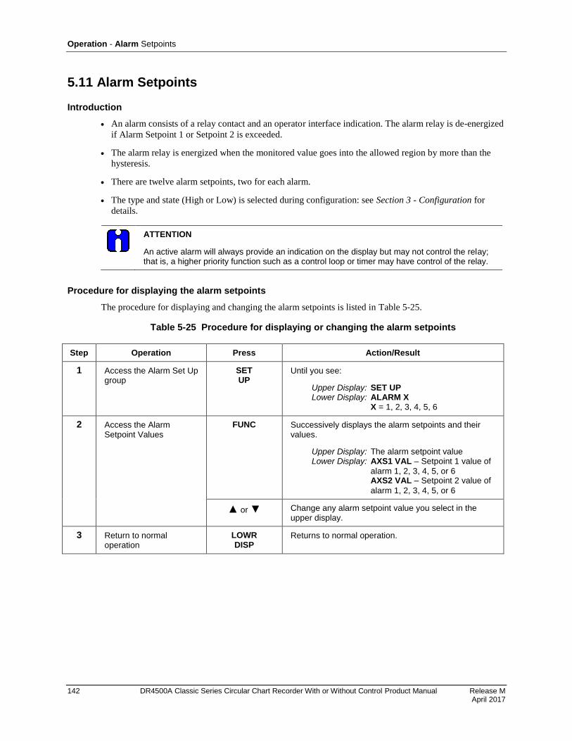
Operation - Alarm Setpoints
142 DR4500A Classic Series Circular Chart Recorder With or Without Control Product Manual Release M April 2017
5.11 Alarm Setpoints
Introduction
An alarm consists of a relay contact and an operator interface indication. The alarm relay is de-energized
if Alarm Setpoint 1 or Setpoint 2 is exceeded.
The alarm relay is energized when the monitored value goes into the allowed region by more than the
hysteresis.
There are twelve alarm setpoints, two for each alarm.
The type and state (High or Low) is selected during configuration: see Section 3 - Configuration for
details.
ATTENTION
An active alarm will always provide an indication on the display but may not control the relay; that is, a higher priority function such as a control loop or timer may have control of the relay.
Procedure for displaying the alarm setpoints
The procedure for displaying and changing the alarm setpoints is listed in 83HTable 5-25.
Table 5-25 Procedure for displaying or changing the alarm setpoints
Step Operation Press Action/Result
1 Access the Alarm Set Up group
SET UP
Until you see:
Upper Display: SET UP Lower Display: ALARM X X = 1, 2, 3, 4, 5, 6
2 Access the Alarm Setpoint Values
FUNC Successively displays the alarm setpoints and their values.
Upper Display: The alarm setpoint value Lower Display: AXS1 VAL – Setpoint 1 value of
alarm 1, 2, 3, 4, 5, or 6 AXS2 VAL – Setpoint 2 value of
alarm 1, 2, 3, 4, 5, or 6
or Change any alarm setpoint value you select in the upper display.
3 Return to normal operation
LOWR DISP
Returns to normal operation.
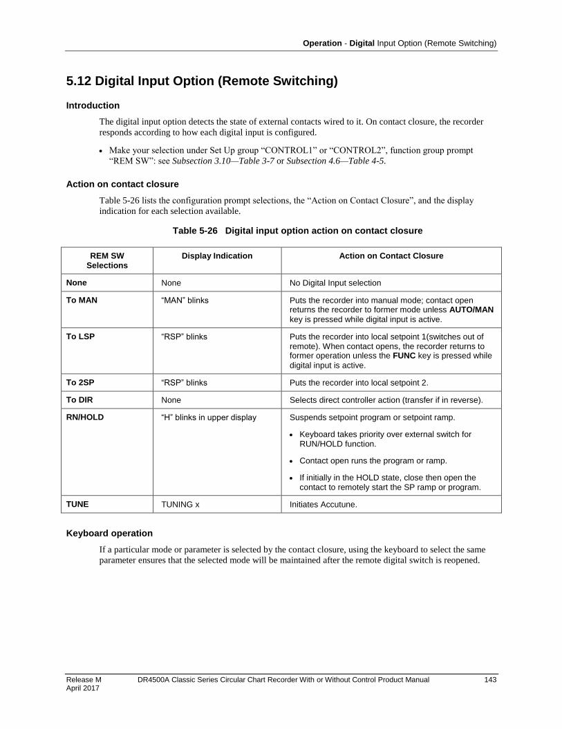
Operation - Digital Input Option (Remote Switching)
Release M DR4500A Classic Series Circular Chart Recorder With or Without Control Product Manual 143 April 2017
5.12 Digital Input Option (Remote Switching)
Introduction
The digital input option detects the state of external contacts wired to it. On contact closure, the recorder
responds according to how each digital input is configured.
Make your selection under Set Up group “CONTROL1” or “CONTROL2”, function group prompt
“REM SW”: see Subsection 3.10—Table 3-7 or Subsection 4.6—Table 4-5.
Action on contact closure
84HTable 5-26 lists the configuration prompt selections, the “Action on Contact Closure”, and the display
indication for each selection available.
Table 5-26 Digital input option action on contact closure
REM SW Selections
Display Indication Action on Contact Closure
None None No Digital Input selection
To MAN “MAN” blinks Puts the recorder into manual mode; contact open returns the recorder to former mode unless AUTO/MAN
key is pressed while digital input is active.
To LSP “RSP” blinks Puts the recorder into local setpoint 1(switches out of remote). When contact opens, the recorder returns to former operation unless the FUNC key is pressed while
digital input is active.
To 2SP “RSP” blinks Puts the recorder into local setpoint 2.
To DIR None Selects direct controller action (transfer if in reverse).
RN/HOLD “H” blinks in upper display Suspends setpoint program or setpoint ramp.
Keyboard takes priority over external switch for RUN/HOLD function.
Contact open runs the program or ramp.
If initially in the HOLD state, close then open the contact to remotely start the SP ramp or program.
TUNE TUNING x Initiates Accutune.
Keyboard operation
If a particular mode or parameter is selected by the contact closure, using the keyboard to select the same
parameter ensures that the selected mode will be maintained after the remote digital switch is reopened.
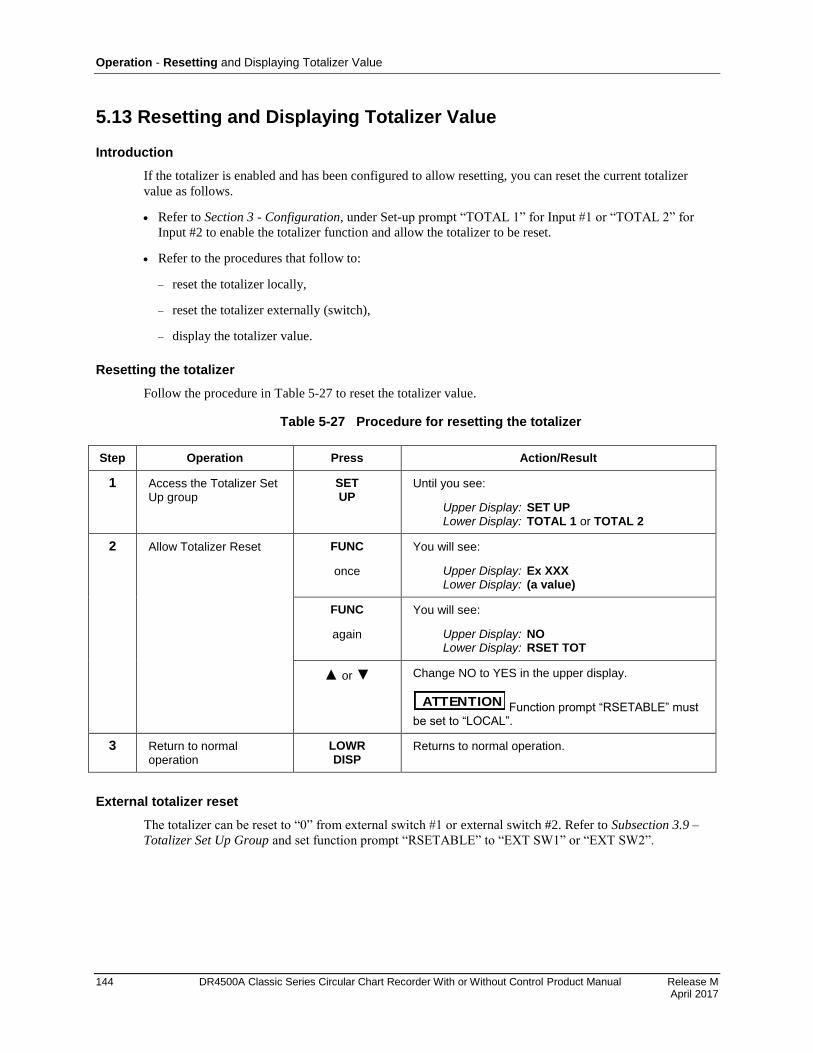
Operation - Resetting and Displaying Totalizer Value
144 DR4500A Classic Series Circular Chart Recorder With or Without Control Product Manual Release M April 2017
5.13 Resetting and Displaying Totalizer Value
Introduction
If the totalizer is enabled and has been configured to allow resetting, you can reset the current totalizer
value as follows.
Refer to Section 3 - Configuration, under Set-up prompt “TOTAL 1” for Input #1 or “TOTAL 2” for
Input #2 to enable the totalizer function and allow the totalizer to be reset.
Refer to the procedures that follow to:
reset the totalizer locally,
reset the totalizer externally (switch),
display the totalizer value.
Resetting the totalizer
Follow the procedure in 85HTable 5-27 to reset the totalizer value.
Table 5-27 Procedure for resetting the totalizer
Step Operation Press Action/Result
1 Access the Totalizer Set Up group
SET UP
Until you see:
Upper Display: SET UP Lower Display: TOTAL 1 or TOTAL 2
2 Allow Totalizer Reset FUNC
once
You will see:
Upper Display: Ex XXX Lower Display: (a value)
FUNC
again
You will see:
Upper Display: NO Lower Display: RSET TOT
or Change NO to YES in the upper display.
ATTENTION Function prompt “RSETABLE” must be set to “LOCAL”.
3 Return to normal operation
LOWR DISP
Returns to normal operation.
External totalizer reset
The totalizer can be reset to “0” from external switch #1 or external switch #2. Refer to Subsection 3.9 –
Totalizer Set Up Group and set function prompt “RSETABLE” to “EXT SW1” or “EXT SW2”.
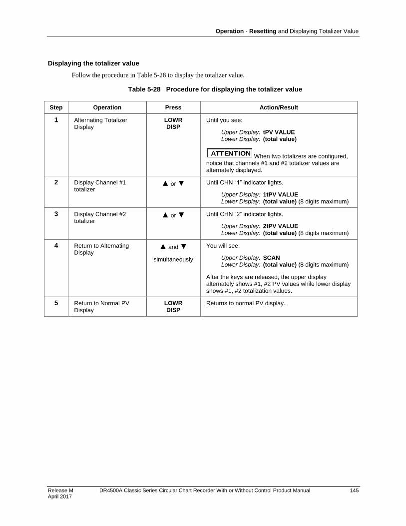
Operation - Resetting and Displaying Totalizer Value
Release M DR4500A Classic Series Circular Chart Recorder With or Without Control Product Manual 145 April 2017
Displaying the totalizer value
Follow the procedure in 86HTable 5-28 to display the totalizer value.
Table 5-28 Procedure for displaying the totalizer value
Step Operation Press Action/Result
1 Alternating Totalizer Display
LOWR DISP
Until you see:
Upper Display: tPV VALUE Lower Display: (total value)
ATTENTION When two totalizers are configured, notice that channels #1 and #2 totalizer values are alternately displayed.
2 Display Channel #1 totalizer
or Until CHN “1” indicator lights.
Upper Display: 1tPV VALUE Lower Display: (total value) (8 digits maximum)
3 Display Channel #2 totalizer
or Until CHN “2” indicator lights.
Upper Display: 2tPV VALUE Lower Display: (total value) (8 digits maximum)
4 Return to Alternating Display
and
simultaneously
You will see:
Upper Display: SCAN Lower Display: (total value) (8 digits maximum)
After the keys are released, the upper display alternately shows #1, #2 PV values while lower display shows #1, #2 totalization values.
5 Return to Normal PV Display
LOWR DISP
Returns to normal PV display.

Operation - Monitoring the External Event Operation
146 DR4500A Classic Series Circular Chart Recorder With or Without Control Product Manual Release M April 2017
5.14 Monitoring the External Event Operation
Event pen function
If Function prompt “PEN 1IN” under Set-up prompt “PEN 1” has been configured as DGTL1 or DGTL2,
the pen (channel) operates as an “event pen” and tracks the remote contact (switch) closure by way of the
digital 1 or digital 2 input wired to the alarm output/digital input printed circuit board.
Event pen operation
When the switch opens, the pen for the channel tracks at the configured OFF position (0-100%) on the
chart.
When the switch closes, the pen tracks at the configured ON position (0-100%) on the chart and tracks at
this position until the switch is opened.
Thus, the “Event Pen” record makes it easy to monitor the on/off operation of an external event.
5.15 Maximizing Pen Life
Steps for maximizing pen life
87HTable 5-29 lists nine steps that will help to maximize the life of your chart pen.
Table 5-29 Maximizing pen life
Step Action
1 Store the chart paper in a cool, clean dry place where the temperature does not exceed 40°C (104°F) and the humidity is below 65% RH.
2 Do not expose the pen tip and chart paper to abrasive chemicals or dust that cause excessive pen wear.
3 If the recorder is used in a dusty atmosphere, provide a positive ‘clean air purge’ to minimize dust particle accumulation on the chart paper.
4 Periodically clean the pen arm using a cotton swab dipped in alcohol. This is more important when the recorder is located in a dusty environment and no ‘clean air purge’ is used.
5 Never let the pen tip ride on the chart plate when the paper is not present. Use the pen lifter to raise the arm when changing the paper.
6 Keep the door closed while recording.
7 Always insert the pen arm tip into the shipping sponge when storing or shipping the recorder.
8 Be sure that the chart paper lays flat against the chart plate. Any ripple in the paper will cause light pen printing.
9 Be sure the chart hub assembly is pushed onto the motor shaft so that it is flush with the chart plate.
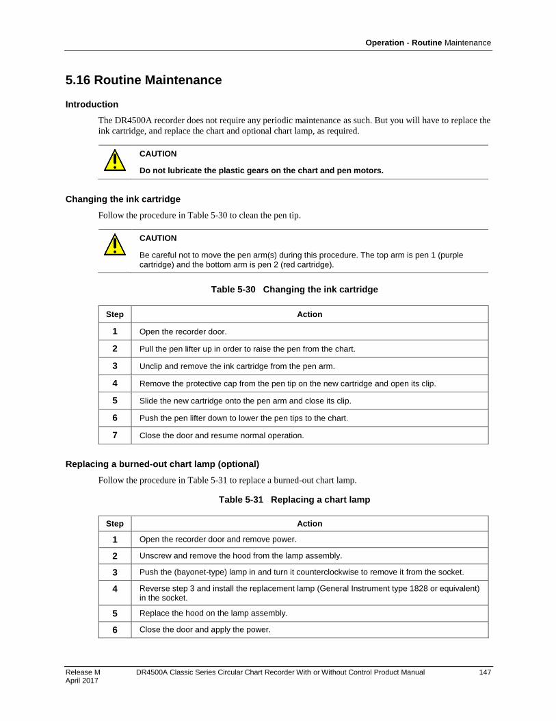
Operation - Routine Maintenance
Release M DR4500A Classic Series Circular Chart Recorder With or Without Control Product Manual 147 April 2017
5.16 Routine Maintenance
Introduction
The DR4500A recorder does not require any periodic maintenance as such. But you will have to replace the
ink cartridge, and replace the chart and optional chart lamp, as required.
CAUTION
Do not lubricate the plastic gears on the chart and pen motors.
Changing the ink cartridge
Follow the procedure in 88HTable 5-30 to clean the pen tip.
CAUTION
Be careful not to move the pen arm(s) during this procedure. The top arm is pen 1 (purple cartridge) and the bottom arm is pen 2 (red cartridge).
Table 5-30 Changing the ink cartridge
Step Action
1 Open the recorder door.
2 Pull the pen lifter up in order to raise the pen from the chart.
3 Unclip and remove the ink cartridge from the pen arm.
4 Remove the protective cap from the pen tip on the new cartridge and open its clip.
5 Slide the new cartridge onto the pen arm and close its clip.
6 Push the pen lifter down to lower the pen tips to the chart.
7 Close the door and resume normal operation.
Replacing a burned-out chart lamp (optional)
Follow the procedure in 89HTable 5-31 to replace a burned-out chart lamp.
Table 5-31 Replacing a chart lamp
Step Action
1 Open the recorder door and remove power.
2 Unscrew and remove the hood from the lamp assembly.
3 Push the (bayonet-type) lamp in and turn it counterclockwise to remove it from the socket.
4 Reverse step 3 and install the replacement lamp (General Instrument type 1828 or equivalent) in the socket.
5 Replace the hood on the lamp assembly.
6 Close the door and apply the power.

Operation - Installing/Replacing Chart
148 DR4500A Classic Series Circular Chart Recorder With or Without Control Product Manual Release M April 2017
5.17 Installing/Replacing Chart
Installing/replacing chart procedure
Follow the procedure in 90HTable 5-1 to install/replace the chart.
CAUTION
Store replacement charts in a dust-resistant location. Otherwise, accumulated dust on the chart may cause excessive pen tip abrasion which can shorten expected pen life. In addition, you may want to air purge the case if the recorder is mounted in an extremely dusty environment.
149
Release K DR4500A Classic Series Circular Chart Recorder With or Without Control Product Manual 149 May 2013
6. Setpoint Ramp/Soak Programming and Operation
6.1 Overview
Introduction
As an option, the recorder can support the programming of a 36-segment setpoint program containing 18
ramp segments and 18 soak segments. In a ramp segment the setpoint value is changed as specified during
configuration. The ramp is configured in terms of ramp time or ramp rate, depending on how you have
configured the RAMPUNIT parameter. During a soak segment the setpoint is held at the specified value.
For each control loop you can build up to 6 profiles using any number of consecutive segments of the
program.
Odd-numbered segments are always ramp segments. Even-numbered segments are always soaks. These
ramp and soak segments can be used in up to six programs. You designate the beginning and end segments
to determine where the program will start or stop.
Every profile must start with a ramp segment and end on a soak segment.
Control Loop must have Setpoint Source set to 1LOCAL.
Control Loop 1 uses SP RAMP1, Control Loop 2 uses SP RAMP2. SP RAMP1 and SP RAMP2 are the
prompts under which the setpoint program is configured.
Recorder must be set to use SP1 (setpoint 1).
Only contiguous segments can be used by a profile.
There can be overlap between programs. For example, Profile 1 could use Segments 1, 2, 3, 4, 5, and 6.
Profile 2 could be configured to begin with Segment 5 and end with Segment 8.
This section contains instructions for setting up a setpoint program, and for executing the program at
runtime.
Note that Section 4 contains instructions for using the setpoint ramp or setpoint rate. The SPRAMP
(setpoint ramp) and SPRATE (setpoint rate) parameters described in Section 4 must be set to
DISABL (disabled) if a setpoint program is to be used.
ATTENTION
If power is lost during execution of a program, upon power-up the recorder will use the last setpoint value prior to the beginning of the setpoint program. The program is placed in hold at the beginning. The Manual/Auto mode will be as configured under “POWER UP” in the “CONTROL” group.
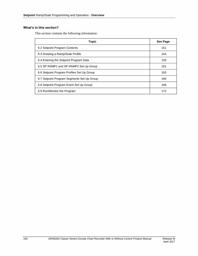
Setpoint Ramp/Soak Programming and Operation - Overview
150 DR4500A Classic Series Circular Chart Recorder With or Without Control Product Manual Release M April 2017
What’s in this section?
This section contains the following information:
Topic See Page
6.2 Setpoint Program Contents 151
6.3 Drawing a Ramp/Soak Profile 154
6.4 Entering the Setpoint Program Data 159
6.5 SP RAMP1 and SP RAMP2 Set Up Group 161
6.6 Setpoint Program Profiles Set Up Group 163
6.7 Setpoint Program Segments Set Up Group 165
6.8 Setpoint Program Event Set Up Group 168
6.9 Run/Monitor the Program 172

Setpoint Ramp/Soak Programming and Operation - Setpoint Program Contents
Release M DR4500A Classic Series Circular Chart Recorder With or Without Control Product Manual 151 April 2017
6.2 Setpoint Program Contents
What you will configure
You will configure all the data that is relevant to each ramp and soak segment for a given setpoint versus
time program (profile). The recorder will prompt you through the sequence of segments and associated
functions. These prompts and functions are described below.
Recycle number
The recycle number allows the program to recycle a specified number of times from beginning to end.
Range = 0 to 99
Guaranteed soak
A SOAK DEV (soak deviation) parameter is provided. If its value is not zero, then soaking will be frozen
for each segment until the difference (plus or minus) between PV and SP is less than or equal to the value
of SOAK DEV.
There are no guaranteed soaks whenever SOAKDEV = 0. In this case, soak segments start timing soak
duration as soon as the soak setpoint is first reached, regardless of where the process variable remains
relative to the soak setpoint during the duration of the segment.
The decimal location corresponds to input 1 decimal selection.
Profile number
The profile number specifies which of up to six profiles will run. Up to 6 profiles can be configured out of
any even number of consecutive segments from the 36 segments configured.
Program state
The program state selection determines the program state after completion.
The selections are:
DISABL = program is disabled
HOLD = program on hold
Recovery
If Recovery is enabled the setpoint program will continue from where it left off after the last power down.
Program End State
This determines the status of the recorder upon completion of the profile. The selections are:
LAST SP = hold at the last setpoint in the program
F SAFE = Manual mode, Failsafe Output

Setpoint Ramp/Soak Programming and Operation - Setpoint Program Contents
152 DR4500A Classic Series Circular Chart Recorder With or Without Control Product Manual Release M April 2017
Profile Start and Profile End
These selections let you specify the segments that will comprise each of the 6 profiles. The first segment
must be a ramp (odd-numbered segment) and the last segment must be a soak (even-numbered).
Ramp unit
The ramp unit selection determines the engineering units for the ramp segments.
The selections are:
TIME = Hours:Minutes
EU-H = Degrees/Hour OR EU-M = Degrees/Minute
Ramp time or rate segments
A ramp segment is used to change the setpoint to the next soak setpoint value in the program.
Ramps are odd-numbered segments. Segment 1 will be the initial ramp.
Ramps are specifed in terms of either:
TIME* - Hours:Minutes Range = 0-99 hrs:59 min.
or
EU-M* - Degrees/Minute Range = 0 to 999
EU-H* - Degrees/Hour
* The selection of time or rate is made at prompt “RAMP UNIT”
Set this prompt before entering any Ramp information.
ATTENTION
Entering “0” will imply an immediate step change in setpoint to the next soak.
Soak segments
A soak segment is a combination of soak setpoint (value) and a soak duration (time).
Soaks are even-numbered segments.
Segment 2 will be the initial soak value and soak time.
The soak setpoint range value must be within the setpoint high and low range limits in engineering units.
(Specify the setpoint range with SP HI and SP LO in the control group as described in Section 4.)
Soak time is the duration of the soak and is determined in:
TIME - Hours:Minutes Range = 0-99 hrs:59 min.
Segment Events
Each segment can be programmed to trigger an alarm which in turn deenergizes the associated relay. The
selected alarm must be programmed as an event type for this to occur. Selections are:
ALARM 1 – ALARM 6.

Setpoint Ramp/Soak Programming and Operation - Setpoint Program Contents
Release M DR4500A Classic Series Circular Chart Recorder With or Without Control Product Manual 153 April 2017
Segment events will not trigger a relay if that relay is configured with one of these higher priority
functions:
Control loop output
Interval timer
Alarm type other than “Event”.
See During alarm conditions an alarm will deenergize its associated relay unless a higher priority function
has been configured for that relay. See Table 3-11. If you want the alarm to control the relay, do not
configure a higher priority function.
Table 3-11.
Digital input (remote) operation
Program can be placed in RUN or HOLD state through a remote dry contact connected to optional digital
input terminals. The Control Loop parameters REM SW and REM SW2 parameters must be configured as
RN/HLD to support this function. The valid states of the contacts are:
RUN—contact closure places program in HOLD state
HOLD—contact open places program in RUN state
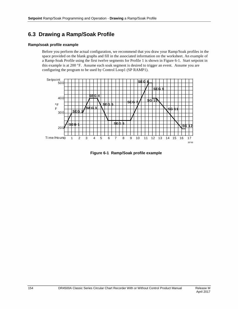
Setpoint Ramp/Soak Programming and Operation - Drawing a Ramp/Soak Profile
154 DR4500A Classic Series Circular Chart Recorder With or Without Control Product Manual Release M April 2017
6.3 Drawing a Ramp/Soak Profile
Ramp/soak profile example
Before you perform the actual configuration, we recommend that you draw your Ramp/Soak profiles in the
space provided on the blank graphs and fill in the associated information on the worksheet. An example of
a Ramp-Soak Profile using the first twelve segments for Profile 1 is shown in Figure 6-1. Start setpoint in
this example is at 200 F. Assume each soak segment is desired to trigger an event. Assume you are
configuring the program to be used by Control Loop1 (SP RAMP1).
500
400
200
300
°
F
Ti me/Hours0 1 2 3 4 5 6 7 8 9 10 11 12 13 14 15 16 17
SEG 2SEG 3
SEG 4
SEG 5
SEG 6
SEG 7
SEG 8
SEG 9
SG 10
SG 11
SG 12SEG 1
F
20765
Setpo int
Figure 6-1 Ramp/Soak profile example
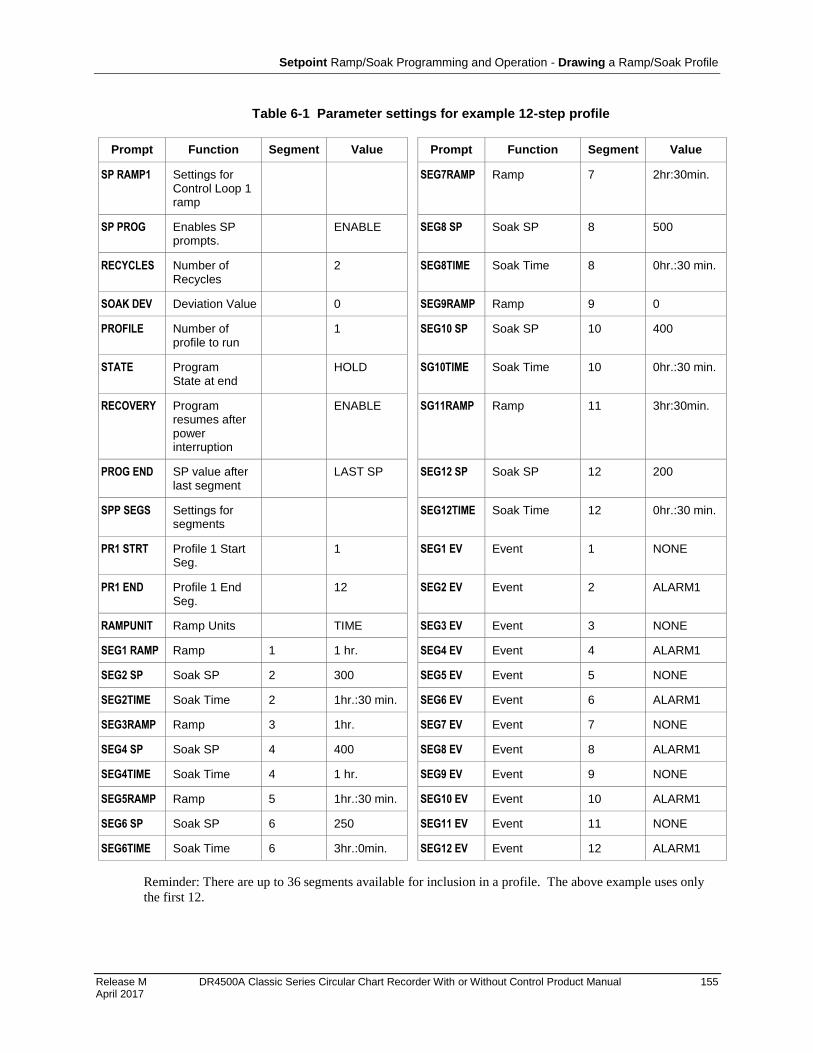
Setpoint Ramp/Soak Programming and Operation - Drawing a Ramp/Soak Profile
Release M DR4500A Classic Series Circular Chart Recorder With or Without Control Product Manual 155 April 2017
Table 6-1 Parameter settings for example 12-step profile
Prompt Function Segment Value Prompt Function Segment Value
SP RAMP1 Settings for Control Loop 1 ramp
SEG7RAMP Ramp 7 2hr:30min.
SP PROG Enables SP prompts.
ENABLE SEG8 SP Soak SP 8 500
RECYCLES Number of Recycles
2 SEG8TIME Soak Time 8 0hr.:30 min.
SOAK DEV Deviation Value 0 SEG9RAMP Ramp 9 0
PROFILE Number of profile to run
1 SEG10 SP Soak SP 10 400
STATE Program State at end
HOLD SG10TIME Soak Time 10 0hr.:30 min.
RECOVERY Program resumes after power interruption
ENABLE SG11RAMP Ramp 11 3hr:30min.
PROG END SP value after last segment
LAST SP SEG12 SP Soak SP 12 200
SPP SEGS Settings for segments
SEG12TIME Soak Time 12 0hr.:30 min.
PR1 STRT Profile 1 Start Seg.
1 SEG1 EV Event 1 NONE
PR1 END Profile 1 End Seg.
12 SEG2 EV Event 2 ALARM1
RAMPUNIT Ramp Units TIME SEG3 EV Event 3 NONE
SEG1 RAMP Ramp 1 1 hr. SEG4 EV Event 4 ALARM1
SEG2 SP Soak SP 2 300 SEG5 EV Event 5 NONE
SEG2TIME Soak Time 2 1hr.:30 min. SEG6 EV Event 6 ALARM1
SEG3RAMP Ramp 3 1hr. SEG7 EV Event 7 NONE
SEG4 SP Soak SP 4 400 SEG8 EV Event 8 ALARM1
SEG4TIME Soak Time 4 1 hr. SEG9 EV Event 9 NONE
SEG5RAMP Ramp 5 1hr.:30 min. SEG10 EV Event 10 ALARM1
SEG6 SP Soak SP 6 250 SEG11 EV Event 11 NONE
SEG6TIME Soak Time 6 3hr.:0min. SEG12 EV Event 12 ALARM1
Reminder: There are up to 36 segments available for inclusion in a profile. The above example uses only
the first 12.
Setpoint Ramp/Soak Programming and Operation - Drawing a Ramp/Soak Profile
156 DR4500A Classic Series Circular Chart Recorder With or Without Control Product Manual Release M April 2017
Profile graphs
Draw your six ramp/soak profiles on the graphs below and fill in the associated information in the
worksheets that follow in the next sections. This will give you a permanent record of your program and will
assist you when entering the ramp and soak values.
Profile 1
20766
Profile 2
20766
Setpoint Ramp/Soak Programming and Operation - Drawing a Ramp/Soak Profile
Release M DR4500A Classic Series Circular Chart Recorder With or Without Control Product Manual 157 April 2017
Profile 3
20766
Profile 4
20766
Setpoint Ramp/Soak Programming and Operation - Drawing a Ramp/Soak Profile
158 DR4500A Classic Series Circular Chart Recorder With or Without Control Product Manual Release M April 2017
Profile 5
20766
Profile 6
20766
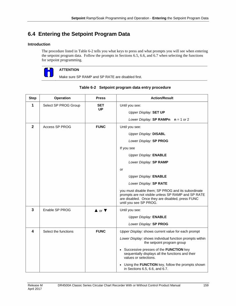
Setpoint Ramp/Soak Programming and Operation - Entering the Setpoint Program Data
Release M DR4500A Classic Series Circular Chart Recorder With or Without Control Product Manual 159 April 2017
6.4 Entering the Setpoint Program Data
Introduction
The procedure listed in Table 6-2 tells you what keys to press and what prompts you will see when entering
the setpoint program data. Follow the prompts in Sections 6.5, 6.6, and 6.7 when selecting the functions
for setpoint programming.
ATTENTION
Make sure SP RAMP and SP RATE are disabled first.
Table 6-2 Setpoint program data entry procedure
Step Operation Press Action/Result
1 Select SP PROG Group SET UP
Until you see:
Upper Display: SET UP
Lower Display: SP RAMPn n = 1 or 2
2 Access SP PROG FUNC Until you see:
Upper Display: DISABL
Lower Display: SP PROG
If you see
Upper Display: ENABLE
Lower Display: SP RAMP
or
Upper Display: ENABLE
Lower Display: SP RATE
you must disable them; SP PROG and its subordinate prompts are not visible unless SP RAMP and SP RATE are disabled. Once they are disabled, press FUNC until you see SP PROG.
3 Enable SP PROG or Until you see:
Upper Display: ENABLE
Lower Display: SP PROG
4 Select the functions FUNC Upper Display: shows current value for each prompt
Lower Display: shows individual function prompts within
the setpoint program group
Successive presses of the FUNCTION key
sequentially displays all the functions and their values or selections.
Using the FUNCTION key, follow the prompts shown
in Sections 6.5, 6.6, and 6.7.

Setpoint Ramp/Soak Programming and Operation - Entering the Setpoint Program Data
160 DR4500A Classic Series Circular Chart Recorder With or Without Control Product Manual Release M April 2017
Step Operation Press Action/Result
5 Change the value or selection of a function prompt
or This changes the value or selection in the upper display. If the display blinks, you are trying to select an unacceptable value.
6 Enter value or selection into memory
FUNC This enters the value or selection and goes to another prompt.
Repeat steps 4 and 5 for each function you want to change.
7 Exit configuration LOWR DISP
This exits from the configuration mode.
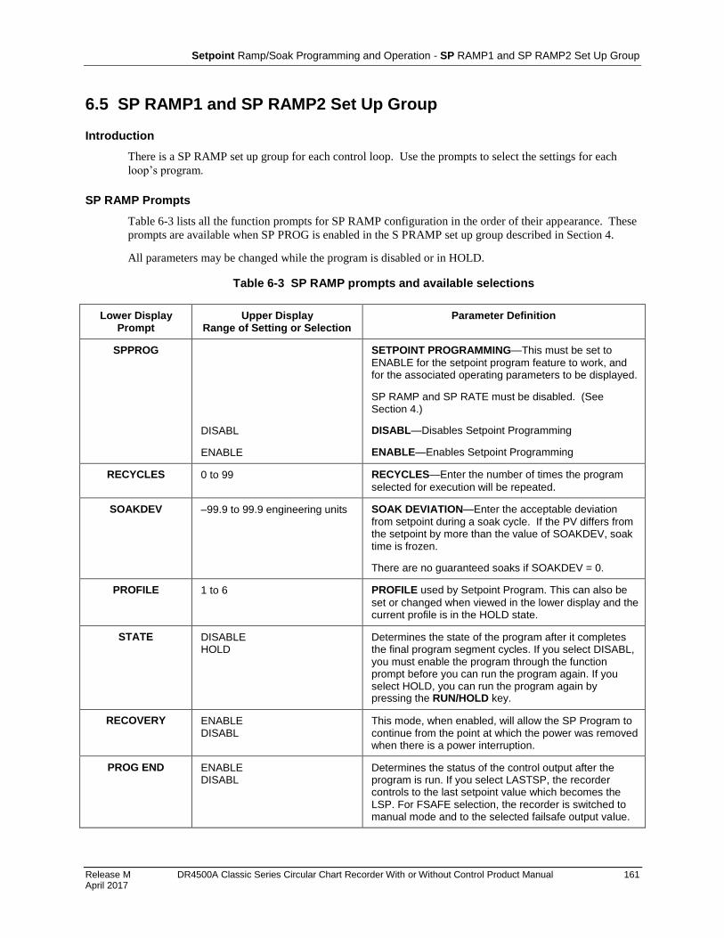
Setpoint Ramp/Soak Programming and Operation - SP RAMP1 and SP RAMP2 Set Up Group
Release M DR4500A Classic Series Circular Chart Recorder With or Without Control Product Manual 161 April 2017
6.5 SP RAMP1 and SP RAMP2 Set Up Group
Introduction
There is a SP RAMP set up group for each control loop. Use the prompts to select the settings for each
loop’s program.
SP RAMP Prompts
Table 6-3 lists all the function prompts for SP RAMP configuration in the order of their appearance. These
prompts are available when SP PROG is enabled in the S PRAMP set up group described in Section 4.
All parameters may be changed while the program is disabled or in HOLD.
Table 6-3 SP RAMP prompts and available selections
Lower Display Prompt
Upper Display Range of Setting or Selection
Parameter Definition
SPPROG
DISABL
ENABLE
SETPOINT PROGRAMMING—This must be set to
ENABLE for the setpoint program feature to work, and for the associated operating parameters to be displayed.
SP RAMP and SP RATE must be disabled. (See Section 4.)
DISABL—Disables Setpoint Programming
ENABLE—Enables Setpoint Programming
RECYCLES 0 to 99 RECYCLES—Enter the number of times the program
selected for execution will be repeated.
SOAKDEV –99.9 to 99.9 engineering units SOAK DEVIATION—Enter the acceptable deviation
from setpoint during a soak cycle. If the PV differs from the setpoint by more than the value of SOAKDEV, soak time is frozen.
There are no guaranteed soaks if SOAKDEV = 0.
PROFILE 1 to 6 PROFILE used by Setpoint Program. This can also be
set or changed when viewed in the lower display and the current profile is in the HOLD state.
STATE DISABLE HOLD
Determines the state of the program after it completes the final program segment cycles. If you select DISABL, you must enable the program through the function prompt before you can run the program again. If you select HOLD, you can run the program again by pressing the RUN/HOLD key.
RECOVERY ENABLE DISABL
This mode, when enabled, will allow the SP Program to continue from the point at which the power was removed when there is a power interruption.
PROG END ENABLE DISABL
Determines the status of the control output after the program is run. If you select LASTSP, the recorder controls to the last setpoint value which becomes the LSP. For FSAFE selection, the recorder is switched to manual mode and to the selected failsafe output value.

Setpoint Ramp/Soak Programming and Operation - SP RAMP1 and SP RAMP2 Set Up Group
162 DR4500A Classic Series Circular Chart Recorder With or Without Control Product Manual Release M April 2017
SP RAMP1 and SP RAMP2 worksheet
Use this worksheet to make a record of your SP RAMP1 and SP RAMP2 settings.
Prompt Description Range Your selection
SP RAMP1 Accesses prompts for Control Loop 1’s profile
N/A N/A
SP PROG Enables SP Program prompts. ENABLE DISABLE
ENABLE
RECYCLES Number of Recycles 0-99
SOAK DEV Deviation Value 0.0-99
PROFILE Number of profile to run 1-6
STATE Program State at end DISABL HOLD
RECOVERY Program resumes after power interruption
ENABLE DISABLE
PROG END SP value after last segment LASTSP FSAFE
SP RAMP2 Accesses prompts for Control Loop 2’s profile
N/A N/A
SP PROG Enables SP Program prompts. ENABLE DISABLE
ENABLE
RECYCLES Number of Recycles 0-99
SOAK DEV Deviation Value 0.0-99
PROFILE Number of profile to run 1-6
STATE Program State at end DISABL HOLD
RECOVERY Program resumes after power interruption
ENABLE DISABLE
PROG END SP value after last segment LASTSP FSAFE
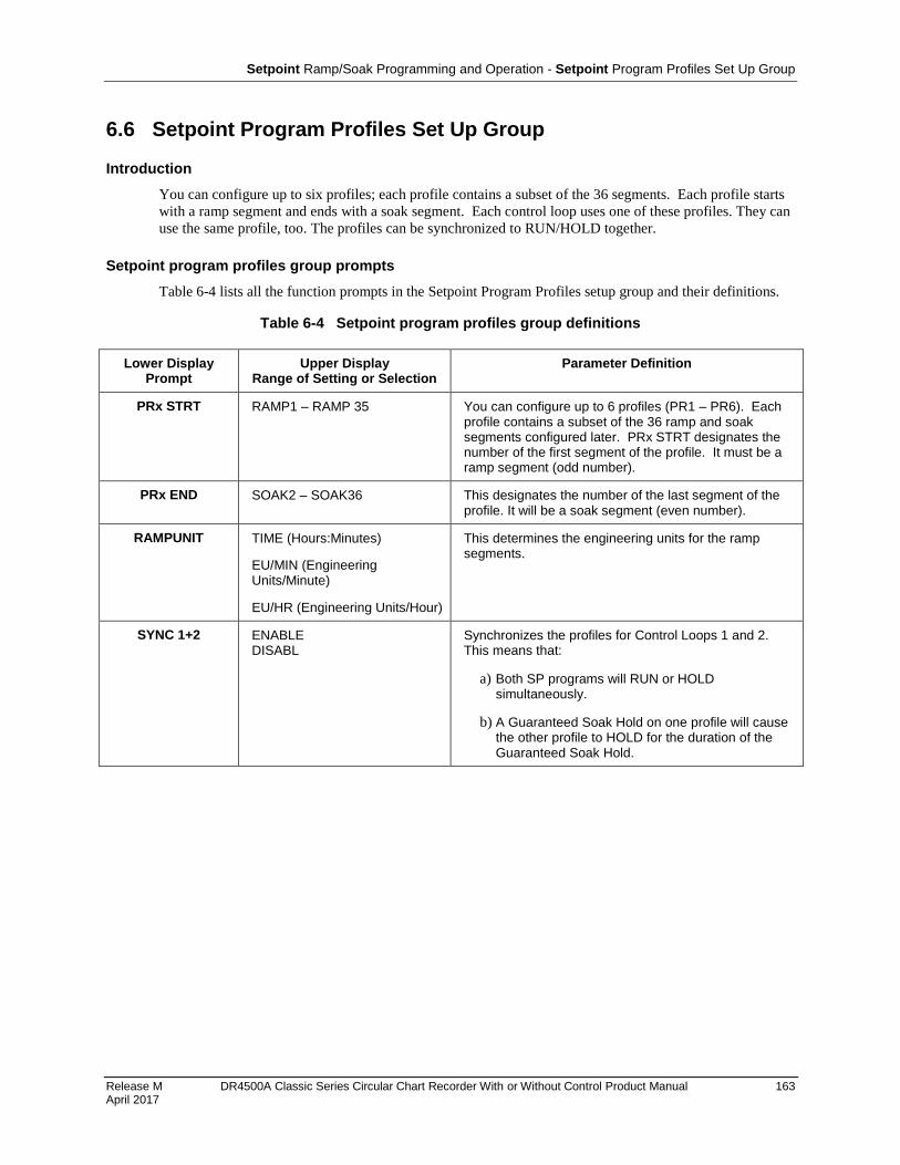
Setpoint Ramp/Soak Programming and Operation - Setpoint Program Profiles Set Up Group
Release M DR4500A Classic Series Circular Chart Recorder With or Without Control Product Manual 163 April 2017
6.6 Setpoint Program Profiles Set Up Group
Introduction
You can configure up to six profiles; each profile contains a subset of the 36 segments. Each profile starts
with a ramp segment and ends with a soak segment. Each control loop uses one of these profiles. They can
use the same profile, too. The profiles can be synchronized to RUN/HOLD together.
Setpoint program profiles group prompts
Table 6-4 lists all the function prompts in the Setpoint Program Profiles setup group and their definitions.
Table 6-4 Setpoint program profiles group definitions
Lower Display Prompt
Upper Display Range of Setting or Selection
Parameter Definition
PRx STRT RAMP1 – RAMP 35 You can configure up to 6 profiles (PR1 – PR6). Each profile contains a subset of the 36 ramp and soak segments configured later. PRx STRT designates the number of the first segment of the profile. It must be a ramp segment (odd number).
PRx END SOAK2 – SOAK36 This designates the number of the last segment of the profile. It will be a soak segment (even number).
RAMPUNIT TIME (Hours:Minutes)
EU/MIN (Engineering Units/Minute)
EU/HR (Engineering Units/Hour)
This determines the engineering units for the ramp segments.
SYNC 1+2 ENABLE DISABL
Synchronizes the profiles for Control Loops 1 and 2. This means that:
a) Both SP programs will RUN or HOLD simultaneously.
b) A Guaranteed Soak Hold on one profile will cause the other profile to HOLD for the duration of the Guaranteed Soak Hold.
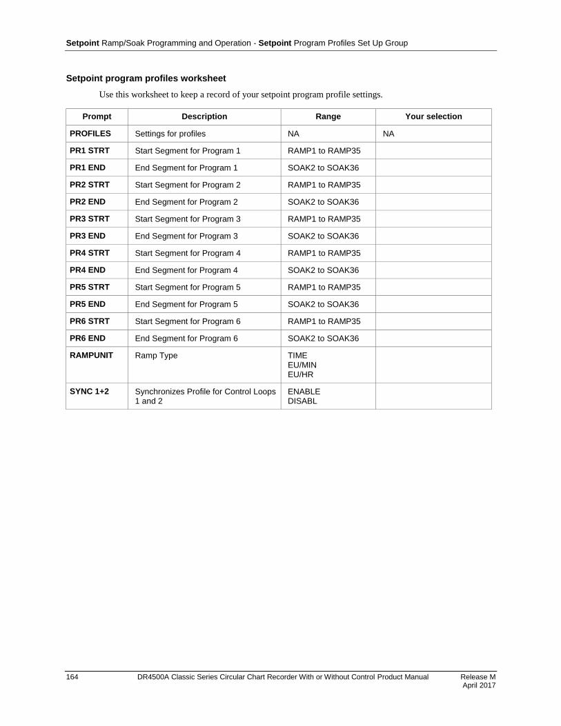
Setpoint Ramp/Soak Programming and Operation - Setpoint Program Profiles Set Up Group
164 DR4500A Classic Series Circular Chart Recorder With or Without Control Product Manual Release M April 2017
Setpoint program profiles worksheet
Use this worksheet to keep a record of your setpoint program profile settings.
Prompt Description Range Your selection
PROFILES Settings for profiles NA NA
PR1 STRT Start Segment for Program 1 RAMP1 to RAMP35
PR1 END End Segment for Program 1 SOAK2 to SOAK36
PR2 STRT Start Segment for Program 2 RAMP1 to RAMP35
PR2 END End Segment for Program 2 SOAK2 to SOAK36
PR3 STRT Start Segment for Program 3 RAMP1 to RAMP35
PR3 END End Segment for Program 3 SOAK2 to SOAK36
PR4 STRT Start Segment for Program 4 RAMP1 to RAMP35
PR4 END End Segment for Program 4 SOAK2 to SOAK36
PR5 STRT Start Segment for Program 5 RAMP1 to RAMP35
PR5 END End Segment for Program 5 SOAK2 to SOAK36
PR6 STRT Start Segment for Program 6 RAMP1 to RAMP35
PR6 END End Segment for Program 6 SOAK2 to SOAK36
RAMPUNIT Ramp Type TIME EU/MIN EU/HR
SYNC 1+2 Synchronizes Profile for Control Loops 1 and 2
ENABLE DISABL
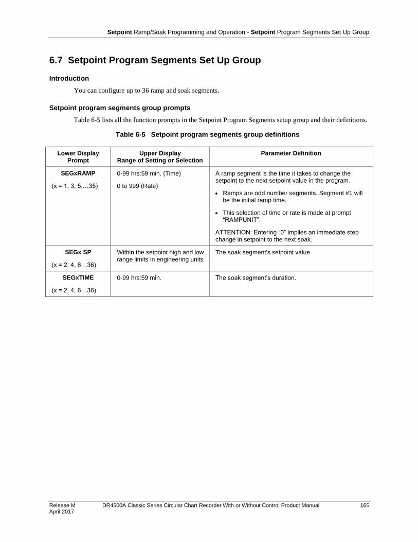
Setpoint Ramp/Soak Programming and Operation - Setpoint Program Segments Set Up Group
Release M DR4500A Classic Series Circular Chart Recorder With or Without Control Product Manual 165 April 2017
6.7 Setpoint Program Segments Set Up Group
Introduction
You can configure up to 36 ramp and soak segments.
Setpoint program segments group prompts
Table 6-5 lists all the function prompts in the Setpoint Program Segments setup group and their definitions.
Table 6-5 Setpoint program segments group definitions
Lower Display Prompt
Upper Display Range of Setting or Selection
Parameter Definition
SEGxRAMP
(x = 1, 3, 5,…35)
0-99 hrs:59 min. (Time)
0 to 999 (Rate)
A ramp segment is the time it takes to change the setpoint to the next setpoint value in the program.
Ramps are odd number segments. Segment #1 will be the initial ramp time.
This selection of time or rate is made at prompt “RAMPUNIT”.
ATTENTION: Entering “0” implies an immediate step change in setpoint to the next soak.
SEGx SP
(x = 2, 4, 6…36)
Within the setpoint high and low range limits in engineering units
The soak segment's setpoint value
SEGxTIME
(x = 2, 4, 6…36)
0-99 hrs:59 min. The soak segment’s duration.
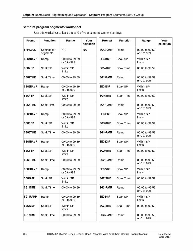
Setpoint Ramp/Soak Programming and Operation - Setpoint Program Segments Set Up Group
166 DR4500A Classic Series Circular Chart Recorder With or Without Control Product Manual Release M April 2017
Setpoint program segments worksheet
Use this worksheet to keep a record of your setpoint segment settings.
Prompt Function Range Your selection
Prompt Function Range Your selection
SPP SEGS Settings for segments
NA NA SG13RAMP Ramp 00.00 to 99.59 or 0 to 999
SEG1RAMP Ramp 00.00 to 99.59 or 0 to 999
SEG14SP Soak SP Within SP limits
SEG2 SP Soak SP Within SP limits
SG14TIME Soak Time 00.00 to 99.59
SEG2TIME Soak Time 00.00 to 99.59 SG15RAMP Ramp 00.00 to 99.59 or 0 to 999
SEG3RAMP Ramp 00.00 to 99.59 or 0 to 999
SEG16SP Soak SP Within SP limits
SEG4 SP Soak SP Within SP limits
SG16TIME Soak TIme 00.00 to 99.59
SEG4TIME Soak Time 00.00 to 99.59 SG17RAMP Ramp 00.00 to 99.59 or 0 to 999
SEG5RAMP Ramp 00.00 to 99.59 or 0 to 999
SEG18SP Soak SP Within SP limits
SEG6 SP Soak SP Within SP limits
SG18TIME Soak TIme 00.00 to 99.59
SEG6TIME Soak TIme 00.00 to 99.59 SG19RAMP Ramp 00.00 to 99.59 or 0 to 999
SEG7RAMP Ramp 00.00 to 99.59 or 0 to 999
SEG20SP Soak SP Within SP limits
SEG8 SP Soak SP Within SP limits
SG20TIME Soak TIme 00.00 to 99.59
SEG8TIME Soak TIme 00.00 to 99.59 SG21RAMP Ramp 00.00 to 99.59 or 0 to 999
SEG9RAMP Ramp 00.00 to 99.59 or 0 to 999
SEG22SP Soak SP Within SP limits
SEG10SP Soak SP Within SP limits
SG22TIME Soak TIme 00.00 to 99.59
SG10TIME Soak TIme 00.00 to 99.59 SG23RAMP Ramp 00.00 to 99.59 or 0 to 999
SG11RAMP Ramp 00.00 to 99.59 or 0 to 999
SEG24SP Soak SP Within SP limits
SEG12SP Soak SP Within SP limits
SG24TIME Soak Time 00.00 to 99.59
SG12TIME Soak TIme 00.00 to 99.59 SG25RAMP Ramp 00.00 to 99.59 or 0 to 999

Setpoint Ramp/Soak Programming and Operation - Setpoint Program Segments Set Up Group
Release M DR4500A Classic Series Circular Chart Recorder With or Without Control Product Manual 167 April 2017
Prompt Function Range Your selection
Prompt Function Range Your selection
SEG26SP Soak SP Within SP limits
SG31RAMP Ramp 00.00 to 99.59 or 0 to 999
SG26TIME Soak Time 00.00 to 99.59 SEG32SP Soak SP Within SP limits
SG27RAMP Ramp 00.00 to 99.59 or 0 to 999
SG32TIME Soak Time 00.00 to 99.59
SEG28SP Soak SP Within SP limits
SG33RAMP Ramp 00.00 to 99.59 or 0 to 999
SG28TIME Soak Time 00.00 to 99.59 SEG34SP Soak SP Within SP limits
SG29RAMP Ramp 00.00 to 99.59 or 0 to 999
SG34TIME Soak Time 00.00 to 99.59
SEG30SP Soak SP Within SP limits
SG35RAMP Ramp 00.00 to 99.59 or 0 to 999
SG30TIME Soak Time 00.00 to 99.59 SEG36SP Soak SP Within SP limits
SG36TIME Soak Time 00.00 to 99.59
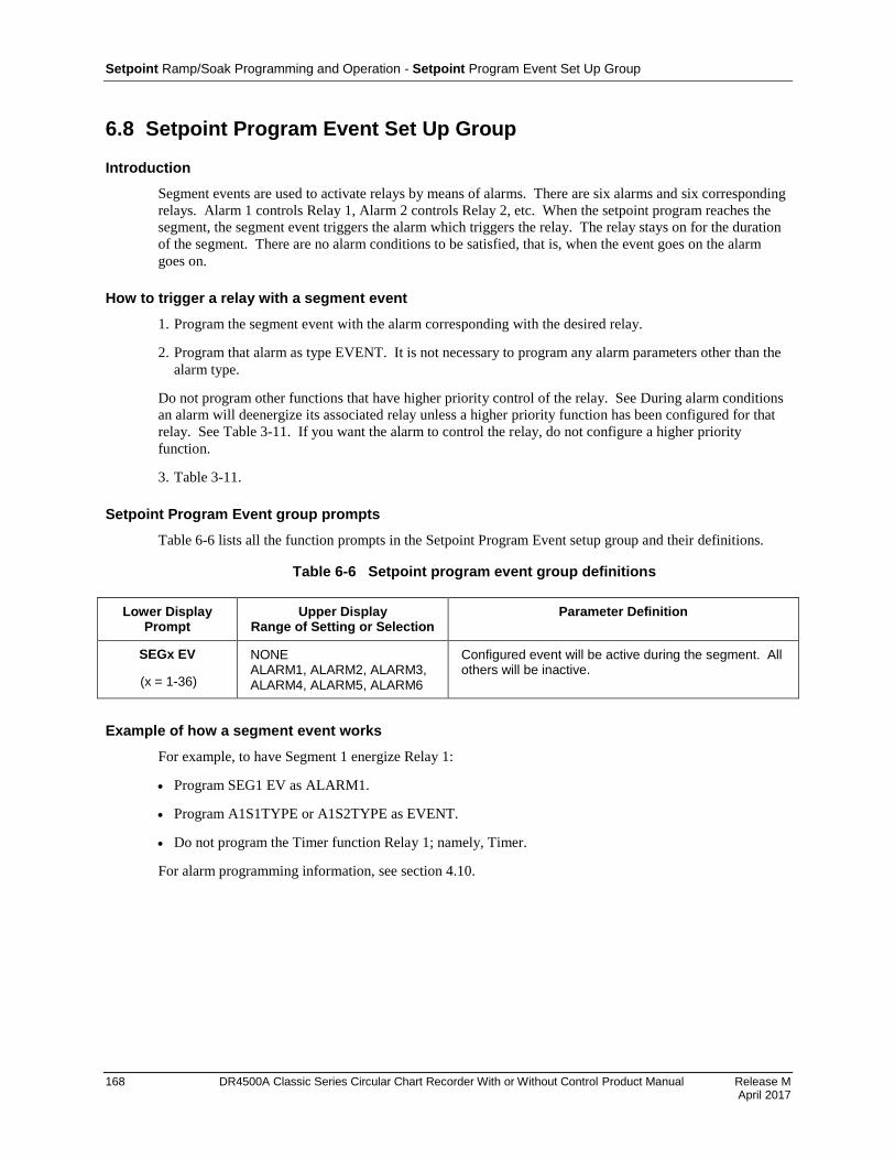
Setpoint Ramp/Soak Programming and Operation - Setpoint Program Event Set Up Group
168 DR4500A Classic Series Circular Chart Recorder With or Without Control Product Manual Release M April 2017
6.8 Setpoint Program Event Set Up Group
Introduction
Segment events are used to activate relays by means of alarms. There are six alarms and six corresponding
relays. Alarm 1 controls Relay 1, Alarm 2 controls Relay 2, etc. When the setpoint program reaches the
segment, the segment event triggers the alarm which triggers the relay. The relay stays on for the duration
of the segment. There are no alarm conditions to be satisfied, that is, when the event goes on the alarm
goes on.
How to trigger a relay with a segment event
1. Program the segment event with the alarm corresponding with the desired relay.
2. Program that alarm as type EVENT. It is not necessary to program any alarm parameters other than the
alarm type.
Do not program other functions that have higher priority control of the relay. See During alarm conditions
an alarm will deenergize its associated relay unless a higher priority function has been configured for that
relay. See Table 3-11. If you want the alarm to control the relay, do not configure a higher priority
function.
3. Table 3-11.
Setpoint Program Event group prompts
Table 6-6 lists all the function prompts in the Setpoint Program Event setup group and their definitions.
Table 6-6 Setpoint program event group definitions
Lower Display Prompt
Upper Display Range of Setting or Selection
Parameter Definition
SEGx EV
(x = 1-36)
NONE ALARM1, ALARM2, ALARM3, ALARM4, ALARM5, ALARM6
Configured event will be active during the segment. All others will be inactive.
Example of how a segment event works
For example, to have Segment 1 energize Relay 1:
Program SEG1 EV as ALARM1.
Program A1S1TYPE or A1S2TYPE as EVENT.
Do not program the Timer function Relay 1; namely, Timer.
For alarm programming information, see section 4.10.
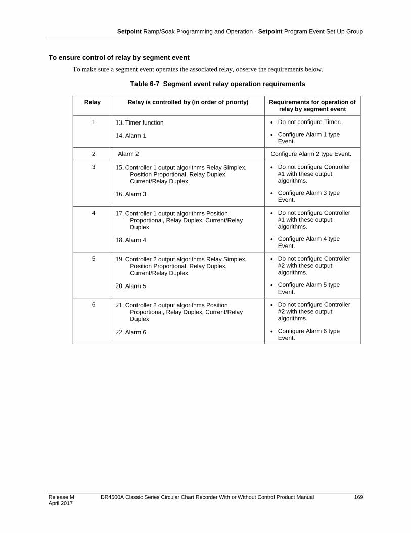
Setpoint Ramp/Soak Programming and Operation - Setpoint Program Event Set Up Group
Release M DR4500A Classic Series Circular Chart Recorder With or Without Control Product Manual 169 April 2017
To ensure control of relay by segment event
To make sure a segment event operates the associated relay, observe the requirements below.
Table 6-7 Segment event relay operation requirements
Relay Relay is controlled by (in order of priority) Requirements for operation of relay by segment event
1 13. Timer function
14. Alarm 1
Do not configure Timer.
Configure Alarm 1 type Event.
2 Alarm 2 Configure Alarm 2 type Event.
3 15. Controller 1 output algorithms Relay Simplex, Position Proportional, Relay Duplex, Current/Relay Duplex
16. Alarm 3
Do not configure Controller #1 with these output algorithms.
Configure Alarm 3 type Event.
4 17. Controller 1 output algorithms Position Proportional, Relay Duplex, Current/Relay Duplex
18. Alarm 4
Do not configure Controller #1 with these output algorithms.
Configure Alarm 4 type Event.
5 19. Controller 2 output algorithms Relay Simplex, Position Proportional, Relay Duplex, Current/Relay Duplex
20. Alarm 5
Do not configure Controller #2 with these output algorithms.
Configure Alarm 5 type Event.
6 21. Controller 2 output algorithms Position Proportional, Relay Duplex, Current/Relay Duplex
22. Alarm 6
Do not configure Controller #2 with these output algorithms.
Configure Alarm 6 type Event.

Setpoint Ramp/Soak Programming and Operation - Setpoint Program Event Set Up Group
170 DR4500A Classic Series Circular Chart Recorder With or Without Control Product Manual Release M April 2017
Setpoint program event worksheet
Use this worksheet to make a record of the segment event settings.
Prompt Description Range Your selection
SPP EVNT Access to events N/A N/A
SEG1 EV Event status NONE ALARM1 ALARM2 ALARM3 ALARM4 ALARM5 ALARM6
SEG2 EV Event status Same
SEG3 EV Event status Same
SEG4 EV Event status Same
SEG5 EV Event status Same
SEG6 EV Event status Same
SEG7 EV Event status Same
SEG8 EV Event status Same
SEG9 EV Event status Same
SEG10 EV Event status Same
SEG11 EV Event status Same
SEG12 EV Event status Same
SEG13 EV Event status Same
SEG14 EV Event status Same
SEG15 EV Event status Same
SEG16 EV Event status Same
SEG17 EV Event status Same
SEG18 EV Event status Same
SEG19 EV Event status Same
SEG20 EV Event status Same
SEG21 EV Event status Same
SEG22 EV Event status Same
SEG23 EV Event status Same
SEG24 EV Event status Same
SEG25 EV Event status Same
SEG26 EV Event status Same
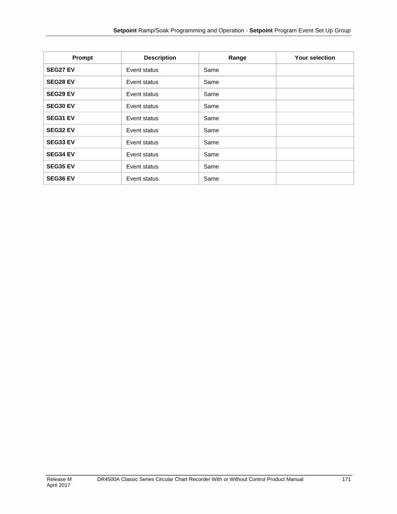
Setpoint Ramp/Soak Programming and Operation - Setpoint Program Event Set Up Group
Release M DR4500A Classic Series Circular Chart Recorder With or Without Control Product Manual 171 April 2017
Prompt Description Range Your selection
SEG27 EV Event status Same
SEG28 EV Event status Same
SEG29 EV Event status Same
SEG30 EV Event status Same
SEG31 EV Event status Same
SEG32 EV Event status Same
SEG33 EV Event status Same
SEG34 EV Event status Same
SEG35 EV Event status Same
SEG36 EV Event status Same

Setpoint Ramp/Soak Programming and Operation - Run/Monitor the Program
172 DR4500A Classic Series Circular Chart Recorder With or Without Control Product Manual Release M April 2017
6.9 Run/Monitor the Program
Introduction
Make sure all the “SP PROG” function prompts under the Set Up group “SP RAMP” have been configured
with the required data.
An “H” appears in the upper display indicating that the program is in the HOLD state. If an “H” does not
appear, go to the SP Program configuration procedure and enable the program instead of disabling.
ATTENTION
For recorders with two controllers (both enabled), remember that any controller-related values displayed correspond with the lighted CHN indicator. “1” means that the values apply for Controller #1 and “2” means that the values apply for Controller #2.
Run/Monitor functions
Table 6-8 lists all the functions required to run and monitor the program.
Table 6-8 Run/Monitor functions
Function Press Result
Run State RUN HOLD
Initiates the setpoint program.
“H” changes to “R” in the upper display indicating that the
program is running. PV value and pen trace tracks the ramp soak profile.
Hold State RUN HOLD
Holds the setpoint program.
An “H” appears in the upper display indicating that the
program is in the HOLD state.
The setpoint holds at the current setpoint. Press again to continue to run.
External Hold If Remote Switching (Digital Input Option) is present on your recorder, contact closure places the recorder in the HOLD state, if the setpoint program is running.
The “H” in the upper display blinks.
ATTENTION The keyboard takes priority over external switch for the RUN/HOLD function.
Contact reopening runs program.
Guaranteed Soak If a non-zero value has been entered for SOAK DEV, a Soak Segment will be suspended until deviation (SP–PV) is less than SOAK DEV.
A "G" will appear in the upper display during Soak
Deviation Hold.

Setpoint Ramp/Soak Programming and Operation - Run/Monitor the Program
Release M DR4500A Classic Series Circular Chart Recorder With or Without Control Product Manual 173 April 2017
Function Press Result
Viewing the present ramp or soak segment number and time
LOWR DISP
Until you see:
Upper Display: R and the PV value
Lower Display:
For Ramp segments:
# RA XX.XX
Segment Number (odd only)
Indicates Ramp segment
Ramp Time - Hours:Minutes or
Ramp Rate - Degrees/M inute
For Soak segments:
# SK XX.XX
Segment Number (even only)
Indicates Soak segment
Time remaining in segment in
Hrs:Minutes including current
partially completed minute
Skipping segments LOWR DISP
Until you see:
Upper Display: R and the PV value
Lower Display: #RA XX.XX (Ramp Segment) #SK XX.XX (Soak Segment)
RUN HOLD
To hold the SP Program
An “H” appears in the upper display indicating that the
program is in the HOLD state.
or To select new segment
RUN HOLD
or
LOWR DISP
To begin running at new segment
To retain the old segment
Viewing the number of cycles left in the program
LOWER DISP
Until you see:
Upper Display: R and the PV value
Lower Display: RECYC XX
Remaining cycles 0 to 99 This number includes the current partially completed cycle.
End Program When the final segment is completed, the “R” in the upper display either changes to “H” if configured for HOLD state,
or disappears if configured for DISABL of setpoint programming.
The recorder operates at the last setpoint in the program in automatic or will be in manual mode at the failsafe output.

Setpoint Ramp/Soak Programming and Operation - Run/Monitor the Program
174 DR4500A Classic Series Circular Chart Recorder With or Without Control Product Manual Release M April 2017
This page has been intentionally left blank
175
Release K DR4500A Classic Series Circular Chart Recorder With or Without Control Product Manual 175 May 2013
7. Input Calibration
7.1 Overview
SHOCK HAZARD—WARNING! Disregard of these instructions may cause injury or death.
INPUT CALIBRATION MAY REQUIRE ACCESS TO HAZARDOUS LIVE CIRCUITS, AND SHOULD ONLY BE PERFORMED BY QUALIFIED SERVICE PERSONNEL. MORE THAN ONE SWITCH MAY BE REQUIRED TO DE-ENERGIZE UNIT BEFORE CALIBRATION.
Introduction
This section describes the field calibration procedures for inputs 1 and 2. All DR4500A recorders are
factory calibrated prior to shipment. It should not, therefore, be necessary to recalibrate the recorder when it
is initially installed. However, you must recalibrate the input if any one of the conditions summarized
below applies:
The thermocouple or RTD input must meet published* accuracy rates. Note that the factory calibration
at reference is ±1.2°F plus ±10 microvolts for thermocouples or ±0.3 ohms for RTDs.
* Specifications 44-45-03-15
You are using a 0–10 Vdc input. Recalibration is necessary because the resistor network used for this
input has a tolerance of ±1.0%.
You have cause to believe that the recorder is out of calibration.
You must perform regularly scheduled or periodic recalibration based on your own needs.
You have performed specific servicing activities such as replacement of an input PCB.
ATTENTION
Replacing a main PCB does not normally require recalibration since a new main PCB is already factory calibrated, whereas an input PCB is not.
You have changed the input type through configuration which results in the loss of the previous field
calibration, but restores factory calibration. See subsection 7.2 Restoring Factory Calibration paragraph
that follows.
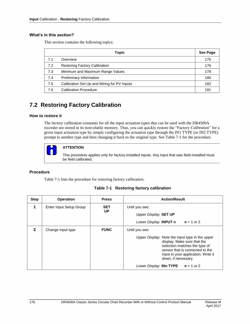
Input Calibration - Restoring Factory Calibration
176 DR4500A Classic Series Circular Chart Recorder With or Without Control Product Manual Release M April 2017
What’s in this section?
This section contains the following topics:
Topic See Page
7.1 Overview 175
7.2 Restoring Factory Calibration 176
7.3 Minimum and Maximum Range Values 178
7.4 Preliminary Information 180
7.5 Calibration Set Up and Wiring for PV Inputs 182
7.6 Calibration Procedure 191
7.2 Restoring Factory Calibration
How to restore it
The factory calibration constants for all the input actuation types that can be used with the DR4500A
recorder are stored in its nonvolatile memory. Thus, you can quickly restore the “Factory Calibration” for a
given input actuation type by simply configuring the actuation type through the IN1 TYPE (or IN2 TYPE)
prompt to another type and then changing it back to the original type. See Table 7-1 for the procedure.
ATTENTION
This procedure applies only for factory-installed inputs. Any input that was field-installed must be field calibrated.
Procedure
Table 7-1 lists the procedure for restoring factory calibration.
Table 7-1 Restoring factory calibration
Step Operation Press Action/Result
1 Enter Input Setup Group SET UP
Until you see:
Upper Display: SET UP
Lower Display: INPUT n n = 1 or 2
2 Change input type FUNC Until you see:
Upper Display: Note the input type in the upper display. Make sure that the selection matches the type of sensor that is connected to the input in your application. Write it down, if necessary.
Lower Display: INn TYPE n = 1 or 2
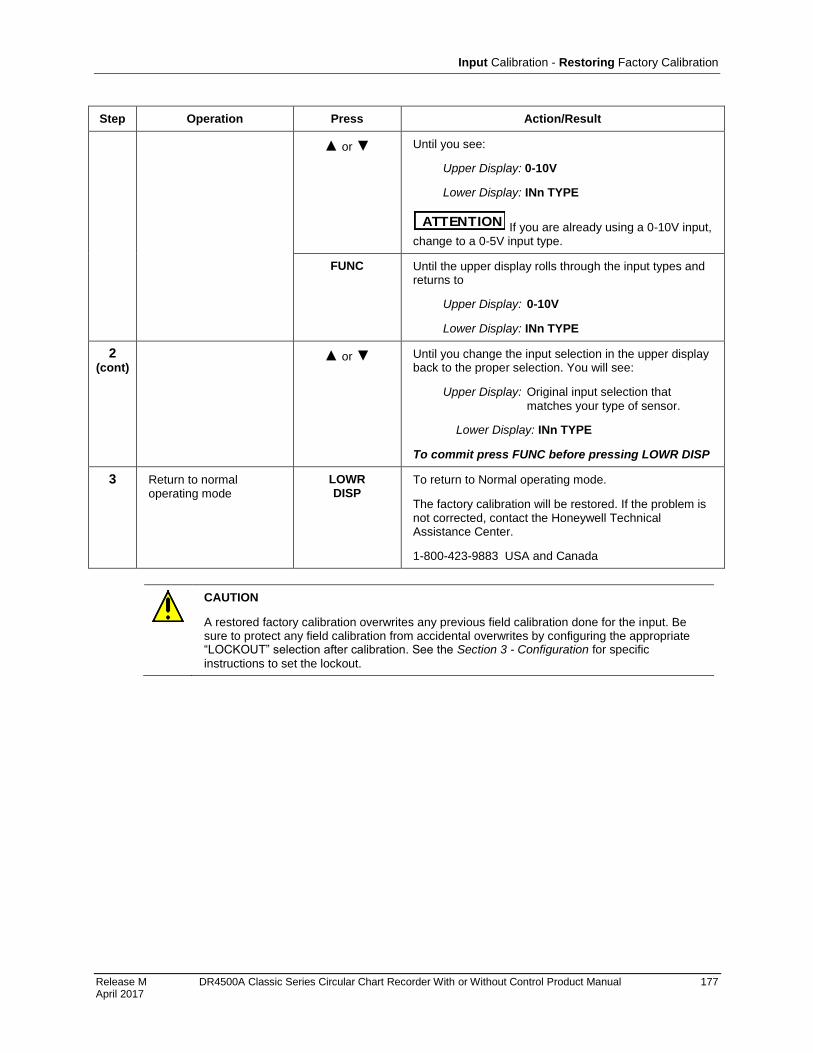
Input Calibration - Restoring Factory Calibration
Release M DR4500A Classic Series Circular Chart Recorder With or Without Control Product Manual 177 April 2017
Step Operation Press Action/Result
or Until you see:
Upper Display: 0-10V
Lower Display: INn TYPE
ATTENTION If you are already using a 0-10V input, change to a 0-5V input type.
FUNC Until the upper display rolls through the input types and returns to
Upper Display: 0-10V
Lower Display: INn TYPE
2 (cont)
or
Until you change the input selection in the upper display back to the proper selection. You will see:
Upper Display: Original input selection that
matches your type of sensor.
Lower Display: INn TYPE
To commit press FUNC before pressing LOWR DISP
3 Return to normal operating mode
LOWR DISP
To return to Normal operating mode.
The factory calibration will be restored. If the problem is not corrected, contact the Honeywell Technical Assistance Center.
1-800-423-9883 USA and Canada
CAUTION
A restored factory calibration overwrites any previous field calibration done for the input. Be sure to protect any field calibration from accidental overwrites by configuring the appropriate “LOCKOUT” selection after calibration. See the Section 3 - Configuration for specific
instructions to set the lockout.
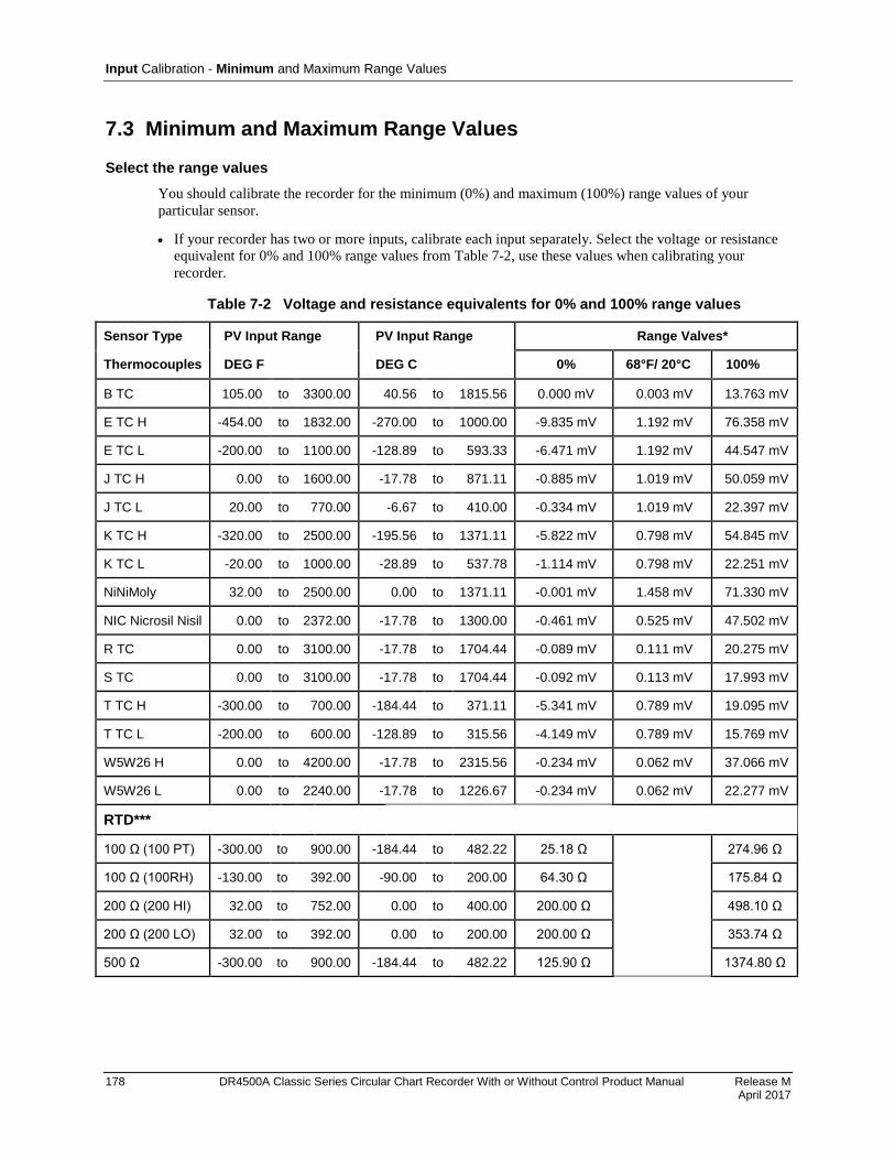
Input Calibration - Minimum and Maximum Range Values
178 DR4500A Classic Series Circular Chart Recorder With or Without Control Product Manual Release M April 2017
7.3 Minimum and Maximum Range Values
Select the range values
You should calibrate the recorder for the minimum (0%) and maximum (100%) range values of your
particular sensor.
If your recorder has two or more inputs, calibrate each input separately. Select the voltage or resistance
equivalent for 0% and 100% range values from Table 7-2, use these values when calibrating your
recorder.
Table 7-2 Voltage and resistance equivalents for 0% and 100% range values
Sensor Type PV Input Range PV Input Range Range Valves*
Thermocouples DEG F DEG C 0% 68°F/ 20°C 100%
B TC 105.00 to 3300.00 40.56 to 1815.56 0.000 mV 0.003 mV 13.763 mV
E TC H -454.00 to 1832.00 -270.00 to 1000.00 -9.835 mV 1.192 mV 76.358 mV
E TC L -200.00 to 1100.00 -128.89 to 593.33 -6.471 mV 1.192 mV 44.547 mV
J TC H 0.00 to 1600.00 -17.78 to 871.11 -0.885 mV 1.019 mV 50.059 mV
J TC L 20.00 to 770.00 -6.67 to 410.00 -0.334 mV 1.019 mV 22.397 mV
K TC H -320.00 to 2500.00 -195.56 to 1371.11 -5.822 mV 0.798 mV 54.845 mV
K TC L -20.00 to 1000.00 -28.89 to 537.78 -1.114 mV 0.798 mV 22.251 mV
NiNiMoly 32.00 to 2500.00 0.00 to 1371.11 -0.001 mV 1.458 mV 71.330 mV
NIC Nicrosil Nisil 0.00 to 2372.00 -17.78 to 1300.00 -0.461 mV 0.525 mV 47.502 mV
R TC 0.00 to 3100.00 -17.78 to 1704.44 -0.089 mV 0.111 mV 20.275 mV
S TC 0.00 to 3100.00 -17.78 to 1704.44 -0.092 mV 0.113 mV 17.993 mV
T TC H -300.00 to 700.00 -184.44 to 371.11 -5.341 mV 0.789 mV 19.095 mV
T TC L -200.00 to 600.00 -128.89 to 315.56 -4.149 mV 0.789 mV 15.769 mV
W5W26 H 0.00 to 4200.00 -17.78 to 2315.56 -0.234 mV 0.062 mV 37.066 mV
W5W26 L 0.00 to 2240.00 -17.78 to 1226.67 -0.234 mV 0.062 mV 22.277 mV
RTD***
100 Ω (100 PT) -300.00 to 900.00 -184.44 to 482.22 25.18 Ω 274.96 Ω
100 Ω (100RH) -130.00 to 392.00 -90.00 to 200.00 64.30 Ω 175.84 Ω
200 Ω (200 HI) 32.00 to 752.00 0.00 to 400.00 200.00 Ω 498.10 Ω
200 Ω (200 LO) 32.00 to 392.00 0.00 to 200.00 200.00 Ω 353.74 Ω
500 Ω -300.00 to 900.00 -184.44 to 482.22 125.90 Ω 1374.80 Ω
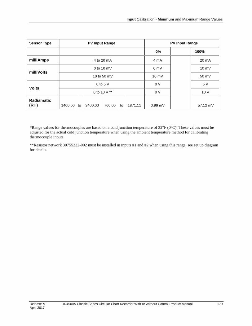
Input Calibration - Minimum and Maximum Range Values
Release M DR4500A Classic Series Circular Chart Recorder With or Without Control Product Manual 179 April 2017
Sensor Type PV Input Range PV Input Range
0% 100%
milliAmps 4 to 20 mA 4 mA 20 mA
milliVolts 0 to 10 mV 0 mV 10 mV
10 to 50 mV 10 mV 50 mV
Volts 0 to 5 V 0 V 5 V
0 to 10 V ** 0 V 10 V
Radiamatic (RH) 1400.00 to 3400.00 760.00 to 1871.11 0.99 mV 57.12 mV
*Range values for thermocouples are based on a cold junction temperature of 32°F (0°C). These values must be
adjusted for the actual cold junction temperature when using the ambient temperature method for calibrating
thermocouple inputs.
**Resistor network 30755232-002 must be installed in inputs #1 and #2 when using this range, see set up diagram
for details.
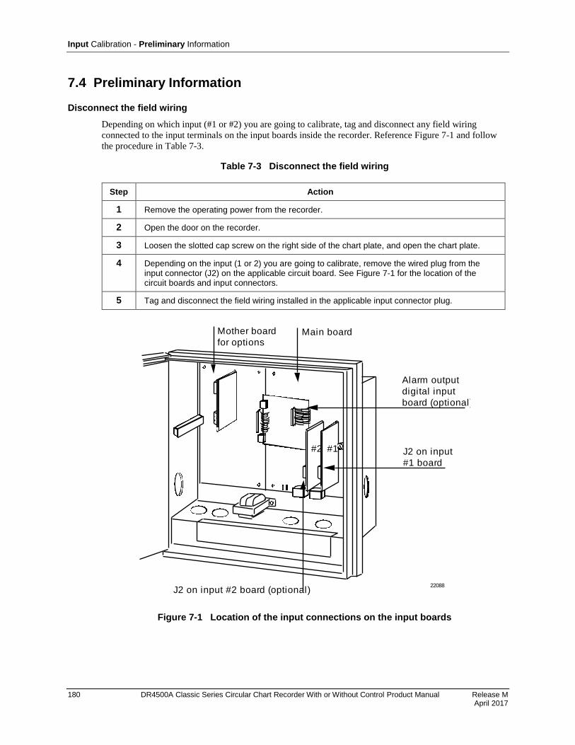
Input Calibration - Preliminary Information
180 DR4500A Classic Series Circular Chart Recorder With or Without Control Product Manual Release M April 2017
7.4 Preliminary Information
Disconnect the field wiring
Depending on which input (#1 or #2) you are going to calibrate, tag and disconnect any field wiring
connected to the input terminals on the input boards inside the recorder. Reference Figure 7-1 and follow
the procedure in Table 7-3.
Table 7-3 Disconnect the field wiring
Step Action
1 Remove the operating power from the recorder.
2 Open the door on the recorder.
3 Loosen the slotted cap screw on the right side of the chart plate, and open the chart plate.
4 Depending on the input (1 or 2) you are going to calibrate, remove the wired plug from the input connector (J2) on the applicable circuit board. See Figure 7-1 for the location of the circuit boards and input connectors.
5 Tag and disconnect the field wiring installed in the applicable input connector plug.
#2 #1
Mother board
for options
22088
Main board
Alarm output
digital input
board (optional)
J2 on input
#1 board
J2 on input #2 board (optional)
Figure 7-1 Location of the input connections on the input boards

Input Calibration - Preliminary Information
Release M DR4500A Classic Series Circular Chart Recorder With or Without Control Product Manual 181 April 2017
Equipment needed
Table 7-4 lists the equipment required to calibrate the specific types of inputs listed in the table. You will
need a medium size bladed screwdriver for general use and a small size bladed screwdriver for use with the
screws on the connector plugs.
Table 7-4 Equipment needed
Type of Input Equipment Needed
Thermocouple Inputs (Ice Bath)
A calibrating device with ±0.02% accuracy for use as a signal source such as a millivolt source.
Thermocouple extension wire that corresponds with the type of thermocouple that will be used with the recorder input.
Two insulated copper leads for connecting the thermocouple extension wire from the ice baths to the precision calibrator.
Two containers of crushed ice.
Thermocouple Inputs (Ambient Temperature)
A calibrating device with ±0.02% accuracy for use as a signal source such as a millivolt source.
Two insulated copper leads for connecting the calibrator to the recorder.
Thermocouple Inputs (Compensated Calibrator)
A calibrating device with temperature compensation and ±0.02% accuracy for use as a signal source.
Thermocouple extension wire that corresponds with the type of thermocouple that will be used with the recorder input.
RTD (Resistance Thermometer Device)
A resistance decade box, with ±0.02% accuracy, capable of providing stepped resistance values over a minimum range of 0 to 1400 ohms with a resolution of 0.01 ohm.
Three insulated copper leads for connecting the decade box to the controller.
Radiamatic, Milliampere, Millivolt, and Volts Inputs
A calibrating device with ±0.02% accuracy for use as a signal source.
Two insulated copper leads for connecting the calibrator to the controller.

Input Calibration - Calibration Set Up and Wiring for PV Inputs
182 DR4500A Classic Series Circular Chart Recorder With or Without Control Product Manual Release M April 2017
7.5 Calibration Set Up and Wiring for PV Inputs
Jumper positions
Before starting the calibration activity, check that the jumper plugs on the applicable input circuit board are
installed in the proper jumper position (in W1/MA and W3) for the particular sensor being used (refer to
the wiring connection drawings in this section for each individual setting).
Refer to Figure 7-2 for the location of jumper positions W1/MA and W3 on these circuit boards, and the
status of these jumpers for each type of input sensor.
Main board
Input board
W1
MA
MA
Position MA Position W1
Status of jumper plugs
1. Install W1/MA plug in position W1 f or thermocouple, RTD, Radiamatic, mV, 0-5 Vdc, 0-10 Vdc inputs.
2. Install W1/MA plug in position MA f or 4-20 mA inputs.
21443
RT
DW
3
Position
T/C
MA
Linear
Position
RTD
3. Install plug in W3 according to y our input ty pe.
T/C
Figure 7-2 Location of jumper positions W1/MA and W3 on the input boards

Input Calibration - Calibration Set Up and Wiring for PV Inputs
Release M DR4500A Classic Series Circular Chart Recorder With or Without Control Product Manual 183 April 2017
Thermocouple input calibration methods
You can calibrate for a thermocouple input using one of three methods:
using an ice bath,
using a compensated calibrator, or
by measuring the ambient temperature at the input terminals and subtracting the voltage contribution
of the input terminal junction.
General set up procedure
Table 7-5 lists the general set up procedure for all methods of calibration. Do this procedure and then refer
to the set up procedure and diagram for your specific input.
Table 7-5 General set up procedure
Step Action
1 Set up and connect the calibrator to the input plug for the applicable input circuit board in your recorder according to the particular input sensor being used. Refer to the following figures for corresponding set-up diagrams:
Figure 7-3 Thermocouple inputs using an ice bath
Figure 7-4 Thermocouple inputs using a compensated calibrator
Figure 7-5 Thermocouple inputs using the ambient temperature method
Figure 7-6 RTD (Resistance Thermometer Device) inputs
Figure 7-7 Radiamatic, mV and Volts (except 0–10 Volts) inputs
Figure 7-8 0-10 Volts input
Figure 7-9 4–20 mA inputs
2 Route leads (for example: copper leads or thermocouple extension wires) through a conduit hole in the recorder case so that you will be able to close the chart plate.
3 Close the chart plate after you have completed the applicable calibration set up.
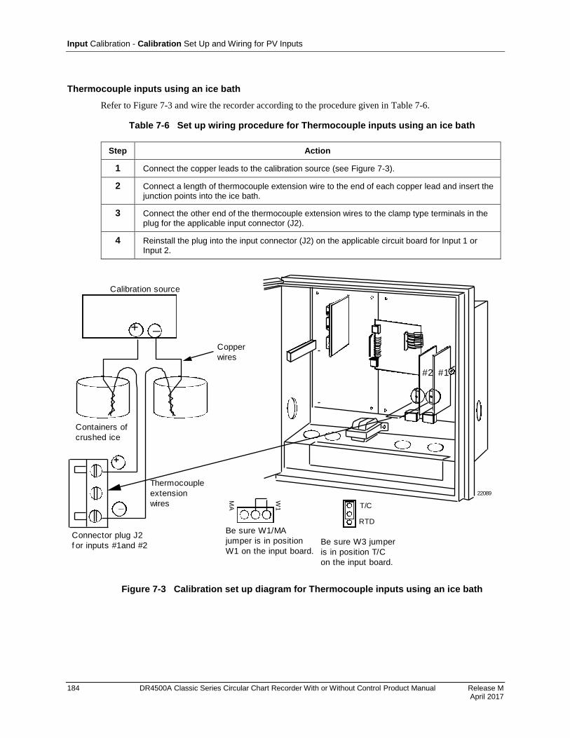
Input Calibration - Calibration Set Up and Wiring for PV Inputs
184 DR4500A Classic Series Circular Chart Recorder With or Without Control Product Manual Release M April 2017
Thermocouple inputs using an ice bath
Refer to Figure 7-3 and wire the recorder according to the procedure given in Table 7-6.
Table 7-6 Set up wiring procedure for Thermocouple inputs using an ice bath
Step Action
1 Connect the copper leads to the calibration source (see Figure 7-3).
2 Connect a length of thermocouple extension wire to the end of each copper lead and insert the junction points into the ice bath.
3 Connect the other end of the thermocouple extension wires to the clamp type terminals in the plug for the applicable input connector (J2).
4 Reinstall the plug into the input connector (J2) on the applicable circuit board for Input 1 or Input 2.
#2 #1
22089
Containers of
crushed ice
+
_
_+
Copper
wires
Calibration source
Thermocouple
extension
wires
Connector plug J2
f or inputs #1and #2
MA
W1
Be sure W1/MA
jumper is in position
W1 on the input board.
T/C
RTD
Be sure W3 jumper
is in position T/C
on the input board.
Figure 7-3 Calibration set up diagram for Thermocouple inputs using an ice bath
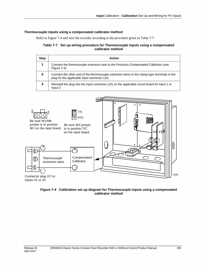
Input Calibration - Calibration Set Up and Wiring for PV Inputs
Release M DR4500A Classic Series Circular Chart Recorder With or Without Control Product Manual 185 April 2017
Thermocouple inputs using a compensated calibrator method
Refer to Figure 7-4 and wire the recorder according to the procedure given in Table 7-7.
Table 7-7 Set up wiring procedure for Thermocouple inputs using a compensated calibrator method
Step Action
1 Connect the thermocouple extension wire to the Precision Compensated Calibrator (see Figure 7-4).
2 Connect the other end of the thermocouple extension wires to the clamp type terminals in the plug for the applicable input connector (J2).
3 Reinstall the plug into the input connector (J2) on the applicable circuit board for Input 1 or Input 2.
#2 #1
22090Connector plug J2 f or
inputs #1 or #2
+
_
Thermocouple
extension wires
_
+
Compensated
Calibrator
MA W
1
Be sure W1/MA
jumper is in position
W1 on the input board.
T/C
RTD
Be sure W3 jumper
is in position T/C
on the input board.
Figure 7-4 Calibration set up diagram for Thermocouple inputs using a compensated calibrator method
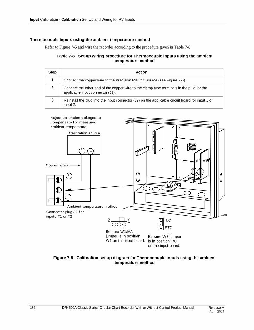
Input Calibration - Calibration Set Up and Wiring for PV Inputs
186 DR4500A Classic Series Circular Chart Recorder With or Without Control Product Manual Release M April 2017
Thermocouple inputs using the ambient temperature method
Refer to Figure 7-5 and wire the recorder according to the procedure given in Table 7-8.
Table 7-8 Set up wiring procedure for Thermocouple inputs using the ambient temperature method
Step Action
1 Connect the copper wire to the Precision Millivolt Source (see Figure 7-5).
2 Connect the other end of the copper wire to the clamp type terminals in the plug for the applicable input connector (J2).
3 Reinstall the plug into the input connector (J2) on the applicable circuit board for input 1 or input 2.
#2 #1
22091
+
_
_+
Calibration source
Connector plug J2 f or
inputs #1 or #2
Copper wires
Adjust calibration v oltages to
compensate f or measured
ambient temperature
Ambient temperature method
MA
W1
Be sure W1/MA
jumper is in position
W1 on the input board.
T/C
RTD
Be sure W3 jumper
is in position T/C
on the input board.
Figure 7-5 Calibration set up diagram for Thermocouple inputs using the ambient temperature method

Input Calibration - Calibration Set Up and Wiring for PV Inputs
Release M DR4500A Classic Series Circular Chart Recorder With or Without Control Product Manual 187 April 2017
RTD (Resistance Thermometer Device) inputs
Refer to Figure 7-6 and wire the recorder according to the procedure given in Table 7-9.
Table 7-9 Set up wiring procedure for RTD inputs
Step Action
1 Connect the copper wire to the calibration source (see Figure 7-6).
2 Connect the other end of the copper wire to the clamp type terminals in the plug for the applicable input connector (J2).
3 Reinstall the plug into the input connector (J2) on the applicable circuit board for input 1 or input 2.
#2 #1
22092
+
_
Copper wires
Decade box
Plug J2
MA
W1
Be sure W1/MA
jumper is in position
W1 on the input board.
T/C
RTD
Be sure W3 jumper
is in position RTD
on the input board.
Figure 7-6 Calibration set up diagram for RTD inputs
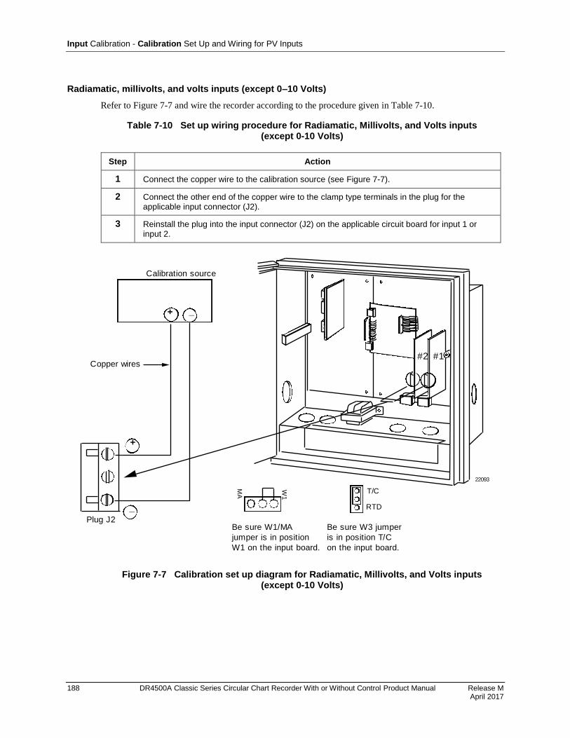
Input Calibration - Calibration Set Up and Wiring for PV Inputs
188 DR4500A Classic Series Circular Chart Recorder With or Without Control Product Manual Release M April 2017
Radiamatic, millivolts, and volts inputs (except 0–10 Volts)
Refer to Figure 7-7 and wire the recorder according to the procedure given in Table 7-10.
Table 7-10 Set up wiring procedure for Radiamatic, Millivolts, and Volts inputs (except 0-10 Volts)
Step Action
1 Connect the copper wire to the calibration source (see Figure 7-7).
2 Connect the other end of the copper wire to the clamp type terminals in the plug for the applicable input connector (J2).
3 Reinstall the plug into the input connector (J2) on the applicable circuit board for input 1 or input 2.
#2 #1
22093
+
_
Copper wires
_+
Calibration source
Plug J2
MA
W1
Be sure W1/MA
jumper is in position
W1 on the input board.
T/C
RTD
Be sure W3 jumper
is in position T/C
on the input board.
Figure 7-7 Calibration set up diagram for Radiamatic, Millivolts, and Volts inputs (except 0-10 Volts)
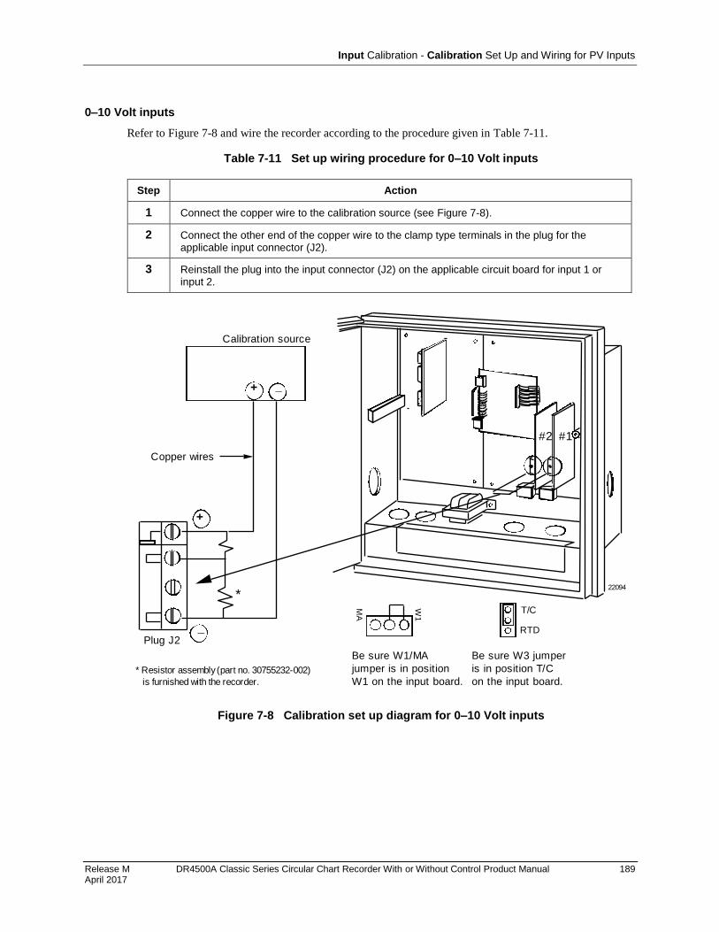
Input Calibration - Calibration Set Up and Wiring for PV Inputs
Release M DR4500A Classic Series Circular Chart Recorder With or Without Control Product Manual 189 April 2017
0–10 Volt inputs
Refer to Figure 7-8 and wire the recorder according to the procedure given in Table 7-11.
Table 7-11 Set up wiring procedure for 0–10 Volt inputs
Step Action
1 Connect the copper wire to the calibration source (see Figure 7-8).
2 Connect the other end of the copper wire to the clamp type terminals in the plug for the applicable input connector (J2).
3 Reinstall the plug into the input connector (J2) on the applicable circuit board for input 1 or input 2.
#2 #1
22094
+
_
Copper wires
_+
Calibration source
Plug J2
*
* Resistor assembly (part no. 30755232-002)
is furnished with the recorder.
MA
W1
Be sure W1/MA
jumper is in position
W1 on the input board.
T/C
RTD
Be sure W3 jumper
is in position T/C
on the input board.
Figure 7-8 Calibration set up diagram for 0–10 Volt inputs

Input Calibration - Calibration Set Up and Wiring for PV Inputs
190 DR4500A Classic Series Circular Chart Recorder With or Without Control Product Manual Release M April 2017
4–20 mA inputs
Refer to Figure 7-9 and wire the recorder according to the procedure given in Table 7-12.
Table 7-12 Set up wiring procedure for 4–20 mA inputs
Step Action
1 Connect the copper wire to the calibration source (see Figure 7-9).
2 Connect the other end of the copper wire to the clamp type terminals in the plug for the applicable input connector (J2).
3 Reinstall the plug into the input connector (J2) on the applicable circuit board for input 1 or input 2.
#2 #1
22305
+
_
_+
Copper wires
Calibration source
Plug J2
MA
W1
Be sure W1/MA jumper is in
position MA; this connects
250 resistor (internal on
PCB) across inputs terminals
4-20 mA
T/C
RTD
Be sure W3 jumper
is in position T/C
on the input board.
Figure 7-9 Calibration set up diagram for 4–20 mA inputs
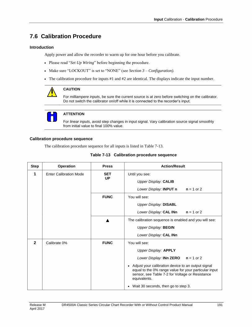
Input Calibration - Calibration Procedure
Release M DR4500A Classic Series Circular Chart Recorder With or Without Control Product Manual 191 April 2017
7.6 Calibration Procedure
Introduction
Apply power and allow the recorder to warm up for one hour before you calibrate.
Please read “Set Up Wiring” before beginning the procedure.
Make sure “LOCKOUT” is set to “NONE” (see Section 3 – Configuration).
The calibration procedure for inputs #1 and #2 are identical. The displays indicate the input number.
CAUTION
For milliampere inputs, be sure the current source is at zero before switching on the calibrator.
Do not switch the calibrator on/off while it is connected to the recorder’s input.
ATTENTION
For linear inputs, avoid step changes in input signal. Vary calibration source signal smoothly from initial value to final 100% value.
Calibration procedure sequence
The calibration procedure sequence for all inputs is listed in Table 7-13.
Table 7-13 Calibration procedure sequence
Step Operation Press Action/Result
1 Enter Calibration Mode SET UP
Until you see:
Upper Display: CALIB
Lower Display: INPUT n n = 1 or 2
FUNC You will see:
Upper Display: DISABL
Lower Display: CAL INn n = 1 or 2
The calibration sequence is enabled and you will see:
Upper Display: BEGIN
Lower Display: CAL INn
2 Calibrate 0% FUNC You will see:
Upper Display: APPLY
Lower Display: INn ZERO n = 1 or 2
Adjust your calibration device to an output signal equal to the 0% range value for your particular input sensor, see Table 7-2 for Voltage or Resistance equivalents.
Wait 30 seconds, then go to step 3.
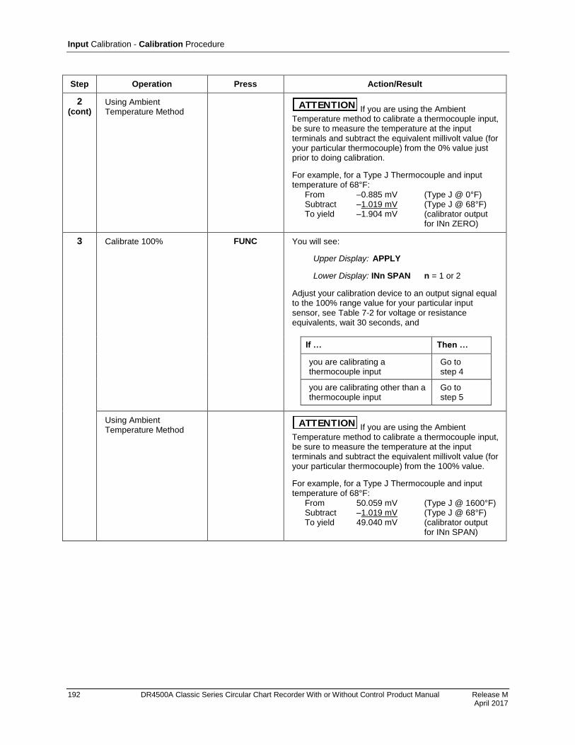
Input Calibration - Calibration Procedure
192 DR4500A Classic Series Circular Chart Recorder With or Without Control Product Manual Release M April 2017
Step Operation Press Action/Result
2 (cont)
Using Ambient Temperature Method
ATTENTION If you are using the Ambient Temperature method to calibrate a thermocouple input, be sure to measure the temperature at the input terminals and subtract the equivalent millivolt value (for your particular thermocouple) from the 0% value just prior to doing calibration.
For example, for a Type J Thermocouple and input temperature of 68°F: From –0.885 mV (Type J @ 0°F) Subtract –1.019 mV (Type J @ 68°F) To yield –1.904 mV (calibrator output for INn ZERO)
3 Calibrate 100% FUNC You will see:
Upper Display: APPLY
Lower Display: INn SPAN n = 1 or 2
Adjust your calibration device to an output signal equal to the 100% range value for your particular input sensor, see Table 7-2 for voltage or resistance equivalents, wait 30 seconds, and
If … Then …
you are calibrating a thermocouple input
Go to step 4
you are calibrating other than a thermocouple input
Go to step 5
Using Ambient Temperature Method
ATTENTION If you are using the Ambient Temperature method to calibrate a thermocouple input, be sure to measure the temperature at the input terminals and subtract the equivalent millivolt value (for your particular thermocouple) from the 100% value.
For example, for a Type J Thermocouple and input temperature of 68°F: From 50.059 mV (Type J @ 1600°F) Subtract –1.019 mV (Type J @ 68°F) To yield 49.040 mV (calibrator output for INn SPAN)

Input Calibration - Calibration Procedure
Release M DR4500A Classic Series Circular Chart Recorder With or Without Control Product Manual 193 April 2017
Step Operation Press Action/Result
4 Check the Cold Junction Temperature
W ARNING The accuracy of the recorder is directly affected by the accuracy of this value. Change this value only if the zero and span calibration procedures did not bring the recorder within the specified accuracy requirements.
FUNC The calculations for zero and span are now stored and you will see:
Upper Display: The cold junction temperature at the rear terminals
Lower Display: C-J TEMP
The value in the upper display is in the tenths of a degree. It is the current reading of the temperature as measured at the thermocouple terminals (that is, at J2) and recognized by the recorder.
When using the Ice Bath method, this value should be the terminal ambient temperature.
You can change this value, if it is in error, using the or key.
5 Exit the Calibration Mode LOWR DISP
or
SET UP
The recorder stores the calibration constants and exit calibration mode.

194
Release K DR4500A Classic Series Circular Chart Recorder With or Without Control Product Manual 194 May 2013
8. Output Calibration
8.1 Overview
SHOCK HAZARD—WARNING! Disregard of these instructions may cause injury or death.
OUTPUT CALIBRATION MAY REQUIRE ACCESS TO HAZARDOUS LIVE CIRCUITS, AND SHOULD ONLY BE PERFORMED BY QUALIFIED SERVICE PERSONNEL. MORE THAN ONE SWITCH MAY BE REQUIRED TO DE-ENERGIZE UNIT BEFORE CALIBRATION.
Introduction
This section describes the field calibration procedures for the following types of outputs:
Current Output
Position Proportional Output
Auxiliary Output
ATTENTION
Calibration for Control Outputs #1 and #2 is identical except for the particular printed circuit board involved.
What’s in this section
This section contains the following topics:
Topic See Page
8.1 Overview 194
8.2 Current Proportional Output/Aux Out 2 and 3 Calibration Introduction Equipment needed Calibrator connections Calibration Procedure
195 195 195 195 196
8.3 Position Proportional Output Calibration Position proportional control Equipment needed Connections Auto mode vs manual mode Displayed values Calibration Procedure
197 197 197 197 197 197 197
8.4 Auxiliary Output Calibration Introduction Equipment needed Calibrator connections Calibration Procedure
200 200 200 200 200
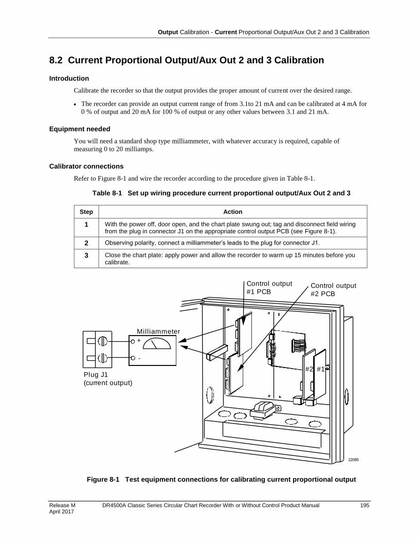
Output Calibration - Current Proportional Output/Aux Out 2 and 3 Calibration
Release M DR4500A Classic Series Circular Chart Recorder With or Without Control Product Manual 195 April 2017
8.2 Current Proportional Output/Aux Out 2 and 3 Calibration
Introduction
Calibrate the recorder so that the output provides the proper amount of current over the desired range.
The recorder can provide an output current range of from 3.1to 21 mA and can be calibrated at 4 mA for
0 % of output and 20 mA for 100 % of output or any other values between 3.1 and 21 mA.
Equipment needed
You will need a standard shop type milliammeter, with whatever accuracy is required, capable of
measuring 0 to 20 milliamps.
Calibrator connections
Refer to Figure 8-1 and wire the recorder according to the procedure given in Table 8-1.
Table 8-1 Set up wiring procedure current proportional output/Aux Out 2 and 3
Step Action
1 With the power off, door open, and the chart plate swung out; tag and disconnect field wiring from the plug in connector J1 on the appropriate control output PCB (see Figure 8-1).
2 Observing polarity, connect a milliammeter’s leads to the plug for connector J1.
3 Close the chart plate: apply power and allow the recorder to warm up 15 minutes before you calibrate.
22095
Milliammeter
Plug J1
(current output)
+
-
Control output
#1 PCB
#2 #1
Control output
#2 PCB
Figure 8-1 Test equipment connections for calibrating current proportional output

Output Calibration - Current Proportional Output/Aux Out 2 and 3 Calibration
196 DR4500A Classic Series Circular Chart Recorder With or Without Control Product Manual Release M April 2017
Procedure
The procedure for calibrating the Current Proportional Output is listed in Table 8-2. Make sure
“LOCKOUT” in the Set Up group is set to “NONE.” See Section 3 – Configuration. Also, “CONTROL
1/2” must be enabled and “OUT ALG” must be set to “CURRNT” in the Control Set Up group.
ATTENTION
Follow this procedure when calibrating Auxiliary Output #2 or #3. Make sure "LOCKOUT" in the Set Up group is set to "NONE" and "AUX OUT" must NOT be disabled in the Auxiliary
Output group.
Table 8-2 Current proportional output/Aux Out 2 and 3 calibration procedure
Step Operation Press Action/Result
1 Enter Calibration Mode SET UP
Until you see:
Upper Display: CALIB
Lower Display: CURRENT
2 Calibrate 0 % FUNC You will see:
Upper Display: (a value) (approximately 380)
Lower Display: ZERO VAL
or Until the desired 0 % output is read on the milliammeter. Use the values shown below depending on the action of your recorder.
4 mA For 4 to 20 mA Direct Action 20 mA For 4 to 20 mA Reverse Action
3 Calibrate 100 % FUNC Stores the 0 % value and you will see:
Upper Display: (a value) (approximately 1890)
Lower Display: SPAN VAL
or Until the desired 100 % output is read on the milliammeter. Use the values shown below depending on the action of your recorder.
20 mA For 4 to 20 mA Direct Action 4 mA For 4 to 20 mA Reverse Action
4 Exit the Calibration Mode FUNC The recorder stores the span value.
LOWR DISP
or
SET UP
To exit the calibration mode.

Output Calibration - Position Proportional Output Calibration
Release M DR4500A Classic Series Circular Chart Recorder With or Without Control Product Manual 197 April 2017
8.3 Position Proportional Output Calibration
Position proportional control
When the DR4500A Recorder has a position proportional control output, calibrate the recorder so that the
increase and decrease relays operate properly with respect to the position of the external feedback
slidewire.
Equipment needed
None
Connections
Leave all field wiring connected to the plugs in connectors J2 and J5 on the appropriate control output
printed circuit board.
Apply power and allow the recorder to warm up 15 minutes before you calibrate.
Auto mode vs manual mode
There are two ways in which to calibrate Position Proportional control:
AUTO mode or MANUAL mode.
Rules for auto mode vs manual mode
The auto-mode selection must be done at least once before the manual mode will operate properly. Failure
to use the auto-mode procedure will prevent the recorder from going into automatic control mode.
Displayed values
During the auto-mode calibration procedure, the values being displayed are used only to indicate if the
motor is still traveling.
To view the actual calibration value, use the manual mode after the auto-mode is completed. These values
can be changed for purposes of tweaking the calibration.
Procedure
The procedure for calibrating the position proportional output control output is listed in Table 8-3.
Make sure “LOCKOUT” in the Set Up group is set to “NONE.” See Section 3 – Configuration. Also,
“CONTROL 1/2” must be enabled in the Control Set Up group.
Make sure “CONT ALG” = “PID A” and “OUT ALG” = “POSITN” in the Control Set Up group.
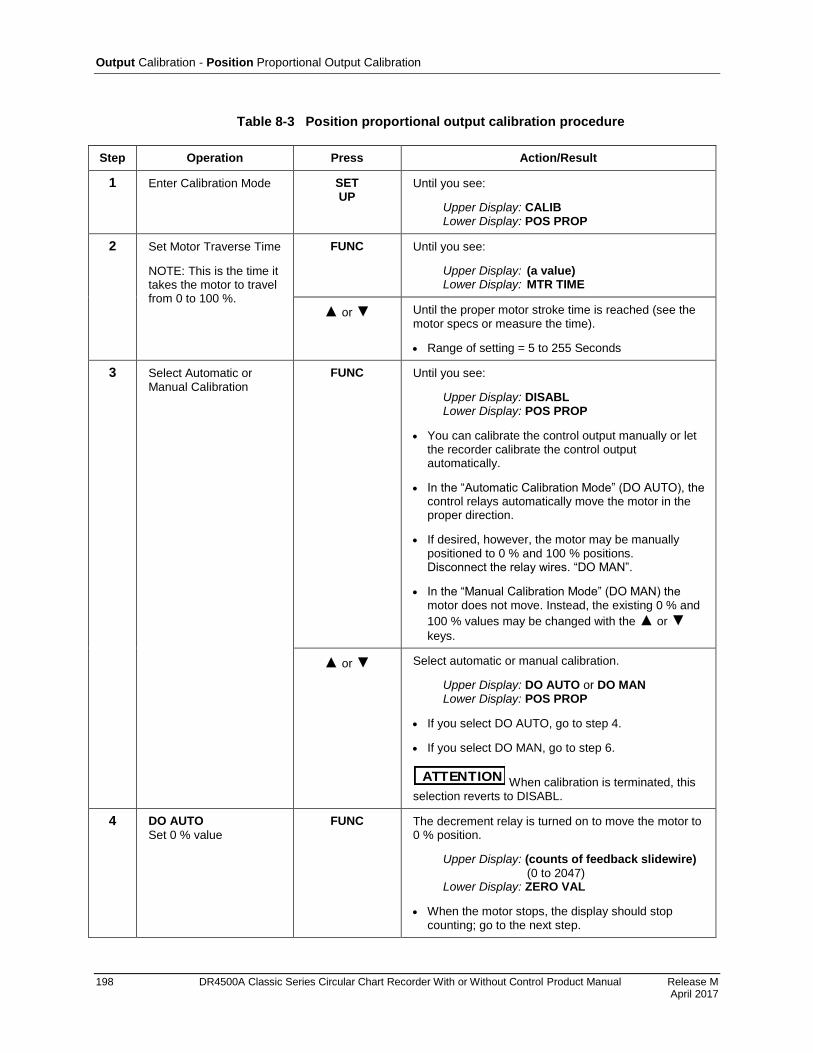
Output Calibration - Position Proportional Output Calibration
198 DR4500A Classic Series Circular Chart Recorder With or Without Control Product Manual Release M April 2017
Table 8-3 Position proportional output calibration procedure
Step Operation Press Action/Result
1 Enter Calibration Mode SET UP
Until you see:
Upper Display: CALIB Lower Display: POS PROP
2 Set Motor Traverse Time
NOTE: This is the time it takes the motor to travel from 0 to 100 %.
FUNC Until you see:
Upper Display: (a value) Lower Display: MTR TIME
or Until the proper motor stroke time is reached (see the motor specs or measure the time).
Range of setting = 5 to 255 Seconds
3 Select Automatic or Manual Calibration
FUNC Until you see:
Upper Display: DISABL Lower Display: POS PROP
You can calibrate the control output manually or let the recorder calibrate the control output automatically.
In the “Automatic Calibration Mode” (DO AUTO), the control relays automatically move the motor in the proper direction.
If desired, however, the motor may be manually positioned to 0 % and 100 % positions. Disconnect the relay wires. “DO MAN”.
In the “Manual Calibration Mode” (DO MAN) the motor does not move. Instead, the existing 0 % and
100 % values may be changed with the or
keys.
or Select automatic or manual calibration.
Upper Display: DO AUTO or DO MAN Lower Display: POS PROP
If you select DO AUTO, go to step 4.
If you select DO MAN, go to step 6.
ATTENTION When calibration is terminated, this selection reverts to DISABL.
4 DO AUTO
Set 0 % value
FUNC The decrement relay is turned on to move the motor to 0 % position.
Upper Display: (counts of feedback slidewire)
(0 to 2047) Lower Display: ZERO VAL
When the motor stops, the display should stop counting; go to the next step.
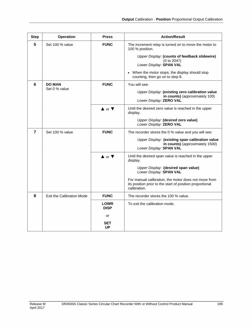
Output Calibration - Position Proportional Output Calibration
Release M DR4500A Classic Series Circular Chart Recorder With or Without Control Product Manual 199 April 2017
Step Operation Press Action/Result
5 Set 100 % value FUNC The increment relay is turned on to move the motor to 100 % position.
Upper Display: (counts of feedback slidewire)
(0 to 2047) Lower Display: SPAN VAL
When the motor stops, the display should stop counting, then go on to step 8.
6 DO MAN
Set 0 % value
FUNC You will see:
Upper Display: (existing zero calibration value in counts) (approximately 100)
Lower Display: ZERO VAL
or Until the desired zero value is reached in the upper display.
Upper Display: (desired zero value) Lower Display: ZERO VAL
7 Set 100 % value FUNC The recorder stores the 0 % value and you will see:
Upper Display: (existing span calibration value in counts) (approximately 1500)
Lower Display: SPAN VAL
or Until the desired span value is reached in the upper display.
Upper Display: (desired span value) Lower Display: SPAN VAL
For manual calibration, the motor does not move from its position prior to the start of position proportional calibration.
8 Exit the Calibration Mode FUNC The recorder stores the 100 % value.
LOWR DISP
or
SET UP
To exit the calibration mode.
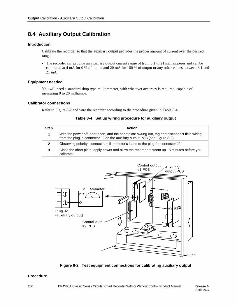
Output Calibration - Auxiliary Output Calibration
200 DR4500A Classic Series Circular Chart Recorder With or Without Control Product Manual Release M April 2017
8.4 Auxiliary Output Calibration
Introduction
Calibrate the recorder so that the auxiliary output provides the proper amount of current over the desired
range.
The recorder can provide an auxiliary output current range of from 3.1 to 21 milliamperes and can be
calibrated at 4 mA for 0 % of output and 20 mA for 100 % of output or any other values between 3.1 and
21 mA.
Equipment needed
You will need a standard shop type milliammeter, with whatever accuracy is required, capable of
measuring 0 to 20 milliamps.
Calibrator connections
Refer to Figure 8-2 and wire the recorder according to the procedure given in Table 8-4.
Table 8-4 Set up wiring procedure for auxiliary output
Step Action
1 With the power off, door open, and the chart plate swung out, tag and disconnect field wiring from the plug in connector J2 on the auxiliary output PCB (see Figure 8-2).
2 Observing polarity, connect a milliammeter’s leads to the plug for connector J2.
3 Close the chart plate; apply power and allow the recorder to warm up 15 minutes before you calibrate.
22818
Milliammeter
Plug J2
(auxiliary output)
+
-
Control output
#1 PCB
#2 #1
Control output
#2 PCB
Auxiliary
output PCB
Figure 8-2 Test equipment connections for calibrating auxiliary output
Procedure
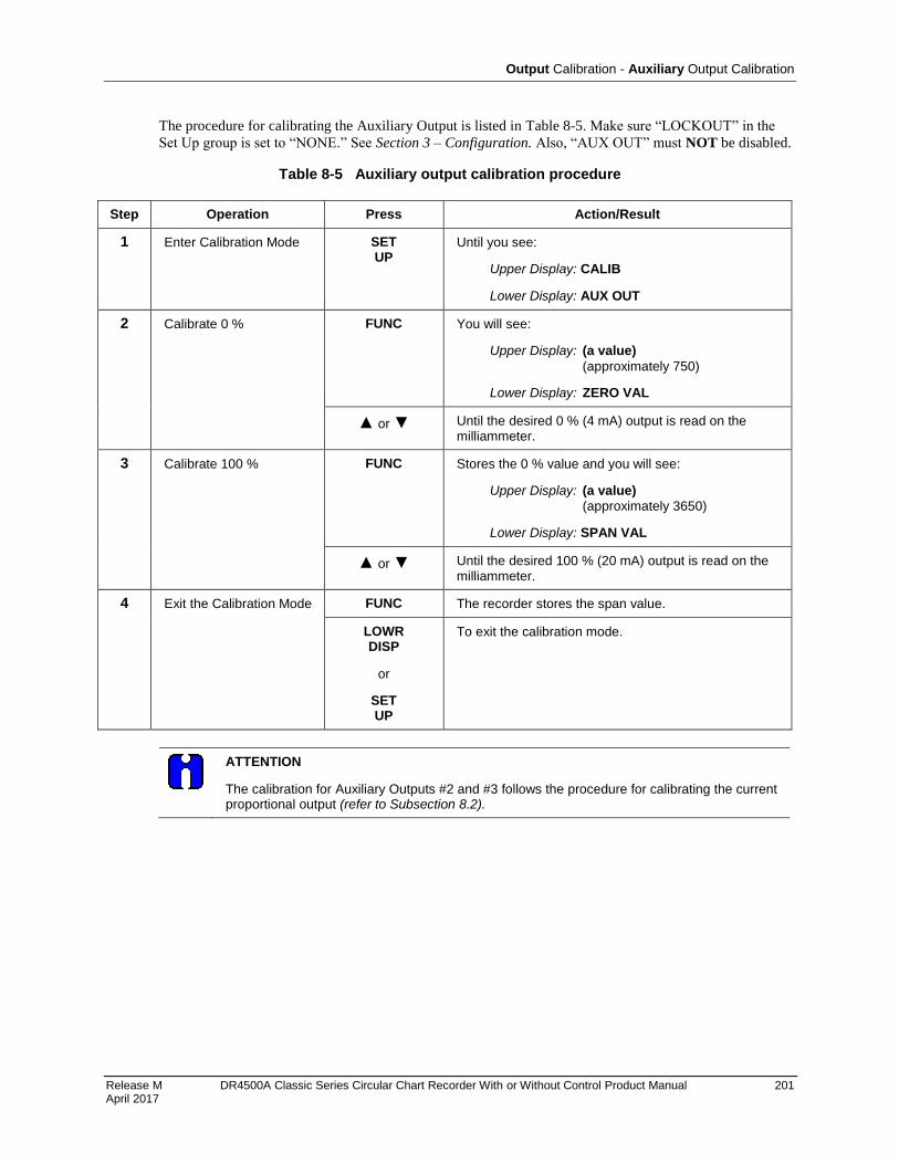
Output Calibration - Auxiliary Output Calibration
Release M DR4500A Classic Series Circular Chart Recorder With or Without Control Product Manual 201 April 2017
The procedure for calibrating the Auxiliary Output is listed in Table 8-5. Make sure “LOCKOUT” in the
Set Up group is set to “NONE.” See Section 3 – Configuration. Also, “AUX OUT” must NOT be disabled.
Table 8-5 Auxiliary output calibration procedure
Step Operation Press Action/Result
1 Enter Calibration Mode SET UP
Until you see:
Upper Display: CALIB
Lower Display: AUX OUT
2 Calibrate 0 % FUNC You will see:
Upper Display: (a value)
(approximately 750)
Lower Display: ZERO VAL
or Until the desired 0 % (4 mA) output is read on the milliammeter.
3 Calibrate 100 % FUNC Stores the 0 % value and you will see:
Upper Display: (a value)
(approximately 3650)
Lower Display: SPAN VAL
or Until the desired 100 % (20 mA) output is read on the milliammeter.
4 Exit the Calibration Mode FUNC The recorder stores the span value.
LOWR DISP
or
SET UP
To exit the calibration mode.
ATTENTION
The calibration for Auxiliary Outputs #2 and #3 follows the procedure for calibrating the current proportional output (refer to Subsection 8.2).

202
Release K DR4500A Classic Series Circular Chart Recorder With or Without Control Product Manual 202 May 2013
9. Troubleshooting / Service
9.1 Overview
SHOCK HAZARD—WARNING! Disregard of these instructions may cause injury or death.
TROUBLESHOOTING MAY REQUIRE ACCESS TO HAZARDOUS LIVE CIRCUITS, AND SHOULD ONLY BE PERFORMED BY QUALIFIED SERVICE PERSONNEL. MORE THAN ONE SWITCH MAY BE REQUIRED TO DE-ENERGIZE UNIT BEFORE SERVICING.
Introduction
This section explains how to troubleshoot the DR4500A recorder using self-diagnostic test results and error
messages as well as some visual failure symptoms. Using an optimum replacement unit repair philosophy,
trouble is traced to a printed circuit board (PCB)/hardware assembly level rather than to an individual
PCB/hardware assembly component. While troubleshooting is straightforward, we recommend that only
trained service technicians repair the recorder.
What’s in this section?
The following topics are covered in this section.
Topic See Page
9.1 Overview 202
9.2 Troubleshooting Aids 204
9.3 Self Diagnostics 206
9.4 Visual Failure Symptoms 212
9.5 Troubleshooting Procedures 213
9.6 Pen Alignment 219
Types of problems
Instrument performance can be adversely affected by installation and application problems as well as
hardware problems. We recommend that you investigate the problems in the following order:
Installation related problems
Application related problems
Hardware and software related problems
and use the information presented in this section to solve them.
If a replacement of any part is required, follow the instructions shipped with the replacment part.
Troubleshooting / Service Overview
Release M DR4500A Classic Series Circular Chart Recorder With or Without Control Product Manual 203 April 2017
Installation related problems
Read the Installation section in this manual to make sure the DR4500A has been properly installed. The
installation section provides information on protection against electrical noise, connecting external
equipment to the recorder, and shielding and routing external wiring.
ATTENTION
System noise induced into the recorder will result in diagnostic error messages recurring. If the diagnostic error messages can be cleared, it indicates a “soft” failure and is probably noise related.
If system noise is suspected, completely isolate the recorder from all field wiring. Use calibration sources to simulate PV and check all recorder and control functions; that is, Pen functions, Chart Trace, Gain, Rate, Reset, Output, Alarms, etc.
Application related problems
Review the application of the recorder; then, if necessary, direct your questions to the local sales office.
Hardware and software related problems
Use the troubleshooting error message prompts and recorder failure symptoms to identify typical failures
which may occur in the recorder. Follow the troubleshooting procedures to correct them.
Troubleshooting / Service Troubleshooting Aids
204 DR4500A Classic Series Circular Chart Recorder With or Without Control Product Manual Release L February 2017
9.2 Troubleshooting Aids
Self diagnostics
The DR4500A recorder runs self-diagnostic tests to monitor the recorder’s general health. The tests are
divided into three main groups and will produce an error message when failed.
An error message can occur
at power-up — run when power is cycled off and on,
during continuous background tests while in normal operation, and
when the Status Tests are requested by the operator.
Table 9-4 lists all the error message prompts that you could see, the reason for the failure, and how to
correct the problem
Visual failure symptoms
Other failures may occur that deal with the power, pen functions, chart rotation, output, or alarms. Refer to
the visual failure symptom in Table 9-5 to determine what is wrong and the troubleshooting procedures to
use to correct the problem.
Check Installation
If a set of symptoms still persists, refer to Section 2 - Installation and ensure proper installation and proper
use of the recorder in the system.
Customer support
If you cannot solve the problem using the troubleshooting procedures listed in this section, get the model
number and serial number from the label on the chart plate, and software version (see "Determining the
software version") then:
call Customer Support Phone Number
1-800-423-9883 USA and Canada
If it is determined that a hardware problem exists and the recorder is still within the two year warranty, a
replacement recorder will be shipped with instructions for returning the defective unit.

Troubleshooting / Service Troubleshooting Aids
Release M DR4500A Classic Series Circular Chart Recorder With or Without Control Product Manual 205 April 2017
Determining the software version
Table 9-1 lists the procedure for identifying the software version number.
Table 9-1 Procedure for identifying the software version
Step Operation Press Action/Result
1 Select STATUS Set Up Group
SET UP
Until you see:
Upper Display: READ Lower Display: STATUS
2 Read the software version
FUNC Until you see:
Upper Display: (Software Version Number) Lower Display: VERSION
Please give this number to the Customer Support person. It will indicate which version of DR4500A you have and help them determine a solution to your problem.
Troubleshooting
The troubleshooting procedures are divided into two parts:
Self Diagnostics - Error Message Prompts, and
Visual Failure Symptoms.
If a “Failed” indication is given for one of the power-up tests and/or an error message prompt blinks in the
lower display, refer to the Self Diagnostic error message prompts.
If erratic operation is observed, refer to the Visual Failure symptoms.
In either case, run the status tests to verify the status of the recorder’s basic self-diagnostic tests.
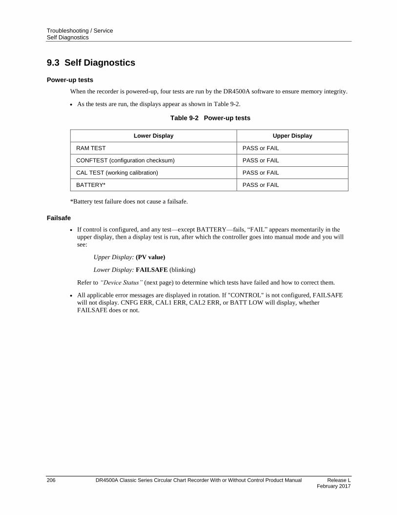
Troubleshooting / Service Self Diagnostics
206 DR4500A Classic Series Circular Chart Recorder With or Without Control Product Manual Release L February 2017
9.3 Self Diagnostics
Power-up tests
When the recorder is powered-up, four tests are run by the DR4500A software to ensure memory integrity.
As the tests are run, the displays appear as shown in Table 9-2.
Table 9-2 Power-up tests
Lower Display Upper Display
RAM TEST PASS or FAIL
CONFTEST (configuration checksum) PASS or FAIL
CAL TEST (working calibration) PASS or FAIL
BATTERY* PASS or FAIL
*Battery test failure does not cause a failsafe.
Failsafe
If control is configured, and any test—except BATTERY—fails, “FAIL” appears momentarily in the
upper display, then a display test is run, after which the controller goes into manual mode and you will
see:
Upper Display: (PV value)
Lower Display: FAILSAFE (blinking)
Refer to “Device Status” (next page) to determine which tests have failed and how to correct them.
All applicable error messages are displayed in rotation. If "CONTROL" is not configured, FAILSAFE
will not display. CNFG ERR, CAL1 ERR, CAL2 ERR, or BATT LOW will display, whether
FAILSAFE does or not.

Troubleshooting / Service Self Diagnostics
Release M DR4500A Classic Series Circular Chart Recorder With or Without Control Product Manual 207 April 2017
Device status
When required, the results of the power-up tests can be checked to determine the reason the recorder has
gone to “Failsafe”.
The following procedure in Table 9-3 tells you how to display the results of the latest tests run. Table 9-4
lists the tests, the reason for the failure, and how to correct the problem.
Table 9-3 Procedure for displaying the device status
Step Operation Press Action/Result
1 Select STATUS Set Up Group
SET UP
Until you see:
Upper Display: READ
Lower Display: STATUS
2 Read the status tests results
FUNC Until you see:
Upper Display: NO or YES
(YES indicates a failure)
Lower Display: FAILSAFE
Successive presses of the FUNC key will display the
results of the tests (PASS or FAIL) in the following order:
RAM TEST CONFTEST CAL TEST FACT CRC BATTERY
Identify the problem from the error message and correct the failure as shown under "Lower Display Indication” in Table 9-4.
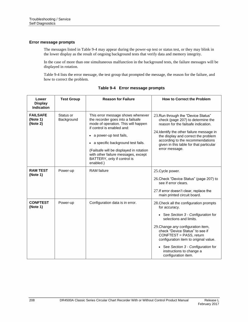
Troubleshooting / Service Self Diagnostics
208 DR4500A Classic Series Circular Chart Recorder With or Without Control Product Manual Release L February 2017
Error message prompts
The messages listed in Table 9-4 may appear during the power-up test or status test, or they may blink in
the lower display as the result of ongoing background tests that verify data and memory integrity.
In the case of more than one simultaneous malfunction in the background tests, the failure messages will be
displayed in rotation.
Table 9-4 lists the error message, the test group that prompted the message, the reason for the failure, and
how to correct the problem.
Table 9-4 Error message prompts
Lower Display
Indication
Test Group Reason for Failure How to Correct the Problem
FAILSAFE (Note 1) (Note 2)
Status or Background
This error message shows whenever the recorder goes into a failsafe mode of operation. This will happen if control is enabled and:
a power-up test fails,
a specific background test fails.
(Failsafe will be displayed in rotation with other failure messages, except BATTERY, only if control is enabled.)
23. Run through the “Device Status” check (page 207) to determine the reason for the failsafe indication.
24. Identify the other failure message in the display and correct the problem according to the recommendations given in this table for that particular error message.
RAM TEST (Note 1)
Power-up RAM failure 25. Cycle power.
26. Check “Device Status” (page 207) to see if error clears.
27. If error doesn’t clear, replace the main printed circuit board.
CONFTEST (Note 1)
Power-up Configuration data is in error. 28. Check all the configuration prompts for accuracy.
See Section 3 - Configuration for selections and limits.
29. Change any configuration item, check “Device Status” to see if CONFTEST = PASS, return configuration item to original value.
See Section 3 - Configuration for
instructions to change a configuration item.
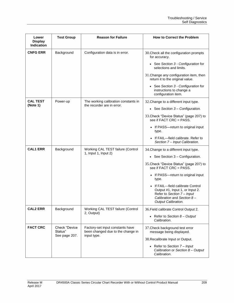
Troubleshooting / Service Self Diagnostics
Release M DR4500A Classic Series Circular Chart Recorder With or Without Control Product Manual 209 April 2017
Lower Display
Indication
Test Group Reason for Failure How to Correct the Problem
CNFG ERR Background Configuration data is in error. 30. Check all the configuration prompts for accuracy.
See Section 3 - Configuration for
selections and limits.
31. Change any configuration item, then return it to the original value.
See Section 3 - Configuration for
instructions to change a configuration item.
CAL TEST (Note 1)
Power-up The working calibration constants in the recorder are in error.
32. Change to a different input type.
See Section 3 – Configuration.
33. Check “Device Status” (page 207) to see if FACT CRC = PASS.
If PASS—return to original input type.
If FAIL—field calibrate. Refer to Section 7 – Input Calibration.
CAL1 ERR Background Working CAL TEST failure (Control 1, Input 1, Input 2)
34. Change to a different input type.
See Section 3 – Configuration.
35. Check “Device Status” (page 207) to see if FACT CRC = PASS.
If PASS—return to original input type.
If FAIL—field calibrate Control Output #1, Input 1, or Input 2. Refer to Section 7 – Input Calibration and Section 8 – Output Calibration.
CAL2 ERR Background Working CAL TEST failure (Control 2, Output)
36. Field calibrate Control Output 2.
Refer to Section 8 – Output Calibration.
FACT CRC Check “Device Status” See page 207.
Factory-set input constants have been changed due to the change in input type.
37. Check background test error message being displayed.
38. Recalibrate Input or Output.
Refer to Section 7 – Input Calibration or Section 8 – Output Calibration.
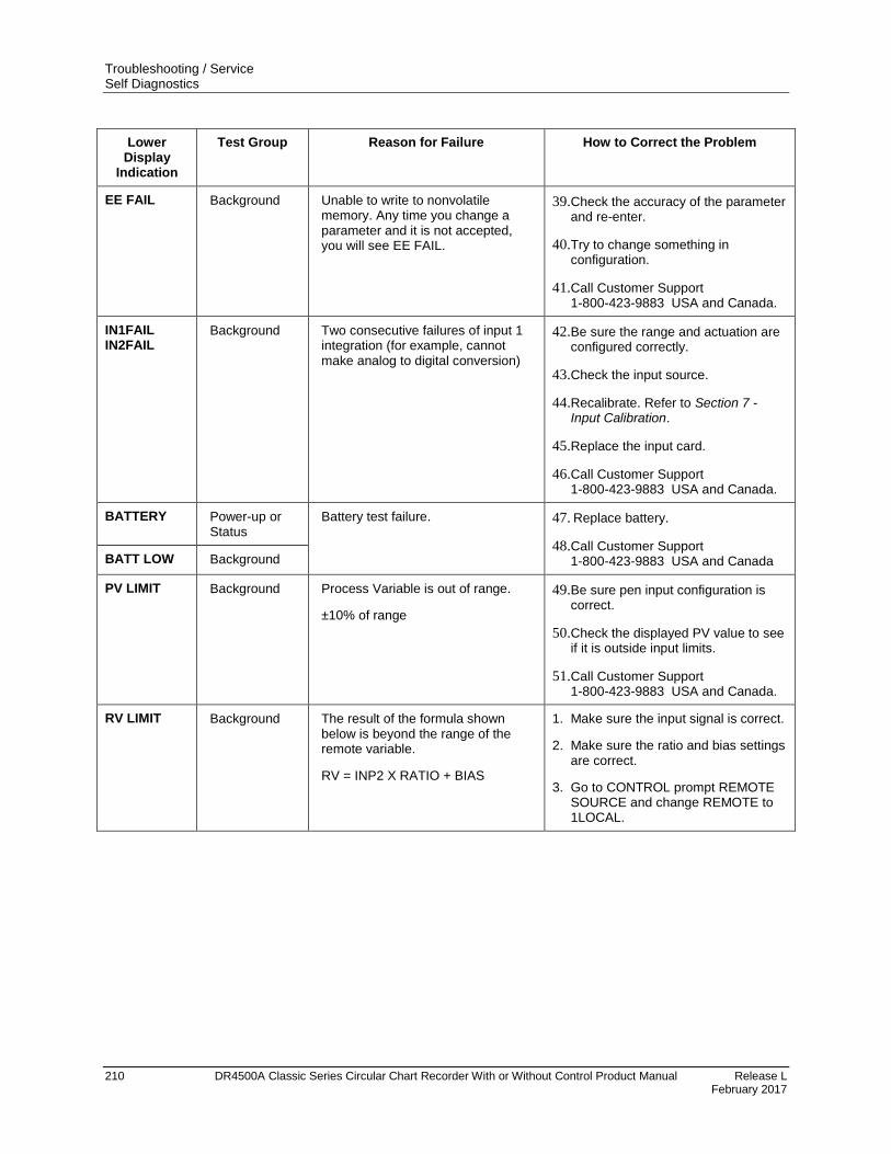
Troubleshooting / Service Self Diagnostics
210 DR4500A Classic Series Circular Chart Recorder With or Without Control Product Manual Release L February 2017
Lower Display
Indication
Test Group Reason for Failure How to Correct the Problem
EE FAIL Background Unable to write to nonvolatile memory. Any time you change a parameter and it is not accepted, you will see EE FAIL.
39. Check the accuracy of the parameter and re-enter.
40. Try to change something in configuration.
41. Call Customer Support 1-800-423-9883 USA and Canada.
IN1FAIL IN2FAIL
Background Two consecutive failures of input 1 integration (for example, cannot make analog to digital conversion)
42. Be sure the range and actuation are configured correctly.
43. Check the input source.
44. Recalibrate. Refer to Section 7 - Input Calibration.
45. Replace the input card.
46. Call Customer Support 1-800-423-9883 USA and Canada.
BATTERY Power-up or Status
Battery test failure. 47. Replace battery.
48. Call Customer Support 1-800-423-9883 USA and Canada BATT LOW Background
PV LIMIT Background Process Variable is out of range.
±10% of range
49. Be sure pen input configuration is correct.
50. Check the displayed PV value to see if it is outside input limits.
51. Call Customer Support 1-800-423-9883 USA and Canada.
RV LIMIT Background The result of the formula shown below is beyond the range of the remote variable.
RV = INP2 X RATIO + BIAS
1. Make sure the input signal is correct.
2. Make sure the ratio and bias settings are correct.
3. Go to CONTROL prompt REMOTE SOURCE and change REMOTE to 1LOCAL.
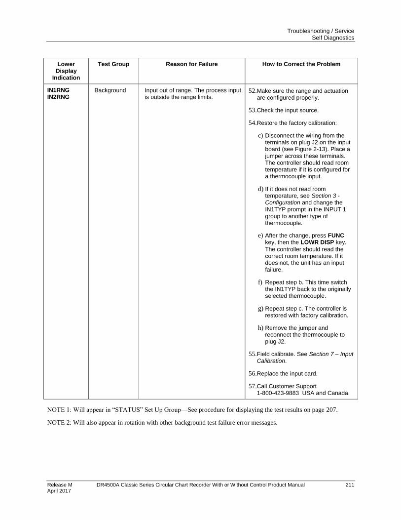
Troubleshooting / Service Self Diagnostics
Release M DR4500A Classic Series Circular Chart Recorder With or Without Control Product Manual 211 April 2017
Lower Display
Indication
Test Group Reason for Failure How to Correct the Problem
IN1RNG IN2RNG
Background Input out of range. The process input is outside the range limits.
52. Make sure the range and actuation are configured properly.
53. Check the input source.
54. Restore the factory calibration:
c) Disconnect the wiring from the terminals on plug J2 on the input board (see Figure 2-13). Place a jumper across these terminals. The controller should read room temperature if it is configured for a thermocouple input.
d) If it does not read room temperature, see Section 3 - Configuration and change the IN1TYP prompt in the INPUT 1 group to another type of thermocouple.
e) After the change, press FUNC key, then the LOWR DISP key.
The controller should read the correct room temperature. If it does not, the unit has an input failure.
f) Repeat step b. This time switch the IN1TYP back to the originally selected thermocouple.
g) Repeat step c. The controller is restored with factory calibration.
h) Remove the jumper and reconnect the thermocouple to plug J2.
55. Field calibrate. See Section 7 – Input Calibration.
56. Replace the input card.
57. Call Customer Support 1-800-423-9883 USA and Canada.
NOTE 1: Will appear in “STATUS” Set Up Group—See procedure for displaying the test results on page 207.
NOTE 2: Will also appear in rotation with other background test failure error messages.
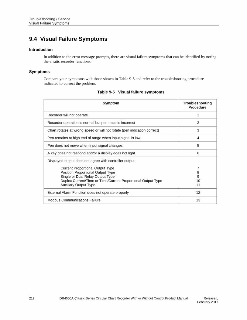
Troubleshooting / Service Visual Failure Symptoms
212 DR4500A Classic Series Circular Chart Recorder With or Without Control Product Manual Release L February 2017
9.4 Visual Failure Symptoms
Introduction
In addition to the error message prompts, there are visual failure symptoms that can be identified by noting
the erratic recorder functions.
Symptoms
Compare your symptoms with those shown in Table 9-5 and refer to the troubleshooting procedure
indicated to correct the problem.
Table 9-5 Visual failure symptoms
Symptom Troubleshooting Procedure
Recorder will not operate 1
Recorder operation is normal but pen trace is incorrect 2
Chart rotates at wrong speed or will not rotate (pen indication correct) 3
Pen remains at high end of range when input signal is low 4
Pen does not move when input signal changes 5
A key does not respond and/or a display does not light 6
Displayed output does not agree with controller output
Current Proportional Output Type Position Proportional Output Type Single or Dual Relay Output Type Duplex Current/Time or Time/Current Proportional Output Type Auxiliary Output Type
7 8 9
10 11
External Alarm Function does not operate properly 12
Modbus Communications Failure 13
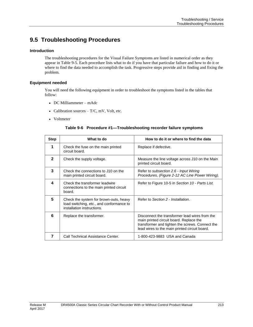
Troubleshooting / Service Troubleshooting Procedures
Release M DR4500A Classic Series Circular Chart Recorder With or Without Control Product Manual 213 April 2017
9.5 Troubleshooting Procedures
Introduction
The troubleshooting procedures for the Visual Failure Symptoms are listed in numerical order as they
appear in Table 9-5. Each procedure lists what to do if you have that particular failure and how to do it or
where to find the data needed to accomplish the task. Progressive steps provide aid in finding and fixing the
problem.
Equipment needed
You will need the following equipment in order to troubleshoot the symptoms listed in the tables that
follow:
DC Milliammeter – mAdc
Calibration sources – T/C, mV, Volt, etc.
Voltmeter
Table 9-6 Procedure #1—Troubleshooting recorder failure symptoms
Step What to do How to do it or where to find the data
1 Check the fuse on the main printed circuit board.
Replace if defective.
2 Check the supply voltage. Measure the line voltage across J10 on the Main printed circuit board.
3 Check the connections to J10 on the main printed circuit board.
Refer to subsection 2.6 - Input Wiring Procedures, (Figure 2-12 AC Line Power Wiring).
4 Check the transformer leadwire connections to the main printed circuit board.
Refer to Figure 10-5 in Section 10 - Parts List.
5 Check the system for brown-outs, heavy load switching, etc., and conformance to installation instructions.
Refer to Section 2 - Installation.
6 Replace the transformer. Disconnect the transformer lead wires from the main printed circuit board. Replace the transformer and tighten the screws. Connect the lead wires to the main printed circuit board.
7 Call Technical Assistance Center. 1-800-423-9883 USA and Canada
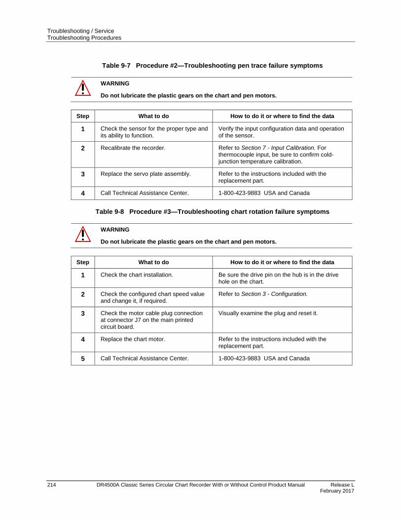
Troubleshooting / Service Troubleshooting Procedures
214 DR4500A Classic Series Circular Chart Recorder With or Without Control Product Manual Release L February 2017
Table 9-7 Procedure #2—Troubleshooting pen trace failure symptoms
WARNING
Do not lubricate the plastic gears on the chart and pen motors.
Step What to do How to do it or where to find the data
1 Check the sensor for the proper type and its ability to function.
Verify the input configuration data and operation of the sensor.
2 Recalibrate the recorder. Refer to Section 7 - Input Calibration. For thermocouple input, be sure to confirm cold-junction temperature calibration.
3 Replace the servo plate assembly. Refer to the instructions included with the replacement part.
4 Call Technical Assistance Center. 1-800-423-9883 USA and Canada
Table 9-8 Procedure #3—Troubleshooting chart rotation failure symptoms
WARNING
Do not lubricate the plastic gears on the chart and pen motors.
Step What to do How to do it or where to find the data
1 Check the chart installation. Be sure the drive pin on the hub is in the drive hole on the chart.
2 Check the configured chart speed value and change it, if required.
Refer to Section 3 - Configuration.
3 Check the motor cable plug connection at connector J7 on the main printed circuit board.
Visually examine the plug and reset it.
4 Replace the chart motor. Refer to the instructions included with the replacement part.
5 Call Technical Assistance Center. 1-800-423-9883 USA and Canada
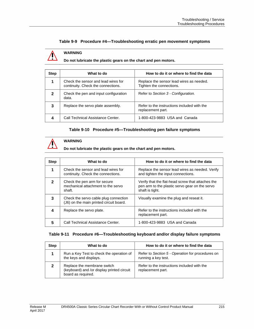
Troubleshooting / Service Troubleshooting Procedures
Release M DR4500A Classic Series Circular Chart Recorder With or Without Control Product Manual 215 April 2017
Table 9-9 Procedure #4—Troubleshooting erratic pen movement symptoms
WARNING
Do not lubricate the plastic gears on the chart and pen motors.
Step What to do How to do it or where to find the data
1 Check the sensor and lead wires for continuity. Check the connections.
Replace the sensor lead wires as needed. Tighten the connections.
2 Check the pen and input configuration data.
Refer to Section 3 - Configuration.
3 Replace the servo plate assembly. Refer to the instructions included with the replacement part.
4 Call Technical Assistance Center. 1-800-423-9883 USA and Canada
Table 9-10 Procedure #5—Troubleshooting pen failure symptoms
WARNING
Do not lubricate the plastic gears on the chart and pen motors.
Step What to do How to do it or where to find the data
1 Check the sensor and lead wires for continuity. Check the connections.
Replace the sensor lead wires as needed. Verify and tighten the input connections.
2 Check the pen arm for secure mechanical attachment to the servo shaft.
Verify that the flat-head screw that attaches the pen arm to the plastic servo gear on the servo shaft is tight.
3 Check the servo cable plug connection (J6) on the main printed circuit board.
Visually examine the plug and reseat it.
4 Replace the servo plate. Refer to the instructions included with the replacement part.
5 Call Technical Assistance Center. 1-800-423-9883 USA and Canada
Table 9-11 Procedure #6—Troubleshooting keyboard and/or display failure symptoms
Step What to do How to do it or where to find the data
1 Run a Key Test to check the operation of the keys and displays.
Refer to Section 5 - Operation for procedures on
running a key test.
2 Replace the membrane switch (keyboard) and /or display printed circuit board as required.
Refer to the instructions included with the replacement part.
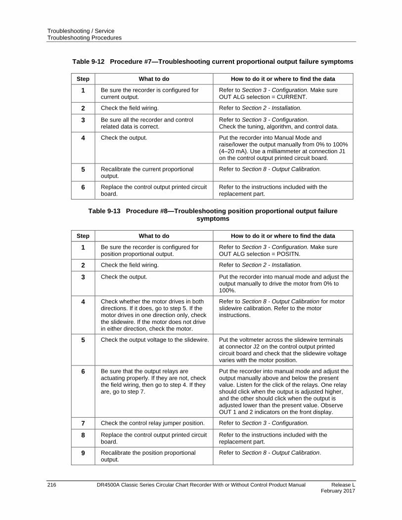
Troubleshooting / Service Troubleshooting Procedures
216 DR4500A Classic Series Circular Chart Recorder With or Without Control Product Manual Release L February 2017
Table 9-12 Procedure #7—Troubleshooting current proportional output failure symptoms
Step What to do How to do it or where to find the data
1 Be sure the recorder is configured for current output.
Refer to Section 3 - Configuration. Make sure
OUT ALG selection = CURRENT.
2 Check the field wiring. Refer to Section 2 - Installation.
3 Be sure all the recorder and control related data is correct.
Refer to Section 3 - Configuration. Check the tuning, algorithm, and control data.
4 Check the output. Put the recorder into Manual Mode and raise/lower the output manually from 0% to 100% (4–20 mA). Use a milliammeter at connection J1 on the control output printed circuit board.
5 Recalibrate the current proportional output.
Refer to Section 8 - Output Calibration.
6 Replace the control output printed circuit board.
Refer to the instructions included with the replacement part.
Table 9-13 Procedure #8—Troubleshooting position proportional output failure symptoms
Step What to do How to do it or where to find the data
1 Be sure the recorder is configured for position proportional output.
Refer to Section 3 - Configuration. Make sure
OUT ALG selection = POSITN.
2 Check the field wiring. Refer to Section 2 - Installation.
3 Check the output. Put the recorder into manual mode and adjust the output manually to drive the motor from 0% to 100%.
4 Check whether the motor drives in both directions. If it does, go to step 5. If the motor drives in one direction only, check the slidewire. If the motor does not drive in either direction, check the motor.
Refer to Section 8 - Output Calibration for motor slidewire calibration. Refer to the motor instructions.
5 Check the output voltage to the slidewire. Put the voltmeter across the slidewire terminals at connector J2 on the control output printed circuit board and check that the slidewire voltage varies with the motor position.
6 Be sure that the output relays are actuating properly. If they are not, check the field wiring, then go to step 4. If they are, go to step 7.
Put the recorder into manual mode and adjust the output manually above and below the present value. Listen for the click of the relays. One relay should click when the output is adjusted higher, and the other should click when the output is adjusted lower than the present value. Observe OUT 1 and 2 indicators on the front display.
7 Check the control relay jumper position. Refer to Section 3 - Configuration.
8 Replace the control output printed circuit board.
Refer to the instructions included with the replacement part.
9 Recalibrate the position proportional output.
Refer to Section 8 - Output Calibration.
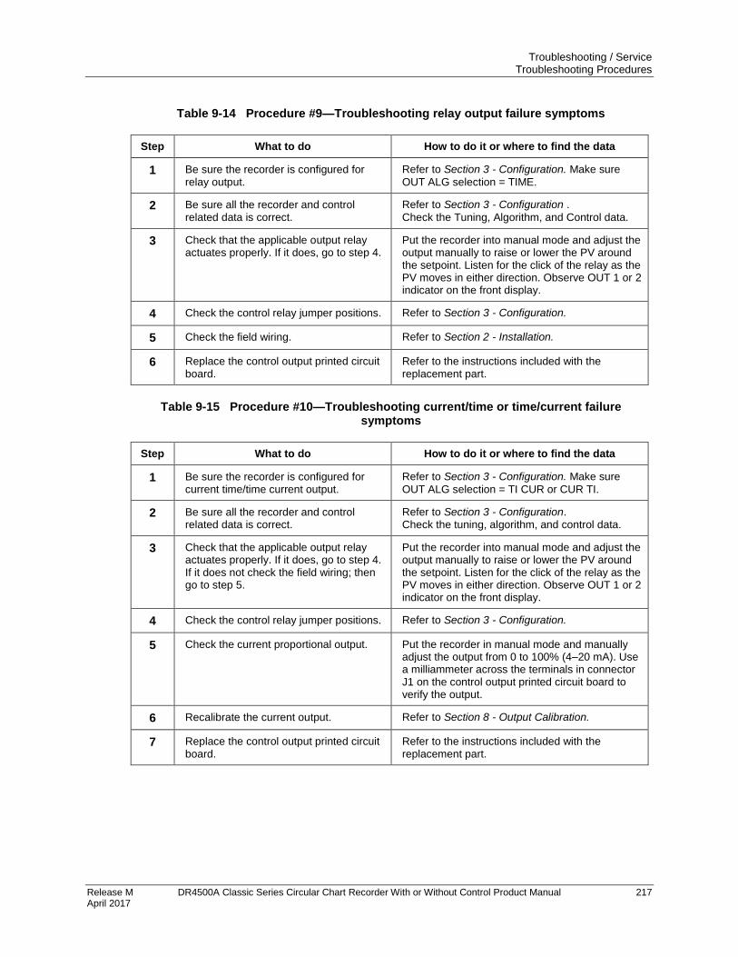
Troubleshooting / Service Troubleshooting Procedures
Release M DR4500A Classic Series Circular Chart Recorder With or Without Control Product Manual 217 April 2017
Table 9-14 Procedure #9—Troubleshooting relay output failure symptoms
Step What to do How to do it or where to find the data
1 Be sure the recorder is configured for relay output.
Refer to Section 3 - Configuration. Make sure
OUT ALG selection = TIME.
2 Be sure all the recorder and control related data is correct.
Refer to Section 3 - Configuration .
Check the Tuning, Algorithm, and Control data.
3 Check that the applicable output relay actuates properly. If it does, go to step 4.
Put the recorder into manual mode and adjust the output manually to raise or lower the PV around the setpoint. Listen for the click of the relay as the PV moves in either direction. Observe OUT 1 or 2 indicator on the front display.
4 Check the control relay jumper positions. Refer to Section 3 - Configuration.
5 Check the field wiring. Refer to Section 2 - Installation.
6 Replace the control output printed circuit board.
Refer to the instructions included with the replacement part.
Table 9-15 Procedure #10—Troubleshooting current/time or time/current failure symptoms
Step What to do How to do it or where to find the data
1 Be sure the recorder is configured for current time/time current output.
Refer to Section 3 - Configuration. Make sure
OUT ALG selection = TI CUR or CUR TI.
2 Be sure all the recorder and control related data is correct.
Refer to Section 3 - Configuration. Check the tuning, algorithm, and control data.
3 Check that the applicable output relay actuates properly. If it does, go to step 4. If it does not check the field wiring; then go to step 5.
Put the recorder into manual mode and adjust the output manually to raise or lower the PV around the setpoint. Listen for the click of the relay as the PV moves in either direction. Observe OUT 1 or 2 indicator on the front display.
4 Check the control relay jumper positions. Refer to Section 3 - Configuration.
5 Check the current proportional output. Put the recorder in manual mode and manually adjust the output from 0 to 100% (4–20 mA). Use a milliammeter across the terminals in connector J1 on the control output printed circuit board to verify the output.
6 Recalibrate the current output. Refer to Section 8 - Output Calibration.
7 Replace the control output printed circuit board.
Refer to the instructions included with the replacement part.
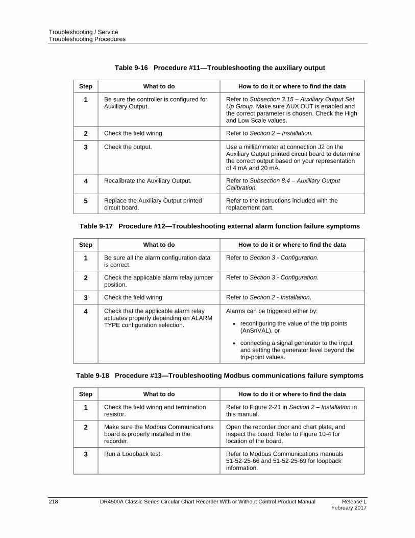
Troubleshooting / Service Troubleshooting Procedures
218 DR4500A Classic Series Circular Chart Recorder With or Without Control Product Manual Release L February 2017
Table 9-16 Procedure #11—Troubleshooting the auxiliary output
Step What to do How to do it or where to find the data
1 Be sure the controller is configured for Auxiliary Output.
Refer to Subsection 3.15 – Auxiliary Output Set Up Group. Make sure AUX OUT is enabled and the correct parameter is chosen. Check the High and Low Scale values.
2 Check the field wiring. Refer to Section 2 – Installation.
3 Check the output. Use a milliammeter at connection J2 on the Auxiliary Output printed circuit board to determine the correct output based on your representation of 4 mA and 20 mA.
4 Recalibrate the Auxiliary Output. Refer to Subsection 8.4 – Auxiliary Output Calibration.
5 Replace the Auxiliary Output printed circuit board.
Refer to the instructions included with the replacement part.
Table 9-17 Procedure #12—Troubleshooting external alarm function failure symptoms
Step What to do How to do it or where to find the data
1 Be sure all the alarm configuration data is correct.
Refer to Section 3 - Configuration.
2 Check the applicable alarm relay jumper position.
Refer to Section 3 - Configuration.
3 Check the field wiring. Refer to Section 2 - Installation.
4 Check that the applicable alarm relay actuates properly depending on ALARM TYPE configuration selection.
Alarms can be triggered either by:
reconfiguring the value of the trip points (AnSnVAL), or
connecting a signal generator to the input and setting the generator level beyond the trip-point values.
Table 9-18 Procedure #13—Troubleshooting Modbus communications failure symptoms
Step What to do How to do it or where to find the data
1 Check the field wiring and termination resistor.
Refer to Figure 2-21 in Section 2 – Installation in
this manual.
2 Make sure the Modbus Communications board is properly installed in the recorder.
Open the recorder door and chart plate, and inspect the board. Refer to Figure 10-4 for location of the board.
3 Run a Loopback test. Refer to Modbus Communications manuals 51-52-25-66 and 51-52-25-69 for loopback information.
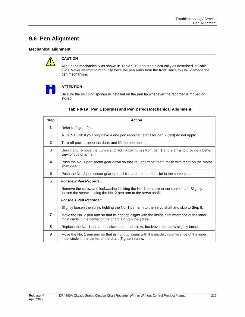
Troubleshooting / Service Pen Alignment
Release M DR4500A Classic Series Circular Chart Recorder With or Without Control Product Manual 219 April 2017
9.6 Pen Alignment
Mechanical alignment
CAUTION
Align pens mechanically as shown in Table 9-19 and then electrically as described in Table 9-20. Never attempt to manually force the pen arms from the front, since this will damage the pen mechanism.
ATTENTION
Be sure the shipping sponge is installed on the pen tip whenever the recorder is moved or stored.
Table 9-19 Pen 1 (purple) and Pen 2 (red) Mechanical Alignment
Step Action
1 Refer to Figure 9-1.
ATTENTION: If you only have a one pen recorder, steps for pen 2 (red) do not apply.
2 Turn off power, open the door, and lift the pen lifter up.
3 Unclip and remove the purple and red ink cartridges from pen 1 and 2 arms to provide a better view of tips of arms.
4 Push the No. 1 pen sector gear down so that its uppermost teeth mesh with teeth on the motor shaft gear.
5 Push the No. 2 pen sector gear up until it is at the top of the slot in the servo plate.
6 For the 2 Pen Recorder:
Remove the screw and lockwasher holding the No. 1 pen arm to the servo shaft. Slightly loosen the screw holding the No. 2 pen arm to the servo shaft.
For the 1 Pen Recorder:
Slightly loosen the screw holding the No. 1 pen arm to the servo shaft and skip to Step 8.
7 Move the No. 2 pen arm so that its right tip aligns with the inside circumference of the inner most circle in the center of the chart. Tighten the screw.
8 Replace the No. 1 pen arm, lockwasher, and screw, but leave the screw slightly loose.
9 Move the No. 1 pen arm so that its right tip aligns with the inside circumference of the inner most circle in the center of the chart. Tighten screw.
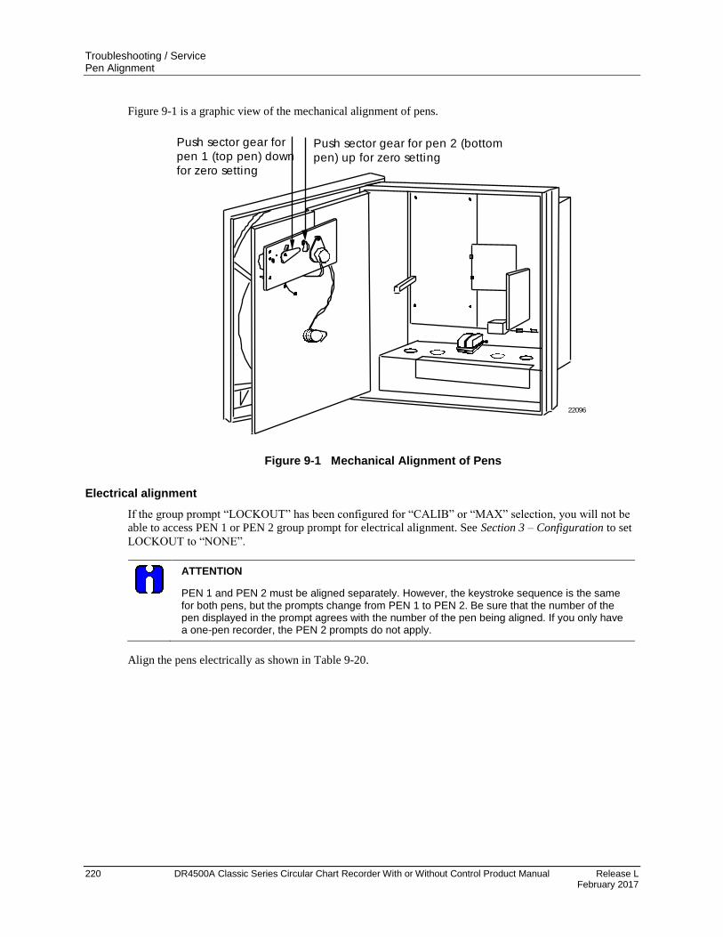
Troubleshooting / Service Pen Alignment
220 DR4500A Classic Series Circular Chart Recorder With or Without Control Product Manual Release L February 2017
Figure 9-1 is a graphic view of the mechanical alignment of pens.
Push sector gear for
pen 1 (top pen) down
for zero setting
Push sector gear for pen 2 (bottom
pen) up for zero setting
22096
Figure 9-1 Mechanical Alignment of Pens
Electrical alignment
If the group prompt “LOCKOUT” has been configured for “CALIB” or “MAX” selection, you will not be
able to access PEN 1 or PEN 2 group prompt for electrical alignment. See Section 3 – Configuration to set
LOCKOUT to “NONE”.
ATTENTION
PEN 1 and PEN 2 must be aligned separately. However, the keystroke sequence is the same for both pens, but the prompts change from PEN 1 to PEN 2. Be sure that the number of the pen displayed in the prompt agrees with the number of the pen being aligned. If you only have a one-pen recorder, the PEN 2 prompts do not apply.
Align the pens electrically as shown in Table 9-20.

Troubleshooting / Service Pen Alignment
Release M DR4500A Classic Series Circular Chart Recorder With or Without Control Product Manual 221 April 2017
Table 9-20 Set the chart time line procedure
Step Press Action/Result
1 Open the door, apply power, and wait for the recorder to run its power up tests.
2 SET UP
Until you see:
Upper Display: ALIGN
Lower Display: PEN 1
3 FUNC You will see:
Upper Display: ALIGN
Lower Display: PEN 10
The pen moves to an internal stop then backs away and stops.
or To move the pen to the zero position on the chart (inner position of chart).
ATTENTION: You can position the pen over 100 steps. Those steps are relative units only. Step 0.0 is the innermost position on the chart, and step 1200 is the highest circumference position.
4 FUNC You will see:
Upper Display: ALIGN
Lower Display: PEN 100
The value adjusted in Step 3 is entered into memory.
or To raise or lower the value in the upper display (up to 1200) move the pen to the highest chart range value (outer circumference printed on the chart).
5 Repeat steps 2 through 4 for pen 2 or press LOWR DISP key to return to
normal operation and enter the span value into memory.

Parts List Overview
222 DR4500A Classic Series Circular Chart Recorder With or Without Control Product Manual Release L February 2017
10. Parts List
10.1 Overview
Introduction
This section provides the replacement parts lists for the DR4500A Clasic Series Recorder. Most parts are
supplied on an optimum replacement unit basis; that is, part numbers are given for complete printed circuit
boards rather than for individual PCB components.
The figures that follow are exploded views of the DR4500A recorder. Each part is labeled with a key
number and the key numbers are listed in tables with associated part number.
Also included for your reference are an Internal Cabling drawing (Figure 10-5) and an Internal Wiring
Diagram (Figure 10-6) for options only.
When ordering parts, be sure to specify your recorder’s serial and model numbers (on nameplate) as well as
the part identification.
What’s in this section?
This section contains the following topics:
Topic See Page
10.1 Overview 222
10.2 Exploded Views Figure 10-1 Door assembly Figure 10-2 Chart plate assembly Figure 10-3 Basic recorder components without options Figure 10-4 Recorder components associated with options
223 223 224 226 228
10.3 Miscellaneous Hardware Kit Contents 230
10.4 Figure 10-5 Internal Cabling Data 232
10.5 Figure 10-6 Internal Wiring Diagram – Options Only 233
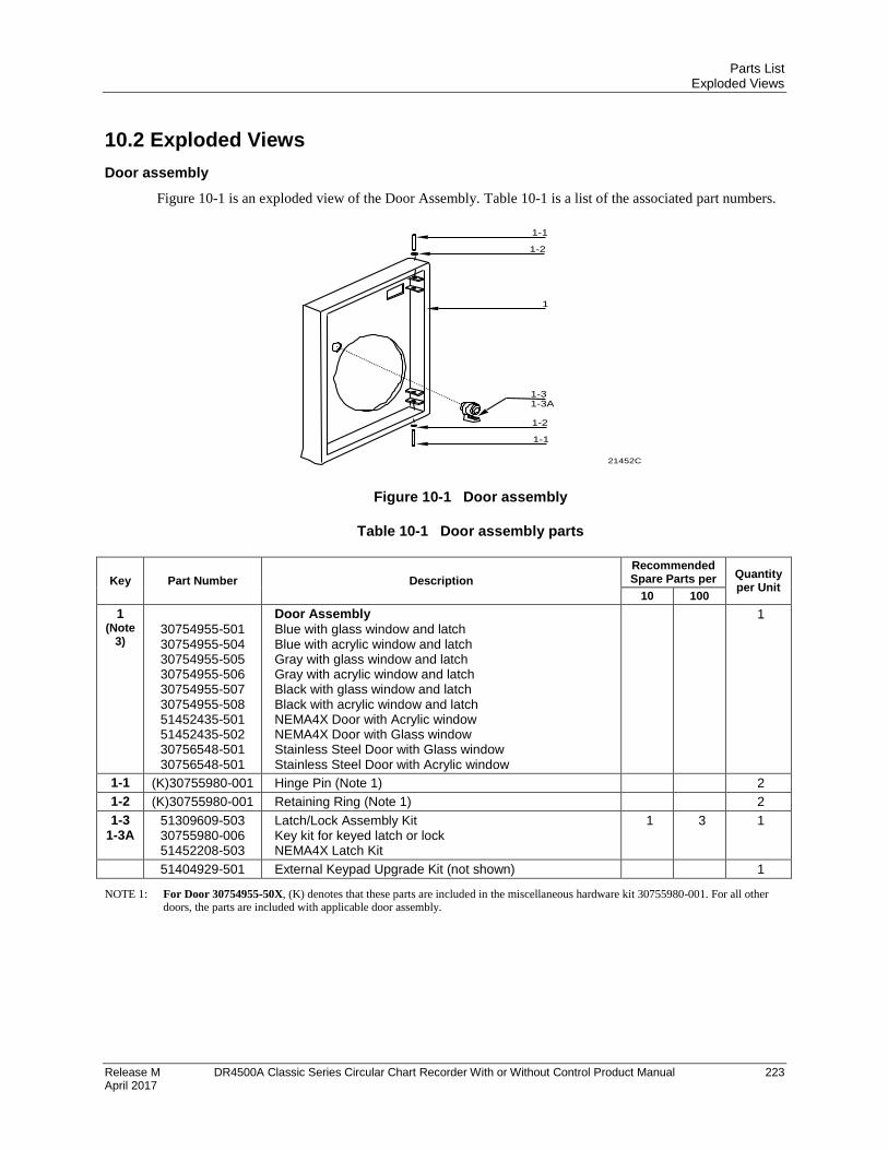
Parts List Exploded Views
Release M DR4500A Classic Series Circular Chart Recorder With or Without Control Product Manual 223 April 2017
10.2 Exploded Views
Door assembly
Figure 10-1 is an exploded view of the Door Assembly. Table 10-1 is a list of the associated part numbers.
1-1
21452C
1-2
1
1-3
1-1
1-2
1-3A
Figure 10-1 Door assembly
Table 10-1 Door assembly parts
Key Part Number Description
Recommended Spare Parts per Quantity
per Unit 10 100
1 (Note
3)
30754955-501 30754955-504 30754955-505 30754955-506 30754955-507 30754955-508 51452435-501 51452435-502 30756548-501 30756548-501
Door Assembly
Blue with glass window and latch Blue with acrylic window and latch Gray with glass window and latch Gray with acrylic window and latch Black with glass window and latch Black with acrylic window and latch NEMA4X Door with Acrylic window NEMA4X Door with Glass window Stainless Steel Door with Glass window Stainless Steel Door with Acrylic window
1
1-1 (K)30755980-001 Hinge Pin (Note 1) 2
1-2 (K)30755980-001 Retaining Ring (Note 1) 2
1-3 1-3A
51309609-503 30755980-006 51452208-503
Latch/Lock Assembly Kit Key kit for keyed latch or lock NEMA4X Latch Kit
1 3 1
51404929-501 External Keypad Upgrade Kit (not shown) 1 NOTE 1: For Door 30754955-50X, (K) denotes that these parts are included in the miscellaneous hardware kit 30755980-001. For all other
doors, the parts are included with applicable door assembly.

Parts List Exploded Views
224 DR4500A Classic Series Circular Chart Recorder With or Without Control Product Manual Release L February 2017
Chart plate
Figure 10-2 is an exploded view of the Chart Plate Assembly.
Table 10-2 is a list of the associated part numbers.
12 11
789
1 3
22097
4
2
5
6
10
13
Figure 10-2 Chart plate assembly
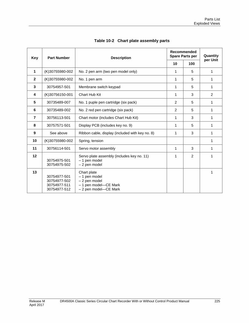
Parts List Exploded Views
Release M DR4500A Classic Series Circular Chart Recorder With or Without Control Product Manual 225 April 2017
Table 10-2 Chart plate assembly parts
Key Part Number Description
Recommended Spare Parts per Quantity
per Unit 10 100
1 (K)30755980-002 No. 2 pen arm (two pen model only) 1 5 1
2 (K)30755980-002 No. 1 pen arm 1 5 1
3 30754957-501 Membrane switch keypad 1 5 1
4 (K)30756150-001 Chart Hub Kit 1 3 2
5 30735489-007 No. 1 puple pen cartridge (six pack) 2 5 1
6 30735489-002 No. 2 red pen cartridge (six pack) 2 5 1
7 30756113-501 Chart motor (includes Chart Hub Kit) 1 3 1
8 30757571-501 Display PCB (includes key no. 9) 1 5 1
9 See above Ribbon cable, display (included with key no. 8) 1 3 1
10 (K)30755980-002 Spring, tension 1
11 30756114-501 Servo motor assembly 1 3 1
12 30754975-501 30754975-502
Servo plate assembly (includes key no. 11) – 1 pen model – 2 pen model
1 2 1
13 30754977-501 30754977-502 30754977-511 30754977-512
Chart plate – 1 pen model – 2 pen model – 1 pen model—CE Mark – 2 pen model—CE Mark
1
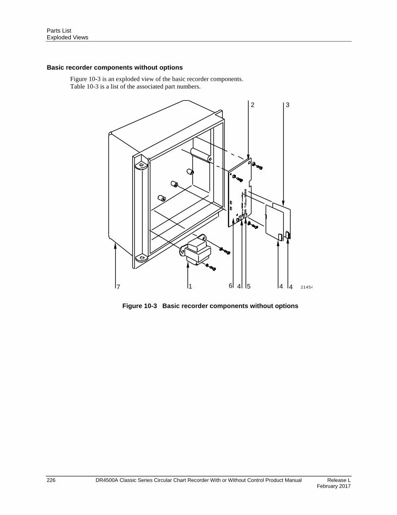
Parts List Exploded Views
226 DR4500A Classic Series Circular Chart Recorder With or Without Control Product Manual Release L February 2017
Basic recorder components without options
Figure 10-3 is an exploded view of the basic recorder components.
Table 10-3 is a list of the associated part numbers.
1 4 5 4
32
7 46 21454
Figure 10-3 Basic recorder components without options
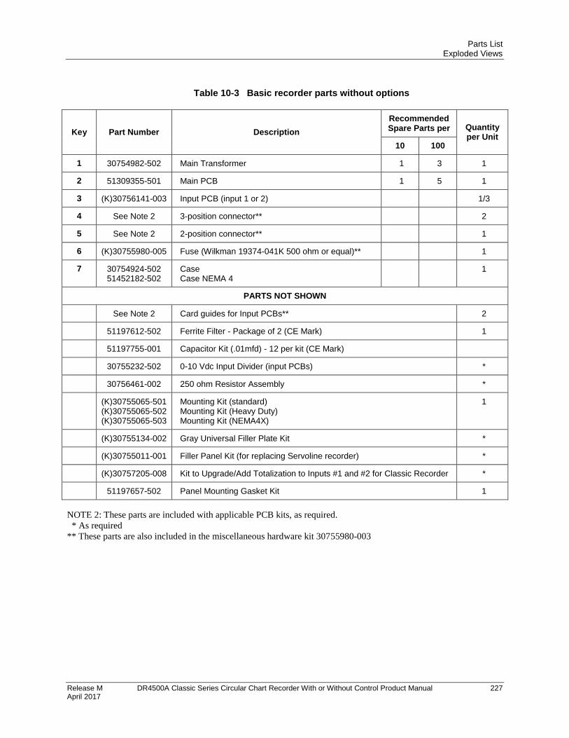
Parts List Exploded Views
Release M DR4500A Classic Series Circular Chart Recorder With or Without Control Product Manual 227 April 2017
Table 10-3 Basic recorder parts without options
Key Part Number Description
Recommended Spare Parts per Quantity
per Unit 10 100
1 30754982-502 Main Transformer 1 3 1
2 51309355-501 Main PCB 1 5 1
3 (K)30756141-003 Input PCB (input 1 or 2) 1/3
4 See Note 2 3-position connector** 2
5 See Note 2 2-position connector** 1
6 (K)30755980-005 Fuse (Wilkman 19374-041K 500 ohm or equal)** 1
7 30754924-502 51452182-502
Case Case NEMA 4
1
PARTS NOT SHOWN
See Note 2 Card guides for Input PCBs** 2
51197612-502 Ferrite Filter - Package of 2 (CE Mark) 1
51197755-001 Capacitor Kit (.01mfd) - 12 per kit (CE Mark)
30755232-502 0-10 Vdc Input Divider (input PCBs) *
30756461-002 250 ohm Resistor Assembly *
(K)30755065-501 (K)30755065-502 (K)30755065-503
Mounting Kit (standard) Mounting Kit (Heavy Duty) Mounting Kit (NEMA4X)
1
(K)30755134-002 Gray Universal Filler Plate Kit *
(K)30755011-001 Filler Panel Kit (for replacing Servoline recorder) *
(K)30757205-008 Kit to Upgrade/Add Totalization to Inputs #1 and #2 for Classic Recorder *
51197657-502 Panel Mounting Gasket Kit 1
NOTE 2: These parts are included with applicable PCB kits, as required.
* As required
** These parts are also included in the miscellaneous hardware kit 30755980-003
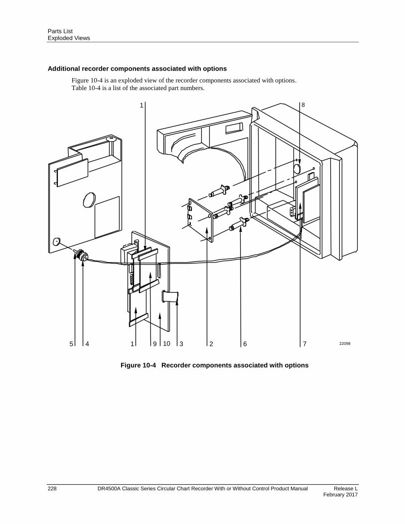
Parts List Exploded Views
228 DR4500A Classic Series Circular Chart Recorder With or Without Control Product Manual Release L February 2017
Additional recorder components associated with options
Figure 10-4 is an exploded view of the recorder components associated with options.
Table 10-4 is a list of the associated part numbers.
5 4 3 2 6 7
1 8
220981 9 10
Figure 10-4 Recorder components associated with options
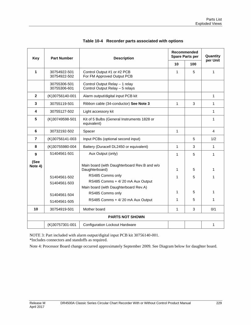
Parts List Exploded Views
Release M DR4500A Classic Series Circular Chart Recorder With or Without Control Product Manual 229 April 2017
Table 10-4 Recorder parts associated with options
Key Part Number Description
Recommended Spare Parts per Quantity
per Unit 10 100
1 30754922-501 30754922-502
Control Output #1 or #2 PCB For FM Approved Output PCB
1 5 1
30755306-501 30755306-601
Control Output Relay – 1 relay Control Output Relay – 5 relays
2 (K)30756140-001 Alarm output/digital input PCB kit 1
3 30755119-501 Ribbon cable (34-conductor) See Note 3 1 3 1
4 30755127-502 Light accessory kit 1
5 (K)30749598-501 Kit of 5 Bulbs (General Instruments 1828 or equivalent)
1
6 30732192-502 Spacer 1 4
7 (K)30756141-003 Input PCBs (optional second input) 5 1/2
8 (K)30755980-004 Battery (Duracell DL2450 or equivalent) 1 3 1
9
(See Note 4)
51404561-501
51404561-502
51404561-503
51404561-504
51404561-505
Aux Output (only)
Main board (with Daughterboard Rev.B and w/o Daughterboard)
RS485 Comms only
RS485 Comms + 4/ 20 mA Aux Output
Main board (with Daughterboard Rev.A)
RS485 Comms only
RS485 Comms + 4/ 20 mA Aux Output
1
1
1
1
1
5
5
5
5
5
1
1
1
1
1
10 30754919-501 Mother board 1 3 0/1
PARTS NOT SHOWN
(K)30757301-001 Configuration Lockout Hardware 1
NOTE 3: Part included with alarm output/digital input PCB kit 30756140-001.
*Includes connectors and standoffs as required.
Note 4: Processor Board change occurred approximately September 2009. See Diagram below for daughter board.
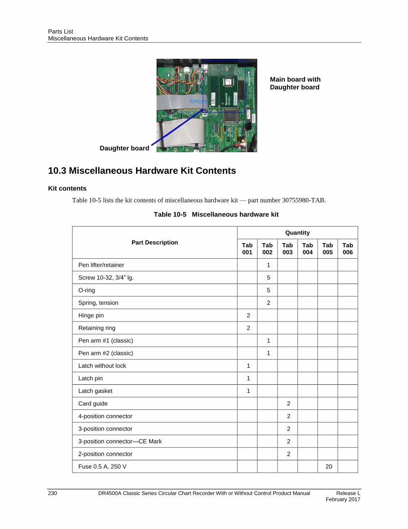
Parts List Miscellaneous Hardware Kit Contents
230 DR4500A Classic Series Circular Chart Recorder With or Without Control Product Manual Release L February 2017
10.3 Miscellaneous Hardware Kit Contents
Kit contents
Table 10-5 lists the kit contents of miscellaneous hardware kit — part number 30755980-TAB.
Table 10-5 Miscellaneous hardware kit
Part Description
Quantity
Tab 001
Tab 002
Tab 003
Tab 004
Tab 005
Tab 006
Pen lifter/retainer 1
Screw 10-32, 3/4” lg. 5
O-ring 5
Spring, tension 2
Hinge pin 2
Retaining ring 2
Pen arm #1 (classic) 1
Pen arm #2 (classic) 1
Latch without lock 1
Latch pin 1
Latch gasket 1
Card guide 2
4-position connector 2
3-position connector 2
3-position connector—CE Mark 2
2-position connector 2
Fuse 0.5 A, 250 V 20
Main board with Daughter board
Daughter board
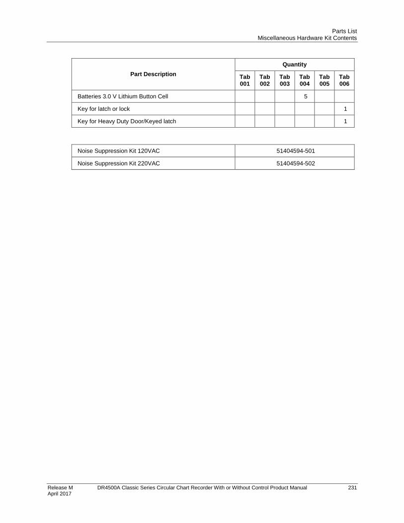
Parts List Miscellaneous Hardware Kit Contents
Release M DR4500A Classic Series Circular Chart Recorder With or Without Control Product Manual 231 April 2017
Part Description
Quantity
Tab 001
Tab 002
Tab 003
Tab 004
Tab 005
Tab 006
Batteries 3.0 V Lithium Button Cell 5
Key for latch or lock 1
Key for Heavy Duty Door/Keyed latch 1
Noise Suppression Kit 120VAC 51404594-501
Noise Suppression Kit 220VAC 51404594-502
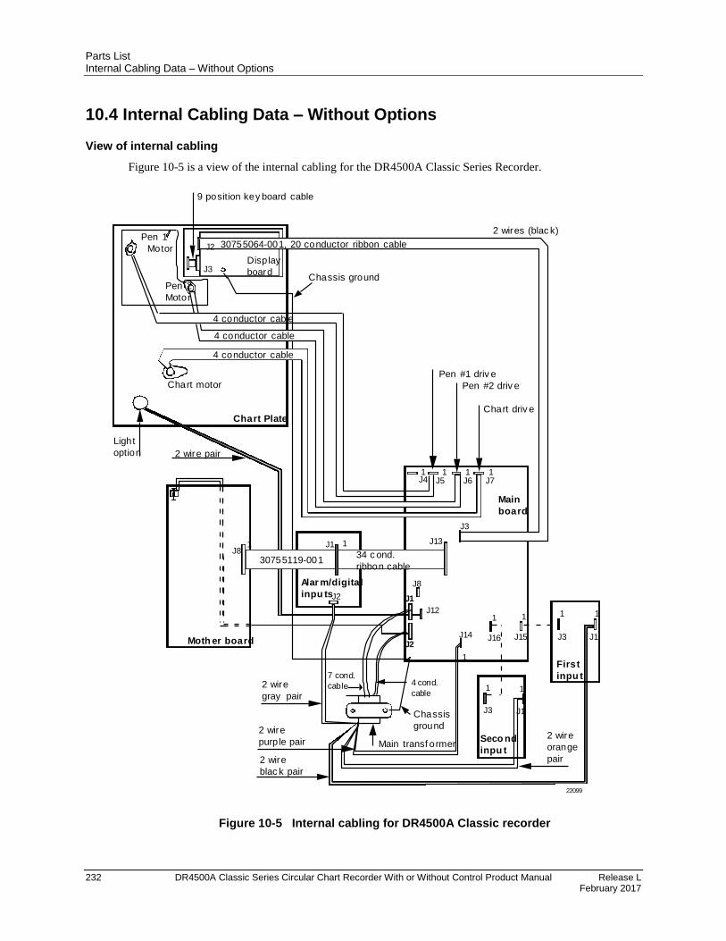
Parts List Internal Cabling Data – Without Options
232 DR4500A Classic Series Circular Chart Recorder With or Without Control Product Manual Release L February 2017
10.4 Internal Cabling Data – Without Options
View of internal cabling
Figure 10-5 is a view of the internal cabling for the DR4500A Classic Series Recorder.
Moth er board
J81 J13
J14
1
Chassis
ground
1
J16 J15
Main
board
J4 J7
J3
Alar m/digital
inpu tsJ2
J1 1
34 c ond.
ribbon cable30755119-001
J8
Chart Plate
Display
board
30755064-001, 20 conductor ribbon cable
4 conductor cable
4 conductor cable
4 conductor cable
2 wires (blac k)
Chassis groundPen 2
Motor
Chart motor
J5 J6
Pen #2 driv e
Chart driv e
1 1 1
Main transf ormer
9 position key board cable
J2
J3
2 wire
purp le pair2 wire
orange
pair2 wire
blac k pair
J12
2 wire pair
1
First
inpu t
1
J1
1
Seco nd
inpu t
1
J1
1
J3
1
J3
Light
option
2 wire
gray pair
Pen 1
Motor
Pen #1 driv e
J2
7 cond.
cable
J1
4 cond.
cable
22099
Figure 10-5 Internal cabling for DR4500A Classic recorder
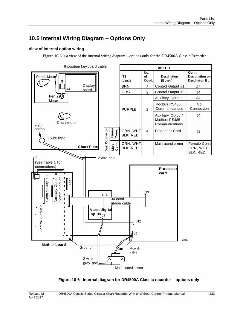
Parts List Internal Wiring Diagram – Options Only
Release M DR4500A Classic Series Circular Chart Recorder With or Without Control Product Manual 233 April 2017
10.5 Internal Wiring Diagram – Options Only
View of internal option wiring
Figure 10-6 is a view of the internal wiring diagram—options only for the DR4500A Classic Recorder.
Chart Plate
Display
board
Pen 2
Motor
Chart motor
9 position key board cable
J3
2 wire light
Pen 1 Motor
Alarm/digital
inputs
Mother board
J8 1J13
J2
Processor
card
J2
J1 1
34 cond.
ribbon cable
Main transf ormer
2 wire
gray pair
J12
Co
ntr
ol O
utp
ut
2
Co
ntr
ol O
utp
ut
1
Au
xili
ary
Ou
tpu
t o
r
Co
mm
un
ica
tio
n
4 cond.
cable
Ground
Te
st
1
T1
(See Table 1 f or
connections)
Conn.
Designation on
Destinaton Bd.
J4
J4
J4
J2GRN. WHT.
BLK. RED
2
2
2
4
No.
of
Cond.
Destination
(Board)
BRN.
ORG.
PURPLE
Female Conn.
GRN, WHT,
BLK, RED.
Processor Card
Control Output #1
Control Output #2
Auxiliary Output
Main transf ormerGRN. WHT.
BLK. RED
T1
Leads
TABLE 1
Du
al C
on
necto
r
Male
Co
nn
.
Fem
ale
Co
nn
.
22819
Light
option
2 wire pair
No
Connection
Modbus RS485
Communications
J4Auxiliary Output/
Modbus RS485
Communications
Figure 10-6 Internal diagram for DR4500A Classic recorder – options only

Parts List Internal Wiring Diagram – Options Only
234 DR4500A Classic Series Circular Chart Recorder With or Without Control Product Manual Release L February 2017

Release M DR4500A Classic Series Circular Chart Recorder With or Without Control Product Manual 235 April 2017
A. Foreign Language Safety Instructions

236 DR4500A Classic Series Circular Chart Recorder With or Without Control Product Manual Release M April 2017
SIKKERHESKRAV DA2I-6057
!
For at undgå elektrisk stød med mulighed for personskade, skal alle
sikkerhedsbestemmelser i denne manual følges nøje.
Dette symbol advarer brugeren om en potentiel berøringsfare, såfremt der kan være
adgang til den livsfarlige netspænding.
Beskyttende jordterminal. Terminalen er forberedt for og skal forbindes til beskyttelses-
jordledning i henhold til stærkstrømsberkendtgørelsen (DK).
Hvis udstyret ikke bruges som specificeret i manualen, kan den beskyttelse udstyret yder blive nedsat eller
forsvinde.
Eerstat kun komponenter som udtrykkeligt er specificeret som udskiftelige i manualen.
Alle ledningsforbindelser skal følge stærkstrømsberkendtgørelsen (DK) og udføres af autoriseret erfarent
personel.
Den beskyttende jordterminal skal forbindes først af alle forbindelser (og fjernes som den sidste).
Det anbefales jvf. stærkstrømsberkendtgørelsen, at der installeres en afbryder til frosyningsspændingen nær
udstyret.
UDSTYRS SPECIFIKATIONER
Strømforsyning 102 til 132 Vac - 204 til 264 Vac
Frekvens 49 til 51 Hz - 59 til 61 Hz
Nominel effekt 9 watts max.
OMGIVELSES SPECIFIKATIONER
Placer ikke udstyret i nærheden af brandbare væsker eller dampe.
Temperatur Rumtemperatur : 15 til 55°C
Fugtighed 10 til 90% RH
Vibration 0 til 70 Hz
acceleration 0.1 g
UDSTYRS INSTALLATION
Skriveren skal monteres i en tavle for at forhindre adgang til bagterminaler.
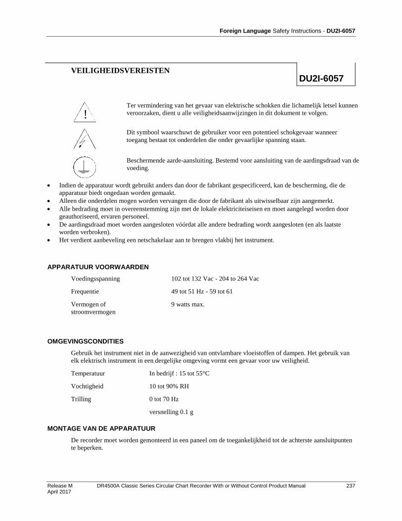
Foreign Language Safety Instructions - DU2I-6057
Release M DR4500A Classic Series Circular Chart Recorder With or Without Control Product Manual 237 April 2017
VEILIGHEIDSVEREISTEN DU2I-6057
!
Ter vermindering van het gevaar van elektrische schokken die lichamelijk letsel kunnen
veroorzaken, dient u alle veiligheidsaanwijzingen in dit dokument te volgen.
Dit symbool waarschuwt de gebruiker voor een potentieel schokgevaar wanneer
toegang bestaat tot onderdelen die onder gevaarlijke spanning staan.
Beschermende aarde-aansluiting. Bestemd voor aansluiting van de aardingsdraad van de
voeding.
Indien de apparatuur wordt gebruikt anders dan door de fabrikant gespecificeerd, kan de bescherming, die de
apparatuur biedt ongedaan worden gemaakt.
Alleen die onderdelen mogen worden vervangen die door de fabrikant als uitwisselbaar zijn aangemerkt.
Alle bedrading moet in overeenstemming zijn met de lokale elektriciteiseisen en moet aangelegd worden door
geauthoriseerd, ervaren personeel.
De aardingsdraad moet worden aangesloten vóórdat alle andere bedrading wordt aangesloten (en als laatste
worden verbroken).
Het verdient aanbeveling een netschakelaar aan te brengen vlakbij het instrument.
APPARATUUR VOORWAARDEN
Voedingsspanning 102 tot 132 Vac - 204 to 264 Vac
Frequentie 49 tot 51 Hz - 59 tot 61
Vermogen of
stroomvermogen
9 watts max.
OMGEVINGSCONDITIES
Gebruik het instrument niet in de aanwezigheid van ontvlambare vloeistoffen of dampen. Het gebruik van
elk elektrisch instrument in een dergelijke omgeving vormt een gevaar voor uw veiligheid.
Temperatuur In bedrijf : 15 tot 55°C
Vochtigheid 10 tot 90% RH
Trilling 0 tot 70 Hz
versnelling 0.1 g
MONTAGE VAN DE APPARATUUR
De recorder moet worden gemonteerd in een paneel om de toegankelijkheid tot de achterste aansluitpunten
te beperken.
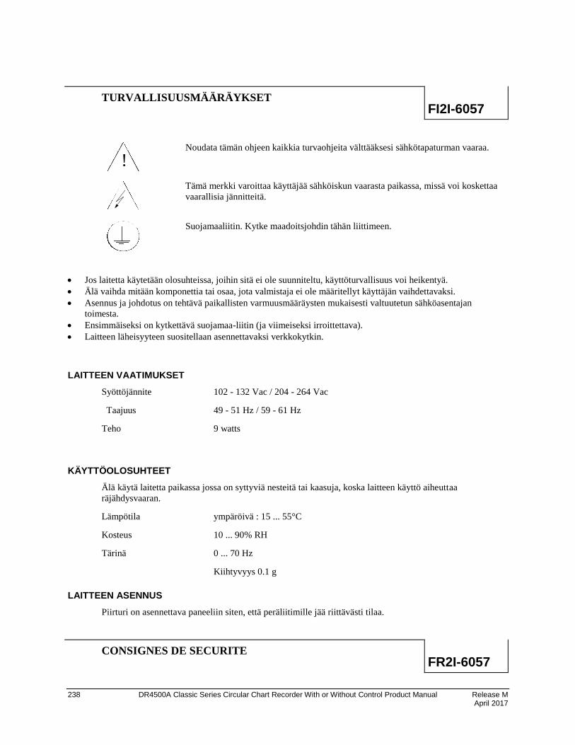
238 DR4500A Classic Series Circular Chart Recorder With or Without Control Product Manual Release M April 2017
TURVALLISUUSMÄÄRÄYKSET FI2I-6057
!
Noudata tämän ohjeen kaikkia turvaohjeita välttääksesi sähkötapaturman vaaraa.
Tämä merkki varoittaa käyttäjää sähköiskun vaarasta paikassa, missä voi koskettaa
vaarallisia jännitteitä.
Suojamaaliitin. Kytke maadoitsjohdin tähän liittimeen.
Jos laitetta käytetään olosuhteissa, joihin sitä ei ole suunniteltu, käyttöturvallisuus voi heikentyä.
Älä vaihda mitään komponettia tai osaa, jota valmistaja ei ole määritellyt käyttäjän vaihdettavaksi.
Asennus ja johdotus on tehtävä paikallisten varmuusmääräysten mukaisesti valtuutetun sähköasentajan
toimesta.
Ensimmäiseksi on kytkettävä suojamaa-liitin (ja viimeiseksi irroittettava).
Laitteen läheisyyteen suositellaan asennettavaksi verkkokytkin.
LAITTEEN VAATIMUKSET
Syöttöjännite 102 - 132 Vac / 204 - 264 Vac
Taajuus 49 - 51 Hz / 59 - 61 Hz
Teho 9 watts
KÄYTTÖOLOSUHTEET
Älä käytä laitetta paikassa jossa on syttyviä nesteitä tai kaasuja, koska laitteen käyttö aiheuttaa
räjähdysvaaran.
Lämpötila ympäröivä : 15 ... 55°C
Kosteus 10 ... 90% RH
Tärinä 0 ... 70 Hz
Kiihtyvyys 0.1 g
LAITTEEN ASENNUS
Piirturi on asennettava paneeliin siten, että peräliitimille jää riittävästi tilaa.
CONSIGNES DE SECURITE FR2I-6057

Foreign Language Safety Instructions - FR2I-6057
Release M DR4500A Classic Series Circular Chart Recorder With or Without Control Product Manual 239 April 2017
!
Pour réduire tout risque de décharge électrique qui pourrait provoquer une lésion
corporelle, respectez toutes les consignes de sécurité de cette documentation.
Ce symbole avertit l'utilisateur d'un risque électrique potentiel lorsqu'il peut avoir accès
à des éléments sous tension.
Borne de mise à la terre. Destinée au raccordement du conducteur de mise à la terre de
l'alimentation.
Si l'équipement est utilisé dans un but non spécifié par le constructeur, la protection fournie avec cet équipement
peut être affectée.
Aucun composant (ou pièce) ne doit être remplacé s'il n'est pas explicitement spécifié comme tel par le
constructeur.
Tous les câblages doivent être conformes aux normes locales et doivent être réalisés par un personnel autorisé et
expérimenté.
La borne de masse doit être raccordée avant tout autre câblage (et débranchée en dernier).
Il est obligatoire de connecter cet appareil sur une ligne possédant un moyen de coupure près de l'appareil.
CARACTERISTIQUES DE L'EQUIPEMENT
Tension
d'alimentation
102 à 132 Vac ou 204 à 264 Vca
Fréquence 49 à 51 – 59 à 61 Hz
Puissance ou
courant
9 watts max.
CONDITIONS AMBIANTES
Ne jamais utiliser cet équipement en présence de liquides ou vapeurs inflammables.
L'utilisation de tout instrument électrique dans un tel environnement pourrait présenter un risque pour la
sécurité.
Température Ambiante : 15 à 55°C
Humidité 10 à 90 % HR
Vibration Fréquence : 0 à 70 Hz
Accélération 0.1 g
INSTALLATION DE L'EQUIPEMENT
Cet appareil doit être monté dans un panneau pour limiter l'accès aux bornes arrières par l'opérateur.
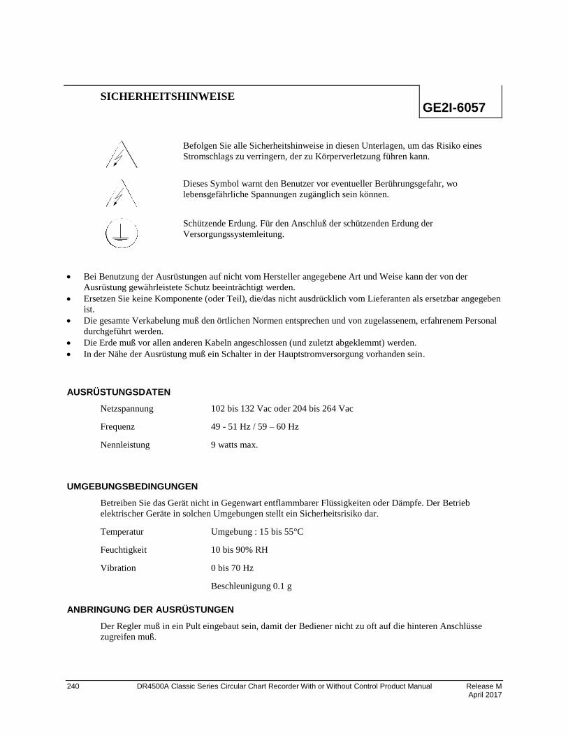
240 DR4500A Classic Series Circular Chart Recorder With or Without Control Product Manual Release M April 2017
SICHERHEITSHINWEISE GE2I-6057
Befolgen Sie alle Sicherheitshinweise in diesen Unterlagen, um das Risiko eines
Stromschlags zu verringern, der zu Körperverletzung führen kann.
Dieses Symbol warnt den Benutzer vor eventueller Berührungsgefahr, wo
lebensgefährliche Spannungen zugänglich sein können.
Schützende Erdung. Für den Anschluß der schützenden Erdung der
Versorgungssystemleitung.
Bei Benutzung der Ausrüstungen auf nicht vom Hersteller angegebene Art und Weise kann der von der
Ausrüstung gewährleistete Schutz beeinträchtigt werden.
Ersetzen Sie keine Komponente (oder Teil), die/das nicht ausdrücklich vom Lieferanten als ersetzbar angegeben
ist.
Die gesamte Verkabelung muß den örtlichen Normen entsprechen und von zugelassenem, erfahrenem Personal
durchgeführt werden.
Die Erde muß vor allen anderen Kabeln angeschlossen (und zuletzt abgeklemmt) werden.
In der Nähe der Ausrüstung muß ein Schalter in der Hauptstromversorgung vorhanden sein.
AUSRÜSTUNGSDATEN
Netzspannung 102 bis 132 Vac oder 204 bis 264 Vac
Frequenz 49 - 51 Hz / 59 – 60 Hz
Nennleistung 9 watts max.
UMGEBUNGSBEDINGUNGEN
Betreiben Sie das Gerät nicht in Gegenwart entflammbarer Flüssigkeiten oder Dämpfe. Der Betrieb
elektrischer Geräte in solchen Umgebungen stellt ein Sicherheitsrisiko dar.
Temperatur Umgebung : 15 bis 55°C
Feuchtigkeit 10 bis 90% RH
Vibration 0 bis 70 Hz
Beschleunigung 0.1 g
ANBRINGUNG DER AUSRÜSTUNGEN
Der Regler muß in ein Pult eingebaut sein, damit der Bediener nicht zu oft auf die hinteren Anschlüsse
zugreifen muß.

Foreign Language Safety Instructions - GR2I-6057
Release M DR4500A Classic Series Circular Chart Recorder With or Without Control Product Manual 241 April 2017
GR2I-6057
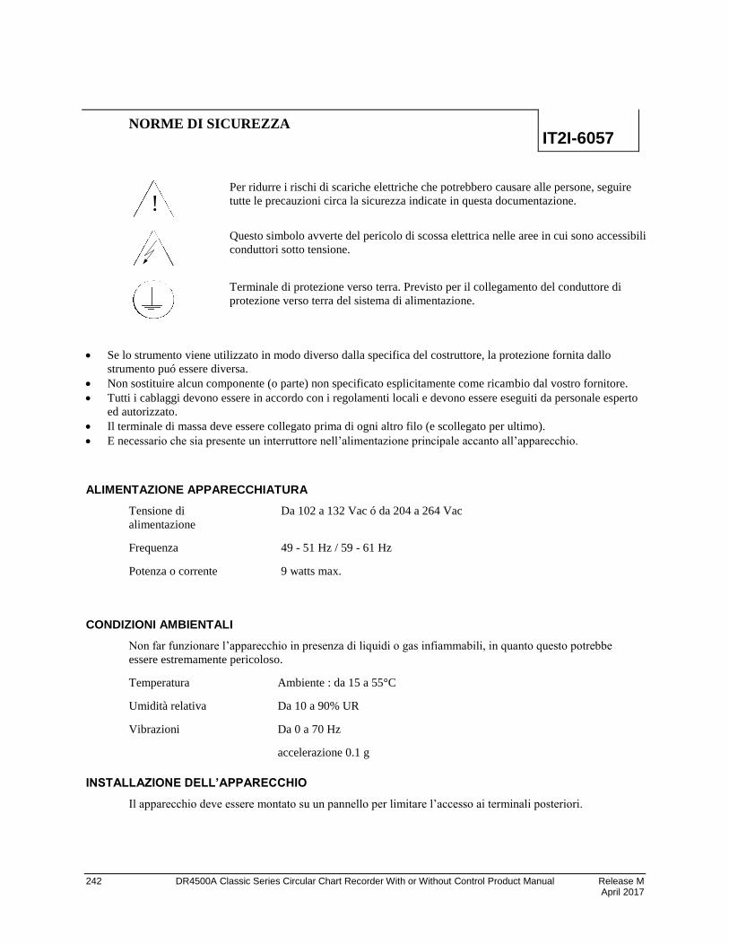
242 DR4500A Classic Series Circular Chart Recorder With or Without Control Product Manual Release M April 2017
NORME DI SICUREZZA IT2I-6057
!
Per ridurre i rischi di scariche elettriche che potrebbero causare alle persone, seguire
tutte le precauzioni circa la sicurezza indicate in questa documentazione.
Questo simbolo avverte del pericolo di scossa elettrica nelle aree in cui sono accessibili
conduttori sotto tensione.
Terminale di protezione verso terra. Previsto per il collegamento del conduttore di
protezione verso terra del sistema di alimentazione.
Se lo strumento viene utilizzato in modo diverso dalla specifica del costruttore, la protezione fornita dallo
strumento puó essere diversa.
Non sostituire alcun componente (o parte) non specificato esplicitamente come ricambio dal vostro fornitore.
Tutti i cablaggi devono essere in accordo con i regolamenti locali e devono essere eseguiti da personale esperto
ed autorizzato.
Il terminale di massa deve essere collegato prima di ogni altro filo (e scollegato per ultimo).
E necessario che sia presente un interruttore nell’alimentazione principale accanto all’apparecchio.
ALIMENTAZIONE APPARECCHIATURA
Tensione di
alimentazione
Da 102 a 132 Vac ó da 204 a 264 Vac
Frequenza 49 - 51 Hz / 59 - 61 Hz
Potenza o corrente 9 watts max.
CONDIZIONI AMBIENTALI
Non far funzionare l’apparecchio in presenza di liquidi o gas infiammabili, in quanto questo potrebbe
essere estremamente pericoloso.
Temperatura Ambiente : da 15 a 55°C
Umidità relativa Da 10 a 90% UR
Vibrazioni Da 0 a 70 Hz
accelerazione 0.1 g
INSTALLAZIONE DELL’APPARECCHIO
Il apparecchio deve essere montato su un pannello per limitare l’accesso ai terminali posteriori.
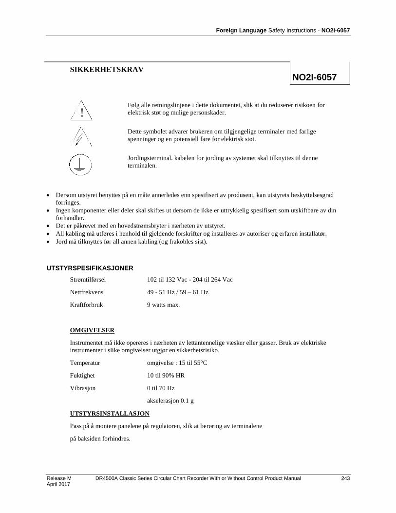
Foreign Language Safety Instructions - NO2I-6057
Release M DR4500A Classic Series Circular Chart Recorder With or Without Control Product Manual 243 April 2017
SIKKERHETSKRAV NO2I-6057
!
Følg alle retningslinjene i dette dokumentet, slik at du reduserer risikoen for
elektrisk støt og mulige personskader.
Dette symbolet advarer brukeren om tilgjengelige terminaler med farlige
spenninger og en potensiell fare for elektrisk støt.
Jordingsterminal. kabelen for jording av systemet skal tilknyttes til denne
terminalen.
Dersom utstyret benyttes på en måte annerledes enn spesifisert av produsent, kan utstyrets beskyttelsesgrad
forringes.
Ingen komponenter eller deler skal skiftes ut dersom de ikke er uttrykkelig spesifisert som utskiftbare av din
forhandler.
Det er påkrevet med en hovedstrømsbryter i nærheten av utstyret.
All kabling må utføres i henhold til gjeldende forskrifter og installeres av autoriser og erfaren installatør.
Jord må tilknyttes før all annen kabling (og frakobles sist).
UTSTYRSPESIFIKASJONER
Strømtilførsel 102 til 132 Vac - 204 til 264 Vac
Nettfrekvens 49 - 51 Hz / 59 – 61 Hz
Kraftforbruk 9 watts max.
OMGIVELSER
Instrumentet må ikke opereres i nærheten av lettantennelige væsker eller gasser. Bruk av elektriske
instrumenter i slike omgivelser utgjør en sikkerhetsrisiko.
Temperatur omgivelse : 15 til 55°C
Fuktighet 10 til 90% HR
Vibrasjon 0 til 70 Hz
akselerasjon 0.1 g
UTSTYRSINSTALLASJON
Pass på å montere panelene på regulatoren, slik at berøring av terminalene
på baksiden forhindres.
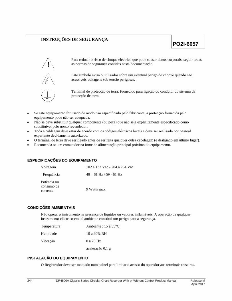
244 DR4500A Classic Series Circular Chart Recorder With or Without Control Product Manual Release M April 2017
INSTRUÇÕES DE SEGURANÇA PO2I-6057
!
Para reduzir o risco de choque eléctrico que pode causar danos corporais, seguir todas
as normas de segurança contidas nesta documentação.
Este símbolo avisa o utilizador sobre um eventual perigo de choque quando são
acessíveis voltagens sob tensão perigosas.
Terminal de protecção de terra. Fornecido para ligação do condutor do sistema da
protecção de terra.
Se este equipamento for usado de modo não especificado pelo fabricante, a protecção fornecida pelo
equipamento pode não ser adequada.
Não se deve substituir qualquer componente (ou peça) que não seja explicitamente especificado como
substituível pelo nosso revendedor.
Toda a cablagem deve estar de acordo com os códigos eléctricos locais e deve ser realizada por pessoal
experiente devidamente autorizado.
O terminal de terra deve ser ligado antes de ser feita qualquer outra cabelagem (e desligado em último lugar).
Recomenda-se um comutador na fonte de alimentação principal próximo do equipamento.
ESPECIFICAÇÕES DO EQUIPAMENTO
Voltagem 102 a 132 Vac - 204 a 264 Vac
Frequência 49 – 61 Hz / 59 - 61 Hz
Potência ou
consumo de
corrente
9 Watts max.
CONDIÇÕES AMBIENTAIS
Não operar o instrumento na presença de líquidos ou vapores inflamáveis. A operação de qualquer
instrumento eléctrico em tal ambiente constitui um perigo para a segurança.
Temperatura Ambiente : 15 a 55°C
Humidade 10 a 90% RH
Vibração 0 a 70 Hz
aceleração 0.1 g
INSTALAÇÃO DO EQUIPAMENTO
O Registrador deve ser montado num painel para limitar o acesso do operador aos terminais traseiros.
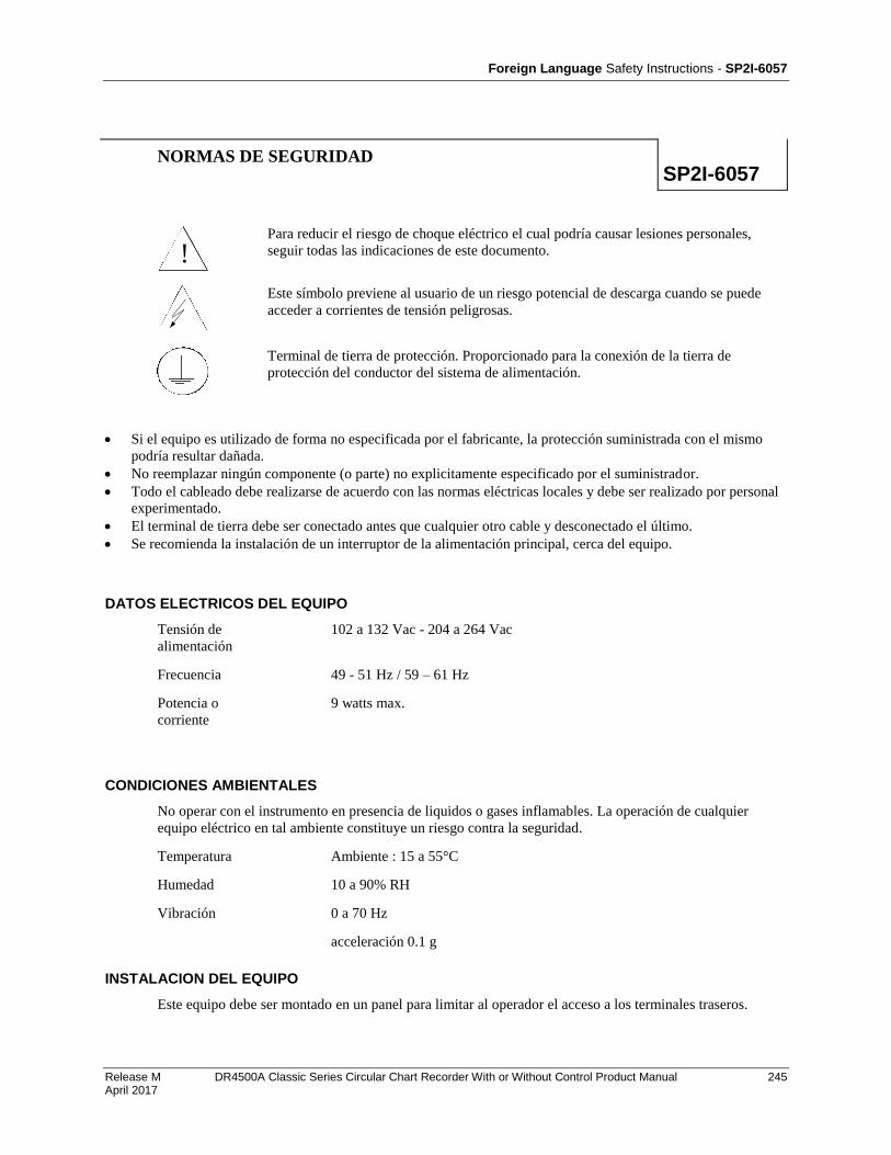
Foreign Language Safety Instructions - SP2I-6057
Release M DR4500A Classic Series Circular Chart Recorder With or Without Control Product Manual 245 April 2017
NORMAS DE SEGURIDAD SP2I-6057
!
Para reducir el riesgo de choque eléctrico el cual podría causar lesiones personales,
seguir todas las indicaciones de este documento.
Este símbolo previene al usuario de un riesgo potencial de descarga cuando se puede
acceder a corrientes de tensión peligrosas.
Terminal de tierra de protección. Proporcionado para la conexión de la tierra de
protección del conductor del sistema de alimentación.
Si el equipo es utilizado de forma no especificada por el fabricante, la protección suministrada con el mismo
podría resultar dañada.
No reemplazar ningún componente (o parte) no explicitamente especificado por el suministrador.
Todo el cableado debe realizarse de acuerdo con las normas eléctricas locales y debe ser realizado por personal
experimentado.
El terminal de tierra debe ser conectado antes que cualquier otro cable y desconectado el último.
Se recomienda la instalación de un interruptor de la alimentación principal, cerca del equipo.
DATOS ELECTRICOS DEL EQUIPO
Tensión de
alimentación
102 a 132 Vac - 204 a 264 Vac
Frecuencia 49 - 51 Hz / 59 – 61 Hz
Potencia o
corriente
9 watts max.
CONDICIONES AMBIENTALES
No operar con el instrumento en presencia de liquidos o gases inflamables. La operación de cualquier
equipo eléctrico en tal ambiente constituye un riesgo contra la seguridad.
Temperatura Ambiente : 15 a 55°C
Humedad 10 a 90% RH
Vibración 0 a 70 Hz
acceleración 0.1 g
INSTALACION DEL EQUIPO
Este equipo debe ser montado en un panel para limitar al operador el acceso a los terminales traseros.
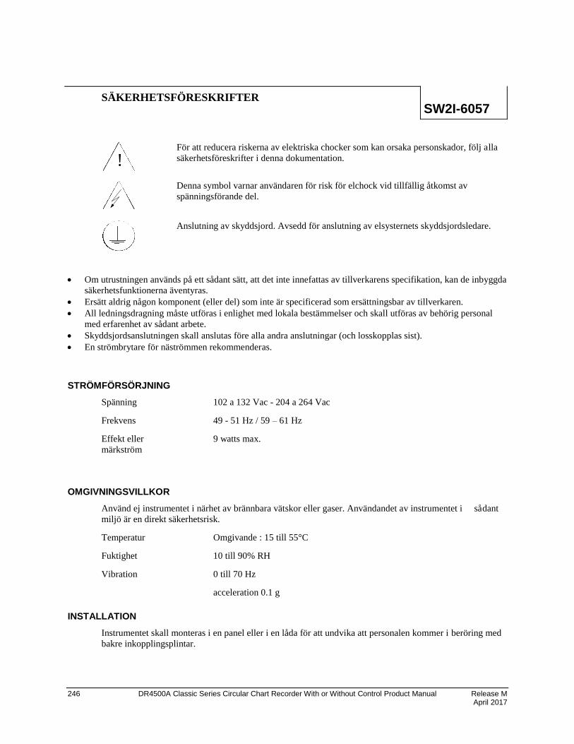
246 DR4500A Classic Series Circular Chart Recorder With or Without Control Product Manual Release M April 2017
SÄKERHETSFÖRESKRIFTER SW2I-6057
!
För att reducera riskerna av elektriska chocker som kan orsaka personskador, följ alla
säkerhetsföreskrifter i denna dokumentation.
Denna symbol varnar användaren för risk för elchock vid tillfällig åtkomst av
spänningsförande del.
Anslutning av skyddsjord. Avsedd för anslutning av elsysternets skyddsjordsledare.
Om utrustningen används på ett sådant sätt, att det inte innefattas av tillverkarens specifikation, kan de inbyggda
säkerhetsfunktionerna äventyras.
Ersätt aldrig någon komponent (eller del) som inte är specificerad som ersättningsbar av tillverkaren.
All ledningsdragning måste utföras i enlighet med lokala bestämmelser och skall utföras av behörig personal
med erfarenhet av sådant arbete.
Skyddsjordsanslutningen skall anslutas före alla andra anslutningar (och losskopplas sist).
En strömbrytare för näströmmen rekommenderas.
STRÖMFÖRSÖRJNING
Spänning 102 a 132 Vac - 204 a 264 Vac
Frekvens 49 - 51 Hz / 59 – 61 Hz
Effekt eller
märkström
9 watts max.
OMGIVNINGSVILLKOR
Använd ej instrumentet i närhet av brännbara vätskor eller gaser. Användandet av instrumentet i sådant
miljö är en direkt säkerhetsrisk.
Temperatur Omgivande : 15 till 55°C
Fuktighet 10 till 90% RH
Vibration 0 till 70 Hz
acceleration 0.1 g
INSTALLATION
Instrumentet skall monteras i en panel eller i en låda för att undvika att personalen kommer i beröring med
bakre inkopplingsplintar.
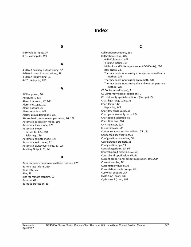
Release M DR4500A Classic Series Circular Chart Recorder With or Without Control Product Manual 247 April 2017
Index
0
0-10 Volt dc inputs, 37 0–10 Volt inputs, 189
4
4-20 mA auxiliary output wiring, 52 4-20 mA control output wiring, 39 4-20 mA input wiring, 35 4–20 mA inputs, 190
A
AC line power, 30 Accutune II, 139 Alarm hysteresis, 73, 108 Alarm messages, 127 Alarm outputs, 45 Alarm setpoints, 142 Alarms group definitions, 107 Atmospheric pressure compensation, 76, 112 Automatic calibration mode, 198 Automatic local mode, 129 Automatic mode
Return to, 130, 160 Selecting, 129
Automatic remote mode, 129 Automatic switchover, 91 Automatic switchover value, 67, 92 Auxiliary Output, 73, 74
B
Basic recorder components without options, 226 Battery test failure, 210 Baud rate, 75 Bias, 93 Bias for remote setpoint, 67 Burnout, 63 Burnout protection, 85
C
Calibration procedure, 191 Calibration set up, 183
0-10 Volt inputs, 189 4-20 mA inputs, 190 Millivolts and Volts inputs (except 0-10 Volts), 188 RTD inputs, 187 Thermocouple inputs using a compensated calibrator
method, 185 Thermocouple inputs using an ice bath, 184 Thermocouple inputs using the ambient temperature
method, 186 CE Conformity (Europe), 1 CE Conformity special conditions, 7 CE conformity special conditions (Europe), 27 Chart high range value, 86 Chart lamp, 147
Replacing, 147 Chart low range value, 86 Chart plate assembly parts, 224 Chart speed selection, 65 Chart time line, 118 CHN indicator, 128 Circuit-breaker, 30 Communications station address, 75, 111 Condensed specifications, 8 Configuration procedure, 60 Configuration prompts, 56 Configuration tips, 59 Control algorithm, 68, 96 Control output direction, 67, 94 Controller dropoff value, 67, 94 Current proportional output calibration, 195, 200 Current simplex, 98 Current/relay duplex, 98 Current/time duplex range, 68 Customer support, 204 Cycle time (heat), 102 Cycle time 2 (cool), 102
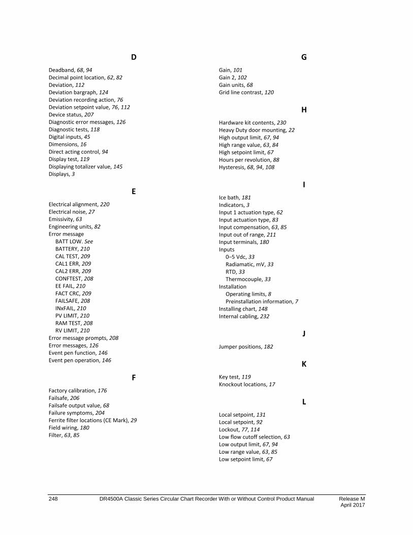
248 DR4500A Classic Series Circular Chart Recorder With or Without Control Product Manual Release M April 2017
D
Deadband, 68, 94 Decimal point location, 62, 82 Deviation, 112 Deviation bargraph, 124 Deviation recording action, 76 Deviation setpoint value, 76, 112 Device status, 207 Diagnostic error messages, 126 Diagnostic tests, 118 Digital inputs, 45 Dimensions, 16 Direct acting control, 94 Display test, 119 Displaying totalizer value, 145 Displays, 3
E
Electrical alignment, 220 Electrical noise, 27 Emissivity, 63 Engineering units, 82 Error message
BATT LOW. See BATTERY, 210 CAL TEST, 209 CAL1 ERR, 209 CAL2 ERR, 209 CONFTEST, 208 EE FAIL, 210 FACT CRC, 209 FAILSAFE, 208 INxFAIL, 210 PV LIMIT, 210 RAM TEST, 208 RV LIMIT, 210
Error message prompts, 208 Error messages, 126 Event pen function, 146 Event pen operation, 146
F
Factory calibration, 176 Failsafe, 206 Failsafe output value, 68 Failure symptoms, 204 Ferrite filter locations (CE Mark), 29 Field wiring, 180 Filter, 63, 85
G
Gain, 101 Gain 2, 102 Gain units, 68 Grid line contrast, 120
H
Hardware kit contents, 230 Heavy Duty door mounting, 22 High output limit, 67, 94 High range value, 63, 84 High setpoint limit, 67 Hours per revolution, 88 Hysteresis, 68, 94, 108
I
Ice bath, 181 Indicators, 3 Input 1 actuation type, 62 Input actuation type, 83 Input compensation, 63, 85 Input out of range, 211 Input terminals, 180 Inputs
0–5 Vdc, 33 Radiamatic, mV, 33 RTD, 33 Thermocouple, 33
Installation Operating limits, 8 Preinstallation information, 7
Installing chart, 148 Internal cabling, 232
J
Jumper positions, 182
K
Key test, 119 Knockout locations, 17
L
Local setpoint, 131 Local setpoint, 92 Lockout, 77, 114 Low flow cutoff selection, 63 Low output limit, 67, 94 Low range value, 63, 85 Low setpoint limit, 67
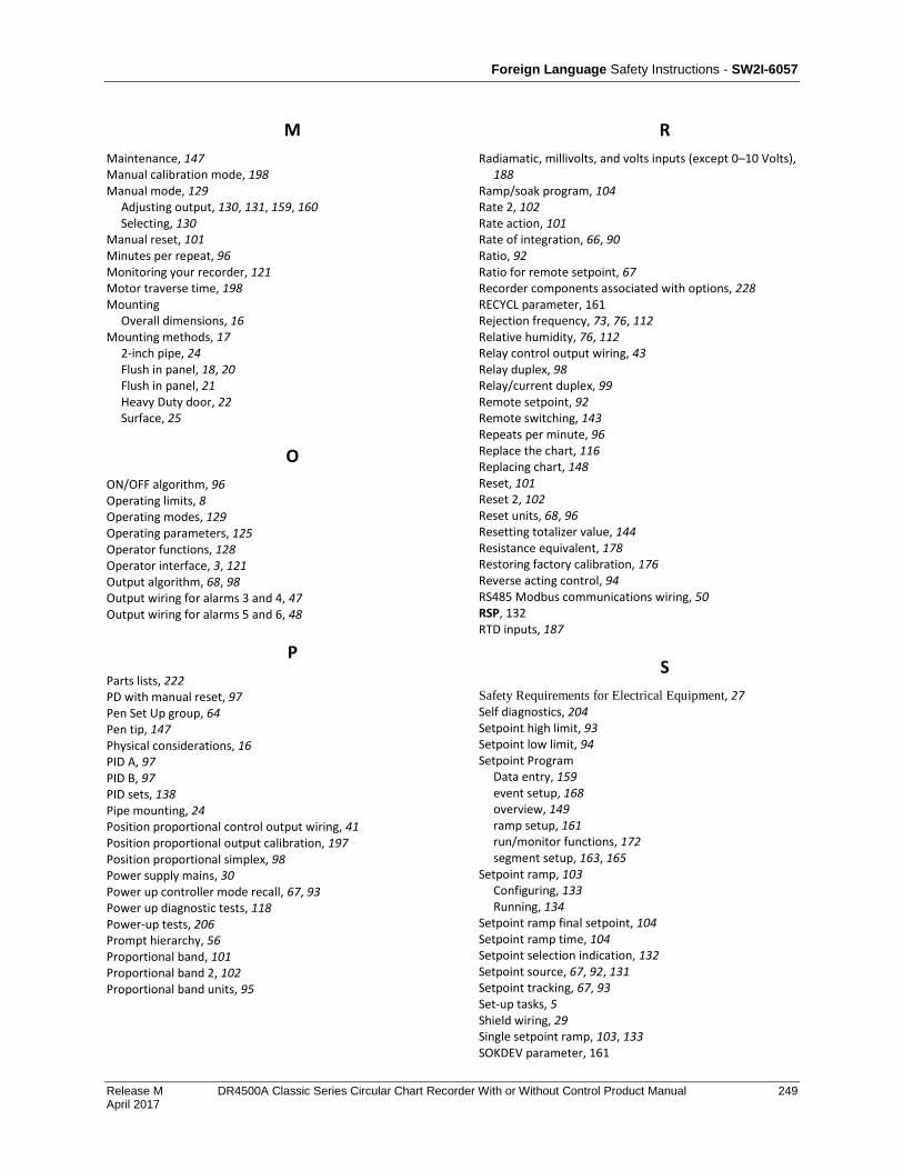
Foreign Language Safety Instructions - SW2I-6057
Release M DR4500A Classic Series Circular Chart Recorder With or Without Control Product Manual 249 April 2017
M
Maintenance, 147 Manual calibration mode, 198 Manual mode, 129
Adjusting output, 130, 131, 159, 160 Selecting, 130
Manual reset, 101 Minutes per repeat, 96 Monitoring your recorder, 121 Motor traverse time, 198 Mounting
Overall dimensions, 16 Mounting methods, 17
2-inch pipe, 24 Flush in panel, 18, 20 Flush in panel, 21 Heavy Duty door, 22 Surface, 25
O
ON/OFF algorithm, 96 Operating limits, 8 Operating modes, 129 Operating parameters, 125 Operator functions, 128 Operator interface, 3, 121 Output algorithm, 68, 98 Output wiring for alarms 3 and 4, 47 Output wiring for alarms 5 and 6, 48
P
Parts lists, 222 PD with manual reset, 97 Pen Set Up group, 64 Pen tip, 147 Physical considerations, 16 PID A, 97 PID B, 97 PID sets, 138 Pipe mounting, 24 Position proportional control output wiring, 41 Position proportional output calibration, 197 Position proportional simplex, 98 Power supply mains, 30 Power up controller mode recall, 67, 93 Power up diagnostic tests, 118 Power-up tests, 206 Prompt hierarchy, 56 Proportional band, 101 Proportional band 2, 102 Proportional band units, 95
R
Radiamatic, millivolts, and volts inputs (except 0–10 Volts), 188
Ramp/soak program, 104 Rate 2, 102 Rate action, 101 Rate of integration, 66, 90 Ratio, 92 Ratio for remote setpoint, 67 Recorder components associated with options, 228 RECYCL parameter, 161 Rejection frequency, 73, 76, 112 Relative humidity, 76, 112 Relay control output wiring, 43 Relay duplex, 98 Relay/current duplex, 99 Remote setpoint, 92 Remote switching, 143 Repeats per minute, 96 Replace the chart, 116 Replacing chart, 148 Reset, 101 Reset 2, 102 Reset units, 68, 96 Resetting totalizer value, 144 Resistance equivalent, 178 Restoring factory calibration, 176 Reverse acting control, 94 RS485 Modbus communications wiring, 50 RSP, 132 RTD inputs, 187
S
Safety Requirements for Electrical Equipment, 27 Self diagnostics, 204 Setpoint high limit, 93 Setpoint low limit, 94 Setpoint Program
Data entry, 159 event setup, 168 overview, 149 ramp setup, 161 run/monitor functions, 172 segment setup, 163, 165
Setpoint ramp, 103 Configuring, 133 Running, 134
Setpoint ramp final setpoint, 104 Setpoint ramp time, 104 Setpoint selection indication, 132 Setpoint source, 67, 92, 131 Setpoint tracking, 67, 93 Set-up tasks, 5 Shield wiring, 29 Single setpoint ramp, 103, 133 SOKDEV parameter, 161

250 DR4500A Classic Series Circular Chart Recorder With or Without Control Product Manual Release M April 2017
SPPROG parameter, 161 Start up, 120 Stylus, 120 Support and Contact Information, iv Suppression filters, 29 Switchover value, 136
T
Telephone and Email Contacts, iv Temperature units, 62, 82 Thermocouple inputs using a compensated calibrator
method, 185 Thermocouple inputs using an ice bath, 184 Thermocouple inputs using the ambient temperature
method, 186 Totalizer, 66 Totalizer group definitions, 89 Totalizer reset, 66, 67 Totalizer scale factor, 66 Totalizer value, 144
Displaying, 145 Resetting, 144
Trace line contrast, 120 Transmitter characterization, 63, 84 Troubleshooting procedures, 213 Ttransmitter power, 35 Tuning constants, 136 Tuning group prompt definitions, 100 Tuning messages, 127 Tuning parameter sets, 67, 91 Two local setpoints, 92 Two sets of tuning constants, 136
V
Visual failure symptoms, 204, 212 Voltage equivalent, 178
W
Wire bundling, 28 Wiring
0-10 Vdc inputs, 37 0-5 Vdc inputs, 33 4-20 mA auxiliary output, 52 4-20 mA control output, 39 4-20 mA inputs. See AC line power. See Electrical noise precautions, 27 mV inputs, 33 Position proportional control output, 41 Radiamatic inputs, 33 Relay control output, 43 RS485 Modbus communications, 50 RTD inputs, 33 Shields, 29 Thermocouple inputs, 33 Transmitter power. See Wire bundling, 28 Wiring the recorder, 29
Wiring for PV inputs, 183 0-10 Volt inputs, 189 4-20 mA inputs, 190 Millivolts and Volts inputs (except 0-10 Volts), 188 RTD inputs, 187 Thermocouple inputs using a compensated calibrator
method, 185 Thermocouple inputs using an ice bath, 184 Thermocouple inputs using the ambient temperature
method, 186 Error! Cannot open file referenced on page 13
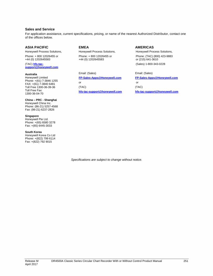
Release M DR4500A Classic Series Circular Chart Recorder With or Without Control Product Manual 251 April 2017
Sales and Service
For application assistance, current specifications, pricing, or name of the nearest Authorized Distributor, contact one of the offices below.
ASIA PACIFIC Honeywell Process Solutions,
Phone: + 800 12026455 or +44 (0) 1202645583
(TAC) [email protected]
Australia Honeywell Limited Phone: +(61) 7-3846 1255 FAX: +(61) 7-3840 6481 Toll Free 1300-36-39-36 Toll Free Fax: 1300-36-04-70 China – PRC - Shanghai Honeywell China Inc. Phone: (86-21) 5257-4568 Fax: (86-21) 6237-2826
Singapore Honeywell Pte Ltd. Phone: +(65) 6580 3278 Fax: +(65) 6445-3033 South Korea Honeywell Korea Co Ltd Phone: +(822) 799 6114 Fax: +(822) 792 9015
EMEA Honeywell Process Solutions,
Phone: + 800 12026455 or +44 (0) 1202645583
Email: (Sales)
or
(TAC)
AMERICAS Honeywell Process Solutions,
Phone: (TAC) (800) 423-9883 or (215) 641-3610
(Sales) 1-800-343-0228
Email: (Sales)
or
(TAC)
Specifications are subject to change without notice.

For more information
To learn more about SmartLine Transmitters, visit www.honeywellprocess.com
Or contact your Honeywell Account Manager
Process Solutions
Honeywell
1250 W Sam Houston Pkwy S Houston, USA, TX 77042
Honeywell Control Systems Ltd Honeywell House, Skimped Hill Lane Bracknell, England, RG12 1EB
44-45-25-35 Rev.M April 2017
2017 Honeywell International Inc.
Shanghai City Centre, 100 Jungi Road Shanghai, China 20061 www.honeywellprocess.com