user guide circular chart recorder - library.e.abb.com · circular chart recorder flow supplement...
TRANSCRIPT

Circular Chart Recorder
Flow Supplement for C1492
User GuideIM/1492–FW_8

ABB
The Company
We are an established world force in the design and manufacture of instrumentation forindustrial process control, flow measurement, gas and liquid analysis and environmentalapplications.
As a part of ABB, a world leader in process automation technology, we offer customersapplication expertise, service and support worldwide.
We are committed to teamwork, high quality manufacturing, advanced technology andunrivalled service and support.
The quality, accuracy and performance of the Company’s products result from over 100 yearsexperience, combined with a continuous program of innovative design and development toincorporate the latest technology.
The UKAS Calibration Laboratory No. 0255 is just one of the ten flow calibration plantsoperated by the Company and is indicative of our dedication to quality and accuracy.
Health and SafetyTo ensure that our products are safe and without risk to health, the following points must be noted:
1. The relevant sections of these instructions must be read carefully before proceeding.
2. Warning labels on containers and packages must be observed.
3. Installation, operation, maintenance and servicing must only be carried out by suitably trained personnel and in accordance with theinformation given.
4. Normal safety precautions must be taken to avoid the possibility of an accident occurring when operating in conditions of high pressureand/or temperature.
5. Chemicals must be stored away from heat, protected from temperature extremes and powders kept dry. Normal safe handling proceduresmust be used.
6. When disposing of chemicals ensure that no two chemicals are mixed.
Safety advice concerning the use of the equipment described in this manual or any relevant hazard data sheets (where applicable) may beobtained from the Company address on the back cover, together with servicing and spares information.
EN ISO 9001:2000
Cert. No. Q 05907
REGISTERE
D
EN 29001 (ISO 9001)
Lenno, Italy – Cert. No. 9/90A
0255
Stonehouse, U.K.
Warning – Refer to the manual for instructions
Caution – Risk of electric shock
Protective earth (ground) terminal
Earth (ground) terminal
Direct current supply only
Alternating current supply only
Both direct and alternating current supply
The equipment is protectedthrough double insulation
Electrical Safety
This instrument complies with the requirements of CEI/IEC 61010-1:1993 "Safety requirements for electrical equipment formeasurement, control, and laboratory use". If the instrument is used in a manner NOT specified by the Company, the protectionprovided by the instrument may be impaired.
Symbols
One or more of the following symbols may appear on the instrument labelling:
Information in this manual is intended only to assist our customers in the efficient operation of our equipment. Use of this manualfor any other purpose is specifically prohibited and its contents are not to be reproduced in full or part without prior approval of theTechnical Publications Department.

1
1(F) INTRODUCTIONThis supplement provides instructions on the features of 1492Flow Recorders which differ from those of the basic 1492Recorders described in instruction booklet IM/1492.
The Flow Recorders provide indication and recording of flowrates from input signals with linear, square law or power lawcharacteristics or of the pulse frequency type.
Totalisation is available for each channel and may be switchedon or off as required.
The flow total for any channel may be viewed on the digitaldisplay and reset via the front panel controls. An additionalinternal ‘Secure’ total is also provided which can only be resetafter gaining access to the Programming Pages.
External counters with their own power supplies can be drivenusing any of the standard relay module options. Alternatively, acounter drive module is available for which no external powersupply is needed.
This manual must be read in conjunction with the 1492 StandardOptions Operating Instructions – IM/1492.
1(F) INTRODUCTION ...................................................... 1
2(F) PREPARATION ......................................................... 2
3(F) INSTALLATION ......................................................... 2
4(F) ELECTRICAL CONNECTIONS ................................ 24.1(F) Counter Drive Module ................................. 24.2(F) Frequency Input Module ............................. 4
5(F) FAMILIARISATION WITH CONTROLS,DISPLAY AND L.E.D. INDICATION ......................... 4
6(F) SETTING UP ............................................................ 4
7(F) OPERATION ............................................................. 57.1(F) Operating Page 1 ....................................... 57.2(F) Operating Page 2 ....................................... 6
8(F) PROGRAMMING ...................................................... 78.1(F) Set Up Input Page ...................................... 88.2(F) Set Up Display Page ................................ 108.3(F) Totaliser Set Up Page ................................. 128.4 (F) Set Up Module Page ................................. 14
8.4.1(F) Module Positions 1,2,3. ...................... 148.4.2(F) Module Positions 4,5,6 ....................... 15
9(F) SIMPLE FAULT FINDING ......................................... 18
10(F) CALIBRATION ........................................................ 18
APPENDIX .......................................................................... 19A1(F) Calculation of Pulse Rate andTotal Count ............................................................... 19
CONTENTS Page
2
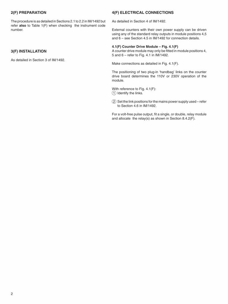
4(F) ELECTRICAL CONNECTIONS
As detailed in Section 4 of IM/1492.
External counters with their own power supply can be drivenusing any of the standard relay outputs in module positions 4,5and 6 – see Section 4.5 in IM/1492 for connection details.
4.1(F) Counter Drive Module – Fig. 4.1(F)A counter drive module may only be fitted in module positions 4,5 and 6 – refer to Fig. 4.1 in IM/1492.
Make connections as detailed in Fig. 4.1(F).
The positioning of two plug-in ‘handbag’ links on the counterdrive board determines the 110V or 230V operation of themodule.
With reference to Fig. 4.1(F):1 Identify the links.
2 Set the link positions for the mains power supply used – referto Section 4.6 in IM/1492.
For a volt-free pulse output, fit a single, or double, relay moduleand allocate the relay(s) as shown in Section 8.4.2(F).
2(F) PREPARATION
The procedure is as detailed in Sections 2.1 to 2.2 in IM/1492 butrefer also to Table 1(F) when checking the instrument codenumber.
3(F) INSTALLATION
As detailed in Section 3 of IM/1492.

3
Fig. 4.1F Counter Drive Module
Fig.4.1(F) Counter Drive Module Connections
PROCESSORP.C.B.
MAINSPOWER SUPPLY
P.C.B.
COUNTERDRIVE P.C.B.
110V
1
2
3 2 1 3 2 1 3 2 1+ -
MAINS INPUT
N L L NL N 0 25V
MAINS OUTPUTINPUT 2INPUT 3 INPUT 1++ --
230V
To Counter

4
4.2(F) Frequency Input ModuleA frequency input module may only be fitted in module positions1,2 or 3 for channels 1,2,3 respectively – refer to Fig. 4.1 in IM/1492.
Make connections and links as detailed in Fig. 4.2(F) and Table2(F). The module is for frequency inputs only and Input TypeFREQ should be selected – see Section 8.4.
Ensure that plug-in links PL1 to PL9 are configured to suit thefrequency input – see Table 2(F).
Fig. 4.2(F) Frequency Input Module Connections
Table 2(F) Frequency Input Board Plug-in Link Selection
5(F) FAMILIARISATION WITH CONTROLS, DISPLAYAND L.E.D. INDICATION
As detailed in Section 5 of IM/1492.
6(F) SETTING UP
As detailed in Section 6 of IM/1492
TBM
PL1
PL2
PL3
PL4
PL5
PL6
PL7
PL8
+ – 0V
PL9
TTL square wave andVoltage inputLo –50V to +1VHi +2V to +50V
PL1 PL2 PL3 PL4 PL5 PL6 PL7 PL8+ – 0V
+ 0V
+ 0V
Valid range
Open collector (2mA)and Dry contact (2mA)
Vortex, VKA/B4mA & 16mA systems
Turbine, Rotary ShuntMeter
Genera l pu rposeA.C. coupled.D.C. offset max. ±50V
General purposeD.C. coupled
+ – *
+ – *
+ – *
+ – *
TBM
0.003 to 0.1Hzto 4kHz
0.003 to 0.1Hzto 4kHz
0.003 to 4kHz
3Hz to 3kHz
3Hz to 4kHz
0.003Hz to4kHz
**
*** Shield connection if required.
** Move PL7 to if frequency compensation required at 1mV/Hz. At high frequency the internal frequencycompensation limits the amplitude of the input signal avoiding saturation of the internal frequency measurementcircuitry and should be used if the applied input waveform increases in amplitude with increasing frequency.
Input Type 3 42 1
3 42 1
3 42 1
3 42 1
3 42 1
3 42 1
3 42 1
3 42 1
Connections 3 42 1
PL9

5
7(F) OPERATION
7.1(F) Operating Page 1As detailed in Section 7 of IM/1492 but with the following additional flow total information.
Note 1. ‘FLOW TOTAL’, its measured value and ‘RESET TOTAL’ are not displayed when ‘TOTALISER’ is turned off in theTotaliser Set Up Page – see page 12.
Note 2. ‘RESET TOTAL’ is not displayed during automatic sequencing, and only during manual sequencing when the resetfunction is enabled in the Totaliser Set Up Page. The total is reset to the Preset Value by selecting ‘Yes’ and pressingthe ‘Enter’ switch –see Section 8.3(F).
Fig. 7.2(F) Operating Page 1, Two-pen Flow Instruments
Fig. 7.1(F) Operating Page 1, Single pen Flow Instruments
ALARM VALUES
SETPOINT VALUES
Standard alarm configuration– see Fig. 8.1 on page 7.
Programmable alarm configuration– see Fig. 8.1 on page 7.
or
Automatic Sequencing
1 # (FlowTotal) (Units)
1 #
1 FLOW TOTAL
(Measured Value) 1 # (Measured Value)
Manual Sequencing
At any timeduringAutomaticor ManualSequencing
See Note 1 See Note 1
See Note 2
1 FLOW TOTAL
1 # (FlowTotal) (Units)
1 RESET TOTAL NO
ALARM VALUES
SETPOINT VALUES
Automatic Sequencing
Standard alarm configuration– see Fig. 8.1 on page 7.
Programmable alarm configuration– see Fig. 8.1 on page 7.
1 # (FlowTotal) (Units)
1 #
1 FLOW TOTAL
(Measured Value)
2 # (FlowTotal) (Units)
2 FLOW TOTAL
2 # (Measured Value)
1 # (FlowTotal) (Units)
1 #
1 FLOW TOTAL
(Measured Value)
2 # (FlowTotal) (Units)
2 FLOW TOTAL
2 # (Measured Value)
Manual Sequencing
or
At any timeduringAutomaticor ManualSequencing
See Note 1 See Note 1
See Note 1 See Note 1
See Note 2
See Note 2
1 RESET TOTAL NO
1 RESET TOTAL NO

6
Fig. 7.3(F) Operating Page 1, Three-pen Flow Instruments
Note 1. ‘FLOW TOTAL’ and its measured value are not displayed when ‘TOTALISER’ is turned off in the Totaliser Set UpPage – see page 12.
Note 2. ‘RESET TOTAL’ is not displayed during automatic sequencing, and only during manual sequencing when the resetfunction is enabled in the Totaliser Set Up Page. The total is reset to the 'PRESET' value by selecting ‘Yes’ andpressing the ‘Enter’ switch – see Section 8.3(F) on page 12.
7.2(F) Operating Page 2The procedure is as detailed in Section 7.2 of IM/1492.
ALARM VALUES
SETPOINT VALUES
Standard alarm configuration– see Fig. 8.1 opposite.
Programmable alarm configuration– see Fig. 8.1 opposite.
or
At any timeduringAutomaticor ManualSequencing
Automatic Sequencing
1 # (FlowTotal) (Units)
1 FLOW TOTAL
1 # (Measured Value)
2 # (FlowTotal) (Units)
2 FLOW TOTAL
2 # (Measured Value)
1 # (FlowTotal) (Units)
1 FLOW TOTAL
1 # (Measured Value)
2 # (FlowTotal) (Units)
2 FLOW TOTAL
Manual Sequencing
3 # (FlowTotal) (Units)
3 FLOW TOTAL
3 # (Measured Value)
3 # (FlowTotal) (Units)
3 FLOW TOTAL
3 # (Measured Value)
See Note 1
See Note 1
See Note 1
See Note 1
See Note 1
See Note 1
See Note 2
See Note 2
See Note 2
(Measured Value)2 #
1 RESET TOTAL NO
1 RESET TOTAL NO
1 RESET TOTAL NO

7
8(F) PROGRAMMINGGenerally as detailed in Sections 8.1 to 8.10 in IM/1492 and including the following modifications and additions.
Fig. 8.1 Overall Program Chart, Flow Recorders
Co
mm
on
Pag
es
Pro
gra
mm
ing
Pag
es
1 H
i S
P
1 L
o S
P
2 H
i S
P
2 L
o S
P
3 L
o S
P
3 H
i S
P
SE
T U
P I
NP
UT
X I
NP
UT
TY
PE
X L
INE
AR
ISE
R
X L
INE
AR
UN
ITS
X L
INE
AR
FS
X R
AN
GE
FS
X L
INE
AR
ZE
RO
X R
AN
GE
ZE
RO
X I
NP
UT
FIL
TE
R
X B
RS
PR
OT
EC
T
SE
T U
P D
ISP
LAY
X
X D
ISP
LAY
FS
X D
ISP
LAY
ZE
RO
X S
ET
UN
ITS
S
TD
X U
NIT
S
ALA
RM
IND
ICA
TIO
N X
X H
i SP
BE
LOW
- -
- -
X L
o S
P A
BO
VE
- -
- -
X L
o S
P B
ELO
W-
- -
-
X H
i SP
AB
OV
E
- -
- -
SE
T U
P M
OD
ULE
PO
SN
1-3
MO
D T
YP
E
MO
D R
L 1
AC
T
MO
D R
L 1
ALL
OC
MO
D R
L 2
AC
T
MO
D R
L 2
ALL
OC
SE
T U
P M
OD
ULE
PO
SN
4-6
MO
D T
YP
E
MO
D R
L 1
AC
T
MO
D R
L 1
ALL
OC
MO
D R
L 2
AC
T
MO
D R
TX
FS
MO
D R
L 2
ALL
OC
MO
D R
TX
ZE
RO
MO
D R
TX
ALL
OC
ALA
RM
SE
T U
P
ALA
RM
CO
NF
IG S
TD
INP
UT
& R
EC
OR
D C
ON
D
CH
AR
T T
IME
RE
JEC
TIO
N F
RE
Q
PR
OG
CO
MM
ON
SE
TT
ING
SP
RO
G C
OM
MO
N S
ET
TIN
GS
PR
OG
CO
MM
ON
SE
TT
ING
S
PR
OG
RA
MM
E C
HA
NN
EL
3
PR
OG
RA
MM
E C
HA
NN
EL
3P
RO
GR
AM
ME
CH
AN
NE
L 2
PR
OG
RA
MM
E C
HA
NN
EL
1
1 #
3 #
2 #
1
23
=
1
23
=
Ref
er t
o p
age
31 o
f IM
/149
2R
efer
to
pag
e 31
of
IM/1
492
Ref
er t
o p
age
14
Ref
er t
o p
age
25 o
f IM
/149
2R
efer
to
pag
e 27
of
IM/1
492
Ref
er t
o p
age
30 o
f IM
/149
2
Ref
er t
o p
age
15
AL
1
AL
2
AL
3
AL
4
AL
6
AL
5
AL1
CH
AN
ALL
OC
AL1
AB
OV
E
AL1
BE
LOW
AL6
AB
OV
E
AL6
BE
LOW
ALA
RM
CO
NF
IG P
RO
G
or
Sta
ndar
dA
larm
Con
figur
atio
n–
refe
r to
'ALA
RM
SE
TU
P p
age'
Pro
gram
mab
leA
larm
Con
figur
atio
n–
refe
r to
'ALA
RM
SE
TU
P p
age'
Key
:
Sta
ndar
d al
arm
conf
igur
atio
n on
ly
or
X S
ET
UN
ITS
P
RO
G
or
Pag
e om
itted
if P
rogr
amm
able
Ala
rm C
onfig
urat
ion
is u
sed
– re
fer
to 'A
LAR
M S
ET
UP
pag
e'
AL6
CH
AN
ALL
OC
oron
alte
rnat
eop
erat
ions
Ref
er t
o p
age
12
X A
PP
LY Z
ER
O IN
PU
T
X Z
ER
O C
ALI
BR
AT
ED
X A
PP
LY F
S IN
PU
T
X C
ALI
BR
AT
E
X F
S C
ALI
BR
AT
ED
X C
HA
R 6
X C
HA
R 1
Only
incl
uded
for
tem
pera
ture
line
aris
ers
Omitt
ed fo
r te
mpe
ratu
re in
put t
ype
with
rele
vant
tem
pera
ture
line
aris
er
* **
* **
TO
TALI
SE
R S
ET
UP
X
X S
ET
UN
ITS
ST
D
X U
NIT
S
X T
OTA
LIS
ER
-
- -
X C
HA
R 6
X C
HA
R 1
X S
ET
UN
ITS
P
RO
G
or
X S
EC
UR
E T
OTA
L
X 1
2 3
4 5
6 7
8
X C
OU
NT
FS
X C
OU
NT
ZE
RO
X C
OU
NT
CU
TO
FF
X C
OU
NT
DIR
n
X
RE
SE
T T
OTA
L
X 0
0 0
0 0
0 0
0
X W
RA
P
X P
RE
SE
T –
––––
–––
X P
RE
DE
T –
––––
–––
X
EN
AB
LE R
ES
ET
SE
T U
P R
Tx
OU
TP
UT
MO
D X
MIN
O/P
MO
D X
MA
X O
/P
X
R
ES
ET
TO
TAL
1
23
=
1
23
=
1
23
=

8
8.1(F) Set Up Input Page
°F1 LINEAR UNITS °C
Input TypeEnsure that the Signal Input links are in the correct positionsfor the required input type for the channel – see Fig. 4.2of IM/1492.
Apply an input signal appropriate to (or compatible with) theinput type selected and having an approximate mid-scalevalue of the range to be set below.
Select the desired input. The display flashes until the ‘Enter’switch is pressed to store the selected input into thememory.
LineariserSelect the desired lineariser, or NONE, to suit the appliedinput.
Lineariser UnitsSelect either °C or °F as required.
Note: If Lineariser Type L has been selected only °C isdisplayed.
SET UP INPUT 1
PWR 3/2
SQRT
TYPE L
TYPE T
TYPE S
TYPE K
NON
TYPE N
TYPE B
TYPE R
TYPE J
Store.
Advance to next parameter.
Advance to next parameter.
Store.
Advance to next parameter.
Store.
Advance to next parameter.
PWR 5/2
PWR 3/2
SQ
NON
PWR 5/2
PWR 3/2
SQ
NON
Continued on following page.
TCRT
ΩV
m
m
Enter
Enter
Enter
a b c
FREQ1 INPUT TYPE
1 LINEARISER PWR 5/2

9
Range Full ScaleSet the highest range value to the maximum number ofdecimal places possible.For Frequency input set the highest frequency value withinthe range of 0.1 to 4095.
Lineariser Full ScaleSet the range maximum temperature in °C or °F as selectedat LINEAR UNITS opposite within the limits detailed in Table4 in IM/1492, page 24.
Lineariser ZeroSet the range minimum temperature in °C or °F as selectedat LINEAR UNITS opposite, again within the limits detailed inTable 4.
Range ZeroSet the lowest range value – the decimal point is setautomatically.For frequency input set the lowest frequency value within therange 0.001 to 4095. The minimum valid value for frequencyis 0.003, i.e. it must be greater than zero.
Broken Sensor ProtectionSet the broken sensor protection indication to ‘UP’ forupscale, ‘DOWN’ for downscale or to ‘NONE’. In the event ofa broken sensor occurring the pen moves as programmedup- or down-scale, or not at all.
Input FilterIf the input is ‘noisy’ it may be desirable to modify theinstrument response to fast signals. Filter time isprogrammable from 0 to 60s in 1s steps. The value to be setmust be determined by trial and error. Enter 0 to turn thefilter off.
1 LINEAR FS XXXX
1 RANGE ZERO XXXX
1 LINEAR ZERO XXXX
1 RANGE FS XXXX
1 INPUT FILTER XX s
1 BRS PROTECT UP
DOWNNONE
Store.
Advance to next parameter.
Store.
Advance to next parameter.
Store.
Advance to next parameter.
Store.
Advance to next parameter.
Store.
Advance to next parameter.
Store.
Return to top of Set Up Input Page.
RT
TYPE L
TYPE T
TYPE S
TYPE K
TYPE N
TYPE B
TYPE R
TYPE J
T
RT
Continued from previous page.
and
Enter
Enter
Enter
Enter
Enter
Enter
a b c

10
8.2(F) Set Up Display Page
Display Full ScaleSet the value of the variable represented by the maximuminput signalExample – if a 2.02 to 7.34 mV input represents a flowrange of 50 to 180 Ml/day set ‘180.0’.Available adjustment range is –999 to 4095.
Display ZeroSet the value for the variable represented by the minimuminput signal. Using the example above, 50.0 would be sethere. The decimal point is set automatical ly.Avai lable adjustment range is –999 to 4095.
Set UnitsSelect ‘PROG’ for a customised six-digit unit ofmeasurement, ‘STD ’ for standard units ofmeasurement.
UnitsSet the code number selected from Table 6,page 29 of IM/1492, corresponding to the requireddisplay units. The actual display units are visuallyconfirmed here.
Character 1Set the code number corresponding to the first characterof the customised six-digit unit of measurement selectedfrom the characters listed in Table 5, Page 28 ofIM/1492.
X UNITS Ml/d 042
SET UP DISPLAY X
X DISPLAY FS XXXX
X CHAR 1 l 038
X SET UNITS
PROGSTD
Advance to next parameter.
Advance to next parameter.
Advance to next parameter.PROG
Advance to next parameter.
Store.
Store.
Store.
Store.
Store.
Advance to next parameter.
Advance to next parameter.
STD
Continued on following page.
Enter
Enter
Enter
Enter
Enter
a b
X DISPLAY ZERO XXXX

11
Character 2Repeat the previous step for the second character.
Character 6Select characters 3 to 6 using the same method.
X CHAR 2 l/ 070
X CHAR 6 l/week 037
Store.
Store.
Return to top of Set Up Display Page.
Advance to next parameter.
Continued from previous page.
Enter
Enter
ba

12
8.3(F) Totaliser Set Up Page
TOTALISER SET UP X
X TOTALISER ONOF
TotaliserTurn the totaliser ‘On’ or ‘Off’ as required. When turned off
the Flow Total is not displayed in the Operating Page.
X SET UNITS PROG
STD
OFFStore.
Advance to next parameter.
Set UnitsSelect ‘PROG’ for a customised six-digit unit of flowmeasurement or ‘STD’ for standard units of flow.
X UNITS m 1303
STD PROG Advance to next parameter.
Standard UnitsIn the example shown set the code number selected fromTable 6, page 29 of IM/1492 for the required units ofmeasurement.
Store.
X CHAR 1 M 013 Programmable Units Character 1In the example shown set the code number correspondingto the first character of the customised six-digit unit ofmeasurement selected from the characters listed in Table5, page 28 of IM/1492.
X CHAR 2 Mg 033
X CHAR 6 Mgals 000
Store.
Advance to next character.
Character 2Repeat the previous step for the second character.
Store.
Advance to next character.
Character 6Select characters 3 to 6 by the same method as above.Store.
Advance to next parameter.Continued onfollowing page.
Advance to next parameter.
Enter
Enter
Enter Enter
Enter
Enter
a
X COUNT DIRn UP
DOWN
ON
Enter
Count DirectionSelect either incremental (UP) or decremental (DOWN) counter.
Store.
Advance to next parameter.
X COUNT GO
STOP
EnterStore.
Advance to next parameter.
Counter On/OffEnables/disables the counter from incrementing/decrementing
b

13
X – – – – – – – – Mgals
X COUNT FS – – – – Count Full ScaleSet the required count rate (pulses/second) corresponding tofull scale input. This is programmable from 0.00 to 10.00 in0.01 increments, or from 0.000 to 1.000 in 0.001 increments.
X COUNT ZERO – – – – Count ZeroSet the required count rate corresponding to zero input asfor Count Full Scale above.
X COUNT CUT OFF – – – Count Cut-OffSet the lowest flow value at which the totaliser is to stopcounting. This is adjustable over the range 0 to 100% ofmaximum flow rate.Store.
Advance to next parameter.
Store.
Advance to next parameter.
Store.
Advance to next parameter.
Store.
Secure Total Value (independent of displayed flow total)This value can comprise up to 8 digits with the decimal pointposition selectable by operation of the Decimal Point switchfrom .00000000 to 00000000. Multiplication factors areavailable by further operations of the decimal point switch togive x10 or x100, e.g. 00000000 0 or 00000000 00.
If the total is reset in the next parameter, 00000000 or99999999 is displayed depending on the count direction(‘UP’ or ‘DOWN’ respectively).
Continued from opposite page.
Enter
Enter
Enter
Enter
a b
Enter
X RESET TOTAL NO
YES Reset TotalSelect ‘YES’ to initiate reset of secure total.
StoreYES
Advance to next parameter.
NO
X WRAP YESNO
Advance to next parameter.
Wrap-around FeatureWhen the ‘Wrap-around Feature’ is selected, the front paneltotal is automatically reset to the PRESET value (see below)once the PREDETERMINED value (see below) is reached.When the ‘Wrap-around Feature’ is not selected the frontpanel total stops counting when the PREDETERMINEDvalue is reached.
Enter Store.
Advance to next parameter.
dcContinued on following page.
X SECURE TOTAL
Advance to next parameter.
Secure Total

14
8.4 (F) Set Up Module Page8.4.1(F) Module Positions 1,2,3.
Enter
X PRESET [X]XXXXXX
X PRESET X[X]XXXXX
Preset ValueSet the value to which the front panel total reverts when it is
reset, beginning with the first digit within the cursor [ ].
Store.
Advance the cursor to the second digit.
Set the value for the second digit, store and advance thecursor.
Repeat the above for all digits.X PRESET XXXXXX[X]
Enter Store.
Advance to next parameter.
Enter
X PREDET [X]XXXXXX
Enter
X PREDET X[X]XXXXX
Predetermined ValueSet the value required to cause a reset of the front panel totalbeginning with the first digit within the cursor [ ].
Store.
Advance the cursor to the second digit.
Set the value for the second digit, store and advance thecursor.
Repeat the above for all the digits.
Enter
Store.
NO
Enable ResetSelect 'YES' to allow reset of the front panel total to thePreset value.
Store.
Return to the top of Totaliser Set Up Page.
Advance to next parameter.
X PREDET XXXXXX[X]
baContinued from previous page
X ENABLE RESET YES
SET UP MODULE POSN X
MODX TYPE FREQ
Module Position 1,2,3.
Module Position 1,2,3, TypeWhen FREQ is selected as Input Type in the Input Page forChannel 1 then FREQ is displayed in Module 1 Type.Similarly for Channel 2, Module 2 Type and Channel 3,Module 2 Type.This display cannot be changed and frequency modules mustbe used in these positions.If FREQ is de-selected in the Input Page then Set Up Modulepage is as shown in Section 8.11 – IM/1492.
Advance to next parameter.
Return to top of Set Up Module page.

15
8.4.2(F) Module Positions 4,5,6
SET UP MODULE POSNX
TX PSUNONE
NONE
1 RELAY
RTx
2 RELAYS
RTx+RLY
24V COUNTMODX TYPE
Enter
Module Position 4,5,6.
Module Position 4,5,6, TypeSelect the module type fitted in module position4,5 or 6 – see Fig. 4.1 in IM/1492.
Store.
Advance to next parameter.
Advance to next parameter.
RTx
1 RELAY2 RELAYSRETx+RLY
MOD X COUNTER CH 1
CH 3
CH 2
24V COUNT
Module Position 4,5,6,CounterSelect the channel to which the 24V counterdrive output is to be allocated.This parameter isnot displayed for single pen instruments and thedisplay returns to top of Set Up Module page.
EEA
Enter
LAT EALAT EB3 ST ON3 ST OFF
or or
MODX RL1 ALLOC Al 5+6
Al 1+2
Al 3+4
CH 1CH 2
CH 1
Al 1
MODX RL1 ALLOC Al 6
Al 2
Al 3Al 4
Al 5
MODX RL1 ALLOC Lo 3
Lo 1
Hi 2Lo 2
Hi 3
Hi 1
Module Position 4,5,6, Relay 1 ActionSelect the relay 1 action required: ‘WRAP’ – volt free pulse output * ‘COUNTER’ – volt free pulse output
‘3 ST OFF’ – 3-state off between set points‘3 ST ON’ – 3-state on between set points‘LAT EB’ – latch below setpoint‘LAT EA’ – latch above setpoint‘EB’ – energised below setpoint‘EA’ – energised above setpoint.
Store.
Module Position 4,5,6, Relay 1 Allocation(Standard Alarm Configuration)For ‘EA’ or ‘EB’ alarm action:Allocate the alarm to a high or low setpoint.
For ‘3 ST OFF’, ‘3 ST ON’, ‘LAT EB’ or ‘LATEA’:
Allocate the relay to a channel.
Module Position 4,5,6, Relay 1 Allocation(Programmable Alarm Configuration)For ‘EA’ or ‘EB’ alarm action:Allocate the relay to an alarm point.
For ‘3 ST OFF’, ‘3 ST ON'’ ‘LAT EB’ or ‘LATEA’:
Allocate the relay to an alarm point pair.Alarms Al 1, Al 3 and Al 5 must be set to avalue greater than alarms Al 2, Al 4 and Al 6.
Advance to next parameter.
Enter
Continued onfollowing page.
Return to top ofSet Up Modules Page.
Standard Alarm Configuration
Programmable Alarm Configuration
a b c d
MODX RL1 ACT
3 ST ON
LAT EA
LAT EB
EA
E
COUNTER
3 ST OFF
WRAP
COUNTERWRAP
* Relay is energised for 1second when batchtotal is auto-reset to the preset value.
MODX RL1 ALLOC CH 3
TX PSU
16
1 RELAY RTx+RLY
Enter
2 RELAYS
CH 1
CH 2
or or
MODX RL2 ALLOC Al 5+6
Al 1+2
Al 3+4
CH 1CH 2
CH 1
MODX RL2 ALLOC CH 3
Al 1
MODX RL2 ALLOC Al 6
Al 2
Al 3
Al 4
Al 5
MODX RL2 ALLOC Lo 3
Lo 1
Hi 2Lo 2
Hi 3
Hi 1
Enter
CH 2
CH 1
MODX RL2 ALLOC CH 3
EE
LAT EALAT EB3 ST ON3 ST OFF
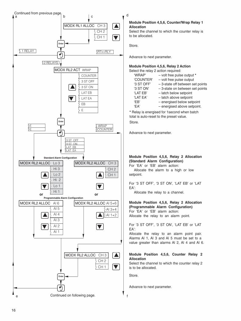
Module Position 4,5,6, Relay 2 Allocation(Standard Alarm Configuration)For ‘EA’ or ‘EB’ alarm action:
Allocate the alarm to a high or lowsetpoint.
For ‘3 ST OFF’, ‘3 ST ON’, ‘LAT EB’ or ‘LATEA’:
Allocate the relay to a channel.
Module Position 4,5,6, Relay 2 Allocation(Programmable Alarm Configuration)For ‘EA’ or ‘EB’ alarm action:Allocate the relay to an alarm point.
For ‘3 ST OFF’, ‘3 ST ON’, ‘LAT EB’ or ‘LATEA’:Allocate the relay to an alarm point pair.Alarms Al 1, Al 3 and Al 5 must be set to avalue greater than alarms Al 2, Al 4 and Al 6.
Advance to next parameter.
Advance to next parameter.
Module Position 4,5,6, Relay 2 ActionSelect the relay 2 action required: ‘WRAP’ – volt free pulse output *
‘COUNTER’ – volt free pulse output‘3 ST OFF’ – 3-state off between set points‘3 ST ON’ – 3-state on between set points‘LAT EB’ – latch below setpoint‘LAT EA’ – latch above setpoint‘EB’ – energised below setpoint‘EA’ – energised above setpoint.
Store.
Enter Store.
Advance to next parameter.
Module Position 4,5,6, Counter/Wrap Relay 1AllocationSelect the channel to which the counter relay isto be allocated.
Store.
Module Position 4,5,6, Counter Relay 2AllocationSelect the channel to which the counter relay 2is to be allocated.
Continued from previous page.
Continued on following page.
Standard Alarm Configuration
Programmable Alarm Configuration
a b c d
MODX RL2 ACT
3 ST ON
LAT EA
LAT EB
E
EB
COUNTER
3 ST OFF
WRAP
COUNTERWRAP
* Relay is energised for 1second when batchtotal is auto-reset to the preset value.
e f
MODX RL1 ALLOC CH 3

17
MODX RTx FS 20.0mA10.0
Enter Store.
Advance to next parameter.
Module Position 4,5,6, Retransmission FullScaleSet the maximum value required for theretransmission signal, adjustable in 0.1mAsteps in the range 10.0 to 20.0mA.
SET UP RTx OUTPUT
MODX RTx ZERO 10.0mA00.0
MODX RTx ALLOC CH 3
CH 2
CH 1
Enter
Enter
Enter
Enter
MOD X MIN O/P
MOD X MAX O/P
Enter
Store.
Advance to next parameter.
Store.
Advance to next parameter.
Store.
Advance to next parameter.
Module Position 4,5,6, Retransmission ZeroSet the minimum value required for theretransmission signal, adjustable in 0.1mAsteps in the range 00.0 to 10.0mA. Thisparameter is omitted on single peninstruments.
Module Position 4,5,6, RetransmissionAllocationSelect the channel to which the retransmissionsignal is to be allocated. This parameter isomitted on single pen instruments.
Module Position 4,5,6 RetransmissionMinimum OutputConnect a 0 to 20mA milliammeter to theappropriate module output connection andusing the ‘Raise’/‘Lower’ switches adjust themilliammeter displayed value to coincide withthe retransmission minimum signal specifiedabove.
Store.
Return to top of Set Up Modules Page.
Module Position 4,5,6, RetransmissionMaximum OutputUse the ‘Raise’/‘Lower’ switches to adjust themilliammeter displayed value to coincide withthe retransmission maximum signal specifiedabove.
Advance to next parameter.
Set Up Retransmission Output
Continued from previous page.
Store.
e f

18
9(F) SIMPLE FAULT FINDING
As detailed in Section 9 of IM/1492.
10(F) CALIBRATION
As detailed in Section 10 of IM/1492.

19
APPENDIXA1(F) Calculation of Pulse Rate and Total Count
Pulse Rate Convert full scale flow rate into units/second (1)
Pulse rate = —————— (2)
Counter factor i. e. what the first digit on counter represents
Example 1 Range: 0 to 100 m3/hour
Counter factor: 1m3
From (1) = ——— = 0.0278 m3/second
From (2) pulse rate = ——— = 0.0278 pulses/second
enter 0.028 at Counter FS
Example 2 Alternatively with Example 1 a counter factor of 0.1m3 could be set giving a pulse rate of 0.278 pulses/second.
The decimal point switch (see page 13) would be set to 10–1.
Example 3 Range: 0 to 1000 m3/minute
Counter factor: 1m3
From (1) = ——— = 16.67m3 /second
From (2) pulse rate = 16.67 = 16.67 pulses/second – this is too high
If counter factor = 10m3
∴Pulse rate = ——— = 1.667 pulses/second
enter 1.67 at Counter FS and set decimal point switch to give x10 factor (see page 13).
100060
16.67
10
0.02781
60 x 60100
units/secondcounter factor Must be within the limits of
10.00 to 0.001 pulses per second

20
Notes.

PRODUCTS & CUSTOMER SUPPORT
ProductsAutomation Systems
• for the following industries:– Chemical & Pharmaceutical– Food & Beverage– Manufacturing– Metals and Minerals– Oil, Gas & Petrochemical– Pulp and Paper
Drives and Motors• AC and DC Drives, AC and DC Machines, AC motors to 1kV• Drive systems• Force Measurement• Servo Drives
Controllers & Recorders• Single and Multi-loop Controllers• Circular Chart , Strip Chart and Paperless Recorders• Paperless Recorders• Process Indicators
Flexible Automation• Industrial Robots and Robot Systems
Flow Measurement• Electromagnetic Magnetic Flowmeters• Mass Flow Meters• Turbine Flowmeters• Wedge Flow Elements
Marine Systems & Turbochargers• Electrical Systems• Marine Equipment• Offshore Retrofit and Refurbishment
Process Analytics• Process Gas Analysis• Systems Integration
Transmitters• Pressure• Temperature• Level• Interface Modules
Valves, Actuators and Positioners• Control Valves• Actuators• Positioners
Water, Gas & Industrial Analytics Instrumentation• pH, conductivity, and dissolved oxygen transmitters and
sensors• ammonia, nitrate, phosphate, silica, sodium, chloride,
fluoride, dissolved oxygen and hydrazine analyzers.• Zirconia oxygen analyzers, katharometers, hydrogen purity
and purge-gas monitors, thermal conductivity.
Customer Support
We provide a comprehensive after sales service via aWorldwide Service Organization. Contact one of the followingoffices for details on your nearest Service and Repair Centre.
United KingdomABB LimitedTel: +44 (0)1453 826661Fax: +44 (0)1453 827856
United States of AmericaABB Inc.Tel: +1 (0) 755 883 4366Fax: +1 (0) 755 883 4373
Client Warranty
Prior to installation, the equipment referred to in this manualmust be stored in a clean, dry environment, in accordance withthe Company's published specification.
Periodic checks must be made on the equipment's condition. Inthe event of a failure under warranty, the followingdocumentation must be provided as substantiation:
1. A listing evidencing process operation and alarm logs at timeof failure.
2. Copies of all storage, installation, operating and maintenancerecords relating to the alleged faulty unit.

IM/1
492–
FWIs
sue
8
ABB LimtedHoward Road, St NeotsCambridgeshirePE19 8EUUKTel: +44 (0)1480 475 321Fax: +44 (0)1480 217 948
ABB Inc.125 E. County Line RoadWarminsterPA 18974USATel: +1 215 674 6000Fax: +1 215 674 7183
ABB has Sales & Customer Supportexpertise in over 100 countries worldwide
www.abb.com
The Company’s policy is one of continuous productimprovement and the right is reserved to modify the
information contained herein without notice.
Printed in UK (02.04)
© ABB 2004