dpharp brain communication type(ejx a, eja e)€¦ · user’s manual dpharp brain communication...
TRANSCRIPT

User’sManual DPharp
BRAIN Communication Type(EJXA, EJAE)
IM 01C25T03-01E
IM 01C25T03-01E8th Edition

Toc-1
IM 01C25T03-01E
DPharpBRAIN Communication Type
IM 01C25T03-01E 8th Edition
8th Edition: Nov. 2019 (YK)All Rights Reserved, Copyright © 2004, Yokogawa Electric Corporation
Contents1. Introduction ............................................................................................... 1-1
Regarding This Manual ................................................................................................1-11.1 Safe Use of This Product .................................................................................1-21.2 Warranty .............................................................................................................1-3
2. Connection ................................................................................................ 2-12.1 Connecting the BT200 ......................................................................................2-12.2 Communication Line Requirements ...............................................................2-12.3 Power Supply Voltage and Load Resistance ................................................. 2-22.4 Integral Indicator Display When Powering On .............................................. 2-2
3. Operation ................................................................................................... 3-13.1 BT200 Operating Procedures ..........................................................................3-1
3.1.1 Key Layout and Screen Display .........................................................3-13.1.2 Operating Key Functions ...................................................................3-1
(1) Alphanumeric Keys and Shift Keys ........................................... 3-1(2) Function Keys ............................................................................3-2
3.1.3 Calling Up Menu Addresses Using the Operating Keys .................... 3-33.1.4 Printout (for BT200 printer option) .....................................................3-3
(1) Printout of All Parameters ..........................................................3-3(2) Printout by Menu Item ...............................................................3-3
3.2 Setting Parameters Using the BT200 .............................................................3-43.2.1 Parameter Usage and Selection ........................................................3-43.2.2 Menu Tree ..........................................................................................3-53.2.3 Setting Parameters ............................................................................3-6
(1) Tag No. Setup ...........................................................................3-6(2) Calibration Range Setup ...........................................................3-6(3) Damping Time Constant Setup ................................................3-8(4) Output Mode and Integral Indicator Display Mode Setup ........ 3-8(5) Output Signal Low Cut Mode Setup ......................................... 3-8(6) Integral Indicator Scale Setup ...................................................3-9(7) Unit Setup for Displayed Temperature .................................... 3-11(8) Operation Mode Setup ........................................................... 3-11(9) Impulse Line Connection Orientation Setup .......................... 3-11(10) CPU Failure Burnout Direction and Hardware Write Protect .3-12

Toc-2
IM 01C25T03-01E
(11) Software Write Protect ............................................................3-12(12) Output Status Setup when a Hardware Error Occurs ............3-13(13) Bi-directional Flow Measurement Setup .................................3-13(14) Range Change while Applying Actual Inputs .........................3-14(15) Sensor Trim .............................................................................3-14(16) Test Output Setup ...................................................................3-18(17) Signal Characterizer ................................................................3-18(18) Process Alarm ........................................................................3-19(19) Status Output (option code AL) ...............................................3-20(20) Capillary Fill Fluid Density Compensation .............................3-21(21) Adjustment Information and User Memo Fields .....................3-22
3.3 Displaying Data Using the BT200 ..................................................................3-223.3.1 Displaying Measured Data...............................................................3-223.3.2 DisplayTransmitterModelandSpecifications .................................3-22
4. Self-diagnostics ........................................................................................ 4-14.1 Checking for Problems ....................................................................................4-1
4.1.1 Identifying Problems with BT200 ....................................................... 4-14.1.2 Checking with Integral Indicator .........................................................4-2
4.2 Alarms and Countermeasures ........................................................................4-2
5. Parameter Summary ................................................................................ 5-1Appendix 1. Safety Instrumented Systems Installation ............................A1-1Revision Information
<1. Introduction> 1-1
IM 01C25T03-01E
1. IntroductionThank you for purchasing the DPharp EJX series pressure transmitter/EJA series pressure transmitter (“transmitter”).
The transmitters are precisely calibrated at the factory before shipment. To ensure both safety and efficiency,pleasereadthismanualcarefullybeforeoperating the instrument.
This manual describes the BRAIN protocol communication functions of the transmitter and explains how to set the parameters for the transmitters using the BT200 handheld terminal. For information on the installation, wiring, and maintenance of the transmitters, please refer to the user’s manual of each model.
WARNING
When using the transmitters in a Safety Instrumented System application, refer to the Functional Safety Manual (Document No.: TI 01C25A05-01EN or TI 01C25A05-21EN for option code SLT) and follow the instructions and procedures described there.The document can be downloaded from the website of Yokogawa. (Website address: https://www.yokogawa.com/solutions/products-platforms/field-instruments/)In order to satisfy the requirement of Safety Instrumented System, executing parameters setting is required. Please refer to 3.2 “Setting Parameters Using the BT200” for setting range.Please also refer to the status output setting in the same clause. After installing the transmitter, confirmthattherangeandunitissetcorrectly.Calibration of the transmitters shall be done after completing the range setting.
Regarding This Manual• This manual should be provided on to the end
user.
• The contents of this manual are subject to change without prior notice.
• All rights reserved. No part of this manual may be reproduced in any form without Yokogawa’s written permission.
• Yokogawa makes no warranty of any kind with regard to this manual, including, but not limited to, implied warranty of merchantability and fitnessforaparticularpurpose.
• If any question arises or errors are found, or if any information is missing from this manual, please inform the nearest Yokogawa sales office.
• Thespecificationscoveredbythismanualarelimited to those for the standard type under the specifiedmodelnumberbreak-downanddonotcover custom-made instruments.
• Pleasenotethatchangesinthespecifications,construction, or component parts of the instrumentmaynotimmediatelybereflectedin this manual at the time of change, provided that postponement of revisions will not cause difficultytotheuserfromafunctionalorperformance standpoint.
• The following safety symbols are used in this manual:
WARNING
Indicates a potentially hazardous situation which, if not avoided, could result in death or serious injury.
CAUTIONIndicates a potentially hazardous situation which, if not avoided, may result in minor or moderate injury. It may also be used to alert against unsafe practices.
IMPORTANTIndicates that operating the hardware or software in this manner may damage it or lead to system failure.
NOTEDraws attention to information essential for understanding the operation and features.

<1. Introduction> 1-2
IM 01C25T03-01E
1.1 Safe Use of This Product For the safety of the operator and to protect the instrument and the system, please be sure to follow this manual’s safety instructions when handling this instrument. If these instructions are not heeded, the protection provided by this instrument may be impaired. In this case, Yokogawa cannot guarantee that the instrument can be safely operated. Please pay special attention to the following points:
(a) Installation
• This instrument may only be installed by an engineer or technician who has an expert knowledge of this device. Operators are not allowed to carry out installation unless they meet this condition.
• With high process temperatures, care must be taken not to burn yourself by touching the instrument or its casing.
• Never loosen the process connector nuts when the instrument is installed in a process. This can lead to a sudden, explosive release of process fluids.
• When draining condensate from the pressure detector section, take appropriate precautions to prevent the inhalation of harmful vapors and thecontactoftoxicprocessfluidswiththeskinor eyes.
• When removing the instrument from a hazardous process, avoid contact with the processfluidandtheinteriorofthemeter.
• All installation shall comply with local installation requirements and the local electrical code.
(b) Wiring
• The instrument must be installed by an engineer or technician who has an expert knowledge of this instrument. Operators are not permitted to carry out wiring unless they meet this condition.
• Before connecting the power cables, please confirmthatthereisnocurrentflowingthroughthe cables and that the power supply to the instrumentisswitchedoff.
(c) Operation
• Wait10min.afterthepoweristurnedoff,beforeopening the covers.
(d) Maintenance
• Please carry out only the maintenance procedures described in this manual. If you require further assistance, please contact the nearestYokogawaoffice.
• Care should be taken to prevent the build up of dust or other materials on the display glass and the name plate. To clean these surfaces, use a soft, dry cloth.
(e) Modification
• Yokogawa will not be liable for malfunctions or damageresultingfromanymodificationmadeto this instrument by the customer.

<1. Introduction> 1-3
IM 01C25T03-01E
1.2 Warranty• The warranty shall cover the period noted on
the quotation presented to the purchaser at the time of purchase. Problems occurring during the warranty period shall basically be repaired free of charge.
• If any problems are experienced with this instrument, the customer should contact the Yokogawa representative from which this instrument was purchased or the nearest Yokogawaoffice.
• If a problem arises with this instrument, please inform us of the nature of the problem and the circumstances under which it developed,includingthemodelspecificationand serial number. Any diagrams, data and other information you can include in your communication will also be helpful.
• Thepartyresponsibleforthecostoffixingtheproblem shall be determined by Yokogawa following an investigation conducted by Yokogawa.
• The purchaser shall bear the responsibility for repair costs, even during the warranty period, if the malfunction is due to:
- Improper and/or inadequate maintenance by the purchaser.
- Malfunction or damage due to a failure to handle, use, or store the instrument in accordancewiththedesignspecifications.
- Use of the product in question in a location notconformingtothestandardsspecifiedbyYokogawa, or due to improper maintenance of the installation location.
- Failureordamageduetomodificationorrepair by any party except Yokogawa or an approved representative of Yokogawa.
- Malfunction or damage from improper relocation of the product in question after delivery.
- Reasonofforcemajeuresuchasfires,earthquakes,storms/floods,thunder/lightening, or other natural disasters, or disturbances, riots, warfare, or radioactive contamination.

<2. Connection> 2-1
IM 01C25T03-01E
2. ConnectionThe BRAIN communication signal is superimposed onto the 4 to 20 mA DC analog signal. Since the modulated wave is a communication signal, superimposing it on the normal signal will, from basic principles, cause no error in the DC component of the analog signal. Thus, monitoring can be performed via the BT200 while the transmitter is on-line.
2.1 Connecting the BT200
IMPORTANTAnalog output may change temporally in connecting with BRAIN terminal due to an initial currentflowedtoit.Topreventcommunicationsignalaffectingtheuppersystem,itisrecommendedtoinstallalow-passfilter(approximately 0.1s)
Connection to the transmitter with the BT200 can be made by either connecting to the BT200 connection hooks in the transmitter terminal box or by connecting to a relaying terminal or a terminal board.
Relaying terminals
Distributor
Control room
Terminal board
F0201.ai
Figure 2.1 Connecting the BT200
2.2 Communication Line Requirements
[Protocolspecification]Yokogawaoriginalprotocol
[Modulation]Burstmodulation 0: 2400Hz 1: Signal without carrier
[Baudrate]1200bps
[Communicationsignal]
hosttodevice:+/-0.5V(loadresistance250Ω)
device to host: +/- 2mA
DPharp
BT200
Cable resistance Rc
Cable resistance Rc
Load resistance R
ccPower supply
Loop resistance = R + 2Rc = 250 to 600 Ω Loop capacitance = 0.22 µF max.
F0202.ai
Figure 2.2 Communication Line Requirements

<2. Connection> 2-2
IM 01C25T03-01E
2.3 Power Supply Voltage and Load Resistance
Whenconfiguringtheloop,makesurethattheexternal load resistance is within the range in the figurebelow.(Note) With an intrinsically safe transmitter, external load
resistance includes safety barrier resistance.
600
250
0 10.5 16.6 25.2 42
External load
resistanceR (Ω)
Power supply voltage E (V DC)F0203.ai
Communication applicable range
R= E–10.50.0244
Figure 2.3 Relationship between Power Supply Voltage and External Load Resistance
2.4 Integral Indicator Display When Powering On
For models with the integral indicator code “D”, the display shows all segments in the LCD and then changes to the displays shown below sequentially.
All segments display Model name (3 s)
Communication Protocol (3 s) – – – – (3 s) F0200.ai
NOTEFor output signal code “D”, this function is available for software revision 2.02 or later.Software revision can be checked by the parameter M15: SOFT REV.Refer to section 3 “Operation” how to call up the parameter.
NOTELCD display can be set to all segments display only by the parameter I41: POWER ON INF.
ON Show All segments display, Model name and Communication Protocol when powering on.
OFF Show All segments display when powering on.
Refer to section 3 “Operation” how to call up the parameter.

<3. Operation> 3-1
IM 01C25T03-01E
3. OperationThe transmitter is equipped with BRAIN communications capabilities, so that range changes, Tag No. setup, monitoring of self-diagnostic results, and zero point adjustment can be handled remotely via the BT200 BRAIN TERMINAL, the FieldMate Versatile Device Management Wizard or the CENTUM CS console. This section describes procedures for setting parameters using the BT200. For further information on the BT200, see the BT200 User’s Manual (IM 01C00A11-01E).
IMPORTANTCommunication signal is superimposed on analog output signal. It is recommended to set alow-passfilter(approximately0.1s)tothereceiverinordertoreducetheoutputeffectfrom communication signal. Before online-communication,confirmthatcommunicationsignaldoesnotgiveeffectontheuppersystem.
3.1 BT200 Operating Procedures3.1.1 Key Layout and Screen DisplayFigure 3.1 shows the arrangement of the operating keysontheBT200keypad,andfigure3.2showsthe BT200 screen.
F0301.ai
LCD(21 characters × 8 lines)
Movement keys
Power ON/OFF key
Function keys
ENTER key
Alphanumeric keys
Shift keys
Figure 3.1 BT200 Key Layout
PARAM A10:OUTPUT 0.0 % A11:PRES 0.0000 kPa A15:OUTPUT mA 4.000 mA
Menu choices
MessagesMENU SCREEN
Screen title
MENU A:DISPLAY B:SENSOR TYPE C:BASIC SETUP D:AUX SET1 E:AUX SET2 G:ALARM SET
BATTERY
HOME SET ADJ ESC
Functioncommands
PARAMETER SCREEN
Parameters
DATA DIAG PRNT ESC
F0302.ai
Figure 3.2 BT200 Screen
3.1.2 Operating Key Functions
(1) Alphanumeric Keys and Shift KeysUse the alphanumeric keys in conjunction with the shift keys to enter numbers, symbols, and alphabetic characters.
Shift keys
Alphanumeric keys
F0303.ai
a. Entering Numbers, Symbols, and Spaces
Simply press the alphanumeric keys.
Entry Key-in sequence
–4
0.3
1 –9F0304.ai

<3. Operation> 3-2
IM 01C25T03-01E
b. Entering Alphabetic CharactersPress either the left or right shift key and then an alphanumeric key to enter the desired alphabetic character. The shift key must be pressed each time an alphabetic character is entered.
Entry Key-in sequence
W
IC
J. BF0305.ai
Letter on left side of the alphanumeric key
Letter on right side of the alphanumeric key
Usethefunctionkey[F2] CAPS to select uppercase and lowercase (for alphabetic characters only). The case toggles between uppercase and lowercaseeachtime[F2]CAPSispressed.
Entry
Boy
Key-in sequence
F0306.ai
CODE CAPS CLR ESC
Entering uppercase
CODE caps CLR ESC
Entering lowercase
( B ) ( y )( o )
to lower case
Usethefunctionkey[F1] CODE to enter symbols. The following symbols will appear in sequence, oneatatime,atthecursoreachtime[F1]CODEispressed:
/ . – , + * ) ( ’ & % $ # ” !
To enter characters next to these symbols, press [>]tomovethecursor.
( / )
Entry
l/m
Key-in Sequence
F0307.ai
( m )( I )
symbol command
(2) Function KeysThe function command carried out by each function key is displayed directly above the key.
MENU A:DISPLAY B:SENSOR TYPE C:BASIC SETUP D:AUX SET1 E:AUX SET2 G:ALARM SETHOME SET ADJ ESC Function commands
Function keysF0308.ai
Function Command List
Command FunctionADJ Displays the ADJ menuCAPS/caps Selects uppercase or lowercaseCODE Selects symbolsCLR Erases input data or deletes all dataDATA Updates parameter dataDEL Deletes one characterDIAG Calls the self-check panelESC Returns to the most recent displayHOME Displays the menu panelNO Quits setup and returns to the previous
displayOK Proceeds to the next panelPRAM Enters the parameter number setup
modeSET Displays the SET menuSLOT Returns to the slot selection panelUTIL Calls the utility panel*COPY Prints out parameters on display*FEED Paper feed*LIST Lists all parameters in the menu*PON/POFF Automaticprintoutmodeonoroff*PRNT Changes to the print mode*GO Starts printing*STOP Cancels printing
* Available on BT200-P00 (with printer).

<3. Operation> 3-3
IM 01C25T03-01E
3.1.3 Calling Up Menu Addresses Using the Operating Keys
DATA DIAG PRNT ESC
PARAM A60:SELF CHECK GOOD
CODE CAPS CLR ESC
--WELCOME--BRAIN TERMINAL ID: BT200
check connection push ENTER key
UTIL FEED esc
PARAM 01:MODEL EJX110A-DM 02:TAG NO. YOKOGAWA 03:SELF CHECK GOOD
OK
STARTUPSCREEN
UTILITY SCREEN
FUNCTION SCREEN
MENUSCREEN
SETUPSCREEN
INITIAL DATA SCREEN
PARA-METER SCREEN
(HOME MENU SCREEN) (SET MENU SCREEN) (ADJ MENU SCREEN)
See the BT200 user’s manual for details concerning uploadingand downloading parameters and printouts (BT200-P00).
(UTIL)
(SET)
(ESC)
HOME SET ADJ
(ADJ)
The utility screen contains the following items.1. BT200 ID settings2. Security code settings3. Switching language of messages (Japanese or English)4. LCD contrast setting5. Adjusting printout tone (BT200-P00 only)
FUNC 1.MENU 2.UPLOAD TO HHT 3.DOWNLOAD TO INST 4.PRINT ALL DATA
HOME SET ADJ ESC
MENU A:DISPLAY B:SENSOR TYPE C:BASIC SETUP D:AUX SET1 E:AUX SET2 G:ALARM SET
HOME SET ADJ ESC
MENU C:BASIC SETUP D:AUX SET 1 E:AUX SET 2 G:ALARM SET H:AUTO SET I:DISP SET
HOME SET ADJ ESC
MENU J:ADJUST K:TEST M:DEVICE INFO P:RECORD T:CHARACTERIZR
DATA DIAG PRNT ESC
DATA DIAG PRNT ESC DATA DIAG PRNT ESC
PARAM C60:SELF CHECK GOOD
PARAM C22:PRES URV 100.00 kPa C23:PRES POINT DATA DIAG PRNT ESC
DATA DIAG PRNT ESC
PARAM J60:SELF CHECK GOOD
PARAM J12:P SPAN ADJ 100.000 % J15:P ZERO DEV
DATA DIAG PRNT ESC
PARAM J09:ADJ UNIT % J10:ADJ PRES 0.02563 % J11:P ZERO ADJ 0.04792 %
SET C10:TAG NO. YOKOGAWA YOKOGAWA
F0309.ai
DATA DIAG PRNT ESC
PARAM A10:OUTPUT 0.0 % A11:PRES 0.0000 kPa A15:OUTPUT mA 4.000 mA
DATA DIAG PRNT ESC
PARAM C10:TAG NO. YOKOGAWA C20:PRES UNIT kPa C21:PRES LRV 0.00000 kPa
PARAM A16:ENGR.OUTPUT 0.0000 mmHg A17:ENGR.EXP
UTILITY 1.ID 2.SECURITY CODE 3.LANGUAGE SELECT 4.LCD CONTRAST 5.PRINTER ADJUST
3.1.4 Printout (for BT200 printer option)
(1) Printout of All ParametersSelect 4. PRINT ALL DATA from the function screen to output a list of all parameters. It takes about 10 minutes to complete the printout.
(2) Printout by Menu ItemToprintouttheparametersforaspecificscreen,push the function key corresponding to screen’s PRNT.

<3. Operation> 3-4
IM 01C25T03-01E
3.2 Setting Parameters Using the BT200
3.2.1 Parameter Usage and SelectionBefore setting a parameter, please see the following table for a summary of how and when each parameter is used.
Table 3.1 Parameter Usage and SelectionSetup item Description
TagNo.setup P.3-6 Sets the Tag No. (using 16 alphanumeric characters).Calibration range setup P.3-6
Sets the calibration range for 4 to 20 mA DC. Sets the following items: range unit, input value at 4 mA DC (LRV), input value at 20 mA DC (URV), and decimal point position.Note:LRVandURVcanbespecifiedwithrangevaluespecificationsupto5digits(excludingany
decimal point) within the range of –32000 to 32000.Damping time constant setup P.3-8
Adjuststheoutputresponsespeedfor4to20mADCatamplifier.Can be set from 0.50 to 100.00 s. (from 0.00 to 100.00 s with quick response mode on)
Output and integral indicator display mode setup P.3-8
SetsmodesforoutputsignalandintegralindicatortoLinearmode(proportionaltoinputdifferentialpressure)ortoSquarerootmode(proportionaltoflow).
Output signal low cut mode setup P.3-8
Used mainly to stabilize output near 0% if the output signal is square root mode.Twomodesareavailable:forcingoutputto0%forinputbelowaspecificvalue,orchangingtoproportionaloutputforinputbelowaspecificvalue.
Integral indicator display function P.3-9
Available from the following 5 types of integral indicator scale ranges and units: input pressure, % of range, user set scale, input static pressure, % of static pressure range, and
alternating among any four of the above.Configurethefollowingwhenusingtheusersetscale; user set scale setting, unit (BT200 only), display value at 4 mA DC (LRV), and display value at
20 mA DC (URV).Note:LRVandURVcanbespecifiedwithrangevaluespecificationsupto5digits(excludingany
decimal point) within the range of –32000 to 32000.Static pressure setup P.3-11
Sets the parameters concerned with static pressure such as unit, calibration range, upper and lower range values, decimal point position, damping time constant.
Unit setup for displayed temperature P.3-11
Sets the unit for temperatures displayed on the BT200.
Operation mode (normal/reverse signal) setup P.3-11
Reverses the direction for 4 to 20 mA DC output relative to input.Reverse mode is used for applications in which safety requires that output be driven toward 20 mA if input is lost.
Impulse line connection orientation (higher pressure on right/left side) setup P.3-11
Used where installation conditions make it imperative to connect high pressure side impulse line to low pressure side of transmitter. Reversal of orientation should be dealt with by reversing impulse line wherever possible. Use this function only where there is no alternative.
CPU Failure burnout direction and hardware write protect P.3-12
Displays the status of 4 to 20 mA DC output when a CPU fails. The direction is selectable by the hardwareswitchontheamplifier.Italsophysicallypreventsparameteraccess
Software write protect P.3-12 Configureddatacanbeprotectedbysettingapassword.Output status setup when a hardware error occurs P.3-13
Sets the status of the 4 to 20 mA DC output when an abnormal status is detected with the capsule ortheamplifierastheresultofself-diagnosis.Eitherthelastheld,highlimit,orlowlimitvaluesstatus, can be selected.
Bi-directionalflowmeasurement P.3-13
Usedtomeasurebi-directionalflows.Outputatzeroflowis12mADC,withoutputrangeequallydividedbetweenforwardandreverseflow.Canbeusedwithsquarerootmode.
Range change while applying actual inputs P.3-14
Range for 4 to 20 mA DC signal is set with actual input applied. Sets 20 mA DC output precisely with respect to user’s reference instrument output. Note that the transmitter is calibrated with high accuracy before shipment, so span should be set using the normal range setup.
Sensor trim P.3-14 Adjusts zero point and span of the sensor.Testoutput(fixedcurrentoutput)setup P.3-18
Used for loop checks.Output can be set freely from –2.50% to 110.00% in 0.01% steps.
Signal characterizer P.3-18 Used to compensate the output for the non-linear application.Process alarm P.3-19 Used for alarm generation on the integral indicator.Status output P.3-20 Outputsanon/offdigitalsignalbasedonthesettingsofprocessalarm.Capillaryfillfluiddensitycompensation P.3-21
Compensatesthezeroshiftbytheambienttemperatureeffectonthecapillarytubes.
Usermemofields P.3-22
Allows user to enter up to 3 items, each containing any combination of up to 16 alphanumeric characters.
IMPORTANTAfter setting and sending data with the BT200,wait30secondsbeforeturningoffthetransmitter.Ifitisturnedofftoosoon,thesettingswill not be stored in the transmitter.

<3. Operation> 3-5
IM 01C25T03-01E
3.2.2 Menu Tree
A: DISPLAYHOME
A10: OUTPUTA11: PRESA15: OUTPUT mAA16: ENGR. OUTPUTA17: ENGR. EXPA20: SP %*1
A21: SP*1
A30: CAPSULE TEMPA60: SELF CHECK
B10: MODELB11: STYLE NO.B20: PRES LRLB21: PRES URLB22: P MIN SPANB30: SP LRL*1
B31: SP URL*1
B32: SP MIN SPAN*1
B60: SELF CHECK
C: BASIC SETUP
C10: TAG NO.C20: PRES UNITC21: PRES LRVC22: PRES URVC23: PRES POINTC30: AMP DAMPINGC40: OUTPUT MODEC60: SELF CHECK
D10: LOW CUTD11: LOW CUT MODED15: H/L SWAP*1
D16: H2O UNIT SELD20: OUT LIMIT(L)D21: OUT LIMIT(H)D22: REV OUTPUTD25: BURNOUTD26: ERROR OUTD30: SP UNIT*1
D31: SP A/G SLCT*1
D32: ATM. PRESS*1
D33: SP LRV*1
D34: SP URV*1
D35: SP POINT*1
D36: SP DAMPING*1
D37: SP SELECT*1
D40: TEMP UNITD50: QUICK RESPD55: WRT PROTECTD56: WRT ENABLED57: NEW PASSWORDD58: SOFTWR SEALD60: SELF CHECK
E10: T. ZERO CMPE11: TEMP ZEROE30: BI DIRE MODEE50: DO SELECT*2
E51: DO SIG.TYPE*2
E52: D OUTPUT*2
E60: SELF CHECK
G10: P AL MODEG11: P HI. AL VALG12: P LO. AL VALG20: SP AL MODE*1
G21: SP HI. AL VAL*1
G22: SP LO. AL VAL*1
G30: T AL MODEG31: T HI. AL VALG32: T LO.AL VALG50: AUTO RECOVERG60: SELF CHECK
H10: AUTO P LRVH11: AUTO P URVH20: AUTO SP LRV*1
H21: AUTO SP URV*1
H60: SELF CHECK
I10: DISP OUT1I11: DISP OUT2I12: DISP OUT3I13: DISP OUT4I20: P DISP MODEI21: PRES % RESOI30: ENGR. UNITI31: EASY EU SETI32: ENGR. EXPI33: ENGR. LRVI34: ENGR. URVI35: ENGR. POINTI40: BAR INDICATRI41: POWER ON INF*3
I60: SELF CHECK
J09: ADJ UNITJ10: ADJ PRESJ11: P ZERO ADJJ12: P SPAN ADJJ15: P ZERO DEVJ16: P SPAN DEVJ20: ADJ SP*1
J21: SP ZERO ADJ*1
J22: SP SPAN ADJ*1
J25: SP ZERO DEV*1
J26: SP SPAN DEV*1
J40: OUTPUT 4mAJ41: OUTPUT 20mAJ45: AMP TEMPJ50: ADJ WHOJ51: ADJ DATEJ52: ADJ LOCJ53: ADJ DESCJ55: EXT ZERO ADJJ56: CLEAR ADJJ60: SELF CHECK
K10: OUTPUT X %K40: DO TEST*2
K45: TEST TIME*3
K50: TEST KEY1K51: TEST KEY2K52: TEST KEY3K53: TEST KEY4K60: SELF CHECK
M10: SERIAL NO.M11: MFTR. DATEM12: EXTRA NO.M15: SOFT REVM16: BRAIN REVM17: MEMO1M18: MEMO2M19: MEMO3M20: ISOL MATLM21: FILL FLUIDM22: GASKET MATLM23: PRO CON MATLM24: D-VENT MATLM25: PRO CON TYPEM26: RS ISOL MATLM27: PRO CON SIZEM28: NUM RSM29: RS FILL FLIDM30: RS TYPEM50: MS CODE 1M51: MS CODE 2M52: MS CODE 3M53: MS CODE 4M54: MS CODE 5M55: MS CODE 6M60: SELF CHECK
P10: ERROR REC 1P12: ERROR REC 2P14: ERROR REC 3P16: ERROR REC 4P50: REC CLEARP60: SELF CHECK
T10: S. C. ENABLET11: NUM OF POINTT20: X START (FIX)T21: Y START (FIX)T22: X1T23: Y1T24: X2T25: Y2T26: X3T27: Y3T28: X4T29: Y4T30: X5T31: Y5T32: X6T33: Y6T34: X7T35: Y7T36: X8T37: Y8T38: X9T39: Y9T40: X END (FIX)T41: Y END (FIX)T60: SELF CHECK
B: SENSOR TYPE
D: AUX SET 1 E: AUX SET2 G: ALARM SET H: AUTO SET I: DISP SET
J: ADJUST K: TEST M: DEVICE INFO P: RECORD T: CHARACTERIZR
SET
ADJ
F0310.ai*1: Available for differential pressure transmitter.*2: Available for EJX series only.*3: Available for software revision 2.02 or later. Software revision can be checked by the parameter M15: SOFT REV.

<3. Operation> 3-6
IM 01C25T03-01E
3.2.3 Setting ParametersSet or change the parameters as necessary. After completing these, do not fail to use the “DIAG” key toconfirmthat“GOOD”isdisplayedfortheself-diagnostic result at _60: SELF CHECK.
(1) Tag No. Setup (C10: TAG NO)
Use the procedure below to change the Tag No. Up to 16 alphanumeric characters can be entered.
Press the key to turn on the BT200.
Connect the transmitter and BT200 using a communication cable and press the key.
PARAM 01:MODEL EJX 02:TAG NO. YOKOGAWA 03:SELF CHECK GOOD
OK
MENU A:DISPLAY B:SENSOR TYPE C:BASIC SETUP D:AUX SET1 E:AUX SET2 G:ALARM SETHOME SET ADJ ESC
MENU C:BASIC SETUP D:AUX SET 1 E:AUX SET 2 G:ALARM SET H:AUTO SET I:DISP SETHOME SET ADJ ESC
MENU C10:TAG NO. YOKOGAWA C20:PRES UNIT kPa C21:PRES LRV 0.00000 kPaDATA DIAG PRNT ESC
<When power is off>
Select C: BASIC SETUP and press the key.
Select C10: TAG NO. and pressthe key.
Displays the model name of connected transmitter, TAG NO. and diagnostics information. Press the (OK) key after confirmation.
Press the (SET) key to display the SET menu panel.
--WELCOME--BRAIN TERMINAL ID: BT200
check connection push ENTER key
UTIL FEED
F0311_1.ai
SET C10:TAG NO. YOKOGAWA YOKOGAWA
CODE CAPS CLR ESC
When you have made an entry mistake, return the cursor using the key, then reenter.
Set the new TAG NO. (FIC-1a).FOKOGAWA
FIKOGAWA
FICOGAWA
FIC-GAWA
FIC-1AWA
FIC-1aWA
FIC-1a
Set TAG NO. and press the key.
SET C10:TAG NO. YOKOGAWA FIC-1a _
CODE caps CLR ESC
• Example: Set a Tag No. to FIC-1a
SET C10:TAG NO. FIC-1a
FEED NO OK
DATA DIAG PRNT ESC
This is the panel for confirming set data. The set data items flash.When all items have been confirmed, press theagain. (To go back to the setting panel, press the (NO) key.
SET C10:TAG NO. YOKOGAWA FIC-1a
print off F2:printer on
PARAM C10:TAG NO. FIC-1a C20:PRES UNIT kPa C21:PRES LRV 0.00000 kPa
FEED POFF NO
The DPharp TAG NO. was overwritten.Press the (OK) key to return to the parameter panel.Press the (NO) key to return to the setting panel.
F0311_2.ai
(2) Calibration Range Setup
a. Setting Calibration Range Unit (C20: PRES UNIT)
The unit parameter is set at the factory before shipmentifspecifiedatthetimeoforder.Followtheprocedure below to change the unit parameter.
• Example: Change the unit from mmH2O to kPa.
ESC
SET C20:PRES UNIT kPa
FEED NO OK
SET C20:PRES UNIT mmH2O < mmWG > < mmHg > < Torr > < kPa >
Use the or key to select kPa.Press the key twice to enter the setting.
Press the (OK) key.
F0312.ai
Note that the Yokogawa default setting for the standard temperature is 4°C (39.2°F). For the units of mmH2O, mmAq, mmWG, inH2O, and ftH2O, the pressure varies according to the standardtemperaturedefinition.Whenastandardtemperature of 20°C (68°F) is required, select @20degC (68.0F) at the parameter D16:H2O UNIT SEL.
Available pressure units are shown below.
mmH2OmmAqmmWGmmHgTorrkPa
MPambarbargf/cm2kgf/cm2inH2O
inHgftH2OpsiatmPahPa

<3. Operation> 3-7
IM 01C25T03-01E
b. Setting Calibration Range Lower Range Value and Upper Range Value (C21: PRES LRV, C22: PRES URV)
Theserangevaluesaresetasspecifiedintheorder before the instrument is shipped. Follow the procedure below to change the range.
The measurement range setting is used for correlating the 4-20 mA signal with the pressure value, therefore setting the measurement range in the safety instrumentation system is the setting of safety related parameters, and entering incorrect values may lead to dangerous events. When the pressure is over the range, output signal is saturated only within the normal operation range between the upper range value(URV) and the lower range value(LRV), and the 4 to 20 mA output does not enter the burnout state. Behaviors under “pressure over range” are not intended for behavior in safety instrumented systems.
“Pressure over range” of EJX/EJA is available as an alarm, not related to safety, via communication function or LCD display.
• The measurement span is determined by the upper and lower range limit values. In this instrument, changing the lower range value also automatically changes the upper range value, keeping the span constant.
• Example 1: With present settings of 0 to 30 kPa, set the lower range value to 0.5 kPa.
Span = Upper range value – Lower range value
FEED NO OK
SET C21:PRES LRV 0.5 kPa
DATA DIAG PRNT ESC
PARAM C20:PRES UNIT kPa C21:PRES LRV 0.5 kPa C22:PRES URV 30.5 kPa
DEL CLR ESC
SET C21:PRES LRV 0 kPa + 0.5
The upper range value is changed while the span remains constant.
Set 0.5.Press the key twice to enter the setting.
Press the (OK) key.
F0313.ai
• Entering the range values as LRV>URV reverses the direction of the output signal of 4-20 mA to 20-4 mA corresponding to the calibration range of 0 to 100%.
• Calibrationrangecanbespecifiedwithrangevaluespecificationsupto5digits(excludingany decimal point) for lower or upper range limits within the range of –32000 to 32000.
• Note, however, that changing the upper range value does not cause the lower range value to change. Thus, changing the upper range value also changes the span.
• Example 2: With present settings of 0 to 30 kPa, set the upper range value to 10 kPa.
FEED NO OK
SET C22:PRES URV 10 kPa
DATA DIAG PRNT ESC
PARAM C20:PRES UNIT kPa C21:PRES LRV 0 kPa C22:PRES URV 10 kPa
DEL CLR ESC
SET C22:PRES URV 30 kPa + 10
The lower range value is not changed, so the span changes.
Set 10.Press the key twice to enter the setting.
F0314.ai
Press the (OK) key.

<3. Operation> 3-8
IM 01C25T03-01E
(3) Damping Time Constant Setup (C30: AMP DAMPING)
When the instrument is shipped, the damping time constant is set at 2.00 seconds unless otherwise specifiedintheorder.Followtheprocedurebelowto change the damping time constant.
Note that setting the quick response parameter (D50: QUICK RESP) ON enables you to set the damping time constant between 0.00 to 0.49 second.
• Example: Change from 2.00 to 4.00 seconds.
ESCCLR
SET C30:AMP DAMPING 4.00 sec
FEED NO OK
SET C30:AMP DAMPING 2.00 sec + 004.00
Enter 4.Press the key twice to enter the setting.
F0315.ai
Press the (OK) key.
Note 1: The damping time constant set here is the time constantfortheamplifierassembly.Thedampingtimeconstant for the entire transmitter is the sum of the valuesfortheamplifierassemblyandforthecapsuleassembly.
Note 2: When the damping time constant is set to less than 0.5 second, communication may occasionally be unavailble during the operation, especially while output changes dynamically.
(4) Output Mode and Integral Indicator Display Mode Setup (C40: OUTPUT MODE, I20: P DISP MODE)
The mode setting for the output signal and the integral indicator can be performed independently.
Thismodeissetasspecifiedintheorderwhentheinstrument is shipped. Follow the procedure below to change the mode.
If the instrument is equipped with an integral indicator and the display mode is SQUARE ROOT, “ ” is displayed on the integral indicator.
• Output mode for 4-20 mA output
• Example: Set output mode from Linear to Square root.
ESC
SET C40:OUTPUT MODE SQUARE ROOT
FEED NO OK
SET C40:OUTPUT MODE LINEAR < LINEAR > < SQUARE ROOT >
Use the or key
to select SQUARE ROOT.
Press the key twice to
enter the setting.
Press the (OK) key.
F0316.ai
• Integral indicator display mode
• Example: Set display mode from Linear to Square root.
ESC
SET I20:P DISP MODE SQUARE ROOT
FEED NO OK
SET I20:P DISP MODE LINEAR < LINEAR > < SQUARE ROOT >
Use the or key
to select SQUARE ROOT.
Press the key twice to
enter the setting.
Press the (OK) key.
F0317.ai
(5) Output Signal Low Cut Mode Setup (D10: LOW CUT, D11: LOW CUT MODE)
Low cut mode can be used to stabilize the output signal near the zero point. The low cut point can be set in a range from 0 to 20%, the direct ratio corresponding to the output signal of 4 to 20 mA. (Hysteresis: ±10% of the cut point)
Either LINEAR or ZERO can be selected as the low cutmode.Unlessotherwisespecified,thecutmodeis set to LINEAR at the factory.
Note that when the output modes of the output signal and the integral indicator are selected as SQUARE ROOT and LINEAR accordingly, the low cut function is not available for the integral indicator display.

<3. Operation> 3-9
IM 01C25T03-01E
• Example: Change the low cut setting range from 10% to 20%, and the low cut mode from LINEAR to ZERO in the SQUARE ROOT output mode.
FEED NO OK
SET D11:LOW CUT MODE ZERO
Use the or key
to select ZERO.
Press the key twice to
enter the setting.
Press the (OK) key.
F0318.ai
FEED NO OK
SET D10:LOW CUT 20.00 %
ESC
SET D11:LOW CUT MODE LINEAR < LINEAR > < ZERO >
DATA DIAG PRNT ESC
PARAM D10:LOW CUT 20.0 % D11:LOW CUT MODE ZERO D15:H/L SWAP NORMAL
CLR ESC
SET D10:LOW CUT 10.00 % + 20.00
Set 20.
Press the key twice to
enter the setting.
Press the (OK) key.
Next, the [D11: LOW CUT MODE]
setting panel is displayed.
(%)50
20
0 50 (%)
Output
Low cut mode “LINEAR”
Input
(%)50
20
0 50 (%)
Low cut mode “ZERO”
LOW CUT at 20%
Input
The low cut point has hysteresis so that the output aroundthepointisbehavedasbelowfigure.
<Example> Output mode: Linear Low cut mode: Zero Low cut: 20.00%
F0319.ai
Setting range: 0 to 20%
2% 2%4mA
Output Low cut point
Input
Hysteresis fixed at 10%of the cut point
7.2mA(20%)
(6) Integral Indicator Scale SetupThefollowingfivedisplaysareavailableforintegralindicators: input pressure*1, % of range, user set scale, input static pressure, and % of static pressure range*1. A cycle of up to four displays can be shown by assigning variables to the parameters I10 to I13: DISP OUT1 to DISP OUT4.
F0320.ai
Available displays
Input pressure(PRES)
% of range(PRES %)
User set scale(ENGR. PRES)
Input static pressure(SP)*1
% of static pressure range(SP %)*1
Indicates values of input pressurewith the indication limits -32000 to 32000.
Indicates input pressure in -2.5 to 110% range depending on the measuring range (C21, C22).
Indicates values depending on the engineering range (I33, I34) with the unit (I30).
Indicates input static pressure with the indication limits -32000 to 32000.Reference pressure is factory-set in absolute.
Indicates input static pressure in -10 to 110% range depending on the measuring range (D33, D34).
A11:PRES
456 kPa
Descriptionand related parameters
A10:OUTPUT
45.6 %
A16:ENGR.OUTPUT
20.5 m3/min
A17:ENGR.EXP
×100
A21:SP
4.000 MPa
A20:SP %
52.6 %
*1: Available for differential pressure transmitter.
See (a.) through (d.) for each setting procedure.

<3. Operation> 3-10
IM 01C25T03-01E
a. Display Selection (I10: DISP OUT1)
Select the variable for the parameter I10: DISP OUT1 to display on the integral indicator.
• Example: Change the integral indicator scale from % of range to input pressure display.
ESC
SET I10:DISP OUT1 PRES
FEED NO OK
Use the or key
to select PRES.
Press the key twice to
enter the setting.
Press the (OK) key.
F0321.ai
SET I10:DISP OUT1 PRES % < PRES > < PRES % > < ENGR.PRES > < SP >
b. Cyclic Display (I11: DISP OUT2, I12: DISP OUT3, and I13: DISP OUT4)
In addition to the display set at I10: DISP OUT1, displays can be set at I11: DISP OUT2, I12: DISP OUT3, and I13: DISP OUT4 for cyclic display in the order of the parameter number.
c. User Setting of Engineering Unit and Scale (I30: ENGR.UNIT, I31: EASY EU SET, I33: ENGR.LRV, and I34: ENGR.URV)
These parameters allow the entry of the engineering units and scale to be displayed. The engineering unit can be selected from the parameter I31: EASY EU SET as listed below. Alternately, up to eight alphanumerics, spaces, and a slash “/” can be input on keypad at I30: ENGR.UNIT;onlyfirstsixaredisplayedontheintegralindicator.
Select the unit from the list of I31: EASY EU SET.
kPaMPambarbarpsipsiammH2OmmHgmmHgAmmAqmmWGTorrinH2OinHginHgA
ftH2Ogf/cm2kgf/cm2kg/cm2Gkg/cm2Aatmkg/ht/hm3/hm3/minl/hl/minkl/hkl/minNl/h
Nl/minNm3/hNm3/minACFHACFMSCFHSCFMGPHGPMmmminftkg/m3g/cm3
Follow the procedure below to change the settings.
• Example: Set an engineering unit M.
CODE CAPS CLR ESC
SET I30:ENGR.UNIT M
FEED NO OK
SET I30:ENGR.UNIT M_
Set M.
Press the key twice to
enter the setting.
Press the (OK) key.
F0322.ai
Note that following symbols are not available.
. – , + * ) ( ’ & % $ # ” !
The transmitter integral indicator shows “-- -- -- -- -- --” when these are entered.
• Example: Set lower range value (LRV) to –50 and upper range value (URV) to 50.
FEED NO OK
SET I34:ENGR.URV 50 M
Press the (OK) key.
F0323.ai
DEL CLR ESC
DATA DIAG PRNT ESC
PARAM I32:ENGR.EXP --- I33:ENGR.LRV - 50 M I34:ENGR.URV 50 M
DEL CLR ESC
SET I33:ENGR.LRV 0.00 M - 50
Set –50.
Press the key twice to
enter the setting.
Setting LRV
Setting URVSet 50.
Press the key twice to
enter the setting.
SET I34:ENGR.URV 100.00 M + 50
FEED NO OK
SET I33:ENGR.LRV - 50 M
Press the (OK) key.

<3. Operation> 3-11
IM 01C25T03-01E
d. Setting Static Pressure Unit and Scale (D30: SP UNIT, D33: SP LRV, and D34: SP URV)
Static pressure can be displayed in measured input static pressure or in %, independent from the 4-20 mA output signal of measured pressure ordifferentialpressure.Theseparametersallowthe entry of the static pressure unit and scale to be displayed.
Note that the parameter D37: SP SELECT can be used to select either the high or low pressure side of the capsule to monitor the static pressure.
(7) Unit Setup for Displayed Temperature(D40: TEMP UNIT)
When the instrument is shipped, the temperature units are set to degC. Follow the procedure below to change this setting. Note that changing the unit here changes the unit for A30: CAPSULE TEMP (capsule temperature) and J45: AMP TEMP (amplifiertemperature).
• Example: Change the unit for the temperature display degC to degF.
ESC
SET D40:TEMP UNIT degC < degC > < degF > < K >
Use the or key
to select degF.
Press the key twice to
enter the setting.
F0324.ai
Then press the (OK) key.
(8) Operation Mode Setup (D22: REV OUTPUT)
This parameter allows the direction of the 4-20 mA output to be reversed with respect to input. Follow the procedure below to make this change.
• Example: Change 4 to 20 mA output to 20 to 4 mA output.
ESC
SET D22:REV OUTPUT NORMAL < NORMAL > < REVERSE>
Use the or key
to select REVERSE.
Press the key twice to
enter the setting.
F0325.ai
Then press the (OK) key.
(9) Impulse Line Connection Orientation Setup (D15: H/L SWAP)
This function reverses the impulse line orientation. Follow the procedure below to make this change.
• Example: Assign the high pressure impulse line connection to the L side of the transmitter.
ESC
SET D15:H/L SWAP NORMAL < NORMAL > < REVERSE>
Use the or key
to select REVERSE.
Press the key twice to
enter the setting.
F0326.ai
Then press the (OK) key.

<3. Operation> 3-12
IM 01C25T03-01E
(10) CPU Failure Burnout Direction and Hardware Write Protect (D25: BURNOUT)
There are two slide switches on the CPU assembly board. One sets the burnout direction at CPU failure, and the other sets a write protection function which disables parameter changes through the use of a handheld terminal or some other communication method.
HIGH LOW
CPU assembly
Slide switch
Burnout direction switch
Write protection switch
Write ProtectionSwitch Position
Burnout DirectionSwitch Position
BO H L
WR E D
H L
E D
H L
E D
H L
E D
H L
E D
Hardware write protection switch (WR)
Burnout direction switch (BO)
Burnout Direction
Write Protection YES(Write disabled)
NO(Write enabled)
F0327.ai
The parameter D25: BURNOUT displays the status of 4-20 mA DC output if a CPU failure occurs. In case of a failure, communication is disabled.
Standardspecifications
The burnout direction switch is set to HIGH. If a failure occurs, the transmitter outputs a 110% or higher signal.
Option code /C1
The burnout direction switch is set to LOW. If a failure occurs, a –5% or lower output is generated.
• Example: Standard specificationsSlide switch position: HD25: BURNOUT
HIGH
F0328.ai
• Example: Option code /C1Slide switch position: LD25: BURNOUT
LOW
(11) Software Write Protect (D55: WRT PROTECT, D56: WRT ENABLE, D57: NEW PASSWORD)
Transmitterconfigureddatacanbesavedbythewrite protect function. Write protect status (D55: WRT PROTECT) is set from NO to YES when eight alphanumerics are entered in the parameter D57: NEW PASSWORD. Accordingly, the transmitter does not accept any parameter changes. When the eight alphanumeric password is entered in the parameter D56: WRT ENABLE, the transmitter accepts parameter changes during a 10 minute period.
To cancel the transmitter for the software write protection completely, use D56: WRT ENABLE to firstreleasethewriteprotectfunctionandthenentereightspacesintheD57:NEWPASSWORDfield.
Thesoftwarewriteprotectiondoesnotaffectthefunction of external zero adjustment screw.
To disable the external zero adjustment screw, set the parameter J15: EXT ZERO ADJ to INHIBIT before activating the software write protection.
a. Setting Password (D57: NEW PASSWORD)
Enter 1234ABCD.
Then status of parameter D55: WRT PROTECT becomes YES.
F0329.ai
• Example: Set the password to 1234ABCD.
SET D57:NEW PASSWORD 1234ABCD
CODE CAPS CLR ESC
SET D57:NEW PASSWORD 1234ABCD
FEED NO OK
Press the key twice to enter the setting.
Press the (OK) key.
b. Entering Password to Enable Parameter Change (D56: WRT ENABLE)
Enter the password.
Parameter changes are availablefor 10 minutes.
F0330.ai
• Example: Enter the password of 1234ABCD.
SET D56:WRT ENABLE 1234ABCD
CODE CAPS CLR ESC
SET D56:WRT ENABLE PASS
FEED NO OK
Press the key twice to enter the setting.
Press the (OK) key.

<3. Operation> 3-13
IM 01C25T03-01E
c. Releasing Password (D57: NEW PASSWORD)
To release the password, enter eight spaces at D57: NEW PASSWORD during the period that the parameter change is possible.
d. Software Seal (D58: SOFTWR SEAL)
When you lose the password that has been registered, it is possible to release the write protect function by using general password. Contact Yokogawa about the general password. When the password is used, the status shown in the parameter D58: SOFTWR SEAL is changed from KEEP to BREAK. The status returns to KEEP by entering a newly set password at D56: WRT ENABLE.
(12) Output Status Setup when a Hardware Error Occurs (D26: ERROR OUT)
This parameter allows the setting of the output status when a hardware error occurs. The following selections are available.
(a) BURNOUTDIR;Outputsthecorrespondingvalues of 110% or –5% of output signals according to the setting by burnout direction switch (BO) on the CPU board.
(b) HOLD;Outputsthelastvalueheldbeforetheerror occurred.
Note: A hardware error means CAP.ERR of AL.01 or AMP.ERR of AL.02 which are shown in table 4.1 Alarm Message Summary.
• Example: Set the output status to HOLD when a hardware error occurs.
ESC
SET D26:ERROR OUT BURNOUT DIR < BURNOUT DIR > < HOLD >
Use the or key
to select HOLD.
Press the key twice to
enter the setting.
F0331.ai
Then press the (OK) key.
(13) Bi-directional Flow Measurement Setup(E30: BI DIRE MODE)
(a) This parameter enables selection of 50% output at an input of 0 kPa.
Procedureisshowninthefigurebelow.(b) Combining this with C40: OUTPUT MODE
provides a square root output computed independently for 0% to 50% output and for 50% to 100% output.
• Example: If measurement range is 0 to 10 kPa (LRV=0 kPa, URV=10 kPa)
The measurement range changes to –10 to 0 to 10 kPa (output 0% to 50% to 100).Note that C21: PRES LRV and C22: PRES URV are not changed.
ESC
SET E30:BI DIRE MODE OFF < OFF > < ON >
Use the or key
to select ON.
Press the key twice to
enter the setting.
F0332.ai
Then press the (OK) key.
20 mA (100% display)
4 mA (–100% display)
Output mode “LINEAR”
LRV URV
F0333.ai
20 mA (100% display)Low Cut
4 mA (–100% display)
Output mode “SQUARE ROOT”
LRV URV

<3. Operation> 3-14
IM 01C25T03-01E
(14) Range Change while Applying Actual Inputs (H10: AUTO P LRV, H11: AUTO P URV)
This feature allows the lower and upper range values to be set up automatically with the actual input applied. If the lower and upper range values are set, C21: PRES LRV and C22: PRES URV are changed at the same time.
Followtheprocedureinthefigurebelow. The measurement span is determined by the upper and lower range values. Changing the lower range value results in the upper range value changing automatically, keeping the span constant.
• Example 1: When changing the lower range value to 0.5 kPa for the present
setting of 0 to 30 kPa, take the following action with input pressure of 0.5 kPa applied.
FEED NO OK
SET H10:AUTO P LRV 0.5000 kPa
DATA DIAG PRNT ESC
PARAM H10:AUTO P LRV 0.5000 kPa H11:AUTO P URV 30.500 kPa H20:AUTO SP LRV 0.0 MPa
ESC
SET H10:AUTO P LRV 0 kPa + 0
F0334.ai
The upper range value is changed
keeping the span constant.
Parameters C21 and C22 are
changed at the same time.
Press the key twice.
The lower range value is changed
to 0.5 kPa.
Press the (OK) key.
Note that changing the upper range value does not cause the lower range value to change but does change the span.
• Example 2: When the upper range value is to be changed to 10 kPa with the
present setting of 0 to 30 kPa, take the following action with an input pressure of 10 kPa applied.
FEED NO OK
SET H11:AUTO URV 10.000 kPa
DATA DIAG PRNT ESC
PARAM H10:AUTO P LRV 0 kPa H11:AUTO P URV 10.000 kPa H20:AUTO SP LRV 0.0 MPa
ESC
SET H11:AUTO P URV 30 kPa + 30
The lower range value is not changed, so the span changes.Parameter C22 is changed at the same time.
Press the key twice.
The upper range value is
changed to 10 kPa.
Press the (OK) key.
F0335.ai
(15) Sensor TrimEach transmitter is factory characterized. Factory characterization is the process of comparing a known pressure input with the output of each transmitter sensor module over the entire pressure and temperature operating range. During the characterization process, this comparison information is stored in the transmitter EEPROM. In operation, the transmitter uses this factory-stored curve to produce a process variable output (PV), in engineering units, dependent on the pressure input.
The sensor trim procedure allows you to adjust for local conditions, changing how the transmitter calculates process variables. There are two ways to trim the sensor: a zero trim and a full sensor trim. A zero trim is a one-point adjustment typically used tocompensateformountingpositioneffectsorzero shifts caused by static pressure. A full sensor trim is a two-point process, in which two accurate end-point pressures are applied (equal to or greater than the range values), and all output is linearized between them.

<3. Operation> 3-15
IM 01C25T03-01E
a. Zero Trim (J11: P ZERO ADJ, J15: P ZERO DEV, J55: EXT ZERO ADJ)
The transmitter supports several adjustment methods. Select the method best suited for the conditions of your application.
Adjustment Method Description
Using the BT200 Set the present input to 0%. Adjust for 0% output at input level
of 0%.Adjust output to the reference value obtained using other means. If the input level cannot easily
be made 0% (because of tank level, etc.), adjust output to the reference value obtained using other means, such as a sight glass.
Using the external zero-adjustment screw
Adjust zero point using the zero-adjustment screw on the transmitter.This permits zero adjustment without using the BT200. Accurately adjust the output current to 4 mA DC or other target output value using an ammeter that accurately reads output currents.
When using BT200, the output signal can be adjusted either in % or pressure unit. The unit can be selected by the parameter J09: ADJ UNIT. Output signal can be changed by displaying parameter A10: OUTPUT for % or J10: OUTPUT for pressure unit.
This section discribes the zero adjustment procedure by using the pressure unit.
a-1. Zeroing
Setting the parameter J11: P ZERO ADJ carries out the zero adjustment and automatically sets the applied “0” input values to the transmitter’s output value of zero, keeping the span constant. Use this setting when the LRV is known to be 0 kPa.
FEED NO OK
SET J11:P ZERO ADJ 0.00000 kPa
CLRDEL ESC
SET J11:P ZERO ADJ 0.00000 kPa + 0
A pressure of 0 kPa is applied.
Press the key twice
after the pressure has become stable.
Zero adjustment is completed.
Press the (OK) key.
F0336.ai
Transmitter measures pressure of 0.03585 kPa.
Transmitter measures pressure of 0.00000 kPa.
A11:PRES 0.03585 kPa
A11:PRES 0.00000 kPa
a-2. Level Adjustment
The zero adjustment by the parameter J11: P ZERO ADJ calibrates the transmitter output corresponding to the actual tank level. To perform this adjustment, firstuseaglassgaugeortheliketodeterminetheactual tank level, then enter the correct data as shown below.
F0337.ai
25.00 kPa
0.00 kPa
Actual level13.50 kPa
DPharp span: 0 to 25.00 kPaActual level: 13.50 kPaTransmitter output: 13.83 kPa
DPharp
CLRDEL ESC
SET J11:P ZERO ADJ 0.00000 kPa + 045.0 + 13.5
Enter the present actual level, 13.5 kPa.
Press the key twice.
The measured pressure is
changed to 13.5 kPa.
F0338.ai
Transmitter measures presentpressure of 13.83 kPa.
A11:PRES 13.83 kPa
A11:PRES 13.5000 kPa

<3. Operation> 3-16
IM 01C25T03-01E
a-3. Using External Zero-adjustment Screw
This method permits zero adjustment without the BT200. Use a slotted screwdriver to turn the zero-adjustment screw. See the hardware manual for details.
Note that the parameter J55: EXT ZERO ADJ must be ENABLE to perform this adjustment.
Follow the procedure below to enable or inhibit zero point adjustment from the zero-adjustment screw on the transmitter. This is set to ENABLE when the instrument is shipped.
• Example: Inhibiting zero adjustment by the external zero-adjustment screw.
ESC
SET J55:EXT ZERO ADJ ENABLE < ENABLE > < INHIBIT>
Use the or key
to select INHIBIT.
Press the key twice to
enter the setting.
F0339.ai
Then press the (OK) key.
b. Full Sensor Trim (J11: P ZERO ADJ, J12: P SPAN ADJ, J15: P ZERO DEV, J16: P SPAN DEV)
Full sensor trim is carried out with a series of the procedure of J11: P ZERO ADJ and J12: P SPAN ADJ. Also, you can manually perform the trimming procedure by using J15: P ZERO DEV and J16: P SPAN DEV.
The full sensor trim is a two-point adjustment, and the lower point adjustment should always be performed before the upper point adjustment in order to maintain the pitch between the zero and 100% points within the calibration range.
In the manual method, the reference pressure should also be applied to the transmitter at both lower and upper point of trim ends. Without the reference pressure, J15: P ZERO DEV and J16: P SPAN DEV may not represent the correct value of adjustment point for each.
b-1. Auto Sensor Trim
• Example: For the range of 10 to 30 kPa.
FEED NO OK
SET J11:P ZERO ADJ 10.0000 kPa
ESCCLRDEL
ESCCLRDEL
SET J11:P ZERO ADJ 9.94000 kPa + 10
Set 10.After obtaining a stable pressure of 10 kPa, press key twice.
F0340.ai
Press the (OK) key.
ESC
SET J10:ADJ PRES 9.94000 kPa
Transmitter indicates 9.94 kPa as its output when applying a standard pressure of 10 kPa.
ESC
SET J10:ADJ PRES 30.1500 kPa
Transmitter indicates 30.15 kPa as its output when applying a standard pressure of 30 kPa.
ESC
SET J10:ADJ PRES 10.0000 kPa
Check the output becomes 10 kPa.
ESC
SET J10:ADJ PRES 30.0000 kPa
Check the output becomes 30 kPa.
FEED NO OK
SET J12:P SPAN ADJ 30.0000 kPa
Press the (OK) key.
Set 30.After obtaining a stable pressure of 30 kPa, press key twice.
SET J12:P SPAN ADJ 30.1500 kPa + 30
Setting a lower point
Setting an upper point

<3. Operation> 3-17
IM 01C25T03-01E
b-2. Manual Sensor Trim
• Example: For the range of 10 to 30 kPa. J15: P ZERO DEV = –0.04 kPa J16: P SPAN DEV = –0.03 kPa
Suppose that a standard pressure of 10 kPa is applied and the value of the parameter J10: ADJ PRES is 9.94 kPa.Correct for this output error of 0.06 kPa by adding 0.06 to J15: P ZERO DEV.
–0.04 + 0.06 = +0.02
FEED NO OK
SET J15:P ZERO DEV 0.02000 kPa
Suppose that a standard pressure of 30 kPa is applied and the value of the parameter J10: ADJ PRES is 30.15 kPa.Firstly, obtain the slope error for the span as follows;
Then correct for this slope error of –0.1 by adding –0.1 to J16: P SPAN DEV.
–0.03 + (–0.1) = –0.13
ESCCLRDEL
SET J15:P ZERO DEV -0.04000 kPa + 0.02
Set 0.02.
Press key twice.
Press the (OK) key.
F0341.ai
FEED NO OK
SET J16:P SPAN DEV -0.13000 kPa
ESCCLRDEL
SET J16:P SPAN DEV -0.03000 kPa - 0.13
Set –0.13.
Press key twice.
Press the (OK) key.
Applied Pres Value – Measured Pres ValueApplied Pres Value
Slope Error × (URV – LRV)=
30.00–30.1530.00
× (30.00–10.00)= = –0.1
c. Sensor Trim for Static Pressure (J21: SP ZERO ADJ, J22: SP SPAN ADJ, J25: SP ZERO DEV, J26: SP SPAN DEV)
For the transmitters (Except for EJX120A/EJA120E), zeroing and full sensor trim of the static pressure is performed in the same way as with the primary process variable (PV). Note that the static pressure sensor trim should be done only after trimming the PV.
d. Reset Trim Adjustment to Factory Setting (J56: CLEAR ADJ)
Use PRES or SP of J56: CLEAR ADJ parameter to reset the trim adjustment to the initial calibrated values that were set. When PRES is selected to clear the adjustment, the amount of the adjustment by the external zero-adjustment screw is returned to the initial setting as well.
• Example: Reset the trim adjustment of pressure to factory set characterization curve.
ESC
SET J56:CLEAR ADJ ---
FEED NO OK
Use the or key
to select PRES.
Press the key twice to
enter the setting.
Press the (OK) key.
F0342.ai
SET J56:CLEAR ADJ --- < --- > < PRES > < SP > < 4-20mA >

<3. Operation> 3-18
IM 01C25T03-01E
(16) Test Output Setup (K10: OUTPUT X %)
Thisfeaturecanbeusedtooutputafixedcurrentfor loop checks. The available range for test output depends on the setting at parameters D20: OUT LIMIT (L) and D21: OUT LIMIT (H), whose limit is from 3.6 mA (–2.5%) to 21.6 mA (110%).
• Example: Output 12 mA (50%) fixed current.
CLR ESC
SET K10:OUTPUT X % 50.00% ACTIVE
FEED NO OK
SET K10:OUTPUT X % 0.00 % + 050.00
Set 50.00%.
Press the key twice to
output a fixed current at 50%.
ACTIVE is displayed while this is
being executed.
Press the (OK) key to cancel
the fixed current output.
F0343.ai
NOTE• Fixed current output and DO Test continue
for a given holding time, then is released automatically. Even if the BT200 power supplyisturnedofforthecommunicationcable is disconnected, the test output will continue for that time.
The holding time can be selected from 10 min*, 30 min, 60 min, 3 hour, 6 hour or 12 hour by the parameter K45: TEST TIME.
*: Default value.• Press the (OK) key to release test output
immediately.
(17) Signal CharacterizerThis function is used to compensate the output for non-linear applications. The characterized values are applied to the 4-20 mA output. For the measured pressure, a maximum of nine coordinatescanbespecifiedbetween0-100%.Perform the coordinate settings while the T10: S. C. ENABLE parameter is INHIBIT.
To apply the settings to the output, set the T10: S. C. ENABLE parameter to ENABLE.
Note that the transmitter rejects the activation of the function by AL. 60 with the following transmitter’s status:
• Whenthespecifiedcoordinatesofxandyarenot incremental as the input increases.
• When the output mode of the output signal is set as SQUARE ROOT;atthesametime,thelow cut mode is set to LINEAR.
F0344.ai
Y
X100%0%
100%
INPUT OUTPUTInput pressure in % Characterized value
• Example: Set the number of coodinates on the line graph to 5.
ESCCLR
SET T11:NUM OF POINT 5
FEED NO OK
SET T11:NUM OF POINT 9 5
F0345.ai
Set 5.
Press the key twice to
enter the setting.
Press the (OK) key.

<3. Operation> 3-19
IM 01C25T03-01E
• Example: Set the first coordinates (X1, Y1) as (12, 14) in %.
ESCCLR
SET T23:Y1 10.00% + 014.00
CLR ESC
SET T22:X1 10.00% + 012.00
F0346.ai
PARAM T21:Y 0.00% T22:X1 12.00% T23:Y1 14.00%
PRNTDATA DIAG ESC
Set 12 for X1.
Press the key twice to
enter the setting.Press the (OK) key.
Set 14 for Y1.
Press the key twice to
enter the setting.Press the (OK) key.
• Example: Set the signal characterizer ENABLE.
ESC
SET T10:S.C.ENABLE ENABLE
FEED NO OK
SET T10:S.C.ENABLE INHIBIT < INHIBIT> < ENABLE >
F0347.ai
Use the or key
to select ENABLE.
Press the key twice to
activate the function.
Press the (OK) key.
(18) Process Alarm (G10: P AL MODE, G11: P HI.AL VAL, G12: P LO.AL.VAL)
The function is used to display the alarm codes whentheinputpressureexceedsthespecifiedvalue within the calibration range. The same is available for the input static pressure and the capsule temperature on the pressure sensor. Refer to table 4.1 Alarm Message Summary for the specificalarmcodetobegenerated.
• Example: Set alarm mode from OFF to HI.AL DETECT.
ESC
SET G10:P AL MODE HI.AL DETECT
FEED NO ESC
SET G10:P AL MODE INHIBIT < INHIBIT > < HI.AL DETECT > < LO.AL DETECT > < HI/LO.AL DETECT >
Use the or key
to select HI. AL DETECT.
Press the key twice to
enter the setting.
Press the (OK) key.
Alarm code is generated when the
output goes beyond the value set
at G11: P HI. AL VAL.F0348.ai
• Example: Set the higher alert value of 75 for alarm generation.
CODE CAPS CLR ESC
SET G11:P HI.AL VAL 75.0000 kPa
FEED NO OK
SET G11:P HI.AL VAL 100.000 kPa + 75
Set 75.
Press the key twice to
enter the setting.
Press the (OK) key.
Then the alarm code “AL.35 P. HI”
is generated when the input
pressure goes beyond that value.
F0349.ai

<3. Operation> 3-20
IM 01C25T03-01E
(19) Status Output (option code AL)This feature is used for a transistor output (open collector)ofanon/offsignalaccordingtothestatus of high and low alarm limits, which are user-configurablevaluesasshownin(18)ProcessAlarm. The status output can be assigned as any combination of the high or low limits of the input pressure, input static pressure, or capsule temperature. Please note that the status output function is not a safety related function and it can not be used for safety instrumented system applications.
CAUTIONExecute DO testing by the parameter "K40: DO test" whenever turning on the transmitter or detecting the short interruption in order to check that the alarm contact output is correctly configured.
NOTENostatusoutputsignalhasbeendefinedforaCPU failure or hardware error. Use a 4-20 mA signal to indicate a transmitter’s failure.
• Example: Set the status output to output an off signal when the input pressure exceeds 75 kPa with its alert mode of HI. AL DETECT.
ESC
SET E50:DO SELECT PRES
FEED NO OK
SET E50:DO SELECT INHIBIT < INHIBIT > < PRES > < SP > < TEMP >
Use the or key
to select PRES.
Press the key twice to
enter the setting.
Press the (OK) key.
F0350.ai
ESC
SET E51:DO SIG.TYPE OFF WHEN ALARM
FEED NO OK
SET E51:DO SIG.TYPE ON WHEN ALARM < ON WHEN ALARM > < OFF WHEN ALARM >
Use the or key
to select OFF WHEN ALARM.
Press the key twice to
enter the setting.
Press the (OK) key.
Status output for higher alert value
Status output for lower alert value
F0351.ai
Output(%)
Status output
Status output
Time (t)
Time (t)
Settingvalue
Settingvalue
5%* of hysteresis(5°C for heat)
Output(%)
5%* of hysteresis(5°C for heat)
On Off
Example: Status output operation of ON WHEN AL. DETECT
On
On
On
Off
*5%ofthesettingspanofdifferentialpressure/pressure.

<3. Operation> 3-21
IM 01C25T03-01E
(20) Capillary Fill Fluid Density Compensation (E10: T.ZERO CMP, E11: TEMP ZERO)
For transmitters with diaphragm seals, this function is used to compensate the zero shift caused by the ambienttemperatureeffectonthecapillarytubes.
The following equation indicates the relationship between the calculated output value and the compensating constant K (%/°C) with the measured ambient temperature at the capsule module.
Compensated output = output + K × Tamb
(1) Temperature Compensation Mode Setup (E10: T. ZERO CMP) When using this function, set T. ZERO CMP to ON to enable or OFF to disable. To set to ON, follow the procedure below.
ESC
SET E10:T.ZERO CMP OFF < OFF > < ON >
OKFEED NO
SET E10:T.ZERO CMP ON
• Example: Set the temperature compensation mode to ON.
Use the or key
to select ON.
Press the key twice to
enter the setting.
Press the (OK) key.
F0352.ai
(2) Zero Shift Compensation Setup (E11: TEMP ZERO) Obtain the K compensating value from the equation(1) below.
K = − ×100 ……… (a)h×Bspan
where,B: Constantvalueoffillfluid(SeeTableA.)span: |URV–LRV|h: Distance from high pressure side to low
pressure side (m)
EJX118A/EJA118E: Distance from high side of diaphragm seal to low side of diaphragm seal.
EJX438A/EJA438E: Distance from diaphragm seal (high side) to position of transmitter (low side).
Transmitter
Lh
0H
(+)
EJX118A/EJA118E
F0353.ai
h
hL
L
H
Transmitter
Transmitter
0
(+)
(–)
EJX438A/EJA438E
Note: When the transmitter is positioned lower than the diaphragm seal part, the value of “h” must have a negative sign (–).
Enter “–0.149.”
Press the key twice
to enter the setting.
F0354.ai
ESC
SET E11:TEMP ZERO 0.000 %/degC - 00.149
CLR
OK
SET E11:TEMP ZERO -0.149 %/degC
NOFEED
K=−(+3)×0.00745÷15×100=−0.149
Press the (OK) key.
• Example: Enter K value obtained from the equation (a). A value having up to 3 decimal places may be specified.When h=+3 m, Fill fluid code A, span=15 kPa,
Note 1: The function is performed using a built-in temperature sensor in the transmitter body. The temperature deviation between the transmitter body and capillaries should be minimized to achieve optimal performance of the function.
Note 2: When the span changes, reenter the newly obtained value of K to E11: TEMP ZERO.
TableA.Constantvalue[B]offillfluidFillfluid
codeA, C, 1, 2, 4 B D E
Cons
tant
val
ue [B
]
mmH2O 0.76 0.87 1.45 0.75kgf/cm2 0.000076 0.000087 0.000145 0.000075kPa 0.00745 0.00853 0.01422 0.00736mBar 0.07453 0.08532 0.14220 0.07355atm 0.000074 0.000084 0.000140 0.000073inH2O 0.02992 0.03425 0.05709 0.02953psi 0.00108 0.00124 0.00206 0.00167mmHg 0.05592 0.06401 0.10669 0.05518
Note3: Selecttheunitofconstantvalueof[B]fromtheactualunit used for the transmitter in operation.

<3. Operation> 3-22
IM 01C25T03-01E
(21) Adjustment Information and User Memo Fields (J50: ADJ WHO, J51: ADJ DATE, J52: ADJ LOC, J53: ADJ DESC, M17 to M19: MEMO1 to MEMO3)
Thisfeatureprovidesfourfieldsforinstrumentadjustment information at maintenance: inspection date, inspector, location, and description. Also three usermemofieldsareprovided,eachholdingupto16 alphanumeric characters.
• Example: Save an inspection date of October 21, 2003.
DATA DIAG PRNT ESC
SET J51:ADJ DATE MM-DD-YYYY 10-21-2003
ESCCODE CAPS CLR
PARAM J50:ADJ WHO
J51:ADJ DATE
J52:ADJ LOC
Set “10-21-2003” in the order of
month, day, and year.
Press the key twice to
enter the setting.
F0355.ai
3.3 Displaying Data Using the BT200
3.3.1 Displaying Measured DataThe BT200 can be used to display measured data.
The measured data is updated automatically every seven seconds. In addition, the display can be updated to the present data value at any time by pressing the (DATA) key. For parameters associated with the display of measured data, see chapter 5 Parameter Summary.
• Example: Display output.
DATA DIAG PRNT ESC
HOME SET ADJ ESC
F0356.ai
Data is updated automatically at 7-second intervals.
Display “A10: OUTPUT.”
communi
PARAM A10:OUTPUT 0.0 % A11:PRES 0.0000 kPa A15:OUTPUT mA 4.000 mA
PARAM A10:OUTPUT 0.0 % A11:PRES 0.0000 kPa A15:OUTPUT mA 4.000 mA
MENU A:DISPLAY B:SENSOR TYPE C:BASIC SETUP D:AUX SET1 E:AUX SET2 G:ALARM SET
3.3.2 Display Transmitter Model and Specifications
The BT200 can be used to display the model and specificationsofthetransmitter.
• Example: View transmitter model name.
HOME SET ADJ ESC
DATA DIAG PRNT ESC
PARAM B10:MODEL EJX110 M B11:STYLE NO. 1.00 B20:PRES LRL - 98.07 kPa
Press .
F0357.ai
For the associated parameters, see Chapter 5, Parameter Summary.
MENU A:DISPLAY B:SENSOR TYPE C:BASIC SETUP D:AUX SET1 E:AUX SET2 G:ALARM SET

<4. Self-diagnostics> 4-1
IM 01C25T03-01E
4. Self-diagnostics4.1 Checking for Problems4.1.1 Identifying Problems with BT200The following four areas can be checked.
(a) Whether connections are good.(b) Whether BT200 was properly operated.(c) Whether settings were properly entered.(d) History of the errors.
See examples below.
• Example 1: Connection errors
ESC
communication error
Press the key.
When the panel shown on the
left appears, press the
key.
Since communications will be
unsuccessful if there is a problem
in the connection to the BT200,
the display at the left will appear.
Recheck the connection.
Press the (OK) key.
--WELCOME--BRAIN TERMINAL ID: BT200
check connection push ENTER key
UTIL FEED
F0401.ai
• Example 2: Setting entry errors
F0402.ai
The initial data panel shows the
result of current transmitter
diagnostics.
DATA DIAG PRNT ESC
PARAM C20:PRES UNIT kPa C21:PRES LRV 600 kPa C22:PRES URV 600 kPa
FEED PRNT ESC
DIAG C60:SELF CHECK ERROR < ERROR > < ILLEGAL LRV >
Press the (DIAG) key in the
parameter panel to go to the
diagnostics panel
(C60: SELF CHECK).
An error message is displayed
when an error occurs in the
diagnostics panel.
OK
PARAM 01:MODEL EJX110 M 02:TAG NO. YOKOGAWA 03:SELF CHECK ERROR
• Example 3: Checking the history of the errors
Connect the BT200 to the transmitter, and call item “P.”
The history of up to four errors can be stored. When the 5th error has occurred, it is stored in “P10.” The error stored in “P16” will be deleted, and then, the error in “P14”will be copied to “P16.” In this sequence, the history of the most previously occurred error will be removed from memory. “GOOD” will be displayed if there was no previous error.
F0403.ai
HOME SET ADJ ESC
MENU J:ADJUST K:TEST L:CALIBRATION M:MEMO P:RECORD T:CHARACTERIZR
DATA DIAG PRNT ESC
PARAM P10:ERROR REC 1 ERROR P12:ERROR REC 2 ERROR P14:ERROR REC 3 GOOD
For the details of the messages, see Table 4.1 Alarm Message Summary.
ESC
SET P10:ERROR REC 1 ERROR < ERROR > <50:P ILLEG LRV >
<(a) SETUP PANEL>
P10: “ERROR REC 1” displays the last error.P12: “ERROR REC 2” displays the error one time before
the last error occurred.P14: “ERROR REC 3” displays the error two times before
the last error occurred.P16: “ERROR REC 4” displays the error three times
before the last error occurred.
Select P10: ERROR REC1 and press the key to display the error message.
Note 1: Press the key twice in the setup panel (a) to clear all error message (P10 to P16) information.
Note 2: When the error occurs, the self-diagnostic detects errors and records them in two ways depending on
the types of errors. The amplifier/capsule failures are recorded immediately after the occurrence, while the minor errors such as warnings of inappropriate parameter settings are periodically recorded at an interval of minimum five minutes to twenty four hours.
Note that the interval extends as the number of access counts to EEPROM increases.

<4. Self-diagnostics> 4-2
IM 01C25T03-01E
4.1.2 Checking with Integral Indicator
NOTEIf an error is detected by running self-diagnostics, an error number is displayed on the integral indicator. If there is more than one error, the error number changes at three-second intervals.See table 4.1 regarding the alarm codes.
F0404.ai
Figure 4.1 Integral Indicator
4.2 Alarms and CountermeasuresTable 4.1 Alarm Message Summary
Indicator BT200 display Cause Output operation during error Countermeasure
None GOODAL. 01CAP. ERR
01: P-SENSOR ERR Sensor problem. Outputs the signal (Hi or Low) set with parameter D26.[Status output: undefined]
Replace capsule when error keep appearing error even after restart.
01: CT-SENSOR ERR Capsule temperature sensor problem.
Replace capsule.
01: C-EEPROM ERR Capsule EEPROM problem.AL. 02AMP. ERR
02: AT-SENSOR ERR Amplifiertemperaturesensorproblem.
Replaceamplifier.
02: A-EEPROM ERR AmplifierEEPROMproblem.02: CPU BOARD ERR Amplifierproblem.
AL. 10PRESS
10: P OVER SPEC Input is outside measurement range limit of capsule.
Outputs upper range limit (URL) or lower range limit (LRL).
Check input or replace capsule when necessary.
AL. 11ST. PRSS
11: SP OVER SPEC Static pressure exceeds limit. Continues to operate and output.
AL. 12CAP. TMP
12: CT OVER SPEC Capsule temperature is outside range (–50 to 130°C).
Use heat insulation or make lagging to keep temperature within range.
AL. 13AMP. TMP
13: AT OVER SPEC Amplifiertemperatureisoutsiderange (–50 to 95°C).
AL. 30RANGE
30: P OVER RANGE Output is outside upper or lower range limit value.
Outputs upper range value (URV) or lower range value (LRV).
Check input and range setting, and change them as needed.
AL. 31SP. RNG
31: SP OVER RANGE Static pressure exceeds specifiedrange.
Continues to operate and output.
AL. 35P. HI
35: P HIGH ALARM Input pressure exceeds specifiedthreshold.
Check input.
AL. 36P. LO
36: P LOW ALARM
AL. 37SP. HI
37: SP HIGH ALARM Input static pressure exceeds specifiedthreshold.
AL. 38SP. LO
38: SP LOW ALARM
AL. 39TMP. HI
39: CT HIGH ALARM Detected temperature exceeds specifiedthreshold.
Check capsule temperature.
AL. 40TMP. LO
40: CT LOW ALARM

<4. Self-diagnostics> 4-3
IM 01C25T03-01E
Indicator BT200 display Cause Output operation during error Countermeasure
AL. 50P. LRV
50: P ILLEG LRV Specifiedvalueisoutsideofsetting range.
Holds output immediately before error occurred.
Check settings and change them as needed.
AL. 51P. URV
51: P ILLEG URV
AL. 52P. SPN
52: P ILLEG SPAN
AL. 53P. ADJ
53: P SPAN ADJ Continues to operate and output.
Adjust settings and change them as needed.53: P ZERO ADJ
AL. 54SP. RNG
54: SP ILLEG LRV Continues to operate and output holding static pressure in %.
Check settings and change them as needed.54: SP ILLEG URV
54: SP ILLEG SPANAL. 55SP. ADJ
55: SP SPAN ADJ Continues to operate and output.
Adjust settings and change them as needed.55: SP ZERO ADJ
AL. 60SC. CFG
60: SC CONFIG ERR Specifiedvaluesorsettingsdonot meet the conditions.
Continues to operate and output without signal characterizing.
Check settings and change them as needed.
AL. 79OV. DISP
— Displayed value exceeds limit. Continues to operate and output.
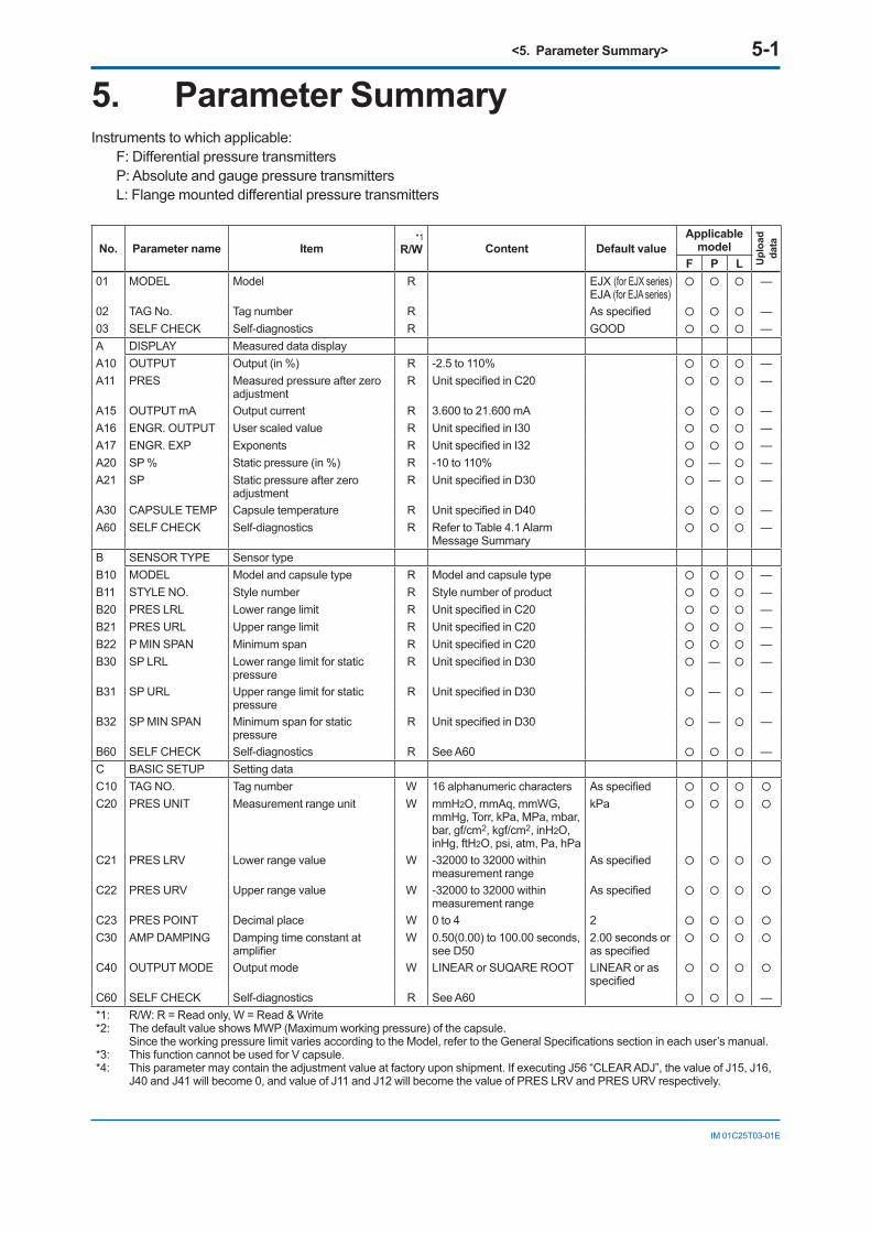
<5. Parameter Summary> 5-1
IM 01C25T03-01E
5. Parameter SummaryInstruments to which applicable:
F:DifferentialpressuretransmittersP: Absolute and gauge pressure transmittersL:Flangemounteddifferentialpressuretransmitters
No. Parameter name Item*1
R/W Content Default valueApplicable
model
Uplo
adda
ta
F P L01 MODEL Model R EJX (for EJX series)
EJA (for EJA series) —
02 TAG No. Tag number R Asspecified —03 SELF CHECK Self-diagnostics R GOOD —A DISPLAY Measured data displayA10 OUTPUT Output (in %) R -2.5 to 110% —A11 PRES Measured pressure after zero
adjustmentR UnitspecifiedinC20 —
A15 OUTPUT mA Output current R 3.600 to 21.600 mA —A16 ENGR. OUTPUT User scaled value R UnitspecifiedinI30 —A17 ENGR. EXP Exponents R UnitspecifiedinI32 —A20 SP % Static pressure (in %) R -10 to 110% — —A21 SP Static pressure after zero
adjustmentR UnitspecifiedinD30 — —
A30 CAPSULE TEMP Capsule temperature R UnitspecifiedinD40 —A60 SELF CHECK Self-diagnostics R Refer to Table 4.1 Alarm
Message Summary —
B SENSOR TYPE Sensor typeB10 MODEL Model and capsule type R Model and capsule type —B11 STYLE NO. Style number R Style number of product —B20 PRES LRL Lower range limit R UnitspecifiedinC20 —B21 PRES URL Upper range limit R UnitspecifiedinC20 —B22 P MIN SPAN Minimum span R UnitspecifiedinC20 —B30 SP LRL Lower range limit for static
pressureR UnitspecifiedinD30 — —
B31 SP URL Upper range limit for static pressure
R UnitspecifiedinD30 — —
B32 SP MIN SPAN Minimum span for static pressure
R UnitspecifiedinD30 — —
B60 SELF CHECK Self-diagnostics R See A60 —C BASIC SETUP Setting dataC10 TAG NO. Tag number W 16 alphanumeric characters Asspecified
C20 PRES UNIT Measurement range unit W mmH2O, mmAq, mmWG, mmHg, Torr, kPa, MPa, mbar, bar, gf/cm2, kgf/cm2, inH2O, inHg, ftH2O, psi, atm, Pa, hPa
kPa
C21 PRES LRV Lower range value W -32000 to 32000 within measurement range
Asspecified
C22 PRES URV Upper range value W -32000 to 32000 within measurement range
Asspecified
C23 PRES POINT Decimal place W 0 to 4 2
C30 AMP DAMPING Damping time constant at amplifier
W 0.50(0.00) to 100.00 seconds, see D50
2.00 seconds or asspecified
C40 OUTPUT MODE Output mode W LINEAR or SUQARE ROOT LINEAR or as specified
C60 SELF CHECK Self-diagnostics R See A60 —*1: R/W: R = Read only, W = Read & Write*2: The default value shows MWP (Maximum working pressure) of the capsule.
SincetheworkingpressurelimitvariesaccordingtotheModel,refertotheGeneralSpecificationssectionineachuser’smanual.*3: This function cannot be used for V capsule.*4: This parameter may contain the adjustment value at factory upon shipment. If executing J56 “CLEAR ADJ”, the value of J15, J16,
J40 and J41 will become 0, and value of J11 and J12 will become the value of PRES LRV and PRES URV respectively.
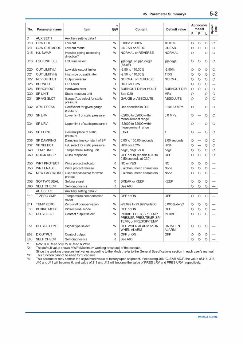
<5. Parameter Summary> 5-2
IM 01C25T03-01E
No. Parameter name Item*1
R/W Content Default valueApplicable
model
Uplo
adda
ta
F P LD AUX SET 1 Auxiliary setting data 1D10 LOW CUT Low cut W 0.00 to 20.00% 10.00%
D11 LOW CUT MODE Low cut mode W LINEAR or ZERO LINEAR
D15 H/L SWAP Impulse piping accessing direction*3
W NORMAL or REVERSE NORMAL —
D16 H2O UNIT SEL H2O unit select W @4degC or @20degC (68.0F)
@4degC
D20 OUT LIMIT (L) Low side output limiter W -2.50 to 110.00% -2.50%
D21 OUT LIMIT (H) High side output limiter W -2.50 to 110.00% 110%
D22 REV OUTPUT Output reversal W NORMAL or REVERSE NORMAL
D25 BURNOUT CPU error R HIGH or LOW —D26 ERROR OUT Hardware error W BURNOUT DIR or HOLD BURNOUT DIR
D30 SP UNIT Static pressure unit W See C20 MPa —
D31 SP A/G SLCT Gauge/Abs select for static pressure
W GAUGE or ABSOLUTE ABSOLUTE —
D32 ATM. PRESS Coefficientforgivengaugepressure
W UnitspecifiedinD30 0.10133 MPa —
D33 SP LRV Lower limit of static pressure W -32000 to 32000 within measurement range
0.0 MPa —
D34 SP URV Upper limit of static pressure*2 W -32000 to 32000 within measurement range
—
D35 SP POINT Decimal place of static pressure
W 0 to 4 1 —
D36 SP DAMPING Damping time constant of SP W 0.00 to 100.00 seconds 2.00 seconds —
D37 SP SELECT H/L select for static pressure W HIGH or LOW HIGH —
D40 TEMP UNIT Temperature setting unit W degC, degF, or K degC
D50 QUICK RESP Quick response W OFF or ON (enable 0.00 to 0.50 seconds at C30)
OFF
D55 WRT PROTECT Write protect indicator R NO or YES NO —D56 WRT ENABLE Write protect release W 8 alphanumeric characters None —D57 NEW PASSWORD User set password for write
protectW 8 alphanumeric characters None —
D58 SOFTWR SEAL Software seal R BREAK or KEEP KEEP —D60 SELF CHECK Self-diagnostics R See A60 —E AUX SET 2 Auxiliary setting data 2E10 T. ZERO CMP Temperature compensation
modeW OFF or ON OFF —
E11 TEMP ZERO Zero shift compensation W -99.999 to 99.999%/degC 0.000%/degC —E30 BI DIRE MODE Bidirectional mode W OFF or ON OFF —E50 DO SELECT Contact output select W INHIBIT, PRES, SP, TEMP,
PRES/SP, PRES/TEMP, SP/TEMP, or PRES/SP/TEMP
INHIBIT —
E51 DO SIG. TYPE Signal type select W OFF WHEN ALARM or ON WHEN ALARM
ON WHEN ALARM
—
E52 D OUTPUT Contact output R OFF or ON OFF —E60 SELF CHECK Self-diagnostics R See A60 —*1: R/W: R = Read only, W = Read & Write*2: The default value shows MWP (Maximum working pressure) of the capsule.
SincetheworkingpressurelimitvariesaccordingtotheModel,refertotheGeneralSpecificationssectionineachuser’smanual.*3: This function cannot be used for V capsule.*4: This parameter may contain the adjustment value at factory upon shipment. If executing J56 “CLEAR ADJ”, the value of J15, J16,
J40 and J41 will become 0, and value of J11 and J12 will become the value of PRES LRV and PRES URV respectively.

<5. Parameter Summary> 5-3
IM 01C25T03-01E
No. Parameter name Item*1
R/W Content Default valueApplicable
model
Uplo
adda
ta
F P LG ALARM SET Alarm settingG10 P AL MODE Alert mode W INHIBIT, HI. AL DETECT, LO.
AL DETECT, or HI/LO. AL DETECT
INHIBIT —
G11 P HI. AL VAL High side alert value W -32000 to 32000, unit specifiedinC20
100.000 kPa —
G12 P LO. AL VAL Low side alert value W -32000 to 32000, unit specifiedinC20
-100.000 kPa —
G20 SP AL MODE Static pressure alert mode W INHIBIT, HI. AL DETECT, LO. AL DETECT, or HI/LO. AL DETECT
INHIBIT — —
G21 SP HI. AL VAL High side alert value of SP*2 W -32000 to 32000, unit specifiedinD30
— —
G22 SP LO. AL VAL Low side alert value of SP W -32000 to 32000, unit specifiedinD30
0.00000 MPa — —
G30 T AL MODE Temperature alert mode W INHIBIT, HI. AL DETECT, LO. AL DETECT, or HI/LO. AL DETECT
INHIBIT —
G31 T HI. AL VAL High side alert value of temperature
W -50 to 130 120 degC —
G32 T LO. AL VAL Low side alert value of temperature
W -50 to 130 -40 degC —
G50 AUTO RECOVER Auto-recover from sensor error W OFF or ON ON —G60 SELF CHECK Self-diagnostics R See A60 —H AUTO SET Automatic setupH10 AUTO P LRV Lower range value auto setup W -32000 to 32000, unit
specifiedinC20Asspecified —
H11 AUTO P URV Upper range value auto setup W -32000 to 32000, unit specifiedinC20
Asspecified —
H20 AUTO SP LRV SP lower range value auto setup
W -32000 to 32000, unit specifiedinD30
0.00000 MPa — —
H21 AUTO SP URV SP upper range value auto setup*2
W -32000 to 32000, unit specifiedinD30
— —
H60 SELF CHECK Self-diagnostics R See A60 —I DISP SET Display settingI10 DISP OUT1 LCD output 1 W PRES, PRES %, ENGR.
PRES, SP, or SP %PRES %
I11 DISP OUT2 LCD output 2 W PRES, PRES %, ENGR. PRES, SP, SP %, or ---
---
I12 DISP OUT3 LCD output 3 W See I11 ---
I13 DISP OUT4 LCD output 4 W See I11 ---
I20 P DISP MODE % display mode W LINEAR or SQUARE ROOT LINEAR
I21 PRES % RESO % display resolution W NORMAL or HIGH RESOLUTION
NORMAL
I30 ENGR. UNIT User set engineering unit W 8 alphanumeric characters
I31 EASY EU SET Engineering unit select W —I32 ENGR. EXP Exponents W ---, ×10, ×100, ×1000 ---
I33 ENGR. LRV User set lower range limit W -32000 to 32000, unit specifiedinI30
0.00
I34 ENGR. URV User set upper range limit W -32000 to 32000, unit specifiedinI30
100.00
I35 ENGR. POINT Decimal place of user set W 0 to 4 1
I40 BAR INDICATR Bar indicator W OFF or ON ON
I41 POWER ON INF Display when powering on W OFF or ON ON —I60 SELF CHECK Self-diagnostics R See A60 —*1: R/W: R = Read only, W = Read & Write*2: The default value shows MWP (Maximum working pressure) of the capsule.
SincetheworkingpressurelimitvariesaccordingtotheModel,refertotheGeneralSpecificationssectionineachuser’smanual.*3: This function cannot be used for V capsule.*4: This parameter may contain the adjustment value at factory upon shipment. If executing J56 “CLEAR ADJ”, the value of J15, J16,
J40 and J41 will become 0, and value of J11 and J12 will become the value of PRES LRV and PRES URV respectively.

<5. Parameter Summary> 5-4
IM 01C25T03-01E
No. Parameter name Item*1
R/W Content Default valueApplicable
model
Uplo
adda
ta
F P LJ ADJUST Adjusting dataJ09 ADJ UNIT Pressure adjusting unit select W % or PRES UNIT PRES UNIT —J10 ADJ PRES Adjustment reference pressure R UnitspecifiedinJ09 —J11 P ZERO ADJ Automatic zero adjustment W -32000 to 32000, unit
specifiedinJ090.00000 kPa*4 —
J12 P SPAN ADJ Automatic span adjustment W -32000 to 32000, unit specifiedinJ09
100.000 kPa*4 —
J15 P ZERO DEV Manual zero adjustment W -32000 to 32000, unit specifiedinJ09
0 kPa*4 —
J16 P SPAN DEV Manual span adjustment W -32000 to 32000, unit specifiedinJ09
0 kPa*4 —
J20 ADJ SP Adjustment reference pressure of SP
R UnitspecifiedinJ09 — —
J21 SP ZERO ADJ Automatic SP zero adjustment W -32000 to 32000, unit specifiedinJ09
0.00000 MPa — —
J22 SP SPAN ADJ Automatic SP span adjustment*2
W -32000 to 32000, unit specifiedinJ09
— —
J25 SP ZERO DEV Manual SP zero adjustment W -32000 to 32000, unit specifiedinJ09
0.00000 MPa — —
J26 SP SPAN DEV Manual SP span adjustment W -32000 to 32000, unit specifiedinJ09
0.00000 MPa — —
J40 OUTPUT 4mA 4 mA adjustment W -10.000 to 10.000% 0.000%*4 —J41 OUTPUT 20mA 20 mA adjustment W -10.000 to 10.000% 0.000%*4 —J45 AMP TEMP Amplifiertemperature R UnitspecifiedD40 0 degC —J50 ADJ WHO Adjustment information W 8 alphanumeric characters —J51 ADJ DATE Adjustment information W 16 alphanumeric characters —J52 ADJ LOC Adjustment information W 8 alphanumeric characters —J53 ADJ DESC Adjustment information W 16 alphanumeric characters —J55 EXT ZERO ADJ External zeroing permission W INHIBIT or ENABLE ENABLE —J56 CLEAR ADJ Clear adjustment W ---, PRES, SP, 4-20mA, or
ALL--- —
J60 SELF CHECK Self-diagnostics R See A60 —K TEST Test parametersK10 OUTPUT X % Test output % setting W Within a range between D20
and D210.00% —
K40 DO TEST Test contact output W OFF or ON OFF —K45 TEST TIME “OUTPUT X %” and “DO
TEST” duration time selectionW 10 min, 30 min, 60 min,
3 hour, 6 hour, 12 hour10 min —
K50 TEST KEY1 Special maintenance parameter
W —
K51 TEST KEY2 Special maintenance parameter
W —
K52 TEST KEY3 Special maintenance parameter
W —
K53 TEST KEY4 Special maintenance parameter
W —
K60 SELF CHECK Self-diagnostics R See A60 —M DEVICE INFO Device informationM10 SERIAL NO. Serial number R —M11 MFTR. DATE Manufactured date R —M12 EXTRA NO. Customization number R —M15 SOFT REV Software revision R —M16 BRAIN REV BRAIN protocol revision R —M17 MEMO1 Memo W 16 alphanumeric characters —M18 MEMO2 Memo W 16 alphanumeric characters —M19 MEMO3 Memo W 16 alphanumeric characters —*1: R/W: R = Read only, W = Read & Write*2: The default value shows MWP (Maximum working pressure) of the capsule.
SincetheworkingpressurelimitvariesaccordingtotheModel,refertotheGeneralSpecificationssectionineachuser’smanual.*3: This function cannot be used for V capsule.*4: This parameter may contain the adjustment value at factory upon shipment. If executing J56 “CLEAR ADJ”, the value of J15, J16,
J40 and J41 will become 0, and value of J11 and J12 will become the value of PRES LRV and PRES URV respectively.

<5. Parameter Summary> 5-5
IM 01C25T03-01E
No. Parameter name Item*1
R/W Content Default valueApplicable
model
Uplo
adda
ta
F P LM20 ISOL MATL Capsule material W —M21 FILL FLUID Fillfluid W —M22 GASKET MATL Gasket material W —M23 PRO CON MATL Flange material W —M24 D-VENT MATL Vent plug material W —M25 PRO CON TYPE Process connection type W —M26 RS ISOL MATL Remote seal material W —M27 PRO CON SIZE Flange size W —M28 NUM RS Number of remote seal W —M29 RS FILL FLUID Fillfluidofremoteseal W —M30 RS TYPE Remote seal type W —M50 MS CODE 1 Modelandsuffixcode1 W —M51 MS CODE 2 Modelandsuffixcode2 W —M52 MS CODE 3 Modelandsuffixcode3 W —M53 MS CODE 4 Modelandsuffixcode4 W —M54 MS CODE 5 Modelandsuffixcode5 W —M55 MS CODE 6 Modelandsuffixcode6 W —M60 SELF CHECK Self-diagnostics R See A60 —P Record History of errorsP10 ERROR REC 1 Last error W See A60 GOOD —P12 ERROR REC 2 Second recent error W See A60 GOOD —P14 ERROR REC 3 Third recent error W See A60 GOOD —P16 ERROR REC 4 Forth recent error W See A60 GOOD —P60 SELF CHECK Self-diagnostics R See A60 —T CHARACTERIZR Signal characterizer settingT10 S. C. ENABLE Signal characterizer permission W INHIBIT or ENABLE INHIBIT —T11 NUM OF POINT Number of coordinates W 0 to 9 0 —T20 X START (FIX) Start point of X R 0.00% —T21 Y START (FIX) Start point of Y R 0.00% —T22 X1 Coordinate 1 of X W 0.00 to 100.00% 10.00 —T23 Y1 Coordinate 1 of Y W 0.00 to 100.00% 10.00 —T24 X2 Coordinate 2 of X W 0.00 to 100.00% 20.00 —T25 Y2 Coordinate 2 of Y W 0.00 to 100.00% 20.00 —T26 X3 Coordinate 3 of X W 0.00 to 100.00% 30.00 —T27 Y3 Coordinate 3 of Y W 0.00 to 100.00% 30.00 —T28 X4 Coordinate 4 of X W 0.00 to 100.00% 40.00 —T29 Y4 Coordinate 4 of Y W 0.00 to 100.00% 40.00 —T30 X5 Coordinate 5 of X W 0.00 to 100.00% 50.00 —T31 Y5 Coordinate 5 of Y W 0.00 to 100.00% 50.00 —T32 X6 Coordinate 6 of X W 0.00 to 100.00% 60.00 —T33 Y6 Coordinate 6 of Y W 0.00 to 100.00% 60.00 —T34 X7 Coordinate 7 of X W 0.00 to 100.00% 70.00 —T35 Y7 Coordinate 7 of Y W 0.00 to 100.00% 70.00 —T36 X8 Coordinate 8 of X W 0.00 to 100.00% 80.00 —T37 Y8 Coordinate 8 of Y W 0.00 to 100.00% 80.00 —T38 X9 Coordinate 9 of X W 0.00 to 100.00% 90.00 —T39 Y9 Coordinate 9 of Y W 0.00 to 100.00% 90.00 —T40 X END (FIX) End point of X R 100.00% —T41 Y END (FIX) End point of Y R 100.00% —T60 SELF CHECK Self-diagnostics R See A60 —*1: R/W: R = Read only, W = Read & Write*2: The default value shows MWP (Maximum working pressure) of the capsule.
SincetheworkingpressurelimitvariesaccordingtotheModel,refertotheGeneralSpecificationssectionineachuser’smanual.*3: This function cannot be used for V capsule.*4: This parameter may contain the adjustment value at factory upon shipment. If executing J56 “CLEAR ADJ”, the value of J15, J16,
J40 and J41 will become 0, and value of J11 and J12 will become the value of PRES LRV and PRES URV respectively.

<Appendix 1. Safety Instrumented Systems Installation> A1-1
IM 01C25T03-01E
Appendix 1. Safety Instrumented Systems Installation
When using the transmitters in a Safety Instrumented System application, refer to the Functional Safety Manual (Document No.: TI 01C25A05-01EN or TI 01C25A05-21EN for option code SLT) and follow the instructions and procedures described there.The document can be downloaded from the website of Yokogawa. (Website address: https://www.yokogawa.com/solutions/products-platforms/field-instruments/)In order to satisfy the requirement of Safety Instrumented System, executing parameters setting is required. Please refer to 3.2 “Setting Parameters Using the BT200” for setting range.
Pleasealsorefertothestatusoutputsettinginthesameclause.Afterinstallingthetransmitter,confirmthattherange and unit is set correctly. Calibration of the transmitters shall be done after completing the range setting.

Rev-1
IM 01C25T03-01E
Revision Information Title : DPharp BRAIN Communication Type Manual No. : IM 01C25T03-01E
Edition Date Page Revised Item1st Apr. 2004 — New publication.2nd Oct. 2004 3-19 3.2.3(20) •Addcapillaryfillfluiddensitycompensationsettingprocedure.3rd Aug. 2009 3-8 3.2.3(5) • Add example for hysteresis.
3-14 3.2.3(15) • Correct misprint.3-18 3.2.3(19) • Add CAUTION. Add note for hysteresis.
4th Jun. 2012 2-2 2.4 • Add integral indicator display when powering on3-5 3.2.2 • Add parameters in the menu tree (I41, K45)3-6 3.2.3(1) • Correct errors3-12 3.2.3(11)d • Change description for SOFTWARE SEAL3-15 3.2.3(15)a-2 •Correctthefigure3-17 3.2.3(16) • Correct the NOTE3-20 3.2.3(20) • Add EJA model name5-1 5 • Add EJA to default value of parameter No. "01"5-3 5 • Add parameter I415-4 5 • Add parameter K45
5th Jun. 2013 3-20 3.2.3(20) •Addconstantvalueoffillfluidforhighvacuumusediaphragmsealeddifferentialpressure/pressuretransmitters.
6th June 2014 2-1 2.1 • Change terminal drawing.2-1, 3-1 Add Note for BRAIN communication.
7th Apr. 2019 1-3 Delete “1.3 ATEX Documentation.”3-7 3.2.3 (1) • Add descriptions for Safety Instrumented System.3-20 3.2.3 (19) • Add descriptions for Safety Instrumented System.5-2 5. • Add *3.5-4 5. • Add *4.
A1-1 A1.2.3 • Add note.A1-2 A1.2.9 • Add document title and number.
8th Nov. 2019 1-1, A1-1 • Change the description for using the transmitters in Safety Instrumented Systems (SIS) application.