user’s manual - yokogawa electric im 01c20h01-01e 1. introduction 1. introduction thank you for...
TRANSCRIPT

User’sManual
Yokogawa Electric Corporation
Model EJ118W, EJ118N andEJ118Y Diaphragm SealedDifferential Pressure Transmitter[Style: S2]
IM 01C20H01-01E
IM 01C20H01-01E9th Edition

i
CONTENTS
IM 01C20H01-01EFD No. IM 01C20H01-01E9th Edition: June 2006(KP)All Rights Reserved, Copyright © 1993, Yokogawa Electric Corporation
CONTENTS
1. INTRODUCTION............................................................................................ 1-1
1.1 Safe Use of This Product .................................................................... 1-11.2 Warranty .............................................................................................. 1-2
2. HANDLING CAUTIONS ................................................................................ 2-1
2.1 Model and Specifications Check ......................................................... 2-12.2 Unpacking ........................................................................................... 2-12.3 Storage ................................................................................................ 2-12.4 Selecting the Installation Location ...................................................... 2-22.5 Pressure Connection ........................................................................... 2-22.6 Waterproofing of Cable Conduit Connections .................................... 2-22.7 Restrictions on Use of Radio Transceivers ........................................ 2-22.8 Insulation Resistance Test and Dielectric Strength Test .................... 2-32.9 Installation of Intrinsically Safe Type Transmitters ............................. 2-3
2.9.1 TIIS Intrinsically Safe Type .......................................................... 2-32.9.2 FM Intrinsically Safe Type ............................................................ 2-4
2.10 Installation of Flameproof Type Transmitters ..................................... 2-42.10.1 TIIS Flameproof Type .................................................................. 2-42.10.2 FM Explosionproof Type .............................................................. 2-5
2.11 EMC Conformity Standards ................................................................ 2-5
3. COMPONENT NAMES.................................................................................. 3-1
4. INSTALLATION ............................................................................................. 4-1
4.1 Precautions ......................................................................................... 4-14.2 Mounting the Diaphragm Seals .......................................................... 4-14.3 Transmitter Mounting .......................................................................... 4-24.4 Affixing the Teflon Film ....................................................................... 4-3
5. WIRING.......................................................................................................... 5-1
5.1 Wiring Precautions .............................................................................. 5-15.2 Selecting the Wiring Materials ............................................................ 5-15.3 Connections of External Wiring to Terminal Box ................................ 5-1
5.3.1 Power Supply Wiring Connection ................................................ 5-15.3.2 External Indicator Connection ...................................................... 5-15.3.3 BRAIN TERMINAL BT200 Connection ........................................ 5-25.3.4 Check Meter Connection.............................................................. 5-2
5.4 Wiring .................................................................................................. 5-25.4.1 Loop Configuration ....................................................................... 5-2
(1) General-use Type and Flameproof Type ..................................... 5-2(2) Intrinsically Safe Type ................................................................. 5-3
5.4.2 Wiring Installation ......................................................................... 5-3(1) General-use Type and TIIS Intrinsically Safe Type ...................... 5-3(2) TIIS Flameproof Type .................................................................. 5-3
5.5 Grounding ............................................................................................ 5-45.6 Power Supply Voltage and Load Resistance ..................................... 5-4
ii
CONTENTS
IM 01C20H01-01E
6. OPERATION.................................................................................................. 6-1
6.1 Liquid Level Measurement in a Closed Tank ..................................... 6-16.1.1 Preparation for Operation ............................................................. 6-16.1.2 Zero Adjustments ......................................................................... 6-26.1.3 Starting Operation ........................................................................ 6-36.1.4 Shutting Down Operation ............................................................. 6-3
6.2 Measurement Range for Liquid Level Measurement(Determination of Differential Pressure Range) .................................. 6-3
7. BRAIN TERMINAL BT200 OPERATION ..................................................... 7-1
7.1 BT200 Operation Precautions ............................................................. 7-17.1.1 Connecting the BT200 ................................................................. 7-17.1.2 Conditions of Communication Line .............................................. 7-1
7.2 BT200 Operating Procedures ............................................................. 7-27.2.1 Key Layout ................................................................................... 7-27.2.2 Operating Key Functions.............................................................. 7-2
(1) Alphanumeric Keys and SHIFT Keys .......................................... 7-2(2) Function Keys ............................................................................. 7-3
7.2.3 Calling Up Menu Addresses Using the Operating Keys.............. 7-47.3 Setting Parameters Using the BT200 ................................................. 7-5
7.3.1 Parameter Usage and Selection .................................................. 7-57.3.2 Setting Parameters ....................................................................... 7-6
(1) Tag No. Setup .............................................................................. 7-7(2) Calibration Range Setup ............................................................. 7-7(3) Damping Time Constant Setup ................................................... 7-8(4) Output Mode and Integral Indicator Display Mode Setup ........... 7-8(5) Output Signal Low Cut Mode Setup ............................................ 7-9(6) Integral Indicator Scale Setup ................................................... 7-10(7) Unit Setup for Displayed Temperature....................................... 7-11(8) Unit Setup for Displayed Static Pressure .................................. 7-11(9) Operation Mode Setup .............................................................. 7-11(10) Impulse Line Connection Orientation setup .............................. 7-11(11) Output Status Display/Setup when a CPU Failure .................... 7-12(12) Output Status Setup when a Hardware Error Occurs ............... 7-12(13) Bi-directional Flow Measurement Setup ................................... 7-12(14) Range Change while applying Actual Inputs ............................ 7-13(15) Zero Point Adjustment ............................................................... 7-13(16) Test Output Setup ..................................................................... 7-15(17) Ambient Temperature Zero Shift Compensation ....................... 7-15(18) User Memo Fields ..................................................................... 7-16
7.4 Displaying Data Using the BT200..................................................... 7-167.4.1 Displaying Measured Data ......................................................... 7-167.4.2 Display Transmitter Model and Specifications ........................... 7-17
7.5 Self-Diagnostics ................................................................................ 7-177.5.1 Checking for Problems ............................................................... 7-17
(1) Identifying Problems with BT200 .............................................. 7-17(2) Checking with Integral Indicator ................................................ 7-18
7.5.2 Errors and Countermeasures ..................................................... 7-19
8. MAINTENANCE............................................................................................. 8-1
8.1 Overview ............................................................................................. 8-18.2 Calibration Instrument Selection ......................................................... 8-18.3 Calibration ........................................................................................... 8-18.4 Disassembly and Reassembly ............................................................ 8-3

iii
CONTENTS
IM 01C20H01-01E
8.4.1 Replacing the Integral Indicator ................................................... 8-38.4.2 Replacing the CPU Board Assembly ........................................... 8-4
8.5 Troubleshooting ................................................................................... 8-58.5.1 Basic Troubleshooting .................................................................. 8-58.5.2 Troubleshooting Flow Charts ....................................................... 8-5
9. PARAMETER SUMMARY............................................................................. 9-1
10. GENERAL SPECIFICATIONS .................................................................... 10-1
10.1 Standard Specifications .................................................................... 10-110.2 Model and Suffix Codes .................................................................... 10-310.3 Optional Specifications ...................................................................... 10-510.4 Dimensions ........................................................................................ 10-6
INSTALLATION AND OPERATING PRECAUTIONS FOR TIIS INTRINSICALLYSAFE EQUIPMENT ............................................................................. EX-A03E
INSTALLATION AND OPERATING PRECAUTIONS FOR TIIS FLAMEPROOFEQUIPMENT........................................................................................ EX-B03E
Customer Maintenance Parts List
DPharp EJ Series Transmitter Section ...........................CMPL 01C20A01-01EModel EJ118W, EJ118N and EJ118Y Diaphragm Sealed
Differential Pressure Transmitter ......................... CMPL 01C20H01-01E
REVISION RECORD
IM 01C20H01-01E1-1
1. INTRODUCTION
1. INTRODUCTION
Thank you for purchasing the DPharp EJ differentialpressure transmitter.
Your DPharp Pressure Transmitter was preciselycalibrated at the factory before shipment. To ensureboth safety and efficiency, please read this manualcarefully before you operate the instrument.
Regarding This Manual• This manual should be provided to the end user.
• The contents of this manual are subject to changewithout prior notice.
• All rights reserved. No part of this manual may bereproduced in any form without Yokogawa’s writtenpermission.
• Yokogawa makes no warranty of any kind withregard to this manual, including, but not limited to,implied warranty of merchantability and fitness for aparticular purpose.
• If any question arises or errors are found, or if anyinformation is missing from this manual, pleaseinform the nearest Yokogawa sales office.
• The specifications covered by this manual arelimited to those for the standard type under thespecified model number break-down and do notcover custom-made instruments.
• Please note that changes in the specifications,construction, or component parts of the instrumentmay not immediately be reflected in this manual atthe time of change, provided that postponement ofrevisions will not cause difficulty to the user from afunctional or performance standpoint.
• Yokogawa assumes no responsibilities for thisproduct except as stated in the warranty.
• If the customer or any third party is harmed by theuse of this product, Yokogawa assumes no responsi-bility for any such harm owing to any defects in theproduct which were not predictable, or for anyindirect damages.
• The following safety symbols are used in thismanual:
WARNING
Indicates a potentially hazardous situation which,if not avoided, could result in death or seriousinjury.
CAUTION
Indicates a potentially hazardous situation which,if not avoided, may result in minor or moderateinjury. It may also be used to alert againstunsafe practices.
IMPORTANT
Indicates that operating the hardware or softwarein this manner may damage it or lead to systemfailure.
NOTE
Draws attention to information essential forunderstanding the operation and features.
1.1 Safe Use of This ProductFor the safety of the operator and to protect theinstrument and the system, please be sure to follow thismanual’s safety instructions when handling thisinstrument. If these instructions are not heeded, theprotection provided by this instrument may be im-paired. In this case, Yokogawa cannot guarantee thatthe instrument can be safely operated. Please payspecial attention to the following points:
(a) Installation• This instrument may only be installed by an engi-
neer or technician who has an expert knowledge ofthis device. Operators are not allowed to carry outinstallation unless they meet this condition.
IM 01C20H01-01E1-2
1. INTRODUCTION
• With high process temperatures, care must be takennot to burn yourself by touching the instrument orits casing.
• Never loosen the process connector nuts when theinstrument is installed in a process. This can lead toa sudden, explosive release of process fluids.
• When draining condensate from the pressuredetector section, take appropriate precautions toprevent the inhalation of harmful vapors and thecontact of toxic process fluids with the skin or eyes.
• When removing the instrument from a hazardousprocess, avoid contact with the fluid and the interiorof the meter.
• All installation shall comply with local installationrequirements and the local electrical code.
(b) Wiring• The instrument must be installed by an engineer or
technician who has an expert knowledge of thisinstrument. Operators are not permitted to carry outwiring unless they meet this condition.
• Before connecting the power cables, please confirmthat there is no current flowing through the cablesand that the power supply to the instrument isswitched off.
(c) Operation• Wait 5 min. after the power is turned off, before
opening the covers.
(d) Maintenance• Please carry out only the maintenance procedures
described in this manual. If you require furtherassistance, please contact the nearest Yokogawaoffice.
• Care should be taken to prevent the build up of dustor other materials on the display glass and the nameplate. To clean these surfaces, use a soft, dry cloth.
(e) Explosion Protected Type Instrument• Users of explosion proof instruments should refer
first to section 2.9 and 2.10 (Installation of anExplosion Protected Instrument) of this manual.
• The use of this instrument is restricted to those whohave received appropriate training in the device.
• Take care not to create sparks when accessing theinstrument or peripheral devices in a hazardouslocation.
(f) Modification• Yokogawa will not be liable for malfunctions or
damage resulting from any modification made to thisinstrument by the customer.
1.2 Warranty• The warranty shall cover the period noted on the
quotation presented to the purchaser at the time ofpurchase. Problems occurring during the warrantyperiod shall basically be repaired free of charge.
• If any problems are experienced with this instru-ment, the customer should contact the Yokogawarepresentative from which this instrument waspurchased or the nearest Yokogawa office.
• If a problem arises with this instrument, pleaseinform us of the nature of the problem and thecircumstances under which it developed, includingthe model specification and serial number. Anydiagrams, data and other information you caninclude in your communication will also be helpful.
• The party responsible for the cost of fixing theproblem shall be determined by Yokogawa follow-ing an investigation conducted by Yokogawa.
• The purchaser shall bear the responsibility for repaircosts, even during the warranty period, if themalfunction is due to:
- Improper and/or inadequate maintenance by thepurchaser.
- Malfunction or damage due to a failure to handle,use, or store the instrument in accordance with thedesign specifications.
- Use of the product in question in a location notconforming to the standards specified byYokogawa, or due to improper maintenance of theinstallation location.
- Failure or damage due to modification or repair byany party except Yokogawa or an approvedrepresentative of Yokogawa.
- Malfunction or damage from improper relocationof the product in question after delivery.
- Reason of force majeure such as fires, earthquakes,storms/floods, thunder/lightening, or other naturaldisasters, or disturbances, riots, warfare, orradioactive contamination.

IM 01C20H01-01E2-1
2. HANDLING CAUTIONS
2. HANDLING CAUTIONS
The EJ118W, EJ118N and EJ118Y DifferentialPressure Transmitters are thoroughly tested at thefactory before shipment. When the transmitters aredelivered, visually check them to make sure that nodamage occurred during shipment. Also check that alltransmitter mounting hardware shown in Figure 2.1was received. If the instrument was ordered without themounting bracket, the transmitter mounting hardwarewill not be included. After checking the transmitter,repack it in its original packaging in the way it wasdelivered, then keep it like this until installation.
This chapter describes important cautions regardinghow to handle the transmitter. Read carefully beforeusing the transmitter. As for the cautions other thandescribed in this chapter, please read the cautions inthe relative chapters. If you have any problems orquestions, contact your nearest Yokogawa servicestation or sales representative.
Mounting bracket
U-bolt
U-bolt nuts
Transmitter mounting bolts
F0201E.EPS
Figure 2.1 Transmitter Mounting Hardware
2.1 Model and SpecificationsCheck
The model name and specifications are indicated on thename plate attached to the case.
This information should be included in all correspon-dence.
If the reverse operating mode was ordered (reversesignal), ‘REVERSE’ will be inscribed in field *1; ifsquare root display mode was ordered, ‘SQRT’ isinscribed in field *2; if square root output mode wasordered, ‘SQRT’ is inscribed in field *3.
F0202E.EPS
Figure 2.2 Name Plate Example of TIIS Flameproof Type
2.2 UnpackingWhen moving the transmitter to the installation site,keep it in its original packaging. Then, unpack thetransmitter there to avoid damage on the way.
2.3 StorageThe following precautions must be observed whenstoring the instrument, especially for a long period.
(1) Select a storage area which meets the followingconditions:• It is not exposed to rain or water,• It suffers minimum vibration and shock,• It has an ambient temperature and relative
humidity within the following ranges:Ambient temperature:
–40 to 85°C for a transmitter without integralindicator–30 to 80°C for a transmitter with integralindicator
Relative humidity:5% to 100% R.H. (at 40°C)

IM 01C20H01-01E2-2
2. HANDLING CAUTIONS
However, it is preferable at normal temperature andhumidity (approx. 25°C and 65% R.H.).
(2) When storing the transmitter, repack it as nearly aspossible to the way it was packed when deliveredfrom the factory.
(3) If storing a transmitter that has been used, thor-oughly clean diaphragm surfaces (the pressure-detector sections) of the diaphragm seals, so that nomeasured fluid remains on them.In addition, make sure before storing that thepressure-detector and transmitter assemblies aresecurely mounted.
2.4 Selecting the InstallationLocation
The transmitter is designed to withstand severeenvironmental conditions. However, to ensure stableand accurate operation for many years, the followingprecautions must be observed when selecting aninstallation location.
(1) Ambient TemperatureAvoid locations subject to wide temperature variationsor a significant temperature gradient. If the location isexposed to radiant heat from plant equipment, provideadequate thermal insulation and/or ventilation.
(2) Ambient AtmosphereAvoid installing the transmitter in a corrosive atmo-sphere. If the transmitter must be installed in a corro-sive atmosphere, there must be adequate ventilation aswell as measures to prevent intrusion or stagnation ofrain water in conduits.
(3) Shock and VibrationSelect an installation site suffering minimum shock andvibration (although the transmitter is designed to berelatively resistant to shock and vibration).
(4) Installation of Explosion-protected Trans-mitters
Explosion-protected transmitters can be installed inhazardous areas according to the types of gases forwhich they are certified. Important precautions regard-ing such use are included at the end of this manualunder “Installation and Operating Precautions forIntrinsically Safe Explosion-Protected Instruments” and“Installation and Operating Precautions for FlameproofExplosion-Protected Instruments.” Read these thor-oughly and carefully.
2.5 Pressure Connection
WARNING
(1) Instrument installed in the process is underpressure. Never loosen or tighten the flangebolts as it may cause dangerous spouting ofprocess fluid.
(2) If the accumulated process fluid may be toxicor otherwise harmful, take appropriate careto avoid contact with the body, or inhalationof vapors even after dismounting the instru-ment from process line for maintenance.
The following precautions must be observed in order tosafely operate the transmitter under pressure.
• Never apply a pressure higher than the specifiedmaximum working pressure.
2.6 Waterproofing of CableConduit Connections
Apply a non-hardening sealant to the threads towaterproof the transmitter cable conduit connections.(See Figure 5.4.2a, 5.4.2b, 5.4.2c and 5.4.2d.)
2.7 Restrictions on Use of RadioTransceivers
IMPORTANT
Although the transmitter has been designed toresist high frequency electrical noise, if a radiotransceiver is used near the transmitter or itsexternal wiring, the transmitter may be affectedby high frequency noise pickup. To test for sucheffects, bring the transceiver in use slowly from adistance of several meters from the transmitter,and observe the measurement loop for noiseeffects. Thereafter, always use the transceiveroutside the area affected by noise.

IM 01C20H01-01E2-3
2. HANDLING CAUTIONS
2.8 Insulation Resistance Testand Dielectric Strength Test
Since the transmitter has undergone insulation resis-tance and dielectric strength tests at the factory beforeshipment, normally these tests are not required.However, if required, observe the following precau-tions in the test procedures.
(1) Do not perform such tests more frequently than isabsolutely necessary. Even test voltages that do notcause visible damage to the insulation may degradethe insulation and reduce safety margins.
(2) Never apply a voltage exceeding 500V DC (100VDC with an internal lightning protector) for theinsulation resistance test, nor a voltage exceeding500V AC (100V AC with an internal lightningprotector) for the dielectric strength test.
(3) Before conducting these tests, disconnect all signallines from the transmitter terminals. Perform thetests in the following procedure:
• Insulation Resistance Test(1) Short-circuit the + and – SUPPLY/BT terminals in
the terminal box.(2) Turn OFF the insulation tester. Then connect the
insulation tester plus (+) lead wire to the shortedSUPPLY/BT terminals and the minus (–) leadwireto the grounding terminal.
(3) Turn ON the insulation tester power and measurethe insulation resistance. The voltage should beapplied short as possible to verify that the insula-tion resistance is at least 20 MΩ.
(4) After completing the test and being very careful notto touch exposed conductors disconnect theinsulation tester and connect a 100 kΩ resistorbetween the grounding terminal and the short-circuiting SUPPLY/BT terminals. Leave thisresistor connected at least one second to dischargeany static potential. Do not touch the terminalswhile it is discharging.
• Dielectric Strength Test(1) Short-circuit the + and – SUPPLY/BT terminals in
the terminal box.(2) Turn OFF the dielectric strength tester. Then
connect the tester between the shorted SUPPLY/BTterminals and the grounding terminal. Be sure toconnect the grounding lead of the dielectric strengthtester to the ground terminal.
(3) Set the current limit on the dielectric strength testerto 10 mA, then turn ON the power and graduallyincrease the test voltage from ‘0’ to the specifiedvoltage.
(4) When the specified voltage is reached, hold it forone minute.
(5) After completing this test, slowly decrease thevoltage to avoid any voltage surges.
2.9 Installation of IntrinsicallySafe Type Transmitters
WARNING
To pressure the safety of explosionproof equip-ment requires great care during mounting,wiring, and piping. Safety requirements alsoplace restrictions on maintenance and repairactivities. Please read the following sections verycarefully.
2.9.1 TIIS Intrinsically Safe Type
The TIIS intrinsically safe type differential pressuretransmitter is designed for hazardous areas whereexplosive or inflammable gases or vapors may bepresent as specified in the Recommended Practice forExplosion-Protected Electrical Installations in GeneralIndustries (1979), established by the Research Instituteof Industrial Safety, Ministry of Labor (Japan). (Thesetransmitters can be installed in Division 0, 1 and 2areas.)
To preserve the safety of intrinsically safe typeequipment requires great care during mounting, wiring,and piping and conduit installation.
The safety requirements also place restrictions onmaintenance and repair activities. Users absolutelymust read the “Installation and Operating Precautionsfor Intrinsically Safe Explosion-Protected Instruments”at the end of this manual.
Confirming the certification markA certification mark with the certification number isapplied on the instrument’s body.There is a fixed correspondence between certificationnumber and the safety barrier to be used as shownbelow. Please cross out the unnecessary certificationmark depending on a barrier.
For connecting with BARD-800 safety barrier;Certification No.: 56212 (without lightning
protector)56213 (with lightning protector)
For connecting with BARD-400 safety barrier;Certification No.: 54512
Please also cross out the unnecessary rating data on thedata plate accordingly.

IM 01C20H01-01E2-4
2. HANDLING CAUTIONS
If there is no label with the number corresponding tothe barrier to be used, you cannot use that barrier.Please use the correct barrier corresponding to thecertification number on the instrument.
2.9.2 FM Intrinsically Safe Type
Caution for FM Intrinsically safe type.
Note 1. Hazardous locations*Intrinsically Safe for Class I, Division 1,
Groups A, B, C & D.Class II, Division 1, Groups E, F & G and ClassIII, Division 1 Hazardous Locations.
*Outdoor hazardous locations, NEMA 4.*Temperature Class : T4*Ambient temperature : –20 to 60°C
Note 2. Entity Parameters*Vmax = 31.5V DC, Imax = 93 mA, Pmax = 1.1 W,
Ci = 2 nF, Li = 1.04 mH*Entity Installation Requirements
Vmax ≥ Voc or Vt, Imax ≥ Isc or It,Ca ≥ Ci + Ccable, La ≥ Li + Lcable
Note 3. Installation*Barrier must be installed in an enclosure that
meets the requirements of ANSI/ISA S82.01.*Resistance between lnt. Safe Gnd and earth
ground must be less than 1 ohm.*Control equipment connected to barrier must not
use or generate more than 250 Vrms or Vdc.*Installation should be in accordance with ANSI/
ISA RP12.6 “Installation of Intrinsically SafeSystems for Hazardous (Classified) Locations”and the National Electric Code (ANSI/NFPA 70).
*The configuration of associated apparatus must beFMRC Approved.
*Dust-tight conduit seal must be used wheninstalled in a Class II, III, Group E, F and Genvironments.
*No revision to drawing without prior FMRCApproved.
*Associated apparatus manufacturer’s installationdrawing must be followed when installing thisapparatus.
*The maximum power delivered from the barriermust not exceed 1.1 W.
F0203E.EPS
Class I, II, III, Division 1,Groups A, B, C, D, E, F, G
Transmitters Safety Barrier
Supply
Hazardous Location Nonhazardous Location
General PurposeEquipment
+
–
+
–
+
–
+
–
2.10 Installation of FlameproofType Transmitters
WARNING
To pressure the safety of explosionproof equip-ment requires great care during mounting,wiring, and piping. Safety requirements alsoplace restrictions on maintenance and repairactivities. Please read the following sections verycarefully.
2.10.1 TIIS Flameproof Type
The TIIS flameproof type differential pressure trans-mitter is designed for hazardous areas where inflam-mable gases or vapors may be present as specified inthe Recommended Practice for Explosion-ProtectedElectrical Installations in General Industries (1985),established by the Research Institute of IndustrialSafety, Ministry of Labor (Japan). (These transmitterscan be installed in Division 1 and 2 areas.)
To preserve the safety of flameproof type equipmentrequires great care during mounting, wiring, and pipingand conduit installation.
The safety requirements also place restrictions onmaintenance and repair activities. Users absolutelymust read “Installation and Operating Precautions forFlameproof Explosion-Protected Instruments” at theend of this manual.
CAUTION (For instruments without integral indicator)
When the fill fluid near the sensor part movesfrom within, the instrument outputs a failuresignal either high or low of the specific signal. Inthat case, generate the alarm to identify that thefailure signal is output since the event mayinvalidate the flameproof approval.If the optional integral indicator is equipped, theindicator identifies the alarm on its display.Therefore, no other alarm generation is neces-sary.
Transmitter
Hazardous Location Nonhazardous Location
PowerSupply
DCSDisplay
4 to 20 mA DC 1 to 5V DC
F0205E.EPS
Figure 2.3 Example of Using DCS (Distributed ControlSystem)

IM 01C20H01-01E2-5
2. HANDLING CAUTIONS
2.10.2 FM Explosionproof Type
Caution for FM Explosionproof type
Note 1. Hazardous locations:*Applicable standard: FM3600, FM3615, FM3810,
NEMA 250, ANSI/NFPA 70.*Explosionproof for Class I, Division 1, Groups B,
C and D.*Dust-ignitionproof for Class II, Division 1, Groups
E, F and G.*Suitable for Class III, Division 1.*Outdoor hazardous locations, NEMA 4.
Note 2. Wiring*All wiring shall comply with National Electrical
Code ANSI/NEPA70 and Local Electrical Codes.*In hazardous location, wiring to be in conduit as
shown in the figure.Note 3. Operation
*WARNING:DO NOT OPEN COVER WHILE CIRCUIT ISALIVE.
*Take care not to generate mechanical spark whenaccess to the instrument and peripheral devices inhazardous location.
Note 4. Maintenance and Repair*The instrument modification or parts replacement
by other than authorized representative ofYokogawa Electric Corporation is prohibited andwill void Factory Mutual Explosionproof Certifi-cation.
Nonhazardous Location Equipment
42V DC Max. 4 to 20 mA DC Signal
Nonhazardous Locations
Hazardous Locations
18'' (457 mm) Max.
Sealing FittingConduit
EJ Series
F0206E.EPS
2.11 EMC Conformity StandardsAS/NZS CISPR11

IM 01C20H01-01E3-1
3. COMPONENT NAMES
3. COMPONENT NAMES
Figure 3.1 Component Names (Model EJ118W External View)
*For details, refer to Figure 3.1.2
F0301E.EPS
Cover flange
Diaphragm seal(high pressure side)
Diaphragm seal(low pressure side)
Allen screw (for securing cover flange)
Capillary
Pressure-detector section
Transmitter section*

IM 01C20H01-01E3-2
3. COMPONENT NAMES
Integral indicator
CPU board assembly
Terminal box cover
Terminal box
Case cover
Mounting screw
Setting pin (CN6) (Optional)
Zero-adjustment screw
Note : Integral indicator is optional
Transmitter section
Setting pin(CN6) position (Note 1)
Burn-out direction
Output at burn-out
H
L
H
L
HIGH
LOW
110% or higher (21.6mA DC)
–5% or lower(3.2mA DC)
Note 1 : • Insert the pin (CN6) as shown in the above figure into the H or L side (set to the L side for delivery).
• The setting can be confirmed by calling up parameter D52 using the BRAIN TERMINAL. Refer to Subsection. 7. 3. 2(11).
Display Symbol
E.ZERO
Meaning of Display Symbol
Output mode is “square root”. (Display is not lit when “proportional” mode.)
The output signal being zero-adjusted is increasing.
The output signal being zero-adjusted is decreasing.
Display mode is “square root”. (Display is not lit when “proportional” mode.)
The zero-adjustment screw is “enabled”. (Display is not lit when the screw is “disabled.”)
F0302E.EPS
Figure 3.1.2 Component Names (Tranmitter Section Details)

IM 01C20H01-01E4-1
4. INSTALLATION
4. INSTALLATION
4.1 PrecautionsBefore installing the transmitter, read the cautionarynotes in Section 2.4, “Selecting the InstallationLocation.” For additional information on the ambientconditions allowed at the installation location, see the“Standard Specifications” later in this manual.
IMPORTANT
• When welding piping during construction, takecare not to allow welding currents to flowthrough the transmitter.
• Do not step on this instrument after installation.
4.2 Mounting the DiaphragmSeals
Mount the diaphragm seals using the flanges as shownin Figure 4.1. Figure 4.2 shows how to mount thediaphragm seals on a tank. The customer shouldprepare the mating flange, gasket, bolts and nuts.
Nuts
Flange
Diaphragm
ød
Gasket
Bolts
The product is shipped with these parts assembled.
Correctly install the diaphragm seals on the high and low pressure sides of the process, checking the label on each seal.
F0401E.EPS
Figure 4.1 Mounting the Diaphragm Seals
IMPORTANT
Please use a gasket which has a bigger insidediameter than that of gasket facing (d) ondiaphragm seal. In case a gsket which has asmaller inside diameter than that of gasketfacing is used, it may cause an error as thegasket prevents diaphragm from workingcorrectly. (Refer to ‘Dimensions’ later in thismanual)
IMPORTANT
• When measuring the liquid level of the tank, theminimum liquid level (zero point) must be set toa level at least 50 mm above the center of thehigh pressure side diaphragm seal (see Figure4.2).
• Correctly install the diaphragm seals on thehigh and low pressure sides of the process,checking the label on each seal.
• To avoid measuring error duets temperaturedifference between the two diaphragm seals,capillaries must be bound together. The capil-laries must be securely fixed to the tank wall toprevent movement by wind or vibration. If thecapillaries are too long, loosely coil the excessand secure using suitable clamps.
• During the diaphragm seal installation, ensureas far as possible that no seal liquid head isapplied to the diaphragm seals.
• Excercise care so as not to damage diaphragmsurface. Since the diaphragm protrudes ap-proximately 1 mm from the flange surface,placing the diaphragm seals with their dia-phragm surfaces facing downward may dam-age the diaphragm surfaces.
• Do not sharply bend or twist capillaries or applyexcessive stress to them.
IM 01C20H01-01E4-2
4. INSTALLATION
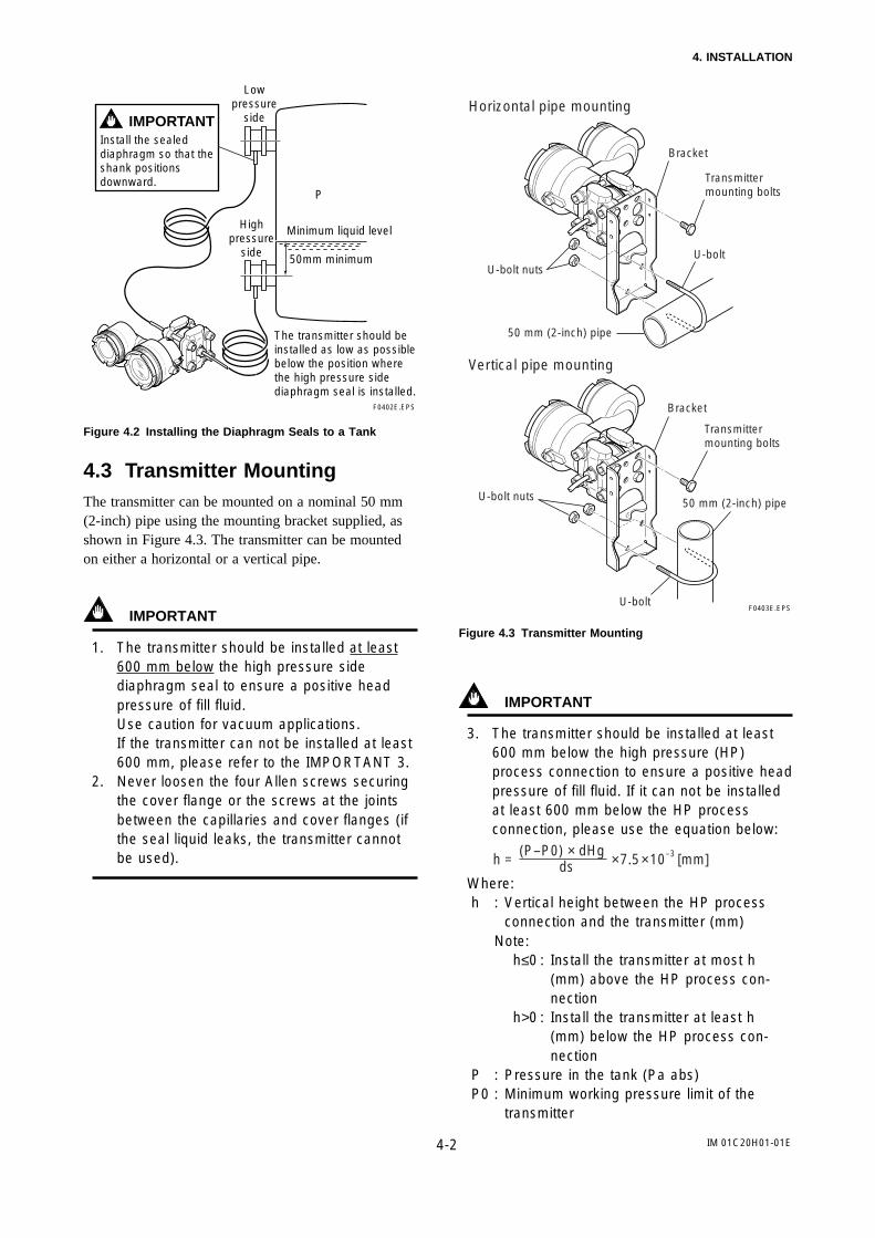
The transmitter should be installed as low as possible below the position where the high pressure side diaphragm seal is installed.
IMPORTANTInstall the sealed diaphragm so that the shank positions downward.
F0402E.EPS
P
Low pressure
side
High pressure
side50mm minimum
Minimum liquid level
Figure 4.2 Installing the Diaphragm Seals to a Tank
4.3 Transmitter MountingThe transmitter can be mounted on a nominal 50 mm(2-inch) pipe using the mounting bracket supplied, asshown in Figure 4.3. The transmitter can be mountedon either a horizontal or a vertical pipe.
IMPORTANT
1. The transmitter should be installed at least600 mm below the high pressure sidediaphragm seal to ensure a positive headpressure of fill fluid.Use caution for vacuum applications.If the transmitter can not be installed at least600 mm, please refer to the IMPORTANT 3.
2. Never loosen the four Allen screws securingthe cover flange or the screws at the jointsbetween the capillaries and cover flanges (ifthe seal liquid leaks, the transmitter cannotbe used).
F0403E.EPS
Horizontal pipe mounting
Vertical pipe mounting
U-bolt
U-bolt nuts50 mm (2-inch) pipe
U-bolt
Transmitter mounting bolts
U-bolt nuts
Bracket
Bracket
50 mm (2-inch) pipe
Transmitter mounting bolts
Figure 4.3 Transmitter Mounting
IMPORTANT
3. The transmitter should be installed at least600 mm below the high pressure (HP)process connection to ensure a positive headpressure of fill fluid. If it can not be installedat least 600 mm below the HP processconnection, please use the equation below:
h = × 7.5 × 10 [mm](P–P0) × dHg
ds–3
Where:h : Vertical height between the HP process
connection and the transmitter (mm)Note:
h≤0 : Install the transmitter at most h(mm) above the HP process con-nection
h>0 : Install the transmitter at least h(mm) below the HP process con-nection
P : Pressure in the tank (Pa abs)P0 : Minimum working pressure limit of the
transmitter

IM 01C20H01-01E4-3
4. INSTALLATION
Note : To determine minimum workingpressure refer to one of the following:1) If the ambient temperature range
is -10 to 50°C.3229 (The model code of thematerial of the wetted part is S)3690 (The model code of thematerial of the wetted part is T)6419 (The model code of thematerial of the wetted part is H)4918 (The model code of thematerial of the wetted part is U)
2) 5733 (If the ambient temperaturerange is 50 to 60°C)
ds : Specific gravity of fill fluid (at 25°C), referto GS 1C20H1-E.
dHg : Specific gravity of the Mercury 13.6 (at25°C)
F0404E.EPS
Ph
0
(+)
(–)
ds: Specific gravity of the seal liquid
Low pressure
side
High pressure
side
Figure 4.4 Example of Installation to Tank (Caution onInstallation)
4.4 Affixing the Teflon FilmThe FEP Teflon option includes a Teflon film andfluorinated oil.
Before mounting the diaphragm seal to the processflange, affix the Teflon film as follows:
IMPORTANT
(1) Position the diaphragm seal so that thediaphragm is in a upward position.
(2) Pour the fluorinated oil on the diaphragm andgasket area covering it completely andevenly. Be careful not to scratch the dia-phragm or change its shape.
(3) Affix the Teflon film over the diaphragm andgasket area.
(4) Next, carefully inspect the cover and try toidentify any entrapped air between thediaphragm and the Teflon film. The air mustbe removed to ensure accuracy. If airpockets are present, use your fingers toremove the air by starting at the center of thediaphragm and work your way out.
(5) Place the gasket with the teflon film and affixto the process flange.
Diaphraqm sealF0405E.EPS
Diaphragm
Fluorinated oil[PART No. : F9145YN]
Gasket area
Teflon film[PART No. : F9149CY for 3 inch (80mm) flange]
Figure 4.5 Affixing the Teflon Film

IM 01C20H01-01E5-1
5. WIRING
5. WIRING
5.1 Wiring Precautions
IMPORTANT
1.Lay wiring as far as possible from electricalnoise sources such as large capacity trans-formers, motors, and power supplies.
2.Remove electrical connection dust cap beforewiring.
3.All threaded parts must be treated with water-proofing sealant. (A non-hardening siliconegroup sealant is recommended.)
4.To prevent noise pickup, do not pass signaland power cables through the same ducts.
5.Explosion-protected instruments must be wiredin accordance with specific requirements (and,in certain countries, legal regulations) in orderto preserve the effectiveness of their explo-sion-protected features.
Refer to the “Installation and OperatingPrecautions for TIIS Flameproof Equipment”and “Installation and Operating Precautionsfor TIIS Intrinsically Safe Equipment” at theend of this manual for correct wiring.
5.2 Selecting the Wiring Materi-als
1. Use stranded leadwires or cables which are the sameas or better than 600V grade PVC insulated wire(JIS C3307) or equivalent for wiring.
2. Use shielded wires in areas that are susceptible toelectrical noise.
3. In areas with higher or lower ambient temperatures,use wires or cables appropriate for such tempera-tures.
CAUTION
If the transmitter is flameproof and the ambienttemperature is 50°C or more, use cables havinga maximum allowable heat resistance of least75°C in consideration of the instrument’s genera-tion of heat or the cables’ self-heating.
4. In environments where oils, solvents, corrosive gasesor liquids may be present, use wires or cables thatare resistant to such substances.
5. It is recommended that crimp-on solderless terminallugs (for 4 mm screws) with insulating sleeves beused for leadwire ends.
5.3 Connections of ExternalWiring to Terminal Box
5.3.1 Power Supply Wiring Connection
Connect the power supply wiring to the SUPPLY/BT +and – terminals.
Power supply–
+F0501E.EPS
Terminal box
Figure 5.3.1 Power Supply Wiring Connection
5.3.2 External Indicator Connection
Connect wiring for external indicators to the METER +and – terminals.
(Note) Use a external indicator whose internalresistance is 10 Ω or less.
– +
F0502E.EPS
Terminal box
External indicator Jumper
(Remove jumper)
Power supply
–
+
Figure 5.3.2 External Indicator Connection

IM 01C20H01-01E5-2
5. WIRING
5.3.3 BRAIN TERMINAL BT200 Connec-tion
Connect the BT200 to the SUPPLY/BT + and –terminals (Use hooks).
BT200
Jumper (should be attached if the external indicator is not connected)
F0503E.EPS
–
+
Terminal box
Power supply
Since the BT200 is AC-coupled to the terminal box, polarity does not matter.
Figure 5.3.3 BT200 Connection
5.3.4 Check Meter Connection
Connect the check meter to the CHECK + and –terminals (use hooks).
• A 10 to 50 mV DC signal is output corresponding to4 to 20 mA DC output signal from the CHECK +and – terminals.
F0504E.EPS
Check meter –
+
Terminal boxPower supply
Figure 5.3.4 Check Meter Connection
5.4 Wiring
CAUTION
For the intrinsically safe equipment and flame-proof equipment, wiring materials and wiringwork for these equipment including peripheralsare strictly restricted.Users absolutely must read “Installation andOperating Precautions for TIIS Intrinsically SafeEquipment” and “Installation and OperatingPrecautions for TIIS Flameproof Equipment” atthe end of this manual prior to the work.
5.4.1 Loop Configuration
Since the DPharp uses a two-wire transmission system,signal wiring is also used as power wiring.
DC power is required for the transmitter loop. Thetransmitter and distributor are connected as shownbelow.
For details of the power supply voltage and loadresistance, see Section 5.6; for communications linerequirements, see Subsection 7.1.2.
(1) General-use Type and Flameproof Type
F0505E.EPS
Distributor (Power supply unit)
Receiver instrument
Transmitter terminal box
Figure 5.4.1a Connection between Transmitter andDistributor

IM 01C20H01-01E5-3
5. WIRING
(2) Intrinsically Safe TypeFor intrinsically safe type, a safety barrier must beincluded in the loop.
F0506E.EPS
Distributor (Power supply unit)
Receiver instrument
Safety barrier
Transmitter terminal box
Figure 5.4.1b Connection between Transmitter andDistributor
5.4.2 Wiring Installation
NOTE
For installation of intrinsically safe type andflameproof type, see section 2.9 and 2.10.
(1) General-use Type and TIIS IntrinsicallySafe Type
Make cable wiring using metallic conduit or water-proof glands (marine watertight cable glands forelectric appliances, JIS F8801).
• Apply a non-hardening sealant to the terminal boxconnection port and to the threads on the flexiblemetal conduit for waterproofing.
F0507E.EPS
Flexible metal conduit
Wiring metal conduit
Tee
Drain plug
Apply a non-hardening sealant to the threads for waterproofing.
Figure 5.4.2a Typical Wiring Using Flexible Metal Conduit
(2) TIIS Flameproof TypeWire cables through a flameproof packing adapter, orusing a flameproof metal conduit.
Wiring cable through flameproof packing adapterfor only TIIS flameproof type(see Figure 5.4.2b)• Use only flameproof packing adapters approved
by Yokogawa.• Apply a non-hardening sealant to the terminal box
connection port and to the threads on the flame-proof packing adapter for waterproofing.
Flameproof packing adapter
Flexible metal conduitWiring metal conduit
Tee
Drain plug
Apply a non-hardening sealant to the threads for waterproofing.
F0508E.EPS
Figure 5.4.2b Typical Cable Wiring Using FlameproofPacking Adapter
• Measure the cable outer diameter in two directionsto within 1mm.
• Calculate the average of the two diameters, and usepacking with an internal diameter nearest to thisvalue (see Table 5.4.2).
Table 5.4.2 Flameproof Packings and Applicable CableOuter Diameters
Optional Code
Wiring Port Thread Diameter
Applicable Cable OD (mm)
Identifying Mark
Part Number
T0501E.EPS
G9601AM8 to 10
10.1 to1216 8-1016 10-12
22 10-1222 12-1422 14-16
G 1/2(PF 1/2)
G11
G12
G9601AN10 to12
12.1 to1414.1 to16
G 3/4(PF 3/4)
G21
G22
• Mounting flameproof packing adapter body toconduit connection (see Figure 6.4.2c)
1. Screw the flameproof packing adapter into theterminal box until the O-ring touches the wiring port(at least 6 full turns), and firmly tighten the lock nutwith a wrench.
2. Insert the cable through the union cover, the unioncoupling, the clamp nut, the clamp ring, the gland,the washer, the rubber packing, and the packing box,in that order.
3. Insert the end of the cable into the terminal box.

IM 01C20H01-01E5-4
5. WIRING
4. Tighten the union cover to grip the cable. Whentightening the union cover, tighten approximatelyone turn past the point where the cable will nolonger move up and down.Proper tightening is important. If it is too tight, acircuit break in the cable may occur; if not tightenough, the flameproof effectiveness will becompromised.
5. Fasten the cable by tightening the clamp nut.6. Tighten the lock nut on the union cover.7. Connect the cable wires to each terminal.
F0509.EPS
Apply a non-hardning sealant to the threads of these fittings for waterproofing.
Lock nut
Packing
Washer
Gland
Clamp ring
Clamp nut
Union coupling
Lock nut
Adapter body
O-ring
Packing box
Union cover
Cable
Figure 5.4.2c Installing Flameproof Packing Adapter
Flameproof metal conduit wiring• A seal fitting must be installed near the terminal
box connection port for a sealed construction.• Apply a non-hardening sealant to the threads of
the terminal box connection port, flexible metalconduit and seal fitting for waterproofing.
F0510E.EPS
Non-hazardous area
Hazardous area
Flameproof heavy-gauge steel conduit
Tee
Drain plug
Seal fitting
Gas sealing device
Apply a non-hardening sealant to the threads of these fittings for waterproofing.
Flameproof flexible metal conduit
(After wiring, impregnate the fitting with a compound to seal tubing.)
Figure 5.4.2d Typical Wiring Using Flameproof MetalConduit
5.5 Grounding1. Grounding should satisfy Class D requirements
(grounding resistance, 100 Ω or less). Grounding isrequired for TIIS flameproof type and intrinsicallysafe type.
(Note) In case of with Built-in Lightning Protector,grounding should satisfy Class C require-ments (grounding resistance, 10 Ω or less).
2. There are ground terminals on the inside and outsideof the terminal box. Either of these terminals may beused.
3. Use 600 V grade PVC insulated wires for grounding.
Ground terminal
Terminal box
F0511E.EPS
Figure 5.5 Ground Terminals
5.6 Power Supply Voltage andLoad Resistance
When configuring the loop, make sure that the externalload resistance is within the range in the figure below.
600
250
0 12 17.9
R = 42.3 (E12) (General-use type and flameproof type)
R = 42.3 (E16.5) (Intrinsically safe type)
26.216.5 22.4 31.5
42
Power supply voltage E (V DC)F0512E.EPS
Operating region
Ext
erna
l loa
d re
sist
ance
R (
Ω)
Figure 5.6 Relationship between Power Supply Voltageand External Load Resistance
IM 01C20H01-01E6-1
6. OPERATION
6. OPERATION
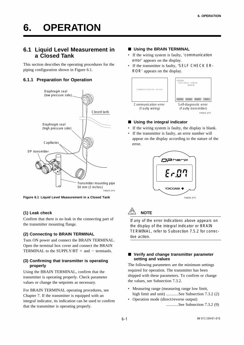
6.1 Liquid Level Measurement ina Closed Tank
This section describes the operating procedures for thepiping configuration shown in Figure 6.1.
6.1.1 Preparation for Operation
Closed tank
F0601E.EPS
Transmitter mounting pipe 50 mm (2 inches)
Capillaries
Diaphragm seal (high pressure side)
Diaphragm seal (low pressure side)
DP transmitter
Figure 6.1 Liquid Level Measurement in a Closed Tank
(1) Leak checkConfirm that there is no leak in the connecting part ofthe transmitter mounting flange.
(2) Connecting to BRAIN TERMINALTurn ON power and connect the BRAIN TERMINAL.Open the terminal box cover and connect the BRAINTERMINAL to the SUPPLY/BT and termianls.
(3) Confirming that transmitter is operatingproperly
Using the BRAIN TERMINAL, confirm that thetransmitter is operating properly. Check parametervalues or change the setpoints as necessary.
For BRAIN TERMINAL operating procedures, seeChapter 7. If the transmitter is equipped with anintegral indicator, its indication can be used to confirmthat the transmitter is operating properly.
Using the BRAIN TERMINAL• If the wiring system is faulty, ‘communication
error’ appears on the display.• If the transmitter is faulty, ‘SELF CHECK ER-
ROR’ appears on the display.
communication error
PARAM C60:SELF CHECK ERROR
DATA DIAG PRNT ESC
Communication error (Faulty wiring)
Self-diagnostic error (Faulty transmitter)
F0602E.EPS
Using the integral indicator• If the wiring system is faulty, the display is blank.• If the transmitter is faulty, an error number will
appear on the display according to the nature of theerror.
F0603E.EPS
NOTE
If any of the error indications above appears onthe display of the integral indicator or BRAINTERMINAL, refer to Subsection 7.5.2 for correc-tive action.
Verify and change transmitter parametersetting and values
The following parameters are the minimum settingsrequired for operation. The transmitter has beenshipped with these parameters. To confirm or changethe values, see Subsection 7.3.2.
• Measuring range (measuring range low limit,high limit and unit) ............See Subsection 7.3.2 (2)
• Operation mode (direct/reverse output) ............See Subsection 7.3.2 (9)

IM 01C20H01-01E6-2
6. OPERATION
6.1.2 Zero Adjustments
IMPORTANT
Do not turn off the power to the transmitterimmediately after a zero adjustment. Poweringoff within 30 seconds after a zero adjustment willreturn the adjustment back to the previoussettings.
Zero adjustment of the transmitter can be set in twoways: uing the zero-adjustment screw of the transmit-ter, and through the operation of the BRAIN TERMI-NAL.
For output signal checking, display the parameter‘A10: OUTPUT(%)’ in the BRAIN TERMINAL.
Output signal (%) display
PARAM A10:OUTPUT(%) 0.0 % A11:ENGR OUTPUT
A20:AMP TEMP
DATA DIAG PRNT ESC
F0604E.EPS
After operating preparation is completed, adjust thezero point.
When adjusting the transmitter zero point, the liquidlevel in a tank does not have to be set to the low limit(0%) of the measuring range. In such case, match thetransmitter output signal with the actual measuredvalue using, for example, a glass gauge.
(1) When the liquid level in a tank can be setto the low limit of the measuring range(0%):
Using the transmitter zero-adjustmentscrew
Before using the zero-adjustment screw outside thetransmitter case, confirm the following.
• Parameter ‘J20: EXT ZERO ADJ’ display must be‘ENABLE’. See Subsection 7.3.2 (14) for the settingprocedure.
• If the transmitter is equipped with an integralindicator, ‘E.ZERO’ must be displayed.
Use a slotted screwdriver to turn the zero-adjustmentscrew. Turn the screw clockwise to increase the outputor counterclockwise to decrease the output, the zeropoint adjustment can be adjusted with a resolution of0.01% of the setting range.
The degree of zero adjustments varies with the screwturning speed. Therefore, turn the screw slowly for fineadjustment and quickly for coarse adjustment.
Zero-adjustment screw
F0605E.EPS
Using the BRAIN TERMINALZero point can be adjusted by simple key operation ofthe BRAIN TERMINAL.
Select parameter ‘J10: ZERO ADJ’, and press theENTER key twice. The zero point will be adjustedautomatically to the output signal 0% (4 mA DC).Confirm that the setting value displayed for theparameter is ‘0.0%’ before pressing the ENTER key.See Subsection 7.3.2 (14) for BRAIN TERMINALoperating procedures.
SET J10:ZERO ADJ –0.0 % + 000.0
CLR ESCF0606E.EPS
Display when parameter J10 is selected.
Press key twice for 0% output 4 mA DC.
IM 01C20H01-01E6-3
6. OPERATION
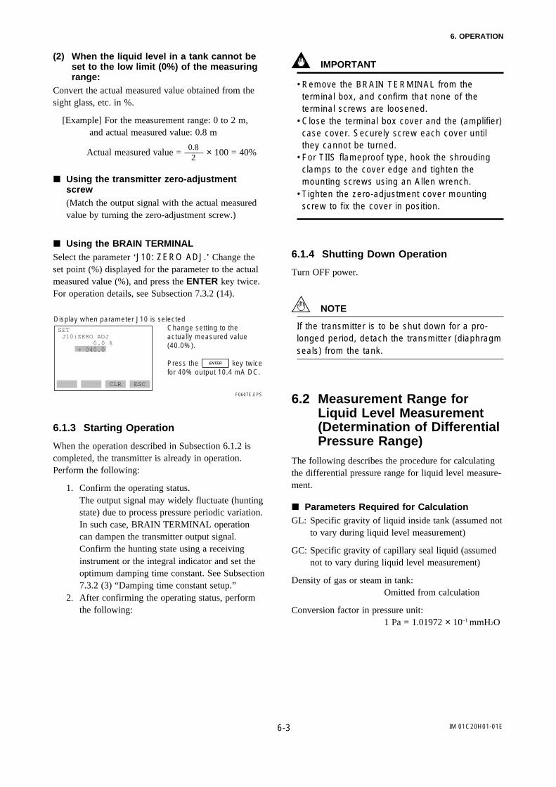
(2) When the liquid level in a tank cannot beset to the low limit (0%) of the measuringrange:
Convert the actual measured value obtained from thesight glass, etc. in %.
[Example] For the measurement range: 0 to 2 m, and actual measured value: 0.8 m
Actual measured value = 0.82
× 100 = 40%
Using the transmitter zero-adjustmentscrew(Match the output signal with the actual measuredvalue by turning the zero-adjustment screw.)
Using the BRAIN TERMINALSelect the parameter ‘J10: ZERO ADJ.’ Change theset point (%) displayed for the parameter to the actualmeasured value (%), and press the ENTER key twice.For operation details, see Subsection 7.3.2 (14).
SET J10:ZERO ADJ 0.0 % + 040.0
CLR ESC
F0607E.EPS
Display when parameter J10 is selectedChange setting to the actually measured value (40.0%).
Press the key twice for 40% output 10.4 mA DC.
6.1.3 Starting Operation
When the operation described in Subsection 6.1.2 iscompleted, the transmitter is already in operation.Perform the following:
1. Confirm the operating status.The output signal may widely fluctuate (huntingstate) due to process pressure periodic variation.In such case, BRAIN TERMINAL operationcan dampen the transmitter output signal.Confirm the hunting state using a receivinginstrument or the integral indicator and set theoptimum damping time constant. See Subsection7.3.2 (3) “Damping time constant setup.”
2. After confirming the operating status, performthe following:
IMPORTANT
• Remove the BRAIN TERMINAL from theterminal box, and confirm that none of theterminal screws are loosened.
• Close the terminal box cover and the (amplifier)case cover. Securely screw each cover untilthey cannot be turned.
• For TIIS flameproof type, hook the shroudingclamps to the cover edge and tighten themounting screws using an Allen wrench.
• Tighten the zero-adjustment cover mountingscrew to fix the cover in position.
6.1.4 Shutting Down Operation
Turn OFF power.
NOTE
If the transmitter is to be shut down for a pro-longed period, detach the transmitter (diaphragmseals) from the tank.
6.2 Measurement Range forLiquid Level Measurement(Determination of DifferentialPressure Range)
The following describes the procedure for calculatingthe differential pressure range for liquid level measure-ment.
Parameters Required for CalculationGL: Specific gravity of liquid inside tank (assumed not
to vary during liquid level measurement)
GC: Specific gravity of capillary seal liquid (assumednot to vary during liquid level measurement)
Density of gas or steam in tank:Omitted from calculation
Conversion factor in pressure unit:1 Pa = 1.01972 × 10⁻¹ mmH2O
IM 01C20H01-01E6-4
6. OPERATION
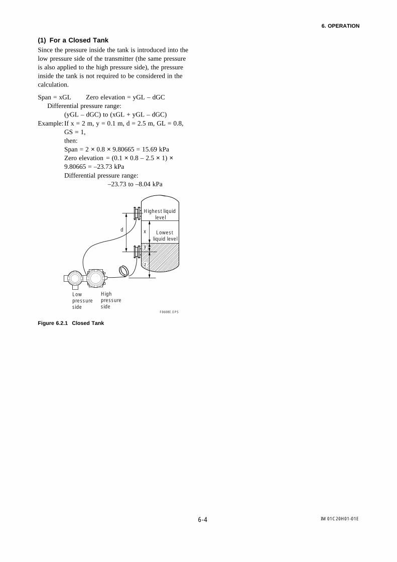
(1) For a Closed TankSince the pressure inside the tank is introduced into thelow pressure side of the transmitter (the same pressureis also applied to the high pressure side), the pressureinside the tank is not required to be considered in thecalculation.
Span = xGL Zero elevation = yGL – dGCDifferential pressure range:
(yGL – dGC) to (xGL + yGL – dGC)Example: If x = 2 m, y = 0.1 m, d = 2.5 m, GL = 0.8,
GS = 1,then:Span = 2 × 0.8 × 9.80665 = 15.69 kPaZero elevation = (0.1 × 0.8 – 2.5 × 1) ×9.80665 = –23.73 kPaDifferential pressure range:
–23.73 to –8.04 kPa
F0608E.EPS
Highest liquid level
Lowest liquid level
y
x
z
d
Low pressure side
High pressure side
Figure 6.2.1 Closed Tank

7-1
7. BRAIN TERMINAL BT200 OPERATION
IM 01C20H01-01E
7. BRAIN TERMINAL BT200OPERATION
The DPharp is equipped with BRAIN communicationscapabilities, so that range changes, Tag No. setup,monitoring of self-diagnostic results, and zero pointadjustment can be handled by remote control viacommunications from a BT200 BRAIN TERMINALor CENTUM CS console. This section describesprocedures for settings and changing parameters usingthe BT200. For details concerning the BT200, see IM01C00A11-01E, “BT200 User Manual.”
7.1 BT200 Operation Precautions
7.1.1 Connecting the BT200
The transmitter and the BT200 can be connected eitherby connecting the BT200 to the BT200 connectionhooks provided in the transmitter terminal box, or byconnecting it to a relaying terminal board.
DPharp
BT200
BT200
BT200BT200
Relaying terminals
Distributor
Control room
Terminal board
F0701E.EPS
Figure 7.1.1 Connecting the BT200
7.1.2 Conditions of Communication Line
DPharp
BT200
Cable resistance Rc
Cable resistance Rc
Load resistance R
ccPower supply
Loop resistance = R+2Rc = 250 to 600Ω Loop capacitance = 0.22µF max.
F0702E.EPS
Figure 7.1.2 Conditions of Communication Line
7-2
7. BRAIN TERMINAL BT200 OPERATION
IM 01C20H01-01E
7.2 BT200 Operating Procedures
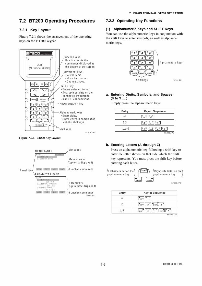
7.2.1 Key Layout
Figure 7.2.1 shows the arrangement of the operatingkeys on the BT200 keypad.
F0703E.EPS
Alphanumeric keys•Enter digits.•Enter letters in combination with the shift keys.
LCD(21 character × 8 lines)
Movement keys •Select items. •Move the cursor. •Change pages.
Power ON/OFF key
Function keys Use to execute the commands displayed at the bottom of the screen.
ENTER key •Enters selected items. •Sets up input data on the connected instrument.•Runs BT200 functions.
Shift keys
Figure 7.2.1 BT200 Key Layout
PARAM A10:OUTPUT 100.0 % A11:ENGR. OUTPUT 100 kPa A20:AMP TEMP 23 deg C
MENU A:DISPLAY B:SENSOR TYPE
BATTERY
HOME SET ADJ ESC
DATA DI AG PRNT
F0704E.EPS
Menu choices(up to six displayed)
MessagesMENU PANEL
Panel title Function commands
PARAMETER PANEL
Parameters (up to three displayed)
Function commands
7.2.2 Operating Key Functions
(1) Alphanumeric Keys and SHIFT KeysYou can use the alphanumeric keys in conjunction withthe shift keys to enter symbols, as well as alphanu-meric keys.
Shift keys
Alphanumeric keys
F0705E.EPS
a. Entering Digits, Symbols, and Spaces(0 to 9 ... )Simply press the alphanumeric keys.
Entry Key-in Sequence
–4
0.3
F0706E.EPS
1 –9
b. Entering Letters (A through Z)Press an alphanumeric key following a shift key toenter the letter shown on that side which the shiftkey represents. You must press the shift key beforeentering each letter.
Left-side letter on the alphanumeric key
F0707E.EPS
Right-side letter on the alphanumeric key
Entry Key-in Sequence
W
IC
J. BF0708E.EPS

7-3
7. BRAIN TERMINAL BT200 OPERATION
IM 01C20H01-01E
Use the function key [F2] CAPS to select betweenuppercase and lowercase (for letters only). The casetoggles between uppercase and lowercase each timeyou press [F2] CAPS.
CODE CAPS CLR ESC CODE caps CLR ESC
Entry
Boy
Key-Sequence
Entering uppercase Entering lowercase
( B ) ( y )( o )
(Lower case)
F0709E.EPS
Use the function key [F1] CODE to enter symbols.
The following symbols will appear in sequence, one ata time, at the coursor each time you press [F1] CODE:
/ . – , + * ) ( ‘ & % $ # ” !
To enter characters next to these symbols, press [>]to move the cursor first.
Entry
l/m
Key-in Sequence
T0710E.EPS
( / ) ( m )( I )
(Lower case)
(2) Function KeysThe functions of the function keys depend on thefunction commands on display.
MENU A:DISPLAY B:SENSOR TYPE
HOME SET ADJ ESC Function commands
Function keysF0711E.EPS
Function Command List
ADJ
CAPS / caps
CODE
CLR
DATA
DEL
DIAG
ESC
HOME
NO
OK
PARM
SET
SLOT
UTIL
*COPY
*FEED
*LIST
*PON / POFF
*PRNT
*GO
*STOP
Displays the ADJ menu
Selects the case between uppercase and lowercase
Selects symbols
Erases input data or deletes all data
Updates parameter data
Deletes one character
Calls the self-check panel
Returns to the most recent display
Displays the menu panel
Quits setup and returns to the previous display
Proceeds to the next panel
Enters the parameter number setup mode
Displays the SET menu
Returns to the slot selection panel
Calls the utility panel
Prints out parameters on display
Paper feed
Lists all parameters in the menu
Turns the setup change data printout mode on or off
Changes to the print mode
Starts printing
Cancels printing
Parameters marked * are indicated only by the BT200-P00 (equipped with printer).
Command Function
T0701E.EPS
7-4
7. BRAIN TERMINAL BT200 OPERATION
IM 01C20H01-01E
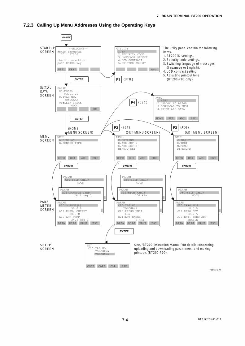
7.2.3 Calling Up Menu Addresses Using the Operating Keys
DATA DIAG PRNT ESC
PARAM A60:SELF CHECK GOOD
CODE CAPS CLR ESC
––WELCOME––BRAIN TERMINAL ID: BT200
check connection push ENTER key
UTIL FEED esc
PARAM 01:MODEL EJxxx-xx 02:TAG NO. YOKOGAWA 03:SELF CHECK GOOD
OK
HOME SET ADJ ESC
FUNC 1.MENU 2.UPLOAD TO BT200 3.DOWNLOAD TO INST 4.PRINT ALL DATA
HOME SET ADJ ESC
MENU A.DISPLAY B.SENSOR TYPE
HOME SET ADJ ESC
MENU C.SETTING D.AUX SET 1 E.AUX SET 2 H:AUTO SET
HOME SET ADJ ESC
MENU J.ADJUST K.TEST M.MEMO P:RECORD
DATA DIAG PRNT ESC
DATA DIAG PRNT ESCDATA DIAG PRNT ESC DATA DIAG PRNT ESC
PARAM C60:SELF CHECK GOOD
PARAM C22:HIGH RANGE 100 kPa
DATA DIAG PRNT ESC
PARAM J60:SELF CHECK GOOD
PARAM J10:ZERO ADJ 0.0 % J11:ZERO DEV 22.2 % J20:EXT. ZERO ADJ ENABLE
SET C10:TAG NO. YOKOGAWA YOKOGAWA
DATA DIAG PRNT ESC
PARAM A10:OUTPUT(%) 50.0 % A11:ENGR, OUTPUT 20.0 M A20:AMP TEMP 24.5 deg C
DATA DIAG PRNT ESC
PARAM C10:TAG NO. YOKOGAWA C20:PRESS UNIT kPa C21:LOW RANGE 0 kPa
PARAM A21:CAPSULE TEMP 26.5 deg C
UTILITY 1.ID 2.SECURITY CODE 3.LANGUAGE SELECT 4.LCD CONTRAST 5.PRINTER ADJUST
(HOME MENU SCREEN) (SET MENU SCREEN) (ADJ MENU SCREEN)
(UTIL)
(SET)
(ESC)
(ADJ)
The utility panel contain the following items.1. BT200 ID settings.2. Security code settings.3. Switching language of messages (Japanese or English).4. LCD contrast setting.5. Adjusting printout tone (BT200-P00 only).
F0712E.EPS
STARTUPSCREEN
INITIALDATASCREEN
MENUSCREEN
PARA-METERSCREEN
SETUPSCREEN
See, “BT200 Instruction Manual” for details concerninguploading and downloading parameters, and makingprintouts (BT200-P00).

7-5
7. BRAIN TERMINAL BT200 OPERATION
IM 01C20H01-01E
7.3 Setting Parameters Using theBT200
IMPORTANT
Do not turn off the transmitter as soon as BRAINTERMINAL settings have been made. If thetransmitter is turned off less than 30 secondsafter parameters have been set, the set data willnot be stored and the terminal returns to previ-ous settings.
Table 7.3.1 Parameter Usage and Selection
7.3.1 Parameter Usage and Selection
Before describing the procedure for setting parameters,we present the following table showing how theparameters are used in what case.
Setup Item Description
Sets the integral indicator scale to a % scale or user-set engineering units scale.For engineering units scale, 4 data are set: user-set engineering scale designation unit (for BT200 display), display value at 4 mA DC, and display value at 20 mA DC.
Used mainly to stabilize output near 0% if output signal is the square root mode.Two modes are available: forcing output to 0% for input below a specific value, or changing to proportional output for input below a specific value.
Reverses the direction for 4 to 20 mA DC output relative to input.Reverse mode is used for applications in which safety requires that output be driven toward 20 mA if input is lost.
Sets a unit for static pressure displayed on the BT200.
Sets a unit for temperatures displayed on the BT200.
Sets modes for output signal and integral indicator to “Linear mode” (proportional to input differential pressure) or to “Square root mode” (proportional to flow).
Adjusts the output response speed for 4 to 20 mA DC.Can be set in 9 increments from 0.2 to 64 s.
Sets the Tag No. (using 16 alphanumeric characters).Note: Up to 8 alphanumerics (upper case
letters) can be used in the BT100.
Sets the calibration range for 4 to 20 mA DC.Sets three data items : range unit, input value at 4 mA DC (LRV), and input value at 20 mA DC (HRV).Note: LRV and HRV can be specified with
range value specifications up to 5 digits (excluding any decimal point) within the range of –32000 to 32000.
Integral indicator scale range and unit setupP.7-10
Output signal low cut mode setupP.7-9
Operation mode (normal/ reverse signal) setupP.7-11
Unit setup for displayed static pressure P.7-11
Unit setup for displayed temperatureP.8-11
Damping time constant setup P.7-8
Tag No. setupP.7-7
Calibration range setupP.7-7
Output and integral indicator display mode setupP.7-8
Setup Item Description
Used to measure bi-directional flows.Output at zero flow is 12 mA DC, with output range equally divided between forward and reverse flow.Can be used with square root mode.
Allows user to enter up to 5 items of any desired text in up to 8 uppercase alphanumeric characters per item.
Adjusts zero point.This can be done either using the external zero-adjustment screw on the transmitter or using the BT200.
Range for 4 to 20 mA DC signal is set with actual input applied.Sets 20 mA DC output precisely with respect to user’s reference instrument output.Note that DPharp is calibrated with high accuracy before shipment, so span should be set using the normal range setup.
Used where installation conditions make it imperative to connect high pressure side impulse line to low pressure side of transmitter. Reversal of orientation should be dealt with by reversing impulse line wherever possible. Use this function only where there is no alternative.
Displays the status of 4 to 20 mA DC output when a CPU failure. The parameter of the standard unit is fixed to the high limit value (a change to the low limit value is not possible).Specify the optional code /C1 when selection of a HIGH/LOW limit is necessary.
Bi-directional flow measurementP.7-12
Sets the status of the 4 to 20 mA DC output when an abnormal status is detected with the capsule or the amplifier as the result of self-diagnosis. One of the following statuses; last held, high limit, and low limit values, can be selected.
Output status setup when a hardware error occursP.7-12
User memo fieldsP.7-16
Used for loop checks.Output can be set freely from –2.5% to 110% in 1% steps.
Test output (fixed current output) setupP.7-15
Zero point adjustmentP.7-13 to 7-14
Range change (while applying actual inputs)P.7-13
Impulse line connection orientation (higher pressure on right/left side) setup P.7-11
Output status display/setup when a CPU failureP.7-12
T0702E.EPS
Allows user to compensate the zero shift by ambient temperature effect on capillary tubes.
Ambienttemperature zero shift compensationP.7-15

7-6
7. BRAIN TERMINAL BT200 OPERATION
IM 01C20H01-01E
7.3.2 Setting Parameters
Table 7.3.2 shows a summary of parameters and theirdefault values (set values on delivery). Set or changethe parameters as necessary. After completing these, donot fail to use the “DIAG” key to confirm that“GOOD” is displayed for the self-diagnostic result“ 60: SELF CHECK”.
Table 7.3.2 Parameter Summary
No. Description Default ValueData Setting RangeItem
C10
C20
C21
C22
C30
C40
D10
D11
D20
D21
D22
D23
D30
D31
D40
D45
D52
D53
E10
E14
E15
E30
H10
H11
TAG NO.
PRESS UNIT
LOW RANGE
HIGH RANGE
AMP DAMPING
OUTPUT MODE
LOW CUT
LOW CUT MODE
DISP SELECT
DISP UNIT
DISP LRV
DISP HRV
TEMP UNIT
STAT. P. UNIT
REV OUTPUT
H/L SWAP
BURN OUT
ERROR OUT
DFS MODE
TEMP SELECT
TEMP ZERO
BI DIRE MODE
AUTO LRV
AUTO HRV
Tag number
Differential pressure units
Lower range value (LRV)
Higher range value (HRV)
Damping time constant
Output mode
Low cut value
Low cut mode
Display selection
Engineering unit to be displayed
Display LRV
Display HRV
Temperature unit
Static pressure unit
Operation mode
Impulse line connection orientation
The output when a CPU failure
The output when a hardware error occurs
DFS mode
Reference temperature sensor
Zero shift compensation setup
Normal / reverse mode
Automatic LRV setup
Automatic HRV setup
As specified when ordered.
As specified when ordered.
As specified when ordered.
As specified when ordered.
2 s
As specified when ordered.If not specified, OUT : LIN DSP : LIN.
10.0%
LINEAR
NORMAL (%)
As specified when ordered.
As specified when ordered.
deg C
As specified when ordered.If not specified, kPa or MPa.
As specified when ordered.If not specified, NORMAL.
NORMAL
HIGH
HIGH
ON
CAP.TEMP
0.00
OFF
Displays the same data as C21.
Displays the same data as C22.
16 alphanumeric characters
Selected from mmH2O, mmAq, mmWG, mmHg, Torr, Pa, hPa, kPa, MPa, mbar, bar, gf/cm2, kgf/cm2,in H2O, inHg, ftH2O, psi, or atm.
–32000 to 32000But within measurement range
–32000 to 32000But within measurement range
Selected from 0.2, 0.5, 1.0, 2.0, 4.0, 8.0, 16.0, 32.0, or 64.0 s.
OUT : LIN DSP : LINOUT : LIN DSP : SQROUT : SQR DSP : SQR
0.0 to 20.0%
LINEAR, ZERO
NORMAL (%), USER SET
–19999 to 19999
–19999 to 19999
deg C, deg F
Selected from mmH2O, mmAq, mmWG, mmHg, Torr, Pa, hPa, kPa, MPa, mbar, bar, gf/cm2, kgf/cm2, in H2O, inHg, ftH2O, psi, or atm.
NORMAL, REVERSE
NORMAL, REVERSE
HIGH (Note)
HOLD, HIGH, LOW
OFF, ON
AMP.TEMP/CAP.TEMP
±10.00
OFFON
–32000 to 32000
–32000 to 32000
T0703E.EPS
Note: Specify the optional code /C1 when selection of a HIGH/LOW limit is necessary.

7-7
7. BRAIN TERMINAL BT200 OPERATION
IM 01C20H01-01E
(1) Tag No. Setup (C10: TAG NO)The Tag No. is set as specified in the order before theinstrument is shipped. Use the procedure below tochange the Tag No.
Up to 16 alphanumeric characters can be entered forthe Tag No.
• Example: Set a Tag No. to FIC-1a.
PARAM 01:MODEL EJ118W-DM 02:TAG NO. YOKOGAWA 03:SELF CHECK GOOD
OK
MENU A:DISPLAY B:SENSOR TYPE
HOME SET ADJ ESC
MENU C:SETTING D:AUX SET 1 E:AUX SET 2 H:AUTO SET
HOME SET ADJ ESC
MENU C10:TAG NO. YOKOGAWA C20:PRESS UNIT kPa C21:LOW RANGE 0 kPaDATA DIAG PRNT ESC
<When power is off>
––WELCOME––BRAIN TERMINAL ID: BT200
check connection push ENTER key
UTIL FEED
SET C10:TAG NO. YOKOGAWA YOKOGAWA
CODE CAPS CLR ESC
(caps)
FOKOGAWA
FIKOGAWA
FICOGAWA
FIC-GAWA
FIC-1AWA
FIC-1aWA
FIC-1a
Press the key to turn on
the BT200.
Connect DPharp and BT200 using a communication cable
and press the key.
Select C: SETTING and press
the key.
Select C10: TAG NO. and
press the key.
Displays the name of connected DPharp model, TAG NO. and diagnostics
information. Press the (OK)
key after confirmation.
Press the (SET) key to
display the SET menu panel.
Set the new TAG NO. (FIC-1A).
When you have made an entry mistake,
return the cursor using the key,
then reenter.F0713E.EPS
Display Description
SET C10:TAG NO. FIC-1a
FEED NO OK
DATA DIAG PRNT ESC
SET C10:TAG NO. YOKOGAWA FIC-1a
PRINTER OFF F2:PRINTER ON
PARAM C10:TAG NO. FIC-1a C20:PRESS UNIT kPa C21:LOW RANGE 0 kPa
FEED POFF NO
F0714E.EPS
SET C10:TAG NO. YOKOGAWA FIC-1a _
CODE caps CLE ESC
This is the panel for confirming set data. The set data itemsflash. When all items have been confirmed, press the
again. (To go back
to the setting panel, press the
(NO) key).
The DPharp TAG NO. was overwritten.
Press the (OK) key to
return to the parameter panel.
Press the (NO) key to
return to the setting panel.
Set TAG NO. and press the
key.
(2) Calibration Range Setup a. Setting Calibration Range Unit
(C20: PRESS UNIT)The unit is set at the factory before shipment ifspecified at the time of order.Follow the procedure at the below to change theunit.
mmH2OmmAqmmWGmmHgTorrkPaMPambarbargf/cm2
kgf/cm2
inH2OinHgftH2OpsiatmPahPa
ESC
SET C20:PRESS UNIT kPa
FEED NO OK
SET C20:PRESS UNIT kPa < kPa > < MPa > < mbar > < bar >
•Example: Change the unit from “kPa” to “MPa”.
Use the or
key to select “MPa”.
Press the key twice
to enter the setting.
Press the (OK) key.
F0715E.EPS
7-8
7. BRAIN TERMINAL BT200 OPERATION
IM 01C20H01-01E
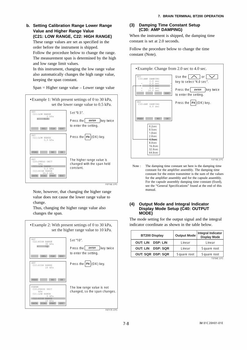
b. Setting Calibration Range Lower RangeValue and Higher Range Value(C21: LOW RANGE, C22: HIGH RANGE)These range values are set as specified in theorder before the instrument is shipped.Follow the procedure below to change the range.The measurement span is determined by the highand low range limit values.In this instrument, changing the low range valuealso automatically changes the high range value,keeping the span constant.
Span = Higher range value – Lower range value
FEED NO OK
SET C21:LOW RANGE 0.5 kPa
DATA DIAG PRNT ESC
SET C20:PRESS UNIT kPa C21:LOW RANGE 0.5 kPa C22:HIGH RANGE 30.5 kPa
DEL CLR ESC
SET C21:LOW RANGE 0 kPa + 0.5
•Example 1: With present settings of 0 to 30 kPa, set the lower range value to 0.5 kPa.
The higher range value ischanged with the span held constant.
Set “0.5”.
Press the key twice
to enter the setting.
F0716E.EPS
Press the (OK) key.
Note, however, that changing the higher rangevalue does not cause the lower range value tochange.Thus, changing the higher range value alsochanges the span.
FEED NO OK
SET C22:HIGH RANGE 10 kPa
DATA DIAG PRNT ESC
PARAM C20:PRESS UNIT kPa C21:LOW RANGE 0 kPa C22:HIGH RANGE 10 kPa
DEL CLR ESC
SET C22:HIGH RANGE 30 kPa + 10
•Example 2: With present settings of 0 to 30 kPa, set the higher range value to 10 kPa.
The low range value is notchanged, so the span changes.
Set “10”.
Press the key twice
to enter the setting.
F0717E.EPS
Press the (OK) key.
(3) Damping Time Constant Setup(C30: AMP DAMPING)
When the instrument is shipped, the damping timeconstant is set at 2.0 seconds.
Follow the procedure below to change the timeconstant (Note).
ESC
SET C30:AMP DAMPING 4.0 sec
FEED NO OK
SET C30:AMP DAMPING 2.0 sec < 2.0 sec > < 4.0 sec > < 8.0 sec > < 16.0 sec >
0.2sec0.5sec1.0sec2.0sec4.0sec8.0sec16.0sec32.0sec64.0sec
•Example: Change from 2.0 sec to 4.0 sec.
Use the or
key to select “4.0 sec”.
Press the key twice
to enter the setting.
F0718E.EPS
Press the (OK) key.
Note : The damping time constant set here is the damping timeconstant for the amplifier assembly. The damping timeconstant for the entire transmitter is the sum of the valuesfor the amplifier assembly and for the capsule assembly.For the capsule assembly damping time constant (fixed),see the “General Specifications” found at the end of thismanual.
(4) Output Mode and Integral IndicatorDisplay Mode Setup (C40: OUTPUTMODE)
The mode setting for the output signal and the integralindicator coordinate as shown in the table below.
BT200 Display Output ModeIntegral Indicator
Display Mode
OUT: LIN DSP: LIN
OUT: LIN DSP: SQR
OUT: SQR DSP: SQR
Linear
Linear
Square root
Linear
Square root
Square rootT0704E.EPS

7-9
7. BRAIN TERMINAL BT200 OPERATION
IM 01C20H01-01E
This mode is set as specified in the order when theinstrument is shipped. Follow the procedure below tochange the mode.
If the instrument is equipped with an integral indicatorand the output mode is “square root,” “OUT ” isdisplayed on the integral indicator; if the display modeis “square root,” “DSP ” is displayed on the integralindicator.
For display details, see Chapter 3.
ESC
SET C40:OUTPUT MODE OUT:LIN DSP:SQR
FEED NO ESC
SET C40:OUTPUT MODE OUT:LIN DSP:LIN <OUT:LIN DSP:LIN > <OUT:LIN DSP:SQR.> <OUT:SQR DSP:SQR >
•Example: Set outout mode to “Linear” and displaymode to “Square root”.
F0719E.EPS
Use the or
key to select “OUT: LIN, DSP: SQR”.
Press the key twice
to enter the setting.
Press the (OK) key.
(5) Output Signal Low Cut Mode Setup(D10: LOW CUT, D11: LOW CUT MODE)
Low cut can be used on the output signal to stabilizethe output near the zero point.
The low cut point can be set in a range from 0 to 20%of output. (Hysteresis: ±1%)
Either “LINEAR” or “ZERO” can be selected as thelow cut mode.
Low cut mode “LINEAR” Low cut mode “ZERO”
LOW CUT at 20%
Input
LOW CUT at 20%
Input
Out
put
Out
put
Low cut mode “LINEAR”
• SQRT output signal
• LINEAR output signal
LOW CUT at 20%
Input
Out
put
LOW CUT at 20%
Input
Out
put
(mA)12
(50%)
7.2(20%)
04
(0%) 50 (%) 50 (%)
F0720E.EPS
50 (%)
Low cut mode “ZERO”
50 (%)
(mA)12
(50%)
7.2(20%)
04
(0%)
(mA)12
(50%)
7.2(20%)
04
(0%)
(mA)12
(50%)
7.2(20%)
04
(0%)
FEED NO OK
SET D10:LOW CUT 20.0 %
ESC
SET D11:LOW CUT MODE LINEAR < LINEAR > < ZERO >
DATA DIAG PRNT ESC
PARAM D10:LOW CUT 20.0 % D11:LOW CUT MODE ZERO D20:DISP SELECT NORMAL %
CLR ESC
SET D10:LOW CUT 10.0 % + 20.0
•Example: Change the low cut setting range from10% to 20%, and the low cut mode from “LINEAR” to “ZERO”.
Use the or
key to select “ZERO”.
Press the key twice
to enter the setting.
Press the (OK) key.
F0721E.EPS
Set “20”.
Press the key twice
to enter the setting.
Press the (OK) key.
Next, the [D11: LOW CUT MODE] setting panel is displayed.
• The output signal when the output mode is “linear”and the integral indicator display mode is “squareroot”
In a low cut range, the output signal depends on thelow cut set point value corresponding to the readingvalue on the integral indicator display in %. Forexample shown in the figure below, when D10:LOW CUT is set as 20%, the signal low cut func-tions at the 20% of reading value on the displaywhile the transmitter outputs 4% matching to thereading value.
Low cut mode “LINEAR” Low cut mode “ZERO”
Out
put
Out
put
F0755E.EPS
Input Input0
4
50 (%) 50 (%)0
4
20 20
(%)50
(%)50
Display value Display value
Output signal Output signal

7-10
7. BRAIN TERMINAL BT200 OPERATION
IM 01C20H01-01E
(6) Integral Indicator Scale SetupThe following 2 integral scale indicators can beselected.
F0722E.EPS
D20: DISP SELECT Display/Description Related Parameters
NORMAL %
USER SET
A10: OUTOUT (%)45.6%
A11: ENGR. OUTPUT20.0M
* The number of lines displayed on the LCD is determined by the number of LRV and HRV lines set on the brain terminal.
Indicates -2.5 to 110% range depending on the set range (C21, C22).
Displays values depending on DSP LRV (D22) and DSP HRV.Units set using D21 are not indicated.
See a. through c. for each setting procedure.
% indication and input pressure indication
Transmitter is set
for “% display” when
shipped.
D20: DISP SELECT NORMAL %
User-set engineering unit display
D20: DISP SELECT USER SET
D21: DISP UNIT
D22: DISP LRV
D23: DISP HRV
Set for user-set engineering unit display.
Set a unit to be displayed on the BT200.
Set a numeric value for engineering unit for 4 mA output (LRV).
Set a numeric value for engineering unit for 20 mA output (HRV).
F0723E.EPS
a. Display Selection (D20: DISP SELECT)Follow the instructions given below to change therange of integral indication scales.When USER SET is selected, the user set valuesof integral indication and [A11: ENGR.OUTPUT] are indicated.
•Example: Set the integral indicator scale to engineering units display.
The “%” disappears from the integral indicator display.
ESC
SET D20:DISP SELECT USER SET
FEED NO OK
SET D20:DISP SELECT NORMAL % <NORMAL %> <USER SET>
Use the or
key to select “USER SET”.
Press the key twice
to enter the setting.
Press the (OK) key.
F0724E.EPS
b. Setting User-set Engineering Unit(D21: DISP UNIT)This parameter allows entry of the engineeringunits to be displayed on the BT200. When theinstrument is shipped, this is set as specified inthe order.Follow the procedure below to change thissetting.Since these units are not displayed on the integralindicator, use the adhesive labels provided. Thisparameter need not be set for % display.
CODE CAPS CLR ESC
SET D21:DISP UNIT M
FEED NO OK
SET D21:DISP UNIT M_
•Example: Set an engineering unit “M”.
Set “M”.
Press the key twice
to enter the setting.
Press the (OK) key.
F0725E.EPS
c. Lower and Higher Range Value Setup inEngineering Unit(D22: DISP LRV, D23: DISP HRV)These parameter items are used to set the lowerand higher range values for the engineering unitdisplay.When the instrument is shipped, these are set asspecified in the order.Follow the procedure below to change thesesettings.Note that these parameters need not be set for %display.

7-11
7. BRAIN TERMINAL BT200 OPERATION
IM 01C20H01-01E
DEL CLR ESC
DATA DIAG PRNT ESC
PARAM D21:DISP UNT M D22:DISP LRV – 50M D23:DISP HRV 50M
DEL CLR ESC
SET D22:DISP LRV 0M - 50
SET D23:DISP HRV 100M + 50
•Example: Set lower range value (LRV) to “-50”and higher range value (HRV) to “50”.
Press the (OK) key.
F0726E.EPS
Set “-50”.
Press the key twice
to enter the setting.
Setting LRV
Setting HRV
Set “50”.
Press the key twice
to enter the setting.
(7) Unit Setup for Displayed Temperature(D30: TEMP UNIT)
When the instrument is shipped, the temperature unitsare set to “degC”.
Follow the procedure below to change this setting.Changing the unit here changes the unit for “A20:AMP TEMP” (amplifier temperature), and “A21:CAPSULE TEMP” (capsule temperature) is changed.
ESC
SET D30:TEMP UNIT deg C < deg C > < deg F >
•Example: Change the unit for the temperature display.
F0727E.EPS
Use the or
key to select “deg F”.
Press the key twice
to enter the setting.
(8) Unit Setup for Displayed Static Pressure(D31: STAT.P.UNIT)
Follow the procedure below to change the staticpressure units.
Changing this parameter changes the unit for the“30: STATIC PRESS” (static pressure) display.
ESC
SET C31:STAT.P.UNIT kPa < kPa > < MPa > < mbar > < bar >
mmH2OmmAqmmWGmmHgTorrkPaMPambarbargf/cm2
kgf/cm2
inH2OinHgftH2OpsiatmPahPa
•Example: Change the static pressure unit from “kgf/cm2” to “MPa”.
Use the or
key to select “MPa”.
Press the key twice
to enter the setting.
F0728E.EPS
(9) Operation Mode Setup (D40: REV OUTPUT)
This parameter allows the direction of the 4 to 20mAoutput to be reversed with respect to input.
Follow the procedure below to make this change.
ESC
SET D40:REV OUTPUT NORMAL < NORMAL > < REVERSE>
•Example: Change 4 to 20 mA output to 20 to 4 mA output.
Use the or
key to select “REVERSE”.
Press the key twice
to enter the setting.
F0729E.EPS
(10) Impulse Line Connection Orientationsetup (D45: H/L SWAP)
This parameter allows the impulse line connections tobe reversed at the transmitter.
Follow the figure below to make this change.
Note that this parameter is available for M capsule.
ESC
SET D45:H/L SWAP NORMAL < NORMAL > < REVERSE>
•Example: Change the impulse line connection from high pressure on right to high pressure on left.
Use the or
key to select “REVERSE”.
Press the key twice
to enter the setting.
F0730E.EPS
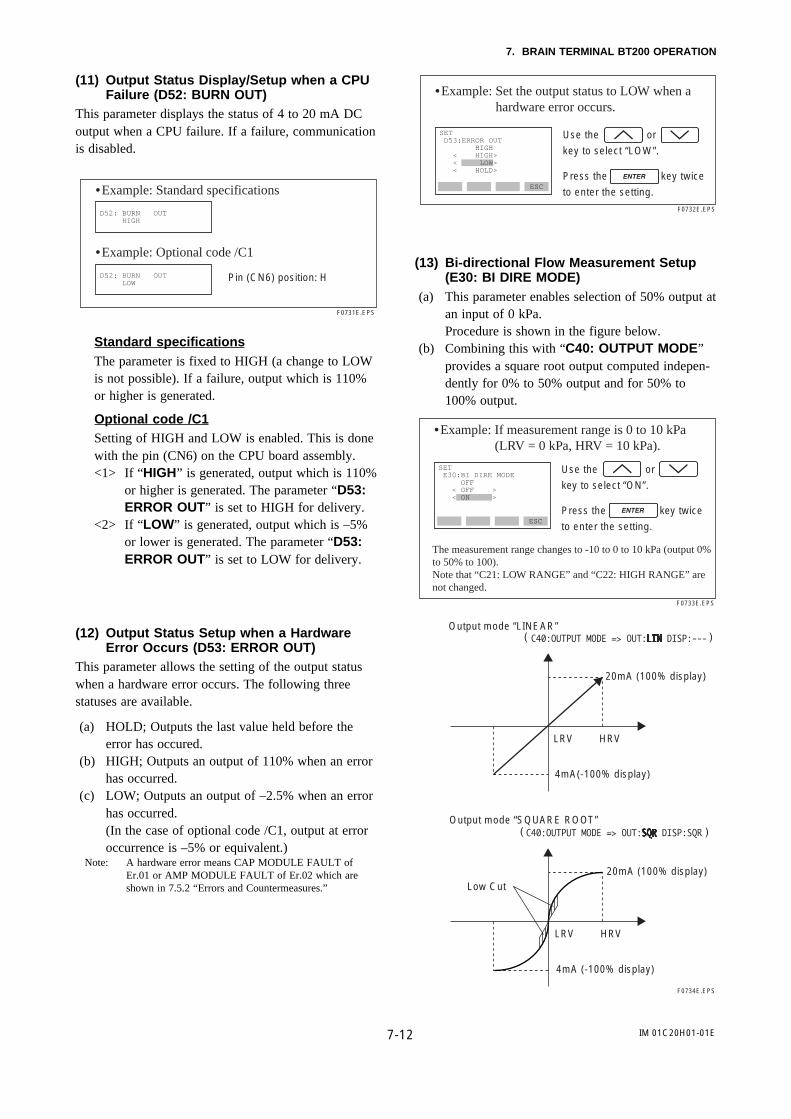
7-12
7. BRAIN TERMINAL BT200 OPERATION
IM 01C20H01-01E
(11) Output Status Display/Setup when a CPUFailure (D52: BURN OUT)
This parameter displays the status of 4 to 20 mA DCoutput when a CPU failure. If a failure, communicationis disabled.
D52: BURN OUT HIGH
D52: BURN OUT LOW
•Example: Standard specifications
F0731E.EPS
•Example: Optional code /C1
Pin (CN6) position: H
Standard specificationsThe parameter is fixed to HIGH (a change to LOWis not possible). If a failure, output which is 110%or higher is generated.
Optional code /C1Setting of HIGH and LOW is enabled. This is donewith the pin (CN6) on the CPU board assembly.<1> If “HIGH” is generated, output which is 110%
or higher is generated. The parameter “D53:ERROR OUT” is set to HIGH for delivery.
<2> If “LOW” is generated, output which is –5%or lower is generated. The parameter “D53:ERROR OUT” is set to LOW for delivery.
(12) Output Status Setup when a HardwareError Occurs (D53: ERROR OUT)
This parameter allows the setting of the output statuswhen a hardware error occurs. The following threestatuses are available.
(a) HOLD; Outputs the last value held before theerror has occured.
(b) HIGH; Outputs an output of 110% when an errorhas occurred.
(c) LOW; Outputs an output of –2.5% when an errorhas occurred.(In the case of optional code /C1, output at erroroccurrence is –5% or equivalent.)
Note: A hardware error means CAP MODULE FAULT ofEr.01 or AMP MODULE FAULT of Er.02 which areshown in 7.5.2 “Errors and Countermeasures.”
ESC
SET D53:ERROR OUT HIGH < HIGH> < LOW> < HOLD>
•Example: Set the output status to LOW when a hardware error occurs.
Use the or
key to select “LOW”.
Press the key twice
to enter the setting.
F0732E.EPS
(13) Bi-directional Flow Measurement Setup(E30: BI DIRE MODE)
(a) This parameter enables selection of 50% output atan input of 0 kPa.Procedure is shown in the figure below.
(b) Combining this with “C40: OUTPUT MODE”provides a square root output computed indepen-dently for 0% to 50% output and for 50% to100% output.
ESC
SET E30:BI DIRE MODE OFF < OFF > < ON >
•Example: If measurement range is 0 to 10 kPa (LRV = 0 kPa, HRV = 10 kPa).
The measurement range changes to -10 to 0 to 10 kPa (output 0% to 50% to 100).Note that “C21: LOW RANGE” and “C22: HIGH RANGE” are not changed.
Use the or
key to select “ON”.
Press the key twice
to enter the setting.
F0733E.EPS
20mA (100% display)
4mA(-100% display)
Output mode “LINEAR”
LRV HRV
F0734E.EPS
20mA (100% display)Low Cut
4mA (-100% display)
Output mode “SQUARE ROOT”
LRV HRV
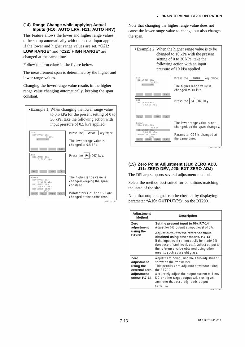
7-13
7. BRAIN TERMINAL BT200 OPERATION
IM 01C20H01-01E
(14) Range Change while applying ActualInputs (H10: AUTO LRV, H11: AUTO HRV)
This feature allows the lower and higher range valuesto be set up automatically with the actual input applied.If the lower and higher range values are set, “C21:LOW RANGE” and “C22: HIGH RANGE” arechanged at the same time.
Follow the procedure in the figure below.
The measurement span is determined by the higher andlower range values.
Changing the lower range value results in the higherrange value changing automatically, keeping the spanconstant.
FEED NO OK
SET H10:AUTO LRV 0.5000 kPa
DATA DIAG PRNT ESC
PARAM H10:AUTO LRV 0.5000 kPa H11:AUTO HRV 30.500 kPa H60:SELF CHEC GOOD
ESC
SET H10:AUTO LRV 0 kPa + 0
•Example 1: When changing the lower range value to 0.5 kPa for the present setting of 0 to 30 kPa, take the following action with input pressure of 0.5 kPa applied.
F0735E.EPS
The higher range value is changed keeping the span constant.
Parameters C21 and C22 are changed at the same time.
Press the key twice.
The lower range value is changed to 0.5 kPa.
Press the (OK) key.
Note that changing the higher range value does notcause the lower range value to change but also changesthe span.
FEED NO OK
SET H11:AUTO HRV 10.000 kPa
DATA DIAG PRNT ESC
PARAM H10:AUTO LRV 0 kPa H11:AUTO HRV 10.000 kPa H60:SELF CHECK GOOD
ESC
SET H11:AUTO HRV 30 kPa + 30
•Example 2: When the higher range value is to be changed to 10 kPa with the present setting of 0 to 30 kPa, take the following action with an input pressure of 10 kPa applied.
The lower range value is not changed, so the span changes.
Parameter C22 is changed at the same time.
Press the key twice.
The higher range value is changed to 10 kPa.
Press the (OK) key.
F0736E.EPS
(15) Zero Point Adjustment (J10: ZERO ADJ,J11: ZERO DEV, J20: EXT ZERO ADJ)
The DPharp supports several adjustment methods.
Select the method best suited for conditions matchingthe state of the site.
Note that output signal can be checked by displayingparameter “A10: OUTPUT(%)” on the BT200.
Adjustment Method Description
Zero adjustment using the BT200.
Zero adjustment using the external zero-adjustment screw. P.7-14
Set the present input to 0%. P.7-14Adjust for 0% output at input level of 0%.
Adjust output to the reference value obtained using other means. P.7-14If the input level cannot easily be made 0% (because of tank level, etc.), adjust output to the reference value obtained using other means, such as a sight glass.
Adjust zero point using the zero-adjustment screw on the transmitter.This permits zero adjustment without using the BT200.Accurately adjust the output current to 4 mA DC or other target output value using an ammeter that accuratly reads output currents.
T0704E.EPS

7-14
7. BRAIN TERMINAL BT200 OPERATION
IM 01C20H01-01E
(a) Follow the procedure below when setting thepresent output to 0% (4 mA).
FEED NO OK
SET J10:ZERO ADJ 0.0 %
CLR ESC
SET J10:ZERO ADJ 0.0 % + 000.0
A10:OUTPUT (%) 0.5 %
A10:OUTPUT (%) 0.0 %
Press the key twice.
Zero adjustment is completed.
Press the (OK) key.
F0737E.EPS
Output is 0.5%.
Output is 0%.
(b) In tank level measurement, if the actual levelcannot be brought to zero for zero adjustment,then the output can be adjusted to correspond tothe actual level obtained using another measuringinstrument such as a sight glass.
100%
0%
Present level 45%
Present level : 45%Present output : 41%
DPharp
F0738E.EPS
(b)-1Follow the procedure below to use“J10: ZERO ADJ”.
CLR ESC
SET J10:ZERO ADJ 0.0 % + 045.0
F0739E.EPS
A10:OUTPUT (%) 41.0 %
A10:OUTPUT (%) 45.0 %
Enter the present actual level, 45%.
Press the key twice.
The output is changed to 45%.
Present output is 41.0%.
(b)-2Follow the procedure below to use“J11: ZERO DEV.”.
ECS
ESC
SET J11:ZERO DEV. 2.50 % 0
A10:OUTPUT (%) 41.0 %
A10:OUTPUT (%) 45.0 %
SET J11:ZERO DEV. 2.50 % 6.50
Output error = 45.0–41.0 = 4.0%
Correction = previous correction+ output error = 2.50+4.0 = 6.50%
“J11: ZERO DEV.” contains the previous correction.
Set the correction value to 6.50.
Press the key twice.
F0740E.EPS
Present output is 41.0%.
The output is changed to 45%.
(c) Zero Point Adjustment Using the External ZeroAdjustment Screw• Enabling/inhibiting zero point adjustment
using the external zero-adjustment screw onthe transmitter (J20:EXT ZERO ADJ)Follow the procedure below to enable orinhibit zero point adjustment from the zero-adjustment screw on the transmitter.This is set to “ENABLE” when the instrumentis shipped.When zero adjustment from the external zeroadjustment screw is enabled, “E. ZERO” isdisplayed on the integral indicator.
ESC
SET J20:EXIT ZERO ADJ ENABLE < ENABLE > < INHIBIT>
•Example: Inhibiting zero adjustment by the external zero-adjustment screw.
Use the or
key to select “INHIBIT”.
Press the key twice
to enter the setting.
F0741E.EPS

7-15
7. BRAIN TERMINAL BT200 OPERATION
IM 01C20H01-01E
• Zero point adjustment using external zero-adjustment screw on the transmitterTurn the zero-adjustment screw on the outsideof the transmitter case using a slotted screw-driver. Turn the screw to the right to increasethe zero point or to the left to decrease thezero output; the zero adjusts in increments of0.01% of the range setting.Note that the amount of adjustment to the zeropoint changes according to the speed at whichthe screw is turned. To make fine adjustments,turn the screw slowly; to make coarse adjust-ments, turn the screw quickly.
Note : When a zero point adjustment has been made, do not turnoff the transmitter less than 30 seconds after adjustment.
Zero-adjustment screwF0742.EPS
(16) Test Output Setup (K10: OUTPUT X%)This feature can be used to output a fixed current from3.6 mA (–2.5%) to 21.6 mA (110%) for loop checks.
ESC
SET K10:OUTPUT X % 50.0 % ACTIVE
FEED NO OK
SET K10:OUTPUT X % 0.0 % + 050.0
•Example: Output 12 mA (50%) fixed current.
Set “50.0%”.
Press the key twice
to output a fixed current at 50%.
“Active” is displayed while this is being executed.
Press the (OK) key to
cancel the fixed current output.
F0743E.EPS
IMPORTANT
1. Test output is held for approximately 10minutes, and then released automaticallyafter the time has elapsed. Even if the BT200power supply is turned off or the communica-tion cable is disconnected during test output,it is held for approximately 10 minutes.
2. Press the (OK) key to release test output
immediately.
(17) Ambient Temperature Zero Shift Compen-sation
This function is used to compensate the zero shift bythe ambient temperature effect on the capillary tubes.
<1> DFS Mode Setup (E10: DFS MODE)When using the function, set the DFS MODE to“ON” to enable or “OFF” to disable.To set to “ON”, follow the procedure below.
ESC
SET E10:DFS MODE OFF < OFF > < ON >
F0744E.EPS
<1> Set the DFS mode to “ON”.
Use the or
key to select “ON”.
Press the key twice
to enter the setting.
Press the (OK) key.
<2> Reference Temperature Sensor Setup (E14:TEMP SELECT)“CAP. TEMP” is selected for use.Follow the procedure below.
ESC
SET E14:TEMP SELECT AMP.TEMP < AMP.TEMP > < CAP.TEMP >
F0745E.EPS
<2> Set the TEMP SELECT to “CAP.TEMP”.
Use the or
key to select “CAP.TEMP”.
Press the key twice
to enter the setting.
Press the (OK) key.
<3> Zero Shift Compenation Setup (E15: TEMPZERO)Obtain the compensation value of K from theequation (1) below. Then enter the value toexecute. The value can be rounded off to twodecimal places.
K= – × 100 • • • • • • (1)h × BSpan

7-16
7. BRAIN TERMINAL BT200 OPERATION
IM 01C20H01-01E
Where,h: Distance from high side of diaphragm seal tolow side of diaphragm seal(m).B: Constant value of fill fluid (see Table A.below)span: |HRV–LRV|Example: When h = 3 m, fill fluid code A, andspan = 15 kPa,
K = – × 100 = – 0.15(3) × 0.0074515
ESC
F0746E.EPS
CLR
SET E15:TEMP ZERO 0.00 -0.15
<3> Enter the value of K obtained from the equation (1).
Enter “-0.15”.
Press the key twice
to enter the setting.
Press the (OK) key.
F0747E.EPS
Low side
High side
Transmitter body
h
Note1: The function is engaged in a built-in temperature sensorin the transmitter body. The temperature deviationbetween the transmitter body and capillaries should beminimized to achieve optimal performance of thefunction.
Note2: When the span changes, reenter the newly obtained valueof K to E15: TEMP ZERO.
Table A. Constant Value [B] of Fill Fluid
Fill fluid code
Co
nst
ant
valu
e [B
]
A, C, 1, 2 B D E, P
mmH2O
kgf/cm2
kPa
mBar
atm
inH2O
psi
mmHg
0.76
0.000076
0.00745
0.07453
0.000074
0.02992
0.00108
0.05592
0.87
0.000087
0.00853
0.08532
0.000084
0.03425
0.00124
0.06401
1.45
0.000145
0.01422
0.14220
0.000140
0.05709
0.00206
0.10669
0.75
0.000075
0.00736
0.07355
0.000073
0.02953
0.00167
0.05518
T0706E.EPS
Note : Select the constant value of [B] from the actual unit used shown in the table.
(18) User Memo Fields (M: MEMO)This feature provides 5 user memo fields, each holdingup to 8 alphanumeric characters. Up to 5 items such asinspection date, inspector, and other information can besaved in these fields.
DATA DIAG PRNT ESC
SET M10:MEMO 1
00.4.1_
ESC
PARAM M10:MEMO 1
M20:MEMO 2
M30:MEMO 3
•Example: Save an inspection date of April 1, 2000.
Set “00.4.1” in the order of year, month, and day.
Press the key twice
to enter the setting.
F0748E.EPS
7.4 Displaying Data Using theBT200
7.4.1 Displaying Measured Data
The BT200 can be used to display measured data.
The measured data is updated automatically every 7seconds.
In addition, the display can be updated to the present
data value at any time by pressing the (DATA)
key. For parameters associated with the display ofmeasured data, see the Parameter Summary later in thismanua1.
DATA DIAG PRNT ESC
PARAM A10:OUTPUT (%) A11:ENGR.OUTPUT A20:AMP TEMP
HOME SET ADJ ESC
MENU A:DISPLAY B:SENSOR TYPE
PARAM A10:OUTPUT (%) XX.X % A11:ENGR.OUTPUT YY.Y % A20:AMP TEMP ZZ deg C
communi
•Example: Display output.
F0749E.EPS
Data is updated automatically at 7-secondintervals.
display “A10 : OUTPUT (%)”.

7-17
7. BRAIN TERMINAL BT200 OPERATION
IM 01C20H01-01E
7.4.2 Display Transmitter Model andSpecifications
The BT200 can be used to display the model andspecifications of the transmitter.
HOME SET ADJ ESC
MENU A:DISPLAY B:SENSOR TYPE
DATA DIAG PRNT ESC
PARAM B10:MODEL EJ118W-DM B11:STYLE NO. S2.XX B20:LRL – 98.07 kPa
•Example: View transmitter model name.
For the associated parameters, see the Parameter Summary later in this manual.
F0750E.EPS
7.5 Self-Diagnostics
7.5.1 Checking for Problems
(1) Identifying Problems with BT200The following four areas can be checked.
(a) Whether connections are good. (b) Whether BT200 was properly operated. (c) Whether settings were properly entered. (d) History of the errors.Refer to the following examples.
ESC
communication error
––WELCOME––BRAIN TERMINAL ID: BT200
check connection push ENTER key
UTIL FEED
•Example 1: Connection errors
Connect the BT200 to the transmitter.
Press the key.
When the panel shown on the left
appears, press the key.
Since communications will be unsuccessful if there is a problem in the connection to the BT200, the display at the left will appear.
Recheck the connection.
Press the (ESC) key.
F0751E.EPS
DATA DIAG PRNT ESC
PARAM C20:PRESS UNIT kPa C21:LOW RANGE 600 kPa C22:HIGH RANGE 600 kPa
FEED PRNT ESC
DIAG C60:SELF CHECK ERROR < ERROR > < ILLEGAL LRV >
OK
PARAM 01:MODEL EJ118W-DM 02:TAG NO. YOKOGAWA 03:SELF CHECK ERROR
•Example 2: Setting entry errors
F0752E.EPS
The initial data panel shows the result of current DPharp diagnostics.
Press the (DIAG) key in the
parameter panel to go to the diagnostics panel (C60: SELF CHECK).
An error message is displayed when an error occurs in the diagnostics panel.

7-18
7. BRAIN TERMINAL BT200 OPERATION
IM 01C20H01-01E
HOME SET ADJ ESC
MENU J:ADJUST K:TEST M:MEMO P:RECORD
DATA DIAG PRNT ESC
PARAM P10:ERROR REC 1 ERROR P11:ERROR REC 2 ERROR P12:ERROR REC 3 GOOD
ESC
SET P10:ERROR REC 1 ERROR < ERROR > < ILLEGAL LRV > < ILLEGAL HRV >
•Example 3: Checking the history of the errors
Connect the BT200 to the transmitter, and call item “P”.
Setting P10: “ERROR REC 1” displays the last error.P11: “ERROR REC 2” displays the error one time
before the last error occurred.P12: “ERROR REC 3” displays the error two times
before the last error occurred.P13: “ERROR REC 4” displays the error three
times before the last error occurred.The history of up to four errors can be stored.When the 5th error has occurred, it is stored in “P10”. The error stored in “P13” will be deleted, and then, the error in “P12” will be copied to “P13”.In this sequence, the history of the most previously occurred error will be removed from memory.“GOOD” will be displayed if there was no previous error.
Select P10: ERROR REC 1 and press the key to displsy error information.
F0753E.EPS
The display and the contents of the error messages are those shown in 8.5.2 “Error and Countermeasures”.
<1> SETUP PANEL
Note 1: Press the key twice in the setting panel (panel 1) to clear all error message (P10 to P13) information.
Note 2: After two hours from when an error occurs, the error message of that error will be recorded.Therefore, if you switch off the transmitter within two hours from when the error occurs, there is no history of that error stored in the transmitter, and this function is meaningless.
CAP MODULE FAULTAMP MODULE FAULTOUT OF RANGEOUT OF SP RANGEOVER TEMP (CAP)OVER TEMP (AMP)
OVER OUTPUTOVER DISPLAYILLEGAL LRVILLEGAL HRVILLEGAL SPANZERO ADJ OVER
(2) Checking with Integral Indicator
NOTE
If an error is detected in the self-diagnostic, anerror number is displayed on the integral indica-tor. If there is more than one error, the errornumber changes at two-second intervals.See Table 7.5.2 regarding the error numbers.
F0754E.EPS
Figure 7.5.1 Identifying Problems Using the IntegralIndicator
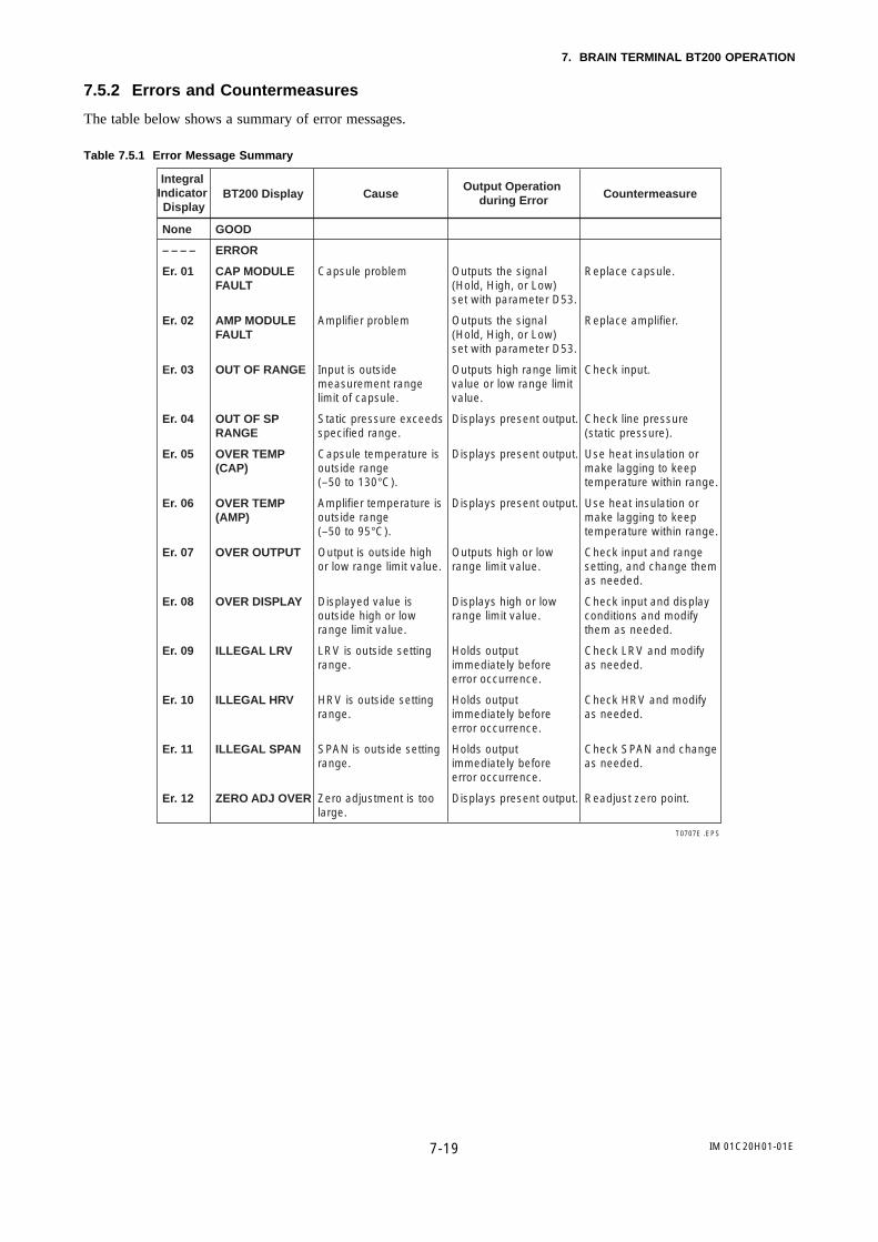
7-19
7. BRAIN TERMINAL BT200 OPERATION
IM 01C20H01-01E
7.5.2 Errors and Countermeasures
The table below shows a summary of error messages.
Table 7.5.1 Error Message Summary
Integral Indicator Display
BT200 Display Cause CountermeasureOutput Operation
during Error
None
– – – –
Er. 01
Er. 02
Er. 03
Er. 04
Er. 05
Er. 06
Er. 07
Er. 08
Er. 09
Er. 10
Er. 11
Er. 12
GOOD
ERROR
CAP MODULE FAULT
AMP MODULE FAULT
OUT OF RANGE
OUT OF SP RANGE
OVER TEMP (CAP)
OVER TEMP (AMP)
OVER OUTPUT
OVER DISPLAY
ILLEGAL LRV
ILLEGAL HRV
ILLEGAL SPAN
ZERO ADJ OVER
Capsule problem
Amplifier problem
Input is outside measurement range limit of capsule.
Static pressure exceeds specified range.
Capsule temperature is outside range (–50 to 130°C).
Amplifier temperature is outside range (–50 to 95°C).
Output is outside high or low range limit value.
Displayed value is outside high or low range limit value.
LRV is outside setting range.
HRV is outside setting range.
SPAN is outside setting range.
Zero adjustment is too large.
Outputs the signal (Hold, High, or Low) set with parameter D53.
Outputs the signal (Hold, High, or Low) set with parameter D53.
Outputs high range limit value or low range limit value.
Displays present output.
Displays present output.
Displays present output.
Outputs high or low range limit value.
Displays high or low range limit value.
Holds output immediately before error occurrence.
Holds output immediately before error occurrence.
Holds output immediately before error occurrence.
Displays present output.
Replace capsule.
Replace amplifier.
Check input.
Check line pressure (static pressure).
Use heat insulation or make lagging to keep temperature within range.
Use heat insulation or make lagging to keep temperature within range.
Check input and range setting, and change them as needed.
Check input and display conditions and modify them as needed.
Check LRV and modify as needed.
Check HRV and modify as needed.
Check SPAN and change as needed.
Readjust zero point.
T0707E .EPS
IM 01C20H01-01E8-1
8. MAINTENANCE
8. MAINTENANCE
8.1 Overview
WARNING
Since the accumulated process fluid may betoxic or otherwise harmful, take appropriate careto avoid contact with the body, or inhalation ofvapors during draining condensate or ventinggas in transmitter pressure-detector section andeven after dismounting the instrument from theprocess line for maintenance.
Maintenance of the transmitter is easy due to itsmodular construction. This chapter describes theprocedures for calibration, adjustment, and the disas-sembly and reassembly procedures required forcomponent replacement.
Since the transmitters are precision instruments,carefully and thoroughly read the following sectionsfor proper handling during maintenance.
IMPORTANT
• As a rule, maintenance of this transmittershould be implemented in a maintenanceservice shop where the necessary tools areprovided.
• The CPU assembly contains sensitive partsthat may be damaged by static electricity.Exercise care so as not to directly touch theelectronic parts or circuit patterns on the board,for example, by preventing static electrificationby using grounded wrist straps when handlingthe assembly.Also take precautions such as placing a re-moved CPU assembly into a bag with anantistatic coating.
8.2 Calibration Instrument Selec-tion
Table 8.2.1 shows the instruments required for calibra-tion. Select instruments that will enable the transmitterto be calibrated or adjusted to the required accuracy.
The calibration instruments should be handled carefullyso as to maintain the specified accuracy.
8.3 CalibrationUse the procedure below to check instrument operationand accuracy during periodic maintenance or trouble-shooting.
<1> Connect the instruments as shown in Figure 8.3.1and warm up the instruments for at least fiveminutes.
IMPORTANT
1. To adjust the transmitter for highest accuracy,make adjustments with the power supplyvoltage and load resistance including leadwireresistance set close to the conditions underwhich the transmitter is installed.
2. If the measurement range 0% point is 0 kPa0 mmH2O or shifted in the positive direction(suppressed zero), the positive referencepressure should be applied on the highpressure side, as shown in the figure. If themeasurement range 0% point is shifted in thenegative direction (elevated zero), the positivereference pressure should be applied on thelow pressure side.
<2> Apply reference pressures of 0%, 25%, 50%,75%, and 100% of the measurement range to thetransmitter. Calculate the errors (differencesbetween digital voltmeter readings and referencepressures) as the pressure is increased from 0% to100% and is decreased from 100% to 0%, andconfirm that the errors are within the requiredaccuracy.

IM 01C20H01-01E8-2
8. MAINTENANCE
Table 8.2.1 Instruments Required for Calibration
Name RemarksYokogawa-recommended Instrument
Power supply Model SDBT or SDBS distributor
Load resistor
Model 2792 standard resistor [250 Ω ±0.005%, 3 W]
Load adjustment resistor [100 Ω ±1%, 1 W]
VoltmeterModel 2501 A digital multimeter Accuracy (10V DC range): ±(0.002% of rdg + 1 dgt)
Digital manometer
Model MT220 precision digital manometer1) For 10 kPa class
Accuracy: ±(0.015% of rdg + 0.015% of F.S.)±(0.2% of rdg + 0.1% of F.S.)
2) For 130 kPa classAccuracy: ±0.02% of rdg
±5digits±(0.2% of rdg + 0.1% of F.S.)
3) For 700 kPa classAccuracy: ±(0.02% of rdg + 3digits)
±5 digits ±(0.2% of rdg + 0.1% of F.S.)
4) For 3000 kPa classAccuracy: ±(0.02% of rdg + 10 digits)
±(0.2% of rdg + 0.1% of F.S.) 5) For 130 kPa abs class
Accuracy: ±(0.03% of rdg + 6 digits)
4 to 20 mA DC signal
Select a manometer having a pressure range close to that of the transmitter.
Pressure generator
Model 7674 pneumatic pressure standard for 200 kPa 2 kgf/cm2, 25 kPa 2500 mmH2OAccuracy: ±0.05% of F.S.
Requires air pressure supply.
Pressure source
Model 6919 pressure regulator (pressure pump)Pressure range: 0 to 133 kPa 1000 mmHg
Prepare the vacuum pump for negative pressure ranges.
Dead weight gauge tester 25 kPa 2500mmH2O Accuracy: ±0.03% of setting
Select the one having a pressure range close to that of the transmitter.
T0801E.EPS
for 0 to 10 kPafor -10 to 0 kPa
for 25 to 130 kPafor 0 to 25 kPafor -80 to 0 kPa
for 100 to 700 kPafor 0 to 100 kPafor -80 to 0 kPa
for 0 to 3000 kPafor -80 to 0 kPa
for 0 to 130 kPa abs
. . . . . . . . . . . . . .
. . . . . . . . . . . . . . . . . . . . . . . . . . . . . . . . . . . . . . . . . . . . . . . .
. . . . . . . . .
. . . . . . . . . . . . . . . . . . . . . . . . . . . . . . . . . . . . . .
. . . . . . . . .
. . . . . . . . . . . . . . . . . . . .
. . . . . . . . . . . .
Note 1: The above table contains the instrumentscapable of performing calibration to the 0.2%level. Since special maintenance and manage-ment procedures involving traceability of eachinstrument to higher-level standards arerequired for calibration to the 0.1% level,there are difficulties in calibration to this levelin the field.For calibration to the 0.1% level, contactYokogawa representatives from which theinstrument was purchased or the nearestYokogawa office.
Note 2: If a liquid column manometer is to be usedfor calibration as a calibration manometer, itsreadings must be corrected to achieve propercalibration as shown below.
The formula below is for the case of a mercurymanometer with a brass scale.
Ls=L1–0.000163 (t–t0) – 0.00026cos2∅ – 2h×10–7
where
∅ : Latitudet : Working temperature, °Ct0 : Manometer reference temperature, °Ch : Altitude, mL : Liquid column reading, mLs : Liquid column (m) reading converted to h=0m,
∅ =45°Example :
• Correction for altitude and latitude in Tokyo isapproximately –0.09%.
• Correction at 23°C for a manometer with referencetemperature of 20°C is approximately –0.05%.

IM 01C20H01-01E8-3
8. MAINTENANCE
P
P
VRc R
F0801E.EPS
– +
Pressure source
If a pressure source and a manometer are combined:
Supply pressure
If a pressure generator is used:
Load adjustment resistor, 100Ω
Power supply E
Load resistor, 250Ω
Digital voltmeter
Mating calibration flange
High pressure side diaphragm seal
Low pressure side diaphragm seal
Precision digital manometer
Pneumatic pressure generator
Figure 8.3.1 Instrument Connections
8.4 Disassembly and Reassem-bly
CAUTION
Cautions for Flameproof Type Transmitters1. Flameproof type transmitters must be, as a
rule, removed to a non-hazardous area formaintenance and be disassembled andreassembled to the original state. For details,see “Installation and Operating Precautionsfor Intrinsically Safe Explosion-ProtectedInstruments” and “Instllation and OperatingPrecautions for Flameproof Explosion-Protected Instruments” at the end of thismanual.
2. When servicing a flameproof type transmitter,always detach the shrouding washers beforeremoving the cover, and never fail to re-tighten them after replacing the cover.
This section describes procedures for disassembly andreassembly for maintenance and component replace-ment.
Always turn OFF power and shut off and releasepressures before disassembly and reassembly. Useproper tools for all operations. Table 8.4.1 shows thetools required.
Table 8.4.1 Tools for Disassembly and Reassembly
Tool RemarksQuantity
Phillips screwdriver
Slotted screwdriver
Allen wrenches
Wrench
Torque wrench
Adjustable wrench
Socket wrench
Tweezers
1
1
3
1
1
1
1
1
JIS B4633, No. 2
JIS B4648One each, nominal 2, 4, and 5mm Allen wrenches
Width across flats, 19mm
Width across flats, 6mm
T0802E.EPS
8.4.1 Replacing the Integral Indicator
This subsection describes the procedure for replacingan integral indicator.
CAUTION
Cautions for Flameproof Type TransmittersUsers are prohibited by law from modifying theconstruction of a flameproof type transmitter.Thus the user is prohibited from using a flame-proof type transmitter with its integral indicatorremoved, or from adding an integral indicator toa transmitter. If such modification is absolutelyrequired, contact Yokogawa.
Removing the Integral Indicator<1> Remove the cover.<2> Supporting the integral indicator by hand, loosen
its two mounting screws.<3> Dismount the LCD board assembly from the CPU
board assembly.When doing this, carefully pull the LCD boardassembly straight forward so as not to damage theconnector between it and the CPU board assem-bly.

IM 01C20H01-01E8-4
8. MAINTENANCE
Attaching the Integral Indicator<1> Align both the LCD board assembly and CPU
board assembly connectors and engage them.<2> Insert and tighten the two mounting screws.<3> Replace the cover. (See Figure 8.4.1.)
F0802E.EPS
Cover
Integral indicator
Mounting screw
LCD board assembly
Connectors
Figure 8.4.1 Removing and Attaching Integral Indicator
8.4.2 Replacing the CPU Board Assembly
This subsection describes the procedure for replacingthe CPU board assembly.
Removing the CPU Board Assembly<1> Remove the cover.
If an integral indicator is mounted, refer toSubsection 8.4.1 and remove the indicator.
<2> Turn the zero-adjustment screw to the position(where the screw head slot is horizontal) shownin Figure 8.4.2.
<3> Disconnect the output terminal cable (cable withbrown connector at the end).When doing this, lightly press the side of theCPU board assembly connector and pull the cableconnector to disengage. (See Figure 8.4.3.)
<4> Disconnect the flat cable (cable with blackconnector at the end) that connects the CPUboard assembly and the capsule.
<5> Use a socket wrench (width across flats, 6mm) toloosen the two bosses.
<6> Carefully pull the CPU board assembly straightforward to remove it.
NOTE
Be careful not to apply excessive force to theCPU board assembly when removing it.
F0803E.EPS
Figure 8.4.2 Zero-Adjustment Screw
Mounting the CPU Board Assembly<1> Connect the flat cable (with black connector)
between the CPU board assembly and thecapsule.
<2> Connect the output terminal cable (with brownconnector).There is a slit in the CPU board assembly intowhich this cable should be fitted during assembly.
NOTE
Do not fail to confirm that the cables are free ofpinching between the case and the CPU boardassembly edge.
<3> Align and engage the zero adjustment screw withthe bracket on the CPU board assembly.Insert the CPU board assembly straight onto thepost in the amplifier case.
<4> Tighten the two bosses.If the transmitter is equipped with an integralindicator, refer to Subsection 8.4.1 to mount theindicator.
<5> Replace the cover.
F0804E.EPS
Output terminal cable
Cover
Integral indicator
Mounting screw
Flat cable
Flat cable
Post
BossCPU board assembly
Press forward
Figure 8.4.3 Removing and Mounting the CPU BoardAssembly

IM 01C20H01-01E8-5
8. MAINTENANCE
8.5 TroubleshootingIf any abnormality appears in the measured values, usethe troubleshooting flow chart below to isolate andremedy the problem. Since some problems havecomplex causes, it will not be possible to identify allusing this flow chart. If you have difficulty isolating orcorrecting a problem, contact Yokogawa servicepersonnel.
8.5.1 Basic Troubleshooting
If abnormal indication is encountered in measuredvalues, first determine whether the process variable isactually abnormal or a problem exists in the measure-ment system. If it can be decided that the problem is inthe measurement system, next isolate the problem anddecide what remedial action to take.
This transmitter is equipped with a self-diagnosticfunction which will be useful in troubleshooting; seeSection 8.5 for information on using this function.
Abnormalities appear in measurement.
: Areas where self-diagnostic offers support
Is process variable itself abnormal?
Inspect the process system.
Isolate problem in measurement system.
Does problem exist in receiving instrument?
Check transmitter.
Inspect receiver.
Check / correct operating conditions.
Y
Y
N Measurement system problem
N
Operating conditions
Environmental conditions
F0805E.EPS
Check / correct environmental conditions.
Transmitter itself
Figure 8.5.1 Basic Flow and Self-Diagnostics
8.5.2 Troubleshooting Flow Charts
F0806E.EPS
Connect BRAIN TERMINAL and check self-diagnostics.
NO
YES
YES
YES
YES
NO
NO
NO
Contact Yokogawa service personnel.
Does the self-diagnostic indicate problem location?
Is power supply polarity correct?
Are power supply voltage and load
resistance correct?
Is there continuity through the
transmitter loop wiring? Do the loop numbers
match?
Refer to error message summary in Subsection 7.5.2 to take action.
Refer to Section 5.3 to check / correct polarity at each terminal from power supply to the terminal box.
Refer to Section 5.6 for rated voltage and load resistance.
Find / correct broken conductor or wiring error.
The following sorts of symptoms indicate that transmitter may not be operating properly.Example: •There is no output signal.
•Output signal does not change even though process variable is known to be varying.•Output value is inconsistent with value inferred for process variable.

IM 01C20H01-01E8-6
8. MAINTENANCE
F0807E.EPS
Connect BRAIN TERMINAL and check self-diagnostics.
NO
YES
YES
YES
YES
NO
NO
YES
NO
NO
Contact Yokogawa service personnel.
Does the self-diagnostic indicate problem location?
Are high and low pressure side
diaphragm seals correctly connected to the
process?
Is power supply polarity correct?
Is the liquid level as specified?
Is zero point adjusted correctly?
Refer to error message summary in Subsection 7.5.2 to take action.
Check / correct polarity at each terminal from power supply to the terminal box.
Use the transmitter within the measurementrange shown onthe data plate.
Adjust the zero point.
Check the connections.
Output travels beyond 0% or 100%.
F0808E.EPS
Connect BRAIN TERMINAL and check self-diagnostics.
NO
YES
NO
YES
YES
NO
YES
NO
YES
NO
YES
Does the self-diagnostic indicate the
problem location?
Is external noise contained in the
output?
Are power supply voltage
and load resistance correct?
Are excess capillaries secured?
Does the ambient temperature
significantly differ between the high and low pressure
side capillaries?
Is transmitter installed where there is
marked variation in temperature?
Refer to error message summary in Subsection 7.5.2 to take action.
Refer to Section 5.6 to obtain the rated voltage and load resistance.
Avoid noise by providing complete grounding, or using shielded wires.
Secure them so that they are not moved by wind or vibration.
Provide lagging and / or neat insulation, or allow adequate ventilation.
Refer to Section 8.2 when selecting instruments for calibration.
NO
YES
NO
Contact Yokogawa service personnel.
Were appropriate instruments used for
calibration?
YES
NOIs output adjusted correctly?
Adjust the output.
Large output error.
Bind capillaries together as far as possible or provide lagging.
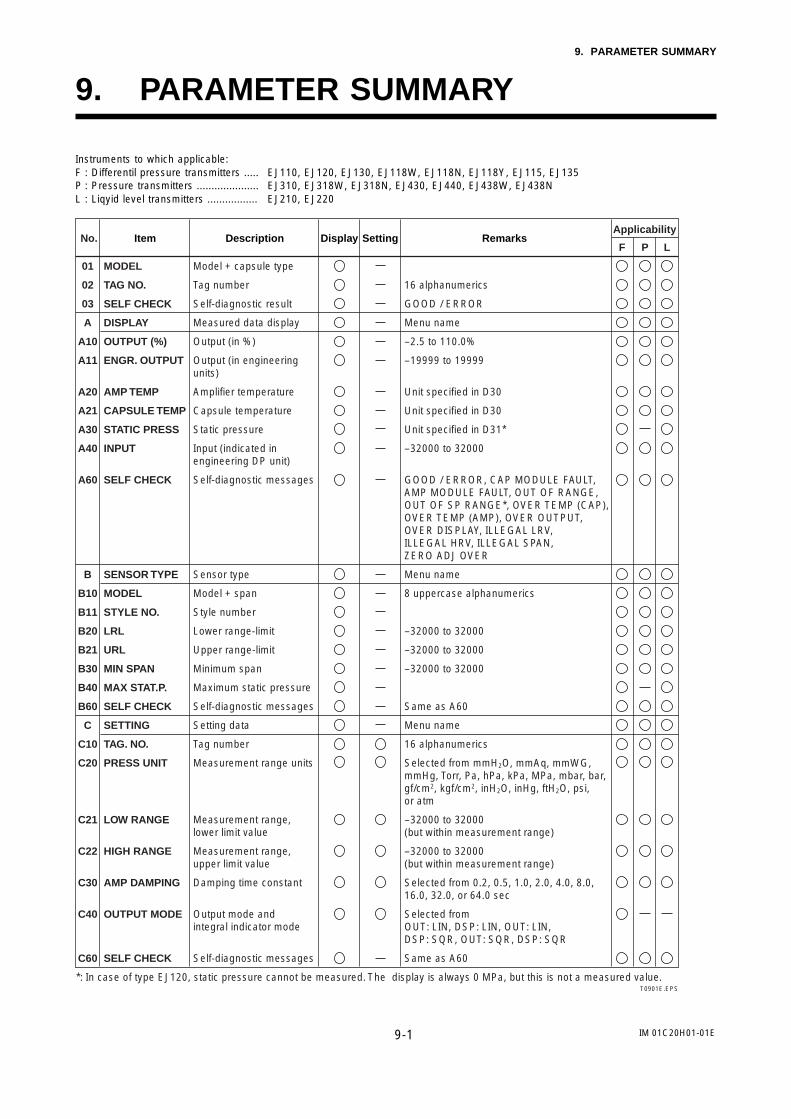
IM 01C20H01-01E9-1
9. PARAMETER SUMMARY
9. PARAMETER SUMMARY
Instruments to which applicable:F : Differentil pressure transmitters ..... EJ110, EJ120, EJ130, EJ118W, EJ118N, EJ118Y, EJ115, EJ135P : Pressure transmitters ..................... EJ310, EJ318W, EJ318N, EJ430, EJ440, EJ438W, EJ438NL : Liqyid level transmitters ................. EJ210, EJ220
T0901E.EPS
No.P LF
DescriptionApplicability
Display Setting RemarksItem
01
02
03
A
A10
A11
A20
A21
A30
A40
A60
B
B10
B11
B20
B21
B30
B40
B60
C
C10
C20
C21
C22
C30
C40
C60
MODEL
TAG NO.
SELF CHECK
DISPLAY
OUTPUT (%)
ENGR. OUTPUT
AMP TEMP
CAPSULE TEMP
STATIC PRESS
INPUT
SELF CHECK
SENSOR TYPE
MODEL
STYLE NO.
LRL
URL
MIN SPAN
MAX STAT.P.
SELF CHECK
SETTING
TAG. NO.
PRESS UNIT
LOW RANGE
HIGH RANGE
AMP DAMPING
OUTPUT MODE
SELF CHECK
Model + capsule type
Tag number
Self-diagnostic result
Measured data display
Output (in %)
Output (in engineering units)
Amplifier temperature
Capsule temperature
Static pressure
Input (indicated in engineering DP unit)
Self-diagnostic messages
Sensor type
Model + span
Style number
Lower range-limit
Upper range-limit
Minimum span
Maximum static pressure
Self-diagnostic messages
Setting data
Tag number
Measurement range units
Measurement range, lower limit value
Measurement range, upper limit value
Damping time constant
Output mode and integral indicator mode
Self-diagnostic messages
16 alphanumerics
GOOD / ERROR
Menu name
–2.5 to 110.0%
–19999 to 19999
Unit specified in D30
Unit specified in D30
Unit specified in D31*
–32000 to 32000
GOOD / ERROR, CAP MODULE FAULT, AMP MODULE FAULT, OUT OF RANGE, OUT OF SP RANGE*, OVER TEMP (CAP), OVER TEMP (AMP), OVER OUTPUT, OVER DISPLAY, ILLEGAL LRV, ILLEGAL HRV, ILLEGAL SPAN, ZERO ADJ OVER
Menu name
8 uppercase alphanumerics
–32000 to 32000
–32000 to 32000
–32000 to 32000
Same as A60
Menu name
16 alphanumerics
Selected from mmH2O, mmAq, mmWG, mmHg, Torr, Pa, hPa, kPa, MPa, mbar, bar, gf/cm2, kgf/cm2, inH2O, inHg, ftH2O, psi, or atm
–32000 to 32000(but within measurement range)
–32000 to 32000(but within measurement range)
Selected from 0.2, 0.5, 1.0, 2.0, 4.0, 8.0, 16.0, 32.0, or 64.0 sec
Selected fromOUT: LIN, DSP: LIN, OUT: LIN, DSP: SQR, OUT: SQR, DSP: SQR
Same as A60
*: In case of type EJ120, static pressure cannot be measured. The display is always 0 MPa, but this is not a measured value.
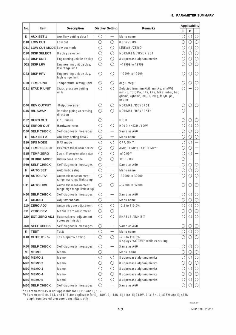
IM 01C20H01-01E9-2
9. PARAMETER SUMMARY
T0902E.EPS
No.P LF
DescriptionApplicability
Display Setting RemarksItem
D
D10
D11
D20
D21
D22
D23
D30
D31
D40
D45
D52
D53
D60
E
E10
E14
E15
E30
E60
H
H10
H11
H60
J
J10
J11
J20
J60
K
K10
K60
M
M10
M20
M30
M40
M50
M60
AUX SET 1
LOW CUT
LOW CUT MODE
DISP SELECT
DISP UNIT
DISP LRV
DISP HRV
TEMP UNIT
STAT. P. UNIT
REV OUTPUT
H/L SWAP
BURN OUT
ERROR OUT
SELF CHECK
AUX SET 2
DFS MODE
TEMP SELECT
TEMP ZERO
BI DIRE MODE
SELF CHECK
AUTO SET
AUTO LRV
AUTO HRV
SELF CHECK
ADJUST
ZERO ADJ
ZERO DEV.
EXT. ZERO ADJ
SELF CHECK
TEST
OUTPUT × %
SELF CHECK
MEMO
MEMO 1
MEMO 2
MEMO 3
MEMO 4
MEMO 5
SELF CHECK
Auxiliary setting data 1
Low cut
Low cut mode
Display selection
Engineering unit for display
Engineering unit display, low range limit
Engineering unit display, high range limit
Temperature setting units
Static pressure setting units
Output reversal
Impulse piping accessing direction
CPU failure
Hardware error
Self-diagnostic messages
Auxiliary setting data 2
DFS mode
Reference temperature sensor
Zero shift compensation setup
Bidirectional mode
Self-diagnostic messages
Automatic setup
Automatic measurement range low range limit setup
Automatic measurement range high range limit setup
Self-diagnostic messages
Adjustment data
Automatic zero adjustment
Manual zero adjustment
External zero-adjustment screw permission
Self-diagnostic messages
Tests
Tes output % setting
Self-diagnostic messages
Memo
Memo
Memo
Memo
Memo
Memo
Self-diagnostic messages
Menu name
0.0 to 20.0%
LINEAR / ZERO
NORMAL% / USER SET
8 uppercase alphanumerics
–19999 to 19999
–19999 to 19999
deg C/deg F
Selected from mmH2O, mmAq, mmWG, mmHg, Torr, Pa, hPa, kPa, MPa, mbar, bar, gf/cm2, kgf/cm2, inH2O, inHg, ftH2O, psi, or atm
NORMAL / REVERSE
NORMAL / REVERSE*
HIGH
HOLD / HIGH / LOW
Same as A60
Menu name
OFF, ON**
AMP. TEMP / CAP. TEMP**
±10.00**
OFF / ON
Same as A60
Menu name
–32000 to 32000
–32000 to 32000
Same as A60
Menu name
–2.5 to 110.0%
ENABLE / INHIBIT
Same as A60
Menu name
–2.5 to 110.0%Displays “ACTIVE” while executing
Same as A60
Menu name
8 uppercase alphanumerics
8 uppercase alphanumerics
8 uppercase alphanumerics
8 uppercase alphanumerics
8 uppercase alphanumerics
Same as A60
* : Parameter D45 is not applicable for EJ115 and EJ135.**: Parameter E10, E14, and E15 are applicable for EJ118W, EJ118N, EJ118Y, EJ318W, EJ318N, EJ438W and EJ438N
diaphragm sealed pressure transmitters only.

IM 01C20H01-01E10-1
10. GENERAL SPECIFICATIONS
10. GENERAL SPECIFICATIONS
10.1 Standard Specifications
Performance SpecificationsSee General Specifications sheet, GS 01C20H01-00E (Forwetted parts material code H, T, or U, refer toGS 01C20V01-00E).
Functional Specifications
Span and Range Limits:Capsule Measurement Span Measurement Range
V
2.5 to 130 kPa250 to 13000 mmH2O
14 to 700 kPa0.14 to 7 kgf/cm2
0.28 to 13.7 MPa2.8 to 140 kgf/cm2
130 to 130 kPa13000 to 13000 mmH2O
100 to 700 kPa1 to 7.0 kgf/cm2
0.1 to 13.7 MPa1 to 140 kgf/cm2
H
M
T1101E.EPS
Output Signal: 4 to 20 mA DC, 2-wire system
Failure Alarm:Output status at CPU failure;
Up-scale: 110%, 21.6 mA DC or more (fixed)Output status at Hardware error;
Up-scale: 110%, 21.6 mA DC (standard)Down-scale: –2.5%, 3.6 mA DC
Conditions of Communication Line:Power supply voltage;
18 to 42 V DC *Load resistance;
See Figure 10.1.Note: In case of an intrinsically safe transmitter, external load
resistance includes safety barrier resistance.Communication distance;
2 km *, when polyethylene-insulated PVC-sheathedcontrol (CEV) cables are used.
Load capacitance;0.22 F * or less.
Load inductance;3.3 mH * or less.
Spacing from power line;15 cm or more.* For general type and flameproof type.
Ambient Temperature Limits:–40 to 60C (–40 to 140F) (general-use type)–30 to 60C (–22 to 140F) (with integral indicator)
(See ‘Optional Specifications’ for Explosion-protectedtypes)Note: The ambient temperature limits must be within the fill
fluid operating temperature range, see Table 10.1.
Process Temperature Limits:See Table 10.1.
Ambient Humidity Limits:5 to 100% R.H. (at 40C)
Working Pressure Limits:2.7 kPa abs 20 mmHg abs to flange rating pressure.For atmospheric pressure or below, see Figure 10.2
Power Supply Effect:0.005%/V (21.6 to 32 V DC, 350 )
Mounting:Transmitter; 2-inch pipe mountingDiaphragm seals; flange mounting
Mounting Flange Rating:See ‘Model and Suffix Code.’Flanges conforming to ANSI are serrated on their gasketsurfaces (ANSI B16.5).Note: For model EJ118W with wetted parts material code H,
T, or U, no serration is done.
Explosion-protected Construction:See ‘Optional Specifications.’
Integral Indicator:LCD digital indicator (optional)
EMC Conformity Standards: AS/NZS CISPR11
Damping Time Constant:(Sum of time constants for amplifier assembly and capsuleassembly)
• Amplifier assembly time constant; Can be set in 9increments from 0.2 to 64 sec.
• Approximate capsule assembly damping time constantvalues obtained at normal temperature when thecapillary length is 3 m and the fill fluid code is A;
Capsule M
Time Constant(sec)
Approx.0.9
H
Approx.0.7
V
Approx.0.7
T1102E.EPS
External Zero Adjustment:Continuously adjustable
Resolution; 0.01% of span
Zero Adjustment Limits:Zero can be fully elevated or suppressed as long as low andhigh range values are within the measurement range limitsof the capsule.
Physical SpecificationsWetted Parts Materials:
Diaphragm and other wetted parts;See ‘Model and Suffix Codes’
Capillaries;JIS SUS316
Protection tubes;JIS SUS304, PVC-sheathed [Max. operating temperatureof PVC, 100C (212F)]
Fill fluid;See Table 10.1.

IM 01C20H01-01E10-2
10. GENERAL SPECIFICATIONS
Non-wetted Parts Materials:Transmitter cover flange;
JIS SUS316Transmitter cover flange bolts;
See ‘Model and Suffix Codes’
Degrees of Protection:IP67, NEMA4, JIS C0920
Painting:Polyurethane resin baked finish.
For case; frosty white (Munsell 2.5Y8.4/1.2)For cover: deep sea moss green (Munsell 0.6GY3.l /2.0)
Weight:[EJ118 with JIS 10K flange]
24.0 kg (52.9 lb) (with mounting bracket)Connections:
Refer to the ‘Model and Suffix Codes’ to specify the processand electrical connection type.
R=
250
600
12 17.9 42
Power supply voltage E (V DC)
Communicationapplicable
range
F1101E.EPS
26.2
E–120.0236External
load resistanceR ()
Figure 10.1 Relationship Between Power Supply Voltageand External Load Resistance
F1102E.EPS
Process temperaturefor fill fluid code B
Process temperaturefor fill fluid code A
Process temperaturefor fill fluid code C
Flange max.working pressure
Atmo-sphericpressure
Transmitter ambienttemperature range(For fill fluid code A, B)
2.7 20
Process Temperature (C)
Working pressurekPa abs
mmHg abs
100 750
0.1 0.75
1 7.5
10 75
50 0 50 100 150 200 250 300
Figure 10.2 Working Pressure and Process Temperature
Table 10.1 Process Temperature and Ambient Temperature
Silicone Oil Fluorinated Oil Ethylene Glycol
Fill FluidCode ‘A’
Fill FluidCode ‘B’
Fill FluidCode ‘C’
Fill FluidCode ‘D’
Fill FluidCode ‘E’
Processtemperature
-10 to 250 C(14 to 482 F)
-30 to 180 C(-22 to 356 F)
10 to 300 C(50 to 572 F)
-20 to 120 C(-4 to 248 F)
-50 to 100 C(-58 to 212 F)
Ambienttemperature
-10 to 60 C(14 to 140 F)
-15 to 60 C(5 to 140 F)
10 to 60 C(50 to 140 F)
-20 to 60 C(-4 to 140 F)
-40 to 60 C(-40 to 140 F)
Working pressure See Figure 10.251 kPa abs or more380 mmHg abs
Vacuum pressure notallowed
Specific gravity 1.07 0.94 1.09 1.90 to 1.92 1.09
T1103E.EPS
Table 10.2 Calibration Units
MeasurementSpan and
Range
Optional code
EJ1
18W
EJ1
18N
, Y
D1 (psi Unit) D3 (bar Unit) D4 (kgf/cm2 Unit)
MSpan 10 to 520 inH2O 25 to 1300 mbar 250 to 13000 mmH2O
Range -520 to 520 inH2O -1300 to 1300 mbar -13000 to 13000 mmH2O
HSpan 56 to 2800 inH 2O 140 to 7000 mbar 0.14 to 7 kgf/cm 2
Range -400 to 2800 inH 2O -1000 to 7000 mbar -1 to 7 kgf/cm 2
VSpan 40 to 2000 psi 2.8 to 137 bar 2.8 to 140 kgf/cm 2
Range -15 to 2000 psi -1 to 137 bar -1 to 140 kgf/cm 2
MSpan 10 to 520 inH2O 25 to 1300 mbar 250 to 13000 mmH2O
Range -520 to 520 inH2O -1300 to 1300 mbar -13000 to 13000 mmH2O
HSpan 56 to 2800 inH 2O 140 to 7000 mbar 0.14 to 7 kgf/cm 2
Range -400 to 2800 inH 2O -1000 to 7000 mbar -1 to 7 kgf/cm 2
T1108E.EPS

IM 01C20H01-01E10-3
10. GENERAL SPECIFICATIONS
10.2 Model and Suffix Codes
Model EJ118W
Model Suffix codes Description
EJ118W · · · · · · · · · · · · · · · · · · · · · · · · · · · · Diaphragm sealed differential pressure transmitter (Flush diaphragm type)
Output signal -D · · · · · · · · · · · · · · · · · · · · · · · · · · 4 to 20 mA DC with digital communication (BRAIN protocol)
Measurement span(capsule)
M · · · · · · · · · · · · · · · · · · · · · · · · · · H · · · · · · · · · · · · · · · · · · · · · · · · · · V · · · · · · · · · · · · · · · · · · · · · · · · · ·
2.5 to 130 kPa 250 to 13000 mmH2O14 to 700 kPa 0.14 to 7 kgf/cm20.28 to 13.7 MPa 2.8 to 140 kgf/cm2
Wetted parts material S · · · · · · · · · · · · · · · · · · · · · · ·
H · · · · · · · · · · · · · · · · · · · · · · ·T · · · · · · · · · · · · · · · · · · · · · · · U · · · · · · · · · · · · · · · · · · · · · · ·
Process flange rating J1 · · · · · · · · · · · · · · · · · · · · ·J2 · · · · · · · · · · · · · · · · · · · · · J4 · · · · · · · · · · · · · · · · · · · · · A1 · · · · · · · · · · · · · · · · · · · · · A2 · · · · · · · · · · · · · · · · · · · · ·A4 · · · · · · · · · · · · · · · · · · · · ·
JIS 10KJIS 20KJIS 40KANSI class 150ANSI class 300ANSI class 600
Process flange size/material
D · · · · · · · · · · · · · · · · · · · · E · · · · · · · · · · · · · · · · · · · ·
Installation -0 · · · · · · · · · · · -2 · · · · · · · · · · ·
Vertical impulse piping type, left side terminal boxVertical impulse piping type, right side terminal box
Electrical connection 0 · · · · · · · · · · 1 · · · · · · · · · · 2 · · · · · · · · · · 5 · · · · · · · · · · 6 · · · · · · · · · · 7 · · · · · · · · · ·
G 1/2 femaleG 3/4 female1/2 NPT female G 1/2 female, with external indicator connectionG 3/4 female, with external indicator connection1/2 NPT female, with external indicator connection
Integral indicator D · · · · · · · · N · · · · · · · ·
Digital indicator(None)
Mounting bracket A · · · · · B · · · · · N · · · · ·
T1104E.EPS
3-inch (80 mm)/ JIS S25C3-inch (80 mm)/ JIS SUS304
JIS SECC 2-inch pipe mounting (flat type)JIS SUS304 2-inch pipe mounting (flat type)(None)
[Diaphragm] [Others]JIS SUS316L JIS SUS316LHastelloy C-276 Hastelloy C-276Tantalum TantalumTitanium Titanium
Cover flange bolts material A · · · · · · · · · · · · · · · · · · B · · · · · · · · · · · · · · · · · ·
JIS SCM435JIS SUS630
Fill fluid
-A *1 · · · · · · · · · · · · · · · -B · · · · · · · · · · · · · · · · -C *2 · · · · · · · · · · · · · · ·-D *3 · · · · · · · · · · · · · · · -E · · · · · · · · · · · · · · · ·
––– A · · · · · · · · · · · · · · · Always A
Optional codes / Optional specification
Capillary length (m) · · · · · · · · · · · · Specify capillary length from 1 to 5 m in . (Example for 2 m: 02)
[Process [Ambienttemperature] temperature]
For general use (silicone oil) 10 to 250 C 10 to 60 CFor general use (silicone oil) 30 to 180 C 15 to 60 CFor high temperature use (silicone oil) 10 to 300 C 10 to 60 CFor oil-prohibited use (fluorinated oil) 20 to 120 C 10 to 60 CFor low temperature use (ethylene glycol) 50 to 100 C 40 to 60 C
Example: EJ118W-DMSJ1DA-AA02-02NA/
*1: In case of wetted parts material code T (Tantalum), the process temperature limit is -10 to 200 C.*2: Wetted parts material code T (Tantalum) cannot be applied.*3: Even in case where fill fluid code D (fluorinated oil) is selected, if degrease cleansing treatment for the wetted parts is required, specify
optional code K1.

IM 01C20H01-01E10-4
10. GENERAL SPECIFICATIONS
Model EJ118N and EJ118YModel Suffix codes Description
EJ118NEJ118Y
· · · · · · · · · · · · · · · · · · · · · · · · · · · · · · · · · · · · · · · · · · · · · · · · · ·
Diaphragm sealed differential pressure transmitter (Extended diaphragm type)Diaphragm sealed differential pressure transmitter(Combination of Extended diaphragm and flush diaphragm type)
Output signal -D · · · · · · · · · · · · · · · · · · · · · · · · 4 to 20 mA DC with digital communication (BRAIN protocol)
Measurement span(capsule)
M · · · · · · · · · · · · · · · · · · · · · · · H · · · · · · · · · · · · · · · · · · · · · · ·
2.5 to 130 kPa 250 to 13000 mmH2O14 to 700 kPa 0.14 to 7 kgf/cm2
Wetted parts material *1
Process flange rating J1 · · · · · · · · · · · · · · · · · · · ·J2 · · · · · · · · · · · · · · · · · · · ·A1 · · · · · · · · · · · · · · · · · · ·A2 · · · · · · · · · · · · · · · · · · · ·
Process flange size/material
G · · · · · · · · · · · · · · · · ·H · · · · · · · · · · · · · · · · ·P · · · · · · · · · · · · · · · · ·Q · · · · · · · · · · · · · · · · ·
Installation -0 · · · · · · · · · · -2 · · · · · · · · · ·
Vertical impulse piping type, left side terminal boxVertical impulse piping type, right side terminal box
Electrical connection 0 · · · · · · · · · 1 · · · · · · · · · 2 · · · · · · · · ·5 · · · · · · · · · 6 · · · · · · · · ·7 · · · · · · · · ·
G 1/2 femaleG 3/4 female1/2 NPT female G 1/2 female, with external indicator connectionG 3/4 female, with external indicator connection1/2 NPT female, with external indicator connection
Integral indicator D · · · · · · N · · · · · ·
Digital indicator(None)
Mounting bracket A · · · · B · · · · N · · · ·
4-inch (100 mm)/ JIS S25C4-inch (100 mm)/ JIS SUS304High side 4-inch (100 mm) and Low side 3-inch (80 mm)/JIS S25CHigh side 4-inch (100 mm) and Low side 3-inch (80 mm)/JIS SUS304
JIS SECC 2-inch pipe mounting (flat type)JIS SUS304 2-inch pipe mounting (flat type)(None)
Cover flange bolts material A · · · · · · · · · · · · · · · · B · · · · · · · · · · · · · · · ·
JIS SCM435JIS SUS630
Fill fluid
-A · · · · · · · · · · · · · · -B · · · · · · · · · · · · · ·-C · · · · · · · · · · · · · ·-D *2 · · · · · · · · · · · -E · · · · · · · · · · · · · ·
– B · · · · · · · · · · · · · Always B
Capillary length (m) · · · · · · · · · · Specify capillary length from 1 to 5 m in . (Example for 2 m: 02)
Diaphragm extension length
2 · · · · · · · · · · · · · · · · · · · ·4 · · · · · · · · · · · · · · · · · · · ·6 · · · · · · · · · · · · · · · · · · · ·
X2= 50.8 mmX2=101.6 mmX2=152.4 mm
T1105E.EPS
[Process [Ambienttemperature] temperature]
For general use (silicone oil) 10 to 250C 10 to 60CFor general use (silicone oil) 30 to 180C 15 to 60CFor high temperature use (silicone oil) 10 to 300C 10 to 60CFor oil-prohibited use (fluorinated oil) 20 to 120C 10 to 60CFor low temperature use (ethylene glycol) 50 to 100C 40 to 60C
Optional codes / Optional specification
[Diaphragm] [Pipe] [Others]JIS SUS316L JIS SUS316 JIS SUS316
JIS 10KJIS 20KANSI class 150ANSI class 300
S · · · · · · · · · · · · · · · · · · · · · ·
Example: EJ118Y-DMSJ12PA-AC02-02NA/
*1: For wetted parts material of EJ118Y low pressure side (Flush diaphragm): Diaphragm; SUS3l6L, Others; SUS316L.*2: Even in case where fill fluid code D (fluorinated oil) is selected, if degrease cleansing treatment for the wetted parts is required, specify
optional code K1.

IM 01C20H01-01E10-5
10. GENERAL SPECIFICATIONS
10.3 Optional Specifications
T1106E.EPS
Explosionproof type
JF3
FF1
Intrinsically safe type
JS11
FM Intrinsically Safe Approval Class I Division 1 groups A, B, C and D Class II Division 1 groups E, F and G, Class III Division 1 Vmax : 31.5 VDC Imax : 93 mA Pmax : 1.1 W Ci=2 nF Li=1.04 mH Temperature Class : T4 Outdoor hazardous locations (NEMA 4) Amb. Temp. : –20 to 60 C
FS1
Attached flameproof packingadapter *7
Electrical connection : G1/2 femaleApplicable cable O.D. : 8 to 12 mm
1 pc. G11
2 pcs. G12
Electrical connection : G3/4 femaleApplicable cable O.D. : 10 to 16 mm
1 pc. G21
2 pcs. G22
Item
Color change
Coating change
Lightning protector
Oil-prohibited use
Calibration units
No serration *1
Teflon film *2
Operating temperature correction *3
Capillary without PVC sheaths
CPU failure alarm down-scale *4
Gold-plate *5
Description
Amplifier cover only
Epoxy resin-baked coating
Transmitter power supply voltage: 12.5 to 32 V DC
Allowable current: Max. 6000 A (140 µs), Repeating 1000 A (140 µs) 100 times
Degrease cleaning treatment
P calibration (psi unit)
bar calibration (bar unit)
M calibration (kgf/cm2 unit)
No serration work on the flange gasket surface (for ANSI flange only)
With FEP film and flourinated oil
Working range: 20 to 150 °C, 0 to 2 MPa0 to 20 kgf/cm2 (Not usable under vaccum)
Adjusting range: 80 to Maximum temperature of specified fill fluid
When ambient temperature exceeds 100 °C, or use of PVC is prohibited
Output status at CPU failure and hardware error for –5%, 3.2 mA DC or less with attached user selectable high-low jumper switch.
Gold-plated Diaphragm
Code
P
X1
A
K1
D1
D3
D4
Q
T
R
V
C1
A1
(See Table 10.2)
Painting
TIIS Flameproof Approval, Ex do IIC T4X *6
Certificate: TC13810 (Without integral indicator) TC13811 (With integral indicator) Amb. Temp. : –20 to 60°C, Max. Process Temp. : 120°C
FM Explosionproof Approval Applicable standard: FM3600, FM3615, FM3810, NEMA 250, ANSI/NFPA 70 Class I, II and III, Division 1, Groups B, C, D, E, F and G. Outdoor hazardous locations (NEMA 4), Temperature class : T6 Electrical connection : 1/2 NPT female, Amb. Temp. : –40 to 60°C
TIIS Intrinsically Safe Approval, i3aG4 *8 *9
(Using Model BARD-800 safety barrier : Model BARD-400 can also be used.) Amb. Temp. : –10 to 60°C, Max. Process Temp. : 80°C
*1: Not applicable for model EJ118W with Wetted part material code H, T, or U.*2: Teflon film can only be specified for model EJ118W.*3: Specify the process operating temperature for zero correction.
Example: Zero correction by process temperature 90 C.*4: The direction of hardware error alarm is user selectable by BT200.*5: Applicable for wetted parts material code S.*6: In case the ambient temperature exceeds 50°C, use heat-resistant cables with maximum allowable temperature of 75°C or above.*7: If cable wiring is to be used to a TIIS flameproof type transmitter, do not fail to add the YOKOGAWA-assured flameproof packing
adapter.*8: The communication distance is about 800 m when using polyethylene-insulated PVC sheathed control (CEV) cables.*9: See certificate list of TIIS intrinsically safe approval below.
Without lightning protector(option code /A)
With lightning protector(option code /A)
Connection to BARD-800 Connection to BARD-400
T1109E.EPS
T56212T54512
T56213
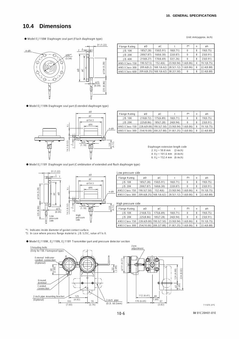
IM 01C20H01-01E10-6
10. GENERAL SPECIFICATIONS
10.4 Dimensions
T1107E.EPS
Flange Rating
JIS 10K
JIS 20K
JIS 40K
ANSI Class 150
ANSI Class 300
ANSI Class 600
øD
185(7.28)
200(7.87)
210(8.27)
190.5(7.5)
209.6(8.2)
209.6(8.25)
t
18(0.71)
22(0.87)
32(1.26)
23.9(0.94)
28.5(1.12)
38.2(1.50)
øC
150(5.91)
160(6.30)
170(6.69)
152.4(6)
168.1(6.62)
168.1(6.62)
n
8
8
8
4
8
8
øh
19(0.75)
23(0.91)
23(0.91)
19.1(0.75)
22.4(0.88)
22.4(0.88)
f*2
0
0
0
1.6(0.06)
1.6(0.06)
0
*2: In case where process flange material is JIS S25C, value of f is 0.
90*1
(3.54)
D
C
13
4 (5
.28)
225
(8.8
6)15(0.59)
t
31 (1.22)
n-h f
Unit: mm(approx. inch)
125(4.92)
193(7.60)
70(2.76)
112 (4.41) 48(1.89)
170 (6.69) 97(3.82)
224
(8.8
2)
124
(4.8
8)47
(1.8
5)
11
1 (4
.37)
68(2
.68)
53(
2.09
)
External indicatorconduit connection (Optional)
Groundterminal
2-inch pipe mounting bracket(Optional)
Conduitconnection
Zeroadjustment
2-inch pipe(O.D. 60.5mm)
Shrouding bolts(Only for TIIS Flameproof type)
*1: Indicates inside diameter of gasket contact surface.
Flange Rating
JIS 10K
JIS 20K
ANSI Class 150
ANSI Class 300
øD
210(8.72)
225(8.86)
228.6(9.00)
254(10.00)
t
18(0.71)
24(0.94)
23.9(0.94)
31.8(1.25)
øC
175(6.89)
185(7.28)
190.5(7.50)
200.2(7.88)
n
8
8
8
8
øh
19(0.75)
23(0.91)
19.1(0.75)
22.4(0.88)
f*1
0
0
1.6(0.06)
1.6(0.06)
Diaphragm extension length code2: X2 = 50.8 mm (2-inch)4: X2 = 101.6 mm (4-inch)6: X2 = 152.4 mm (6-inch)
120
(4.7
2)
t
96
D
C
154.5
X2
14.3
(0.
52)
n-h
HIGHfLOW
30(1.18)
120
(4.7
2)
t
96
D
C
154.5
X2
14.3
(0.
52)
n-h
HIGHf
30(1.18)
Model EJ118W Diaphragm seal part (Flush diaphragm type)
Model EJ118N Diaphragm seal part (Extended diaphragm type)
Model EJ118Y Diaphragm seal part (Combination of extended and flush diaphragm type)
Model EJ118W, EJ118N, EJ118Y Transmitter part and pressure detector section
Low pressure side
Flange Rating
JIS 10K
JIS 20K
ANSI Class 150
ANSI Class 300
øD
185(7.28)
200(7.87)
190.5(7.50)
209.6(8.25)
t
18(0.71)
22(0.87)
23.9(0.94)
28.5(1.12)
øC
150(5.91)
160(6.30)
152.4(6)
168.1(6.62)
n
8
8
4
8
øh
19(0.75)
23(0.91)
19.1(0.75)
22.4(0.88)
f*2
0
0
1.6(0.06)
1.6(0.06)
High pressure side
Flange Rating
JIS 10K
JIS 20K
ANSI Class 150
ANSI Class 300
øD
210(8.72)
225(8.86)
228.6(9.00)
254(10.00)
t
18(0.71)
24(0.94)
23.9(0.94)
31.8(1.25)
øC
175(6.89)
185(7.28)
190.5(7.50)
200.2(7.88)
n
8
8
8
8
øh
19(0.75)
23(0.91)
19.1(0.75)
22.4(0.88)
f*2
0
0
1.6(0.06)
1.6(0.06)
tf
Lowpressureside
Highpressureside
D
C
13
4 (5
.28)
225
(8.8
6)
15(0.59)
31 (1.22)

EX-A03E1
INSTALLATION AND OPERATING PRECAUTIONS FOR TIIS INTRINSICALLY SAFE EQUIPMENT
INSTALLATION AND OPERATING PRECAUTIONS FORTIIS INTRINSICALLY SAFE EQUIPMENT
Apparatus Certified Under Technical Criteria (IEC-compatible Standards)and from “RECOMMENDED PRACTICES for Explosion-Protected Electri-cal Installations in General Industries,” published in 1979
1. GeneralThe following describes precautions on electrical apparatusof intrinsically safe construction (hereinafter referred to asintrinsically safe apparatus).
Following the Labor Safety and Health Laws of Japan, anintrinsically safe apparatus must undergo type tests in orderto be certified by the Technical Institute of Industrial Safety,Inc. These tests are required to satisfy either the technicalcriteria for electrical machinery and equipment in compliancewith explosionproof standards involving inflammable gasesor vapors and for machinery and equipment havingexplosionproof performance (standards notification no. 556
from the Japanese Ministry of Labor) (hereinafter referred toas technical criteria), in conformity with IEC Standards, orthe “Recommended Practice for Explosion-ProtectedElectrical Installations in General Industries,” published in1979. Such a certified apparatus can be used in hazardouslocations where inflammable gases or vapors may be present.
Certified apparatus includes a certification label and anequipment nameplate with the specifications necessary forexplosion requirements as well as precautions on explosionprotection. Please confirm these precautionary items and usethem to meet specification requirements.
For electrical wiring and maintenance servicing, please referto “Internal Wiring Rules” in the Electrical InstallationTechnical Standards as well as “USER’S GUIDELINES forElectrical Installations for Explosive Gas Atmospheres inGeneral Industry,” published in 1994.
To meet intrinsically safe requirements, equipment that canbe termed an “intrinsically safe apparatus” must:
(1) be certified by the Technical Institute of IndustrialSafety, Inc. in accordance with the Labor Safety andHealth Laws of Japan and have the appropriate mark ofcertification labeled on its case, and
(2) be used in compliance with the specifications marked onits certification label, equipment nameplate and
precautionary information furnished.
Note: Intrinsically safe apparatus satisfy their performance underspecific conditions. They are not always absolutely safe underevery operational and environmental condition. In other
words, they are not safe products involved with factors suchas chemical reactions, geographical changes or the like otherthan affected by electric energy from the equipment itself.
2. Electrical Apparatus of IntrinsicSafety Type of Explosion-Pro-tected Construction
The intrinsic safety type of explosion-protected constructionis a method of protection applicable to a circuit or part of acircuit in which, under prescribed test conditions, no spark orthermal effect, whether produced normally or accidentally, iscapable of causing a prescribed explosive gas to ignite. Inother words, electrical apparatus of this construction isintended to suppress electrical energy thereby preventingignition of a given explosive gas atmosphere even though
spark or high thermal effect occurs in the electric circuitry.
Intrinsically safe electrical apparatus generally compriseintrinsically safe apparatus installed in a hazardous location
and a safety barrier (associated apparatus), installed in a non-hazardous location, aimed at preventing electrical energyfrom flowing into the electric circuitry of intrinsically safeapparatus.
However, battery-operated, portable intrinsically safeapparatus or the like may be used alone.
3. Terminology(1) Intrinsically safe apparatus: Electrical apparatus in which
all the circuits are intrinsically safe circuits.(2) Associated apparatus: Electrical apparatus in which there
are both intrinsically safe circuits and non-intrinsicallysafe circuits that can affect the safety of intrinsically safecircuits.
(3) Safety barrier: A specific type of associated apparatus,which consists mainly of safety barrier elements, andserves to limit the flow of excessive electrical energy,which is capable of causing ignition of a given explosivegas or vapour of a non-intrinsically safe circuit intoconcerned intrinsically safe circuits.
(4) Apparatus of category “ia”: Intrinsically safe electricalapparatus and associated apparatus which are incapableof causing ignition of a given explosive gas or vapourwith the appropriate safety factors such as:

EX-A03E2
INSTALLATION AND OPERATING PRECAUTIONS FOR TIIS INTRINSICALLY SAFE EQUIPMENT
— when up to two countable faults are applied and, inaddition,
— when non-countable faults produce an onerouscondition.
(5) Apparatus of category “ib”: Intrinsically safe electrical
apparatus and associated apparatus which are incapableof causing ignition of a given explosive gas or vapour,with the appropriate safety factors such as:— when up to one countable fault is applied and, in
addition,— when non-countable faults produce an onerous
condition.(6) Safety rating: A rating to be designated to intrinsically
safe apparatus as well as associated apparatus and is themaximum rating allowable for maintaining intrinsicsafety of concerned intrinsically safe circuits.
4. Caution on Combining Intrinsi-cally Safe Apparatus andSafety Barriers
(1) A combination of certified intrinsically safe apparatusand safety barriers needs to satisfy combinationrequirements. If intrinsically safe apparatus specifysafety barriers for combination, safety barriers other thanspecified cannot be used (see Note 1 for more details).
(2) Certified intrinsically safe systems specify specific safetybarriers in combination with intrinsically safe apparatus.So safety barriers other than specified cannot be used(see Note 2 for more details).
(3) Other than limitations of combining intrinsically safe
apparatus and safety barriers as given in (1) and (2)above, two or more pieces of apparatus certified underdifferent standards cannot be combined with each other(see Note 3 for more details). In addition, bear in mindthat classifications of explosion protection such as “IIA,”“IIB” and “IIC” and category “ia” and “ib” limit acombination of intrinsically safe apparatus and safetybarriers.For more details, see the “Type Certificate Guide forExplosion-Protected Constructionfor ElectricalMachinery and Equipment,” issued by the JapaneseMinistry of Labour, the Research Institute of Industrial
Safety.
Note 1: Testing ApparatusIntrinsically safe apparatus and safety barriers are assessedindividually to ensure that their safety requirements aresatisfied. Tested and certified intrinsically safe apparatus andsafety barriers incorporate individual certification numbers.A combination of intrinsically safe apparatus and safetybarriers involves the following two limitations:(1) A safety barrier which meets the combination require-
ments by referring to its safety rating and combinationparameters shall be selected.
(2) For pressure transmitters, pH transmitters, temperaturedetectors and the like, safety barriers that can becombined are already specified. Other safety barrierscannot be used.
Note 2: Testing Intrinsically Safe SystemAn assembly (as a system) in which intrinsically safeapparatus and safety barriers are combined is assessed toensure that its safety requirements are satisfied. A tested andcertified system incorporates a certification number(intrinsically safe apparatus and safety barriers have the samecertification number).
Note 3: Impossible Combinations of Apparatus Certified UnderDifferent StandardsIntrinsically safe apparatus certified under technical criteriaand safety barriers certified under the “RecommendedPractice for Explosion-Protected Electrical Installations inGeneral Industries” (1979) and vice versa cannot becombined even if their combination requirements aresatisfied.
5. Installation of Intrinsically SafeApparatus and Safety Barriers
(1) Classification of installation locationIntrinsically safe apparatus may be installed, depending uponapplicable gases, in a hazardous area in Zone 0, 1 or 2 (Note4 below), where the specified gases are present. However,note that apparatus certified under Technical Criteria, incategory “ib” shall be installed only in Zone 1 or 2. Safetybarriers (associated apparatus) that are combined with theseintrinsically safe apparatus shall be installed only in a non-
hazardous area. In cases where safety barriers are installed ina hazardous area, they shall be enclosed, for example, in aflameproof enclosure.
Note 4: Hazardous areas are classified in zones based upon thefrequency of the appearance and the duration of an explosivegas atmosphere as follows:Zone 0: An area in which an explosive gas atmosphere is
present continuously or is present for long periods.Zone 1: An area in which an explosive gas atmosphere is
likely to occur in normal operation.Zone 2: An area in which an explosive gas atmosphere is not
likely to occur in normal operation and if it doesoccur it will exist for a short period only.
(2) Ambient temperature limits for intrinsicallysafe apparatus
Intrinsically safe apparatus shall be installed in a location
where the ambient temperature ranges from –20° to +40°C(for those certified under Technical Criteria) or –10° to+40°C (for those certified under the “Recommended Practicefor Explosion-Protected Electrical Installations in GeneralIndustries” (1979). However, some field-mounted

EX-A03E3
INSTALLATION AND OPERATING PRECAUTIONS FOR TIIS INTRINSICALLY SAFE EQUIPMENT
intrinsically safe apparatus may be used at an ambienttemperature up to 60°C. So, specifications should be checkedbefore installing intrinsically safe apparatus.
If the intrinsically safe apparatus are exposed to directsunshine or radiant heat from plant facilities, appropriatethermal protection measures shall be taken.
6. Wiring for Intrinsically SafeCircuits
In intrinsically safe construction, safety shall be maintainedas an intrinsically safe system involving intrinsically safeapparatus and safety barriers connected thereto, and electricalwiring (through intrinsically safe circuits) interconnectedbetween them. In other words, even when safety
requirements are maintained individually by intrinsically safeapparatus and safety barriers, they shall not be affected byelectrical or magnetic energy caused by electrical wiring.
To make electrical wiring for intrinsically safe circuits, youmust:
(a) refer to the equipment configuration diagram and makeelectrical wiring properly;
(b) prevent intrinsically safe wiring from being contactedwith non-intrinsically safe wiring, and separate theintrinsically safe circuit from other electrical circuits;
(c) prevent intrinsically safe wiring from beingelectrostatically and magnetically affected by non-intrinsically safe wiring;
(d) reduce wiring inductance and capacitance producedbetween the intrinsically safe apparatus and safetybarrier where possible, and use a shorter cable betweenthe intrinsically safe apparatus and safety barrier thanspecified if the maximum permissible inductance of the
cable is specified as operating conditions;(e) conform to conditions of installation such as wiring
method, earthing or the like, if any; and(f) protect the outer sheath of cables from damage with
appropriate measures.
7. Maintenance and Inspection ofIntrinsically Safe Apparatusand Safety Barriers
Maintenance and inspection of intrinsically safe apparatusand safety barriers shall be limited to within the instructionsdescribed in applicable instruction manuals. If other than this
is required, contact the manufacturers. For more information,refer to the “USER’S GUIDELINES for Electrical
Installations for Explosive Gas Atmospheres in GeneralIndustry” issued in 1994 by the Japanese Ministry of Labour,the Research Institute of Industrial Safety.
(1) Requirements for maintenance personnelMaintenance and inspection of intrinsically safe apparatusand safety barriers shall be conducted by maintenancepersonnel skilled in intrinsically safe construction and
installation of electrical devices as well as capable ofapplying associated rules.
(2) Maintenance and Inspection(a) Visual inspection
Visually inspect the external connections of intrinsicallysafe apparatus and safety barriers, and cables for damageor corrosion as well as other mechanical and structuraldefects.
(b) AdjustmentsZero, span and sensitivity adjustments shall be madewith applicable adjusting potentiometers and mechanicaladjustment screws.These maintenance adjustments shall be made in a non-hazardous location.
CAUTION
If intrinsically safe apparatus and safety barriersrequire maintenance service and checking, agas detector shall be used to ensure that thereis no explosive gas in the location (mainte-nance servicing shall be conducted in a non-hazardous location).
(3) RepairIntrinsically safe apparatus and safety barriers shall berepaired by manufacturers.
(4) Prohibition of modifications and specifica-tion changes
Do not attempt to make modifications or change specifica-tions which may affect safety.

EX-B03E1
INSTALLATION AND OPERATING PRECAUTIONS FOR TIIS FLAMEPROOF EQUIPMENT
INSTALLATION AND OPERATING PRECAUTIONS FORTIIS FLAMEPROOF EQUIPMENT
Apparatus Certified Under Technical Criteria(IEC-compatible Standards)
1. GeneralThe following describes precautions on electrical apparatusof flameproof construction (hereinafter referred to asflameproof apparatus) in explosion-protected apparatus.
Following the Labour Safety and Health Laws of Japan,flameproof apparatus is subjected to type tests to meet eitherthe technical criteria for explosionproof electrical machineryand equipment (standards notification no. 556 from the
Japanese Ministry of Labour) (hereinafter referred to astechnical criteria), in conformity with the IEC Standards, orthe “Recommended Practice for Explosion-ProtectedElectrical Installations in General Industries,” published in1979. These certified apparatus can be used in hazardouslocations where explosive or inflammable gases or vapoursmay be present.
Certified apparatus includes a certification label and anequipment nameplate with the specifications necessary forexplosion requirements as well as precautions on explosionprotection. Please confirm these precautionary items and usethem to meet specification requirements.
For electrical wiring and maintenance servicing, please referto “Internal Wiring Rules” in the Electrical InstallationTechnical Standards as well as “USER’S GUIDELINES forElectrical Installations for Explosive Gas Atmospheres inGeneral Industry,” published in 1994.
To meet flameproof requirements, equipment that can betermed “flameproof” must:
(1) Be certified by a Japanese public authority in accordancewith the Labour Safety and Health Laws of Japan andhave a certification label in an appropriate location on itscase, and
(2) Be used in compliance with the specifications marked onits certification label, equipment nameplate andprecautionary information furnished.
2. Electrical Apparatus of Flame-proof Type of Explosion-Pro-tected Construction
Electrical apparatus which is of flameproof construction issubjected to a type test and certified by the Japanese Ministryof Labour aiming at preventing explosion caused by electricalapparatus in a factory or any location where inflammable
gases or vapours may be present. The flameproof
construction is of completely enclosed type and its enclosureshall endure explosive pressures in cases where explosivegases or vapours entering the enclosure cause explosion. Inaddition, the enclosure construction shall be such that flamecaused by explosion does not ignite gases or vapours outsidethe enclosure.
In this manual, the word "flameproof" is applied to theflameproof equipment combined with the types of protection"e", "o", "i", and "d" as well as flameproof equipment.
3. Terminology
(1) EnclosureAn outer shell of an electrical apparatus, which encloses liveparts and thus is needed to configure explosion-protected
construction.
(2) ShroudA component part which is so designed that the fastening ofjoint surfaces cannot be loosened unless a special tool isused.
(3) Enclosure internal volumeThis is indicated by:— the total internal volume of theflameproof enclosure minus the volume of the internalcomponents essential to equipment functions.
(4) Path length of joint surfaceOn a joint surface, the length of the shortest path throughwhich flame flows from the inside to outside of theflameproof enclosure. This definition cannot be applied tothreaded joints.
(5) Gaps between joint surfacesThe physical distance between two mating surfaces, ordifferences in diameters if the mating surfaces are cylindrical.
Note: The permissible sizes of gaps between joint surfaces, the pathlength of a joint surface and the number of joint threads aredetermined by such factors as the enclosure’s internalvolume, joint and mating surface construction, and theexplosion classification of the specified gases and vapours.

EX-B03E2
INSTALLATION AND OPERATING PRECAUTIONS FOR TIIS FLAMEPROOF EQUIPMENT
4. Installation of Flameproof Ap-paratus
(1) Installation AreaFlameproof apparatus may be installed, in accordance withapplicable gases, in a hazardous area in Zone 1 or 2, wherethe specified gases are present. Those apparatus shall not beinstalled in a hazardous area in Zone 0.
Note: Hazardous areas are classified in zones based upon thefrequency of the appearance and the duration of an explosivegas atmosphere as follows:Zone 0: An area in which an explosive gas atmosphere is
present continuously or is present for long periods.Zone 1: An area in which an explosive gas atmosphere is
likely to occur in normal operation.Zone 2: An area in which an explosive gas atmosphere is not
likely to occur in normal operation and if it doesoccur it will exist for a short period only.
(2) Environmental ConditionsThe standard environmental condition for the installation offlameproof apparatus is limited to an ambient temperaturerange from –20°C to +40°C (for products certified under
Technical Criteria). However, some field-mountedinstruments may be certified at an ambient temperature up to+60°C as indicated on the instrument nameplates. If theflameproof apparatus are exposed to direct sunshine orradiant heat from plant facilities, appropriate thermalprotection measures shall be taken.
5. External Wiring for FlameproofApparatus
Flameproof apparatus require cable wiring or flameproofmetal conduits for their electrical connections. For cablewiring, cable glands (cable entry devices for flameproof type)to wiring connections shall be attached. For metal conduits,attach sealing fittings as close to wiring connections aspossible and completely seal the apparatus. All non-livemetal parts such as the enclosure shall be securely grounded.For details, see the “USER’S GUIDELINES for ElectricalInstallations for Explosive Gas Atmospheres in GeneralIndustry,” published in 1994.
(1) Cable Wiring• For cable wiring, cable glands (cable entry devices for
flameproof type) specified or supplied with the apparatusshall be directly attached to the wiring connections tocomplete sealing of the apparatus.
• Screws that connect cable glands to the apparatus are
those for G-type parallel pipe threads (TIIS B 0202) withno sealing property. To protect the apparatus fromcorrosive gases or moisture, apply nonhardening sealantsuch as liquid gaskets to those threads for waterproofing.
• Specific cables shall be used as recommended by the“USER’S GUIDELINES for Electrical Installations forExplosive Gas Atmospheres in General Industry,”published in 1994.
• In necessary, appropriate protective pipes (conduit or
flexible pipes), ducts or trays shall be used forpreventing the cable run (outside the cable glands) fromdamage.
• To prevent explosive atmosphere from being propagatedform Zone 1 or 2 hazardous location to any differentlocation or non-hazardous location through the protectivepipe or duct, apply sealing of the protective pipes in thevicinity of individual boundaries, or fill the ducts withsand appropriately.
• When branch connections of cables, or cable connectionswith insulated cables inside the conduit pipes are made,a flameproof or increased-safety connection box shall be
used. In this case, flameproof or increased-safety cableglands meeting the type of connection box must be usedfor cable connections to the box.
(2) Flameproof Metal Conduit Wiring• For the flameproof metal conduit wiring or insulated
wires shall be used as recommended by the USER’SGUIDELINES for Electrical Installations for ExplosiveGas Atmospheres in General Industry, published in1994.
• For conduit pipes, heavy-gauge steel conduitsconforming to TIIS C 8305 Standard shall be used.
• Flameproof sealing fittings shall be used in the vicinityof the wiring connections, and those fittings shall befilled with sealing compounds to complete sealing of theapparatus. In addition, to prevent explosive gases,moisture, or flame caused by explosion form being
propagated through the conduit, always provide sealingfittings to complete sealing of the conduit in thefollowing locations:
(a) In the boundaries between the hazardous and non-hazardous locations.
(b) In the boundaries where there is a differentclassification of hazardous location.
• For the connections of the apparatus with a conduit pipeor its associated accessories, G-type parallel pipe threads(TIIS B 0202) shall be used to provide a minimum offive-thread engagement to complete tightness. Inaddition, since these parallel threads do not have sealing
property, nonhardening sealant such as liquid gasketsshall thus be applied to those threads for ensuringwaterproofness.
• If metal conduits need flexibility, use flameproof flexiblefittings.

EX-B03E3
INSTALLATION AND OPERATING PRECAUTIONS FOR TIIS FLAMEPROOF EQUIPMENT
6. Maintenance of FlameproofApparatus
To maintain the flameproof apparatus, do the following. (Fordetails, see Chapter 10 “MAINTENANCE OF EXPLOSION-PROTECTED ELECTRICAL INSTALLATION” in theUSER’S GUIDELINES for Electrical Installations forExplosive Gas Atmospheres in General Industry.)
(1) Maintenance servicing with the power on.Flameproof apparatus shall not be maintenance-serviced withits power turned on. However, in cases where maintenanceservicing is to be conducted with the power turned on, withthe equipment cover removed, always use a gas detector tocheck that there is no explosive gas in that location. If itcannot be checked whether an explosive gas is present or not,maintenance servicing shall be limited to the following twoitems:
(a) Visual inspectionVisually inspect the flameproof apparatus, metal
conduits, and cables for damage or corrosion, and othermechanical and structural defects.
(b) Zero and span adjustmentsThese adjustments should be made only to the extentthat they can be conducted from the outside withoutopening the equipment cover. In doing this, great caremust be taken not to cause mechanical sparks with tools.
(2) RepairIf the flameproof apparatus requires repair, turn off the powerand transport it to a safety (non-hazardous) location. Observethe following points before attempting to repair theapparatus.
(a) Make only such electrical and mechanical repairs as willrestore the apparatus to its original condition. For theflameproof apparatus, the gaps and path lengths of jointsand mating surfaces, and mechanical strength ofenclosures are critical factors in explosion protection.Exercise great care not to damage the joints or shock theenclosure.
(b) If any damage occurs in threads, joints or matingsurfaces, inspection windows, connections between thetransmitter and terminal box, shrouds or clamps, orexternal wiring connections which are essential inflameproofness, contact Yokogawa Electric Corporation.
CAUTION
Do not attempt to re-process threaded connections orrefinish joints or mating surfaces.
(c) Unless otherwise specified, the electrical circuitry andinternal mechanisms may be repaired by componentreplacement, as this will not directly affect the
requirements for flameproof apparatus (however, bear inmind that the apparatus must always be restored to itsoriginal condition). If you attempt to repair theflameproof apparatus, company-specified componentsshall be used.
(d) Before starting to service the apparatus, be sure to checkall parts necessary for retaining the requirements forflameproof apparatus. For this, check that all screws,bolts, nuts, and threaded connections have properly beentightened.
(3) Prohibition of specification changes andmodifications
Do not attempt to change specifications or makemodifications involving addition of or changes in externalwiring connections.
7. Selection of Cable Entry De-vices for Flameproof Type
IMPORTANT
The cable glands (cable entry devices for flameprooftype) conforming to IEC Standards are certified incombination with the flameproof apparatus. So,Yokogawa-specified cable entry devices for flameprooftype shall be used to meet this demand.
References:(1) Type Certificate Guide for Explosion-Protected Con-
struction Electrical Machinery and Equipment (relatingto Technical Standards Conforming to InternationalStandards), issued by the Technical Institution ofIndustrial Safety, Japan
(2) USER’S GUIDELINES for Electrical Installations forExplosive Gas Atmospheres in General Industry (1994),issued by the Japanese Ministry of Labour, the ResearchInstitute of Industrial Safet

All Rights Reserved, Copyright © 1992, Yokogawa Electric Corporation.
Yokogawa Electric Corporation
[Style: S2*]
CMPL 01C20A01-01E 5th Edition: June 2006(KP)
DPharp EJ SeriesTransmitter Section
Left Side Terminal Box Right Side Terminal Box
Left Side Terminal Box Right Side Terminal Box
Vertical Piping Connection Type
Horizontal Piping Connection Type**
*: Style code for model EJ115 and EJ135 is S3.**: Not applicable for model EJ118W, EJ118N, EJ118Y, EJ318W, EJ318N, EJ438W, and EJ438N.
CustomerMaintenanceParts List
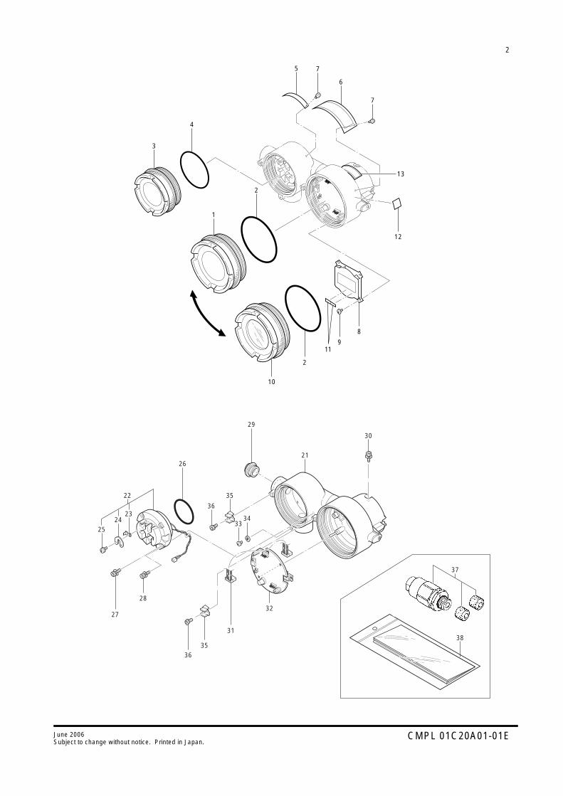
2
CMPL 01C20A01-01EJune 2006Subject to change without notice. Printed in Japan.
37
22 35
29
21
30
3433
36
38
26
2524
27
28
3635
31
32
23
1
3
2
4
5 7
6
7
2
8
13
12
911
10

3
CMPL 01C20A01-01EJune 2006Subject to change without notice. Printed in Japan.
CoverO-RingCoverO-RingTag No. Plate
Nameplate (Data Plate)Self-tapping Screw, M3×5LCD Board AssemblyB.H. Screw, M4×6Cover Assembly
Label (to be specified by user)Label (used for TIIS flameproof type and TIIS intrinsically safe type)Label (used only for TIIS intrinsically safe type)
12345
6789
10
111213
F9301DQG9303LKF9301DYG9303AMF9300NE
—F9300AGF9302DAY9406JBF9301MA
F9300PB——
11111
14121
211
Item Part No. DescriptionQty
For with Field Indicator*
Note *: In case of horizontal piping connection type, combination with field indicator is not available.
Case AssemblyTerminal Board Assembly
For General Use Type and Flameproof Type. (without lighting protector)For General Use Type and Flameproof Type. (with lighting protector)For Intrinsically Safe Type (without lightning protector)
For Intrinsically Safe Type (with lightning protector)HookJumperScrew
O-Ring
Hex Soc. H. Cap Screw with Spring WasherPan H. Screw, M4×18 with Spring Washer
PlugFor Electrical Connection Code: 5 (G1/2)For Electrical Connection Code: 6 (G3/4)
For Electrical Connection Code: 7 (1/2NPT)Hex. Soc. H. Cap Screw with Spring WasherCable AssemblyCPU Board Assembly
For General Use Type and Flameproof Type.
(without output selection switch for CPU fault)For General Use Type and Flameproof Type.
(with output selection switch for CPU fault, Option Code: /C1)For Intrinsically Safe Type
(without output selection switch for CPU fault)
Pan H. Screw, M4×6Lock WasherClampHex Soc. H. Cap ScrewCable Gland Assembly
Card
2122
23242526
272829
303132
3334353637
38
See Table 1Below
F9301FSF9301FYF9301FC
F9301FQF9301FFF9203CRF9270SJF9301FG
F9300AMY9418JH
BelowG9330DPG9330DQ
G9612ECF9300AHF9302KA
BelowF9302BA
F9302BC
F9302BS
F9340ALY9401WLG9339AAY9408ZUSee Table 2
G9339AB
11
3141
41
211
1122—
1
11
3141
411
211
1122—
1
Item Part No. Description
Qty
Typ
e
For Attached Flameproof Packing adapter (Option Code: /G)
For TIIS Flameproof Type
With
out C
onne
ctio
nfo
r R
emot
e In
dica
tor
With
Con
nect
ion
for
Rem
ote
Indi
cato
r
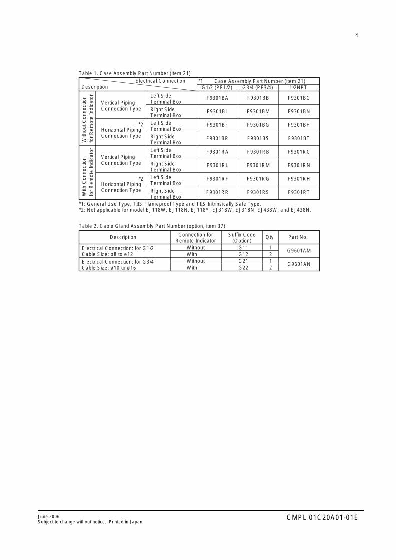
4
CMPL 01C20A01-01EJune 2006Subject to change without notice. Printed in Japan.
Table 1. Case Assembly Part Number (item 21)
*1: General Use Type, TIIS Flameproof Type and TIIS Intrinsically Safe Type.*2: Not applicable for model EJ118W, EJ118N, EJ118Y, EJ318W, EJ318N, EJ438W, and EJ438N.
*1
*2
*2
Case Assembly Part Number (item 21)G1/2 (PF1/2) G3/4 (PF3/4) 1/2NPT
Electrical ConnectionDescription
Description Qty Part No.
With
out C
onne
ctio
nfo
r R
emot
e In
dica
tor
With
Con
nect
ion
for
Rem
ote
Indi
cato
r
Vertical PipingConnection Type
Left SideTerminal Box
Connection forRemote Indicator
Suffix Code(Option)
Right SideTerminal BoxLeft SideTerminal BoxRight SideTerminal BoxLeft SideTerminal BoxRight SideTerminal BoxLeft SideTerminal BoxRight SideTerminal Box
Horizontal PipingConnection Type
Vertical PipingConnection Type
Horizontal PipingConnection Type
Electrical Connection: for G1/2Cable Size: ø8 to ø12
Without G11 1With G12 2Without G21 1With G22 2
Electrical Connection: for G3/4Cable Size: ø10 to ø16
F9301BA
F9301BL
F9301BF
F9301BR
F9301RA
F9301RL
F9301RF
F9301RR
F9301BB
F9301BM
F9301BG
F9301BS
F9301RB
F9301RM
F9301RG
F9301RS
F9301BC
F9301BN
F9301BH
F9301BT
F9301RC
F9301RN
F9301RH
F9301RT
G9601AM
G9601AN
Table 2. Cable Gland Assembly Part Number (option, item 37)
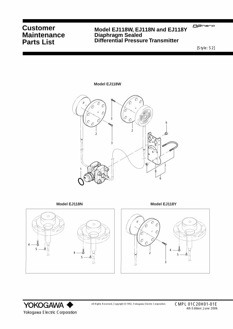
CustomerMaintenanceParts List
All Rights Reserved, Copyright © 1992, Yokogawa Electric Corporation.
Yokogawa Electric Corporation
CMPL 01C20H01-01E4th Edition: June 2006
Model EJ118W, EJ118N and EJ118YDiaphragm SealedDifferential Pressure Transmitter
4
5
4
54
5
8
6
7
22
3
3
2
3
9
1
Model EJ118W
Model EJ118N Model EJ118Y
[Style: S2]

2
CMPL 01C20H01-01EJune 2006Subject to change without notice. Printed in Japan.
O-RingFlange [see table 1]Screw [see table 1]Screw
For JIS10K
For JIS20K and ANSI Class 150For ANSI Class 300
Pan H. Screw, M612Bracket Assembly
SECC Carbon Steel
SUS304 Stainless SteelU-Bolt/Nut Assembly, SUS 304 Stainless SteelBracket
SECC Carbon SteelSUS 304 Stainless Steel
BoltS25C Carbon SteelSUS XM7 Stainless Steel
1234
56
78
9
F9300AJ——
BelowF9149WR
F9149WSF9149WTY9612HU
BelowF9270AW
F9300TAD0117XL-A
BelowF9270AXF9300TE
BelowF9270AYF9273CZ
124
1
11
4
1
8
81
11
4
Item Part No. Description
Qty
Mod
el
EJ1
18W
EJ1
18N
1124
41
11
4
EJ1
18Y
T01.EPS
Table 1. Flange and Screw Part Number (Item 2 and 3).
Pan H.Screw(item 3)
S25C Carbon Steel,80mm(3inch)
SUS304 Stainless Steel, 80mm(3inch)
Flange Rating
T02.EPS
Y9525ZU
Y9530ZU
Y9540ZU
Y9530ZU
Y9347VX
Y9540ZU
JIS 10K
JIS 20K
JIS 40K
ANSI Class 150
ANSI Class 300
ANSI Class 600
F9351KA
F9351KB
F9351KC
F9351KE
F9351KF
F9351KG
F9351GA
F9351GB
F9351GC
F9351GE
F9351GF
F9149LR

IM 01C20H01-01E
REVISION RECORDTitle: Model EJ118W, EJ118N, and EJ118Y Diaphragm Sealed Differential Pres-
sure TransmitterManual No.: IM 01C20H01-01E
Edition Date Page Revised Item
7th Oct. 2000 -
10-1
CMPL
Revised a book in a new format. (The location of contents and the associated page numbers may not coincide with the one in old editions.) • Add Chapter 10, General SpecificationsCMPL 1C20H1-01E 1st 2nd • Add Revision Record
REVISION RECORD.EPS
8th May 2002 -2-1
2-3 2-5
10-1CMPL
New coding system applied. • Delete CE marking from Figure 2.2. • Add "Confirming the certification mark." • Delete EMC Conformity number and the note for wire selection. • Delete CE marking and CE EMC Conformity number. CMPL 1C20A1-01E 2nd 01C20A01-01E 3rd • Add Part No. to item 5, Tag No. Plate (F9300NE).CMPL 1C20H1-01E 2nd 01C20H01-01E 3rd
9th June 2006 1-12-42-52-57-9
7-1610-5
-CMPL
1 • Revise layout of chapter 1 2.9.3 • Delete SAA Intrinsically safe type 2.10.2 • Add Caution of selecting cables 2.11 • Correct C-tick number 7.3.2 (5) • Add an example of low cut mode setting 7.3.2 (17) • Correct the definition of 'h' 10.3 • Delete option code /EF1 • JIS Certification TIIS Certification CMPL 01C20A01-01E 3rd 5th • Item22 F9301FT F9301FY • Item27, 28 Item27 Y9516ZU F9300AM Y9500SU Delete • Item29, 30 Item28 Y9418JB Y9418JH Y9400SP Delete • Item35 Item33 Y9406JU F9340AL • Item39, 41, 42 Delete parts • Item43 Item38 F9301FS G9339ABCMPL 01C20H01-01E 3rd 4th • Item9 F9270AX F9270AY F9300TE F9273CZ • Revise Table 1