
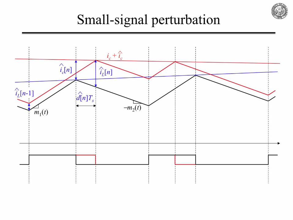
The Ideal Current ControllerThe ideal current controller causes the average inductor current to follow the control input:
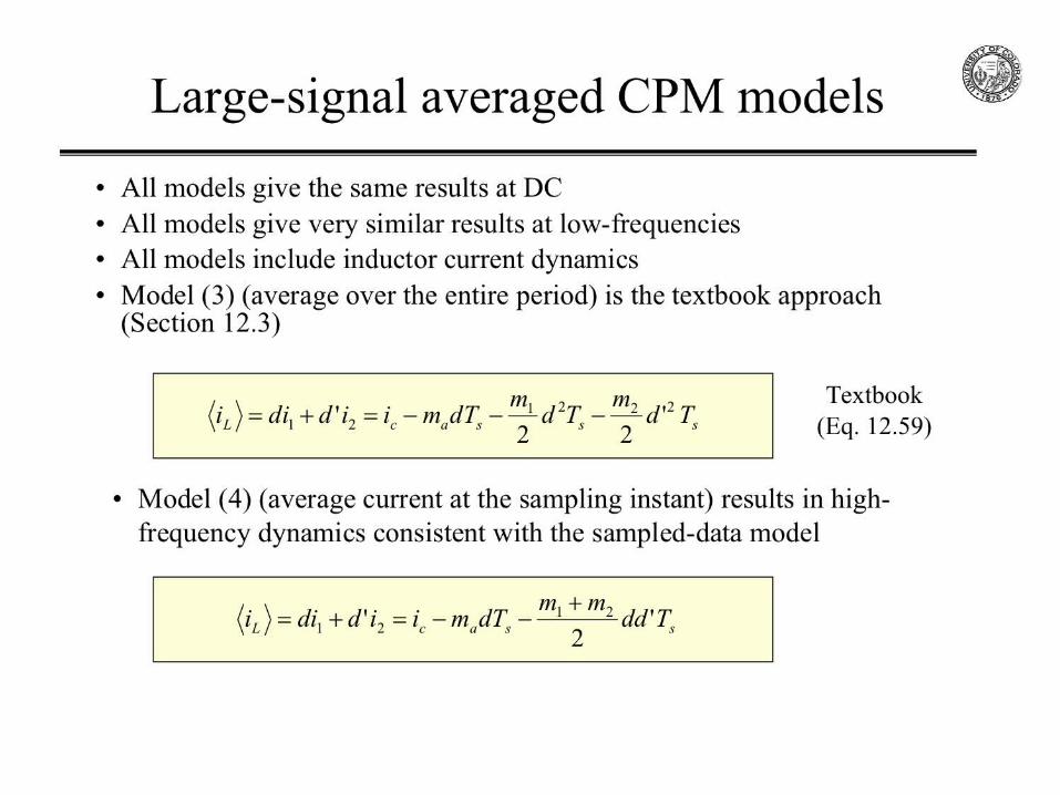
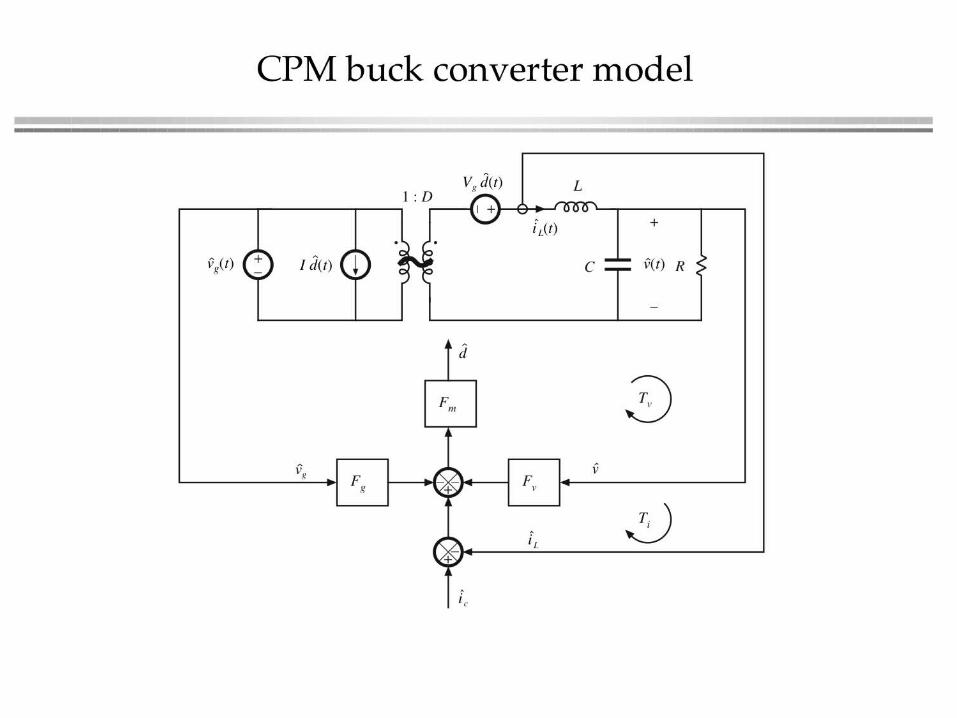
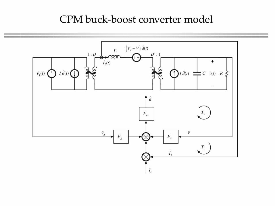
Large-signal and small-signal averaged switch models, buck example:


High-frequency pole(from the accurate averaged model (4))

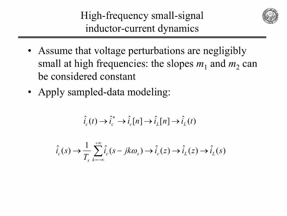
Compare to first-order approximation of the sampled-data control-to-current model
hfs
s
sT
sTc
L
sssT
e
esi
si s
s
ωπωααα
α
+=
−++
≈−
−−
=−
−
1
1
)/(111
11 1
1)(ˆ)(ˆ
)/(1
)/(1
πω
πω
s
ssT
s
s
e s
+
−≈−
ππαα s
a
shf
f
mm
DD
ff
2
221
1
1
1
+−=
+
−=
Control-to-inductor current response behaves approximately as a single-pole transfer function with a high-frequency pole at
Model (4) is consistent with the sampled-data small-signal model


DC gain of line-to-output Gvg-cpm(based on model (4))

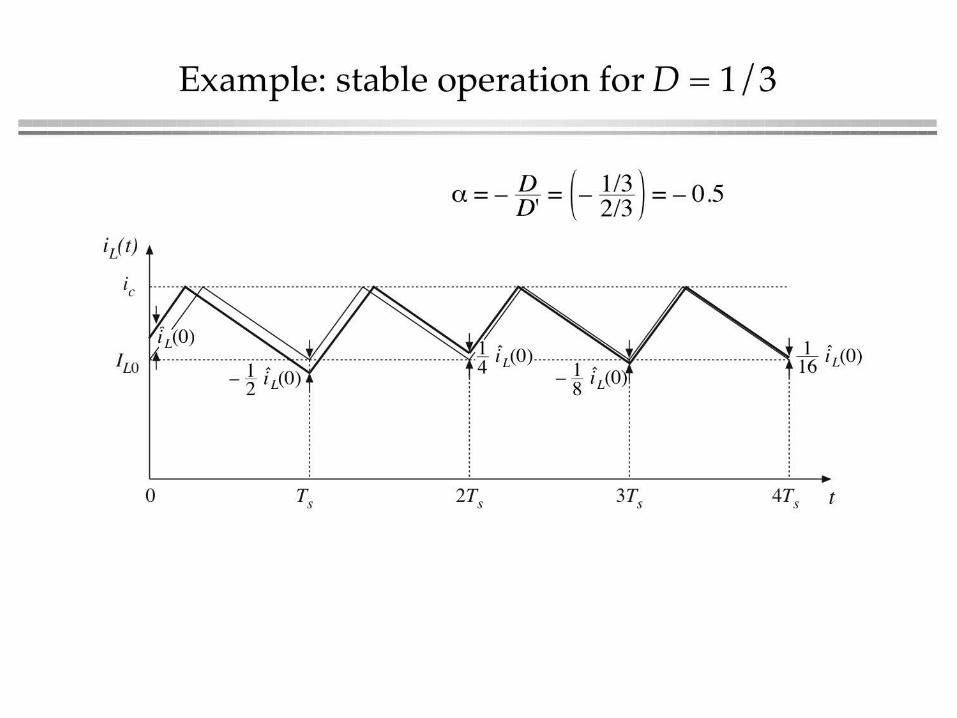
Example
• CPM buck converter: Vg = 10V, L = 5 H, C = 75 F, D = 0.5, V = 5 V,
I = 20 A, R = V/I = 0.25 , fs = 100 kHz
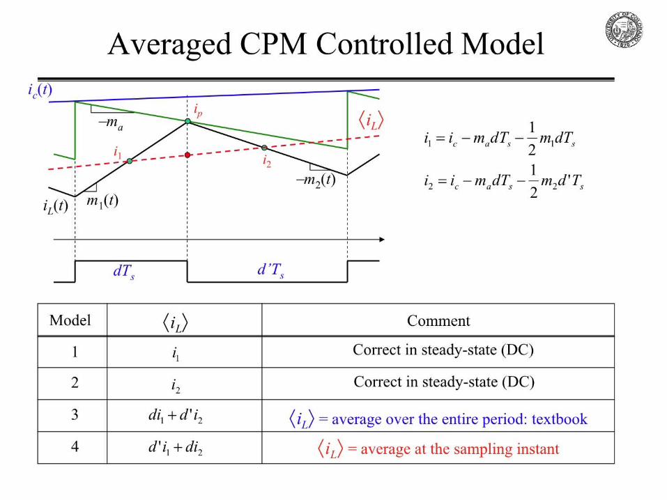
• Inductor current slopes:m1 = (Vg – V)/L = 1 A/s
m2 = V/L = 1 A/sD = 0.5: CPM controller is stable for any compensation ramp, ma/m2 > 0
Select: ma/m2 = Ma/M2 = 1, Ma = 1 A/s
A/V 25.02
'==
LTDD
F sg
1/A 1.01
2
1
21
=−+
=s
a
m TMMMF

Example (cont.)
kHz 2.81
2
1==
LCfo π
1==LC
RQ
47.047.01
1==
+
+= Q
LVRCFRVF
QQgm
gm
ckHz 3.1851 ==+= ogm
oc fRVF
ff
kHz 4.81 =≈ ccp fQf
kHz 39/2 =≈= cchfp Qfff
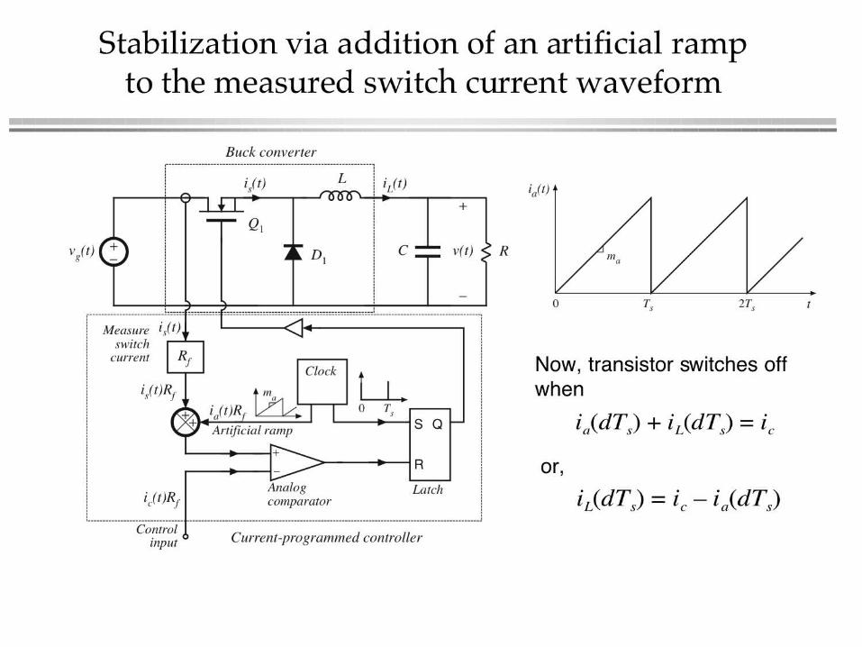
Duty-cycle control
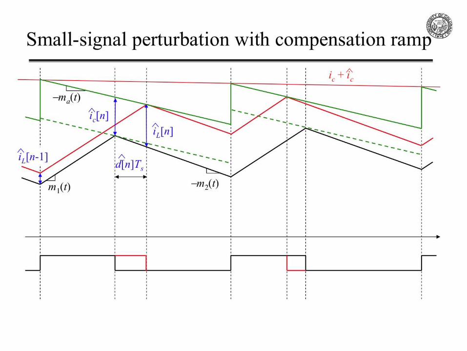
Peak current-mode control (CPM)
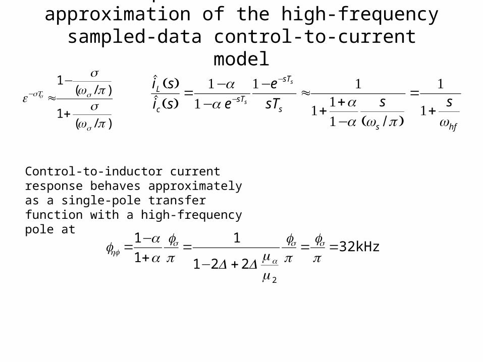
Compare to first-order approximation of the high-frequency sampled-data control-to-current model
hfs
s
sT
sTc
L
sssT
e
esi
si s
s
ωπωααα
α
+=
−++
≈−
−−
=−
−
1
1
)/(111
11 1
1)(ˆ)(ˆ
)/(1
)/(1
πω
πω
s
ssT
s
s
e s
+
−≈−
kHz 32221
1
1
1
2
==+−
=+−
=πππα
α ss
a
shf
ff
mm
DD
ff
Control-to-inductor current response behaves approximately as a single-pole transfer function with a high-frequency pole at

2nd-order approximation in the small-signal averaged model

2nd-order approximation in the small-signal averaged model


![PI CONTROLLER BASED SHUNT CONNECTED THREE ...realize the potential and feasibility of PI controller [17], [18]. (a) Current Wave of Current Controller (b) Current Controller Waveform](https://cdn.vdocuments.us/doc/165x107/604b4b4b953f6a233834072a/pi-controller-based-shunt-connected-three-realize-the-potential-and-feasibility.jpg)
