
___________________
___________________
___________________
___________________
___________________
___________________
___________________
___________________
SIMATIC
ET 200SP Technology Module TM Count 1x24V (6ES7138-6AA00-0BA0)
Manual
02/2017 A5E33002339-AB
Preface
Documentation guide 1
Product overview 2
Wiring 3
Configuring/address space 4
Interrupts/diagnostic messages
5
Technical specifications 6
Parameter data record A

Siemens AG Division Digital Factory Postfach 48 48 90026 NÜRNBERG GERMANY
A5E33002339-AB Ⓟ 02/2017 Subject to change
Copyright © Siemens AG 2017. All rights reserved
Legal information Warning notice system
This manual contains notices you have to observe in order to ensure your personal safety, as well as to prevent damage to property. The notices referring to your personal safety are highlighted in the manual by a safety alert symbol, notices referring only to property damage have no safety alert symbol. These notices shown below are graded according to the degree of danger.
DANGER indicates that death or severe personal injury will result if proper precautions are not taken.
WARNING indicates that death or severe personal injury may result if proper precautions are not taken.
CAUTION indicates that minor personal injury can result if proper precautions are not taken.
NOTICE indicates that property damage can result if proper precautions are not taken.
If more than one degree of danger is present, the warning notice representing the highest degree of danger will be used. A notice warning of injury to persons with a safety alert symbol may also include a warning relating to property damage.
Qualified Personnel The product/system described in this documentation may be operated only by personnel qualified for the specific task in accordance with the relevant documentation, in particular its warning notices and safety instructions. Qualified personnel are those who, based on their training and experience, are capable of identifying risks and avoiding potential hazards when working with these products/systems.
Proper use of Siemens products Note the following:
WARNING Siemens products may only be used for the applications described in the catalog and in the relevant technical documentation. If products and components from other manufacturers are used, these must be recommended or approved by Siemens. Proper transport, storage, installation, assembly, commissioning, operation and maintenance are required to ensure that the products operate safely and without any problems. The permissible ambient conditions must be complied with. The information in the relevant documentation must be observed.
Trademarks All names identified by ® are registered trademarks of Siemens AG. The remaining trademarks in this publication may be trademarks whose use by third parties for their own purposes could violate the rights of the owner.
Disclaimer of Liability We have reviewed the contents of this publication to ensure consistency with the hardware and software described. Since variance cannot be precluded entirely, we cannot guarantee full consistency. However, the information in this publication is reviewed regularly and any necessary corrections are included in subsequent editions.
Technology Module TM Count 1x24V (6ES7138-6AA00-0BA0) 4 Manual, 02/2017, A5E33002339-AB
Preface
Purpose of the documentation This manual includes module-specific information on wiring, diagnostics and the technical specifications of the technology module.
General information regarding design and commissioning of the ET 200SP is available in the ET 200SP system manual.
The counting and measuring functions of the TM Count 1x24V technology module are described in more detail in the Counting, Measurement and Position Detection (http://support.automation.siemens.com/WW/view/en/59709820) function manual.
Conventions Please observe notes marked as follows:
Note
A note contains important information on the product described in the documentation, on the handling of the product and on the section of the documentation to which particular attention should be paid.
Security information Siemens provides products and solutions with industrial security functions that support the secure operation of plants, systems, machines and networks.
In order to protect plants, systems, machines and networks against cyber threats, it is necessary to implement – and continuously maintain – a holistic, state-of-the-art industrial security concept. Siemens’ products and solutions only form one element of such a concept.
Customer is responsible to prevent unauthorized access to its plants, systems, machines and networks. Systems, machines and components should only be connected to the enterprise network or the internet if and to the extent necessary and with appropriate security measures (e.g. use of firewalls and network segmentation) in place.
Additionally, Siemens’ guidance on appropriate security measures should be taken into account. For more information about industrial security, please visit (http://www.siemens.com/industrialsecurity).
Siemens’ products and solutions undergo continuous development to make them more secure. Siemens strongly recommends to apply product updates as soon as available and to always use the latest product versions. Use of product versions that are no longer supported, and failure to apply latest updates may increase customer’s exposure to cyber threats.
To stay informed about product updates, subscribe to the Siemens Industrial Security RSS Feed under (http://www.siemens.com/industrialsecurity).
Preface
Technology Module TM Count 1x24V (6ES7138-6AA00-0BA0) Manual, 02/2017, A5E33002339-AB 5
Open Source Software Open-source software is used in the firmware of the product described. Open Source Software is provided free of charge. We are liable for the product described, including the open-source software contained in it, pursuant to the conditions applicable to the product. Siemens accepts no liability for the use of the open source software over and above the intended program sequence, or for any faults caused by modifications to the software.
For legal reasons, we are obliged to publish the original text of the license conditions and copyright notices. Please read the information on this on the Internet (https://support.industry.siemens.com/cs/ww/en/view/109740777).

Technology Module TM Count 1x24V (6ES7138-6AA00-0BA0) 6 Manual, 02/2017, A5E33002339-AB
Table of contents Preface ...................................................................................................................................................... 4
1 Documentation guide ................................................................................................................................. 7
2 Product overview ..................................................................................................................................... 11
2.1 Properties ............................................................................................................................... 11
2.2 Functions ................................................................................................................................ 14 2.2.1 Detection of counting signals ................................................................................................. 14 2.2.2 Measured value determination ............................................................................................... 16 2.2.3 Switching the outputs at comparison values .......................................................................... 17 2.2.4 Position input for Motion Control ............................................................................................ 17 2.2.5 Fast Mode .............................................................................................................................. 18 2.2.6 Additional functions ................................................................................................................ 20
3 Wiring ...................................................................................................................................................... 22
3.1 Pin assignment ....................................................................................................................... 22
4 Configuring/address space ...................................................................................................................... 28
4.1 Configuring ............................................................................................................................. 28
4.2 Reaction to CPU STOP ......................................................................................................... 31
4.3 Address space ....................................................................................................................... 32
4.4 Parameters ............................................................................................................................. 33 4.4.1 Parameter setting ................................................................................................................... 33 4.4.2 Parameters for operating with technology object "Counting and measurement" .................. 36 4.4.3 Parameters for position input for "Motion Control" technology object ................................... 41 4.4.4 Parameters for manual operation (without technology object) .............................................. 43 4.4.5 Parameters for operating in Fast Mode ................................................................................. 48
4.5 Control and feedback interface .............................................................................................. 52 4.5.1 Assignment of the control interface........................................................................................ 53 4.5.2 Assignment of the feedback interface .................................................................................... 55 4.5.3 Assignment of the feedback interface in Fast Mode .............................................................. 56
5 Interrupts/diagnostic messages ............................................................................................................... 57
5.1 Status and error displays ....................................................................................................... 57
5.2 Diagnostic messages ............................................................................................................. 60
5.3 Hardware interrupts ............................................................................................................... 64
6 Technical specifications ........................................................................................................................... 66
A Parameter data record ............................................................................................................................. 73
A.1 Parameter assignment and structure of the parameter data record ...................................... 73
A.2 Parameter validation error ..................................................................................................... 81

Technology Module TM Count 1x24V (6ES7138-6AA00-0BA0) 7 Manual, 02/2017, A5E33002339-AB
Documentation guide 1
The documentation for the SIMATIC ET 200SP distributed I/O system is arranged into three areas. This arrangement enables you to access the specific content you require.
Basic information
The system manual describes in detail the configuration, installation, wiring and commissioning of the SIMATIC ET 200SP. distributed I/O system. The STEP 7 online help supports you in the configuration and programming.
Device information
Product manuals contain a compact description of the module-specific information, such as properties, wiring diagrams, characteristics and technical specifications.

Documentation guide
Technology Module TM Count 1x24V (6ES7138-6AA00-0BA0) 8 Manual, 02/2017, A5E33002339-AB
General information
The function manuals contain detailed descriptions on general topics regarding the SIMATIC ET 200SP distributed I/O system, e.g. diagnostics, communication, Web server, motion control and OPC UA.
You can download the documentation free of charge from the Internet (http://w3.siemens.com/mcms/industrial-automation-systems-simatic/en/manual-overview/tech-doc-et200/Pages/Default.aspx).
Changes and supplements to the manuals are documented in a Product Information.
You can download the product information free of charge from the Internet (https://support.industry.siemens.com/cs/us/en/view/73021864).
Manual Collection ET 200SP The Manual Collection contains the complete documentation on the SIMATIC ET 200SP distributed I/O system gathered together in one file.
You can find the Manual Collection on the Internet (https://support.industry.siemens.com/cs/ww/en/view/84133942).
"mySupport" With "mySupport", your personal workspace, you make the most of your Industry Online Support.
In "mySupport" you can store filters, favorites and tags, request CAx data and put together your personal library in the Documentation area. Furthermore, your data is automatically filled into support requests and you always have an overview of your current requests.
You need to register once to use the full functionality of "mySupport".
You can find "mySupport" in the Internet (https://support.industry.siemens.com/My/ww/en).
"mySupport" - Documentation In the Documentation area of "mySupport", you have the possibility to combine complete manuals or parts of them to make your own manual. You can export the manual in PDF format or in an editable format.
You can find "mySupport" - Documentation in the Internet (http://support.industry.siemens.com/My/ww/en/documentation).

Documentation guide
Technology Module TM Count 1x24V (6ES7138-6AA00-0BA0) Manual, 02/2017, A5E33002339-AB 9
"mySupport" - CAx Data In the CAx Data area of "mySupport", you can have access the latest product data for your CAx or CAe system.
You configure your own download package with a few clicks.
In doing so you can select:
● Product images, 2D dimension drawings, 3D models, internal circuit diagrams, EPLAN macro files
● Manuals, characteristics, operating manuals, certificates
● Product master data
You can find "mySupport" - CAx Data in the Internet (http://support.industry.siemens.com/my/ww/en/CAxOnline).
Application examples The application examples support you with various tools and examples for solving your automation tasks. Solutions are shown in interplay with multiple components in the system - separated from the focus in individual products.
You can find the application examples on the Internet (https://support.industry.siemens.com/sc/ww/en/sc/2054).
TIA Selection Tool With the TIA Selection Tool, you can select, configure and order devices for Totally Integrated Automation (TIA). This tool is the successor of the SIMATIC Selection Tool and combines the known configurators for automation technology into one tool. With the TIA Selection Tool, you can generate a complete order list from your product selection or product configuration.
You can find the TIA Selection Tool on the Internet (http://w3.siemens.com/mcms/topics/en/simatic/tia-selection-tool).

Documentation guide
Technology Module TM Count 1x24V (6ES7138-6AA00-0BA0) 10 Manual, 02/2017, A5E33002339-AB
SIMATIC Automation Tool You can use the SIMATIC Automation Tool to run commissioning and maintenance activities simultaneously on various SIMATIC S7 stations as a bulk operation independently of the TIA Portal.
The SIMATIC Automation Tool provides a multitude of functions:
● Scanning of a PROFINET/Ethernet network and identification of all connected CPUs
● Address assignment (IP, subnet, gateway) and station name (PROFINET device) to a CPU
● Transfer of the data and the programming device/PC time converted to UTC time to the module
● Program download to CPU
● Operating mode switchover RUN/STOP
● Localization of the CPU by means of LED flashing
● Reading out CPU error information
● Reading the CPU diagnostic buffer
● Reset to factory settings
● Updating the firmware of the CPU and connected modules
You can find the SIMATIC Automation Tool on the Internet (https://support.industry.siemens.com/cs/ww/en/view/98161300).
PRONETA With SIEMENS PRONETA (PROFINET network analysis), you analyze the plant network during commissioning. PRONETA features two core functions:
● The topology overview independently scans PROFINET and all connected components.
● The IO check is a fast test of the wiring and the module configuration of a system.
You can find SIEMENS PRONETA on the Internet (https://support.industry.siemens.com/cs/ww/en/view/67460624).

Technology Module TM Count 1x24V (6ES7138-6AA00-0BA0) 11 Manual, 02/2017, A5E33002339-AB
Product overview 2 2.1 Properties
Article number 6ES7138-6AA00-0BA0
View of the module
① Module type and designa-
tion ⑥ LED for encoder supply
② LED for diagnostics ⑦ LED for supply voltage ③ 2D matrix code ⑧ Function class ④ Terminal connection dia-
gram ⑨ Module type color coding
⑤ LEDs for channel status ⑩ Article number
Figure 2-1 View of the TM Count 1x24V module

Product overview 2.1 Properties
Technology Module TM Count 1x24V (6ES7138-6AA00-0BA0) 12 Manual, 02/2017, A5E33002339-AB
Properties The TM Count 1x24V technology module has the following properties:
● Technical properties
– One channel
– Interfaces:
24 V encoder signals A, B and N from sourcing, sinking or push pull encoders and sensors
24 V encoder supply output, short-circuit proof
DI0, DI1 and DI2 digital input signals
DQ0 and DQ1 digital output signals
L+ supply voltage
– Count range: 32 bits
– Fast Mode configurable
– Monitoring of encoder signals for wire break
– Hardware interrupts configurable
– Input filters for suppression of interferences at encoder inputs and digital inputs can be configured
● Supported encoder/signal types
– 24 V incremental encoder with and without N signal
– 24 V pulse encoder with direction signal
– 24 V pulse encoder without direction signal
– 24 V pulse encoders for up & down pulses
● Supported system functions
– Isochronous mode
– Firmware Update
– Identification data I&M

Product overview 2.1 Properties
Technology Module TM Count 1x24V (6ES7138-6AA00-0BA0) Manual, 02/2017, A5E33002339-AB 13
The module supports the following functions:
Table 2- 1 Version dependencies of module functions
Function Firmware version of
the module
Configurable as of STEP 7
(TIA Portal) STEP 7 GSD
PROFINET IO
PROFIBUS DP
Counting/measuring V1.0 or higher
V13 V5.5 SP4 or V5.5
SP3 with HSP0240
V1.0
X X
Operating with technology ob-ject "Counting and measure-ment"
V1.0 or higher
V13 — — —
Position input for technology object "Motion Control"
V1.0 or higher
V13 — — —
Centralized operation on CPU 151xSP
V1.1 or higher
V13 SP1 — — —
Fast Mode V1.2 or higher
V14 SP1 or V14 with HSP0199
V5.6 or V5.5
SP4 with HSP0240
V5.0
X X
Accessories The following accessories can be used with the module and are not included in the scope of delivery:
● Labeling strip
● Color identification labels
● Reference identification labels
● Shield connector
A BaseUnit of the A0 type is required to operate the technology module. For an overview of the BaseUnits that you can use with the technology module, please refer to the product information on the documentation for the ET 200SP Distributed I/O System (http://support.automation.siemens.com/WW/view/en/73021864).
For detailed information on the installation procedure, refer to the ET 200SP Distributed I/O System (http://support.automation.siemens.com/WW/view/en/58649293) system manual.
Product overview 2.2 Functions
Technology Module TM Count 1x24V (6ES7138-6AA00-0BA0) 14 Manual, 02/2017, A5E33002339-AB
2.2 Functions
2.2.1 Detection of counting signals Counting refers to the detection and summation of events. The counters of the technology module detect encoder signals and pulses and evaluate them accordingly. The count direction can be specified using encoder or pulse signals or through the user program.
You can control the counting processes with the digital inputs.
You can specify the counter characteristics using the functions described below.
Counting limits The counting limits define the counter value range used. The counting limits are configurable and can be modified during runtime with the user program.
The maximum possible counting limit is 2147483647 (231–1). The minimum possible counting limit is –2147483648 (–231).
You can configure the response of the counter at the counting limits:
● Continue or stop counting upon violation of a counting limit (automatic gate stop)
● Set counter value to start value or to other counting limit upon violation of a counting limit
Start value You can configure a start value within the counting limits. The start value can be modified during runtime with the user program.
Depending on the parameter assignment, the technology module can set the current counter value to the start value upon synchronization, upon Capture function activation, upon violation of a counting limit or when the gate is opened.
Gate control Opening and closing the hardware gate and software gate defines the period of time during which the counting signals are captured.
The control of the hardware gate takes place externally via the digital inputs of the technology module. Control of the software gate takes place via the user program. The hardware gate can be enabled through parameter assignment. The software gate (bit in the control interface (Page 53) of the cyclic I/O data) cannot be deactivated.
Product overview 2.2 Functions
Technology Module TM Count 1x24V (6ES7138-6AA00-0BA0) Manual, 02/2017, A5E33002339-AB 15
Capture (Latch) You can configure an external reference signal edge that triggers the saving of the current counter value as Capture value. The following external signals can trigger the Capture function:
● Rising or falling edge of a digital input
● Both edges of a digital input
● Rising edge of the N signal at the encoder input
When using a digital input, you can specify whether counting is to continue from the current counter value or from the start value after the Capture function. When the rising edge of the N signal at the encoder input is used, counting is to continue from the current counter value after the Capture function.
Hardware interrupts The technology module can trigger a hardware interrupt in the CPU, for example, if a comparison event occurs, in the event of overflow or underflow, in the event of a zero crossing of the counter and/or of a change of count direction (direction reversal). You can specify which events (Page 64) are to trigger a hardware interrupt during operation.

Product overview 2.2 Functions
Technology Module TM Count 1x24V (6ES7138-6AA00-0BA0) 16 Manual, 02/2017, A5E33002339-AB
2.2.2 Measured value determination The following measuring functions are available: Measurement type Description Frequency measurement The mean frequency is calculated at set measuring intervals on the
basis of the time profile of the count pulses and returned in hertz as the floating point number.
Period measurement The mean period duration is calculated at set measuring intervals on the basis of the time profile of the count pulses and returned in seconds as the floating point number.
Velocity measurement The mean velocity is calculated at set measuring intervals on the basis of the time profile of the count pulses and other parameters, and returned in the configured unit of measurement.
The measured value and the counter value are available concurrently in the feedback interface.
Update time You can configure the interval at which the technology module updates the measured values cyclically as the update time. Setting longer update time intervals allows uneven measured variables to be smoothed and increases measuring accuracy.
Gate control Opening and closing the hardware gate and software gate defines the period of time during which the counting signals are captured. The update time is asynchronous to the opening of the gate, which means that the update time is not started when the gate is opened. After closing, the last measured value captured continues to be returned.
Measuring ranges The measuring functions have the following measuring range limits: Measurement type Low measuring range limit High measuring range limit Frequency measurement 0.04 Hz 800 kHz* Period measurement 1.25 µs* 25 s Velocity measurement Depends on the configured number of "increments per unit" and the
"time base for velocity measurement" * Applies to 24 V incremental encoders and "quadruple" signal evaluation.
All measured values are returned as signed values. The sign indicates whether the counter value increased or decreased during the relevant time period.

Product overview 2.2 Functions
Technology Module TM Count 1x24V (6ES7138-6AA00-0BA0) Manual, 02/2017, A5E33002339-AB 17
2.2.3 Switching the outputs at comparison values You define two comparison values that can control the two digital outputs independent of the user program. The comparison values are configurable and can be modified during runtime with the user program.
Comparison values in the Counting mode You define two comparison values in the Counting mode. If the current counter value meets the configured comparison condition, the corresponding digital output can be set to directly initiate control processes in the process.
Comparison values in the Measuring mode You define two comparison values in the Measuring mode. If the current measured value meets the configured comparison condition, the corresponding digital output can be set to directly initiate control processes in the process.
2.2.4 Position input for Motion Control You can use the technology module with an incremental encoder for position detection with S7-1500 Motion Control . Position detection is based on the counting function of the technology module which evaluates the captured encoder signals and sends them to the S7-1500 Motion Control.
The range of functions of the technology module has the following limitations in this case:
● Counter behavior not configurable
● No functions for digital inputs available
● No comparison functions for digital outputs available
● No hysteresis available
● No hardware interrupts available
In the device configuration of the technology module in STEP 7 (TIA Portal), select "Position input for technology object "Motion Control"".
Additional information A detailed description of the use of Motion Control and its configuration is available in the function manual S7-1500 Motion Control as a download from the Internet (http://support.automation.siemens.com/WW/view/en/59381279).
Product overview 2.2 Functions
Technology Module TM Count 1x24V (6ES7138-6AA00-0BA0) 18 Manual, 02/2017, A5E33002339-AB
2.2.5 Fast Mode You can use the technology module in Fast Mode for very fast detection of the counter value in case of compressed functionality. In Fast Mode, you have access to a reduced feedback interface but not to a control interface. This means you can use a shorter send clock for the CPU.
The range of functions of the technology module has the following additional limitations in Fast Mode:
● Parameter change in RUN only possible with data record 128
● Count/position value range: 25 bits
● No measured value available
● No software gate available
● No Capture function available
● No hardware interrupts available
● Combined error message (feedback bit) that is acknowledged automatically
To do this, select "Fast Mode" operating mode in the device configuration of the technology module in STEP 7 (TIA Portal).
You can specify the behavior of the counter using the functions described below.
Counting limits The counting limits define the counter value range used. The counter limits are configurable and can be modified during runtime using data record 128 but not through the control interface.
The maximum possible counting limit is 33554431 (225–1). The minimum possible counting limit is 0.
You can configure the response of the counter at the counting limits:
● Continue or stop counting upon violation of a counting limit (automatic gate stop with configured hardware gate)
● Set counter value to start value or to other counting limit upon violation of a counting limit
Start value You can configure a start value within the counting limits. The start value can only be modified during runtime with data record 128.
Depending on the parameter assignment, the technology module can set the current counter value to the start value upon synchronization, upon violation of a counting limit or when the configured hardware gate is opened.

Product overview 2.2 Functions
Technology Module TM Count 1x24V (6ES7138-6AA00-0BA0) Manual, 02/2017, A5E33002339-AB 19
Gate control Opening and closing the hardware gate (HW gate) defines the period of time during which the counting signals are recorded.
The control of the hardware gate takes place externally via the digital inputs of the technology module. The hardware gate can be enabled through parameter assignment. All count signal are recorded when you do not configure a hardware gate. A software gate is not available.

Product overview 2.2 Functions
Technology Module TM Count 1x24V (6ES7138-6AA00-0BA0) 20 Manual, 02/2017, A5E33002339-AB
2.2.6 Additional functions
Synchronization You can configure the edge of an external reference signal to load the counter with the specified start value. The following external signals can trigger a synchronization:
● Rising or falling edge of a digital input
● Rising edge of the N signal at the encoder input
● Rising edge of the N signal at the encoder input depending on the level of the assigned digital input
Hysteresis You can specify a hysteresis for the comparison values within which a digital output will be prevented from switching again. An encoder can come to a standstill at a specific position, and slight movements may make the counter value fluctuate around this position. If a comparison value or a counting limit lies within this fluctuation range, the corresponding digital output will be switched on and off with corresponding frequency if hysteresis is not used. The hysteresis prevents these unwanted switching operations.
Diagnostic interrupt The technology module can trigger a diagnostic interrupt in the event of a missing supply voltage or an error at the digital outputs, for example. You enable the diagnostic interrupts (Page 60) in the device configuration.
Input filter To suppress interference, you can configure an input filter for the 24 V encoder inputs and for the digital inputs.

Product overview 2.2 Functions
Technology Module TM Count 1x24V (6ES7138-6AA00-0BA0) Manual, 02/2017, A5E33002339-AB 21
Isochronous mode The technology module supports the "isochronous mode" system function in distributed operation. This system function enables counter values and measured values to be acquired in a defined system cycle.
In isochronous mode, the cycle of the user program, the transmission of the input signals and processing in the technology module are synchronized. The output signals switch immediately if the relevant comparison condition is met. A change in the state of a digital input immediately affects the planned reaction of the technology module and changes the status bit of the digital input in the feedback interface (Page 55).
Data processing
The data that was transmitted to the technology module in the current bus cycle via the control interface takes effect when it is processed in the internal technology module cycle. The counter value and the measured value as well as status bits are captured at time Ti and made available in the feedback interface for retrieval in the current bus cycle.
Additional information
A detailed description of isochronous mode can be found in the PROFINET with STEP 7 function manual, which is available for download on the Internet (https://support.industry.siemens.com/cs/ww/en/view/49948856).

Technology Module TM Count 1x24V (6ES7138-6AA00-0BA0) Manual, 02/2017, A5E33002339-AB 22
Wiring 3 3.1 Pin assignment
The TM Count 1x24V is used with a BaseUnit of the A0 type.
The encoder signals, the digital input and output signals and the encoder supply are connected to the BaseUnit of the technology module. The supply voltage feed on the light BaseUnit BU...D of the associated potential group supplies the module and the digital outputs, and generates the encoder supply voltage.
BaseUnit The BaseUnit is not included in the scope of delivery of the module and must be ordered separately.
For an overview of the BaseUnits to be used with the technology module, refer to the product information on the documentation for the ET 200SP Distributed I/O System (http://support.automation.siemens.com/WW/view/en/73021864).
You can find information about selecting a suitable BaseUnit in the ET 200SP Distributed I/O System (http://support.automation.siemens.com/WW/view/en/58649293) system manual and ET 200SP BaseUnits (http://support.automation.siemens.com/WW/view/en/58532597/133300) device manual.
You can find information on wiring the BaseUnit, connecting cable shields, etc. in the Connecting section of the ET 200SP Distributed I/O System (http://support.automation.siemens.com/WW/view/en/58649293) system manual.
Wiring 3.1 Pin assignment
Technology Module TM Count 1x24V (6ES7138-6AA00-0BA0) Manual, 02/2017, A5E33002339-AB 23
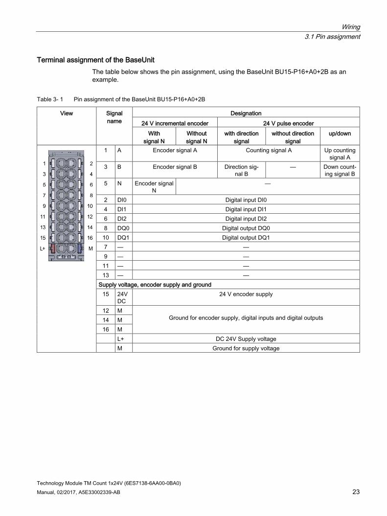
Terminal assignment of the BaseUnit The table below shows the pin assignment, using the BaseUnit BU15-P16+A0+2B as an example.
Table 3- 1 Pin assignment of the BaseUnit BU15-P16+A0+2B
View Signal name
Designation 24 V incremental encoder 24 V pulse encoder
With signal N
Without signal N
with direction signal
without direction signal
up/down
1 A Encoder signal A Counting signal A Up counting signal A
3 B Encoder signal B Direction sig-nal B
— Down count-ing signal B
5 N Encoder signal N
—
2 DI0 Digital input DI0 4 DI1 Digital input DI1 6 DI2 Digital input DI2 8 DQ0 Digital output DQ0
10 DQ1 Digital output DQ1 7 — — 9 — —
11 — — 13 — —
Supply voltage, encoder supply and ground 15 24V
DC 24 V encoder supply
12 M Ground for encoder supply, digital inputs and digital outputs 14 M
16 M L+ DC 24V Supply voltage M Ground for supply voltage
Wiring 3.1 Pin assignment
Technology Module TM Count 1x24V (6ES7138-6AA00-0BA0) 24 Manual, 02/2017, A5E33002339-AB
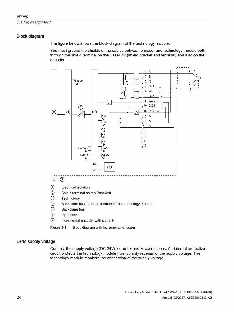
Block diagram The figure below shows the block diagram of the technology module.
You must ground the shields of the cables between encoder and technology module both through the shield terminal on the BaseUnit (shield bracket and terminal) and also on the encoder.
① Electrical isolation ② Shield terminal on the BaseUnit ③ Technology ④ Backplane bus interface module of the technology module ⑤ Backplane bus ⑥ Input filter ⑦ Incremental encoder with signal N
Figure 3-1 Block diagram with incremental encoder
L+/M supply voltage Connect the supply voltage (DC 24V) to the L+ and M connections. An internal protective circuit protects the technology module from polarity reversal of the supply voltage. The technology module monitors the connection of the supply voltage.

Wiring 3.1 Pin assignment
Technology Module TM Count 1x24V (6ES7138-6AA00-0BA0) Manual, 02/2017, A5E33002339-AB 25
24VDC encoder supply To supply the encoder and sensors at the digital inputs, the technology module supplies the DC 24V supply voltage at the 24VDC output with reference to M. Voltage is supplied from the L+/M supply voltage and monitored for short circuits and overload.
24 V encoder signals/count signals The 24 V encoder signals are designated A, B and N. You can connect the following encoder types:
● Incremental encoder with signal N:
The signals A, B and N are connected by means of the correspondingly labeled terminals. Signals A and B are the two incremental signals phase-shifted by 90°. N is the zero mark signal which returns one pulse per revolution.
● Incremental encoder without signal N:
The signals A and B are connected by means of the correspondingly labeled terminals. Signals A and B are the two incremental signals phase-shifted by 90°. The N terminal remains disconnected.
● Pulse encoders without direction signal:
The counting signal is connected to the A terminal. The count direction is specified via the control interface. The B and N terminals remain disconnected.
● Pulse encoders with direction signal:
The counting signal is connected to the A terminal. The direction signal is connected to the B terminal. The N terminal remains disconnected.
● Pulse encoders with counting signal up/down:
The up counting signal is connected to the A terminal. The down counting signal is connected to the B terminal. The N terminal remains disconnected.
The inputs are not electrically isolated from each other. The inputs are isolated against the backplane bus.
You can connect the following encoders or sensors at inputs A, B and N:
● Sourcing output: The inputs A, B and N are switched by the encoder or sensor after 24VDC .
● Sinking output: The inputs A, B and N are switched by the encoder or sensor after ground M .
● Push pull: The inputs A, B and N are switched by the encoder or sensor alternately after 24VDC and ground M . Monitoring for wire break is possible with this type of encoder/sensor. The wire break detection procedure (alternate switching) allows the counter value to change in the event of an error (wire break) even without count pulses until the wire break is detected.

Wiring 3.1 Pin assignment
Technology Module TM Count 1x24V (6ES7138-6AA00-0BA0) 26 Manual, 02/2017, A5E33002339-AB
Input filter for 24 V encoder signals To suppress interferences, you can configure an input filter for the counting inputs A, B and N. The selected filter frequency is based on a pulse/break ratio of between 40:60 and 60:40. This results in a specific minimum pulse/break time. Signal changes with a duration shorter than the minimum pulse/break time are suppressed.
You can specify the following values for the filter frequency:
Table 3- 2 Filter frequency and respective minimum pulse/break time
Filter frequency Minimum pulse/break time 100 Hz 4.0 ms 200 Hz 2.0 ms 500 Hz 800 µs 1 kHz 400 µs 2 kHz 200 µs 5 kHz 80 µs 10 kHz 40 µs 20 kHz 20 µs 50 kHz 8.0 µs 100 kHz 4.0 µs 200 kHz (default) 2.0 µs
Digital inputs DI0, DI1 and DI2 There are three digital inputs. The digital inputs are used for gate control, synchronization and the Capture function. Alternatively, you can use one or more digital inputs without the mentioned functions and read the signal state of the respective digital input via the feedback interface.
The digital inputs are not electrically isolated from each other.
Input delay for digital inputs This parameter can be used to suppress signal noise at the digital inputs of a channel. Changes to the signal are only detected if they remain stable for longer than the configured input delay time.
You can specify the following values for the input delay:
● None
● 0.05 ms
● 0.1 ms (default)
● 0.4 ms
● 0.8 ms
● 1.6 ms
● 3.2 ms

Wiring 3.1 Pin assignment
Technology Module TM Count 1x24V (6ES7138-6AA00-0BA0) Manual, 02/2017, A5E33002339-AB 27
● 12.8 ms
● 20 ms
Note
If you select the "None" or "0.05 ms" option, you have to use shielded cables for connection of the digital inputs.
Digital outputs DQ0 and DQ1 There are two digital outputs. The two digital outputs DQ0 and DQ1 can be activated/switched directly by the specified comparison values or by the user program.
The digital outputs are not isolated from each other.
The digital outputs are 24 V sourcing outputs in reference to M and can carry a rated load current of 0.5 A. They are protected from overload and short-circuit.
Note
Relays and contactors can be connected direct without external circuitry. You can find information on the maximum possible operating frequencies and the inductive loads at the digital outputs in the section Technical specifications (Page 66).

Technology Module TM Count 1x24V (6ES7138-6AA00-0BA0) Manual, 02/2017, A5E33002339-AB 28
Configuring/address space 4 4.1 Configuring
Introduction The technology module is configured and assigned parameters with the configuration software.
The technology module functions are controlled and monitored by the user program.
System environment The technology module can be used in the following system environments:
Applications Components required Configuration software In the user program Centralized opera-tion with a CPU 151xSP
• S7-1500 automation system
• TM Count 1x24V
STEP 7 (TIA Portal): Operating with technology object "Counting and measurement" • Device configuration with hardware
configuration • Parameter setting with
High_Speed_Counter technology object
High_Speed_Counter in-struction
STEP 7 (TIA Portal): Position input for technology object "Motion Control" • Device configuration with hardware
configuration • Parameter setting with axis tech-
nology object
Motion Control instructions
STEP 7 (TIA Portal): Manual operation (without technology object) • Device configuration and parameter
setting with hardware configuration
Direct access to the control and feedback interface (Page 52) in the I/O data
STEP 7 (TIA Portal): Fast Mode • Device configuration and parameter
setting with hardware configuration
Direct access to the feed-back interface (Page 56) in the I/O data

Configuring/address space 4.1 Configuring
Technology Module TM Count 1x24V (6ES7138-6AA00-0BA0) Manual, 02/2017, A5E33002339-AB 29
Applications Components required Configuration software In the user program Distributed operation with an S7-1500 CPU
• S7-1500 automation system
• ET 200SP distributed I/O system
• TM Count 1x24V
STEP 7 (TIA Portal): Operating with technology object "Counting and measurement" • Device configuration with hardware
configuration • Parameter setting with
High_Speed_Counter technology object
High_Speed_Counter in-struction
STEP 7 (TIA Portal): Position input for technology object "Motion Control" • Device configuration with hardware
configuration • Parameter setting with axis tech-
nology object
Motion Control instructions
STEP 7 (TIA Portal): Manual operation (without technology object) • Device configuration and parameter
setting with hardware configuration
Direct access to the control and feedback interface in the I/O data
STEP 7 (TIA Portal): Fast Mode • Device configuration and parameter
setting with hardware configuration
Direct access to the feed-back interface (Page 56) in the I/O data
Distributed operation with a CPU S7-300/400 or S7-1200
• S7-300/400 or S7-1200 automation system
• ET 200SP distributed I/O system
• TM Count 1x24V
STEP 7 (TIA Portal): Device configuration and parameter setting with hardware configuration STEP 7: Device configuration and parameter setting
Direct access to the control and feedback interface (Page 52) in the I/O data
Distributed operation in a third-party sys-tem
• Third-party automation system
• ET 200SP distributed I/O system
• TM Count 1x24V
Third-party configuration software: Device configuration and parameter settings with GSD file

Configuring/address space 4.1 Configuring
Technology Module TM Count 1x24V (6ES7138-6AA00-0BA0) 30 Manual, 02/2017, A5E33002339-AB
Additional information A detailed description of the counting and measuring functions and their configuration is available:
● In the Counting, Measurement and Position Detection function manual available for download on the Internet (http://support.automation.siemens.com/WW/view/en/59709820)
● In the STEP 7 (TIA Portal) information system under "Using technology functions > Counting, measurement and position input > Counting, measurement and position input (S7-1500)"
A detailed description of the use of Motion Control and its configuration is available:
● In the S7-1500 Motion Control function manual available as a download from the Internet (http://support.automation.siemens.com/WW/view/en/59381279)
● In the STEP 7 (TIA Portal) information system under "Using technology functions > Motion Control > Motion Control (S7-1200, S7-1500)"
Hardware Support Packages (HSP) STEP 7 (TIA Portal)
If the "Fast Mode" operating mode of the technology module is not yet integrated in the TIA Portal version you are using, you can integrate a corresponding module with HSP0199.
The Hardware Support Packages (HSP) are available for download on the Internet (https://support.industry.siemens.com/cs/ww/en/view/72341852).
Alternatively, they can be accessed for downloading via the menu bar of STEP 7 (TIA Portal): "Options > Support Packages > Download from the Internet".
STEP 7
The Hardware Support Packages (HSP) are available for download on the Internet (https://support.industry.siemens.com/cs/ww/en/view/23183356).
GSD file The respective GSD file for the ET 200SP distributed I/O system is available for download on the Internet:
● GSD file PROFINET IO (http://support.automation.siemens.com/WW/view/en/57138621)
● GSD file PROFIBUS DP (http://support.automation.siemens.com/WW/view/en/73016883)

Configuring/address space 4.2 Reaction to CPU STOP
Technology Module TM Count 1x24V (6ES7138-6AA00-0BA0) Manual, 02/2017, A5E33002339-AB 31
4.2 Reaction to CPU STOP You set the response of the technology module to CPU STOP for each channel in the basic parameters of the device configuration.
Table 4- 1 Response of technology module to CPU STOP
Option Meaning Continue opera-tion
The technology module remains fully functional. Incoming count pulses are pro-cessed. The digital outputs continue to switch according to the parameter as-signment.
Output substitute value
The technology module outputs the configured substitute values at the digital outputs until the next CPU STOP-RUN transition. The technology module is returned to its startup state after a STOP-RUN transi-tion: The counter value is set to the start value and the digital outputs switch according to the parameter assignment.
Keep last value The technology module outputs the values at the digital outputs that were valid when the transition to STOP took place until the next CPU STOP-RUN transition. If a digital output with the function "At comparison value for a pulse duration" is set at CPU stop, the digital output is reset after the pulse duration elapses. The technology module is returned to its startup state after a STOP-RUN transi-tion: The counter value is set to the start value and the digital outputs switch according to the parameter assignment.
Configuring/address space 4.3 Address space
Technology Module TM Count 1x24V (6ES7138-6AA00-0BA0) 32 Manual, 02/2017, A5E33002339-AB
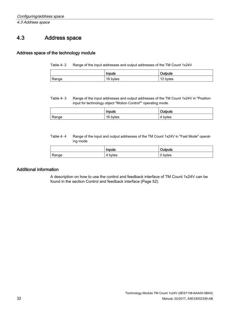
4.3 Address space
Address space of the technology module
Table 4- 2 Range of the input addresses and output addresses of the TM Count 1x24V
Inputs Outputs Range 16 bytes 12 bytes
Table 4- 3 Range of the input addresses and output addresses of the TM Count 1x24V in "Position input for technology object "Motion Control"" operating mode.
Inputs Outputs Range 16 bytes 4 bytes
Table 4- 4 Range of the input and output addresses of the TM Count 1x24V in "Fast Mode" operat-ing mode
Inputs Outputs Range 4 bytes 0 bytes
Additional information A description on how to use the control and feedback interface of TM Count 1x24V can be found in the section Control and feedback interface (Page 52).

Configuring/address space 4.4 Parameters
Technology Module TM Count 1x24V (6ES7138-6AA00-0BA0) Manual, 02/2017, A5E33002339-AB 33
4.4 Parameters
4.4.1 Parameter setting You can use various parameters to define the properties of the technology module. Depending on the settings, not all parameters are available. When parameters are assigned in the user program, the parameters are transferred to the module with the "WRREC" instruction and data record 128 (Page 73).
You have the following options for setting the module's parameters: Parameter setting via ... Basic procedure Hardware configuration in STEP 7 (TIA Portal) in centralized operation with an ET 200SP CPU
1. Select an appropriate CPU under "Add new device > Controller > SIMATIC ET 200 CPU".
2. Select the module in the hardware catalog under "Technology modules". 3. Set the device configuration and the parameters of the module in the hardware
configuration. 4. Set the parameters of the technology object. 5. Download the parameter assignment to the module.
Hardware configuration and technol-ogy object High_Speed_Counter in STEP 7 (TIA Portal) in "Operating with technology object "Counting and measurement"" operating mode
1. Select an appropriate CPU under "Add new device > Controller > SIMATIC S7-1500 / SIMATIC ET 200 CPU"".
2. For distributed operation, select an interface module in the hardware catalog under "Distributed I/O > ET 200SP > Interface modules".
3. Select the module in the hardware catalog under "Technology modules". 4. Set the device configuration and the parameters of the module (Page 36) in the
hardware configuration. "Operating with technology object "Counting and measurement"" must be set as the operating mode.
5. Set the parameters (Page 36) of the High_Speed_Counter technology object. 6. Download the parameter assignment to the module.
Hardware configuration and technol-ogy object in STEP 7 (TIA Portal) in "Position input for technology object "Motion Control"" operating mode
1. Select an appropriate CPU under "Add new device > Controller > SIMATIC S7-1500 / SIMATIC ET 200 CPU"".
2. For distributed operation, select an interface module in the hardware catalog under "Distributed I/O > ET 200SP > Interface modules".
3. Select the module in the hardware catalog under "Technology modules". 4. Set the device configuration and the parameters of the module (Page 41) in the
hardware configuration. "Position input for technology object "Motion Control"" must be set as the oper-ating mode.
5. Set the parameters of the axis technology object. 6. Download the parameter assignment to the module.

Configuring/address space 4.4 Parameters
Technology Module TM Count 1x24V (6ES7138-6AA00-0BA0) 34 Manual, 02/2017, A5E33002339-AB
Parameter setting via ... Basic procedure Hardware configuration in STEP 7 (TIA Portal) in "Manual operation (without technology object)" operating mode
1. Select an appropriate CPU under "Add new device > Controller > SIMATIC S7-1500 / SIMATIC ET 200 CPU"".
2. For distributed operation, select an interface module in the hardware catalog under "Distributed I/O > ET 200SP > Interface modules".
3. Select the module in the hardware catalog under "Technology modules". 4. Set the device configuration and the parameters of the module (Page 43) in the
hardware configuration. "Manual operation (without technology object)" must be set as the operating mode.
5. Download the parameter assignment to the module.
Hardware configuration in STEP 7 (TIA Portal) in "Fast Mode" operating mode
1. If the technology module is not yet integrated in your TIA Portal version, install the corresponding HSP file.
2. Select an appropriate CPU under "Add new device > Controller > SIMATIC S7-1500 / SIMATIC ET 200 CPU"".
3. For distributed operation, select an interface module in the hardware catalog under "Distributed I/O > ET 200SP > Interface modules".
4. Select the module in the hardware catalog under "Technology modules". 5. Set the device configuration and the parameters of the module (Page 48) in the
hardware configuration. "Fast Mode" must be set as the operating mode.
6. Download the parameter assignment to the module.
Hardware configuration in STEP 7 (TIA Portal) with HSP
1. Install the appropriate HSP file. 2. Select an appropriate CPU under "Add new device > Controller > SIMATIC
S7-1500". 3. Select an interface module in the hardware catalog under "Distributed I/O >
ET 200SP > Interface modules". 4. Select the module in the hardware catalog under "Technology modules". 5. Set the device configuration and the parameters of the module in the hardware
configuration. 6. Download the parameter assignment to the module.
Hardware configuration in STEP 7 with HSP
1. Install the corresponding HSP file. You will then find the module in the Hardware catalog under "ET 200SP".
2. Set the device configuration and the parameters in the hardware configuration. 3. Download the parameter assignment to the module.

Configuring/address space 4.4 Parameters
Technology Module TM Count 1x24V (6ES7138-6AA00-0BA0) Manual, 02/2017, A5E33002339-AB 35
Parameter setting via ... Basic procedure Hardware configuration using GSD file for distributed operation on the PROFINET IO
1. Install the latest PROFINET GSD file. You will then find the module in the hardware catalog under "Additional Field Devices > PROFINET IO > I/O".
2. Set the parameters in the hardware configuration. 3. Download the parameter assignment to the module.
Hardware configuration using GSD file for distributed operation on the PROFIBUS DP
1. Install the latest PROFIBUS GSD file. You will then find the module in the hardware catalog under "Additional Field Devices > PROFINET IO > I/O".
2. Set the parameters in the hardware configuration. The parameters marked with 1 in the following tables cannot be set in the PROFIBUS GSD file.
3. Download the parameter assignment to the module. This will download the parameters marked with 1 in the following tables with the default setting. You can change these parameters in the user program using data record 128 (Page 73).
You will find the parameters in the following sections according to operating mode.

Configuring/address space 4.4 Parameters
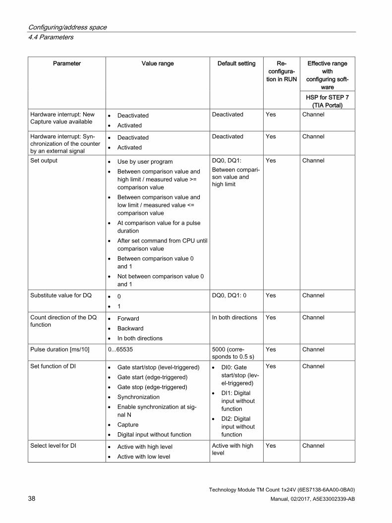
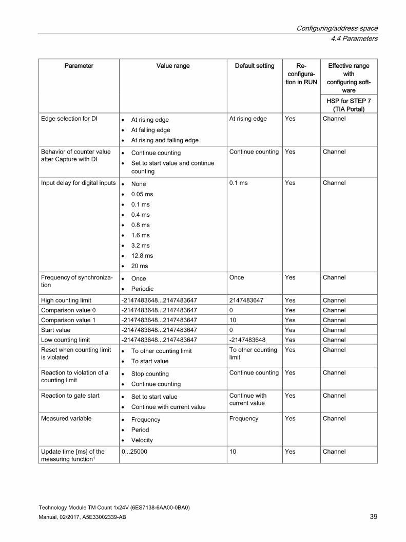
Technology Module TM Count 1x24V (6ES7138-6AA00-0BA0) 36 Manual, 02/2017, A5E33002339-AB
4.4.2 Parameters for operating with technology object "Counting and measurement"
Parameters of the TM Count 1x24V The following parameter settings are possible:
Table 4- 5 Settable parameters and their default setting in "Operating with technology object "Counting and measure-ment"" operating mode
Parameter Value range Default setting Re-configura-
tion in RUN
Effective range with
configuring soft-ware
HSP for STEP 7 (TIA Portal)
Operating mode • Use counter value as reference • Use measured value as reference
Use counter value as reference
No Channel
Sensor type • Sourcing output • Sinking output • Push-pull (sinking and sourcing
output)
Sourcing output Yes Channel
Reaction to CPU STOP • Output substitute value • Keep last value • Continue operation
Output substitute value
Yes Channel
Enable diagnostic interrupt on wire break
• Deactivated • Activated
Deactivated Yes Channel
Enable additional diagnos-tic interrupts
• Deactivated • Activated
Deactivated Yes Channel
Signal type • Pulse (A) • Pulse (A) and direction (B) • Count up (A), count down (B) • Incremental encoder (A, B phase-
shifted) • Incremental encoder (A, B, N)
Pulse (A) and direction (B)
Yes Channel
Signal evaluation for coun-ter inputs
• Single • Double • Quadruple
Single Yes Channel

Configuring/address space 4.4 Parameters
Technology Module TM Count 1x24V (6ES7138-6AA00-0BA0) Manual, 02/2017, A5E33002339-AB 37
Parameter Value range Default setting Re-configura-
tion in RUN
Effective range with
configuring soft-ware
HSP for STEP 7 (TIA Portal)
Filter frequency for counter inputs
• 100 Hz • 200 Hz • 500 Hz • 1 kHz • 2 kHz • 5 kHz • 10 kHz • 20 kHz • 50 kHz • 100 kHz • 200 kHz
200 kHz Yes Channel
Invert direction (counter inputs)1
• Deactivated • Activated
Deactivated Yes Channel
Reaction to signal N • No reaction to signal N • Synchronization at signal N • Capture at signal N
No reaction to signal N
Yes Channel
Hardware interrupt: Gate start
• Deactivated • Activated
Deactivated Yes Channel
Hardware interrupt: Gate stop
• Deactivated • Activated
Deactivated Yes Channel
Hardware interrupt: Over-flow (high counting limit violated)
• Deactivated • Activated
Deactivated Yes Channel
Hardware interrupt: Under-flow (low counting limit violated)
• Deactivated • Activated
Deactivated Yes Channel
Hardware interrupt: Direc-tion reversal
• Deactivated • Activated
Deactivated Yes Channel
Hardware interrupt: Com-parison event for DQ0 occurred
• Deactivated • Activated
Deactivated Yes Channel
Hardware interrupt: Com-parison event for DQ1 occurred
• Deactivated • Activated
Deactivated Yes Channel
Hardware interrupt: Zero crossing
• Deactivated • Activated
Deactivated Yes Channel
Configuring/address space 4.4 Parameters
Technology Module TM Count 1x24V (6ES7138-6AA00-0BA0) 38 Manual, 02/2017, A5E33002339-AB
Parameter Value range Default setting Re-configura-
tion in RUN
Effective range with
configuring soft-ware
HSP for STEP 7 (TIA Portal)
Hardware interrupt: New Capture value available
• Deactivated • Activated
Deactivated Yes Channel
Hardware interrupt: Syn-chronization of the counter by an external signal
• Deactivated • Activated
Deactivated Yes Channel
Set output • Use by user program • Between comparison value and
high limit / measured value >= comparison value
• Between comparison value and low limit / measured value <= comparison value
• At comparison value for a pulse duration
• After set command from CPU until comparison value
• Between comparison value 0 and 1
• Not between comparison value 0 and 1
DQ0, DQ1: Between compari-son value and high limit
Yes Channel
Substitute value for DQ • 0 • 1
DQ0, DQ1: 0 Yes Channel
Count direction of the DQ function
• Forward • Backward • In both directions
In both directions Yes Channel
Pulse duration [ms/10] 0...65535 5000 (corre-sponds to 0.5 s)
Yes Channel
Set function of DI • Gate start/stop (level-triggered) • Gate start (edge-triggered) • Gate stop (edge-triggered) • Synchronization • Enable synchronization at sig-
nal N • Capture • Digital input without function
• DI0: Gate start/stop (lev-el-triggered)
• DI1: Digital input without function
• DI2: Digital input without function
Yes Channel
Select level for DI • Active with high level • Active with low level
Active with high level
Yes Channel
Configuring/address space 4.4 Parameters
Technology Module TM Count 1x24V (6ES7138-6AA00-0BA0) Manual, 02/2017, A5E33002339-AB 39
Parameter Value range Default setting Re-configura-
tion in RUN
Effective range with
configuring soft-ware
HSP for STEP 7 (TIA Portal)
Edge selection for DI • At rising edge • At falling edge • At rising and falling edge
At rising edge Yes Channel
Behavior of counter value after Capture with DI
• Continue counting • Set to start value and continue
counting
Continue counting Yes Channel
Input delay for digital inputs • None • 0.05 ms • 0.1 ms • 0.4 ms • 0.8 ms • 1.6 ms • 3.2 ms • 12.8 ms • 20 ms
0.1 ms Yes Channel
Frequency of synchroniza-tion
• Once • Periodic
Once Yes Channel
High counting limit -2147483648...2147483647 2147483647 Yes Channel Comparison value 0 -2147483648...2147483647 0 Yes Channel Comparison value 1 -2147483648...2147483647 10 Yes Channel Start value -2147483648...2147483647 0 Yes Channel Low counting limit -2147483648...2147483647 -2147483648 Yes Channel Reset when counting limit is violated
• To other counting limit • To start value
To other counting limit
Yes Channel
Reaction to violation of a counting limit
• Stop counting • Continue counting
Continue counting Yes Channel
Reaction to gate start • Set to start value • Continue with current value
Continue with current value
Yes Channel
Measured variable • Frequency • Period • Velocity
Frequency Yes Channel
Update time [ms] of the measuring function1
0...25000 10 Yes Channel

Configuring/address space 4.4 Parameters
Technology Module TM Count 1x24V (6ES7138-6AA00-0BA0) 40 Manual, 02/2017, A5E33002339-AB
Parameter Value range Default setting Re-configura-
tion in RUN
Effective range with
configuring soft-ware
HSP for STEP 7 (TIA Portal)
Time base for velocity measurement
• 1 ms • 10 ms • 100 ms • 1 s • 60 s/1 min
60 s/1 min Yes Channel
Increments per unit 1...65535 1 Yes Channel Hysteresis 0...255 0 Yes Channel Potential group • Use the potential group of the left
module (dark BaseUnit) • Enable new potential group (light
BaseUnit)
Use the potential group of the left module (dark BaseUnit)
No Module
Configuring/address space 4.4 Parameters
Technology Module TM Count 1x24V (6ES7138-6AA00-0BA0) Manual, 02/2017, A5E33002339-AB 41
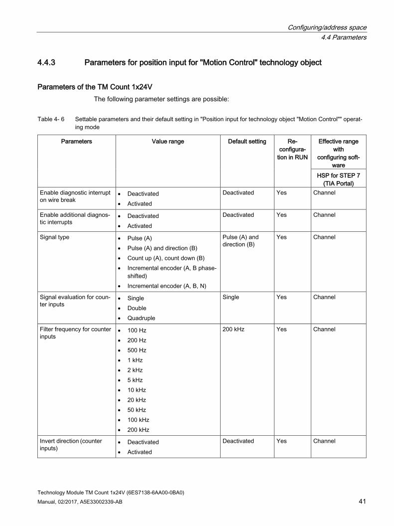
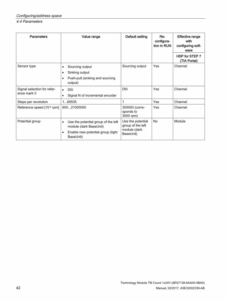
4.4.3 Parameters for position input for "Motion Control" technology object
Parameters of the TM Count 1x24V The following parameter settings are possible:
Table 4- 6 Settable parameters and their default setting in "Position input for technology object "Motion Control"" operat-ing mode
Parameters Value range Default setting Re-configura-
tion in RUN
Effective range with
configuring soft-ware
HSP for STEP 7 (TIA Portal)
Enable diagnostic interrupt on wire break
• Deactivated • Activated
Deactivated Yes Channel
Enable additional diagnos-tic interrupts
• Deactivated • Activated
Deactivated Yes Channel
Signal type • Pulse (A) • Pulse (A) and direction (B) • Count up (A), count down (B) • Incremental encoder (A, B phase-
shifted) • Incremental encoder (A, B, N)
Pulse (A) and direction (B)
Yes Channel
Signal evaluation for coun-ter inputs
• Single • Double • Quadruple
Single Yes Channel
Filter frequency for counter inputs
• 100 Hz • 200 Hz • 500 Hz • 1 kHz • 2 kHz • 5 kHz • 10 kHz • 20 kHz • 50 kHz • 100 kHz • 200 kHz
200 kHz Yes Channel
Invert direction (counter inputs)
• Deactivated • Activated
Deactivated Yes Channel
Configuring/address space 4.4 Parameters
Technology Module TM Count 1x24V (6ES7138-6AA00-0BA0) 42 Manual, 02/2017, A5E33002339-AB
Parameters Value range Default setting Re-configura-
tion in RUN
Effective range with
configuring soft-ware
HSP for STEP 7 (TIA Portal)
Sensor type • Sourcing output • Sinking output • Push-pull (sinking and sourcing
output)
Sourcing output Yes Channel
Signal selection for refer-ence mark 0
• DI0 • Signal N of incremental encoder
DI0 Yes Channel
Steps per revolution 1...65535 1 Yes Channel Reference speed [10-2 rpm] 600...21000000 300000 (corre-
sponds to 3000 rpm)
Yes Channel
Potential group • Use the potential group of the left module (dark BaseUnit)
• Enable new potential group (light BaseUnit)
Use the potential group of the left module (dark BaseUnit)
No Module

Configuring/address space 4.4 Parameters
Technology Module TM Count 1x24V (6ES7138-6AA00-0BA0) Manual, 02/2017, A5E33002339-AB 43
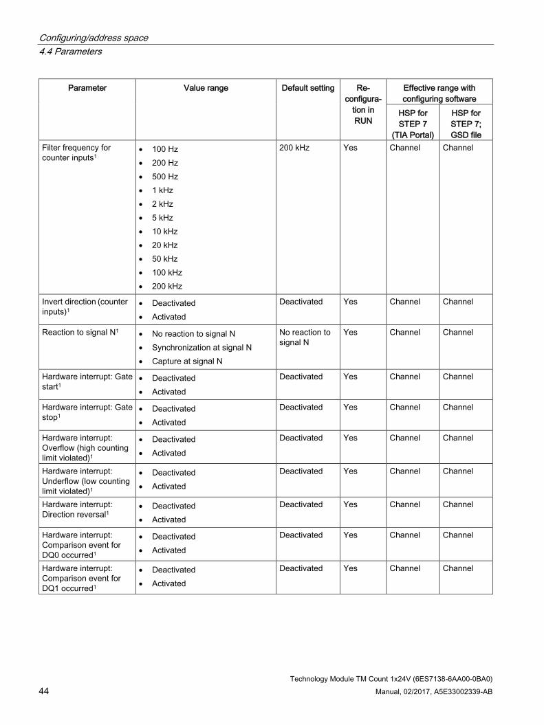
4.4.4 Parameters for manual operation (without technology object)
Parameters of the TM Count 1x24V The following parameter settings are possible:
Table 4- 7 Settable parameters and their default setting in "Manual operation (without technology object)" operating mode
Parameter Value range Default setting Re-configura-
tion in RUN
Effective range with configuring software
HSP for STEP 7
(TIA Portal)
HSP for STEP 7; GSD file
Operating mode3 • Counting • Measuring
Counting No Channel Channel
Sensor type • Sourcing output • Sinking output • Push-pull (sinking and sourcing
output)
Sourcing out-put
Yes Channel Channel
Reaction to CPU STOP1 • Output substitute value • Keep last value • Continue operation
Output substi-tute value
Yes Channel Channel
Enabling diagnostic interrupts for wire break2
• Deactivated • Activated
Deactivated Yes Channel Channel
Enable additional diag-nostic interrupts
• Deactivated • Activated
Deactivated Yes Channel Channel
Signal type • Pulse (A) • Pulse (A) and direction (B) • Count up (A), count down (B) • Incremental encoder (A, B
phase-shifted) • Incremental encoder (A, B, N)
Pulse (A) and direction (B)
Yes Channel Channel
Signal evaluation for counter inputs
• Single • Double • Quadruple
Single Yes Channel Channel
Configuring/address space 4.4 Parameters
Technology Module TM Count 1x24V (6ES7138-6AA00-0BA0) 44 Manual, 02/2017, A5E33002339-AB
Parameter Value range Default setting Re-configura-
tion in RUN
Effective range with configuring software
HSP for STEP 7
(TIA Portal)
HSP for STEP 7; GSD file
Filter frequency for counter inputs1
• 100 Hz • 200 Hz • 500 Hz • 1 kHz • 2 kHz • 5 kHz • 10 kHz • 20 kHz • 50 kHz • 100 kHz • 200 kHz
200 kHz Yes Channel Channel
Invert direction (counter inputs)1
• Deactivated • Activated
Deactivated Yes Channel Channel
Reaction to signal N1 • No reaction to signal N • Synchronization at signal N • Capture at signal N
No reaction to signal N
Yes Channel Channel
Hardware interrupt: Gate start1
• Deactivated • Activated
Deactivated Yes Channel Channel
Hardware interrupt: Gate stop1
• Deactivated • Activated
Deactivated Yes Channel Channel
Hardware interrupt: Overflow (high counting limit violated)1
• Deactivated • Activated
Deactivated Yes Channel Channel
Hardware interrupt: Underflow (low counting limit violated)1
• Deactivated • Activated
Deactivated Yes Channel Channel
Hardware interrupt: Direction reversal1
• Deactivated • Activated
Deactivated Yes Channel Channel
Hardware interrupt: Comparison event for DQ0 occurred1
• Deactivated • Activated
Deactivated Yes Channel Channel
Hardware interrupt: Comparison event for DQ1 occurred1
• Deactivated • Activated
Deactivated Yes Channel Channel

Configuring/address space 4.4 Parameters
Technology Module TM Count 1x24V (6ES7138-6AA00-0BA0) Manual, 02/2017, A5E33002339-AB 45
Parameter Value range Default setting Re-configura-
tion in RUN
Effective range with configuring software
HSP for STEP 7
(TIA Portal)
HSP for STEP 7; GSD file
Hardware interrupt: Zero crossing1
• Deactivated • Activated
Deactivated Yes Channel Channel
Hardware interrupt: New Capture value available1
• Deactivated • Activated
Deactivated Yes Channel Channel
Hardware interrupt: Synchronization of the counter by an external signal1
• Deactivated • Activated
Deactivated Yes Channel Channel
Set output • Use by user program • Between comparison value and
high limit / measured value >= comparison value
• Between comparison value and low limit / measured value <= comparison value
• At comparison value for a pulse duration
• After set command from CPU until comparison value
• Between comparison value 0 and 1
• Not between comparison value 0 and 1
DQ0, DQ1: Between com-parison value and high limit
Yes Channel Channel
Substitute value for DQ1 • 0 • 1
DQ0, DQ1: 0 Yes Channel Channel
Count direction of the DQ function1
• Forward • Backward • In both directions
In both direc-tions
Yes Channel Channel
Pulse duration [ms/10]1 0...65535 5000 (corre-sponds to 0.5 s)
Yes Channel Channel

Configuring/address space 4.4 Parameters
Technology Module TM Count 1x24V (6ES7138-6AA00-0BA0) 46 Manual, 02/2017, A5E33002339-AB
Parameter Value range Default setting Re-configura-
tion in RUN
Effective range with configuring software
HSP for STEP 7
(TIA Portal)
HSP for STEP 7; GSD file
Set function of DI • Gate start/stop (level-triggered) • Gate start (edge-triggered) • Gate stop (edge-triggered) • Synchronization • Enable synchronization at signal
N • Capture • Digital input without function
• DI0: Gate start/stop (level-triggered)
• DI1: Digital input with-out function
• DI2: Digital input with-out function
Yes Channel Channel
Select level for DI1 • Active with high level • Active with low level
Active with high level
Yes Channel Channel
Edge selection for DI1 • At rising edge • At falling edge • At rising and falling edge
At rising edge Yes Channel Channel
Behavior of counter value after Capture with DI 1
• Continue counting • Set to start value and continue
counting
Continue counting
Yes Channel Channel
Input delay for digital inputs1
• None • 0.05 ms • 0.1 ms • 0.4 ms • 0.8 ms • 1.6 ms • 3.2 ms • 12.8 ms • 20 ms
0.1 ms Yes Channel Channel
Frequency of synchroni-zation1
• Once • Periodic
Once Yes Channel Channel
High counting limit1 -2147483648...2147483647 2147483647 Yes Channel Channel Comparison value 01 -2147483648...2147483647 0 Yes Channel Channel Comparison value 11 -2147483648...2147483647 10 Yes Channel Channel Start value1 -2147483648...2147483647 0 Yes Channel Channel Low counting limit1 -2147483648...2147483647 -2147483648 Yes Channel Channel Reset when counting limit is violated
• To other counting limit • To start value
To other count-ing limit
Yes Channel Channel

Configuring/address space 4.4 Parameters
Technology Module TM Count 1x24V (6ES7138-6AA00-0BA0) Manual, 02/2017, A5E33002339-AB 47
Parameter Value range Default setting Re-configura-
tion in RUN
Effective range with configuring software
HSP for STEP 7
(TIA Portal)
HSP for STEP 7; GSD file
Reaction to violation of a counting limit
• Stop counting • Continue counting
Continue counting
Yes Channel Channel
Reaction to gate start • Set to start value • Continue with current value
Continue with current value
Yes Channel Channel
Measured variable • Frequency • Period • Velocity
Frequency Yes Channel Channel
Update time [ms] of the measuring function1
0...25000 10 Yes Channel Channel
Time base for velocity measurement1
• 1 ms • 10 ms • 100 ms • 1 s • 60 s/1 min
60 s/1 min Yes Channel Channel
Increments per unit1 1...65535 1 Yes Channel Channel Hysteresis1 0...255 0 Yes Channel Channel Potential group • Use the potential group of the
left module (dark BaseUnit) • Enable new potential group (light
BaseUnit)
Use the poten-tial group of the left module (dark BaseUnit)
No Module Module
1 Due to the limited number of parameters at a maximum of 244 bytes per ET 200SP station with a PROFIBUS GSD configuration, the possible parameter settings are restricted. The parameter is downloaded to the module with the de-fault setting. If your PROFIBUS master supports the "Read/write data record" function, you can set these parameters using data record 128.
2 When a GSD file is used, this diagnostic interrupt is activated via the "Enable additional diagnostic interrupts" parameter and cannot be set separately.
3 When configuring with HSP for STEP 7 or with a GSD file, you define the operating mode by the selection of the module name.
Configuring/address space 4.4 Parameters
Technology Module TM Count 1x24V (6ES7138-6AA00-0BA0) 48 Manual, 02/2017, A5E33002339-AB
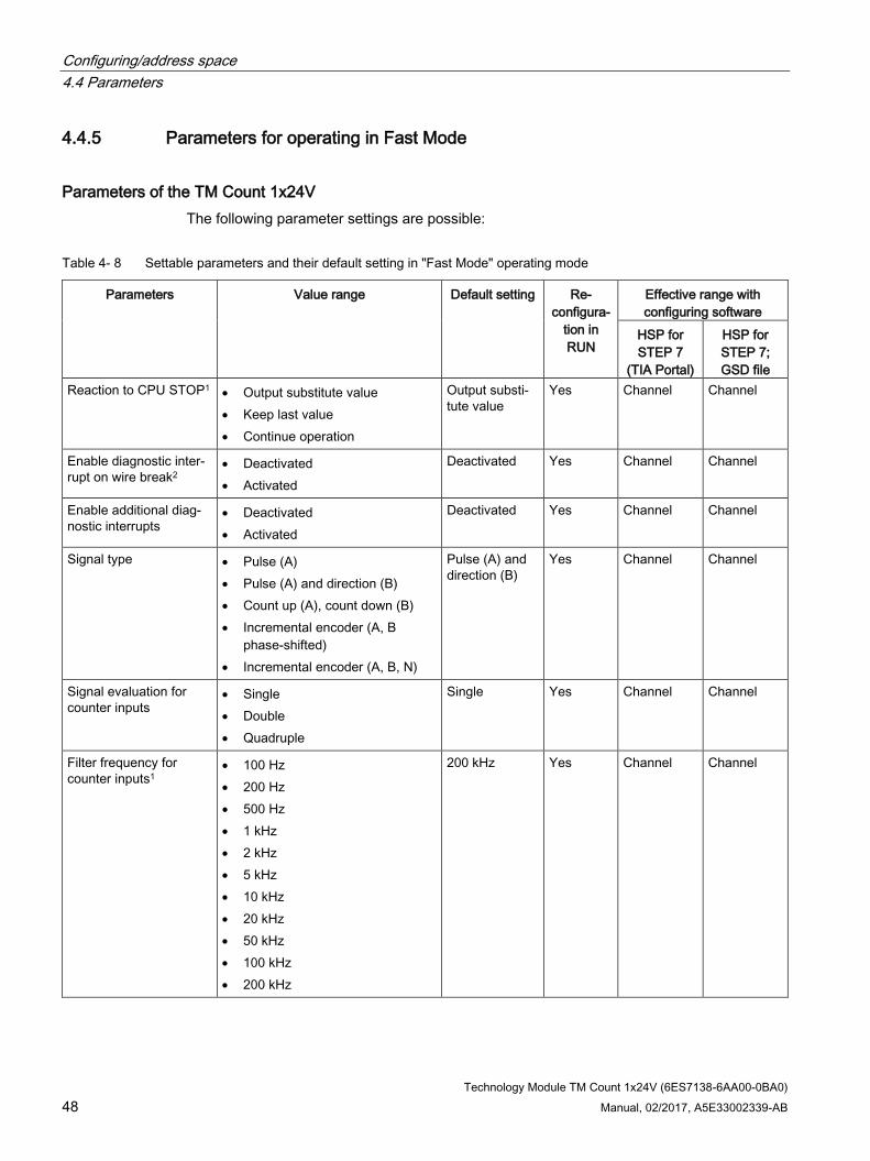
4.4.5 Parameters for operating in Fast Mode
Parameters of the TM Count 1x24V The following parameter settings are possible:
Table 4- 8 Settable parameters and their default setting in "Fast Mode" operating mode
Parameters Value range Default setting Re-configura-
tion in RUN
Effective range with configuring software
HSP for STEP 7
(TIA Portal)
HSP for STEP 7; GSD file
Reaction to CPU STOP1 • Output substitute value • Keep last value • Continue operation
Output substi-tute value
Yes Channel Channel
Enable diagnostic inter-rupt on wire break2
• Deactivated • Activated
Deactivated Yes Channel Channel
Enable additional diag-nostic interrupts
• Deactivated • Activated
Deactivated Yes Channel Channel
Signal type • Pulse (A) • Pulse (A) and direction (B) • Count up (A), count down (B) • Incremental encoder (A, B
phase-shifted) • Incremental encoder (A, B, N)
Pulse (A) and direction (B)
Yes Channel Channel
Signal evaluation for counter inputs
• Single • Double • Quadruple
Single Yes Channel Channel
Filter frequency for counter inputs1
• 100 Hz • 200 Hz • 500 Hz • 1 kHz • 2 kHz • 5 kHz • 10 kHz • 20 kHz • 50 kHz • 100 kHz • 200 kHz
200 kHz Yes Channel Channel

Configuring/address space 4.4 Parameters
Technology Module TM Count 1x24V (6ES7138-6AA00-0BA0) Manual, 02/2017, A5E33002339-AB 49
Parameters Value range Default setting Re-configura-
tion in RUN
Effective range with configuring software
HSP for STEP 7
(TIA Portal)
HSP for STEP 7; GSD file
Invert direction (counter inputs)1
• Deactivated • Activated
Deactivated Yes Channel Channel
Reaction to signal N1 • No reaction to signal N • Synchronization at signal N
No reaction to signal N
Yes Channel Channel
Sensor type • Sourcing output • Sinking output • Push-pull (sinking and sourcing
output)
Sourcing out-put
Yes Channel Channel
Set output • Use by user program • Between comparison value and
high counting limit • Between comparison value and
low counter limit • At comparison value for a pulse
duration • After set command from CPU
until comparison value • Between comparison value 0
and 1
DQ0, DQ1: Digital output without function
Yes Channel Channel
Substitute value for DQ1 • 0 • 1
DQ0, DQ1: 0 Yes Channel Channel
Count direction of the DQ function1
• Forward • Backward • In both directions
In both direc-tions
Yes Channel Channel
Pulse duration [ms/10]1 0...65535 5000 (corre-sponds to 0.5 s)
Yes Channel Channel
Set function of DI • Gate start/stop (level-triggered) • Gate start (edge-triggered) • Gate stop (edge-triggered) • Synchronization • Enable synchronization at sig-
nal N • Digital input without function
Digital input without function
Yes Channel Channel
Select level for DI1 • Active with high level • Active with low level
Active with high level
Yes Channel Channel

Configuring/address space 4.4 Parameters
Technology Module TM Count 1x24V (6ES7138-6AA00-0BA0) 50 Manual, 02/2017, A5E33002339-AB
Parameters Value range Default setting Re-configura-
tion in RUN
Effective range with configuring software
HSP for STEP 7
(TIA Portal)
HSP for STEP 7; GSD file
Edge selection for DI1 • At rising edge • At falling edge
At rising edge Yes Channel Channel
Input delay for digital inputs1
• None • 0.05 ms • 0.1 ms • 0.4 ms • 0.8 ms • 1.6 ms • 3.2 ms • 12.8 ms • 20 ms
0.1 ms Yes Channel Channel
Frequency of synchroni-zation1
• Once • Periodic
Once Yes Channel Channel
Count direction for syn-chronization
• Up • Down • In both directions
Up Yes Channel Channel
High counting limit1 1...33554431 33554431 Yes Channel Channel Comparison value 01 0...33554430 0 Yes Channel Channel Comparison value 11 0...33554431 10 Yes Channel Channel Start value1 0...33554431 0 Yes Channel Channel Low counting limit1 0...33554430 0 Yes Channel Channel Reset when counting limit is violated
• To other counting limit • To start value
To other count-ing limit
Yes Channel Channel
Reaction to violation of a counting limit
• Stop counting • Continue counting
Continue counting
Yes Channel Channel
Reaction to gate start • Set to start value • Continue with current value
Continue with current value
Yes Channel Channel

Configuring/address space 4.4 Parameters
Technology Module TM Count 1x24V (6ES7138-6AA00-0BA0) Manual, 02/2017, A5E33002339-AB 51
Parameters Value range Default setting Re-configura-
tion in RUN
Effective range with configuring software
HSP for STEP 7
(TIA Portal)
HSP for STEP 7; GSD file
Hysteresis1 0...255 0 Yes Channel Channel Potential group • Use the potential group of the
left module (dark BaseUnit) • Enable new potential group (light
BaseUnit)
Use the poten-tial group of the left module (dark BaseUnit)
No Module Module
1 Due to the limited number of parameters at a maximum of 244 bytes per ET 200SP station with a PROFIBUS GSD configuration, the possible parameter settings are restricted. The parameter is downloaded to the module with the de-fault setting. If your PROFIBUS master supports the "Read/write data record" function, you can set these parameters using data record 128.
2 When a GSD file is used, this diagnostic interrupt is activated via the "Enable additional diagnostic interrupts" parameter and cannot be set separately.

Configuring/address space 4.5 Control and feedback interface
Technology Module TM Count 1x24V (6ES7138-6AA00-0BA0) 52 Manual, 02/2017, A5E33002339-AB
4.5 Control and feedback interface Information on using the control and feedback interface can be found in the section Configuring (Page 28).
A detailed description of the control and feedback bits is available in the Counting, Measurement and Position Detection function manual, which can be downloaded on the Internet (http://support.automation.siemens.com/WW/view/en/59709820).
Note
Except in "Fast Mode" operating mode, the control and feedback interface is compatible with the control and feedback interface of the TM Count 2x24V technology module of the S7-1500 automation system.
Note Operating with technology object
If you are using a technology object, the control and feedback interface is operated by the technology object.
Fast Mode
If you are using the "Fast Mode" operating mode, a control interface is not available. The feedback interface (Page 56) has an adapted assignment in Fast Mode. In addition, you can find explanations about the feedback bits (Page 56).

Configuring/address space 4.5 Control and feedback interface
Technology Module TM Count 1x24V (6ES7138-6AA00-0BA0) Manual, 02/2017, A5E33002339-AB 53
4.5.1 Assignment of the control interface The user program uses the control interface to influence the behavior of the technology module.
Control interface The following table shows control interface assignment:
Byte offset from start address
Parameter Meaning
0 … 3 Slot 0 DINT or REAL: Load value (the significance of the value is specified in LD_SLOT_0)
4 … 7 Slot 1 DINT or REAL: Load value (the significance of the value is specified in LD_SLOT_1)
8 LD_SLOT_0* Specifies the significance of the value in Slot 0 Bit 3 Bit 2 Bit 1 Bit 0 0 0 0 0 No action, idle 0 0 0 1 Load counter value 0 0 1 0 Invalid 0 0 1 1 Load start value 0 1 0 0 Load comparison value 0 0 1 0 1 Load comparison value 1 0 1 1 0 Load low counting limit 0 1 1 1 Load high counting limit 1 0 0 0 Invalid to 1 1 1 1
LD_SLOT_1* Specifies the significance of the value in Slot 1 Bit 7 Bit 6 Bit 5 Bit 4 0 0 0 0 No action, idle 0 0 0 1 Load counter value 0 0 1 0 Invalid 0 0 1 1 Load start value 0 1 0 0 Load comparison value 0 0 1 0 1 Load comparison value 1 0 1 1 0 Load low counting limit 0 1 1 1 Load high counting limit 1 0 0 0 Invalid to 1 1 1 1
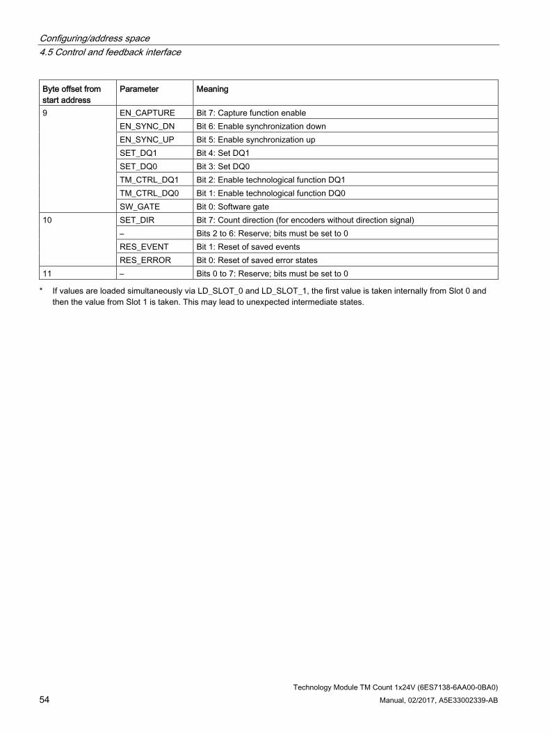
Configuring/address space 4.5 Control and feedback interface
Technology Module TM Count 1x24V (6ES7138-6AA00-0BA0) 54 Manual, 02/2017, A5E33002339-AB
Byte offset from start address
Parameter Meaning
9 EN_CAPTURE Bit 7: Capture function enable EN_SYNC_DN Bit 6: Enable synchronization down EN_SYNC_UP Bit 5: Enable synchronization up SET_DQ1 Bit 4: Set DQ1 SET_DQ0 Bit 3: Set DQ0 TM_CTRL_DQ1 Bit 2: Enable technological function DQ1 TM_CTRL_DQ0 Bit 1: Enable technological function DQ0 SW_GATE Bit 0: Software gate
10 SET_DIR Bit 7: Count direction (for encoders without direction signal) – Bits 2 to 6: Reserve; bits must be set to 0 RES_EVENT Bit 1: Reset of saved events RES_ERROR Bit 0: Reset of saved error states
11 – Bits 0 to 7: Reserve; bits must be set to 0 * If values are loaded simultaneously via LD_SLOT_0 and LD_SLOT_1, the first value is taken internally from Slot 0 and
then the value from Slot 1 is taken. This may lead to unexpected intermediate states.
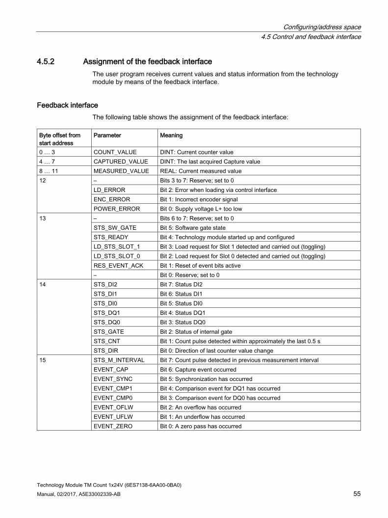
Configuring/address space 4.5 Control and feedback interface
Technology Module TM Count 1x24V (6ES7138-6AA00-0BA0) Manual, 02/2017, A5E33002339-AB 55
4.5.2 Assignment of the feedback interface The user program receives current values and status information from the technology module by means of the feedback interface.
Feedback interface The following table shows the assignment of the feedback interface:
Byte offset from start address
Parameter Meaning
0 … 3 COUNT_VALUE DINT: Current counter value 4 … 7 CAPTURED_VALUE DINT: The last acquired Capture value 8 … 11 MEASURED_VALUE REAL: Current measured value 12 – Bits 3 to 7: Reserve; set to 0
LD_ERROR Bit 2: Error when loading via control interface ENC_ERROR Bit 1: Incorrect encoder signal POWER_ERROR Bit 0: Supply voltage L+ too low
13 – Bits 6 to 7: Reserve; set to 0 STS_SW_GATE Bit 5: Software gate state STS_READY Bit 4: Technology module started up and configured LD_STS_SLOT_1 Bit 3: Load request for Slot 1 detected and carried out (toggling) LD_STS_SLOT_0 Bit 2: Load request for Slot 0 detected and carried out (toggling) RES_EVENT_ACK Bit 1: Reset of event bits active – Bit 0: Reserve; set to 0
14 STS_DI2 Bit 7: Status DI2 STS_DI1 Bit 6: Status DI1 STS_DI0 Bit 5: Status DI0 STS_DQ1 Bit 4: Status DQ1 STS_DQ0 Bit 3: Status DQ0 STS_GATE Bit 2: Status of internal gate STS_CNT Bit 1: Count pulse detected within approximately the last 0.5 s STS_DIR Bit 0: Direction of last counter value change
15 STS_M_INTERVAL Bit 7: Count pulse detected in previous measurement interval EVENT_CAP Bit 6: Capture event occurred EVENT_SYNC Bit 5: Synchronization has occurred EVENT_CMP1 Bit 4: Comparison event for DQ1 has occurred EVENT_CMP0 Bit 3: Comparison event for DQ0 has occurred EVENT_OFLW Bit 2: An overflow has occurred EVENT_UFLW Bit 1: An underflow has occurred EVENT_ZERO Bit 0: A zero pass has occurred
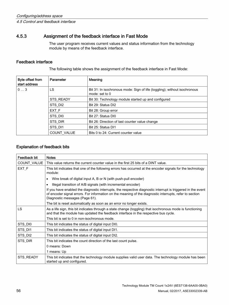
Configuring/address space 4.5 Control and feedback interface
Technology Module TM Count 1x24V (6ES7138-6AA00-0BA0) 56 Manual, 02/2017, A5E33002339-AB
4.5.3 Assignment of the feedback interface in Fast Mode The user program receives current values and status information from the technology module by means of the feedback interface.
Feedback interface The following table shows the assignment of the feedback interface in Fast Mode:
Byte offset from start address
Parameter Meaning
0 … 3 LS Bit 31: In isochronous mode: Sign of life (toggling); without isochronous mode: set to 0
STS_READY Bit 30: Technology module started up and configured STS_DI2 Bit 29: Status DI2 EXT_F Bit 28: Group error STS_DI0 Bit 27: Status DI0 STS_DIR Bit 26: Direction of last counter value change STS_DI1 Bit 25: Status DI1 COUNT_VALUE Bits 0 to 24: Current counter value
Explanation of feedback bits Feedback bit Notes COUNT_VALUE This value returns the current counter value in the first 25 bits of a DINT value. EXT_F This bit indicates that one of the following errors has occurred at the encoder signals for the technology
module: • Wire break of digital input A, B or N (with push-pull encoder) • Illegal transition of A/B signals (with incremental encoder) If you have enabled the diagnostic interrupts, the respective diagnostic interrupt is triggered in the event of encoder signal errors. For information on the meaning of the diagnostic interrupts, refer to section Diagnostic messages (Page 61). The bit is reset automatically as soon as an error no longer exists.
LS As a life sign, this bit indicates through a state change (toggling) that isochronous mode is functioning and that the module has updated the feedback interface in the respective bus cycle. This bit is set to 0 in non-isochronous mode.
STS_DI0 This bit indicates the status of digital input DI0. STS_DI1 This bit indicates the status of digital input DI1. STS_DI2 This bit indicates the status of digital input DI2. STS_DIR This bit indicates the count direction of the last count pulse.
0 means: Down 1 means: Up
STS_READY This bit indicates that the technology module supplies valid user data. The technology module has been started up and configured.

Technology Module TM Count 1x24V (6ES7138-6AA00-0BA0) 57 Manual, 02/2017, A5E33002339-AB
Interrupts/diagnostic messages 5 5.1 Status and error displays
LEDs The figure below shows you the LED displays (status and error displays) of TM Count 1x24V.
① DIAG (green/red) ⑧ Status of DI1 (green) ② Status A (green) ⑨ Status of DI2 (green) ③ Status B (green) ⑩ Status of DQ0 (green) ④ Status N (green) ⑪ Status of DQ1 (green) ⑤ 24 VDC (green) ⑫ Status UP (green) ⑥ PWR (green) ⑬ Status DN (green) ⑦ Status of DI0 (green)
Figure 5-1 LEDs of the TM Count 1x24V
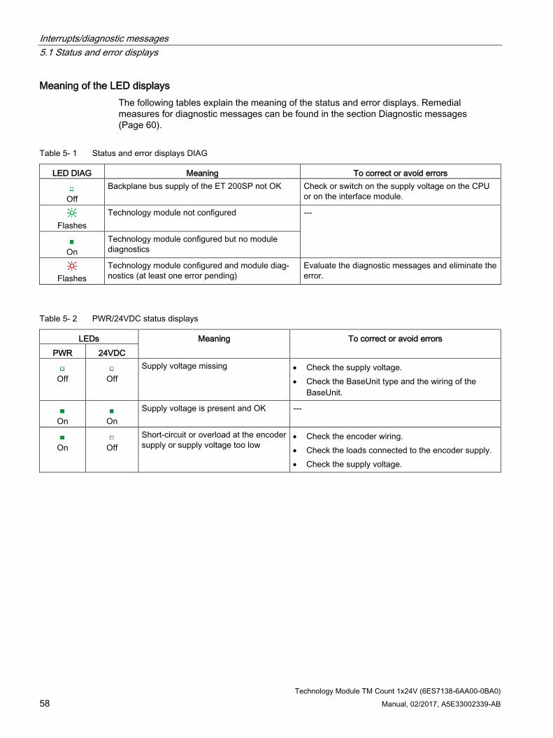
Interrupts/diagnostic messages 5.1 Status and error displays
Technology Module TM Count 1x24V (6ES7138-6AA00-0BA0) 58 Manual, 02/2017, A5E33002339-AB
Meaning of the LED displays The following tables explain the meaning of the status and error displays. Remedial measures for diagnostic messages can be found in the section Diagnostic messages (Page 60).
Table 5- 1 Status and error displays DIAG
LED DIAG Meaning To correct or avoid errors
Off
Backplane bus supply of the ET 200SP not OK Check or switch on the supply voltage on the CPU or on the interface module.
Flashes
Technology module not configured ---
On
Technology module configured but no module diagnostics
Flashes
Technology module configured and module diag-nostics (at least one error pending)
Evaluate the diagnostic messages and eliminate the error.
Table 5- 2 PWR/24VDC status displays
LEDs Meaning To correct or avoid errors PWR 24VDC
Off
Off
Supply voltage missing • Check the supply voltage. • Check the BaseUnit type and the wiring of the
BaseUnit.
On
On
Supply voltage is present and OK ---
On
Off
Short-circuit or overload at the encoder supply or supply voltage too low
• Check the encoder wiring. • Check the loads connected to the encoder supply. • Check the supply voltage.

Interrupts/diagnostic messages 5.1 Status and error displays
Technology Module TM Count 1x24V (6ES7138-6AA00-0BA0) Manual, 02/2017, A5E33002339-AB 59
ChannelLEDs
The A, B, N and DIm LEDs indicate the current level of the associated signals. The LEDs of the digital outputs DQm indicate the desired state.
The LEDs UP and DN indicate the logical counting direction.
The flashing frequency of the channel LEDs is limited to ca. 12 Hz. If higher frequencies are present, the channel LEDs will flash at 12 Hz instead of indicating the current status.
Table 5- 3 A/B/N/DIm/DQm status displays
A/B/N/DIm/DQm LEDs Meaning
Off
Counter input / digital input / digital output at 0 level
On
Counter input / digital input / digital output at 1 level
Table 5- 4 Status displays UP/DN
LEDs Meaning UP DN
Off
Off
No count pulse has been detected for the last 0.5 s.
On
Off
The last count pulse has incremented the counter and took place no more than 0.5 s ago.
Off
On
The last count pulse has decremented the counter and took place no more than 0.5 s ago.

Interrupts/diagnostic messages 5.2 Diagnostic messages
Technology Module TM Count 1x24V (6ES7138-6AA00-0BA0) 60 Manual, 02/2017, A5E33002339-AB
5.2 Diagnostic messages
Enabling the diagnostic interrupts You enable the diagnostic interrupts in the basic parameters of the device configuration.
The technology module can trigger the following diagnostic interrupts:
Table 5- 5 Possible diagnostic interrupts
Diagnostic interrupt Monitoring • Parameter assignment error • Hardware interrupt lost • Module temporarily unavailable • Internal error • Watchdog tripped. Module is defective.
Monitoring is always active. A diagnostic interrupt is triggered each time an error is detected.
• Wire break at digital input A, B or N Monitoring is active if a push-pull switching encoder has been configured. A detected error only triggers a diagnostic interrupt if "Enable diagnostic interrupt for wire break" has been enabled in the device configura-tion.
• Error • Load voltage missing • Short circuit or overload at external encoder supply • Error at the digital outputs • Supply voltage error1 • Illegal A/B signal ratio • Overheating
Monitoring is always active. A detected error only triggers a diagnostic interrupt if "Enable additional diagnostic interrupts" has been enabled in the device configuration.
1 No longer available as of module version V1.2. This case is then taken into account by diagnostic interrupt "Load volt-age missing".

Interrupts/diagnostic messages 5.2 Diagnostic messages
Technology Module TM Count 1x24V (6ES7138-6AA00-0BA0) Manual, 02/2017, A5E33002339-AB 61
Reactions to a diagnostic interrupt The following happens when an event occurs that triggers a diagnostic interrupt:
● The DIAG LED flashes red.
When you have eliminated all errors, the DIAG LED stops flashing red and turns green.
● The S7-1500 CPU interrupts the processing of the user program. The diagnostic interrupt OB (e.g. OB 82) is called. The event that triggered the interrupt is entered in the start information of the diagnostic interrupt OB.
● The S7-1500 CPU remains in RUN, even if no diagnostic interrupt OB is present in the CPU. The technology module continues working unchanged if this is possible despite the error.
Detailed information on the error event can be obtained in the error organization block with instruction "RALRM" (read additional interrupt information), in the information system of STEP 7 and in the Diagnostics function manual (https://support.industry.siemens.com/cs/ww/en/view/59192926), section "System diagnostics by means of the user program".
If the module is being operated as a distributed module in an ET 200SP system with PROFIBUS DP, you have the option of reading out diagnostic data with the RDREC or RD_REC instruction using data record 0 and 1. For the structure of the data records, refer to the product manual for the IM 155-5 DP ST interface module, which is available for download on the Internet (https://support.industry.siemens.com/cs/ww/en/view/78324181).
Diagnostic messages The diagnostics are displayed as plain text in STEP 7 (TIA Portal) in the online and diagnostics view. You can evaluate the error codes with the user program.
The following diagnostics can be signaled:
Table 5- 6 Diagnostic alarms, their meaning and remedies
Diagnostic alarm Error code
Meaning Remedy
Error 9H • Internal module error occurred • Possible cause: Technology module defec-
tive
Replace technology module
Parameter as-signment error
10H • The received parameter data record is invalid
• The configured BaseUnit is not the used BaseUnit
• Check parameter data record • Check BaseUnit
Load voltage miss-ing
11H • Undervoltage • Supply voltage L+ of technology module
missing • Wiring of supply voltage L+ faulty
• Check BaseUnit type • Check supply voltage L+ on the Ba-
seUnit • Check wiring of supply voltage L+ • Check total consumption of the load
group

Interrupts/diagnostic messages 5.2 Diagnostic messages
Technology Module TM Count 1x24V (6ES7138-6AA00-0BA0) 62 Manual, 02/2017, A5E33002339-AB
Diagnostic alarm Error code
Meaning Remedy
Hardware interrupt lost
16H • Module cannot send an interrupt because a previous interrupt has not been processed
• Possible cause: Too many hardware inter-rupts in too short a time
• Change interrupt processing in the CPU and re-assign technology module parameters correspondingly
• Check frequency of interrupts from the process
Chan-nel/component temporarily una-vailable
1FH • Firmware update in progress
or update has been canceled.
The module reads no
process values in this state.
• Wait for firmware update • If firmware update aborts:
– Check minimum firmware version required
– Check supply voltage – Repeat firmware update
Internal error 100H Technology module defective Replace technology module Watchdog tripped. Module is defec-tive.
103H Firmware error Run firmware update Technology module defective Replace technology module
Short circuit or overload at exter-nal encoder supply
10EH • Error at encoder supply • Possible causes:
– Short circuit – Overload
• Check encoder wiring • Check consumers connected to en-
coder supply
Error at the digital outputs
10FH • Error at the digital outputs • Possible causes:
– Short circuit – Overload
• Check wiring at the digital outputs • Check consumers connected to the
digital outputs
Supply voltage error1
110H • Error at supply voltage L+ • Possible causes:
– Low voltage – Wiring of L+ supply voltage defective
• Check supply voltage L+ on the Ba-seUnit
• Check wiring of supply voltage L+ • Check total consumption of the load
group
Illegal A/B signal ratio
500H • Time profile of signals A and B of the in-cremental encoder does not meet certain specifications
• Possible causes: – Signal frequency too high – Encoder faulty – Process wiring faulty
• Check process wiring • Check encoder/sensor • Check parameter assignment
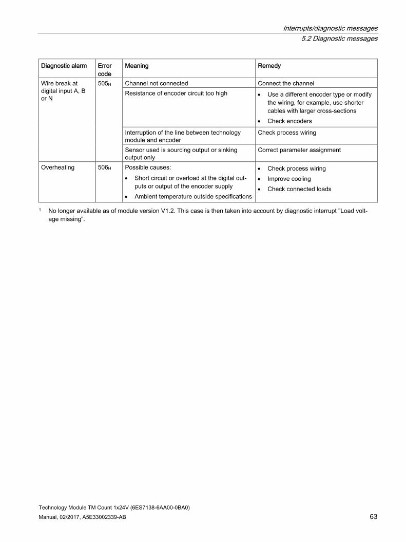
Interrupts/diagnostic messages 5.2 Diagnostic messages
Technology Module TM Count 1x24V (6ES7138-6AA00-0BA0) Manual, 02/2017, A5E33002339-AB 63
Diagnostic alarm Error code
Meaning Remedy
Wire break at digital input A, B or N
505H Channel not connected Connect the channel Resistance of encoder circuit too high • Use a different encoder type or modify
the wiring, for example, use shorter cables with larger cross-sections
• Check encoders
Interruption of the line between technology module and encoder
Check process wiring
Sensor used is sourcing output or sinking output only
Correct parameter assignment
Overheating 506H Possible causes: • Short circuit or overload at the digital out-
puts or output of the encoder supply • Ambient temperature outside specifications
• Check process wiring • Improve cooling • Check connected loads
1 No longer available as of module version V1.2. This case is then taken into account by diagnostic interrupt "Load volt-age missing".

Interrupts/diagnostic messages 5.3 Hardware interrupts
Technology Module TM Count 1x24V (6ES7138-6AA00-0BA0) 64 Manual, 02/2017, A5E33002339-AB
5.3 Hardware interrupts
Introduction For the technology module, you can configure which events are to trigger a hardware interrupt during operation.
What is a Hardware Interrupt? The technology module will trigger a hardware interrupt as configured in response to specific events/states. When a hardware interrupt occurs, the CPU interrupts execution of the user program and processes the assigned hardware interrupt OB. The event that triggered the interrupt is entered in the start information of the assigned hardware interrupt OB by the CPU.
Lost hardware interrupt If an event occurs which is supposed to trigger a hardware interrupt but there is an identical, previous event which has not yet been processed, no further hardware interrupt will be triggered. The hardware interrupt is lost. This may lead to the "Hardware interrupt lost" diagnostic interrupt, depending on the parameter assignment.
Enabling the hardware interrupts A hardware interrupt is triggered if the condition for changing the respective status bit or event bit in the feedback interface is fulfilled.
The EventType tag, among others, is entered in the start information of the assigned hardware interrupt OB when a hardware interrupt is triggered. The EventType tag specifies the number of the event type to which the event triggering the interrupt belongs.
You enable the hardware interrupts in the basic parameters of the device configuration. You can configure hardware interrupts to be triggered for the following event types:
Table 5- 7 Possible hardware interrupts
Hardware interrupt EventType number Internal gate opening (Gate start) 1 Internal gate closing (Gate stop) 2 Overflow (high counting limit violated) 3 Underflow (low counting limit violated) 4 Compare event for DQ0 has occurred 5 Compare event for DQ1 has occurred 6 Zero pass 7 New Capture value available1) 8

Interrupts/diagnostic messages 5.3 Hardware interrupts
Technology Module TM Count 1x24V (6ES7138-6AA00-0BA0) Manual, 02/2017, A5E33002339-AB 65
Hardware interrupt EventType number Synchronization of the counter by an external signal 9 Direction reversal2) 10 1) Can only be configured in Counting mode
2) The feedback bit STS_DIR has the default value "0". A hardware interrupt is not triggered when the first counter value is changed immediately after switching on the technology module in the down direction.
You can activate any combination of events to trigger hardware interrupts.

Technology Module TM Count 1x24V (6ES7138-6AA00-0BA0) Manual, 02/2017, A5E33002339-AB 66
Technical specifications 6
6ES7138-6AA00-0BA0 Product type designation TM Count 1x24V General information BaseUnits that can be used BU type A0 Product function I&M data Yes; I&M0 to I&M3 Engineering with STEP 7 TIA Portal can be configured/integrated as of version
V13 / ‒
STEP 7 can be configured/integrated as of version V5.5 SP3 / ‒ PROFIBUS as of GSD version/GSD revision GSD revision 5 PROFINET as of GSD version/GSD revision GSDML V2.3 Supply voltage Load voltage L+ Rated value (DC) 24 V Low limit of valid range (DC) 19.2 V High limit of valid range (DC) 28.8 V Reverse polarity protection Yes Input current Current consumption, max. 60 mA; without load Encoder supply Number of outputs 1 24 V encoder supply 24 V Yes; L+ (-0.8 V) Short-circuit protection Yes; electronic/thermal Output current, max. 300 mA Power loss Power loss, typ. 1 W Address area Occupied address area Inputs 16 bytes; 4 bytes with Fast Mode Outputs 12 bytes; 4 bytes with Motion Control; 0 bytes
with Fast Mode

Technical specifications
Technology Module TM Count 1x24V (6ES7138-6AA00-0BA0) Manual, 02/2017, A5E33002339-AB 67
6ES7138-6AA00-0BA0 Digital inputs Number of inputs 3 Digital inputs, configurable Yes Input characteristics to IEC 61131, Type 3 Yes Digital input functions, configurable Gate start/stop Yes Capture Yes; not available with Fast Mode Synchronization Yes Freely assignable digital input Yes Input voltage Rated value, DC 24 V For signal "0" -30 V to +5 V For signal "1" +11 V to +30 V Permitted voltage at input, min. -30 V Permitted voltage at input, max. 30 V Input current for signal "1", typ. 2,5 mA Input delay (at rated value of input voltage) For standard inputs • Configurable Yes; none / 0.05 / 0.1 / 0.4 / 0.8 / 1.6 / 3.2 / 12.8 /
20 ms • at "0" to "1", min. 6 µs; with parameter assignment "none"
• at "1" to "0", min. 6 µs; with parameter assignment "none"
For counters/technological functions • Configurable Yes
Cable length Cable length shielded, max. 1000 m Cable length unshielded, max. 600 m Digital outputs Type of digital output Transistor Number of outputs 2 Digital outputs, configurable Yes Short-circuit protection Yes; electronic/thermal • Response threshold, typ. 1 A
Limiting of inductive shutdown voltage to L+ (-33 V) Control of a digital input Yes Digital output functions, configurable Switch at comparison values Yes Freely assignable digital output Yes; not available with Fast Mode Output switching capacity With resistive load, max. 0.5 A; per digital output With lamp load, max. 5 W

Technical specifications
Technology Module TM Count 1x24V (6ES7138-6AA00-0BA0) 68 Manual, 02/2017, A5E33002339-AB
6ES7138-6AA00-0BA0 Load resistance range Low limit 48 Ω High limit 12 kΩ Output voltage for signal "1", min. 23.2 V; L+ (-0.8 V) Output current for signal "1" rated value 0.5 A; per digital output for signal "1" permissible range, max. 0.6 A; per digital output for signal "1" minimum load current 2 mA for signal "0" residual current, max. 0.5 mA Output delay with resistive load "0" to "1", max. 50 µs "1" to "0", max. 50 µs Switching frequency With resistive load, max. 10 kHz With inductive load, max. 0.5 Hz; acc. to IEC 60947-5-1, DC-13; observe
derating curve With lamp load, max. 10 Hz Total current of outputs Max. current per module 1 A Cable length Cable length shielded, max. 1000 m Cable length unshielded, max. 600 m Encoders Supported encoders 2-wire sensor Yes • Permitted quiescent current (2-wire sensor),
max. 1.5 mA
Encoder signals, incremental encoders (asymme-trical)
Input voltage 24 V Input frequency, max. 200 kHz Counting frequency, max. 800 kHz; with quadruple evaluation Cable length shielded, max. 600 m; depends on input frequency, encoder and
cable quality; max. 50 m with 200 kHz Signal filter, configurable Yes Incremental encoder with A/B tracks, phase-shifted by 90°
Yes
Incremental encoder with A/B tracks, phase-shifted by 90°, and zero track
Yes
Pulse encoder Yes Pulse encoder with direction Yes Pulse encoder with one pulse signal per count direction
Yes

Technical specifications
Technology Module TM Count 1x24V (6ES7138-6AA00-0BA0) Manual, 02/2017, A5E33002339-AB 69
6ES7138-6AA00-0BA0 24 V encoder signal • Permitted voltage at input, min. -30 V
• Permitted voltage at input, max. 30 V
Interface hardware Input characteristics to IEC 61131, Type 3 Yes Sinking/sourcing input Yes Isochronous mode Isochronous mode (application synchronized until terminal)
Yes
Bus cycle time (TDP), min. 250 µs, 125 µs with Fast Mode Interrupts/diagnostics/status information Activation of substitute values Yes; configurable Interrupts Diagnostic interrupt Yes Hardware interrupt Yes; not available with Fast Mode Diagnostic messages Monitoring of supply voltage Yes Wire break Yes Short circuit Yes A/B transition error with incremental encoder Yes Group error Yes LED diagnostics display Monitoring of supply voltage Yes, green PWR LED For module diagnostics Yes; green / red DIAG LED Count down status display (green) Yes Count up status display (green) Yes Integrated functions Number of counters 1 Counting frequency (counters), max. 800 kHz; with quadruple evaluation Counting functions Can be used with TO High_Speed_Counter Yes Continuous counting Yes Counter response configurable Yes Hardware gate by means of digital input Yes Software gate Yes; not available with Fast Mode Event-triggered stop Yes Synchronization by means of digital input Yes Counting range, configurable Yes Comparator • Number of comparators 2
• Direction-dependent Yes
• Can be changed from user program Yes

Technical specifications
Technology Module TM Count 1x24V (6ES7138-6AA00-0BA0) 70 Manual, 02/2017, A5E33002339-AB
6ES7138-6AA00-0BA0 Position detection Suitable for S7-1500 Motion Control Yes Measuring functions Measuring time, configurable Yes Dyn. measuring time adjustment Yes Number of threshold values, configurable 2 Measuring range • Frequency measurement, min. 0.04 Hz
• Frequency measurement, max. 800 kHz
• Period measurement, min. 1.25 µs
• Period measurement, max. 25 s
Accuracy • Frequency measurement 100 ppm; depends on measuring interval and
signal evaluation • Velocity measurement 100 ppm; depends on measuring interval and
signal evaluation • Period measurement 100 ppm; depends on measuring interval and
signal evaluation Electrical isolation Electrical isolation channels Between the channels and the backplane bus Yes Permitted potential difference Between the different circuits 75 V DC / 60 V AC (basic insulation) Insulation Insulation tested with 707 V DC (type test) Ambient conditions Operating temperature Horizontal installation, min. 0 °C Horizontal installation, max. 60 °C; note derating Vertical installation, min. 0 °C Vertical installation, max. 50 °C; note derating Dimensions Width 15 mm Weights Weight, approx. 45 g

Technical specifications
Technology Module TM Count 1x24V (6ES7138-6AA00-0BA0) Manual, 02/2017, A5E33002339-AB 71
Derating information for total current of outputs If the digital outputs of the TM Count 1x24V are operated with resistive or inductive loads, you should derate the total current of the loads at the digital outputs of the technology module. The total current is the sum of the load currents at all digital outputs of the module (without encoder supply).
The following derating curve shows the load capacity of the digital outputs depending on the ambient temperature and mounting position under the following conditions:
● Load resistance: 48 Ω (IEC 947-5-1)
① Vertical installation of the system ② Horizontal installation of the system
Figure 6-1 Total current depending on ambient temperature and mounting position for resistive loads
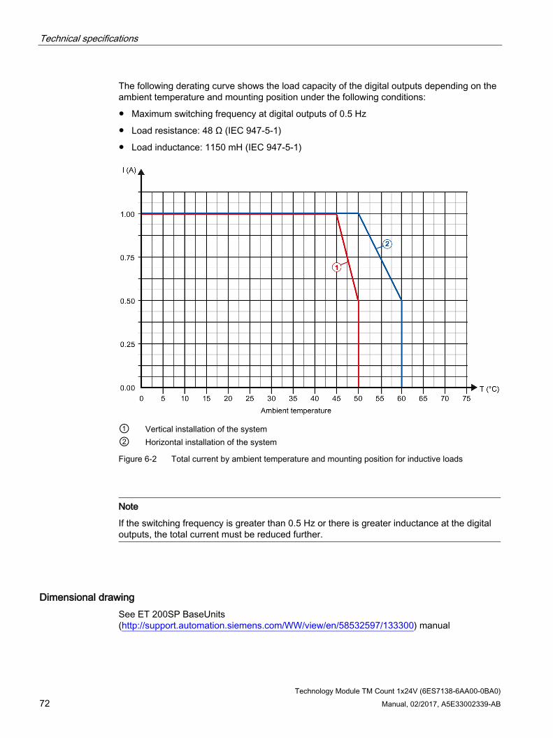
Technical specifications
Technology Module TM Count 1x24V (6ES7138-6AA00-0BA0) 72 Manual, 02/2017, A5E33002339-AB
The following derating curve shows the load capacity of the digital outputs depending on the ambient temperature and mounting position under the following conditions:
● Maximum switching frequency at digital outputs of 0.5 Hz
● Load resistance: 48 Ω (IEC 947-5-1)
● Load inductance: 1150 mH (IEC 947-5-1)
① Vertical installation of the system ② Horizontal installation of the system
Figure 6-2 Total current by ambient temperature and mounting position for inductive loads
Note
If the switching frequency is greater than 0.5 Hz or there is greater inductance at the digital outputs, the total current must be reduced further.
Dimensional drawing See ET 200SP BaseUnits (http://support.automation.siemens.com/WW/view/en/58532597/133300) manual
Technology Module TM Count 1x24V (6ES7138-6AA00-0BA0) 73 Manual, 02/2017, A5E33002339-AB
Parameter data record A A.1 Parameter assignment and structure of the parameter data record
You have the option of reassigning module parameters with the user program while the CPU is in RUN. The parameters are transferred to the module using data record 128, for example with the WRREC instruction.
If errors occur during the transfer or validation of parameters with the WRREC instruction, the module continues operation with the previous parameter assignment. A corresponding error code is then written to the STATUS output parameter. If no errors occur, the STATUS output parameter contains the length of the actually transferred data.
The description of the WRREC instruction and the error codes is available in section Parameter validation error (Page 81) or in the online help of STEP 7 (TIA Portal).
Structure of data record 128 The table below shows you the structure of data record 128 for TM Count 1x24V with 1 channel. The values in byte 0 to byte 3 are fixed and may not be changed. The value in byte 4 can only be changed by means of new parameter assignment and not in RUN mode.
Note
After each writing of data record 128, the module is set to its startup state and the counter value is set to the start value. If Reaction to CPU STOP "Continue operation" is set, the module is only set to its startup state when data record 128 has been changed.
Table A- 1 Parameter data record 128
Bit → Bit 7
Bit 6
Bit 5
Bit 4
Bit 3
Bit 2
Bit 1
Bit 0 Byte ↓
0...3 Header 0 Major Version = 0 Minor Version = 1 1 Length of the parameter data = 48 2 Reserved2) 3 Reserved2)

Parameter data record A.1 Parameter assignment and structure of the parameter data record
Technology Module TM Count 1x24V (6ES7138-6AA00-0BA0) 74 Manual, 02/2017, A5E33002339-AB
Bit → Bit 7
Bit 6
Bit 5
Bit 4
Bit 3
Bit 2
Bit 1
Bit 0 Byte ↓
4...51 Counting channel 4 Operating mode 4 Reserved2) Operating mode:
0000B: Reserved 0001B: Counting 0010B: Measuring 0011 to 1111B: Invalid
5 Basic parameters 5 Reserved2) Enable
additional diagnostic interrupts1)
Reaction to CPU STOP: 00B: Output substitute value 01B: Keep last value 10B: Continue operation 11B: Invalid
6...7 Counter inputs 6 Sensor type: Signal evaluation: Signal type:
00B: Sourcing output 00B: Single 0000B: Pulse (A) 01B: Sinking output 01B: Double 0001B: Pulse (A) and direction (B) 10B: Push-pull (sinking and sourcing output)
10B: Quadruple 0010B: Count up (A), count down (B)
11B: Invalid 11B: Invalid 0011B: Incremental encoder (A, B phase-shifted) 0100B: Incremental encoder (A, B, N)
0101 to 1111B: Invalid 7 Reaction to signal N: Invert direc-
tion1) Enable diagnostics interrupt at wire break1)
Filter frequency: 00B: No reaction to sig-nal N
0000B: 100 Hz 0001B: 200 Hz
01B: Synchronization at signal N
0010B: 500 Hz 0011B: 1 kHz
10B: Capture at signal N 0100B: 2 kHz 11B: Invalid 0101B: 5 kHz 0110B: 10 kHz
0111B: 20 kHz 1000B: 50 kHz 1001B: 100 kHz 1010B: 200 kHz 1011 to 1111B: Invalid

Parameter data record A.1 Parameter assignment and structure of the parameter data record
Technology Module TM Count 1x24V (6ES7138-6AA00-0BA0) Manual, 02/2017, A5E33002339-AB 75
Bit → Bit 7
Bit 6
Bit 5
Bit 4
Bit 3
Bit 2
Bit 1
Bit 0 Byte ↓
8...9 Hardware interrupts1) 8 Reserved2) Change of
direction Underflow (low count-ing limit violated)
Overflow (high count-ing limit violated)
Gate stop Gate start
9 Synchroni-zation of the counter by an external signal
New Cap-ture value available
Reserved2) Zero pass Reserved2) Comparison event for DQ1 has occurred
Reserved2) Comparison event for DQ0 has occurred
10...15 Behavior of DQ0/1 10 Set output (DQ1): Set output (DQ0):
0000B: Use by user program 0000B: Use by user program 0001B: Between comparison value and high limit; measuring: measured value >= comparison value
0001B: Between comparison value and high limit; measuring: measured value >= comparison value
0010B: Between comparison value and low limit; measuring: measured value <= comparison value
0010B: Between comparison value and low limit; meas-uring: measured value <= comparison value
0011B: At comparison value for a pulse duration 0011B: At comparison value for a pulse duration 0100B: Between comparison value 0 and 1 0100B: Invalid 0101B: After set command from CPU until comparison value
0101B: After set command from CPU until comparison value
0110B: Not between comparison value 0 and 1 0110 to 1111B: Invalid 0111 to 1111B: Invalid
11 Count direction (DQ1): Count direction (DQ0): Reserved2) Substitute value for DQ1
Substitute value for DQ0
00B: Invalid 00B: Invalid 01B: Forward 01B: Forward 10B: Backward 10B: Backward 11B: In both directions 11B: In both directions
12 Pulse duration (DQ0): WORD: Value range in ms/10: 0 to 65535D 13
14 Pulse duration (DQ1): WORD: Value range in ms/10: 0 to 65535D 15

Parameter data record A.1 Parameter assignment and structure of the parameter data record
Technology Module TM Count 1x24V (6ES7138-6AA00-0BA0) 76 Manual, 02/2017, A5E33002339-AB
Bit → Bit 7
Bit 6
Bit 5
Bit 4
Bit 3
Bit 2
Bit 1
Bit 0 Byte ↓
16 Behavior of DI0 16 Behavior of
counter value after Capture (DI0):
Edge selection (DI0): Select level (DI0):
Reserved2) Set function of DI (DI0): 00B: Invalid 000B: Gate start/stop (level-triggered) 01B: At rising edge 0B: Active
with high level
001B: Gate start (edge-triggered) 10B: At falling edge 010B: Gate stop (edge-triggered)
0B: Contin-ue counting
11B: At rising and falling edge
1B: Active with low level
011B: Synchronization 100B: Enable synchronization at signal N
1B: Set to start value and contin-ue counting
101B: Capture 110B: Digital input without function 111B: Invalid
17 Behavior of DI1: See Byte 16
18 Behavior of DI2: See Byte 16
19 Frequency: Reserved2) Input delay: 0B: Once 0000B: None
0001B: 0.05 ms 1B: Periodic 0010B: 0.1 ms
0011B: 0.4 ms 0100B: 0.8 ms
0101B: 1.6 ms 0110B: 3.2 ms 0111B: 12.8 ms 1000B: 20 ms 1001 to 1111B: Invalid
20...43 Values 20...23 High counting limit:
DWORD: Value range: –2147483648 to 2147483647D or 80000000 to 7FFFFFFFH 24...27 Comparison value 0:
Counting mode: DWORD: Value range: –2147483648 to 2147483647D or 80000000 to 7FFFFFFFH; Measuring mode: REAL: Floating point number in the configured unit of the measured variable
28...31 Comparison value 1: Counting mode: DWORD: Value range: –2147483648 to 2147483647D: or 80000000 to 7FFFFFFFH;
Measuring mode: REAL: Floating point number in the configured unit of the measured variable 32...35 Start value:
DWORD: Value range: –2147483648 to 2147483647D or 80000000 to 7FFFFFFFH 36...39 Low counting limit:
DWORD: Value range: –2147483648 to 2147483647D or 80000000 to 7FFFFFFFH 40...43 Update time:
DWORD: Value range in μs: 0 to 25000000D
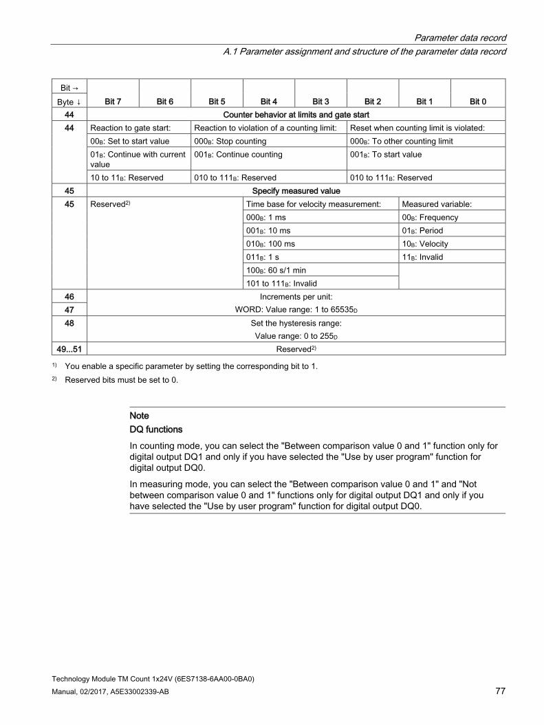
Parameter data record A.1 Parameter assignment and structure of the parameter data record
Technology Module TM Count 1x24V (6ES7138-6AA00-0BA0) Manual, 02/2017, A5E33002339-AB 77
Bit → Bit 7
Bit 6
Bit 5
Bit 4
Bit 3
Bit 2
Bit 1
Bit 0 Byte ↓
44 Counter behavior at limits and gate start 44 Reaction to gate start: Reaction to violation of a counting limit: Reset when counting limit is violated:
00B: Set to start value 000B: Stop counting 000B: To other counting limit 01B: Continue with current value
001B: Continue counting 001B: To start value
10 to 11B: Reserved 010 to 111B: Reserved 010 to 111B: Reserved 45 Specify measured value 45 Reserved2) Time base for velocity measurement: Measured variable:
000B: 1 ms 00B: Frequency 001B: 10 ms 01B: Period 010B: 100 ms 10B: Velocity 011B: 1 s 11B: Invalid 100B: 60 s/1 min 101 to 111B: Invalid
46 Increments per unit: WORD: Value range: 1 to 65535D 47
48 Set the hysteresis range: Value range: 0 to 255D
49...51 Reserved2) 1) You enable a specific parameter by setting the corresponding bit to 1.
2) Reserved bits must be set to 0.
Note DQ functions
In counting mode, you can select the "Between comparison value 0 and 1" function only for digital output DQ1 and only if you have selected the "Use by user program" function for digital output DQ0.
In measuring mode, you can select the "Between comparison value 0 and 1" and "Not between comparison value 0 and 1" functions only for digital output DQ1 and only if you have selected the "Use by user program" function for digital output DQ0.
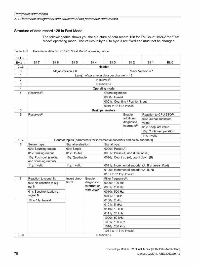
Parameter data record A.1 Parameter assignment and structure of the parameter data record
Technology Module TM Count 1x24V (6ES7138-6AA00-0BA0) 78 Manual, 02/2017, A5E33002339-AB
Structure of data record 128 in Fast Mode The following table shows you the structure of data record 128 for TM Count 1x24V for "Fast Mode" operating mode. The values in byte 0 to byte 3 are fixed and must not be changed.
Table A- 2 Parameter data record 128: "Fast Mode" operating mode
Bit → Bit 7
Bit 6
Bit 5
Bit 4
Bit 3
Bit 2
Bit 1
Bit 0 Byte ↓
0...3 Header 0 Major Version = 0 Minor Version = 1 1 Length of parameter data per channel = 48 2 Reserved2) 3 Reserved2) 4 Operating mode 4 Reserved2) Operating mode:
0000B: Invalid 0001B: Counting / Position input 0010 to 1111B: Invalid
5 Basic parameters 5 Reserved2) Enable
additional diagnostic interrupts1)
Reaction to CPU STOP: 00B: Output substitute value 01B: Keep last value 10B: Continue operation 11B: Invalid
6...7 Counter inputs (parameters for incremental encoders and pulse encoders) 6 Sensor type: Signal evaluation: Signal type:
00B: Sourcing output 00B: Single 0000B: Pulse (A) 01B: Sinking output 01B: Double 0001B: Pulse (A) and direction (B) 10B: Push-pull (sinking and sourcing output)
10B: Quadruple 0010B: Count up (A), count down (B)
11B: Invalid 11B: Invalid 0011B: Incremental encoder (A, B phase-shifted) 0100B: Incremental encoder (A, B, N)
0101 to 1111B: Invalid 7 Reaction to signal N: Invert direc-
tion1) Enable diagnostic interrupt on wire break1)
Filter frequency3): 00B: No reaction to sig-nal N
0000B: 100 Hz 0001B: 200 Hz
01B: Synchronization at signal N
0010B: 500 Hz 0011B: 1 kHz
10 to 11B: Invalid 0100B: 2 kHz 0101B: 5 kHz
0110B: 10 kHz 0111B: 20 kHz 1000B: 50 kHz 1001B: 100 kHz 1010B: 200 kHz 1011 to 1111B: Invalid
8...9 Reserved2)

Parameter data record A.1 Parameter assignment and structure of the parameter data record
Technology Module TM Count 1x24V (6ES7138-6AA00-0BA0) Manual, 02/2017, A5E33002339-AB 79
Bit → Bit 7
Bit 6
Bit 5
Bit 4
Bit 3
Bit 2
Bit 1
Bit 0 Byte ↓
10...15 Behavior of a DQ 10 Set output (DQ1): Set output (DQ0):
0000B: Digital output without function 0000B: Digital output without function 0001B: Between comparison value and high limit 0001B: Between comparison value and high limit 0010B: Between comparison value and low limit 0010B: Between comparison value and low limit 0011B: At comparison value for a pulse duration 0011B: At comparison value for a pulse duration 0100B: Between comparison value 0 and 1 0100B to 1111B: Invalid 0101 to 1111B: Invalid
11 Count direction (DQ1): Count direction (DQ0): Reserved2) Reserved2) Substitute value for DQ1
Substitute value for DQ0
00B: Reserved 00B: Reserved 01B: Up 01B: Up 10B: Down 10B: Down 11B: In both directions 11B: In both directions
12 Pulse duration (DQ0): UINT: Value range in ms/10: 0 to 65535D 13
14 Pulse duration (DQ1): UINT: Value range in ms/10: 0 to 65535D 15
16 Behavior of DI0 16 Reserved2) Edge selection (DI0): Select level
(DI0): Reserved2) Set function of DI (DI0):
00B: Invalid 000B: Gate start/stop (level-triggered) 01B: At rising edge 0B: Active
with high level
001B: Gate start (edge-triggered) 10B: At falling edge 010B: Gate stop (edge-triggered)
11B: Invalid 1B: Active with low level
011B: Synchronization3) 100B: Enable synchronization at signal N
101B: Invalid 110B: Digital input without function 111B: Invalid
17 Behavior of DI1: See Byte 16
18 Behavior of DI2: See Byte 16
19 Frequency: Count direction for syn-chronization
Reserved2) Input delay:
0B: Once 00B: Invalid 0000B: None 1B: Periodic 01B: Up 0001B: 0.05 ms 10B: Down 0010B: 0.1 ms
11B: In both directions 0011B: 0.4 ms 0100B: 0.8 ms
0101B: 1.6 ms 0110B: 3.2 ms 0111B: 12.8 ms 1000B: 20 ms 1001 to 1111B: Invalid
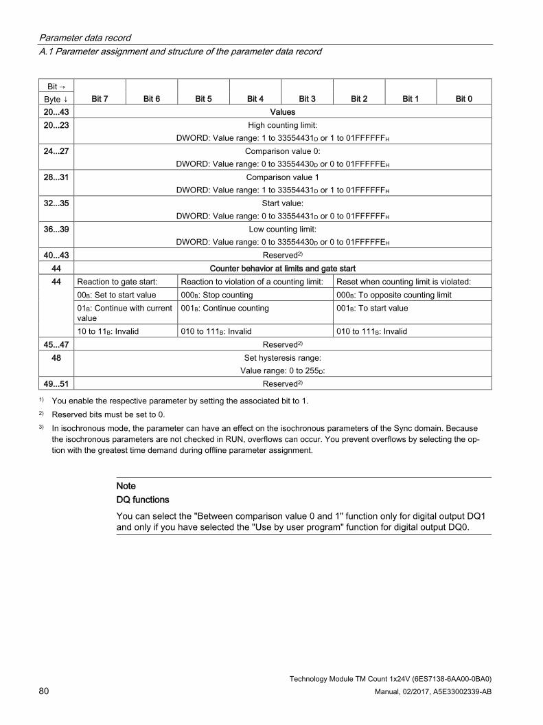
Parameter data record A.1 Parameter assignment and structure of the parameter data record
Technology Module TM Count 1x24V (6ES7138-6AA00-0BA0) 80 Manual, 02/2017, A5E33002339-AB
Bit → Bit 7
Bit 6
Bit 5
Bit 4
Bit 3
Bit 2
Bit 1
Bit 0 Byte ↓
20...43 Values 20...23 High counting limit:
DWORD: Value range: 1 to 33554431D or 1 to 01FFFFFFH 24...27 Comparison value 0:
DWORD: Value range: 0 to 33554430D or 0 to 01FFFFFEH 28...31 Comparison value 1
DWORD: Value range: 1 to 33554431D or 1 to 01FFFFFFH 32...35 Start value:
DWORD: Value range: 0 to 33554431D or 0 to 01FFFFFFH 36...39 Low counting limit:
DWORD: Value range: 0 to 33554430D or 0 to 01FFFFFEH 40...43 Reserved2)
44 Counter behavior at limits and gate start 44 Reaction to gate start: Reaction to violation of a counting limit: Reset when counting limit is violated:
00B: Set to start value 000B: Stop counting 000B: To opposite counting limit 01B: Continue with current value
001B: Continue counting 001B: To start value
10 to 11B: Invalid 010 to 111B: Invalid 010 to 111B: Invalid 45...47 Reserved2)
48 Set hysteresis range: Value range: 0 to 255D:
49...51 Reserved2) 1) You enable the respective parameter by setting the associated bit to 1.
2) Reserved bits must be set to 0. 3) In isochronous mode, the parameter can have an effect on the isochronous parameters of the Sync domain. Because
the isochronous parameters are not checked in RUN, overflows can occur. You prevent overflows by selecting the op-tion with the greatest time demand during offline parameter assignment.
Note DQ functions
You can select the "Between comparison value 0 and 1" function only for digital output DQ1 and only if you have selected the "Use by user program" function for digital output DQ0.

Parameter data record A.2 Parameter validation error
Technology Module TM Count 1x24V (6ES7138-6AA00-0BA0) Manual, 02/2017, A5E33002339-AB 81
A.2 Parameter validation error If you make the parameter settings in STEP 7 (TIA Portal) or in STEP 7 , the parameter values are checked before they are transferred to the technology module. This process prevents parameter errors.
In other use cases, the technology module checks the transferred parameter data record. If the technology module finds invalid or inconsistent parameter values, it outputs an error code (see below). The new parameter data record is rejected in this case, and work continues with the current parameter values until a valid parameter data record has been transferred.
WRREC When the CPU is in RUN, you can change the parameter data record with the instruction WRREC (Write Record). In case of errors, the WRREC instruction returns corresponding error codes in the STATUS parameter.
Example:
Let us assume that an invalid value, for example 9, is written to the module for the operating mode with WRREC. As a consequence, the module rejects the entire parameter data record. You can recognize this by evaluating the STATUS output parameter of the WRREC instruction. The STATUS output parameter is output as an ARRAY[1..4] of BYTE data with the value 16#DF80E111: Example of WRREC STATUS data
Address Meaning
DFH STATUS[1] Error when writing a data record via PROFINET IO (IEC 61158-6) 80H STATUS[2] Error when reading or writing a data record via PROFINET IO
(IEC 61158-6) E1H STATUS[3] Module-specific error 11H STATUS[4] Error code from the table below:
The "Operating mode" parameter has an invalid value.
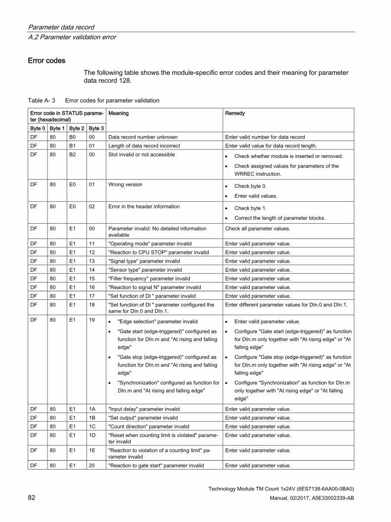
Parameter data record A.2 Parameter validation error
Technology Module TM Count 1x24V (6ES7138-6AA00-0BA0) 82 Manual, 02/2017, A5E33002339-AB
Error codes The following table shows the module-specific error codes and their meaning for parameter data record 128.
Table A- 3 Error codes for parameter validation
Error code in STATUS parame-ter (hexadecimal)
Meaning Remedy
Byte 0 Byte 1 Byte 2 Byte 3 DF 80 B0 00 Data record number unknown Enter valid number for data record DF 80 B1 01 Length of data record incorrect Enter valid value for data record length. DF 80 B2 00 Slot invalid or not accessible • Check whether module is inserted or removed.
• Check assigned values for parameters of the WRREC instruction.
DF 80 E0 01 Wrong version • Check byte 0.
• Enter valid values.
DF 80 E0 02 Error in the header information • Check byte 1.
• Correct the length of parameter blocks.
DF 80 E1 00 Parameter invalid: No detailed information available
Check all parameter values.
DF 80 E1 11 "Operating mode" parameter invalid Enter valid parameter value. DF 80 E1 12 "Reaction to CPU STOP" parameter invalid Enter valid parameter value. DF 80 E1 13 "Signal type" parameter invalid Enter valid parameter value. DF 80 E1 14 "Sensor type" parameter invalid Enter valid parameter value. DF 80 E1 15 "Filter frequency" parameter invalid Enter valid parameter value. DF 80 E1 16 "Reaction to signal N" parameter invalid Enter valid parameter value. DF 80 E1 17 "Set function of DI " parameter invalid Enter valid parameter value. DF 80 E1 18 "Set function of DI " parameter configured the
same for DIn.0 and DIn.1. Enter different parameter values for DIn.0 and DIn.1.
DF 80 E1 19 • "Edge selection" parameter invalid
• "Gate start (edge-triggered)" configured as function for DIn.m and "At rising and falling edge"
• "Gate stop (edge-triggered)" configured as function for DIn.m and "At rising and falling edge"
• "Synchronization" configured as function for DIn.m and "At rising and falling edge"
• Enter valid parameter value.
• Configure "Gate start (edge-triggered)" as function for DIn.m only together with "At rising edge" or "At falling edge"
• Configure "Gate stop (edge-triggered)" as function for DIn.m only together with "At rising edge" or "At falling edge"
• Configure "Synchronization" as function for DIn.m only together with "At rising edge" or "At falling edge"
DF 80 E1 1A "Input delay" parameter invalid Enter valid parameter value. DF 80 E1 1B "Set output" parameter invalid Enter valid parameter value. DF 80 E1 1C "Count direction" parameter invalid Enter valid parameter value. DF 80 E1 1D "Reset when counting limit is violated" parame-
ter invalid Enter valid parameter value.
DF 80 E1 1E "Reaction to violation of a counting limit" pa-rameter invalid
Enter valid parameter value.
DF 80 E1 20 "Reaction to gate start" parameter invalid Enter valid parameter value.

Parameter data record A.2 Parameter validation error
Technology Module TM Count 1x24V (6ES7138-6AA00-0BA0) Manual, 02/2017, A5E33002339-AB 83
Error code in STATUS parame-ter (hexadecimal)
Meaning Remedy
Byte 0 Byte 1 Byte 2 Byte 3 DF 80 E1 211 • Low counting limit > comparison value 0
• Low counting limit > comparison value 1
• Low counting limit < comparison value 0
• Low counting limit < comparison value 1
DF 80 E1 221 • High counting limit > comparison value 0
• High counting limit > comparison value 1
• High counting limit < comparison value 0
• High counting limit < comparison value 1
DF 80 E1 23 • "Start value" parameter invalid
• "Low counting limit" parameter invalid
Enter valid parameter value: Start value > low counting limit
DF 80 E1 24 • "Start value" parameter invalid
• "High counting limit" parameter invalid
Enter valid parameter value: Start value < high counting limit
DF 80 E1 25 "Update time" parameter invalid Enter parameter value from range 0 to 25000000D. DF 80 E1 262 "Reference speed" parameter invalid Enter parameter value from range 6.00 to
210000.00D. DF 80 E1 27 "Measured variable" parameter invalid Enter valid parameter value. DF 80 E1 28 "Time base for velocity measurement" parame-
ter invalid Enter valid parameter value.
DF 80 E1 29 "Increments per unit" parameter invalid Enter valid parameter value. DF 80 E1 2A • "High counting limit" parameter invalid
• "Low counting limit" parameter invalid
Enter valid parameter value: Low counting limit < high counting limit
DF 80 E1 2B • "Comparison value 0" parameter invalid
• "Comparison value 1" parameter invalid
Enter valid parameter value: Comparison value 0 < comparison value 1
DF 80 E1 2C "Signal evaluation" parameter invalid Enter valid parameter value. DF 80 E1 2D • "Between comparison value 0 and 1" con-
figured for DQn.0
• "Not between comparison value 0 and 1" configured for DQn.0
• "Between comparison value 0 and 1" con-figured for DQn.1, but "Use by user pro-gram" not configured for DQn.0
• "Not between comparison value 0 and 1" configured for DQn.1, but "Use by user pro-gram" not configured for DQn.0
• Configure "Between comparison value 0 and 1" only for DQn.1
• Configure "Not between comparison value 0 and 1" only for DQn.1
• Only configure "Between comparison value 0 and 1" for DQn.1, when "Use by user program" is configured for DQn.0
• Only configure "Not between comparison value 0 and 1" for DQn.1, when "Use by user program" is configured for DQn.0
DF 80 E1 2E "Capture" configured for DIn.m in "Measuring" operating mode
Do not configure "Capture" for DIn.m in "Measuring" operating mode.
DF 80 E1 3A3 "Count direction for synchronization" parameter invalid
Enter valid parameter value.
1 Only for "Counting" operating mode 2 Only for "Position input for technology object "Motion Control"" operating mode 3 Only for "Fast Mode" operating mode


