Survivable Virtual Network Redesign and
Embedding in Cloud Data Center Networks
Yiheng Chen
A Thesis
in
The Department
of
Concordia Institute for
Information
Systems Engineering
Presented in Partial Fulfillment of the
Requirements for the Degree of Master of Applied
Science (Information System Security) at Concordia
University
Montreal, Quebec, Canada
February 2015
© Yiheng Chen, 2015


ABSTRACT
Survivable Virtual Network Redesign and Embedding in
Cloud Data Center Networks
Yiheng Chen
Today, the cloud computing paradigm enables multiple virtualized services to co-exist on
the same physical machine and share the same physical resources, hardware, as well as energy
consumption expenses. To allow cloud customers migrate their services on to the cloud side, the
Infrastructure Provider (InP) or cloud data centre operator provisions to its tenants virtual
networks (VNs) to host their services. Virtual Networks can be thought of as segmenting the
physical network and its resources, and such VN requests (or tenants) need to be mapped onto
the substrate network and provisioned with sufficient physical resources as per the users'
requirements. With this emerging computing paradigm, cloud customers may demand to have
highly reliable services for the hosted applications; however, failures often happen unexpectedly
in data-centers, interrupting critical cloud services. Consequently, VN or cloud services are
provisioned with redundant resources to achieve the demanded level of service reliability. To
maintain a profitable operation of their network and resources, and thus achieve increased long
term revenues, cloud network operators often rely on optimizing the mapping of reliable cloud
services. Such problem is referred to as in the literature as "Survivable Virtual Network
Embedding (SVNE) '' problem. In this thesis, the survivable VN embedding problem is studied
and a novel cost-efficient Survivable Virtual Network Redesign algorithm is carefully designed,
presented, and evaluated. Subsequently, we distinguish between the communication services
provided by the cloud provider and study the problem of survivable embedding of multicast
services; we formally model the problem, and present two algorithms to reactively maintain
multicast trees in cloud data centers upon failures.
iii

Contents
List of Figures
Abbreviations
iv
1 Introduction 1
1.1 Background and Motivation . . . . . . . . . . . . . . . . . . . . . . 1
1.1.1 Problem Definitions . . . . . . . . . . . . . . . . . . . . . . . 4
1.1.2 Reasoning and Optimizations . . . . . . . . . . . . . . . . . 5
1.2 Thesis Organization . . . . . . . . . . . . . . . . . . . . . . . . . . . 7
2 Preliminaries and Related Work 8
2.1 Failure Senarios and Protection Methods . . . . . . . . . . . . . . . 8
2.1.1 Type of Failures . . . . . . . . . . . . . . . . . . . . . . . . . 8
2.1.2 Protection Methods . . . . . . . . . . . . . . . . . . . . . . . 9
2.2 Virtual Network Redesign and Embedding . . . . . . . . . . . . . . 10
2.2.1 Related Work on Virtual Network Redesign and Embedding 11
2.2.2 Virtual Network Redesign Solutions and limitations . . . . . 14
2.2.3 Resource Sharing techniques . . . . . . . . . . . . . . . . . . 16
2.3 Multicast Virtual Network . . . . . . . . . . . . . . . . . . . . . . . 19
3 Survivable Virtual Network Redesign and Embedding 22
3.1 Introduction . . . . . . . . . . . . . . . . . . . . . . . . . . . . . . . 22
3.2 Problem Definition . . . . . . . . . . . . . . . . . . . . . . . . . . . 25
3.3 The SVN Redesign Problem . . . . . . . . . . . . . . . . . . . . . . 28
3.3.1 Limitations of Conventional VN Redesign Techniques . . . . 28
3.3.2 Illustrative Example . . . . . . . . . . . . . . . . . . . . . . 31
3.4 Prognostic Redesign Approach (Pro-Red) : . . . . . . . . . . . . . . 33
3.4.1 Theoretical Foundation . . . . . . . . . . . . . . . . . . . . . 33
3.4.2 Pro-Red Algorithm : . . . . . . . . . . . . . . . . . . . . . . 36
3.5 The SVN Embedding . . . . . . . . . . . . . . . . . . . . . . . . . . 41
3.6 Numerical Results . . . . . . . . . . . . . . . . . . . . . . . . . . . . 44
3.7 Conclusion . . . . . . . . . . . . . . . . . . . . . . . . . . . . . . . . 48
4 Post-Failure Restoration for Multicast Services in Data CenterNetworks 50
4.1 Introduction . . . . . . . . . . . . . . . . . . . . . . . . . . . . . . . 50
v
iv

4.2 Network Model and Problem Description . . . . . . . . . . . . . . . 51
4.2.1 Network Model . . . . . . . . . . . . . . . . . . . . . . . . . 51
4.2.2 Understanding the impact of failure on MVNs . . . . . . . . 54
4.2.3 The MVN Restoration Problem . . . . . . . . . . . . . . . . 57
4.2.3.1 Problem Formulation . . . . . . . . . . . . . . . . . 57
4.2.3.2 Complexity Analysis . . . . . . . . . . . . . . . . . 60
4.3 Path-Convergence Method for finding a backup source . . . . . . . 61
4.4 Hop-to-Hop Terminal Finding Algorithm . . . . . . . . . . . . . . . 63
4.5 Numerical Results . . . . . . . . . . . . . . . . . . . . . . . . . . . . 66
4.6 Conclusion . . . . . . . . . . . . . . . . . . . . . . . . . . . . . . . . 68
5 Conclusion and Future Work 70
5.1 Conclusion . . . . . . . . . . . . . . . . . . . . . . . . . . . . . . . . 70
5.2 Contributions . . . . . . . . . . . . . . . . . . . . . . . . . . . . . . 71
5.3 Future Work . . . . . . . . . . . . . . . . . . . . . . . . . . . . . . . 72
Bibliography 74
v

List of Figures
1.1 Virtual Network Embedding Problem . . . . . . . . . . . . . . . . . 4
2.1 Failure in the Substrate Network . . . . . . . . . . . . . . . . . . . 9
2.2 Survivable Virual Network Redesign Schemes . . . . . . . . . . . . 11
2.3 Resource Sharing techniques in SVN embedding phrase . . . . . . . 17
3.1 Substrate Network and Virtual Network Representation . . . . . . . 26
3.2 Designing and Embedding Reliable VNs . . . . . . . . . . . . . . . 29
3.3 Theoretical Foundation . . . . . . . . . . . . . . . . . . . . . . . . . 33
3.4 Designing Reliable VNs . . . . . . . . . . . . . . . . . . . . . . . . . 35
3.5 Step-by-Step SVN Redesign Algorithm. . . . . . . . . . . . . . . . . 40
3.6 Comparison between Pro-Red, 1-Redundant and K-Redundant Scheme. 49
4.1 Network Model . . . . . . . . . . . . . . . . . . . . . . . . . . . . . 51
4.2 Impact of a Substrate Node or Physical Link Failure . . . . . . . . 55
4.3 Muticast VN Maintenance Approaches Comparision Test Results . 69
5.1 Advantage of Terminal Nodes Migration . . . . . . . . . . . . . . . 73
vi
Abbreviations
BG - Backup Group
DFS - Distribyted File-Systems
DVBMT - Delay- and Delay-Variation Bounded Multicast Tree
FDP - Failure Dependent Protection
FIP - Failure Independent Protection
HPC - High Performance Computing
IaaS - Infrastructure as a Service
InP - Infrastructure Provider
MVN - Multicast Virtual Network
NP-hard - Non-deterministic Polynomial-time hard
PaaS - Platform as a Service
QoS - Quality of Service
SaaS - Software as a Service
SDN - Software Define Network
SLA - Service Level Agreement
SMVN - Survivable Multicast Virtual Network
SMVNE - Survivable Multicast Virtual Network Embedding
SP - Service Provider
SVN - Survivable Virtual Network
VDC - Virtual Data Center
VL - Virtual Link
VM - Virtual Machine
VN - Virtual Network
VNE - Virtual Network Embedding
vii

WG - Working Group
viii

Chapter 1
Introduction
1.1 Background and Motivation
The Internet has made significant impact on our society, business models and our
daily lives. As a new paradigm for the future Internet, cloud computing has drawn
the attention of the general public in recent years. In simple terms, cloud com-
puting is capable to create a virtual environment which allows both software and
hardware to be shared by multiple-users via the Internet. With cloud computing,
businesses are no longer required to incur investment on purchasing hardware and
software licenses in order to deploy their services and applications. Moreover, hu-
man expenses can also be reduced since the operating and maintaining cost will
be shifted to the cloud side [1].
Today, there are two main players in the cloud computing market; namely, the
Service Provider (SP) and the Infrastructure Provider (InP). The former allows
cloud users access to the cloud service via the Internet; whereas, the latter man-
ages infrastructures and leases physical resources to SP [2]. According to the type
of services, cloud service scenarios can be classified into three main types: Infras-
tructure as a Service (IaaS), in which the InPs split their resources and outsource
1
them to the SPs; for instance Amazon EC2 and Microsoft Azure are the appli-
cations that would provide such service. Platform as a Service (PaaS), it offers
a framework which systems users can build on, such as Google Apps Engine [2].
Last but not least, Software as a service (SaaS); instead of purchasing applica-
tions running them locally, SaaS allows a software to be shared among users via
the Internet; an example is GRIDS Lab Aneka[3]. In this thesis, a role of InP is
assumed, and IaaS services, precisely Virtual Network (VN) service, are served to
SPs based on their demands.
The InP provides an environment that allows Virtual Machines(VM) coexist on
the same physical machine. Through a VMs management software “Hypervisor”,
the InP is able to create, run and allocate resources for VMs. By sharing infras-
tructures, the operating cost and hardware investment can be greatly reduced.
VMs demand a minimum level of hardware specifications, typically in terms of
CPU capacity, memory, disk space, etc. In order to host multiple VMs in one
server, the server has to have sufficient physical resources. We address the VM
placement action as “Virtual Machine Embedding”. In addition, cloud customers
may migrate their network services to the cloud, thus Virtual Networks(VNs) need
to be embedded with more requirements on bandwidth, delay and so on. Hence,
the placement of VN becomes critical as good mapping solutions may cost less and
result in better service admissibility in a data center. Accordingly, it is important
for cloud vendors to optimize the placement of services to improve their revenue.
The optimal placement of cloud services, referred as “Virtual Network Embedding
(VNE)”, is known to be -Hard [4].
Now, cloud users may deploy certain critical services on the resources they leased,
but the hosting servers may break down for a variety of reasons. When they do
,VNs would get disconnected and the services would be disrupted. Hence, it is
very important for cloud vendors to provide certain degree of reliability to their
hosted VNs in the datacenter. In fact, most of the major cloud sevice provider
gaurantee their customers a certain level of QoS (Quality of Service), donoted as
2
“Service Level Agreement (SLA)”[5]. For example, Microsoft Azure promises its
users 99.9% availability of their virtualized services. To obtain such highly reli-
able service level, certain level of resource redundancy is required. The problem
of embedding a virtualized service with reliability is referred as “Survivable Vir-
tual Network Embedding (SVNE)”. There are two common failure scenarios in a
cloud datacenter: Substrate node failure and substrate link failure. In both cases,
redundancy needs to be provided in order to restore the failed services. Similar
to working resources, the redundant resources also need to be mapped onto the
substrate network, either before or after a failure; we call former “proactive protec-
tion”, as it reserves resources to be ready for for future failures; and we refer the
latter “reactive restoration”, since it finds alternative mapping solutions to restore
the VN services after a failure. Indeed, the mapping of redundant resources would
complicate the problem.
There are many SVNE solutions proposed by recent research papers; depending
on the failures considered, some work focus on the failure of physical links[6–9],
whereas others tackle the problem of node failures[10–17]; In this thesis, only fa-
cility node (servers for example) failures are considered, the reasons are two folds:
On one hand, link failures have been addressed in plenty of literatures, and the
techniques introduced can be reused in the light of network virtualization; On the
other hand, node failures effect the virtualized services running on the failed server
directly, thus triggering VM migration to re-place those VMs and the correspond-
ing virtual links must be re-mapped to resume the service. This is a variation of
VNE problem, thus it is also considered to be NP-hard. Moreover, some work
have been done to solve the SVNE problem in case of facility node failures in
the substrate network. In [10, 16, 18–22] node mapping and link mapping meth-
ods are developed for embedding a reliable-virtual-network, the resource sharing
techniques are explored to reduce the cost for embedding redundant resources.
However, in those work, redesigning survivable virtual network has never received
enough attention; though in [11] [12], backup resources are augmented only when
the overall availability does not meet the requirement, nonetheless cost efficient
3

is never considered for SVN redesign. Therefore, a technique is needed to design
VN requests, taking sharing of resources into account, and output a survivable
VN that can be embedded with least cost. In the first part of the thesis, a cost-
efficient-oriented survivable virtual network redesign algorithm is proposed, which
designs a VN request at virtual level, considering the future resource sharing in
the embedding phase. In the second part of this thesis, we address the problem of
Multicast Virtual Network (MVN) failures, and a novel reactive protection method
is developed to protect the embeded MVNs from node failures.
1.1.1 Problem Definitions
(a) Non-Survivable Virual Network (b) Substrate Network
Figure 1.1: Virtual Network Embedding Problem
The Substrate Network : We represent the substrate network as an undirected
graph denoted by Gs = (N ,L), where N is the set of substrate facility nodes, and
L is the set of substrate links. Facility nodes are connected to the network via
network nodes (routers/switches). Each substrate facility node n ∈ N is associated
with a finite computing capacity, denoted by cn. Similarly, each substrate link l
∈ L has a finite bandwidth capacity, denoted by dl. Figure 1.1(b) illustrates a
substrate network with 6 facility nodes, each with a CPU capacity varying from
2-10 units (represented by the number in parenthesis above each facility node).
Similarly, bandwidth on the substrate links interconnecting the network nodes
4
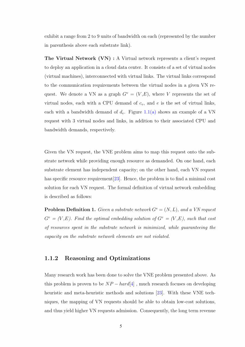
exhibit a range from 2 to 9 units of bandwidth on each (represented by the number
in parenthesis above each substrate link).
The Virtual Network (VN) : A Virtual network represents a client’s request
to deploy an application in a cloud data center. It consists of a set of virtual nodes
(virtual machines), interconnected with virtual links. The virtual links correspond
to the communication requirements between the virtual nodes in a given VN re-
quest. We denote a VN as a graph Gv = (V ,E), where V represents the set of
virtual nodes, each with a CPU demand of cv, and e is the set of virtual links,
each with a bandwidth demand of de. Figure 1.1(a) shows an example of a VN
request with 3 virtual nodes and links, in addition to their associated CPU and
bandwidth demands, respectively.
Given the VN request, the VNE problem aims to map this request onto the sub-
strate network while providing enough resource as demanded. On one hand, each
substrate element has independent capacity; on the other hand, each VN request
has specific resource requirement[23]. Hence, the problem is to find a minimal cost
solution for each VN request. The formal definition of virtual network embedding
is described as follows:
Problem Definition 1. Given a substrate network Gs = (N,L), and a VN request
Gv = (V ,E). Find the optimal embedding solution of Gv = (V ,E), such that cost
of resources spent in the substrate network is minimized, while guaranteeing the
capacity on the substrate network elements are not violated.
1.1.2 Reasoning and Optimizations
Many research work has been done to solve the VNE problem presented above. As
this problem is proven to be NP − hard[4] , much research focuses on developing
heuristic and meta-heuristic methods and solutions [23]. With these VNE tech-
niques, the mapping of VN requests should be able to obtain low-cost solutions,
and thus yield higher VN requests admission. Consequently, the long term revenue
5

is increased for InP, and the rental cost for VN customers can be lowered.
Today, most cloud vendors guarantee their users with high level of service avail-
ability; for instance, services that are hosted on Amazon EC2 are promised to
have 99.95 % availability; users can get 10% - 30% of their service credits back,
if the reliability level of their virtual services are violated. To achieve such high
level of service survivability, resource redundancy to virtualized services need to be
deployed at provisioning time or post-failure. On one hand, InPs are required to
deliver highly reliable VNs, thus redundancy must be deployed; on the other hand,
without a proper embedding technique, such redundancy may not be cost-efficient
[24]. Such problem is known as “Survivable Virtual Network Embedding”. As
SVNE problem can be divided into primary resource embedding and backup re-
source embedding, and the former alone is a NP −hard problem (virtual network
embedding problem), thus survivable virtual network embedding problem is even
harder to solve.
Numerous research work have attemptted to address the SVNE problem. Similar
to the VNE problem, most of the work relax it by solving the embedding in more
than one step. Moreover, mathmetical models [10–12, 16, 18–22] proposed but
most of them are either not scalable or non-linear. Consequently, heuristics[10,
12, 16, 18, 20] are introduced and acceptable solutions can be achieved.
In this thesis, we make two main contributions on SVNE problem, and are sum-
marized as the following:
• A cost-efficient SVN redesign algorithm is proposed to solve the survivable
VN redesign problem, and a mathmetical model is presented to embed a
given SVN assuming single facility node failures.
• We consider multicast cloud services and in particular present embedding
and maintenance techniques when such services are hosted by a cloud data
center.
6
1.2 Thesis Organization
The rest of this thesis is organized as follows. In Chapter 2, related background
knowledge are introduced; specifically, the type of failures in the cloud datacenter,
and corresponding protection methods. Also, each processing stage in SVNE is
discussed in this Chapter. The characterization of VNs are discussed at the end
of this Chapter. Chapter 3 studied the survivable VN redesign taking the sharing
techniques into account, a novel design method is proposed and compared against
conventional redesign schemes. Multicast virtual network is being considered in
Chapter 4, two multicast-tree maintance algorithms are designed to reactively
restore multicast VNs from node failures, while ensuring the delay constraints are
satisfied. Finally, conclusion and future work are presented in Chapter 5.
7

Chapter 2
Preliminaries and Related Work
2.1 Failure Senarios and Protection Methods
Fault-tolerance is a major concern of datacenter operators[25]. To protect virtu-
alized services from failures, failure senarios must be studied as well as the com-
monly deloyed countermeasures. In this subsection, the related work and recent
researches are surveyed.
2.1.1 Type of Failures
Both substrate links and substrate nodes may fail, and all virtualized services
that are running on top of them would be interupted. If a physical server fails,
all VMs that are being hosted on it will be shut down. Figure.2.1 illustrates how
a facility node (server) failure will affect the Virtual Machine (V1) running on top
of it. Similarly, the disconnection of a physical link may suspend all virtual links
that traverse through it. As shown in Fig.2.1, the physical link failure disconnects
the communication between VM V5 and V6. Therefore, we classify the substrate
failures as ”Link Failure” and ”Node Failure”, where the latter can be further
subdivided as ”Network Node Failure” and ”Facility Node Failure”[18]. ”Network
Nodes” usually refer to networking devices such as routers, switches, whereas
8

V1
V2
V3
V4
V6
V5
Facility Node Failure
Embedded virtual link connections
Network substrate
Cloud applicationsService A Service B
Embedded VN overlays(virtual DCS)
Network Node Failure
Link Failure
NetworkNode
Virtual facility node
Facilitynode
Legend
Substrate link Substrate Connection
Figure 2.1: Failure in the Substrate Network
”Facility Nodes” refer to servers that host virtual machines. In Fig.2.1, a failure
of a network node would terminate all the comunications which traverse through.
In terms of the scale of failures, there are ”Regional Failure”[26], which effect
multiple substrate elements, including nodes and links, at a time; and ”Signle
Failure”, which means only one substrate element outage, it can be either signle
server break down or single link disconnection. In this thesis, only a single facility
node failure is assumed.
2.1.2 Protection Methods
There are two main types of failure countermeasures, namely Protection and
Restoration[27]. Protection reserves backup resources proactively, the redundant
9

backup resources are always assigned before actual failure. These resources would
keep inactive until failure happens. On the other hand, restoration protects VNs
in a reactive manner. It is only activate after failure happens, and it is called on
demand to search for alternative mapping solution for the failed element(s).
In reactive approach, there is no redundancy provided, therefore, the embedding
cost of VNs that are running reactive restoration is definitely less than it of VNs
assigned with redundancy, hence it may allow substrate network to admit more
VN requests. However, upon failures, reactive approach does not gaurantee 100%
recovery of disrupted VNs, as it may not be able to find a feasible solution; whereas
proactively protected VNs can always be reconnected.
In terms of post-failure recovery capability, there are Failure Dependent Protec-
tion (FDP)[28, 29] and Failure Independent Protection (FIP)[10, 19–22]. In FIP,
each primary node will be assigned a specific backup node, such that upon failure
occurence, the primary can only be migrated to that backup host. In compari-
son, FDP allows working hosts to have different backup hosts in different failure
scenarios, and sometimes even working nodes are allowed to migrate [14]. In this
thesis, only FIP methods are considered.
2.2 Virtual Network Redesign and Embedding
In a typical Survivable Virtual Network Embedding solution, two design stages
are performed, namely ”reliable virtual network redesign” and ”survivable virtual
network embedding”. In the redesign stage, a given Virtual Network would be
augmented with redundant computational and bandwidth resources, such that
any facility node failure can be tolerated. The resulting graph is called ”Sur-
vivable Virtual Network”, and sometimes it is referred to ”Survivable Virtual
Infrastructure”[16]. In the embedding stage, the reliable-virtual-network from
the previous stage would be mapped onto the substrate network. While embed-
ding, it is important to make sure that the resources are shared and total cost is
minimized[18].
10
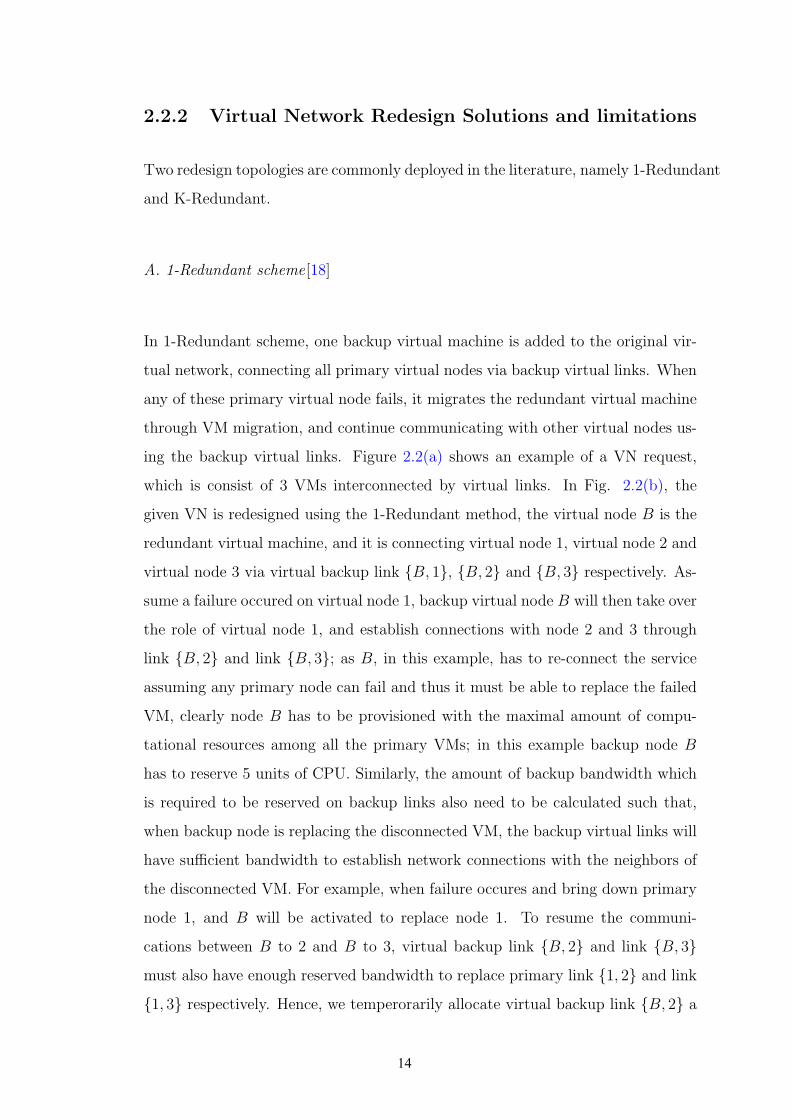
(a) Non-Survivable Virual Network (b) 1-Redundant SurvivableVirual Network
(c) K-Redundant Survivable Virual Network
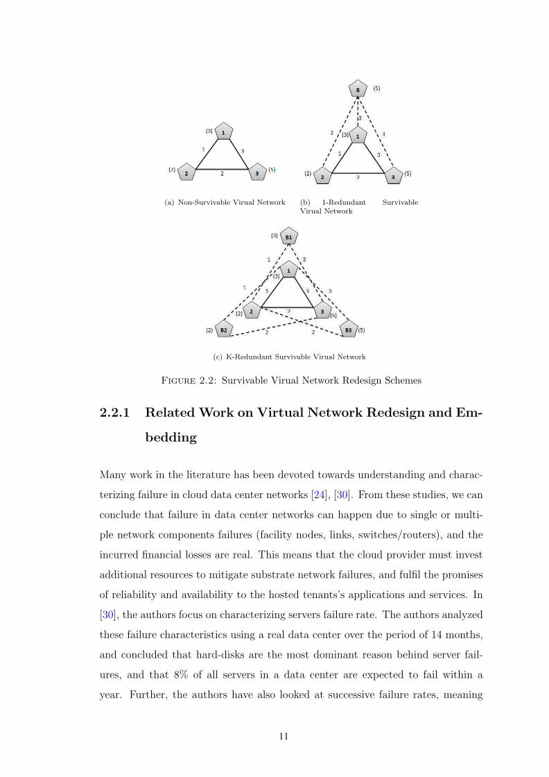
Figure 2.2: Survivable Virual Network Redesign Schemes
2.2.1 Related Work on Virtual Network Redesign and Em-
bedding
Many work in the literature has been devoted towards understanding and charac-
terizing failure in cloud data center networks [24], [30]. From these studies, we can
conclude that failure in data center networks can happen due to single or multi-
ple network components failures (facility nodes, links, switches/routers), and the
incurred financial losses are real. This means that the cloud provider must invest
additional resources to mitigate substrate network failures, and fulfil the promises
of reliability and availability to the hosted tenants’s applications and services. In
[30], the authors focus on characterizing servers failure rate. The authors analyzed
these failure characteristics using a real data center over the period of 14 months,
and concluded that hard-disks are the most dominant reason behind server fail-
ures, and that 8% of all servers in a data center are expected to fail within a
year. Further, the authors have also looked at successive failure rates, meaning
11

the probability that a failed server would fail again after repair, and it was found
that successive failure rates are quite high. For a 100 servers data center where
4 machines has failed more than once in 14 months; it was found that 20% of all
repeat failures happen within a day of the first failure; while 50% happen within
two weeks. Indeed, the estimated repair cost for a typical data center with more
than 100,000 servers is estimated in millions of dollars; not to mention the incurred
penalty cost due to affected services disruption.
In this regard, survivability against facility node failure is of paramount impor-
tance, particularly in the case of critical services that don’t tolerate failure. Indeed,
this problem has attracted significant attention from the literature; here we can
distinguish between single facility node failure [16], [18], [14], [15], and multiple
facility nodes failure [17], [13], [10]. In the case of single facility node failure, the
authors of [18] introduce a two-step approach to fully restore a VN from any single
facility node failure. Mainly, their approach consists of augmenting the VN request
with a 1-redundant or k-redundant backup nodes (where k represent the number
of critical nodes). The resultant SVN is then mapped onto the substrate network
by placing virtual nodes in a given VN on distinct substrate nodes, while aiming
to minimize the overall embedding cost. For this purpose, the authors introduce
two backup-sharing techniques to minimize the incurred backup-bandwidth cost,
namely cross-sharing and back-up sharing. The same problem is tackled in [16],
here the authors consider the SVN to be given, and their aim is to map the SVN
onto the substrate network while minimizing the amount of idle backup band-
width. The virtual nodes in a given VN maybe be mapped on the same substrate
nodes, as long as their corresponding backup nodes are mapped on distinct nodes;
this guarantees survivability against any single facility node failure. To embed
the SVN onto the substrate network, two embedding heuristics are presented: A
disjoint and a coordinated virtual node and virtual link mapping. For the disjoint
embedding approach, a set of feasible node mapping solutions is first enumerated,
then this set is passed on to an ILP model that picks the node mapping solution
with the lowest reserved backup bandwidth, while the coordinated embedding
12
adopts a link packing approach. Further, in [14], the authors present a novel ap-
proach for redesigning an SVN, denoted as Enhanced VN (EVN), and distinguish
between failure-dependent and failure-independent EVN. The failure-independent
EVN is similar to the 1-redundant SVN, while the failure-dependent EVN aims
at minimizing the amount of idle backup resources by relaxing the constraint that
only failed nodes will migrate. Instead, for each different failure-event, virtual
nodes (primaries and backups) within a given VN will be re-arranged (migrated)
differently to resume a working VN. Note that such approach incurs a consider-
able amount of migration overhead that can potentially cause a longer down-time.
Moreover, in [15] the authors also adopt the 1-redundant SVN scheme to create an
Auxiliary Protection Graph (APG). The APG is next embedded onto the substrate
network using a tabu-search meta-heuristic with cross-sharing and backup-sharing
to minimize the backup footprints.
As for survivability against multiple facility node failure [17], [13], [10], the VN
is augmented with the minimum number of backup nodes needed to guarantee a
reliability degree r under a given probability of failure p. Further, in [17] and [10],
the authors employ sharing across VNs in order to circumvent the inconvenience
of idle resources. As for [13], the authors employ survivability at the inter-data
center level, where a local protection approach is introduced to eliminate backup
bandwidth over wide-area network.
Equal effort has been devoted towards inaugurating effective protection schemes
against substrate link failures [6], [22], [7], [21]. Here protection schemes can be
mainly categorized as link-based and path-based protection. Further, few work in
the literature tackled the case of correlated failure [31], [32], that is the case of
single ”regional” failure that brings down multiple substrate nodes and links at
the same time. Substrate nodes and links that fail together are also referred to as
”shared risk group”. Here risk groups are considered to be given and protection
schemes are tailored for the case of a single risk group (regional) failure. A thor-
ough taxonomy of the various failure scenarios and existing protection methods
can be found in [33].
13
2.2.2 Virtual Network Redesign Solutions and limitations
Two redesign topologies are commonly deployed in the literature, namely 1-Redundant
and K-Redundant.
A. 1-Redundant scheme[18]
In 1-Redundant scheme, one backup virtual machine is added to the original vir-
tual network, connecting all primary virtual nodes via backup virtual links. When
any of these primary virtual node fails, it migrates the redundant virtual machine
through VM migration, and continue communicating with other virtual nodes us-
ing the backup virtual links. Figure 2.2(a) shows an example of a VN request,
which is consist of 3 VMs interconnected by virtual links. In Fig. 2.2(b), the
given VN is redesigned using the 1-Redundant method, the virtual node B is the
redundant virtual machine, and it is connecting virtual node 1, virtual node 2 and
virtual node 3 via virtual backup link {B, 1}, {B, 2} and {B, 3} respectively. As-
sume a failure occured on virtual node 1, backup virtual node B will then take over
the role of virtual node 1, and establish connections with node 2 and 3 through
link {B, 2} and link {B, 3}; as B, in this example, has to re-connect the service
assuming any primary node can fail and thus it must be able to replace the failed
VM, clearly node B has to be provisioned with the maximal amount of compu-
tational resources among all the primary VMs; in this example backup node B
has to reserve 5 units of CPU. Similarly, the amount of backup bandwidth which
is required to be reserved on backup links also need to be calculated such that,
when backup node is replacing the disconnected VM, the backup virtual links will
have sufficient bandwidth to establish network connections with the neighbors of
the disconnected VM. For example, when failure occures and bring down primary
node 1, and B will be activated to replace node 1. To resume the communi-
cations between B to 2 and B to 3, virtual backup link {B, 2} and link {B, 3}
must also have enough reserved bandwidth to replace primary link {1, 2} and link
{1, 3} respectively. Hence, we temperorarily allocate virtual backup link {B, 2} a
14
bandwidth amount of 1 and link {B, 3} 3 units of bandwidth. However, in the
case of node 3 failure, link {B, 2} must have 2 units of bandwidth to recover the
connection between node 2 and 1. Therefore, due to the fact that {B, 2} will be
activated when either node 1 or 3 fails, we assign this link a bandwidth demand
of 2, which is the maximal among the bandwidth demand in both cases.
B. K-Redundant scheme[18]
In K-Redundant scheme, K (K equals to the number of critical nodes) in number
of backup virtual machines which are added to the original virtual network; here,
unlike the 1-Redundant scheme, in which a backup node connects to all primary
virtual nodes, each backup node in K-Redundant only connects to the neighbors
of the primary node it protects. In other words, each primary node is assigned a
backup VM, and this backup VM also has virtual links connecting all its neigh-
bors. Figure 2.2(c) shows an example of a K-Redundant design, where the given
VN in Fig. 2.2(a) is provisioned with 3 backup nodes. B1, B2 and B3; they
are assigned to replace VM 1, VM 2 and VM 3 respectively. As each backup
node protects one primary VM only, the computational resource which needs to
be reserved is equal to the CPU requirement of the corresponding primary VM,
rather than the max of the CPU demand of all VMs as in the 1-Redundant. For
example, in 2.2(c), backup node B1 only needs to reserve 3 units of CPU, as it
only protects node 1. Moreover, since backup nodes do not require to connect to
all VMs, it is more flexible in the embedding phase. However, since more VMs
are used in this solution, the amount of reserved CPU units will always be higher
than 1-Redundant solution.
C. Current Redesign scheme Limitations
So far, research work that address the SNVE problem considering single node fail-
ure always emphasise on the SVN mapping solutions, and pay less attention on
15
the survivable redesign phrase of VN requests. In fact, the SVN design is an im-
portant factor that could decide the cost of a VN request. However, most existing
literature simply apply either the 1-Redundant or the K-Redundant scheme.[16].
No research, however, has a clear SVN redesign method, that is able to specify
the exact number (n, 1 ≤ n ≤ K) of backup nodes of a given VN should have and
how are they connecting to the original VN in a cost-efficient way. In this thesis,
an SVN redesign algorithm is introduced in Chapter 3, in order to address this
issue.
2.2.3 Resource Sharing techniques
After provisioning VN requests with redundant resources at the VN level, the ob-
tained SVN will be required to be embedded onto the substrate network. However,
as redundant node(s) and link(s) are added to the VN, they may consume large
amount of physical resources. As a consequence, the entire SVN may be rejected
by the cloud operator, due to insufficient bandwidth and computational resource.
Hence, it is very important to explore the opportunities of sharing backup re-
sources, as a mean to increase the network availability. In fact, recent research[34]
shows the data transfer and exchange between VMs count for 80 % of the total
traffic in a data center. Thus, by sharing the bandwidth capacity between VMs,
we may reduce the traffic congestion within a data center, and eventually boost
the VN requests admission. In this subsection, two bandwidth sharing techniques
are introduced.
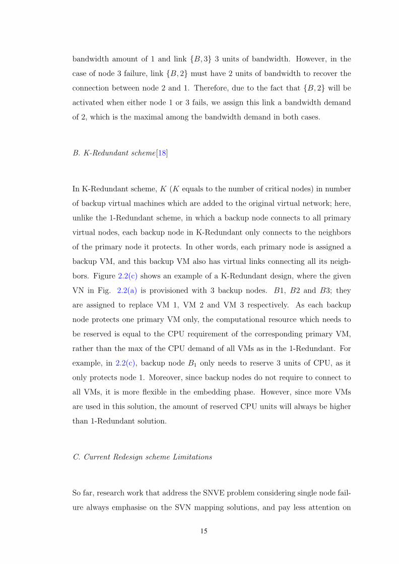
A. Backup Sharing [18]
To explore bandwidth sharing, we first identify a working-group, denotes asWG(v)
and a backup-group BG(v) for each VM v ∈ Nv. A working-group WG(v) con-
tains virtual links that are connecting VM v itself and its neighbors. For instance,
in Figure 2.3, l{v1,v2} and l{v2,v4} are the working-group of virtual node v2. A
backup-group BG(v) represents the set of virtual backup links that are going to
16

Figure 2.3: Resource Sharing techniques in SVN embedding phrase
be activiated after the failure of node v. They are usually connecting v’s backup
VM and v’s neighbors [18]. In Fig. 2.3, the backup-group of VM v4 has link
l{v2,B} and l{v3,B}. Upon the failure of v4, it migrates to VM B and continues
communicating with v2 and v3 via l{v2,B} and l{v3,B}.
Given the backup-group of each virtual node, it is obvious that links in different
backup-groups will not be activiated at the same time, as we only consider single
node failure. Hence, if the mapping of the virtual links in different backup-groups
have common substrate links, the bandwidth resource reserved on that specific
physical link can be shared, and only the maximal amount needs be allocated. In
Figure 2.3, l{v1,B} is in BG(v2) and BG(v3), whereas l{v1,B} can be in the backup-
group of v1 and v4. Therefore, those two virtual links will never be activated
simultaneously, thus upon the link mapping, l{v1,B} and l{v2,B} pass through two
common substrate links l{D,C} and l{C,B}, on which the reserved bandwidth can
be shared. Therefore, we allocate only 1 unit of backup bandwidth on substrate
links l{D,C} and l{C,B}, whereas without sharing 2 units must be reserved on them.
17
We denote such type of sharing ”backup share”[18].
B. Cross Sharing [18]
Upon the failure of a facility node, the VM(s) running on top of this node will fail
as well, and the communications between this VM and other VMs in the same vir-
tual network are disconnected. As a result, there will be some bandwidth released
from those disconnected communications which then can be reused by the backup
virtual links, only if the disconnected virtual primary links are in WG(v) and the
backup virtual links are in BG(v). For instance, in Figure 2.3, l{v3,v4} and l{v3,B}
are in WG(v4) and BG(v4) respectively, so the failure of v4 will disconnect l{v3,v4},
which is mapped on substrate link l{E,F}; the amount of bandwidth reserved on it
will be released, and since l{v3,B} will be activated after the failure, the released
1 unit of bandwidth on substrate link l{E,F} can be reused by l{v3,B}, therefore,
there is no need to provision backup on l{E,F}. We classify such bandwidth sharing
stragegy as ”cross share”[18].
C. Current Resource Sharing Methods Limitations
In existing SVNE solutions, resources sharing normally happens in the embedding
phase, and is encouraged throughout the whole process, in both node mapping
and link mapping. To achieve optimal solution for the embedding problem, one
must add both cross share and backup share as constraints to reduce the mapping
cost. The mapping of both primary and backup resources would be decided with
the objective of maximizing shared resources. This attempt puts the SVN embed-
ding into an awkward position, as the SVN intends to be embedded in a way that
the shared resources are maximized; on the other hand, the resources can only be
shared once the mapping solution are given. This fact slows down the execution
of the SVNE solutions. Therefore, the challenge is to find a time-efficient search
technique that utilizes resources sharing as much as possible. Hence, a prognostic
18

SVN redesign technique ”ProRed” is proposed in this thesis, the highlight of this
technique is its ability to consider the resource sharing while augmenting backup
resources to the original VN, as if the redundant resources in the output SVN can
”predict” sharing at the virtual level. Consquently, upon the embedding phase,
the sharing does not need to be involved, and solutions can be found rapidly.
2.3 Multicast Virtual Network
One-to-many communication is quite common in multiple applications and ser-
vices hosted in cloud data center networks [35–41]. For instance, High Perfor-
mance Computing1 (HPC) applications often need to distribute a large amount of
data from storage to all compute nodes [39]. Web-search services are another ex-
ample of multicast services that consist of redirecting incoming search-queries to a
set of indexing servers [44]. Further, bandwidth-hungry Distributed File-Systems
(DFS) are common data center applications [37], [45], [46]. DFS divides files into
fixed-size chunks to be replicated and stored in different servers for reliability [35],
[37]. Moreover, multicasting can be employed for the distribution of executable
binaries among participating servers in map reduce-like cooperative computation
systems [35], [36].
Services with a one-to-many communication mode can be easily treated as unicast
by replicating the transmission to each receiver, or as broadcast by flooding the
data throughout the network [47]. However, if the multicast of data is occurring in
high volumes (e.g. HPC applications), then replacing these multiple unicast mes-
sages by a single multicast message can incur great benefits in terms of reducing
the computation efforts at the source node, greatly shrinking bandwidth consump-
tion in the network, and subsequently increasing the application’s throughput and
enhancing its response time. Similarly avoiding the use of broadcasting can al-
leviate unnecessary processing to detect and reject irrelevant traffic from nodes
1HPC applications are conventionally employed in distributed parallel computers such assupercomputers and grid-computing. However, the emergence of cloud computing has triggeredsignificant attention around the possibilities of migrating HPCs to the cloud [42, 43].
19

outside the multicast group. Hence, for network operators that host multicast
services with heavy traffic, it is imperative to have efficient multicast support in
their data center networks.
IP Multicast [48] is the traditional implementation of multicast in the Internet.
However, this former suffers from many limitations which have inhibited its ubiq-
uitous use. These limitations are mainly concerns of security, scalability, and flow
control [49]; many of which have been alleviated and tackled in data center net-
works owing to the emergence of Software Defined Networks (SDNs) [49]. SDN
provides a vantage point to network and applications information, allowing the
detection and handle of diverse service classes with distinct QoS requirements
(i.e. delay-sensitive multicast services). Further, it enables the support of multi-
cast in commodity-switches that lack built-in support. This emerging networking
paradigm has surpassed the mere potential to enable multicast in data center net-
works, rendering a fertile ground to innovate and enhance its adoption.
To this extent, multicast in data center networks has become a prominent research
topic [35, 37, 40, 41, 49–51], with particular attention to the resource allocation
problem of MVNs [40, 41, 50, 51]. The former consists of allocating physical re-
sources to the Virtual Machines (VMs) running a tenant’s service, and routing
the traffic flow between them via substrate paths. In the case of a multicast ser-
vice, this embedding problem differs from the classical (unicast) VNE problem
in many aspects; mainly, a multicast VN comprises two types of virtual nodes
(machines): the multicast source node and a set of multicast recipient nodes (ter-
minals). The traffic flow routing now consists of building a multicast distribution
tree between the multicast source and terminals in order to avoid redundant traffic.
Also, multicast services that involve real-time communication entail stringent QoS
requirements, such as end-delay and delay-variation constraints. Another QoS re-
quirement that both unicast and multicast VNs share is a demand for reliability
guarantees; that is a reassurance that the hosted service will remain up and run-
ning despite any network component failure. Failure in the physical infrastructure
is common due to a multitude of reasons [52] that can affect one or many network
component. In fact, it can either attain a facility node (servers), a network node
20
(e.g. router/switch), or a substrate link.
Although the problem of survivable unicast VNs has been widely discussed [33],
the impact of failure on multicast services differs in several aspects, which ulti-
mately inhibit the applicability of existing unicast protection schemes. Indeed,
in this case, restoring a failed service component is not solely restricted to find-
ing a backup that matches the failed component’s resource demands, but also to
connect this backup to the rest of the multicast service while satisfying its QoS
requirements, and maintaining a low cost distribution tree. Therefore, this work
is dedicated towards studying the problem of reliable MVNs in failure-prone data
center networks, and propose a novel post-failure restoration scheme with tree
maintenance. Our work is different from the relevant literature [40], since our
proposed protection scheme capable of restoring MVNs against any single facility
node or substrate link failure. Further, our tree maintenance component guaran-
tees that the restored solution maintains a low cost tree that respects the delay
constraints of the restored MVN services. Our numerical results prove that our
suggested approach outperforms existing protection schemes in terms of achievable
long-term revenue.
In Chapter 4, an effort has been put on embedded multicast virtual networks
considering the case of single node failure.
21
Chapter 3
Survivable Virtual Network
Redesign and Embedding
3.1 Introduction
Network virtualization is a key enabler of the multi-tenancy concept [25], where
multiple network architectures and services can run on top of the same physical
infrastructure. With network virtualization, the problem of allocating resources
to the various tenants emerges as a challenging problem. This problem is formally
known as the Virtual Network Embedding problem (VNE), which is proven to be
NP-Hard [4]; therefore, numerous efforts have been devoted towards inaugurat-
ing effective heuristics for solving it [19, 20, 53–55]. The main weakness in these
suggested approaches, in addition to the lack of a guarantee on the quality of the
obtained solution, is that they assume that the physical infrastructure is available
at all times, which renders most of the work in the area of VNE inapplicable in
scenarios where network component failures can occur. Failures in the physical
infrastructure are common due to a multitude of reasons [56]. In fact, the year
2013 has witnessed multiple cloud outages[57]; one of which got hold of the famous
Amazon’s EC2 cloud, causing 5 million dollars in revenue loss for a single hour of
22
offline time. With millions of dollars at stake, attention converged towards solv-
ing the Survivable Virtual Network Embedding problem (SVNE) [6, 7, 14–18, 31].
Given that the SVNE problem is a variation of the VNE problem, it is also NP-
Hard. Hence, most of the relevant literature relax the problem by targeting one
network component failure type: facility node failures, network node failures, or
link failures, as illustrated in Figure 2.1. Some further simplify the problem by
considering that a single network component can fail at any given point in time.
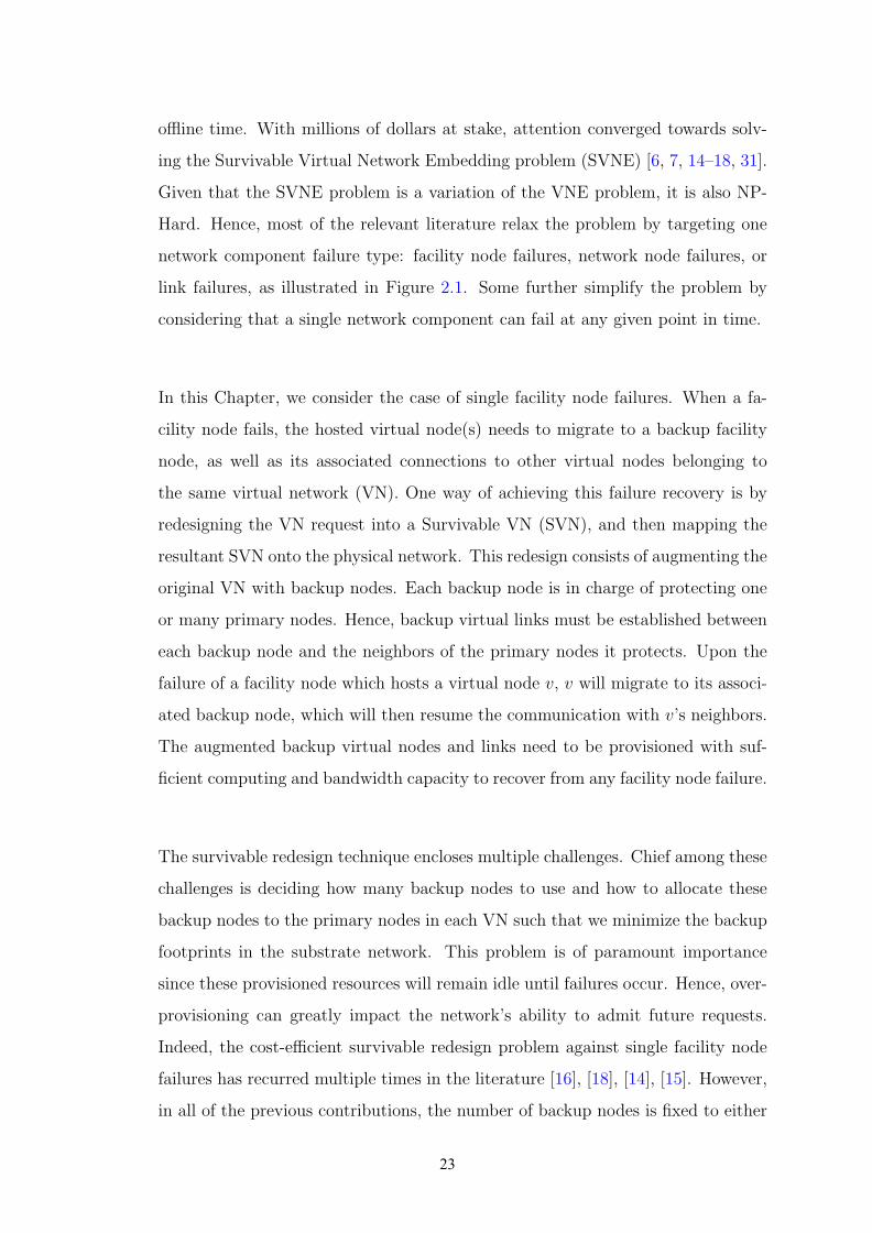
In this Chapter, we consider the case of single facility node failures. When a fa-
cility node fails, the hosted virtual node(s) needs to migrate to a backup facility
node, as well as its associated connections to other virtual nodes belonging to
the same virtual network (VN). One way of achieving this failure recovery is by
redesigning the VN request into a Survivable VN (SVN), and then mapping the
resultant SVN onto the physical network. This redesign consists of augmenting the
original VN with backup nodes. Each backup node is in charge of protecting one
or many primary nodes. Hence, backup virtual links must be established between
each backup node and the neighbors of the primary nodes it protects. Upon the
failure of a facility node which hosts a virtual node v, v will migrate to its associ-
ated backup node, which will then resume the communication with v’s neighbors.
The augmented backup virtual nodes and links need to be provisioned with suf-
ficient computing and bandwidth capacity to recover from any facility node failure.
The survivable redesign technique encloses multiple challenges. Chief among these
challenges is deciding how many backup nodes to use and how to allocate these
backup nodes to the primary nodes in each VN such that we minimize the backup
footprints in the substrate network. This problem is of paramount importance
since these provisioned resources will remain idle until failures occur. Hence, over-
provisioning can greatly impact the network’s ability to admit future requests.
Indeed, the cost-efficient survivable redesign problem against single facility node
failures has recurred multiple times in the literature [16], [18], [14], [15]. However,
in all of the previous contributions, the number of backup nodes is fixed to either
23

1 or k, k being the number of critical nodes in a given VN. In addition, to cir-
cumvent the inconvenience of idle resources, these latter introduce various backup
resource sharing opportunities which can be exploited in the substrate network
upon mapping the resultant SVN. In this Chapter, we argue that fixing the num-
ber of backup nodes to either 1 or k could yield infeasible or even costly mapping
solutions. We provide several motivational examples to support our proclama-
tion. Moreover, we observe that all of the aforementioned redesign techniques are
agnostic to the backup resource sharing in the substrate network, where this re-
sponsibility is delegated to the adopted mapping algorithm. This is problematic,
since given that the SVNE is NP-Hard[4], adding more constraints for backup
resource sharing will surely yield a more complex model. Hence, the existing lit-
erature solve this problem by relaxing the SVNE algorithm [6, 7, 14–18, 31]. For
instance, by solving the virtual node mapping and virtual link mapping disjointly
[6], [16], [7], [17], [14], [15] or by performing the primary and backup mapping
in a sequential fashion [6], [31], [18], [14]. Multiple other decomposition schemes
can be applied; however, it is these very same relaxation techniques that sacrifice
the quality of the obtained solution. This results in costly embedding solutions
that are incapable of exploiting backup resource sharing in the substrate network,
and lead to a substantial amount of backup idle resources that limit the cloud
provider’s long term revenue.
In light of the above, we introduce Pro-Red; a novel prognostic redesign approach
that explores the space between 1 and k and promotes backup resource sharing at
the VN level. Hence, it alleviates this concern from the embedding algorithm and
achieves cost-efficient SVNs using abridged mapping techniques. Pro-Red adopts
a unique approach for the redesign; not only does it determine the augmented
number of backup nodes and their connections to the primary nodes, but also
their actual positioning in the VN such that it minimizes the provisioned cost at
the substrate level. Hence, its prognostic property lays in its ability to foretell the
backup resource sharing at the VN level, prior to the embedding phase. Our nu-
merical results prove that our suggested approach yields significant gain in terms
of increasing the substrate network’s admission rate, decreasing the amount of idle
24

bandwidth in the substrate network, and boosting the overall revenue of the cloud
provider.
In this Chapter, we focus on the case of single facility node failure. Our work
is different since mainly we prove that while existing techniques tend to fix the
number of back-up nodes to either 1 or k, in this Chapter we present firm motiva-
tional examples that prove that in many cases the 1 or k redundant schemes can
yield infeasible or costly mapping solutions. Hence, we introduce a novel redesign
technique that is capable of exploring the space between 1 and k. Further, while
all of the existing work employs backup-sharing during the embedding phase, we
swerve from this conventional approach and take the backup-sharing to the VN
level by designing SVN with inherit back-sharing properties. This allows us to
embed the SVN as a VN without the complication of backup-sharing concerns
that surely yield a more complex mapping.
The rest of this Chapter is organized as follows: Section 2.2.1 is dedicated for
highlighting related work in the literature. In Section 3.2, we formally present the
SVN redesign problem for single facility node failure. Section 3.3 presents firm
motivational examples that prove the misfits of conventional redesign techniques.
In Section 3.4, we introduce the theocratical foundation of Pro-Red, and then
present its step-by-step procedural details. Section 3.5 introduces our SVN em-
bedding model that complements the features of Pro-Red. Section 3.6 is dedicated
for the numerical results. We conclude this Chapter in Section 3.7.
3.2 Problem Definition
1. The Substrate Network : We represent the substrate network as an undi-
rected graph denoted by Gs = (N ,L), where N is the set of substrate facility
nodes, and L is the set of substrate links. Facility nodes are connected to the
network via network nodes (routers/switches). Each substrate facility node n
25

V3
(a) Virtual Network
(6) (8)
10
10
1010
(10) (10)
(10) (10)S 3
S 1 S 2
S 4
(b) S ubstrateNetwork
V2 V3
B1
(c) S urvivableVirtual Network
(6) (8)
(8)V1
(4)
1 2
V1
(4)
1 22
1 2
V2
Figure 3.1: Substrate Network and Virtual Network Representation
∈ N is associated with a finite computing capacity, denoted by cn. Similarly,
each substrate link l ∈ L has a finite bandwidth capacity, denoted by dl. Fig-
ure 3.1 illustrates a substrate network with 4 facility nodes, each with a CPU
capacity of 10 units (represented by the number in parenthesis above each fa-
cility node). Similarly, we observe that the substrate links interconnecting the
network nodes exhibit 10 units of bandwidth capacity each (represented by the
number in parenthesis above each substrate link).
2. The Virtual Network (VN) : A Virtual network represents a client’s request
to deploy an application in a cloud data center. It consists of a set of virtual
nodes (virtual machines), interconnected with virtual links. The virtual links
correspond to the communication requirements between the virtual nodes in a
given VN request. We denote a VN as a virtual graph Gv = (V ,E), where V
represents the set of virtual nodes, each with a CPU demand of cv, and e is the
set of virtual links, each with a bandwidth demand of de. Figure 3.1 shows an
example of a VN request with 3 virtual nodes and links, in addition to their
associated CPU and bandwidth demands, respectively.
3. Problem Definition 1: Given the VN request, the SVNE problem aims
to map this request onto the substrate network while providing survivability
against single facility node failures. This can be done by redesigning the VN
request into an SVN, which consists of augmenting the VN with backup nodes
and provisioning enough bandwidth and CPU resources to recover from any
26

facility node failure. The problem of designing reliable VNs encloses two major
concerns: First, deciding how many backup nodes are needed to protect a given
VN, and second, determining which backup node will be in charge of protecting
which set of critical nodes. These two concerns highly depend on the substrate
network capacity. On one hand, provisioning a high number of backup nodes
and links greatly decreases the substrate network’s admission rate, since these
resources will remain idle until failure occurs. On the other hand, limiting
the number of backup nodes to a pre-determined constant may yield infeasible
mapping solutions. Hence, finding the optimal design of reliable VNs consists
of finding the tradeoff between the amount of backup resources provisioned and
the efficient utilization of the substrate network. The SVN redesign problem
can thus be formulated as follows:
Problem Definition 2. Given a substrate network Gs = (N,L), and a VN
request Gv = (V ,E), Find the optimal redesign d of the given VN request Gv
into a reliable VN (SVN), such that the amount of backup idle resources in the
substrate network is minimized, while guaranteeing survivability against single
facility node failure.
One way to solve the problem is by enumerating all possible designs d ∈ D, where
each d can contain between 1 to k backup nodes. For any given i (2 ≤ i ≤ k), there
could exist multiple designs d. These designs are represented by the different ways
the V virtual nodes are divided into i clusters, where each cluster is protected
by a single backup node. This is similar to the various ways n distinct objects
can be distributed into m different bins with k1 objects in the first bin, k2 in the
second, etc. and k1 + k2 + ....km = n. This indeed is obtained by applying the
multinomial theorem where∑
k1+k2+...+km=n
(n
k1+k2+...+km
)= mn. Therefore, for V
virtual nodes and i backup nodes, there are |V |i different mapping designs. Once
the set of all possible designs d is enumerated, it can be fed to an ILP model to
determine the optimal design d that achieves the lowest amount of backup idle
resources in the substrate network. It is important to note that in order for the
model to determine the optimal design, it requires to solve the SVNE for each
27
design d; this renders the problem NP-Hard.
In this regard, we reformulate the problem to seek a redesign approach that pro-
motes backup sharing in the substrate network, hence it is inheritably capable of
minimizing the backup footprints. In section 3.4, we introduce a heuristic-based
redesign approach that renders such prognostic SVNs.
3.3 The SVN Redesign Problem
3.3.1 Limitations of Conventional VN Redesign Techniques
One of the most commonly adopted redesign techniques for recovery against single
node failure are formally known as the 1-redundant and k-redundant schemes. In
the case of the 1-redundant scheme, the VN request is augmented with a single
backup node that needs to be connected to the neighbors of each critical node
via backup virtual links. Next, the resultant SVN is embedded onto the substrate
network while forcing the primary and backup nodes in a given SVN to occupy
distinct substrate nodes. This ensures that a single substrate node failure will
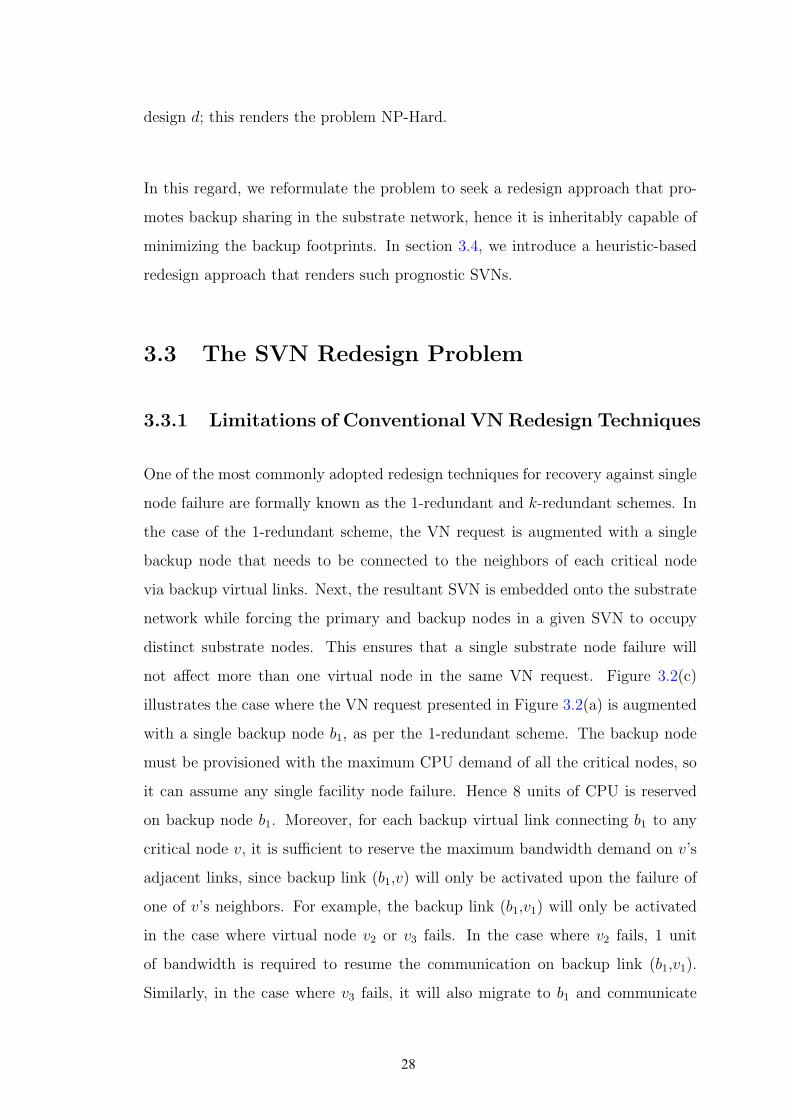
not affect more than one virtual node in the same VN request. Figure 3.2(c)
illustrates the case where the VN request presented in Figure 3.2(a) is augmented
with a single backup node b1, as per the 1-redundant scheme. The backup node
must be provisioned with the maximum CPU demand of all the critical nodes, so
it can assume any single facility node failure. Hence 8 units of CPU is reserved
on backup node b1. Moreover, for each backup virtual link connecting b1 to any
critical node v, it is sufficient to reserve the maximum bandwidth demand on v’s
adjacent links, since backup link (b1,v) will only be activated upon the failure of
one of v’s neighbors. For example, the backup link (b1,v1) will only be activated
in the case where virtual node v2 or v3 fails. In the case where v2 fails, 1 unit
of bandwidth is required to resume the communication on backup link (b1,v1).
Similarly, in the case where v3 fails, it will also migrate to b1 and communicate
28

10
10
1010
(10) (10)
(10) (10)S 3
S 1 S 2
S 4
V1 V2
B1
1
2
Cross-Share
Backup-Share
0
V3
2 Working
Paths
Backup
Paths
2
(a) Backup Resource Sharing
1
1 1
1
V1
V3
1
V4
1
1
1
V2
B1
(b) 1-Redundant SVN
V1
V3
1
V4
1
1
1
V2
1
1
11
B1B2
1
1
1
1
(c) 2-Redundant SVN
1 1
1
1
1
11
(5) (5) (5)
(5) (5) (5)
V2 B1
Released
Working
Paths
Primary
Working Paths
Backup
Paths
S 1 S 2 S 3
S 4 S 5S 6
V1
V4 V3
(d) 1-Redundant SVN Embedding Solution (1)
(5) (5) (5)
(5) (5) (5)
V1 V2B1
B2
1 1
1
1
1
11
Released
Working
Paths
Cross-ShareCross-
Share
S 1 S 2 S 3
S 4
V3V4
S 5 S 6
(e) 2-Redundant SVN Embedding
(5) (5) (5)
(5) (5) (5)
V2B1
1 1
11
21
V3
1
Released
Working
Paths
Cross-share Cross-share
2
Reserved
Bandwidth
S 1 S 2 S 3
S 4 S 5 S 6
V1
V4
(f) 1-Redundant SVN Embedding Solution (2)
Figure 3.2: Designing and Embedding Reliable VNs
with v1 with 2 units of bandwidth. Given that at any point in time either v2 or v3
would fail, it is sufficient to reserve 2 units of bandwidth on the link connecting b1
to v1. The set of backup links that are activated simultaneously upon the failure of
a virtual node v are denoted as the Backup-Group of v (BG(v)) [18]. For instance,
the BG(v1) contains backup links (b1,v2) and (b1,v3). Similarly, the backup group
29

of BG(v2) and BG(v2) is (b1,v1).
Now, for the k-redundant scheme, the VN is augmented with k backup nodes,
where k represents the number of primary critical nodes. In this case, each backup
virtual node protects a single primary node, and hence it only connects to its
neighbors via backup virtual links. Each backup node along with its associated
backup links will be provisioned with the same amount of resources as the primary
node it protects and its adjacent links, respectively.
When a facility node fails, only the affected node will be disconnected from the
substrate network. However, its adjacent network node and substrate links will
remain active and capable of routing traffic. Thus, upon the failure of a facility
node that hosts a virtual node v, the bandwidth on the original working paths
that connect v to its neighbors in the substrate network will be released, and
hence becomes available. This released bandwidth can thus be reused by the
corresponding backup paths of v’s backup node. Such type of sharing is known
as cross− sharing [18] between working and backup paths. Each virtual node v
is associated with a working-group (WG(v)) that contains the set of v’s working
paths. For instance, the WG(v1) contains (v1,v2) and (v1,v3). Hence, the BG(v1)
can reuse the bandwidth of the WG(v1) upon v1’s failure through cross-sharing.
Moreover, given that a single node might fail at any point in time, the backup paths
belonging to different backup groups can share their bandwidth in the substrate
network. Such type of sharing is referred to as backup − sharing [18]. Figure
3.2(a) shows a mapping solution for the 1-redundant SVN presented in Figure
3.2(c) over the substrate network in Figure 3.2(b). We observe that for backup
link (b1,v3), 4 units of bandwidth needs to be reserved, since the substrate links
that route this backup path do not overlap with any other appropriate backup or
working paths. However, backup paths (b1,v1) and (b2,v2) overlap over substrate
link {s2,s4}; and given that these backup paths belong to distinct backup groups,
only 2 units of bandwidth need to be reserved on substrate link {s2,s4}, rather
than 3 due to backup-sharing. Moreover, backup path (b1,v1) further overlaps with
working path (v1,v2) on substrate link {s1,s2}; hence 0 units of bandwidth needs
to be reserved on this substrate link via cross-sharing.
30
The problem with the 1-redundant and k-redundant schemes is that by forcing
the number of backup nodes to be either 1 of k, we may end-up with infeasible
or costly mapping solutions. This is due to the fact that the substrate might not
have enough bandwidth capacity to route the traffic between 1 backup node to the
neighbors of all critical nodes, in the case of the 1-redundant scheme. Whereas, in
the case of the k-redundant scheme, a substantial amount of CPU resources remain
idle until a failure occurs, since k-redundant requires as many backup nodes as
primary critical nodes, not to mention the large number of backup virtual links
needed to associate each backup node with its appropriate primary critical node.
This motivates the need for a cost-efficient redesign technique that is capable of
exploring the space between 1 and k, and finding the balance between the amount
of provisioned CPU and bandwidth to yield feasible and cost-efficient embedding
solutions.
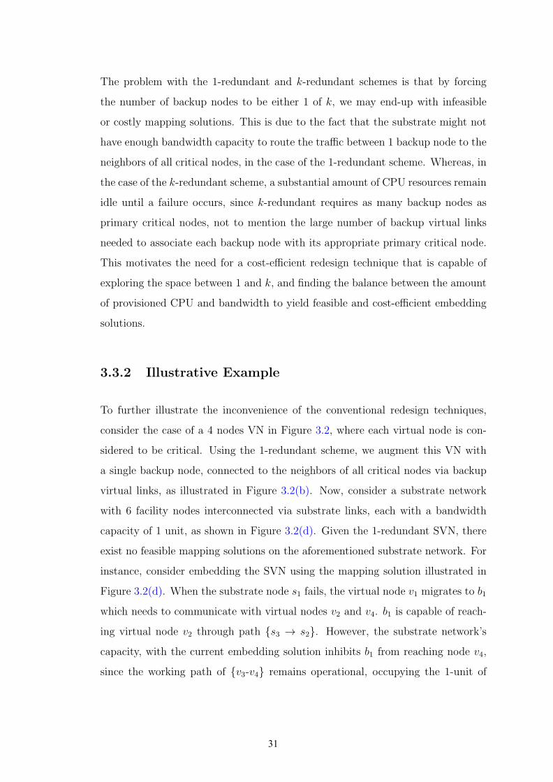
3.3.2 Illustrative Example
To further illustrate the inconvenience of the conventional redesign techniques,
consider the case of a 4 nodes VN in Figure 3.2, where each virtual node is con-
sidered to be critical. Using the 1-redundant scheme, we augment this VN with
a single backup node, connected to the neighbors of all critical nodes via backup
virtual links, as illustrated in Figure 3.2(b). Now, consider a substrate network
with 6 facility nodes interconnected via substrate links, each with a bandwidth
capacity of 1 unit, as shown in Figure 3.2(d). Given the 1-redundant SVN, there
exist no feasible mapping solutions on the aforementioned substrate network. For
instance, consider embedding the SVN using the mapping solution illustrated in
Figure 3.2(d). When the substrate node s1 fails, the virtual node v1 migrates to b1
which needs to communicate with virtual nodes v2 and v4. b1 is capable of reach-
ing virtual node v2 through path {s3 → s2}. However, the substrate network’s
capacity, with the current embedding solution inhibits b1 from reaching node v4,
since the working path of {v3-v4} remains operational, occupying the 1-unit of
31

bandwidth on the substrate link {s4-s5}. This renders the embedding solution il-
lustrated in Figure 3.2(d) infeasible. By examining all possible mapping solutions
of the 1-redundant SVN on the given substrate network, we find that they are all
infeasible. This is because the 1-redundant scheme connects a single backup node
to the neighbors of all critical nodes. Hence b1’s bandwidth demand along with
the given substrate network capacity, inhibits b1 from protecting this VN against
any single node failures.
On the other hand, consider the case where the aforementioned VN is augmented
with 2 backup nodes b1 and b2, as shown in Figure 3.2(c). b1 assumes the failure of
critical nodes v1 and v2, and b2 replaces v3 and v4 in case any of them failed. Upon
embedding the resultant SVN, we notice that this reliable design does indeed yield
a feasible solution and requires 0 units of reserved bandwidth due to cross-sharing,
as illustrated in Figure 3.2(e). For example, consider the case where the facility
node s1 fails; subsequently, v1 will migrate to b1, and that latter needs to resume
v1’s communication with v2 and v4. The failure of virtual node v1 leads to the
release of the active bandwidth on working paths {s1-s2} and {s1-s4} connecting
virtual node v1 to v2 and v4, respectively. The released bandwidth will be reused
by b1 to reach v2 and v4 through cross-sharing. By employing cross-sharing for
all other virtual node failures in the given VN, we can conclude that indeed the
2-redundant SVN requires 0 unit of reserved bandwidth.
Further, consider the same substrate network, where link {s2 → s5} has a capacity
of 2 units, as illustrated in Figure 3.2(f). In this case, we can indeed find a feasible
embedding solution for the 1-redundant SVN with a provisioned bandwidth cost
of 2 units, whereas the 2-redundant scheme still requires 0 units of provisioned
bandwidth.
These motivational examples prove our proclamation that by forcing the number
of backup nodes to be either 1 or k, we might end up with infeasible or costly
mapping solutions. Whereas when we augment the VN with i (1 ≤ i ≤ k) backup
nodes (i = 2 in the above example), we achieve a balance between the amount of
backup bandwidth and CPU that needs to be reserved. In fact, this balance yields
a feasible solution, when the 1-redundant and k-redundant fail to find one.
32

This motivates the need for a redesign approach that is capable of finding that
balance, rather than being fixed to either 1 or k backup nodes. By exploring the
space in the range between 1 and k, we can obtain lower-cost mapping solutions,
and increase the network’s admissibility. This is one of Pro-Red’s unique capa-
bilities. Another advantage of Pro-Red is that it redesigns the VN in a way to
promote the backup bandwidth sharing at the substrate network. In the next
section we present Pro-Red’s theoretical foundation that enables it to fulfil these
two promises.
3.4 Prognostic Redesign Approach (Pro-Red) :
3.4.1 Theoretical Foundation
V11
V2V1 V2
1 1V1 V2
1 1
1
B1
B2
(a) (b) (c)
Figure 3.3: Theoretical Foundation
In this section, we present the theoretical foundation on which Pro-Red’s redesign
technique is established. We begin our explanation with a motivational example:
Consider a 2 nodes VN illustrated in Figure 3.3(a). Augmenting the VN with a
single backup node, using the 1-redundant scheme, requires 2 units of reserved
bandwidth (as shown in Figure 3.3(b)). By employing an effective embedding
approach, this estimated bandwidth cost could be minimized at the substrate
network level via cross-sharing and backup-sharing. Observe, however, that by
placing this backup node along the path connecting v1 and v2, the resulting SVN
will require 0 additional units of bandwidth once embedded into the substrate
network. This is due to the fact that by placing the backup node in between
its associated primary nodes, we force the primary path that routes the traffic
33
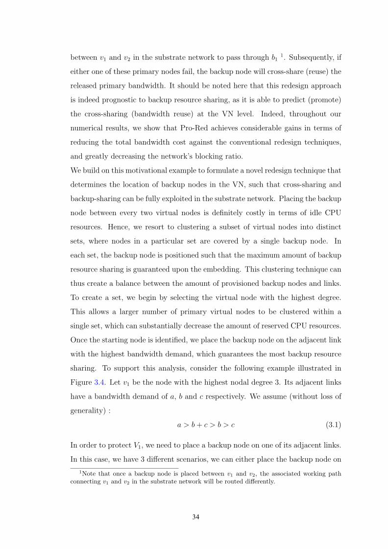
between v1 and v2 in the substrate network to pass through b11. Subsequently, if
either one of these primary nodes fail, the backup node will cross-share (reuse) the
released primary bandwidth. It should be noted here that this redesign approach
is indeed prognostic to backup resource sharing, as it is able to predict (promote)
the cross-sharing (bandwidth reuse) at the VN level. Indeed, throughout our
numerical results, we show that Pro-Red achieves considerable gains in terms of
reducing the total bandwidth cost against the conventional redesign techniques,
and greatly decreasing the network’s blocking ratio.
We build on this motivational example to formulate a novel redesign technique that
determines the location of backup nodes in the VN, such that cross-sharing and
backup-sharing can be fully exploited in the substrate network. Placing the backup
node between every two virtual nodes is definitely costly in terms of idle CPU
resources. Hence, we resort to clustering a subset of virtual nodes into distinct
sets, where nodes in a particular set are covered by a single backup node. In
each set, the backup node is positioned such that the maximum amount of backup
resource sharing is guaranteed upon the embedding. This clustering technique can
thus create a balance between the amount of provisioned backup nodes and links.
To create a set, we begin by selecting the virtual node with the highest degree.
This allows a larger number of primary virtual nodes to be clustered within a
single set, which can substantially decrease the amount of reserved CPU resources.
Once the starting node is identified, we place the backup node on the adjacent link
with the highest bandwidth demand, which guarantees the most backup resource
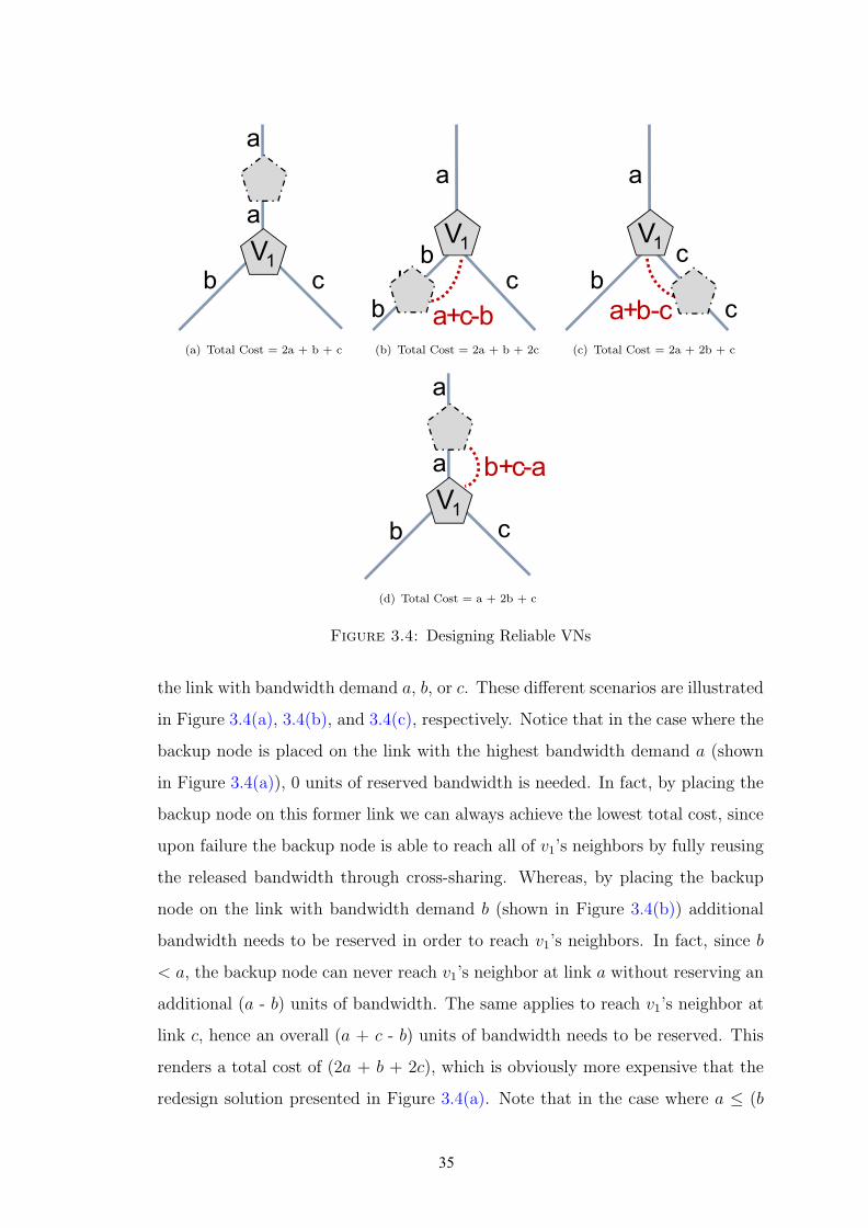
sharing. To support this analysis, consider the following example illustrated in
Figure 3.4. Let v1 be the node with the highest nodal degree 3. Its adjacent links
have a bandwidth demand of a, b and c respectively. We assume (without loss of
generality) :
a > b+ c > b > c (3.1)
In order to protect V1, we need to place a backup node on one of its adjacent links.
In this case, we have 3 different scenarios, we can either place the backup node on
1Note that once a backup node is placed between v1 and v2, the associated working pathconnecting v1 and v2 in the substrate network will be routed differently.
34
V1
a
a
b c
(a) Total Cost = 2a + b + c
V1
a
b c
b
b a+c-b
(b) Total Cost = 2a + b + 2c
V1
a
b
c
ca+b-c
(c) Total Cost = 2a + 2b + c
V1
a
a
b c
b+c-a
(d) Total Cost = a + 2b + c
Figure 3.4: Designing Reliable VNs
the link with bandwidth demand a, b, or c. These different scenarios are illustrated
in Figure 3.4(a), 3.4(b), and 3.4(c), respectively. Notice that in the case where the
backup node is placed on the link with the highest bandwidth demand a (shown
in Figure 3.4(a)), 0 units of reserved bandwidth is needed. In fact, by placing the
backup node on this former link we can always achieve the lowest total cost, since
upon failure the backup node is able to reach all of v1’s neighbors by fully reusing
the released bandwidth through cross-sharing. Whereas, by placing the backup
node on the link with bandwidth demand b (shown in Figure 3.4(b)) additional
bandwidth needs to be reserved in order to reach v1’s neighbors. In fact, since b
< a, the backup node can never reach v1’s neighbor at link a without reserving an
additional (a - b) units of bandwidth. The same applies to reach v1’s neighbor at
link c, hence an overall (a + c - b) units of bandwidth needs to be reserved. This
renders a total cost of (2a + b + 2c), which is obviously more expensive that the
redesign solution presented in Figure 3.4(a). Note that in the case where a ≤ (b
35

+ c), and a is the link with the highest bandwidth demand; to place the backup
node on link a, a total of (b + c - a) must be reserved, as illustrated in Figure
3.4(d). However, this solution still renders the lowest total bandwidth cost.
3.4.2 Pro-Red Algorithm :
Algorithm 1 Pro-Red: Prognostic Redesign Heuristic
1: Given V (U,E) /*Virtual Network Topology*/2: /*Set cover flag for nodes and links to false*/3: for (u ∈ U) do4: u.covered = false;5: end for6: C = { }; /*Initialize the list of covered nodes*/7: while (—C— ¡ U) do8: C = {U} - C;9: Step 1: Find Starting Node10: v1 = GetNodeWithHighestNodeDegree(C);11: L = GetAllAdjacentLinks(v1, C);12: Step 2: Find Starting Link13: e = GetHighestBW (L);14: v2 = GetTheOtherNode(v1, e);15: Step 3: Create a new Set16: s = CreateSet(v1, v2, e);17: C = C ∪ {s};18: end while
In this section, we present the SVN redesign heuristic that is founded on the the-
ories and observations presented in Section 3.4.1. The objective of this algorithm
is to assign a backup node for each critical node in the given VN topology; we
refer to a critical node that is assigned to a backup node as covered (or protected).
Initially, all the virtual nodes in the VN topology are considered as uncovered;
hence, we initialize the virtual nodes with a cover flag set to false. Next, we define
two new sets C and C that are updated at the end of every iteration with the
list of covered and uncovered nodes, respectively. The process terminates when C
contains all the critical nodes in the VN request. At each iteration, the algorithm
creates a single set. We define a set as an ensemble of critical nodes protected by a
single backup node. To create a set, we first need to identify a starting point, from
which a set will begin and grow. Based on the previous observations presented
36
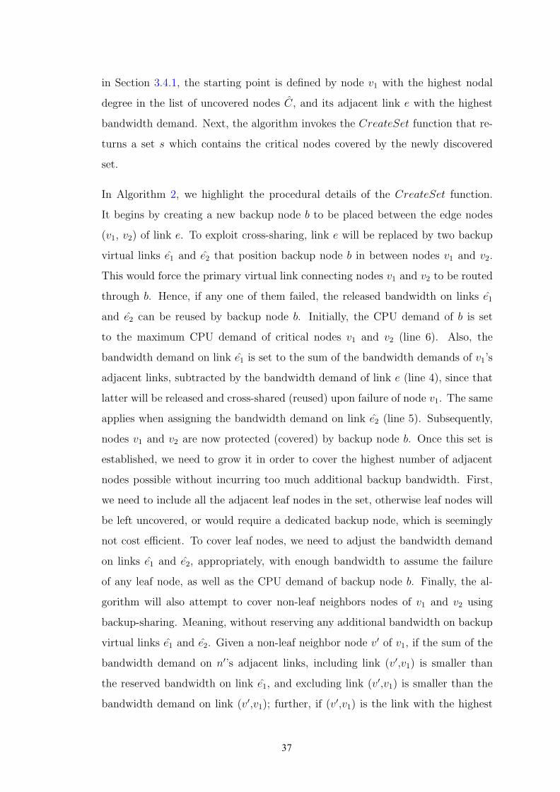
in Section 3.4.1, the starting point is defined by node v1 with the highest nodal
degree in the list of uncovered nodes C, and its adjacent link e with the highest
bandwidth demand. Next, the algorithm invokes the CreateSet function that re-
turns a set s which contains the critical nodes covered by the newly discovered
set.
In Algorithm 2, we highlight the procedural details of the CreateSet function.
It begins by creating a new backup node b to be placed between the edge nodes
(v1, v2) of link e. To exploit cross-sharing, link e will be replaced by two backup
virtual links e1 and e2 that position backup node b in between nodes v1 and v2.
This would force the primary virtual link connecting nodes v1 and v2 to be routed
through b. Hence, if any one of them failed, the released bandwidth on links e1
and e2 can be reused by backup node b. Initially, the CPU demand of b is set
to the maximum CPU demand of critical nodes v1 and v2 (line 6). Also, the
bandwidth demand on link e1 is set to the sum of the bandwidth demands of v1’s
adjacent links, subtracted by the bandwidth demand of link e (line 4), since that
latter will be released and cross-shared (reused) upon failure of node v1. The same
applies when assigning the bandwidth demand on link e2 (line 5). Subsequently,
nodes v1 and v2 are now protected (covered) by backup node b. Once this set is
established, we need to grow it in order to cover the highest number of adjacent
nodes possible without incurring too much additional backup bandwidth. First,
we need to include all the adjacent leaf nodes in the set, otherwise leaf nodes will
be left uncovered, or would require a dedicated backup node, which is seemingly
not cost efficient. To cover leaf nodes, we need to adjust the bandwidth demand
on links e1 and e2, appropriately, with enough bandwidth to assume the failure
of any leaf node, as well as the CPU demand of backup node b. Finally, the al-
gorithm will also attempt to cover non-leaf neighbors nodes of v1 and v2 using
backup-sharing. Meaning, without reserving any additional bandwidth on backup
virtual links e1 and e2. Given a non-leaf neighbor node v′ of v1, if the sum of the
bandwidth demand on n′’s adjacent links, including link (v′,v1) is smaller than
the reserved bandwidth on link e1, and excluding link (v′,v1) is smaller than the
bandwidth demand on link (v′,v1); further, if (v′,v1) is the link with the highest
37

Algorithm 2 CreateSet(virtual node v1, virtual node v2 virtual link e)
1: s = {};2: Step 4: Create a new backup node b
3: e1 = new virtual link(v1,b);4: e2 = new virtual link(v2,b);5: setCPU(b,max(v1,v2));6: de1 = de2 = de;7: if (Sum(GetAdjacentLinksBandwidth(v1)) ≥ 2de) then8: de1 = Sum(GetAdjacentLinksBandwidth(v1)) - de;9: end if
10: if (Sum(GetAdjacentLinksBandwidth(v2)) ≥ 2de) then11: de2 = Sum(GetAdjacentLinksBandwidth(v2)) - de;12: end if13: v1.covered = v2.covered = true;14: l.covered = true;15: s = s ∪ {v1,v2};16: Step 5: Protect Adjacent Leaf Nodes17: T = v1.getAdjacentLeafNodes()18: while (!T.isEmpty) do19: t = T .next();20: t.covered = true;21: s = s ∪ {t};22: setBW (e1,max(de1 ,d(v1,t)));23: setCPU(b,max(b,t));24: end while25: Repeat the same while loop for Adjacent leaf nodes of v226: Step 6: Protect Adjacent non-leaf Nodes27: R.addAll(getAdjacentNonLeafNode(v1));28: R.addAll(getAdjacentNonLeafNode(v2));29: while (v1.hasAdjacentNonLeafNodes()) do30: r = R.next();31: if ((2d(v1,r) ≥ Sum(GetAdjacentLinksBW (r)))&&32: (de1 ≥ d(v1,r) && (r.hasAdjacentLeafNodes() = null)) then33: r.covered = true;34: s = s ∪ r;35: setCPU(b,max(b,t));36: end if37: end while38: Repeat at line 21 for v239: return s;
38

bandwidth demand among v′’s adjacent links, then v′ could be included in v1’s set
and subsequently protected by backup node b without incurring any additional
backup bandwidth via backup-sharing. Finally, the algorithm returns the set of
nodes that are covered by the newly created set s. The CreateSet function has a
complexity of O(n), which renders the complexity of Pro-Red’s redesign heuristic
to be O(n2), since we call the CreateSet function for each uncovered node in the
VN request.
To further illustrate the enactment of Pro-Red’s redesign algorithm, consider the
VN topology presented in Figure 3.5(a). The algorithm begins by identifying a
starting node and link, which in this case are node v7 with link {v4,v7}, since they
correspond to the node with the highest degree, and its adjacent link with the
highest bandwidth demand. Next, a set is created by placing a backup node b1 on
link {v4,v7}, as shown in Figure 3.5(b). This implies that nodes v4 and v7 are now
protected by backup node b1. Since the sum of the adjacent links to v4 (excluding
link {v4,b1}) is smaller than the bandwidth on link {v4,b1}, 0 units of bandwidth
is required to protect node v4. When v4 fails, the bandwidth on the substrate
paths that are routing virtual links {v4,b1), (b1,v7}), {v4,v3}) and {v4,v5}) will be
released. Now, v4 will migrate to b1 and that latter needs to resume v4’s commu-
nication with v3, v5 and v7; b1 will thus reuse 8 units of released bandwidth on the
path connecting b1 to v7 to reach v7. Similarly, b1 will reuse 2 units of released
bandwidth on {v4,b1) and {v4,v3}) to reach v3, and 3 units on {v4,b1) and {v4,v7})
to reach v7.
Now to protect virtual nodes v7, we observe that the sum of its adjacent links is
12, which implies that 3 additional units of bandwidth must be reserved on link
{v7,b1} in order to protect node v7. This is because when v7 fails it migrates to b1,
that latter now needs to go through the path connecting b1 to v7 and then cross-
share the released bandwidth on the paths connecting v7 to v6, v8 and v9. Now,
given that only 8 units of bandwidth is released on {v7,b1}; hence, 3 additional
units must be reserved to fully protect v7.
Next, the set is grown by adding the adjacent leaf nodes of v4 and v7. The only
39
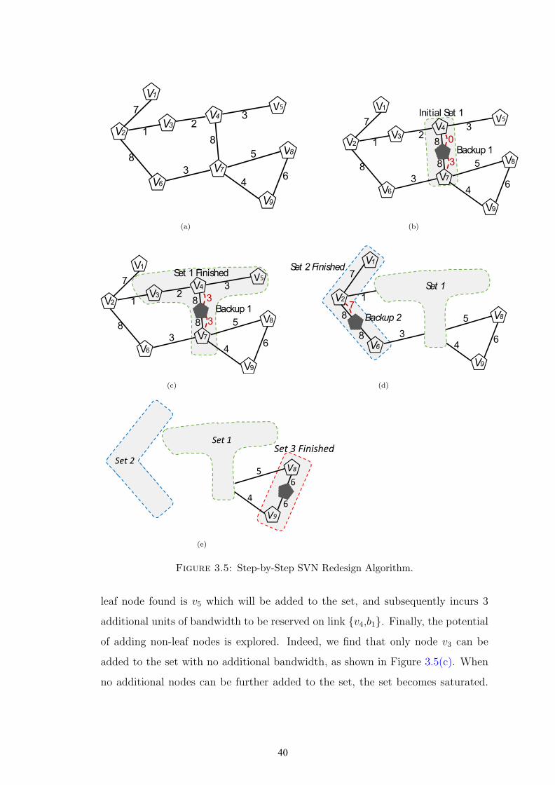
7
12
V1
V2V3
8
3
V6
3
8
V4
V
8
5
46
V7
V8
V9
(a)
Initial Set 1
Backup 10
3
7
8
12
3
8
3
5
46
V1
V2
V4
V6
V7
V8
V9
V3
8
(b)
3
Set 1 Finished
Backup 1
3
7
8
12
3
8
3
5
46
V1
V2
V4
V6
V7
V8
V9
V3
8
(c)
Set 2 Finished
3
7
12
3
8
V1
V2
V4V3
Set1Set 1
7
38
3
5
46
V6
V7
V8
V9
8Backup 2
8
7
(d)
3
7
8
2
3
8
5
V1
V2
V4
V8
V3
8
Set1
Set 1
Set 2
Set 3 Finished
8 5
4
6V7
V8
V9
8
8
6
(e)
Figure 3.5: Step-by-Step SVN Redesign Algorithm.
leaf node found is v5 which will be added to the set, and subsequently incurs 3
additional units of bandwidth to be reserved on link {v4,b1}. Finally, the potential
of adding non-leaf nodes is explored. Indeed, we find that only node v3 can be
added to the set with no additional bandwidth, as shown in Figure 3.5(c). When
no additional nodes can be further added to the set, the set becomes saturated.
40

Subsequently, the CreateSet function returns set s1 with backup node b1 protect-
ing virtual nodes v3, v4, v5, and v7, which leaves 5 critical nodes in the given VN
uncovered. Hence, a new set is initiated starting with node v2, since it represents
the next uncovered node with the highest nodal degree. The same process repeats,
and returns set s2 with backup node b2 protecting virtual nodes v1, v2, and v6, as
shown in Figure 3.5(d). Finally, set s3 is created with backup node b3 covering
nodes v8 and v9, illustrated in Figure 3.5(e). Once all critical nodes are protected,
the algorithm terminates. At the end, we obtain 3 sets with 3 backup nodes pro-
tecting 9 critical nodes with only 12 units of reserved bandwidth.
It is important to note that if we were to employ the 1-redundant scheme, then
a single backup node b needs to connect to each virtual node; hence a total of
9 backup links are needed. This means that potentially 47 units (sum of all
bandwidth demand in the given VN) of bandwidth needs to be reserved to connect
b to the virtual nodes. Here, the actual amount of reserved backup bandwidth in
the substrate network depends on the quality of the adopted SVNE approach. It
can indeed be substantially reduced with a highly-efficient embedding approach
that exploits cross-sharing and back-sharing; or it can get aggravated if the backup
node was poorly placed far from the primary virtual nodes, requiring multiple hops
to reach them. Versus in the case of ProRed, placing the backup nodes along the
paths connecting the primary nodes guarantees the predicted cross-sharing that
the resultant SVN will enjoy once embedded onto the substrate network.
3.5 The SVN Embedding
Upon obtaining the redesigned VN, the next step is to embed this latter onto
the substrate network. Since the SVNE problem is NP-Hard, we adopt a disjoint
mapping approach, where we preform the node mapping first and then the link
mapping. For the node mapping, we use the VMP algorithm in [16] to find a
set of M feasible node mapping solutions. Note both the primary and backup
41
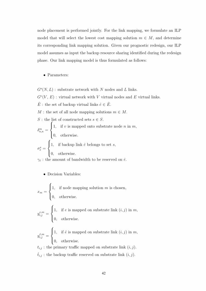
node placement is performed jointly. For the link mapping, we formulate an ILP
model that will select the lowest cost mapping solution m ∈ M , and determine
its corresponding link mapping solution. Given our prognostic redesign, our ILP
model assumes as input the backup resource sharing identified during the redesign
phase. Our link mapping model is thus formulated as follows:
• Parameters:
Gs(N,L) : substrate network with N nodes and L links.
Gv(V , E) : virtual network with V virtual nodes and E virtual links.
E : the set of backup virtual links e ∈ E.
M : the set of all node mapping solutions m ∈ M .
S : the list of constructed sets s ∈ S.
δmn,n =
1, if v is mapped onto substrate node n in m,
0, otherwise.
σse =
1, if backup link e belongs to set s,
0, otherwise.
γe : the amount of bandwidth to be reserved on e.
• Decision Variables:
xm =
1, if node mapping solution m is chosen,
0, otherwise.
ye,mi,j =
1, if e is mapped on substrate link (i, j) in m,
0, otherwise.
ye,mi,j =
1, if e is mapped on substrate link (i, j) in m,
0, otherwise.
ti,j : the primary traffic mapped on substrate link (i, j).
ti,j : the backup traffic reserved on substrate link (i, j).
42
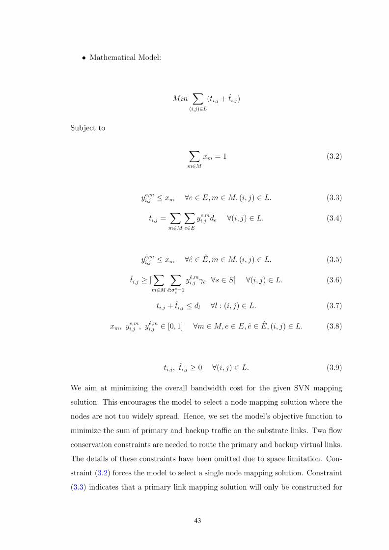
• Mathematical Model:
Min∑
(i,j)∈L
(ti,j + ti,j)
Subject to
∑
m∈M
xm = 1 (3.2)
ye,mi,j ≤ xm ∀e ∈ E,m ∈ M, (i, j) ∈ L. (3.3)
ti,j =∑
m∈M
∑
e∈E
ye,mi,j de ∀(i, j) ∈ L. (3.4)
ye,mi,j ≤ xm ∀e ∈ E,m ∈ M, (i, j) ∈ L. (3.5)
ti,j ≥ [∑
m∈M
∑
e:σse=1
ye,mi,j γe ∀s ∈ S] ∀(i, j) ∈ L. (3.6)
ti,j + ti,j ≤ dl ∀l : (i, j) ∈ L. (3.7)
xm, ye,mi,j , y
e,mi,j ∈ [0, 1] ∀m ∈ M, e ∈ E, e ∈ E, (i, j) ∈ L. (3.8)
ti,j, ti,j ≥ 0 ∀(i, j) ∈ L. (3.9)
We aim at minimizing the overall bandwidth cost for the given SVN mapping
solution. This encourages the model to select a node mapping solution where the
nodes are not too widely spread. Hence, we set the model’s objective function to
minimize the sum of primary and backup traffic on the substrate links. Two flow
conservation constraints are needed to route the primary and backup virtual links.
The details of these constraints have been omitted due to space limitation. Con-
straint (3.2) forces the model to select a single node mapping solution. Constraint
(3.3) indicates that a primary link mapping solution will only be constructed for
43

the chosen node mapping solution. Constraint (3.4) measures the primary traffic
routed on every physical link in the substrate network. Constraint (3.5) indicates
that a backup link mapping solution will only be constructed for the chosen node
mapping solution. Constraint (3.6) measures the backup link traffic routed on
every physical link in the substrate network. Notice that for every given link, the
amount of backup bandwidth reserved is the max of the sum of backup bandwidth
provisioned within each given set. This is because our approach enables backup
sharing among the backup virtual links belonging to distinct sets, since these latter
will not be activated at the same time. Constraint (3.7) ensures that the sum of
the primary and backup bandwidth routed on each substrate link does not violate
its capacity.
3.6 Numerical Results
We evaluate the performance of Pro-Red against the 1-redundant and k-redundant
schemes for various metrics: Blocking Ratio, Average Cost, Revenue and Execu-
tion Time. We adopt two different substrate network topologies to conduct this
evaluation. The substrate networks used for our simulation are FatTree (K=4)
[25], in addition to a randomly generated network [58] R, with 36 nodes and 48
links. In both these substrate networks, we set the CPU capacity of each host
node to 48 units, and the bandwidth capacity on the substrate links is set to 750
units. We perform the redesign and mapping of VNs in an online fashion, upon
the arrival of each request. Hence, we assume that the VNs arrival and departure
follow a Poisson distribution. The VN requests are randomly generated, where
the size of each VN can range between 2 to 8 virtual nodes. Each virtual node
can be connected to any other virtual node in the VN request with a probability
of 50%. The CPU demand of the virtual nodes is set to be in the range [1:5], and
the bandwidth demand on the virtual links is in the range [10:50]. To conduct the
comparison with 1-redundant and k-redundant, we employ the same embedding
44
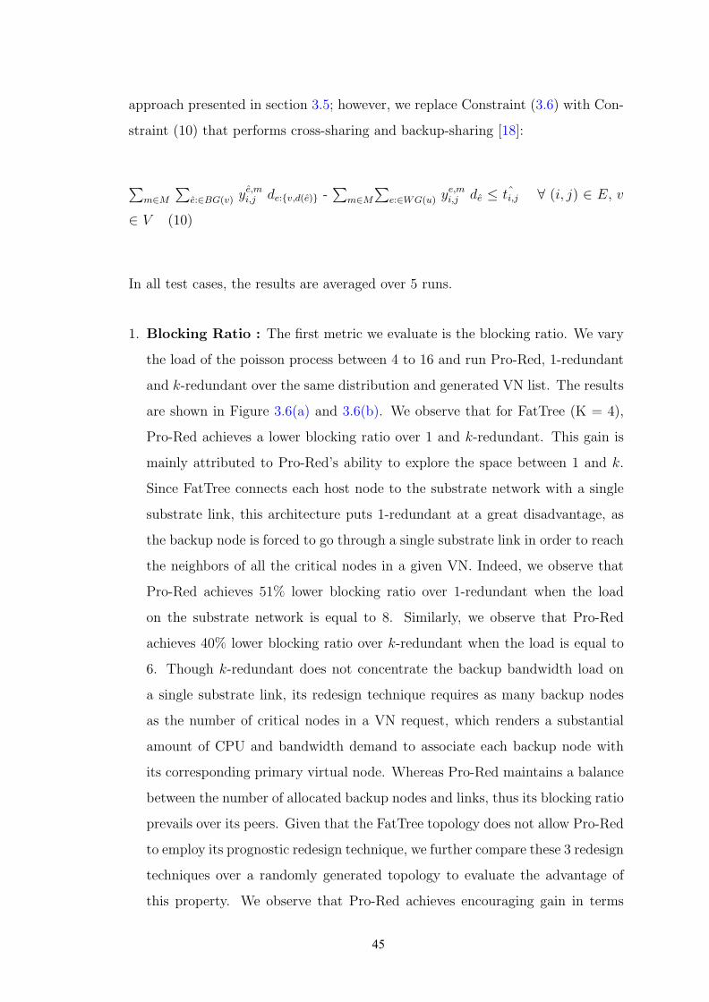
approach presented in section 3.5; however, we replace Constraint (3.6) with Con-
straint (10) that performs cross-sharing and backup-sharing [18]:
∑m∈M
∑e:∈BG(v) y
e,mi,j de:{v,d(e)} -
∑m∈M
∑e:∈WG(u) y
e,mi,j de ≤ ˆti,j ∀ (i, j) ∈ E, v
∈ V (10)
In all test cases, the results are averaged over 5 runs.
1. Blocking Ratio : The first metric we evaluate is the blocking ratio. We vary
the load of the poisson process between 4 to 16 and run Pro-Red, 1-redundant
and k-redundant over the same distribution and generated VN list. The results
are shown in Figure 3.6(a) and 3.6(b). We observe that for FatTree (K = 4),
Pro-Red achieves a lower blocking ratio over 1 and k-redundant. This gain is
mainly attributed to Pro-Red’s ability to explore the space between 1 and k.
Since FatTree connects each host node to the substrate network with a single
substrate link, this architecture puts 1-redundant at a great disadvantage, as
the backup node is forced to go through a single substrate link in order to reach
the neighbors of all the critical nodes in a given VN. Indeed, we observe that
Pro-Red achieves 51% lower blocking ratio over 1-redundant when the load
on the substrate network is equal to 8. Similarly, we observe that Pro-Red
achieves 40% lower blocking ratio over k-redundant when the load is equal to
6. Though k-redundant does not concentrate the backup bandwidth load on
a single substrate link, its redesign technique requires as many backup nodes
as the number of critical nodes in a VN request, which renders a substantial
amount of CPU and bandwidth demand to associate each backup node with
its corresponding primary virtual node. Whereas Pro-Red maintains a balance
between the number of allocated backup nodes and links, thus its blocking ratio
prevails over its peers. Given that the FatTree topology does not allow Pro-Red
to employ its prognostic redesign technique, we further compare these 3 redesign
techniques over a randomly generated topology to evaluate the advantage of
this property. We observe that Pro-Red achieves encouraging gain in terms
45

of decreasing the blocking ratio. We find that as we increase the load to 16,
1-redundant and k-redundant’s blocking ratio becomes at least 50%, while Pro-
Red’s blocking ratio remains below 20%. In this case, Pro-Red achieves a 60%
gain. The rich interconnection of the random network topology enables Pro-
Red from exercising its prognostic redesign technique, i.e. finding node mapping
solutions that are capable of placing the backup node in between its associated
primary virtual nodes. Hence, Pro-Red is capable of greatly decreasing the
incurred bandwidth cost for each VN, and subsequently increasing the network’s
admissibility.
2. Average Cost : For a given VN, the cost is measured using the objective
function of the SVN embedding model presented in Section 3.5, which repre-
sents the sum of the primary and backup bandwidth cost incurred by this VN
in the substrate network. For each of the aforementioned techniques, we aver-
age the cost of the admitted VNs as we vary the load. First, we compare the
average cost obtained by Pro-Red against 1 and k-redundant using FatTree.
Again, we observe that in addition to Pro-Red’s lower blocking ratio, it can
also achieve a lower average cost. This greatly motivates the inconvenience of
fixing the number of backup nodes to either 1 or k. Further, as we compare the
average cost over the randomly generated topology, we observe that Pro-Red’s
unique redesign technique enables it to greatly decrease the average cost over
the substrate network. While the gain over 1-redundant is between 8 and 17%;
however compared to k-redundant, Pro-Red achieves a constant gain of 30%.
Pro-Red’s prognostic redesign technique for backup resource sharing enables it
to achieve this gain, while 1-redundant and k-redundant falls short due to their
agnostic approach.
3. Revenue : Revenue is an important metric that highly complements the block-
ing ratio metric. A low blocking ratio does not necessarily implicate a high
revenue. This is because the concerned model may only be capable of admit-
ting small-size VNs with low CPU demands. When in fact, large size VNs
with substantial CPU requirements are more profitable to the cloud provider.
In this regard, we measure the revenue obtained using Pro-Red, versus the
46

1-redundant and k-redundant schemes. Given that the aim of the metric is
to evaluate each of the aforementioned techniques’s ability to admit large and
profitable VNs, we measure the revenue of each admitted VN in function of
its overall CPU demands and size using the following equation: Revenue =∑
v∈V cv + πv —V—. We observe that for the FatTree network presented in
Figure 3.6(e), Pro-Red achieves encouraging results, with a 59% gain over 1-
redundant and 31% gain over k-redundant for a load of 12. Similarly, Figure
3.6(f) presents the obtained results over the random network. We observe that
as we increase the load, Pro-Red’s revenue gain increases. In fact, for a load
of 16, Pro-Red achieves 40% revenue gain over both 1 and k-redundant. This
gain is mainly attributed to ProRed’s unique redesign properties, which sig-
nificantly reduce the average cost, and hence leverage the efficient utilization
of the substrate network. Subsequently, ProRed is capable of admitting larger
and more profitable VNs in comparison with the 1 and k-redundant schemes.
4. Execution Time : Finally, we measure the runtime of embedding a single
SVN by varying its size between 2 to 8 virtual nodes, and we compare the
execution time of the 3 redesign techniques over the FatTree network (illustrated
in Figure 3.6(g)). We observe that the runtime of 1 and k redundant follows a
step increase as we vary the size of the SVN. This is due to its cross-sharing and
backup-sharing (Constraint 10) that measures the allocated bandwidth on each
substrate link for each primary virtual node during the embedding phase. The
size of this constraint grows more complex as the number of virtual nodes in
the SVN increases. However, our prognostic redesign technique alleviates this
load from the embedding algorithm, which is reflected in the linear execution
time achieved by Pro-Red. Pro-Red returns the sets of backup nodes and their
associated backup links, as well as the amount of required backup resources
to be reserved, while promoting backup resource sharing. Hence, all of these
information will serve as an input to the model, rather than being explored at
the embedding phase. This alleviated load is reflected in the runtime gain that
Pro-Red achieves.
47
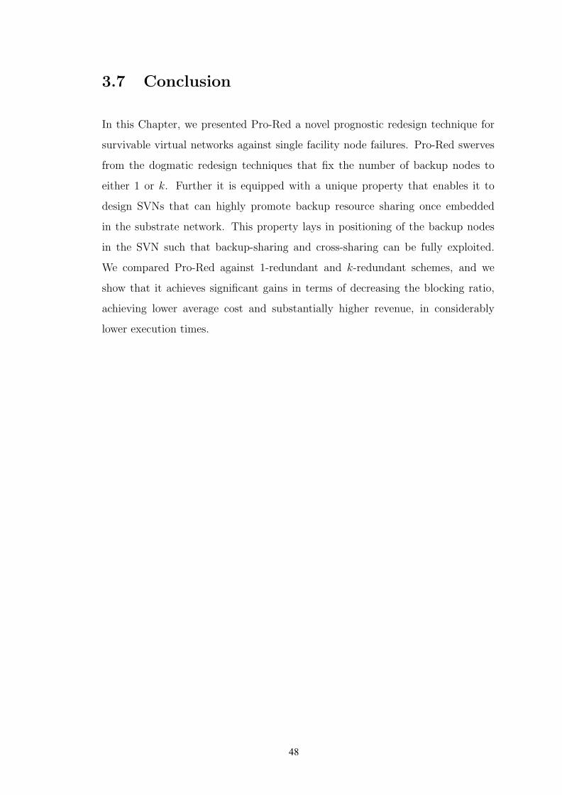
3.7 Conclusion
In this Chapter, we presented Pro-Red a novel prognostic redesign technique for
survivable virtual networks against single facility node failures. Pro-Red swerves
from the dogmatic redesign techniques that fix the number of backup nodes to
either 1 or k. Further it is equipped with a unique property that enables it to
design SVNs that can highly promote backup resource sharing once embedded
in the substrate network. This property lays in positioning of the backup nodes
in the SVN such that backup-sharing and cross-sharing can be fully exploited.
We compared Pro-Red against 1-redundant and k-redundant schemes, and we
show that it achieves significant gains in terms of decreasing the blocking ratio,
achieving lower average cost and substantially higher revenue, in considerably
lower execution times.
48
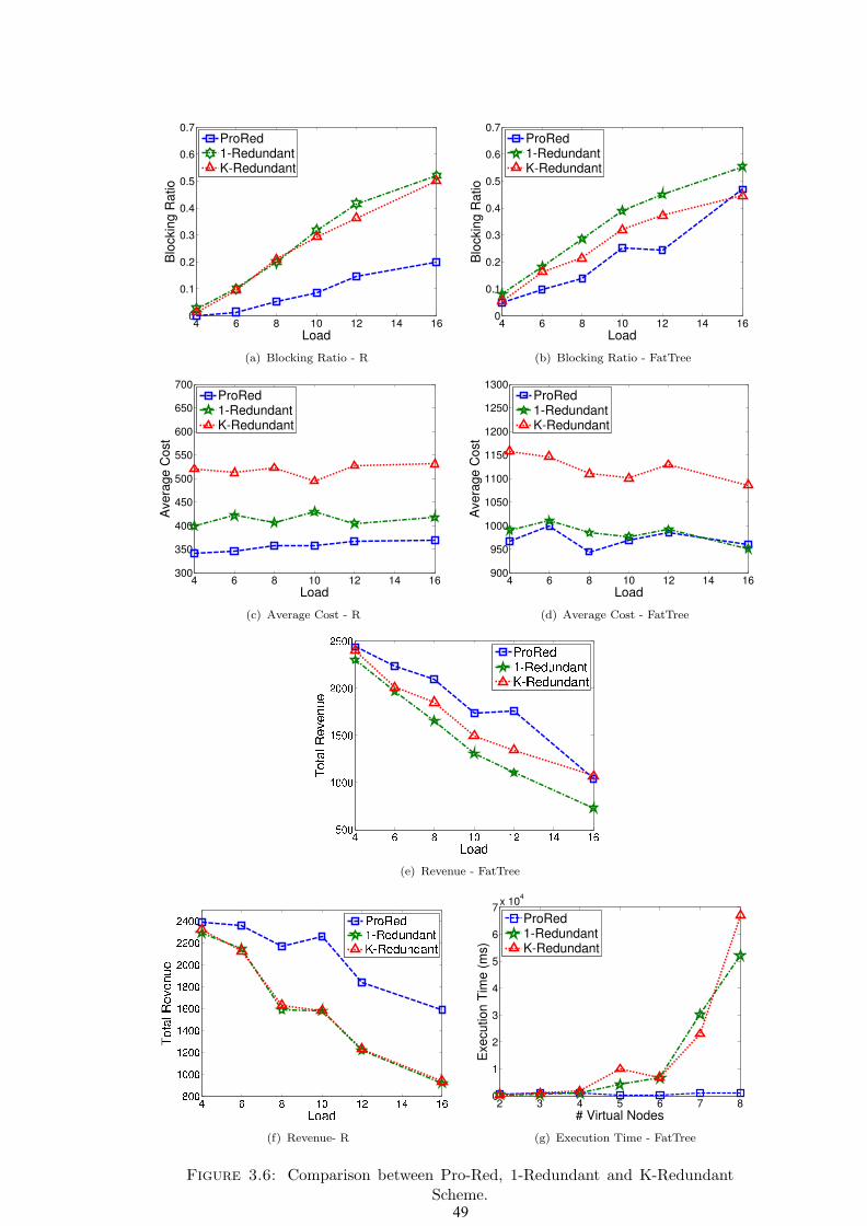
4 6 8 10 12 14 160
0.1
0.2
0.3
0.4
0.5
0.6
0.7
Load
Blo
ckin
g R
atio
ProRed1-RedundantK-Redundant
(a) Blocking Ratio - R
4 6 8 10 12 14 160
0.1
0.2
0.3
0.4
0.5
0.6
0.7
Load
Blo
ckin
g R
atio
ProRed1-RedundantK-Redundant
(b) Blocking Ratio - FatTree
4 6 8 10 12 14 16300
350
400
450
500
550
600
650
700
Load
Avera
ge C
ost
ProRed1-RedundantK-Redundant
(c) Average Cost - R
4 6 8 10 12 14 16900
950
1000
1050
1100
1150
1200
1250
1300
Load
Avera
ge C
ost
ProRed1-RedundantK-Redundant
(d) Average Cost - FatTree
(e) Revenue - FatTree
(f) Revenue- R
2 3 4 5 6 7 80
1
2
3
4
5
6
7x 10
4
# Virtual Nodes
Execution T
ime (
ms)
ProRed1-RedundantK-Redundant
(g) Execution Time - FatTree
Figure 3.6: Comparison between Pro-Red, 1-Redundant and K-RedundantScheme.49
Chapter 4
Post-Failure Restoration for
Multicast Services in Data Center
Networks
4.1 Introduction
Most of the existing work on either the VNE or the SVNE does not characterize
the mode of communication among virtual machines belonging to the virtualized
service. In fact, characterizing the mode of communications in the VNs will ben-
efit the optimization of VN embedding. There are different types of VN requests
depending on the type of applications running on. Namely, One-to-one Commu-
nication VN(unicast), One-to-many Communication VN(multicast) and all-to-all
Communication VN(broadcast). VNs in different categories have different ways of
transmitting data. For instance, in a unicast VN, the a sender only sends files to a
signle receiver; whereas in multicast VN, a sender distributes the same copy of file
to a group of receiver[59]. Hence, in unicast VNs, each communication must be
delicated a set of physical paths with sufficient bandwidth capacity; however, the
routing of communications in multicast VNs may share bandwidth, as all receiver
will obtain the exact same file from the sender.
50
Therefore, embedding a multicast VN using a unicast VN mapping algorithm
will not encourage the bandwidth sharing in MVN(Multicast Virtual Network)
communications, thus not cost-efficient. Moreover, different types of VNs may
have specific requirements other than just physical resource capacity. For example,
MVNs that are running online gaming platform require the same data sent by
source node, to be delivered to all terminals within a sepcific delay range, and the
delay variation of all terminals must respect a pre-defined threshold.
The rest of this Chapter is organized as follows: Section 4.2 is dedicated for
formally defining the MVN restoration problem and studying the impact of failure
on embedded MVNs in data center networks. In Section 4.3, we propose a path-
convergence for restoring source node failure. Section 4.4 presents our hop-to-hop
algorithm to restore a MVN against any terminal node failure. Section 4.5 is
dedicated for the numerical evaluation. We conclude this Chapter in Section 4.6.
4.2 Network Model and Problem Description
4.2.1 Network Model
In this section, we formally define the MVN Restoration problem by describing
the network environment and the various components involved. Next, we study
the impact of failure on this service class.
(1)
s
t1
t2
(3)2
2
(1)
(a) MVN
A B
C D
(30) (40)
(20)(10)
10
1010 10
(b) Substrate
A B
C D
(30) (40)
(20)(10)
10
1010 10
s
t1
t2
(c) MVNE
Figure 4.1: Network Model
51
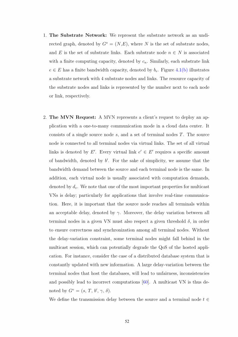
1. The Substrate Network: We represent the substrate network as an undi-
rected graph, denoted by Gs = (N ,E), where N is the set of substrate nodes,
and E is the set of substrate links. Each substrate node n ∈ N is associated
with a finite computing capacity, denoted by cn. Similarly, each substrate link
e ∈ E has a finite bandwidth capacity, denoted by be. Figure 4.1(b) illustrates
a substrate network with 4 substrate nodes and links. The resource capacity of
the substrate nodes and links is represented by the number next to each node
or link, respectively.
2. The MVN Request: A MVN represents a client’s request to deploy an ap-
plication with a one-to-many communication mode in a cloud data center. It
consists of a single source node s, and a set of terminal nodes T . The source
node is connected to all terminal nodes via virtual links. The set of all virtual
links is denoted by E ′. Every virtual link e′ ∈ E ′ requires a specific amount
of bandwidth, denoted by b′. For the sake of simplicity, we assume that the
bandwidth demand between the source and each terminal node is the same. In
addition, each virtual node is usually associated with computation demands,
denoted by dv. We note that one of the most important properties for multicast
VNs is delay; particularly for applications that involve real-time communica-
tion. Here, it is important that the source node reaches all terminals within
an acceptable delay, denoted by γ. Moreover, the delay variation between all
terminal nodes in a given VN must also respect a given threshold δ, in order
to ensure correctness and synchronization among all terminal nodes. Without
the delay-variation constraint, some terminal nodes might fall behind in the
multicast session, which can potentially degrade the QoS of the hosted appli-
cation. For instance, consider the case of a distributed database system that is
constantly updated with new information. A large delay-variation between the
terminal nodes that host the databases, will lead to unfairness, inconsistencies
and possibly lead to incorrect computations [60]. A multicast VN is thus de-
noted by Gv = (s, T , b′, γ, δ).
We define the transmission delay between the source and a terminal node t ∈
52
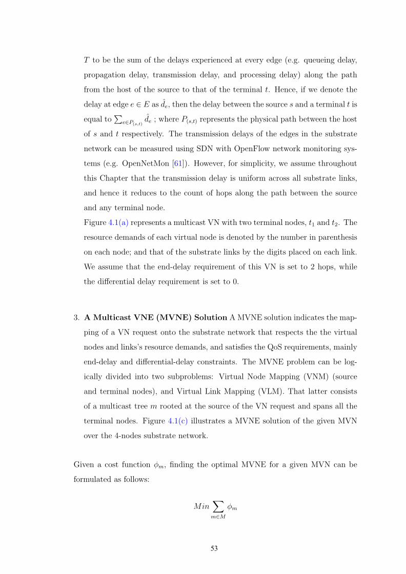
T to be the sum of the delays experienced at every edge (e.g. queueing delay,
propagation delay, transmission delay, and processing delay) along the path
from the host of the source to that of the terminal t. Hence, if we denote the
delay at edge e ∈ E as de, then the delay between the source s and a terminal t is
equal to∑
e∈P(s,t)de ; where P(s,t) represents the physical path between the host
of s and t respectively. The transmission delays of the edges in the substrate
network can be measured using SDN with OpenFlow network monitoring sys-
tems (e.g. OpenNetMon [61]). However, for simplicity, we assume throughout
this Chapter that the transmission delay is uniform across all substrate links,
and hence it reduces to the count of hops along the path between the source
and any terminal node.
Figure 4.1(a) represents a multicast VN with two terminal nodes, t1 and t2. The
resource demands of each virtual node is denoted by the number in parenthesis
on each node; and that of the substrate links by the digits placed on each link.
We assume that the end-delay requirement of this VN is set to 2 hops, while
the differential delay requirement is set to 0.
3. A Multicast VNE (MVNE) Solution A MVNE solution indicates the map-
ping of a VN request onto the substrate network that respects the the virtual
nodes and links’s resource demands, and satisfies the QoS requirements, mainly
end-delay and differential-delay constraints. The MVNE problem can be log-
ically divided into two subproblems: Virtual Node Mapping (VNM) (source
and terminal nodes), and Virtual Link Mapping (VLM). That latter consists
of a multicast tree m rooted at the source of the VN request and spans all the
terminal nodes. Figure 4.1(c) illustrates a MVNE solution of the given MVN
over the 4-nodes substrate network.
Given a cost function φm, finding the optimal MVNE for a given MVN can be
formulated as follows:
Min∑
m∈M
φm
53
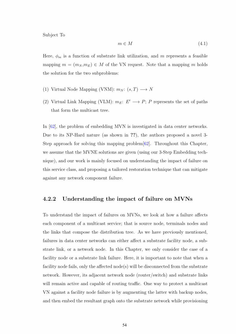
Subject To
m ∈ M (4.1)
Here, φm is a function of substrate link utilization, and m represents a feasible
mapping m = (mN ,mE) ∈ M of the VN request. Note that a mapping m holds
the solution for the two subproblems:
(1) Virtual Node Mapping (VNM): mN : (s, T ) −→ N
(2) Virtual Link Mapping (VLM): mE: E ′ −→ P ; P represents the set of paths
that form the multicast tree.
In [62], the problem of embedding MVN is investigated in data center networks.
Due to its NP-Hard nature (as shown in ??), the authors proposed a novel 3-
Step approach for solving this mapping problem[62]. Throughout this Chapter,
we assume that the MVNE solutions are given (using our 3-Step Embedding tech-
nique), and our work is mainly focused on understanding the impact of failure on
this service class, and proposing a tailored restoration technique that can mitigate
against any network component failure.
4.2.2 Understanding the impact of failure on MVNs
To understand the impact of failures on MVNs, we look at how a failure affects
each component of a multicast service; that is source node, terminals nodes and
the links that compose the distribution tree. As we have previously mentioned,
failures in data center networks can either affect a substrate facility node, a sub-
strate link, or a network node. In this Chapter, we only consider the case of a
facility node or a substrate link failure. Here, it is important to note that when a
facility node fails, only the affected node(s) will be disconnected from the substrate
network. However, its adjacent network node (router/switch) and substrate links
will remain active and capable of routing traffic. One way to protect a multicast
VN against a facility node failure is by augmenting the latter with backup nodes,
and then embed the resultant graph onto the substrate network while provisioning
54

s t1
t2
E
A B
C D
(50)
(50) (50)
(50)(0)
1010
10
10
1010 10
(a) Terminal Node Failure
s
t1
t2
E
A B
C D
(50)
(50) (50)
(50)(0)
1010
10
10
1010 10
(b) Post-Failure Restoration
s
t1
t2
E
A B
C D
(50)
(50) (50)
(50)(0)
1010
10
10
1010 10
(c) Tree Link Failure
s
t1
t2
E
A B
C D
(50)
(50) (50)
(50)(0)
1010
10
10
1010 10
(d) Tree Maintenance
Figure 4.2: Impact of a Substrate Node or Physical Link Failure
enough backup resources. As for the failure of substrate links, this can be miti-
gated by constructing an edge-disjoint backup tree. Such a scheme is commonly
known as proactive protection, since the backup nodes and links are instated prior
to any failure. While this offers a certain degree of reliability, it is also fairly costly
since the provisioned resources for these backup nodes and links remain idle until
failures occur. An alternative approach could be to restore the affected resource(s)
upon failures. Such a ”reactive approach” is more cost-efficient as it eliminates idle
resources in the network, but it may fail to find backups for the failed resource(s)
due to scarcity in the network at the moment when the failure occurred.
When a failure affects a substrate node hosting a terminal VM, the restoration
scheme necessitates finding a backup that can host the failed VM with sufficient
resources. In addition, when the failed terminal belongs to a delay-sensitive MVN,
the path used to connect the backup to the rest of the multicast tree must also
maintain the MVN’s QoS requirements; that is it must be within the end-delay
constraint, and satisfies the differential-delay with the remaining working termi-
nals. Figure 4.2(a) illustrates the case of a terminal node failure. Here, the failure
55

of substrate node C brought down terminal t1 of the 2-terminals MVN illustrated
in Figure 4.1(a). Given the substrate network’s capacity, E is the only substrate
node that has enough resources to host t1. Now to connect t1’s new host to the rest
of the MVN, the path used to reach E must be within the end-delay constraint
of 2, and satisfies the differential delay to the rest of the working terminals; the
working terminal in this case is t1. Hence, we need to connect E to the remaining
working tree with exactly 2 hops given the differential-delay constraint of 0 for the
MVN in question. Subsequently, the only feasible restoration solution in this case
is to connect E to the multicast tree via the substrate path {A-B-E}, as illustrated
in Figure 4.2(b). On the other hand, when a failure affects a substrate node host-
ing the source of a MVN, it mandates a look-up for a backup node that can host
the failed source, as well as a multicast tree reconstruction that spans all existing
terminals and respects the QoS requirements. Finally, in the event of a substrate
link failure, this latter will detach an entire subtree, thereby disconnecting one or
many terminal nodes connected via this subtree to the multicast source. Figure
4.2(c) illustrates the case where substrate link {A − B} fails, thereby detaching
the subtree rooted at B, disconnecting terminals t1 and t2.
When restoring a MVN, it is not solely sufficient to find the backup node that
maintains the service’s QoS, but it is also important to consider the cost of the
resultant tree. It is in the network provider’s best interest to minimize the embed-
ding cost of the hosted services in the aim of maximizing both his/her revenue,
as well as the network’s admissibility. For instance, after restoring terminal t1
post-failure of its original host B, the resultant tree shown in Figure 4.2(b) is
more costly than the pre-failure multicast tree of the given MVN. An alternative
solution (illustrated in Figure 4.2(d)) could be to re-route the traffic to t2 via
substrate path {A − B −D}, thereby maintaining the MVN’s QoS requirements
while achieving a lowest-cost tree. In the light of the above, we can conclude a
key observation: Multicast VN restoration demands both a service repair to re-
store the failed element, as well as a multicast tree maintenance to reconstruct the
lowest-cost tree that maintains the requested QoS.
56

4.2.3 The MVN Restoration Problem
4.2.3.1 Problem Formulation
In this section, we mathematically formulate the MVN Restoration Problem.
Given the initial MVN embedding solution and the failed node, we attempt to
find a new server for the failed node and re-connect the multicast tree with lowest
cost. Our proposed MVN restoration model achieves the following two objectives:
• MVN Repair : which consists of restoring the failed service component,
be it failure of the source node or any terminal node in the multicast tree.
• Tree Maintenance : which ensures that the MVN repair does not violate
the requested QoS, and yields a lowest-cost tree.
Our model assumes as input a substrate network, and a set of MVNE solutions
for the hosted multicast services. When a failure occurs, the restoration model is
invoked for each affected MVN in the aim to repair the affected service components,
and restore a low-cost delay-bounded multicast tree. Hence, our objective function
is presented in Equation 4.2.
Minimize∑
(i,j)∈E
t′i,j (4.2)
Here, t′i,j represents the set of substrate links that composes the restored multicast
tree. First we begin by repairing the failed terminal node using Equation 4.3.
∑
n′∈N ′
yvn,n′ = 1 ∀v ∈ T, n ∈ N (4.3)
N represents the set of failed substrate nodes, N ′ = N − N represents the set of
active substrate nodes, and yvn,n′ is a variable that denotes the relocation of failed
57

terminals. yvn,n′ is a boolean variable that indicates whether terminal node v that
was hosted on a failed substrate node n ∈ N has relocated to an active substrate
node n′ ∈ N ′. This constraint is used to ensure the embedding of the failed source
node or failed terminal node(s).
x0v,n is a boolean input that denotes the pre-failure node mapping solution of the
affected MVN. We identify the set of post-failure active virtual nodes by those
who were embedded on an unaffected substrate node n ∈ N ′. Subsequently, a
new node mapping solution will be obtained that we represent with the following
decision variable x1v,n′ .
New Node Mapping Solution :
x1v,n′ = yvn,n′ + x0
v,n′ .(1−mv) ∀v ∈ {s, T}, n ∈ N, n′ ∈ N ′ (4.4)
∑
n′∈N ′
x1v,n′ = 1 ∀v ∈ {s, T} (4.5)
∑
v∈{s,T}
x1v,n′ ≤ 1 ∀n′ ∈ N ′ (4.6)
Equation 4.4 is used to indicate the new node mapping solution. Note how yvn,n′
loops over all n ∈ N in order to fetch the new node mapping solution for failed
virtual nodes, whereas maintaining the initial embedding solution (in the case of
no migration) is restricted to the virtual nodes hosted on active substrate nodes.
Further, observe that the new node mapping solution ensures that every virtual
node in a particular MVN request is mapped on a distinct substrate node in order
to reduce the impact of failures via Equations 4.5 and 4.6. Further, it is imperative
to ensure that the new node mapping solution respects the substrate network’s
capacity constraints. Hence, we develop the following substrate nodes capacity
constraints.
58
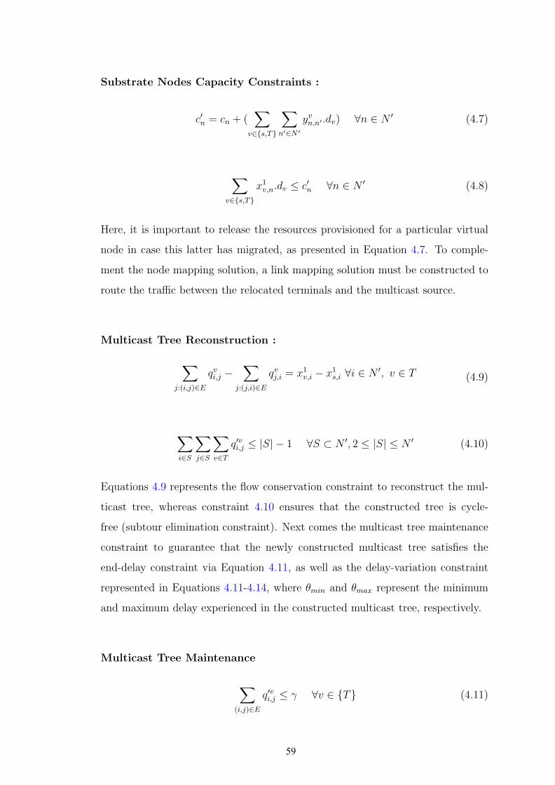
Substrate Nodes Capacity Constraints :
c′n = cn + (∑
v∈{s,T}
∑
n′∈N ′
yvn,n′ .dv) ∀n ∈ N ′ (4.7)
∑
v∈{s,T}
x1v,n.dv ≤ c′n ∀n ∈ N ′ (4.8)
Here, it is important to release the resources provisioned for a particular virtual
node in case this latter has migrated, as presented in Equation 4.7. To comple-
ment the node mapping solution, a link mapping solution must be constructed to
route the traffic between the relocated terminals and the multicast source.
Multicast Tree Reconstruction :
∑
j:(i,j)∈E
qvi,j −∑
j:(j,i)∈E
qvj,i = x1v,i − x1
s,i ∀i ∈ N ′, v ∈ T (4.9)
∑
i∈S
∑
j∈S
∑
v∈T
q′vi,j ≤ |S| − 1 ∀S ⊂ N ′, 2 ≤ |S| ≤ N ′ (4.10)
Equations 4.9 represents the flow conservation constraint to reconstruct the mul-
ticast tree, whereas constraint 4.10 ensures that the constructed tree is cycle-
free (subtour elimination constraint). Next comes the multicast tree maintenance
constraint to guarantee that the newly constructed multicast tree satisfies the
end-delay constraint via Equation 4.11, as well as the delay-variation constraint
represented in Equations 4.11-4.14, where θmin and θmax represent the minimum
and maximum delay experienced in the constructed multicast tree, respectively.
Multicast Tree Maintenance
∑
(i,j)∈E
q′vi,j ≤ γ ∀v ∈ {T} (4.11)
59

∑
(i,j)∈E
q′vi,j ≥ θmin ∀v ∈ {T} (4.12)
∑
(i,j)∈E
q′vi,j ≤ θmax ∀v ∈ {T} (4.13)
θmax − θmin ≤ δ ∀v ∈ {T} (4.14)
Finally, the newly constructed tree must also respect the substrate link’s capacity
constraints as presented below. Note if two terminals share the same substrate
link (i, j) towards the source, the bandwidth requested for the given MVN is provi-
sioned once over (i, j) since intermediate nodes in multicast trees copy-and-forward
the traffic towards the leafs.
Substrate Link Capacity Constraints
zi,j ≥ q′vi,j ∀v ∈ T, (i, j) ∈ E (4.15)
zi,jb′ − ti,j ≤ t′i,j ∀(i, j) ∈ E (4.16)
t′(i,j) ≤ be ∀e : (i, j) ∈ E (4.17)
4.2.3.2 Complexity Analysis
Given a substrate network G = (N,E) and a set of hosted MVNs denoted by M ,
the MVN Restoration problem can be formally defined as follows:
60
Problem Definition 3. When a failure affects any MVN m ∈ M , find an optimal
restoration solution for m that maintains the MVN’s end-to-end delay γ and delay-
variation constraint δ with the remaining working terminals, while achieving the
lowest-cost multicast tree.
The MVN Restoration problem is NP-Hard, since when failure occurs, the problem
becomes that of finding a Delay- and Delay-Variation Bounded Multicast Tree
(DVBMT)[63]. In the case of a source or a terminal node failure, the goal of
the DVBMT is to find the delay-constrained lowest cost tree that reconnects the
new backup node and the rest of the MVN service components (active virtual
nodes). Given the NP-Complete nature of this problem, in the next section we
propose two alternative techniques for restoring MVNs against single facility node
failure. Here, we separate the failure of terminal node from that of a source node,
since a terminal node failure only requires reconnecting the backup of the failed
terminal to the rest of the multicast tree, whereas a source node failure entails
reconstructing the entire multicast tree from the newly found source. The details
of the proposed algorithms are elucidated in the following sections. We leave for
future work the quest to mitigate against substrate links failure.
4.3 Path-Convergence Method for finding a backup
source
In this section, we propose an alternative approach for finding a backup node
upon the failure of the primary source. Our suggested approach consists of a
receiver-driven path-convergence lookup. The search begins from each terminal
node onwards; where at iteration k, all nodes at k hops from any terminal are
explored. The search persists until all the terminals converge to a single node that
satisfies the source’s resource demands, or until the maximum number of hops is
reached, which is equal to the end-delay threshold γ.
61

Algorithm 3 FindBackupSource Algorithm(Gs,Gv,M)
1: Step 1: Explores k hop neighbors2: k = 1; /*Initialize hop count to 1*/3: C = {}; /* Initialize candidate solutions list*/4: for (t ∈ T ) do5: St = t;6: end for7: while ((C 6= ∅) —— (k ≤ γ)) do8: for each (t ∈ T ) do9: S ′ = exploreAllNeighbors(St);
10: for each (w ∈ S ′) do11: if (!hasSufficientBW(P(t,w))) then12: S ′.remove(w);13: else14: if (isCandidateNode(w)) then15: Ct = Ct ∪ w
16: end if17: end if18: end for19: St = S ′;20: end for21: C = ∩k
k−δCt;22: k++;23: end while24: Return getLowestCostSolution(C);
The procedural details of the proposed method are illustrated in Algorithm 3. It
begins by initializing the hop count k to 1 and creating |T | lookup sets to store
the new nodes explored by each terminal t ∈ T . At the beginning, each set will
contain one distinct terminal node, since the search will begin from each terminal
node until they all converge to a single feasible substrate node. Next, while k is
less than the end-delay threshold δ, each terminal t will explore all neighbors at k
hops from t’s host. The substrate path used to reach any neighbor w is validated
against the bandwidth demand of the MVN. If the path’s capacity is below the
requested bandwidth, then the node will not be aggregated to the corresponding
lookup set as it will yield an infeasible link embedding solution. Similarly, a vali-
dation process is initiated at each newly-explored neighbor w to ensure that this
latter satisfies the resource demands of the source. If valid, then w will be added
to the candidate solutions set Ct explored by the corresponding terminal t. Once
62

all terminals are done exploring their neighbors at the kth hop, the set of all nodes
found between [k-δ,k] hops by each terminal are compared to find a single common
nodes. The aforementioned range guarantees that the set of paths used to reach
the backup source satisfies both end-delay and differential-delay constraints. If
multiple common nodes where found, the algorithm returns the one that yields
the lowest cost tree. The complexity of our proposed approach is O(γ.|T |.|N |).
4.4 Hop-to-Hop Terminal Finding Algorithm
In the event of a terminal node failure, a hop-to-hop terminal finding algorithm
is triggered from the source and a set of ”assisting” terminal nodes. Assisting
terminals are those that can contribute to the backup terminal lookup. Not all
terminal nodes can contribute to the search, particularly those that lie on the
bounds of a tree with a height equivalent to the end-delay threshold. Since in
this case any neighboring node will violate the end-delay constraint. The need for
foragers is to be able to find a backup for the failed terminal and connect it to
the rest of the multicast group while reusing most of the existing tree. However,
in the case of delay-sensitive applications, assisting terminals alone might fail to
find a backup; hence the need to include the source node in the backup terminal
search.
The terminal backup finding algorithm begins by finding the acceptable range
R; R being the minimum and maximum acceptable delay of the path connecting
the backup terminal to the rest of the working tree. This latter will be used to
determine the ”assisting terminals” set, as well as terminate the search on any path
that exceeds R’s upper bound. Algorithm 4 illustrates the procedure to compute
the acceptable range. Given θmin and θmax as the minimum and maximum delay
in the remaining working tree, the newly found path that will connect the backup
to the multicast group must remain in the range between θmin and θmax in order
to not violate the end-delay and differential-delay constraints of the overall tree.
However, it could be that the working tree does not exhaust the delay thresholds,
63
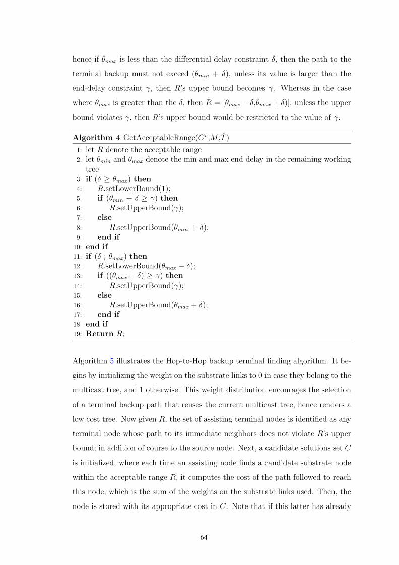
hence if θmax is less than the differential-delay constraint δ, then the path to the
terminal backup must not exceed (θmin + δ), unless its value is larger than the
end-delay constraint γ, then R’s upper bound becomes γ. Whereas in the case
where θmax is greater than the δ, then R = [θmax − δ,θmax + δ)]; unless the upper
bound violates γ, then R’s upper bound would be restricted to the value of γ.
Algorithm 4 GetAcceptableRange(Gv,M ,T )
1: let R denote the acceptable range2: let θmin and θmax denote the min and max end-delay in the remaining working
tree3: if (δ ≥ θmax) then4: R.setLowerBound(1);5: if (θmin + δ ≥ γ) then6: R.setUpperBound(γ);7: else8: R.setUpperBound(θmin + δ);9: end if10: end if11: if (δ ¡ θmax) then12: R.setLowerBound(θmax − δ);13: if ((θmax + δ) ≥ γ) then14: R.setUpperBound(γ);15: else16: R.setUpperBound(θmax + δ);17: end if18: end if19: Return R;
Algorithm 5 illustrates the Hop-to-Hop backup terminal finding algorithm. It be-
gins by initializing the weight on the substrate links to 0 in case they belong to the
multicast tree, and 1 otherwise. This weight distribution encourages the selection
of a terminal backup path that reuses the current multicast tree, hence renders a
low cost tree. Now given R, the set of assisting terminal nodes is identified as any
terminal node whose path to its immediate neighbors does not violate R’s upper
bound; in addition of course to the source node. Next, a candidate solutions set C
is initialized, where each time an assisting node finds a candidate substrate node
within the acceptable range R, it computes the cost of the path followed to reach
this node; which is the sum of the weights on the substrate links used. Then, the
node is stored with its appropriate cost in C. Note that if this latter has already
64

Algorithm 5 FindTerminalBackup Algorithm(Gs,Gv,M ,T )
1: R = GetAcceptableRange(Gv,M ,T );2: k = 1;3: Step 1: Initialize weight on substrate link4: for each (e ∈ E) do5: if (e ⊂ ME) then6: e.weight = 0;7: else8: e.weight = 1;9: end if10: end for11: Step 2: Identify the set of assisting terminal nodes12: Ss = {};13: Q = s;14: for each (t ∈ T ) do15: if (—Ps,t— + 1 ≤ R.upperBound()) then16: St = t;17: Q = Q ∪ t;18: end if19: end for20: Step 3: Begin Hop-to-Hop look-up21: while ((C 6= ∅) —— (k ≤ R.upperBound())) do22: for (each v ∈ Q) do23: S ′ = exploreAllNeighbors(Sv);24: for each (w ∈ S ′) do25: if (—P(v,w)— ⊂ R) then26: w.cost =
∑e∈P(v,w)
e.weight;
27: Cv = Cv ∪ w;28: end if29: end for30: Sv = S ′;31: end for32: C = ∪
|Q|v=1Cv;
33: k++;34: end while35: Return getLowestCostSolution(C);
65
been found, and the computed cost is lower than the one stored in C, then the
corresponding node’s cost is simply updated. The Hop-to-Hop lookup consists of
having each assisting terminal node explore its immediate neighbors iteratively
until a solution is found. When all foragers are done looking at all their neighbors
at the kth hop, the set C is checked to see if any solution is found at hop k. If
more than one solution is found, the algorithm returns the one with the lowest
cost. The hop-to-hop lookup terminates when a solution is found, or until all the
lookup paths have exceeded R’s upper bound. If we denote R’s upper bound by
K, then the complexity of our proposed algorithm is O(K.|T |.|N |).
4.5 Numerical Results
We evaluate the performance of our algorithms against the model for various met-
rics: Blocking Ratio, Restoration Ratio, Total Revenue and Execution Time. We
adopt two different substrate network topologies to conduct this evaluation. The
substrate networks used for our simulation are FatTree (K=4) [25], as it is a com-
monly deployed datacenter network. We set the CPU capacity of each host node
to 64 units, and the bandwidth capacity on the substrate links is set to 5000 units.
We perform the mapping of MVNs using the same approach as in [59] in an online
fashion, upon the arrival of each request. Hence, we assume that the VNs ar-
rival and departure follow a Poisson distribution. The VN requests are randomly
generated, where the size of each VN can range between 2 to 12 terminal nodes.
The CPU demand of the virtual nodes is set to be in the range [1:8], and the
bandwidth demand on the virtual links is in the range [10:100]. To conduct the
simulation of failures, we let one substrate node to fail periodically, and recovery
before next failure takes place. If the failed substrate node has VMs running on it,
those VMs will be disconnected from their MVNs. To restore those failed MVNs,
our algorithms and model are called after each failure. A comparison is presented
in this section using metrics like Blocking Ratio, Restoration Ratio, Total Rev-
enue and Execution Time. All results we collected are averaged over multiple runs.
66
Blocking Ratio: Blocking Ratio measures the number of failed MVN embedding
attempt over a total of 50 incoming MVN requests. In this Chapter, although both
Algorithms and model use the same embedding method initially, the restoration
process would yeild different re-mapping solutions after failures, thus resulting dif-
ferent re-embedding cost. This metric is used to test the ability to achieve low-cost
tree after failures. As shown in Figure 4.3(a), the overall trend of blocking ratio
is raising as the Poisson Load increases. Clearly our algorithms almost achieved
the same results as the model. This is due to the algorithms’ ability to reuse the
old links and explore sharing, hence, most of the time it is able to achieve optimal
or suboptimal solution. At Load 4, 8 and 10, it is estimated that our algorithms
have 5% higher blocking rate, this is because algorithms were not able to find the
lowest cost solutions in some failure cases, consquently, the available rsources were
tight compared to them of our model. Hence when new MVN requests came, some
were rejected due to the lack of resources.
Restoration Ratio: We measure the percetage of successful recovery after fail-
ures using Restoration Ratio. As we obesrve, the number of failure in one run
is usually between 50 120. At load 4 and 6, both Algorithm and model could
restore 100% of the failed MVNs. However, as load increases, we can observe the
restoration ratios for both Algorithm and model are decreasing. That’s because
the amount of available resources is limitted when the load is high. Overall, our
Algorithm is able to obtain the same level(above 98.5 %) of restoration ratio as
the model.
Execution Time: As both methods we proposed are reactive approaches, the
execution time is a crucial metric to show how fast a method can restore a failure.
If the execution of a method is too high, the disconnection time of MVN becomes
significant and put SLA at risk. In Figure 4.3(c), we can observe a dramatic
performance difference between our algorithms and model; the execution time of
algoritms ranges from 3 ms to 10 ms, whereas the model normally takes 420 ms
to 470 ms for one run, which is at most 140 times slower than the algrithms. This
67
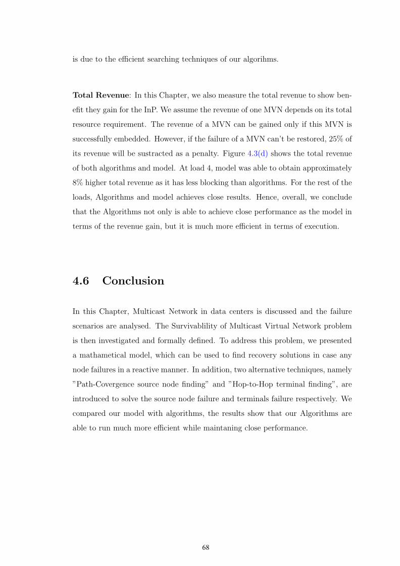
is due to the efficient searching techniques of our algorihms.
Total Revenue: In this Chapter, we also measure the total revenue to show ben-
efit they gain for the InP. We assume the revenue of one MVN depends on its total
resource requirement. The revenue of a MVN can be gained only if this MVN is
successfully embedded. However, if the failure of a MVN can’t be restored, 25% of
its revenue will be sustracted as a penalty. Figure 4.3(d) shows the total revenue
of both algorithms and model. At load 4, model was able to obtain approximately
8% higher total revenue as it has less blocking than algorithms. For the rest of the
loads, Algorithms and model achieves close results. Hence, overall, we conclude
that the Algorithms not only is able to achieve close performance as the model in
terms of the revenue gain, but it is much more efficient in terms of execution.
4.6 Conclusion
In this Chapter, Multicast Network in data centers is discussed and the failure
scenarios are analysed. The Survivablility of Multicast Virtual Network problem
is then investigated and formally defined. To address this problem, we presented
a mathametical model, which can be used to find recovery solutions in case any
node failures in a reactive manner. In addition, two alternative techniques, namely
”Path-Covergence source node finding” and ”Hop-to-Hop terminal finding”, are
introduced to solve the source node failure and terminals failure respectively. We
compared our model with algorithms, the results show that our Algorithms are
able to run much more efficient while maintaning close performance.
68
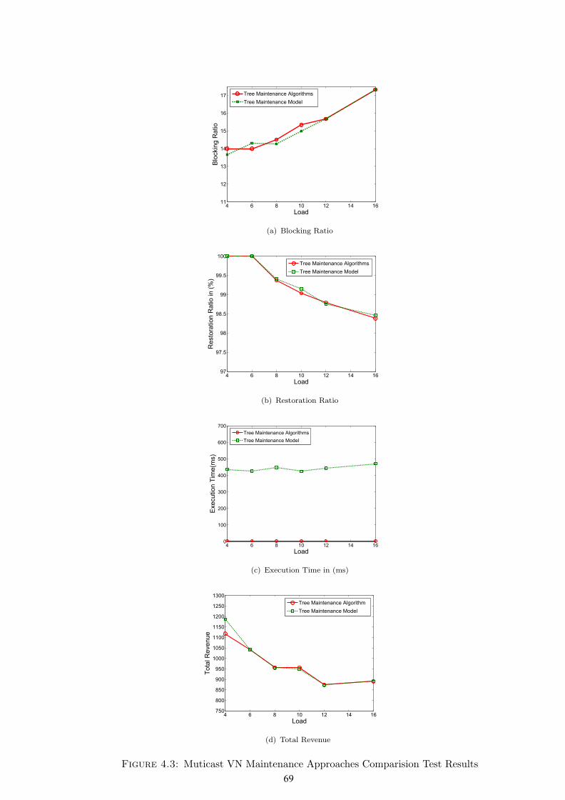
4 6 8 10 12 14 1611
12
13
14
15
16
17
LoadB
lockin
g R
atio
Tree Maintenance Algorithms
Tree Maintenance Model
(a) Blocking Ratio
4 6 8 10 12 14 1697
97.5
98
98.5
99
99.5
100
Load
Re
sto
ratio
n R
atio
in
(%
)
Tree Maintenance Algorithms
Tree Maintenance Model
(b) Restoration Ratio
4 6 8 10 12 14 160
100
200
300
400
500
600
700
Load
Exe
cu
tio
n T
ime
(ms)
Tree Maintenance Algorithms
Tree Maintenance Model
(c) Execution Time in (ms)
4 6 8 10 12 14 16750
800
850
900
950
1000
1050
1100
1150
1200
1250
1300
Load
Tota
l R
eve
nu
e
Tree Maintenance Algorithm
Tree Maintenance Model
(d) Total Revenue
Figure 4.3: Muticast VN Maintenance Approaches Comparision Test Results
69
Chapter 5
Conclusion and Future Work
5.1 Conclusion
This dissertation has explored several aspects of the survivalbility of virtual net-
work in cloud data center. Two main issues, namely the survivable VN redesign
and embedding problem, and multicast VN maintenance problem, are addressed
in Chapter 3 and Chapter 4 respectively.
In Chapter 3, the optimization problem of the survivable virtual network redesign
and embedding problem is dicussed and formally defined. The weakness of current
survivable design schemes and resource sharing techniques are illustrated via some
illustrative examples. To overcome this drawback, our prognostic VN redesign al-
gorithm is developed, along with its theoretical foundations. With the introduced
SVN embedding model in this Chapter, we compared our algorithm with the
1-Redundant and the K-Redundant schemes, and results show our algorithm out-
perform current redesign solutions inn terms of cost, addmission, execution time
and revenue.
In Chapter 4, Multicast Network in data centers is discussed and the failure sce-
narios are analysed. The Survivability of Multicast Virtual Network problem is
then investigated and formally defined. To address this problem, we presented a
70

mathematical model, which can be deployed to reactively find recovery solutions in
case of both source node failure or termial node failure. In addition, two alterna-
tive techniques, namely “Path-Covergence source node finding” and “Hop-to-Hop
terminal finding”, are introduced to solve the source node failure and terminals
failure respectively. We compared our model with our Algorithms, the results
show that our Algorithms are able to run much more efficient while maintaning
close performance.
5.2 Contributions
The contributions of this thesis are summarized as follows:
• Develped a Survivable Virtual Network Redesign Algorithm that determines
the survivable design of a VN considering sharing techniques.
• Presented a Survivable Virtual Network embedding model that optimizes
the embedding solution of a given SVN and a node mapping solution.
• Compared our redesign algorithm against the existing redesign schemes,
1-Redundant and K-Redundant. The results show our method is able to
achieve higher admission and revenue; meantime keeps the embedding cost
and execution time in a lower level.
• Introduced a mathmetical model to reactively maintain a multicast VN tree
in cloud data centers.
• Developed two novel algorithms as an alternative approach to do multicast
tree maintenance. Through the test results, our algorithms have proven to
have much less execution time but close performance compared to the model.
71
5.3 Future Work
In our future study of survivability of VN, it would be interesting to cover fail-
ure of elements into our problem for the future work. Thus far, research on
VN/SVN embedding are either seen virtual nodes as VMs, which have compu-
tation and storage resource demands, or consider the virtual topology as “Virtual
Data Center(VDC)”, which consist of VMs and network elements. To the best of
our knowledge, both assumptions share the same principle and can be protected
from failures using the same method. In “Virtual Data Center(VDC)”, VMs and
network elements are differentiated and embedded on physical servers. Similarly,
in conventional VN, even though there are only VMs, but though NFV (Network
Functions Virtualization), network elements can be virtualized on top of VMs.
With that being said, the separation of network elements and facility elements
provides InPs a better view of resources demand variation, and to achieve better
optimization of VNE. Therefore, for our future work, we would like to consider
the survivable redesign and embedding of “Virtual Data Center(VDC)”.
Regarding the work of multicast VN maintenance, we figured the drawback of
our approach, is that we can not gaurantee the restoration for all failure cases,
especially when the capacity state of the network elements is limited. In fact,
this is also a common weakness of the reactive restoration. Hence, in our future
work, we aim at finding a technique that would improve the chance of successful
restoration. As we investigated on the unsuccessful restoration cases, we found
that by enabling the migration of one or more working terminal node(s), the
multicast tree can be recovered. The following example is used to demonstrates
our statement:
Recall our 2-terminals MVN (presented in Figure 4.1(a)) hosted in a 5-nodes sub-
strate network as shown in Figure 5.1(a). The failure of terminal node t2 kicks
off a reactive look-up for a valid backup node that can assume the role of t2 and
restore the affected service. Given that the MVN in question has an end-delay re-
quirement of 2, then t2 can migrate to substrate nodes D or E while satisfying the
72

s
t1
t2
E
A B
C D
(50)
(50) (50)
(50)(50)
1010
10
10
1010
(a) No Feasible Restoration
s
t1
t2E
A B
C D
(50)
(50) (50)
(50)(50)
1010
10
10
1010
(b) Migration-Aware Restoration
Figure 5.1: Advantage of Terminal Nodes Migration
end-delay constraint. However, with the additional differential-delay constraint of
0, there are no possible ways to restore t2 while maintaining the requested QoS.
One possible solution for this problem could be to re-embed the failed MVN from
scratch. Such an approach is seemingly unpleasant as it disrupts the entire service.
A more promising solution is to encourage migrating some parts of the working
MVN to widen the search space. Figure 5.1 highlights this advantage. Clearly, by
migrating the working terminal t1 to substrate node D, it is now possible to mi-
grate the failed terminal t2 onto substrate node E and reconstruct a multicast tree
that interconnects both terminals to the source while satisfying both end-delay
and differential-delay requirements.
With the motivation of improving our algorithm, in the future work, we intend to
re-design our approach considering migrations of working terminals, we name such
approach “Migration-Aware Tree Maintenance”. We believe this new approach is
able to achieve better results in terms of restoration and total revenue.
73
Bibliography
[1] R. Griffith A. Joseph R. Katz A. Konwinski G. Lee Davidpatterson
Arielrabkin I. Stoica M. LArmbrust, A. fox and M. Zaharia. ”A View of
Cloud Computing”. 53(4):50–58, 2010.
[2] J. Caceres L. Vaquero, L. Merino and M. Lindner. ”A Break in the Clouds:
Towards a Cloud Definition”. volume 39, pages 50–55. ACM SIGCOMM
Computer Communication Review, 2009.
[3] C. Yeo R. Buyya and S. Venugopal. ”Market-Oriented Cloud Computing:
Vision, Hype, and Reality for Delivering IT Services as Computing Utilities
”. The 10th IEEE International Conference on High Performance Computing
and Communications, 2008.
[4] D. Andersen. ”Theoretical approaches to node assignment”. Computer Sci-
ence Department, page 86, 2002.
[5] Amazon Web Services. ”Amazon EC2 SLA page”. Available: http://aws.
amazon.com/ec2/sla/, 2013. Accessed: June 1, 2014.
[6] M. Rahman et al. ”Survivable virtual network embedding”. In NETWORK-
ING 2010, pages 40–52. Springer, 2010.
[7] H. Yu et al. ”Migration based protection for virtual infrastructure survivabil-
ity for link failure”. In OFC 2011. IEEE, 2011.
[8] J. Shamsi and M. Brockmeyer. ”Qosmap: Achieving quality and resilience
through overlay construction ”. 4th International Conference on Internet and
Web Applications and Services, ICIW 09, 2009.
74
[9] C. Phillips X. Zhang and X. Chen. ”An overlay mapping model for achiev-
ing enhanced qos and resilience performance”. 3rd International Congress
on Ultra Modern Telecommunications and Control Systems and Workshops
(ICUMT), 2011, 2011.
[10] H. Yu L. Li B. Dong H. Di, V. Anand and Q. Meng. ”Reliable virtual infras-
tructure mapping with efficient resource sharing”. In Communications, Cir-
cuits and Systems (ICCCAS), 2013 International Conference on, volume 1,
pages 198–202. IEEE, 2013.
[11] M. Zhani M. Rabbani and R. Boutaba. ”On achieving high survivability in
virtualized data centers”. volume E97-B, pages 10–18. IEICE Trans. Com-
mun, 2014.
[12] M. Jabri Q. Zhang, F. Zhani and R. Boutaba. ”Venice: Reliable Virtual Data
Center Embedding in Clouds”. INFOCOM, 2014.
[13] H. Yu L. Li L. Dan D. Hao, V. Anand and S. Gang. ”design of reliable
virtual infrastructure using local protection”. In Computing, Networking and
Communications (ICNC), 2014 International Conference on, pages 63–67.
IEEE, 2014.
[14] B. Guo et al. ”Survivable virtual network design and embedding to survive a
facility node failure”. Journal of Lightwave Technology, 32(3):483–493, 2013.
[15] Q. Hu et al. ”Survivable network virtualization for single facility node failure:
A network flow perspective”. Optical Switching and Networking, 10(4):406–
415, 2013.
[16] J. Xu et al. ”Survivable virtual infrastructure mapping in virtualized data
centers”. In IEEECLOUD 2012, pages 196–203. IEEE, 2012.
[17] W. Yeow et al. ”Designing and embedding reliable virtual infrastructures”.
ACM SIGCOMM Computer Communication Review, 41(2):57–64, 2011.
[18] H. Yu et al. ”Cost efficient design of survivable virtual infrastructure to
recover from facility node failures”. In ICC, pages 1–6. IEEE, 2011.
75

[19] NM. Chowdhury et al. ”Virtual network embedding with coordinated node
and link mapping”. In INFOCOM, pages 783–791. IEEE, 2009.
[20] M. Chowdhury et al. ”ViNEyard: Virtual network embedding algorithms
with coordinated node and link mapping”. TON, 20(1):206–219, 2012.
[21] T. Guo, N. Wang, K. Moessner, and R. Tafazolli. ”Shared backup network
provision for virtual network embedding”. In Communications (ICC), 2011
IEEE International Conference on, pages 1–5. IEEE, 2011.
[22] MR. Rahman and R. Boutaba. ”SVNE: Survivable virtual network embedding
algorithms for network virtualization”. 2013.
[23] M. Till Beck H. de Meer A. Fischer, JF. Botero and X. Hesselbach. ”Virtual
Network Embedding: A survey”. Communications Surveys and Tutorials,
15(4), 2013.
[24] N. Jain P. Gill and N. Nagappan. ”Understanding network failures in data
centers: measurement, analysis, and implications”. In ACM SIGCOMM Com-
puter Communication Review, volume 41, pages 350–361. ACM, 2011.
[25] NM. Chowdhury et al. ”A survey of network virtualization”. Computer
Networks, 54(5):862–876, 2010.
[26] M. Farhan Habib Biswanath Mukherjee and Ferhat Dikbiyik. ”Network
adaptability from disaster disruptions and cascading failures”. Communi-
cations Magazine, IEEE, 2014.
[27] L. Sahasrabuddhe S. Ramamurthy and B. Mukherjee. ”Survivable wdm mesh
networks”. Journal of Lightwave Technology, 21(4):870–883, 2003.
[28] V. Anand X. Liu H. Di G. Sun H. Yu, C. Qiao. ”Survivable virtual infrastruc-
ture mapping in a federated computing and networking system under single
reginal failures”. GLOBECOM, pages 1–6, 2010.
[29] K. Wolfgang H. Sandra, A. Xueli and K. Andreas. ”Path protection with
explicit availability constraints for virtual network embedding”. In Personal
76

Indoor and Mobile Radio Communications (PIMRC), 2013 IEEE 24th Inter-
national Symposium on, pages 2978–2983. IEEE, 2013.
[30] K. Vishwanath and N. Nachiappan. ”Characterizing cloud computing hard-
ware reliability”. In Proceedings of the 1st ACM symposium on Cloud com-
puting, pages 193–204. ACM, 2010.
[31] H. Yu et al. ”Survivable virtual infrastructure mapping in a federated comput-
ing and networking system under single regional failures”. In GLOBECOM
2010, pages 1–6. IEEE, 2010.
[32] M. Tornatore C. Chuah C.Meixner, F. Dikbiyik and B. Mukherjee. ”Disaster-
resilient virtual-network mapping and adaptation in optical networks”. In Op-
tical Network Design and Modeling (ONDM), 2013 17th International Con-
ference on, pages 107–112. IEEE, 2013.
[33] A.Khan S.Herker and X. An. ”Survey on Survivable Virtual Network Em-
bedding Problem and Solutions”. In ICNS 2013, The Ninth International
Conference on Networking and Services, pages 99–104, 2013.
[34] N. Jain S. Kandula C. Kim P. Lahiri D. Maltz P. Patel A. Greenberg, J. Hamil-
ton and S. Sengupta. ”VL2: a scalable and flexible data center network”. In
ACM SIGCOMM Computer Communication Review, volume 39, pages 51–62.
ACM, 2009.
[35] J. Wu S. Su D. Li, Y. Li and J. Yu. ”Esm: efficient and scalable data center
multicast routing”. 20:944–955, 2012.
[36] K. Chen at al. ”Survey on routing in data centers: insights and future direc-
tions”. Network, IEEE, 25(4):6–10, 2011.
[37] D. Li et al. ”RDCM: Reliable data center multicast”. In INFOCOM, 2011
Proceedings IEEE, pages 56–60. IEEE, 2011.
[38] J. Cao et al. ”Datacast: a scalable and efficient reliable group data delivery
service for data centers”. Selected Areas in Communications, IEEE Journal
on, 31(12):2632–2645, 2013.
77

[39] T. Chiba et al. ”Dynamic load-balanced multicast for data-intensive applica-
tions on clouds”. In CCGrid, pages 5–14. IEEE, 2010.
[40] V. Anand D.Liao, G. Sun and H.Yu. ”Efficient Provisioning for Multicast
Virtual Network under Single Regional Failure in Cloud-based Datacenters”.
KSII Transactions on Internet and Information Systems (TIIS), 8(7):2325–
2349, 2014.
[41] V. Anand D.Liao, G. Sun and H.Yu. ”Survivable provisioning for multicast
service oriented virtual network requests in cloud-based data centers”. Optical
Switching and Networking, 2014.
[42] A. Gupta el al. ”The Who, What, Why and How of High Performance Com-
puting Applications in the Cloud”. Technical report, HP Labs, Tech. Rep.,
2013.[Online]., 2013.
[43] K. Jackson et al. ”Performance analysis of high performance computing ap-
plications on the amazon web services cloud”. In In IEEE CloudCom, pages
159–168. IEEE, 2010.
[44] L. Barroso et al. ”Web search for a planet: The Google cluster architecture”.
Micro, Ieee, 23(2):22–28, 2003.
[45] S. Ghemawat et al. ”The Google file system”. In ACM SIGOPS Operating
Systems Review, volume 37, pages 29–43. ACM, 2003.
[46] T. White. ”Hadoop: the definitive guide”. O’Reilly, 2012.
[47] M. Mike. ”Multicast in the data center overview”. 2013.
[48] B. Lyles H. Kassem C. Diot, BN. Levine and D. Balensiefen. ”Deployment
issues for the ip multicast service and architecture”. Network, IEEE, 14(1):78–
88, 2000.
[49] K. Praveen A. Iyer and V. Mann. ”Avalanche: Data center Multicast using
software defined networking”. In COMSNETS, pages 1–8, 2014.
78
[50] Y. Miao et al. ”Multicast virtual network mapping for supporting multiple
description coding-based video applications”. Computer Networks, 2012.
[51] M. Zhang et al. ”Mapping multicast service-oriented virtual networks with
delay and delay variation constraints”. In GLOBECOM 2010, IEEE, pages
1–5. IEEE, 2010.
[52] U.Budnik. ”Lessons Learned from Recent Cloud Outages”. Available: http:
//www.rightscale.com/blog/enterprise-cloud-strategies/
lessons-learned-recent-cloud-outages, 2013.
[53] Y. Zhu et al. ”Algorithms for Assigning Substrate Network Resources to
Virtual Network Components”. In INFOCOM, pages 1–12, 2006.
[54] M. Yu et al. ”Rethinking virtual network embedding: substrate support for
path splitting and migration”. ACM SIGCOMM, 38(2):17–29, 2008.
[55] J. Lischka et al. ”A virtual network mapping algorithm based on subgraph
isomorphism detection”. In Proceedings of the 1st ACM workshop on Virtu-
alized infrastructure systems and architectures, pages 81–88. ACM, 2009.
[56] U. Budnik. ”Lessons Learned from Recent Cloud Outages”. Available: http:
//www.rightscale.com/blog/enterprise-cloud-strategies/
lessons-learned-recent-cloud-outages, 2013.
[57] JR. Raphael. ”The worst cloud outages of 2013”. Avail-
able:http://www.infoworld.com/slideshow/107783/
the-worst-cloud-outages-of-2013-so-far-221831, 2013.
[58] A. Medina et al. ”BRITE: An approach to universal topology generation”.
In Modeling, Analysis and Simulation of Computer and Telecommunication
Systems, 2001. Proceedings. Ninth International Symposium on, pages 346–
353. IEEE, 2001.
[59] C. Assi S. Ayoubi, K. Shaban. ”Multicast virtual network embedding in
cloud data center with end delay and delay variation constraints”. OSA/OFC
/NFOEC, 2014.
79

[60] P. Sheu et al. ”A fast and efficient heuristic algorithm for the delay-and de-
lay variation-bounded multicast tree problem”. Computer Communications,
25(8):825–833, 2002.
[61] C. Doerr N. L. M. van Adrichem and F. A. Kuipers. ”OpenNetMon: Network
Monitoring in OpenFlow Software-Defined Networks”. In Network Operations
and Management Symposium (NOMS). IEEE, 2014.
[62] Sara Ayoubi, Khaled Shaban, and Chadi Assi. ”Multicast Virtual Network
Embedding in Cloud Data Centers with End Delay and Delay Variation
Constraints”. In 7th IEEE International Conference on Cloud Computing
(CLOUD 2014). IEEE. (Accepted), 2014.
[63] George N Rouskas and Ilia Baldine. ”Multicast routing with end-to-end delay
and delay variation constraints”. In INFOCOM’96. Fifteenth Annual Joint
Conference of the IEEE Computer Societies. Networking the Next Generation.
Proceedings IEEE, volume 1, pages 353–360. IEEE, 1996.
80


