secure virtual network embedding in a multi-cloud …nuno/papers/arxiv_embedding_frv17.pdf1 secure...
TRANSCRIPT

1
Secure Virtual Network Embedding in a Multi-CloudEnvironment
Max Alaluna∗ Luıs Ferrolho∗ Jose Rui Figueira† Nuno Neves∗ Fernando M. V. Ramos∗
LaSIGE, Faculdade de Ciencias, Universidade de Lisboa, Portugal∗,CEG–IST, Instituto Superior Tecnico, Universidade de Lisboa, Portugal†
{malaluna,lferrolho}@lasige.di.fc.ul.pt, [email protected], [email protected], [email protected]
Abstract—Recently-proposed virtualization platforms give cloudusers the freedom to specify their network topologies and ad-dressing schemes. These platforms have, however, been targetinga single datacenter of a cloud provider, which is insufficient tosupport (critical) applications that need to be deployed acrossmultiple trust domains while enforcing diverse security require-ments. This paper addresses this problem by presenting a novelsolution for a central component of network virtualization –the online network embedding, which finds efficient mappings ofvirtual networks requests onto the substrate network. Our solutionconsiders security as a first class citizen, enabling the definition offlexible policies in three central areas: on the communications,where alternative security compromises can be explored (e.g.,encryption); on the computations, supporting redundancy if nec-essary while capitalizing on hardware assisted trusted executions;across multiples clouds, including public and private facilities,with the associated trust levels. We formulate the solution as aMixed Integer Linear Program (MILP), and evaluate our proposalagainst the most commonly used alternative. Our analysis givesinsight into the trade-offs involved with the inclusion of securityand trust into network virtualization, providing evidence that thisnotion may enhance profits under the appropriate cost models.
Keywords-virtual network embedding; multi-cloud; security
I. INTRODUCTION
Network virtualization has emerged as a powerful techniqueto allow multiple heterogeneous virtual networks to run overa shared infrastructure. Nowadays, a number of production-level platforms have been proposed [2, 10], already achievingthe necessary scale, performance, and required level of service.This has allowed cloud operators to start extending their serviceofferings of virtual storage and compute with network virtual-ization [10].
So far, these modern platforms have been confined to adatacenter, controlled by a single cloud operator. This restric-tion can be an important barrier as more critical applicationsstart shifting to the cloud. To overcome this problem, we aredeveloping a solution that aims to extend network virtualizationacross multiple cloud providers [3, 11], bringing a numberof benefits in terms of cost, performance, and versatility. Inparticular, a multi-cloud solution may contribute to securityfrom several perspectives. For example, a tenant1 that needsto comply with privacy legislation can demand a certain virtualmachine to remain at a specific place while the rest can go toother facilities (e.g., some services of a healthcare application,such as the analysis of patient medical images, can only beperformed in pre-approved clouds). An application can also bemade immune to any single datacenter (or cloud availabilityzone) outage by spreading its services across providers. Several
1We employ the terms user and tenant interchangeably in the paper.
incidents in cloud facilities are evidence of this increasinglyacute risk [7, 15], motivating the exploration of availability-enhancing alternatives (e.g., the services deemed critical arereplicated over two providers).
This paper tackles a fundamental component in our networkvirtualization solution – the Virtual Network Embedding (VNE)– from this new perspective. VNE addresses the problem ofprovisioning the virtual networks specified by the tenants [6].When a virtual network request (VNR) arrives, the goal isto find an effective mapping of the virtual nodes and linksonto the substrate network, while maximizing the revenue ofthe virtualization operator. This objective is subject to variousconstraints, such as the processing capacity on the substratenodes and bandwidth resource on the links.
A mostly unexplored perspective on this problem is pro-viding security assurances. We propose a VNE solution thatconsiders security constraints based on indications from thetenants. These constrains address, for instance, concerns aboutattacks on virtual machines or on physical links (e.g., re-play/eavesdropping). To further extend the resiliency proper-ties of our solution, we support the coexistence of resources(nodes/links) in multiple clouds, both public and private, andassume that each individual cloud may have distinct levels oftrust from a user standpoint. A private datacenter is in principleconsidered more trustworthy, while different public clouds mayoffer various levels of security and trust (due to their locationand/or Service Level Agreements (SLA)).
We have evaluated our proposal against the most commonlyused alternative [4]. The results show a similar behavior of bothsolutions when no security constrains are specified. Even whena significant part of the VNR impose security restrictions, theperformance decrease is limited. This is a direct consequenceof being harder to fulfill the requirements of the VNR, leadingto lower acceptance rates. A key finding is that by rising theprice of security services by a modest value, the provider isable to attain at least the same revenue as the other approach(certainly, a provider offering such added-value services willwant to increase its profits further, so that figure can be seenas a baseline).
The contributions of our work can be summarized in thefollowing: (i) We formulate the SecVNE problem and solve itas a Mixed Integer Linear Program (MILP). The novelty of ourapproach is in considering comprehensive security aspects overa multi-cloud model; (ii) We compare our solution with themost commonly used VNE MILP formulation [4], and analyzethe trade-offs between the benefit of security and embeddingefficiency.
arX
iv:1
703.
0131
3v1
[cs
.NI]
3 M
ar 2
017

2
b
c d
g
f e
j h
i
Private Cloud
Trusted Public Cloud
Public Cloud
1 2 Virtual Network
Request User Virtual Network
Substrate Network
a
Communications (virtual links)
Computations (virtual nodes)
Availability
Confidentiality & Integrity
NT0 – Container NT1 – VM NT2 – Secure VM
CT0 – Public Cloud CT1 – Trusted Public Cloud CT2 – Private Cloud
Trust Domains (clouds)
NA0 – Single virtual node NA1 – Replication (another cloud) NA2 – Replication (same cloud)
LA0 – Single path LA1 – Replicated paths
Availability
Trusted Executions
LC0 – Default LC1 – Authenticity, Integrity LC2 – Confid. & Auth., Integrity
1 2
Figure 1: Model of levels of security for communications,computations and trust domains.
II. SECURE VNE
Our approach to VNE supports the specification of securitypolicies enforced on a multi-cloud deployment, enhancing theflexibility, efficiency and security of the network virtualizationsolution. When a user wants to instantiate a virtual network(VN), besides indicating the nodes’ processing capacity and thelinks’ bandwidth, he may also include as requirements securitydemands. These demands are defined with the selection ofsecurity levels/attributes associated with resources of the VN.The current collection of attributes resulted from conversationswith several companies from the healthcare and energy sectorsthat are moving their critical services to the cloud, and theyrepresent a balance among three goals: (i) expressive enoughto represent the main security requirements when deployinga VN; (ii) easy to specify when configuring a VN (requiringa limited number of options); (iii) implementable with readyavailable technologies. Figure 1 displays the attributes that canbe selected in our virtualization solution:
Communications. Two aspects can be tuned for each of thevirtual links: (1) the user may desire to employ standard tunnelswhile connecting certain nodes (LC0 for default security), but inothers extra safeguards may be required. Since data encryptionnormally imposes a non-negligible performance penalty, we letthe user choose if authentication and integrity protection isenough (LC1) or if confidentiality is also necessary (LC2); (2)to tolerate failures, we allow for backup paths to be setup forextra availability assurances (LA0, where only a path is createdvs. LA1, with two paths).
Computation. Virtual nodes can be embedded onto machines
with distinct support for trusted executions: containers, e.g.,Docker, have applications isolated directly on top of the hostoperating system (NT0); VMs achieve a higher level of securityas isolation is ensured by the hypervisor (NT1); secure VMscould run in machines with hardware that can enhance the truston the executions (e.g., TPMs or Intel SGX extensions)2 (NT2).Since failure repair times are unpredictable [8], we also let theuser specify that a node should be replicated. He can choosethe location of each backup node, in the same cloud (NA2) ora different one (NA1) for physical failure independence.
Trust domains. The user can choose the type of cloudwhere virtual nodes should be located. Three types of cloudsare supported: public clouds, belonging to external providers(CT0); trusted public clouds that give higher security assurances(e.g., greater penalties for SLA violations) (CT1); and privateclouds, where the user has higher control on security (CT2).With these options, the user may choose private clouds for moresensitive VMs, leaving the others for public clouds to scale out.
Taking into consideration the above features, we now definethe Secure Virtual Network Embedding (SecVNE) problem:
SecVNE problem: Given a virtual network GV with therequested resources and corresponding security requirements,and the substrate network GS with the resources to serveincoming VNRs, can GV be mapped to GS with the minimumuse of resources while satisfying the following constraints?(i) Each virtual link is mapped to the substrate networkmeeting the bandwidth and security constraints, namely relatedto confidentiality, integrity and availability; (ii) Each virtualnode is mapped to the substrate network meeting the CPUcapacity and security constraints, namely with regard to trustedexecutions and availability; (iii) Each virtual node is mapped toa substrate node located in a cloud that covers its trust domainsrequirements.
Our solution handles the SecVNE problem, trying to mapa VN onto a substrate network (SN) while respecting all therequirements and constraints. When a VNR arrives, the bestmapping is searched for to decrease the costs of embedding(i.e., reduce the total quantity of substrate resources allocatedto it). If there is no possible solution to embed the incomingVN, then the request is rejected. Otherwise, the quantity ofresources demanded by the VN is allocated.
In our formulation, after the embedding of a VN, the SN isaugmented with the virtual nodes that were embedded. Thesevirtual nodes have meta-links to the substrate nodes on whichthey are mapped. Figure 2(c), illustrates the result of embeddingthe VNR presented in 2(b) onto the SN presented in 2(a). Inthe example, the VNR requires the replication of nodes andlinks for higher availability. Virtual node 1 has a meta-link withsubstrate node A, and virtual node 2 has one with E, which aretheir primary nodes. They also have meta-links with substratenodes B and D, the backup nodes that can be used when afailure occurs. In this figure it is also possible to observe thatthe substrate paths (both working and backup) correspond tomore than one substrate link (e.g., the substrate links (A,F) and(F,E) are assigned to the working path).
2Notice that we target also private clouds, where this support can be madereadily accessible. Public clouds may have this sort of offering in the future,as out-of-the-box Intel CPUs already support SGX extensions.

3
Figure 2: (a) Substrate network; (b) Virtual network request thatrequires node/path replication. (c) Example of the embeddingresult after the execution of our MILP formulation.
A. Network Model
This section describes the characteristics and attributes thatare associated to a substrate and a virtual network.
1) Substrate Network
We model the substrate network as a weighted undirectedgraph. It is denoted by GS = (NS , ES , ASN , A
SE) , where NS
is the set of substrate nodes, ES is the set of substrate links,ASN is the set of attributes of substrate nodes, and ASE is theset of attributes of substrate links.ASN contains the following attributes for substrate nodes:
ASN = {{cpuS(n), secS(n), cloudS(n)}|nεNS}• cpuS(n) - Total CPU capacity of the substrate node n.
This attribute can take any values greater or equal to 0;• secS(n) - Security provided by the substrate node n. This
attribute can take any positive value (including zero). Inthe example given in Figure 1, if substrate node n is anormal container, then secS(n) = 0. If it is a normal VMor a secure VM, then secS(n) is 1 or 2 respectively.
• cloudS(n) - Defines in which type of cloud the substratenode n is located. This attribute can take any positive value(including zero). In the example, if n is located in a publiccloud, then cloudS(n) = 0. If it is located in a trustedpublic cloud, then cloudS(n) = 1. Lastly, if n is locatedat a private cloud, then cloudS(n) = 2.
ASE contains the following attributes for substrate links:
ASE = {{bwS(l), secS(l)}|lεES}• bwS(l) - Total bandwidth capacity of the substrate link l.
This attribute can take any values greater or equal to 0;• secS(l) - Security provided by the substrate link l. This
attribute can take any positive value (including zero). Inthe example, secS(l) = 0 if substrate link l might be con-figured with no security mechanisms (defined as default).If link l supports protocols that provide authenticity andintegrity guarantees, then secS(l) = 1. Lastly, if l ad-ditionally offers confidentiality assurances (by encryptingpackets), then secS(l) = 2.
2) Virtual Network Requests
VNRs are defined by the clients of the system. Similar tothe substrate network, the VNRs are also modeled as weightedundirected graphs. Each virtual network request is denoted byGV = (NV , EV , T imeV , DurV , AVN , A
VE), where NV is the
set of virtual nodes, EV is the set of virtual links, TimeV
is the arrival time of the VNR, DurV is the time period forwhich the VN is valid, AVN is the set of attributes of substratenodes, and AVE is the set of attributes of substrate links. AVNcontains the attributes demanded by virtual nodes and links,quite similar to the Substrate Network ones, except for:
• availV (n) - Defines where the backup of virtual node nshould be mapped. This attribute can take any positivevalue (including zero). Considering the same example, ifreplication is not needed for the VNR , then availV (n)= 0. If virtual node n should have a backup in the samecloud, then availV (n) = 1. Finally, if n should have abackup located in other cloud (e.g., in order to survivefrom a cloud outage), then availV (n) = 2.
3) Measurement of Substrate Network Resources
The residual capacity (or available capacity) of a substratenode, RN (nS), is defined as the available CPU capacity ofthe substrate node nSεNS .
RN (nS) = cpuS(nS)−∑∀nV ↑nS
cpuV (nV ),
where nV εNV and x ↑ y denotes that the virtual node x ishosted on the substrate node y.
Similarly, the residual capacity of a substrate link, RE(eS),is defined as the total amount of bandwidth available on thesubstrate link eSεES .
RE(eS) = bwS(eS)−
∑∀eV ↑eS
bwV (eV ),
where eV εEV and x ↑ y denotes that the flow of the virtuallink x traverses the substrate link y.
Since a virtual link can be mapped onto multiple substratelinks, i.e., mapped onto a substrate path, it is also important todefine the available bandwidth capacity of a substrate path P.This corresponds to the minimum available bandwidth amongall the substrate links belonging to P.
RE(P ) = mineSεP
RE(eS)
4) Objectives
One of the main goals of VNE is to maximize the profitof the virtualization provider. For this purpose, and similar to[4, 17], the revenue of accepting a VNR is proportional to theacquired resources. However, in our case, we have to take intoconsideration that stronger security protection measures maybeare charged at a higher premium value:
R(GV ) = λ1∑
eV εEV
bwV (eV ) secV (eV ) +
λ2∑
nV εNV
cpuV (nV ) secV (nV ) cloudV (nV ),
where λ1 and λ2 are weight coefficients that denote the relativeproportion of each revenue component to the total revenue.
Although the revenue gives us an idea of how much avirtualization provider will gain by accepting a certain VNR,it is also important to understand the cost the provider willincur for embedding that request. The cost of embedding aVNR is proportional to the total sum of substrate resources

4
allocated to that VN. In particular, this cost has to take intoconsideration that virtual links may be embedded to one ormore physical links. In our work, the cost may also increaseif the VNR requires higher security for its virtual nodes andlinks. We define the cost of embedding a VNR as:
C(GV ) = λ1∑
eV εEV
∑eSεES
feV
eS secS(eS) +
λ2∑
nV εNV
∑nSεNS
cpunV
nS secS(nS) cloudS(nS),
where feV
eS denotes the total amount of bandwidth allocatedon the substrate link eS for virtual link eV . Similarly, cpun
V
nS
corresponds to the total amount of CPU allocated on thesubstrate node nS for virtual node nV (either working orbackup parts). As above, λ1 and λ2 are the same weights, whichdenote the relative proportion of each cost component to thetotal cost.
III. MILP FORMULATION
We have developed a MILP formulation to solve the SecVNEproblem. This section starts by explaining the decision variablesused in our formulation, the objective function, and finally theconstraints that were defined to model the problem.
A. Decision variables
Table I explains the variables that are used in our MILPformulation. Briefly, wf i,ju,v , bf i,ju,v , wli,ju,v , bli,ju,v and rlu,v arerelated to working and backup links; wni,v , bni,v and rnv areassociated with the working and backup nodes; wci,c and bci,care related to the embedding location of virtual nodes.
B. Objective Function
The objective function of our formulation has three goals: tominimize 1) the sum of all computing costs, 2) the sum of allcommunication costs, and 3) the overall number of hops of thesubstrate paths for the virtual links.
Since we have different objectives, and these objectives aremeasured in different units, we have to unify them. Thus, inour formulation we consider a weighted-sum function withthree different coefficients, β1, β2, and β3, which should bereasonably parameterized for each objective.
The first and the second parts of Eq. 1 are the sum of allworking and backup link bandwidth costs, respectively. Thethird and the fourth parts are the sum of all working and backupcomputing node costs. In this function, the level of securityprovided by the physical resources is considered. The parameterα is a weight for each physical link that assumes some valuedefined previously and that depends of (u,v) being an inter-cloud connection (link between two clouds) or an intra-domainlink (link inside a cloud). This is due to the expectation thatvirtual links that use links connecting two clouds (inter-domainlinks) will have a higher cost (monetary, delay, or other). Also,mapping a VN onto substrate resources that provide highersecurity are expected to increase costs. The fifth and last partsof the objective function achieve the third goal presented above.
Symbol Meaning
wf i,ju,v > 0
The amount of working flow, i.e., bandwidth, on thephysical link (u,v) for the virtual link (i,j)
bf i,ju,v > 0
The amount of backup flow, i.e., backup bandwidth,on the physical link (u,v) for the virtual link (i,j)
wli,ju,v ∈ {0, 1}Denotes whether the virtual link (i,j) is mapped ontothe physical link (u,v). (1 if (i,j) is mapped on (u,v), 0otherwise)
bli,ju,v ∈ {0, 1}Denotes whether the backup of virtual link (i,j) ismapped onto the physical link (u,v). (1 if backup of(i,j) is mapped on (u,v), 0 otherwise)
rlu,v > 0The reserved backup resources on a physical link (u,v),i.e., the total quantity of bandwidth that is allocated forbackup flows.
wni,v ∈ {0, 1}Denotes whether virtual node i is mapped onto thephysical node v. (1 if i is mapped on v, 0 otherwise)
bni,v ∈ {0, 1}Denotes whether virtual node i’s backup is mappedonto the physical node v. (1 if i’s backup is mappedon v, 0 otherwise)
rnv > 0The reserved backup resource on a physical node v,i.e., the total quantity of CPU that is allocated tobackups.
wci,c ∈ {0, 1}Denotes whether virtual node i is mapped on cloud c.(1 if i is mapped on c, 0 otherwise)
bci,c ∈ {0, 1}Denotes whether virtual node i’s backup is mapped oncloud c. (1 if i’s backup is mapped on c, 0 otherwise)
Table I: List of all the Domain Constraints (decision variables)used in our MILP formulation.
Intuitively, with our formulation when a VNR arrives to oursystem, the embedder will try to match the request to theresources in such a way that more “powerful” resources aresaved (e.g., those with higher security levels) for the virtualresources that require them explicitly. For instance, virtualnodes with secV = 1 will be mapped onto substrate nodeswith secS = 2 if and only if there are no other substrate nodeswith secS = 1 available.
min β1∑
(i,j)εEV
∑u,vεNS
αu,v wf i,ju,v secS(u, v)
+ β1∑
u,vεNS
rlu,v secS(u, v)
+ β2∑iεNV
∑vεNS
cpuV (v) wni,v secS(v) cloudS(v)
+ β2∑vεNS
rnv secS(v) cloudS(v)
+ β3∑
(i,j)εEV
∑u,vεNS
wli,ju,v
+ β3∑
(i,j)εEV
∑u,vεNS
bli,ju,v (1)
C. Typical Constraints
Besides the Domain Constraints of Table I, in this sectionwe define the other constraints that often have to be consideredin most VNE MILP formulations.
Link Mapping for Working Traffic
Constraints 2, 3 and 4 refer to the working flow conservationconditions, which denote that the overall network flow to anode is zero, except for the source node and the sink node,respectively (i.e., no flow appears or disappears in any node,unless it is a source or a sink node).

5
∑uεNS∪NV
wf i,ju,v −∑
uεNS∪NV
wf i,jv,u = 0,∀(i, j)εEV , vεNS\{si, ti}
(2)∑vεNS
wf i,ji,v −∑vεNS
wf i,jv,i = bwV (i, j),∀(i, j)εEV
(3)∑vεNS
wf i,jj,v −∑vεNS
wf i,jv,j = −bwV (i, j),∀(i, j)εEV
(4)Eq. 5 and 6 guarantee that the working flow of a virtual link
(i, j) always departs from the correspondent working node ofi and arrives to the correspondent working node of j.
wni,v bwV (i, j) = wf i,ji,v ,∀vεNS , (i, j)εEV (5)
wnj,v bwV (i, j) = wf i,jv,j ,∀vεNS , (i, j)εEV (6)
Node Capacity Constraints
Substrate nodes can map nodes from different VNRs. Forinstance, they can be the working node corresponding to avirtual node i from a VNR x and simultaneously be thecorresponding backup node of a virtual node j from a VNRy. Considering this, for a substrate node, the total allocatedcapacity depends on the total capacity that is allocated forworking nodes, plus the total capacity that is allocated forbackup nodes, which should be less than the current capacityof the substrate node. This is represented by Eq. 7 and 8.∑
uεNV
bnu,v cpuV (u) 6 rnv,∀vεNS (7)∑uεNV
wnu,v cpuV (u) + rnv 6 RN (v),∀vεNS (8)
Link Capacity Constraints
Like substrate nodes, substrate links can also map virtuallinks from different VNRs. Eq. 9 and 10 define the allocatedlink capacity of a substrate link as the sum of the capacityallocated for the active flows and the reserved resources forbackup. The allocated capacity of a substrate link should beless than the residual capacity of that physical link.∑
(i,j)εEV
(bf i,ju,v + bf i,jv,u) 6 rlu,v,∀u, vεNS (9)
∑(i,j)εEV
(wf i,ju,v + wf i,jv,u) + rlu,v 6 RE(u, v),∀u, vεNS (10)
D. Security Constraints
Our VNE formulation includes security constraints, for boththe nodes, links, and clouds.
Node Security Constraints
The security restrictions for nodes are defined as:
wnu,v secV (u) 6 secS(v),∀uεNV , vεNS (11)
bnu,v secV (u) 6 secS(v),∀uεNV , vεNS (12)Eq. 11 guarantees that a virtual node u is only mapped to
a physical node that has an equal or higher security level thanu’s security demand. Eq. 12 ensure the same as the previous
one, but for backup nodes. This ensures, returning to our initialexample, that a secure VM from the physical infrastructure canmap virtual nodes requesting normal containers, VMs, or secureVMs, whereas a physical container can only map virtual nodesthat are looking for normal containers.
Link Security Constraints
The following equations refer to the working and the backuplink security constraints:
wli,ju,v secV (i, j) 6 secS(u, v),∀(i, j)εEV , u, vεNS (13)
bli,ju,v secV (i, j) 6 secS(u, v),∀(i, j)εEV , u, vεNS (14)
Here, it is necessary to ensure that each virtual link is mappedto one or more physical links that provide a security levelequal or higher than the security demand of the virtual link.Similarly to the previous case, a physical link that providesdefault security can only map virtual links that demand forthat low level of security, while a physical link that providesauthenticity, integrity and confidentiality guarantees can mapvirtual links with any security demand.
Cloud Security Constraints
Eq. 15 ensures that a virtual node u is mapped to a certainphysical node v only if the cloud where v is located is of a typeof equal or higher security than the type of cloud demanded bynode u. For instance, a virtual node that requires to be mappedon a public cloud may be mapped to either a public, a trustedpublic or a private cloud, considering again our example. Onthe other side, a virtual node that requires the highest level ofsecurity can only be mapped to nodes located in a private cloud.Eq. 16 guarantees the same for the backup nodes.
wnu,v cloudV (u) 6 cloudS(v),∀uεNV , vεNS (15)
bnu,v cloudV (u) 6 cloudS(v),∀uεNV , vεNS (16)
E. Availability Constraints
Finally, we define the constraints related to fault-toleranceand availability.
Link Mapping for Backup Traffic
For the backup traffic, it is necessary to define the same setof flow constraints defined for working traffic, but using thevariables bf i,ju,v and bnu,v . Constraints 17, 18 and 19 refer tothe backup flow conservation conditions, which denote that thenetwork flow to a node is zero, except for the source nodeand the sink node, respectively. wantBackup is a parameterdefined by the tenant and it assumes the value 1 if backups areneeded or the value 0 otherwise.∑
uεNS∪NV
bf i,ju,v −∑
uεNS∪NV
bf i,jv,u = 0,∀(i, j)εEV , vεNS
(17)∑vεNS
bf i,ji,v −∑vεNS
bf i,jv,i = bwV (i, j) ∗ wantBackup,∀(i, j)εEV
(18)∑vεNS
bf i,jj,v −∑vεNS
bf i,jv,j = −bwV (i, j) ∗ wantBackup,∀(i, j)εEV
(19)

6
Eq. 20 and 21 guarantee that the backup flow of a virtual link(i, j) always departs from the corresponding backup node of iand arrives to the corresponding backup node of j. Normally,the backup path only carries information of a virtual link if afailure in the working substrate path has occurred.
bni,v bwV (i, j) = bf i,ji,v ∗ wantBackup,∀vεN
S , (i, j)εEV
(20)
bnj,v bwV (i, j) = bf i,jv,j ∗ wantBackup,∀vεN
S , (i, j)εEV
(21)The equation below guarantees that the meta-links only carry
working or backup traffic to their correspondent virtual nodes.This means that, if a virtual node 1 needs to send informationto virtual node 2, the data does not need to pass through themeta-links of a virtual node 3.∑j,k!=i j,kεNV
wf j,ki,v + wf j,kv,i + bf j,ki,v + bf j,kv,i = 0,∀vεNS , iεNV
(22)
Virtual Node MappingEq. 23 and 24 state that each virtual node has to be mapped
to exactly one working node and wantBackup backup nodesin the substrate node, i.e., if wantBackup = 0, virtual nodeswill not have backup, if wantBackup = 1, virtual nodes willhave backup. For the same VN, Eq. 25 guarantees that (i) twodifferent virtual working nodes are not mapped to the samesubstrate node; and (ii) a substrate node that is the backup fora virtual node does not have any virtual working nodes on it.Eq. 26 guarantees that a substrate node can be the backup of asingle virtual node, for the same VN.∑
vεNS
wnu,v = 1,∀uεNV (23)∑vεNS
bnu,v = wantBackup,∀uεNV (24)∑uεNV
wnu,v + bnz,v 6 1,∀vεNS , zεNV (25)∑uεNV \{z}
bnu,v + bnz,v 6 1,∀vεNS , zεNV (26)
Note that we define Eq. 25 because we want to minimizethe number of virtual resources of a VN affected if a failureoccurs in a certain substrate node. Figures 3 clarifies this idea.In this example if a failure occurs in the physical node A, andnodes 1 and 2 are mapped onto it, all the virtual links will beaffected. Instead, if all the nodes of the VN are mapped ontodifferent physical nodes and the failure occurs in node A, onlythe virtual link (1,3) will be affected.
Since in our work we allow the user to choose betweenhaving no replication, replication in the same cloud or indifferent clouds, it is necessary to specify these restrictions.∑
cεC
wcu,c = 1,∀uεNV (27)∑cεC
bcu,c = wantBackup,∀uεNV (28)
wantBackup ∗ wcu,c + bcu,c 6 depV (u),∀uεNV , cεC (29)
wcu,c > bcu,c ∗ depV (u)− 1,∀uεNV , cεC (30)
Eq. 27 states that each virtual node is mapped on exactlyone cloud. Eq. 28 ensures that, when a VN needs backup(wantBackup = 1), the backup of each virtual node is mappedto exactly one cloud. Eq. 29 and 30 are restrictions that addressif a virtual node u and its correspondent backup will be on thesame cloud or in different clouds, depending on the availabilitylevel required by u (depV (u)).
Figure 3: Example of an embedding that respects the first partof eq. 25.
Eq. 31 and 32 establish a relation between the virtual andphysical nodes and the clouds (the first one related to workingnodes, and the second related with the backup nodes).∑vεNS
(wnu,v ∗ doesItBelongc,v) > wcu,c,∀uεNV , cεC (31)∑vεNS
(bnu,v ∗ doesItBelongc,v) > bcu,c,∀uεNV , cεC (32)
The aim of these equations is the following. If a virtual nodeu is mapped onto a physical node v and v belongs to cloud c(doesItBelongc,v = 1 if substrate node v belongs to cloud c,0 otherwise), then u is mapped on cloud c.
In a similar fashion, we also need restrictions to createrelationships between the variables wf, wl and wn, and bf, bland bn:
wni,v ∗ bwV (i, j) > wli,ji,v,∀(i, j)εEV , vεNS (33)
wnj,v ∗ bwV (i, j) > wli,jv,j ,∀(i, j)εEV , vεNS (34)
bwV (i, j) ∗ wli,ju,v > wf i,ju,v,∀(i, j)εEV , u, vεNS ∪NV (35)
Eq. 33 and 34 are constraints that ensure that if a meta-link isestablished between a virtual node i and a physical node v, thenit means that i is mapped onto v. For instance, if wli,ji,v = 1,then wni,v = 1. Eq. 35 ensures that if there is a flow betweennodes u and v for a virtual link (i,j), then this means that (i,j)is mapped to a meta-link or a physical link whose end-pointsare u and v. For example, if wf i,ju,v = 1, then wli,ju,v = 1.
Eq. 36, 37 and 38 achieve the same goals as before, but forthe backup:
bni,v ∗ bwV (i, j) > bli,ji,v,∀(i, j)εEV , vεNS (36)
bnj,v ∗ bwV (i, j) > bli,jv,j ,∀(i, j)εEV , vεNS (37)
bwV (i, j) ∗ bli,ju,v > bf i,ju,v,∀(i, j)εEV , u, vεNS ∪NV (38)
Finally, we include two binary constraints to guarantee thesymmetric property of the binary variables related with links.

7
wli,ju,v = wli,jv,u,∀(i, j)εEV , u, vεNS ∪NV (39)
bli,ju,v = bli,jv,u,∀(i, j)εEV , u, vεNS ∪NV (40)
Nodes and Links Disjointness
Since any substrate nodes and links of a working pathcan fail, we have to ensure that backup paths connecting thebackups of the virtual nodes are disjoint from the substrateresources that are being used for the working part (otherwisea backup path can be compromised if a physical resourcebelonging to the working and backup part fails).
BigConstant ∗ workingu >∑vεNS
wli,ju,v,∀(i, j)εEV , uεNS
(41)
BigConstant ∗ backupu >∑vεNS
bli,ju,v,∀(i, j)εEV , uεNS
(42)
backupu = 1− workingu,∀uεNS
(43)Equations 41 to 43, together with Eq. 25, ensure path
disjointness between the working and the backup parts. As wealready observed, Eq. 25 ensures that a substrate node mappingthe working virtual node can not be a backup of any other node,and vice-versa. Relatively to Equations 41 to 43 we ensure thatif a substrate node u is an end point of a certain link that isbeing used as a working resource, u can not be an end pointof a link that is being used as a backup resource, and vice-versa. Variables working and backup are auxiliary variablesthat define if a certain physical node u belongs to the working orbackup part. BigConstant is a constant big enough to ensurethat the restriction is valid when its rightmost part is greaterthan 0.
IV. EVALUATION
This chapter presents performance results of our solution.We have implemented a simulator to reproduce an environmentwhere VNRs with different requirements arrive over time.Section IV-A presents the simulation setup. In Section IV-B wedescribe the different experiments and also briefly introduce thealgorithm that was the basis for comparison. Finally, in SectionIV-C we present the evaluation results and discuss them.
A. Simulation Setup
We have implemented an event simulator to evaluate theperformance of our algorithm. Our tool was based on theimplementation presented in [1, 4] and, in short, it simulatesthe dynamic arrival of VNRs to the system.
For the evaluation, the SN topology was randomly generatedwith 25 nodes using the GT-ITM tool [18] in (10x10) grids.Each pair of substrate nodes was randomly connected withprobability between 0.1 and 0.3. The CPU and bandwidthresources of the substrate nodes and links were real numbersuniformly distributed between 50 and 100. We assumed thatVNRs arrivals (TimeV ) are modeled as a Poisson process withan average rate of 4 VNRs per 100 time units, each one havingan exponentially distributed lifetime (DurV ) with an averageof µ = 1000 time units. In each VNR, the number of virtualnodes was randomly determined by a uniform distribution
Notation Algorithm descriptionD-ViNE VNE MILP model presented in [4]NoSec Our SecVNE with no security requirements for VN and SN
SecL+0 SecVNE with all VNRs having security requirements (excludingavailability) for 1/3 of their resources (nodes and links)
SecH+0 Similar to SecL+0, but with security requirements (excluding avail-ability) for 2/3 of the resources
SecL+5SecVNE with all VNRs having security requirements (excludingavailability) for 1/3 of their resources. In addition, 5% of the re-quests require one replica of each resource for increased availability
SecH+5 Similar to SecL+5, but with security requirements (excluding avail-ability) for 2/3 of the resources
SecL+10 Similar to SecL+5, but 10% of the requests require one replicaSecH+10 Similar to SecL+10, but with security requirements (excluding
availability) for 2/3 of the resourcesSecL+20 Similar to SecL+5, but 20% of the requests require one replicaSecH+20 Similar to SecL+20, but with security requirements (excluding
availability) for 2/3 of the resources
Table II: Configurations evaluated
between 2 and 4. Each pair of virtual nodes was randomlyconnected with probability between 0.1 and 0.3. The CPU andbandwidth capacity requirements of the virtual nodes and links,respectively, were real numbers uniformly distributed between10 and 20. We chose to only address a small scale environment(25 nodes to the SN and 2-4 nodes to the VNs) because optimalsolutions, such as the MILP used in SecVNE, do not scale forlarge networks. One way to deal with this problem is to deviseheuristics, something we leave for future work.
For SecVNE, it is necessary to include security requirements.In the simulation, the substrate nodes were divided betweenthree clouds, each one with a different security level (public,trusted public and private). The parameters sec and cloudwere set in increasing order of security with the values {1.0,1.1, 1.2}. The rationale for these values was to find a goodadjustment of the different security levels to their price. Forexample, a higher level of security is considered 20% moreexpensive than having no security. The choice of these specificvalues was based on an empirical analysis we performed on thepricing schemes of Amazon EC2. The probability of substratenodes and links having secS = 1.0 was 0.05, secS = 1.1 was0.4, and secS = 1.2 was 0.55. The weight (α) of all substratelinks was 1. The cloudV of the virtual nodes was distributeduniformly by the three different cloud types.
For the variables γ1, γ2, γ3 to be parameterized appropriately,it is necessary to consider:
γ1 ∈ ]0, 1[,γ2 ∈ ]0, 1[,γ3 ∈ ]0, 1[,
γ1 + γ2 + γ3 = 1 [14]As such, in our evaluation we considered that γ1 = 1/3,
γ2 = 1/3 and γ3 = 1/3 to find one supported Pareto solution.To solve the MILP, we used the open source library GLPK
[9]. The simulation ran for 50000 time units, and during thisperiod the MILPs tried to embed 1000 VNRs. The order ofarrival of VNRs and the capacity requirements of each VNRwere the same for both algorithms, ensuring that both solvedequivalent problem instances.
B. Evaluation Method
In our evaluation, we compared the algorithm D-ViNE [4]with ours, SecVNE. D-ViNE was chosen because it has beenconsidered as the baseline for most VNE work and due toits availability as open-source software. D-ViNE requirements

8
(a) (b) (c)
Figure 4: Performance results: (a) VNR acceptance ratio over time; (b) Time average of generated revenue; (c) Average cost ofaccepting VNRs over time.
(a) (b)
Figure 5: Performance results: (a) Average node utilization; (b)Average link utilization.are only based on CPU and bandwidth capacities, while ouralgorithm adds to these requirements also security demands, in-cluding availability needs, and cloud preferences. Furthermore,the comparison of SecVNE against D-ViNE is interesting inorder to understand what are the implications of introducingsecurity constraints on a traditional embedding problem. Theobjective function of D-ViNE is presented in Eq. 44:
min∑uvεES
αuvRE(u, v) + δ
∑i
f iuv+∑wεNS
βwRN (w) + δ
∑mεNS′\NS
xmwc(m) (44)
Besides the minimization of CPU and bandwidth resourcesallocated to a VN (i.e., minimization of costs), the objectivefunction also tries to balance the load by introducing weights.
For evaluation, we run nine different setups of our algorithm,reflecting alternative needs of the tenants. Table II summarizesthe various setups and includes the notations used to refer tothe experiments.
C. Evaluation Results
We used several performance metrics (the same as in [4]) forevaluation in our experiments. Namely, we have considered:• VNR acceptance ratio: the percentage of requests accepted
over time;• Average revenue: the revenue that the infrastructure
provider obtains over time;• Average cost of accepting a VNR: the cost the provider
will incur by embedding a request;• Average node utilization: the load of the SN nodes over
time;• Average link utilization: the load of SN links over time.To calculate the revenue R and costs C we used the equations
presented in Section II-A4. We now present all results from thesimulations and discuss each outcome.
1) The embedding performance of SecVNE without se-curity and availability requirements is similar to theembedding performance of D-ViNE. When security andavailability are not taken into account, our algorithmperforms similar to D-ViNE, as can be seen in all figuresand it shows our baseline to be identical to the mostcommonly used VNE algorithm.
2) A richer set of features (namely, security and avail-ability) decreases the acceptance ratio. Figure 4a showsthat D-ViNE leads to a higher acceptance ratio overtime when compared with our SecVNE when the securityrequirements increase over a certain threshold. This wasexpected, as SecVNE is richer in terms of the featuresprovided (security and availability, in addition to CPU andbandwidth). Consequently, in SecVNE to accept a VNRthe number of constraints is higher and more conditionsneed to be satisfied. Interestingly, the reduction in accep-tance ratio is more pronounced when the number of VNRsrequiring availability increases (compared with the othersecurity features). This is due to the higher use of substrateresources, as more resources need to be allocated to theseVNRs.
3) A richer set of features (security and availability)increases the revenue until the point when the ac-ceptance ratio becomes too low. Figure 4b illustratesthe time average of generated revenue. When our algo-rithm is set without security and availability requirements(NoSec), it generates nearly the same revenue as D-ViNE.In this figure it is also possible to observe that all otherconfigurations generate more revenue than D-ViNE. Thisis due to security having a weight coefficient (i.e., aprice) that is considered in the revenue function (richerresources are expected to be more more expensive). Sincethe acceptance ratio is not far from those of D-ViNE, therevenue increases. It is to expect, therefore, a turning pointwhere infrastructure providers may need to increase theprice of their resources to generate a profit, as a naturalconsequence of the balance between demand and supply.
9
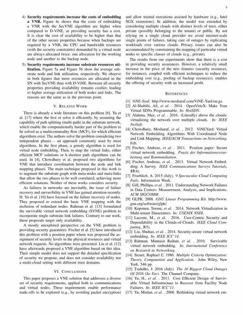
4) Security requirements increase the costs of embeddinga VNR. Figure 4c shows that the costs of embeddinga VNR with the SecVNE algorithm are higher whencompared to D-ViNE, as providing security has a cost.It is clear the cost of availability to be higher than thatof the other secure properties because when backups arerequired by a VNR, the CPU and bandwidth resources(with the security constraints) demanded by a virtual nodeare always allocated twice: one allocation for the workingnode and another to the backup node.
5) Security requirements increase substrate resources uti-lization. Figure 5a and Figure 5b show the average sub-strate node and link utilization, respectively. We observein both figures that more resources are allocated in theSN with SecVNE than with D-ViNE. Between all securityproperties providing availability remains costlier, leadingto higher average utilization of both nodes and links. Thereasons are the same as in the previous point.
V. RELATED WORK
There is already a wide literature on this problem [6]. Yu etal. [17] where the first ot solve it efficiently, by assuming thecapability of path splitting (multi-path) in the substrate network,which enable the computationally harder part of the problem tobe solved as a multicommodity flow (MCF), for which efficientalgorithms exist. The authors solve the problem considering twoindependent phases – an approach commonly used by mostalgorithms. In the first phase, a greedy algorithm is used forvirtual node embedding. Then, to map the virtual links, eitherefficient MCF solutions or k-shortest path algorithms can beused. In [4], Chowdhury et al. proposed two algorithms forVNE that introduce coordination between the node and linkmapping phases. The main technique proposed in this work isto augment the substrate graph with meta-nodes and meta-linksthat allow the two phases to be well correlated, achieving moreefficient solutions. Neither of these works considers security.
As failures in networks are inevitable, the issue of failurerecovery and survavibility in VNE has gained attention recently.H. Yu et al. [16] have focused on the failure recovery of nodes.They proposed to extend the basic VNE mapping with theinclusion of redundant nodes. Rahman et al. [13] formulatedthe survivable virtual network embedding (SVNE) problem toincorporate single substrate link failures. Contrary to our work,these proposals target only availability.
A mostly unexplored perspective on the VNE problem isproviding security guarantees. Fischer et al. [5] have introducedthis problem with a position paper where was proposed the as-signment of security levels in the physical resources and virtualnetwork requests. No algorithms were presented. Liu et al. [12]have afterwards proposed a VNE algorithm based on this idea.Their simple model does not support the detailed specificationof security we propose, and does not consider availability nora multi-cloud setting with different trust domains.
VI. CONCLUSIONS
This paper proposes a VNE solution that addresses a diverseset of security requirements, applied both to communicationsand virtual nodes. These requirements enable performancetrade-offs to be explored (e.g., by avoiding packet encryption)
and allow trusted executions assisted by hardware (e.g., IntelSGX extensions). In addition, the model was extended byconsidering multiple clouds with distinct levels of trust, eitherprivate (possibly belonging to the tenant) or public. By notrelying on a single cloud provider we avoid internet-scalesingle points of failures, taking care of outages by replicatingworkloads over various clouds. Privacy issues can also beaccommodated by constraining the mapping of particular virtualnodes to specific classes of clouds (e.g., private).
The results from our experiments show that there is a costin providing security assurances. However, a relatively smallincrease in the price of the new features (security resources,for instance), coupled with efficient techniques to reduce theembedding cost (e.g., pooling of backup resources), enablesthe offering of security with an increased profit.
REFERENCES
[1] ViNE-Yard. http://www.mosharaf.com/ViNE-Yard.tar.gz.[2] Al-Shabibi, Ali, et al. . 2014. OpenVirteX: Make Your
Virtual SDNs Programmable. In: HotSDN.[3] Alaluna, Max, et al. . 2016. (Literally) above the clouds:
virtualizing the network over multiple clouds. In: IEEENetSoft.
[4] Chowdhury, Mosharaf, et al. . 2012. ViNEYard: VirtualNetwork Embedding Algorithms With Coordinated Nodeand Link Mapping. IEEE/ACM Transactions on Networking,Feb.
[5] Fischer, Andreas, et al. . 2011. Position paper: Securevirtual network embedding. Praxis der Informationsverar-beitung und Kommunikation.
[6] Fischer, Andreas, et al. . 2013. Virtual Network Embed-ding: A Survey. IEEE Communications Surveys Tutorials,15(4).
[7] Froehlich, A. 2015 (July). 9 Spectacular Cloud ComputingFails. Information Week.
[8] Gill, Phillipa, et al. . 2011. Understanding Network Failuresin Data Centers: Measurement, Analysis, and Implications.ACM SIGCOMM.
[9] GLPK. 2008. GNU Linear Programming Kit. http://www.gnu.org/software/glpk/.
[10] Koponen, Teemu, et al. . 2014. Network Virtualization inMulti-tenant Datacenters. In: USENIX NSDI.
[11] Lacoste, M., et al. . 2016. User-Centric Security andDependability in the Clouds-of-Clouds. IEEE Cloud Com-puting, 3(5).
[12] Liu, Shuhao, et al. . 2014. Security-aware virtual networkembedding. In: IEEE ICC’14.
[13] Rahman, Muntasir Raihan, et al. . 2010. Survivablevirtual network embedding. In: International Conferenceon Research in Networking.
[14] Steuer, Raphael E. 1986. Multiple Criteria Optimization:Theory, Computation and Application. John Wiley, NewYork, 546 pp.
[15] Tsidulko, J. 2016 (July). The 10 Biggest Cloud OutagesOf 2016 (So Far). The Channel Company.
[16] Yu, H., et al. . 2011. Cost Efficient Design of Surviv-able Virtual Infrastructure to Recover from Facility NodeFailures. In: IEEE ICC’11.
[17] Yu, Minlan, et al. . 2008. Rethinking virtual network em-

10
bedding: substrate support for path splitting and migration.ACM SIGCOMM.
[18] Zegura, Ellen W., et al. . 1996. How to model aninternetwork. In: IEEE INFOCOM.