
NASA/TM-2005-212855
Structural Analysis of Helios Filament-Wound Tanks Subjected to Internal Pressure and Cooling
William L. KoNASA Dryden Flight Research CenterEdwards, California
January 2005
https://ntrs.nasa.gov/search.jsp?R=20050050955 2018-07-05T11:49:13+00:00Z

The NASA STI Program Office…in Profile
Since its founding, NASA has been dedicatedto the advancement of aeronautics and space science. The NASA Scientific and Technical Information (STI) Program Office plays a keypart in helping NASA maintain thisimportant role.
The NASA STI Program Office is operated byLangley Research Center, the lead center forNASA’s scientific and technical information.The NASA STI Program Office provides access to the NASA STI Database, the largest collectionof aeronautical and space science STI in theworld. The Program Office is also NASA’s institutional mechanism for disseminating theresults of its research and development activities. These results are published by NASA in theNASA STI Report Series, which includes the following report types:
• TECHNICAL PUBLICATION. Reports of completed research or a major significantphase of research that present the results of NASA programs and include extensive dataor theoretical analysis. Includes compilations of significant scientific and technical data and information deemed to be of continuing reference value. NASA’s counterpart of peer-reviewed formal professional papers but has less stringent limitations on manuscriptlength and extent of graphic presentations.
• TECHNICAL MEMORANDUM. Scientificand technical findings that are preliminary orof specialized interest, e.g., quick releasereports, working papers, and bibliographiesthat contain minimal annotation. Does notcontain extensive analysis.
• CONTRACTOR REPORT. Scientific and technical findings by NASA-sponsored contractors and grantees.
• CONFERENCE PUBLICATION. Collected papers from scientific andtechnical conferences, symposia, seminars,or other meetings sponsored or cosponsoredby NASA.
• SPECIAL PUBLICATION. Scientific,technical, or historical information fromNASA programs, projects, and missions,often concerned with subjects havingsubstantial public interest.
• TECHNICAL TRANSLATION. English- language translations of foreign scientific and technical material pertinent toNASA’s mission.
Specialized services that complement the STIProgram Office’s diverse offerings include creating custom thesauri, building customizeddatabases, organizing and publishing researchresults…even providing videos.
For more information about the NASA STIProgram Office, see the following:
• Access the NASA STI Program Home Pageat
http://www.sti.nasa.gov
• E-mail your question via the Internet to [email protected]
• Fax your question to the NASA STI HelpDesk at (301) 621-0134
• Telephone the NASA STI Help Desk at(301) 621-0390
• Write to:NASA STI Help DeskNASA Center for AeroSpace Information7121 Standard DriveHanover, MD 21076-1320

NASA/TM-2005-212855
Structural Analysis of Helios Filament-Wound Tanks Subjected to Internal Pressure and Cooling
William L. KoNASA Dryden Flight Research CenterEdwards, California
January 2005
National Aeronautics andSpace Administration
Dryden Flight Research CenterEdwards, California 93523-0273

NOTICE
Use of trade names or names of manufacturers in this document does not constitute an official endorsementof such products or manufacturers, either expressed or implied, by the National Aeronautics andSpace Administration.
Available from:
NASA Center for AeroSpace Information (CASI) National Technical Information Service (NTIS)7121 Standard Drive 5285 Port Royal RoadHanover, MD 21076-1320 Springfield, VA 22161-2171(301) 621-0390 (703) 605-6000
Cover art: NASA Dryden Flight Research Center, photograph ED01-0209-5.

iii
CONTENTS
Page
ABSTRACT . . . . . . . . . . . . . . . . . . . . . . . . . . . . . . . . . . . . . . . . . . . . . . . . . . . . . . . . . . . . . . . . . . . . . . . . . 1
NOMENCLATURE . . . . . . . . . . . . . . . . . . . . . . . . . . . . . . . . . . . . . . . . . . . . . . . . . . . . . . . . . . . . . . . . . . . 1
INTRODUCTION . . . . . . . . . . . . . . . . . . . . . . . . . . . . . . . . . . . . . . . . . . . . . . . . . . . . . . . . . . . . . . . . . . . . 2
FILAMENT-WOUND PRESSURE VESSELS. . . . . . . . . . . . . . . . . . . . . . . . . . . . . . . . . . . . . . . . . . . . . . 2
FINITE-ELEMENT ANALYSIS. . . . . . . . . . . . . . . . . . . . . . . . . . . . . . . . . . . . . . . . . . . . . . . . . . . . . . . . . 4Geometry . . . . . . . . . . . . . . . . . . . . . . . . . . . . . . . . . . . . . . . . . . . . . . . . . . . . . . . . . . . . . . . . . . . . . . 4Cases Analyzed . . . . . . . . . . . . . . . . . . . . . . . . . . . . . . . . . . . . . . . . . . . . . . . . . . . . . . . . . . . . . . . . . 4Finite-Element Modeling . . . . . . . . . . . . . . . . . . . . . . . . . . . . . . . . . . . . . . . . . . . . . . . . . . . . . . . . . . 4Materials . . . . . . . . . . . . . . . . . . . . . . . . . . . . . . . . . . . . . . . . . . . . . . . . . . . . . . . . . . . . . . . . . . . . . . . 5Loading. . . . . . . . . . . . . . . . . . . . . . . . . . . . . . . . . . . . . . . . . . . . . . . . . . . . . . . . . . . . . . . . . . . . . . . . 5
RESULTS. . . . . . . . . . . . . . . . . . . . . . . . . . . . . . . . . . . . . . . . . . . . . . . . . . . . . . . . . . . . . . . . . . . . . . . . . . . 6Quasi-Isotropic Tanks . . . . . . . . . . . . . . . . . . . . . . . . . . . . . . . . . . . . . . . . . . . . . . . . . . . . . . . . . . . . 6Hoop-Reinforced Tanks . . . . . . . . . . . . . . . . . . . . . . . . . . . . . . . . . . . . . . . . . . . . . . . . . . . . . . . . . . . 9Quasi-Isotropic Tanks with Aluminum Lining . . . . . . . . . . . . . . . . . . . . . . . . . . . . . . . . . . . . . . . . 10
CONCLUDING REMARKS . . . . . . . . . . . . . . . . . . . . . . . . . . . . . . . . . . . . . . . . . . . . . . . . . . . . . . . . . . . 13
FIGURES . . . . . . . . . . . . . . . . . . . . . . . . . . . . . . . . . . . . . . . . . . . . . . . . . . . . . . . . . . . . . . . . . . . . . . . . . . 14
APPENDIX: DEFORMATIONS OF A GEODESIC DOME . . . . . . . . . . . . . . . . . . . . . . . . . . . . . . . . . . 30
REFERENCES . . . . . . . . . . . . . . . . . . . . . . . . . . . . . . . . . . . . . . . . . . . . . . . . . . . . . . . . . . . . . . . . . . . . . . 33

iv

ABSTRACT
A finite-element stress analysis is performed on Helios filament-wound hydrogen tanks to examine thestress field and effect of end dome geometry on the stress field. Each tank is composed of a central circularcylindrical section with either geodesic or hemispherical end domes, which have metallic polar bosses.The tanks are subjected to combined and separate internal pressure and temperature loading conditions,and the stress contributions of each loading component are examined. The tank-wall–polar-boss interfacialmeridional tensile stress in the hemispherical dome is found to be approximately 27 percent lower than thatin the geodesic dome. The effects of both material anisotropy and the aluminum lining on the intensities oftensile meridional stress at the tank-wall–polar-boss bonding interface are examined.
NOMENCLATURE
a
radius of tank circular cylindrical section, in.
Al aluminum
b
outer radius of polar boss, in.
c
length of polar boss, in.
d
depth of tank end dome, in.
E
modulus of elasticity, lb/in
2
hoop (
θ
) modulus of elasticity, lb/in
2
meridional ( ) modulus of elasticity, lb/in
2
l
length of tank circular cylindrical section, in.
hoop panel load, lb/in.
meridional panel load, lb/in.
p
internal pressure, lb/in
2
r, z
cylindrical coordinates
t
b
thickness of polar boss wall, in.
t
s
thickness of tank wall, in.
T
temperature, ˚F
α
coefficient of thermal expansion, in/in ˚F
α
θ
hoop coefficient of thermal expansion, in/in ˚F
meridional coefficient of thermal expansion, in/in ˚F
β
helix angle, measured from the generatrix of cylinder, deg
tank wall radial displacement (in cylindrical coordinate system), in.
tank wall axial displacement in
z
-direction, in.
Poisson’s ratio
Poisson’s ratio associated with meridional ( ) and hoop (
θ
) directions
ρ
density, lb/in
3
hoop stress, lb/in
2
meridional stress, lb/in
2
EθEφ φ
NθNφ
αφ
δr
δz
ννφθ νθφ, φ
σθσφ

2
INTRODUCTION
The Helios prototype unmanned aerial vehicle (UAV), pictured on the cover of this report, is asolar-powered, ultralightweight, high-altitude (to 100,000 ft), long duration flying wing. During the daythe aircraft is powered by solar energy, and at night it is to be powered by a unique fuel cell system.This system requires lightweight tanks containing both the hydrogen and oxygen constituents of the fuelcell. Through the use of an electrolyzer, excess electrical energy, generated by the solar cells during theday, is used to disassociate water molecules. The resulting oxygen and hydrogen gases are thenaccumulated in separate tanks. At night, when the solar cells stop producing electricity, the process isreversed. The oxygen and hydrogen gases are fed into the fuel cell, which produces electricity, water,and heat. The electricity is used to power the Helios until the following morning when the solar cells takeover and the power cycle starts all over again. If this concept is successfully demonstrated, Helios flightscould last for several months and could induce a new generation of long duration aircraft calledatmospheric satellites.
Because the hydrogen tank volume is 2.25 times larger than the oxygen tank volume, weight is acritical factor for the Helios. The tanks required for both hydrogen and oxygen storage, therefore, must beas light as possible. Filament-wound pressure vessels, which are as much as 50 percent lighter thancomparable all-metal tanks, have been proposed for use as the hydrogen and oxygen gas storage tanks(refs. 1–9).
During operation, each Helios filament-wound tank (a short cylindrical section with geodesic enddomes) will be subjected to internal pressure and high-altitude cooling. As a result, the tank wall will besubjected to a biaxial tensile stress field. At the boundary of the circular cylindrical polar boss, thetension-carrying fibers cannot follow the diameter of the polar boss; they can be only tangent to the outersurface of the polar boss. Therefore, tension-carrying filaments carry the hoop stress at the boss boundary,and the interfacial meridional tensile stress (which becomes radial at the polar opening) is carried by thematrix. Because the matrix has relatively low tensile strength, the polar boss geometry must be designed toreduce the interfacial meridional tensile stress. One design approach is to develop a flanged polar boss andlap bond it to the wall of the filament-wound tank, which would transfer a portion of the meridional tensilestress into shear stress. This approach could eliminate potential leakage or bursting near thetank-wall–polar-boss bonding region. This approach was used in the preliminary design of scale modeltanks. During the proof tests, however, a gas leakage occurred at the polar boss and composite bondingregion, resulting in a tank burst initiated at the polar boss region. Therefore, a thorough understanding ofthe structural behavior of filament-wound pressure vessels with polar boss openings is crucial.
A finite-element stress analysis has been performed on proposed Helios filament-wound hydrogentanks to examine the stress field and effect of end dome geometry on the stress field, particularly at thetank-wall–polar-boss bonding interface. Hydrogen tanks are larger and more critical than oxygen tanks.This report provides basic information concerning the structural behavior of Helios filament-woundhydrogen tanks with geodesic or hemispherical end domes.
FILAMENT-WOUND PRESSURE VESSELS
Because of high tensile strength in the fiber direction, thin filaments are good candidates for thefabrication of high strength and lightweight pressure vessels. For example, the ultimate tensile strength of
3
T-1000 carbon filaments can exceed 1,000,000 lb/in
2
(refs. 1, 2). To fully benefit from the ultrahighunidirectional strength of the filaments, however, winding the filaments in the direction of the maximumprincipal stress is essential. This task is accomplished by winding the filaments on a mandrel in such amanner that the angle of the wrap (helix angle, measured from the meridian) is in the direction of themaximum stress. During the winding of the filaments, uniform tension is applied and the filaments areimpregnated with resin. After curing, the filaments and resin will develop sufficient shear strength to attainthe high tensile strength of the fibers in the form of a composite structure. After the mandrel is removed,the resulting composite shell structure will have an exceptional strength-to-weight ratio, as much as50 percent lighter than a comparable all-metal tank (refs. 1–9).
In addition to providing a structure of high strength-to-weight ratio, this manufacturing procedureoffers other advantages. For example, the shell connection can be eliminated, and the cylindricalsection, end closures, skirt, and so forth, can be fabricated as a single unit. These integral end closuresallow the precise design of pressure cylinders of various proportions over a wide range of sizes andloading conditions.
In closed-end cylindrical pressure vessels, the ratio of hoop stress to longitudinal stress acting inthe wall is 2 to 1, but in spherical vessels, the ratio of hoop stress to meridional stress acting in the wall is1 to 1 (equal-biaxial or isotropic stress field). Thus, in metal pressure vessel design, the spherical vesselis more advantageous than the cylindrical vessel because of the isotropic stress field. In the design ofmetallic cylindrical vessels, the cylindrical wall thickness must be able to withstand the hoop stress eventhough the longitudinal stress is only one-half of the hoop stress. Because metals are essentially isotropicin strength, the product of operating pressure and volume capacity for each unit weight of material is lessfor a cylindrical vessel than for a spherical vessel for a given peak stress.
When the remarkably high unidirectional tensile strength of the filaments is used, designing afilament-wound pressure vessel to attain maximum performance efficiency is possible. For this purpose,three basic filament winding systems usually are used: longitudinal, circumferential, and helical. A helix isa geodesic of a cylindrical surface, which will turn into a straight line if the cylinder is unfolded into aplane. Longitudinal and circumferential winding systems provide only unidirectional reinforcement.The helical winding system can provide biaxial reinforcement of the vessel. For example, infilament-wound cylinders, the filament reinforcement can be oriented and proportioned so that the hoopstrength of the cylinder wall is actually twice the longitudinal strength. This orientation is accomplished bywinding the filaments at the optimal helical winding angle measuredfrom the generatrix (a straight line parallel to the longitudinal axis) of the cylindrical surface (refs. 10,11).
During the winding of an integral end dome closure for a cylindrical pressure vessel, the so-calledisotensoid dome shape is quite popular. This dome geometry is mathematically determined and looks likea modified oblate spheroid (a surface formed by the rotation of an ellipse about its minor axis).When winding over the isotensoid domed vessel under the optimal helical winding angle, the filamentswill trace a geodesic of the curved surface, and every filament, regardless of its location in the structure,is subjected to the same constant tensile stress (isotensoid) (refs. 12,13). The geodesic is a curve ofminimum length joining a pair of points on a given curvilinear surface. The geodesics of the cylindricaland spherical surfaces are the helix and great circle (the geodesic of a sphere), respectively.
Another type of mathematically determined dome geometry is the so-called planar-wound dome(refs. 12, 13), over which the winding filaments lie in the same plane. This type of dome will resist internal
β tan 1– 2 54.7356 deg== ( )

4
pressure loads without contributions from the resin; however, it is not isotensoid and is not examined inthis report. During the winding of a spherical pressure vessel, because of the isotropic stress field, theso-called circumpolar (or great circle) system can be used to cause each filament to essentially describe aperfect hoop around the sphere (ref. 9).
FINITE-ELEMENT ANALYSIS
The structural performance and resizing (SPAR) program (ref. 14) was used in the finite-elementanalysis of the hydrogen tanks. The analysis examines the stress fields induced in the hydrogen tanks,structural deformations, and the intensities of the tensile meridional stress (debonding stress) induced atthe tank-wall–polar-boss bonding interface, which is the most critical region.
Geometry
Helios hydrogen tanks (figs. 1 and 2) are filament-wound structures without metal lining. Tankdimensions are indicated in the figures. Each tank is composed of a central circular cylindrical section witheither geodesic (fig. 1) or hemispherical (fig. 2) end domes. The poles of the domes have circular polaropenings to which metallic polar bosses are bonded for the transfer of hydrogen gas.
Cases Analyzed
Two types of tank geometry were analyzed. Tank type 1, a Helios hydrogen tank with geodesic enddomes, is an oblate spheroid, which has a surface formed by the rotation of an ellipse about its minor axis(fig. 1). Tank type 2 is a Helios tank with hemispherical end domes (fig. 2). In this analysis, themultilayered filament-wound tank wall was treated as one of the following:
1. Quasi-isotropic tank, in which both the cylindrical section and end domes have quasi-isotropicwalls.
2. Hoop-reinforced tank, in which the hoop strength of the cylindrical section is doubled (that is,), and the end domes have quasi-isotropic walls.
3. Quasi-isotropic tank with lining, in which 0.014-inch-thick aluminum lining is added to thequasi-isotropic tank (case 1).
Note that the meridional (longitudinal) and hoop stress induced in thecylindrical wall section are independent of material properties. The hoop reinforcement in case 2,however, affects the tank wall radial displacement in the cylindrical section.
Finite-Element Modeling
Because of symmetry, only one-quarter of a tank was modeled. Figures 3 and 4 show thefinite-element models of the Helios hydrogen tanks with geodesic and hemispherical domes, respectively.These plots were generated from the one-quarter tank models, and the respective mirror images wereadded to form the half-tank plots. The tank and polar boss walls were modeled with a single layer ofquadrilateral combined membrane and bending elements (E43 elements). The plug at the inner or outer
Eθ 2Eφ=
σφ pa 2ts σθ pa ts⁄=,⁄=( )

5
end of the polar boss was modeled with a single layer of triangular combined membrane and bendingelements (E33 elements). Table 1 lists the size of each one-quarter tank model.
Materials
The polar boss material was either aluminum or stainless steel, which has a lower coefficientof thermal expansion than aluminum has. Table 2 lists the material properties for input to thefinite-element models.
Loading
The tanks were subjected to three loading conditions: (1) combined pressure and temperature loading(referred to as “
p + T”
loading), (2) pressure loading only (referred to as “
p
-only” loading), and(3) temperature loading only (referred to as “
T
-only” loading), in which the internal pressure,
p,
was400 lb/in
2
, and the temperature,
T, was –120 ˚F, simulating high-altitude cooling.
The interiors of the polar bosses were either pressure free (p = 0, with the polar boss inner end sealed)or pressurized (with the polar boss outer end sealed and the inner end open to a tank internal pressure ofp = 400 lb/in2).
Table 1. Size of each one-quartertank finite-element model.
Item Number
JLOC 933
E43 elements 930
E33 elements 30
Table 2. Material properties.
Composite walls (quasi-isotropic)*
Polar boss (aluminum)
Polar boss (stainless steel)†
17.42 × 10⁶ 10.5 × 10⁶ 29.00 × 10⁶
0.038 0.23 0.276
0.05984 0.101 0.282
˚F 0.75 × 10⁻⁶ 12.5 × 10⁻⁶ 5.75 × 10⁻⁶
* Carbon fiber composites.† 17-7 PH stainless steel.
E Eφ= Eθ=( ), lb/in 2
v vφθ= vθφ=( )
ρ lb/in3,
α α φ α θ = ( ) , in/in=

6
RESULTS
This section discusses the results of the finite-element stress analysis of the Helios hydrogen tanks.
Note that all figures present the data for the cases in which aluminum polar bosses were used.
Quasi-Isotropic Tanks
Figures 5–10 show the resulting deformed shapes of the two Helios hydrogen tank types with
quasi-isotropic walls (and no lining) subjected to the three loading conditions (
p + T
,
p
-only, and
T
-only).
Each figure shows the magnitude of radial displacement of the cylindrical wall (normal to the
z
-axis), ,
and the axial displacement of the polar boss (in the
z
-direction), . In all plots of the radial and axial
displacement distributions ( ), each arrow drawn normal to the tank wall contour indicates the
magnitude of and only, and should not be confused with the actual direction of or . Notice
that in the
p + T
and
p
-only loading cases (figs. 5–8), the radial displacement, , suddenly increases at the
cylinder-dome junctures, reflecting increases in the hoop stress, , at the same regions.
In the geodesic dome tank under
p + T
loading (fig. 5) the radial displacement, , is slightly
negative. It is negative because the radial displacement, , at the cylinder-dome juncture under
p
-only
loading (fig. 7) is very small (two order of magnitude smaller than at the cylindrical section) and cannot
overcome the inward radial displacement, , resulting from
T
-only loading (fig. 9). This peculiar
structural behavior (that is, negligible radial displacement at the cylinder-dome juncture) occurs because
the geodesic dome, under internal pressure, tends to deform into a hemispherical shape, and the bending
effect tends to constrain the juncture to move outward, resulting in very small at the juncture. This
structural behavior is examined in the Appendix through the use of an isolated geodesic dome subjected
to
p
-only loading. In the hemispherical dome tank (figs. 6, 8, 10), this peculiar structural behavior at the
cylinder-dome juncture does not occur. In the
T
-only loading cases (figs. 9,10), the dome polar region
bends inward because of the shrinkage of the metallic polar bosses.
Figures 11 and 12 show the meridional distributions of tank wall axial displacement, , for the two
types of dome geometry. The polar region axial displacement, , of the hemispherical dome is roughly
50 percent that of the geodesic dome under the
p + T
and
p
-only loading conditions.
The effect of
T
-only loading (the difference between the
p + T
and
p
-only loading curves) causes the
axial displacement of the polar boss to be less than that of the surrounding wall (
p + T
loading curves),
which is why the tank wall appears to slightly bulge in the region surrounding the polar boss (figs. 5, 6).
The effect of
T
-only loading on is very small except in the polar boss region.
Figures 13 and 14 show the meridional distributions of radial displacement, , for the two types of
dome geometry. In the geodesic dome case (fig. 13), the radial displacement, , sharply decreases and
becomes slightly negative at the cylinder-dome juncture. In the hemispherical dome case (fig. 14), the
value of decreases to one-half at the cylinder-dome juncture.
δrδz
δr δz,
δr δz δr δzδr
σθ
δrδr
δrδr
δr
δzδz
δz
δrδr
δr

7
Table 3 lists the displacement of the quasi-isotropic tank wall at critical points for the two types ofdome geometry. Two sets of data are listed; the upper rows indicate the cases in which the polar bosseswere not pressurized, and the lower rows (shown in parentheses) indicate the cases in which the polarbosses were pressurized (
p
= 400 lb/in
2
). Note that the effects of the polar boss material and internalpressure on the tank wall displacement are minuscule.
Figures 15 and 16 show the meridional distributions of meridional stress, , for the two types ofdome geometry. For the geodesic dome (fig. 15), the value of is constant in the cylindrical zone andgradually increases towards the polar boss region. For the hemispherical dome (fig. 16), is constanteverywhere except for the small region near the polar boss. The
T
-only loading tends to increase the valuesof at the tank-wall–polar-boss interface (see the
p + T
curves in figs. 15 and 16).
Table 3. Quasi-isotropic tank wall displacement at the cylindrical section, , and polar boss, .
Dome typePolar boss material
Loadingcondition
, in. (cylindrical section)
, in. (polar boss)
Geodesic Al
p
-only 0.117(0.117)
0.158(0.158)
T
-only – 0.289
×
10
–2
–0.286
×
10
–1
p + T
0.114(0.114)
0.129(0.130)
Steel
p + T
0.114(0.114)
0.143(0.144)
Hemispherical Al
p
-only 0.117(0.117)
0.0862(0.0868)
T
-only – 0.289
×
10
–2
–0.263
×
10
–1
p + T
0.114(0.114)
0.0599(0.0605)
Steel
p + T
0.114(0.114)
0.0721(0.0727)
( ) p = 400 lb/in 2 applied inside the polar bosses.
δr δz
δr δz
σφσφ
σφ
σφ

8
Figures 17 and 18 show the meridional distributions of hoop stress, , for the two types of domegeometry. For the geodesic dome (fig. 17), the value of is constant in the cylindrical zone, decreasesrapidly to nearly zero at the cylinder-dome juncture, then increases towards the polar boss region,and finally decreases slightly at the polar boss. For the hemispherical dome (fig. 18), decreases toone-half at the cylinder-dome juncture, and remains constant in the dome region except at the polar boss.The
T
-only loading considerably decreases the values of at the tank-wall–polar-boss interface (see the
p + T
curves in figs. 17 and 18).
Table 4 lists the stress induced at the polar boss locations in the quasi-isotropic tank walls undervarious loading conditions. The upper rows of data indicate the cases in which the interiors of the polarbosses were not pressurized, and the lower rows of data (shown in parentheses) indicate the cases in whichthe polar bosses were pressurized (
p
= 400 lb/in2).
Note that the meridional and hoop stress of the hemispherical dome type are 27 and 35 percent lower,respectively, than that of the geodesic dome type. Also note that changing the polar boss material fromaluminum to steel (thus lowering the coefficient of thermal expansion) and applying pressure insidethe polar boss cavity have very little effect on reducing the tank-wall–polar-boss interfacial meridionaltensile stress.
Table 4. Stress at the tank-wall–polar-boss interface for quasi-isotropic tanks.
Dome typePolar boss material
Loading condition , lb/in2 , lb/in2
Geodesic Al p-only 73,000(72,920)
64,120(64,410)
T-only 4,210 –13,580
p + T 77,21077,120
50,530(50,860)
Steel p + T 74,860(74,710)
58,280(58,650)
Hemispherical Al p-only 52,700(52,600)
46,330(46,740)
T-only 3,380 –13,240
p + T 56,070(55,970)
33,090(33,530)
Steel p + T 54,130(54,030)
40,700(41,120)
( ) p = 400 lb/in2 applied inside the polar bosses.
σθσθ
σθ
σθ
σφ σθ

9
Hoop-Reinforced Tanks
Figures 19–24 show the deformed shapes of two types of hoop-reinforced tanks under various loadingconditions. The radial displacement in the cylindrical sections decreases to approximately one-half ofthat in the quasi-isotropic tank. The geodesic dome type still exhibits the stepwise change of radialdisplacement, , at the cylinder-dome juncture under the p + T and p-only loading conditions (figs. 19and 21, respectively). In the hemispherical dome case, however, the stepwise change of radial displacement,
, completely disappears under the p + T and p-only loading conditions (figs. 20 and 22, respectively).
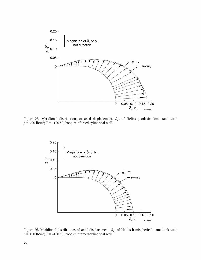
Figures 25 and 26 show the meridional distributions of tank wall axial displacement, , for the twotypes of dome geometry. The profiles are very similar to those of the quasi-isotropic tanks (figs. 11,12)except at the regions near the polar bosses.
Figures 27 and 28 show the meridional distributions of tank wall radial displacement, , for the twotypes of dome geometry. The value of in the cylindrical regions for the two cases is reduced nearlyone-half because of the hoop reinforcement (see figs. 13 and 14).
Table 5 shows the tank wall displacement data for the two types of dome geometry when the hoopstrength of the cylindrical section was doubled. The data for the quasi-isotropic tanks (from table 3) areshown in parentheses for comparison. Note that the differences between the two material types arerelatively small.
Table 5. Hoop-reinforced tank wall displacement at the cylindrical section andpolar boss, .
Dome typeLoading condition
, in. (cylindrical section)
, in. (polar boss)
Geodesic p-only 0.0576(0.117)
0.175(0.158)
T-only – 0.289 × 10⁻²
(– 0.289 × 10⁻²)–0.268 × 10⁻¹
(– 0.286 × 10⁻¹)
p + T 0.0547(0.114)
0.148(0.129)
Hemispherical p-only 0.0576(0.117)
0.0967(0.0862)
T-only – 0.289 × 10⁻²
(– 0.289 × 10⁻²)–0.249 × 10⁻¹
(– 0.263 × 10⁻¹)
p + T 0.0547(0.114)
0.0718(0.0599)
( ) Data for the quasi-isotropic tanks (from table 3).
δr
δr
δzδr
δrδr
δz
δr δz

10
The meridional distributions of meridional (figs. 29, 30) and hoop stress (figs. 31, 32) of thehoop-reinforced tanks are very similar to those of the quasi-isotropic tanks (figs. 15–18) except at thecylinder-dome junctures and the polar boss regions.
Table 6 lists the data for the interfacial stress at the tank-wall–polar-boss bonding surfaces in the twotypes of hoop-reinforced tanks. The data for the quasi-isotropic tanks (from table 4) are shown inparentheses for comparison. Note that in the p + T loading case, the interfacial meridional stress, ,decreases by merely 4 percent, and the hoop stress, , increases by roughly 25 percent, for both types ofdome geometry when the hoop strength is doubled (figs. 31, 32).
Quasi-Isotropic Tanks with Aluminum Lining
The deformed shapes of the quasi-isotropic tanks with 0.014-inch-thick aluminum lining are quitesimilar to the deformed shapes of the tanks without lining (figs. 5–10). Figures depicting the deformedshapes of these tanks, therefore, are not presented.
Table 7 compares the displacement data for the aluminum-lined quasi-isotropic tanks to thecorresponding displacement data for the tanks without lining (from table 3, shown in parentheses). Notethat the wall displacement of the aluminum-lined tanks decreases slightly compared to the walldisplacement of the corresponding quasi-isotropic tanks with no aluminum lining (table 3).
Table 6. Stress at the tank-wall–polar-boss interface in hoop-reinforced tanks.
Dome typeLoadingcondition , lb/in2 , lb/in2
Geodesic p-only 73,520(73,000)
75,830(64,120)
T-only 970(4,210)
–13,220(–13,580)
p + T 74,490(77,210)
62,610(50,530)
Hemispherical p-only 53,180(52,700)
54,290(46,330)
T-only 600(3,380)
–12,990(–13,240)
p + T 53,780(56,070)
41,300(33,090)
( ) Data for the quasi-isotropic tanks (from table 4).
σφσθ
σφ σθ

11
Table 8 lists the stress induced at the tank-wall–polar-boss interface in the aluminum-lined tanks undervarious loading conditions. The stress in the composite wall and aluminum lining are shown to comparethe stress sharing. Corresponding data for the quasi-isotropic tanks without lining (from table 4) are shownin parentheses.
Under p + T loading, the aluminum lining reduces the level of tank-wall–polar-boss interfacialmeridional stress, , by only 10 and 17 percent for the geodesic and hemispherical dometypes, respectively. Table 9 lists the interfacial panel loads ( ; stress x thickness) at thetank-wall–polar-boss interface calculated from table 8. Under p + T loading, the panel load shares for thealuminum lining are 10 and 11 percent for and , respectively, for both dome types.
Table 7. Wall displacements of aluminum-lined quasi-isotropic tanks at the cylindricalsection, , and polar boss, .
Dome type Loading condition, in.
(cylindrical section), in.
(polar boss)
Geodesic p-only 0.105(0.117)
0.134(0.158)
T-only – 0.288 × 10⁻²
(– 0.289 × 10⁻²)–0.352 × 10⁻¹
(– 0.286 × 10⁻¹)
p + T 0.102(0.114)
0.0984(0.129)
Hemispherical p-only 0.105(0.117)
0.0721(0.0862)
T-only – 0.286 × 10⁻²
(– 0.289 × 10⁻²)–0.311 × 10⁻¹
(– 0.263 × 10⁻¹)
p + T 0.102(0.114)
0.041(0.0599)
( ) Data for the quasi-isotropic tanks with no aluminum lining (from table 3).
δr δz
δr δz
σφNφ , Nθ
Nφ Nθ

12
Table 8. Stress at the tank-wall–polar-boss interface in aluminum-lined quasi-isotropic tanks.
Dome typeLoadingcondition , lb/in2 , lb/in2
Tank wall Al lining Tank wall Al lining
Geodesic p-only 65,160(73,000)
45,900 53,960(64,120)
39,000
T-only 4,170(4,210)
–5,200 –13,060(–13,580)
–13,070
p + T 69,330(77,210)
40,700 40,900(50,530)
25,930
Hemispherical p-only 43,940(52,700)
31,840 39,290(46,330)
28,490
T-only 2,500(3,380)
–5,000 –12,420(–13,240)
–12,220
p + T 46,440(56,070)
26,840 26,870(33,090)
16,270
( ) Data for the quasi-isotropic tanks with no aluminum lining (from table 4).
Table 9. Interfacial panel loads ( ) at the tank-wall–polar-boss interface in aluminum-linedquasi-isotropic tanks.
Dome typeLoadingcondition , lb/in. , lb/in.
Tank wall Al lining Tank wall Al lining
Geodesic p-only 5,148 643 4,263 546
T-only 329 –73 –1,032 –183
p + T 5,477 570 3,231 363
Hemispherical p-only 3,471 446 3,103 399
T-only 198 –70 –981 –171
p + T 3,669 376 2,122 228
σφ σθ
Nφ , Nθ
Nφ Nθ
13
CONCLUDING REMARKS
A finite-element stress analysis was performed on Helios filament-wound hydrogen tanks with twotypes of end domes. Tank deformations, stress fields, and intensities of the tensile meridional stress(debonding stress) induced at the tank-wall–polar-boss bonding interface were examined. The principalfindings are as follows:
1. The wall around the polar boss deformed with an apparent “dimple” in both the geodesic andhemispherical dome tanks because of the shrinking effect of the metallic end bosses.
2. Under pressure loading only and combined pressure and temperature loading, the inward axialdisplacement, , of the hemispherical dome tank end boss was roughly one-half that of thegeodesic dome tank end boss.
3. For both the geodesic and hemispherical dome tanks, the radial displacement, , of the tank wallwas much larger in the cylindrical wall region because of greater hoop stress, .
4. The stress field in the geodesic dome was nonequal biaxial ( ). The stress field in thehemispherical dome, however, was equal biaxial ( ) everywhere, except at thetank-wall–polar-boss interface region.
5. The meridional stress, , in the geodesic dome tank increased slightly along the meridiantowards the polar boss, and then increased considerably as the tank-wall–polar-boss interface wasapproached. In the hemispherical dome tank, however, the meridional stress, , was constantalong the meridian, except at the tank-wall–polar-boss bonding interface region.
6. The hoop stress, , in the geodesic dome tank reached infinitesimal value at the cylinder-domejuncture because of extremely small hoop expansion at the juncture site. In the hemisphericaldome tank, however, the meridional distribution of hoop stress, , did not have any“dented” regions.
7. The interfacial tensile meridional stress, , at the tank-wall–polar-boss interface of the geodesicdome tank was approximately 27 percent greater than that of the hemispherical dome tank in boththe quasi-isotropic and hoop-reinforced cases.
8. Doubling the hoop strength reduced the radial displacement but did not reduce the hoop stress inboth the geodesic and hemispherical dome tanks.
9. When the end boss material was changed from aluminum to stainless steel, which has a lowercoefficient of thermal expansion, the interfacial meridional tensile stress, , decreased by only3 percent in both dome types. Furthermore, varying the end boss material did not have mucheffect on reducing the interfacial tensile stress at the tank-wall–polar-boss interface.
10. The meridional and hoop load shares by the 0.014-inch-thick aluminum lining were approximately10 and 11 percent for the geodesic and hemispherical dome tanks, respectively.
Dryden Flight Research CenterNational Aeronautics and Space AdministrationEdwards, California, July 2, 2004
δz
δrσθ
σθ σφ≠σθ σφ=
σφ
σφ
σθ
σθ
σφ
σφ

14
FIGURES
Figure 1. Geometry of Helios hydrogen tank with geodesic domes.
Figure 2. Geometry of generic Helios hydrogen tank with hemispherical domes.
b
c
r
ts
tb
dl
a
040213
a = 20.3075 in.
b = 1.22 in.
c = 1.75 in.
d = 14.68 in.
l = 27.15 in.tb = 0.469 in.
ts = 0.079 in.
z
c
r
ts
a = 20.3075 in.
b = 1.22 in.
c = 1.75 in.
d = al = 27.15 in.tb = 0.469 in.ts = 0.079 in.
d= a
l
a
040214
btb
z
15
Figure 3. One-quarter tank finite-element model of the Helios geodesic dome tank (mirror image added toshow one-half of the tank).
Figure 4. One-quarter tank finite-element model of the Helios hemispherical dome tank (mirror imageadded to show one-half of the tank).
040215
For a one-quarter modelNumber of nodesNumber of 4-node elementsNumber of 3-node elements
99393030
040216
For a one-quarter modelNumber of nodesNumber of 4-node elementsNumber of 3-node elements
99393030

16
Figure 5. Deformed shape of Helios geodesic dome tank under internal pressure and temperature loading;
p
= 400 lb/in
2
;
T
= –120 °F.
Figure 6. Deformed shape of Helios hemispherical dome tank under internal pressure and temperatureloading;
p
= 400 lb/in
2
;
T
= –120 °F.
δr = –0.154 x 10⁻² in.
δr = 0.114 in.
δz = 0.129 in.
p + T
Deformed
040217
Undeformed
δr = 0.114 in.
δr = 0.495 x 10⁻¹ in.
δz = 0.599 x 10⁻¹ in.
p + T
Deformed
040218
Undeformed

17
Figure 7. Deformed shape of Helios geodesic dome tank under internal pressure loading only;
p
= 400 lb/in
2
.
Figure 8. Deformed shape of Helios hemispherical dome tank under internal pressure loading only;
p
= 400 lb/in
2
.
δr = 0.117 in.
δz = 0.158 in.
p-only
Deformed
040219
Undeformed
δr = 0.134 x 10⁻² in.
δr = 0.117 in.
δz = 0.862 x 10⁻¹ in.
p-only
Deformed
040220
Undeformed
δr = 0.524 x 10⁻¹ in.

18
Figure 9. Deformed shape of Helios geodesic dome tank under temperature loading only;
T
= –120 °F.
Figure 10. Deformed shape of Helios hemispherical dome tank under temperature loading only;
T
= –120 °F.
δr = –0.289 x 10⁻² in.
δr = –0.288 x 10⁻² in.
δz = –0.286 x 10⁻¹ in.
T-only
Deformed
040221
Undeformed
δr = –0.288 x 10⁻² in.
δr = –0.289 x 10⁻² in.
δz = –0.263 x 10⁻¹ in.
T-only
Deformed
040222
Undeformed

19
Figure 11. Meridional distributions of axial displacement, , of Helios geodesic dome tank wall;
p
= 400 lb/in
2
;
T
= –120 °F.
Figure 12. Meridional distributions of axial displacement of Helios hemispherical dome tank wall;
p
= 400 lb/in
2
;
T
= –120 °F.
040223
0.20
Magnitude of δz only,not direction
0.15
0.10
0.05
0
0
δz,in.
δz, in.0.05 0.10 0.15 0.20
p-onlyp + T
δz
040224
0.20
0.15
0.10
0.05
0
0δz, in.
0.05 0.10 0.15 0.20
p + T
Magnitude of δz only,not directionδz,
in.
p-only
δz

20
Figure 13. Meridional distributions of radial displacement, , of Helios geodesic dome tank wall;
p
= 400 lb/in
2
;
T
= –120 °F.
Figure 14. Meridional distributions of radial displacement, , of Helios hemispherical dome tank wall;
p
= 400 lb/in
2
;
T
= –120 °F.
040225
0.20
0.15
0.10
0.05
0
0δr, in.
0.05 0.10 0.15 0.20
p + T
Magnitude of δr only,not direction
δr,in.
p-only
δr
040226
0.20
0.15
0.10
0.05
0
0δr, in.
0.05 0.10 0.15 0.20
p + T
Magnitude of δr only,not direction
δr,in.
p-only
δr
21
Figure 15. Meridional distributions of meridional stress, , in Helios geodesic dome tank;
p
= 400 lb/in
2
;
T
= –120 °F.
Figure 16. Meridional distributions of meridional stress, , in Helios hemispherical dome tank;
p
= 400 lb/in
2
;
T
= –120 °F.
040227
20
15
10
5
0
0
σφ,
lb/in2
σφ, lb/in2
σφ
σφ
5 10 15 20 x 104
x 104
p + T
p-only
σφ
040228
20
15
10
5
0
0
σφ,
lb/in2
σφ, lb/in25 10 15 20 x 104
x 104
p + T
σφ
σφ
p-only
σφ

22
Figure 17. Meridional distributions of hoop stress, , in Helios geodesic dome tank;
p
= 400 lb/in
2
;
T
= –120 °F.
Figure 18. Meridional distributions of hoop stress, , in Helios hemispherical dome tank;
p
= 400 lb/in
2
;
T
= –120 °F.
040229
20
15
10
5
0
0
σθ,
lb/in2
σθ, lb/in25 10 15 20 x 104
x 104
p-only
p + T
σθ
σθ
σθ
20
15
10
5
0
0
σθ,
lb/in2
σθ, lb/in25 10 15 20 x 104
x 104
p-only
p + T
σθ
σθ
040230
σθ

23
Figure 19. Deformed shape of Helios geodesic dome tank under internal pressure and temperature loading;
p
= 400 lb/in
2
;
T
= –120 °F; hoop-reinforced cylindrical wall.
Figure 20. Deformed shape of Helios hemispherical dome tank under internal pressure and temperatureloading;
p
= 400 lb/in
2
;
T
= –120 °F; hoop-reinforced cylindrical wall.
δr = 0.547 x 10⁻¹ in.
δz = 0.148 in.
p + T
Deformed
040231
Undeformed
δr = –0.414 x 10⁻³ in.
δr = 0.547 x 10⁻¹ in.
δz = 0.718 x 10⁻¹ in.
p + T
Deformed
040232
Undeformed

24
Figure 21. Deformed shape of Helios geodesic dome tank under internal pressure loading only;
p
= 400 lb/in
2
; hoop-reinforced cylindrical wall.
Figure 22. Deformed shape of Helios hemispherical dome tank under internal pressure loading only;
p
= 400 lb/in
2
; hoop-reinforced cylindrical wall.
δr = 0.576 x 10⁻¹ in.
δz = 0.175 in.
p-only
Deformed
040233
Undeformed
δr = 0.246 x 10⁻² in.
δr = 0.576 x 10⁻¹ in.
δz = 0.967 x 10⁻¹ in.
p-only
Deformed
040234
Undeformed

25
Figure 23. Deformed shape of Helios geodesic dome tank under temperature loading only;
T
= –120 °F;hoop-reinforced cylindrical wall.
Figure 24. Deformed shape of Helios hemispherical dome tank under temperature loading only;
T
= –120 °F; hoop-reinforced cylindrical wall.
δz = –0.268 x 10⁻¹ in.
δr = –0.289 x 10⁻² in.
T-only
Deformed
040235
Undeformed
δr = –0.288 x 10⁻² in.
δz = –0.249 x 10⁻¹ in.
δr = –0.289 x 10⁻² in.
T-only
Deformed
040236
Undeformed
26
Figure 25. Meridional distributions of axial displacement, , of Helios geodesic dome tank wall;
p
= 400 lb/in
2
;
T
= –120 °F; hoop-reinforced cylindrical wall.
Figure 26. Meridional distributions of axial displacement, , of Helios hemispherical dome tank wall;
p
= 400 lb/in
2
;
T
= –120 °F; hoop-reinforced cylindrical wall.
040237
0.20
0.15
0.10
0.05
0
0δz, in.
0.05 0.10 0.15 0.20
p + T
Magnitude of δz only,not directionδz,
in.
p-only
δz
040238
0.20
0.15
0.10
0.05
0
0δz, in.
0.05 0.10 0.15 0.20
p + T
Magnitude of δz only,not directionδz,
in.
p-only
δz

27
Figure 27. Meridional distributions of radial displacement, , of Helios geodesic dome tank wall;
p
= 400 lb/in
2
;
T
= –120 °F; hoop-reinforced cylindrical wall.
Figure 28. Meridional distributions of radial displacement, , of Helios hemispherical dome tank wall;
p
= 400 lb/in
2
;
T
= –120 °F; hoop-reinforced cylindrical wall.
040239
0.20
0.15
0.10
0.05
0
0δr, in.
0.05 0.10 0.15 0.20
p + T
Magnitude of δr only,not directionδr,
in.
p-only
δr
040240
0.20
0.15
0.10
0.05
0
0δr, in.
0.05 0.10 0.15 0.20
p + T
Magnitude of δr only,not directionδr,
in.
p-only
δr

28
Figure 29. Meridional distributions of meridional stress, , in Helios geodesic dome tank;
p
= 400 lb/in
2
;
T
= –120 °F; hoop-reinforced cylindrical wall.
Figure 30. Meridional distributions of meridional stress, , in Helios hemispherical dome tank;
p
= 400 lb/in
2
;
T
= –120 °F; hoop-reinforced cylindrical wall.
040241
15
10
5
0
0 5 10 15
20
σφ,
lb/in2
σφ, lb/in2
20 x 104
x 104
Hoop-reinforced
Quasi-isotropic
σφ
σφ
p + T
σφ
040242
15
10
5
0
0 5 10 15 20 x 104
p + T
20x 104
Hoop-reinforced
Quasi-isotropic
σφ
σφ
σφ, lb/in2
σφ,
lb/in2
σφ

29
Figure 31. Meridional distributions of hoop stress, , in Helios geodesic dome tank;
p
= 400 lb/in
2
;
T
= –120 °F; hoop-reinforced cylindrical wall.
Figure 32. Meridional distributions of hoop stress, , in Helios hemispherical dome tank;
p
= 400 lb/in
2
;
T
= –120 °F; hoop-reinforced cylindrical wall.
040243
15
10
5
0
0 5 10 15
p + T
20
σθ, lb/in2
σθ,
lb/in2
σθ
σθ
20 x 104
x 104
Hoop-reinforced
Hoop-reinforced
Quasi-isotropic
Quasi-isotropic
σθ
040244
15
10
5
0
0 5 10 15
p + T
Hoop-reinforced
Hoop-reinforced
Quasi-isotropic
Quasi-isotropic
20
σθ,
lb/in2
σθ, lb/in2
σθ
σθ
20 x 104
x 104
σθ

30
APPENDIX
DEFORMATIONS OF A GEODESIC DOME
This section examines a peculiar structural behavior in which a very small radial displacement occursat the cylinder-dome juncture of the geodesic dome tank under pressure loading only and combinedpressure and temperature loading. For this study, an isolated geodesic dome shell is considered byeliminating the effects of both the cylindrical section and polar boss.
Figure A-1 shows the undeformed and deformed shapes of the geodesic dome under pressure loadingonly. The radial displacement of = 0.305
×
10
–2
in. for the isolated geodesic dome is slightly largerthan = 0.134
×
10
–2
in. for the polar boss (fig. 7).
Figure A-2 shows the undeformed and deformed shapes of the geodesic dome under combinedpressure and temperature loading. The cooling effect reduced the radial displacement, , to0.160
×
10
–3
in., which is nearly zero. By contrast, as shown in figures A-3 and A-4, the hemisphericaldome does not exhibit this small radial displacement at the cylinder-dome juncture.
Figure A-1. Deformed shape of geodesic dome shell under internal pressure loading only;
p
= 400 lb/in
2
;quasi-isotropic wall.
δrδr
δr
δr = 0.305 x 10⁻² in.
δz = 0.133 in.
p-only 040245
Deformed
Undeformed

31
Figure A-2. Deformed shape of geodesic dome shell under internal pressure and temperature loading;
p
= 400 lb/in
2
;
T
= –120 °F; quasi-isotropic wall.
Figure A-3. Deformed shape of hemispherical dome shell under internal pressure loading only;
p
= 400 lb/in
2
; quasi-isotropic wall.
δr = 0.160 x 10⁻³ in.
δz = 0.131 in.
p + T 040246
Deformed
Undeformed
δr = 0.577 x 10⁻¹ in.
δz = 0.592 x 10⁻¹ in.
p-only 040446
Deformed
Undeformed

32
Figure A-4. Deformed shape of hemispherical dome shell under internal pressure and temperature loading;
p
= 400 lb/in
2
;
T
= –120 °F; quasi-isotropic wall.
δr = 0.548 x 10⁻¹ in.
δz = 0.563 x 10⁻¹ in.
p + T 040447
Deformed
Undeformed

33
REFERENCES
1. Haddock, R. C., E. E. Morris, and F. J. Darms, Jr., “Safety of Filament Wrapped Graphite/EpoxyComposite Pressure Vessels for Aerospace Applications,” AIAA-91-2409, June 1991.
2. Morris, Edgar E., “Advances in Composite Fiber/Metal Pressure Vessel Technology,”AIAA-89-2643, July 1989.
3. Morris, E. E., M. Segimoto, and V. Lynn, “Lighter Weight Fiber/Metal Pressure Vessels UsingCarbon Overlap,” AIAA-86-1504, June 1986.
4. Morris, Edgar E., “Commercial Filament Wound Pressure Vessels for Military and AerospaceApplications,”
Aerospace Congress & Exposition
, Anaheim, California, Oct. 5–8, 1981.
5. Radtke, W., H. Krings, R. Forster, J. Klug, and M. Weck, “Manufacturing Techniques forLightweight Tankage,” AIAA-88-2850, July 1988.
6. Braun, C. A., and R. C. Haddock, “Manufacturing Process Controls for High Reliability CarbonFilament-Wound Seamless-Aluminum-Lined Composite Pressure Vessels,” AIAA-92-3609, July1992.
7. Denost, J. P., “New Design Concepts for Filament-Wound Pressure Vessel With Unequal PolarOpenings,” AIAA-82-1067, June 1982.
8. Hanson, Morgan P., Hadley T. Richards, and Robert O. Hickel,
Preliminary Investigation ofFilament-Wound Glass-Reinforced Plastics and Liners for Cryogenic Pressure Vessels
, NASA TND-2741, March 1965.
9. Riley, Malcolm W., “Filament Wound Reinforced Plastics: State of the Art,” Part 1: “What You CanExpect from the Parts,”
Materials in Design Engineering
, Report No. 174, Aug. 1960, pp. 127–146.
10. Abraham, Lewis H.,
Structural Design of Missiles and Spacecraft
, McGraw-Hill Book Company,Inc., New York, 1962, p. 150.
11. Faupel, Joseph H.,
Engineering Design
, John Wiley and Sons, Inc., New York, 1954, p. 312.
12. Darms, F. J., R. E. Landes, J. W. Lambert, M. C. Zethraeus, and R. McCowan,
Computer Programfor the Analysis of Filament-Reinforced Metal-Shell Pressure Vessels
, NASA CR-72124, 1966.
13. Hartung, R. F.,
Membrane Analysis of Orthotropic Filament-Wound Pressure Vessels
, TechnicalReport AD-273-306, U.S. Department of Commerce, National Technical Information Service,Feb. 1962.
14. Whetstone, W. D.,
SPAR Structural Analysis System Reference Manual
, System Level 13A, vol. 1,Program Execution, NASA CR-158970-1, 1978.

REPORT DOCUMENTATION PAGE Form ApprovedOMB No. 0704-0188
1. REPORT DATE (DD-MM-YYYY)
31-01-20052. REPORT TYPE
Technical Memorandum! 4. TITLE AND SUBTITLE
Structural Analysis of Helios Filament-Wound Tanks Subjected to Internal Pressure and Cooling
5a. CONTRACT NUMBER
6. AUTHOR(S)
William L. Ko!
7. PERFORMING ORGANIZATION NAME(S) AND ADDRESS(ES)
NASA Dryden Flight Research CenterEdwards, California 93523-0273!
9. SPONSORING/MONITORING AGENCY NAME(S) AND ADDRESS(ES)
National Aeronautics and Space AdministrationWashington, DC 20546-0001!
8. PERFORMING ORGANIZATION REPORT NUMBER
H-2563!
10. SPONSORING/MONITOR'S ACRONYM(S)
NASA!
13. SUPPLEMENTARY NOTES
An electronic version can be found at the NASA Dryden Flight Research Center Web site, under Technical Reports.!
12. DISTRIBUTION/AVAILABILITY STATEMENT
Unclassified -- UnlimitedSubject Category 39 Availability: NASA CASI (301) 621-0390 !
19a. NAME OF RESPONSIBLE PERSON
STI Help Desk (email: [email protected])!
14. ABSTRACT
A finite-element stress analysis is performed on Helios filament-wound hydrogen tanks to examine the stress field and effect of end dome geometry on the stress field. Each tank is composed of a central circular cylindrical section with either geodesic or hemispherical end domes, which have metallic polar bosses. The tanks are subjected to combined and separate internal pressure and temperature loading conditions, and the stress contributions of each loading component are examined. The tank-wall–polar-boss interfacial meridional tensile stress in the hemispherical dome is found to be approximately 27 percent lower than that in the geodesic dome. The effects of both material anisotropy and the aluminum lining on the intensities of tensile meridional stress at thetank-wall–polar-boss bonding interface are examined.!
15. SUBJECT TERMS
Filament-wound tanks, Geodesic dome tank, Hemispherical dome tank, Pressure and temperature loading, Structural performance
18. NUMBER OF PAGES
40
19b. TELEPHONE NUMBER (Include area code)
(301) 621-0390
a. REPORT
U
c. THIS PAGE
U
b. ABSTRACT
U
17. LIMITATION OF ABSTRACT
UU
Prescribed by ANSI Std. Z39-18Standard Form 298 (Rev. 8-98)
3. DATES COVERED (From - To)
5b. GRANT NUMBER
5c. PROGRAM ELEMENT NUMBER
5d. PROJECT NUMBER
5e. TASK NUMBER
5f. WORK UNIT NUMBER
710-10-04-SE-29-00-SPU!
11. SPONSORING/MONITORING REPORT NUMBER
NASA/TM-2005-212855!
16. SECURITY CLASSIFICATION OF:
The public reporting burden for this collection of information is estimated to average 1 hour per response, including the time for reviewing instructions, searching existing data sources, gathering and maintaining the data needed, and completing and reviewing the collection of information. Send comments regarding this burden estimate or any other aspect of this collection of information, including suggestions for reducing this burden, to Department of Defense, Washington Headquarters Services, Directorate for Information Operations and Reports (0704-0188), 1215 Jefferson Davis Highway, Suite 1204, Arlington, VA 22202-4302. Respondents should be aware that notwithstanding any other provision of law, no person shall be subject to any penalty for failing to comply with a collection of information if it does not display a currently valid OMB control number.PLEASE DO NOT RETURN YOUR FORM TO THE ABOVE ADDRESS.


