
Lehigh UniversityLehigh Preserve
Fritz Laboratory Reports Civil and Environmental Engineering
1971
Strength formulas for design of steel plate girders,January 1971(Revised edition November 1971)A. Ostapenko
C. Chern
S. Parsanejad
Follow this and additional works at: http://preserve.lehigh.edu/engr-civil-environmental-fritz-lab-reports
This Technical Report is brought to you for free and open access by the Civil and Environmental Engineering at Lehigh Preserve. It has been acceptedfor inclusion in Fritz Laboratory Reports by an authorized administrator of Lehigh Preserve. For more information, please [email protected].
Recommended CitationOstapenko, A.; Chern, C.; and Parsanejad, S., "Strength formulas for design of steel plate girders, January 1971(Revised editionNovember 1971)" (1971). Fritz Laboratory Reports. Paper 270.http://preserve.lehigh.edu/engr-civil-environmental-fritz-lab-reports/270

c
. -. !,
ER ITIuLEHIG

STRENGTH FORMULAS FOR DESIGN
OF STEEL PLATE GIRDERS
by A. Ostapenko,
c. Chern and S. Parsanejad

Unsymmetrical Plate Girders
STRENGTH FORMULAS FOR DESIGNOF STEEL PLATE GIRDERS
by
Alexis OstapenkoChingmiin Chern
Siamak Parsanejad
This work was conducted as part of the project UnsymmetricalPlate Girders, sponsored by the American Iron and Steel Institute,the Pennsylvania Department of Transportation, the Federal Highway
'Administration of the U. S. Department of Transportation, and theWelding Research Council. The opinions, ~indings and conclusionsexpressed in this report are those of the authors and not necessarilythose of the spans-ors.
Department of Civil EngineeringFritz Engineering Laboratory
Lehigh UniversityBethlehem, Pennsylvania
January 1971(Revised November 1971)
Fritz Engineering Laboratory Report No. 328.12C

3Q8.l2
STRENGTH FORMULAS FOR DESIGNOF STEEL PLATE GIRDERS
by
Alexis Ostapenko1
Chingmiin Chern2
Siamak Parsanejad3
ABSTRACT
Design formulas are presented for evaluating the ultimate
strength of transversely stiffened plate girder panels under bending,
shear, or a combination of shear and bending. The plate girder may be
homogeneous or hybrid with a symmetrical or unsymmetrical cross section.
The formulas were evolved from a study of the numerical data obtained
using the analytical methods previously developed in the course of this
research. The ultimate strength of a panel is obtained as a sum of the
contributions by the web buckling strength (beam action), the web post-
buckling strength (tension field action), and the flange flexural strength
(frame action). The formulas may be used directly in a load factor design
approach or serve as a basis for a working stress design method. A ten-
tative recommendation is made for precluding the development of fatigue
cracks due to the back-and-forth deflection of the web plate.
lprofessor of Civil Engineering, Lehigh University, Bethlehem, Pennsylvania.
2Assistant Professor of Civil Engineering, North Dakota State University,Fargo, North Dakota. Formerly, Research Assistant at Lehigh University,Bethlehem, Pennsylvania.
3Research Assistant, Department of Civil Engineering, Lehigh University,Bethlehem, Pennsylvania.

328.12 -1
1. INTRODUCTION
The conside~able post-buckling strength of plate girder
webs has been tacitly recognized in design by using lower factors
of safety against buckling than against yielding. However, tests
showed that the relationship between the ultimate and buckling
strengths is not proportional. Thus, a consistent margin against
the ultimate strength cannot be achieved by using a constant
factor of safety in conjunction with the buckling strength - - - the
ultimate strength must be evaluated as such. (3)
Basler offered a plausible theory(3,4,~ which gave good
agreement with test~6) and was accepted by AlSO as the method for
designing plate girders in buildings. (2) A slightly modified
version of this theory was also incorporated i~ the load factor
method proposed under(auspic.~_s of AISI for designing steel
highway bridges$21) Recently, this method has been accepted by
AASHO for use in practice. (1) Further developments of the ultimate
strength theory were made, among others, by FUjii(13) and Rockey and
Ska1oud(11) who included the effect of flanges on the strength of
the web plate. All these theories are based on the development of
a failure mechanism by the plate girder panel.
Djubek ,proposed that ,the maximum web stress in the post-
buckling range of deformations remain under the yield level. From
a series of theoretical computations he established the stress

328.12
amplification factors for various panel proportions to be used with
the buckling stress. (12)
All of this work has been concerned with symmetrical plate
girders, that is, girders having the neutral axis at the mid-depth of
-2
the girder web. Also, none of these theories have a continuous descrip-
tion of the girder failure mode for a variable combination of shear and
moment. To compensate for these deficiencies, a new approach was dev
eloped by Chern and Ostapenko. (8,9,10) This method was also success-
fully extended to longitudinally stiffened plate girders(14) and confirmed
by additional tests.(11,18)
Since for an efficient application the method requires use of
a computer, it is hardly suitable for manual calculations. To overcome
this difficulty, the numerical computer output was utilized to develop
simplified formulas for practical use. So far, this approximation has
been successful only for transversely stiffened plate girders and the re-
sultant formulas are described in this report. They can be used directly
in a load factor design approach or serve as a basis for a working stress
design method.
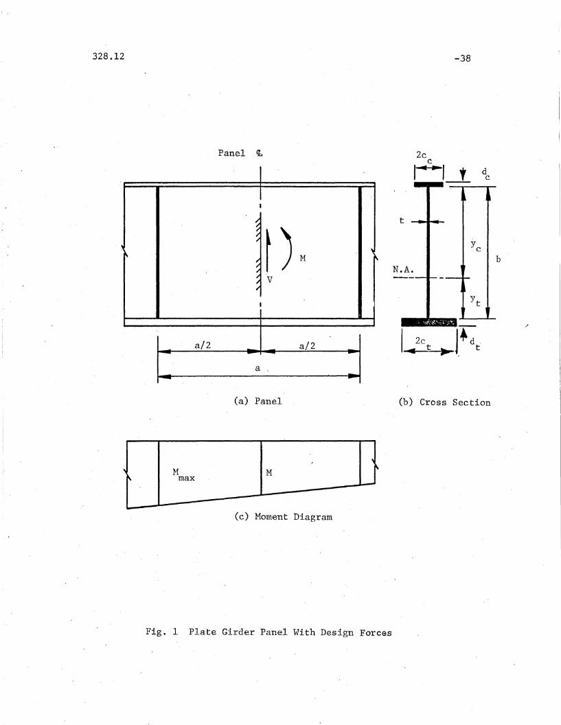
Design Conditions - A typical plate girder panel is shown in Fig. l(a).
The cross section is unsymmetrical and, for the sake of discussion, the
smaller top flange is assumed to be subjected to compression and the lar-
ger bottom flange to tension. "A larger portion of the web plate is thus
under compression. The internal forces acting in the panel are defined at
the mid-length as moment M and shear V. As indicated in the moment dia-
gram, Fig. ICc), a greater moment M is developed at one end of the panelmax
and it also is taken into consideration in design.

328.12
Since for a particular arrangement of loads on a plate
girder the moment in a panel is directly proportional to the
shear in it, it is convenient to define the moment in terms of the
shear span ratio ~.
-3
where
M ='~bV
M=--b V
(1)
(2)
Analogously to the theory presented in References 8, 9
and 10 three force conditions are considered here: pure bending
(V = 0), pure shear (M = 0, but M ~ 0), and a combination ofmax
shear and bending (M =f 0, V 1= 0). In the following, the strength
formulas for these cases are de"scribed separately and ,then their
application is illustrated with numerical examples.
Design of Stiffeners - This report does not deal with the design of
stiffeners since no additional studies on their strength were conducted
by the project. Current recommendations for proport~oning stiffeners
in panels designed for ultimate strength are considered to be adequate. (1,2)

328.12-4
2. ' 'BENDING' STRENGTH
It has been" found that the' ultimate capacity of a plate: girder
panel" subjected' to pure bending is limited by the strength of the
compression or tension flange rather than by the buckling of the web
plate, although the web plate after buckling does not contribute to the
strength of the panel as much as it would if it were flat.
The effective cross section of the plate girder panel after
web ~uckling can be visualized to have the compression flange column
composed of the flange itself and a portion of the web plate. A method
of analysis based on such an assumption is presented in Ref.9. Good
correlation was obtained with test results on symmetrical, unsymmetrical,
hybrid and homogeneous plate girders. Although the generality of this
method is very attractive, it was desirable to compare it with the
popular method developed by Basler and ThUr1imann (3) which has been
already accepted by AISC (2) and AASHO (1)
A series of sample computation showed that Basler's method agreed
quite well for symmetrical homogeneous girders and also that its familiar
and relatively simple formula could be modified to apply to unsymmetrical
'*and hybrid girders. Such a modified version of the Basler formula is
given here.
*The approximate_a.daptation to unsymmetrioal "girders made in Refs. 1and 21 is not suffioiently aocurate for the ~neral case, but rather,applicable only to plate girders of slenderness ratio less than approximately 200. The method for hybrid girders given in Ref. 20 is limitedto symmet'rical girders having the web which d.oes not bucl<:le beforeyielding.

328.12
. (3)is
-5
The original Basler formula established for symmetrical girders
M ~ I"cr ~: 1 - 0.0005 "~w ( ~ - 5".7 J- E )]u y.. cf Af t '!cf
(3)
where I is the moment of inertia of the cross section t A = bt is thew
areaarea of the web. Af = Afc =Aft is the flange~of a symmetrical girder, E is
the modulus of elasticity,''!cf is thes;i.tis~l s1=I'el:3f:l()~ the compression
flange_~_and y = y , band t are indicated in Fig. lb. A plausiblec .
extension of this· formula. to unsymmetrical sections can be made by assuming
that the effect of the buckled web may be evaluated as that for a syrnmet-
rica! section whose total depth is equal to the double of the web portion
under compression in the unsymmetrical section.
are then,to be'made in Eq. 3:
The following replacements
A = 2y tw cand bIt = 2y It
c(4)
Design of hybrid girders requires consideration of different
material properties of the web and flanges. Of particular interest is the
case when the web is of lower strength than the flanges. The following
formula which also incorporates a modification for unsymmetrical girders
is propo~ed here:
~ i\ Y. r-E I } ',.:O.ooz:.E....-.. (-.E.-2.85i!-)] + (1-~)(5)
Af t· (] I·C '. yvJ
in which
2.85 \(?) > 0Oyv{
and .(6)
Due to a lack of research information, set ~yw = (Jef when (Jyw > (Jef·
328.12
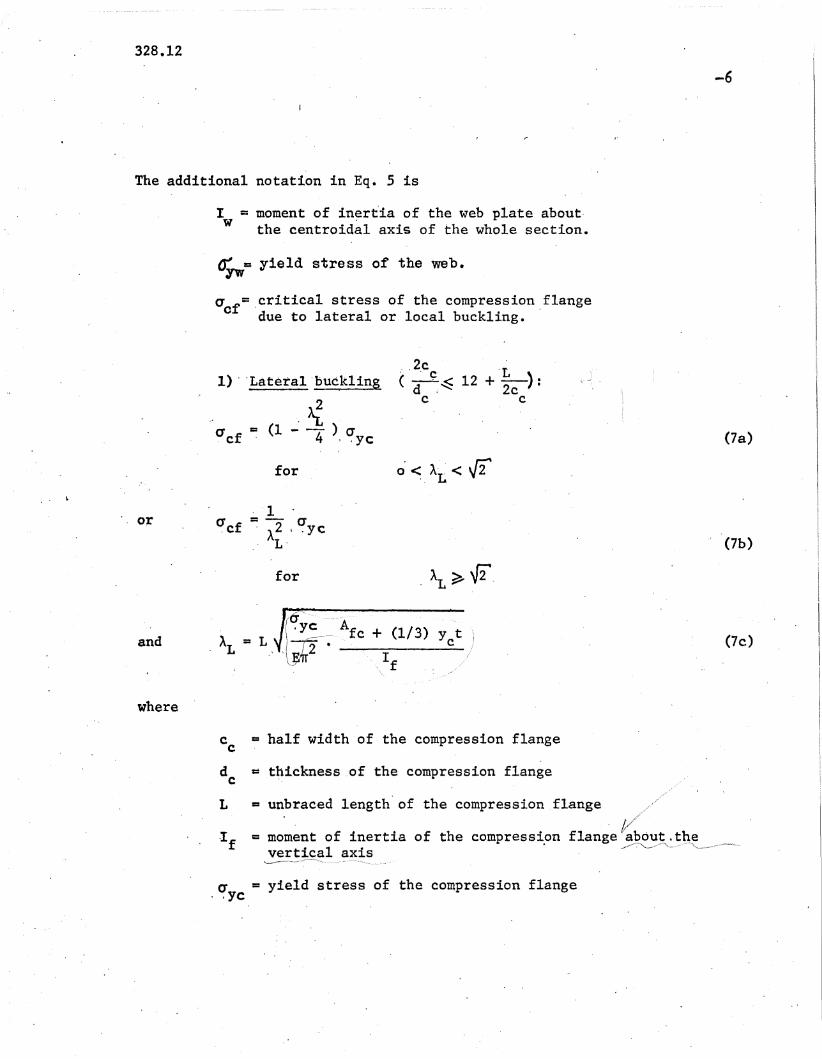
The additional notation in Eq. 5 is
I = moment of in~rt'ia of the web plate about·W the centroidal axis of the whole section.
~ = yield stress of the web.yw
acr= ,critical stress of the compression ,flangedue to lateral or local buckling.
--6
,,2e 'L1) , 'Lateral 'buckling (d ~. ~ 12 + 2c ):
.>i . c c
C!cf = (1 - 4 ) a (7a), .ye
for O'~AL< f2. '1
or~cf
=- ai\2 , .ycL·
J
(7b)
for .~~f2.
and (7c)
where
c = half width of the compression flangec
de =t~ickness .of the compression flange
L = unbra-ced length' of the compression flange j,""-
, t,,,,//i
.I f = moment of inertia of the compressi.on flange ....~~~'-~_~'1~~. __~vert~~al axis
a = yield stress of the compression flange.ye

328.12
2)
i '!cf
Loeal - (Torsional) -bticklin~ (2ee _> 12 +-.!!.-) :d _. ,'2c
c 'c
= [ 1 - 0.53 <. A - 0.45)1.36]'t '!yc.
or
for
. 'I(J =--cr
, · cf . A2 ' yc::t
for
(Sa)
(8b)
where20.425 7f E
(Bc)
According to Eq. 5 the plate girder strength is assumed to consist.
of two contributions. The first~ as given by the expression in brackets,
is the contribution of the web plate up to the point of yielding in the
web. This term is nothing else but the Basler formula (Eq. 3) with the
critical flange stress replaced by the web yield stress and modifications
made for unsymmetrical sections. Since the strength of the panel is
not(~_~hausted .:~t this point, the second term in parentheses reflects the
total moment contributed by the flanges.
Equation 5 is on one hand somewhat unconservative since its
composition assumes. that the neutral axis remains at its original position
in spite of redistribution of the web stresses due to buckling and
yielding. On the other hand it is conservative since it neglects the
contribution to the moment from the increases in web stresses, especially
in the tension zone. Since the equation gives very good correlation with

328.12-8
experimental results and a more rigorous approaCh~9) these two effects
apparently cancel each other.
For symmetrical ( b = 2Ye ) and homogeneous (CT = rr )'" . yw . ~ cf
girders Eq. 5 reduces to the original Eq. 3.
"Tension"Flange'Failure. When the tension portion of the web is
sufficiently larger than the compression portion, the bending capacity of
the panel may go up to the plastic moment M. Due to some uncertainties inp
the behavior of a very slender web, it is more conservatively assumed that
the~capacity is limited by the yielding of the tension flange.
"rM =-cr [1
u Yt ,· yt
Iw
I(9)
When it is uncertain whether the compression or the tension
flange failure controls the design, both, Eq. 5 and 9 should be
used to determine which one gives the smaller ultimate moment.

tributions:
328.12-9
3. SHEAR STRENGTH
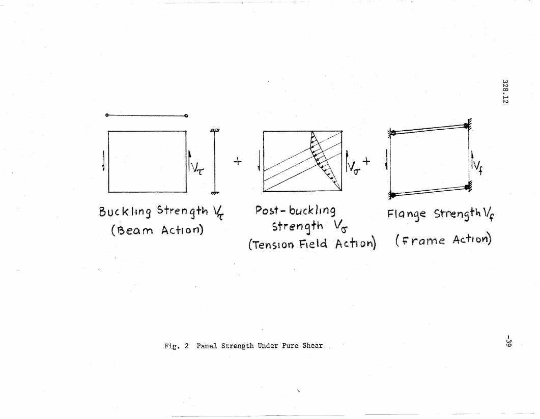
The ultimate strength of a plate girder panel subjected to
pure shear is assumed according to Ref.8 to consist of three con-
the buckling strength of the web V (beam action), therr
post-buckling strength of the web V (tension field action) which0"
leads to the formation of a tension diagonal in the web, and a con-
tribution resulting from the resistance of the flanges to the change
of the panel from a rectangular to a parallelogram shape V£ (frame
action).
These three ·strength contributions are shown in Fig. 2.
(10)
A parametrical study of the numerical output from a computer
program based on the method of Ref. 8 showed that the three individual
contributions could be computed with adequate. accuraoy from relatively
simple formulas suitable for manual computations.
Beam Action. - Beam action contribution V is the shear buckling strength of'T
the web and is given by the product of the web area and the shear
buckling stress:
(11 )

328.12
In order to conveniently define T in the elastic, iner
elastic, and strain-hardening ranges, the following non-dimensional
shear buokling parameter is introduced:
-10
where:
bA = 'I t
12 (I-v2) ~
J3 if E kv(12)
v = Poisson's- ratio
a = yield stress of the webyw
E = modulus of elasticity
k, = plate buckling coefficient in the elastic rangev
Assuming the web plate to be fixed at the flanges and pinned at the
stiffeners, k is computed as follows:v
kv
= 5.34 + 6.55 _ 13.71 + 14.10arfd O!
for a < 1.0
/i ~"l.-. I .
(13a. )
or kv
= 8.98 + 6.182
Q'
for a ::: 1.0
2.88--'- (13b)
With the shear yielding stress
(14)
the shear buckling stress T is given then as a function of Avon1ycr

328.12
for Av:::' 0.58(strain-hardening range)
[::'
'fer =[1 - 0.6150.. ,,- 0.58)1018J 'fy
~d~~"
for. 0.58 < Av ::: /2(inelastic range)
-11
,.cr (150)
for "A.,,> .[2(elastic range)
These are the same relationships as were used in the theory\8)They
are shown in Fig.3.
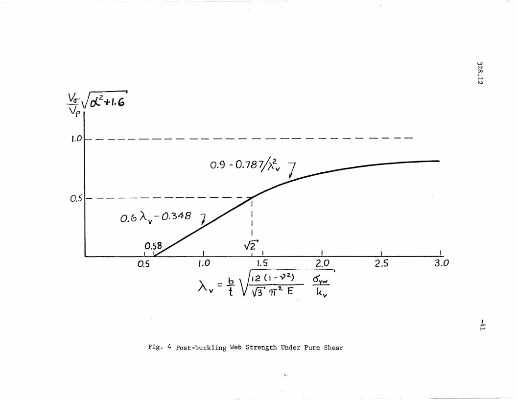
Tension Field Action. - The tension field stresses are assumed to
develop in the pattern shown by the middle sketch of Fig.2. The
inclined band has the maximum intensity which in combination with
the stresses at buckling may not exceed the yielding condition.
According to Ref.8" the tension field action contribution Vcr
is a· function of the aspect ratio Ct, web slenderness ratio (bIt), and
the material yield stress IT • Since the" method of Ref.8 requiresyw
the use of a digital computer, an analysis of the computer output
was performed for various combinations of geometry and material
properties. It was found possible to separate the effects of ~ and
Thus, V can be given as a function of(J

328.12
v = 0(J
for Av~ 0.58
-12
(16a)
where
Va
v(J
= 0.6 Av - 0.348 V
Vel + 1.6 P
for 0.58 < Av~J2
= 0.9 - O.787/Ae V~ if + 1.6 p
v = A ~ -::bt~p W {3 "J:>
(16b)
(160)
(17)
is the plastic shear force.
Frame Action. - The frame action contribution Vf
is the resistance of the
flanges to the distortion of the panel from a rectangle into a parallelo-
gram. The maximum frame action shear is assumed to be reached when the
mechanism shown by the right sketch of Fig. 2 is formed. Because the con-
) tinuity of the web provides sufficient rigidity to, essentially, preclude
rotation of the transverse stiffeners, plastic hinges are assumed to form
in the flanges.
According to the method of Ref. 8 a portion of the web plate
is assumed to act with the flanges. For the sake of simplification,
the contribution by the web plate is neglected here. Since the frame

328.12
action contribution to the ultimate panel strength is, in most cases,
about 10%, this assumption does not introduce any appreciable error in
the final result. Thus, Vf is given by
-13
(18a)
where me and rot are the plastic moments of the compression and tension
flanges, respectively. For flanges consisting of rectangular plates,
this equation can be rewritten by
V 1 (0' A d + a Ad)f = 2a yc fc c yt ft t
(18b)
where Gyc ' Afc ' dc and Gyt ' Aft' dt are, respectively, the yield stress,
the area, and the thickness of the compression flange and the tension
flange.
Design Formulas. - Substitution of the three contributions into Eq.l0
from Eqs. 11, 16 ~d 18 gives the following design formulas
for the ultimate shear strength. It is assumed that the yield stress
of both flanges is the same, Gyc = Gyt = GyfO
(199.)
for Av:: 0.58(strain-hardening range)

328.12 f
fI; -14
or V = vpfl[l_ 0.615 (A v- 0.58)~18J + 0.6 Av - 0.348
u ~ ~ cl' + 1.6 I
for 0.58 < Av <J:2(inelastic range)
(19b)
{1 0.9 - O.787/A~
or V = V - +u P A~ +
(190)
for Av>.J2(elastic range)
For steel with v = 0.3 and E = 29,000 ksi, Eq. 12 gives
a is in ksi and k is obtained from Eq. 13.yw v
(20)
Comparison with Test Results and Other Methods. - Aoomparison of the
proposed formulas, Bas1er's~4) and Fujii's (13) methods with the available
test results are shown by the cumulative distribution curves in,
Fig.5". It is seen that the correlation of the proposed formu~as
with the test results is within 10%. Basler's method gives less than
10% deviation for about 65% of the tests' and larger deviations (up
to 33%) for about 35% of the tests. Since Fujii's method does not
apply to unsymmetrical p~ate girders, two sets of computations

328.12
were made. The thin dashed line denoted by "s" in the figure re-
-15~
presents the Fujii's case when both flanges were assumed to be of
the smaller flange size, and the thin solid line denoted by "L" re-
presents the case of assuming both flanges as the larger flange. It
is seen that Fujii's method gives good correlation with tests for
symmetrical girders, but the method is ambiguou~ when applied to un-
symmetrical girders.
End Panel. - Full development of the tension field oapaoity requires
that the neighboring panels be sufficiently strong to anchor it.
This me8~ns that either tlle panel at the encl of a girc1er Sllould have
a very strong end stiffener capable of resisting tlle horizontal
OOnl})Onellt of the tension field. force, or that the panel should be
designed to develop only the bucklirl.go strength. The latter approach
is recommendE}d here. Thus, the shear ca.paoity of the end panel is
to be oomputed from Eq.lO with V~ = o.
The res'ul tant shear capacity of the e11cl panel is grea.ter
than that specified by AASHO(l) and AISC(2)because of two reasons:
1) the \veb plate is assumed to be fixed at the flanges and simply
supported at the stiffeners ra.ther than simply supported at all
edges, and 2) the frame action shear Vf is included.

328.12
4. STRENGTH UNDER BENDING AND SHEAR
-16
The strength of a plate girder panel under various combinations
of shear and moment can be described by the interaction curve 0 ~Q -Q ~Q -Qa"'5 4 1 2
shown in Fig.6. The ordinate gives the shear non-dimensionalized with
respect to the ultimate value for the pure shear case, and the abscissa
is the moment non-dimensionalized with respect to the ultimate moment
for pure bending. The right and left parts are,'respectively, for the
larger portion of the web plate under compression and tension as indicated
by the small sketches under the diagram.
Depending on the relative magnitude of shear and moment and
on the direction of the moment, the ultimate strength of the panel may
be controlled by one of the following three conditions: 1 the shear
~~h=·~J:.e,Q,g£,~"st,,,~,Q,Yc,=,,§n:stt!fg)(web failure---portion Q4 -Ql -Qa ), 2) !Jl~,
~~~"""fl~E~pg"~ll reduced by shea!." ~.~~ liUl~~_:"~.~! t~=J::omI>~~~~f~~~!a.~~e
~~](portion Qa ..Q3)' and 3 )~~~~P~!n&f'l~E~!1.g!!t:t"~~~~~~_-!>Y~.~lle_Cl.~
and limi~~d_~ythe lding of the tension flange (portion QS-Q4) 0 The
mechanisms of failure are indicated by the insert sketches. The in~
dividual contributions due to beam, tension field and frame actions are
shown schematically by separate areas in the interaction diagram o The
design procedure recommended here is to compute the ultimate strength
for each applicable strength condition and use the lower value as the
controlling one.
Web Failure. (Curve Q4 -~ -Qa in Fig. 6 ) - As the insert in Fig. 6 shows,
the panel strength is obtained as a sum of buckling (beam action), post-
buckling (tension field action), and flange flexural (frame act~on)
contributions.

328.12
This is analogous to the case of pure shear, except that now each con-
tribution is affected by the presence of bending moment.
-17
vue VTC + VCJC + Vfc (21 )
where subscript c indicates the combination of shear and bending forces.
The beam action contribution is
v =,. AT'C c W
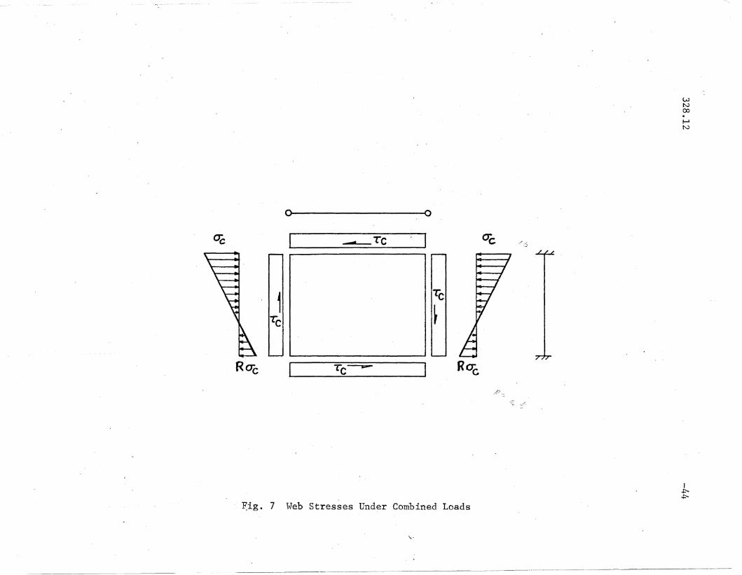
T is the shear buckling stress of the web subjected to shear andc
bending stresses as shown in Fig.7. It may be computed with adequate
accuracy from the following interaction equation
where
R = ratio of the maximum tensile stress (or minimum com-
pressive stress) to the maximum compressive stress
(see Fig.7.' ). R is negative when the stress is tensile.

328.12
The buckling stress under pure bending, IT ,is to he computed fromcr
-18
the following equations which are analogous to Eqs.15
CJ' = (Jcr yw
for Ab ::: 0.58
(yielding)
for 0.58 < Ab :::. Vi'(inelastic range)
or
used for T :cr
(24a)
(24b)
where
(Jcr
1= -- cr
A 2 ywb
for Ab > V2 \'\;(elastic range)
(240)
~, the plate buckling coefficient is conservatively obtained by as
suming a = 00 and deriving the following formula by curve fitting
~ = 13.54 - 15.64 R + 13.32 R2 + 3.38 R3 (26)
for (-1.5) ~R~ (0.5)
Since G is directly related to T byc c
\,-'
)
328.12
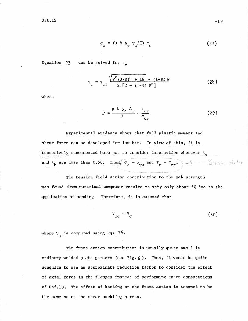
crc (l-L bAy II) Twee
-19
(27 )
Equation 23 can be solved for Tc
where
Tc= or ; ( _n 2 + 16 - (l+R) F
cr 2 .. [2 + (l-R) F3 ](28)
F~ b Y A T___c_w_ • -E.
I crcr
Experimental evidence shows that full plastic moment and
shear force can be developed for low bit. In view of this, it is
tentativ~ly~,reconnnended here not to consider interaction whenever AV
and Ab
are les s than 0.58. Thenr--cr = er and 1" = rr •(' . c yw c' cr
The tension field action contribution to the web strength
was found from numerical computer results to yaty only abo~t 2% due to the
application of bending. Therefore, it is assumed that
v = Vcrc cr
where V is computed using Eqs.16.cr
The frame action contribution is usually quite small in
ordinary welded plate girders (see Fig. 6). Thus, it would be quite
(30)
adequate to use an approximate reduction factor to consider the effect
of axial force in the flanges instead of performing exact computations
of Ref .. lO. The effect of bending on the frame action is assumed to be
the same as on the shear buckling stress.
328.12
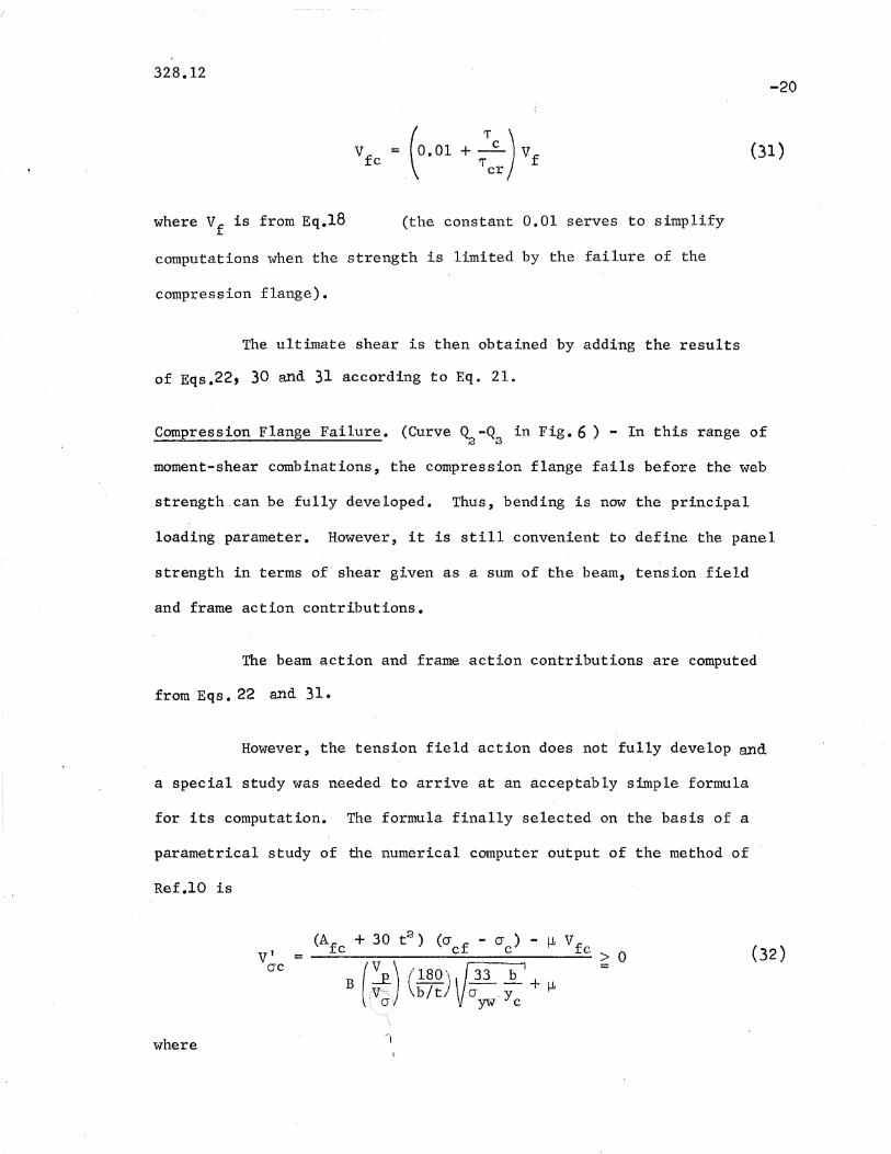
v = (0. 01 + ~) Vfc T. fcr
-20
(31)
where Vf is from Eq.18 (the constant 0.01 serves to simplify
computations when the strength is limited by the failure of the
compression flange).
The ultimate shear is then obtained by adding the results
of Eqs.22, 30 and 31 according to Eq. 21.
Compression Flange Failure. (Curve Q -Q in Fig. 6 ) ... In this range of2 3
moment-shear combinations, the compression flange fails before the web
strength ,can be fully developed. Thus, bending is now the principal
loading parameter. However, it is still convenient to define the panel
strength in terms of shear given as a sum of the beam, tension field
and frame action contributions.
The beam action and frame action contributions are computed
from Eqs. 22 and 31.
However, the tension field action does not fully develop and
a special study was needed to arrive at an acceptably simple formula
for its computation. The formu~a finally selected on the basis of a
parametrical study of the numerical computer output of the method of
Ref .10 is
where
v' =crc
(Af + 30 t2
) (cr f - cr ) - ~ Vfc c c c > 0
3 (,~) (~~~) V;~ :C'I + ~

328.12
B = O.338A - 0.196v
-21
(33a)
or
for A > V2v
(33b)
A is given by Eq.12v
and a is in ksi.yw
Besides the composition of Eq.32, the parameter which
was developed from the numerical output is B g Figure 8 shows a plot
of B versus A. The points give the values of B obtained by equatingv
the ultimate strength expressed by the design formula to the theore~
tioal ultimate strength at the p~,int of transition from web failure
to compression flange failure; ea~1:lPQintrepJ'esentsa l'Clrti<:t1lal:'l'c9.IleJ.'!,-------'---- "'-
A ~~~~~;~~~~~/:f'ii)thrOUgh the plotted points was used to find the
expression for B when A > Vi, Eq.33b. Since for 0.58 < Av:::' Vi ,v
V· represents only a small portion of the total shear strength,ere
7 the ~_f_~ec~ Qf,_B- would,_b__e __ne_gligj~p __!~_~__ Thus, a straight-line approxi-
mation is made, Eq.33a.
The ultimate panel shear causing failure of the compression
flange is given by the sum of the values from Eqs. 22, 31 and 32.

328.12-22
and the corresponding panel moment is
Mue =Mb VI· uc
~Mu (35 )
Equation 35 indicates that M should not exceed Muc ·u Since the nature
of the approximations involved in the evaluation of VI could lead to an(J'C
unrealistic condition of Muc ' computed from Eqs. 34 and 35, being less
than Mu for the case of pure bending, the constant 0.01 was introduced
into Eq. 31 to preclude this situation. The result is illustrated in the
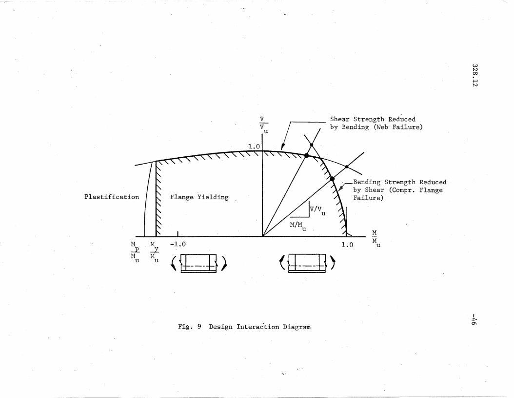
right lower corner of the interaction diagram of Fig. 9.
Ultimate strength Under Bending and Shear. - Since the specifio combi
nations of moment and shear which are controlling for the web or oompre-
esion flange failure modes are not defined, it is neoessary to check
both modes and seleot the one which gives a lower oapacity.
A typical interaction diagram based on the above derived
formulas is shown in Fig. 9. A ray emanating from the origin repre-
sents an inoreasing load for a partioular moment-shear combination.
Two interseotion points with the interaotion curves are shown, one due
to web failure and the other due to the compression flange failure.
The smaller shear is to be selected as the controlling ultimate shear.
For the two rays shown, the controlling cases are indicated with the
heavy dots.

328.12-23
Maximum Panel Moment. - Since in a panel under combined ,forces the
moment at one end of the panel is greater than the mid-panel moment
used in the analysis (Fig. 1), it may happen that the strength will
be controlled by this maximum panel moment M • This is particularlymax
true for panels with large aspect ratios.
A reasonable and sufficiently accurate approach appears to
be a requirement that the maximum panel moment be below the moment
Muv· =
u 'b (~ + ~ 0') "
\vhere M is the smaller value of Eq.5u or Eq.9.*
Tension Flange Yielding. - As indicated by the vertical line marked
"Flange Yielding" in Fig. 9 , t!!_~ ~h~Q~_1?Y __ Eq 32a.lao-co1lers__ :t_he~_c-a-a.Et-~
fl~g~. This oriterion may be somewhat conservative for sections with
low bit (compact seotions) or in cases when most of the web is inrI'
tension and essentially full plastio moment may be attained (see the
left-most curves in Figs. 6 and 9). It is left to the judgement of
the designer when he \"{ould want to take advantage of the addi ti'onal
panel c~paoity due to plastification.
"kA more refined check on the compression flang~ capacity is (withfrom Eq.5)
MV. = u
u b (~ + ~ a)
Mu

328.12
5· CO:NSIDERATION OF FATIGUE
-24
Many tests as well as a oomprehensive study oonducted speci
fically for this purpose(19) showed that initial out-of-plane deflec-
tiona of the web plate have no detrimental effect on the ultimate
strength of girders Bubjected to statio loads. However, when the load
applioation is repeated many times as is the case for bridge and orane
girders, fatigue cracks may develop in the web due to the lateral
flexing ("breathing") of the web at eaoh load application. Initial
deflections and the amo~pt of stressing beyond the buckling stress
level of the web plate appear to be tile principal factors influencing
the development of these fatigue cracks.(16) Since both of these
factors are functions of the web slenderness ratio bit, a recommendation
, was made to limit the web slenderness ratio to a specific value.(l, 21)
This bit limitation was crit:tcally reviewed in Reference 15
in the light of additional tests on unsymmetrical plate girders. It
waS found to be somewhat oonservative for oonventionally proportioned
girde~s but is endorsed here until more research is conO.uoted.
/
2 Yo 1,150 b~ ~t \I rJirw' t
where o;w is in ksi.
(38 )

328.12 -25
It should be noted, however, that Eq. 38 may be unconservative
for girder panels with stiffeners of high torsional rigidity, such as
heavy bearing stiffeners and stiffeners with closed sections. Until more
research is conducted, it is tentatively recommended here that the web
panels adjoining such torsionally rigid stiffeners, be checked not to
buckle under a load equal to abowt 1.1 of the working load.
/

328.12
-26
6. GIRDERS WITHOl~ INTEm}~DIATE STIFFENERS
Plate girders having stiffeners only at the sup~orts (bearing
stiffeners) an<1 possibly under l1eavy concentrated loads are of considerable
economic interest. As described in Referenoes 8 Ana. 10, 8ll0h 'Plate
girders may be safely al1d aCcllrately designed by neglecting the
contribution of the tension field action (post-buclcling strength) \l\Thenever
the panel aspect ratio cf..... exceeds 3.0. 'rhus,
v = Vrr- + Vflie t: C 0
where V~c and Vfo are given by Eqs. 22 and 31, res~ectively, or by
Eqa. 11 and 18 for the ca.se wIlen M= O. It is important that su.ch
long parlels be a.lvv-ays checlced for the maximum panel momer:t according
to Eq. 36.
Plate girders without intermediate stiffeners and subjected
to uniformly distributed static loading, such as roof girders, have
attracted attention of engineers in Swed_en. (7) A temporary design
specification was developed ~rimarily on the basis of experimental
work. A com~arison of Eq. 39 with this specifioation,for a few samr)le
girders showed that for most cases Eq. 39 was more conservative than
the specification rl11es.

328.12 -27
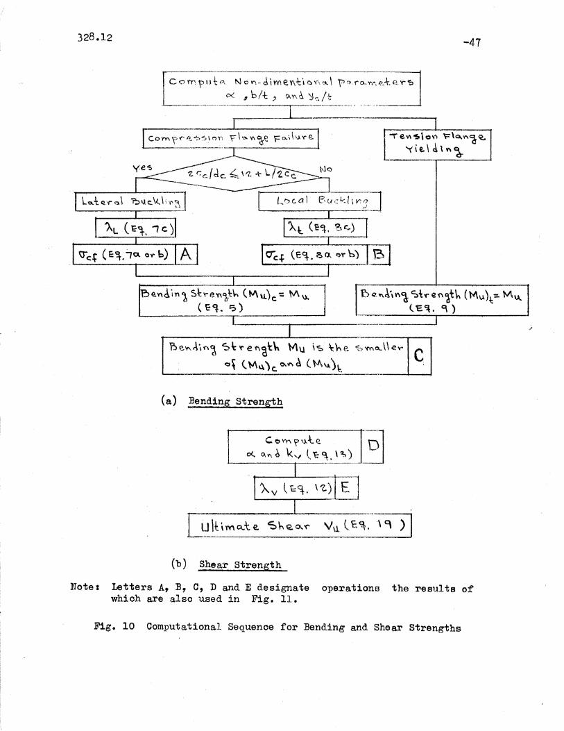
7. DESIGN PROCEDURE'AND'NUMERICAL'EXAMPLE
The sequences for the computation of the ultimate strength of
a panel subjected to pure bend~ng~ pure shear or a combination of bending
and shear are shown schematically by block diagrams in Figs. lOa, lOb
and 11, respectively. The following numerical example illustrates the
procedure in detail.
Example
Given is a bridge girder panel with the following dimensions
(in inches) and material properties:/
Panel length
Panel depth
Compression flange:
Tension flange
Web
a = 126.0
b = 84.0
2c x d = 27.0 x 2.5c c
2ct
x dt
= 27.0 x 1.75
b x t = 84 x 7/16
Unbraced length of the compression flange:
Yield stress of the compression flange
tension flange
web
L = 126.0
cryc = 100.0 ksi
a = 100.0 ksiyt
Uyw = 36.0 ksi
Cross-sectional properties: I = 229,000.0 in.4,Iw = 22,750.0 in.
4, If =
4,100 i~,AfC = 67.5 in.2
, Aft = 47.2 in.2
, Aw = 36.75 in.2
, Yc = 36.4 in.,
Yt
= 47.6 in.
Non-dimensional parameters:
R =- (y Iy ) =- 1.28t c
a, = alb = 1.5, bIt = 192, 2y/t =c

328.12
Find:
The ultimate panel str~ngth for:
(a) Pure bend~ng
(b) Pure shear
(c) Combination of bending and shear with ~ = M/bV = 14.0
-28
Check fatigue requirement:1,150
Eq. 38: ---=~.yw
1,150
1"36= 192 = b/t
> 2y,/t, therefore, O.K.c
(a) rB~nding Strength
Check: 2 c /d = 27.0/2.5 = 10.8c c
12 + L/(2c ) = 12 + 126.0/27 = 16.7 > 10.8. c
Thus, lateral buckling of the compression flange governs
/
Eq. 7c:
Eq. 7a:
Check:
Check:
Eq.5 :
A = 126 100 2. (67.5 + (1/3)(36.4)(7/16» = 0.314< {2L 29)00011 4,100
O"cf:;: 100(1 - 0.3142/4) = 97.5 ksi
r:::r = 36.0 ksi <cr f = 97.5 ksi. Thus, use C) = 36.0 ksiyw c 'YW.
y/t 2.85~E/cr~:;: (166/2) - 2.85 ~. (29,000/36)' :;: 2.0> 0
(M) = 229,000 (97.5»)~ _ 22,750 + 36 [22,750u c 36.4 l 229,000 ~7.5 229,000
- 0.002 (36.4(7/16) )(2)]} = 575,000 kip-in.67.5
O.K.
Eq. 9: ( ) = 229,000 (100)[1 _ 22,750Mu t 47.6 229,000 (1 ~ ~)] = 450,000 kip-in.100
(MU)t <: (Mu)c ' thus, yielding of the tension flange governs:
M = 450,000 kip-in.U i
328.12
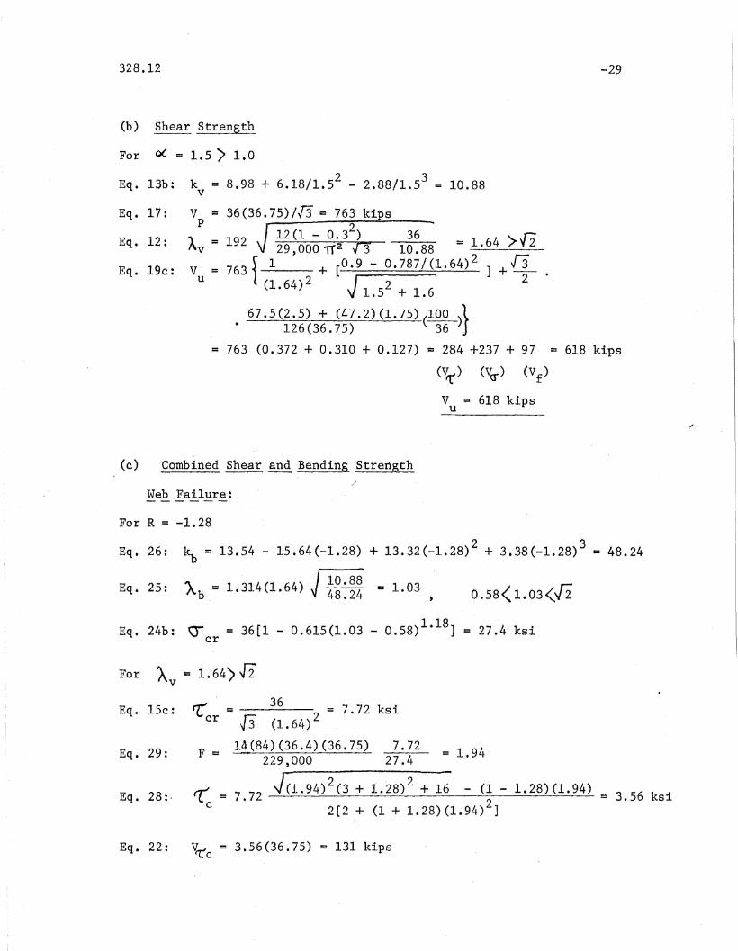
(b) $hear Strength
-29
For 0( = 1.5 > 1.0
Eq. 13b: k = 8.98 + 6.18/1.52 - 2.88/1.53= 10.88v
Eq. 17: V = 36(36.75)/[3 = 763 kips
p J12(1 - 0.32) 36 - >.17Eq. 12: Av = 192 29,000 11'2 T3 10.88 = ~.64 v2
Eq.19c: V = 763 S 1 . + [0.9 - 0.787/(1.64) ] +.[3u l 2 J 2 ·
(1.64) 1.52 + 1.6
67.5(2.5) + (47.2)(1.75)(100 )}· 126(36.75) 36
= 763 (0.372 + 0.310 + 0.127) = 284 +237 + 97 = 618 kips
(Vrr) (VG'") (Vf)
V = 618 kipsu
(c) Combined Shear and Bending Strength
Web Failure:
For R = -1.28
Eq. 26: ~ = 13.54 - 15.64(-1.28) + 13.32(-1.28)2 + 3.38(-1.28)3 = 48.24
IlO:88Eq. 25: Ab = 1.314(1.64) ~ 48j4 = 1.03 , 0.58< 1.03<[2
Eq. 24b: cr = 36[1 - 0.615(1.03 - 0.58)1.18] = 27.4 ksicr
For A = 1.64) J2v
Eq. 15c:
Eq. 29:
Eq. 28:·
rr = 36 2 = 7. 72 ksicr [3 (1.64)
F = 14(84)(36.4)(36.75) 7.72 = 1.94229,000 27.4
r 2 . 2~ = 7.72 ~(1.94) (3 + 1.28) + 16 - (1 - 1.28)(1.94) = 3.56 ksi
c 2[2 + (1 + 1.28)(1.94)2]
Eq. 22: V~c = 3.56(36.75) = 131 kips

328.12
Eq. 30:
Eq. 31:
Eq. 21:
Vo- c ;:: Vcr = 237 kips
Vfc = 97(0.01 + ~:~~) = 45.6 kips
(V ) = 131 + 237 + 45.6 ;:: 413.6 kipsuc w
(v ) ~ 413.6 kipsuc w
-30
Eq. 32:
For '" ;:: 1.64 >f2.v
Eq. 33b: B = 0.235(1.64) - 0.05 = 0.335
Eq. 27: ~ = 3.56(1.94)(27.4/7.72) = 24.4 ksic
[67.5 + 30(7/16)2](97.5 - 24.4) -14(45.6)v' =~---~~.....---=--------.-;..-..,.;....-~:...-----=--O-c
0.335(;~~)(i~~) ~~~~~~4) + 14
Eq. 34: (V ) = 131 +305 + 45.6 = 481.6 kipsuc c -
(V ) =481.6 kipsuc c
= 305 kips
v = 413.6 kipslie
Eq. 35: M = 14(84)(413.6) = 486,000 kip-in.ucM = 486,000 kip-in.ue
Check Maximum Panel Moment
s~
Eq. ~ (or from(a»:
Eq. 9 (or from(a»:
(M ) = 575,000 kip-in.u c
Since (M) ) (M )t' useu c u
Eq. 36: The ultimate shear
(Mu)t
,_ 450,000Vu - 84(14 +(1/2)1.5) = 363 kips

32 .12 -31
v~ <. Vuc ,(363 <. 413.6) t the ultimate capacity of the panel
un~er combined loads (~= 14) is
.;f,
v = V' = 363 kipsuc u
and (Eq~ 35): Muc 14(84)(363)
M = 427 t OOOkip-in.uc
427,000 kip-in.
(d) Summary of Results
·i(a)~Pure Bending: -------------------------- M = 450,000 kip-in.u
(b ): Pure Shear: ---------------------------- V = 618 kipsu /
(c) Combined Bending and Shear (r= ~v = 14): v = 363 kipsuc
M = 427,000 kip-in.ue

328.12
8. ACKNOWLEDGE1illNTS
-32
This report was prepared as part of a research project on
unsymmetrical plate girders conducted in the Department of Civil Engi-
neering, Fritz Engineering Laboratory, Lehigh University, Bethlehem,
Pennsylvania. Dr. David A. VanHorn is Chairman of the Department and
Dr. Lynn S. Beedle is Director of the Laboratory.
The authors express their. gratitude to the American Iron and
Steel Institute, the Pennsylvania Department of Transportation, the
Federal Highway Administration of the U. S. Department of Transportation,
and the Welding Research Council for supporting this project. They also
gratefully acknowledge the technical guidance provided by the Welded Plate
Girder Subcommittee of the Welding Research Council under the consecutive
. ,chairmanship of Messrs. M. Deuterman, E. G. Paul~t, and G. F. Fox and by
the Task Group on Unsymmetrical Plate Girders under the chairmanship of
Mr. C. A. Zwissler and, lately, of Mr. L. H. Daniels •.
The tletailed reviews of this report and suggestions made by
Messrs. H. G. Juhl, J. Nishanian and J. ,L. Durkee are sincerely appreciated.
/

328.12 -33
9. APPE1IDIX I. - REFERENCES
1. Amerioan Association of State HighwaY Officials, Interim Specifications for Highw~y Bridges, 1970-71, AASHO, Washington, 1971.
2. .ltmerioan Institute' of Steel Construotion, Specification for theDesign, Fabrication and Erection of Structural Steel for ---Buildings, AlSO, New York, 1963. ---
3. Basler, K., and ThtlJ:'limann, B., "strength of Plate Girders in Bend.ingtt ,
Proceedings ASCE, Vol. 87, ST7, August 1961.
4. Basler, K., ttstrengtll of Pla.te (jirders in Shear, tt Proceedin~
ASeE, Vol. 87, ST7, October 1961.
5. Basler, K., ttstrengtll of Plate Giro.ere under Combined Bending and.Shear~" Proceedings ASCE, Vol. 87, ST7, October 1961.
6. Basler, K., Yen, B.T., },'Ttleller, J .A., and. T11urlimann, B., ftiVeb Buckling/
'Tests on Vleld.ed Plate Girders, It 'Nelding He search Council BulletinNo. 64, New York, 3e~tember 1960.
7,. Bergfelt, A., aJ.1d. ITovilc, J., "Thin-walled ,DeelJ Plate Girders UnderStatic Loads", Fi11al H.eI)Ort of tlle Eighth Congress of the International Jissociation for Bridge and structural Eneineering, heldill lJevl Yorlc, Septenlber 1968, Etl'H, Zurich.
8. Chern, C., ancl Ostapenlco, A., ttT.Jltimate strength of Plate GirderslJnd.er Sllear", Fritz :U;ngineering' Laborator;)r Rel!ort IJo. 328.7,Lehigh tJniversi ty, A.Uf~:ust 1969.
9. Chern, C., ana. osta:penko, /'i.• , "Be11ding streng;th of UnsyrnrnetricalPlate Circlers" , Fritz EnrJineeri11g IJo.boratory Report l~o. 328 .e),Lelligh TJniversi ty, September 1910.
10. Chern, C., 8.XlclOstapenlco, A., UUnsymmetrical Plate Girders tmderShear anc_ ?Eoment tt , Fritz 'Engineering Laboratory ·Re-port 1'To.328.9,I 1ehigh tJniversity·, October 1970.
11. Dimitri, J.R.,~,nd Ostapenko, A., "Pilot Tests on the Static strengthof Unsymmetrical J?late Girders tt , Vrelding Research CouncilB}llletin rJo".156, l'1"eVil York, l\Tovember 1970.
12. Djubek, J., ttThe Design Theory of Slender V{ebplate Bars tl,
Stavebniclc~ Casouis, Sav XV, 8, Bratislava, 1967.

-34328.12
13. Fujii, T., uOn an IJu-p'roved Theory for Dr. 3asler's TheorY,1t FinalReport of the Eighth Congress of the International ARsociationfor Erj,dge and r3tructural I~ng'ineeril1.g, helrl in l\fevt/ York,September 1968, ]~rrH, Zurich. '
14. Ostapenl;:o, 1\. anel Chern, C., "strength of r/ongit·udinally StiffenedPlate Gil)ders under Conlbined Loads tI , Fritz ~;ng~ineering Laborator:~t
RelJOrt 1\'0.328.10, Lehigh lTniversi ty, December 1970.
15- ,Parsane jacl, ~5., ancl OstaT,enko, Jt., "On tIle Fatigue strengtll of tTnsymmetrical Bteel r'late Girclers," Vlelc1.ing Research COllncilBulletin No. 156, rew York, November 1970.
16. P~tterson, P.J., Corradr:, S ....A.., IIuang, J.S.,nnd Yen, B.T., "Fatig'tlenncl Static Tests of tr,vo \Helded Plate Girders,tt VJelding ResearchCOl..lncil Bulletin 11·0.155, l\Tevr Yor}:, OctolJer 1970.
17 • Rockey, K. C., and Skaloud, I~E., "Inflllence of Flange st iffness uporl.the Load. Capaci ty of 1t~{ebs in Shear, tI Final Report of the EighthCongress of the InterrlHtional f~8f;',ocia.tion for Bridge ancl StructllralEng'ineeri!l£;; I'elc1 in J?evl York, September 19hel, Err'}I, Zurioh.
18. Schueller, Vi., and. Osta-perlko, A., ttTests on a Transversely and on a /Longitudinally stiffened TJnsymmetricA,l I"late Gir('ler", \VeldintS:
Researc11 CotUlcil ;Bulletin 'No .156, l~e\~T York, November 1970•.
19. Shelestenko, L.P." Dushnitsky, V,}/i. and Borovikov, 'J., "Investigationof- the I~nfll1ence of Initial 11~!eb -Defor!nations on the tTl timt1.testrGng~th of \VelcJ.ed })late Girders u , Rese,':],rch ~ St'eel ~ Comnosi.te
,s.u!)erstrtlctures £! Bridges, No.76, rrr:J~nsport, JV[oscow, 1970. (In Rl1sf~ian)
20. Subcommi.ttee 1 (IIybrid Benms and Girders) of the Joint ,!iSCE-At\SITOCommitte8 on Flexural J,,'jembers, ttDesign of EjTbrid Steel Beams",I.r0ceecling~, ASC~, '~Tol.~:.','4, ST6, J11ne 1968.
21. Vincent, G.S., ttrJ:entative Criteria for !,o,g,d Fq,ctor l)esign of SteelIfigl1vlay Dr:i.dges tt, Alnerican Jr011 a..D'el f:;tee 1 Il:stitute Bltlletiny'o.lS, :r,~arch 1969.

328.12 -35
10. APPENDIX II. - NOTATION
Area of the compression flange.
Area of the tension flange.
Area of the web.
B
E
Parameter defined by Eq. 33.
Modulus of elasticity (Young's modulus).
F Factor defined by Eq. 29.
I hiloDlent of inertia of the girder cross section.
Moment of inertia of the compression flange about the verticalaxis.
./
I w Moment nf inertia of the web about the centroidal axis ofthe whole cross section.
tJnbrftced lengt4 of the oompression flange.
Design moment at mid-panel.
Maximum moment in the panel.
Plastic moment of the panel.
Ultima,te moment of the panel under pure bending.
Ul t:imate moment of the panel under combined forces.
L
Muc
M Moment ca~sing yielding of the tension flange.y
R Ratio of the maximum tensile stress (or minimum oompressivestress) to the maximum compressive stress of,the web (negativewhen the stress is tensile).
Mp
l~u
Mmax
V Design shear at mid-panel.
Vf
FraJIle action shear und.er pure shear.
Vfo Frame action shear uncler combined for'ces.
V Plastic shear of the web.p

328.12 -36
v~ Tension field action shear under pure shear.
v~c Tension field action shear under combined forces.
V~o Inoomplete tension field aotion shear under oombined forces.
V~ Beam action shear under pure shear.
V1c Beam action shear under combined forces.
Vu Ul timate shear strength of the pane1 tmder pure;' shear.
V' Ultimate shear oontrolled by the maximum panel moment.u
V Ultimate shear strength of the panel under combined forces.uo
a Panel length.
b Panel depth.
co Half width of the com!)ression flange.
Half widt'h of the tension flangte.
Thiokness of the oompression flange.
Thickness of the tension flange.
Plate buckling ooefficient for pure shear (Eq_ 13a and 13b).
Plate buckling coefficient for pure bending (Eq. 26).
Vleb thicl{ness.
"
Distance from the oentroidal axis to the compression edge of the we?- .__'- -.,.-
Distanoe from the centroidal axis to the tension edge of the web.
Aspect ratio.
Web buckling parameter for bending, Eq. 25.
Web buckling parameter for shear, Eq. 12.
Lateral buokling parameter, Eq.7c.
Local (tor;si'onal) buckling parameter, Eq. 80.
Shear span ratio.
Poisson's ratio.

328.12-37
Bending buokling stress at the extreme compression fiber ofthe web.
Buckling stress of the oompression flange.
Web buckling stress under pure bending.
Yield stress of the compression flange.
Yield stress of the tension flange.
Yield stress of the web.
Shear buckling stress under oombined forces.
Shear buckling stress under pure she~r.
Shear yielding stress.
328.12 -38
I 2c J~._... t_,...~ t
N.A.
dc
"
b
2cc
I~I ,-----..'---t
Panel <t
I
~
)~
t", ,
~.~ M ~
;i
~ V~
II
a/2 - - a/2 -~ - - -
a " -~ -
(a) Panel (b) Cross Section
M.max M
(c) Moment Diagram
Fig. 1 PIate Girder Panel With Des igll Forces
o a
w~
00.f-ltv
J tv'[' + j ,/.//
-///
~ I tVa- +'....... .
Buc k Itn9 5t¥enqth ~
(eeo rn Ac. +1 0 n)
Po~t - buck1t t1gstren~+n· Vcr
(TenSion Fie1clAch on)
i=lQ n~e Stren5t~ 'If
( ~ fame Ac.tlon)
Fig. 2 Panel Strength Under Pure Shear '.
....
IW\..0

Wtv(Xl.r...aN
3.02.52.01.5
:cr=I-O.615(A;O.58)1.I8y
~
1.0
'T:• T~ =1+4.3(0.58-A~·56 .
\~~
-\~.(").
\~%~
SCtC.fF - i'lJ.g 0 1\
v"ve
0.5
II II 1- - - --,--- ----
. I II I·1
S · I I . I EI ·train _I ~ · I - astlcHardening i,ne,ast'i BUCkltngTBuckling
0.58 1 -\{2o
f .5
J.0
0.5
T"crTy
A ~.k\ 112 (I_";z) . G(wv t V'13 rrr1. E k'l
I~o
Fig. 3 Buckling Strength of the Web Under-Pure Shear..... -
- .
l.J,JN(».J-lN
1.0 -- -- - - -- -- -- -- -- -- -- -- -- -- --- ---- -- -- -- -- -- -- - ---
. 7/..2.0.9 - O.787;Xv
3.02.5O.S 1.0 1.5 2.0I '
b \ /.'2 (I-V~) 60 w
Av =T V-\13 1;'- E ~
0,51- ----- - --- - - --
O.6Av-O.348 1/:J
V21
I~
f--I
Fig. 4 Post-buckling Web Strength Under Pure Shear
\,-

I.p-.N
Wtv(X).~N
100
f
••
- .. -.-'
p:, OF
..........
I r WE I·;: J -........o SO 65 _75 90
" (27 TESTS)
~
~ ,30o~~ot::: 20~~
-"0Q
~/O0:
soU)~--J
.::>V)
laJ 40ctI--IJ)lu..--..
Fig. 5 Comparison of Proposed Design Formulas and Basler's and Fujii's Methods with Test Results~.

wf',.)
00.J--IN
0 5
~JMu
Frame Action
1.0
(fk---±}ro
(f1---ll )
'iD~1......-+.
I
~c:L~- ..
1 ~~-
3'M
t.O Mu .
I.po..W
Fig. 6 Schematic Interaction Diagram and Failure Modes"\,-
DC
Q n
. I tTc /5
WN(»
I--'N
ReTe
1'c
TC
~
Rae/?
~ig. 7 Web Stresses Under Combined Loads
\,-
I~~

C>.)1'...]'=0"
i\)
I~lJ1
.../
-e, = O.'2.~JS\\( -0.06
••
y-••• •
••./ ..
i)..G~o~o
. ' b = 0. 3~~ \\T_o.\~<oif
6 ~o~::; I ./ l__J -\.......... ...-\-..... ..... .._\.. .__. ._............, _\.0 n '2'0 3.0 4.0 5.0
.--............-~~.,...~"\\ '0 i'Z..t\- y'- \ CG~l\\T =t J31 n 'i-t '\~v
\.O~ IIt
{
IO,lr j
ft
~
tI~
i01~O ~
IT
~j
I~ij
O,1-S: I
'5
Fig. 8 Plot of Parameter B (Combined Forces),.
WN00........N
Shear Strength Reducedby Bending (Web Failure)
MM
u1.0
~Bending Strength Reduced, by Shear (Compr. Flange
Failure)
(Q;---OQ )
vV
u
Flange Yielding
-1.0
(U----tJ )M M~ -Y}1 M
u u
Plastification
Fig. 9- Design Interaction Diagram
1~0\
,.
328.12 -41
""'e.\'\-S\o~ '\=\o-,",~t<.
'fie.\~\Y\~
?.)(l.~J.in~ sh'eV\~t~ (t.f\u.)c. '= ""~(E~ .. ?)
1:> ~V\A\V\~ Sh· e'(\~t'" (M\A\~ Mu.l'E~. 9)
?.>e",J;f')~ OS\: '(" e "'~th Mu \<;;, \:h e ~:>'fno.\\.e..... C<:'J~ OJ\~)c. o..<f\~ (~,,)~.
---------- .....--.........-------4----"lI
(a) Bending strength
(b) Shear strength
Note: Letters A, B, C, D and E designate operations the ~esultB ofwhich are also used in Fig. 11.
Fig. 10 Computational Sequence for Bending and Shear strengths

328.12
ICompute non-dimens, ional parameterslJ c< , bit, R(Fig. 7) I
IJI kv (Eq. 13 or Operation D of Fig.l0b)IIA
V(Eq.12 or Operation E of Fig.10b)
1
I~r (Eq.15)]I
I~ (Eq.26) II
IChe ok PJ1a.:x:imumIPanel l[oment
lAb (Eq.25) 1J
Icr: (Eq. 24)I or
IrF (:Sq. 29)
II~ (Eq. 28)1
IIBeam Action Shear V't'c (Eq. 22)1
I
IFrame Action Shear for Combined Loads
Vfc (Eq. 31)
I
1M from ,Operation C inl
U Fig. lOa
Shear strengthV~ (Eq. 36)
I!compre,SSion Flangel
Failure IJ
lercf from Operation A or BlI of Fig. lOa J
IIB (Eq. 33 )}
J
~ (Eq. 27 )1I
Incomnlete Tension FieldActi~n Shear V;c (Eq.32)
J
Shear strength(Vuc)c (Eq.34)
I
J'Vab Ji~ailureJ
Tension Field ActionShear V~c (Eq.16)
Shear strength(V ) (Eq. 21)uc vr
JI
Ultimate Shear strengtll V is thesmallest of (V ), (V ~c ,and V'.
uc c uc w U
Fig. 11 Computational Seqllenoe for Combination of Shear and Bending


