
SIMULATION AND OPTIMIZATION OF BUTANE AUTOTHERMAL
REFORMER FOR FUEL CELL APPLICATIONS
MOHAMAD SHAHIR BIN ABDULLAH
UNIVERSITI TEKNOLOGI MALAYSIA

iii
Dedicated to my family and friends

iv
ACKNOWLEDGEMENTS
Thank God for giving the opportunity of studying this particular research and
successfully finished it on time. Many obscures happened throughout this study
from the research background to the results of the study. I acknowledge with
appreciation the suggestions, counsel and encouragement from many people directly
or indirectly contributed to the contents of this study. My appreciations go to
supervisor, Engr. Mohd Kamaruddin Abd Hamid for continually giving ideas and
critics. To my colleagues Aifa, Azmil, Cosmas, Farhana, Henry, Badri and Syafiq,
these guys were relentlessly helped me out in making this study completed. I also
would like to thank Assoc. Prof. Dr. Maketab Mohamed and Assoc. Prof. Dr. Mohd
Ghazali Mohd Nawawi for the guides during the process of selecting the research
scope which I interested in. They also have played the role of making the research a
success. Great thanks to my family for supporting me in my life. Thanks to all
people that have been mentioned or carelessly missed to mention that I must
apologise. Thank you.
v
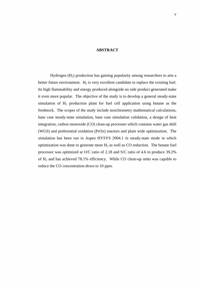
ABSTRACT
Hydrogen (H2) production has gaining popularity among researchers to aim a
better future environment. H2 is very excellent candidate to replace the existing fuel.
Its high flammability and energy produced alongside no side product generated make
it even more popular. The objective of the study is to develop a general steady-state
simulation of H2 production plant for fuel cell application using butane as the
feedstock. The scopes of the study include stoichiometry mathematical calculations,
base case steady-state simulation, base case simulation validation, a design of heat
integration, carbon monoxide (CO) clean-up processes which contains water gas shift
(WGS) and preferential oxidation (PrOx) reactors and plant wide optimization. The
simulation has been run in Aspen HYSYS 2004.1 in steady-state mode in which
optimization was done to generate more H2 as well as CO reduction. The butane fuel
processor was optimized at O/C ratio of 2.18 and S/C ratio of 4.6 to produce 39.2%
of H2 and has achieved 78.1% efficiency. While CO clean-up units was capable to
reduce the CO concentration down to 10 ppm.
vi
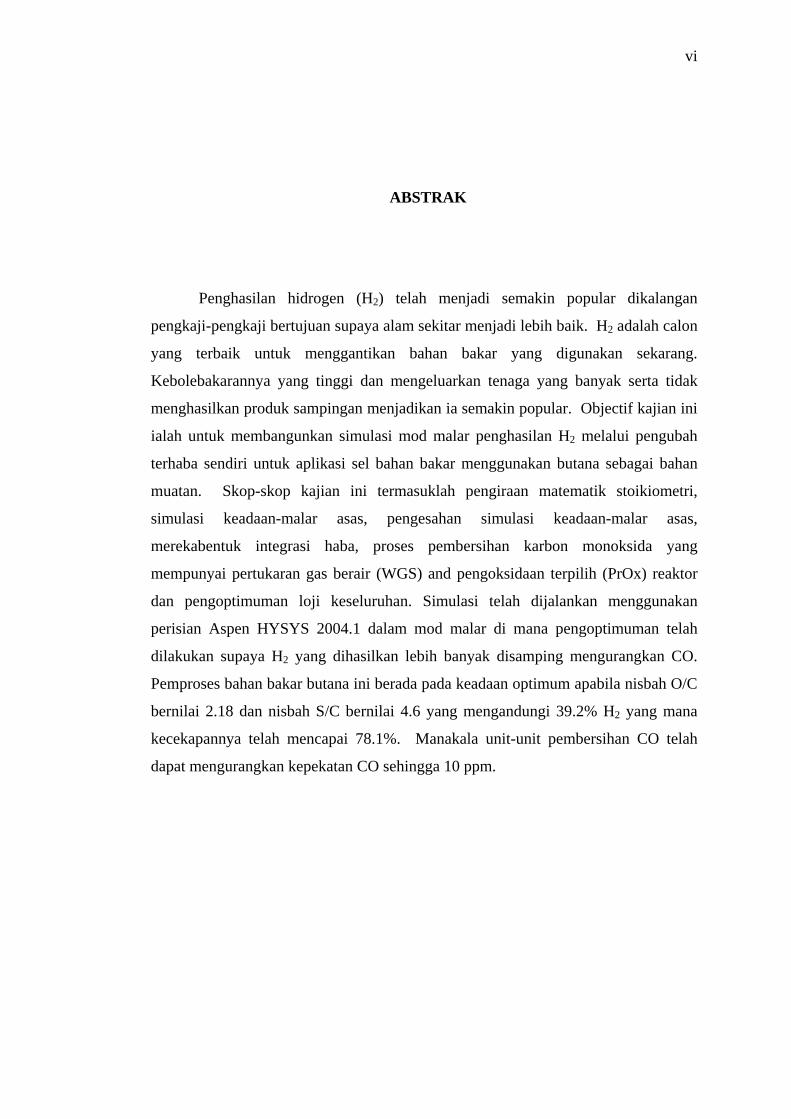
ABSTRAK
Penghasilan hidrogen (H2) telah menjadi semakin popular dikalangan
pengkaji-pengkaji bertujuan supaya alam sekitar menjadi lebih baik. H2 adalah calon
yang terbaik untuk menggantikan bahan bakar yang digunakan sekarang.
Kebolebakarannya yang tinggi dan mengeluarkan tenaga yang banyak serta tidak
menghasilkan produk sampingan menjadikan ia semakin popular. Objectif kajian ini
ialah untuk membangunkan simulasi mod malar penghasilan H2 melalui pengubah
terhaba sendiri untuk aplikasi sel bahan bakar menggunakan butana sebagai bahan
muatan. Skop-skop kajian ini termasuklah pengiraan matematik stoikiometri,
simulasi keadaan-malar asas, pengesahan simulasi keadaan-malar asas,
merekabentuk integrasi haba, proses pembersihan karbon monoksida yang
mempunyai pertukaran gas berair (WGS) and pengoksidaan terpilih (PrOx) reaktor
dan pengoptimuman loji keseluruhan. Simulasi telah dijalankan menggunakan
perisian Aspen HYSYS 2004.1 dalam mod malar di mana pengoptimuman telah
dilakukan supaya H2 yang dihasilkan lebih banyak disamping mengurangkan CO.
Pemproses bahan bakar butana ini berada pada keadaan optimum apabila nisbah O/C
bernilai 2.18 dan nisbah S/C bernilai 4.6 yang mengandungi 39.2% H2 yang mana
kecekapannya telah mencapai 78.1%. Manakala unit-unit pembersihan CO telah
dapat mengurangkan kepekatan CO sehingga 10 ppm.
vii
TABLE OF CONTENTS
CHAPTER TITLE PAGE
DECLARATION ii
DEDICATION iii
ACKNOWEDGEMENTS iv
ABSTRACT v
ABSTRAK vi
TABLE OF CONTENTS vii
LIST OF TABLES xi
LIST OF FIGURES xii
NOMENCLATURE xiv
LIST OF APPENDICES xvi
1 INTRODUCTION 1
1.1 Research Background 1
1.2 Problem Statement 2
1.3 Objective and Scopes of the Study 2
1.4 Report Organization 3
2 LITERATURE REVIEW 4
2.1 Hydrogen Characteristics 4
2.2 Fuel Cell 5
2.3 Hydrogen Production for 6
Fuel Cell Application

viii
2.3.1 Natural Gas 6
2.3.1.1 Methane 6
2.3.1.2 Ethane 7
2.3.1.3 Propane 7
2.3.1.4 Butane 8
2.3.2 Gasoline 8
2.3.3 Jet Fuel 9
2.3.4 Alcohols 9
2.3.4.1 Methanol 9
2.3.4.2 Ethanol 10
2.3.4.3 Propanol 10
2.3.5 Naphtha 11
2.4 Hydrogen Production from Butane 11
2.4.1 Steam Reforming of Butane 12
2.4.2 Partial Oxidation of Butane 12
2.4.3 Autothermal Reforming of Butane 13
2.5 Carbon Monoxide Clean-up Section 14
2.6 Steady-Simulation of Butane 15
Autothermal Reforming
2.7 Summary 15
3 METHODOLOGY 17
3.1 Research Tools 17
3.1.1 Aspen HYSYS 2004.1 17
3.2 Research Activities 18
3.2.1 Data Collection 18
3.2.2 Steady State Model Development 18
3.2.3 Steady State Model Validation 19
3.2.4 Autothermal Reforming Reactor 19
Optimization
3.2.5 Heat Integration Development 20
3.2.6 Carbon Monoxide Clean-up 20
Section Development
3.2.7 Plant Wide Optimization 20

ix
3.2 Summary 20
4 SIMULATION AND OPTIMIZATION OF 22
BUTANE AUTOTHERMAL REFORMER FOR
FUEL CELL APPLICATTON
4.1 Process Description of Butane 22
Autothermal Reforming Fuel Processor
4.2 Simulation of Butane Autothermal 23
Reforming Fuel Processor
4.2.1 Physical Properties of the 23
Pure Components
4.2.2 Thermodynamic Property 24
4.2.3 Numerical Methods Solutions 26
4.2.4 Steady State Simulation 27
4.3 Summary 27
5 RESULTS AND DISCUSSIONS
5.1 Stoichiometry Mathematical Analysis 29
5.2 Base Case of Autothermal Reforming Reactor 30
5.3 Base Case Simulation Validations 30
5.4 Autothermal reforming Reactor Optimization 31
5.5 Heat Integration 34
5.6 Carbon Monoxide Cleaning Units 34
5.6.1 Water Gas Shift Reactors 35
5.6.2 Additional Preferential Oxidation Unit 35
5.7 Plant Wide Optimization 37
5.7.1 Preferential Oxidation Inlet 38
Air Optimization
5.7.2 Further Optimization 39
5.8 Temperature and Components Profiles 40
5.8.1 Temperature Profiles of 40
Reactor Operating
5.8.2 Components Profiles in the 41
Outlet Stream
x
5.9 Fuel Processor Efficiency 42
5.10 Summary 43
6 CONCLUSIONS AND RECOMMENDATIONS
6.1 Summary 45
6.2 Conclusions 46
6.3 Recommendation for Future Works 46
REFERENCES 48
Appendices A - D 52 - 58
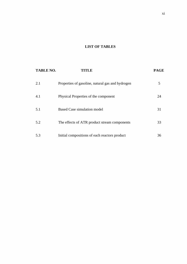
xi
LIST OF TABLES
TABLE NO. TITLE PAGE
2.1 Properties of gasoline, natural gas and hydrogen 5
4.1 Physical Properties of the component 24
5.1 Based Case simulation model 31
5.2 The effects of ATR product stream components 33
5.3 Initial compositions of each reactors product 36
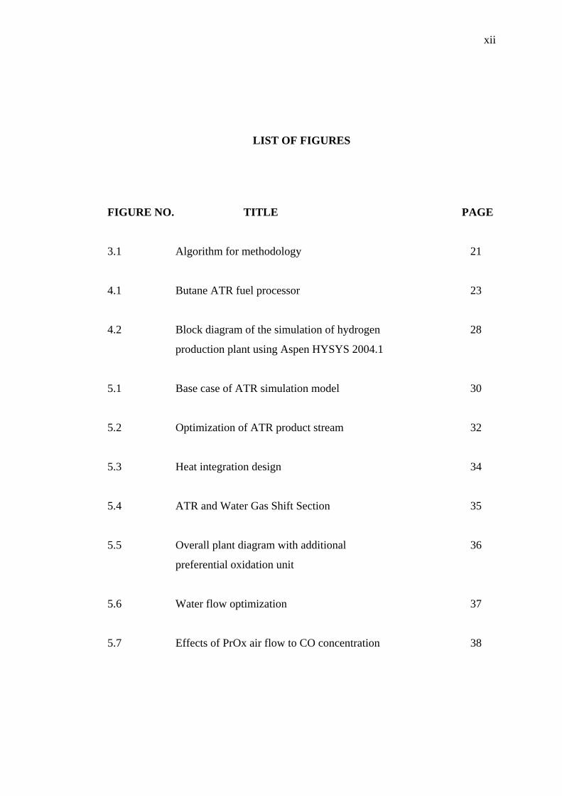
xii
LIST OF FIGURES
FIGURE NO. TITLE PAGE
3.1 Algorithm for methodology 21
4.1 Butane ATR fuel processor 23
4.2 Block diagram of the simulation of hydrogen 28
production plant using Aspen HYSYS 2004.1
5.1 Base case of ATR simulation model 30
5.2 Optimization of ATR product stream 32
5.3 Heat integration design 34
5.4 ATR and Water Gas Shift Section 35
5.5 Overall plant diagram with additional 36
preferential oxidation unit
5.6 Water flow optimization 37
5.7 Effects of PrOx air flow to CO concentration 38

xiii
5.8 Steam-to-carbon and air flow effect to 39
CO concentration
5.9 Temperature profiles of the fuel processor 41
5.10 Components profiles 42
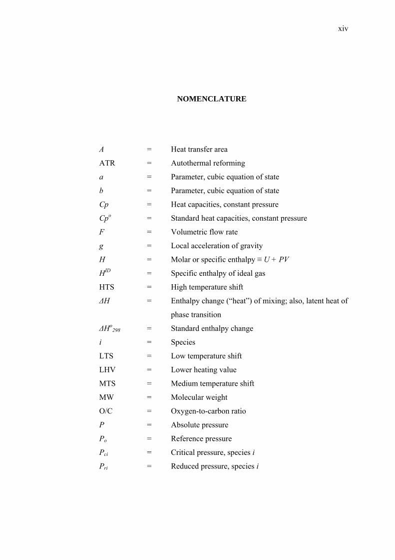
xiv
NOMENCLATURE
A = Heat transfer area
ATR = Autothermal reforming
a = Parameter, cubic equation of state
b = Parameter, cubic equation of state
Cp = Heat capacities, constant pressure
Cpo = Standard heat capacities, constant pressure
F = Volumetric flow rate
g = Local acceleration of gravity
H = Molar or specific enthalpy ≡ U + PV
HID = Specific enthalpy of ideal gas
HTS = High temperature shift
ΔH = Enthalpy change (“heat”) of mixing; also, latent heat of
phase transition
ΔHo298 = Standard enthalpy change
i = Species
LTS = Low temperature shift
LHV = Lower heating value
MTS = Medium temperature shift
MW = Molecular weight
O/C = Oxygen-to-carbon ratio
P = Absolute pressure
Po = Reference pressure
Pci = Critical pressure, species i
Pri = Reduced pressure, species i
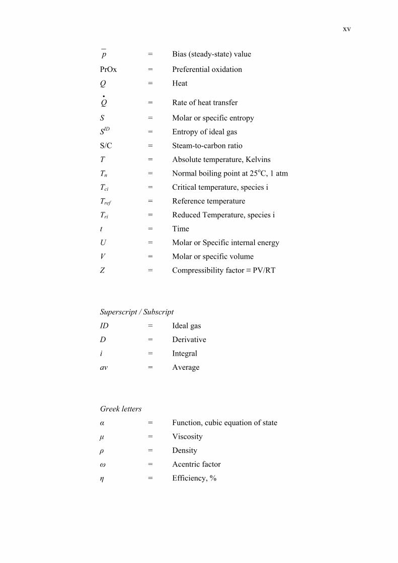
xv
p = Bias (steady-state) value
PrOx = Preferential oxidation
Q = Heat •
Q = Rate of heat transfer
S = Molar or specific entropy
SID = Entropy of ideal gas
S/C = Steam-to-carbon ratio
T = Absolute temperature, Kelvins
Tn = Normal boiling point at 25oC, 1 atm
Tci = Critical temperature, species i
Tref = Reference temperature
Tri = Reduced Temperature, species i
t = Time
U = Molar or Specific internal energy
V = Molar or specific volume
Z = Compressibility factor ≡ PV/RT
Superscript / Subscript
ID = Ideal gas
D = Derivative
i = Integral
av = Average
Greek letters
α = Function, cubic equation of state
μ = Viscosity
ρ = Density
ω = Acentric factor
η = Efficiency, %
xvi
LIST OF APPENDICES
APPENDIX TITLE PAGE
A A general fuel processor process flow diagram 52
B The effect of air molar flow to the ATR Vap Out 53
temperature
C The effect of water molar flow to the HE3 Out 54
temperature
D The overall fuel processor system condition 55

CHAPTER I
INTRODUCTION
1.1 Research Background
This study is mainly about general simulation of hydrogen (H2) production
for fuel cell application using butane as a raw material. The H2 produced will be
used in fuel-cell-powered vehicle that is known for its clean and recyclable fuel. In
fact H2 is the most abundant element that makes up over 90 percent of the matter of
universe. When it is used as fuel, it will only produce water. It is such a good
alternative to use H2 as a fuel because of its colourless, odourless and extremely
flammable gas and also the smallest and simplest member of the family of chemical
elements compared with other fuel such as hydrocarbons, alcohols, or coals (Kothari
et al., 2004).
Moreover, no side products are involved in the electrochemical conversions
of H2 with zero emission of hazardous species for instances volatile organic
compound (VOCs), nitrogen oxides (NOx) and carbon oxides (CO) (Darwish et al.,
2004). The main goal of this study is to generate H2 production on-board the vehicle
from hydrocarbon feedstock. It is better than having H2 in pressurized vessel or in
cryogenic state for the reason that safety will be the major concern. Therefore, on-
board conversion of butane into H2 through an efficient and compact fuel processor
is the main reason of this study.

2
1.2 Problem Statement
A simulation of butane reforming is scarce in the recent study for that reason
a general simulation an optimization study of hydrogen production plant had been
carried out. The aims of the study are to study preliminary design parameters for
fuel cell processor, and investigate the H2 production efficiency by using butane as a
raw material and to clean carbon monoxide (CO) that produced prior to combustion
and steam reforming reactions.
1.3 Objective and Scopes of the Study
The objective of this study is to develop a general steady-state simulation of
H2 production plant for fuel cell application using butane as the feedstock. In order
to achieve the objective, scopes as shown below have been planned.
i. Stoichiometry mathematical calculation by using overall reaction to
calculate inputs and outputs flow rate for fuel processor.
ii. Base case steady-state simulation was conducted in a selected simulator. In
this scope, the data and reactions occurred in the autothermal reforming
(ATR) reactor was set.
iii. Base case simulation validation was carried out. The purpose of this scope
was to certify the overall reactions of ATR by distinguishing between
calculated outputs composition and steady-state simulation outputs
composition.
iv. Heat integration process was made to heat up the raw material to 100oC
before entering the ATR reactor. The design of heat integration could also
minimize the heating requirement.
3
v. CO clean-up processes which contains water gas shift (WGS) and
preferential oxidation (PrOx) reactors.
vi. Plant wide optimization where high H2 generation as well as low CO
concentration is needed for better hydrogen processor efficiency.
1.4 Thesis Organization
This thesis consists of 6 chapters. In Chapter 1, the introduction of the study
is briefly discussed. While in Chapter 2 literature reviews from various sources are
deeply understood to provide correct information prior to the simulation basis. Next
is chapter 3 where the methodology of carrying the study is explained briefly. In
addition to Chapter 3, Chapter 4 has more information about the study’s
requirements. Chapter 5 has the results and discussion of the simulation that indicate
how the scopes of the study are achieved. To summarize this study, Chapter 6 was
done to conclude the study and some recommendations were made.

48
REFERENCES
Aartun, I., Gjervan, T., Venvik, H., Görke, O., Pfeifer, P., Fathi, M., Holmena, A.
and Schubert, K. (2004). “Catalytic Conversion of Propane to Hydrogen in
Microstructured Reactors.” Chemical Engineering Journal. 101. 93–99.
Ahmet, K., Gamman, J. and Foger, K. (2002). “Demonstration of LPG-fueled Solid
Oxide Fuel Cell Systems.” Solid State Ionics. 152-153. 485-492.
Aspen Tech. Aspen HYSYS 2004.1 Documentation. Avci, A. K., Trimm, D. L. Aksoylu, A. E. and Onsan, Z. I. (2004). “Hydrogen
Production by Steam Reforming of N-butane over Supported Ni and Pt-Ni
Catalysts.” Applied Catalysis A: General. 258. 235-240.
Basile, A., Gallucci, F. and Paturzo, L. (2005). “Hydrogen Production from
Methanol by Oxidative Steam Reforming Carried out in a Membrane
Reactor.” Catalysis Today. 104. 251-259.
Caglayan, B. S., Avcı, A. K., Onsan, Z. I. and Aksoylu, A. E. (2005). “Production of
Hydrogen over Bimetallic Pt–Ni/d-Al2O3 I. Indirect Partial Oxidation of
Propane.” Applied Catalysis A: General. 280. 181–188.
Chin, S. Y., Chin, Y. H. and Amiridis, M. D. (2006). “Hydrogen Production via the
Catalytic Cracking of Ethane over Ni/SiO2 Catalysts.” Applied Catalysis A:
General. 300. 8-13.
Choudhary, T. V., Sivadinarayana, C., Chusuei, C. C., Klinghoffer, A. and
Goodman, D. W. (2001). “Hydrogen Production via Catalytic
Decomposition of Methane.” Journal of Catalysis. 199. 9-18.
Cipitı, F., Recupero, V. Pino, L., Vita, A. and Lagan, M. (2006). “Experimental
Analysis of a 2kWe LPG-based Fuel Processor for Polymer Electrolyte Fuel
Cells.” Journal of Power Sources. 157. 914-920.
Comas, J., Laborde, M. and Amadeo, N. (2004). “Thermodynamic Analysis of
Hydrogen Production from Ethanol using CaO as a CO2 Sorbent.” Journal of
Power Sources. 138. 61-67.

49
Darwish, N. A., Hilal, N., Versteeg, G. and Heesink, B. (2004). “Feasibility of the
Direct Generation of Hydrogen for Fuel-cell-powered Vehicles On-board
Steam Reforming of Naphtha.” Fuel. 83. 409-417.
Dong, W. S., Roh, H. S., Liu, Z. W., Jun, K. W. and Park, S. E. (2001). “Hydrogen
Production from Methane Reforming Reactions over Ni/MgO Catalyst.”
Bull. Korean Chem. Soc. 22, No. 12. 1323-1327.
Ersoz, A., Olgun, H., Ozdogan, S., Gungor, C., Akgun, F. and Tiris, M. (2003).
“Autothermal Reforming as a Hydrocarbon Fuel Processing Option for PEM
Fuel Cell.” Power Sources. 118. 384-392.
Fraser, S.D., Monsberger, M. and Hacker, V. (2006). “A Thermodynamic Analysis
of the Reformer Sponge Iron Cycle.” Journal of Power Sources. 161. 420-
431.
Galvita, V. and Sunmacher K. (2005) “Hydrogen Production from Methane by
Steam Reforming in a Periodically Operated Two-layer Catalytic Reactor.”
Applied Catalysis A: General. 289. 121-127.
Goula, M. A., Kontou, S. K. and Tsiakaras, P. E. (2004). “Hydrogen Production by
Ethanol Steam Reforming over a Commercial Pd/ γ-Al2O3 Catalyst.”
Applied Catalysis B: Environmental. 49. 135-144.
Junge, H. and Beller, M. (2005). “Ruthenium-catalyzed Generation of Hydrogen
from Iso-propanol.” Tetrahedron Letters. 46. 1031-1034.
Karagiannakis, G., Kokkofitis, C., Zisekas, S. and Stoukides, M. (2005). “Catalytic
and Electrocatalytic Production of H2 from Propane Decomposition over Pt
and Pd in a Proton-conducting Membrane-reactor.” Catalysis Today. 104.
219-224.
Kothari, R., Buddhi, D. and Sawhney, R. L. (2004). “Sources and Technology for
Hydrogen Production: a Review.” Int. J. Global Energy. 21, Nos. 1/2. 154-
178.
Lattner, J. R. and Harold, M. P. (2004). “Comparison of Conventional and
Membrane Reactor Fuel Processors for Hydrocarbon-based PEM Fuel Cell
Systems.” International Journal of Hydrogen Energy. 29. 393-417.
Lin, A. T., Chen, Y. H., Yu, C. C., Liu, Y. C. and Lee, C. H. (2006). “Dynamic
Modeling and Control Structure Design of an Experimental Fuel Processor.”
International Journal of Hydrogen Energy. 31. 413-426.

50
Liu, S., Takahashi, K., Fuchigami, K. and Uematsu, K. (2006). “Hydrogen
Production by Oxidative Methanol Reforming on Pd/ZnO: Catalyst
Deactivation.” Applied Catalysis A: General. 299. 58-65.
Mattos, L. V. and Noronha, F.B., (2005). “Hydrogen Production for Fuel Cell
Applications by Ethanol Partial Oxidation on Pt/CeO2 Catalysts: The Effect
of the Reaction Conditions and Reaction Mechanism.” Journal of Catalysis.
233. 453-463.
Minutillo, M. (2005). “On-board Fuel Processor Modelling for Hydrogen-enriched
Gasoline Fuelled Engine.” International Journal of Hydrogen Energy. 30.
1483-1490.
Mizuno, T., Matsumura, Y., Nakajima, T. and Mishima, S. (2003). “Effect of
Support on Catalytic Properties of Rh Catalysts for Steam Reforming of
2-Propanol.” International Journal of Hydrogen Energy. 28. 1393-1399.
Nakagawa, K., Mikka, N. G. and Ando, T. (2005). “Hydrogen Production from
Methane for Fuel Cell Using Oxidized Diamond-supported Catalysts.”
International Journal of Hydrogen Energy. 30. 201-207.
Otsuka, K., Shigeta, Y. and Takenaka, S. (2002). “Production of Hydrogen from
Gasoline Range Alkanes with Reduced CO2 Emission.” International Journal
of Hydrogen Energy. 27. 11-18.
Recupero, V., Pino, L., Vita, A., Cipiti, F., Cordaro, M. and Lagane, M. (2005).
“Development of a LPG Fuel Cell Processor for PEFC Systems: Laboratory
Scale Evaluation of Autothermal Reforming and Preferential Oxidation
Subunits.” International Journal of Hydrogen Energy. 30. 963-971.
Soo, Y. C., Chin, Y. H. and Amiridis, M. D. (2006). “Hydrogen Production via the
Catalytic Cracking of Ethane over Ni/SiO2.” Applied Catalysis A: General.
300. 8-13.
Suzuki, T., Iwanami, H. and Yoshinari, T. (2000). “Steam Reforming of Kerosene
on Ru/Al2O3 Catalyst to Yield Hydrogen.” International Journal of Hydrogen
Energy. 25. 119-126.
Steinberg, M. (2006). “Conversion of Fossil and Biomass Fuel to Electric Power and
transportation Fuel by high Efficiency Integrated Plasma Fuel Cell (IPFC)
Energy Cycle.” International Journal of Hydrogen Energy. 31. 405-411.

51
Wang, Y. N. and Rodrigues, A. E. (2005) “Hydrogen Production from Steam
Methane Reforming Coupled with in situ CO2 Capture: Conceptual
Parametric Study.” Fuel. 84. 1778-1789.
Xu, Y., Kameoka, S., Kishida, K. Demura, M., Tsai, A. and Hirano, T. (2005).
“Catalytic Properties of Alkali-leached Ni3Al for Hydrogen Production from
Methanol.” Intermetallics. 13. 151-155.
Ye, Y., Liisa, R. S., Munder, B. and Sundmacher, K. (2005). “Partial Oxidation of
N-butane in a Solid Electrolyte Membrane Reactor: Periodic and Steady-state
Operations.” Applied Catalysis A: General. 285. 86-95.


