
L
Ä.>ZVä
1329
5753
8400
Inverter
Inverter Drives 8400 BaseLine C _ _ _ _ _ _ _ _ _ _ _ _ _ _ Reference manual EN
E84AVBCxxxxx...
2 Lenze · 8400 BaseLine C · Reference manual · DMS 1.6 EN · 01/2014 · TD05
_ _ _ _ _ _ _ _ _ _ _ _ _ _ _ _ _ _ _ _ _ _ _ _ _ _ _ _ _ _ _ _ _ _ _ _ _ _ _ _ _ _ _ _ _ _ _ _ _ _ _ _ _ _ _ _ _ _ _ _ _ _ _ _
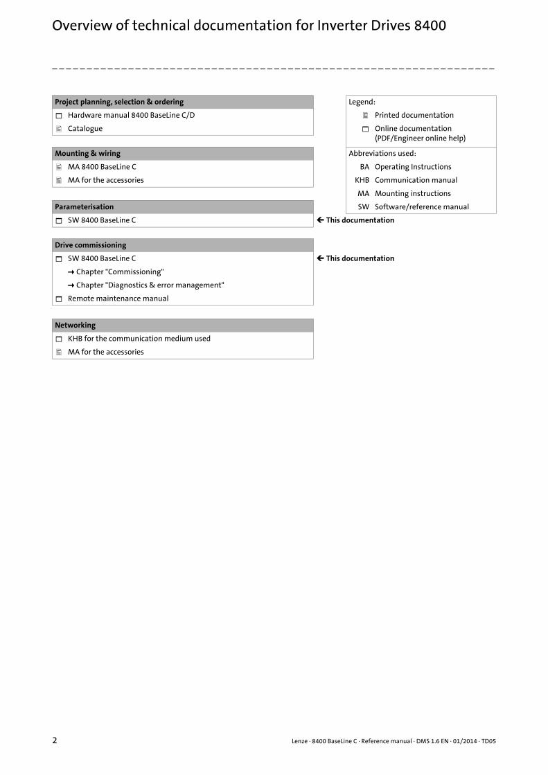
Project planning, selection & ordering Legend:
Hardware manual 8400 BaseLine C/D Printed documentation
Catalogue Online documentation(PDF/Engineer online help)
Mounting & wiring Abbreviations used:
MA 8400 BaseLine C BA Operating Instructions
MA for the accessories KHB Communication manual
MA Mounting instructions
Parameterisation SW Software/reference manual
SW 8400 BaseLine C This documentation
Drive commissioning
SW 8400 BaseLine C This documentation
Chapter "Commissioning"
Chapter "Diagnostics & error management"
Remote maintenance manual
Networking
KHB for the communication medium used
MA for the accessories
Overview of technical documentation for Inverter Drives 8400
Lenze · 8400 BaseLine C · Reference manual · DMS 1.6 EN · 01/2014 · TD05 3
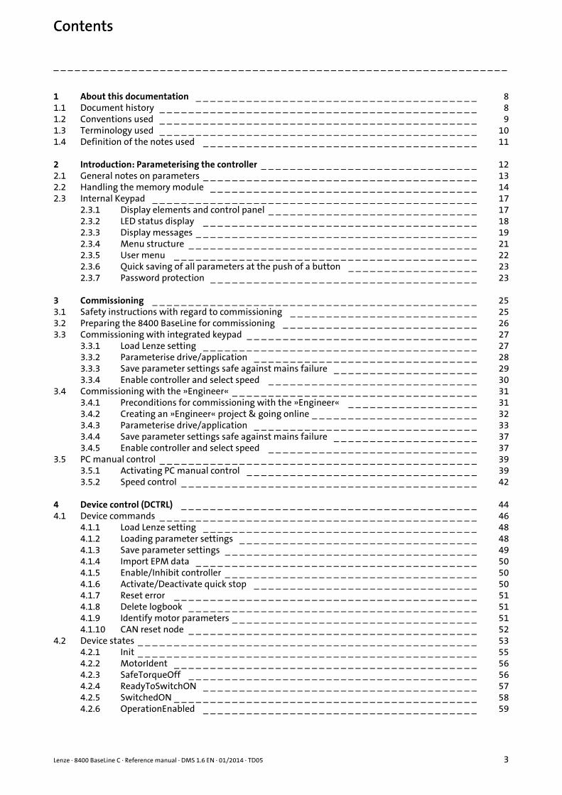
Contents
_ _ _ _ _ _ _ _ _ _ _ _ _ _ _ _ _ _ _ _ _ _ _ _ _ _ _ _ _ _ _ _ _ _ _ _ _ _ _ _ _ _ _ _ _ _ _ _ _ _ _ _ _ _ _ _ _ _ _ _ _ _ _ _
1 About this documentation _ _ _ _ _ _ _ _ _ _ _ _ _ _ _ _ _ _ _ _ _ _ _ _ _ _ _ _ _ _ _ _ _ _ _ _ _ _ _ 81.1 Document history _ _ _ _ _ _ _ _ _ _ _ _ _ _ _ _ _ _ _ _ _ _ _ _ _ _ _ _ _ _ _ _ _ _ _ _ _ _ _ _ _ _ _ _ 81.2 Conventions used _ _ _ _ _ _ _ _ _ _ _ _ _ _ _ _ _ _ _ _ _ _ _ _ _ _ _ _ _ _ _ _ _ _ _ _ _ _ _ _ _ _ _ _ 91.3 Terminology used _ _ _ _ _ _ _ _ _ _ _ _ _ _ _ _ _ _ _ _ _ _ _ _ _ _ _ _ _ _ _ _ _ _ _ _ _ _ _ _ _ _ _ _ 101.4 Definition of the notes used _ _ _ _ _ _ _ _ _ _ _ _ _ _ _ _ _ _ _ _ _ _ _ _ _ _ _ _ _ _ _ _ _ _ _ _ _ _ 11
2 Introduction: Parameterising the controller _ _ _ _ _ _ _ _ _ _ _ _ _ _ _ _ _ _ _ _ _ _ _ _ _ _ _ _ _ _ 122.1 General notes on parameters _ _ _ _ _ _ _ _ _ _ _ _ _ _ _ _ _ _ _ _ _ _ _ _ _ _ _ _ _ _ _ _ _ _ _ _ _ _ 132.2 Handling the memory module _ _ _ _ _ _ _ _ _ _ _ _ _ _ _ _ _ _ _ _ _ _ _ _ _ _ _ _ _ _ _ _ _ _ _ _ _ 142.3 Internal Keypad _ _ _ _ _ _ _ _ _ _ _ _ _ _ _ _ _ _ _ _ _ _ _ _ _ _ _ _ _ _ _ _ _ _ _ _ _ _ _ _ _ _ _ _ _ 17
2.3.1 Display elements and control panel _ _ _ _ _ _ _ _ _ _ _ _ _ _ _ _ _ _ _ _ _ _ _ _ _ _ _ _ _ 172.3.2 LED status display _ _ _ _ _ _ _ _ _ _ _ _ _ _ _ _ _ _ _ _ _ _ _ _ _ _ _ _ _ _ _ _ _ _ _ _ _ _ 182.3.3 Display messages _ _ _ _ _ _ _ _ _ _ _ _ _ _ _ _ _ _ _ _ _ _ _ _ _ _ _ _ _ _ _ _ _ _ _ _ _ _ _ 192.3.4 Menu structure _ _ _ _ _ _ _ _ _ _ _ _ _ _ _ _ _ _ _ _ _ _ _ _ _ _ _ _ _ _ _ _ _ _ _ _ _ _ _ _ 212.3.5 User menu _ _ _ _ _ _ _ _ _ _ _ _ _ _ _ _ _ _ _ _ _ _ _ _ _ _ _ _ _ _ _ _ _ _ _ _ _ _ _ _ _ _ 222.3.6 Quick saving of all parameters at the push of a button _ _ _ _ _ _ _ _ _ _ _ _ _ _ _ _ _ _ 232.3.7 Password protection _ _ _ _ _ _ _ _ _ _ _ _ _ _ _ _ _ _ _ _ _ _ _ _ _ _ _ _ _ _ _ _ _ _ _ _ _ 23
3 Commissioning _ _ _ _ _ _ _ _ _ _ _ _ _ _ _ _ _ _ _ _ _ _ _ _ _ _ _ _ _ _ _ _ _ _ _ _ _ _ _ _ _ _ _ _ _ 253.1 Safety instructions with regard to commissioning _ _ _ _ _ _ _ _ _ _ _ _ _ _ _ _ _ _ _ _ _ _ _ _ _ _ 253.2 Preparing the 8400 BaseLine for commissioning _ _ _ _ _ _ _ _ _ _ _ _ _ _ _ _ _ _ _ _ _ _ _ _ _ _ _ 263.3 Commissioning with integrated keypad _ _ _ _ _ _ _ _ _ _ _ _ _ _ _ _ _ _ _ _ _ _ _ _ _ _ _ _ _ _ _ _ 27
3.3.1 Load Lenze setting _ _ _ _ _ _ _ _ _ _ _ _ _ _ _ _ _ _ _ _ _ _ _ _ _ _ _ _ _ _ _ _ _ _ _ _ _ _ 273.3.2 Parameterise drive/application _ _ _ _ _ _ _ _ _ _ _ _ _ _ _ _ _ _ _ _ _ _ _ _ _ _ _ _ _ _ _ 283.3.3 Save parameter settings safe against mains failure _ _ _ _ _ _ _ _ _ _ _ _ _ _ _ _ _ _ _ _ 293.3.4 Enable controller and select speed _ _ _ _ _ _ _ _ _ _ _ _ _ _ _ _ _ _ _ _ _ _ _ _ _ _ _ _ _ 30
3.4 Commissioning with the »Engineer« _ _ _ _ _ _ _ _ _ _ _ _ _ _ _ _ _ _ _ _ _ _ _ _ _ _ _ _ _ _ _ _ _ _ 313.4.1 Preconditions for commissioning with the »Engineer« _ _ _ _ _ _ _ _ _ _ _ _ _ _ _ _ _ _ 313.4.2 Creating an »Engineer« project & going online _ _ _ _ _ _ _ _ _ _ _ _ _ _ _ _ _ _ _ _ _ _ _ 323.4.3 Parameterise drive/application _ _ _ _ _ _ _ _ _ _ _ _ _ _ _ _ _ _ _ _ _ _ _ _ _ _ _ _ _ _ _ 333.4.4 Save parameter settings safe against mains failure _ _ _ _ _ _ _ _ _ _ _ _ _ _ _ _ _ _ _ _ 373.4.5 Enable controller and select speed _ _ _ _ _ _ _ _ _ _ _ _ _ _ _ _ _ _ _ _ _ _ _ _ _ _ _ _ _ 37
3.5 PC manual control _ _ _ _ _ _ _ _ _ _ _ _ _ _ _ _ _ _ _ _ _ _ _ _ _ _ _ _ _ _ _ _ _ _ _ _ _ _ _ _ _ _ _ _ 393.5.1 Activating PC manual control _ _ _ _ _ _ _ _ _ _ _ _ _ _ _ _ _ _ _ _ _ _ _ _ _ _ _ _ _ _ _ _ 393.5.2 Speed control _ _ _ _ _ _ _ _ _ _ _ _ _ _ _ _ _ _ _ _ _ _ _ _ _ _ _ _ _ _ _ _ _ _ _ _ _ _ _ _ _ 42
4 Device control (DCTRL) _ _ _ _ _ _ _ _ _ _ _ _ _ _ _ _ _ _ _ _ _ _ _ _ _ _ _ _ _ _ _ _ _ _ _ _ _ _ _ _ _ 444.1 Device commands _ _ _ _ _ _ _ _ _ _ _ _ _ _ _ _ _ _ _ _ _ _ _ _ _ _ _ _ _ _ _ _ _ _ _ _ _ _ _ _ _ _ _ _ 46
4.1.1 Load Lenze setting _ _ _ _ _ _ _ _ _ _ _ _ _ _ _ _ _ _ _ _ _ _ _ _ _ _ _ _ _ _ _ _ _ _ _ _ _ _ 484.1.2 Loading parameter settings _ _ _ _ _ _ _ _ _ _ _ _ _ _ _ _ _ _ _ _ _ _ _ _ _ _ _ _ _ _ _ _ _ 484.1.3 Save parameter settings _ _ _ _ _ _ _ _ _ _ _ _ _ _ _ _ _ _ _ _ _ _ _ _ _ _ _ _ _ _ _ _ _ _ _ 494.1.4 Import EPM data _ _ _ _ _ _ _ _ _ _ _ _ _ _ _ _ _ _ _ _ _ _ _ _ _ _ _ _ _ _ _ _ _ _ _ _ _ _ _ 504.1.5 Enable/Inhibit controller _ _ _ _ _ _ _ _ _ _ _ _ _ _ _ _ _ _ _ _ _ _ _ _ _ _ _ _ _ _ _ _ _ _ _ 504.1.6 Activate/Deactivate quick stop _ _ _ _ _ _ _ _ _ _ _ _ _ _ _ _ _ _ _ _ _ _ _ _ _ _ _ _ _ _ _ 504.1.7 Reset error _ _ _ _ _ _ _ _ _ _ _ _ _ _ _ _ _ _ _ _ _ _ _ _ _ _ _ _ _ _ _ _ _ _ _ _ _ _ _ _ _ _ 514.1.8 Delete logbook _ _ _ _ _ _ _ _ _ _ _ _ _ _ _ _ _ _ _ _ _ _ _ _ _ _ _ _ _ _ _ _ _ _ _ _ _ _ _ _ 514.1.9 Identify motor parameters _ _ _ _ _ _ _ _ _ _ _ _ _ _ _ _ _ _ _ _ _ _ _ _ _ _ _ _ _ _ _ _ _ _ 514.1.10 CAN reset node _ _ _ _ _ _ _ _ _ _ _ _ _ _ _ _ _ _ _ _ _ _ _ _ _ _ _ _ _ _ _ _ _ _ _ _ _ _ _ _ 52
4.2 Device states _ _ _ _ _ _ _ _ _ _ _ _ _ _ _ _ _ _ _ _ _ _ _ _ _ _ _ _ _ _ _ _ _ _ _ _ _ _ _ _ _ _ _ _ _ _ _ 534.2.1 Init _ _ _ _ _ _ _ _ _ _ _ _ _ _ _ _ _ _ _ _ _ _ _ _ _ _ _ _ _ _ _ _ _ _ _ _ _ _ _ _ _ _ _ _ _ _ _ 554.2.2 MotorIdent _ _ _ _ _ _ _ _ _ _ _ _ _ _ _ _ _ _ _ _ _ _ _ _ _ _ _ _ _ _ _ _ _ _ _ _ _ _ _ _ _ _ 564.2.3 SafeTorqueOff _ _ _ _ _ _ _ _ _ _ _ _ _ _ _ _ _ _ _ _ _ _ _ _ _ _ _ _ _ _ _ _ _ _ _ _ _ _ _ _ 564.2.4 ReadyToSwitchON _ _ _ _ _ _ _ _ _ _ _ _ _ _ _ _ _ _ _ _ _ _ _ _ _ _ _ _ _ _ _ _ _ _ _ _ _ _ 574.2.5 SwitchedON _ _ _ _ _ _ _ _ _ _ _ _ _ _ _ _ _ _ _ _ _ _ _ _ _ _ _ _ _ _ _ _ _ _ _ _ _ _ _ _ _ _ 584.2.6 OperationEnabled _ _ _ _ _ _ _ _ _ _ _ _ _ _ _ _ _ _ _ _ _ _ _ _ _ _ _ _ _ _ _ _ _ _ _ _ _ _ 59
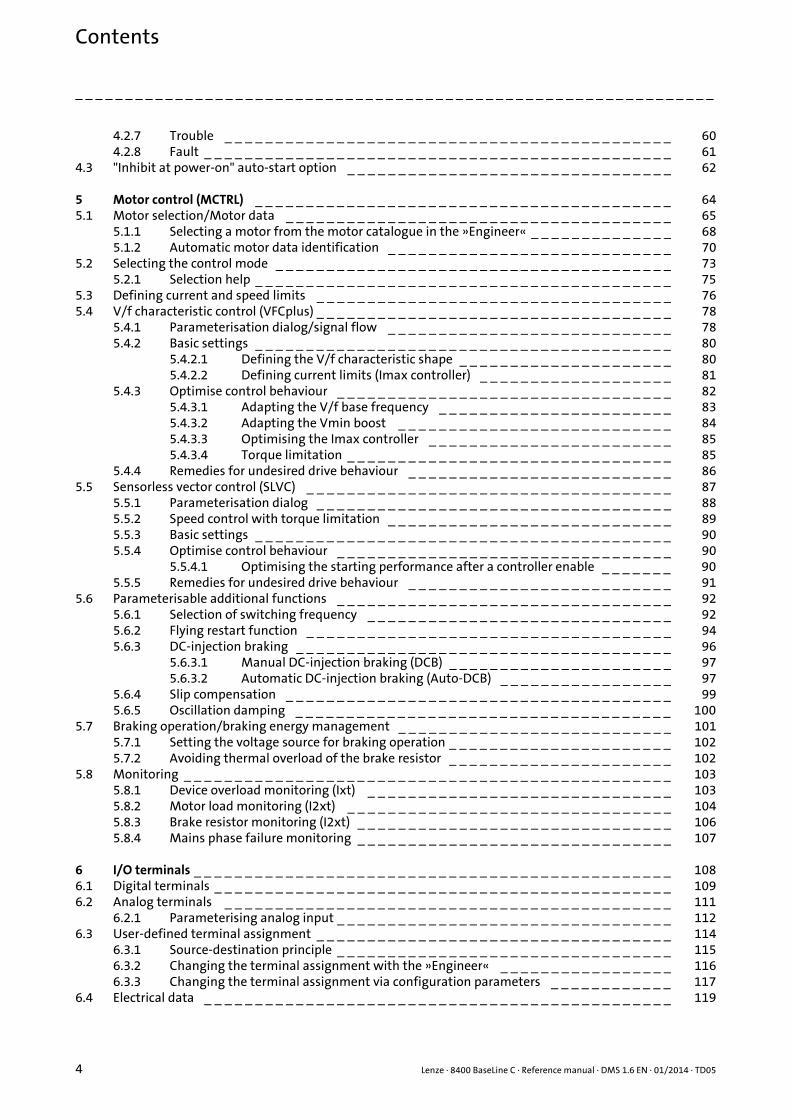
Contents
Contents
4 Lenze · 8400 BaseLine C · Reference manual · DMS 1.6 EN · 01/2014 · TD05
_ _ _ _ _ _ _ _ _ _ _ _ _ _ _ _ _ _ _ _ _ _ _ _ _ _ _ _ _ _ _ _ _ _ _ _ _ _ _ _ _ _ _ _ _ _ _ _ _ _ _ _ _ _ _ _ _ _ _ _ _ _ _ _
4.2.7 Trouble _ _ _ _ _ _ _ _ _ _ _ _ _ _ _ _ _ _ _ _ _ _ _ _ _ _ _ _ _ _ _ _ _ _ _ _ _ _ _ _ _ _ _ _ 604.2.8 Fault _ _ _ _ _ _ _ _ _ _ _ _ _ _ _ _ _ _ _ _ _ _ _ _ _ _ _ _ _ _ _ _ _ _ _ _ _ _ _ _ _ _ _ _ _ _ 61
4.3 "Inhibit at power-on" auto-start option _ _ _ _ _ _ _ _ _ _ _ _ _ _ _ _ _ _ _ _ _ _ _ _ _ _ _ _ _ _ _ _ 62
5 Motor control (MCTRL) _ _ _ _ _ _ _ _ _ _ _ _ _ _ _ _ _ _ _ _ _ _ _ _ _ _ _ _ _ _ _ _ _ _ _ _ _ _ _ _ _ 645.1 Motor selection/Motor data _ _ _ _ _ _ _ _ _ _ _ _ _ _ _ _ _ _ _ _ _ _ _ _ _ _ _ _ _ _ _ _ _ _ _ _ _ _ 65
5.1.1 Selecting a motor from the motor catalogue in the »Engineer« _ _ _ _ _ _ _ _ _ _ _ _ _ _ 685.1.2 Automatic motor data identification _ _ _ _ _ _ _ _ _ _ _ _ _ _ _ _ _ _ _ _ _ _ _ _ _ _ _ _ 70
5.2 Selecting the control mode _ _ _ _ _ _ _ _ _ _ _ _ _ _ _ _ _ _ _ _ _ _ _ _ _ _ _ _ _ _ _ _ _ _ _ _ _ _ _ 735.2.1 Selection help _ _ _ _ _ _ _ _ _ _ _ _ _ _ _ _ _ _ _ _ _ _ _ _ _ _ _ _ _ _ _ _ _ _ _ _ _ _ _ _ _ 75
5.3 Defining current and speed limits _ _ _ _ _ _ _ _ _ _ _ _ _ _ _ _ _ _ _ _ _ _ _ _ _ _ _ _ _ _ _ _ _ _ _ 765.4 V/f characteristic control (VFCplus) _ _ _ _ _ _ _ _ _ _ _ _ _ _ _ _ _ _ _ _ _ _ _ _ _ _ _ _ _ _ _ _ _ _ _ 78
5.4.1 Parameterisation dialog/signal flow _ _ _ _ _ _ _ _ _ _ _ _ _ _ _ _ _ _ _ _ _ _ _ _ _ _ _ _ 785.4.2 Basic settings _ _ _ _ _ _ _ _ _ _ _ _ _ _ _ _ _ _ _ _ _ _ _ _ _ _ _ _ _ _ _ _ _ _ _ _ _ _ _ _ _ 80
5.4.2.1 Defining the V/f characteristic shape _ _ _ _ _ _ _ _ _ _ _ _ _ _ _ _ _ _ _ _ _ 805.4.2.2 Defining current limits (Imax controller) _ _ _ _ _ _ _ _ _ _ _ _ _ _ _ _ _ _ _ 81
5.4.3 Optimise control behaviour _ _ _ _ _ _ _ _ _ _ _ _ _ _ _ _ _ _ _ _ _ _ _ _ _ _ _ _ _ _ _ _ _ 825.4.3.1 Adapting the V/f base frequency _ _ _ _ _ _ _ _ _ _ _ _ _ _ _ _ _ _ _ _ _ _ _ 835.4.3.2 Adapting the Vmin boost _ _ _ _ _ _ _ _ _ _ _ _ _ _ _ _ _ _ _ _ _ _ _ _ _ _ _ 845.4.3.3 Optimising the Imax controller _ _ _ _ _ _ _ _ _ _ _ _ _ _ _ _ _ _ _ _ _ _ _ _ 855.4.3.4 Torque limitation _ _ _ _ _ _ _ _ _ _ _ _ _ _ _ _ _ _ _ _ _ _ _ _ _ _ _ _ _ _ _ _ 85
5.4.4 Remedies for undesired drive behaviour _ _ _ _ _ _ _ _ _ _ _ _ _ _ _ _ _ _ _ _ _ _ _ _ _ _ 865.5 Sensorless vector control (SLVC) _ _ _ _ _ _ _ _ _ _ _ _ _ _ _ _ _ _ _ _ _ _ _ _ _ _ _ _ _ _ _ _ _ _ _ _ 87
5.5.1 Parameterisation dialog _ _ _ _ _ _ _ _ _ _ _ _ _ _ _ _ _ _ _ _ _ _ _ _ _ _ _ _ _ _ _ _ _ _ _ 885.5.2 Speed control with torque limitation _ _ _ _ _ _ _ _ _ _ _ _ _ _ _ _ _ _ _ _ _ _ _ _ _ _ _ _ 895.5.3 Basic settings _ _ _ _ _ _ _ _ _ _ _ _ _ _ _ _ _ _ _ _ _ _ _ _ _ _ _ _ _ _ _ _ _ _ _ _ _ _ _ _ _ 905.5.4 Optimise control behaviour _ _ _ _ _ _ _ _ _ _ _ _ _ _ _ _ _ _ _ _ _ _ _ _ _ _ _ _ _ _ _ _ _ 90
5.5.4.1 Optimising the starting performance after a controller enable _ _ _ _ _ _ _ 905.5.5 Remedies for undesired drive behaviour _ _ _ _ _ _ _ _ _ _ _ _ _ _ _ _ _ _ _ _ _ _ _ _ _ _ 91
5.6 Parameterisable additional functions _ _ _ _ _ _ _ _ _ _ _ _ _ _ _ _ _ _ _ _ _ _ _ _ _ _ _ _ _ _ _ _ _ 925.6.1 Selection of switching frequency _ _ _ _ _ _ _ _ _ _ _ _ _ _ _ _ _ _ _ _ _ _ _ _ _ _ _ _ _ _ 925.6.2 Flying restart function _ _ _ _ _ _ _ _ _ _ _ _ _ _ _ _ _ _ _ _ _ _ _ _ _ _ _ _ _ _ _ _ _ _ _ _ 945.6.3 DC-injection braking _ _ _ _ _ _ _ _ _ _ _ _ _ _ _ _ _ _ _ _ _ _ _ _ _ _ _ _ _ _ _ _ _ _ _ _ _ 96
5.6.3.1 Manual DC-injection braking (DCB) _ _ _ _ _ _ _ _ _ _ _ _ _ _ _ _ _ _ _ _ _ _ 975.6.3.2 Automatic DC-injection braking (Auto-DCB) _ _ _ _ _ _ _ _ _ _ _ _ _ _ _ _ _ 97
5.6.4 Slip compensation _ _ _ _ _ _ _ _ _ _ _ _ _ _ _ _ _ _ _ _ _ _ _ _ _ _ _ _ _ _ _ _ _ _ _ _ _ _ 995.6.5 Oscillation damping _ _ _ _ _ _ _ _ _ _ _ _ _ _ _ _ _ _ _ _ _ _ _ _ _ _ _ _ _ _ _ _ _ _ _ _ _ 100
5.7 Braking operation/braking energy management _ _ _ _ _ _ _ _ _ _ _ _ _ _ _ _ _ _ _ _ _ _ _ _ _ _ _ 1015.7.1 Setting the voltage source for braking operation _ _ _ _ _ _ _ _ _ _ _ _ _ _ _ _ _ _ _ _ _ _ 1025.7.2 Avoiding thermal overload of the brake resistor _ _ _ _ _ _ _ _ _ _ _ _ _ _ _ _ _ _ _ _ _ _ 102
5.8 Monitoring _ _ _ _ _ _ _ _ _ _ _ _ _ _ _ _ _ _ _ _ _ _ _ _ _ _ _ _ _ _ _ _ _ _ _ _ _ _ _ _ _ _ _ _ _ _ _ _ 1035.8.1 Device overload monitoring (Ixt) _ _ _ _ _ _ _ _ _ _ _ _ _ _ _ _ _ _ _ _ _ _ _ _ _ _ _ _ _ _ 1035.8.2 Motor load monitoring (I2xt) _ _ _ _ _ _ _ _ _ _ _ _ _ _ _ _ _ _ _ _ _ _ _ _ _ _ _ _ _ _ _ _ 1045.8.3 Brake resistor monitoring (I2xt) _ _ _ _ _ _ _ _ _ _ _ _ _ _ _ _ _ _ _ _ _ _ _ _ _ _ _ _ _ _ _ 1065.8.4 Mains phase failure monitoring _ _ _ _ _ _ _ _ _ _ _ _ _ _ _ _ _ _ _ _ _ _ _ _ _ _ _ _ _ _ _ 107
6 I/O terminals _ _ _ _ _ _ _ _ _ _ _ _ _ _ _ _ _ _ _ _ _ _ _ _ _ _ _ _ _ _ _ _ _ _ _ _ _ _ _ _ _ _ _ _ _ _ _ 1086.1 Digital terminals _ _ _ _ _ _ _ _ _ _ _ _ _ _ _ _ _ _ _ _ _ _ _ _ _ _ _ _ _ _ _ _ _ _ _ _ _ _ _ _ _ _ _ _ _ 1096.2 Analog terminals _ _ _ _ _ _ _ _ _ _ _ _ _ _ _ _ _ _ _ _ _ _ _ _ _ _ _ _ _ _ _ _ _ _ _ _ _ _ _ _ _ _ _ _ 111
6.2.1 Parameterising analog input _ _ _ _ _ _ _ _ _ _ _ _ _ _ _ _ _ _ _ _ _ _ _ _ _ _ _ _ _ _ _ _ _ 1126.3 User-defined terminal assignment _ _ _ _ _ _ _ _ _ _ _ _ _ _ _ _ _ _ _ _ _ _ _ _ _ _ _ _ _ _ _ _ _ _ _ 114
6.3.1 Source-destination principle _ _ _ _ _ _ _ _ _ _ _ _ _ _ _ _ _ _ _ _ _ _ _ _ _ _ _ _ _ _ _ _ _ 1156.3.2 Changing the terminal assignment with the »Engineer« _ _ _ _ _ _ _ _ _ _ _ _ _ _ _ _ _ 1166.3.3 Changing the terminal assignment via configuration parameters _ _ _ _ _ _ _ _ _ _ _ _ 117
6.4 Electrical data _ _ _ _ _ _ _ _ _ _ _ _ _ _ _ _ _ _ _ _ _ _ _ _ _ _ _ _ _ _ _ _ _ _ _ _ _ _ _ _ _ _ _ _ _ _ 119

Lenze · 8400 BaseLine C · Reference manual · DMS 1.6 EN · 01/2014 · TD05 5
Contents
_ _ _ _ _ _ _ _ _ _ _ _ _ _ _ _ _ _ _ _ _ _ _ _ _ _ _ _ _ _ _ _ _ _ _ _ _ _ _ _ _ _ _ _ _ _ _ _ _ _ _ _ _ _ _ _ _ _ _ _ _ _ _ _
7 Drive application _ _ _ _ _ _ _ _ _ _ _ _ _ _ _ _ _ _ _ _ _ _ _ _ _ _ _ _ _ _ _ _ _ _ _ _ _ _ _ _ _ _ _ _ 1217.1 Parameterisation dialog _ _ _ _ _ _ _ _ _ _ _ _ _ _ _ _ _ _ _ _ _ _ _ _ _ _ _ _ _ _ _ _ _ _ _ _ _ _ _ _ _ 122
7.1.1 Signal flow _ _ _ _ _ _ _ _ _ _ _ _ _ _ _ _ _ _ _ _ _ _ _ _ _ _ _ _ _ _ _ _ _ _ _ _ _ _ _ _ _ _ 1247.1.1.1 Selection of the main speed setpoint _ _ _ _ _ _ _ _ _ _ _ _ _ _ _ _ _ _ _ _ _ 1267.1.1.2 Motor potentiometer function _ _ _ _ _ _ _ _ _ _ _ _ _ _ _ _ _ _ _ _ _ _ _ _ 1267.1.1.3 Process controller _ _ _ _ _ _ _ _ _ _ _ _ _ _ _ _ _ _ _ _ _ _ _ _ _ _ _ _ _ _ _ _ 126
7.2 Interface description _ _ _ _ _ _ _ _ _ _ _ _ _ _ _ _ _ _ _ _ _ _ _ _ _ _ _ _ _ _ _ _ _ _ _ _ _ _ _ _ _ _ 1277.3 Setting parameters (short overview) _ _ _ _ _ _ _ _ _ _ _ _ _ _ _ _ _ _ _ _ _ _ _ _ _ _ _ _ _ _ _ _ _ _ 1327.4 Pre-assignment of the drive application _ _ _ _ _ _ _ _ _ _ _ _ _ _ _ _ _ _ _ _ _ _ _ _ _ _ _ _ _ _ _ _ 133
7.4.1 Input connections _ _ _ _ _ _ _ _ _ _ _ _ _ _ _ _ _ _ _ _ _ _ _ _ _ _ _ _ _ _ _ _ _ _ _ _ _ _ 1337.4.2 Output connections _ _ _ _ _ _ _ _ _ _ _ _ _ _ _ _ _ _ _ _ _ _ _ _ _ _ _ _ _ _ _ _ _ _ _ _ _ 1347.4.3 Internal signal flow for control via terminals _ _ _ _ _ _ _ _ _ _ _ _ _ _ _ _ _ _ _ _ _ _ _ _ 1357.4.4 Internal signal flow for control via CAN _ _ _ _ _ _ _ _ _ _ _ _ _ _ _ _ _ _ _ _ _ _ _ _ _ _ _ 1367.4.5 Process data assignment for control via CAN _ _ _ _ _ _ _ _ _ _ _ _ _ _ _ _ _ _ _ _ _ _ _ _ 137
7.5 Terminal assignment of the control modes _ _ _ _ _ _ _ _ _ _ _ _ _ _ _ _ _ _ _ _ _ _ _ _ _ _ _ _ _ _ 1397.5.1 Terminals 0 _ _ _ _ _ _ _ _ _ _ _ _ _ _ _ _ _ _ _ _ _ _ _ _ _ _ _ _ _ _ _ _ _ _ _ _ _ _ _ _ _ _ 1407.5.2 Terminals 2 _ _ _ _ _ _ _ _ _ _ _ _ _ _ _ _ _ _ _ _ _ _ _ _ _ _ _ _ _ _ _ _ _ _ _ _ _ _ _ _ _ _ 1407.5.3 Terminals 11 _ _ _ _ _ _ _ _ _ _ _ _ _ _ _ _ _ _ _ _ _ _ _ _ _ _ _ _ _ _ _ _ _ _ _ _ _ _ _ _ _ 1417.5.4 Terminals 16 _ _ _ _ _ _ _ _ _ _ _ _ _ _ _ _ _ _ _ _ _ _ _ _ _ _ _ _ _ _ _ _ _ _ _ _ _ _ _ _ _ 1417.5.5 Keypad _ _ _ _ _ _ _ _ _ _ _ _ _ _ _ _ _ _ _ _ _ _ _ _ _ _ _ _ _ _ _ _ _ _ _ _ _ _ _ _ _ _ _ _ 1427.5.6 PC _ _ _ _ _ _ _ _ _ _ _ _ _ _ _ _ _ _ _ _ _ _ _ _ _ _ _ _ _ _ _ _ _ _ _ _ _ _ _ _ _ _ _ _ _ _ _ 1437.5.7 CAN _ _ _ _ _ _ _ _ _ _ _ _ _ _ _ _ _ _ _ _ _ _ _ _ _ _ _ _ _ _ _ _ _ _ _ _ _ _ _ _ _ _ _ _ _ _ 144
8 Diagnostics & error management _ _ _ _ _ _ _ _ _ _ _ _ _ _ _ _ _ _ _ _ _ _ _ _ _ _ _ _ _ _ _ _ _ _ _ 1458.1 Basics on error handling in the controller _ _ _ _ _ _ _ _ _ _ _ _ _ _ _ _ _ _ _ _ _ _ _ _ _ _ _ _ _ _ _ 1458.2 Drive diagnostics with the »Engineer« _ _ _ _ _ _ _ _ _ _ _ _ _ _ _ _ _ _ _ _ _ _ _ _ _ _ _ _ _ _ _ _ _ 1468.3 Drive diagnostics via bus system _ _ _ _ _ _ _ _ _ _ _ _ _ _ _ _ _ _ _ _ _ _ _ _ _ _ _ _ _ _ _ _ _ _ _ _ 1488.4 Logbook _ _ _ _ _ _ _ _ _ _ _ _ _ _ _ _ _ _ _ _ _ _ _ _ _ _ _ _ _ _ _ _ _ _ _ _ _ _ _ _ _ _ _ _ _ _ _ _ _ 149
8.4.1 Functional description _ _ _ _ _ _ _ _ _ _ _ _ _ _ _ _ _ _ _ _ _ _ _ _ _ _ _ _ _ _ _ _ _ _ _ _ 1498.4.2 Reading out logbook entries _ _ _ _ _ _ _ _ _ _ _ _ _ _ _ _ _ _ _ _ _ _ _ _ _ _ _ _ _ _ _ _ _ 1508.4.3 Exporting logbook entries to a file _ _ _ _ _ _ _ _ _ _ _ _ _ _ _ _ _ _ _ _ _ _ _ _ _ _ _ _ _ _ 150
8.5 Monitoring _ _ _ _ _ _ _ _ _ _ _ _ _ _ _ _ _ _ _ _ _ _ _ _ _ _ _ _ _ _ _ _ _ _ _ _ _ _ _ _ _ _ _ _ _ _ _ _ 1518.5.1 Monitoring configuration _ _ _ _ _ _ _ _ _ _ _ _ _ _ _ _ _ _ _ _ _ _ _ _ _ _ _ _ _ _ _ _ _ _ 1528.5.2 Setting the error response _ _ _ _ _ _ _ _ _ _ _ _ _ _ _ _ _ _ _ _ _ _ _ _ _ _ _ _ _ _ _ _ _ _ 153
8.6 Maloperation of the drive _ _ _ _ _ _ _ _ _ _ _ _ _ _ _ _ _ _ _ _ _ _ _ _ _ _ _ _ _ _ _ _ _ _ _ _ _ _ _ _ 1548.7 Error messages of the operating system _ _ _ _ _ _ _ _ _ _ _ _ _ _ _ _ _ _ _ _ _ _ _ _ _ _ _ _ _ _ _ _ 156
8.7.1 Structure of the error number (bit coding) _ _ _ _ _ _ _ _ _ _ _ _ _ _ _ _ _ _ _ _ _ _ _ _ _ 1568.7.1.1 Error type _ _ _ _ _ _ _ _ _ _ _ _ _ _ _ _ _ _ _ _ _ _ _ _ _ _ _ _ _ _ _ _ _ _ _ _ 1568.7.1.2 Error subject area _ _ _ _ _ _ _ _ _ _ _ _ _ _ _ _ _ _ _ _ _ _ _ _ _ _ _ _ _ _ _ _ 1578.7.1.3 Error ID _ _ _ _ _ _ _ _ _ _ _ _ _ _ _ _ _ _ _ _ _ _ _ _ _ _ _ _ _ _ _ _ _ _ _ _ _ 1578.7.1.4 Example for bit coding of the error number _ _ _ _ _ _ _ _ _ _ _ _ _ _ _ _ _ 158
8.7.2 Reset of error message _ _ _ _ _ _ _ _ _ _ _ _ _ _ _ _ _ _ _ _ _ _ _ _ _ _ _ _ _ _ _ _ _ _ _ _ 1588.7.3 Short overview (A-Z) _ _ _ _ _ _ _ _ _ _ _ _ _ _ _ _ _ _ _ _ _ _ _ _ _ _ _ _ _ _ _ _ _ _ _ _ _ 1598.7.4 Cause & possible remedies _ _ _ _ _ _ _ _ _ _ _ _ _ _ _ _ _ _ _ _ _ _ _ _ _ _ _ _ _ _ _ _ _ 161

Contents
6 Lenze · 8400 BaseLine C · Reference manual · DMS 1.6 EN · 01/2014 · TD05
_ _ _ _ _ _ _ _ _ _ _ _ _ _ _ _ _ _ _ _ _ _ _ _ _ _ _ _ _ _ _ _ _ _ _ _ _ _ _ _ _ _ _ _ _ _ _ _ _ _ _ _ _ _ _ _ _ _ _ _ _ _ _ _
9 System bus "CAN on board" _ _ _ _ _ _ _ _ _ _ _ _ _ _ _ _ _ _ _ _ _ _ _ _ _ _ _ _ _ _ _ _ _ _ _ _ _ _ _ 1699.1 General information _ _ _ _ _ _ _ _ _ _ _ _ _ _ _ _ _ _ _ _ _ _ _ _ _ _ _ _ _ _ _ _ _ _ _ _ _ _ _ _ _ _ _ 170
9.1.1 General data and application conditions _ _ _ _ _ _ _ _ _ _ _ _ _ _ _ _ _ _ _ _ _ _ _ _ _ _ 1719.1.2 Supported protocols _ _ _ _ _ _ _ _ _ _ _ _ _ _ _ _ _ _ _ _ _ _ _ _ _ _ _ _ _ _ _ _ _ _ _ _ _ 1719.1.3 Communication time _ _ _ _ _ _ _ _ _ _ _ _ _ _ _ _ _ _ _ _ _ _ _ _ _ _ _ _ _ _ _ _ _ _ _ _ _ 1729.1.4 Activating the bus terminating resistor _ _ _ _ _ _ _ _ _ _ _ _ _ _ _ _ _ _ _ _ _ _ _ _ _ _ _ 1739.1.5 Setting baud rate & node address _ _ _ _ _ _ _ _ _ _ _ _ _ _ _ _ _ _ _ _ _ _ _ _ _ _ _ _ _ _ 173
9.2 LED status displays for the system bus _ _ _ _ _ _ _ _ _ _ _ _ _ _ _ _ _ _ _ _ _ _ _ _ _ _ _ _ _ _ _ _ _ 1749.3 Going online via system bus (CAN on board) _ _ _ _ _ _ _ _ _ _ _ _ _ _ _ _ _ _ _ _ _ _ _ _ _ _ _ _ _ 1759.4 Structure of the CAN data telegram _ _ _ _ _ _ _ _ _ _ _ _ _ _ _ _ _ _ _ _ _ _ _ _ _ _ _ _ _ _ _ _ _ _ 176
9.4.1 Identifier _ _ _ _ _ _ _ _ _ _ _ _ _ _ _ _ _ _ _ _ _ _ _ _ _ _ _ _ _ _ _ _ _ _ _ _ _ _ _ _ _ _ _ 1769.4.2 User data _ _ _ _ _ _ _ _ _ _ _ _ _ _ _ _ _ _ _ _ _ _ _ _ _ _ _ _ _ _ _ _ _ _ _ _ _ _ _ _ _ _ _ 178
9.5 Communication phases/network management _ _ _ _ _ _ _ _ _ _ _ _ _ _ _ _ _ _ _ _ _ _ _ _ _ _ _ _ 1799.5.1 Status transitions _ _ _ _ _ _ _ _ _ _ _ _ _ _ _ _ _ _ _ _ _ _ _ _ _ _ _ _ _ _ _ _ _ _ _ _ _ _ _ 1809.5.2 Network management telegram (NMT) _ _ _ _ _ _ _ _ _ _ _ _ _ _ _ _ _ _ _ _ _ _ _ _ _ _ _ 1819.5.3 Parameterising the controller as CAN master _ _ _ _ _ _ _ _ _ _ _ _ _ _ _ _ _ _ _ _ _ _ _ _ 182
9.6 Process data transfer _ _ _ _ _ _ _ _ _ _ _ _ _ _ _ _ _ _ _ _ _ _ _ _ _ _ _ _ _ _ _ _ _ _ _ _ _ _ _ _ _ _ 1839.6.1 Available process data objects _ _ _ _ _ _ _ _ _ _ _ _ _ _ _ _ _ _ _ _ _ _ _ _ _ _ _ _ _ _ _ _ 184
9.6.1.1 RPDO1 | Port block "LP_CanIn1" _ _ _ _ _ _ _ _ _ _ _ _ _ _ _ _ _ _ _ _ _ _ _ _ 1859.6.1.2 RPDO2 | Port block "LP_CanIn2" _ _ _ _ _ _ _ _ _ _ _ _ _ _ _ _ _ _ _ _ _ _ _ _ 1869.6.1.3 TPDO1 | Port block "LP_CanOut1" _ _ _ _ _ _ _ _ _ _ _ _ _ _ _ _ _ _ _ _ _ _ _ 1879.6.1.4 TPDO2 | Port block "LP_CanOut2" _ _ _ _ _ _ _ _ _ _ _ _ _ _ _ _ _ _ _ _ _ _ _ 188
9.6.2 Identifiers of the process data objects _ _ _ _ _ _ _ _ _ _ _ _ _ _ _ _ _ _ _ _ _ _ _ _ _ _ _ _ 1899.6.3 Transmission type _ _ _ _ _ _ _ _ _ _ _ _ _ _ _ _ _ _ _ _ _ _ _ _ _ _ _ _ _ _ _ _ _ _ _ _ _ _ 1909.6.4 PDO synchronisation via sync telegram _ _ _ _ _ _ _ _ _ _ _ _ _ _ _ _ _ _ _ _ _ _ _ _ _ _ _ 1929.6.5 Monitoring of the RPDOs for data reception _ _ _ _ _ _ _ _ _ _ _ _ _ _ _ _ _ _ _ _ _ _ _ _ 193
9.7 Parameter data transfer _ _ _ _ _ _ _ _ _ _ _ _ _ _ _ _ _ _ _ _ _ _ _ _ _ _ _ _ _ _ _ _ _ _ _ _ _ _ _ _ _ 1949.7.1 Identifiers of the parameter data objects _ _ _ _ _ _ _ _ _ _ _ _ _ _ _ _ _ _ _ _ _ _ _ _ _ _ 1959.7.2 User data _ _ _ _ _ _ _ _ _ _ _ _ _ _ _ _ _ _ _ _ _ _ _ _ _ _ _ _ _ _ _ _ _ _ _ _ _ _ _ _ _ _ _ 195
9.7.2.1 Command _ _ _ _ _ _ _ _ _ _ _ _ _ _ _ _ _ _ _ _ _ _ _ _ _ _ _ _ _ _ _ _ _ _ _ _ 1969.7.2.2 Addressing by means of index and subindex _ _ _ _ _ _ _ _ _ _ _ _ _ _ _ _ _ 1979.7.2.3 Data 1 ... Data 4 _ _ _ _ _ _ _ _ _ _ _ _ _ _ _ _ _ _ _ _ _ _ _ _ _ _ _ _ _ _ _ _ _ 1989.7.2.4 Error messages _ _ _ _ _ _ _ _ _ _ _ _ _ _ _ _ _ _ _ _ _ _ _ _ _ _ _ _ _ _ _ _ _ 199
9.7.3 Parameter data telegram examples _ _ _ _ _ _ _ _ _ _ _ _ _ _ _ _ _ _ _ _ _ _ _ _ _ _ _ _ _ 2019.7.3.1 Read parameters _ _ _ _ _ _ _ _ _ _ _ _ _ _ _ _ _ _ _ _ _ _ _ _ _ _ _ _ _ _ _ _ 2019.7.3.2 Write parameters _ _ _ _ _ _ _ _ _ _ _ _ _ _ _ _ _ _ _ _ _ _ _ _ _ _ _ _ _ _ _ _ 2029.7.3.3 Read block parameters _ _ _ _ _ _ _ _ _ _ _ _ _ _ _ _ _ _ _ _ _ _ _ _ _ _ _ _ _ 203
9.8 Monitoring _ _ _ _ _ _ _ _ _ _ _ _ _ _ _ _ _ _ _ _ _ _ _ _ _ _ _ _ _ _ _ _ _ _ _ _ _ _ _ _ _ _ _ _ _ _ _ _ 2069.8.1 Integrated error detection _ _ _ _ _ _ _ _ _ _ _ _ _ _ _ _ _ _ _ _ _ _ _ _ _ _ _ _ _ _ _ _ _ _ 2069.8.2 Heartbeat protocol _ _ _ _ _ _ _ _ _ _ _ _ _ _ _ _ _ _ _ _ _ _ _ _ _ _ _ _ _ _ _ _ _ _ _ _ _ _ 207
9.8.2.1 Telegram structure _ _ _ _ _ _ _ _ _ _ _ _ _ _ _ _ _ _ _ _ _ _ _ _ _ _ _ _ _ _ _ 2079.8.2.2 Parameter setting _ _ _ _ _ _ _ _ _ _ _ _ _ _ _ _ _ _ _ _ _ _ _ _ _ _ _ _ _ _ _ 2089.8.2.3 Commissioning example _ _ _ _ _ _ _ _ _ _ _ _ _ _ _ _ _ _ _ _ _ _ _ _ _ _ _ _ 209
9.8.3 Emergency telegram _ _ _ _ _ _ _ _ _ _ _ _ _ _ _ _ _ _ _ _ _ _ _ _ _ _ _ _ _ _ _ _ _ _ _ _ _ 2109.9 Implemented CANopen objects _ _ _ _ _ _ _ _ _ _ _ _ _ _ _ _ _ _ _ _ _ _ _ _ _ _ _ _ _ _ _ _ _ _ _ _ _ 211

Lenze · 8400 BaseLine C · Reference manual · DMS 1.6 EN · 01/2014 · TD05 7
Contents
_ _ _ _ _ _ _ _ _ _ _ _ _ _ _ _ _ _ _ _ _ _ _ _ _ _ _ _ _ _ _ _ _ _ _ _ _ _ _ _ _ _ _ _ _ _ _ _ _ _ _ _ _ _ _ _ _ _ _ _ _ _ _ _
10 Parameter reference _ _ _ _ _ _ _ _ _ _ _ _ _ _ _ _ _ _ _ _ _ _ _ _ _ _ _ _ _ _ _ _ _ _ _ _ _ _ _ _ _ _ _ 22810.1 Structure of the parameter descriptions _ _ _ _ _ _ _ _ _ _ _ _ _ _ _ _ _ _ _ _ _ _ _ _ _ _ _ _ _ _ _ _ 229
10.1.1 Data type _ _ _ _ _ _ _ _ _ _ _ _ _ _ _ _ _ _ _ _ _ _ _ _ _ _ _ _ _ _ _ _ _ _ _ _ _ _ _ _ _ _ _ 23010.1.2 Parameters with read-only access _ _ _ _ _ _ _ _ _ _ _ _ _ _ _ _ _ _ _ _ _ _ _ _ _ _ _ _ _ _ 23010.1.3 Parameters with write access _ _ _ _ _ _ _ _ _ _ _ _ _ _ _ _ _ _ _ _ _ _ _ _ _ _ _ _ _ _ _ _ 231
10.1.3.1 Parameters with setting range _ _ _ _ _ _ _ _ _ _ _ _ _ _ _ _ _ _ _ _ _ _ _ _ 23110.1.3.2 Parameters with selection list _ _ _ _ _ _ _ _ _ _ _ _ _ _ _ _ _ _ _ _ _ _ _ _ _ 23110.1.3.3 Parameters with bit-coded setting _ _ _ _ _ _ _ _ _ _ _ _ _ _ _ _ _ _ _ _ _ _ 23210.1.3.4 Parameters with subcodes _ _ _ _ _ _ _ _ _ _ _ _ _ _ _ _ _ _ _ _ _ _ _ _ _ _ _ 233
10.1.4 Parameter attributes _ _ _ _ _ _ _ _ _ _ _ _ _ _ _ _ _ _ _ _ _ _ _ _ _ _ _ _ _ _ _ _ _ _ _ _ _ 23410.2 Parameter list _ _ _ _ _ _ _ _ _ _ _ _ _ _ _ _ _ _ _ _ _ _ _ _ _ _ _ _ _ _ _ _ _ _ _ _ _ _ _ _ _ _ _ _ _ _ 235
10.2.1 Selection lists for configuration parameters _ _ _ _ _ _ _ _ _ _ _ _ _ _ _ _ _ _ _ _ _ _ _ _ 29810.2.1.1 Selection list - analog signals _ _ _ _ _ _ _ _ _ _ _ _ _ _ _ _ _ _ _ _ _ _ _ _ _ 29810.2.1.2 Selection list - digital signals _ _ _ _ _ _ _ _ _ _ _ _ _ _ _ _ _ _ _ _ _ _ _ _ _ _ 299
10.3 Table of attributes _ _ _ _ _ _ _ _ _ _ _ _ _ _ _ _ _ _ _ _ _ _ _ _ _ _ _ _ _ _ _ _ _ _ _ _ _ _ _ _ _ _ _ _ 300
11 Function library _ _ _ _ _ _ _ _ _ _ _ _ _ _ _ _ _ _ _ _ _ _ _ _ _ _ _ _ _ _ _ _ _ _ _ _ _ _ _ _ _ _ _ _ _ 30411.1 L_MPot_1 _ _ _ _ _ _ _ _ _ _ _ _ _ _ _ _ _ _ _ _ _ _ _ _ _ _ _ _ _ _ _ _ _ _ _ _ _ _ _ _ _ _ _ _ _ _ _ _ 305
11.1.1 Activate & control motor potentiometer _ _ _ _ _ _ _ _ _ _ _ _ _ _ _ _ _ _ _ _ _ _ _ _ _ _ 30711.1.2 Deactivate motor potentiometer _ _ _ _ _ _ _ _ _ _ _ _ _ _ _ _ _ _ _ _ _ _ _ _ _ _ _ _ _ _ 308
11.2 L_NSet_1 _ _ _ _ _ _ _ _ _ _ _ _ _ _ _ _ _ _ _ _ _ _ _ _ _ _ _ _ _ _ _ _ _ _ _ _ _ _ _ _ _ _ _ _ _ _ _ _ _ 30911.2.1 Main setpoint path _ _ _ _ _ _ _ _ _ _ _ _ _ _ _ _ _ _ _ _ _ _ _ _ _ _ _ _ _ _ _ _ _ _ _ _ _ _ 31011.2.2 JOG setpoints _ _ _ _ _ _ _ _ _ _ _ _ _ _ _ _ _ _ _ _ _ _ _ _ _ _ _ _ _ _ _ _ _ _ _ _ _ _ _ _ _ 31011.2.3 Setpoint inversion _ _ _ _ _ _ _ _ _ _ _ _ _ _ _ _ _ _ _ _ _ _ _ _ _ _ _ _ _ _ _ _ _ _ _ _ _ _ 31111.2.4 Ramp function generator for the main setpoint _ _ _ _ _ _ _ _ _ _ _ _ _ _ _ _ _ _ _ _ _ _ 31111.2.5 S-shaped ramp _ _ _ _ _ _ _ _ _ _ _ _ _ _ _ _ _ _ _ _ _ _ _ _ _ _ _ _ _ _ _ _ _ _ _ _ _ _ _ _ 311
11.3 L_PCTRL_1 _ _ _ _ _ _ _ _ _ _ _ _ _ _ _ _ _ _ _ _ _ _ _ _ _ _ _ _ _ _ _ _ _ _ _ _ _ _ _ _ _ _ _ _ _ _ _ _ 31211.3.1 Control characteristic _ _ _ _ _ _ _ _ _ _ _ _ _ _ _ _ _ _ _ _ _ _ _ _ _ _ _ _ _ _ _ _ _ _ _ _ _ 31511.3.2 Ramp function generator _ _ _ _ _ _ _ _ _ _ _ _ _ _ _ _ _ _ _ _ _ _ _ _ _ _ _ _ _ _ _ _ _ _ 31611.3.3 Operating range of the PID process controller _ _ _ _ _ _ _ _ _ _ _ _ _ _ _ _ _ _ _ _ _ _ _ 31611.3.4 Evaluation of the output signal _ _ _ _ _ _ _ _ _ _ _ _ _ _ _ _ _ _ _ _ _ _ _ _ _ _ _ _ _ _ _ 316
11.4 L_RLQ_1 _ _ _ _ _ _ _ _ _ _ _ _ _ _ _ _ _ _ _ _ _ _ _ _ _ _ _ _ _ _ _ _ _ _ _ _ _ _ _ _ _ _ _ _ _ _ _ _ _ 31711.5 LS_AnalogInput _ _ _ _ _ _ _ _ _ _ _ _ _ _ _ _ _ _ _ _ _ _ _ _ _ _ _ _ _ _ _ _ _ _ _ _ _ _ _ _ _ _ _ _ _ 31911.6 LS_DigitalInput _ _ _ _ _ _ _ _ _ _ _ _ _ _ _ _ _ _ _ _ _ _ _ _ _ _ _ _ _ _ _ _ _ _ _ _ _ _ _ _ _ _ _ _ _ 32011.7 LS_DigitalOutput _ _ _ _ _ _ _ _ _ _ _ _ _ _ _ _ _ _ _ _ _ _ _ _ _ _ _ _ _ _ _ _ _ _ _ _ _ _ _ _ _ _ _ _ 32111.8 LS_DisFree _ _ _ _ _ _ _ _ _ _ _ _ _ _ _ _ _ _ _ _ _ _ _ _ _ _ _ _ _ _ _ _ _ _ _ _ _ _ _ _ _ _ _ _ _ _ _ _ 32211.9 LS_DisFree_a _ _ _ _ _ _ _ _ _ _ _ _ _ _ _ _ _ _ _ _ _ _ _ _ _ _ _ _ _ _ _ _ _ _ _ _ _ _ _ _ _ _ _ _ _ _ _ 32311.10 LS_DisFree_b _ _ _ _ _ _ _ _ _ _ _ _ _ _ _ _ _ _ _ _ _ _ _ _ _ _ _ _ _ _ _ _ _ _ _ _ _ _ _ _ _ _ _ _ _ _ _ 32411.11 LS_DriveInterface _ _ _ _ _ _ _ _ _ _ _ _ _ _ _ _ _ _ _ _ _ _ _ _ _ _ _ _ _ _ _ _ _ _ _ _ _ _ _ _ _ _ _ _ 32511.12 LS_Keypad _ _ _ _ _ _ _ _ _ _ _ _ _ _ _ _ _ _ _ _ _ _ _ _ _ _ _ _ _ _ _ _ _ _ _ _ _ _ _ _ _ _ _ _ _ _ _ _ 32811.13 LS_ParFix _ _ _ _ _ _ _ _ _ _ _ _ _ _ _ _ _ _ _ _ _ _ _ _ _ _ _ _ _ _ _ _ _ _ _ _ _ _ _ _ _ _ _ _ _ _ _ _ _ 32911.14 LS_ParFree_a _ _ _ _ _ _ _ _ _ _ _ _ _ _ _ _ _ _ _ _ _ _ _ _ _ _ _ _ _ _ _ _ _ _ _ _ _ _ _ _ _ _ _ _ _ _ _ 33011.15 LS_ParFree_b _ _ _ _ _ _ _ _ _ _ _ _ _ _ _ _ _ _ _ _ _ _ _ _ _ _ _ _ _ _ _ _ _ _ _ _ _ _ _ _ _ _ _ _ _ _ _ 33111.16 LS_SetError_1 _ _ _ _ _ _ _ _ _ _ _ _ _ _ _ _ _ _ _ _ _ _ _ _ _ _ _ _ _ _ _ _ _ _ _ _ _ _ _ _ _ _ _ _ _ _ 332
Index _ _ _ _ _ _ _ _ _ _ _ _ _ _ _ _ _ _ _ _ _ _ _ _ _ _ _ _ _ _ _ _ _ _ _ _ _ _ _ _ _ _ _ _ _ _ _ _ _ _ _ 333
Your opinion is important to us _ _ _ _ _ _ _ _ _ _ _ _ _ _ _ _ _ _ _ _ _ _ _ _ _ _ _ _ _ _ _ _ _ _ _ _ _ 340

1 About this documentation1.1 Document history
8 Lenze · 8400 BaseLine C · Reference manual · DMS 1.6 EN · 01/2014 · TD05
_ _ _ _ _ _ _ _ _ _ _ _ _ _ _ _ _ _ _ _ _ _ _ _ _ _ _ _ _ _ _ _ _ _ _ _ _ _ _ _ _ _ _ _ _ _ _ _ _ _ _ _ _ _ _ _ _ _ _ _ _ _ _ _
1 About this documentation
This documentation contains information on the parameterisation of the 8400 BaseLine C control-ler using the integrated keypad and the L-force »Engineer«.
The information in this documentation is valid for the 8400 BaseLine C controller with the followingnameplate data:
Depending on the software version of the controller and the version of the installed »Engineer«software, the screenshots in this documentation may differ from the representation in the »Engi-neer«.
Tip!
Information and tools around the Lenze products can be found in the Download area on
http://www.Lenze.com
1.1 Document history
Danger!
The controller is a source of danger which may lead to death or severe injury of persons.
To protect yourself and others against these dangers, observe the safety instructions be-fore switching on the controller.
Please read the safety instructions in the mounting instructions and the hardware ma-nual of the 8400 BaseLine C controller. Both documents are supplied with the controller.
Product series Type designation From software version
8400 BaseLine C E84AVBCxxxxxxxx 01.00
Version Description
1.6 01/2014 TD05 Error corrections & supplements and converted to new layout
1.5 04/2013 TD05 Error corrections & supplements, parameter reference V03.04.00
1.4 04/2011 TD05 Error corrections & supplements, parameter reference V03.03.00
1.3 09/2010 TD05 Restructuring of some chapters, error corrections & supplements
1.2 11/2009 TD06 Error corrections
1.1 05/2009 TD06 Error corrections
1.0 04/2009 TD06 First edition

Lenze · 8400 BaseLine C · Reference manual · DMS 1.6 EN · 01/2014 · TD05 9
1 About this documentation1.2 Conventions used
_ _ _ _ _ _ _ _ _ _ _ _ _ _ _ _ _ _ _ _ _ _ _ _ _ _ _ _ _ _ _ _ _ _ _ _ _ _ _ _ _ _ _ _ _ _ _ _ _ _ _ _ _ _ _ _ _ _ _ _ _ _ _ _
1.2 Conventions used
This documentation uses the following conventions to distinguish between different types of infor-mation:
Information that is only valid for or as from a certain software version of the controller are markedaccordingly in this documentation.
Type of information Writing Examples/notes
Spelling of numbers
Decimal separator Point The decimal point is generally used.For example: 1234.56
Text
Version info Blue text colour All information that only applies to a certain controller software version or higher is identified accordingly in this documentation.Example: This function extension is available from software version V3.0!
Program name » « The Lenze »Engineer« PC software ...
Window italics The Message window ... / The Options dialog box...
Variable identifier By setting bEnable to TRUE...
Control element bold The OK button... / The Copy command... / The Properties tab... / The Name input field...
Sequence of menu commands
If the execution of a function requires several commands, the individual commands are separated by an arrow: Select FileOpen to...
Shortcut <bold> Press <F1> to open the online help.
If a command requires a combination of keys, a "+" is placed between the key symbols:Use <Shift>+<ESC> to...
Hyperlink Underlined Optically highlighted reference to another topic. In this documentation activated by mouse-click.
DIP switch \("Backslash")
For separating the data of the DIP-Schalterbank from the switch number, the Backlash" is used.For instance, S2\8 indicates bank S2 and switch 8 (on the far right).
Icons
Page reference ( 9) Optically highlighted reference to another page. In this documentation activated by mouse-click.
Step-by-step instructions Step-by-step instructions are indicated by a pictograph.
1 About this documentation1.3 Terminology used
10 Lenze · 8400 BaseLine C · Reference manual · DMS 1.6 EN · 01/2014 · TD05
_ _ _ _ _ _ _ _ _ _ _ _ _ _ _ _ _ _ _ _ _ _ _ _ _ _ _ _ _ _ _ _ _ _ _ _ _ _ _ _ _ _ _ _ _ _ _ _ _ _ _ _ _ _ _ _ _ _ _ _ _ _ _ _
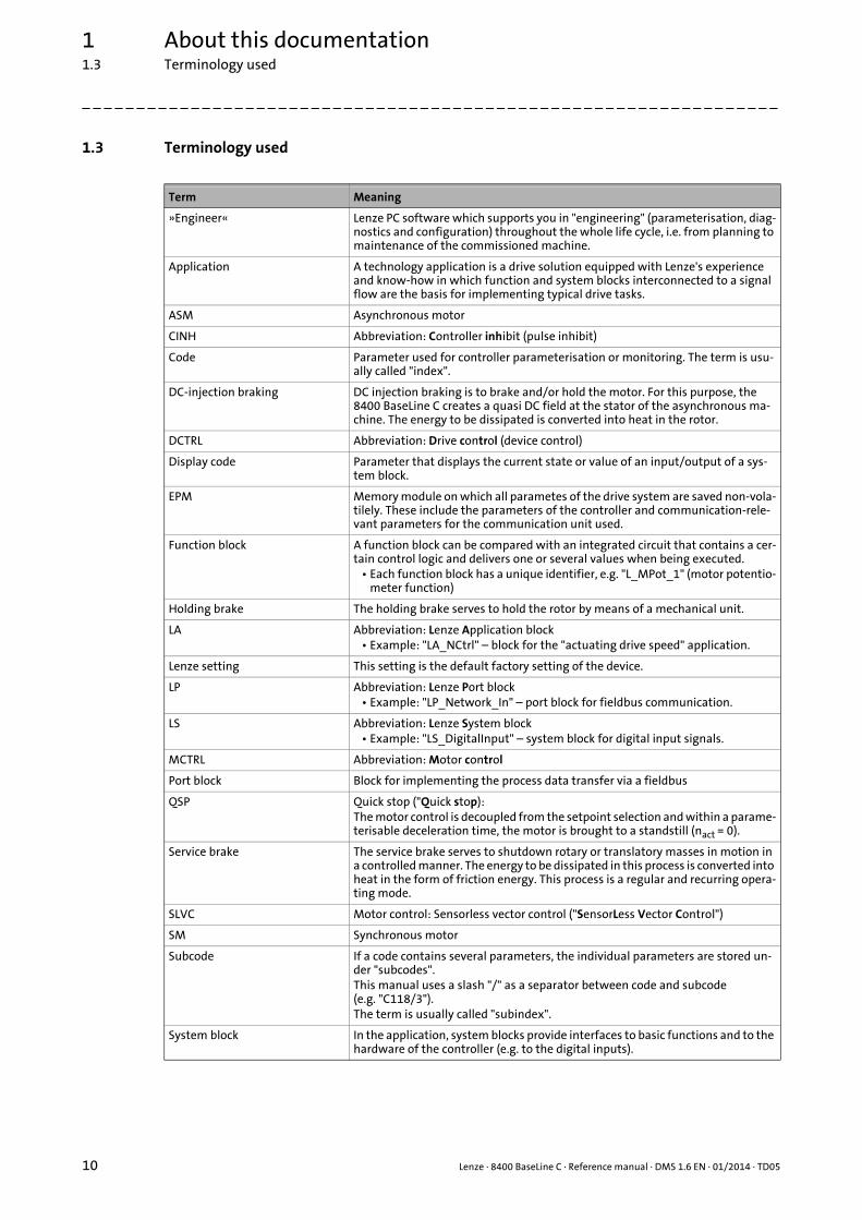
1.3 Terminology used
Term Meaning
»Engineer« Lenze PC software which supports you in "engineering" (parameterisation, diag-nostics and configuration) throughout the whole life cycle, i.e. from planning to maintenance of the commissioned machine.
Application A technology application is a drive solution equipped with Lenze's experience and know-how in which function and system blocks interconnected to a signal flow are the basis for implementing typical drive tasks.
ASM Asynchronous motor
CINH Abbreviation: Controller inhibit (pulse inhibit)
Code Parameter used for controller parameterisation or monitoring. The term is usu-ally called "index".
DC-injection braking DC injection braking is to brake and/or hold the motor. For this purpose, the 8400 BaseLine C creates a quasi DC field at the stator of the asynchronous ma-chine. The energy to be dissipated is converted into heat in the rotor.
DCTRL Abbreviation: Drive control (device control)
Display code Parameter that displays the current state or value of an input/output of a sys-tem block.
EPM Memory module on which all parametes of the drive system are saved non-vola-tilely. These include the parameters of the controller and communication-rele-vant parameters for the communication unit used.
Function block A function block can be compared with an integrated circuit that contains a cer-tain control logic and delivers one or several values when being executed.
• Each function block has a unique identifier, e.g. "L_MPot_1" (motor potentio-meter function)
Holding brake The holding brake serves to hold the rotor by means of a mechanical unit.
LA Abbreviation: Lenze Application block• Example: "LA_NCtrl" – block for the "actuating drive speed" application.
Lenze setting This setting is the default factory setting of the device.
LP Abbreviation: Lenze Port block• Example: "LP_Network_In" – port block for fieldbus communication.
LS Abbreviation: Lenze System block• Example: "LS_DigitalInput" – system block for digital input signals.
MCTRL Abbreviation: Motor control
Port block Block for implementing the process data transfer via a fieldbus
QSP Quick stop ("Quick stop):The motor control is decoupled from the setpoint selection and within a parame-terisable deceleration time, the motor is brought to a standstill (nact = 0).
Service brake The service brake serves to shutdown rotary or translatory masses in motion in a controlled manner. The energy to be dissipated in this process is converted into heat in the form of friction energy. This process is a regular and recurring opera-ting mode.
SLVC Motor control: Sensorless vector control ("SensorLess Vector Control")
SM Synchronous motor
Subcode If a code contains several parameters, the individual parameters are stored un-der "subcodes".This manual uses a slash "/" as a separator between code and subcode (e.g. "C118/3").The term is usually called "subindex".
System block In the application, system blocks provide interfaces to basic functions and to the hardware of the controller (e.g. to the digital inputs).

Lenze · 8400 BaseLine C · Reference manual · DMS 1.6 EN · 01/2014 · TD05 11
1 About this documentation1.4 Definition of the notes used
_ _ _ _ _ _ _ _ _ _ _ _ _ _ _ _ _ _ _ _ _ _ _ _ _ _ _ _ _ _ _ _ _ _ _ _ _ _ _ _ _ _ _ _ _ _ _ _ _ _ _ _ _ _ _ _ _ _ _ _ _ _ _ _
1.4 Definition of the notes used
The following signal words and symbols are used in this documentation to indicate dangers and im-portant information:
Safety instructions
Layout of the safety instructions:
Application notes
USB diagnostic adapter The USB diagnostic adapter is used for the operation, parameterisation, and di-agnostics of the controller. Data are exchanged between the PC (USB connec-tion) and the controller (diagnostic interface on the front) via the diagnostic adapter.
• Order designation: E94AZCUS
VFCplus Motor control: V/f characteristic control ("Voltage Frequency Control")
Term Meaning
Pictograph and signal word!
(characterise the type and severity of danger)
Note
(describes the danger and informs how to prevent dangerous situations)
Pictograph Signal word Meaning
Danger! Danger of personal injury through dangerous electrical voltageReference to an imminent danger that may result in death or serious personal injury if the corresponding measures are not taken.
Danger! Danger of personal injury through a general source of dangerReference to an imminent danger that may result in death or serious personal injury if the corresponding measures are not taken.
Stop! Danger of property damageReference to a possible danger that may result in property damage if the correspon-ding measures are not taken.
Pictograph Signal word Meaning
Note! Important note to ensure trouble-free operation
Tip! Useful tip for easy handling
2 Introduction: Parameterising the controller
12 Lenze · 8400 BaseLine C · Reference manual · DMS 1.6 EN · 01/2014 · TD05
_ _ _ _ _ _ _ _ _ _ _ _ _ _ _ _ _ _ _ _ _ _ _ _ _ _ _ _ _ _ _ _ _ _ _ _ _ _ _ _ _ _ _ _ _ _ _ _ _ _ _ _ _ _ _ _ _ _ _ _ _ _ _ _
2 Introduction: Parameterising the controller
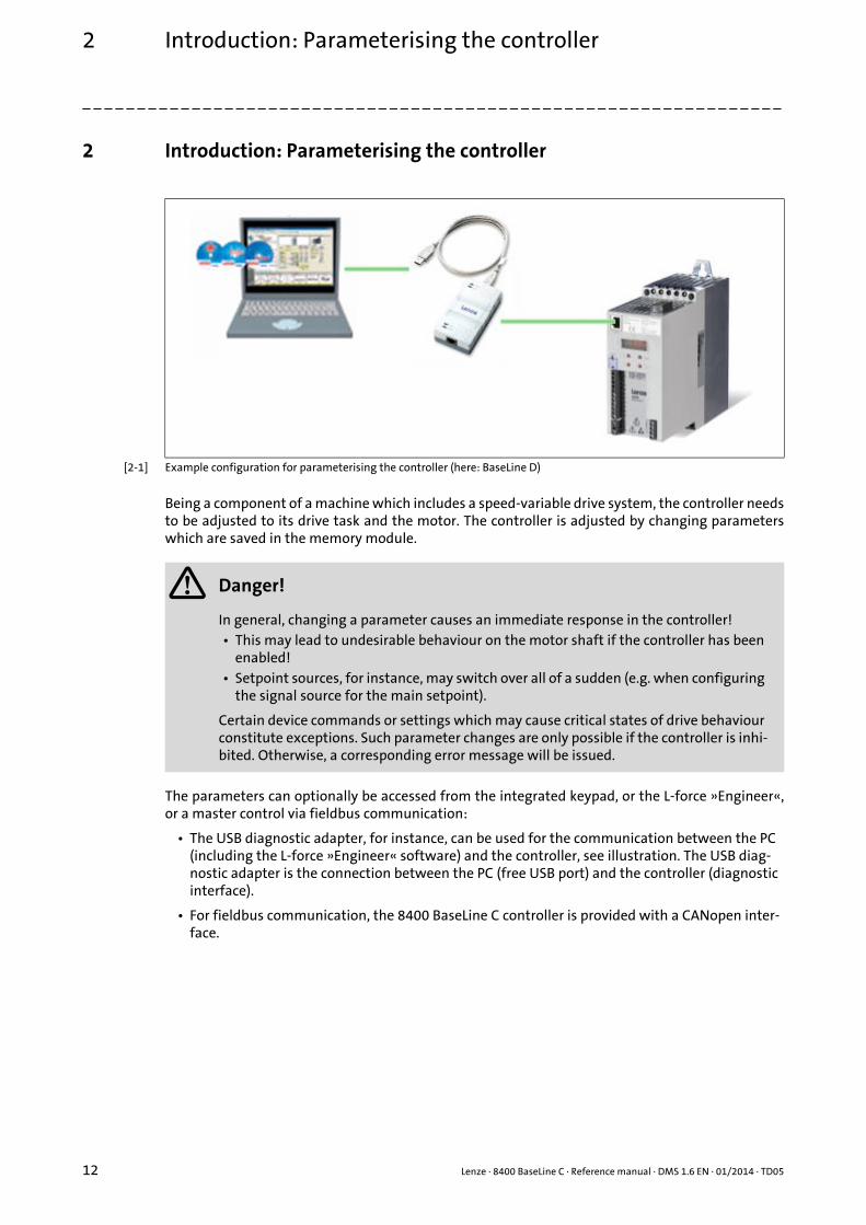
[2-1] Example configuration for parameterising the controller (here: BaseLine D)
Being a component of a machine which includes a speed-variable drive system, the controller needsto be adjusted to its drive task and the motor. The controller is adjusted by changing parameterswhich are saved in the memory module.
The parameters can optionally be accessed from the integrated keypad, or the L-force »Engineer«,or a master control via fieldbus communication:
• The USB diagnostic adapter, for instance, can be used for the communication between the PC (including the L-force »Engineer« software) and the controller, see illustration. The USB diag-nostic adapter is the connection between the PC (free USB port) and the controller (diagnostic interface).
• For fieldbus communication, the 8400 BaseLine C controller is provided with a CANopen inter-face.
Danger!
In general, changing a parameter causes an immediate response in the controller!• This may lead to undesirable behaviour on the motor shaft if the controller has been
enabled!• Setpoint sources, for instance, may switch over all of a sudden (e.g. when configuring
the signal source for the main setpoint).
Certain device commands or settings which may cause critical states of drive behaviour constitute exceptions. Such parameter changes are only possible if the controller is inhi-bited. Otherwise, a corresponding error message will be issued.

Lenze · 8400 BaseLine C · Reference manual · DMS 1.6 EN · 01/2014 · TD05 13
2 Introduction: Parameterising the controller2.1 General notes on parameters
_ _ _ _ _ _ _ _ _ _ _ _ _ _ _ _ _ _ _ _ _ _ _ _ _ _ _ _ _ _ _ _ _ _ _ _ _ _ _ _ _ _ _ _ _ _ _ _ _ _ _ _ _ _ _ _ _ _ _ _ _ _ _ _
2.1 General notes on parameters
All parameters for controller parameterising or monitoring are saved as so-called "codes".
• The codes are numbered and designated by a "C" in front of the code, e.g. "C002" in the docu-mentation and the keypad display.
• In addition, every code has a name and specific attributes:• Access type (read, write)• Data type• Limit values• Lenze setting (factory-set scaling)
• For the sake of clarity, some codes contain "subcodes" for saving parameters.• This manual uses a slash "/" as a separator between code and subcode (e.g. "C115/1").• In the keypad display, the subcodes are designated by a small "c", e.g. "c001".
• According to their functionality, the parameters are divided into three groups:
Tip!
The terms "code" and "subcode" generally correspond to the terms "index" and "subindex"and "parameter" and "subparameter".
Parameter group Examples
Setting parametersParameters for specifying setpoints and for setting device / monitoring functions.
C007: Selection of control modeC012: Acceleration time - main setpointC039: Fixed setpoints
Configuration parametersParameters for configuring signal connections within the de-vice, e.g. assignment of the digital input terminals to the control inputs of the application.
C620: System connection list: 16-bitC621: System connection list: BoolC700: LA_NCtrl: Analog connection listC701: LA_NCtrl: Digital connection list
Diagnostic/Display parametersParameters for displaying device-internal process factors, current actual values, and status messages, e.g. for diag-nostic purposes. These are read-only parameters.
C052: Motor voltageC137: Device statusC150: Status wordC165: Error info

2 Introduction: Parameterising the controller2.2 Handling the memory module
14 Lenze · 8400 BaseLine C · Reference manual · DMS 1.6 EN · 01/2014 · TD05
_ _ _ _ _ _ _ _ _ _ _ _ _ _ _ _ _ _ _ _ _ _ _ _ _ _ _ _ _ _ _ _ _ _ _ _ _ _ _ _ _ _ _ _ _ _ _ _ _ _ _ _ _ _ _ _ _ _ _ _ _ _ _ _
2.2 Handling the memory module
All parameters of the drive system are saved non-volatilely in the memory module of the controller.This includes the parameters of the controller and parameters relevant for communication.
The plug-in version is especially suited for
• restoring an application after replacing a device.
• duplicating identical drive tasks within the 8400 BaseLine frequency inverter series, e.g. by using the optionally available EPM Programmer.
When handling the memory module, a distinction is drawn between the following scenarios:
Delivery status
Danger!
After power-off, wait at least three minutes before working on the controller. When re-moving the memory module, ensure that the controller is deenergised.
If the memory module has been removed and the device is switched on, the connector pins are live and thus dangerous since the protection against contact is missing.
Note!
• When the device is switched on, all parameters are automatically loaded from the me-mory module to the main memory of the controller.
• The 8400 BaseLine and 8400 motec controllers use the same (grey) memory module. The memory module can be shifted between these controllers but the controller must be reparameterised afterwards.
• The memory module is not compatible with the memory modules of the 8400 StateLine and 8400 HighLine controllers.
• If the memory module has been removed, the "PS01" error message appears.
• The memory module is plugged into the EPM slot at the front of the controller.
• The Lenze setting of the parameters is stored in the memo-ry module.
• The memory module can be preconfigured with customer-specific data.
• The memory module is available as a spare part - without any data.

Lenze · 8400 BaseLine C · Reference manual · DMS 1.6 EN · 01/2014 · TD05 15
2 Introduction: Parameterising the controller2.2 Handling the memory module
_ _ _ _ _ _ _ _ _ _ _ _ _ _ _ _ _ _ _ _ _ _ _ _ _ _ _ _ _ _ _ _ _ _ _ _ _ _ _ _ _ _ _ _ _ _ _ _ _ _ _ _ _ _ _ _ _ _ _ _ _ _ _ _
During operation
• The memory module (EPM) is required for operation.
• Full functionality of the memory module is even provided if the power supply has been switched off and only the electronic components of the controller are externally supplied by a 24 V DC vol-tage, e.g. via the X4/24E terminal.
• Parameter settings can be saved manually.
• Parameter settings can be loaded manually.
• Parameter changes can be saved automatically.
Replacing the controller
• In the event of a device replacement, the entire parameter data of an axis can be copied to the replacement device by "taking along" the memory module, so that additional PC or diagnosis terminal operations are not required.
• When replacing the controller, the versions of the old device and the new device are of impor-tance. Before data are actually transferred, the versions are internally checked. Basically, the fol-lowing applies:• Parameter sets of old devices with V 1.0 can be processed on new devices ≥ V 1.0
(downward compatibility).• Parameters of devices with higher versions are not supported on devices with lower versions.
An error message (PS02/PS03) occurs if the parameter set versions of the two devices are not compatible.
Saving the parameters in the memory module safe against mains failure
Controller parameter changes via the »Engineer«, the integrated keypad, or a master control viafieldbus communication will be lost after mains switching of the controller unless the settings havebeen explicitly saved.
You have various opportunities to prevent a data loss by saving the parameter settings in the me-mory module:
• Quick saving of all parameters at the push of a button ( 23)
• Automatic saving of parameter changes ( 49)
• Manual saving of parameter settings ( 49)
Stop!
The memory module must not be plugged in or unplugged during operation.
2 Introduction: Parameterising the controller2.2 Handling the memory module
16 Lenze · 8400 BaseLine C · Reference manual · DMS 1.6 EN · 01/2014 · TD05
_ _ _ _ _ _ _ _ _ _ _ _ _ _ _ _ _ _ _ _ _ _ _ _ _ _ _ _ _ _ _ _ _ _ _ _ _ _ _ _ _ _ _ _ _ _ _ _ _ _ _ _ _ _ _ _ _ _ _ _ _ _ _ _
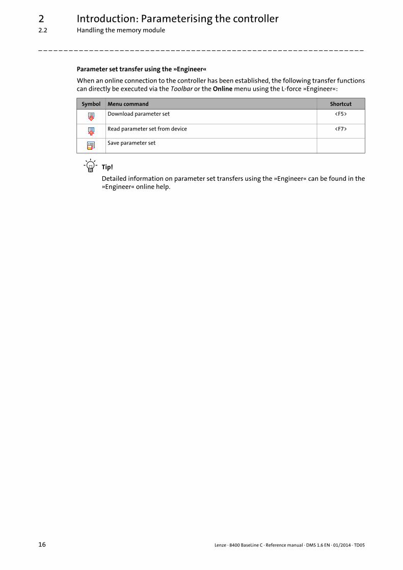
Parameter set transfer using the »Engineer«
When an online connection to the controller has been established, the following transfer functionscan directly be executed via the Toolbar or the Online menu using the L-force »Engineer«:
Tip!
Detailed information on parameter set transfers using the »Engineer« can be found in the»Engineer« online help.
Symbol Menu command Shortcut
Download parameter set <F5>
Read parameter set from device <F7>
Save parameter set
Lenze · 8400 BaseLine C · Reference manual · DMS 1.6 EN · 01/2014 · TD05 17
2 Introduction: Parameterising the controller2.3 Internal Keypad
_ _ _ _ _ _ _ _ _ _ _ _ _ _ _ _ _ _ _ _ _ _ _ _ _ _ _ _ _ _ _ _ _ _ _ _ _ _ _ _ _ _ _ _ _ _ _ _ _ _ _ _ _ _ _ _ _ _ _ _ _ _ _ _
2.3 Internal Keypad
The controller front is provided with an integrated keypad. Use the keypad for quick and simple pa-rameter setting and for displaying current actual values and device states via the respective displayparameters.
2.3.1 Display elements and control panel
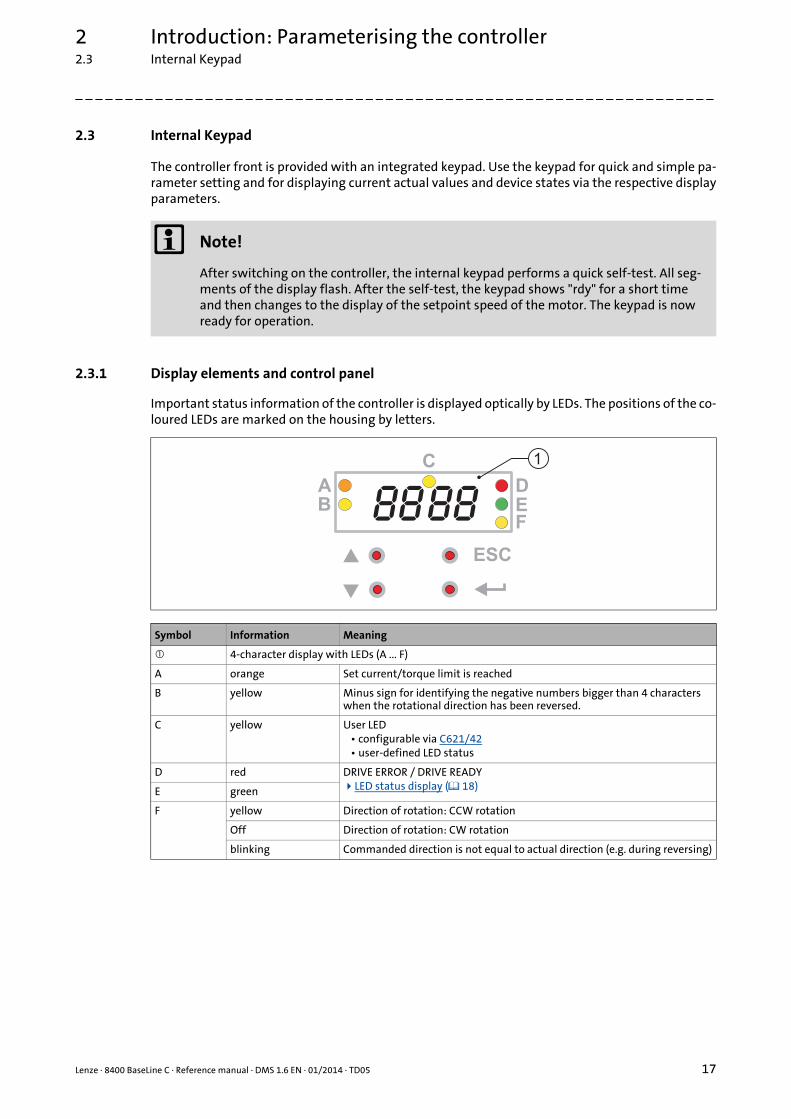
Important status information of the controller is displayed optically by LEDs. The positions of the co-loured LEDs are marked on the housing by letters.
Note!
After switching on the controller, the internal keypad performs a quick self-test. All seg-ments of the display flash. After the self-test, the keypad shows "rdy" for a short time and then changes to the display of the setpoint speed of the motor. The keypad is now ready for operation.
Symbol Information Meaning
4-character display with LEDs (A ... F)
A orange Set current/torque limit is reached
B yellow Minus sign for identifying the negative numbers bigger than 4 characters when the rotational direction has been reversed.
C yellow User LED• configurable via C621/42• user-defined LED status
D red DRIVE ERROR / DRIVE READYLED status display ( 18) E green
F yellow Direction of rotation: CCW rotation
Off Direction of rotation: CW rotation
blinking Commanded direction is not equal to actual direction (e.g. during reversing)
8888B
ESC
C
DEF
A
1
2 Introduction: Parameterising the controller2.3 Internal Keypad
18 Lenze · 8400 BaseLine C · Reference manual · DMS 1.6 EN · 01/2014 · TD05
_ _ _ _ _ _ _ _ _ _ _ _ _ _ _ _ _ _ _ _ _ _ _ _ _ _ _ _ _ _ _ _ _ _ _ _ _ _ _ _ _ _ _ _ _ _ _ _ _ _ _ _ _ _ _ _ _ _ _ _ _ _ _ _
Control elements
2.3.2 LED status display
Key Name Function
ESC Escape key On menu and parameter level: BackIn case of parameter processing: Abort (discard changed setting)
↵ Enter key On menu and parameter level: Next (confirm selection)In case of parameter processing: OK (accept changed setting)Long pressing (3 seconds): Saving of all parametersQuick saving of all parameters at the push of a button ( 23)
Navigation keyupwards
On menu and parameter level: NavigationIn case of parameter processing: Set parameter valueLong pressing (> 2 seconds): Quick scroll function Navigation key
downwards
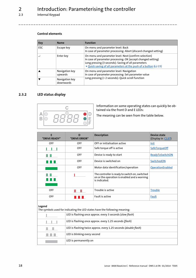
Information on some operating states can quickly be ob-tained via the front D and E LEDs:
The meaning can be seen from the table below.
E"DRIVE READY"
D"DRIVE ERROR"
Description Device state(Display in C137)
OFF OFF OFF or initialisation active Init
OFF Safe torque off is active SafeTorqueOff
OFF Device is ready to start ReadyToSwitchON
OFF Device is switched on SwitchedON
OFF Motor data identification/operation OperationEnabled
The controller is ready to switch on, switched on or the operation is enabled and a warning is indicated.
OFF Trouble is active Trouble
OFF Fault is active Fault
LegendThe symbols used for indicating the LED states have the following meaning:
LED is flashing once approx. every 3 seconds (slow flash)
LED is flashing once approx. every 1.25 seconds (flash)
LED is flashing twice approx. every 1.25 seconds (double flash)
LED is blinking every second
LED is permanently on
8888B
C
D
EF
A
Lenze · 8400 BaseLine C · Reference manual · DMS 1.6 EN · 01/2014 · TD05 19
2 Introduction: Parameterising the controller2.3 Internal Keypad
_ _ _ _ _ _ _ _ _ _ _ _ _ _ _ _ _ _ _ _ _ _ _ _ _ _ _ _ _ _ _ _ _ _ _ _ _ _ _ _ _ _ _ _ _ _ _ _ _ _ _ _ _ _ _ _ _ _ _ _ _ _ _ _
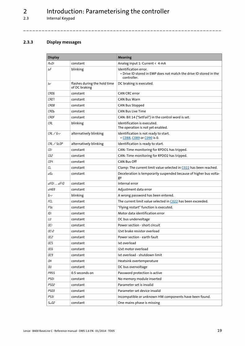
2.3.3 Display messages
Display Meaning
An01 constant Analog input 1: Current < 4 mA
bF blinking Identification error.• Drive ID stored in EMP does not match the drive ID stored in the
controller.
br flashes during the hold time of DC braking
DC braking is executed.
CA06 constant CAN CRC error
CA07 constant CAN Bus Warn
CA08 constant CAN Bus Stopped
CA0b constant CAN Bus Live Time
CA0F constant CAN: Bit 14 ("SetFail") in the control word is set.
CAL blinking Identification is executed.The operation is not yet enabled.
CAL / Err alternatively blinking Identification is not ready to start.• C088, C089 or C090 is 0.
CAL / Stop alternatively blinking Identification is ready to start.
CE1 constant CAN: Time monitoring for RPDO1 has tripped.
CE2 constant CAN: Time monitoring for RPDO2 has tripped.
CE4 constant CAN Bus Off
CL constant Clamp: The current limit value selected in C022 has been reached.
dec constant Deceleration is temporarily suspended because of higher bus volta-ge
dF01 ... dF10 constant Internal error
dH69 constant Adjustment data error
Err blinking A wrong password has been entered.
FCL constant The current limit value selected in C022 has been exceeded.
FSt constant "Flying restart" function is executed.
ID1 constant Motor data identification error
LU constant DC bus undervoltage
OC1 constant Power section - short circuit
OC12 constant I2xt brake resistor overload
OC2 constant Power section - earth fault
OC5 constant Ixt overload
OC6 constant I2xt motor overload
OC9 constant Ixt overload - shutdown limit
OH constant Heatsink overtemperature
OU constant DC bus overvoltage
PASS 0.5 seconds on Password protection is active
PS01 constant No memory module inserted
PS02 constant Parameter set is invalid
PS03 constant Parameter set device invalid
PS31 constant Incompatible or unknown HW components have been found.
Su02 constant One mains phase is missing

2 Introduction: Parameterising the controller2.3 Internal Keypad
20 Lenze · 8400 BaseLine C · Reference manual · DMS 1.6 EN · 01/2014 · TD05
_ _ _ _ _ _ _ _ _ _ _ _ _ _ _ _ _ _ _ _ _ _ _ _ _ _ _ _ _ _ _ _ _ _ _ _ _ _ _ _ _ _ _ _ _ _ _ _ _ _ _ _ _ _ _ _ _ _ _ _ _ _ _ _
US01 constant User error 1
US02 constant User error 2
Detailed information on diagnostics using the »Engineer« and a description of possible error messages can be found in the chapter entitled "Diagnostics & error management". ( 145)
Display Meaning
Lenze · 8400 BaseLine C · Reference manual · DMS 1.6 EN · 01/2014 · TD05 21
2 Introduction: Parameterising the controller2.3 Internal Keypad
_ _ _ _ _ _ _ _ _ _ _ _ _ _ _ _ _ _ _ _ _ _ _ _ _ _ _ _ _ _ _ _ _ _ _ _ _ _ _ _ _ _ _ _ _ _ _ _ _ _ _ _ _ _ _ _ _ _ _ _ _ _ _ _
2.3.4 Menu structure
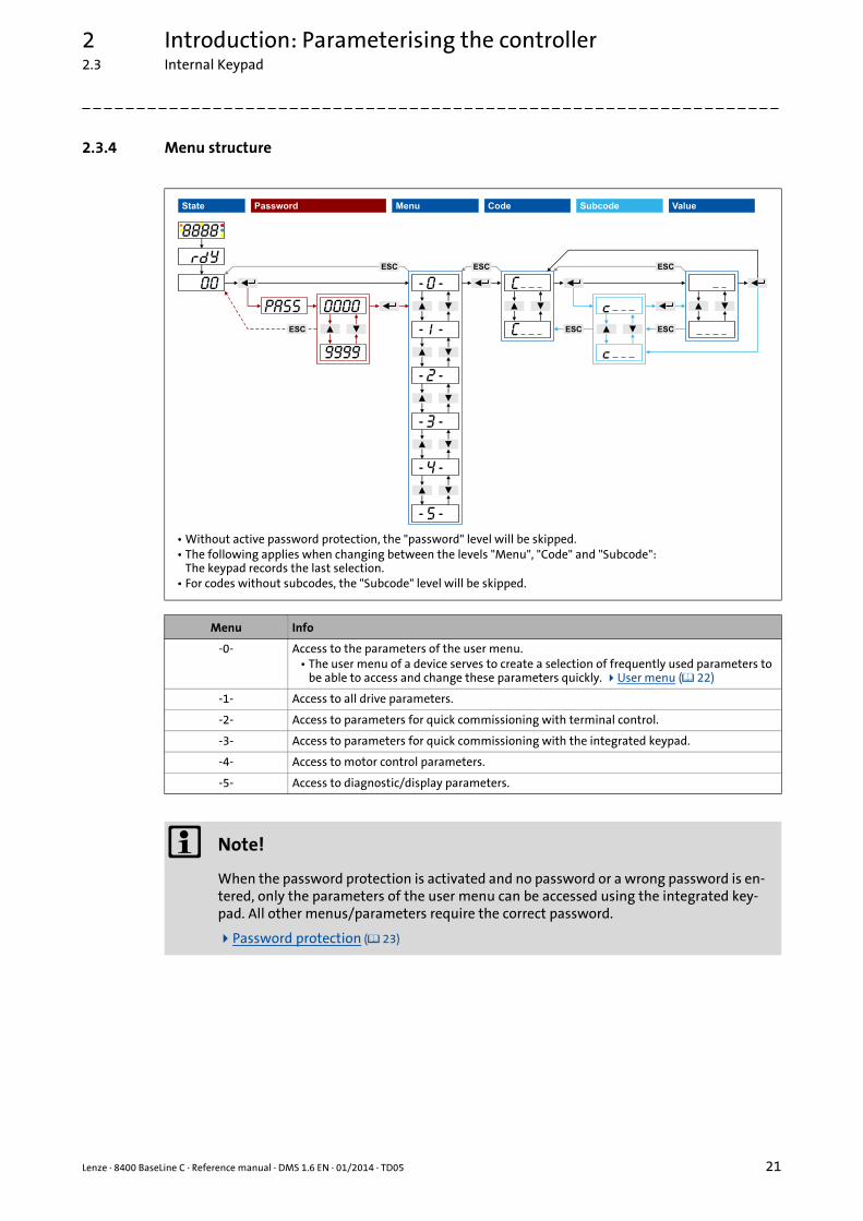
• Without active password protection, the "password" level will be skipped.• The following applies when changing between the levels "Menu", "Code" and "Subcode":
The keypad records the last selection.• For codes without subcodes, the "Subcode" level will be skipped.
Menu Info
-0- Access to the parameters of the user menu.• The user menu of a device serves to create a selection of frequently used parameters to
be able to access and change these parameters quickly. User menu ( 22)
-1- Access to all drive parameters.
-2- Access to parameters for quick commissioning with terminal control.
-3- Access to parameters for quick commissioning with the integrated keypad.
-4- Access to motor control parameters.
-5- Access to diagnostic/display parameters.
Note!
When the password protection is activated and no password or a wrong password is en-tered, only the parameters of the user menu can be accessed using the integrated key-pad. All other menus/parameters require the correct password.
Password protection ( 23)

2 Introduction: Parameterising the controller2.3 Internal Keypad
22 Lenze · 8400 BaseLine C · Reference manual · DMS 1.6 EN · 01/2014 · TD05
_ _ _ _ _ _ _ _ _ _ _ _ _ _ _ _ _ _ _ _ _ _ _ _ _ _ _ _ _ _ _ _ _ _ _ _ _ _ _ _ _ _ _ _ _ _ _ _ _ _ _ _ _ _ _ _ _ _ _ _ _ _ _ _
2.3.5 User menu
The user menu (menu -0-) contains a selection of frequently used parameters to be able to accessand change these parameters quickly.
• The integrated keypad serves to change the preset parameter selection in C517: Enter the codes the user menu is to contain into the subcodes c001 ...c020. When "0" is set, no entry is displayed in the user menu.
• The »Engineer« serves to configure the user menu on the User menu tab of the controller. Here, additional functions are available for loading and saving the parameter selection.
The user menu contains the following parameters:
Code Subcode Info Lenze setting
Value Unit
C051 - Display of actual speed value - rpm
C053 - Display of DC-bus voltage - V
C054 - Display of motor current - A
C061 - Display of heatsink temperature - °C
C137 - Display of device status -
C011 - Reference speed 1500 rpm
C039 c001 Fixed setpoint 1 40.0 %
c002 Fixed setpoint 2 60.0 %
c003 Fixed setpoint 3 80.0 %
C012 - Acceleration time - main setpoint 2.0 s
C013 - Deceleration time - main setpoint 2.0 s
C015 - V/f base frequency 50.0 Hz
C016 - Vmin boost 0.0 %
C022 - Imax in motor mode 47.00 A
C120 - Motor overload threshold (I2xt) 100 %
C087 - Rated motor speed 1460 rpm
C099 - Display of firmware version -
Highlighted in grey = display parameter
Note!
If the password protection is activated and no password or a wrong password is entered, only these parameters can be accessed with the integrated keypad.
Password protection ( 23)

Lenze · 8400 BaseLine C · Reference manual · DMS 1.6 EN · 01/2014 · TD05 23
2 Introduction: Parameterising the controller2.3 Internal Keypad
_ _ _ _ _ _ _ _ _ _ _ _ _ _ _ _ _ _ _ _ _ _ _ _ _ _ _ _ _ _ _ _ _ _ _ _ _ _ _ _ _ _ _ _ _ _ _ _ _ _ _ _ _ _ _ _ _ _ _ _ _ _ _ _
2.3.6 Quick saving of all parameters at the push of a button
Keep the entry button pressed for 3 seconds to save all parameter settings safe against mains failu-re.
Related topics:
Save parameter settings ( 49)
2.3.7 Password protection
The controller offers the option to protect the unauthorised access to the menu level by assigning apassword. The following sections describe how to create, change, or delete the password protectionand how to access the menu level via the password.
Enter password and confirm it
Carry out the steps if you want to create the password protection for the first time for e.g. a control-ler in default status:
• During the saving process, "SAVE" is blinking in the display.
• After approximately 2 seconds, "SAVE" will disappear from the display and you can continue your work.B
ESC
C
DEF
A
8888
3 sec
SAVE
Step Info
1. Mains on After the mains has been switched on and the keypad self test has been completed, "00" is displayed
2. ↵ After pressing the enter key:Without password protection you have free access from here to all menus (and thus all parameters).
3. Select menu -1- (all parameters).
4. ↵ Confirm selection.
5. Select code C094 ("password").
6. ↵ Confirm selection.("00" is now blinking, i.e. entry is possible.)
7. Set the desired password ("01" ... "9999").
8. ↵ Accept password.
9. ↵ (3 seconds) Keep the entry button pressed for 3 seconds in order to save the parameter settings safe against mains failure.
2 Introduction: Parameterising the controller2.3 Internal Keypad
24 Lenze · 8400 BaseLine C · Reference manual · DMS 1.6 EN · 01/2014 · TD05
_ _ _ _ _ _ _ _ _ _ _ _ _ _ _ _ _ _ _ _ _ _ _ _ _ _ _ _ _ _ _ _ _ _ _ _ _ _ _ _ _ _ _ _ _ _ _ _ _ _ _ _ _ _ _ _ _ _ _ _ _ _ _ _
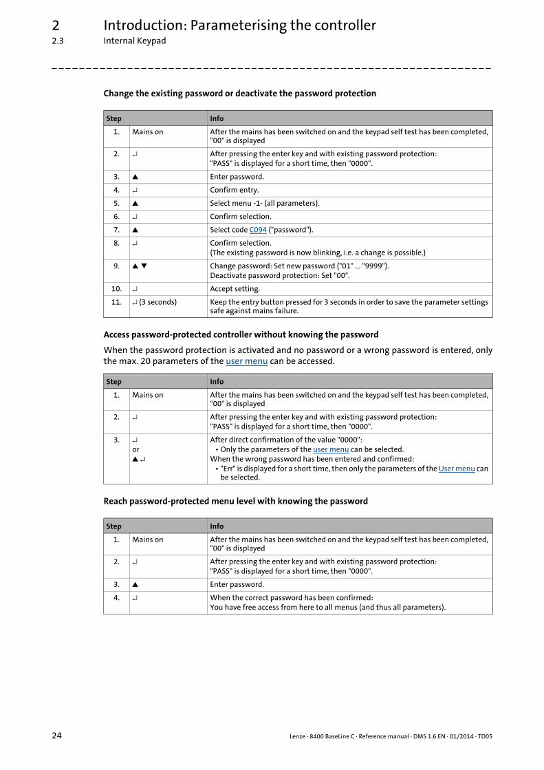
Change the existing password or deactivate the password protection
Access password-protected controller without knowing the password
When the password protection is activated and no password or a wrong password is entered, onlythe max. 20 parameters of the user menu can be accessed.
Reach password-protected menu level with knowing the password
Step Info
1. Mains on After the mains has been switched on and the keypad self test has been completed, "00" is displayed
2. ↵ After pressing the enter key and with existing password protection:"PASS" is displayed for a short time, then "0000".
3. Enter password.
4. ↵ Confirm entry.
5. Select menu -1- (all parameters).
6. ↵ Confirm selection.
7. Select code C094 ("password").
8. ↵ Confirm selection.(The existing password is now blinking, i.e. a change is possible.)
9. Change password: Set new password ("01" ... "9999").Deactivate password protection: Set "00".
10. ↵ Accept setting.
11. ↵ (3 seconds) Keep the entry button pressed for 3 seconds in order to save the parameter settings safe against mains failure.
Step Info
1. Mains on After the mains has been switched on and the keypad self test has been completed, "00" is displayed
2. ↵ After pressing the enter key and with existing password protection:"PASS" is displayed for a short time, then "0000".
3. ↵or ↵
After direct confirmation of the value "0000":• Only the parameters of the user menu can be selected.
When the wrong password has been entered and confirmed:• "Err" is displayed for a short time, then only the parameters of the User menu can
be selected.
Step Info
1. Mains on After the mains has been switched on and the keypad self test has been completed, "00" is displayed
2. ↵ After pressing the enter key and with existing password protection:"PASS" is displayed for a short time, then "0000".
3. Enter password.
4. ↵ When the correct password has been confirmed:You have free access from here to all menus (and thus all parameters).

Lenze · 8400 BaseLine C · Reference manual · DMS 1.6 EN · 01/2014 · TD05 25
3 Commissioning3.1 Safety instructions with regard to commissioning
_ _ _ _ _ _ _ _ _ _ _ _ _ _ _ _ _ _ _ _ _ _ _ _ _ _ _ _ _ _ _ _ _ _ _ _ _ _ _ _ _ _ _ _ _ _ _ _ _ _ _ _ _ _ _ _ _ _ _ _ _ _ _ _
3 Commissioning
The 8400 BaseLine C controller is commissioned in one of the following ways:
• Commissioning with integrated keypad• If only a few parameters have to be adapted.• For test/demonstration purposes.
• Commissioning with PC/»Engineer«• The »Engineer« provides a comfortable access to all parameters of the 8400 BaseLine C con-
troller and hence full flexibility in the commissioning process.
3.1 Safety instructions with regard to commissioning
General safety instructions
In order to prevent injury to persons or damage to material assets
• before connecting the mains voltage, check• The wiring for completeness, short circuit, and earth fault• The "emergency stop" function of the entire system• The motor circuit configuration (star/delta) must be adapted to the output voltage of the
controller• The in-phase connection of the motor
• Check the setting of the most important drive parameters before enabling the controller:• The V/f rated frequency must be adapted to the motor circuit configuration!• The drive parameters relevant for your application must be set correctly!• The configuration of the I/O terminals must be adapted to the wiring!
• Make sure that no speed setpoint is applied before controller enable.
Safety instructions with regard to motor operation
Danger!
• For thermal reasons, continuous operation of self-ventilated motors at a low field fre-quency and rated motor current is not permissible!• If required, activate the Brake resistor monitoring (I2xt). ( 106)
• With regard to the V/f base frequency (C015), observe the following difference to the controllers 8400 StateLine/HighLine/TopLine:For the 8400 BaseLine, the reference voltage for the V/f base frequency is the rated motor voltage (C090) according to motor nameplate (independent of the mains vol-tage on the supply side).
3 Commissioning3.2 Preparing the 8400 BaseLine for commissioning
26 Lenze · 8400 BaseLine C · Reference manual · DMS 1.6 EN · 01/2014 · TD05
_ _ _ _ _ _ _ _ _ _ _ _ _ _ _ _ _ _ _ _ _ _ _ _ _ _ _ _ _ _ _ _ _ _ _ _ _ _ _ _ _ _ _ _ _ _ _ _ _ _ _ _ _ _ _ _ _ _ _ _ _ _ _ _
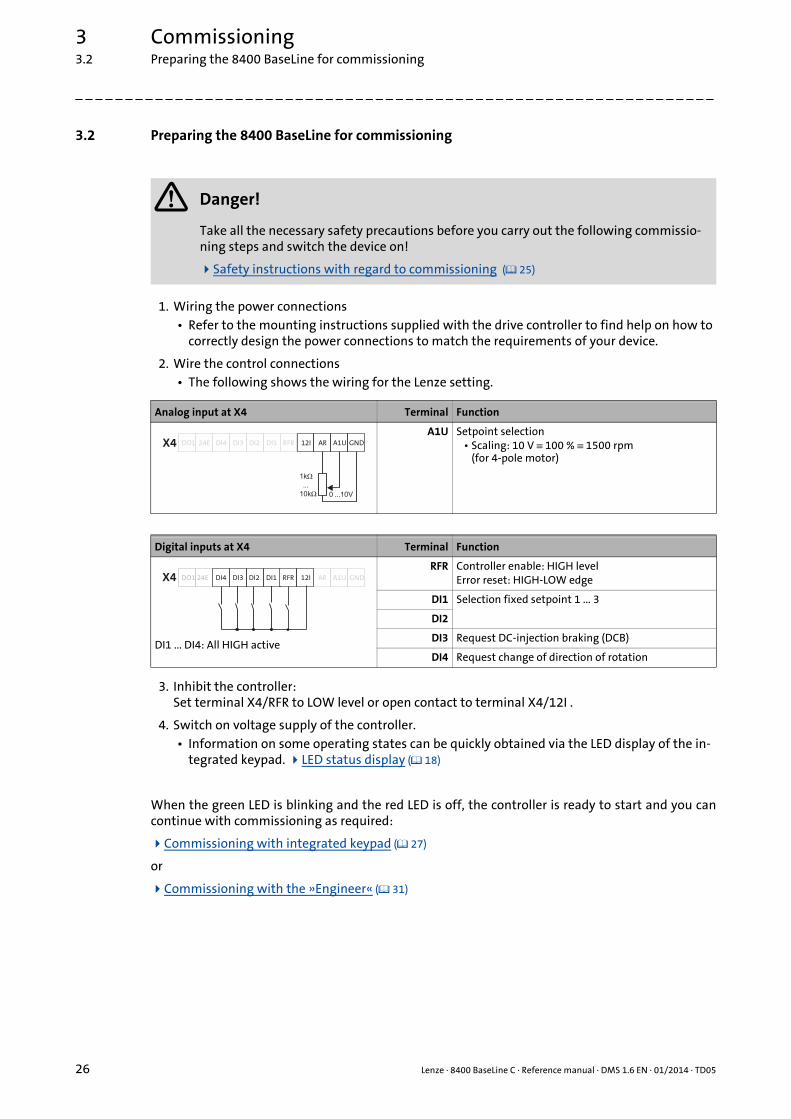
3.2 Preparing the 8400 BaseLine for commissioning
1. Wiring the power connections• Refer to the mounting instructions supplied with the drive controller to find help on how to
correctly design the power connections to match the requirements of your device.
2. Wire the control connections• The following shows the wiring for the Lenze setting.
3. Inhibit the controller:Set terminal X4/RFR to LOW level or open contact to terminal X4/12I .
4. Switch on voltage supply of the controller.• Information on some operating states can be quickly obtained via the LED display of the in-
tegrated keypad. LED status display ( 18)
When the green LED is blinking and the red LED is off, the controller is ready to start and you cancontinue with commissioning as required:
Commissioning with integrated keypad ( 27)
or
Commissioning with the »Engineer« ( 31)
Danger!
Take all the necessary safety precautions before you carry out the following commissio-ning steps and switch the device on!
Safety instructions with regard to commissioning ( 25)
Analog input at X4 Terminal Function
A1U Setpoint selection• Scaling: 10 V ≡ 100 % ≡ 1500 rpm
(for 4-pole motor)
Digital inputs at X4 Terminal Function
DI1 ... DI4: All HIGH active
RFR Controller enable: HIGH levelError reset: HIGH-LOW edge
DI1 Selection fixed setpoint 1 ... 3
DI2
DI3 Request DC-injection braking (DCB)
DI4 Request change of direction of rotation
DI1DI2DI3DI4 RFRX4 24EDO1 12I AR A1U GND
0 10V���
1k
10k
�
���
�
AR A1U GNDDI1DI2DI3 RFRX4 DO1 12I24E DI4

Lenze · 8400 BaseLine C · Reference manual · DMS 1.6 EN · 01/2014 · TD05 27
3 Commissioning3.3 Commissioning with integrated keypad
_ _ _ _ _ _ _ _ _ _ _ _ _ _ _ _ _ _ _ _ _ _ _ _ _ _ _ _ _ _ _ _ _ _ _ _ _ _ _ _ _ _ _ _ _ _ _ _ _ _ _ _ _ _ _ _ _ _ _ _ _ _ _ _
3.3 Commissioning with integrated keypad
Only a few parameters need to be adapted for the drive. Afterwards, the drive application can be im-mediately controlled via the digital and analog inputs of the controller in the preset control mode"Terminals 0".
Commissioning steps
In the following, commissioning of the controller using the integrated keypad is described step bystep. Please process the chapters consecutively and execute all steps carefully. This procedure willhelp you to commission the controller quickly and as safe as possible:
Load Lenze setting
Parameterise drive/application ( 28)
Save parameter settings safe against mains failure ( 29)
Enable controller and select speed ( 30)
3.3.1 Load Lenze setting
In order to achieve a defined device configuration, it is advisable to make sure that the device is inits original delivery state. For this purpose, the "Load Lenze setting" device command is available.
Information on how to use the integrated keypad can be found in the chapter entitled "Internal Keypad". ( 17)
Step Info
1. Mains on After the mains has been switched on and the keypad self test has been completed, "00" is displayed
2. ↵ After pressing the enter key:Without password protection you have free access from here to all menus (and thus all parameters).
3. Select menu -2-.• The menu -2- contains parameters for quick commissioning with terminal cont-
rol.
4. ↵ Confirm selection.
5. ↵ Confirm first code C002 ("device commands") of the menu -2-.
6. ↵ Confirm subcode c001 ("load Lenze setting").
7. Set value "01" (≡ "Start").
8. ↵ Accept parameter setting to execute the "Load Lenze setting" device command.

3 Commissioning3.3 Commissioning with integrated keypad
28 Lenze · 8400 BaseLine C · Reference manual · DMS 1.6 EN · 01/2014 · TD05
_ _ _ _ _ _ _ _ _ _ _ _ _ _ _ _ _ _ _ _ _ _ _ _ _ _ _ _ _ _ _ _ _ _ _ _ _ _ _ _ _ _ _ _ _ _ _ _ _ _ _ _ _ _ _ _ _ _ _ _ _ _ _ _
3.3.2 Parameterise drive/application
The menu -2- of the integrated keypad contains all basic parameters to commission the drive/appli-cation "actuating drive speed" quickly and easily for a terminal control. When you set these parame-ters to suitable and sensible values, the controller can be operated properly.
More detailed information on the drive application:
Drive application ( 121)
Interface description ( 127)
Setting parameters (short overview) ( 132)
Pre-assignment of the drive application ( 133)
Terminal assignment of the control modes ( 139)
Parameter Lenze setting Info
Value Unit
C002/1Load Lenze setting
0: Off / ready Reset all parameters to the Lenze setting which are sa-ved in the controller firmware.
C007Select control mode
10: Terminals 0 Terminal assignment of the control modes ( 139)
C011Reference speed
1500 rpm All speed setpoint selections are provided in % and al-ways refer to the reference speed set in C011.The motor reference speed is given on the motor name-plate.
C012Acceleration time - main setpoint
2.0 s The setpoint is led via a ramp function generator with li-near characteristic. The ramp function generator con-verts setpoint step-changes at the input into a ramp.L_NSet_1 ( 309) C013
Deceleration time - main setpoint2.0 s
C015V/f base frequency
50.0 Hz Adapting the V/f base frequency ( 83)
C016Vmin boost
0.0 % Adapting the Vmin boost ( 84)
C022Current limit (in motor mode)
47.00 A Optimising the Imax controller ( 85)
C087Rated motor speed
1460 rpm Motor selection/Motor data ( 65)
C089Rated motor frequency
50 Hz
C039/1Fixed setpoint 1
40.0 % A fixed setpoint for the setpoint generator can be acti-vated instead of the main setpoint via the digital inputs DI1 and DI2.
• The fixed setpoints are selected in [%] based on the reference speed (C011).
L_NSet_1 ( 309)
C039/2Fixed setpoint 2
60.0 %
C039/3Fixed setpoint 3
80.0 %
C051Actual speed value
- rpm
C054Current motor current
- A
Highlighted in grey = display parameter

Lenze · 8400 BaseLine C · Reference manual · DMS 1.6 EN · 01/2014 · TD05 29
3 Commissioning3.3 Commissioning with integrated keypad
_ _ _ _ _ _ _ _ _ _ _ _ _ _ _ _ _ _ _ _ _ _ _ _ _ _ _ _ _ _ _ _ _ _ _ _ _ _ _ _ _ _ _ _ _ _ _ _ _ _ _ _ _ _ _ _ _ _ _ _ _ _ _ _
3.3.3 Save parameter settings safe against mains failure
If parameter settings are changed in the controller, those changes will be lost after mains switchingof the controller unless the settings have been saved explicitly.
• Keep the entry button pressed for 3 seconds in order to save the parameter settings safe against mains failure.
Tip!
In C141, an automatic saving can be activated.Automatic saving of parameter changes ( 49)
B
ESC
C
DEF
A
8888
3 sec
SAVE
3 Commissioning3.3 Commissioning with integrated keypad
30 Lenze · 8400 BaseLine C · Reference manual · DMS 1.6 EN · 01/2014 · TD05
_ _ _ _ _ _ _ _ _ _ _ _ _ _ _ _ _ _ _ _ _ _ _ _ _ _ _ _ _ _ _ _ _ _ _ _ _ _ _ _ _ _ _ _ _ _ _ _ _ _ _ _ _ _ _ _ _ _ _ _ _ _ _ _
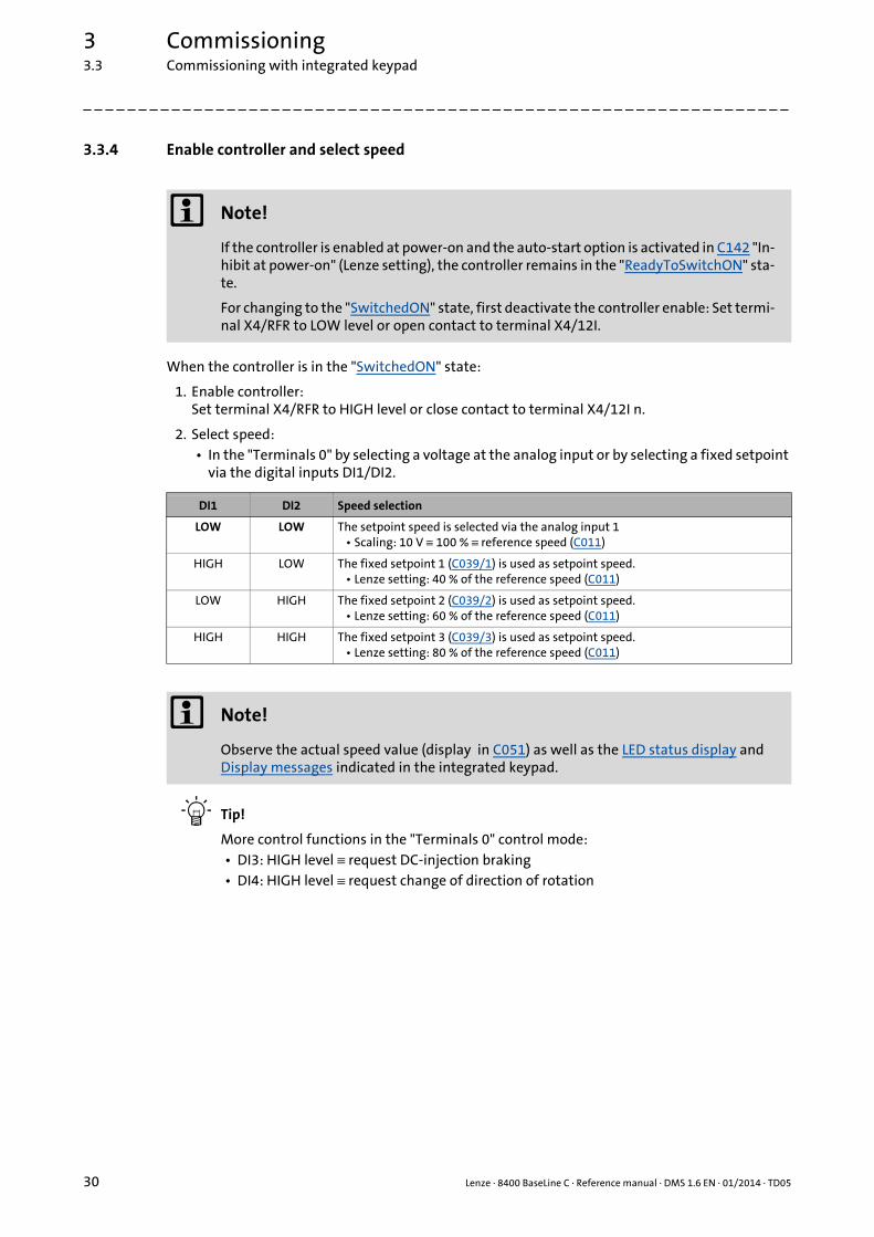
3.3.4 Enable controller and select speed
When the controller is in the "SwitchedON" state:
1. Enable controller:Set terminal X4/RFR to HIGH level or close contact to terminal X4/12I n.
2. Select speed:• In the "Terminals 0" by selecting a voltage at the analog input or by selecting a fixed setpoint
via the digital inputs DI1/DI2.
Tip!
More control functions in the "Terminals 0" control mode:• DI3: HIGH level ≡ request DC-injection braking• DI4: HIGH level ≡ request change of direction of rotation
Note!
If the controller is enabled at power-on and the auto-start option is activated in C142 "In-hibit at power-on" (Lenze setting), the controller remains in the "ReadyToSwitchON" sta-te.
For changing to the "SwitchedON" state, first deactivate the controller enable: Set termi-nal X4/RFR to LOW level or open contact to terminal X4/12I.
DI1 DI2 Speed selection
LOW LOW The setpoint speed is selected via the analog input 1• Scaling: 10 V ≡ 100 % ≡ reference speed (C011)
HIGH LOW The fixed setpoint 1 (C039/1) is used as setpoint speed.• Lenze setting: 40 % of the reference speed (C011)
LOW HIGH The fixed setpoint 2 (C039/2) is used as setpoint speed.• Lenze setting: 60 % of the reference speed (C011)
HIGH HIGH The fixed setpoint 3 (C039/3) is used as setpoint speed.• Lenze setting: 80 % of the reference speed (C011)
Note!
Observe the actual speed value (display in C051) as well as the LED status display and Display messages indicated in the integrated keypad.

Lenze · 8400 BaseLine C · Reference manual · DMS 1.6 EN · 01/2014 · TD05 31
3 Commissioning3.4 Commissioning with the »Engineer«
_ _ _ _ _ _ _ _ _ _ _ _ _ _ _ _ _ _ _ _ _ _ _ _ _ _ _ _ _ _ _ _ _ _ _ _ _ _ _ _ _ _ _ _ _ _ _ _ _ _ _ _ _ _ _ _ _ _ _ _ _ _ _ _
3.4 Commissioning with the »Engineer«
Commissioning with the »Engineer« is suited for every drive task and in particular for drive taskswith more demanding requirements/more comprehensive parameter setting.
In the following, commissioning of the controller is described step by step. Please process the chap-ters consecutively and execute all steps carefully. This procedure will help you to commission thecontroller quickly and as safe as possible:
Preconditions for commissioning with the »Engineer«
Creating an »Engineer« project & going online
Parameterise drive/application
Save parameter settings safe against mains failure
Enable controller and select speed
3.4.1 Preconditions for commissioning with the »Engineer«
For commissioning, you need
• a PC that satisfies the following requirements:• processor with 1.4 GHz or higher• at least 512 MB RAM and 650 MB free hard disc space• Microsoft® Windows® 2000 operating system (from service pack 2 onwards) or
Windows® XP
• the Lenze »Engineer« PC software
• a connection to the controller, e.g. via USB diagnostic adapter:• Connect the USB diagnostic adapter to the diagnostic interface X6.• Connect the USB diagnostic adapter to the PC via a free USB port.
Tip!
How to obtain/update the L-force »Engineer« software:• Download from the Internet:
The full version of the »Engineer StateLevel« is provided free of charge. Current software can be found on the Internet in the "Services & Downloads" area under http://www.Lenze.com.
• Requesting the CDYou can also request the L-force »Engineer« separately on CD free of charge at your Lenze representative. See the "About Lenze" area on our homepage for e.g. the corresponding German address.

3 Commissioning3.4 Commissioning with the »Engineer«
32 Lenze · 8400 BaseLine C · Reference manual · DMS 1.6 EN · 01/2014 · TD05
_ _ _ _ _ _ _ _ _ _ _ _ _ _ _ _ _ _ _ _ _ _ _ _ _ _ _ _ _ _ _ _ _ _ _ _ _ _ _ _ _ _ _ _ _ _ _ _ _ _ _ _ _ _ _ _ _ _ _ _ _ _ _ _
3.4.2 Creating an »Engineer« project & going online
The following steps describe the standard procedure of creating a project using the Selectcomponent from catalogue option. Here, you select the single components (controller, motor, etc.)from selection lists.
1. Start the »Engineer«.
2. Create a new project by means of the Start-up wizard and the Select component from catalogue option:• In the Component dialog step, select the 8400 BaseLine C controller.• Select the other components (motor/gearbox) to be added to the project in the Other
components dialog step.
3. Go online.• After a successful connection to the controller, the following status is displayed in the Status
line:
4. Download parameter set.• This command serves to overwrite the current parameter settings in the controller by para-
meter settings of the »Engineer« project.
You can find detailed information on the general use of the »Engineer« in the online help which you can call with [F1].• In the "Working with projects" chapter, all options of the start-up wizard are described
to create a new »Engineer« project.

Lenze · 8400 BaseLine C · Reference manual · DMS 1.6 EN · 01/2014 · TD05 33
3 Commissioning3.4 Commissioning with the »Engineer«
_ _ _ _ _ _ _ _ _ _ _ _ _ _ _ _ _ _ _ _ _ _ _ _ _ _ _ _ _ _ _ _ _ _ _ _ _ _ _ _ _ _ _ _ _ _ _ _ _ _ _ _ _ _ _ _ _ _ _ _ _ _ _ _
3.4.3 Parameterise drive/application
Go to Workspace and change to the Application parameters tab.
Parameterising the motor control
On the left, the parameters of the motor control are arranged:
1. Go to the Motor control (C006) list field and select the required motor control.
Note!
In the Lenze setting, the V/f characteristic control (VFCplus) with linear characteristic is set in C006 as motor control.• The V/f characteristic control (VFCplus) is an motor control for standard frequency in-
verter applications based on a simple and robust control process which is suitable for the operation of machines with linear or square-law load torque characteristic (e.g. fans).
• The parameter settings have been set in advance in such a way that, if the drive con-troller and 50 Hz asynchronous machine match each other in terms of performance, the drive controller is immediately ready for operation without any further parameter setting work and the motor works satisfactorily.

3 Commissioning3.4 Commissioning with the »Engineer«
34 Lenze · 8400 BaseLine C · Reference manual · DMS 1.6 EN · 01/2014 · TD05
_ _ _ _ _ _ _ _ _ _ _ _ _ _ _ _ _ _ _ _ _ _ _ _ _ _ _ _ _ _ _ _ _ _ _ _ _ _ _ _ _ _ _ _ _ _ _ _ _ _ _ _ _ _ _ _ _ _ _ _ _ _ _ _
2. Adapting the parameters of the motor control:
Tip!
Also check the other information on the nameplate against the motor data set in the drivecontroller. You can find further information in the chapter entitled "Motor selection/Motordata". ( 65)
Recommendations for the following application cases:• If the controller and motor differ greatly from each other in terms of performance:Set
the Imax limit (in motor mode) in C022 to double the rated motor current.• If a higher starting torque is required:
In idle state of the motor, set the Vmin boost in C016 in such a way that the rated motor current flows at a field frequency of f = 3 Hz (display in C058).
• If a high torque is to be available at low speed and without a feedback:Select the "sen-sorless vector control" (SLVC) in C006 as motor control.
Parameter Lenze setting Info
Value Unit
V/f base frequency(C015)
50.0 Hz Adapting the V/f base frequency ( 83)
Imax in motor mode(C022)
47.00 A Optimising the Imax controller ( 85)
Vmin boost(C016)
0.0 % Adapting the Vmin boost ( 84)
Lenze · 8400 BaseLine C · Reference manual · DMS 1.6 EN · 01/2014 · TD05 35
3 Commissioning3.4 Commissioning with the »Engineer«
_ _ _ _ _ _ _ _ _ _ _ _ _ _ _ _ _ _ _ _ _ _ _ _ _ _ _ _ _ _ _ _ _ _ _ _ _ _ _ _ _ _ _ _ _ _ _ _ _ _ _ _ _ _ _ _ _ _ _ _ _ _ _ _
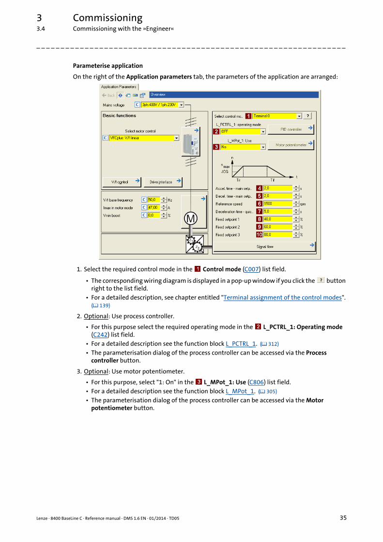
Parameterise application
On the right of the Application parameters tab, the parameters of the application are arranged:
1. Select the required control mode in the Control mode (C007) list field.
• The corresponding wiring diagram is displayed in a pop-up window if you click the button right to the list field.
• For a detailed description, see chapter entitled "Terminal assignment of the control modes". ( 139)
2. Optional: Use process controller.
• For this purpose select the required operating mode in the L_PCTRL_1: Operating mode (C242) list field.
• For a detailed description see the function block L_PCTRL_1. ( 312) • The parameterisation dialog of the process controller can be accessed via the Process
controller button.
3. Optional: Use motor potentiometer.
• For this purpose, select "1: On" in the L_MPot_1: Use (C806) list field.• For a detailed description see the function block L_MPot_1. ( 305) • The parameterisation dialog of the process controller can be accessed via the Motor
potentiometer button.

3 Commissioning3.4 Commissioning with the »Engineer«
36 Lenze · 8400 BaseLine C · Reference manual · DMS 1.6 EN · 01/2014 · TD05
_ _ _ _ _ _ _ _ _ _ _ _ _ _ _ _ _ _ _ _ _ _ _ _ _ _ _ _ _ _ _ _ _ _ _ _ _ _ _ _ _ _ _ _ _ _ _ _ _ _ _ _ _ _ _ _ _ _ _ _ _ _ _ _
4. Adapt parameters of the application:
Tip!• Via the Signal flow button, you get one dialog level lower to the signal flow of the appli-
cation with further parameterisation opportunities. See chapter entitled "Parameterisation dialog". ( 122)
• The preconfigured I/O connection in the selected control mode can be changed via con-figuration parameters. See chapter entitled "User-defined terminal assignment". ( 114)
More detailed information on the drive application:
Drive application ( 121)
Interface description ( 127)
Setting parameters (short overview) ( 132)
Pre-assignment of the drive application ( 133)
Terminal assignment of the control modes ( 139)
Parameter Lenze setting Info
Value Unit
Accel. time - main setpoint(C012)
2.0 s The setpoint is led via a ramp function generator with li-near characteristic. The ramp function generator con-verts setpoint step-changes at the input into a ramp.L_NSet_1 ( 309) Decel. time - main setpoint
(C013)2.0 s
Reference speed(C011)
1500 rpm All speed setpoint selections are provided in % and al-ways refer to the reference speed set in C011.The motor reference speed is given on the motor name-plate.
Deceleration time - quick stop(C105)
5.0 s When "quick stop" is requested, the motor control is de-coupled from the setpoint selection and within the de-celeration time parameterised in C105, the motor is brought to a standstill in (nact = 0).Activate/Deactivate quick stop ( 50)
Fixed setpoint 1(C039/1)
40.0 % A fixed setpoint for the setpoint generator can be acti-vated instead of the main setpoint via the digital inputs DI1 and DI2.
• The fixed setpoints are selected in [%] based on the reference speed (C011).
L_NSet_1 ( 309)
Fixed setpoint 2(C039/2)
60.0 %
Fixed setpoint 3(C039/3)
80.0 %
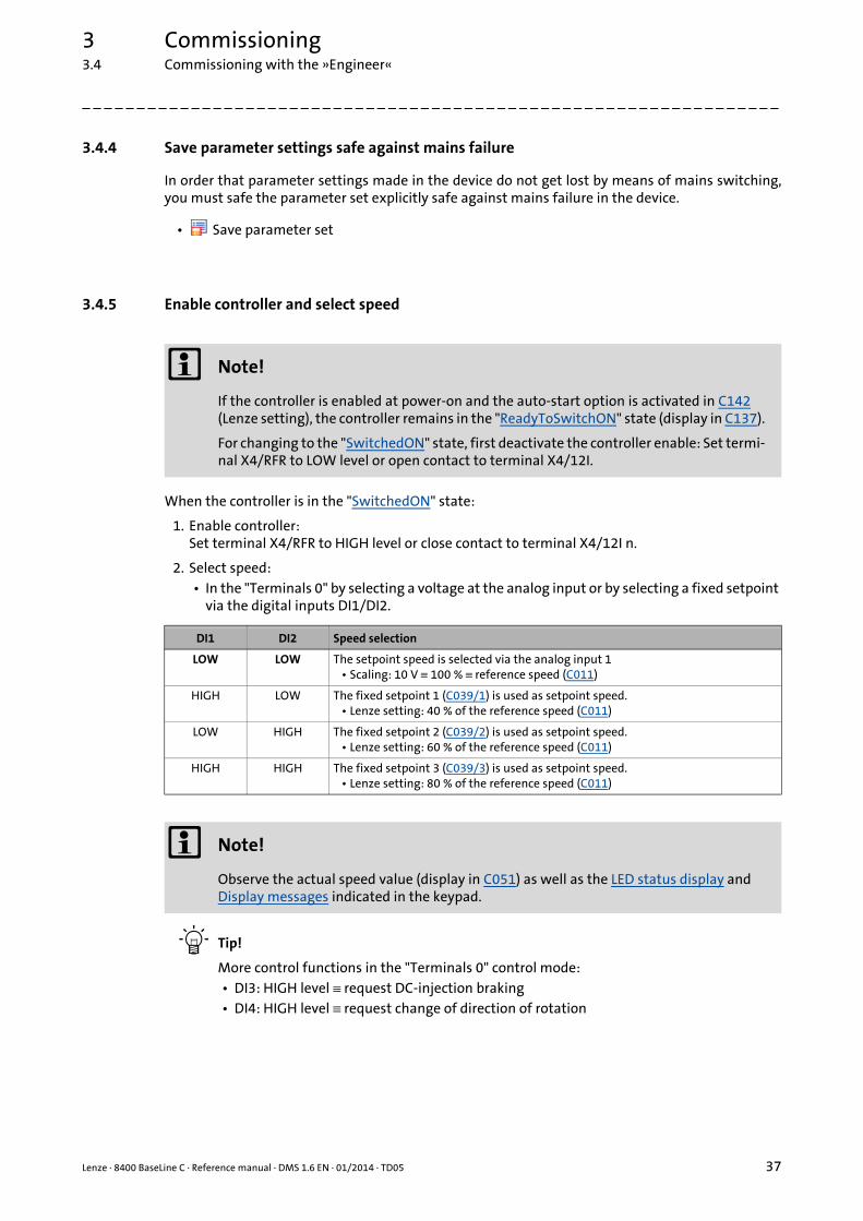
Lenze · 8400 BaseLine C · Reference manual · DMS 1.6 EN · 01/2014 · TD05 37
3 Commissioning3.4 Commissioning with the »Engineer«
_ _ _ _ _ _ _ _ _ _ _ _ _ _ _ _ _ _ _ _ _ _ _ _ _ _ _ _ _ _ _ _ _ _ _ _ _ _ _ _ _ _ _ _ _ _ _ _ _ _ _ _ _ _ _ _ _ _ _ _ _ _ _ _
3.4.4 Save parameter settings safe against mains failure
In order that parameter settings made in the device do not get lost by means of mains switching,you must safe the parameter set explicitly safe against mains failure in the device.
• Save parameter set
3.4.5 Enable controller and select speed
When the controller is in the "SwitchedON" state:
1. Enable controller:Set terminal X4/RFR to HIGH level or close contact to terminal X4/12I n.
2. Select speed:• In the "Terminals 0" by selecting a voltage at the analog input or by selecting a fixed setpoint
via the digital inputs DI1/DI2.
Tip!
More control functions in the "Terminals 0" control mode:• DI3: HIGH level ≡ request DC-injection braking• DI4: HIGH level ≡ request change of direction of rotation
Note!
If the controller is enabled at power-on and the auto-start option is activated in C142 (Lenze setting), the controller remains in the "ReadyToSwitchON" state (display in C137).
For changing to the "SwitchedON" state, first deactivate the controller enable: Set termi-nal X4/RFR to LOW level or open contact to terminal X4/12I.
DI1 DI2 Speed selection
LOW LOW The setpoint speed is selected via the analog input 1• Scaling: 10 V ≡ 100 % ≡ reference speed (C011)
HIGH LOW The fixed setpoint 1 (C039/1) is used as setpoint speed.• Lenze setting: 40 % of the reference speed (C011)
LOW HIGH The fixed setpoint 2 (C039/2) is used as setpoint speed.• Lenze setting: 60 % of the reference speed (C011)
HIGH HIGH The fixed setpoint 3 (C039/3) is used as setpoint speed.• Lenze setting: 80 % of the reference speed (C011)
Note!
Observe the actual speed value (display in C051) as well as the LED status display and Display messages indicated in the keypad.

3 Commissioning3.4 Commissioning with the »Engineer«
38 Lenze · 8400 BaseLine C · Reference manual · DMS 1.6 EN · 01/2014 · TD05
_ _ _ _ _ _ _ _ _ _ _ _ _ _ _ _ _ _ _ _ _ _ _ _ _ _ _ _ _ _ _ _ _ _ _ _ _ _ _ _ _ _ _ _ _ _ _ _ _ _ _ _ _ _ _ _ _ _ _ _ _ _ _ _
Diagnostics options
When the »Engineer« is used, trouble during commissioning can be detected and eliminated conve-niently. Proceed as follows:
• Check whether error messages appear in the »Engineer«.• You can find a description of each possible message in the chapter entitled "Diagnostics &
error management". ( 145)
• Check the input terminals for their corresponding setpoints.• The Terminal assignment tab displays the current input/output signals.
• Check the signal flow of the application.• To do this, open the Application Parameters tab and click on the Signal flow button. The sig-
nal flow which is then shown enables a view of the setpoints being applied and their proces-sing.

Lenze · 8400 BaseLine C · Reference manual · DMS 1.6 EN · 01/2014 · TD05 39
3 Commissioning3.5 PC manual control
_ _ _ _ _ _ _ _ _ _ _ _ _ _ _ _ _ _ _ _ _ _ _ _ _ _ _ _ _ _ _ _ _ _ _ _ _ _ _ _ _ _ _ _ _ _ _ _ _ _ _ _ _ _ _ _ _ _ _ _ _ _ _ _
3.5 PC manual control
This function extension is available as of version 03.03.00 and is supported by the »Engineer« as ofversion 2.14!
For test and demonstration purposes, PC manual control can be used to manually control variousdrive functions via the »Engineer« when an online connection has been established.
Supported drive functions:
• Speed control (follow a speed setpoint)
• Activate/Deactivate quick stop
More control functions:
• Reset of error message
• Set digital/analog outputs (in preparation)
Diagnostic functions:
• Display of the actual speed value and motor current (in a temporal characteristic)
• Display of the current device state
• Display of the status determining error
• Display of the status of the digital/analog inputs (in preparation)
3.5.1 Activating PC manual control
Stop!
PC manual control must be explicitly activated by the user.
If PC manual control is activated, the controller is inhibited via device command (C002/16) first.
Note!
For activated PC manual control:
The online connection between the PC and the controller is monitored by the controller.• If the online connection is interrupted for longer than 2 s, error response "Fault" is trig-
gered, i.e. the motor becomes torqueless and is coasting unless it already is at stand-still.
PC manual control transmits all required control and setpoint signals to the motor inter-face.• The application is now decoupled from these interfaces, but will be processed as be-
fore and remains unchanged.• It does not matter what type of motor control is set in C006.

3 Commissioning3.5 PC manual control
40 Lenze · 8400 BaseLine C · Reference manual · DMS 1.6 EN · 01/2014 · TD05
_ _ _ _ _ _ _ _ _ _ _ _ _ _ _ _ _ _ _ _ _ _ _ _ _ _ _ _ _ _ _ _ _ _ _ _ _ _ _ _ _ _ _ _ _ _ _ _ _ _ _ _ _ _ _ _ _ _ _ _ _ _ _ _
How to activate PC manual control:
1. If an online connection to the controller has not been established yet:
Go online.
2. Go to Workspace and change to the Application parameters tab.
3. Go to the Overview dialog level and click the PC manual control button.• The following safety note is displayed first:
• Click the Cancel button to abort the action and close the dialog box.
4. To acknowledge the note and activate PC manual control:Click the Connect PC manual control button.• The controller is inhibited via device command (C002/16).• The PC manual control operator dialog is displayed.
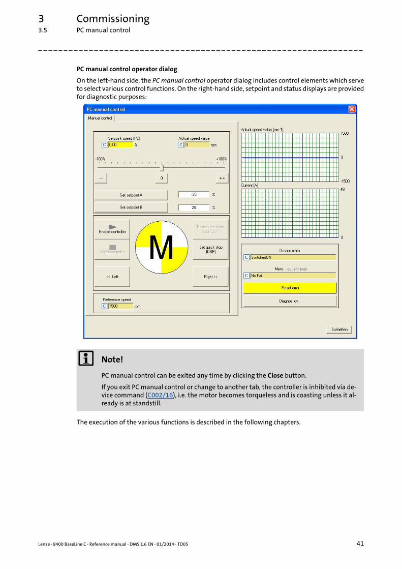
Lenze · 8400 BaseLine C · Reference manual · DMS 1.6 EN · 01/2014 · TD05 41
3 Commissioning3.5 PC manual control
_ _ _ _ _ _ _ _ _ _ _ _ _ _ _ _ _ _ _ _ _ _ _ _ _ _ _ _ _ _ _ _ _ _ _ _ _ _ _ _ _ _ _ _ _ _ _ _ _ _ _ _ _ _ _ _ _ _ _ _ _ _ _ _
PC manual control operator dialog
On the left-hand side, the PC manual control operator dialog includes control elements which serveto select various control functions. On the right-hand side, setpoint and status displays are providedfor diagnostic purposes:
The execution of the various functions is described in the following chapters.
Note!
PC manual control can be exited any time by clicking the Close button.
If you exit PC manual control or change to another tab, the controller is inhibited via de-vice command (C002/16), i.e. the motor becomes torqueless and is coasting unless it al-ready is at standstill.

3 Commissioning3.5 PC manual control
42 Lenze · 8400 BaseLine C · Reference manual · DMS 1.6 EN · 01/2014 · TD05
_ _ _ _ _ _ _ _ _ _ _ _ _ _ _ _ _ _ _ _ _ _ _ _ _ _ _ _ _ _ _ _ _ _ _ _ _ _ _ _ _ _ _ _ _ _ _ _ _ _ _ _ _ _ _ _ _ _ _ _ _ _ _ _
3.5.2 Speed control
Via the Speed control tab, simply make the drive rotate in the "Speed follower" operating mode wi-thout the need to set control parameters or feedback systems:
How to make the motor rotate in its most basic way:
1. Set the desired speed setpoint in [%] based on the reference speed, e.g. directly in the Setpoint PC input field or via the slider.• Via the -- / 0 / ++ buttons, the currently set speed setpoint can be reduced/increased in
steps of 10 percent or set to zero.• Via the Set setpoint A/B buttons, the speed setpoint can be set to a previously set con-
stant value A/B.
2. To start the speed follower:Enable the controller via the Enable controller button.• Please observe that the controller will not be enabled if other sources of controller inhi-
bit (e.g. terminal RFR) are active.• The enabled controller is now following the selected speed setpoint.• To avoid shocks or overload in case of great setpoint changes, the speed setpoint follows
a linear ramp generator with adjustable acceleration/deceleration time.• Via the Inhibit controller button, the controller can be inhibited again, i.e. the motor be-
comes torqueless and is coasting unless it already is at standstill.
Lenze · 8400 BaseLine C · Reference manual · DMS 1.6 EN · 01/2014 · TD05 43
3 Commissioning3.5 PC manual control
_ _ _ _ _ _ _ _ _ _ _ _ _ _ _ _ _ _ _ _ _ _ _ _ _ _ _ _ _ _ _ _ _ _ _ _ _ _ _ _ _ _ _ _ _ _ _ _ _ _ _ _ _ _ _ _ _ _ _ _ _ _ _ _
Further functions:
• If the Set quick stop (QSP) button is clicked, the motor is braked to a standstill within the dece-leration time parameterised in C105.• Via the Deactivate quick stop (QSP) button, the quick stop can be deactivated.
• Via the << Left and Right >> buttons, the direction of rotation can be changed.
4 Device control (DCTRL)
44 Lenze · 8400 BaseLine C · Reference manual · DMS 1.6 EN · 01/2014 · TD05
_ _ _ _ _ _ _ _ _ _ _ _ _ _ _ _ _ _ _ _ _ _ _ _ _ _ _ _ _ _ _ _ _ _ _ _ _ _ _ _ _ _ _ _ _ _ _ _ _ _ _ _ _ _ _ _ _ _ _ _ _ _ _ _
4 Device control (DCTRL)
This chapter provides information on the internal device control as well as the device commandswhich can be executed via the subcodes of C002 .
• The device control causes the controller to take defined device states.
• The device control provides a multitude of status information in many ways:• Optically via the LED status display of the integrated keypad. ( 18) • As text messages in the Logbook. ( 149) • As process signals via the outputs of the LS_DriveInterface system block. ( 325) • Via diagnostic / display parameters which are included in the »Engineer« parameter list as
well as in the Diagnostics category in the keypad.
Note!
The device states of the controller are based on the operating states of the CiA402 stan-dard. Device states ( 53)

Lenze · 8400 BaseLine C · Reference manual · DMS 1.6 EN · 01/2014 · TD05 45
4 Device control (DCTRL)
_ _ _ _ _ _ _ _ _ _ _ _ _ _ _ _ _ _ _ _ _ _ _ _ _ _ _ _ _ _ _ _ _ _ _ _ _ _ _ _ _ _ _ _ _ _ _ _ _ _ _ _ _ _ _ _ _ _ _ _ _ _ _ _
How to get to the parameterisation dialog of the device control:
1. »Engineer« Go to the Project view and select the 8400 BaseLine C controller.
2. Go to Workspace and change to the Application parameters tab.
3. Go to the Overview dialog level and click the Drive interface button.
Parameterisation dialog in the »Engineer«
The parameterisation dialog shows the input / output signals and the internal signal flow of theLS_DriveInterface system block which displays the device control in the application:
Range / Meaning Display parameter
Display of the CAN control word C136/2
Display of the internal state machine and the current device state C137
Display of all active sources of a controller inhibit C158
Display of all active sources of a quick stop C159
Display of the status word of the device control C150
4 Device control (DCTRL)4.1 Device commands
46 Lenze · 8400 BaseLine C · Reference manual · DMS 1.6 EN · 01/2014 · TD05
_ _ _ _ _ _ _ _ _ _ _ _ _ _ _ _ _ _ _ _ _ _ _ _ _ _ _ _ _ _ _ _ _ _ _ _ _ _ _ _ _ _ _ _ _ _ _ _ _ _ _ _ _ _ _ _ _ _ _ _ _ _ _ _
4.1 Device commands
The following subchapters describe the device commands which are provided in the subcodes ofC002 002 and can be carried out using the keypad or, alternatively, the »Engineer« when an onlineconnection has been established.
The device commands serve to directly control the controller, to organise parameter sets, and to calldiagnostic services.
Regarding the execution of the device commands, a distinction is drawn between:
• Device commands which have an immediate effect on control (e.g. "Activate quick stop")• After being called in C002/x, these device commands provide static status information ("On"
or "Off").
• Device commands with longer execution durations (several seconds)• After being called in C002/x, these device commands provide the status information "Work
in progress".• The execution of the device command has not finished successfully until the "Off / ready" sta-
tus information is provided in C002/x.• In the event of an error, the "Action cancelled" status information is provided in C002/x . In
this case, further details can be obtained from the status of the device command executed last which is displayed in C003.
Note!
• Before activating the device commands through a master control, please wait for the "ready" message of the controller.
• The device will reject a write process to C002/x if the value is >1 and issue an error message.
• C003 displays the status of the device command executed last..
Detailed information on the various device commands can be found in the following subchapters.• Before you follow the instructions given therein, ensure that you have selected the
controller in the Project view.
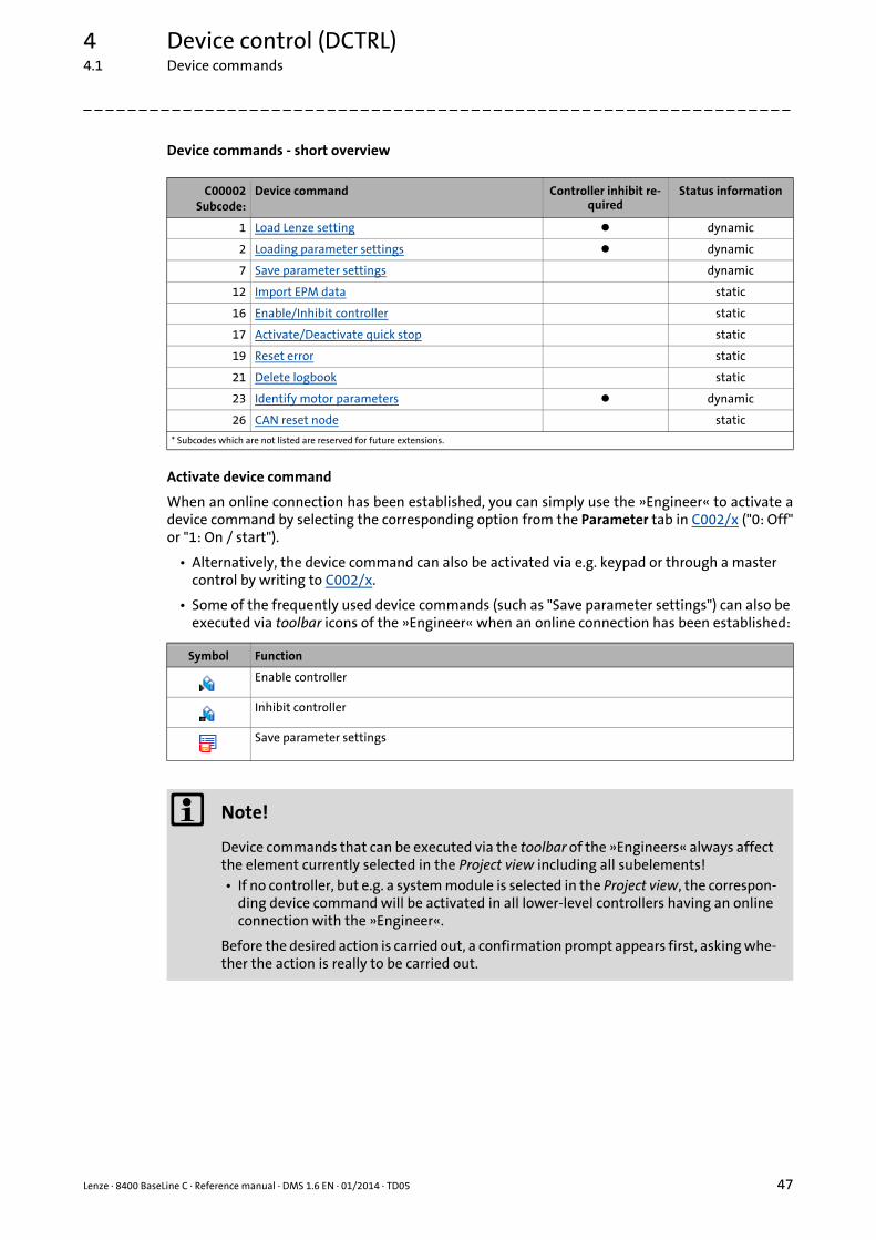
Lenze · 8400 BaseLine C · Reference manual · DMS 1.6 EN · 01/2014 · TD05 47
4 Device control (DCTRL)4.1 Device commands
_ _ _ _ _ _ _ _ _ _ _ _ _ _ _ _ _ _ _ _ _ _ _ _ _ _ _ _ _ _ _ _ _ _ _ _ _ _ _ _ _ _ _ _ _ _ _ _ _ _ _ _ _ _ _ _ _ _ _ _ _ _ _ _
Device commands - short overview
Activate device command
When an online connection has been established, you can simply use the »Engineer« to activate adevice command by selecting the corresponding option from the Parameter tab in C002/x ("0: Off"or "1: On / start").
• Alternatively, the device command can also be activated via e.g. keypad or through a master control by writing to C002/x.
• Some of the frequently used device commands (such as "Save parameter settings") can also be executed via toolbar icons of the »Engineer« when an online connection has been established:
C00002Subcode:
Device command Controller inhibit re-quired
Status information
1 Load Lenze setting dynamic
2 Loading parameter settings dynamic
7 Save parameter settings dynamic
12 Import EPM data static
16 Enable/Inhibit controller static
17 Activate/Deactivate quick stop static
19 Reset error static
21 Delete logbook static
23 Identify motor parameters dynamic
26 CAN reset node static
* Subcodes which are not listed are reserved for future extensions.
Symbol Function
Enable controller
Inhibit controller
Save parameter settings
Note!
Device commands that can be executed via the toolbar of the »Engineers« always affect the element currently selected in the Project view including all subelements!• If no controller, but e.g. a system module is selected in the Project view, the correspon-
ding device command will be activated in all lower-level controllers having an online connection with the »Engineer«.
Before the desired action is carried out, a confirmation prompt appears first, asking whe-ther the action is really to be carried out.

4 Device control (DCTRL)4.1 Device commands
48 Lenze · 8400 BaseLine C · Reference manual · DMS 1.6 EN · 01/2014 · TD05
_ _ _ _ _ _ _ _ _ _ _ _ _ _ _ _ _ _ _ _ _ _ _ _ _ _ _ _ _ _ _ _ _ _ _ _ _ _ _ _ _ _ _ _ _ _ _ _ _ _ _ _ _ _ _ _ _ _ _ _ _ _ _ _
4.1.1 Load Lenze setting
The C002/1 = "1: : On / start" device command resets the parameters to the Lenze setting which aresaved in the controller firmware.
• Can only be executed if the controller is inhibited; otherwise, the feedback C002/1 = "6: No ac-cess - controller inhibit" will be returned.
• All parameter changes which have been carried out after the last time the parameter settings were saved will be lost!
• This device command has an effect on the settings of the parameters of the operating system, application and module.
How to load the Lenze setting:
1. If the controller is enabled, it must be inhibited, e.g. by executing the "Enable/Inhibit cont-roller" device command" (C002/16 = "0: Off / ready").
2. Execute the "Load Lenze setting" device commandC002/1 = "1: On / start"
The load process may take a couple of seconds. After the device command has been called in C002/1 a dynamic status information ("Work in progress" "Off / ready") is returned.
4.1.2 Loading parameter settings
The C002/2 = "1: On / start" device command reloads all parameters from the memory module tothe controller.
• Can only be executed if the controller is inhibited; otherwise, the feedback C002/2 = "6: No ac-cess - controller inhibit" will be returned.
• All parameter changes which have been carried out after the last time the parameter settings were saved will be lost!
• This device command has an effect on the settings of the parameters of the operating system, application and module.
How to reload the starting parameter settings from the memory module:
1. If the controller is enabled, it must be inhibited, e.g. by executing the "Enable/Inhibit cont-roller" device command (C002/16 = "0: Off / ready").
2. Execute the "Load Lenze setting" device command:C002/2 = "1: On / start"
The load process may take a couple of seconds. After the device command has been called in C002/2 2 a dynamic status information ("Work in progress" "Off / ready") is returned.
Note!
When the device is switched on, all parameters are automatically loaded from the me-mory module to the main memory of the controller.

Lenze · 8400 BaseLine C · Reference manual · DMS 1.6 EN · 01/2014 · TD05 49
4 Device control (DCTRL)4.1 Device commands
_ _ _ _ _ _ _ _ _ _ _ _ _ _ _ _ _ _ _ _ _ _ _ _ _ _ _ _ _ _ _ _ _ _ _ _ _ _ _ _ _ _ _ _ _ _ _ _ _ _ _ _ _ _ _ _ _ _ _ _ _ _ _ _
4.1.3 Save parameter settings
If parameter settings are changed in the controller, those changes will be lost after mains switchingof the controller unless the settings have been saved explicitly.
You have various opportunities to prevent a data loss by saving the parameter settings in the me-mory module:
• Quick saving of all parameters at the push of a button ( 23)
• Automatic saving of parameter changes
• Manual saving of parameter settings
Automatic saving of parameter changes
When you set the selection "1: Active" in C141/1, the automatic saving function is activated andevery parameter change is automatically saved in the memory module. Thus, manual saving of pa-rameter settings is not required anymore.
Manual saving of parameter settings
The C002/7 = "1: On / start" device command saves the current parameter settings safe againstmains failure to the memory module of the controller.
Note!
How to prevent a data loss:• Do not switch off the supply voltage during the saving process.• Only unplug the memory module if the device is switched off.
Stop!
Activating this function is not permissible if parameters are changed very frequently (e.g. in case of cyclic writing of parameters via a bus system).
The maximum service life of the memory module amounts to one million writing cycles. Make sure that this value will not be reached.

4 Device control (DCTRL)4.1 Device commands
50 Lenze · 8400 BaseLine C · Reference manual · DMS 1.6 EN · 01/2014 · TD05
_ _ _ _ _ _ _ _ _ _ _ _ _ _ _ _ _ _ _ _ _ _ _ _ _ _ _ _ _ _ _ _ _ _ _ _ _ _ _ _ _ _ _ _ _ _ _ _ _ _ _ _ _ _ _ _ _ _ _ _ _ _ _ _
4.1.4 Import EPM data
The C002/12 = "1: On / start" device command activates the automatic import of parameters fromthe memory module after the error message "PS04: Par.set incompatible".
4.1.5 Enable/Inhibit controller
The C002/16 = "1: On / start" device command enables the controller, provided that no other sourceof a controller inhibit is active.
The C002/16 = "0: : On / start" device command enables the controller, provided that no other sour-ce of a controller inhibit is active.
• The motor becomes torqueless and coasts down.
• When the controller is inhibited, the status output bCInhActive of the LS_DriveInterface system block is set to TRUE.
• When the controller inhibit request is reset, the drive synchronises to the actual speed. For this purpose,• If the flying restart circuit is activated in C990, the flying restart function parameterised in
C991 is used for the synchronisation to the rotary or standing drive. Flying restart function ( 94)
Tip!
• The controller can also be enabled or inhibited via the and toolbar icons.• C158 provides a bit coded representation of all active sources/triggers of a controller in-
hibit.
4.1.6 Activate/Deactivate quick stop
The C002/17 = "1: On / start" device command activates the quick stop function, i.e. the motor con-trol is separated from the setpoint selection, and within the deceleration time parameterised inC105 the motor is brought to a standstill (nact = 0).
• A pulse inhibit (CINH) is set if the "Auto-DCB" function has been activated via C019.
The C002/17 = "0: Off / ready" device command deactivates the quick stop again, provided that noother source of a quick stop is active.
Tip!
C159 provides a bit coded representation of all active sources/triggers of a quick stop.
Parameter Info Lenze setting
Value Unit
C105 Deceleration time - quick stop 2.000 s
Lenze · 8400 BaseLine C · Reference manual · DMS 1.6 EN · 01/2014 · TD05 51
4 Device control (DCTRL)4.1 Device commands
_ _ _ _ _ _ _ _ _ _ _ _ _ _ _ _ _ _ _ _ _ _ _ _ _ _ _ _ _ _ _ _ _ _ _ _ _ _ _ _ _ _ _ _ _ _ _ _ _ _ _ _ _ _ _ _ _ _ _ _ _ _ _ _
4.1.7 Reset error
The C002/19 = "1: On / start" device command acknowledges an existing error message if the errorcause has been eliminated and thus the error is not pending anymore.
• After resetting the current error, further errors may be pending which must be reset as well.
• The last 8 errors are displayed in C168.
Tip!
An error message can also be acknowledged by activating the Reset error button in theDiagnostics tab.
In the Lenze setting, switching RFR also causes an error acknowledgement (see configura-tion parameter C701/2).
Detailed information on error messages can be found in the chapter entitled "Diagnostics& error management". ( 145)
4.1.8 Delete logbook
The C002/21 = "1: On / start" device command deletes all logbook entries.
Tip!
Click the Logbook button in the Diagnostics tab to display the logbook in the »Engineer«.
In the Logbook dialog box, it is also possible to delete all logbook entries by clicking theDelete button.
Detailed information on the logbook can be found in the chapter entitled "Diagnostics &error management". ( 145)
4.1.9 Identify motor parameters
The C002/23 = "1: On / start" device command performs automatic identification of the motor pa-rameters.
• The device command is only executed when the drive controller is in the "SwitchedON" state.
• In order to identify the motor parameters, the controller must be enabled after this device com-mand.• After that it changes to the "MotorIdent" device state.• After the execution of the identification, it changes back to the "SwitchedON" device state.
Tip!
Detailed information on automatic identification of motor parameters can be found in the"Automatic motor data identification" subchapter on motor control (MCTRL). ( 70)

4 Device control (DCTRL)4.1 Device commands
52 Lenze · 8400 BaseLine C · Reference manual · DMS 1.6 EN · 01/2014 · TD05
_ _ _ _ _ _ _ _ _ _ _ _ _ _ _ _ _ _ _ _ _ _ _ _ _ _ _ _ _ _ _ _ _ _ _ _ _ _ _ _ _ _ _ _ _ _ _ _ _ _ _ _ _ _ _ _ _ _ _ _ _ _ _ _
4.1.10 CAN reset node
The C002/26 = "1: On / start" device command reinitialises the CAN interface which is required aftere.g. changing the data transfer rate, the node address, or identifiers..
General information on the CAN interface can be found in the chapter entitled "System bus "CAN on board"". ( 169)

Lenze · 8400 BaseLine C · Reference manual · DMS 1.6 EN · 01/2014 · TD05 53
4 Device control (DCTRL)4.2 Device states
_ _ _ _ _ _ _ _ _ _ _ _ _ _ _ _ _ _ _ _ _ _ _ _ _ _ _ _ _ _ _ _ _ _ _ _ _ _ _ _ _ _ _ _ _ _ _ _ _ _ _ _ _ _ _ _ _ _ _ _ _ _ _ _
4.2 Device states
The state machine causes the controller to take defined states:
• The arrows between the device states mark the points where the possible device states begin and end.
• The digits stand for the state ID (see table below).
Device state machine
Grey field: pulse inhibit
Can be reached from all states.
"Warning" contradicts the definition of a device state. In fact, it is a message which is to call attention to the device state the warning exists for."Warning" can occur in parallel to other states.
ReadyToSwitchOn
3
SwitchedOn4
OperationEnabled
5
Trouble7
�
SafeTorqueOff10
�
MotorIdent2
�
Warning
Fault8
Init1
Power on

4 Device control (DCTRL)4.2 Device states
54 Lenze · 8400 BaseLine C · Reference manual · DMS 1.6 EN · 01/2014 · TD05
_ _ _ _ _ _ _ _ _ _ _ _ _ _ _ _ _ _ _ _ _ _ _ _ _ _ _ _ _ _ _ _ _ _ _ _ _ _ _ _ _ _ _ _ _ _ _ _ _ _ _ _ _ _ _ _ _ _ _ _ _ _ _ _
• The change from one state to another is done in a 1 ms cycle. If, at the same time, several state change requests exist, the state with the higher priority is processed first (see the following ta-ble).
• C137 displays the current device state.
• C150(status word) provides a bit coded representation of the current device state via bits 8 ... 11 (see table below).
[4-1] Device states, priorities, and meaning of the status bits in the status word
ID Device state(Display in C137)
Priority Status bits(display in C150)
Meaning
Bit 11 Bit 10 Bit 9 Bit 8
0 - (reserved) - 0 0 0 0 -
1 Init - 0 0 0 1 Initialisation is active
2 MotorIdent - 0 0 1 0 Motor parameter identification is acti-ve
3 ReadyToSwitchON Prio 4 0 0 1 1 Device is ready to start
4 SwitchedON Prio 3 0 1 0 0 Device is switched on
5 OperationEnabled Prio 1 0 1 0 1 Operation
6 - (reserved) - 0 1 1 0 -
7 Trouble Prio 2 0 1 1 1 Trouble is active
8 Fault Prio 6 1 0 0 0 Fault is active
9 - (reserved) - 1 0 0 1 -
10 SafeTorqueOff Prio 5 1 0 1 0 Safe torque off is active
11 - (reserved) - 1 0 1 1 -
... ... ... ... ...
15 - (reserved) - 1 1 1 1 -

Lenze · 8400 BaseLine C · Reference manual · DMS 1.6 EN · 01/2014 · TD05 55
4 Device control (DCTRL)4.2 Device states
_ _ _ _ _ _ _ _ _ _ _ _ _ _ _ _ _ _ _ _ _ _ _ _ _ _ _ _ _ _ _ _ _ _ _ _ _ _ _ _ _ _ _ _ _ _ _ _ _ _ _ _ _ _ _ _ _ _ _ _ _ _ _ _
4.2.1 Init
In the "Init" device status
• is the controller directly after the supply voltage is switched on.
• the operating system is initialised.
• all device components (memory module, power section, etc.) are identified.
• the parameters are read out of the memory module.
• it is checked whether the DC-bus voltage is within the tolerance zone and the precharge relay is closed.
• the inverter is inhibited, i.e., there is no voltage output at the motor terminals.
• the communication via CAN and diagnostic interface does not work yet.
• the application is not yet processed.
• the monitoring mode is not yet active.
• the controller cannot be parameterised yet and no device commands can be carried out yet.
LED DRIVE READY LED DRIVE ERROR Display in C137 Display in status word 1 (C150)
Bit 11 Bit 10 Bit 9 Bit 8
OFF OFF Init 0 0 0 1
Note!
If the initialisation is completed, it changes automatically to the "ReadyToSwitchON" de-vice state.

4 Device control (DCTRL)4.2 Device states
56 Lenze · 8400 BaseLine C · Reference manual · DMS 1.6 EN · 01/2014 · TD05
_ _ _ _ _ _ _ _ _ _ _ _ _ _ _ _ _ _ _ _ _ _ _ _ _ _ _ _ _ _ _ _ _ _ _ _ _ _ _ _ _ _ _ _ _ _ _ _ _ _ _ _ _ _ _ _ _ _ _ _ _ _ _ _
4.2.2 MotorIdent
In the "MotorIdent" device state
• is the controller when being in the "SwitchedON" state and having activated the "Identify motor parameters" device command and being enabled.
• the application remains active.
• all system interfaces (IO, bus systems, etc.) remain active.
• error monitoring remains active
• the inverter is controlled independently of the setpoint sources.
After the motor parameter identification is completed, the state changes back to "SwitchedON".
Tip!
Detailed information on motor parameter identification can be found in the "Automaticmotor data identification" subchapter on motor control. ( 70)
4.2.3 SafeTorqueOff
In the "SafeTorqueOff" device state
• the controller can only be if a safety module is connected and the power section is supplied and at least one of the two safe inputs SI1/SI2 is set to LOW level.
• the next transaction to the "ReadyToSwitchON" state takes place.
LED DRIVE READY LED DRIVE ERROR Display in C137 Display in status word 1 (C150)
Bit 11 Bit 10 Bit 9 Bit 8
OFF MotorIdent 0 0 1 0
Stop!
During motor parameter identification, the controller does not respond to setpoint changes or control processes, (e.g. speed setpoints, quick stop, torque limitations).
LED DRIVE READY LED DRIVE ERROR Display in C137 Display in status word 1 (C150)
Bit 11 Bit 10 Bit 9 Bit 8
OFF SafeTorqueOff 1 0 1 0
Detailed and important information on the integrated safety system can be found in the hardware manual!

Lenze · 8400 BaseLine C · Reference manual · DMS 1.6 EN · 01/2014 · TD05 57
4 Device control (DCTRL)4.2 Device states
_ _ _ _ _ _ _ _ _ _ _ _ _ _ _ _ _ _ _ _ _ _ _ _ _ _ _ _ _ _ _ _ _ _ _ _ _ _ _ _ _ _ _ _ _ _ _ _ _ _ _ _ _ _ _ _ _ _ _ _ _ _ _ _
4.2.4 ReadyToSwitchON
In the "ReadyToSwitchOn" device state
• is the controller after the initialisation has been completed successfully.
• is the controller even after cancelling "Trouble", "Fault" or "SafeTorqueOff".
• I/O signalare evaluated.
• the monitoring modes are active.
• the controller can be parameterised.
• the application is basically executable.
• prevents in the Lenze setting the auto-start option "Inhibit at power-on" activated in C142 from changing to the "SwitchedON" state.
LED DRIVE READY LED DRIVE ERROR Display in C137 Display in status word 1 (C150)
Bit 11 Bit 10 Bit 9 Bit 8
OFF ReadyToSwitchON 0 0 1 1
Danger!
If the "Inhibit at power-on" auto-start option has been deactivated in C142 the "Ready-ToSwitchOn" state directly switches to the "SwitchedON" state.
"Inhibit at power-on" auto-start option ( 62)
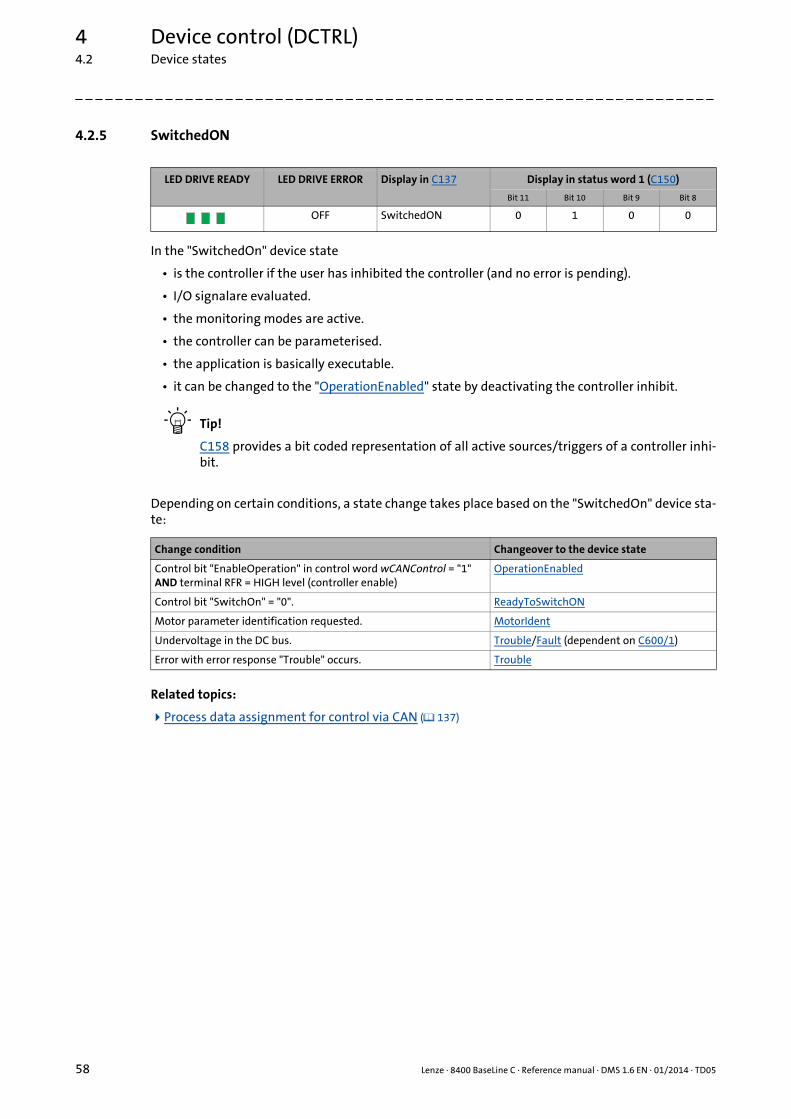
4 Device control (DCTRL)4.2 Device states
58 Lenze · 8400 BaseLine C · Reference manual · DMS 1.6 EN · 01/2014 · TD05
_ _ _ _ _ _ _ _ _ _ _ _ _ _ _ _ _ _ _ _ _ _ _ _ _ _ _ _ _ _ _ _ _ _ _ _ _ _ _ _ _ _ _ _ _ _ _ _ _ _ _ _ _ _ _ _ _ _ _ _ _ _ _ _
4.2.5 SwitchedON
In the "SwitchedOn" device state
• is the controller if the user has inhibited the controller (and no error is pending).
• I/O signalare evaluated.
• the monitoring modes are active.
• the controller can be parameterised.
• the application is basically executable.
• it can be changed to the "OperationEnabled" state by deactivating the controller inhibit.
Tip!
C158 provides a bit coded representation of all active sources/triggers of a controller inhi-bit.
Depending on certain conditions, a state change takes place based on the "SwitchedOn" device sta-te:
Related topics:
Process data assignment for control via CAN ( 137)
LED DRIVE READY LED DRIVE ERROR Display in C137 Display in status word 1 (C150)
Bit 11 Bit 10 Bit 9 Bit 8
OFF SwitchedON 0 1 0 0
Change condition Changeover to the device state
Control bit "EnableOperation" in control word wCANControl = "1"AND terminal RFR = HIGH level (controller enable)
OperationEnabled
Control bit "SwitchOn" = "0". ReadyToSwitchON
Motor parameter identification requested. MotorIdent
Undervoltage in the DC bus. Trouble/Fault (dependent on C600/1)
Error with error response "Trouble" occurs. Trouble

Lenze · 8400 BaseLine C · Reference manual · DMS 1.6 EN · 01/2014 · TD05 59
4 Device control (DCTRL)4.2 Device states
_ _ _ _ _ _ _ _ _ _ _ _ _ _ _ _ _ _ _ _ _ _ _ _ _ _ _ _ _ _ _ _ _ _ _ _ _ _ _ _ _ _ _ _ _ _ _ _ _ _ _ _ _ _ _ _ _ _ _ _ _ _ _ _
4.2.6 OperationEnabled
In the "OperationEnabled" state
• is the controller if the controller inhibit is deactivated and no trouble ("Trouble") and fault ("Fault") are existent.
• the operation is enabled and the motor follows the setpoint defined by the active application (in case of sensorless vector control only after the magnetisation process is completed).
Depending on certain conditions, a state change takes place based on the "OperationEnabled" de-vice state.
Related topics:
Process data assignment for control via CAN ( 137)
LED DRIVE READY LED DRIVE ERROR Display in C137 Display in status word 1 (C150)
Bit 11 Bit 10 Bit 9 Bit 8
OFF OperationEnabled 0 1 0 1
Change condition Changeover to the device state
Control bit "EnableOperation" in control word wCANControl = "0"OR terminal RFR = LOW level (controller inhibit).
SwitchedON
Control bit "SwitchOn" = "0". ReadyToSwitchON
Undervoltage in the DC bus. Trouble/Fault (dependent on C600/1)
Error with error response "Trouble" occurs. Trouble

4 Device control (DCTRL)4.2 Device states
60 Lenze · 8400 BaseLine C · Reference manual · DMS 1.6 EN · 01/2014 · TD05
_ _ _ _ _ _ _ _ _ _ _ _ _ _ _ _ _ _ _ _ _ _ _ _ _ _ _ _ _ _ _ _ _ _ _ _ _ _ _ _ _ _ _ _ _ _ _ _ _ _ _ _ _ _ _ _ _ _ _ _ _ _ _ _
4.2.7 Trouble
In the "Trouble" device state
• is the controller if monitoring has caused a "Trouble" error response.
• the motor has no torque (is coasting) due to the inhibit of the inverter.
Depending on certain conditions a state change takes place based on the "Trouble" device state.
Related topics:
Process data assignment for control via CAN ( 137)
Basics on error handling in the controller ( 145)
Error messages of the operating system ( 156)
LED DRIVE READY LED DRIVE ERROR Display in C137 Display in status word 1 (C150)
Bit 11 Bit 10 Bit 9 Bit 8
OFF Trouble 0 1 1 1
Note!
The "Trouble" device state is automatically abandoned if the error cause has been remo-ved.
If in C142 the "Inhibit at trouble" auto-start option is activated , an explicit deactivation of the controller inhibit is required for leaving the state.
Change condition Changeover to the device state
The error cause is no longer active. ReadyToSwitchON
Control bit "EnableOperation" in control word wCANControl = "1"AND terminal RFR = HIGH level (controller enable)AND the message has been cancelled.
OperationEnabled
Control bit "EnableOperation" in control word wCANControl = "0"OR terminal RFR = LOW level (controller inhibit)AND the message has been cancelled.
SwitchedON

Lenze · 8400 BaseLine C · Reference manual · DMS 1.6 EN · 01/2014 · TD05 61
4 Device control (DCTRL)4.2 Device states
_ _ _ _ _ _ _ _ _ _ _ _ _ _ _ _ _ _ _ _ _ _ _ _ _ _ _ _ _ _ _ _ _ _ _ _ _ _ _ _ _ _ _ _ _ _ _ _ _ _ _ _ _ _ _ _ _ _ _ _ _ _ _ _
4.2.8 Fault
In the "Fault" device state
• is the controller if monitoring has caused a "Fault" error response.
• the motor has no torque (is coasting) due to the inhibit of the inverter.
The error must explicitly be reset ("acknowledged") in order to exit the device state, e.g. by the de-vice command "Reset error" or via the control bit "ResetFault" in the control word wCANControl.
Related topics:
Process data assignment for control via CAN ( 137)
Basics on error handling in the controller ( 145)
Error messages of the operating system ( 156)
LED DRIVE READY LED DRIVE ERROR Display in C137 Display in status word 1 (C150)
Bit 11 Bit 10 Bit 9 Bit 8
OFF Fault 1 0 0 0
Note!
If an undervoltage in the DC bus of the drive controller occurs (error message "LU"), the device changes to the "Trouble" state.
An additional error of higher priority leads the device into the "Fault" state.
According to the Device state machine, the device changes to the "ReadyToSwitchON" state after acknowledging the error although the undervoltage is still available!
If in C142 the "Inhibit at fault" auto-start option "is activated, an explicit deactivation of the controller inhibit is required for leaving the state.

4 Device control (DCTRL)4.3 "Inhibit at power-on" auto-start option
62 Lenze · 8400 BaseLine C · Reference manual · DMS 1.6 EN · 01/2014 · TD05
_ _ _ _ _ _ _ _ _ _ _ _ _ _ _ _ _ _ _ _ _ _ _ _ _ _ _ _ _ _ _ _ _ _ _ _ _ _ _ _ _ _ _ _ _ _ _ _ _ _ _ _ _ _ _ _ _ _ _ _ _ _ _ _
4.3 "Inhibit at power-on" auto-start option
In the Lenze setting inC142 the auto-start option "Inhibit at power-on" is activated. This setting pre-vents a change to the"SwitchedON"state if the controller is already enabled at mains power-up.
The following three cases describe the controller behaviour as a function of controller enable andset auto-start option. Here, we assume that no fault and trouble exist in the controller after power-on and the control bit "EnableOperation" in the control word wCANControl is set to "1".
Danger!
When the auto-start option "Inhibit at power-on" is deactivated, the motor can directly start after power-on if the controller is enabled!
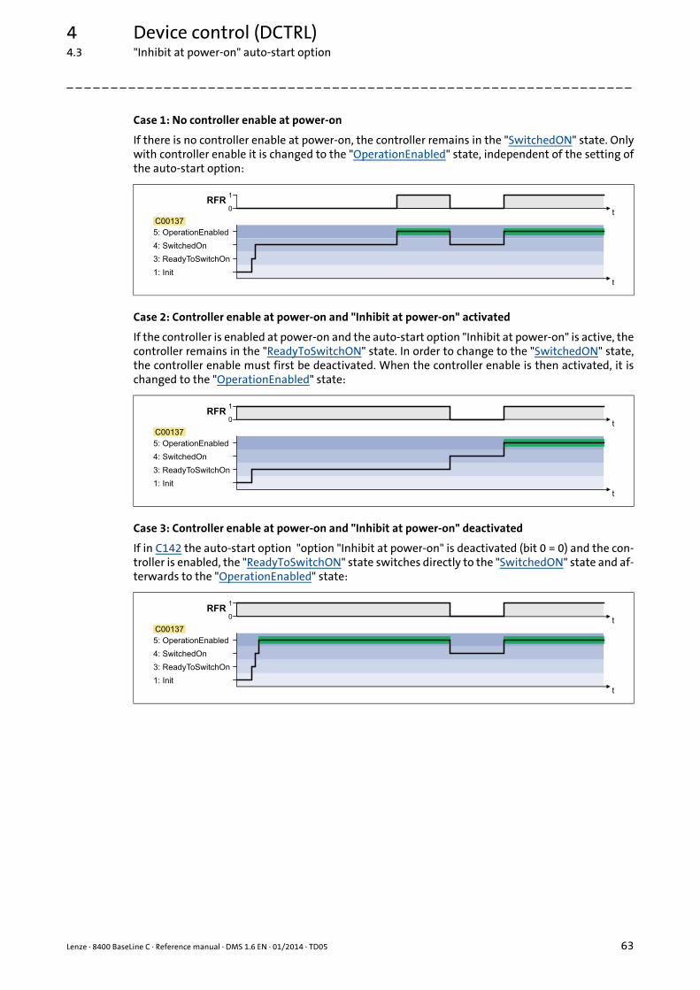
Lenze · 8400 BaseLine C · Reference manual · DMS 1.6 EN · 01/2014 · TD05 63
4 Device control (DCTRL)4.3 "Inhibit at power-on" auto-start option
_ _ _ _ _ _ _ _ _ _ _ _ _ _ _ _ _ _ _ _ _ _ _ _ _ _ _ _ _ _ _ _ _ _ _ _ _ _ _ _ _ _ _ _ _ _ _ _ _ _ _ _ _ _ _ _ _ _ _ _ _ _ _ _
Case 1: No controller enable at power-on
If there is no controller enable at power-on, the controller remains in the "SwitchedON" state. Onlywith controller enable it is changed to the "OperationEnabled" state, independent of the setting ofthe auto-start option:
Case 2: Controller enable at power-on and "Inhibit at power-on" activated
If the controller is enabled at power-on and the auto-start option "Inhibit at power-on" is active, thecontroller remains in the "ReadyToSwitchON" state. In order to change to the "SwitchedON" state,the controller enable must first be deactivated. When the controller enable is then activated, it ischanged to the "OperationEnabled" state:
Case 3: Controller enable at power-on and "Inhibit at power-on" deactivated
If in C142 the auto-start option "option "Inhibit at power-on" is deactivated (bit 0 = 0) and the con-troller is enabled, the "ReadyToSwitchON" state switches directly to the "SwitchedON" state and af-terwards to the "OperationEnabled" state:

5 Motor control (MCTRL)
64 Lenze · 8400 BaseLine C · Reference manual · DMS 1.6 EN · 01/2014 · TD05
_ _ _ _ _ _ _ _ _ _ _ _ _ _ _ _ _ _ _ _ _ _ _ _ _ _ _ _ _ _ _ _ _ _ _ _ _ _ _ _ _ _ _ _ _ _ _ _ _ _ _ _ _ _ _ _ _ _ _ _ _ _ _ _
5 Motor control (MCTRL)
This chapter provides information on the parameter setting of the controller's internal motor cont-rol.
Topics:
Motor selection/Motor data
Selecting the control mode
Defining current and speed limits
V/f characteristic control (VFCplus)
Sensorless vector control (SLVC)
Parameterisable additional functions
Braking operation/braking energy management
Monitoring

Lenze · 8400 BaseLine C · Reference manual · DMS 1.6 EN · 01/2014 · TD05 65
5 Motor control (MCTRL)5.1 Motor selection/Motor data
_ _ _ _ _ _ _ _ _ _ _ _ _ _ _ _ _ _ _ _ _ _ _ _ _ _ _ _ _ _ _ _ _ _ _ _ _ _ _ _ _ _ _ _ _ _ _ _ _ _ _ _ _ _ _ _ _ _ _ _ _ _ _ _
5.1 Motor selection/Motor data
The motor data term comprises all parameters that only depend on the motor and that only charac-terise the electrical behaviour of the machine. The motor data are independent of the application inwhich the controller and the motor are used.
Proceed as follows to open the dialog for parameterising the motor data:
1. »Engineer« Go to the Project view and select the 8400 BaseLine C controller.
2. Go to Workspace and change to the Application parameters tab.
3. Go to the Overview dialog level and click the following button:
Parameterisation dialog in the »Engineer«
• Via the from Motor Catalogue button, the motor catalogue can be opened to select another mo-tor. Selecting a motor from the motor catalogue in the »Engineer« ( 68)
• Via the From drive... button, the motor data set in the controller can be copied to the »Engineer« when an online connection has been established.

5 Motor control (MCTRL)5.1 Motor selection/Motor data
66 Lenze · 8400 BaseLine C · Reference manual · DMS 1.6 EN · 01/2014 · TD05
_ _ _ _ _ _ _ _ _ _ _ _ _ _ _ _ _ _ _ _ _ _ _ _ _ _ _ _ _ _ _ _ _ _ _ _ _ _ _ _ _ _ _ _ _ _ _ _ _ _ _ _ _ _ _ _ _ _ _ _ _ _ _ _
Motor data
In the parameterisation dialog, the data of the motor nameplate for the selected motor are display-ed under "Motor data".
Actual values
When an online connection to the controller has been established, the following actual values aredisplayed in the parameterisation dialog under "Actual values":
Note!
Sensorless vector control in particular requires the motor data parameters to be set. The motor data comprise the data of the motor nameplate and the data of the motor equi-valent circuit.
If the motor has been selected via the motor catalogue of the »Engineer« or the motor data have been adapted offline using the »Engineer«, all motor data must then be co-pied to the controller and saved power-failure-proof to the memory module (device command: C002/11) when an online connection has been established.
Parameter Info
C081 Rated motor power
C087 Rated motor speed
C088 Rated motor current
C089 Rated motor frequency
C090 Rated motor voltage
C091 Motor cos ϕ
Parameter Info
C051 Actual speed value
C052 Motor voltage
C053 DC-bus voltage
C054 Motor current
C066 Thermal motor load (I2xt)
Highlighted in grey = display parameter

Lenze · 8400 BaseLine C · Reference manual · DMS 1.6 EN · 01/2014 · TD05 67
5 Motor control (MCTRL)5.1 Motor selection/Motor data
_ _ _ _ _ _ _ _ _ _ _ _ _ _ _ _ _ _ _ _ _ _ _ _ _ _ _ _ _ _ _ _ _ _ _ _ _ _ _ _ _ _ _ _ _ _ _ _ _ _ _ _ _ _ _ _ _ _ _ _ _ _ _ _
Adapting motor data manually
If a third party manufacturer's motor is used, the displayed motor data can exactly be adapted tothe real motor by clicking the From project... button and selecting the "Own motor settings" entryfrom the Motor selection dialog box afterwards. For this purpose, the data of the motor nameplateand the equivalent circuit diagram must be available.
Tip!
For a better concentricity factor, we recommend to perform motor parameter identificati-on of the third party manufacturer's motor first. The motor parameters can be manuallyadapted afterwards.
Improving the concentricity factor includes• the adjustment of the inverter error characteristic to the drive system and• the knowledge of the motor cable resistance.
Both factors are determined in the course of motor parameter identification.
Automatic motor data identification ( 70)
Other motor data
Click the Other motor data... button and go to the Other motor data dialog box including the motorequivalent circuit:
Parameter Info
C084 Motor stator resistance
C085 Motor stator leakage inductance
C092 Motor magnetising inductance
C015 VFCplus: V/f base frequency
C021 Slip compensation

5 Motor control (MCTRL)5.1 Motor selection/Motor data
68 Lenze · 8400 BaseLine C · Reference manual · DMS 1.6 EN · 01/2014 · TD05
_ _ _ _ _ _ _ _ _ _ _ _ _ _ _ _ _ _ _ _ _ _ _ _ _ _ _ _ _ _ _ _ _ _ _ _ _ _ _ _ _ _ _ _ _ _ _ _ _ _ _ _ _ _ _ _ _ _ _ _ _ _ _ _
5.1.1 Selecting a motor from the motor catalogue in the »Engineer«
If a checkmark is set in the Motor control field in the "Other components" dialog when the controlleris inserted into the project, the motor for the controller can be selected from the motor catalogue inanother dialog:
• Alternatively, the motor can be inserted into the project at a later time via the Insert a component command.
• Go to the Application parameters tab in the Overview Motor data dialog level and click the From motor catalogue... button to also reach the motor catalogue for the selection of another motor.
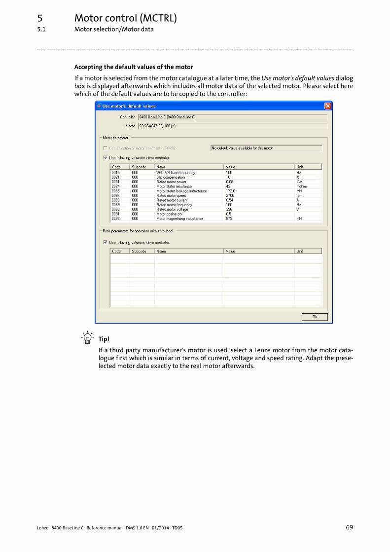
Lenze · 8400 BaseLine C · Reference manual · DMS 1.6 EN · 01/2014 · TD05 69
5 Motor control (MCTRL)5.1 Motor selection/Motor data
_ _ _ _ _ _ _ _ _ _ _ _ _ _ _ _ _ _ _ _ _ _ _ _ _ _ _ _ _ _ _ _ _ _ _ _ _ _ _ _ _ _ _ _ _ _ _ _ _ _ _ _ _ _ _ _ _ _ _ _ _ _ _ _
Accepting the default values of the motor
If a motor is selected from the motor catalogue at a later time, the Use motor's default values dialogbox is displayed afterwards which includes all motor data of the selected motor. Please select herewhich of the default values are to be copied to the controller:
Tip!
If a third party manufacturer's motor is used, select a Lenze motor from the motor cata-logue first which is similar in terms of current, voltage and speed rating. Adapt the prese-lected motor data exactly to the real motor afterwards.

5 Motor control (MCTRL)5.1 Motor selection/Motor data
70 Lenze · 8400 BaseLine C · Reference manual · DMS 1.6 EN · 01/2014 · TD05
_ _ _ _ _ _ _ _ _ _ _ _ _ _ _ _ _ _ _ _ _ _ _ _ _ _ _ _ _ _ _ _ _ _ _ _ _ _ _ _ _ _ _ _ _ _ _ _ _ _ _ _ _ _ _ _ _ _ _ _ _ _ _ _
5.1.2 Automatic motor data identification
Via the "Identify motor parameters" device command " (C002/23), the inverter characteristic, the in-fluences of the motor cable, and the motor parameters listed in the table below can be identifiedautomatically:
Parameter Info
C015 V/f base frequency
C016 Vmin boost
C021 Slip compensation
C084 Motor stator resistance
C085 Motor stator leakage inductance
C092 Motor magnetising inductance
C095 Motor magnetising current
Danger!
During motor parameter identification, the motor is energised via the outputs U, V and W of the controller!
Observe the corresponding safety instructions!
Stop!
If motor parameter identification is aborted, unstable drive behaviour may be the result!
Note!
• We strongly recommend motor parameter identification before the initial commis-sioning of the sensorless vector control (SLVC).
• The motor parameter identification must be carried out when the motor is cold!• The load machine may remain connected. Holding brakes, if present, may remain in
the braking position.• With an idling motor, a small angular offset may occur at the motor shaft.• The amplitude of the rated motor current (C088) is injected to identify the stator re-
sistance. If the rated motor current amounts to less than 60 % of the rated inverter current, at least 60 % of the rated inverter current will be injected to ensure sufficient motor parameter identification accuracy.

Lenze · 8400 BaseLine C · Reference manual · DMS 1.6 EN · 01/2014 · TD05 71
5 Motor control (MCTRL)5.1 Motor selection/Motor data
_ _ _ _ _ _ _ _ _ _ _ _ _ _ _ _ _ _ _ _ _ _ _ _ _ _ _ _ _ _ _ _ _ _ _ _ _ _ _ _ _ _ _ _ _ _ _ _ _ _ _ _ _ _ _ _ _ _ _ _ _ _ _ _
Preconditions
The motor parameters listed in the table below are excluded from automatic identification andmust therefore be adapted to the used motor before motor parameter identification is carried out(see motor nameplate).
Duration & sequence of the motor parameter identification
The duration of the motor parameter identification is approx. 30 s. The following steps are carriedout during this time:
1. The motor stator resistance (C084) is measured.
2. The inverter error characteristic is measured.
3. The motor stator leakage inductance (C085) is measured
4. The motor magnetising inductance (C092) is measured
5. The motor magnetising current (C095) is measured.
6. The V/f base frequency (C015) is calculated.
7. The slip compensation (C021) is calculated.
8. The Vminboost (C016) is detected.
Parameter Info
C081 Rated motor power
C087 Rated motor speed
C088 Rated motor current
C089 Rated motor frequency
C090 Rated motor voltage
C091 Motor cos ϕ
Note!
Motor parameter identification may be aborted if a special motor (e.g. mid-frequency motor) is used or if there is a large deviation between inverter and motor power.
Another cause for the abort of the motor parameter identification could be the implau-sibility of the entered nameplate data, e.g. the entry P = 0 kW for the motor power.
5 Motor control (MCTRL)5.1 Motor selection/Motor data
72 Lenze · 8400 BaseLine C · Reference manual · DMS 1.6 EN · 01/2014 · TD05
_ _ _ _ _ _ _ _ _ _ _ _ _ _ _ _ _ _ _ _ _ _ _ _ _ _ _ _ _ _ _ _ _ _ _ _ _ _ _ _ _ _ _ _ _ _ _ _ _ _ _ _ _ _ _ _ _ _ _ _ _ _ _ _
How to carry out automatic motor parameter identification:
1. Inhibit the controller if it is enabled, e.g. via the C002/16 device command or a LOW signal at the X4/RFR terminal.
2. Wait until the drive is at standstill.
3. Transfer the nameplate data to the following codes:• C081: Rated motor power• C087: Rated motor speed• C088: Rated motor current (according to the connection method /)• C089: Rated motor frequency (according to the connection method /)• C090: Rated motor voltage (according to the connection method /)• C091: Motor cos ϕ
4. Start motor parameter identification via the C002/23 device command.
5. Enable the controller again.• Motor parameter identification starts.• The progress of the identification can be seen in C002/23.• The identification is completed if the "0: Off / ready" message is displayed in C002/23.
6. Inhibit controller again.

Lenze · 8400 BaseLine C · Reference manual · DMS 1.6 EN · 01/2014 · TD05 73
5 Motor control (MCTRL)5.2 Selecting the control mode
_ _ _ _ _ _ _ _ _ _ _ _ _ _ _ _ _ _ _ _ _ _ _ _ _ _ _ _ _ _ _ _ _ _ _ _ _ _ _ _ _ _ _ _ _ _ _ _ _ _ _ _ _ _ _ _ _ _ _ _ _ _ _ _
5.2 Selecting the control mode
The 8400 BaseLine C controller supports various modes for motor control (open loop or closed loop).
• V/f characteristic control (VFCplus) with linear characteristic is preset.
• The control mode can be selected in the »Engineer« on the Application parameter tab via the Motor control (C006) list field:
• A click on the Motor control... button leads you to the parameterisation dialog of the selected motor control. (The button is labelled according to the selected motor control.)
Tip!
In order to make the selection of the motor control easier, we provide a selection help withrecommendations and alternatives for standard applications in the subchapter entitled"Selection help". ( 75)
The following section briefly describe the control modes. A reference to more details can be foundat the end of each section.
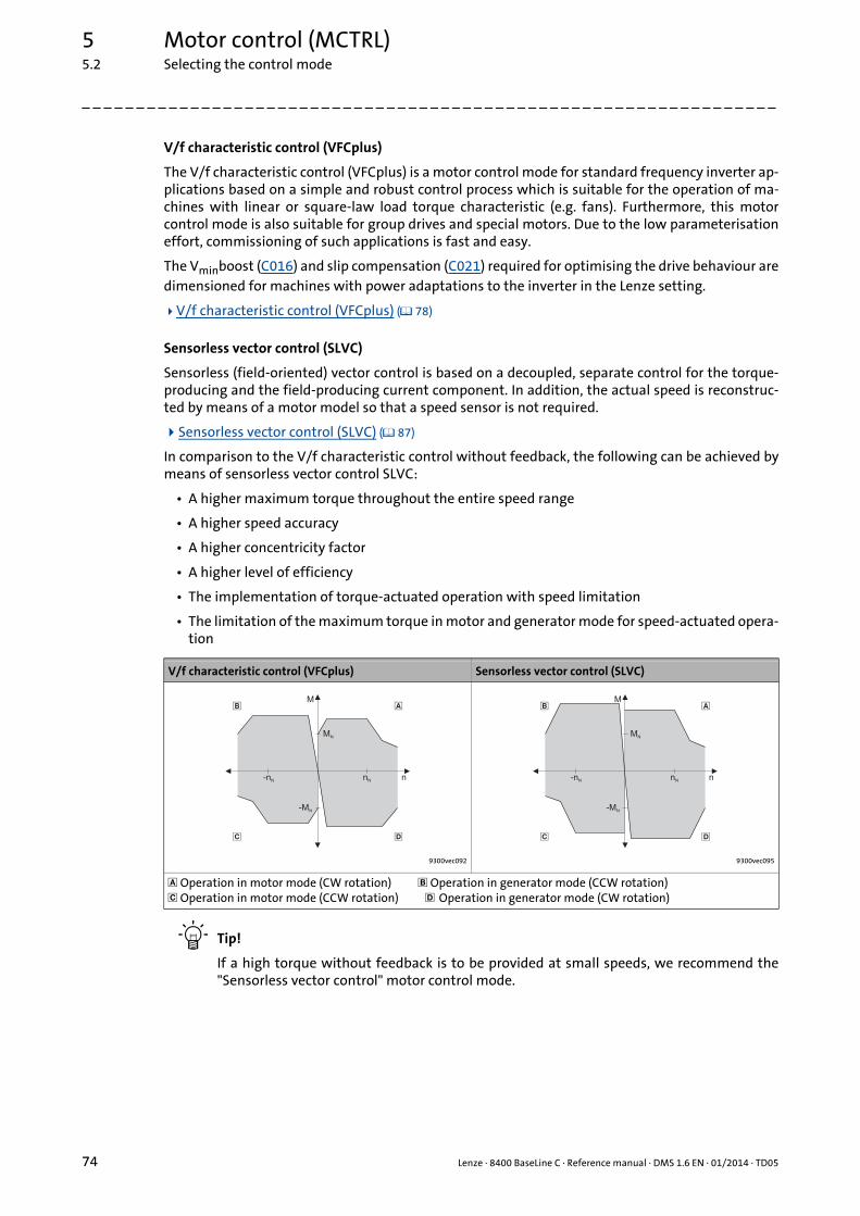
5 Motor control (MCTRL)5.2 Selecting the control mode
74 Lenze · 8400 BaseLine C · Reference manual · DMS 1.6 EN · 01/2014 · TD05
_ _ _ _ _ _ _ _ _ _ _ _ _ _ _ _ _ _ _ _ _ _ _ _ _ _ _ _ _ _ _ _ _ _ _ _ _ _ _ _ _ _ _ _ _ _ _ _ _ _ _ _ _ _ _ _ _ _ _ _ _ _ _ _
V/f characteristic control (VFCplus)
The V/f characteristic control (VFCplus) is a motor control mode for standard frequency inverter ap-plications based on a simple and robust control process which is suitable for the operation of ma-chines with linear or square-law load torque characteristic (e.g. fans). Furthermore, this motorcontrol mode is also suitable for group drives and special motors. Due to the low parameterisationeffort, commissioning of such applications is fast and easy.
The Vminboost (C016) and slip compensation (C021) required for optimising the drive behaviour aredimensioned for machines with power adaptations to the inverter in the Lenze setting.
V/f characteristic control (VFCplus) ( 78)
Sensorless vector control (SLVC)
Sensorless (field-oriented) vector control is based on a decoupled, separate control for the torque-producing and the field-producing current component. In addition, the actual speed is reconstruc-ted by means of a motor model so that a speed sensor is not required.
Sensorless vector control (SLVC) ( 87)
In comparison to the V/f characteristic control without feedback, the following can be achieved bymeans of sensorless vector control SLVC:
• A higher maximum torque throughout the entire speed range
• A higher speed accuracy
• A higher concentricity factor
• A higher level of efficiency
• The implementation of torque-actuated operation with speed limitation
• The limitation of the maximum torque in motor and generator mode for speed-actuated opera-tion
Tip!
If a high torque without feedback is to be provided at small speeds, we recommend the"Sensorless vector control" motor control mode.
V/f characteristic control (VFCplus) Sensorless vector control (SLVC)
9300vec092 9300vec095
Operation in motor mode (CW rotation) Operation in generator mode (CCW rotation) Operation in motor mode (CCW rotation) Operation in generator mode (CW rotation)
��
� �
nN
MN
M
-MN
-nN n
��
� �
nN
MN
M
-MN
-nN n

Lenze · 8400 BaseLine C · Reference manual · DMS 1.6 EN · 01/2014 · TD05 75
5 Motor control (MCTRL)5.2 Selecting the control mode
_ _ _ _ _ _ _ _ _ _ _ _ _ _ _ _ _ _ _ _ _ _ _ _ _ _ _ _ _ _ _ _ _ _ _ _ _ _ _ _ _ _ _ _ _ _ _ _ _ _ _ _ _ _ _ _ _ _ _ _ _ _ _ _
5.2.1 Selection help
To ease the selection of the motor control mode, the two following tables contain recommendati-ons and alternatives to standard applications.
[5-1] Standard applications without speed feedback
Application Recommended Alternatively
Single drives
With constant load VFCplus: V/f linear SLVC
With extremely alternating loads VFCplus: V/f linear SLVC
With high starting duty SLVC VFCplus: V/f linear
Torque limitation SLVC -
With torque limitation (power control) VFCplus: V/f linear SLVC
Three-phase reluctance motor VFCplus: V/f linear -
Three-phase sliding rotor motor VFCplus: V/f linear -
Three-phase AC motors with permanently assigned frequen-cy/voltage characteristic
VFCplus: V/f linear -
Pump and fan drives with quadratic load characteristic VFCplus: V/f quadratic VFCplus or SLVC
Simple hoists VFCplus: V/f linear -
Group drives (several motors connected to controller)
Identical motors and loads VFCplus: V/f linear -
Different motors and/or alternating loads VFCplus: V/f linear -

5 Motor control (MCTRL)5.3 Defining current and speed limits
76 Lenze · 8400 BaseLine C · Reference manual · DMS 1.6 EN · 01/2014 · TD05
_ _ _ _ _ _ _ _ _ _ _ _ _ _ _ _ _ _ _ _ _ _ _ _ _ _ _ _ _ _ _ _ _ _ _ _ _ _ _ _ _ _ _ _ _ _ _ _ _ _ _ _ _ _ _ _ _ _ _ _ _ _ _ _
5.3 Defining current and speed limits
Limitation of the speed setpoint
Parameterising the reference speed in C011 means that the drive must rotate at the set speed if aspeed setpoint of 100% is specified
All speed setpoint selections are provided in % and always refer to the reference speed set in C011.
Tip!
For reasons of achievable resolution and the accuracy involved, the reference speed shouldbe geared to the speed range required for the respective application.
Lenze recommendation: Reference speed (C011) = 1500 ... 3000 rpm
Irrespective of the selected motor control, there are more limitation options:
Current limitation in motor and generator mode
In the various motor control modes, the controller is provided with functions which determine thedynamic behaviour under load and counteract exceedance of the maximum current in motor or ge-nerator mode.
The current limits must be selected depending on
• the permissible maximum current of the motor recommendation: I(Mot)N < 1.5 ... 2.0
• the permissible maximum current of the inverter
• the torque in motor/generator mode required for the application
Parameter Info Lenze setting
Value Unit
C909/1 Max. positive speed 120 %
C909/2 Max. negative speed 120 %
C910/1 Max. positive output frequency 1000 Hz
C910/2 Max. negative output frequency 1000 Hz
Parameter Info Lenze setting
Value Unit
C022 Imax in motor mode 47.00 A
C023 Imax in generator mode• 100 % ≡ Imax in motor mode (C022)
100 %

Lenze · 8400 BaseLine C · Reference manual · DMS 1.6 EN · 01/2014 · TD05 77
5 Motor control (MCTRL)5.3 Defining current and speed limits
_ _ _ _ _ _ _ _ _ _ _ _ _ _ _ _ _ _ _ _ _ _ _ _ _ _ _ _ _ _ _ _ _ _ _ _ _ _ _ _ _ _ _ _ _ _ _ _ _ _ _ _ _ _ _ _ _ _ _ _ _ _ _ _
How to adapt the peak current limitation:
V/f characteristic control (VFCplus):• Reduce the slip compensation with C021.
V/f control (VFCplus + encoder):• Reduce Vminboost inC016.
Sensorless vector control (SLVC):• Reduce the slip compensation with C021.• Reduce the limitation of the torque in motor mode via nTorqueMotLimit_a (C728/1) and
the limitation of the torque in generator mode via nTorqueGenLimit_a (C728/2).
Note!
Highly dynamic applications(that have e.g. too short acceleration/deceleration times or excessively changing loads)
The overcurrent disconnection may respond (fault message OC1), if the setting of the maximum current in motor mode in C022 approximately corresponds to the maximum permissible value of the respective inverter.
Remedies:• Increase of the acceleration and deceleration ramp times• Reduction of the maximum current in motor mode (C022)• Reduction of the maximum current in generator mode (C023)• Adaptation of the indirect peak current limitation (procedure depends on the selected
motor control mode, see below)• Reduction of the reset time of the current limiting controller (C074/1)
Influencing the torque in motor/generator mode
The torque in motor and generator mode can be limited via the nTorqueMotLim and nTorqueGenLim process signal inputs.• If V/f characteristic control (VFCplus) is selected, limitation is indirectly performed via
a so-called Imax controller.
• If sensorless vector control (SLVC) is selected, the limitation has a direct effect on the torque-producing current component.
If keypad control is selected, the nTorqueMotLim and nTorqueGenLim process signals can be parameterised via C728/1...2.

5 Motor control (MCTRL)5.4 V/f characteristic control (VFCplus)
78 Lenze · 8400 BaseLine C · Reference manual · DMS 1.6 EN · 01/2014 · TD05
_ _ _ _ _ _ _ _ _ _ _ _ _ _ _ _ _ _ _ _ _ _ _ _ _ _ _ _ _ _ _ _ _ _ _ _ _ _ _ _ _ _ _ _ _ _ _ _ _ _ _ _ _ _ _ _ _ _ _ _ _ _ _ _
5.4 V/f characteristic control (VFCplus)
In case of the V/f characteristic control (VFCplus), the motor voltage of the inverter is determined bymeans of a linear or quadratic characteristic depending on the field frequency or motor speed to begenerated. The voltage follows a preselected characteristic.
5.4.1 Parameterisation dialog/signal flow
Proceed as follows to open the dialog for parameterising the motor control:
1. »Engineer« Go to the Project view and select the 8400 BaseLine C controller.
2. Go to Workspace and change to the Application parameters tab.
3. Select the motor control from the Overview dialog level in the Motor control list field:• "6: VFCplus: V/f linear" for linear characteristic or• "8: VFCplus: V/f quadr" for square-law characteristic
4. Click the Motor control V/f button to change to the Overview Motor control V/f dialog box.
Stop!
• The following must be observed when operating drives with quadratic V/f characteri-stic: • Please always check whether the corresponding drive is suitable for operation with
a quadratic V/f characteristic! • If your pump drive or fan drive is not suitable for operation with a quadratic V/f
characteristic, you must use either use the V/f characteristic control function with a linear V/f characteristic or the sensorless vector control (SLVC).
• For adjustment, observe the thermal performance of the connected asynchronous motor at low output frequencies.• Usually, standard asynchronous motors with insulation class B can be operated for
a short time with their rated current in the frequency range 0 Hz ≤ f ≤ 25 Hz.• Contact the motor manufacturer to get the exact setting values for the max. per-
missible motor current of self-ventilated motors in the lower speed range.• If you select the quadratic V/f characteristic, we recommend to set a lower Vmin.
• The nameplate data of the motor (at least rated speed and rated frequency) must be entered if, instead of a standard motor, an asynchronous motor is used with the fol-lowing values:• rated frequency ≠ 50 Hz (star) or• rated frequency ≠ 87 Hz (delta) or• number of pole pairs ≠ 2
Note!
When the auto DCB threshold is set (C019) > 0 rpm, there is no torque at the motor shaft in the lower speed range!
Automatic DC-injection braking (Auto-DCB) ( 97)
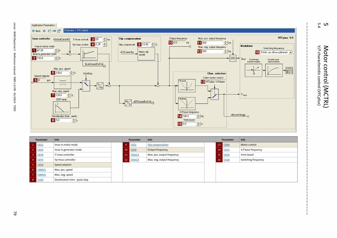
5M
otor control (M
CTRL)
5.4V
/f characteristic con
trol (VFC
plus)
Lenze · 8400 B
aseLine C
· Reference m
anu
al · DM
S 1.6 EN · 01/2014 · TD
0579
_ _ _ _ _ _ _ _ _ _ _ _ _ _ _ _ _ _ _ _ _ _ _ _ _ _ _ _ _ _ _ _ _ _ _ _ _ _ _ _ _ _ _ _ _ _ _ _ _ _ _ _ _ _ _ _ _ _ _ _ _ _ _ _
Parameter Info Parameter Info Parameter Info
1 C022 Imax in motor mode 9 C021 Slip compensation 13 C006 Motor control
2 C023 Imax in generator mode 10 C058 Output frequency 14 C015 V/f base frequency
3 C074 Ti Imax controller 11 C910/1 Max. pos. output frequency 15 C016 Vmin boost
4 C073 Vp Imax controller 12 C910/2 Max. neg. output frequency 16 C018 Switching frequency
5 C050 Speed setpoint
6 C909/1 Max. pos. speed
7 C909/2 Max. neg. speed
8 C105 Deceleration time - quick stop

5 Motor control (MCTRL)5.4 V/f characteristic control (VFCplus)
80 Lenze · 8400 BaseLine C · Reference manual · DMS 1.6 EN · 01/2014 · TD05
_ _ _ _ _ _ _ _ _ _ _ _ _ _ _ _ _ _ _ _ _ _ _ _ _ _ _ _ _ _ _ _ _ _ _ _ _ _ _ _ _ _ _ _ _ _ _ _ _ _ _ _ _ _ _ _ _ _ _ _ _ _ _ _
5.4.2 Basic settings
The "Initial commissioning steps" listed in the table below are sufficient for a simple characteristiccontrol.
• Detailed information on the individual steps can be found in the following subchapters.
Tip!
Information on the optimisation of the control mode and the adaptation to the real appli-cation is provided in the "Optimise control behaviour" chapter. ( 82)
Parameterisable additional functions are described correspondingly in the"Parameterisable additional functions" chapter. ( 92)
5.4.2.1 Defining the V/f characteristic shape
Generally, two different characteristic shapes can be defined:
1. Linear V/f characteristic:For drives for a constant, speed-independent load torque.
2. Quadratic V/f characteristic:For drives with a load torque curve which is quadratic or in relation to speed. Quadratic V/f cha-racteristics are preferred in the case of centrifugal pumps and fan drives.
[5-2] Principle of a linear and quadratic V/f characteristic
The V/f characteristic shape is defined by selecting the corresponding motor control mode in C006:
• "6: VFCplus: V/f linear" for linear characteristic
• "8: VFCplus: V/f quadr" for square-law characteristic
Initial commissioning steps
1. Defining the V/f characteristic shape. ( 80)
2. Defining current limits (Imax controller). ( 81)
0 1
0
100 %
N
nn
Umin
Uout
0 1
0
100 %
N
nn
Umin
Uout
Lenze · 8400 BaseLine C · Reference manual · DMS 1.6 EN · 01/2014 · TD05 81
5 Motor control (MCTRL)5.4 V/f characteristic control (VFCplus)
_ _ _ _ _ _ _ _ _ _ _ _ _ _ _ _ _ _ _ _ _ _ _ _ _ _ _ _ _ _ _ _ _ _ _ _ _ _ _ _ _ _ _ _ _ _ _ _ _ _ _ _ _ _ _ _ _ _ _ _ _ _ _ _
5.4.2.2 Defining current limits (Imax controller)
The V/f characteristic control (VFCplus) is provided with a current limitation control which is decisi-ve for the dynamic behaviour under load and counteracts exceedance of the maximum current inmotor or generator mode. This current limitation control is called Imax control.
• The efficiency (motor current) measured by the Imax control is compared with the current limit value for motor load set in C022 and the current limit value for generator mode set in C023.
• If the current limit values are exceeded, the controller changes its dynamic behaviour.
Motor overload during acceleration
The controller prolongs the acceleration ramp to keep the current on or below the current limit.
Generator overload during deceleration
The controller prolongs the deceleration ramp to keep the current on or below the current limit.
Increasing load with constant speed
• If the motor current limit value is reached:• The controller reduces the effective speed setpoint until a stable working point is set or an
effective speed setpoint of 0 rpm is reached. • If the load is reduced, the controller increases the effective speed setpoint until the setpoint
speed is reached or the load reaches the current limit value again.
• When the generator current limit value is reached:• The controller increases the effective speed setpoint until a stable working point is set or the
maximally permissible speed (C909) or output frequency (C910).• If the load is reduced, the controller reduces the effective speed setpoint until the setpoint
speed is reached or the load reaches the current limit value again.
• If a sudden load is built up at the motor shaft (e.g. drive is blocked), the overcurrent disconnec-tion may respond (fault message OC1).

5 Motor control (MCTRL)5.4 V/f characteristic control (VFCplus)
82 Lenze · 8400 BaseLine C · Reference manual · DMS 1.6 EN · 01/2014 · TD05
_ _ _ _ _ _ _ _ _ _ _ _ _ _ _ _ _ _ _ _ _ _ _ _ _ _ _ _ _ _ _ _ _ _ _ _ _ _ _ _ _ _ _ _ _ _ _ _ _ _ _ _ _ _ _ _ _ _ _ _ _ _ _ _
5.4.3 Optimise control behaviour
The V/f characteristic control (VFCplus) is generally ready for operation. It can be adapted subse-quently by adapting the characteristic and/or the drive behaviour.
Adapting characteristic
For the linear and quadratic characteristic, it is also possible to match its curve to different load pro-files or motors by adapting the V/f base frequency (C015) and the Vmin-boost (C016) .
Adapting the V/f base frequency ( 83)
Adapting the Vmin boost ( 84)
Adapting drive behaviour
• Limitation of the maximum current by a current limitation controller (e.g. to prevent the motor from stalling or to limit to the maximally permissible motor current). Optimising the Imax controller ( 85)
• Adaptation of the field frequency by a load-dependent slip compensation (improved speed ac-curacy for systems without feedback)
Lenze · 8400 BaseLine C · Reference manual · DMS 1.6 EN · 01/2014 · TD05 83
5 Motor control (MCTRL)5.4 V/f characteristic control (VFCplus)
_ _ _ _ _ _ _ _ _ _ _ _ _ _ _ _ _ _ _ _ _ _ _ _ _ _ _ _ _ _ _ _ _ _ _ _ _ _ _ _ _ _ _ _ _ _ _ _ _ _ _ _ _ _ _ _ _ _ _ _ _ _ _ _
5.4.3.1 Adapting the V/f base frequency
The V/f base frequency (C015) determines the slope of the V/f characteristic and has considerableinfluence on the current, torque, and power performance of the motor.
• The setting in C015 applies to all permitted mains voltages.
• Mains fluctuations or fluctuations of the DC-bus voltage (operation in generator mode) do not need to be considered when the V/f base frequency is set. They are automatically compensated for by the internal mains voltage compensation of the device.
• Depending on the setting in C015, it may be required to adapt the reference speed (C011) to tra-verse the entire speed range of the motor.
• In standard applications, the V/f base frequency (C015) is set to the value of the rated motor fre-quency (C089) as a typical value and corresponds to the data of the motor nameplate.
• Reference voltage for the V/f base frequency is the rated motor voltage (C090) according to mo-tor nameplate.
Note!
87-Hz operation
4-pole asynchronous motors which are designed for a rated frequency of f = 50 Hz in star connection can be operated in delta connection when being constantly excited up to f = 87 Hz.• Advantages:
• Higher speed-setting range• 73% higher power output in case of standard motors
• Motor current and motor power increase by the factor .
• The field weakening range starts above 87 Hz.• Generally, this process can also be used with motors which have different numbers of
pole pairs. In case of 2-pole asynchronous motors, the mechanical limit speed must be maintained.
3
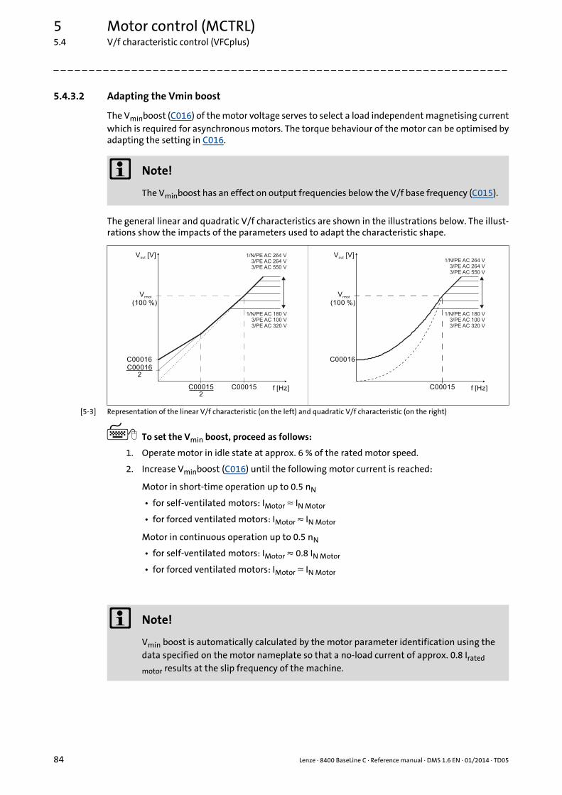
5 Motor control (MCTRL)5.4 V/f characteristic control (VFCplus)
84 Lenze · 8400 BaseLine C · Reference manual · DMS 1.6 EN · 01/2014 · TD05
_ _ _ _ _ _ _ _ _ _ _ _ _ _ _ _ _ _ _ _ _ _ _ _ _ _ _ _ _ _ _ _ _ _ _ _ _ _ _ _ _ _ _ _ _ _ _ _ _ _ _ _ _ _ _ _ _ _ _ _ _ _ _ _
5.4.3.2 Adapting the Vmin boost
The Vminboost (C016) of the motor voltage serves to select a load independent magnetising currentwhich is required for asynchronous motors. The torque behaviour of the motor can be optimised byadapting the setting in C016.
The general linear and quadratic V/f characteristics are shown in the illustrations below. The illust-rations show the impacts of the parameters used to adapt the characteristic shape.
[5-3] Representation of the linear V/f characteristic (on the left) and quadratic V/f characteristic (on the right)
To set the Vmin boost, proceed as follows:
1. Operate motor in idle state at approx. 6 % of the rated motor speed.
2. Increase Vminboost (C016) until the following motor current is reached:
Motor in short-time operation up to 0.5 nN
• for self-ventilated motors: IMotor ≈ IN Motor
• for forced ventilated motors: IMotor ≈ IN Motor
Motor in continuous operation up to 0.5 nN
• for self-ventilated motors: IMotor ≈ 0.8 IN Motor
• for forced ventilated motors: IMotor ≈ IN Motor
Note!
The Vminboost has an effect on output frequencies below the V/f base frequency (C015).
C00015
C00016
C000152
C000162
V [V]out
f [Hz]
V
(100 %)rmot
1/N/PE AC 264 V3/PE AC 264 V3/PE AC 550 V
1/N/PE AC 180 V3/PE AC 100 V3/PE AC 320 V
C00015
C00016
V [V]out
f [Hz]
V
(100 %)rmot
1/N/PE AC 264 V3/PE AC 264 V3/PE AC 550 V
1/N/PE AC 180 V3/PE AC 100 V3/PE AC 320 V
Note!
Vmin boost is automatically calculated by the motor parameter identification using the data specified on the motor nameplate so that a no-load current of approx. 0.8 Irated
motor results at the slip frequency of the machine.

Lenze · 8400 BaseLine C · Reference manual · DMS 1.6 EN · 01/2014 · TD05 85
5 Motor control (MCTRL)5.4 V/f characteristic control (VFCplus)
_ _ _ _ _ _ _ _ _ _ _ _ _ _ _ _ _ _ _ _ _ _ _ _ _ _ _ _ _ _ _ _ _ _ _ _ _ _ _ _ _ _ _ _ _ _ _ _ _ _ _ _ _ _ _ _ _ _ _ _ _ _ _ _
5.4.3.3 Optimising the Imax controller
Using the Lenze setting of the current limitation controller, the drive is stable:
Most applications do not require optimisation.
The setting of the current limitation controller must be adapted if
• power control including great moments of inertia is performed.• Recommendation: Increase of the reset time Ti (C074) of the Imaxcontroller.
• overcurrent errors occur due to load impulses or too high acceleration ramps.• Recommendation: Reduction of the gain Vp (C073) and reset time Ti (C074) of the Imax cont-
roller.
5.4.3.4 Torque limitation
The previous chapter, "Optimising the Imax controller", describes how the drive can be protectedfrom overload. During commissioning, these settings are carried out once and remain unchangedafterwards. However, it is often necessary to limit the torque to a lower value for plant or processreasons.
• To avoid overload in the drive train, the torque in motor mode can be limited via the nTorqueMotLimit_a process input signal, and the torque in generator mode can be limited via the nTorqueGenLimit_a process input signal:
Parameter Info Lenze setting
Value Unit
C073 VFC: Vp Imax controller 0.25
C074 VFC: Ti Imax controller 65 ms
IdentifierDIS code | data type
Information/possible settings
nTorqueMotLimit_aC830/4 | INT
Torque limitation in motor mode• Scaling: 16384 ≡ 100 % Mmax (C057)• Setting range: 0 … +199.9 %• If keypad control is performed: Parameterisable via C728/1.
nTorqueGenLimit_aC830/5 | INT
Torque limitation in generator mode• Scaling: 16384 ≡ 100 % Mmax (C057)• Setting range: -199.9 ... 0 %• If keypad control is performed: Parameterisable via C728/2.
Note!
• The accuracy of the torque limitation is limited because the actual torque (C056/2) is only calculated from the slip speed measured indirectly via the motor current. For this purpose, the correct entry of the motor data is required. Motor selection/Motor data ( 65)
• To avoid instabilities during operation with active slip compensation, the torque limit values are internally processed as absolute values.
• If slip compensation is deactivated (C021 = 0) indirect torque limitation is executed (differential signal between apparent motor current and nTorqueMotLimit_a or nTorqueGenLimit_a). Above the no-load current of the motor, the accuracy of the in-direct torque limitation is limited.

5 Motor control (MCTRL)5.4 V/f characteristic control (VFCplus)
86 Lenze · 8400 BaseLine C · Reference manual · DMS 1.6 EN · 01/2014 · TD05
_ _ _ _ _ _ _ _ _ _ _ _ _ _ _ _ _ _ _ _ _ _ _ _ _ _ _ _ _ _ _ _ _ _ _ _ _ _ _ _ _ _ _ _ _ _ _ _ _ _ _ _ _ _ _ _ _ _ _ _ _ _ _ _
5.4.4 Remedies for undesired drive behaviour
Drive behaviour Remedy
Inadequately smooth running at low speeds, especially in the case of operation with a long motor cable
Automatic motor data identification ( 70)
Problems in case of high starting duty (great mass iner-tia)
Adapting the Vmin boost ( 84)
Drive does not follow the speed setpoint. The current controller intervenes in the set field frequen-cy to limit the controller output current to the maximum current (C0022, C0023). Therefore:
• Prolong acceleration/deceleration time:C012: Acceleration time - main setpointC013: Deceleration time - main setpoint
• Consider a sufficient magnetising time of the motor. Depending on the motor power, the magnetising time amounts to 0.1 ... 0.2 s.
• Increase permissible maximum current:C022: Imax in motor modeC023: Imax in generator mode)
Insufficient speed constancy at high load (setpoint and motor speed are not proportional anymore)
• Increase slip compensation (C021). Important: Unstable drive due to overcompensation!
• With cyclic load impulses (e. g. centrifugal pump), a smooth motor characteristic is achieved by smaller values in C021 (possibly negative values).
Controller cannot follow dynamic processes, i.e. too short acceleration/deceleration times in terms of load ratios.
• Increase the gain of the Imax controller (C073)• Reduce the reset time of the Imax controller(C074)• Increase acceleration time (C012• Increase deceleration time (C013)

Lenze · 8400 BaseLine C · Reference manual · DMS 1.6 EN · 01/2014 · TD05 87
5 Motor control (MCTRL)5.5 Sensorless vector control (SLVC)
_ _ _ _ _ _ _ _ _ _ _ _ _ _ _ _ _ _ _ _ _ _ _ _ _ _ _ _ _ _ _ _ _ _ _ _ _ _ _ _ _ _ _ _ _ _ _ _ _ _ _ _ _ _ _ _ _ _ _ _ _ _ _ _
5.5 Sensorless vector control (SLVC)
Sensorless vector control (SLVC) is based on a better motor current control according to the LenzeFTC process.
In comparison to the V/f characteristic control without feedback, the following can be achieved bymeans of sensorless vector control SLVC:
• A higher maximum torque throughout the entire speed range
• A higher speed accuracy
• A higher concentricity factor
• A higher level of efficiency
• The limitation of the maximum torque in motor and generator mode for speed-actuated opera-tion
Stop!
• The connected motor must not be more than two power classes smaller than the mo-tor assigned to the controller.
• Operation of the sensorless vector control (SLVC) is only permissible for one single dri-ve!
• Operation of the sensorless vector control (SLVC) is not permissible for hoists!• The Lenze setting permits the operation of a power-adapted motor. Optimal operati-
on is only possible if either:• the motor is selected via the Lenze motor catalogue• the motor nameplate data are entered and motor parameter identification is car-
ried out afterwards- or -
• the nameplate data and equivalent circuit data of the motor (motor leakage induc-tance and mutual motor inductance, slip compensation and motor stator resis-tance) are entered manually.
• When you enter the motor nameplate data, take into account the phase connection implemented for the motor (star or delta connection). Only enter the data applying to the selected connection type.• In this context, also observe the instructions in the chapter entitled "Adapting the
V/f base frequency" relating to V/f characteristic control. ( 83)
Note!
Optimal operation of the sensorless vector control (SLVC) can be achieved from a mini-mum speed of approx. 0.5-fold slip speed. At lower speed values below the 0.5-fold slip speed, the maximum torque is reduced.
The maximum field frequency with this motor control mode is 650 Hz.
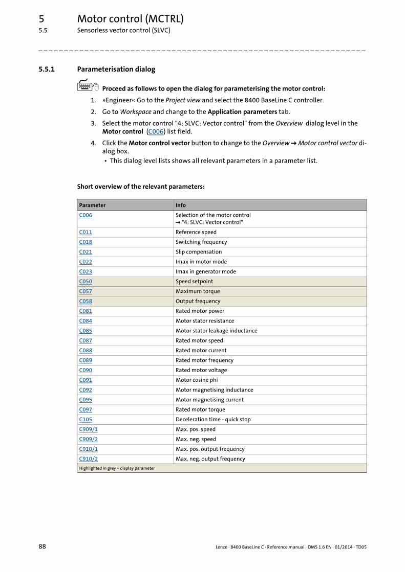
5 Motor control (MCTRL)5.5 Sensorless vector control (SLVC)
88 Lenze · 8400 BaseLine C · Reference manual · DMS 1.6 EN · 01/2014 · TD05
_ _ _ _ _ _ _ _ _ _ _ _ _ _ _ _ _ _ _ _ _ _ _ _ _ _ _ _ _ _ _ _ _ _ _ _ _ _ _ _ _ _ _ _ _ _ _ _ _ _ _ _ _ _ _ _ _ _ _ _ _ _ _ _
5.5.1 Parameterisation dialog
Proceed as follows to open the dialog for parameterising the motor control:
1. »Engineer« Go to the Project view and select the 8400 BaseLine C controller.
2. Go to Workspace and change to the Application parameters tab.
3. Select the motor control "4: SLVC: Vector control" from the Overview dialog level in the Motor control (C006) list field.
4. Click the Motor control vector button to change to the Overview Motor control vector di-alog box.• This dialog level lists shows all relevant parameters in a parameter list.
Short overview of the relevant parameters:
Parameter Info
C006 Selection of the motor control "4: SLVC: Vector control"
C011 Reference speed
C018 Switching frequency
C021 Slip compensation
C022 Imax in motor mode
C023 Imax in generator mode
C050 Speed setpoint
C057 Maximum torque
C058 Output frequency
C081 Rated motor power
C084 Motor stator resistance
C085 Motor stator leakage inductance
C087 Rated motor speed
C088 Rated motor current
C089 Rated motor frequency
C090 Rated motor voltage
C091 Motor cosine phi
C092 Motor magnetising inductance
C095 Motor magnetising current
C097 Rated motor torque
C105 Deceleration time - quick stop
C909/1 Max. pos. speed
C909/2 Max. neg. speed
C910/1 Max. pos. output frequency
C910/2 Max. neg. output frequency
Highlighted in grey = display parameter
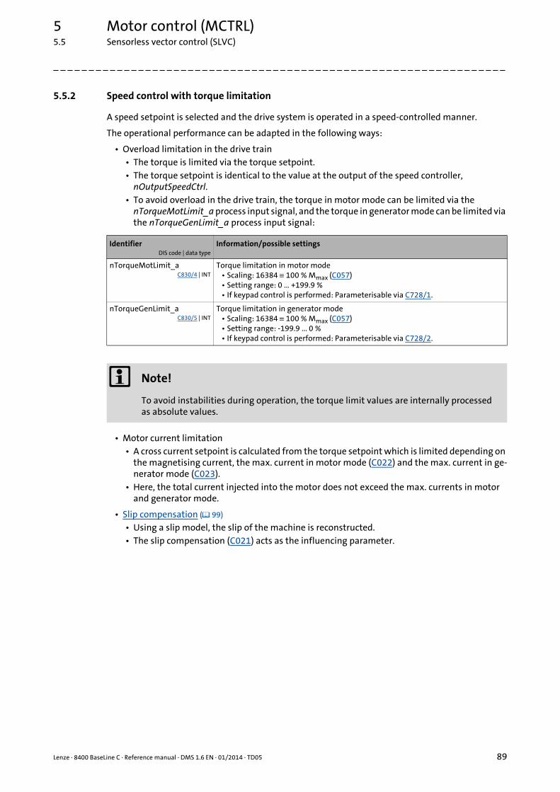
Lenze · 8400 BaseLine C · Reference manual · DMS 1.6 EN · 01/2014 · TD05 89
5 Motor control (MCTRL)5.5 Sensorless vector control (SLVC)
_ _ _ _ _ _ _ _ _ _ _ _ _ _ _ _ _ _ _ _ _ _ _ _ _ _ _ _ _ _ _ _ _ _ _ _ _ _ _ _ _ _ _ _ _ _ _ _ _ _ _ _ _ _ _ _ _ _ _ _ _ _ _ _
5.5.2 Speed control with torque limitation
A speed setpoint is selected and the drive system is operated in a speed-controlled manner.
The operational performance can be adapted in the following ways:
• Overload limitation in the drive train• The torque is limited via the torque setpoint.• The torque setpoint is identical to the value at the output of the speed controller,
nOutputSpeedCtrl.• To avoid overload in the drive train, the torque in motor mode can be limited via the
nTorqueMotLimit_a process input signal, and the torque in generator mode can be limited via the nTorqueGenLimit_a process input signal:
• Motor current limitation• A cross current setpoint is calculated from the torque setpoint which is limited depending on
the magnetising current, the max. current in motor mode (C022) and the max. current in ge-nerator mode (C023).
• Here, the total current injected into the motor does not exceed the max. currents in motor and generator mode.
• Slip compensation ( 99) • Using a slip model, the slip of the machine is reconstructed.• The slip compensation (C021) acts as the influencing parameter.
IdentifierDIS code | data type
Information/possible settings
nTorqueMotLimit_aC830/4 | INT
Torque limitation in motor mode• Scaling: 16384 ≡ 100 % Mmax (C057)• Setting range: 0 … +199.9 %• If keypad control is performed: Parameterisable via C728/1.
nTorqueGenLimit_aC830/5 | INT
Torque limitation in generator mode• Scaling: 16384 ≡ 100 % Mmax (C057)• Setting range: -199.9 ... 0 %• If keypad control is performed: Parameterisable via C728/2.
Note!
To avoid instabilities during operation, the torque limit values are internally processed as absolute values.

5 Motor control (MCTRL)5.5 Sensorless vector control (SLVC)
90 Lenze · 8400 BaseLine C · Reference manual · DMS 1.6 EN · 01/2014 · TD05
_ _ _ _ _ _ _ _ _ _ _ _ _ _ _ _ _ _ _ _ _ _ _ _ _ _ _ _ _ _ _ _ _ _ _ _ _ _ _ _ _ _ _ _ _ _ _ _ _ _ _ _ _ _ _ _ _ _ _ _ _ _ _ _
5.5.3 Basic settings
The following "Initial commissioning steps" must be performed to commission the sensorless vectorcontrol:
Tip!
We recommend to use the flying restart function for connecting/synchronising the inverterto an already rotating drive system.Flying restart function ( 94)
Parameterisable additional functions are described correspondingly in the"Parameterisable additional functions" chapter. ( 92)
5.5.4 Optimise control behaviour
5.5.4.1 Optimising the starting performance after a controller enable
After the controller is enabled, a time delay is cause during the start due to the magnetisation of themotor. If this delay cannot be tolerated for specific applications, the motor must always be operatedin an energised condition.
Procedure without setting a controller inhibit
1. Deactivate the auto-DCB function with C019 = 0.
2. Do not activate the controller inhibit. Instead, stop the drive by selecting a setpoint of 0 or by activating the quick stop function.
Initial commissioning steps
1. Set the motor selection/motor data• When selecting and parameterising the motor, the motor nameplate data and the equivalent circuit di-
agram data are relevant. Detailed information can be found in the "Motor selection/Motor data" chapter. ( 65)
Depending on the motor manufacturer, proceed as follows:
Lenze motor:Selecting a motor from the motor catalogue in the »Engineer«- or -
1.Set the motor nameplate data2.Automatic motor data identification
Third party manufacturer's motor:1.Set the motor nameplate data2.Automatic motor data identification or set known
data of the equivalent circuit diagram manually:C084: Motor stator resistanceC085: Motor stator leakage inductanceC092: Motor magnetising inductanceC095: Motor magnetising current
2. Determine the motor control:C006 = "4: SLVC: Vector control"
3. Set slip compensation (C021). Slip compensation ( 99)

Lenze · 8400 BaseLine C · Reference manual · DMS 1.6 EN · 01/2014 · TD05 91
5 Motor control (MCTRL)5.5 Sensorless vector control (SLVC)
_ _ _ _ _ _ _ _ _ _ _ _ _ _ _ _ _ _ _ _ _ _ _ _ _ _ _ _ _ _ _ _ _ _ _ _ _ _ _ _ _ _ _ _ _ _ _ _ _ _ _ _ _ _ _ _ _ _ _ _ _ _ _ _
5.5.5 Remedies for undesired drive behaviour
Drive behaviour Remedy
Deviation between no-load current and magnetising current or bad speed or torque accuracy.
Adapt the motor magnetising inductance (C092) for no-load operation.
• If the no-load current is greater than the magnetising current (C095) at 0.5-fold rated motor speed, the ma-gnetising inductance must be reduced until the no-load current and the magnetising current have the same values.
• Otherwise, the magnetising inductance must be in-creased.
Tendency of the correction of C092:
PN: Rated motor power
Insufficient speed constancy at high load: Setpoint and motor speed are not proportional anymore.Caution: Overcompensation of the settings mentioned under " Remedy" may result in unstable behaviour!
Via the slip compensation (C021, the speed stability un-der high loads can be affected:
• If nact > nslip, reduce the value in C021• If nact < nslip, increase the value in C021
Unstable control with higher speeds. • Check the setting of the magnetising inductance (C092) by comparing the current consumption in no-load operation with the rated magnetising current (C095)
• Optimise oscillation damping (C234).
"Short circuit" (OC1) error messages at short acceleration time (C012) in proportion to the load (controller cannot follow the dynamic processes).
Increase acceleration time (C012)/deceleration time (C013).
Mechanical resonance at certain speeds. The L_NSet_1 function block masks out those speed ran-ges that include resonance.
Speed variations in no-load operation for speeds > 1/3 rated speed.
Minimise speed oscillations with oscillation damping (C234).
Drive runs unstable. Check set motor data (nameplate data and equivalent circuit diagram data).Motor selection/Motor data ( 65)
Setpoint speed and actual speed differ strongly.
0,37 22 90
C0092
-15 %
+15 %
0
P [kW]N
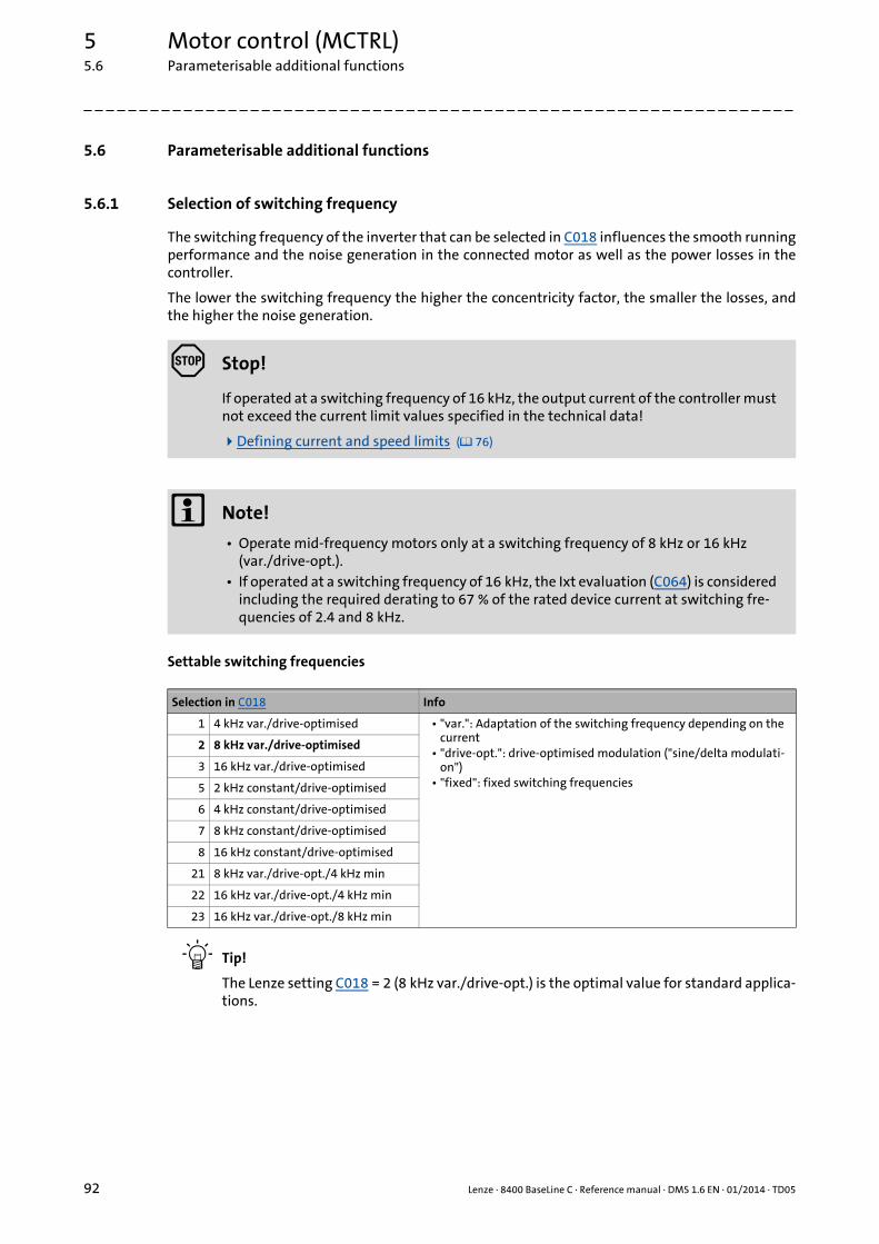
5 Motor control (MCTRL)5.6 Parameterisable additional functions
92 Lenze · 8400 BaseLine C · Reference manual · DMS 1.6 EN · 01/2014 · TD05
_ _ _ _ _ _ _ _ _ _ _ _ _ _ _ _ _ _ _ _ _ _ _ _ _ _ _ _ _ _ _ _ _ _ _ _ _ _ _ _ _ _ _ _ _ _ _ _ _ _ _ _ _ _ _ _ _ _ _ _ _ _ _ _
5.6 Parameterisable additional functions
5.6.1 Selection of switching frequency
The switching frequency of the inverter that can be selected in C018 influences the smooth runningperformance and the noise generation in the connected motor as well as the power losses in thecontroller.
The lower the switching frequency the higher the concentricity factor, the smaller the losses, andthe higher the noise generation.
Settable switching frequencies
Tip!
The Lenze setting C018 = 2 (8 kHz var./drive-opt.) is the optimal value for standard applica-tions.
Stop!
If operated at a switching frequency of 16 kHz, the output current of the controller must not exceed the current limit values specified in the technical data!
Defining current and speed limits ( 76)
Note!
• Operate mid-frequency motors only at a switching frequency of 8 kHz or 16 kHz (var./drive-opt.).
• If operated at a switching frequency of 16 kHz, the Ixt evaluation (C064) is considered including the required derating to 67 % of the rated device current at switching fre-quencies of 2.4 and 8 kHz.
Selection in C018 Info
1 4 kHz var./drive-optimised • "var.": Adaptation of the switching frequency depending on the current
• "drive-opt.": drive-optimised modulation ("sine/delta modulati-on")
• "fixed": fixed switching frequencies
2 8 kHz var./drive-optimised
3 16 kHz var./drive-optimised
5 2 kHz constant/drive-optimised
6 4 kHz constant/drive-optimised
7 8 kHz constant/drive-optimised
8 16 kHz constant/drive-optimised
21 8 kHz var./drive-opt./4 kHz min
22 16 kHz var./drive-opt./4 kHz min
23 16 kHz var./drive-opt./8 kHz min
Lenze · 8400 BaseLine C · Reference manual · DMS 1.6 EN · 01/2014 · TD05 93
5 Motor control (MCTRL)5.6 Parameterisable additional functions
_ _ _ _ _ _ _ _ _ _ _ _ _ _ _ _ _ _ _ _ _ _ _ _ _ _ _ _ _ _ _ _ _ _ _ _ _ _ _ _ _ _ _ _ _ _ _ _ _ _ _ _ _ _ _ _ _ _ _ _ _ _ _ _
Lowering the switching frequency due to high heatsink temperatures
Exceeding the maximally permissible heatsink temperature would lead to an inhibited drive due tothe "Overtemperature" error and a torquelessly coasting motor. Therefore, if the Lenze setting is se-lected, the switching frequency is reduced to the next frequency below when the heatsink tempe-rature has risen to 5 °C below the maximally permissible temperature. After the heatsink has cooleddown, the controller automatically switches to the next frequency above until the set switching fre-quency is reached.
Switching frequency reduction due to high heatsink temperature can be deactivated via C144 . If theswitching frequency reduction is deactivated, the "OH1: Heatsink overtemperature" error messagewill be issued when the maximally permissible heatsink temperature is reached. An "Error" responseis the result and the motor is coasting.
Lowering of the switching frequency depending on the output current
"Variable" switching frequencies can be selected for the controller in C018, where the controller au-tomatically lowers the switching frequency depending on the controller output current. The modu-lation mode will not be changed. The changeover thresholds are included in the rated data of theHardware Manual (the Hardware Manual is available on the CD included in the scope of supply).
When a "fixed" switching frequency is selected, no switching frequency changeover takes place. Incase of fixed frequencies, the controller output current is limited to the permissible value of the cor-responding switching frequency. In case of larger load impulses, the overcurrent interruption maybe activated, to which the controller responds with "Error".
Limiting the maximum output frequency
The maximum output frequency (C910) of the controller is not limited depending on the switchingfrequency. Therefore, adapt the maximum output frequency according to our recommendation:
• At a switching frequency of 4 kHz, for instance, 500 Hz for the maximum output frequency should not be exceeded.
Carry out further measures:
• If required, deactivate the switching frequency changeover by the heatsink temperature via C144.
• If required, ensure that the changeover threshold of the controller output current to the next switching frequency below will not be exceeded. If required, select a constant switching fre-quency in C018.
Display of the current switching frequency
The current switching frequency applied in the controller is displayed in C725.
Operation at an ambient temperature of 45°C
The controller is designed so that operation at an ambient temperature of 45° C without derating ispermissible at a switching frequency of 4 kHz.
Parameter Info Lenze setting
C144 Switching frequency reduction (temp.) 1: On
Maximum output frequency18---Switching frequency≤
5 Motor control (MCTRL)5.6 Parameterisable additional functions
94 Lenze · 8400 BaseLine C · Reference manual · DMS 1.6 EN · 01/2014 · TD05
_ _ _ _ _ _ _ _ _ _ _ _ _ _ _ _ _ _ _ _ _ _ _ _ _ _ _ _ _ _ _ _ _ _ _ _ _ _ _ _ _ _ _ _ _ _ _ _ _ _ _ _ _ _ _ _ _ _ _ _ _ _ _ _
5.6.2 Flying restart function
The flying restart circuit uses a simple model of an asynchronous motor which requires knowledgeof the motor stator resistance RS and the rated motor current.
Tip!
In association with the flying restart function, we recommend to read the information pro-vided in this documentation on the following topic:Automatic DC-injection braking (Auto-DCB) ( 97)
General information
This function serves to activate a mode which is used to "catch" a coasting motor during operationwithout speed feedback. This means that the synchronicity between controller and motor is to beadjusted in such a way that a jerk-free transition to the rotating machines is achieved in the instantof connection.
The drive controller determines the synchronicity by identifying the synchronous field frequency.
Duration
The "catching" process is completed after approx. 1 ... 2 seconds. The duration is influenced by thestarting value. If the field frequency is not known, we recommend the preset starting value of 10 Hz.
Short overview of the relevant parameters:
Note!
• For a correct functioning of the flying restart circuit, we recommend to perform a pa-rameter identification first. Automatic motor data identification ( 70)
• The flying restart function works safely and reliably for drives with great centrifugal masses.
• Do not use the flying restart function if several motors with different centrifugal mas-ses are connected to a controller.
• After the controller is enabled, the motor can start for a short time or reverse when machines with low friction and low mass inertia are used.
• The flying restart function serves to identify max. field frequencies up to ±200 Hz.• When power-adapted standard asynchronous motors are used (rated motor power
approximately corresponds to the rated inverter power), a motor parameter identifi-cation is not required.
Parameter Info Lenze setting
Value Unit
C990 Flying restart fct.: Activation Off
C991 Flying restart fct.: Process -n...+n | Last output frequency
C992 Flying restart: Start frequency 10 Hz
C994 Flying restart fct.: Current 25.00 %
Lenze · 8400 BaseLine C · Reference manual · DMS 1.6 EN · 01/2014 · TD05 95
5 Motor control (MCTRL)5.6 Parameterisable additional functions
_ _ _ _ _ _ _ _ _ _ _ _ _ _ _ _ _ _ _ _ _ _ _ _ _ _ _ _ _ _ _ _ _ _ _ _ _ _ _ _ _ _ _ _ _ _ _ _ _ _ _ _ _ _ _ _ _ _ _ _ _ _ _ _
How to parameterise the flying restart function:
1. Activate the flying restart circuit by selecting "1: On" in C990. • Every time the controller is enabled, a synchronisation to the rotating or standing drive
is carried out.
When the Lenze setting is used, most applications do not require additional controller set-tings.
If additional settings are necessary, proceed as follows:
2. Define the process and hence the speed range/rotational frequency range in C991 which is to be examined by the flying restart circuit.• We recommend the Lenze setting "5: -n...+n | Last output frequency"
3. Adjust setting in C992 if required.
The preset starting frequency which defines the starting point of the flying restart function is optimised for standard motors.• We recommend to define a starting frequency of approximately 20 % of the rated motor
frequency to enable a safe and fast connection to standing drive systems.
4. Set the flying restart current in C994.
We recommend setting a flying restart current of 10 % ... 25 % of the rated motor current.• During a flying restart process, a current is injected into the motor to identify the speed. • Reducing the current causes a reduction of the motor torque during the flying restart
process. A short-time starting action or reversing of the motor is prevented with low flying restart currents.
• An increase of the current improves the robustness of the flying restart function.
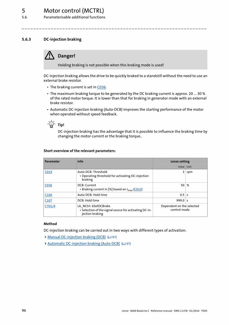
5 Motor control (MCTRL)5.6 Parameterisable additional functions
96 Lenze · 8400 BaseLine C · Reference manual · DMS 1.6 EN · 01/2014 · TD05
_ _ _ _ _ _ _ _ _ _ _ _ _ _ _ _ _ _ _ _ _ _ _ _ _ _ _ _ _ _ _ _ _ _ _ _ _ _ _ _ _ _ _ _ _ _ _ _ _ _ _ _ _ _ _ _ _ _ _ _ _ _ _ _
5.6.3 DC-injection braking
DC-injection braking allows the drive to be quickly braked to a standstill without the need to use anexternal brake resistor.
• The braking current is set in C036.
• The maximum braking torque to be generated by the DC braking current is approx. 20 ... 30 % of the rated motor torque. It is lower than that for braking in generator mode with an external brake resistor.
• Automatic DC-injection braking (Auto-DCB) improves the starting performance of the motor when operated without speed feedback.
Tip!
DC-injection braking has the advantage that it is possible to influence the braking time bychanging the motor current or the braking torque..
Short overview of the relevant parameters:
Method
DC-injection braking can be carried out in two ways with different types of activation:
Manual DC-injection braking (DCB) ( 97)
Automatic DC-injection braking (Auto-DCB) ( 97)
Danger!
Holding braking is not possible when this braking mode is used!
Parameter Info Lenze setting
Value Unit
C019 Auto-DCB: Threshold• Operating threshold for activating DC-injection
braking
3 rpm
C036 DCB: Current• Braking current in [%] based on Imax (C022)
50 %
C106 Auto-DCB: Hold time 0.5 s
C107 DCB: Hold time 999.0 s
C701/4 LA_NCtrl: bSetDCBrake• Selection of the signal source for activating DC-in-
jection braking
Dependent on the selectedcontrol mode
Lenze · 8400 BaseLine C · Reference manual · DMS 1.6 EN · 01/2014 · TD05 97
5 Motor control (MCTRL)5.6 Parameterisable additional functions
_ _ _ _ _ _ _ _ _ _ _ _ _ _ _ _ _ _ _ _ _ _ _ _ _ _ _ _ _ _ _ _ _ _ _ _ _ _ _ _ _ _ _ _ _ _ _ _ _ _ _ _ _ _ _ _ _ _ _ _ _ _ _ _
5.6.3.1 Manual DC-injection braking (DCB)
DC-injection braking can be manually activated via the bSetDCBrake process input.
• For HIGH-active inputs, DC-injection braking is active as long as the signal is at HIGH level.
• After the hold time ((C107) has expired, the controller sets the pulse inhibit (CINH).
Tip!• In the preset "Terminals 0" control mode, DC-injection braking can be manually activa-
ted via the digital input DI3. • In the preset "Terminals 11" control mode, DC-injection braking can be manually activa-
ted via the digital input DI2.
5.6.3.2 Automatic DC-injection braking (Auto-DCB)
"Automatic DC-injection braking" (referred to in the following as "Auto-DCB") can be used if there isa requirement that the drive be isolated from the supply at n ≈ 0.
Function
For understanding the auto-DCB function, it is necessary to distinguish between three different ty-pes of operation:
A. The drive has been enabled and, in the course of operation, the speed setpoint falls below the Auto-DCB threshold.• In case of operation without speed feedback, a braking current (C036) is injected. After the
auto-DCB hold time (C106) has expired, the motor is deenergised via the auto-DCB function, i.e. a controller inhibit (CINH) is set.
B. When the controller is enabled, the drive is at standstill (n = 0). If the enabled drive is to start, the speed setpoint passed via the acceleration ramp must exceed the auto-DCB threshold (C019). Below this threshold, the motor will not be energised.
C. When the controller is enabled, the motor (still) rotates at a speed which is above the auto DCB threshold. If the speed setpoint reached via the acceleration ramp exceeds the auto DCB thres-hold C019), the motor will be energised and the drive will be "caught". Flying restart function ( 94)
How to set the automatic DC-injection braking
1. Set a hold time in C106 > 0 s.• Automatic DC-injection braking is active for the time set.• In case of operation without speed feedback, the braking current set in C036 is injected• After the set hold time has expired, the controller sets a pulse inhibit.
2. Set the operating threshold in C019.• The operating threshold can serve to set a dead band in the setpoint. If DC-injection bra-
king is not to be active then, C106 must be set to a value of "0".
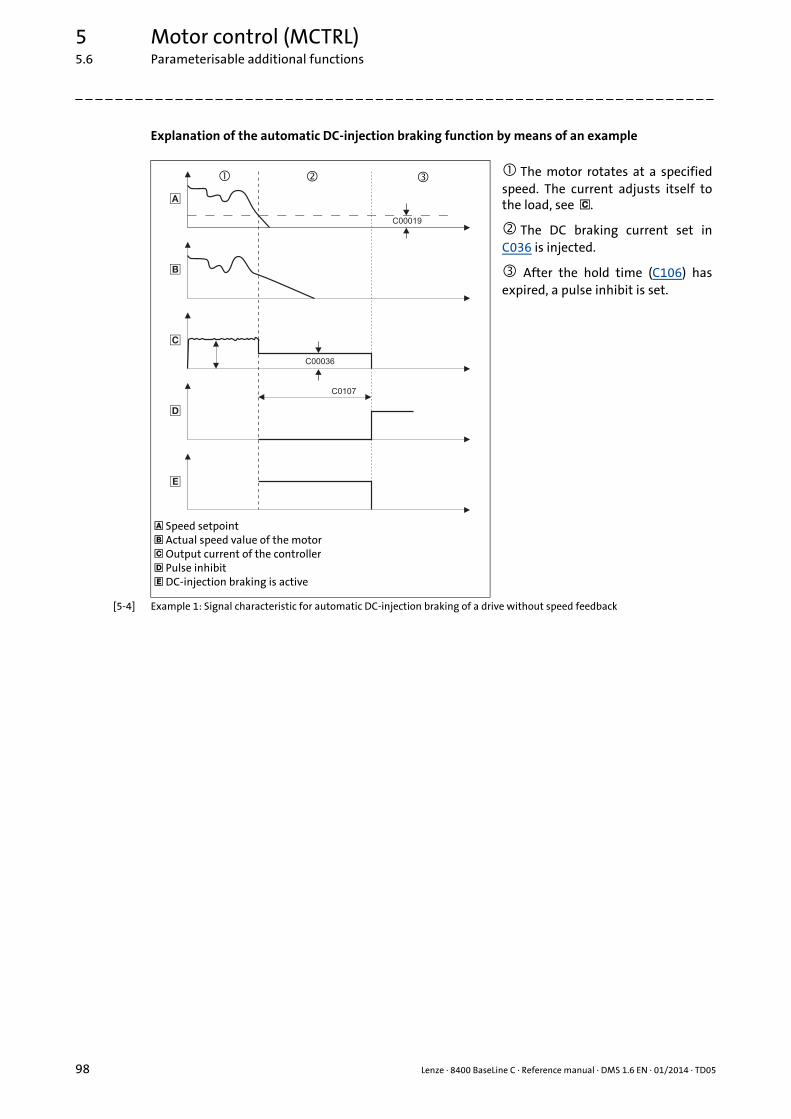
5 Motor control (MCTRL)5.6 Parameterisable additional functions
98 Lenze · 8400 BaseLine C · Reference manual · DMS 1.6 EN · 01/2014 · TD05
_ _ _ _ _ _ _ _ _ _ _ _ _ _ _ _ _ _ _ _ _ _ _ _ _ _ _ _ _ _ _ _ _ _ _ _ _ _ _ _ _ _ _ _ _ _ _ _ _ _ _ _ _ _ _ _ _ _ _ _ _ _ _ _
Explanation of the automatic DC-injection braking function by means of an example
[5-4] Example 1: Signal characteristic for automatic DC-injection braking of a drive without speed feedback
Speed setpoint Actual speed value of the motor Output current of the controller Pulse inhibit DC-injection braking is active
The motor rotates at a specifiedspeed. The current adjusts itself tothe load, see .
The DC braking current set inC036 is injected.
After the hold time (C106) hasexpired, a pulse inhibit is set.
�
�
�
�
�
� �
C0107
C00036
C00019
�
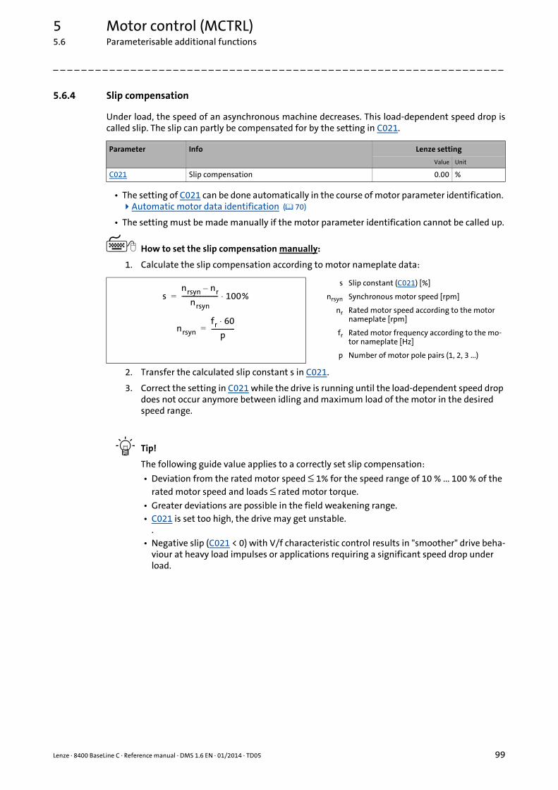
Lenze · 8400 BaseLine C · Reference manual · DMS 1.6 EN · 01/2014 · TD05 99
5 Motor control (MCTRL)5.6 Parameterisable additional functions
_ _ _ _ _ _ _ _ _ _ _ _ _ _ _ _ _ _ _ _ _ _ _ _ _ _ _ _ _ _ _ _ _ _ _ _ _ _ _ _ _ _ _ _ _ _ _ _ _ _ _ _ _ _ _ _ _ _ _ _ _ _ _ _
5.6.4 Slip compensation
Under load, the speed of an asynchronous machine decreases. This load-dependent speed drop iscalled slip. The slip can partly be compensated for by the setting in C021.
• The setting of C021 can be done automatically in the course of motor parameter identification. Automatic motor data identification ( 70)
• The setting must be made manually if the motor parameter identification cannot be called up.
How to set the slip compensation manually:
1. Calculate the slip compensation according to motor nameplate data:
2. Transfer the calculated slip constant s in C021.
3. Correct the setting in C021 while the drive is running until the load-dependent speed drop does not occur anymore between idling and maximum load of the motor in the desired speed range.
Tip!
The following guide value applies to a correctly set slip compensation:
• Deviation from the rated motor speed ≤ 1% for the speed range of 10 % ... 100 % of the rated motor speed and loads ≤ rated motor torque.
• Greater deviations are possible in the field weakening range.• C021 is set too high, the drive may get unstable.
.• Negative slip (C021 < 0) with V/f characteristic control results in "smoother" drive beha-
viour at heavy load impulses or applications requiring a significant speed drop under load.
Parameter Info Lenze setting
Value Unit
C021 Slip compensation 0.00 %
s Slip constant (C021) [%]
nrsyn Synchronous motor speed [rpm]
nr Rated motor speed according to the motor nameplate [rpm]
fr Rated motor frequency according to the mo-tor nameplate [Hz]
p Number of motor pole pairs (1, 2, 3 ...)
snrsyn nr–
nrsyn----------------------- 100%⋅=
nrsynfr 60⋅
p---------------=
5 Motor control (MCTRL)5.6 Parameterisable additional functions
100 Lenze · 8400 BaseLine C · Reference manual · DMS 1.6 EN · 01/2014 · TD05
_ _ _ _ _ _ _ _ _ _ _ _ _ _ _ _ _ _ _ _ _ _ _ _ _ _ _ _ _ _ _ _ _ _ _ _ _ _ _ _ _ _ _ _ _ _ _ _ _ _ _ _ _ _ _ _ _ _ _ _ _ _ _ _
5.6.5 Oscillation damping
Mechanical oscillations are undesirable effects in every process and they may have an adverse effecton the single system components and/or the production output.
Mechanical oscillations in the form of speed oscillations are suppressed by the oscillation dampingfunction.
Oscillation damping is successfully used with
• unloaded motors (no-load oscillations)
• motors whose rated power deviates from the rated power of the controller.• e.g. during operation at high switching frequency including the power derating involved.
• operation with higher-pole motors
• operation with special motors
• compensation of resonance in the drive• At an output frequency of approx. 20 ... 40 Hz, some asynchronous motors can show reso-
nance which causes current and speed variations and thus destabilise the running operation.
How to eliminate speed oscillations:
1. Approach the area where the speed oscillations occur.
2. Reduce the speed oscillations by changing C234 step by step.
3. These can be indicators for smooth running:• Constant motor current characteristic• Reduction of the mechanical oscillations in the bearing seat
Parameter Info Lenze setting
Value Unit
C234 Oscillation damping influence 5.00 %

Lenze · 8400 BaseLine C · Reference manual · DMS 1.6 EN · 01/2014 · TD05 101
5 Motor control (MCTRL)5.7 Braking operation/braking energy management
_ _ _ _ _ _ _ _ _ _ _ _ _ _ _ _ _ _ _ _ _ _ _ _ _ _ _ _ _ _ _ _ _ _ _ _ _ _ _ _ _ _ _ _ _ _ _ _ _ _ _ _ _ _ _ _ _ _ _ _ _ _ _ _
5.7 Braking operation/braking energy management
When electric motors are braked, the kinetic energy of the drive train is fed back into the DC circuitregeneratively. This energy leads to an increase in the DC bus voltage. In order to avoid overvoltagein the DC bus, several different strategies can be used:
• Use of an external brake resistor
• Use of an external brake module(only for inverters with single phase supply)
• Coupling of the inverters in a DC-bus connection(only for inverters with three-phase supply)
• Recovery of regenerative energy with a regenerative module(only for inverters with three-phase supply)
Short overview of the relevant parameters:
Stop!
If the connected brake resistor is smaller than required, the brake chopper can be de-stroyed!• For rated data see hardware manual.• Appropriate protective measures are provided in the "Avoiding thermal overload of
the brake resistor" subchapter. ( 102)
Note!
• We recommend to use the brake chopper (brake transistor) which is integrated into the controller for the braking operation, regardless of the selected motor control.
• For a DC-bus connection with other devices, we recommend to connect the regenera-tive power supply module to terminals +UG and –UG.
• If none of these measures is taken, e.g. the overvoltage deactivation ("OU") may re-spond in case of low deceleration times during regenerative operation. Error messages of the operating system ( 156)
Observe the notes on braking operation in the hardware manual!(see "braking operation" chapter).
All the necessary instructions for the drive controller are stored in electronic form on the data carrier supplied with the 8400 drive controller.
Parameter Info Lenze setting
Value Unit
C173 Mains voltage 3ph 400 V / 1ph 230 V
C174 Reduced brake chopper threshold 0 V
C574 Resp. to brake resist. overtemp. No response

5 Motor control (MCTRL)5.7 Braking operation/braking energy management
102 Lenze · 8400 BaseLine C · Reference manual · DMS 1.6 EN · 01/2014 · TD05
_ _ _ _ _ _ _ _ _ _ _ _ _ _ _ _ _ _ _ _ _ _ _ _ _ _ _ _ _ _ _ _ _ _ _ _ _ _ _ _ _ _ _ _ _ _ _ _ _ _ _ _ _ _ _ _ _ _ _ _ _ _ _ _
5.7.1 Setting the voltage source for braking operation
The voltage threshold for braking operation is set via the mains voltage (C173) and the reduced bra-ke chopper threshold (C174. When this "brake chopper threshold" is exceeded in the DC bus, the en-ergy is dissipated in the DC bus via the brake resistor and the DC-bus voltage is reduced.
• The brake chopper threshold is preset as follows so that it is higher than the specified mains (C173):
• This brake chopper threshold can be reduced by 0 ... 150 V via C174.
Example:
• A 400 V device has a maximum mains voltage of 420 V AC.• Maximum stationary DC-bus voltage: 420 V AC * 1.414 = 594 V DC• C173 has been set with the selection "0" for 400 V AC mains.
• This means that C174 can be set to a maximum of 131 V DC (725 V DC - 594 V DC).
5.7.2 Avoiding thermal overload of the brake resistor
• Parameterisation of an error response in C574 and evaluation of the parameterised error mes-sage within the application or within the machine control system.• See chapter entitled "Brake resistor monitoring (I2xt)". ( 106)
• External interconnection using the thermal contact on the brake resistor (e.g. supply interrupti-on via the mains contactor and activation of the mechanical brakes).
Mains voltage Brake chopper threshold
C173 1-phase 3-phase 1-phase 3-phase
0 1ph 230V 3ph 400V 380V DC 725V DC
1 1ph 230V 3ph 440V 380V DC 35V DC
2 1ph 230V 3ph 480V 380V DC 775V DC
3 1ph 230V 3ph 500V 380V DC 790V DC
Stop!
The brake chopper threshold resulting from C173 and C174 must not exceed the statio-nary DC-bus voltage!
Lenze · 8400 BaseLine C · Reference manual · DMS 1.6 EN · 01/2014 · TD05 103
5 Motor control (MCTRL)5.8 Monitoring
_ _ _ _ _ _ _ _ _ _ _ _ _ _ _ _ _ _ _ _ _ _ _ _ _ _ _ _ _ _ _ _ _ _ _ _ _ _ _ _ _ _ _ _ _ _ _ _ _ _ _ _ _ _ _ _ _ _ _ _ _ _ _ _
5.8 Monitoring
Many monitoring functions that are integrated into the controller can detect errors and thus protectthe device/motor from damage or overload.
• Detailed information on the individual monitoring functions can be found in the following sub-chapters.
Parameterisable responses
If a monitoring function trips, the response set via the corresponding parameter is carried out. Thefollowing responses can be selected:
• "No response": Response/monitoring is deactivated.
• "Fault": Change of the operating status by a pulse inhibit of the power output stage.
• "Warning": Operating status of the controller remains unchanged. Only a message is entered into the logbook of the controller.
Related topics:
Device states ( 53)
Diagnostics & error management ( 145)
Basics on error handling in the controller ( 145)
Error messages of the operating system ( 156)
5.8.1 Device overload monitoring (Ixt)
In C064/1...3 displays the device utilisation (ixt) in [%] in different time intervals:
• If the device utilisation reaches the switch-off threshold set in C123:• The error response set in C604 will be carried out (Lenze setting: "Warning").• The "OC5: Ixt overload" error message will be entered into the logbook.
• A setting of C604 = "0: No Reaction" deactivates the monitoring.
Monitoring Response(Lenze setting)
Parameter
Device overload monitoring (Ixt) Warning C604
Motor load monitoring (I2xt) Warning C606
Brake resistor monitoring (I2xt) No Reaction C574
Mains phase failure monitoring Warning C565
Parameter Info
C064/1 Device utilisation (Ixt)• Maximum value of the pulse utilisation (C064/2)
and permanent utilisation (C064/3).
C064/2 Device utilisation (Ixt) 15s• Pulse utilisation over the last 15 seconds (only for loads >160 %).
C064/3 Device utilisation (Ixt) 3 min• Permanent utilisation over the last 3 minutes.
Highlighted in grey = display parameter

5 Motor control (MCTRL)5.8 Monitoring
104 Lenze · 8400 BaseLine C · Reference manual · DMS 1.6 EN · 01/2014 · TD05
_ _ _ _ _ _ _ _ _ _ _ _ _ _ _ _ _ _ _ _ _ _ _ _ _ _ _ _ _ _ _ _ _ _ _ _ _ _ _ _ _ _ _ _ _ _ _ _ _ _ _ _ _ _ _ _ _ _ _ _ _ _ _ _
5.8.2 Motor load monitoring (I2xt)
The Inverter Drives 8400 are provided with a simple, sensorless, thermal I2xt motor monitoring ofself-ventilated standard motors which is based on a mathematical model.
• In C066 displays the calculated motor load in [%]..
• If the motor load reaches the switch-off threshold set in C120:• The error response set in C606 will be carried out (Lenze setting: "Warning").• The "OC6: I2xt motor overload" error message will be entered into the logbook.
• A setting of C606 = "0: No Reaction" deactivates the monitoring.
Adjustment of the motor utilisation meter
The motor utilisation meter for indicating the motor load in C066 begins to count when the appa-rent motor current (C054) is greater than the set overload threshold (C120).
The overload threshold (C120) is to be set as follows:
• If you reduce C120 starting from the calculated value, the motor utilisation meter will already be counted up before the rated overload threshold is reached.
• If you reduce C120 starting from the calculated value, the motor utilisation meter will already be counted up before the rated overload threshold is reached.
Stop!
The I2xt motor monitoring does not present full motor protection! As the motor utilisa-tion calculated in the thermal motor model is lost after mains switching, for instance the following operating states cannot be measured correctly: • Restarting (after mains switching) of a motor that is already very hot.• Change of the cooling conditions (e.g. cooling air flow interrupted or too warm).
A full motor protection requires additional measures as e.g. the evaluation of tempera-ture sensors that are located directly in the winding or the use of thermal contacts.
Note!
From version 03.04.00, the thermal motor load displayed in C066 can be pre-initialised when the device is connected to the mains, optionally using a fixed value or the value used last at the time when the device was switched off. The desired initialisation is se-lected in C122. In the Lenze setting of C122, the behaviour remains unchanged (no initi-alisation).
Ir : Rated motor current (see nameplate of motor)IN: Rated controller current at a switching frequency of f = 8 kHzC00120
Ir
IN----- 100%⋅=
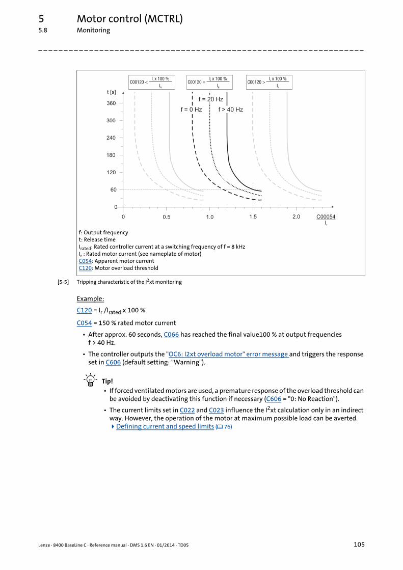
Lenze · 8400 BaseLine C · Reference manual · DMS 1.6 EN · 01/2014 · TD05 105
5 Motor control (MCTRL)5.8 Monitoring
_ _ _ _ _ _ _ _ _ _ _ _ _ _ _ _ _ _ _ _ _ _ _ _ _ _ _ _ _ _ _ _ _ _ _ _ _ _ _ _ _ _ _ _ _ _ _ _ _ _ _ _ _ _ _ _ _ _ _ _ _ _ _ _
[5-5] Tripping characteristic of the I2xt monitoring
Example:
C120 = Ir /Irated x 100 %
C054 = 150 % rated motor current
• After approx. 60 seconds, C066 has reached the final value100 % at output frequencies f > 40 Hz.
• The controller outputs the "OC6: I2xt overload motor" error message and triggers the response set in C606 (default setting: "Warning").
Tip!• If forced ventilated motors are used, a premature response of the overload threshold can
be avoided by deactivating this function if necessary (C606 = "0: No Reaction").
• The current limits set in C022 and C023 influence the I2xt calculation only in an indirect way. However, the operation of the motor at maximum possible load can be averted. Defining current and speed limits ( 76)
f: Output frequencyt: Release timeIrated: Rated controller current at a switching frequency of f = 8 kHzIr : Rated motor current (see nameplate of motor)C054: Apparent motor currentC120: Motor overload threshold
60
180
240
300
360
t [s]
0.50
0
1.0 1.5 2.0 C00054Ir
120
f = 0 Hz
f = 20 Hz
f > 40 Hz
I x 100 %
Ir
N
C00120 <I x 100 %
Ir
N
C00120 =I x 100 %
Ir
N
C00120 >
5 Motor control (MCTRL)5.8 Monitoring
106 Lenze · 8400 BaseLine C · Reference manual · DMS 1.6 EN · 01/2014 · TD05
_ _ _ _ _ _ _ _ _ _ _ _ _ _ _ _ _ _ _ _ _ _ _ _ _ _ _ _ _ _ _ _ _ _ _ _ _ _ _ _ _ _ _ _ _ _ _ _ _ _ _ _ _ _ _ _ _ _ _ _ _ _ _ _
5.8.3 Brake resistor monitoring (I2xt)
Due to the converted braking power, the brake resistor is thermally stressed and can even be ther-mally destroyed by excessive braking power.
The monitoring of the I2xt utilisation of the controller serves to protect the brake resistor. It acts inproportion to the converted braking power.
• If the I2xt utilisation reaches a permanently set switch-off threshold:• The error response set in C574 takes place.• The "OC12: I2xt brake resistor overload" error message is entered into the logbook.
• If the system is dimensioned correctly, the monitoring mode should not respond.
• If the DC-bus voltage exceeds the overvoltage threshold due to a braking energy that is too high, the monitoring for overvoltage in the DC bus is activated ("OU: DC-bus overvoltage" error mes-sage).
Related topics:
Braking operation/braking energy management ( 101)
Danger!
In the Lenze setting ((C574 = "0: No Reaction") the response of the monitoring function does not stop the braking operation!
In particular for applications such as hoists or applications with a DC-bus connection, it must be checked if a stopping of the braking operation due to the setting of C574 = "1: Fault" is permissible.
Stop!
Implement appropriate protective measures against thermal overload of the brake resis-tor!
Examples:• Parameterisation of an error response in C574 and evaluation of the parameterised
error message within the application or within the machine control system.• Interruption of the mains supply by means of the temperature contact at the brake re-
sistor and a simultaneous activation of the mechanical brake.

Lenze · 8400 BaseLine C · Reference manual · DMS 1.6 EN · 01/2014 · TD05 107
5 Motor control (MCTRL)5.8 Monitoring
_ _ _ _ _ _ _ _ _ _ _ _ _ _ _ _ _ _ _ _ _ _ _ _ _ _ _ _ _ _ _ _ _ _ _ _ _ _ _ _ _ _ _ _ _ _ _ _ _ _ _ _ _ _ _ _ _ _ _ _ _ _ _ _
5.8.4 Mains phase failure monitoring
The drive controller has a simple mains-phase failure detection function with which a mains phasefailure can be detected under load.
• In the case of power-adapted machines, approx. 50 % of the rated motor power must be excee-ded so that a main-phase failure can be detected.
• If the mains phase failure monitoring is tripped:• The error response set in C565 will be carried out (Lenze setting: "Warning").• The "Su02: Mains voltage switched-off" error message is entered into the logbook.
Stop!
Under load, the mains input of a three-phase controller can be destroyed if the device is only supplied by two phases (e.g. if a mains phase fails).
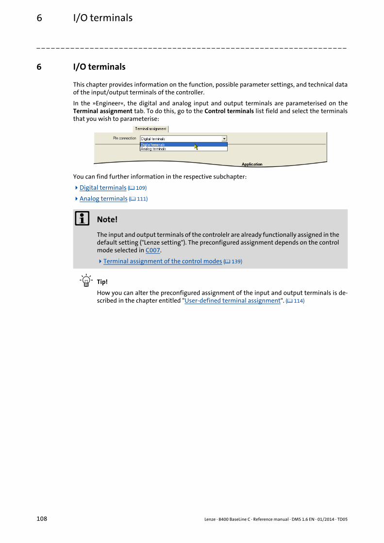
6 I/O terminals
108 Lenze · 8400 BaseLine C · Reference manual · DMS 1.6 EN · 01/2014 · TD05
_ _ _ _ _ _ _ _ _ _ _ _ _ _ _ _ _ _ _ _ _ _ _ _ _ _ _ _ _ _ _ _ _ _ _ _ _ _ _ _ _ _ _ _ _ _ _ _ _ _ _ _ _ _ _ _ _ _ _ _ _ _ _ _
6 I/O terminals
This chapter provides information on the function, possible parameter settings, and technical dataof the input/output terminals of the controller.
In the »Engineer«, the digital and analog input and output terminals are parameterised on theTerminal assignment tab. To do this, go to the Control terminals list field and select the terminalsthat you wish to parameterise:
You can find further information in the respective subchapter:
Digital terminals ( 109)
Analog terminals ( 111)
Tip!
How you can alter the preconfigured assignment of the input and output terminals is de-scribed in the chapter entitled "User-defined terminal assignment". ( 114)
Note!
The input and output terminals of the controlelr are already functionally assigned in the default setting ("Lenze setting"). The preconfigured assignment depends on the control mode selected in C007.
Terminal assignment of the control modes ( 139)

Lenze · 8400 BaseLine C · Reference manual · DMS 1.6 EN · 01/2014 · TD05 109
6 I/O terminals6.1 Digital terminals
_ _ _ _ _ _ _ _ _ _ _ _ _ _ _ _ _ _ _ _ _ _ _ _ _ _ _ _ _ _ _ _ _ _ _ _ _ _ _ _ _ _ _ _ _ _ _ _ _ _ _ _ _ _ _ _ _ _ _ _ _ _ _ _
6.1 Digital terminals
Digital input terminals
The drive controller has
• four parameterisable input terminals (DI1 ... DI4) for detecting digital signals.
• one RFR control input for controller enable.
Digital output terminals
The drive controller has
• a parameterisable output terminal (DO1) for outputting digital signals,
• a relay output (NO/COM).
Note!
Initialisation behaviour:• After mains switching up to the start of the application
• the digital output remains set to FALSE.• the switching contact of the relay (NO/COM) remains open.
Exception handling:• In the event of a critical exception in the application (e.g. reset), the digital output is
set to FALSE.
Switching cycle diagnostics of the relay:• A reference for evaluating the wear limit can be obtained via the number of switching
cycles of the relay displayed in C177/2.

6 I/O terminals6.1 Digital terminals
110 Lenze · 8400 BaseLine C · Reference manual · DMS 1.6 EN · 01/2014 · TD05
_ _ _ _ _ _ _ _ _ _ _ _ _ _ _ _ _ _ _ _ _ _ _ _ _ _ _ _ _ _ _ _ _ _ _ _ _ _ _ _ _ _ _ _ _ _ _ _ _ _ _ _ _ _ _ _ _ _ _ _ _ _ _ _
Parameterisation dialog in the »Engineer«
Short overview of parameters for the digital terminals:
Button Function
Indicates the polarity of the input is HIGH active.The polarity can be changed from HIGH active to LOW active by clicking on this button.
Indicates that the polarity of the input is LOW active.The polarity can be changed from LOW active to HIGH active by clicking on this button.
Open the parameterising dialog for assigning application inputs to the digital input. Changing the terminal assignment with the »Engineer« ( 116)
Parameter Info Lenze setting
Value Unit
Digital inputs DI1 ... DI5
C114 DIx: Polarity Bit coded
C443/1 DIx: Terminal level -
C443/2 DIx: Output level (to the application) -
Digital output DO1 / relay output
C118 DOx: Inversion Bit coded
C444/1 DOx: Input level (from the application) -
C444/2 DOx: Terminal level -
Digital outputs - terminal configuration
C621/1 LS_DigitalOutput:bRelay 50: LA_nCtrl_bDriveFail
C621/2 LS_DigitalOutput:bOut1 51: LA_nCtrl_bDriveReady
Highlighted in grey = display parameter

Lenze · 8400 BaseLine C · Reference manual · DMS 1.6 EN · 01/2014 · TD05 111
6 I/O terminals6.2 Analog terminals
_ _ _ _ _ _ _ _ _ _ _ _ _ _ _ _ _ _ _ _ _ _ _ _ _ _ _ _ _ _ _ _ _ _ _ _ _ _ _ _ _ _ _ _ _ _ _ _ _ _ _ _ _ _ _ _ _ _ _ _ _ _ _ _
6.2 Analog terminals
The controller is provided with an analog input for detecting a voltage signal. The voltage signal canbe e.g. an analog speed setpoint selection or the signal of an external sensor (temperature, pressure,etc.).
• Possible voltage ranges:• 0 ... +10 V (Lenze setting)• 0 ... +5 V• 1 ... +5 V
• An external 250-Ω load resistor and a respective parameter setting allow to implement a cur-rent loop:• 0 ... 20 mA, without open-circuit monitoring• 4 ... 20 mA, with open-circuit monitoring
Parameterisation dialog in the »Engineer«:
Note!
To avoid undefined states, free input terminals of the controller must be assigned as well, e.g. by applying 0 V to the terminal.
Button Function
Parameterising analog input ( 112)
Open the parameterising dialog for assigning application inputs to the analog input. Changing the terminal assignment with the »Engineer« ( 116)
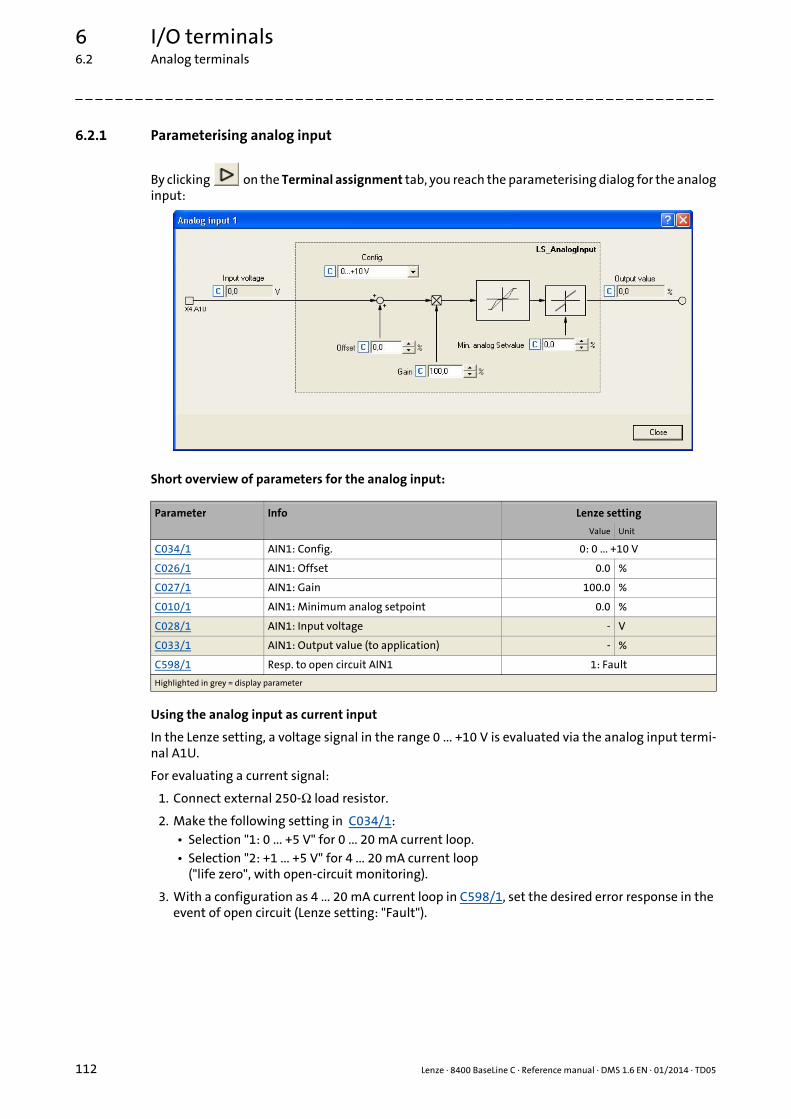
6 I/O terminals6.2 Analog terminals
112 Lenze · 8400 BaseLine C · Reference manual · DMS 1.6 EN · 01/2014 · TD05
_ _ _ _ _ _ _ _ _ _ _ _ _ _ _ _ _ _ _ _ _ _ _ _ _ _ _ _ _ _ _ _ _ _ _ _ _ _ _ _ _ _ _ _ _ _ _ _ _ _ _ _ _ _ _ _ _ _ _ _ _ _ _ _
6.2.1 Parameterising analog input
By clicking on the Terminal assignment tab, you reach the parameterising dialog for the analoginput:
Short overview of parameters for the analog input:
Using the analog input as current input
In the Lenze setting, a voltage signal in the range 0 ... +10 V is evaluated via the analog input termi-nal A1U.
For evaluating a current signal:
1. Connect external 250-Ω load resistor.
2. Make the following setting in C034/1:• Selection "1: 0 ... +5 V" for 0 ... 20 mA current loop.• Selection "2: +1 ... +5 V" for 4 ... 20 mA current loop
("life zero", with open-circuit monitoring).
3. With a configuration as 4 ... 20 mA current loop in C598/1, set the desired error response in the event of open circuit (Lenze setting: "Fault").
Parameter Info Lenze setting
Value Unit
C034/1 AIN1: Config. 0: 0 ... +10 V
C026/1 AIN1: Offset 0.0 %
C027/1 AIN1: Gain 100.0 %
C010/1 AIN1: Minimum analog setpoint 0.0 %
C028/1 AIN1: Input voltage - V
C033/1 AIN1: Output value (to application) - %
C598/1 Resp. to open circuit AIN1 1: Fault
Highlighted in grey = display parameter

Lenze · 8400 BaseLine C · Reference manual · DMS 1.6 EN · 01/2014 · TD05 113
6 I/O terminals6.2 Analog terminals
_ _ _ _ _ _ _ _ _ _ _ _ _ _ _ _ _ _ _ _ _ _ _ _ _ _ _ _ _ _ _ _ _ _ _ _ _ _ _ _ _ _ _ _ _ _ _ _ _ _ _ _ _ _ _ _ _ _ _ _ _ _ _ _
Minimum and maximum output speed
The speed range required for the application results from the selected reference speed (C011) andthe minimum analog setpoint (C010):
• The reference speed set in C011 is reached at a speed setpoint selection of 100 %.• All speed setpoint selections are provided in % and always refer to the reference speed set in
C011 (independent of the setpoint source).
• The speed set in C010 corresponds to the minimum speed if the speed setpoint has been selec-ted via the analog input (Lenze setting) and a voltage of 0 V is applied to the X4/A1U input ter-minal.
[6-1] Relation between the selected setpoint and minimum and maximum output speed
0 V
n
10 V
100 % = C00011
C00010

6 I/O terminals6.3 User-defined terminal assignment
114 Lenze · 8400 BaseLine C · Reference manual · DMS 1.6 EN · 01/2014 · TD05
_ _ _ _ _ _ _ _ _ _ _ _ _ _ _ _ _ _ _ _ _ _ _ _ _ _ _ _ _ _ _ _ _ _ _ _ _ _ _ _ _ _ _ _ _ _ _ _ _ _ _ _ _ _ _ _ _ _ _ _ _ _ _ _
6.3 User-defined terminal assignment
In order to individually adapt the preconfigured assignment of the input/output terminals to yourapplication, you can choose one of the following procedures:
A. In the »Engineer«:• Change the terminal assignment on the Terminal assignment tab.• Change the signal assignment on the Application Parameters tab, on the dialog level
Overview Signal flow.
B. In the »Engineer« or with the keypad:• Change the parameters for signal configuration in the parameters list.
Tip!
First set a suitable Lenze configuration by selecting a corresponding control mode in C007.
We recommend using the »Engineer« for the implementation of comprehensive user-defi-ned drive solutions.
Note!
If you change the preconfigured assignment of the input/output terminals, the terminal assignment will be a user-defined one. In C007, control mode "0: Interconnection chan-ged" will be shown.

Lenze · 8400 BaseLine C · Reference manual · DMS 1.6 EN · 01/2014 · TD05 115
6 I/O terminals6.3 User-defined terminal assignment
_ _ _ _ _ _ _ _ _ _ _ _ _ _ _ _ _ _ _ _ _ _ _ _ _ _ _ _ _ _ _ _ _ _ _ _ _ _ _ _ _ _ _ _ _ _ _ _ _ _ _ _ _ _ _ _ _ _ _ _ _ _ _ _
6.3.1 Source-destination principle
The I/O configuration of the input and output signals is carried out according to the source/desti-nation principle:
• A connection always has a direction and therefore always has a source and a target.
• The input signals of the application are logically linked via configuration parameters to the out-put signals of system blocks which represent the device input terminals.
• The inputs of system blocks that represent the device output terminals are logically to output signals of the application via configuration parameters.
The following graphic illustrates the source/destination principle:
[6-2] Source-destination principle
Note the following:
• A device input terminal can be logically linked to several inputs of the application.
• Each input of the application can only be logically linked to one input signal.
• An output of the application can be logically linked to several device output terminals.
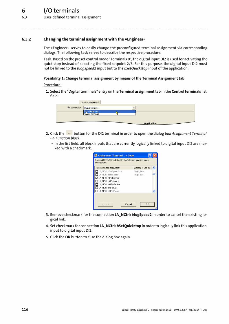
6 I/O terminals6.3 User-defined terminal assignment
116 Lenze · 8400 BaseLine C · Reference manual · DMS 1.6 EN · 01/2014 · TD05
_ _ _ _ _ _ _ _ _ _ _ _ _ _ _ _ _ _ _ _ _ _ _ _ _ _ _ _ _ _ _ _ _ _ _ _ _ _ _ _ _ _ _ _ _ _ _ _ _ _ _ _ _ _ _ _ _ _ _ _ _ _ _ _
6.3.2 Changing the terminal assignment with the »Engineer«
The »Engineer« serves to easily change the preconfigured terminal assignment via correspondingdialogs. The following task serves to describe the respective procedure.
Task: Based on the preset control mode "Terminals 0", the digital input DI2 is used for activating thequick stop instead of selecting the fixed setpoint 2/3. For this purpose, the digital input DI2 mustnot be linked to the bJogSpeed2 input but to the bSetQuickstop input of the application.
Possibility 1: Change terminal assignment by means of the Terminal Assignment tab
Procedure:
1. Select the "Digital terminals" entry on the Terminal assignment tab in the Control terminals list field:
2. Click the button for the DI2 terminal in order to open the dialog box Assignment Terminal --> Function block.• In the list field, all block inputs that are currently logically linked to digital input DI2 are mar-
ked with a checkmark:
3. Remove checkmark for the connection LA_NCtrl: bJogSpeed2 in order to cancel the existing lo-gical link.
4. Set checkmark for connection LA_NCtrl: bSetQuickstop in order to logically link this application input to digital input DI2.
5. Click the OK button to clise the dialog box again.
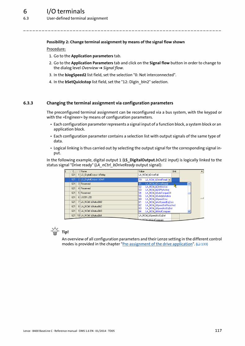
Lenze · 8400 BaseLine C · Reference manual · DMS 1.6 EN · 01/2014 · TD05 117
6 I/O terminals6.3 User-defined terminal assignment
_ _ _ _ _ _ _ _ _ _ _ _ _ _ _ _ _ _ _ _ _ _ _ _ _ _ _ _ _ _ _ _ _ _ _ _ _ _ _ _ _ _ _ _ _ _ _ _ _ _ _ _ _ _ _ _ _ _ _ _ _ _ _ _
Possibility 2: Change terminal assignment by means of the signal flow shown
Procedure:
1. Go to the Application parameters tab.
2. Go to the Application Parameters tab and click on the Signal flow button in order to change to the dialog level Overview Signal flow.
3. In the bJogSpeed2 list field, set the selection "0: Not interconnected".
4. In the bSetQuickstop list field, set the "12: DigIn_bIn2" selection.
6.3.3 Changing the terminal assignment via configuration parameters
The preconfigured terminal assignment can be reconfigured via a bus system, with the keypad orwith the »Engineer« by means of configuration parameters.
• Each configuration parameter represents a signal input of a function block, a system block or an application block.
• Each configuration parameter contains a selection list with output signals of the same type of data.
• Logical linking is thus carried out by selecting the output signal for the corresponding signal in-put.
In the following example, digital output 1 (LS_DigitalOutput.bOut1 input) is logically linked to thestatus signal "Drive ready" (LA_nCtrl_bDriveReady output signal):
Tip!
An overview of all configuration parameters and their Lenze setting in the different controlmodes is provided in the chapter "Pre-assignment of the drive application". ( 133)

6 I/O terminals6.3 User-defined terminal assignment
118 Lenze · 8400 BaseLine C · Reference manual · DMS 1.6 EN · 01/2014 · TD05
_ _ _ _ _ _ _ _ _ _ _ _ _ _ _ _ _ _ _ _ _ _ _ _ _ _ _ _ _ _ _ _ _ _ _ _ _ _ _ _ _ _ _ _ _ _ _ _ _ _ _ _ _ _ _ _ _ _ _ _ _ _ _ _
Example
Task: Based on the preset control mode "Terminals 0", the digital input DI2 is used for activating thequick stop instead of selecting the fixed setpoint 2/3. For this purpose, the digital input DI2 mustnot be linked to the bJogSpeed2 input but to the bSetQuickstop input of the application.
Procedure:
1. Change the setting of the configuration parameter LA_NCtrl: bSetQuickstop (C701/3) which re-presents the logical link of the bSetQuickstop application input: "0: Not connected" "12: DigIn_bIn2"
2. Change the setting of the configuration parameter LA_NCtrl: bJogSpeed2 (C701/7) which rep-resents the logical link of the bJogSpeed2 application input: "12: DigIn_bIn2" "0: Not connec-ted"
[6-3] Example: Changing the terminal assignment via configuration parameters
Tip!
The example shows, for each input of the application, the associated configuration para-meter (C700/x or C701/x) is only allowed to contain one source that you enter.
Related topics:
Pre-assignment of the drive application ( 133)
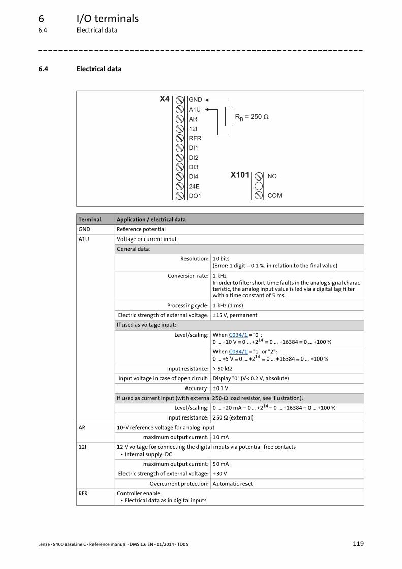
Lenze · 8400 BaseLine C · Reference manual · DMS 1.6 EN · 01/2014 · TD05 119
6 I/O terminals6.4 Electrical data
_ _ _ _ _ _ _ _ _ _ _ _ _ _ _ _ _ _ _ _ _ _ _ _ _ _ _ _ _ _ _ _ _ _ _ _ _ _ _ _ _ _ _ _ _ _ _ _ _ _ _ _ _ _ _ _ _ _ _ _ _ _ _ _
6.4 Electrical data
Terminal Application / electrical data
GND Reference potential
A1U Voltage or current input
General data:
Resolution: 10 bits(Error: 1 digit ≡ 0.1 %, in relation to the final value)
Conversion rate: 1 kHzIn order to filter short-time faults in the analog signal charac-teristic, the analog input value is led via a digital lag filter with a time constant of 5 ms.
Processing cycle: 1 kHz (1 ms)
Electric strength of external voltage: ±15 V, permanent
If used as voltage input:
Level/scaling: When C034/1 = "0":0 ... +10 V ≡ 0 ... +214 ≡ 0 ... +16384 ≡ 0 ... +100 %
When C034/1 = "1" or "2":0 ... +5 V ≡ 0 ... +214 ≡ 0 ... +16384 ≡ 0 ... +100 %
Input resistance: > 50 kΩ
Input voltage in case of open circuit: Display "0" (V< 0.2 V, absolute)
Accuracy: ±0.1 V
If used as current input (with external 250-Ω load resistor; see illustration):
Level/scaling: 0 ... +20 mA ≡ 0 ... +214 ≡ 0 ... +16384 ≡ 0 ... +100 %
Input resistance: 250 Ω (external)
AR 10-V reference voltage for analog input
maximum output current: 10 mA
12I 12 V voltage for connecting the digital inputs via potential-free contacts• Internal supply: DC
maximum output current: 50 mA
Electric strength of external voltage: +30 V
Overcurrent protection: Automatic reset
RFR Controller enable• Electrical data as in digital inputs
X4 GND
A1U
AR
12I
RFR
DI1
DI2
DI3
DI4
24E
DO1
R = 250B �
X101 NO
COM
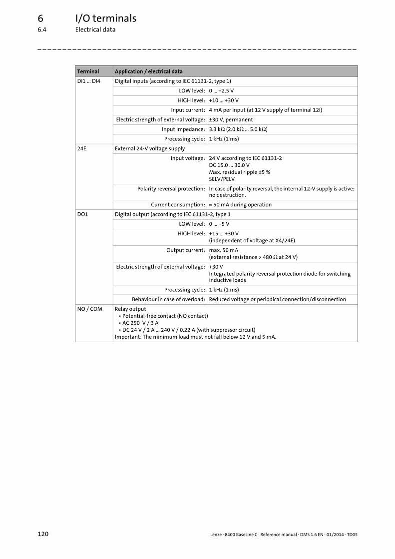
6 I/O terminals6.4 Electrical data
120 Lenze · 8400 BaseLine C · Reference manual · DMS 1.6 EN · 01/2014 · TD05
_ _ _ _ _ _ _ _ _ _ _ _ _ _ _ _ _ _ _ _ _ _ _ _ _ _ _ _ _ _ _ _ _ _ _ _ _ _ _ _ _ _ _ _ _ _ _ _ _ _ _ _ _ _ _ _ _ _ _ _ _ _ _ _
DI1 ... DI4 Digital inputs (according to IEC 61131-2, type 1)
LOW level: 0 ... +2.5 V
HIGH level: +10 ... +30 V
Input current: 4 mA per input (at 12 V supply of terminal 12I)
Electric strength of external voltage: ±30 V, permanent
Input impedance: 3.3 kΩ (2.0 kΩ ... 5.0 kΩ)
Processing cycle: 1 kHz (1 ms)
24E External 24-V voltage supply
Input voltage: 24 V according to IEC 61131-2DC 15.0 ... 30.0 VMax. residual ripple ±5 %SELV/PELV
Polarity reversal protection: In case of polarity reversal, the internal 12-V supply is active; no destruction.
Current consumption: ≈ 50 mA during operation
DO1 Digital output (according to IEC 61131-2, type 1
LOW level: 0 ... +5 V
HIGH level: +15 ... +30 V(independent of voltage at X4/24E)
Output current: max. 50 mA(external resistance > 480 Ω at 24 V)
Electric strength of external voltage: +30 VIntegrated polarity reversal protection diode for switching inductive loads
Processing cycle: 1 kHz (1 ms)
Behaviour in case of overload: Reduced voltage or periodical connection/disconnection
NO / COM Relay output• Potential-free contact (NO contact)• AC 250 V / 3 A• DC 24 V / 2 A ... 240 V / 0.22 A (with suppressor circuit)
Important: The minimum load must not fall below 12 V and 5 mA.
Terminal Application / electrical data

Lenze · 8400 BaseLine C · Reference manual · DMS 1.6 EN · 01/2014 · TD05 121
7 Drive application
_ _ _ _ _ _ _ _ _ _ _ _ _ _ _ _ _ _ _ _ _ _ _ _ _ _ _ _ _ _ _ _ _ _ _ _ _ _ _ _ _ _ _ _ _ _ _ _ _ _ _ _ _ _ _ _ _ _ _ _ _ _ _ _
7 Drive application
The "actuating drive speed" application provided in the 8400 BaseLine C controller is a drive solutionequipped with Lenze's experience and know-how in which function and system blocks interconnec-ted to a signal flow clearly show the basis for implementing typical drive tasks.
The application serves to solve speed-controlled drive tasks, e.g. conveyor drives (interconnected),extruders, test benches, vibrators, travelling drives, presses, machining tools, dosing systems.
Brief description of the features
• Pre-configured control modes for terminals and bus control (with predefined process data con-nection to the fieldbus)
• Free configuration of input and output signals
• Offset and gain of the main setpoint (if defined via analog input)
• Up to 3 fixed setpoints for speed
• Adjustable setpoint ramp times
• Linear or S-shaped ramp
• Quick stop (QSP) with adjustable ramp time
• Connectable motor potentiometer function (as alternative setpoint source)
• Connectable process controller (PID controller) with various operating modes
• Load monitoring
Input/output interface
The application features an input interface for the connection of the signal sources (e.g. main set-point) as well as an output interface for the control of output terminals and output ports.
Parameter
The setting/parameterisation of internal functions, the selection of setpoints and the display of ac-tual values is executed via parameters. A re-configuration of the interfaces is also possible via thecorresponding configuration parameters.
Related topics:
Introduction: Parameterising the controller ( 12)
Commissioning with integrated keypad ( 27)
Commissioning with the »Engineer« ( 31)

7 Drive application7.1 Parameterisation dialog
122 Lenze · 8400 BaseLine C · Reference manual · DMS 1.6 EN · 01/2014 · TD05
_ _ _ _ _ _ _ _ _ _ _ _ _ _ _ _ _ _ _ _ _ _ _ _ _ _ _ _ _ _ _ _ _ _ _ _ _ _ _ _ _ _ _ _ _ _ _ _ _ _ _ _ _ _ _ _ _ _ _ _ _ _ _ _
7.1 Parameterisation dialog
Go to the Application parameter tab to change the most important settings for the application inthe top dialog level Overview :
Short overview of the relevant parameters:
Parameter Lenze setting Info
Value Unit
Control mode(C007)
10: Terminals 0 Various control modes can be selected for the applicati-on. The selection of the control mode determines the way the application is controlled, e.g. via terminals or via a fieldbus.
• The preconfigured assignment of the input/output terminals and ports in the respective control mode is described in the chapter entitled "Terminal assignment of the control modes". ( 139)
• Detailed information on the individual configuration of the input/output terminals can be found in the de-scription of the I/O terminals in the subchapter "User-defined terminal assignment". ( 114)
L_PCTRL_1: Operating mode(C242)
0: Off A process controller (PID controller) is connected downstream of the setpoint generator.
• In the Lenze setting, the process controller is deacti-vated.
• The activation is executed by selecting the operating mode in C242.
• For a detailed functional description see FB L_PCTRL_1. ( 312)

Lenze · 8400 BaseLine C · Reference manual · DMS 1.6 EN · 01/2014 · TD05 123
7 Drive application7.1 Parameterisation dialog
_ _ _ _ _ _ _ _ _ _ _ _ _ _ _ _ _ _ _ _ _ _ _ _ _ _ _ _ _ _ _ _ _ _ _ _ _ _ _ _ _ _ _ _ _ _ _ _ _ _ _ _ _ _ _ _ _ _ _ _ _ _ _ _
Tip!
When you click the Signal flow button, you will get one dialog level down to the signal flowof the application.
L_MPot_1: Use(C806)
0: No Alternatively, the main speed setpoint can be generated via a motor potentiometer function.
• In the Lenze setting, the motor potentiometer func-tion is deactivated.
• Activation is possible via C806 or via the bMPotEnable input.
• The behaviour of the motor potentiometer during switch-on of the drive system can be selected in C805.
• For a detailed functional description see FB L_MPot_1. ( 305)
Accel. time - main setpoint(C012)
2.0 s The setpoint is led via a ramp function generator with li-near characteristic. The ramp function generator con-verts setpoint step-changes at the input into a ramp.
• For a detailed functional description see FB L_NSet_1. ( 309)
Decel. time - main setpoint(C013)
2.0 s
Reference speed(C011)
1500 rpm All speed setpoint selections are provided in % and al-ways refer to the reference speed set in C011.The motor reference speed is given on the motor name-plate.
Deceleration time - quick stop(C105)
5.0 s When "quick stop" is requested, the motor control is de-coupled from the setpoint selection and within the de-celeration time parameterised in C105, the motor is brought to a standstill in (nact = 0).Activate/Deactivate quick stop ( 50)
Fixed setpoint 1(C039/1)
40.0 % A fixed setpoint for the setpoint generator can be acti-vated instead of the main setpoint via the selection in-puts bJogSpeed1 and bJogSpeed2.
• The fixed setpoints are selected in [%] based on the reference speed (C011).
• For a detailed functional description see FB L_NSet_1. ( 309)
Fixed setpoint 2(C039/2)
60.0 %
Fixed setpoint 3(C039/3)
80.0 %
Parameter Lenze setting Info
Value Unit
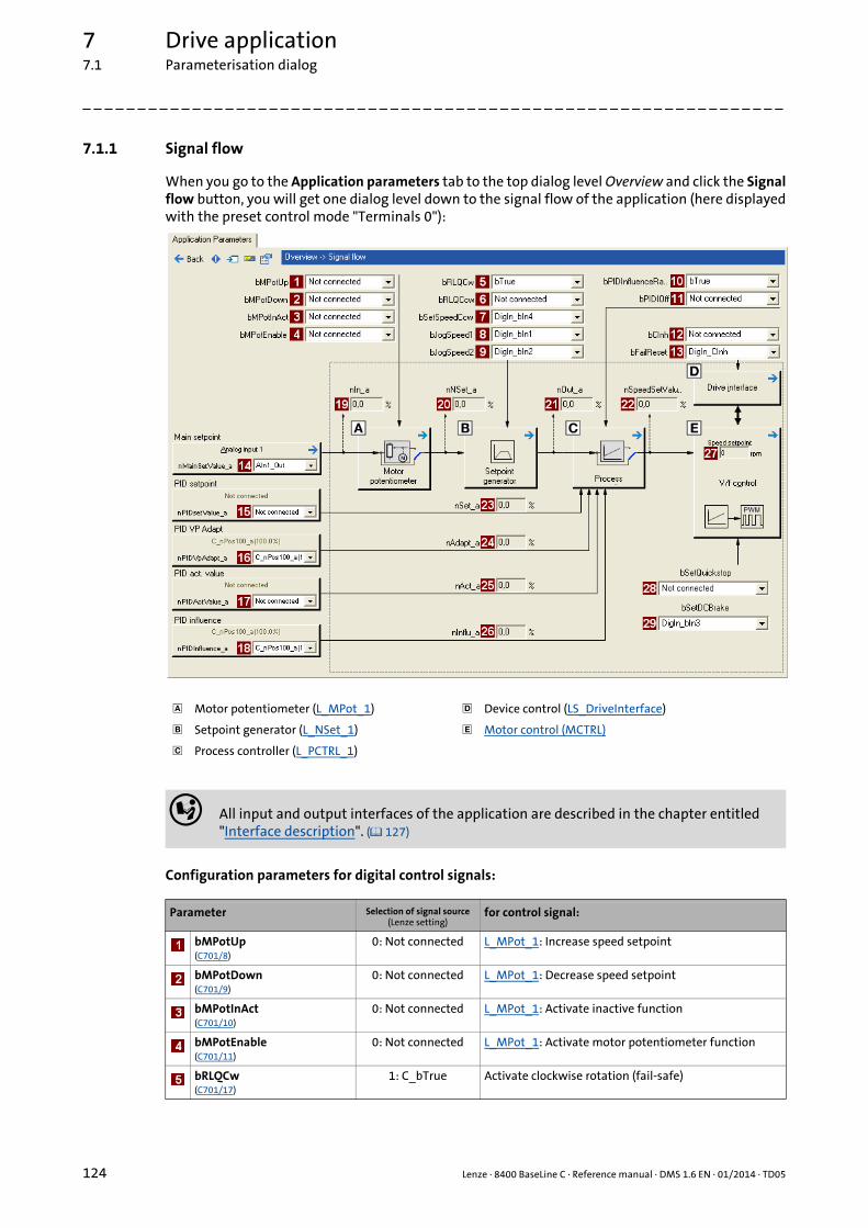
7 Drive application7.1 Parameterisation dialog
124 Lenze · 8400 BaseLine C · Reference manual · DMS 1.6 EN · 01/2014 · TD05
_ _ _ _ _ _ _ _ _ _ _ _ _ _ _ _ _ _ _ _ _ _ _ _ _ _ _ _ _ _ _ _ _ _ _ _ _ _ _ _ _ _ _ _ _ _ _ _ _ _ _ _ _ _ _ _ _ _ _ _ _ _ _ _
7.1.1 Signal flow
When you go to the Application parameters tab to the top dialog level Overview and click the Signalflow button, you will get one dialog level down to the signal flow of the application (here displayedwith the preset control mode "Terminals 0"):
Configuration parameters for digital control signals:
Motor potentiometer (L_MPot_1) Device control (LS_DriveInterface)
Setpoint generator (L_NSet_1) Motor control (MCTRL)
Process controller (L_PCTRL_1)
All input and output interfaces of the application are described in the chapter entitled "Interface description". ( 127)
Parameter Selection of signal source(Lenze setting)
for control signal:
bMPotUp(C701/8)
0: Not connected L_MPot_1: Increase speed setpoint
bMPotDown(C701/9)
0: Not connected L_MPot_1: Decrease speed setpoint
bMPotInAct(C701/10)
0: Not connected L_MPot_1: Activate inactive function
bMPotEnable(C701/11)
0: Not connected L_MPot_1: Activate motor potentiometer function
bRLQCw(C701/17)
1: C_bTrue Activate clockwise rotation (fail-safe)

Lenze · 8400 BaseLine C · Reference manual · DMS 1.6 EN · 01/2014 · TD05 125
7 Drive application7.1 Parameterisation dialog
_ _ _ _ _ _ _ _ _ _ _ _ _ _ _ _ _ _ _ _ _ _ _ _ _ _ _ _ _ _ _ _ _ _ _ _ _ _ _ _ _ _ _ _ _ _ _ _ _ _ _ _ _ _ _ _ _ _ _ _ _ _ _ _
Configuration parameters for analog setpoints:
Display parameter
bRLQCcw(C701/18)
0: Not connected Activate counter-clockwise rotation (fail-safe)
bSetSpeedCcw(C701/5)
14: DigIn_bIn4(DI4)
Change of direction of rotation
bJogSpeed1(C701/6)
11: DigIn_bIn1(DI1)
Selection of fixed setpoints (JOG setpoints)
bJogSpeed2(C701/7)
12: DigIn_bIn2(DI2)
bPIDEnableInfluenceRamp(C701/15)
1: C_bTrue L_PCTRL_1: Activate ramp for influencing factor
bPIDOff(C701/16)
0: Not connected L_PCTRL_1: Switch off I component
bCInh(C701/1)
1: C_bTrue Enable/Inhibit controller
bFailReset(C701/2)
15: DigIn_CInh(RFR)
Reset of error message
bSetQuickstop(C701/3)
0: Not connected Enable quick stop (QSP)
bSetDCBrake(C701/3)
13: DigIn_bIn3(DI3)
Manual DC-injection braking (DCB)
Parameter Selection of signal source(Lenze setting)
for setpoint selection:
nMainSetValue_a(C700/1)
10: AIn1_Out(Analog input 1)
Main setpoint• 100 % ≡ reference speed (C011)
nPIDSetValue_a(C700/9)
0: Not connected L_PCTRL_1: Sensor setpoint or process setpoint for ope-rating mode 2
nPIDVpAdapt_a(C700/6)
1: C_nPos100_a(100%)
L_PCTRL_1: Adaptation of the gain Vp set in C222 in per-cent
nPIDActValue_a(C700/7)
0: Not connected L_PCTRL_1: Actual speed value or actual sensor value (actual process value)
nPIDInfluence_a(C700/8)
1: C_nPos100_a(100%)
L_PCTRL_1: Limitation of the influencing factor in per-cent
Parameter Info
nIn_a(C830/11)
Input value of motor potentiometer
nNSet_a(C830/1)
Input value of setpoint generator
nOut_a(C830/2)
Output value of setpoint generator
nSpeedSetValue_a(C830/2)
Speed setpoint for motor control
nSet_a(C830/8)
Sensor setpoint or process setpoint for operating mode 2
nAdapt_a(C830/7)
Adaptation of the gain Vp set in C222 in percent
nAct_a(C830/6)
Speed or actual sensor value (actual process value)
Parameter Selection of signal source(Lenze setting)
for control signal:
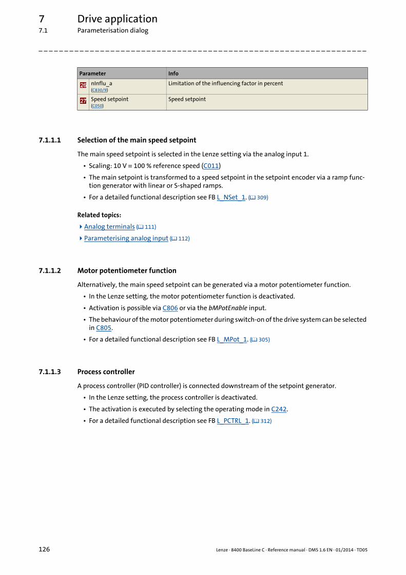
7 Drive application7.1 Parameterisation dialog
126 Lenze · 8400 BaseLine C · Reference manual · DMS 1.6 EN · 01/2014 · TD05
_ _ _ _ _ _ _ _ _ _ _ _ _ _ _ _ _ _ _ _ _ _ _ _ _ _ _ _ _ _ _ _ _ _ _ _ _ _ _ _ _ _ _ _ _ _ _ _ _ _ _ _ _ _ _ _ _ _ _ _ _ _ _ _
7.1.1.1 Selection of the main speed setpoint
The main speed setpoint is selected in the Lenze setting via the analog input 1.
• Scaling: 10 V ≡ 100 % reference speed (C011)
• The main setpoint is transformed to a speed setpoint in the setpoint encoder via a ramp func-tion generator with linear or S-shaped ramps.
• For a detailed functional description see FB L_NSet_1. ( 309)
Related topics:
Analog terminals ( 111)
Parameterising analog input ( 112)
7.1.1.2 Motor potentiometer function
Alternatively, the main speed setpoint can be generated via a motor potentiometer function.
• In the Lenze setting, the motor potentiometer function is deactivated.
• Activation is possible via C806 or via the bMPotEnable input.
• The behaviour of the motor potentiometer during switch-on of the drive system can be selected in C805.
• For a detailed functional description see FB L_MPot_1. ( 305)
7.1.1.3 Process controller
A process controller (PID controller) is connected downstream of the setpoint generator.
• In the Lenze setting, the process controller is deactivated.
• The activation is executed by selecting the operating mode in C242.
• For a detailed functional description see FB L_PCTRL_1. ( 312)
nInflu_a(C830/9)
Limitation of the influencing factor in percent
Speed setpoint(C050)
Speed setpoint
Parameter Info
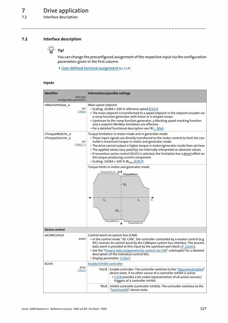
Lenze · 8400 BaseLine C · Reference manual · DMS 1.6 EN · 01/2014 · TD05 127
7 Drive application7.2 Interface description
_ _ _ _ _ _ _ _ _ _ _ _ _ _ _ _ _ _ _ _ _ _ _ _ _ _ _ _ _ _ _ _ _ _ _ _ _ _ _ _ _ _ _ _ _ _ _ _ _ _ _ _ _ _ _ _ _ _ _ _ _ _ _ _
7.2 Interface description
Tip!
You can change the preconfigured assignment of the respective input via the configurationparameters given in the first column.
User-defined terminal assignment ( 114)
Inputs
IdentifierData type
Configuration parameters
Information/possible settings
nMainSetValue_aINT
C700/1
Main speed setpoint• Scaling: 16384 ≡ 100 % reference speed (C011)• The main setpoint is transformed to a speed setpoint in the setpoint encoder via
a ramp function generator with linear or S-shaped ramps.• Upstream to the ramp function generator, a blocking speed masking function
and a setpoint MinMax limitation are effective.• For a detailed functional description see FB L_NSet.
nTorqueMotLim_anTorqueGenLim_a
INTC700/2...3
Torque limitation in motor mode and in generator mode• These input signals are directly transferred to the motor control to limit the con-
troller's maximum torque in motor and generator mode.• The drive cannot output a higher torque in motor/generator mode than set here.• The applied values (any polarity) are internally interpreted as absolute values.• If sensorless vector control (SLVC) is selected, the limitation has a direct effect on
the torque-producing current component.• Scaling: 16384 ≡ 100 % Mmax (C057)
Torque limits in motor and generator mode:
Device control
wCANControlWORD
Control word via system bus (CAN)• In the control mode "30: CAN", the controller controlled by a master control (e.g.
IPC) receives its control word by the CANopen system bus interface. The process data word is provided at this input by the upstream port block LP_CanIn1.
• See the "Process data assignment for control via CAN" subchapter for a detailed description of the individual control bits.
• Display parameter: C136/2
bCInhBOOL
C701/1
Enable/Inhibit controller
FALSE Enable controller: The controller switches to the "OperationEnabled" device state, if no other source of a controller inhibit is active.
• C158 provides a bit coded representation of all active sources/triggers of a controller inhibit.
TRUE Inhibit controller (controller inhibit): The controller switches to the "SwitchedON" device state.
nN
MN
M
-MN
-nN n
TorqueMotLimTorqueGenLim
TorqueMotLim
TorqueMotLimTorqueGenLim

7 Drive application7.2 Interface description
128 Lenze · 8400 BaseLine C · Reference manual · DMS 1.6 EN · 01/2014 · TD05
_ _ _ _ _ _ _ _ _ _ _ _ _ _ _ _ _ _ _ _ _ _ _ _ _ _ _ _ _ _ _ _ _ _ _ _ _ _ _ _ _ _ _ _ _ _ _ _ _ _ _ _ _ _ _ _ _ _ _ _ _ _ _ _
bFailResetBOOL
C701/2
Reset of error messageIn the Lenze setting this input is connected to the digital input controller enable so that a possibly existing error message is reset together with the controller enable (if the cause for the fault is eliminated).
TRUE The current fault is reset, if the cause for the fault is eliminated.• If the fault still exists, the error status remains unchanged.
bSetQuickstopBOOL
C701/3
Enable quick stop (QSP)• Also see device command "Activate/Deactivate quick stop".
TRUE Activate quick stop• The motor control is decoupled from the setpoint selection and
within the deceleration time parameterised in C105 the motor is brought to a standstill (nist = 0).
• The motor is kept at a standstill during closed-loop operation.• A pulse inhibit (CINH) is set if the "Auto-DCB" function has been
activated via C019.
FALSE Deactivate quick stop• The quick stop is deactivated if no other source for the quick stop
is active.• C159 provides a bit coded representation of all active sources/
triggers of a quick stop.
bSetDCBrakeBOOL
C701/4
Manual DC-injection braking (DCB)• Detailed information on DC-injection braking is provided in the motor control,
subchapter "DC-injection braking".
Note!
Holding braking is not possible when this braking mode is used!
FALSE Deactivate DC-injection braking.
TRUE Activate DC-injection braking, i.e. the drive is brought to a standstill by means of DC-injection braking.
• The braking effect stops when the rotor is at standstill.• After the hold time ((C107) has expired, the controller sets the
pulse inhibit (CINH).
Fail-safe selection of the direction of rotation in connection with quick stop• In control mode "Terminals 16", both inputs are connected to the digital terminals DI3 and DI4.• For a detailed functional description see FB L_RLQ.
bRLQCwBOOL
C701/17
Activate clockwise rotation (fail-safe)
FALSE Quick stop
TRUE Clockwise rotation
bRLQCcwBOOL
C701/18
Activate counter-clockwise rotation (fail-safe)
FALSE Quick stop
TRUE Counter-clockwise rotation
IdentifierData type
Configuration parameters
Information/possible settings
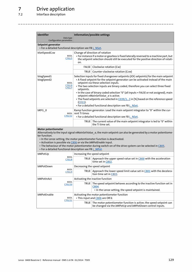
Lenze · 8400 BaseLine C · Reference manual · DMS 1.6 EN · 01/2014 · TD05 129
7 Drive application7.2 Interface description
_ _ _ _ _ _ _ _ _ _ _ _ _ _ _ _ _ _ _ _ _ _ _ _ _ _ _ _ _ _ _ _ _ _ _ _ _ _ _ _ _ _ _ _ _ _ _ _ _ _ _ _ _ _ _ _ _ _ _ _ _ _ _ _
Setpoint generator• For a detailed functional description see FB L_NSet.
bSetSpeedCcwBOOL
C701/5
Change of direction of rotation• For instance if a motor or gearbox is fixed laterally reversed to a machine part, but
the setpoint selection should still be executed for the positive direction of rotati-on.
FALSE Clockwise rotation (Cw)
TRUE Counter-clockwise rotation (Ccw)
bJogSpeed1bJogSpeed2
BOOLC701/6C701/7
Selection inputs for fixed changeover setpoints (JOG setpoints) for the main setpoint• A fixed setpoint for the setpoint generator can be activated instead of the main
setpoint via these selection inputs.• The two selection inputs are binary coded, therefore you can select three fixed
setpoints.• In the case of binary coded selection "0" (all inputs = FALSE or not assigned), main
setpoint nMainSetValue_a is active.• The fixed setpoints are selected in C039/1...3 in [%] based on the reference speed
(C011).• For a detailed functional description see FB L_NSet.
bRFG_0BOOL
C701/12
Ramp function generator: Lead the main setpoint integrator to "0" within the cur-rent Ti times
• For a detailed functional description see FB L_NSet.
TRUE The current value of the main setpoint integrator is led to "0" within the Ti time set.
Motor potentiometerAlternatively to the input signal nMainSetValue_a, the main setpoint can also be generated by a motor potentiome-ter function.
• In the Lenze setting, the motor potentiometer function is deactivated.• Activation is possible via C806 or via the bMPotEnable input.• The behaviour of the motor potentiometer during switch-on of the drive system can be selected in C805.• For a detailed functional description see FB L_MPot.
bMPotUpBOOL
C701/8
Increasing the speed setpoint
TRUE Approach the upper speed value set in C800 with the acceleration time set in C802.
bMPotDownBOOL
C701/9
Decreasing the speed setpoint
TRUE Approach the lower speed limit value set in C801 with the decelera-tion time set in C803.
bMPotInActBOOL
C701/10
Activating the inactive function
TRUE The speed setpoint behaves according to the inactive function set in C804.
• In the Lenze setting, the speed setpoint is maintained.
bMPotEnableBOOL
C701/11
Activating the motor potentiometer function• This input and C806 are OR'd.
TRUE The motor potentiometer function is active; the speed setpoint can be changed via the bMPotUp and bMPotDown control inputs.
IdentifierData type
Configuration parameters
Information/possible settings

7 Drive application7.2 Interface description
130 Lenze · 8400 BaseLine C · Reference manual · DMS 1.6 EN · 01/2014 · TD05
_ _ _ _ _ _ _ _ _ _ _ _ _ _ _ _ _ _ _ _ _ _ _ _ _ _ _ _ _ _ _ _ _ _ _ _ _ _ _ _ _ _ _ _ _ _ _ _ _ _ _ _ _ _ _ _ _ _ _ _ _ _ _ _
Outputs
Process controller• In the Lenze setting, the process controller is deactivated.• The activation is executed by selecting the operating mode in C242.• For a detailed functional description see FB L_PCTRL.
bPIDEnableInfluenceRampBOOL
C701/15
Activate ramp for influencing factor
FALSE Influencing factor of the PID controller is ramped down to "0".
TRUE Influencing factor of the PID controller is ramped up to the value nPIDInfluence_a.
bPIDOffBOOL
C701/16
Switch off I-component of the process controller• In conjunction with the operating mode set in C242
(Lenze setting: "Off).
TRUE I-component of the process controller is switched off.
nPIDVpAdapt_aINT
C700/6
Adaptation of the gain Vp set in C222 in percent• Scaling: 16384 ≡ 100 %• Internal limitation to ±199.9 %• Changes can be done online.
nPIDActValue_aINT
C700/7
Speed or actual sensor value (actual process value)• Scaling: 16384 ≡ 100 %• Internal limitation to ±199.9 %
nPIDInfluence_aINT
C700/8
Limitation of the influencing factor in percent• The influence factor of the PID controller can be limited to a certain value (-
199.9% ... +199.9%) via nPIDInfluence_a.• Scaling: 16384 ≡ 100 %• Internal limitation to ±199.9 %
nPIDSetValue_aINT
C700/9
Sensor setpoint or process setpoint for operating mode 2• Scaling: 16384 ≡ 100 %• Internal limitation to ±199.9 %
IdentifierData type
Value/meaning
Device control
wDeviceStateWordWORD
Status word of the controller (based on DSP-402)• The status word contains information on the currents status of the drive control-
ler.• In control mode "30: CAN", the status word is transmitted to the master control
as process data word via the LP_CanOut1 port block.• For a detailed description of the individual status bits, see subchapter entitled
"Process data assignment for control via CAN.• Display parameter: C150
wDeviceAuxStateWordWORD
Extended status word of the controller
wDetermFailNoLowWORD
Display of the current error (Low-Word)
wDetermFailNoHighWORD
Display of the current error (High-Word)
bDriveFailBOOL
TRUE Controller in error status• "Fault" device state is active.
bDriveReadyBOOL
TRUE Controller is ready for operation.• "SwitchedON" device state is active.• The drive is in this device state if the DC bus voltage is applied and
the controller is still inhibited by the user (controller inhibit).
IdentifierData type
Configuration parameters
Information/possible settings

Lenze · 8400 BaseLine C · Reference manual · DMS 1.6 EN · 01/2014 · TD05 131
7 Drive application7.2 Interface description
_ _ _ _ _ _ _ _ _ _ _ _ _ _ _ _ _ _ _ _ _ _ _ _ _ _ _ _ _ _ _ _ _ _ _ _ _ _ _ _ _ _ _ _ _ _ _ _ _ _ _ _ _ _ _ _ _ _ _ _ _ _ _ _
bCInhActiveBOOL
TRUE Controller inhibit is active
bQSPIsActiveBOOL
TRUE Quick stop is active
bSafeTorqueOffBOOL
TRUE "SafeTorqueOff" device state is active
bSafetyIsActiveBOOL
TRUE In preparation
bSpeedCcwBOOL
FALSE Clockwise rotation (Cw)
TRUE Counter-clockwise rotation (Ccw)
bActSpeedEqZeroBOOL
TRUE Current speed is 0
bSpeedSetReachedBOOL
TRUE Speed setpoint reached
bSpeedActEqSetBOOL
TRUE Actual speed value has reached the setpoint within one hysteresis band
bNactCompareBOOL
TRUE During open-loop operation:Speed setpoint < comparison value (C024)
During closed-loop operation:Actual speed value < comparison value (C024)
bImaxActiveBOOL
TRUE The current setpoint is limited internally(the controller operates at the maximum current limit)
Motor control
bHeatSinkWarningBOOL
TRUE Heatsink overtemperature detected
bOVDetectedBOOL
TRUE Overvoltage detected
bDcBrakeOnBOOL
TRUE DC-injection braking active
bFlyingSyncActiveBOOL
TRUE Flying restart function is executed
nMotorFreqAct_aC058 | INT
Current field frequency
nOutputSpeedCtrl_aINT
Speed or slip controller output• Scaling: 16384 ≡ 100 % reference speed (C011)
nMotorSpeedAct_aC051 | INT
Actual speed value• Scaling: 16384 ≡ 100 % reference speed (C011)
nMotorVoltage_aINT
Current motor voltage/inverter output voltage• Scaling: 16384 ≡ 1000 V
nDCVoltage_aINT
Actual DC-bus voltage• Scaling: 16384 ≡ 1000 V
nMotorCurrent_aINT
Current motor current• Scaling: 16384 ≡ 100 % Imax_mot (C022)
nMotorTorqueAct_aC056/2 | INT
Actual torque• With "VFC (+encoder)" motor control, this value is determined from the current
motor current and corresponds to the actual torque only by approximation.• Scaling: 16384 ≡ 100 % Mmax (C057)
nHeatsinktemperature_aINT
Heatsink temperature
IdentifierData type
Value/meaning

7 Drive application7.3 Setting parameters (short overview)
132 Lenze · 8400 BaseLine C · Reference manual · DMS 1.6 EN · 01/2014 · TD05
_ _ _ _ _ _ _ _ _ _ _ _ _ _ _ _ _ _ _ _ _ _ _ _ _ _ _ _ _ _ _ _ _ _ _ _ _ _ _ _ _ _ _ _ _ _ _ _ _ _ _ _ _ _ _ _ _ _ _ _ _ _ _ _
7.3 Setting parameters (short overview)
Parameter Info Lenze setting
Value Unit
C012 Accel. time - main setpoint 2.0 s
C013 Decel. time - main setpoint 2.0 s
C182 S-ramp time PT1 20.00 s
C134 Ramp smoothing - main setpoint 0: Off
C019 Auto-DCB: Threshold 3 rpm
C036 DCB: Current 50.0 %
C039/1 Fixed setpoint 1 40.0 %
C039/2 Fixed setpoint 2 60.0 %
C039/3 Fixed setpoint 3 80.0 %
C105 Deceleration time - quick stop 5.0 s
C106 Auto-DCB: Hold time 0.5 s
C107 DCB: Hold time 999.0 s
C222 L_PCTRL_1: Vp 1.0
C223 L_PCTRL_1: Tn 400 ms
C224 L_PCTRL_1: Kd 0.0
C225 L_PCTRL_1: MaxLimit 199.9 %
C226 L_PCTRL_1: MinLimit -199.9 %
C227 L_PCTRL_1: Acceleration time 0.1 s
C228 L_PCTRL_1: Deceleration time 0.1 s
C231/1 L_PCTRL_1: Pos. maximum 199.9 %
C231/2 L_PCTRL_1: Pos. minimum 0.0 %
C231/3 L_PCTRL_1: Neg. minimum 0.0 %
C231/4 L_PCTRL_1: Neg. maximum 199.9 %
C242 L_PCTRL_1: Operating mode 0: Off
C243 L_PCTRL_1: Acceleration time influence 5.0 s
C244 L_PCTRL_1: Deceleration time influence 5.0 s
C245 L_PCTRL_1: PID output value - %
C800 L_MPot_1: Upper limit 100.0 %
C801 L_MPot_1: Lower limit -100.0 %
C802 L_MPot_1: Acceleration time 10.0 s
C803 L_MPot_1: Deceleration time 10.0 s
C804 L_MPot_1: Inactive function 0: Retain value
C805 L_MPot_1: Init function 0: Load last value
C806 L_MPot_1: Use 0: No
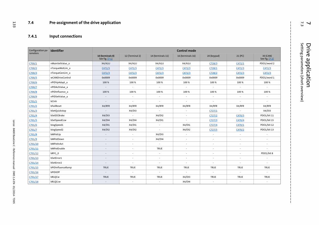
7D
rive application7.3
Setting param
eters (short overview
)
133Len
ze · 8400 BaseLin
e C · Referen
ce man
ual · D
MS 1.6 EN
· 01/2014 · TD05
_ _ _ _ _ _ _ _ _ _ _ _ _ _ _ _ _ _ _ _ _ _ _ _ _ _ _ _ _ _ _ _ _ _ _ _ _ _ _ _ _ _ _ _ _ _ _ _ _ _ _ _ _ _ _ _ _ _ _ _ _ _ _ _
7.4 Pre-assignment of the drive application
7.4.1 Input connections
Configuration pa-rameters
Identifier Control mode
10 (terminals 0)See fig. [7-1]
12 (Terminal 2) 14 (terminals 11) 16 (terminals 16) 20 (keypad) 21 (PC) 30 (CAN)See fig. [7-2]
C700/1 nMainSetValue_a X4/A1U X4/A1U X4/A1U X4/A1U C728/3 C472/1 PDO1/word 2
C700/2 nTorqueMotLim_a C472/3 C472/3 C472/3 C472/3 C728/1 C472/3 C472/3
C700/3 nTorqueGenLim_a C472/3 C472/3 C472/3 C472/3 C728/2 C472/3 C472/3
C700/5 wCANDriveControl 0x0009 0x0009 0x0009 0x0009 0x0009 0x0009 PDO1/word 1
C700/6 nPIDVpAdapt_a 100 % 100 % 100 % 100 % 100 % 100 % 100 %
C700/7 nPIDActValue_a - - - - - - -
C700/8 nPIDInfluence_a 100 % 100 % 100 % 100 % 100 % 100 % 100 %
C700/9 nPIDSetValue_a - - - - - - -
C701/1 bCInh - - - - - - -
C701/2 bFailReset X4/RFR X4/RFR X4/RFR X4/RFR X4/RFR X4/RFR X4/RFR
C701/3 bSetQuickstop - X4/DI3 - - C727/1 - X4/DI3
C701/4 bSetDCBrake X4/DI3 - X4/DI2 - C727/2 C470/3 PDO1/bit 11
C701/5 bSetSpeedCcw X4/DI4 X4/DI4 X4/DI1 - C727/3 C470/4 PDO1/bit 15
C701/6 bJogSpeed1 X4/DI1 X4/DI1 - X4/DI1 C727/4 C470/1 PDO1/bit 12
C701/7 bJogSpeed2 X4/DI2 X4/DI2 - X4/DI2 C727/5 C470/2 PDO1/bit 13
C701/8 bMPotUp - - X4/DI3 - - - -
C701/9 bMPotDown - - X4/DI4 - - - -
C701/10 bMPotInAct - - - - - - -
C701/11 bMPotEnable - - TRUE - - - -
C701/12 bRFG_0 - - - - - - PDO1/bit 8
C701/13 bSetError1 - - - - - - -
C701/14 bSetError2 - - - - - - -
C701/15 bPIDInfluenceRamp TRUE TRUE TRUE TRUE TRUE TRUE TRUE
C701/16 bPIDIOff - - - - - - -
C701/17 bRLQCw TRUE TRUE TRUE X4/DI3 TRUE TRUE TRUE
C701/18 bRLQCcw - - - X4/DI4 - - -

7D
rive application7.3
Setting param
eters (short overview
)
Lenze · 8400 B
aseLine C
· Reference m
anu
al · DM
S 1.6 EN · 01/2014 · TD
05134
_ _ _ _ _ _ _ _ _ _ _ _ _ _ _ _ _ _ _ _ _ _ _ _ _ _ _ _ _ _ _ _ _ _ _ _ _ _ _ _ _ _ _ _ _ _ _ _ _ _ _ _ _ _ _ _ _ _ _ _ _ _ _ _ 7.4.2 Output connections
Configuration pa-rameters
Identifier Control mode
10 (terminals 0)See fig. [7-1]
12 (Terminal 2) 14 (terminals 11) 16 (terminals 16) 20 (keypad) 21 (PC) 30 (CAN)See fig. [7-2]
C620/5 LS_DisFree: wDis1 (C481/1) - - - - wDeviceStateWord -
C620/6 LS_DisFree: wDis2 (C481/2) - - - - - - -
C620/7 LS_DisFree: wDis3 (C481/3) - - - - - - -
C620/8 LS_DisFree: wDis4 (C481/4) - - - - - - -
C620/9 LS_DisFree_a: nDis1_a (C482/1) - - - - nMotorSpeedAct_a -
C620/10 LS_DisFree_a: nDis2_a (C482/2) - - - - nOutputSpeedCtrl_a -
C620/11 LS_DisFree_a: nDis3_a (C482/3) - - - - - - -
C620/12 LS_DisFree_a: nDis4_a (C482/4) - - - - - - -
C620/20 LP_CanOut1: wState - - - - - - wDeviceStateWord
C620/21 LP_CanOut1: wOut2 - - - - - - nMotorSpeedAct_a
C620/22 LP_CanOut1: wOut3 - - - - - - nOutputSpeedCtrl_a
C620/23 LP_CanOut1: wOut4 - - - - - - -
C620/24 LP_CanOut2: wOut1 - - - - - - -
C620/25 LP_CanOut2: wOut2 - - - - - - -
C620/26 LP_CanOut2: wOut3 - - - - - - -
C620/27 LP_CanOut2: wOut4 - - - - - - -
C621/1 LS_DigitalOutput:bRelay (X101) bDriveFail bDriveFail
C621/2 LS_DigitalOutput:bOut1 (X4/DO1) bDriveReady bDriveReady
C621/6 USER-LED bNactCompare bNactCompare
C621/7 LA_NCtrl: bStatusBit0 - - - - - - -
C621/8 LA_NCtrl: bStatusBit2 bImaxActive bImaxActive
C621/9 LA_NCtrl: bStatusBit3 bSpeedSetReached bSpeedSetReached
C621/10 LA_NCtrl: bStatusBit4 bSpeedActEqSet bSpeedActEqSet
C621/11 LA_NCtrl: bStatusBit5 bNactCompare bNactCompare
C621/12 LA_NCtrl: bStatusBit14 bSpeedCcw bSpeedCcw
C621/13 LA_NCtrl: bStatusBit15 bDriveReady bDriveReady
C621/16 LS_DisFree_b: bDis1 (C480/Bit0) - - - - bDriveReady -
C621/17 LS_DisFree_b: bDis2 (C480/Bit1) - - - - bDriveFail -
C621/18...C621/23
LS_DisFree_b: bDis3 (C480/Bit2)...LS_DisFree_b: bDis8 (C480/Bit7)
- - - - - - -
C621/30...45 LP_CanOut1: bState_B0 ... B15 - - - - - - -
C621/46...61 LP_CanOut2: bOut1_B0 ... B15 - - - - - - -
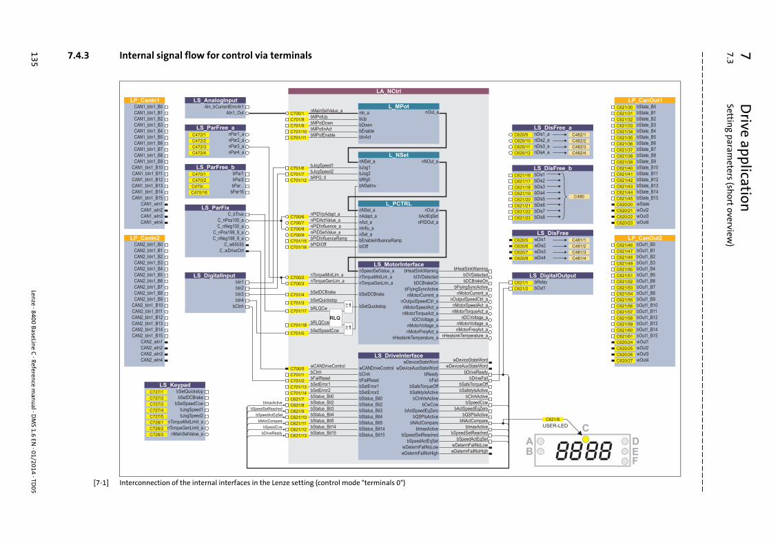
7D
rive application7.3
Setting param
eters (short overview
)
135Len
ze · 8400 BaseLin
e C · Referen
ce man
ual · D
MS 1.6 EN
· 01/2014 · TD05
_ _ _ _ _ _ _ _ _ _ _ _ _ _ _ _ _ _ _ _ _ _ _ _ _ _ _ _ _ _ _ _ _ _ _ _ _ _ _ _ _ _ _ _ _ _ _ _ _ _ _ _ _ _ _ _ _ _ _ _ _ _ _ _
7.4.3 Internal signal flow for control via terminals
[7-1] Interconnection of the internal interfaces in the Lenze setting (control mode "terminals 0")
AIn_bCurrentErrorIn1
AIn1_Out
bPar1
bPar2
bPar...
bPar16
C_bTrue
C_nPos100_a
C_nNeg100_a
C_nPos199_9_a
C_nNeg199_9_a
C_w65535
C_wDriveCtrl
nPar1_a
nPar2_a
nPar3_a
nPar4_a
bCInh
bIn1
bIn2
bIn3
bIn4
bDriveReady
bSpeedCcw
bSpeedSetReached
bNActCompare
bImaxActive
bSpeedActEqSet
LS_ParFix
LS_ParFree_a
LS_DigitalInput
LS_ParFree_b
LS_AnalogInput
bSetQuickstop
bSetDCBrake
nTorqueMotLimit_a
nTorqueGenLimit_a
bSetSpeedCcw
nMainSetValue_a
bJogSpeed1
bJogSpeed2
LS_KeypadC727/1
C727/2
C728/1
C728/2
C727/3
C728/3
C727/4
C727/5
C /2470
C /...470
C /16470
C470/1
C /2472
C /3472
C /4472
C472/1
nOut_a
bUp
bDown
bInAct
nln_a
bEnable
bRfg0
nAdapt_anPIDVpAdapt_anNSet_a
bNSetInv
bEnableInfluenceRampbPIDInfluenceRamp
bIOffbPIDIOff
bSetDCBrake
bSetQuickstop
nNSet_a
nSet_anPIDSetValue_a
nTorqueMotLim_a
bSetDCBrake
bRLQCw
bRLQCcw
bFailReset
bSetQuickstop
bCInh
bRFG_0
nTorqueGenLim_a
bJog2
nInflu_anPIDInfluence_a
bJogSpeed2bJog1
nAct_anPIDActValue_a
bJogSpeed1
bCInhActive
bDriveReady
wDeviceStateWord
wDeviceAuxStateWord
wDetermFailNoLow
wDetermFailNoHigh
nNOut_a
nOut_a
bActEqSet
nPIDOut_a
bFailReset
bSetError2bSetError2
bCInh
bMPotDown
bMPotUp
bMPotEnable
bMPotInAct
nMainSetValue_a
bSetSpeedCcw
bSetError1bSetError1
bStatus_Bit0bStatus_Bit0
bStatus_Bit2bStatus_Bit2
bStatus_Bit3bStatus_Bit3
bStatus_Bit4bStatus_Bit4
bStatus_Bit5bStatus_Bit5
bStatus_Bit14bStatus_Bit14
bStatus_Bit15bStatus_Bit15
wDetermFailNoLow
wDetermFailNoHigh
bReady
wDeviceStateWord
wDeviceAuxStateWord
bFail
bSafeTorqueOff bSafeTorqueOff
bSafetyIsActive bSafetyIsActive
bCInhIsActive
bSpeedActEqSet
nTorqueMotLim_a
nTorqueGenLim_a
bQSPIsActive
bNActCompare
bCwCcw
bImaxActive
bActSpeedEqZero
bSpeedActEqSet
bDriveFail
bHeatSinkWarningbHeatSinkWarningbOVDetectedbOVDetectedbDCBrakeOnbDCBrakeOn
nMotorCurrent_anMotorCurrent_anOutputSpeedCtrl_anOutputSpeedCtrl_anMotorSpeedAct_anMotorSpeedAct_anMotorTorqueAct_anMotorTorqueAct_a
nDCVoltage_anDCVoltage_a
nHeatsinkTemperature_a
bFlyingSyncActive
nHeatsinkTemperature_a
bFlyingSyncActive
nMotorVoltage_a nMotorVoltage_a
nMotorFreqAct_a nMotorFreqAct_a
bSpeedCcw
bActSpeedEqZero
bQSPIsActive
bNActCompare
bSpeedSetReachedbSpeedSetReached
bImaxActive
1
nSpeedSetValue_a
1
RLQ
LA_NCtrl
L_MPot
L_NSet
L_PCTRL
LS_MotorInterface
LS_DriveInterface
LS_DisFree_bbDis1
bDis2
bDis3
bDis4
bDis5
bDis6
bDis7
bDis8
LS_DisFree_anDis1_a
nDis2_a
nDis3_a
nDis4_a
LS_DisFreewDis1
wDis2
wDis3
wDis4
B
C
DEF
A
8888
USER-LED
LS_DigitalOutputbRelay
bOut1
C /2482
C /3482
C /4482
C482/1
C480
C /2481
C /3481
C /4481
C481/1
C700/1
C701/8
C701/9
C701/10
C701/11
C701/6
C701/7
C701/12
C700/6
C700/7
C700/8
C700/9
C701/15
C701/16
C700/2
C700/3
C701/4
C701/3
C701/17
C701/18
C701/5
C701/1
C701/2
C701/13
C701/14
C621/7
C621/8
C621/9
C621/10
C621/11
C621/12
C621/13
C620/9
C /10620
C /11620
C /12620
C621/16
C621/17
C /18621
C /19621
C /20621
C /21621
C /22621
C /23621
C620/5
C /6620
C /7620
C /8620
C /1621
C /2621
C /6621
CAN1_bIn1_B0
CAN1_bIn1_B1
CAN1_bIn1_B2
CAN1_bIn1_B3
CAN1_bIn1_B4
CAN1_bIn1_B5
CAN1_bIn1_B6
CAN1_bIn1_B7
CAN1_bIn1_B8
CAN1_bIn1_B9
CAN1_bIn1_B10
CAN1_bIn1_B11
CAN1_bIn1_B12
CAN1_bIn1_B13
CAN1_bIn1_B14
CAN1_bIn1_B15
CAN1_wIn1
CAN1_wIn2
CAN1_wIn3
CAN1_wIn4
LP_CanIn1
CAN2_bIn1_B0
CAN2_bIn1_B1
CAN2_bIn1_B2
CAN2_bIn1_B3
CAN2_bIn1_B4
CAN2_bIn1_B5
CAN2_bIn1_B6
CAN2_bIn1_B7
CAN2_bIn1_B8
CAN2_bIn1_B9
CAN2_bIn1_B10
CAN2_bIn1_B11
CAN2_bIn1_B12
CAN2_bIn1_B13
CAN2_bIn1_B14
CAN2_bIn1_B15
CAN2_wIn1
CAN2_wIn2
CAN2_wIn3
CAN2_wIn4
LP_CanIn2
bState_B0
b _B1State
b _B2State
b _B3State
b _B4State
b _B5State
b _B6State
b _B7State
b _B8State
b _B9State
b _B10State
b _B11State
b _B12State
b _B13State
b _B14State
b _B15State
wState
w 2Out
w 3Out
w 4Out
LP_CanOut1
bOut1_B0
b _B1Out1
b _B2Out1
b _B3Out1
b _B4Out1
b _B5Out1
b _B6Out1
b _B7Out1
b _B8Out1
b _B9Out1
b _B10Out1
b _B11Out1
b _B12Out1
b _B13Out1
b _B14Out1
b _B15Out1
wOut1
w 2Out
w 3Out
w 4Out
LP_CanOut2
C /30621
C /31621
C /32621
C /33621
C /34621
C /35621
C /36621
C /37621
C /38621
C /39621
C /40621
C /41621
C /42621
C /43621
C /44621
C /45621
C /20620
C /21620
C /22620
C /23620
C /46621
C /47621
C /48621
C /49621
C /50621
C /51621
C /52621
C /53621
C /54621
C /55621
C /56621
C /57621
C /58621
C /59621
C /60621
C /61621
C /24620
C /25620
C /26620
C /27620
wCANDriveControlwCANDriveControlC700/5

7D
rive application7.3
Setting param
eters (short overview
)
Lenze · 8400 B
aseLine C
· Reference m
anu
al · DM
S 1.6 EN · 01/2014 · TD
05136
_ _ _ _ _ _ _ _ _ _ _ _ _ _ _ _ _ _ _ _ _ _ _ _ _ _ _ _ _ _ _ _ _ _ _ _ _ _ _ _ _ _ _ _ _ _ _ _ _ _ _ _ _ _ _ _ _ _ _ _ _ _ _ _ 7.4.4 Internal signal flow for control via CAN
[7-2] Interconnection of the internal interfaces for control via system bus (control mode "CAN")
AIn_bCurrentErrorIn1
AIn1_Out
bDriveReady
bSpeedCcw
bSpeedSetReached
bNActCompare
bImaxActive
bSpeedActEqSet
C_bTrue
C_nPos100_a
C_nNeg100_a
C_nPos199_9_a
C_nNeg199_9_a
C_w65535
C_wDriveCtrl
LS_ParFix
bCInh
bIn1
bIn2
bIn3
bIn4
LS_DigitalInput
LS_AnalogInput
bSetQuickstop
bSetDCBrake
nTorqueMotLimit_a
nTorqueGenLimit_a
bSetSpeedCcw
nMainSetValue_a
bJogSpeed1
bJogSpeed2
LS_KeypadC727/1
C727/2
C728/1
C728/2
C727/3
C728/3
C727/4
C727/5
bPar1
bPar2
bPar...
bPar16
LS_ParFree_b
C /2470
C /...470
C /16470
C470/1
nPar1_a
nPar2_a
nPar3_a
nPar4_a
LS_ParFree_a
C /2472
C /3472
C /4472
C472/1
nOut_a
bUp
bDown
bInAct
nln_a
bEnable
bRfg0
nAdapt_anPIDVpAdapt_anNSet_a
bNSetInv
bEnableInfluenceRampbPIDInfluenceRamp
bIOffbPIDIOff
bSetDCBrake
bSetQuickstop
nNSet_a
nSet_anPIDSetValue_a
nTorqueMotLim_a
bSetDCBrake
bRLQCw
bRLQCcw
bFailReset
bSetQuickstop
bCInh
bRFG_0
nTorqueGenLim_a
bJog2
nInflu_anPIDInfluence_a
bJogSpeed2bJog1
nAct_anPIDActValue_a
bJogSpeed1
bCInhActive
bDriveReady
wDeviceStateWord
wDeviceAuxStateWord
wDetermFailNoLow
wDetermFailNoHigh
nNOut_a
nOut_a
bActEqSet
nPIDOut_a
bFailReset
bSetError2bSetError2
bCInh
bMPotDown
bMPotUp
bMPotEnable
bMPotInAct
nMainSetValue_a
bSetSpeedCcw
bSetError1bSetError1
bStatus_Bit0bStatus_Bit0
bStatus_Bit2bStatus_Bit2
bStatus_Bit3bStatus_Bit3
bStatus_Bit4bStatus_Bit4
bStatus_Bit5bStatus_Bit5
bStatus_Bit14bStatus_Bit14
bStatus_Bit15bStatus_Bit15
wDetermFailNoLow
wDetermFailNoHigh
bReady
wDeviceStateWord
wDeviceAuxStateWord
bFail
bSafeTorqueOff bSafeTorqueOff
bSafetyIsActive bSafetyIsActive
bCInhIsActive
bSpeedActEqSet
nTorqueMotLim_a
nTorqueGenLim_a
bQSPIsActive
bNActCompare
bCwCcw
bImaxActive
bActSpeedEqZero
bSpeedActEqSet
bDriveFail
bHeatSinkWarningbHeatSinkWarningbOVDetectedbOVDetectedbDCBrakeOnbDCBrakeOn
nMotorCurrent_anMotorCurrent_anOutputSpeedCtrl_anOutputSpeedCtrl_anMotorSpeedAct_anMotorSpeedAct_anMotorTorqueAct_anMotorTorqueAct_a
nDCVoltage_anDCVoltage_a
nHeatsinkTemperature_a
bFlyingSyncActive
nHeatsinkTemperature_a
bFlyingSyncActive
nMotorVoltage_a nMotorVoltage_a
nMotorFreqAct_a nMotorFreqAct_a
bSpeedCcw
bActSpeedEqZero
bQSPIsActive
bNActCompare
bSpeedSetReachedbSpeedSetReached
bImaxActive
1
nSpeedSetValue_a
1
RLQ
LA_NCtrl
L_MPot
L_NSet
L_PCTRL
LS_MotorInterface
LS_DriveInterface
LS_DisFreewDis1
wDis2
wDis3
wDis4
B
C
DEF
A
8888
USER-LED
C /2481
C /3481
C /4481
C481/1
C700/1
C701/8
C701/9
C701/10
C701/11
C701/6
C701/7
C701/12
C700/6
C700/7
C700/8
C700/9
C701/15
C701/16
C700/2
C700/3
C701/4
C701/3
C701/17
C701/18
C701/5
C701/1
C701/2
C701/13
C701/14
C621/7
C621/8
C621/9
C621/10
C621/11
C621/12
C621/13
C620/5
C /6620
C /7620
C /8620
LS_DigitalOutputbRelay
bOut1C /1621
C /2621
C /6621
LS_DisFree_anDis1_a
nDis2_a
nDis3_a
nDis4_a
C /2482
C /3482
C /4482
C482/1C620/9
C /10620
C /11620
C /12620
LS_DisFree_bbDis1
bDis2
bDis3
bDis4
bDis5
bDis6
bDis7
bDis8
C480
C621/16
C621/17
C /18621
C /19621
C /20621
C /21621
C /22621
C /23621
CAN2_bIn1_B0
CAN2_bIn1_B1
CAN2_bIn1_B2
CAN2_bIn1_B3
CAN2_bIn1_B4
CAN2_bIn1_B5
CAN2_bIn1_B6
CAN2_bIn1_B7
CAN2_bIn1_B8
CAN2_bIn1_B9
CAN2_bIn1_B10
CAN2_bIn1_B11
CAN2_bIn1_B12
CAN2_bIn1_B13
CAN2_bIn1_B14
CAN2_bIn1_B15
CAN2_wIn1
CAN2_wIn2
CAN2_wIn3
CAN2_wIn4
LP_CanIn2
wCANDriveControlwCANDriveControlC700/5
SetDCBrake
JogSpeed1
JogSpeed2
SetSpeedCcw
CAN1_bIn1_B0
CAN1_bIn1_B1
CAN1_bIn1_B2
CAN1_bIn1_B3
CAN1_bIn1_B4
CAN1_bIn1_B5
CAN1_bIn1_B6
CAN1_bIn1_B7
CAN1_bIn1_B8
CAN1_bIn1_B9
CAN1_bIn1_B10
CAN1_bIn1_B11
CAN1_bIn1_B12
CAN1_bIn1_B13
CAN1_bIn1_B14
CAN1_bIn1_B15
CAN1_wIn1
CAN1_wIn2
CAN1_wIn3
CAN1_wIn4
LP_CanIn1bState_B0
b _B1State
b _B2State
b _B3State
b _B4State
b _B5State
b _B6State
b _B7State
b _B8State
b _B9State
b _B10State
b _B11State
b _B12State
b _B13State
b _B14State
b _B15State
wState
w 2Out
w 3Out
w 4Out
LP_CanOut1C /30621
C /31621
C /32621
C /33621
C /34621
C /35621
C /36621
C /37621
C /38621
C /39621
C /40621
C /41621
C /42621
C /43621
C /44621
C /45621
C /20620
C /21620
C /22620
C /23620
bOut1_B0
b _B1Out1
b _B2Out1
b _B3Out1
b _B4Out1
b _B5Out1
b _B6Out1
b _B7Out1
b _B8Out1
b _B9Out1
b _B10Out1
b _B11Out1
b _B12Out1
b _B13Out1
b _B14Out1
b _B15Out1
wOut1
w 2Out
w 3Out
w 4Out
LP_CanOut2C /46621
C /47621
C /48621
C /49621
C /50621
C /51621
C /52621
C /53621
C /54621
C /55621
C /56621
C /57621
C /58621
C /59621
C /60621
C /61621
C /24620
C /25620
C /26620
C /27620
SetHalt
CANDriveControl
MainSetValue
DeviceStateWord
MotorSpeedAct
OutputSpeedCtrl

Lenze · 8400 BaseLine C · Reference manual · DMS 1.6 EN · 01/2014 · TD05 137
7 Drive application7.3 Setting parameters (short overview)
_ _ _ _ _ _ _ _ _ _ _ _ _ _ _ _ _ _ _ _ _ _ _ _ _ _ _ _ _ _ _ _ _ _ _ _ _ _ _ _ _ _ _ _ _ _ _ _ _ _ _ _ _ _ _ _ _ _ _ _ _ _ _ _
7.4.5 Process data assignment for control via CAN
The CAN communication (preconfiguration) is connected to the technology application by selectingthe control mode "30: CAN" in C007.
The assignment of the process data words only depends on the application, not on the system bus:
Tip!
Bit 11, 12, 13 and 15 of the control word can also be assigned with other control functionsvia configuration parameters, see figure [7-2]. ( 136)
Input words Name Assignment
Word 1 DriveControl Control word• For bit assignment, see table below.
Word 2 MainSetValue Speed setpoint• Scaling: 16384 ≡ 100 % reference speed (C011)
Word 3 - Not preconfigured
Word 4 - Not preconfigured
Control word Name Function
Bit 0 SwitchOn 1 ≡ Change to the "SwitchedON" device state• This bit must be set in the control word to ensure that the de-
vice changes to the "SwitchedON" device state after mains connection without the need for a master control specifying this bit via fieldbus.
Bit 1 DisableVoltage 1 ≡ Inhibit inverter control (IMP - pulse inhibit)
Bit 2 SetQuickStop 1 ≡ Activate quick stop (QSP).Activate/Deactivate quick stop ( 50)
Bit 3 EnableOperation 1 ≡ Enable controller (RFR)• If control via terminals is performed, this bit must be set in
the control word. Otherwise the controller is inhibited.Enable/Inhibit controller ( 50)
Bit 4 ModeSpecific_1 Reserved (currently not assigned)
Bit 5 ModeSpecific_2
Bit 6 ModeSpecific_3
Bit 7 ResetFault 1 ≡ Reset fault (trip reset)• Acknowledge fault message (if the error cause has been elimi-
nated).Reset error ( 51)
Bit 8 SetHalt 1 ≡ Activate stop function• Stop drive via stopping ramp (in preparation).
Bit 9 reserved_1 Reserved (currently not assigned)
Bit 10 reserved_2
Bit 11 SetDCBrake 1 ≡ activate DC-injection brakingManual DC-injection braking (DCB) ( 97)
Bit 12 JogSpeed1 Activation of fixed speed 1 ... 3
Bit 13 JogSpeed2
Bit 14 SetFail 1 ≡ Set error (trip set)
Bit 15 SetSpeedCcw 0 ≡ Direction of rotation to the right (Cw)1 ≡ Direction of rotation to the left (Ccw)

7 Drive application7.3 Setting parameters (short overview)
138 Lenze · 8400 BaseLine C · Reference manual · DMS 1.6 EN · 01/2014 · TD05
_ _ _ _ _ _ _ _ _ _ _ _ _ _ _ _ _ _ _ _ _ _ _ _ _ _ _ _ _ _ _ _ _ _ _ _ _ _ _ _ _ _ _ _ _ _ _ _ _ _ _ _ _ _ _ _ _ _ _ _ _ _ _ _
Output words Name Assignment
Word 1 DriveControlStatus Status word• For bit assignment, see table below.
Word 2 MotorSpeedAct Actual speed value• Scaling: 16384 ≡ 100 % reference speed (C011)
Word 3 MotorSpeedSet Resulting overall setpoint• Scaling: 16384 ≡ 100 % reference speed (C011)
Word 4 - Not preconfigured
Status word Name Status
Bit 0 FreeStatusBit0 Free status bit 0 (configurable in C621/7)Not assigned in Lenze setting.
Bit 1 PowerDisabled 1 ≡ Inverter control inhibited (pulse inhibit is active)
Bit 2 FreeStatusBit2 Free status bit 2 (configurable in C621/8)In Lenze setting pre-assigned with LA_NCtrl_bImaxActive signal:1 ≡ The current setpoint is internally limited (the controller ope-rates at the maximum current limit)
Bit 3 FreeStatusBit3 Free status bit 3 (configurable in C621/9)In the Lenze setting pre-assigned with LA_NCtrl_bSpeedSetReached signal:1 ≡ Speed setpoint reached
Bit 4 FreeStatusBit4 Free status bit 4 (configurable in C621/10)In the Lenze setting pre-assigned with LA_NCtrl_bSpeedActEqSet signal:1 ≡ Actual speed value has reached the setpoint within one hys-teresis band
Bit 5 FreeStatusBit5 Free status bit 5 (configurable in C621/11)In the Lenze setting pre-assigned with LA_NCtrl_bNActCompare signal:
• In case of "open loop" operation:1 ≡ speed setpoint < comparison value (C024)
• In case of "open loop" operation1 ≡ actual speed value < comparison value (C024)
Bit 6 ActSpeedIsZero 1 ≡ current speed is 0
Bit 7 ControllerInhibit 1 ≡ Controller inhibited (controller inhibit is active)
Bit 8 StatusCodeBit0 Bit coded display of the active device stateDevice states (see table [4-1])Bit 9 StatusCodeBit1
Bit 10 StatusCodeBit2
Bit 11 StatusCodeBit3
Bit 12 Warning 1 ≡ A warning exists.
Bit 13 Trouble 1 ≡ Controller is in the "Trouble" device state• E.g. if an overvoltage has occurred.
Bit 14 FreeStatusBit14 Free status bit 14 (configurable in C621/12)In the Lenze setting pre-assigned with LA_NCtrl_bSpeedCcw sig-nal:0 ≡ Clockwise direction of rotation (Cw), 1 ≡ Counter-clockwise direction of rotation (Ccw)
Bit 15 FreeStatusBit15 Free status bit 15 (configurable in C621/13)In Lenze setting pre-assigned with LA_NCtrl_bDriveReady signal:1 ≡ Drive controller is ready for operation
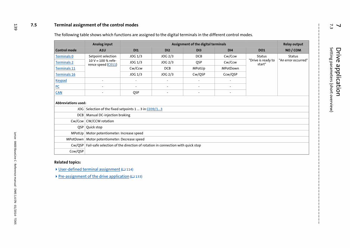
7D
rive application7.3
Setting param
eters (short overview
)
139Len
ze · 8400 BaseLin
e C · Referen
ce man
ual · D
MS 1.6 EN
· 01/2014 · TD05
_ _ _ _ _ _ _ _ _ _ _ _ _ _ _ _ _ _ _ _ _ _ _ _ _ _ _ _ _ _ _ _ _ _ _ _ _ _ _ _ _ _ _ _ _ _ _ _ _ _ _ _ _ _ _ _ _ _ _ _ _ _ _ _
7.5 Terminal assignment of the control modes
The following table shows which functions are assigned to the digital terminals in the different control modes.
Related topics:
User-defined terminal assignment ( 114)
Pre-assignment of the drive application ( 133)
Analog input Assignment of the digital terminals Relay output
Control mode A1U DI1 DI2 DI3 DI4 DO1 NO / COM
Terminals 0 Setpoint selection10 V ≡ 100 % refe-rence speed (C011)
JOG 1/3 JOG 2/3 DCB Cw/Ccw Status"Drive is ready to
start"
Status"An error occurred"
Terminals 2 JOG 1/3 JOG 2/3 QSP Cw/Ccw
Terminals 11 Cw/Ccw DCB MPotUp MPotDown
Terminals 16 JOG 1/3 JOG 2/3 Cw/QSP Ccw/QSP
Keypad - - - - -
PC - - - - -
CAN - QSP - - -
Abbreviations used:
JOG Selection of the fixed setpoints 1 ... 3 in C039/1...3
DCB Manual DC-injection braking
Cw/Ccw CW/CCW rotation
QSP Quick stop
MPotUp Motor potentiometer: Increase speed
MPotDown Motor potentiometer: Decrease speed
Cw/QSP Fail-safe selection of the direction of rotation in connection with quick stop
Ccw/QSP
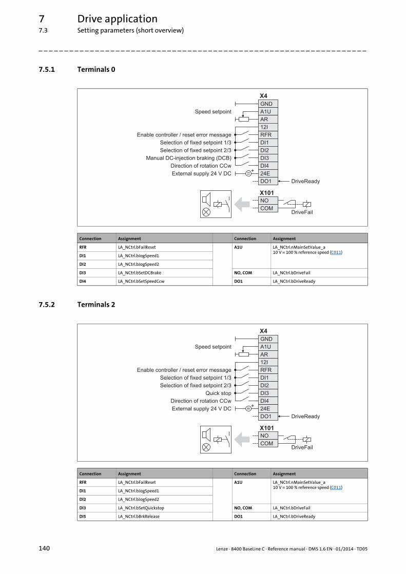
7 Drive application7.3 Setting parameters (short overview)
140 Lenze · 8400 BaseLine C · Reference manual · DMS 1.6 EN · 01/2014 · TD05
_ _ _ _ _ _ _ _ _ _ _ _ _ _ _ _ _ _ _ _ _ _ _ _ _ _ _ _ _ _ _ _ _ _ _ _ _ _ _ _ _ _ _ _ _ _ _ _ _ _ _ _ _ _ _ _ _ _ _ _ _ _ _ _
7.5.1 Terminals 0
7.5.2 Terminals 2
Connection Assignment Connection Assignment
RFR LA_NCtrl.bFailReset A1U LA_NCtrl.nMainSetValue_a 10 V ≡ 100 % reference speed (C011)
DI1 LA_NCtrl.bJogSpeed1
DI2 LA_NCtrl.bJogSpeed2
DI3 LA_NCtrl.bSetDCBrake NO, COM LA_NCtrl.bDriveFail
DI4 LA_NCtrl.bSetSpeedCcw DO1 LA_NCtrl.bDriveReady
X101
NO
COM
GND
A1U
AR
RFR
DI1
DI2
DI3
DI4
24E
DO1
12I
X4
+
Speed setpoint
Enable controller / reset error message
Selection of fixed setpoint 1/3
Selection of fixed setpoint 2/3
Manual DC-injection braking (DCB)
Direction of rotation CCw
External supply 24 V DC
DriveFail
DriveReady
Connection Assignment Connection Assignment
RFR LA_NCtrl.bFailReset A1U LA_NCtrl.nMainSetValue_a 10 V ≡ 100 % reference speed (C011)
DI1 LA_NCtrl.bJogSpeed1
DI2 LA_NCtrl.bJogSpeed2
DI3 LA_NCtrl.bSetQuickstop NO, COM LA_NCtrl.bDriveFail
DI5 LA_NCtrl.bBrkRelease DO1 LA_NCtrl.bDriveReady
X101
NO
COM
GND
A1U
AR
RFR
DI1
DI2
DI3
DI4
24E
DO1
12I
X4
+
Speed setpoint
Enable controller / reset error message
Selection of fixed setpoint 1/3
Selection of fixed setpoint 2/3
Quick stop
Direction of rotation CCw
External supply 24 V DC
DriveFail
DriveReady

Lenze · 8400 BaseLine C · Reference manual · DMS 1.6 EN · 01/2014 · TD05 141
7 Drive application7.3 Setting parameters (short overview)
_ _ _ _ _ _ _ _ _ _ _ _ _ _ _ _ _ _ _ _ _ _ _ _ _ _ _ _ _ _ _ _ _ _ _ _ _ _ _ _ _ _ _ _ _ _ _ _ _ _ _ _ _ _ _ _ _ _ _ _ _ _ _ _
7.5.3 Terminals 11
7.5.4 Terminals 16
Connection Assignment Connection Assignment
RFR LA_NCtrl.bFailReset A1U LA_NCtrl.nMainSetValue_a 10 V ≡ 100 % reference speed (C011)
DI1 LA_NCtrl.bSetSpeedCcw
DI2 LA_NCtrl.bSetDCBrake
DI3 LA_NCtrl.bMPotUp NO, COM LA_NCtrl.bDriveFail
DI4 LA_NCtrl.bMPotDown DO1 LA_NCtrl.bDriveReady
X101
NO
COM
GND
A1U
AR
RFR
DI1
DI2
DI3
DI4
24E
DO1
12I
X4
+
Speed setpoint
Enable controller / reset error message
Direction of rotation CCw
Manual DC-injection braking (DCB)
increase speed
decrease speed
External supply 24 V DC
Motor potentiometer
DriveFail
DriveReady
Connection Assignment Connection Assignment
RFR LA_NCtrl.bFailReset A1U LA_NCtrl.nMainSetValue_a 10 V ≡ 100 % reference speed (C011)
DI1 LA_NCtrl.bJogSpeed1
DI2 LA_NCtrl.bJogSpeed2
DI3 LA_NCtrl. bRLQCw NO, COM LA_NCtrl.bDriveFail
DI4 LA_NCtrl. bRLQCcw DO1 LA_NCtrl.bDriveReady
X101
NO
COM
GND
A1U
AR
RFR
DI1
DI2
DI3
DI4
24E
DO1
12I
X4
+
Speed setpoint
Enable controller / reset error message
Selection of fixed setpoint 1/3
Selection of fixed setpoint 2/3
Cw rotation - quick stop
CCw rotation - quick stop
External supply 24 V DC
DriveFail
DriveReady
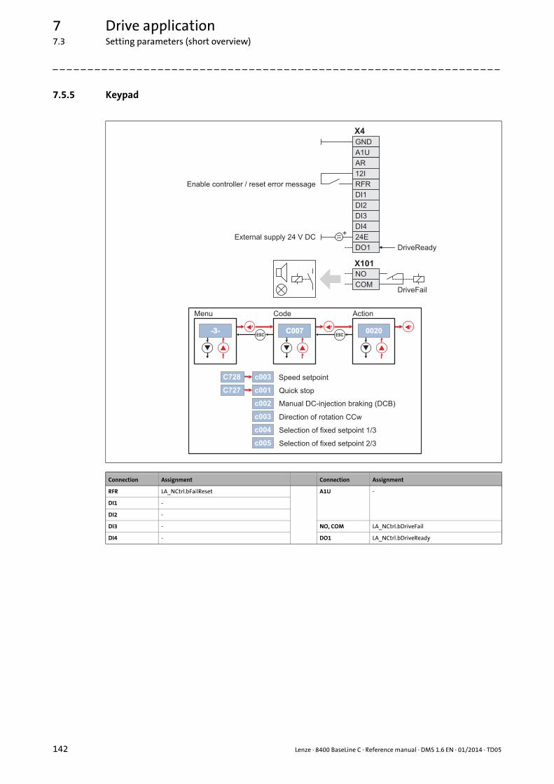
7 Drive application7.3 Setting parameters (short overview)
142 Lenze · 8400 BaseLine C · Reference manual · DMS 1.6 EN · 01/2014 · TD05
_ _ _ _ _ _ _ _ _ _ _ _ _ _ _ _ _ _ _ _ _ _ _ _ _ _ _ _ _ _ _ _ _ _ _ _ _ _ _ _ _ _ _ _ _ _ _ _ _ _ _ _ _ _ _ _ _ _ _ _ _ _ _ _
7.5.5 Keypad
Connection Assignment Connection Assignment
RFR LA_NCtrl.bFailReset A1U -
DI1 -
DI2 -
DI3 - NO, COM LA_NCtrl.bDriveFail
DI4 - DO1 LA_NCtrl.bDriveReady
X101
NO
COM
GND
A1U
AR
RFR
DI1
DI2
DI3
DI4
24E
DO1
12I
X4
+
c003
c002
c001
� �
-3--3-ESC
� � � �
C007C007 0020ESC
C728
C727
c003
c004
c005
Enable controller / reset error message
External supply 24 V DC
DriveFail
DriveReady
Speed setpoint
Selection of fixed setpoint 1/3
Selection of fixed setpoint 2/3
Manual DC-injection braking (DCB)
Direction of rotation CCw
Quick stop
Menu Code Action

Lenze · 8400 BaseLine C · Reference manual · DMS 1.6 EN · 01/2014 · TD05 143
7 Drive application7.3 Setting parameters (short overview)
_ _ _ _ _ _ _ _ _ _ _ _ _ _ _ _ _ _ _ _ _ _ _ _ _ _ _ _ _ _ _ _ _ _ _ _ _ _ _ _ _ _ _ _ _ _ _ _ _ _ _ _ _ _ _ _ _ _ _ _ _ _ _ _
7.5.6 PC
In this control mode, the control is executed via "free" parameters. The connection to inputs/out-puts of the application takes place via the following system blocks:
Connection Assignment Connection Assignment
RFR LA_NCtrl.bFailReset A1U -
DI1 -
DI2 -
DI3 - NO, COM LA_NCtrl.bDriveFail
DI4 - DO1 LA_NCtrl.bDriveReady
System block Function
LS_DisFree Any four 16-bit signals of the application can be displayed on display codes
LS_DisFree_a Any four analog signals of the application can be displayed on display codes
LS_DisFree_b Any eight digital signals of the application can be displayed on a bit-coded display code
LS_ParFree_a Output of 4 parameterisable analog signals
LS_ParFree_b Output of 16 parameterisable digital signals
X101
NO
COM
GND
A1U
AR
RFR
DI1
DI2
DI3
DI4
24E
DO1
12I
X4
+
C472/1
C470/3
C470/4
C470/1
C470/2
Enable controller / reset error message
External supply 24 V DC
DriveFail
DriveReady
Speed setpoint
Selection of fixed setpoint 1/3
Selection of fixed setpoint 2/3
Manual DC-injection braking (DCB)
Direction of rotation CCw

7 Drive application7.3 Setting parameters (short overview)
144 Lenze · 8400 BaseLine C · Reference manual · DMS 1.6 EN · 01/2014 · TD05
_ _ _ _ _ _ _ _ _ _ _ _ _ _ _ _ _ _ _ _ _ _ _ _ _ _ _ _ _ _ _ _ _ _ _ _ _ _ _ _ _ _ _ _ _ _ _ _ _ _ _ _ _ _ _ _ _ _ _ _ _ _ _ _
7.5.7 CAN
Related topics:
Process data assignment for control via CAN ( 137)
System bus "CAN on board" ( 169)
RPDO1 | Port block "LP_CanIn1" ( 185)
TPDO1 | Port block "LP_CanOut1" ( 187)
Connection Assignment Connection Assignment
RFR LA_NCtrl.bFailReset A1U -
DI1 LA_NCtrl.SetQuickstop
DI2 -
DI3 - NO, COM LA_NCtrl.bDriveFail
DI4 - DO1 LA_NCtrl.bDriveReady
The preconfigured interconnection of the internal interfaces in control mode "CAN" is shown in figure [7-2]. ( 136)
LP_CanIn1 LP_CanOut1
WORD 1
WORD 2
WORD 3
wCanControl
nMainSetValue_a
-
wDeviceStateWord
nMotorSpeedAct_a
nOutputSpeedCtrl_a
-WORD 4 -
WORD 1
WORD 2
WORD 3
WORD 4
X101
NO
COM
GND
A1U
AR
RFR
DI1
DI2
DI3
DI4
24E
DO1
12I
X4
+
X1
CH
CL
CG
Enable controller / reset error message
Quick stop
External supply 24 V DC
DriveFail
DriveReady

Lenze · 8400 BaseLine C · Reference manual · DMS 1.6 EN · 01/2014 · TD05 145
8 Diagnostics & error management8.1 Basics on error handling in the controller
_ _ _ _ _ _ _ _ _ _ _ _ _ _ _ _ _ _ _ _ _ _ _ _ _ _ _ _ _ _ _ _ _ _ _ _ _ _ _ _ _ _ _ _ _ _ _ _ _ _ _ _ _ _ _ _ _ _ _ _ _ _ _ _
8 Diagnostics & error management
This chapter provides information on error handling, drive diagnostics, and fault analysis.
8.1 Basics on error handling in the controller
Many of the functions integrated into the controller can
• detect errors and thus protect the device from damage or overload, e.g. short-circuit detection, Ixt overload detection, overtemperature detection, etc.
• detect operating errors by the user, e.g. a missing memory module,
• output warning signals, e.g. if the speed is too high or too low, etc.
Depending on the importance, the error detection in the device responds very fast (e.g. short-circuitdetection < 1 ms) or in a slower cycle (e.g. temperature monitoring approx. 100 ms).
All functions provided with an error detection (e.g. the motor control) supply information to a so-called error handler. The error handler is processed every 1 ms and evaluates all information.
In this evaluation, the current error (display in C165) is generated and the controller is caused to takethe respective error status (e.g. trouble.
The error information in C166/1..3 is used for error diagnosis and contains the following informati-on:
1. Error type (e.g. "Warning")
2. Error subject area (e.g. "motor management/encoder")
3. The error ID within the error subject area
Together all types of information form the real error number which is unique in the whole devicesystem.Structure of the error number (bit coding) ( 156)
In addition to the control of the device state by the error handler, a logbook function records the er-rors and their histories. Logbook ( 149)
Tip!
For many device errors, the error type and hence the response of the controller to the errorcan be parameterised. Setting the error response ( 153)
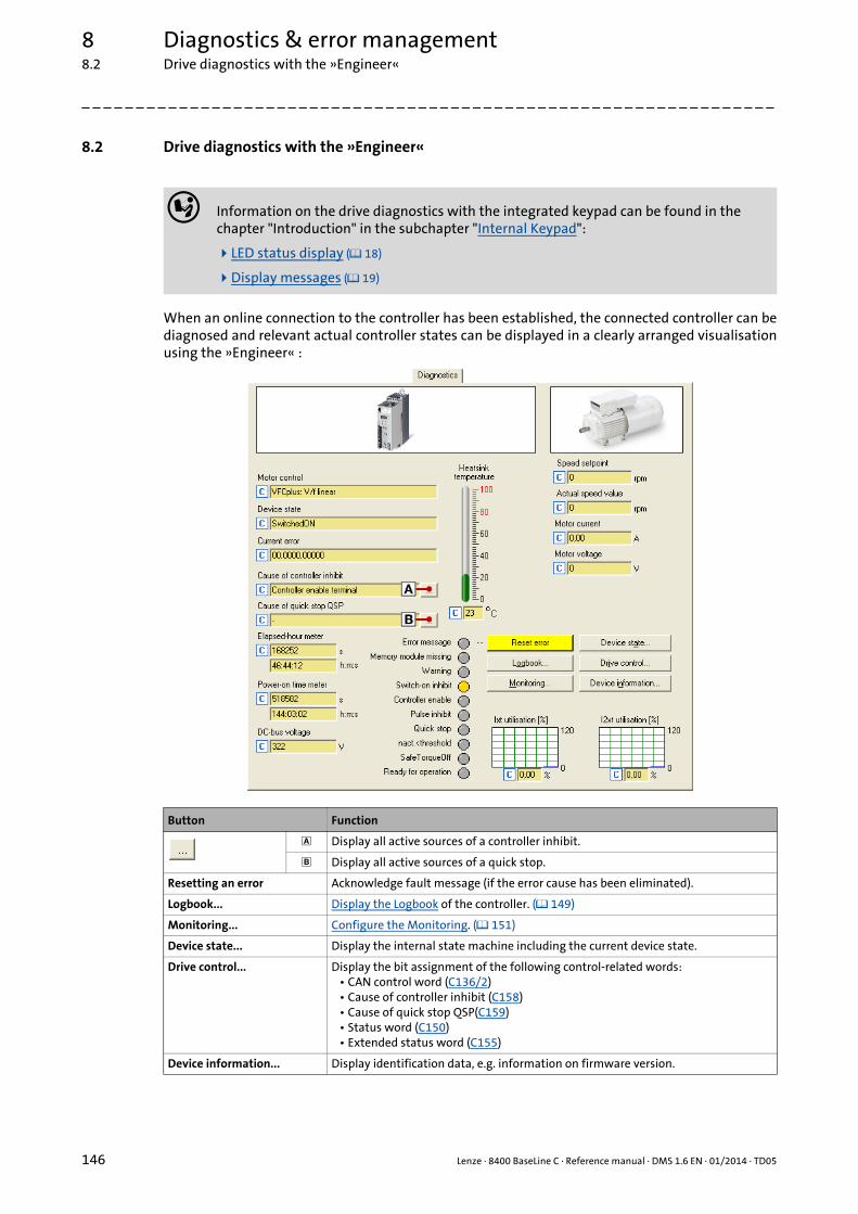
8 Diagnostics & error management8.2 Drive diagnostics with the »Engineer«
146 Lenze · 8400 BaseLine C · Reference manual · DMS 1.6 EN · 01/2014 · TD05
_ _ _ _ _ _ _ _ _ _ _ _ _ _ _ _ _ _ _ _ _ _ _ _ _ _ _ _ _ _ _ _ _ _ _ _ _ _ _ _ _ _ _ _ _ _ _ _ _ _ _ _ _ _ _ _ _ _ _ _ _ _ _ _
8.2 Drive diagnostics with the »Engineer«
When an online connection to the controller has been established, the connected controller can bediagnosed and relevant actual controller states can be displayed in a clearly arranged visualisationusing the »Engineer« :
Information on the drive diagnostics with the integrated keypad can be found in the chapter "Introduction" in the subchapter "Internal Keypad":
LED status display ( 18)
Display messages ( 19)
Button Function
Display all active sources of a controller inhibit.
Display all active sources of a quick stop.
Resetting an error Acknowledge fault message (if the error cause has been eliminated).
Logbook... Display the Logbook of the controller. ( 149)
Monitoring... Configure the Monitoring. ( 151)
Device state... Display the internal state machine including the current device state.
Drive control... Display the bit assignment of the following control-related words:• CAN control word (C136/2)• Cause of controller inhibit (C158)• Cause of quick stop QSP(C159)• Status word (C150)• Extended status word (C155)
Device information... Display identification data, e.g. information on firmware version.

Lenze · 8400 BaseLine C · Reference manual · DMS 1.6 EN · 01/2014 · TD05 147
8 Diagnostics & error management8.2 Drive diagnostics with the »Engineer«
_ _ _ _ _ _ _ _ _ _ _ _ _ _ _ _ _ _ _ _ _ _ _ _ _ _ _ _ _ _ _ _ _ _ _ _ _ _ _ _ _ _ _ _ _ _ _ _ _ _ _ _ _ _ _ _ _ _ _ _ _ _ _ _
How to diagnose a drive with the »Engineer«:
1. Go to the Project view and select the 8400 BaseLine C controller.
2. Click the icon or execute the OnlineGo online command to establish an online con-nection to the controller.
3. Select the Diagnostics tab.• With an online connection, the Diagnostics tab displays current status information
about the controller.
Related topics:
Device control (DCTRL) ( 44)
Device states ( 53)

8 Diagnostics & error management8.3 Drive diagnostics via bus system
148 Lenze · 8400 BaseLine C · Reference manual · DMS 1.6 EN · 01/2014 · TD05
_ _ _ _ _ _ _ _ _ _ _ _ _ _ _ _ _ _ _ _ _ _ _ _ _ _ _ _ _ _ _ _ _ _ _ _ _ _ _ _ _ _ _ _ _ _ _ _ _ _ _ _ _ _ _ _ _ _ _ _ _ _ _ _
8.3 Drive diagnostics via bus system
The following display parameters contain actual values, states, and error messages.
• These parameters are listed in the »Engineer« parameter list in the Diagnostics category.
• A detailed description of these parameters can be found in the chapter "Parameter reference" ( 228).
Parameter Display
C051 MCTRL: Actual speed value
C052 Motor voltage
C053 DC-bus voltage
C054 Motor current
C056/1 Torque setpoint
C056/2 Actual torque
C058 Output frequency
C059 Appl.: Reference frequency C11
C061 Heatsink temperature
C064/1 Device utilisation (Ixt)
C064/2 Device utilisation (Ixt) 15s
C064/3 Device utilisation (Ixt) 3 min
C136/2 CAN control word
C137 Device state
C150 Status word
C155 Status word 2
C158 Cause of controller inhibit
C159 Cause of quick stop QSP
C165/1 Current error
C166/1 Error type, current
C166/2 Error subject area, current
C166/3 Error ID, current
C168/1...8 Error ID, history 1 ... 8
C169/1...8 Time of error, history 1 ... 8
C170/1...8 Error counter, history 1 ... 8
C177/1 Switching cycles mains switching
C177/2 Switching cycles output relay
C178 Time the controller was enabled (elapsed-hour meter)
C179 Power-up time (power-on time meter)
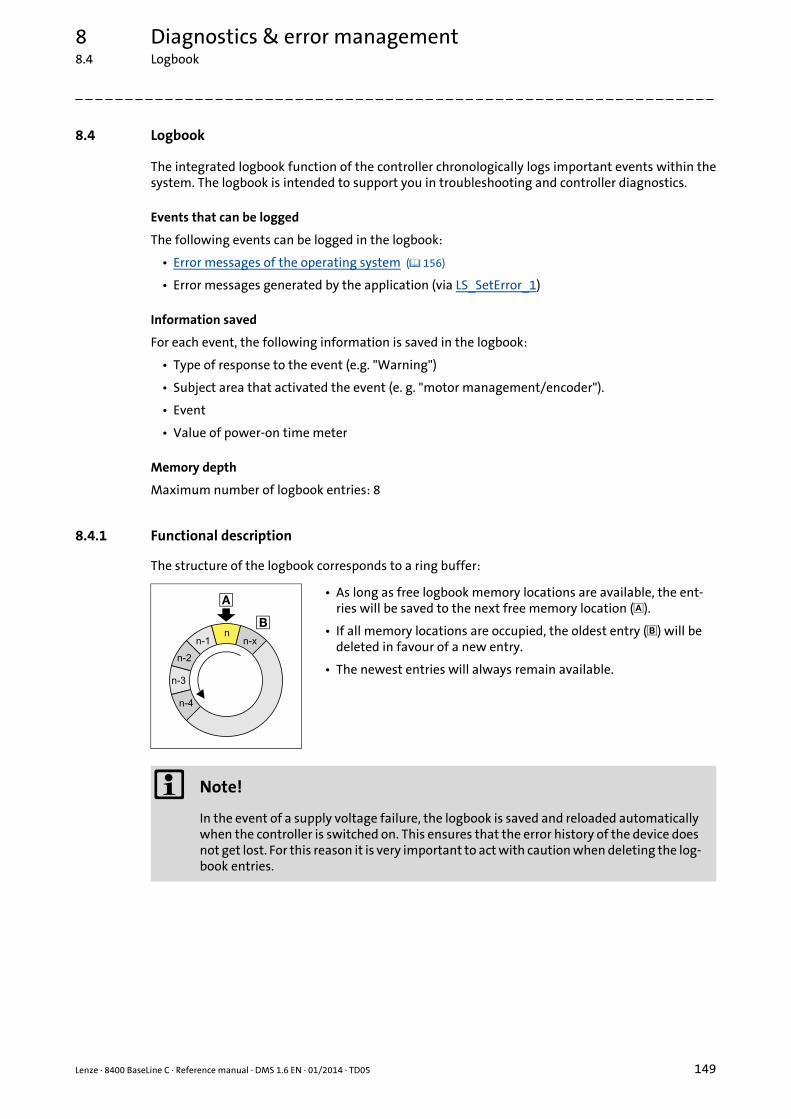
Lenze · 8400 BaseLine C · Reference manual · DMS 1.6 EN · 01/2014 · TD05 149
8 Diagnostics & error management8.4 Logbook
_ _ _ _ _ _ _ _ _ _ _ _ _ _ _ _ _ _ _ _ _ _ _ _ _ _ _ _ _ _ _ _ _ _ _ _ _ _ _ _ _ _ _ _ _ _ _ _ _ _ _ _ _ _ _ _ _ _ _ _ _ _ _ _
8.4 Logbook
The integrated logbook function of the controller chronologically logs important events within thesystem. The logbook is intended to support you in troubleshooting and controller diagnostics.
Events that can be logged
The following events can be logged in the logbook:
• Error messages of the operating system ( 156)
• Error messages generated by the application (via LS_SetError_1)
Information saved
For each event, the following information is saved in the logbook:
• Type of response to the event (e.g. "Warning")
• Subject area that activated the event (e. g. "motor management/encoder").
• Event
• Value of power-on time meter
Memory depth
Maximum number of logbook entries: 8
8.4.1 Functional description
The structure of the logbook corresponds to a ring buffer:
• As long as free logbook memory locations are available, the ent-ries will be saved to the next free memory location ().
• If all memory locations are occupied, the oldest entry () will be deleted in favour of a new entry.
• The newest entries will always remain available.
Note!
In the event of a supply voltage failure, the logbook is saved and reloaded automatically when the controller is switched on. This ensures that the error history of the device does not get lost. For this reason it is very important to act with caution when deleting the log-book entries.
8 Diagnostics & error management8.4 Logbook
150 Lenze · 8400 BaseLine C · Reference manual · DMS 1.6 EN · 01/2014 · TD05
_ _ _ _ _ _ _ _ _ _ _ _ _ _ _ _ _ _ _ _ _ _ _ _ _ _ _ _ _ _ _ _ _ _ _ _ _ _ _ _ _ _ _ _ _ _ _ _ _ _ _ _ _ _ _ _ _ _ _ _ _ _ _ _
8.4.2 Reading out logbook entries
We recommend to read out logbook entries with the »Engineer«, since the »Engineer« shows theentries clearly arranged and enables them to be exported into a log file. Alternatively, the corres-ponding parameters can be read out using the keypad or via the fieldbus.
How to display logbook entries in the »Engineer«:
1. Go to the Project view and select the 8400 BaseLine C controller.
2. Click the icon or execute the OnlineGo online command to establish an online con-nection to the controller.
3. Select the Diagnostics tab from the Workspace.
4. Click Logbook.• The Logbook dialog box with logbook entries is displayed.• Click Delete to delete an entry from the logbook.• Click Export to export the entries from the logbook into a *.log file.Exporting logbook
entries to a file ( 150)
5. Click the Close button to close the Logbook dialog box again.
8.4.3 Exporting logbook entries to a file
How to export the logbook entries to a file:
1. Go to the Logbook dialog box and click the Export... button.• The Export logbook dialog box is displayed.
2. Specify the folder, file name, and file type for the file.
3. Click the Save button to export the logbook entries to the specified file.• Hidden logbook entries are not exported, i.e. the filter criteria specified are accounted for
during the export.• The logbook entries are written to the file in the form of a semicolon separated list.
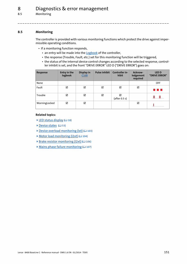
Lenze · 8400 BaseLine C · Reference manual · DMS 1.6 EN · 01/2014 · TD05 151
8 Diagnostics & error management8.5 Monitoring
_ _ _ _ _ _ _ _ _ _ _ _ _ _ _ _ _ _ _ _ _ _ _ _ _ _ _ _ _ _ _ _ _ _ _ _ _ _ _ _ _ _ _ _ _ _ _ _ _ _ _ _ _ _ _ _ _ _ _ _ _ _ _ _
8.5 Monitoring
The controller is provided with various monitoring functions which protect the drive against imper-missible operating conditions.
• If a monitoring function responds,• an entry will be made into the Logbook of the controller,• the response (Trouble, Fault, etc.) set for this monitoring function will be triggered,• the status of the internal device control changes according to the selected response, control-
ler inhibit is set, and the front "DRIVE ERROR" LED D ("DRIVE ERROR") goes on:
Related topics:
LED status display ( 18)
Device states ( 53)
Device overload monitoring (Ixt) ( 103)
Motor load monitoring (I2xt) ( 104)
Brake resistor monitoring (I2xt) ( 106)
Mains phase failure monitoring ( 107)
Response Entry in the logbook
Display in C168
Pulse inhibit Controller in-hibit
Acknow-ledgement
required
LED D"DRIVE ERROR"
None OFF
Fault
Trouble (after 0.5 s)
WarningLocked
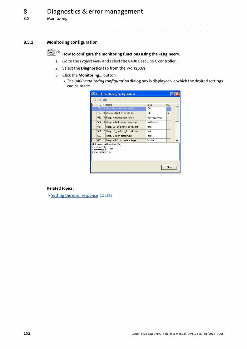
8 Diagnostics & error management8.5 Monitoring
152 Lenze · 8400 BaseLine C · Reference manual · DMS 1.6 EN · 01/2014 · TD05
_ _ _ _ _ _ _ _ _ _ _ _ _ _ _ _ _ _ _ _ _ _ _ _ _ _ _ _ _ _ _ _ _ _ _ _ _ _ _ _ _ _ _ _ _ _ _ _ _ _ _ _ _ _ _ _ _ _ _ _ _ _ _ _
8.5.1 Monitoring configuration
How to configure the monitoring functions using the »Engineer«:
1. Go to the Project view and select the 8400 BaseLine C controller.
2. Select the Diagnostics tab from the Workspace.
3. Click the Monitoring... button.• The 8400 monitoring configuration dialog box is displayed via which the desired settings
can be made:
Related topics:
Setting the error response ( 153)

Lenze · 8400 BaseLine C · Reference manual · DMS 1.6 EN · 01/2014 · TD05 153
8 Diagnostics & error management8.5 Monitoring
_ _ _ _ _ _ _ _ _ _ _ _ _ _ _ _ _ _ _ _ _ _ _ _ _ _ _ _ _ _ _ _ _ _ _ _ _ _ _ _ _ _ _ _ _ _ _ _ _ _ _ _ _ _ _ _ _ _ _ _ _ _ _ _
8.5.2 Setting the error response
When a monitoring function responds, the response set for this monitoring function (Trouble, Fault,etc.) will be triggered.
• For many monitoring functions the response can be individually parameterised via parameters.
Tip!
The table in chapter "Short overview (A-Z)" contains the error messages for which the re-sponse can be set . ( 159)
Warning thresholds
Some of the monitoring functions are activated if a defined warning threshold has been exceeded.
• The corresponding preset threshold values can be changed via the following parameters:
Parameter Info Lenze setting
Value Unit
C120 Motor overload threshold (I²xt) 100 %
C123 Device utilisat. threshold (Ixt) 100 %
C909/1 Max. positive speed 120 %
C909/2 Max. negative speed 120 %
C910/1 Max. positive output frequency 300 Hz
C910/2 Max. negative output frequency 300 Hz

8 Diagnostics & error management8.6 Maloperation of the drive
154 Lenze · 8400 BaseLine C · Reference manual · DMS 1.6 EN · 01/2014 · TD05
_ _ _ _ _ _ _ _ _ _ _ _ _ _ _ _ _ _ _ _ _ _ _ _ _ _ _ _ _ _ _ _ _ _ _ _ _ _ _ _ _ _ _ _ _ _ _ _ _ _ _ _ _ _ _ _ _ _ _ _ _ _ _ _
8.6 Maloperation of the drive
Maloperation Cause Remedy
Motor does not rota-te
DC-bus voltage is too low• Red LED is blinking every 1 s
Check mains voltage
Controller is inhibited• Green LED is blinking
Deactivate controller inhibit• Note: Controller inhibit can be set via se-
veral sources !• C158 displays all active sources for cont-
roller inhibit.
Automatic start is inhibited LOW/HIGH edge at RFRIf required, correct auto-start option in C142."Inhibit at power-on" auto-start option
DC-injection braking (DCB) is active Deactivate DC-injection braking
Mechanical motor brake is not released Release mechanical motor brake manually or electrically
Quick stop (QSP) active Deactivate quick stop• Note: Quick stop can be set via several
sources!• C159 displays all active sources for quick
stop.
Setpoint = 0 Select setpoint
Setpoint = 0 with activated fixed setpoint Set fixed setpoint in C039/1...3
Trouble is active Clear fault
With C006 = 4 zwar "SLVC: Vector control" has been set, but no motor parameter identi-fication has been carried out.
Carry out automatic motor parameter identi-fication with the C002/23 device command.Automatic motor data identification
Assignment of several mutually exclusive functions with a signal source in C701
Correct configuration in C701.
Motor rotates irregu-larly
Motor cable is defective Check motor cable
Maximum motor current in motor or genera-tor mode is set too low
Adjust settings to the application: C022: Imax in motor modeC023: Imax in generator mode
Motor is underexcited or overexcited Check parameterisation:C006: Motor controlC015: VFC: V/f base frequencyC016: VFC: Vmin boost
Rated motor data (stator resistance, speed, current, frequency, voltage) and cos ϕ and/or magnetising inductance is not adapted to the motor data
Carry out automatic motor parameter identi-fication with the C002/23 device command- or -Adjust motor parameters manually:C084: Motor stator resistanceC087: Rated motor speedC088: Rated motor currentC089: Rated motor frequencyC090: Rated motor voltageC091: Motor cosine phiC092: Motor magnetising inductance
Motor windings are wired incorrectly Reverse from star connection to delta con-nection
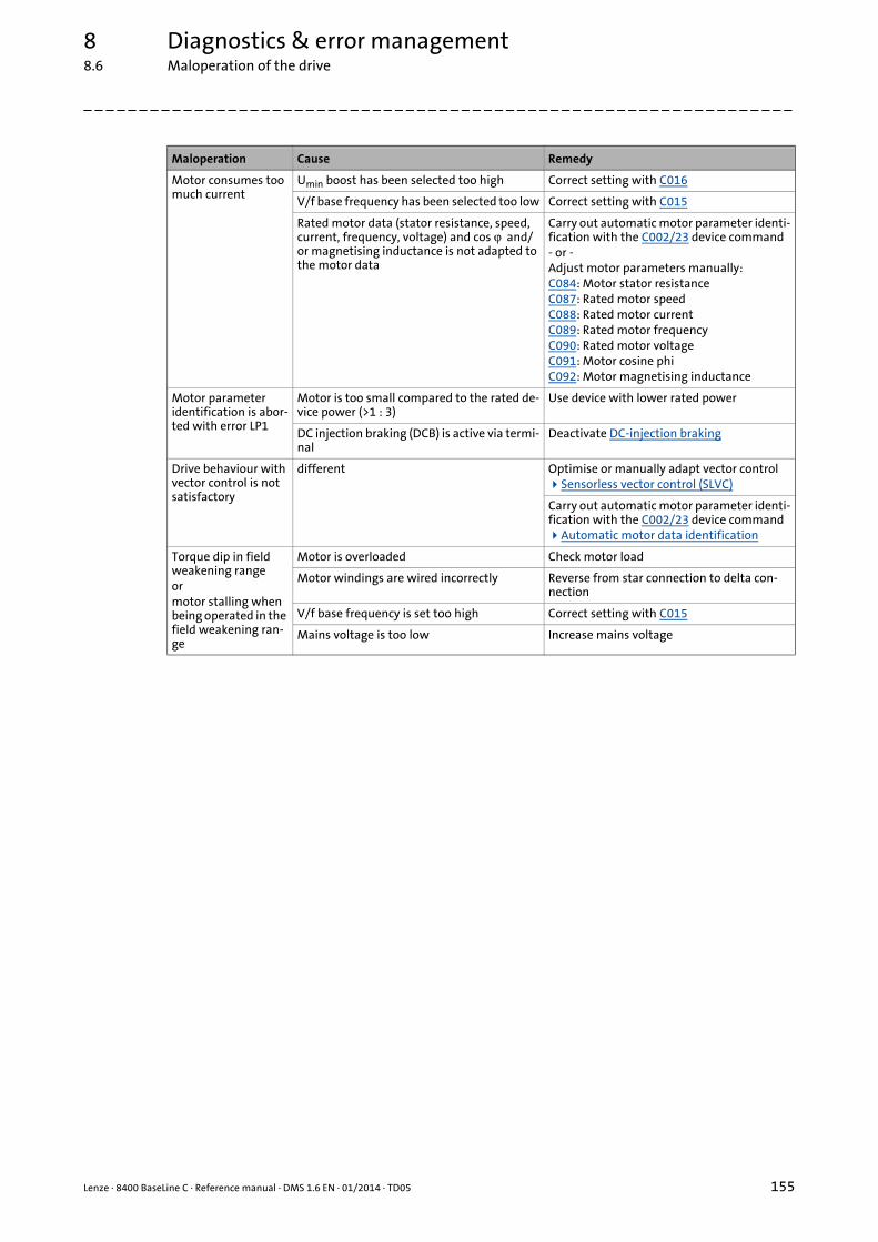
Lenze · 8400 BaseLine C · Reference manual · DMS 1.6 EN · 01/2014 · TD05 155
8 Diagnostics & error management8.6 Maloperation of the drive
_ _ _ _ _ _ _ _ _ _ _ _ _ _ _ _ _ _ _ _ _ _ _ _ _ _ _ _ _ _ _ _ _ _ _ _ _ _ _ _ _ _ _ _ _ _ _ _ _ _ _ _ _ _ _ _ _ _ _ _ _ _ _ _
Motor consumes too much current
Umin boost has been selected too high Correct setting with C016
V/f base frequency has been selected too low Correct setting with C015
Rated motor data (stator resistance, speed, current, frequency, voltage) and cos ϕ and/or magnetising inductance is not adapted to the motor data
Carry out automatic motor parameter identi-fication with the C002/23 device command- or -Adjust motor parameters manually:C084: Motor stator resistanceC087: Rated motor speedC088: Rated motor currentC089: Rated motor frequencyC090: Rated motor voltageC091: Motor cosine phiC092: Motor magnetising inductance
Motor parameter identification is abor-ted with error LP1
Motor is too small compared to the rated de-vice power (>1 : 3)
Use device with lower rated power
DC injection braking (DCB) is active via termi-nal
Deactivate DC-injection braking
Drive behaviour with vector control is not satisfactory
different Optimise or manually adapt vector controlSensorless vector control (SLVC)
Carry out automatic motor parameter identi-fication with the C002/23 device commandAutomatic motor data identification
Torque dip in field weakening rangeormotor stalling when being operated in the field weakening ran-ge
Motor is overloaded Check motor load
Motor windings are wired incorrectly Reverse from star connection to delta con-nection
V/f base frequency is set too high Correct setting with C015
Mains voltage is too low Increase mains voltage
Maloperation Cause Remedy
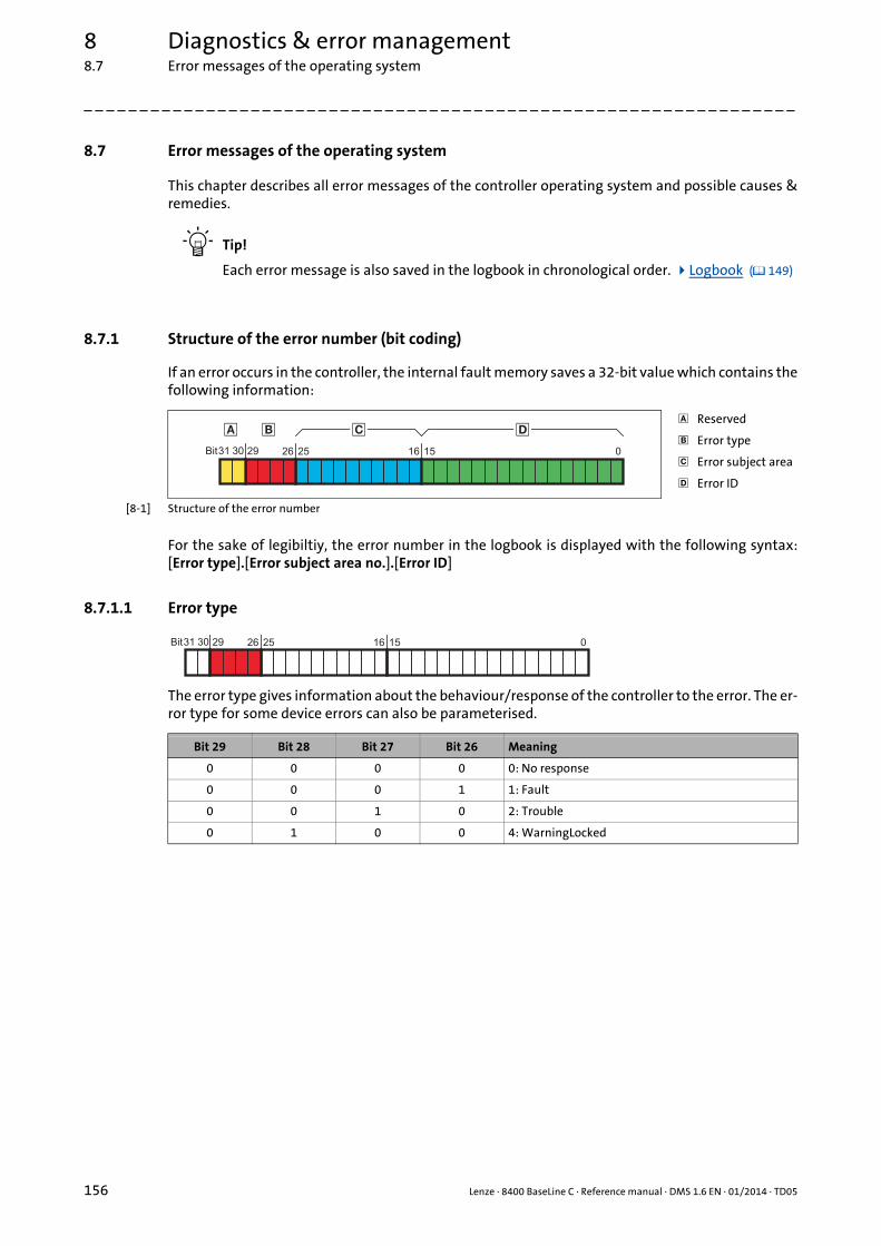
8 Diagnostics & error management8.7 Error messages of the operating system
156 Lenze · 8400 BaseLine C · Reference manual · DMS 1.6 EN · 01/2014 · TD05
_ _ _ _ _ _ _ _ _ _ _ _ _ _ _ _ _ _ _ _ _ _ _ _ _ _ _ _ _ _ _ _ _ _ _ _ _ _ _ _ _ _ _ _ _ _ _ _ _ _ _ _ _ _ _ _ _ _ _ _ _ _ _ _
8.7 Error messages of the operating system
This chapter describes all error messages of the controller operating system and possible causes &remedies.
Tip!
Each error message is also saved in the logbook in chronological order. Logbook ( 149)
8.7.1 Structure of the error number (bit coding)
If an error occurs in the controller, the internal fault memory saves a 32-bit value which contains thefollowing information:
[8-1] Structure of the error number
For the sake of legibiltiy, the error number in the logbook is displayed with the following syntax:[Error type].[Error subject area no.].[Error ID]
8.7.1.1 Error type
The error type gives information about the behaviour/response of the controller to the error. The er-ror type for some device errors can also be parameterised.
Reserved
Error type
Error subject area
Error ID
��� �
Bit 16252631 0152930
Bit 29 Bit 28 Bit 27 Bit 26 Meaning
0 0 0 0 0: No response
0 0 0 1 1: Fault
0 0 1 0 2: Trouble
0 1 0 0 4: WarningLocked
Bit 16252631 0152930
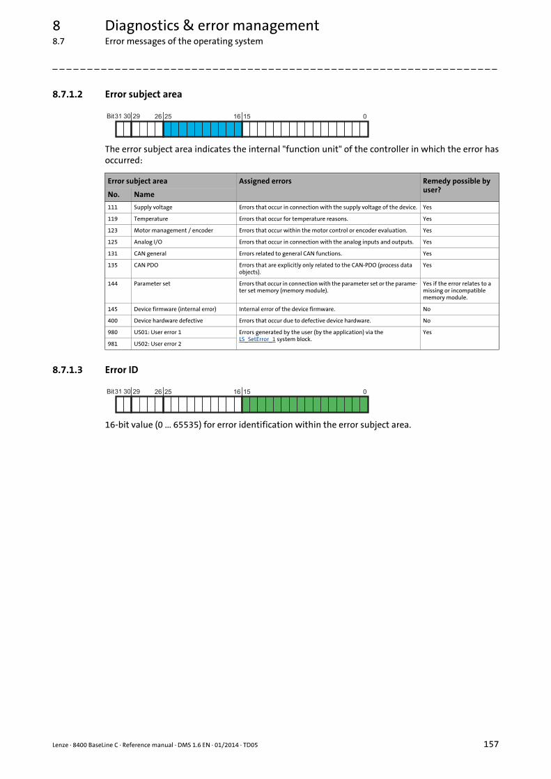
Lenze · 8400 BaseLine C · Reference manual · DMS 1.6 EN · 01/2014 · TD05 157
8 Diagnostics & error management8.7 Error messages of the operating system
_ _ _ _ _ _ _ _ _ _ _ _ _ _ _ _ _ _ _ _ _ _ _ _ _ _ _ _ _ _ _ _ _ _ _ _ _ _ _ _ _ _ _ _ _ _ _ _ _ _ _ _ _ _ _ _ _ _ _ _ _ _ _ _
8.7.1.2 Error subject area
The error subject area indicates the internal "function unit" of the controller in which the error hasoccurred:
8.7.1.3 Error ID
16-bit value (0 ... 65535) for error identification within the error subject area.
Error subject area Assigned errors Remedy possible by user?
No. Name
111 Supply voltage Errors that occur in connection with the supply voltage of the device. Yes
119 Temperature Errors that occur for temperature reasons. Yes
123 Motor management / encoder Errors that occur within the motor control or encoder evaluation. Yes
125 Analog I/O Errors that occur in connection with the analog inputs and outputs. Yes
131 CAN general Errors related to general CAN functions. Yes
135 CAN PDO Errors that are explicitly only related to the CAN-PDO (process data objects).
Yes
144 Parameter set Errors that occur in connection with the parameter set or the parame-ter set memory (memory module).
Yes if the error relates to a missing or incompatible memory module.
145 Device firmware (internal error) Internal error of the device firmware. No
400 Device hardware defective Errors that occur due to defective device hardware. No
980 US01: User error 1 Errors generated by the user (by the application) via the LS_SetError_1 system block.
Yes
981 US02: User error 2
Bit 16252631 0152930
Bit 16252631 0152930

8 Diagnostics & error management8.7 Error messages of the operating system
158 Lenze · 8400 BaseLine C · Reference manual · DMS 1.6 EN · 01/2014 · TD05
_ _ _ _ _ _ _ _ _ _ _ _ _ _ _ _ _ _ _ _ _ _ _ _ _ _ _ _ _ _ _ _ _ _ _ _ _ _ _ _ _ _ _ _ _ _ _ _ _ _ _ _ _ _ _ _ _ _ _ _ _ _ _ _
8.7.1.4 Example for bit coding of the error number
In C168 displays the internal error number "75169803.
• This decimal value corresponds to the following bit sequence:
• Thus, error number "75169803" means:An overcurrent has been detected in the "Motor management/encoder" subject area. A pulse in-hibit is set as error response. The error message must be acknowledged after the error has been eliminated.
8.7.2 Reset of error message
An error message with the response "Fault", "Trouble", or "Warning locked" must be explicitly reset(acknowledged) after the cause of the error has been eliminated.
To reset (acknowledge) a pending error message, execute the device command C002/19 = "1" .
Tip!
With an online connection to the controller, use the Diagnostics tab of the »Engineer« andclick Error message reset to reset a pending error message.
Assignment Information Meaning in the example
Reserved -
Error type 1: Fault (pulse inhibit)
Error subject area 123: Motor management / encoder
Error ID 13: "LU: DC bus undervoltage"
��� �
Bit 16252631 0152930
0 0 0 0 0 1 0 0 0 1 1 1 1 0 1 1 0 0 0 0 0 0 0 0 0 0 1 1 0 100
0 0
0 0 0 1
0 0 0 1 1 1 1 0 1 1
0 0 0 0 0 0 0 0 0 0 1 0 1 100

Lenze · 8400 BaseLine C · Reference manual · DMS 1.6 EN · 01/2014 · TD05 159
8 Diagnostics & error management8.7 Error messages of the operating system
_ _ _ _ _ _ _ _ _ _ _ _ _ _ _ _ _ _ _ _ _ _ _ _ _ _ _ _ _ _ _ _ _ _ _ _ _ _ _ _ _ _ _ _ _ _ _ _ _ _ _ _ _ _ _ _ _ _ _ _ _ _ _ _
8.7.3 Short overview (A-Z)
The table below contains all error messages of the controller operating system in alphabetical order.
Tip!
If you click the cross-reference in the first column, "Error number", you get to the detaileddescription of the respective error message in the subsequent "Cause & possible remedies"chapter . ( 161)
Note!
For the sake of legibility, the Logbook and C165 display the error number with the follo-wing syntax:[Error type].[Error subject area no.].[.].[Error ID]
In this documentation, "xx", a wildcard, stands for the error type since it is configurable for many error messages.
Error number Error message Response (Lenze setting)
can be set in CAN Emergency Error Code
xx.0125.00001 An01: AIN1_I < 4 mA Fault C598/1 0xF000
xx.0131.00006 CA06: CAN CRC error No response C592/1 0x8000
xx.0131.00007 CA07: CAN Bus Warn No response C592/3 0x8000
xx.0131.00008 CA08: CAN Bus Stopped No response C592/4 0x8000
xx.0131.00011 CA0b: CAN Bus Live Time No response C592/5 0x8130
xx.0131.00015 CA0F: CAN control word No response C594/2 0xF000
xx.0135.00001 CE1: CAN RPDO1 No response C593/1 0x8100
xx.0135.00002 CE2: CAN RPDO2 No response C593/2 0x8100
xx.0131.00000 CE4: CAN Bus Off No response C592/2 0x8000
xx.0145.00001 dF01: Internal error 01 Fault -
xx.0145.00002 dF02: Internal error 02 Fault -
xx.0145.00003 dF03: Internal error 03 Fault -
xx.0145.00004 dF04: Internal error 04 Fault -
xx.0145.00005 dF05: Internal error 05 Fault -
xx.0145.00006 dF06: Internal error 06 Fault -
xx.0145.00007 dF07: Internal error 07 Fault -
xx.0145.00008 dF08: Internal error 08 Fault -
xx.0145.00009 dF09: Internal error 09 Fault -
xx.0145.00010 dF10: Internal error 10 Fault -
xx.0400.00105 dH69: Adjustment data error Fault - 0x5530
xx.0123.00057 ID1: Motor data identification error WarningLocked - 0xF000
xx.0123.00015 LU: DC bus undervoltage Trouble C600/1 0x3100
xx.0123.00016 OC1: Power section - short circuit Fault - 0x2000
xx.0123.00017 OC2: Power section - earth fault Fault - 0x2000
xx.0119.00050 OC5: Ixt overload WarningLocked C604 0x2000
xx.0123.00105 OC6: I2xt motor overload WarningLocked C606 0x2000
xx.0119.00052 OC9: Ixt overload - shutdown limit Fault - 0x2000
xx.0123.00065 OC12: I2xt brake resistance overload Fault - 0xF000
xx.0119.00001 OH: Heatsink overtemperature Fault - 0x4000
xx.0123.00014 OU: DC bus overvoltage Trouble - 0x3100
xx.0144.00001 PS01: No memory module Warning - 0x6300
xx.0144.00002 PS02: Par. set invalid Fault - 0x6300

8 Diagnostics & error management8.7 Error messages of the operating system
160 Lenze · 8400 BaseLine C · Reference manual · DMS 1.6 EN · 01/2014 · TD05
_ _ _ _ _ _ _ _ _ _ _ _ _ _ _ _ _ _ _ _ _ _ _ _ _ _ _ _ _ _ _ _ _ _ _ _ _ _ _ _ _ _ _ _ _ _ _ _ _ _ _ _ _ _ _ _ _ _ _ _ _ _ _ _
xx.0144.00003 PS03: Par. set device invalid Fault - 0x6300
xx.0144.00004 PS04: Par. set device incompatible Fault - 0x6300
xx.0144.00031 PS31: Ident. error Fault - 0x6300
xx.0111.00002 Su02: One mains phase is missing WarningLocked C565 0x3000
xx.0980.00000 US01: User error 1 Fault C581/1 0x6200
xx.0981.00000 US02: User error 2 Fault C581/2 0x6200
Error number Error message Response (Lenze setting)
can be set in CAN Emergency Error Code

Lenze · 8400 BaseLine C · Reference manual · DMS 1.6 EN · 01/2014 · TD05 161
8 Diagnostics & error management8.7 Error messages of the operating system
_ _ _ _ _ _ _ _ _ _ _ _ _ _ _ _ _ _ _ _ _ _ _ _ _ _ _ _ _ _ _ _ _ _ _ _ _ _ _ _ _ _ _ _ _ _ _ _ _ _ _ _ _ _ _ _ _ _ _ _ _ _ _ _
8.7.4 Cause & possible remedies
This chapter contains all error messages of the controller operating system in numerical order of theerror numbers. The list provides detailed information on the response to the error message as wellas information on the cause & possible remedies.
Tip!
A list of all error messages of the controller operating system in alphabetical order can befound in the previous chapter "Short overview (A-Z)" ( 159).
Su02: One mains phase is missing [xx.0111.00002]
OH: Heatsink overtemperature [xx.0119.00001]
OC5: Ixt overload [xx.0119.00050]
Note!
For the sake of legibility, the Logbook and C165 display the error number with the follo-wing syntax:[Error type].[Error subject area no.].[.].[Error ID]
In this documentation, "xx", a wildcard, stands for the error type since it is configurable for many error messages.
Response (Lenze setting printed in bold) Setting: C565 ( Adjustable response)
None Fault Trouble WarningLocked
Cause Remedy
One mains phase of a three-phase supply has failed. Check mains connection (terminal X100).
Response (Lenze setting printed in bold)
None Fault Trouble WarningLocked
Cause Remedy
The heatsink temperature is higher than the fixed limit temperature (90 ° C).Maybe the ambient temperature of the controller is too high or the fan or its ventilation slots are dirty.
• Check control cabinet temperature.• Clean filter.• Clean controller.• If required, clean or replace the fan.• Provide for sufficient cooling of the device.
Response (Lenze setting printed in bold) Setting: C604 ( Adjustable response)
None Fault Trouble WarningLocked
Cause Remedy
The Ixt overload check has tripped.• Operating threshold = 100 % Ixt (adjustable in C123)
Possible causes:• Wrong dimensioning of the device with regard to its
motor load.• Load cycles are not complied with.
• Check and, if required, correct dimensioning of the device and the motor load with regard to technical data.
• Reduce motor load cycles (observe load cycles accor-ding to documentation).
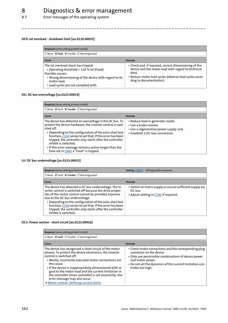
8 Diagnostics & error management8.7 Error messages of the operating system
162 Lenze · 8400 BaseLine C · Reference manual · DMS 1.6 EN · 01/2014 · TD05
_ _ _ _ _ _ _ _ _ _ _ _ _ _ _ _ _ _ _ _ _ _ _ _ _ _ _ _ _ _ _ _ _ _ _ _ _ _ _ _ _ _ _ _ _ _ _ _ _ _ _ _ _ _ _ _ _ _ _ _ _ _ _ _
OC9: Ixt overload - shutdown limit [xx.0119.00052]
OU: DC bus overvoltage [xx.0123.00014]
LU: DC bus undervoltage [xx.0123.00015]
OC1: Power section - short circuit [xx.0123.00016]
Response (Lenze setting printed in bold)
None Fault Trouble WarningLocked
Cause Remedy
The Ixt overload check has tripped.• Operating threshold = 110 % Ixt (fixed)
Possible causes:• Wrong dimensioning of the device with regard to its
motor load.• Load cycles are not complied with.
• Check and, if required, correct dimensioning of the device and the motor load with regard to technical data.
• Reduce motor load cycles (observe load cycles accor-ding to documentation).
Response (Lenze setting printed in bold)
None Fault Trouble WarningLocked
Cause Remedy
The device has detected an overvoltage in the DC bus. To protect the device hardware, the inverter control is swit-ched off.
• Depending on the configuration of the auto-start lock function, C142 serves to set that, if this error has been tripped, the controller only starts after the controller inhibit is switched.
• If this error message remains active longer than the time set in C601 a "Fault" is tripped.
• Reduce load in generator mode.• Use a brake resistor.• Use a regenerative power supply unit.• Establish a DC-bus connection.
Response (Lenze setting printed in bold) Setting: C600/1 ( Adjustable response)
None Fault Trouble WarningLocked
Cause Remedy
The device has detected a DC bus undervoltage. The in-verter control is switched off because the drive proper-ties of the motor control cannot be provided anymore due to the DC bus undervoltage.
• Depending on the configuration of the auto-start lock function, C142 serves to set that, if this error has been tripped, the controller only starts after the controller inhibit is switched.
• Switch on mains supply or ensure sufficient supply via DC bus.
• Adjust setting in C142 if required.
Response (Lenze setting printed in bold)
None Fault Trouble WarningLocked
Cause Remedy
The device has recognised a short circuit of the motor phases. To protect the device electronics, the inverter control is switched off.
• Mostly, incorrectly executed motor connections are the cause.
• If the device is inappropriately dimensioned with re-gard to the motor load and the current limitation in the controller (Imax controller) is set incorrectly, this error message may also occur.
Motor control: Defining current limits
• Check motor connections and the corresponding plug connector on the device.
• Only use permissible combinations of device power and motor power.
• Do not set the dynamics of the current limitation con-troller too high.

Lenze · 8400 BaseLine C · Reference manual · DMS 1.6 EN · 01/2014 · TD05 163
8 Diagnostics & error management8.7 Error messages of the operating system
_ _ _ _ _ _ _ _ _ _ _ _ _ _ _ _ _ _ _ _ _ _ _ _ _ _ _ _ _ _ _ _ _ _ _ _ _ _ _ _ _ _ _ _ _ _ _ _ _ _ _ _ _ _ _ _ _ _ _ _ _ _ _ _
OC2: Power section - earth fault [xx.0123.00017]
ID1: Motor data identification error [xx.0123.00057]
OC12: I2xt overload - brake resistor [xx.0123.00065]
OC6: I2xt overload - motor [xx.0123.00105]
An01: AIN1_I < 4 mA [xx.0125.00001]
Response (Lenze setting printed in bold)
None Fault Trouble WarningLocked
Cause Remedy
The device has recognised an earth fault at one of the motor phases. To protect the device electronics, the in-verter control is switched off.
• Mostly, incorrectly executed motor connections are the cause.
• If motor filter, motor cable length, and cable type (shielding capacity) are dimensioned incorrectly, this error message may occur due to leakage currents to PE.
• Check motor connections and the corresponding plug connector on the device.
• Use motor filters, cable lengths, and cable types re-commended by Lenze.
Response (Lenze setting printed in bold)
None Fault Trouble WarningLocked
Cause Remedy
The device has detected an error during the motor data identification.Possible causes:
• Interrupted motor cable.• Switched-off power section during the identification.• Implausible start parameter settings.
• Check the motor connections and the corresponding plug connector on the device and, if necessary, the motor terminal box.
• Correct start parameters for the motor parameter identification (motor nameplate data).
• Stable power supply of the device.
Response (Lenze setting printed in bold)
None Fault Trouble WarningLocked
Cause Remedy
Too frequent and too long braking processes. Check drive dimensioning.
Response (Lenze setting printed in bold) Setting: C606 ( Adjustable response)
None Fault Trouble WarningLocked
Cause Remedy
Thermal overload of the motor. • Observe load requirements.• Correct dimensioning if necessary.• In case of VFCplus operation: Check Vmin boost
(C016).Set Vmin boost
Response (Lenze setting printed in bold) Setting: C598/1 ( Adjustable response)
None Fault Trouble WarningLocked
Cause Remedy
Open-circuit monitoring for analog input has tripped.• Only if the analog input has been configured as a cur-
rent loop of 4 ... 20 (C034/1 = 2).
• Check wiring of the analog X4/A1U input terminal for open circuit.
• Check connection of the external 250-Ω load resistor between the terminals A1U and GND.
• Check minimum current values of the signal sources.

8 Diagnostics & error management8.7 Error messages of the operating system
164 Lenze · 8400 BaseLine C · Reference manual · DMS 1.6 EN · 01/2014 · TD05
_ _ _ _ _ _ _ _ _ _ _ _ _ _ _ _ _ _ _ _ _ _ _ _ _ _ _ _ _ _ _ _ _ _ _ _ _ _ _ _ _ _ _ _ _ _ _ _ _ _ _ _ _ _ _ _ _ _ _ _ _ _ _ _
CE4: CAN bus off [xx.0131.00000]
CA06: CAN CRC error [xx.0131.00006]
CA07: CAN bus warning [xx.0131.00007]
CA08: CAN bus stopped [xx.0131.00008]
CA0b: CAN bus live time [xx.0131.00011]
Response (Lenze setting printed in bold) Setting: C592/2 ( Adjustable response)
None Fault Trouble WarningLocked
Cause Remedy
CAN on board: "Bus off" status• Received too many faulty telegrams.• Damaged cable (e.g. loose contact).• Two nodes have the same ID.
• Check wiring and bus terminating resistor.• Set identical baud rate for each bus node.• Assign diiferent IDs to nodes.• Eliminate electrical interference (e.g. EMC).
Response (Lenze setting printed in bold) Setting: C592/1 ( Adjustable response)
None Fault Trouble WarningLocked
Cause Remedy
CAN on board: A faulty CAN telegram has been detected. • Check wiring and bus terminating resistor.• Eliminate electrical interference (e.g. EMC).
Response (Lenze setting printed in bold) Setting: C592/3 ( Adjustable response)
None Fault Trouble WarningLocked
Cause Remedy
CAN on board: Incorrect transmission or reception of more than 96 CAN telegrams.
• The current number of incorrectly transmitted CAN telegrams is displayed in C372/1.
• The current number of incorrectly received CAN tele-grams is displayed in C372/2.
• The current CAN error status is displayed in C345.
• Check wiring and bus terminating resistor.• Set identical baud rate for each bus node.• Assign diiferent IDs to nodes.• Eliminate electrical interference (e.g. EMC).
Response (Lenze setting printed in bold) Setting: C592/4 ( Adjustable response)
None Fault Trouble WarningLocked
Cause Remedy
CAN on board: The device has received the "Stop Remote Node" NMT telegram.
Check CAN master (NMT master).
Response (Lenze setting printed in bold) Setting: C592/5 ( Adjustable response)
None Fault Trouble WarningLocked
Cause Remedy
CAN on board: Cyclic node monitoring• Being a Heartbeat consumer, the device has not recei-
ved a Heartbeat telegram from Heartbeat producer 1 ... 7 within the defined time.
• The current states of the Heartbeat producers are dis-played in C347/1...7.
• Reactivate Heartbeat producers by mains switching, restarting the controller, or a CAN Reset Node.
• Reparameterise CAN Heartbeat producer time or switch off consumer monitoring and reset error sta-tus if latched.
System bus "CAN on board": Heartbeat protocol
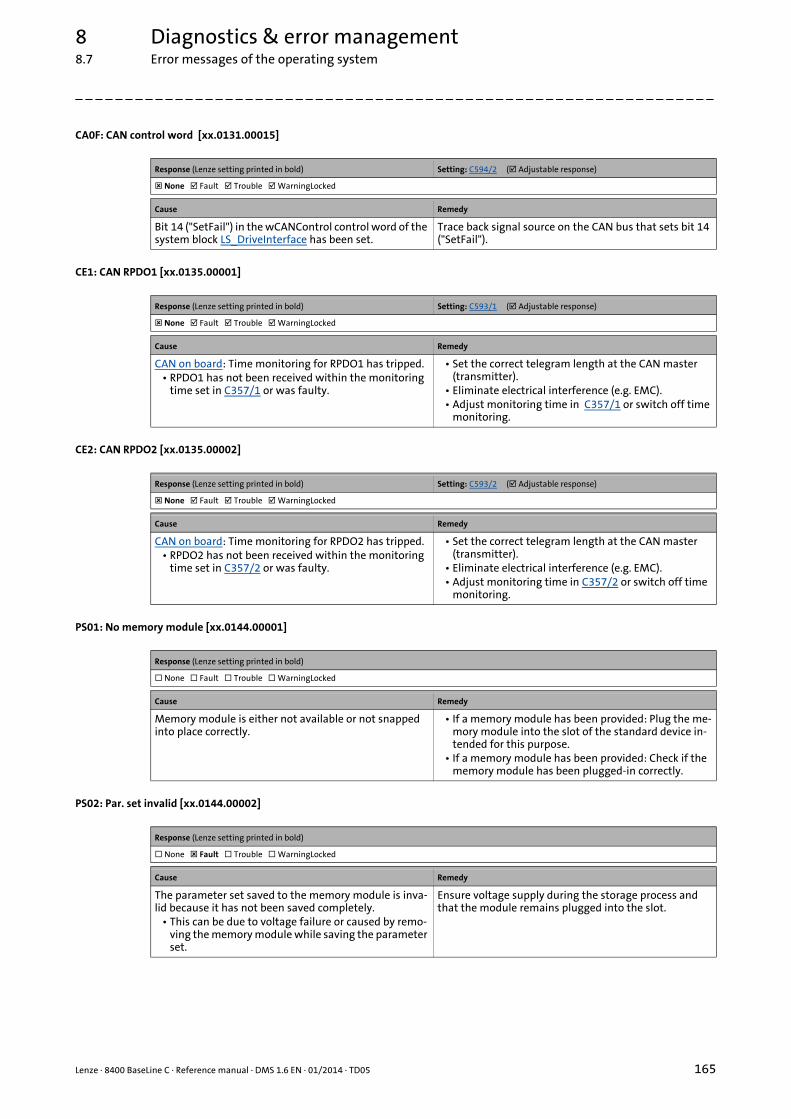
Lenze · 8400 BaseLine C · Reference manual · DMS 1.6 EN · 01/2014 · TD05 165
8 Diagnostics & error management8.7 Error messages of the operating system
_ _ _ _ _ _ _ _ _ _ _ _ _ _ _ _ _ _ _ _ _ _ _ _ _ _ _ _ _ _ _ _ _ _ _ _ _ _ _ _ _ _ _ _ _ _ _ _ _ _ _ _ _ _ _ _ _ _ _ _ _ _ _ _
CA0F: CAN control word [xx.0131.00015]
CE1: CAN RPDO1 [xx.0135.00001]
CE2: CAN RPDO2 [xx.0135.00002]
PS01: No memory module [xx.0144.00001]
PS02: Par. set invalid [xx.0144.00002]
Response (Lenze setting printed in bold) Setting: C594/2 ( Adjustable response)
None Fault Trouble WarningLocked
Cause Remedy
Bit 14 ("SetFail") in the wCANControl control word of the system block LS_DriveInterface has been set.
Trace back signal source on the CAN bus that sets bit 14 ("SetFail").
Response (Lenze setting printed in bold) Setting: C593/1 ( Adjustable response)
None Fault Trouble WarningLocked
Cause Remedy
CAN on board: Time monitoring for RPDO1 has tripped.• RPDO1 has not been received within the monitoring
time set in C357/1 or was faulty.
• Set the correct telegram length at the CAN master (transmitter).
• Eliminate electrical interference (e.g. EMC).• Adjust monitoring time in C357/1 or switch off time
monitoring.
Response (Lenze setting printed in bold) Setting: C593/2 ( Adjustable response)
None Fault Trouble WarningLocked
Cause Remedy
CAN on board: Time monitoring for RPDO2 has tripped.• RPDO2 has not been received within the monitoring
time set in C357/2 or was faulty.
• Set the correct telegram length at the CAN master (transmitter).
• Eliminate electrical interference (e.g. EMC).• Adjust monitoring time in C357/2 or switch off time
monitoring.
Response (Lenze setting printed in bold)
None Fault Trouble WarningLocked
Cause Remedy
Memory module is either not available or not snapped into place correctly.
• If a memory module has been provided: Plug the me-mory module into the slot of the standard device in-tended for this purpose.
• If a memory module has been provided: Check if the memory module has been plugged-in correctly.
Response (Lenze setting printed in bold)
None Fault Trouble WarningLocked
Cause Remedy
The parameter set saved to the memory module is inva-lid because it has not been saved completely.
• This can be due to voltage failure or caused by remo-ving the memory module while saving the parameter set.
Ensure voltage supply during the storage process and that the module remains plugged into the slot.

8 Diagnostics & error management8.7 Error messages of the operating system
166 Lenze · 8400 BaseLine C · Reference manual · DMS 1.6 EN · 01/2014 · TD05
_ _ _ _ _ _ _ _ _ _ _ _ _ _ _ _ _ _ _ _ _ _ _ _ _ _ _ _ _ _ _ _ _ _ _ _ _ _ _ _ _ _ _ _ _ _ _ _ _ _ _ _ _ _ _ _ _ _ _ _ _ _ _ _
PS03: Par. set device invalid [xx.0144.00003]
PS04: Par. set device incompatible [xx.0144.00004]
PS31: Ident. error [xx.0144.00031]
dF01: Internal error 01 [xx.0145.00001]
dF02: Internal error 02 [xx.0145.00002]
Response (Lenze setting printed in bold)
None Fault Trouble WarningLocked
Cause Remedy
The parameter set in the device is invalid. Consultation with Lenze required.
Response (Lenze setting printed in bold)
No Reaction Fault Trouble Warning
Cause Remedy
The parameter set saved to the memory module is in-compatible to the standard device.
• An incompatibility of the parameter set is caused e.g. when the memory module of an 8400 StateLine is plugged into an 8400 BaseLine or the parameter set in the memory module has a higher version than expec-ted by the standard device.
When the memory modules are exchanged, observe the downward compatibility:
• OK: BaseLine V2.0 to BaseLine V3.0• Not OK: StateLine Vx.x to BaseLine Vx.x• Not OK: BaseLine V3.0 to BaseLine < V3.0
Response (Lenze setting printed in bold)
None Fault Trouble WarningLocked
Cause Remedy
Incompatible or unknown HW components have been found.
• Check which HW components are faulty (C203/x: Pro-duct type code).
• Check temperature range of the device at the start.• Check whether a software update at Lenze is possible.
Response (Lenze setting printed in bold)
None Fault Trouble WarningLocked
Cause Remedy
Device error • Reduce switching frequency (C018) to 4 kHz.• If the problem occurs again, you needs to consult Len-
ze.
Response (Lenze setting printed in bold)
None Fault Trouble WarningLocked
Cause Remedy
Device error • Mains switching or restart of the controller, respec-tively.
• If the problem occurs again, you needs to consult Len-ze.
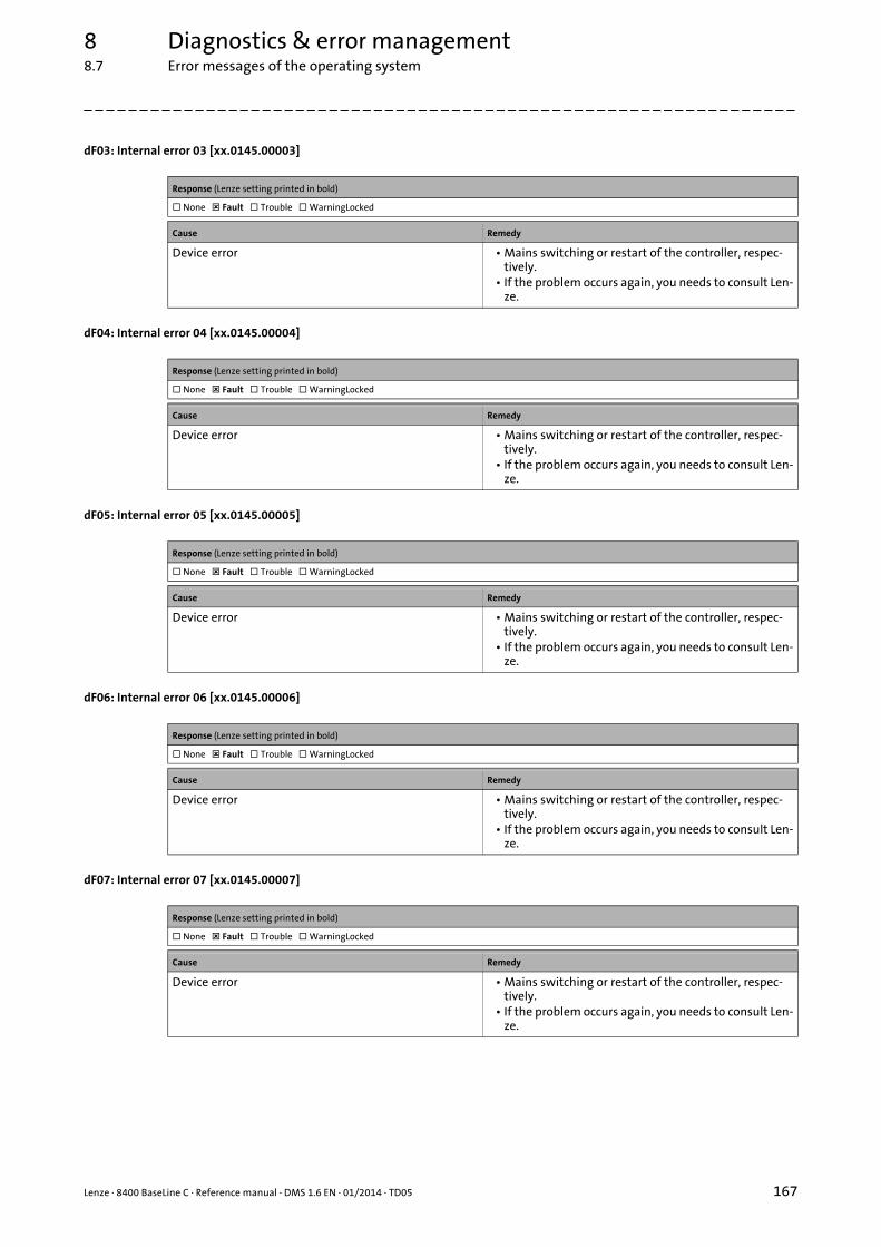
Lenze · 8400 BaseLine C · Reference manual · DMS 1.6 EN · 01/2014 · TD05 167
8 Diagnostics & error management8.7 Error messages of the operating system
_ _ _ _ _ _ _ _ _ _ _ _ _ _ _ _ _ _ _ _ _ _ _ _ _ _ _ _ _ _ _ _ _ _ _ _ _ _ _ _ _ _ _ _ _ _ _ _ _ _ _ _ _ _ _ _ _ _ _ _ _ _ _ _
dF03: Internal error 03 [xx.0145.00003]
dF04: Internal error 04 [xx.0145.00004]
dF05: Internal error 05 [xx.0145.00005]
dF06: Internal error 06 [xx.0145.00006]
dF07: Internal error 07 [xx.0145.00007]
Response (Lenze setting printed in bold)
None Fault Trouble WarningLocked
Cause Remedy
Device error • Mains switching or restart of the controller, respec-tively.
• If the problem occurs again, you needs to consult Len-ze.
Response (Lenze setting printed in bold)
None Fault Trouble WarningLocked
Cause Remedy
Device error • Mains switching or restart of the controller, respec-tively.
• If the problem occurs again, you needs to consult Len-ze.
Response (Lenze setting printed in bold)
None Fault Trouble WarningLocked
Cause Remedy
Device error • Mains switching or restart of the controller, respec-tively.
• If the problem occurs again, you needs to consult Len-ze.
Response (Lenze setting printed in bold)
None Fault Trouble WarningLocked
Cause Remedy
Device error • Mains switching or restart of the controller, respec-tively.
• If the problem occurs again, you needs to consult Len-ze.
Response (Lenze setting printed in bold)
None Fault Trouble WarningLocked
Cause Remedy
Device error • Mains switching or restart of the controller, respec-tively.
• If the problem occurs again, you needs to consult Len-ze.
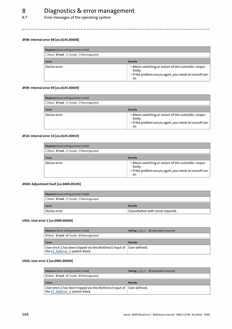
8 Diagnostics & error management8.7 Error messages of the operating system
168 Lenze · 8400 BaseLine C · Reference manual · DMS 1.6 EN · 01/2014 · TD05
_ _ _ _ _ _ _ _ _ _ _ _ _ _ _ _ _ _ _ _ _ _ _ _ _ _ _ _ _ _ _ _ _ _ _ _ _ _ _ _ _ _ _ _ _ _ _ _ _ _ _ _ _ _ _ _ _ _ _ _ _ _ _ _
dF08: Internal error 08 [xx.0145.00008]
dF09: Internal error 09 [xx.0145.00009]
dF10: Internal error 10 [xx.0145.00010]
dH69: Adjustment fault [xx.0400.00105]
US01: User error 1 [xx.0980.00000]
US02: User error 2 [xx.0981.00000]
Response (Lenze setting printed in bold)
None Fault Trouble WarningLocked
Cause Remedy
Device error • Mains switching or restart of the controller, respec-tively.
• If the problem occurs again, you needs to consult Len-ze.
Response (Lenze setting printed in bold)
None Fault Trouble WarningLocked
Cause Remedy
Device error • Mains switching or restart of the controller, respec-tively.
• If the problem occurs again, you needs to consult Len-ze.
Response (Lenze setting printed in bold)
None Fault Trouble WarningLocked
Cause Remedy
Device error • Mains switching or restart of the controller, respec-tively.
• If the problem occurs again, you needs to consult Len-ze.
Response (Lenze setting printed in bold)
None Fault Trouble WarningLocked
Cause Remedy
Device error Consultation with Lenze required.
Response (Lenze setting printed in bold) Setting: C581/1 ( Adjustable response)
None Fault Trouble WarningLocked
Cause Remedy
User error 1 has been tripped via the bSetError1 input of the LS_SetError_1 system block.
User-defined.
Response (Lenze setting printed in bold) Setting: C581/2 ( Adjustable response)
None Fault Trouble WarningLocked
Cause Remedy
User error 2 has been tripped via the bSetError2 input of the LS_SetError_1 system block.
User-defined.

Lenze · 8400 BaseLine C · Reference manual · DMS 1.6 EN · 01/2014 · TD05 169
9 System bus "CAN on board"
_ _ _ _ _ _ _ _ _ _ _ _ _ _ _ _ _ _ _ _ _ _ _ _ _ _ _ _ _ _ _ _ _ _ _ _ _ _ _ _ _ _ _ _ _ _ _ _ _ _ _ _ _ _ _ _ _ _ _ _ _ _ _ _
9 System bus "CAN on board"
The controller has an integrated CANopen system bus interface ("CAN on board") which is used toexchange i.a. process data and parameter values between the nodes. Furthermore, other modulescan be connected via this interface such as decentralised terminals, operator and input devices(HMIs), as well as external controls and host systems.
The interface transfers CAN objects following the CANopen communication profile (CiA DS301, ver-sion 4.02) developed by the umbrella organisation of CiA (CAN in Automation) in conformity withthe CAL (CAN Application Layer).
Tip!• In the »Engineer« parameter list, category CAN, you can find the parameters relevant for
the CANopen system bus interface classified in different subcategories.• Information on CAN communication modules and CANopen system bus interfaces of
other Lenze devices is provided in the "CAN" communication manual in the Lenze library.
The preconfigured interconnection of the internal interfaces for a control via CAN is shown in chapter "Drive application" in figure [7-2]. ( 136)

9 System bus "CAN on board"9.1 General information
170 Lenze · 8400 BaseLine C · Reference manual · DMS 1.6 EN · 01/2014 · TD05
_ _ _ _ _ _ _ _ _ _ _ _ _ _ _ _ _ _ _ _ _ _ _ _ _ _ _ _ _ _ _ _ _ _ _ _ _ _ _ _ _ _ _ _ _ _ _ _ _ _ _ _ _ _ _ _ _ _ _ _ _ _ _ _
9.1 General information
For many years, the system bus (CAN) based on the CANopen communication profile has been inte-grated in Lenze controllers. Due to the lower number of data objects available, the functionality andcompatibility of the previous system bus are lower as compared to CANopen. For parameter setting,two parameter data channels are always available to the user while CANopen provides only one ac-tive parameter channel.
The system bus (CANopen) of the Inverter Drives 8400 is a further development of the system bus(CAN) including the following properties:
• Full compatibility according to CANopen DS301, V4.02.
• Support of the "Heartbeat" NMT slave function (DS301, V4.02).
• Number of parameterisable server SDO channels:• Max. 2 channels with 1 ... 8 bytes• Due to the 2 server SDO channels, an address range of 1 ... 63 is provided.
• Number of parameterisable PDO channels:• For device version "BaseLine C":
max. 2 Transmit-PDOs (TPDOs) with 1 ... 8 bytes (adjustable)max. 2 Receive-PDOs (RPDOs) with 1 ... 8 bytes (adjustable)
• From device version "StateLine" onwards:max. 3 Transmit-PDOs (TPDOs) with 1 ... 8 bytes (adjustable)max. 3 Receive-PDOs (RPDOs) with 1 ... 8 bytes (adjustable)
• All PDO channels are functionally equivalent.
• Monitoring of the RPDOs for data reception
• Adjustable error response to ...• physical CAN errors (frame, bit, ACK error)• bus-stop, bus working• absent PDOs
• Telegram counters for SDOs and PDOs
• Bus status diagnostics
• Boot-up telegram generation
• Emergency telegram generation
• Reset node telegram generation (in case of master configuration)
• Sync telegram generation and response to sync telegrams:• Data transmission/reception• Device-internal time base synchronisation
• Abort codes
• All CAN on board functions can be parameterised via codes
• Object directory (all mandatory functions, optional functions, indexes)
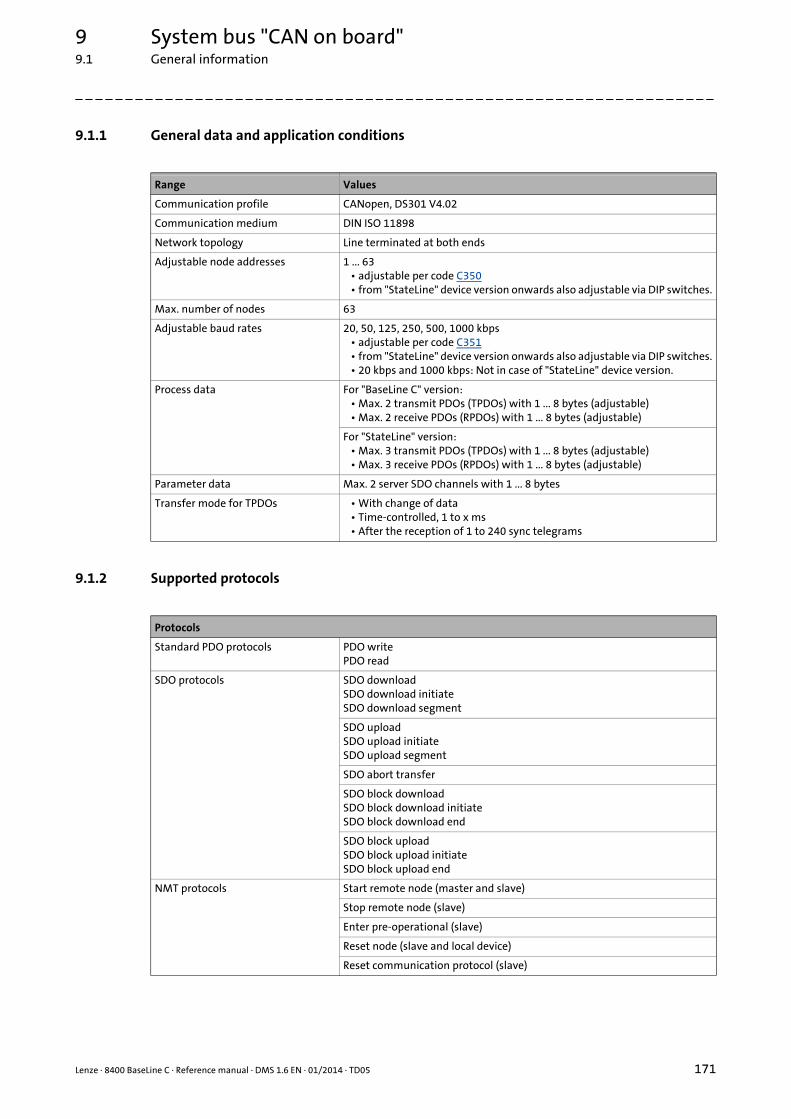
Lenze · 8400 BaseLine C · Reference manual · DMS 1.6 EN · 01/2014 · TD05 171
9 System bus "CAN on board"9.1 General information
_ _ _ _ _ _ _ _ _ _ _ _ _ _ _ _ _ _ _ _ _ _ _ _ _ _ _ _ _ _ _ _ _ _ _ _ _ _ _ _ _ _ _ _ _ _ _ _ _ _ _ _ _ _ _ _ _ _ _ _ _ _ _ _
9.1.1 General data and application conditions
9.1.2 Supported protocols
Range Values
Communication profile CANopen, DS301 V4.02
Communication medium DIN ISO 11898
Network topology Line terminated at both ends
Adjustable node addresses 1 ... 63• adjustable per code C350• from "StateLine" device version onwards also adjustable via DIP switches.
Max. number of nodes 63
Adjustable baud rates 20, 50, 125, 250, 500, 1000 kbps• adjustable per code C351• from "StateLine" device version onwards also adjustable via DIP switches.• 20 kbps and 1000 kbps: Not in case of "StateLine" device version.
Process data For "BaseLine C" version:• Max. 2 transmit PDOs (TPDOs) with 1 ... 8 bytes (adjustable)• Max. 2 receive PDOs (RPDOs) with 1 ... 8 bytes (adjustable)
For "StateLine" version:• Max. 3 transmit PDOs (TPDOs) with 1 ... 8 bytes (adjustable)• Max. 3 receive PDOs (RPDOs) with 1 ... 8 bytes (adjustable)
Parameter data Max. 2 server SDO channels with 1 ... 8 bytes
Transfer mode for TPDOs • With change of data• Time-controlled, 1 to x ms• After the reception of 1 to 240 sync telegrams
Protocols
Standard PDO protocols PDO writePDO read
SDO protocols SDO downloadSDO download initiateSDO download segment
SDO uploadSDO upload initiateSDO upload segment
SDO abort transfer
SDO block downloadSDO block download initiateSDO block download end
SDO block uploadSDO block upload initiateSDO block upload end
NMT protocols Start remote node (master and slave)
Stop remote node (slave)
Enter pre-operational (slave)
Reset node (slave and local device)
Reset communication protocol (slave)
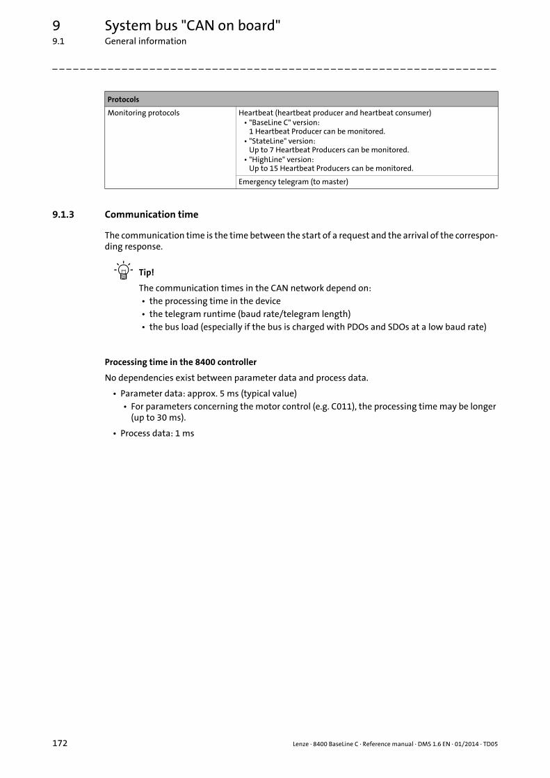
9 System bus "CAN on board"9.1 General information
172 Lenze · 8400 BaseLine C · Reference manual · DMS 1.6 EN · 01/2014 · TD05
_ _ _ _ _ _ _ _ _ _ _ _ _ _ _ _ _ _ _ _ _ _ _ _ _ _ _ _ _ _ _ _ _ _ _ _ _ _ _ _ _ _ _ _ _ _ _ _ _ _ _ _ _ _ _ _ _ _ _ _ _ _ _ _
9.1.3 Communication time
The communication time is the time between the start of a request and the arrival of the correspon-ding response.
Tip!
The communication times in the CAN network depend on:• the processing time in the device• the telegram runtime (baud rate/telegram length)• the bus load (especially if the bus is charged with PDOs and SDOs at a low baud rate)
Processing time in the 8400 controller
No dependencies exist between parameter data and process data.
• Parameter data: approx. 5 ms (typical value)• For parameters concerning the motor control (e.g. C011), the processing time may be longer
(up to 30 ms).
• Process data: 1 ms
Monitoring protocols Heartbeat (heartbeat producer and heartbeat consumer)• "BaseLine C" version:
1 Heartbeat Producer can be monitored.• "StateLine" version:
Up to 7 Heartbeat Producers can be monitored.• "HighLine" version:
Up to 15 Heartbeat Producers can be monitored.
Emergency telegram (to master)
Protocols
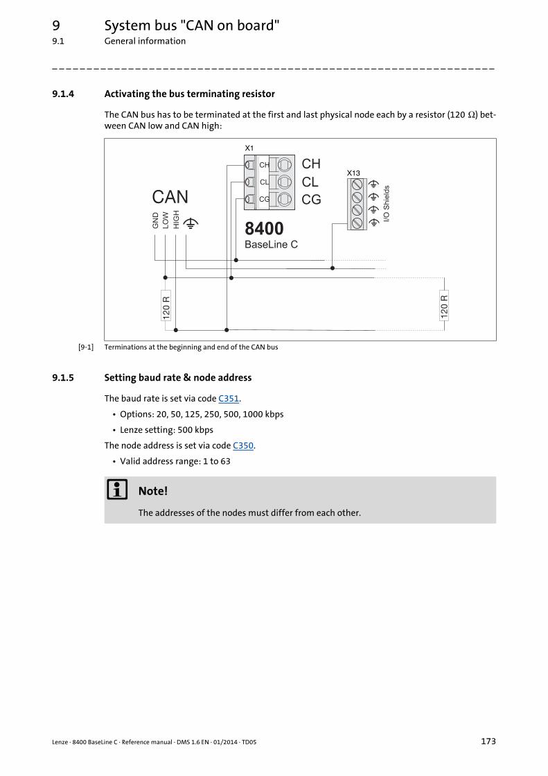
Lenze · 8400 BaseLine C · Reference manual · DMS 1.6 EN · 01/2014 · TD05 173
9 System bus "CAN on board"9.1 General information
_ _ _ _ _ _ _ _ _ _ _ _ _ _ _ _ _ _ _ _ _ _ _ _ _ _ _ _ _ _ _ _ _ _ _ _ _ _ _ _ _ _ _ _ _ _ _ _ _ _ _ _ _ _ _ _ _ _ _ _ _ _ _ _
9.1.4 Activating the bus terminating resistor
The CAN bus has to be terminated at the first and last physical node each by a resistor (120 Ω) bet-ween CAN low and CAN high:
[9-1] Terminations at the beginning and end of the CAN bus
9.1.5 Setting baud rate & node address
The baud rate is set via code C351.
• Options: 20, 50, 125, 250, 500, 1000 kbps
• Lenze setting: 500 kbps
The node address is set via code C350.
• Valid address range: 1 to 63
8400BaseLine C
CH
CL
CG
120
R
CAN
120
R
LO
W
GN
D
I/O
Shie
lds
CH
CL
CG
X1
HIG
HX13
Note!
The addresses of the nodes must differ from each other.
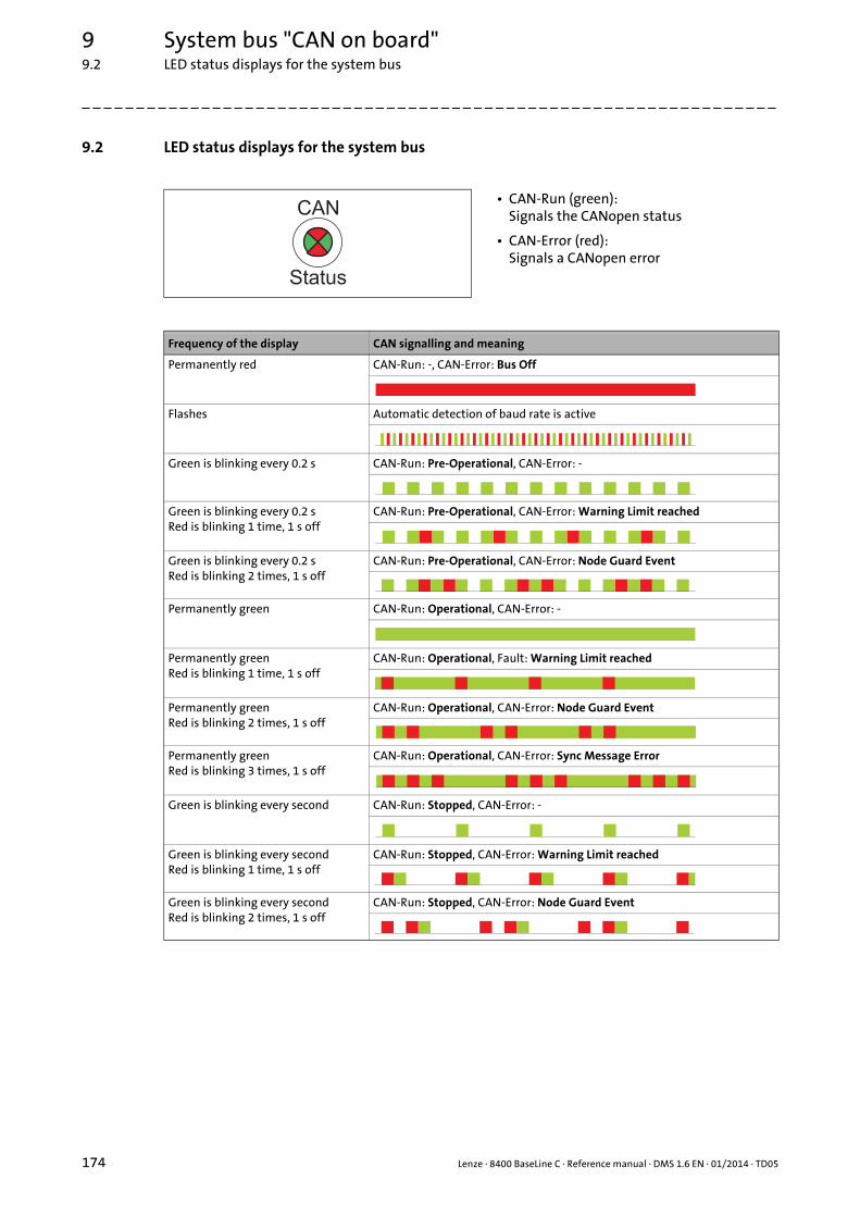
9 System bus "CAN on board"9.2 LED status displays for the system bus
174 Lenze · 8400 BaseLine C · Reference manual · DMS 1.6 EN · 01/2014 · TD05
_ _ _ _ _ _ _ _ _ _ _ _ _ _ _ _ _ _ _ _ _ _ _ _ _ _ _ _ _ _ _ _ _ _ _ _ _ _ _ _ _ _ _ _ _ _ _ _ _ _ _ _ _ _ _ _ _ _ _ _ _ _ _ _
9.2 LED status displays for the system bus
• CAN-Run (green): Signals the CANopen status
• CAN-Error (red): Signals a CANopen error
Frequency of the display CAN signalling and meaning
Permanently red CAN-Run: -, CAN-Error: Bus Off
Flashes Automatic detection of baud rate is active
Green is blinking every 0.2 s CAN-Run: Pre-Operational, CAN-Error: -
Green is blinking every 0.2 sRed is blinking 1 time, 1 s off
CAN-Run: Pre-Operational, CAN-Error: Warning Limit reached
Green is blinking every 0.2 sRed is blinking 2 times, 1 s off
CAN-Run: Pre-Operational, CAN-Error: Node Guard Event
Permanently green CAN-Run: Operational, CAN-Error: -
Permanently greenRed is blinking 1 time, 1 s off
CAN-Run: Operational, Fault: Warning Limit reached
Permanently greenRed is blinking 2 times, 1 s off
CAN-Run: Operational, CAN-Error: Node Guard Event
Permanently greenRed is blinking 3 times, 1 s off
CAN-Run: Operational, CAN-Error: Sync Message Error
Green is blinking every second CAN-Run: Stopped, CAN-Error: -
Green is blinking every secondRed is blinking 1 time, 1 s off
CAN-Run: Stopped, CAN-Error: Warning Limit reached
Green is blinking every secondRed is blinking 2 times, 1 s off
CAN-Run: Stopped, CAN-Error: Node Guard Event
CAN
Status

Lenze · 8400 BaseLine C · Reference manual · DMS 1.6 EN · 01/2014 · TD05 175
9 System bus "CAN on board"9.3 Going online via system bus (CAN on board)
_ _ _ _ _ _ _ _ _ _ _ _ _ _ _ _ _ _ _ _ _ _ _ _ _ _ _ _ _ _ _ _ _ _ _ _ _ _ _ _ _ _ _ _ _ _ _ _ _ _ _ _ _ _ _ _ _ _ _ _ _ _ _ _
9.3 Going online via system bus (CAN on board)
The integrated system bus interface (CAN on board, X1 terminal) can also be used for the commu-nication between the »Engineer« and the controller, alternatively to the USB diagnostic adapter.
• Lenze offers the following communication accessories for connection to the PC:
Communication accessories PC interface
PC system bus adapter 2173incl. connection cable and voltage supply adapter
• for DIN keyboard connection (EMF2173IB)• for PS/2 keyboard connection (EMF2173IBV002)• for PS/2 keyboard connection with electrical isolation (EMF2173IBV003)
Parallel interface(LPT port)
PC system bus adapter 2177incl. connection cable (EMF2177IB)
USB(Universal Serial Bus)
Note!
• For detailed information about the PC system bus adapter, please see the "CAN Com-munication Manual".
• Please observe the documentation for the PC system bus adapter!• In the »Engineer«, go to the Device assignment offline devices dialog box and select the
"System bus CAN" entry from the Bus connection list field to establish an online con-nection.

9 System bus "CAN on board"9.4 Structure of the CAN data telegram
176 Lenze · 8400 BaseLine C · Reference manual · DMS 1.6 EN · 01/2014 · TD05
_ _ _ _ _ _ _ _ _ _ _ _ _ _ _ _ _ _ _ _ _ _ _ _ _ _ _ _ _ _ _ _ _ _ _ _ _ _ _ _ _ _ _ _ _ _ _ _ _ _ _ _ _ _ _ _ _ _ _ _ _ _ _ _
9.4 Structure of the CAN data telegram
[9-2] Basic structure of the CAN telegram
The following subchapters provide a detailed description of the identifier and the user data. Theother signals refer to the transfer characteristics of the CAN telegram whose description is not in-cluded in the scope of this documentation.
Tip!
Please visit the homepage of the CAN user organisation CiA (CAN in automation) for further information:http://www.can-cia.org
9.4.1 Identifier
The principle of the CAN communication is based on a message-oriented data exchange between atransmitter and many receivers. All nodes can transmit and receive quasi-simultaneously.
The identifier, also called COB-ID (abbr. for communication object identifier), is used to controlwhich node is to receive a transmitted message. In addition to the addressing, the identifier con-tains information on the priority of the message and the type of user data.
The identifier consists of a basic identifier and the node address of the node to be addressed:
Identifier (COB-ID) = basic identifier + node address (node ID)
Exception: The identifier for process data/heartbeat/emergency objects as well as network ma-nagement and sync telegrams is freely assigned by the user (either manually or automatically by thenetwork configurator), or is permanently assigned.
Node address (node ID)
Every node of the system bus network must be assigned to a node address (also called node ID)within the valid address range (1 ... 63) for unambiguous identification.
• Assigning a node address more than once within a network is impermissible.
• The own node address is configured via code C350.
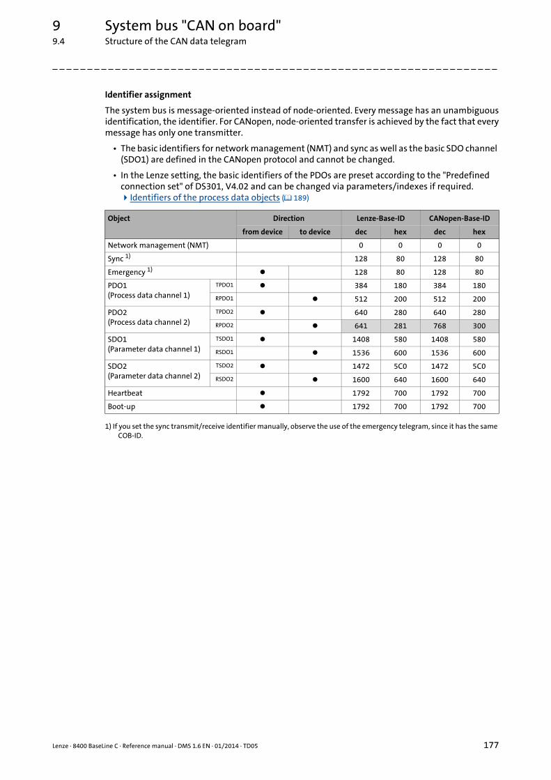
Lenze · 8400 BaseLine C · Reference manual · DMS 1.6 EN · 01/2014 · TD05 177
9 System bus "CAN on board"9.4 Structure of the CAN data telegram
_ _ _ _ _ _ _ _ _ _ _ _ _ _ _ _ _ _ _ _ _ _ _ _ _ _ _ _ _ _ _ _ _ _ _ _ _ _ _ _ _ _ _ _ _ _ _ _ _ _ _ _ _ _ _ _ _ _ _ _ _ _ _ _
Identifier assignment
The system bus is message-oriented instead of node-oriented. Every message has an unambiguousidentification, the identifier. For CANopen, node-oriented transfer is achieved by the fact that everymessage has only one transmitter.
• The basic identifiers for network management (NMT) and sync as well as the basic SDO channel (SDO1) are defined in the CANopen protocol and cannot be changed.
• In the Lenze setting, the basic identifiers of the PDOs are preset according to the "Predefined connection set" of DS301, V4.02 and can be changed via parameters/indexes if required. Identifiers of the process data objects ( 189)
1) If you set the sync transmit/receive identifier manually, observe the use of the emergency telegram, since it has the same COB-ID.
Object Direction Lenze-Base-ID CANopen-Base-ID
from device to device dec hex dec hex
Network management (NMT) 0 0 0 0
Sync 1) 128 80 128 80
Emergency 1) 128 80 128 80
PDO1 (Process data channel 1)
TPDO1 384 180 384 180
RPDO1 512 200 512 200
PDO2 (Process data channel 2)
TPDO2 640 280 640 280
RPDO2 641 281 768 300
SDO1 (Parameter data channel 1)
TSDO1 1408 580 1408 580
RSDO1 1536 600 1536 600
SDO2(Parameter data channel 2)
TSDO2 1472 5C0 1472 5C0
RSDO2 1600 640 1600 640
Heartbeat 1792 700 1792 700
Boot-up 1792 700 1792 700
9 System bus "CAN on board"9.4 Structure of the CAN data telegram
178 Lenze · 8400 BaseLine C · Reference manual · DMS 1.6 EN · 01/2014 · TD05
_ _ _ _ _ _ _ _ _ _ _ _ _ _ _ _ _ _ _ _ _ _ _ _ _ _ _ _ _ _ _ _ _ _ _ _ _ _ _ _ _ _ _ _ _ _ _ _ _ _ _ _ _ _ _ _ _ _ _ _ _ _ _ _
9.4.2 User data
All nodes communicate by exchanging data telegrams via the system bus. The user data area of theCAN telegram either contains network management data or parameter data or process data:
Networkmanagement data
(NMT data)
• Control information on start, stop, reset, etc. of communication to specific nodes or to all nodes of the CAN network.
Process data
(PDOs – process data objects)
• Process data are transferred via the process data channel.
• Process data can be used to control the controller.
• Process data are not saved to the controller.
• Process data are transmitted between host system and nodes to ensure continuous exchange of current input and output data.
• Process data usually are unscaled/scalable raw data.
• Process data are, for instance, setpoints and actual values.
• The exact meaning of the PDO file contents is determined via the function block editor (FB Edi-tor) in the I/O level or via the PDO mapping.
Parameter data
(SDOs – service data objects)
• Parameter data are the CANopen indexes or, in case of Lenze devices, the codes.
• Parameters are, for instance, used for one-off plant setting during commissioning or when the material is changed on a production machine.
• Parameter data are transmitted as SDOs via the parameter data channel. They are acknow-ledged by the receiver, i.e. the transmitter gets a feedback about the transmission being suc-cessful or not.
• The parameter data channel enables access to all Lenze codes and CANopen indexes.
• Parameter changes are automatically saved to the controller until mains switching.
• In general, the parameter transfer is not time-critical.
• Parameter data are, for instance, operating parameters, diagnostic information and motor data as well as control information on the interconnection of function blocks in the I/O level of the FB Editor.
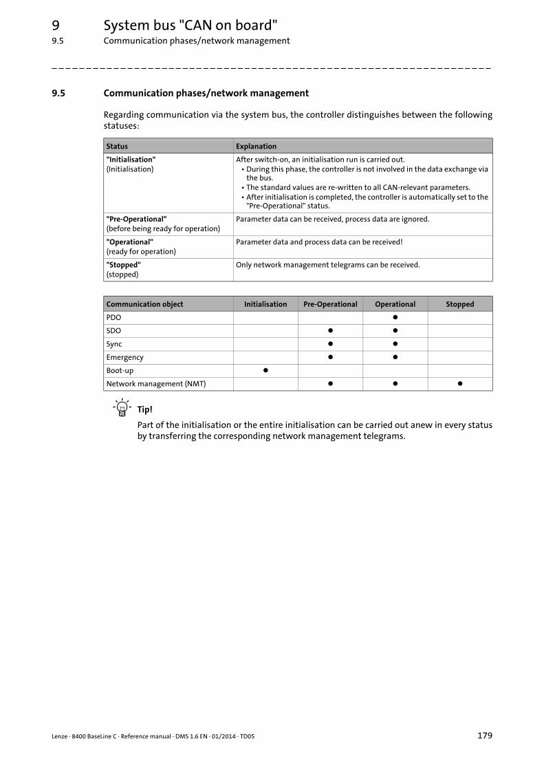
Lenze · 8400 BaseLine C · Reference manual · DMS 1.6 EN · 01/2014 · TD05 179
9 System bus "CAN on board"9.5 Communication phases/network management
_ _ _ _ _ _ _ _ _ _ _ _ _ _ _ _ _ _ _ _ _ _ _ _ _ _ _ _ _ _ _ _ _ _ _ _ _ _ _ _ _ _ _ _ _ _ _ _ _ _ _ _ _ _ _ _ _ _ _ _ _ _ _ _
9.5 Communication phases/network management
Regarding communication via the system bus, the controller distinguishes between the followingstatuses:
Tip!
Part of the initialisation or the entire initialisation can be carried out anew in every statusby transferring the corresponding network management telegrams.
Status Explanation
"Initialisation"(Initialisation)
After switch-on, an initialisation run is carried out.• During this phase, the controller is not involved in the data exchange via
the bus.• The standard values are re-written to all CAN-relevant parameters.• After initialisation is completed, the controller is automatically set to the
"Pre-Operational" status.
"Pre-Operational"(before being ready for operation)
Parameter data can be received, process data are ignored.
"Operational"(ready for operation)
Parameter data and process data can be received!
"Stopped"(stopped)
Only network management telegrams can be received.
Communication object Initialisation Pre-Operational Operational Stopped
PDO
SDO
Sync
Emergency
Boot-up
Network management (NMT)
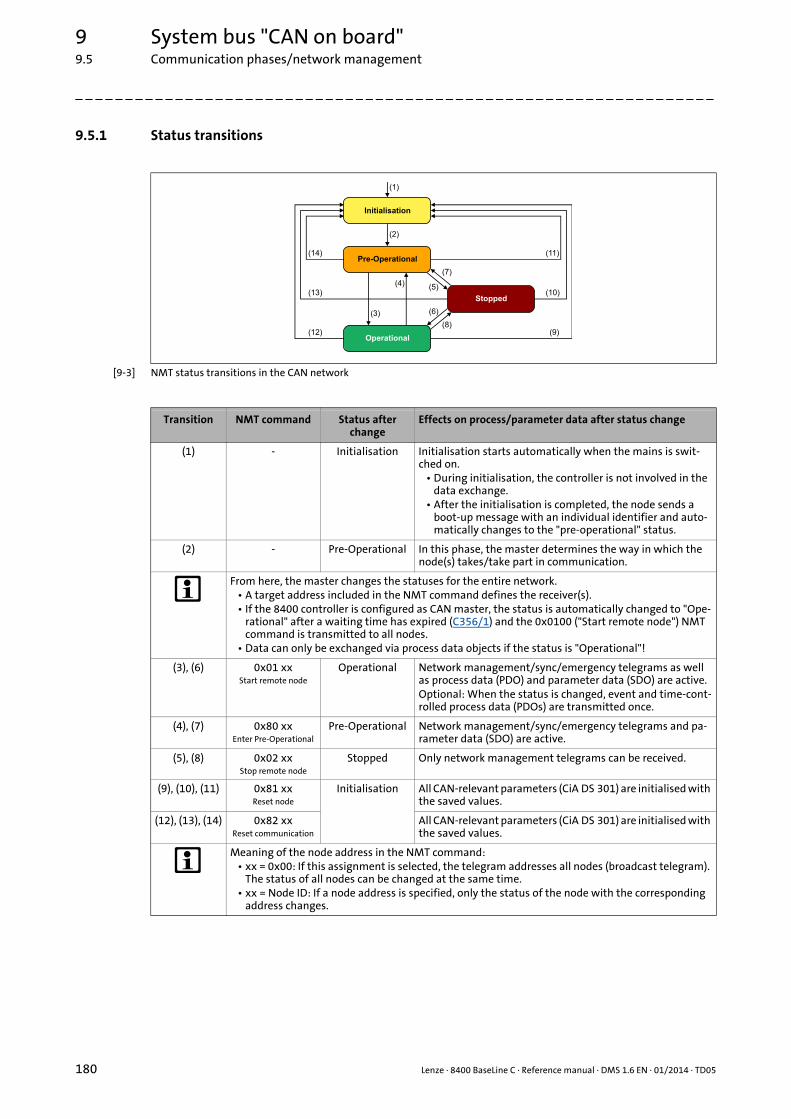
9 System bus "CAN on board"9.5 Communication phases/network management
180 Lenze · 8400 BaseLine C · Reference manual · DMS 1.6 EN · 01/2014 · TD05
_ _ _ _ _ _ _ _ _ _ _ _ _ _ _ _ _ _ _ _ _ _ _ _ _ _ _ _ _ _ _ _ _ _ _ _ _ _ _ _ _ _ _ _ _ _ _ _ _ _ _ _ _ _ _ _ _ _ _ _ _ _ _ _
9.5.1 Status transitions
[9-3] NMT status transitions in the CAN network
Transition NMT command Status after change
Effects on process/parameter data after status change
(1) - Initialisation Initialisation starts automatically when the mains is swit-ched on.
• During initialisation, the controller is not involved in the data exchange.
• After the initialisation is completed, the node sends a boot-up message with an individual identifier and auto-matically changes to the "pre-operational" status.
(2) - Pre-Operational In this phase, the master determines the way in which the node(s) takes/take part in communication.
From here, the master changes the statuses for the entire network.• A target address included in the NMT command defines the receiver(s).• If the 8400 controller is configured as CAN master, the status is automatically changed to "Ope-
rational" after a waiting time has expired (C356/1) and the 0x0100 ("Start remote node") NMT command is transmitted to all nodes.
• Data can only be exchanged via process data objects if the status is "Operational"!
(3), (6) 0x01 xxStart remote node
Operational Network management/sync/emergency telegrams as well as process data (PDO) and parameter data (SDO) are active.Optional: When the status is changed, event and time-cont-rolled process data (PDOs) are transmitted once.
(4), (7) 0x80 xxEnter Pre-Operational
Pre-Operational Network management/sync/emergency telegrams and pa-rameter data (SDO) are active.
(5), (8) 0x02 xxStop remote node
Stopped Only network management telegrams can be received.
(9), (10), (11) 0x81 xxReset node
Initialisation All CAN-relevant parameters (CiA DS 301) are initialised with the saved values.
(12), (13), (14) 0x82 xxReset communication
All CAN-relevant parameters (CiA DS 301) are initialised with the saved values.
Meaning of the node address in the NMT command:• xx = 0x00: If this assignment is selected, the telegram addresses all nodes (broadcast telegram).
The status of all nodes can be changed at the same time.• xx = Node ID: If a node address is specified, only the status of the node with the corresponding
address changes.

Lenze · 8400 BaseLine C · Reference manual · DMS 1.6 EN · 01/2014 · TD05 181
9 System bus "CAN on board"9.5 Communication phases/network management
_ _ _ _ _ _ _ _ _ _ _ _ _ _ _ _ _ _ _ _ _ _ _ _ _ _ _ _ _ _ _ _ _ _ _ _ _ _ _ _ _ _ _ _ _ _ _ _ _ _ _ _ _ _ _ _ _ _ _ _ _ _ _ _
9.5.2 Network management telegram (NMT)
The telegram for the network management contains identifier "0" and the command included inthe user data which consists of the command byte and the node address:
[9-4] Network management telegram for changing over the communication phases
The change-over of the communication phases for the entire network is carried out by one node, theCAN master. The function of the CAN master can also be carried out by the controller.Parameterising the controller as CAN master ( 182)
Example:
Data can only be exchanged via process data objects if the status is "Operational".If the CAN masteris supposed to switch all nodes connected to the bus from the "Pre-Operational" communicationstatus to the "Operational" communication status, the identifier and user data in the transmissiontelegram must be set as follows:
• Identifier: 0x00 (network management)
• User data: 0x0100 ("Start remote node" NMT command to all nodes)
Command specifier (cs) NMT command
dec hex
1 0x01 Start remote node
2 0x02 Stop remote node
128 0x80 Enter Pre-Operational
129 0x81 Reset node
130 0x82 Reset communication

9 System bus "CAN on board"9.5 Communication phases/network management
182 Lenze · 8400 BaseLine C · Reference manual · DMS 1.6 EN · 01/2014 · TD05
_ _ _ _ _ _ _ _ _ _ _ _ _ _ _ _ _ _ _ _ _ _ _ _ _ _ _ _ _ _ _ _ _ _ _ _ _ _ _ _ _ _ _ _ _ _ _ _ _ _ _ _ _ _ _ _ _ _ _ _ _ _ _ _
9.5.3 Parameterising the controller as CAN master
If the initialisation of the system bus and the associated status change from "Pre-Operational" to"Operational" is not effected by a superimposed host system, the controller can instead be definedto be a "quasi" master to execute this task.
The controller is configured as CAN master in C352.
• Being the CAN master, the controller sets all nodes connected to the bus (broadcast telegram) to the "Operational" communication status with the "Start remote node" NMT telegram. Only in this communication status, data can be exchanged via process data objects.
• A delay time can be set in C356/1 which must expire after mains switching before the controller transmits the "Start remote node" NMT telegram.
Tip!
Master functionality is only required during the initialisation phase of the drive system.
Parameter Info Lenze setting
Value Unit
C352 CAN slave/master Slave
C356/1 CAN delay boot-up - Operational 3000 ms
Note!
A change in master/slave operation in C352 will only become effective by• renewed mains switching of the controller
or• the "Reset node" or "Reset communication" NMT telegram has been transmitted to
the controller.
The "CAN reset node" device command (C002/26) is provided as an alternative to the "Reset node" NMT telegram for the reinitialisation of the CAN-specific device parame-ters.
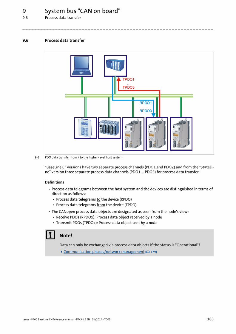
Lenze · 8400 BaseLine C · Reference manual · DMS 1.6 EN · 01/2014 · TD05 183
9 System bus "CAN on board"9.6 Process data transfer
_ _ _ _ _ _ _ _ _ _ _ _ _ _ _ _ _ _ _ _ _ _ _ _ _ _ _ _ _ _ _ _ _ _ _ _ _ _ _ _ _ _ _ _ _ _ _ _ _ _ _ _ _ _ _ _ _ _ _ _ _ _ _ _
9.6 Process data transfer
[9-5] PDO data transfer from / to the higher-level host system
"BaseLine C" versions have two separate process channels (PDO1 and PDO2) and from the "StateLi-ne" version three separate process data channels (PDO1 ... PDO3) for process data transfer.
Definitions
• Process data telegrams between the host system and the devices are distinguished in terms of direction as follows:• Process data telegrams to the device (RPDO)• Process data telegrams from the device (TPDO)
• The CANopen process data objects are designated as seen from the node's view:• Receive PDOs (RPDOx): Process data object received by a node• Transmit PDOs (TPDOx): Process data object sent by a node
Note!
Data can only be exchanged via process data objects if the status is "Operational"!
Communication phases/network management ( 179)
9 System bus "CAN on board"9.6 Process data transfer
184 Lenze · 8400 BaseLine C · Reference manual · DMS 1.6 EN · 01/2014 · TD05
_ _ _ _ _ _ _ _ _ _ _ _ _ _ _ _ _ _ _ _ _ _ _ _ _ _ _ _ _ _ _ _ _ _ _ _ _ _ _ _ _ _ _ _ _ _ _ _ _ _ _ _ _ _ _ _ _ _ _ _ _ _ _ _
9.6.1 Available process data objects
8400 BaseLine C controllers have a maximum number of 2 receive PDOs (RPDOs) and 2 transmitPDOs (TPDOs).
Receive PDOs (RPDOs)
The process data objects transmitted from the CAN bus to the drive are processed via the LP_CanIn1and LP_CanIn2 port blocks.
• Every port block provides 4 words (2 bytes/word). The data of every first word are provided in a bit decoded manner (bit 0 ... 15).
• The first word of the LP_CanIn1 port block is defined as control word.• For the predefined assignment, see the "Process data assignment for control via CAN" sub-
chapter for drive application.
Transmit PDOs (TPDOs)
The process data objects transmitted from the drive to the CAN bus are processed via theLP_CanOut1 and LP_CanOut2 port blocks.
• Every port block receives 4 words (2 bytes/word). The data of every first word are transmitted bit by bit (bit 0 ... 15).
• The first word of the LP_CanOut1 port block is defined as status word.• For the predefined assignment, see the "Process data assignment for control via CAN" sub-
chapter for drive application.
The preconfigured interconnection of the internal interfaces for a control via CAN is shown in chapter "Drive application" in figure [7-2]. ( 136)
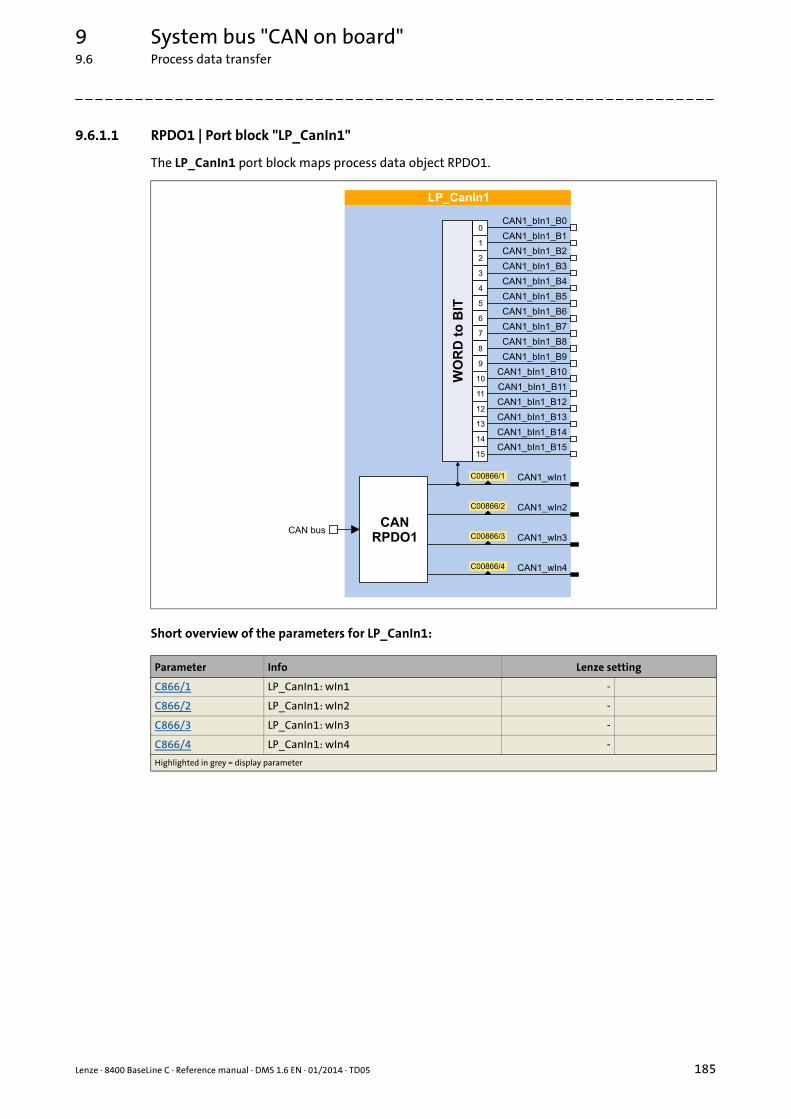
Lenze · 8400 BaseLine C · Reference manual · DMS 1.6 EN · 01/2014 · TD05 185
9 System bus "CAN on board"9.6 Process data transfer
_ _ _ _ _ _ _ _ _ _ _ _ _ _ _ _ _ _ _ _ _ _ _ _ _ _ _ _ _ _ _ _ _ _ _ _ _ _ _ _ _ _ _ _ _ _ _ _ _ _ _ _ _ _ _ _ _ _ _ _ _ _ _ _
9.6.1.1 RPDO1 | Port block "LP_CanIn1"
The LP_CanIn1 port block maps process data object RPDO1.
Short overview of the parameters for LP_CanIn1:
Parameter Info Lenze setting
C866/1 LP_CanIn1: wIn1 -
C866/2 LP_CanIn1: wIn2 -
C866/3 LP_CanIn1: wIn3 -
C866/4 LP_CanIn1: wIn4 -
Highlighted in grey = display parameter
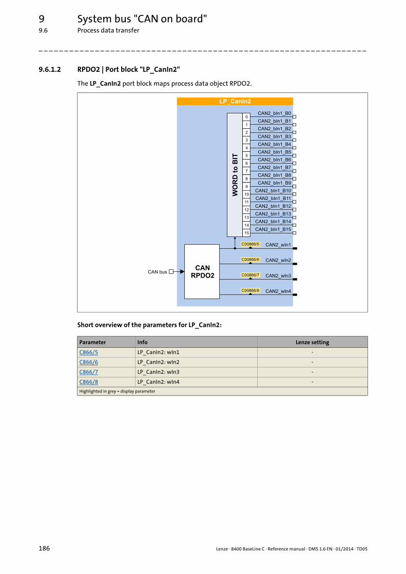
9 System bus "CAN on board"9.6 Process data transfer
186 Lenze · 8400 BaseLine C · Reference manual · DMS 1.6 EN · 01/2014 · TD05
_ _ _ _ _ _ _ _ _ _ _ _ _ _ _ _ _ _ _ _ _ _ _ _ _ _ _ _ _ _ _ _ _ _ _ _ _ _ _ _ _ _ _ _ _ _ _ _ _ _ _ _ _ _ _ _ _ _ _ _ _ _ _ _
9.6.1.2 RPDO2 | Port block "LP_CanIn2"
The LP_CanIn2 port block maps process data object RPDO2.
Short overview of the parameters for LP_CanIn2:
Parameter Info Lenze setting
C866/5 LP_CanIn2: wIn1 -
C866/6 LP_CanIn2: wIn2 -
C866/7 LP_CanIn2: wIn3 -
C866/8 LP_CanIn2: wIn4 -
Highlighted in grey = display parameter

Lenze · 8400 BaseLine C · Reference manual · DMS 1.6 EN · 01/2014 · TD05 187
9 System bus "CAN on board"9.6 Process data transfer
_ _ _ _ _ _ _ _ _ _ _ _ _ _ _ _ _ _ _ _ _ _ _ _ _ _ _ _ _ _ _ _ _ _ _ _ _ _ _ _ _ _ _ _ _ _ _ _ _ _ _ _ _ _ _ _ _ _ _ _ _ _ _ _
9.6.1.3 TPDO1 | Port block "LP_CanOut1"
The LP_CanOut1 port block maps process data object TPDO1.
Short overview of the parameters for LP_CanOut1:
Parameter Info Lenze setting
C868/1 LP_CanOut1:wState -
C868/2 LP_CanOut1:wOut2 -
C868/3 LP_CanOut1:wOut3 -
C868/4 LP_CanOut1: wOut4 -
Highlighted in grey = display parameter

9 System bus "CAN on board"9.6 Process data transfer
188 Lenze · 8400 BaseLine C · Reference manual · DMS 1.6 EN · 01/2014 · TD05
_ _ _ _ _ _ _ _ _ _ _ _ _ _ _ _ _ _ _ _ _ _ _ _ _ _ _ _ _ _ _ _ _ _ _ _ _ _ _ _ _ _ _ _ _ _ _ _ _ _ _ _ _ _ _ _ _ _ _ _ _ _ _ _
9.6.1.4 TPDO2 | Port block "LP_CanOut2"
The LP_CanOut2 port block maps process data object TPDO2.
Short overview of the parameters for LP_CanOut2:
Parameter Info Lenze setting
C868/5 LP_CanOut2: wOut1 -
C868/6 LP_CanOut2: wOut2 -
C868/7 LP_CanOut2: wOut3 -
C868/8 LP_CanOut2: wOut4 -
Highlighted in grey = display parameter

Lenze · 8400 BaseLine C · Reference manual · DMS 1.6 EN · 01/2014 · TD05 189
9 System bus "CAN on board"9.6 Process data transfer
_ _ _ _ _ _ _ _ _ _ _ _ _ _ _ _ _ _ _ _ _ _ _ _ _ _ _ _ _ _ _ _ _ _ _ _ _ _ _ _ _ _ _ _ _ _ _ _ _ _ _ _ _ _ _ _ _ _ _ _ _ _ _ _
9.6.2 Identifiers of the process data objects
In the Lenze setting, the identifier for process data objects PDO1 ... PDO2 consists of a so-called basicidentifier (CANBaseID) and the node address set in C350:
Identifier (COB-ID) = basic identifier + node address (node ID)
• The basic identifiers of the PDOs comply with the "Predefined connection set" of DS301, V4.02.
• Alternatively, you can define via code C353 that the identifiers of the PDOs are to be assigned according to Lenze definition or that individual settings are to be made.• If C353 = "2: COBID = C0354/x" the identifiers of the PDOs can be individually set via the Len-
ze codes and CANopen indexes listed in the table below. That way, identifiers independent of the node address can be set for specific PDOs..
• If identifiers are assigned individually, all PDOs must have basic identifier values in the range of 385 ... 1407.
Short overview: Parameters for setting the identifiers
Process data object Basic identifier Individual setting
dec hex Lenze code CANopen index
PDO1
RPDO1 512 0x200 C354/1 I-1400/1
TPDO1 384 0x180 C354/2 I-1800/1
PDO2
RPDO2 768 0x300 C354/3 I-1401/1
TPDO2 640 0x280 C354/4 I-1801/1
Note!
After a node address change (C350) and a CAN reset node afterwards, the subcodes of C354 automatically resume the values which result from the respective basic identifier and the set node address.
Parameter Info Lenze setting
Value Unit
C353/1 COBID source CAN1_IN/OUT 0: COBID = C0350 + CANBaseID
C353/2 COBID source CAN2_IN/OUT 0: COBID = C0350 + CANBaseID
C354/1 COBID CAN1_IN 0x00000201
C354/2 COBID CAN1_OUT 0x00000181
C354/3 COBID CAN2_IN 0x00000301
C354/4 COBID CAN2_OUT 0x00000281

9 System bus "CAN on board"9.6 Process data transfer
190 Lenze · 8400 BaseLine C · Reference manual · DMS 1.6 EN · 01/2014 · TD05
_ _ _ _ _ _ _ _ _ _ _ _ _ _ _ _ _ _ _ _ _ _ _ _ _ _ _ _ _ _ _ _ _ _ _ _ _ _ _ _ _ _ _ _ _ _ _ _ _ _ _ _ _ _ _ _ _ _ _ _ _ _ _ _
9.6.3 Transmission type
Process data objects can be transmitted in an event-controlled or time-controlled manner. The be-low table shows that it is possible to combine the different methods by means of logic operations(AND, OR):
• Event-controlledThe PDO is sent when a special device-internal event has occurred, e.g. when the data contents of the TPDO have changed or when a transmission cycle time has elapsed
• Synchronous transmissionA TPDO (or RPDO) is transmitted (or received) after the device has received a sync telegram (COB-ID 0x80).
• Cyclic transmissionThe cyclic transmission of PDOs takes place when the transmission cycle time has elapsed.
• Polled via RTRA TPDO is transmitted when another device requests it by means of a data request telegram (RTR remote transmit request). For this purpose, the data requester (e.g. the master) sends the data request telegram with the COB-ID of the TPDO requested to be sent. The receiver recogni-ses the RTR and transmits the corresponding PDO.
Transmission type PDO transmission Logic combination of different transmissi-on typescyclic synchronous event-controlled
0 AND
1 ... 240 -
254, 255 OR
Transmission type Description
0 Synchronous and acyclic:The PDO is transmitted on an event-controlled basis with every sync (e.g. when a bit change occurs in the PDO).
1 ... 240 Synchronous and cyclic (sync-controlled with response):• Selection n = 1: The PDO is transmitted with every sync.• Selection 1 < n ≤ 240: The PDO is transmitted with every n-th sync.
241 ... 251 Reserved
252 Synchronous - only RTR
253 Asynchronous - only RTR
254, 255 Asynchronous - manufacturer-specific/device profile specific:If this value is entered, the PDO transmission is event-controlled or cyclic.(Note: The values "254" and "255" have the same meaning).For a cyclic transmission, a cycle time must be entered for the respective PDO. In this case, cyclic transmission takes place in addition to event-controlled transmission.
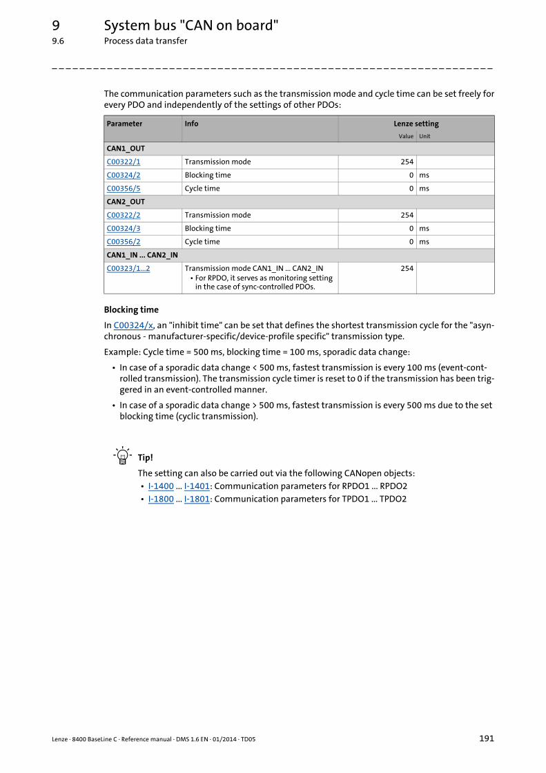
Lenze · 8400 BaseLine C · Reference manual · DMS 1.6 EN · 01/2014 · TD05 191
9 System bus "CAN on board"9.6 Process data transfer
_ _ _ _ _ _ _ _ _ _ _ _ _ _ _ _ _ _ _ _ _ _ _ _ _ _ _ _ _ _ _ _ _ _ _ _ _ _ _ _ _ _ _ _ _ _ _ _ _ _ _ _ _ _ _ _ _ _ _ _ _ _ _ _
The communication parameters such as the transmission mode and cycle time can be set freely forevery PDO and independently of the settings of other PDOs:
Blocking time
In C00324/x, an "inhibit time" can be set that defines the shortest transmission cycle for the "asyn-chronous - manufacturer-specific/device-profile specific" transmission type.
Example: Cycle time = 500 ms, blocking time = 100 ms, sporadic data change:
• In case of a sporadic data change < 500 ms, fastest transmission is every 100 ms (event-cont-rolled transmission). The transmission cycle timer is reset to 0 if the transmission has been trig-gered in an event-controlled manner.
• In case of a sporadic data change > 500 ms, fastest transmission is every 500 ms due to the set blocking time (cyclic transmission).
Tip!
The setting can also be carried out via the following CANopen objects:• I-1400 ... I-1401: Communication parameters for RPDO1 ... RPDO2• I-1800 ... I-1801: Communication parameters for TPDO1 ... TPDO2
Parameter Info Lenze setting
Value Unit
CAN1_OUT
C00322/1 Transmission mode 254
C00324/2 Blocking time 0 ms
C00356/5 Cycle time 0 ms
CAN2_OUT
C00322/2 Transmission mode 254
C00324/3 Blocking time 0 ms
C00356/2 Cycle time 0 ms
CAN1_IN ... CAN2_IN
C00323/1...2 Transmission mode CAN1_IN ... CAN2_IN• For RPDO, it serves as monitoring setting
in the case of sync-controlled PDOs.
254

9 System bus "CAN on board"9.6 Process data transfer
192 Lenze · 8400 BaseLine C · Reference manual · DMS 1.6 EN · 01/2014 · TD05
_ _ _ _ _ _ _ _ _ _ _ _ _ _ _ _ _ _ _ _ _ _ _ _ _ _ _ _ _ _ _ _ _ _ _ _ _ _ _ _ _ _ _ _ _ _ _ _ _ _ _ _ _ _ _ _ _ _ _ _ _ _ _ _
9.6.4 PDO synchronisation via sync telegram
During cyclic transmission, one or more PDOs are transmitted/received in fixed time intervals. Anadditional specific telegram, the so-called sync telegram, is used for synchronising cyclic process da-ta.
• The sync telegram is the trigger point for the transmission of process data from the slaves to the master and for the acceptance of process data from the master in the slaves.
• For sync-controlled process data processing, the sync telegram must be generated accordingly.
• The response to a sync telegram is determined by the selected transmission ty-pe.Transmission type ( 190)
Basic workflow
[9-6] Sync telegram
A. After the sync telegram has been received, the slaves transmit the synchronous process data to the master (TPDOs). The master reads them as process input data.
B. When the transmission process is completed, the slaves receive (RPDOs) the process output data (of the master).• All other telegrams (e.g. parameters or event-controlled process data) are accepted acyclically
by the slaves after the transmission is completed.• Illustration [9-6] does not include acyclic data. However, they need to be considered when di-
mensioning the cycle time.
C. The data are accepted in the slave with the next sync telegram if the Rx mode is set to 1 ... 240. If the Rx mode is 254 or 255, the data are accepted in the next device cycle, irrespective of the sync telegram.
Short overview: Parameters for the synchronisation via sync telegram
Sync cycle time
�SYNC SYNC
� � �
Parameter Info Lenze setting Assignment
Value Unit Sync master
Sync slave
C367 CAN Sync-Rx identifier 128
C368 CAN Sync-Tx-Identifier 128
C369 CAN Sync transmission cycle time 0 ms
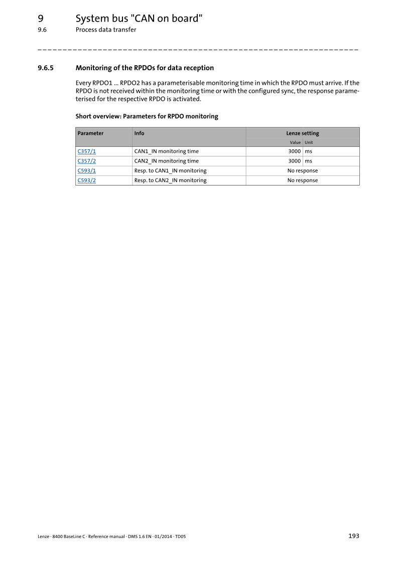
Lenze · 8400 BaseLine C · Reference manual · DMS 1.6 EN · 01/2014 · TD05 193
9 System bus "CAN on board"9.6 Process data transfer
_ _ _ _ _ _ _ _ _ _ _ _ _ _ _ _ _ _ _ _ _ _ _ _ _ _ _ _ _ _ _ _ _ _ _ _ _ _ _ _ _ _ _ _ _ _ _ _ _ _ _ _ _ _ _ _ _ _ _ _ _ _ _ _
9.6.5 Monitoring of the RPDOs for data reception
Every RPDO1 ... RPDO2 has a parameterisable monitoring time in which the RPDO must arrive. If theRPDO is not received within the monitoring time or with the configured sync, the response parame-terised for the respective RPDO is activated.
Short overview: Parameters for RPDO monitoring
Parameter Info Lenze setting
Value Unit
C357/1 CAN1_IN monitoring time 3000 ms
C357/2 CAN2_IN monitoring time 3000 ms
C593/1 Resp. to CAN1_IN monitoring No response
C593/2 Resp. to CAN2_IN monitoring No response
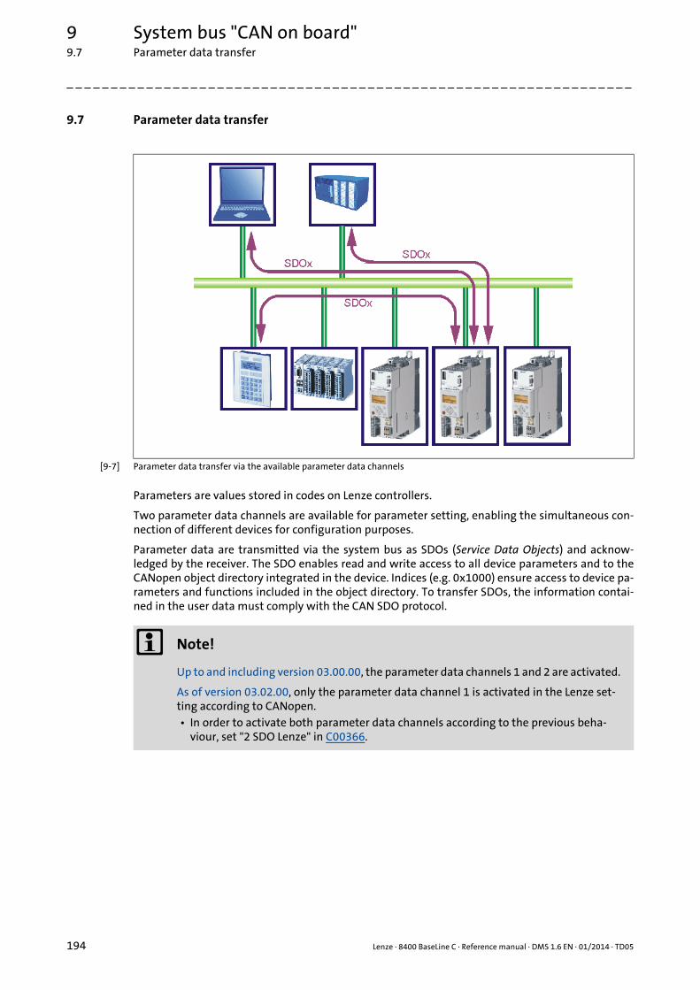
9 System bus "CAN on board"9.7 Parameter data transfer
194 Lenze · 8400 BaseLine C · Reference manual · DMS 1.6 EN · 01/2014 · TD05
_ _ _ _ _ _ _ _ _ _ _ _ _ _ _ _ _ _ _ _ _ _ _ _ _ _ _ _ _ _ _ _ _ _ _ _ _ _ _ _ _ _ _ _ _ _ _ _ _ _ _ _ _ _ _ _ _ _ _ _ _ _ _ _
9.7 Parameter data transfer
[9-7] Parameter data transfer via the available parameter data channels
Parameters are values stored in codes on Lenze controllers.
Two parameter data channels are available for parameter setting, enabling the simultaneous con-nection of different devices for configuration purposes.
Parameter data are transmitted via the system bus as SDOs (Service Data Objects) and acknow-ledged by the receiver. The SDO enables read and write access to all device parameters and to theCANopen object directory integrated in the device. Indices (e.g. 0x1000) ensure access to device pa-rameters and functions included in the object directory. To transfer SDOs, the information contai-ned in the user data must comply with the CAN SDO protocol.
Note!
Up to and including version 03.00.00, the parameter data channels 1 and 2 are activated.
As of version 03.02.00, only the parameter data channel 1 is activated in the Lenze set-ting according to CANopen.• In order to activate both parameter data channels according to the previous beha-
viour, set "2 SDO Lenze" in C00366.

Lenze · 8400 BaseLine C · Reference manual · DMS 1.6 EN · 01/2014 · TD05 195
9 System bus "CAN on board"9.7 Parameter data transfer
_ _ _ _ _ _ _ _ _ _ _ _ _ _ _ _ _ _ _ _ _ _ _ _ _ _ _ _ _ _ _ _ _ _ _ _ _ _ _ _ _ _ _ _ _ _ _ _ _ _ _ _ _ _ _ _ _ _ _ _ _ _ _ _
9.7.1 Identifiers of the parameter data objects
In the Lenze setting, the basic identifiers of the SDOs are preset according to the "Predefined Con-nection Set".
The identifiers of the parameter data objects SDO1 and SDO2 result from the basic identifier andthe node address set under code C350:
Identifier = basic identifier + node address
9.7.2 User data
Structure of the user data of the parameter data telegram
The following subchapters provide detailed information on user data.
Object Direction Lenze-Base-ID CANopen-Base-ID
from device to device dec hex dec hex
SDO1 (Parameter data channel 1)
TSDO1 1408 580 1408 580
RSDO1 1536 600 1536 600
SDO2(Parameter data channel 2)
TSDO2 1472 5C0 1472 5C0
RSDO2 1600 640 1600 640
Heartbeat 1792 700 1792 700
Boot-up 1792 700 1792 700
1st byte 2nd byte 3rd byte 4th byte 5th byte 6th byte 7th byte 8th byte
Command Index Subindex Data 1 Data 2 Data 3 Data 4
Low byte High byte Low word High word
Low byte High byte Low byte High byte
Note!
The user data are presented in the Motorola format.
Parameter data telegram examples ( 201)

9 System bus "CAN on board"9.7 Parameter data transfer
196 Lenze · 8400 BaseLine C · Reference manual · DMS 1.6 EN · 01/2014 · TD05
_ _ _ _ _ _ _ _ _ _ _ _ _ _ _ _ _ _ _ _ _ _ _ _ _ _ _ _ _ _ _ _ _ _ _ _ _ _ _ _ _ _ _ _ _ _ _ _ _ _ _ _ _ _ _ _ _ _ _ _ _ _ _ _
9.7.2.1 Command
The following commands can be transmitted or received for writing and reading the parameters:
More precisely, the command byte comprises the following information:
Tip!
More commands are defined in CANopen specification DS301, V4.02 (e.g. segmentedtransfer).
1st byte 2nd byte 3rd byte 4th byte 5th byte 6th byte 7th byte 8th byte
Command Index Subindex Data 1 Data 2 Data 3 Data 4
Low byte High byte Low word High word
Low byte High byte Low byte High byte
Command 1st byte Data length Info
hex dec
Write request 0x23 35 4 bytes Writing of a parameter to the controller.
0x2B 43 2 bytes
0x2F 47 1 byte
0x21 33 Block
Write response 0x60 96 4 bytes Controller acknowledges a write request.
Read request 0x40 64 4 bytes Reading of a parameter from the controller.
Read response 0x43 67 4 bytes Controller's response to a read request with the current pa-rameter value.
0x4B 75 2 bytes
0x4F 79 1 byte
0x41 65 Block
Error response 0x80 128 4 bytes Controller's response if the write/read request could not be executed correctly. Error messages ( 199)
Command 1st byte
Command specifier (cs) Toggle (t) Length* e s
Bit 7 Bit 6 Bit 5 Bit 4 Bit 3 Bit 2 Bit 1 Bit 0
Write request 0 0 1 0 0/1 0/1 1 1
Write response 0 1 1 0 0 0 0 0
Read request 0 1 0 0 0 0 0 0
Read response 0 1 0 0 0/1 0/1 1 1
Error response 1 0 0 0 0 0 0 0
*Bit coding of the length: 00 = 4 bytes, 01 = 3 bytes, 10 = 2 bytes, 11 = 1 bytee: expedited (shortened block service)
s: segmented (normal block service)
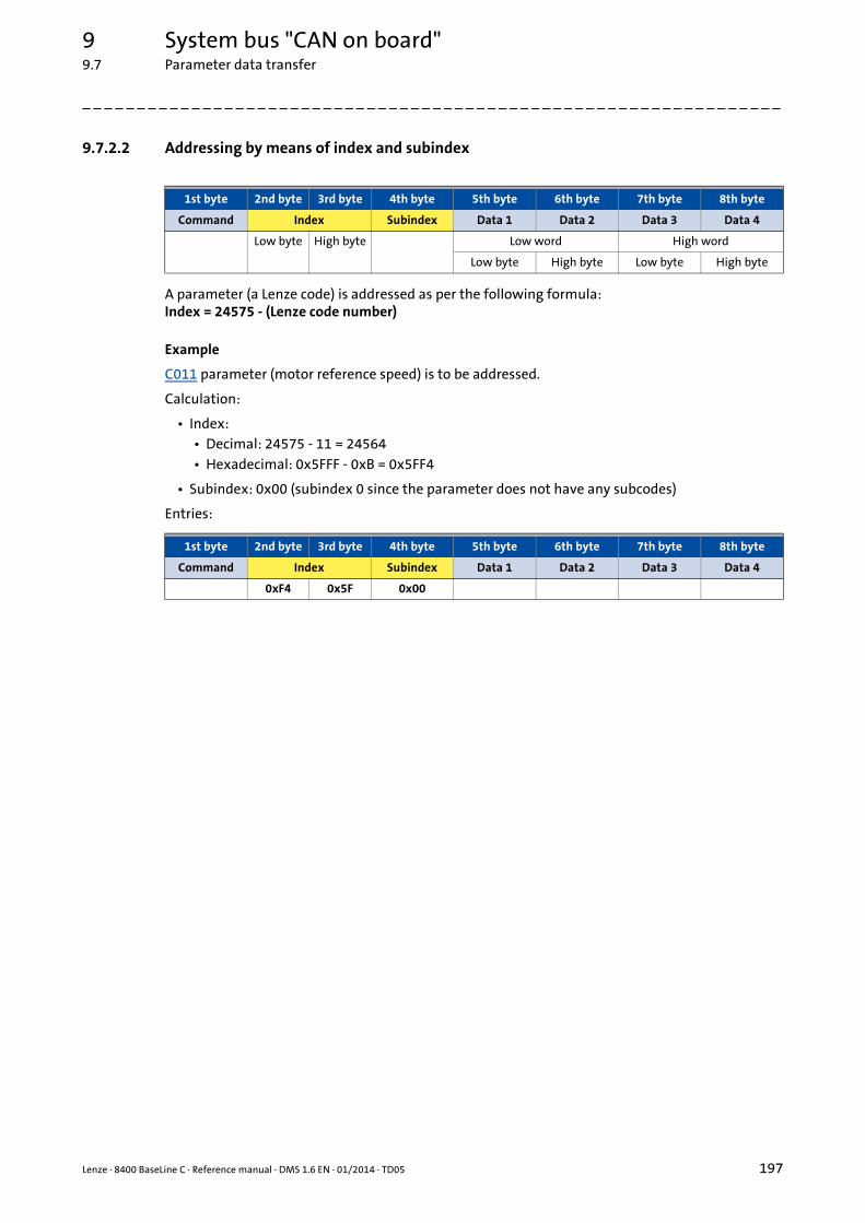
Lenze · 8400 BaseLine C · Reference manual · DMS 1.6 EN · 01/2014 · TD05 197
9 System bus "CAN on board"9.7 Parameter data transfer
_ _ _ _ _ _ _ _ _ _ _ _ _ _ _ _ _ _ _ _ _ _ _ _ _ _ _ _ _ _ _ _ _ _ _ _ _ _ _ _ _ _ _ _ _ _ _ _ _ _ _ _ _ _ _ _ _ _ _ _ _ _ _ _
9.7.2.2 Addressing by means of index and subindex
A parameter (a Lenze code) is addressed as per the following formula:Index = 24575 - (Lenze code number)
Example
C011 parameter (motor reference speed) is to be addressed.
Calculation:
• Index:• Decimal: 24575 - 11 = 24564• Hexadecimal: 0x5FFF - 0xB = 0x5FF4
• Subindex: 0x00 (subindex 0 since the parameter does not have any subcodes)
Entries:
1st byte 2nd byte 3rd byte 4th byte 5th byte 6th byte 7th byte 8th byte
Command Index Subindex Data 1 Data 2 Data 3 Data 4
Low byte High byte Low word High word
Low byte High byte Low byte High byte
1st byte 2nd byte 3rd byte 4th byte 5th byte 6th byte 7th byte 8th byte
Command Index Subindex Data 1 Data 2 Data 3 Data 4
0xF4 0x5F 0x00

9 System bus "CAN on board"9.7 Parameter data transfer
198 Lenze · 8400 BaseLine C · Reference manual · DMS 1.6 EN · 01/2014 · TD05
_ _ _ _ _ _ _ _ _ _ _ _ _ _ _ _ _ _ _ _ _ _ _ _ _ _ _ _ _ _ _ _ _ _ _ _ _ _ _ _ _ _ _ _ _ _ _ _ _ _ _ _ _ _ _ _ _ _ _ _ _ _ _ _
9.7.2.3 Data 1 ... Data 4
Maximally 4 bytes are available for parameter value entries. Depending on the data format, they areassigned as follows:
Example
A value of "123.45" is to be transmitted for a code, unit: "%" (e.g. C039/1: "Fixed setpoint-JOG1").
In controllers of the 8400 series, parameters with the "%" unit have two decimal positions and hencea scaling factor of "100".
Calculation:
• Value to be transmitted = scaling factor x value
• Data (1 ... 4) = 100 x 123.45 = 12345 (0x00 00 30 39)
Entries:
1st byte 2nd byte 3rd byte 4th byte 5th byte 6th byte 7th byte 8th byte
Command Index Subindex Data 1 Data 2 Data 3 Data 4
Low byte High byte Low word High word
Low byte High byte Low byte High byte
5th byte 6th byte 7th byte 8th byte
Parameter value (1 byte) 0x00 0x00 0x00
Parameter value (2 bytes) 0x00 0x00
Low byte High byte
Parameter value (4 bytes)
Low word High word
Low byte High byte Low byte High byte
Note!
The "Factor" column of the Table of attributes contains a so-called scaling factor for all Lenze parameters. The scaling factor is relevant to the transfer of parameter values which have one or more decimal positions in the parameter list.
If the scaling factor is > 1, the value must be multiplied by the indicated scaling factor prior to transmission to be able to transfer the value as an integer. At the SDO client end, the integer must be divided by the scaling factor to obtain the original value including decimal positions again.
1st byte 2nd byte 3rd byte 4th byte 5th byte 6th byte 7th byte 8th byte
Command Index Subindex Data 1 Data 2 Data 3 Data 4
0x39 0x30 0x00 0x00

Lenze · 8400 BaseLine C · Reference manual · DMS 1.6 EN · 01/2014 · TD05 199
9 System bus "CAN on board"9.7 Parameter data transfer
_ _ _ _ _ _ _ _ _ _ _ _ _ _ _ _ _ _ _ _ _ _ _ _ _ _ _ _ _ _ _ _ _ _ _ _ _ _ _ _ _ _ _ _ _ _ _ _ _ _ _ _ _ _ _ _ _ _ _ _ _ _ _ _
9.7.2.4 Error messages
In the event of an error, the addressed node generates a telegram with the "Error response" (0x80)command.
• The telegram includes the index and subindex of the code where the error occurred.
• The error code is entered in bytes 5 ... 8.• The error codes are standardised according to DS301, V4.02.• The representation of the error codes is provided in reverse read direction (see example be-
low).
Example
Representation of error code "0x06 04 00 41" in bytes 5 ... 8:
1st byte 2nd byte 3rd byte 4th byte 5th byte 6th byte 7th byte 8th byte
Command Index Subindex Error code
0x80(128)
Low byte High byte Low word High word
Low byte High byte Low byte High byte
1st byte 2nd byte 3rd byte 4th byte 5th byte 6th byte 7th byte 8th byte
Command Index Subindex Error code
0x41 0x00 0x04 0x06
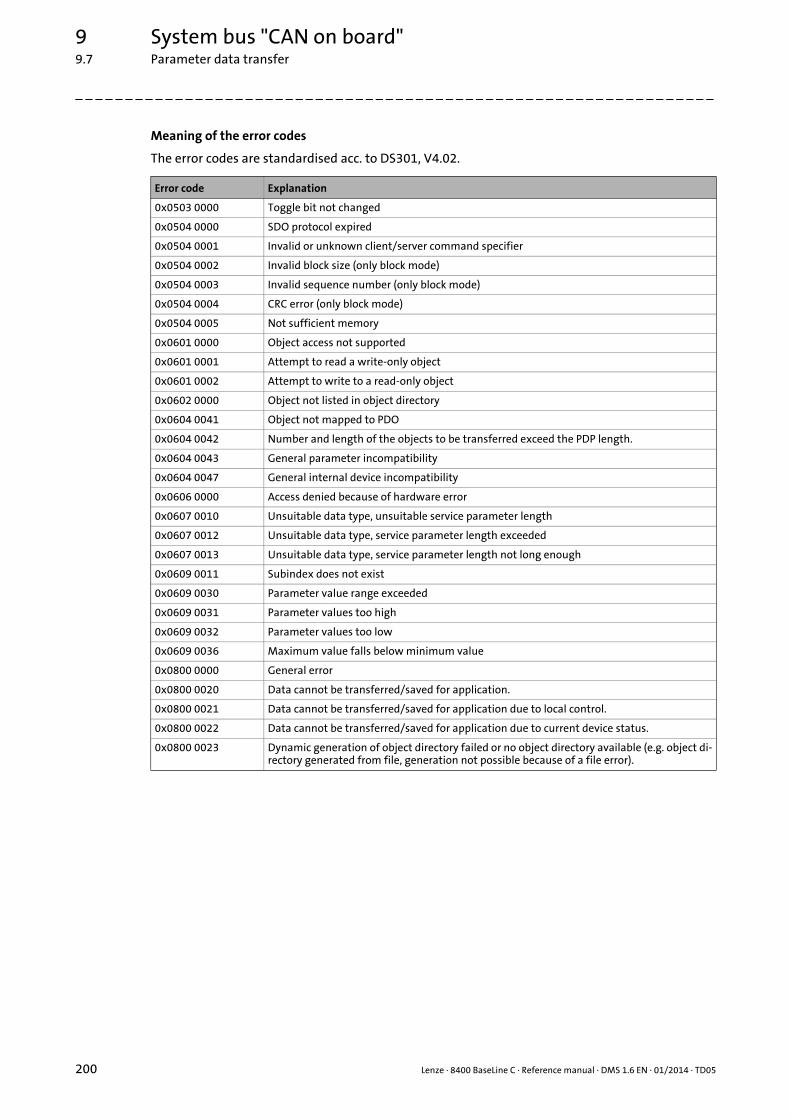
9 System bus "CAN on board"9.7 Parameter data transfer
200 Lenze · 8400 BaseLine C · Reference manual · DMS 1.6 EN · 01/2014 · TD05
_ _ _ _ _ _ _ _ _ _ _ _ _ _ _ _ _ _ _ _ _ _ _ _ _ _ _ _ _ _ _ _ _ _ _ _ _ _ _ _ _ _ _ _ _ _ _ _ _ _ _ _ _ _ _ _ _ _ _ _ _ _ _ _
Meaning of the error codes
The error codes are standardised acc. to DS301, V4.02.
Error code Explanation
0x0503 0000 Toggle bit not changed
0x0504 0000 SDO protocol expired
0x0504 0001 Invalid or unknown client/server command specifier
0x0504 0002 Invalid block size (only block mode)
0x0504 0003 Invalid sequence number (only block mode)
0x0504 0004 CRC error (only block mode)
0x0504 0005 Not sufficient memory
0x0601 0000 Object access not supported
0x0601 0001 Attempt to read a write-only object
0x0601 0002 Attempt to write to a read-only object
0x0602 0000 Object not listed in object directory
0x0604 0041 Object not mapped to PDO
0x0604 0042 Number and length of the objects to be transferred exceed the PDP length.
0x0604 0043 General parameter incompatibility
0x0604 0047 General internal device incompatibility
0x0606 0000 Access denied because of hardware error
0x0607 0010 Unsuitable data type, unsuitable service parameter length
0x0607 0012 Unsuitable data type, service parameter length exceeded
0x0607 0013 Unsuitable data type, service parameter length not long enough
0x0609 0011 Subindex does not exist
0x0609 0030 Parameter value range exceeded
0x0609 0031 Parameter values too high
0x0609 0032 Parameter values too low
0x0609 0036 Maximum value falls below minimum value
0x0800 0000 General error
0x0800 0020 Data cannot be transferred/saved for application.
0x0800 0021 Data cannot be transferred/saved for application due to local control.
0x0800 0022 Data cannot be transferred/saved for application due to current device status.
0x0800 0023 Dynamic generation of object directory failed or no object directory available (e.g. object di-rectory generated from file, generation not possible because of a file error).

Lenze · 8400 BaseLine C · Reference manual · DMS 1.6 EN · 01/2014 · TD05 201
9 System bus "CAN on board"9.7 Parameter data transfer
_ _ _ _ _ _ _ _ _ _ _ _ _ _ _ _ _ _ _ _ _ _ _ _ _ _ _ _ _ _ _ _ _ _ _ _ _ _ _ _ _ _ _ _ _ _ _ _ _ _ _ _ _ _ _ _ _ _ _ _ _ _ _ _
9.7.3 Parameter data telegram examples
9.7.3.1 Read parameters
Task: The heatsink temperature of 43 °C (code C061, data format INTEGER16, scaling factor 1) of thecontroller with node address "5" is to be read.
Telegram to drive
Response telegram from drive (if data have been correctly transmitted)
Identifier User data
1st byte 2nd byte 3rd byte 4th byte 5th byte 6th byte 7th byte 8th byte
Command Index Subindex Data 1 Data 2 Data 3 Data 4
0x0605 0x40 0xC2 0x5F 0x00 0x00 0x00 0x00 0x00
Explanations on the telegram to the drive
Identifier = 1536 + node address = 1536 + 5 = 1541 = 0x0605(1536 = SDO1 basic identifier to the controller)
Command = 0x40 = "Read request" (request to read a parameter from the controller)
Index = 24575 - code number = 24575 - 61 = 24514 = 0x5FC2
Subindex = 0 (code C061 has no subcodes)
Identifier User data
1st byte 2nd byte 3rd byte 4th byte 5th byte 6th byte 7th byte 8th byte
Command Index Subindex Data 1 Data 2 - -
0x0585 0x4B 0xC2 0x5F 0x00 0x2B 0x00 - -
Explanations on the telegram from the drive
Identifier = 1408 + node address = 1408 + 5 = 1413 = 0x0585(1408 = SDO1 basic identifier from the controller)
Command = 0x4B = "Read response" (response to the read request with current value)
Index as in telegram to the drive
Subindex
Data 1 ... 2 = 0x002B = 43 [°C]

9 System bus "CAN on board"9.7 Parameter data transfer
202 Lenze · 8400 BaseLine C · Reference manual · DMS 1.6 EN · 01/2014 · TD05
_ _ _ _ _ _ _ _ _ _ _ _ _ _ _ _ _ _ _ _ _ _ _ _ _ _ _ _ _ _ _ _ _ _ _ _ _ _ _ _ _ _ _ _ _ _ _ _ _ _ _ _ _ _ _ _ _ _ _ _ _ _ _ _
9.7.3.2 Write parameters
Task: The rated current of the connected motor is to be entered with Irated = 10.20 A (code C088)into the controller with node address "2".
Telegram to drive
Response telegram from drive (if data have been correctly transmitted)
Data 1 ... 4 Calculation
Value for motor current, (data type U16; display factor 1/100) 10.20 x 100 = 1020 (0x03 FC)
Identifier User data
1st byte 2nd byte 3rd byte 4th byte 5th byte 6th byte 7th byte 8th byte
Command Index Subindex Data 1 Data 2 Data 3 Data 4
0x0602 0x23 0xA7 0x5F 0x00 0xFC 0x03 0x00 0x00
Explanations on the telegram to the drive
Identifier = 1536 + node address = 1536 + 2 = 1538 = 0x0602(1536 = SDO1 basic identifier to the controller)
Command = 0x23 = "Write request" (request to write a parameter to the controller)
Index = 24575 - code number = 24575 - 88 = 24487 = 0x5FA7
Subindex = 0 (code C088 has no subcodes)
Data 1 ... 4 = 10.20 x 100 = 1020 = 0x000003FC(motor current value; data type U32; display factor 1/100)
Identifier User data
1st byte 2nd byte 3rd byte 4th byte 5th byte 6th byte 7th byte 8th byte
Command Index Subindex Data 1 Data 2 Data 3 Data 4
0x0582 0x60 0xA7 0x5F 0x00 0x00 0x00 0x00 0x00
Explanations on the telegram from the drive
Identifier = 1408 + node address = 1408 + 2 = 1410 = 0x0582(1408 = SDO1 basic identifier from the controller)
Command = 0x60 = "Write response" (acknowledgement of the write access from the controller)
Index as in telegram to the drive
Subindex

Lenze · 8400 BaseLine C · Reference manual · DMS 1.6 EN · 01/2014 · TD05 203
9 System bus "CAN on board"9.7 Parameter data transfer
_ _ _ _ _ _ _ _ _ _ _ _ _ _ _ _ _ _ _ _ _ _ _ _ _ _ _ _ _ _ _ _ _ _ _ _ _ _ _ _ _ _ _ _ _ _ _ _ _ _ _ _ _ _ _ _ _ _ _ _ _ _ _ _
9.7.3.3 Read block parameters
Task: The firmware version (code C099) to be read from the parameter set of the controller withnode address "12". The firmware version has a length of 11 ASCII characters which are transmittedas a block parameter. Depending on the block, the data width from the 2nd to 8th byte is assignedwithin the user data.
Telegram 1 to the drive: Read request
Response telegram 1 from the drive: Indication of the block length (11 characters)
Identifier User data
1st byte 2nd byte 3rd byte 4th byte 5th byte 6th byte 7th byte 8th byte
Command Index Subindex Data 1 Data 2 Data 3 Data 4
0x060C 0x40 0x9C 0x5F 0x00 0x00 0x00 0x00 0x00
Explanations on the telegram to the drive
Identifier = 1536 + node address = 1536 + 12 = 1548 = 0x060C(1536 = SDO1 basic identifier to the controller)
Command = 0x40 = "Read request" (request to read a parameter from the controller)
Index = 24575 - code number = 24575 - 99 = 24476 = 0x5F9C
Subindex = 0 (code C099 has no subcodes)
Identifier User data
1st byte 2nd byte 3rd byte 4th byte 5th byte 6th byte 7th byte 8th byte
Command Index Subindex Data 1 Data 2 Data 3 Data 4
0x058C 0x41 0x9C 0x5F 0x00 0x0B 0x00 0x00 0x00
Explanations on the telegram from the drive
Identifier = 1408 + node address = 1408 + 12 = 1420 = 0x058C(1408 = SDO1 basic identifier from the controller)
Command = 0x41 = "Read response" (response is block telegram)
Index as in telegram to the drive
Subindex
Data 1 ... 4 = 0x0000000B = data length of 11 characters in the ASCII format

9 System bus "CAN on board"9.7 Parameter data transfer
204 Lenze · 8400 BaseLine C · Reference manual · DMS 1.6 EN · 01/2014 · TD05
_ _ _ _ _ _ _ _ _ _ _ _ _ _ _ _ _ _ _ _ _ _ _ _ _ _ _ _ _ _ _ _ _ _ _ _ _ _ _ _ _ _ _ _ _ _ _ _ _ _ _ _ _ _ _ _ _ _ _ _ _ _ _ _
Telegram 2 to the drive: Request of the 1st data block
Response telegram 2 from the drive: Transmission of the 1st data block
Identifier User data
1st byte 2nd byte 3rd byte 4th byte 5th byte 6th byte 7th byte 8th byte
Command Data 1 Data 2 Data 3 Data 4 Data 5 Data 6 Data 7
0x060C 0x60 0x00 0x00 0x00 0x00 0x00 0x00 0x00
Explanations on the telegram to the drive
Command = 0x60 = "Read segment request" (request: read data block)• Bit 4 = 0 (toggle bit)
Influence of the toggle bit on the request commandThe blocks are toggled one after another, i.e. the request ist made with the "0x60" (= 0110*0000bin) command, then with the "0x70" (= 0111*0000bin) command, and then again with the "0x60" command, etc.* Toggle bit
Identifier User data
1st byte 2nd byte 3rd byte 4th byte 5th byte 6th byte 7th byte 8th byte
Command Data 1 Data 2 Data 3 Data 4 Data 5 Data 6 Data 7
0x058C 0x00 0x30 0x31 0x2E 0x30 0x30 0x2E 0x30
0asc 1asc .asc 0asc 0asc .asc 0asc
Explanations on the telegram to the drive
Command = 0x00 = 00000000bin• Bit 4 = 0 (toggle bit)
Influence of the toggle bit on the transmission command• The 1st response of the controller in the command byte is "0x0000*0000bin" if bytes 2 ... 8 are
completely filled with data and other telegrams are following.• The 2nd response of the controller in the command byte is "0x0001*0000bin" if bytes 2 ... 8
are completely filled with data and other telegrams are following, etc.* Toggle bit
Data 1 ... 7 = "01.00.0" (ASCII representation)

Lenze · 8400 BaseLine C · Reference manual · DMS 1.6 EN · 01/2014 · TD05 205
9 System bus "CAN on board"9.7 Parameter data transfer
_ _ _ _ _ _ _ _ _ _ _ _ _ _ _ _ _ _ _ _ _ _ _ _ _ _ _ _ _ _ _ _ _ _ _ _ _ _ _ _ _ _ _ _ _ _ _ _ _ _ _ _ _ _ _ _ _ _ _ _ _ _ _ _
Telegram 3 to the drive: Request of the 2nd data block
Response telegram 3 from the drive: Transmission of the 2nd data block including end identifier
Identifier User data
1st byte 2nd byte 3rd byte 4th byte 5th byte 6th byte 7th byte 8th byte
Command Data 1 Data 2 Data 3 Data 4 Data 5 Data 6 Data 7
0x060C 0x70 0x00 0x00 0x00 0x00 0x00 0x00 0x00
Explanations on telegram 3 to the drive
Command = 0x70 = "Read segment request" (request: read data block)• Bit 4 = 1 (toggle bit)
Identifier User data
1st byte 2nd byte 3rd byte 4th byte 5th byte 6th byte 7th byte 8th byte
Command Data 1 Data 2 Data 3 Data 4 Data 5 Data 6 Data 7
0x058C 0x17 0x30 0x2E 0x30 0x30 0x00 0x00 0x00
0asc .asc 0asc 0asc - - -
Explanations on telegram 3 from the drive
Command = 0x17 = 00010111bin:• Bit 0 = 1 (end of transmission)• Bit 1 ... bit 3 = 011bin (3 bytes do not contain any data)• Bit 4 = 1 (toggle bit)
Influence of the final bit and the residual data length on the transmission command• The end of transmission is signalled via the set final bit 0.• Bits 1 ... 3 reveal the number of bytes that do not contain any data anymore.
* Toggle bit
Data 1 ... 7 = "0.00" (ASCII representation)The result of the data block transmission is: "01.00.00.00"

9 System bus "CAN on board"9.8 Monitoring
206 Lenze · 8400 BaseLine C · Reference manual · DMS 1.6 EN · 01/2014 · TD05
_ _ _ _ _ _ _ _ _ _ _ _ _ _ _ _ _ _ _ _ _ _ _ _ _ _ _ _ _ _ _ _ _ _ _ _ _ _ _ _ _ _ _ _ _ _ _ _ _ _ _ _ _ _ _ _ _ _ _ _ _ _ _ _
9.8 Monitoring
9.8.1 Integrated error detection
If a node detects an error, it rejects the CAN telegram bits received so far and transmits an error flag.The error flag consists of 6 consecutive bits with the same logic value.
The following errors are detected:
Bit error
The sending node follows the transmission on the bus and interrupts the transmission if it receivesa different logic value than the value transmitted. With the next bit, the sending node starts thetransmission of an error flag.
In the arbitration phase, the transmitter only detects a bit error if a dominantly sent bit is receivedas recessive bit. In the ACK slot as well, the dominant overwriting of a recessive bit is not indicatedas a bit error.
Stuff-bit error
If more than 5 consecutive bits have the same logic value before the ACK delimiter in the CAN tele-gram, the previously transmitted telegram will be rejected and an error flag will be sent with thenext bit.
CRC error
If the received CRC checksum does not correspond to the checksum calculated in the CAN chip, theCAN controller will send an error flag after the ACK delimiter and the previously transmitted tele-gram will be annulled.
Acknowledgement error
If the sent ACK slot recessively sent by the transmitting node is not dominantly overwritten by a re-ceiver, the transmitting node will cancel the transmission. The transmitting node will annul thetransmitted telegram and will send an error flags with the next bit.
Format error
If a dominant bit is detected in the CRC delimiter, in the ACK delimiter or in the first 6 bits of the EOFfield, the received telegram will be rejected and an error flag will be sent with the next bit.

Lenze · 8400 BaseLine C · Reference manual · DMS 1.6 EN · 01/2014 · TD05 207
9 System bus "CAN on board"9.8 Monitoring
_ _ _ _ _ _ _ _ _ _ _ _ _ _ _ _ _ _ _ _ _ _ _ _ _ _ _ _ _ _ _ _ _ _ _ _ _ _ _ _ _ _ _ _ _ _ _ _ _ _ _ _ _ _ _ _ _ _ _ _ _ _ _ _
9.8.2 Heartbeat protocol
The heartbeat protocol can be used for node monitoring purposes within a CAN network.
Basic workflow
[9-8] Heartbeat protocol
1. A heartbeat producer cyclically transmits a so-called heartbeat telegram to one or more consu-mers.
2. The consumer(s) monitor the heartbeat telegram for arrival on a regular basis.
9.8.2.1 Telegram structure
• The heartbeat telegram of the producer has the following identifier:Identifier (COB-ID) = 1792 + producer's node address
• The user data (1 byte) contain the status (s) of the producer:
r: Reserved (always 0)s: Status of the producer (0: Boot-up, 4: Stopped, 5: Operational, 127: Pre-Operational)
Heartbeat producer status Data
Communication status Decimal value(s)
(r) Producer status (s)
Bit 7 Bit 6 Bit 5 Bit 4 Bit 3 Bit 2 Bit 1 Bit 0
Boot-up 0 0 0 0 0 0 0 0 0
Stopped 4 0 0 0 0 0 1 0 0
Operational 5 0 0 0 0 0 1 0 1
Pre-Operational 127 0 1 1 1 1 1 1 1
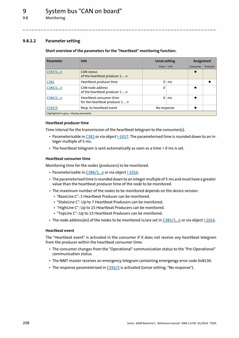
9 System bus "CAN on board"9.8 Monitoring
208 Lenze · 8400 BaseLine C · Reference manual · DMS 1.6 EN · 01/2014 · TD05
_ _ _ _ _ _ _ _ _ _ _ _ _ _ _ _ _ _ _ _ _ _ _ _ _ _ _ _ _ _ _ _ _ _ _ _ _ _ _ _ _ _ _ _ _ _ _ _ _ _ _ _ _ _ _ _ _ _ _ _ _ _ _ _
9.8.2.2 Parameter setting
Short overview of the parameters for the "Heartbeat" monitoring function:
Heartbeat producer time
Time interval for the transmission of the heartbeat telegram to the consumer(s).
• Parameterisable in C381 or via object I-1017. The parameterised time is rounded down to an in-teger multiple of 5 ms.
• The heartbeat telegram is sent automatically as soon as a time > 0 ms is set.
Heartbeat consumer time
Monitoring time for the nodes (producers) to be monitored.
• Parameterisable in C386/1...n or via object I-1016.
• The parameterised time is rounded down to an integer multiple of 5 ms and must have a greater value than the heartbeat producer time of the node to be monitored.
• The maximum number of the nodes to be monitored depends on the device version:• "BaseLine C": 1 Heartbeat Producer can be monitored.• "StateLine C": Up to 7 Heartbeat Producers can be monitored.• "HighLine C": Up to 15 Heartbeat Producers can be monitored.• "TopLine C": Up to 15 Heartbeat Producers can be monitored.
• The node address(es) of the nodes to be monitored is/are set in C385/1...n or via object I-1016.
Heartbeat event
The "Heartbeat event" is activated in the consumer if it does not receive any heartbeat telegramfrom the producer within the heartbeat consumer time:
• The consumer changes from the "Operational" communication status to the "Pre-Operational" communication status.
• The NMT master receives an emergency telegram containing emergengy error code 0x8130.
• The response parameterised in C592/5 is activated (Lenze setting: "No response").
Parameter Info Lenze setting Assignment
Value Unit Consumer Producer
C347/1...n CAN statusof the heartbeat producer 1 ... n
-
C381 Heartbeat producer time 0 ms
C385/1...n CAN node addressof the heartbeat producer 1 ... n
0
C386/1...n Heartbeat consumer timefor the heartbeat producer 1 ... n
0 ms
C592/5 Resp. to heartbeat event No response
Highlighted in grey = display parameter

Lenze · 8400 BaseLine C · Reference manual · DMS 1.6 EN · 01/2014 · TD05 209
9 System bus "CAN on board"9.8 Monitoring
_ _ _ _ _ _ _ _ _ _ _ _ _ _ _ _ _ _ _ _ _ _ _ _ _ _ _ _ _ _ _ _ _ _ _ _ _ _ _ _ _ _ _ _ _ _ _ _ _ _ _ _ _ _ _ _ _ _ _ _ _ _ _ _
9.8.2.3 Commissioning example
Task
An 8400 controller (node 2) which is configured as heartbeat consumer is to monitor another 8400controller (heartbeat producer, node 1).
• The heartbeat producer is to transmit a heartbeat telegram to the heartbeat consumer every 10 ms.
• The heartbeat consumer monitors the heartbeat telegram for arrival. A response is to be activa-ted in the event of an error.
Parameterising the heartbeat producer (node 1)
1. Set the heartbeat producer time (C381) to 10 ms.
Parameterising the heartbeat consumer (node 2)
1. Set the CAN node address of the producer in C385/1.
2. Set the heartbeat consumer time in C386/1.• Note: The heartbeat consumer time must be greater than the heartbeat producer time of the
node to be monitored set in C381.
3. Set the desired response in C592/5 which is to be activated should a heartbeat event in the con-sumer occur.
Tip!
In C347/1...n displays the heartbeat status of the monitored nodes.
Heartbeat telegram
• The heartbeat telegram of the producer has the following identifier:Identifier (COB-ID) = 1792 + producer's node address = 1792 + 1 = 1793 = 0x701
Note!
The heartbeat monitoring will not start until the first heartbeat telegram of a monitored producer has been received successfully and the "Pre-Operational" NMT status has been assumed.
The boot-up telegram counts as the first heartbeat telegram.
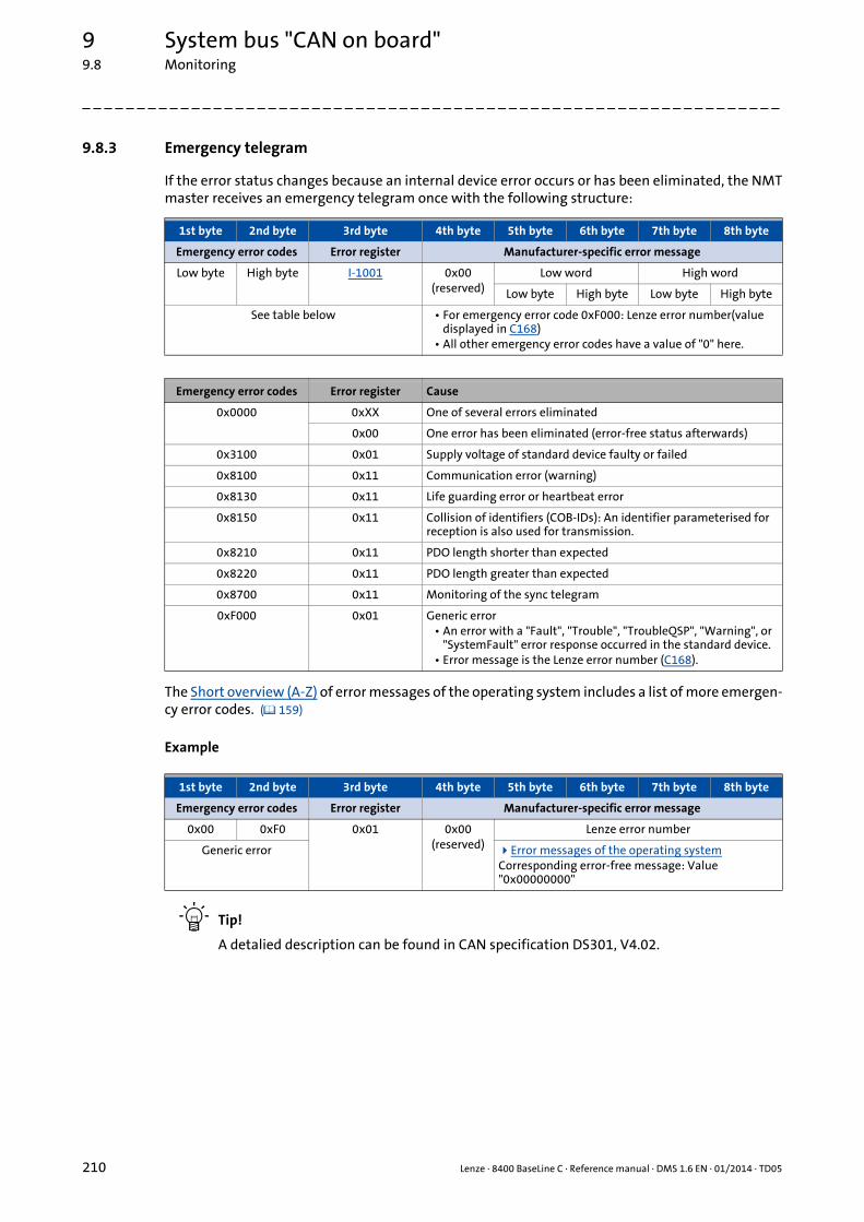
9 System bus "CAN on board"9.8 Monitoring
210 Lenze · 8400 BaseLine C · Reference manual · DMS 1.6 EN · 01/2014 · TD05
_ _ _ _ _ _ _ _ _ _ _ _ _ _ _ _ _ _ _ _ _ _ _ _ _ _ _ _ _ _ _ _ _ _ _ _ _ _ _ _ _ _ _ _ _ _ _ _ _ _ _ _ _ _ _ _ _ _ _ _ _ _ _ _
9.8.3 Emergency telegram
If the error status changes because an internal device error occurs or has been eliminated, the NMTmaster receives an emergency telegram once with the following structure:
The Short overview (A-Z) of error messages of the operating system includes a list of more emergen-cy error codes. ( 159)
Example
Tip!
A detalied description can be found in CAN specification DS301, V4.02.
1st byte 2nd byte 3rd byte 4th byte 5th byte 6th byte 7th byte 8th byte
Emergency error codes Error register Manufacturer-specific error message
Low byte High byte I-1001 0x00(reserved)
Low word High word
Low byte High byte Low byte High byte
See table below • For emergency error code 0xF000: Lenze error number(value displayed in C168)
• All other emergency error codes have a value of "0" here.
Emergency error codes Error register Cause
0x0000 0xXX One of several errors eliminated
0x00 One error has been eliminated (error-free status afterwards)
0x3100 0x01 Supply voltage of standard device faulty or failed
0x8100 0x11 Communication error (warning)
0x8130 0x11 Life guarding error or heartbeat error
0x8150 0x11 Collision of identifiers (COB-IDs): An identifier parameterised for reception is also used for transmission.
0x8210 0x11 PDO length shorter than expected
0x8220 0x11 PDO length greater than expected
0x8700 0x11 Monitoring of the sync telegram
0xF000 0x01 Generic error• An error with a "Fault", "Trouble", "TroubleQSP", "Warning", or
"SystemFault" error response occurred in the standard device.• Error message is the Lenze error number (C168).
1st byte 2nd byte 3rd byte 4th byte 5th byte 6th byte 7th byte 8th byte
Emergency error codes Error register Manufacturer-specific error message
0x00 0xF0 0x01 0x00(reserved)
Lenze error number
Generic error Error messages of the operating systemCorresponding error-free message: Value "0x00000000"

Lenze · 8400 BaseLine C · Reference manual · DMS 1.6 EN · 01/2014 · TD05 211
9 System bus "CAN on board"9.9 Implemented CANopen objects
_ _ _ _ _ _ _ _ _ _ _ _ _ _ _ _ _ _ _ _ _ _ _ _ _ _ _ _ _ _ _ _ _ _ _ _ _ _ _ _ _ _ _ _ _ _ _ _ _ _ _ _ _ _ _ _ _ _ _ _ _ _ _ _
9.9 Implemented CANopen objects
Lenze devices can both be parameterised with Lenze codes and manufacturer-independent "CANo-pen objects". A completely CANopen-compliant communication can only be achieved by using CA-Nopen objects for parameter setting. The CANopen objects described in this chapter are defined inthe CAN specification DS301 V4.02.
Many CANopen objects can be mapped on Lenze codes. In the following table, the correspondingLenze codes are listed in the column "Relationship to Lenze codes".
Overview of CANopen indices and their relationship to Lenze codes
Note!
Some of the terms used here derive from the CANopen protocol.
CANopen object Relationship to Lenze code
Index Subindex Name
I-1000 0 Device type -
I-1001 0 Error register -
I-1003 Predefined error field
0 Number of errors -
1 ... 10 Standard error field -
I-1005 0 COB-ID SYNC message C367
C368
I-1006 0 Communication cycle period C369
I-1014 0 COB-ID EMCY -
I-1016 Consumer heartbeat time
0 Highest subindex supported -
1 ... n Consumer heartbeat time• "BaseLine C" version: n = 1• "StateLine C" version: n = 7• "HighLine C" version: n = 15• "TopLine C" version: n = 15
C385/1...nC386/1...n
I-1017 0 Producer heartbeat time C381
I-1018 Identity object
0 Highest subindex supported -
1 Vendor ID -
2 Product code -
3 Revision number -
4 Serial number -
I-1200 SDO1 server parameter
0 Highest subindex supported -
1 COB-ID client −> server (rx) -
2 COB-ID server −> client (tx) -
I-1201 SDO2 server parameter
0 Highest subindex supported -
1 COB-ID client −> server (rx) -
2 COB-ID server −> client (tx) -
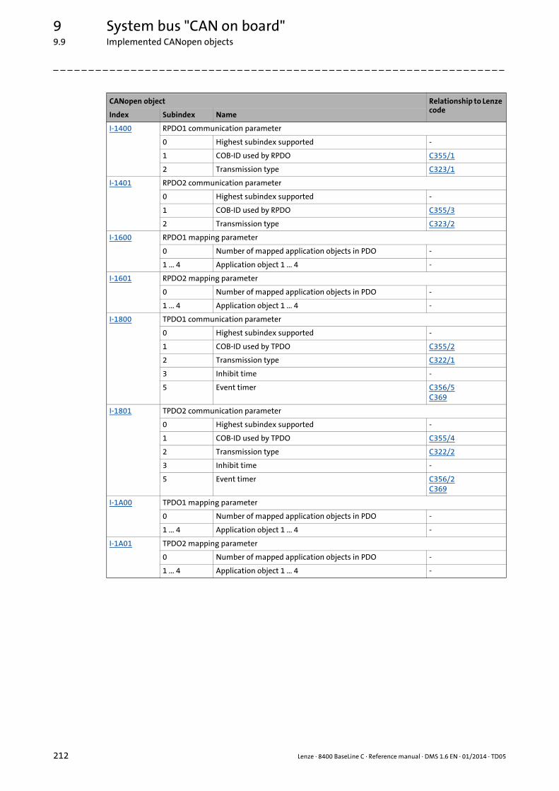
9 System bus "CAN on board"9.9 Implemented CANopen objects
212 Lenze · 8400 BaseLine C · Reference manual · DMS 1.6 EN · 01/2014 · TD05
_ _ _ _ _ _ _ _ _ _ _ _ _ _ _ _ _ _ _ _ _ _ _ _ _ _ _ _ _ _ _ _ _ _ _ _ _ _ _ _ _ _ _ _ _ _ _ _ _ _ _ _ _ _ _ _ _ _ _ _ _ _ _ _
I-1400 RPDO1 communication parameter
0 Highest subindex supported -
1 COB-ID used by RPDO C355/1
2 Transmission type C323/1
I-1401 RPDO2 communication parameter
0 Highest subindex supported -
1 COB-ID used by RPDO C355/3
2 Transmission type C323/2
I-1600 RPDO1 mapping parameter
0 Number of mapped application objects in PDO -
1 ... 4 Application object 1 ... 4 -
I-1601 RPDO2 mapping parameter
0 Number of mapped application objects in PDO -
1 ... 4 Application object 1 ... 4 -
I-1800 TPDO1 communication parameter
0 Highest subindex supported -
1 COB-ID used by TPDO C355/2
2 Transmission type C322/1
3 Inhibit time -
5 Event timer C356/5C369
I-1801 TPDO2 communication parameter
0 Highest subindex supported -
1 COB-ID used by TPDO C355/4
2 Transmission type C322/2
3 Inhibit time -
5 Event timer C356/2C369
I-1A00 TPDO1 mapping parameter
0 Number of mapped application objects in PDO -
1 ... 4 Application object 1 ... 4 -
I-1A01 TPDO2 mapping parameter
0 Number of mapped application objects in PDO -
1 ... 4 Application object 1 ... 4 -
CANopen object Relationship to Lenze code
Index Subindex Name

9 System bus "CAN on board"9.9 Implemented CANopen objects | I-1000
213 Lenze · 8400 BaseLine C · Reference manual · DMS 1.6 EN · 01/2014 · TD05
_ _ _ _ _ _ _ _ _ _ _ _ _ _ _ _ _ _ _ _ _ _ _ _ _ _ _ _ _ _ _ _ _ _ _ _ _ _ _ _ _ _ _ _ _ _ _ _ _ _ _ _ _ _ _ _ _ _ _ _ _ _ _ _
I-1000
The CANopen index I-1000 specifies the profile for this device. Furthermore, additional informationdefined in the device profile itself can be stored here.
[9-9] Data telegram assignment
In case of 8400 series controllers, the four bytes contain the following values:
• 5th and 6th byte: The data content is 0x0000, i.e. no profile definition.
• 7th byte: The data content specifies the device type: Here the value is 0x00 for controllers.
• 8th byte: The data content is 0x00.
The data content for the 8400 controller thus is: 00 00 00 00
I-1001
Error register
The error status in the data byte (U8) is bit coded. The following error states are coded in the databyte (U8):
Index
I-1000Name:
Device type
Subindex Default setting Display range (min. value | unit | max. value) Access Data type
0: Device type 0 0 4294967295 ro U32
8th byte 7th byte 6th byte 5th byte
Data 4 Data 3 Data 2 Data 1
High word Low word
High byte Low byte High byte Low byte
Additional information Device profile number
Index:
I-1001Name:
Error register
Subindex Default setting Display range (min. value | unit | max. value) Access Data type
0: Error register - 0 255 ro U8
Bit 7 Bit 6 Bit 5 Bit 4 Bit 3 Bit 2 Bit 1 Bit 0 Error status
0 0 0 0 0 0 0 0 No error
0 0 0 0 0 0 0 1 Device error message
0 0 0 1 0 0 0 1 Communication error

Lenze · 8400 BaseLine C · Reference manual · DMS 1.6 EN · 01/2014 · TD05 214
9 System bus "CAN on board"9.9 Implemented CANopen objects | I-1003
_ _ _ _ _ _ _ _ _ _ _ _ _ _ _ _ _ _ _ _ _ _ _ _ _ _ _ _ _ _ _ _ _ _ _ _ _ _ _ _ _ _ _ _ _ _ _ _ _ _ _ _ _ _ _ _ _ _ _ _ _ _ _ _
I-1003
Error history
This object indicates that an error has occurred in the module and in the standard device.
Index:
I-1003Name:
Predefined error field
Subindex Default setting Display range (min. value | unit | max. value) Access Data type
0: Number of errors 0 0 255 rw U8
1 ... 10: Standard error field - 0 4294967295 ro U32
Subindex Meaning
0 Number of saved error messages
1 ... 10 Display of the error listThe error messages (U32) consist of a 16-bit error code and a manufacturer-specific information field comprising 16 bits.
Note!
The values in the "standard error field" under subindex 1 ... 10 will be deleted if the sub-index "number of recorded errors" is overwritten with the value "0".
Emergencyerror codes
Cause Entry in theerror register
(I-1001)
0x0000 One of several errors eliminated 0xXX
Elimination of one single error (afterwards no more errors)
0x00
0x1000 Standard device is in error status (error response "fault", "message", "warning", "error", "quick stop by trouble", or "system error")
0x01
0x3100 Supply voltage of standard device faulty or failed 0x01
0x8100 Communication error (warning) 0x11
0x8130 Life guard error or heartbeat error 0x11
0x8150 Collision of COB-IDs: An ID parameterised for reception is also used for transmission.
0x11
0x8210 PDO length shorter than expected 0x11
0x8220 PDO length greater than expected 0x11
0x8700 Monitoring of the sync telegram 0x11
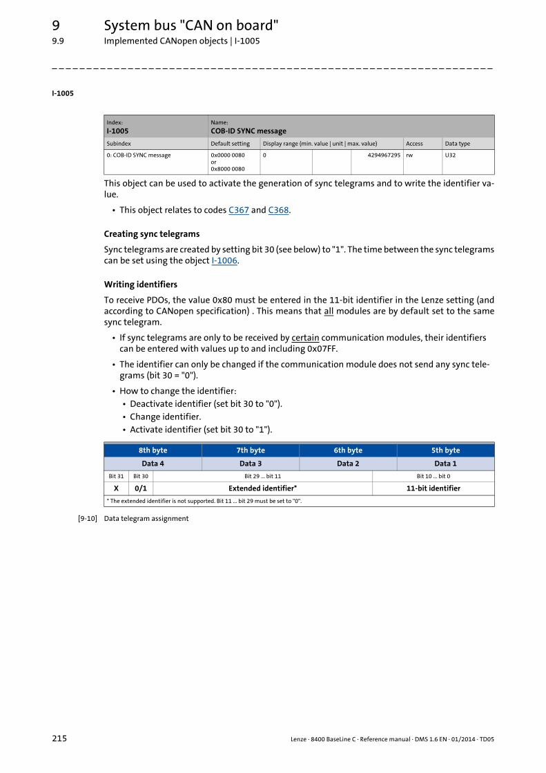
9 System bus "CAN on board"9.9 Implemented CANopen objects | I-1005
215 Lenze · 8400 BaseLine C · Reference manual · DMS 1.6 EN · 01/2014 · TD05
_ _ _ _ _ _ _ _ _ _ _ _ _ _ _ _ _ _ _ _ _ _ _ _ _ _ _ _ _ _ _ _ _ _ _ _ _ _ _ _ _ _ _ _ _ _ _ _ _ _ _ _ _ _ _ _ _ _ _ _ _ _ _ _
I-1005
This object can be used to activate the generation of sync telegrams and to write the identifier va-lue.
• This object relates to codes C367 and C368.
Creating sync telegrams
Sync telegrams are created by setting bit 30 (see below) to "1". The time between the sync telegramscan be set using the object I-1006.
Writing identifiers
To receive PDOs, the value 0x80 must be entered in the 11-bit identifier in the Lenze setting (andaccording to CANopen specification) . This means that all modules are by default set to the samesync telegram.
• If sync telegrams are only to be received by certain communication modules, their identifiers can be entered with values up to and including 0x07FF.
• The identifier can only be changed if the communication module does not send any sync tele-grams (bit 30 = "0").
• How to change the identifier:• Deactivate identifier (set bit 30 to "0").• Change identifier.• Activate identifier (set bit 30 to "1").
[9-10] Data telegram assignment
Index:
I-1005Name:
COB-ID SYNC message
Subindex Default setting Display range (min. value | unit | max. value) Access Data type
0: COB-ID SYNC message 0x0000 0080or0x8000 0080
0 4294967295 rw U32
8th byte 7th byte 6th byte 5th byte
Data 4 Data 3 Data 2 Data 1
Bit 31 Bit 30 Bit 29 ... bit 11 Bit 10 ... bit 0
X 0/1 Extended identifier* 11-bit identifier
* The extended identifier is not supported. Bit 11 ... bit 29 must be set to "0".
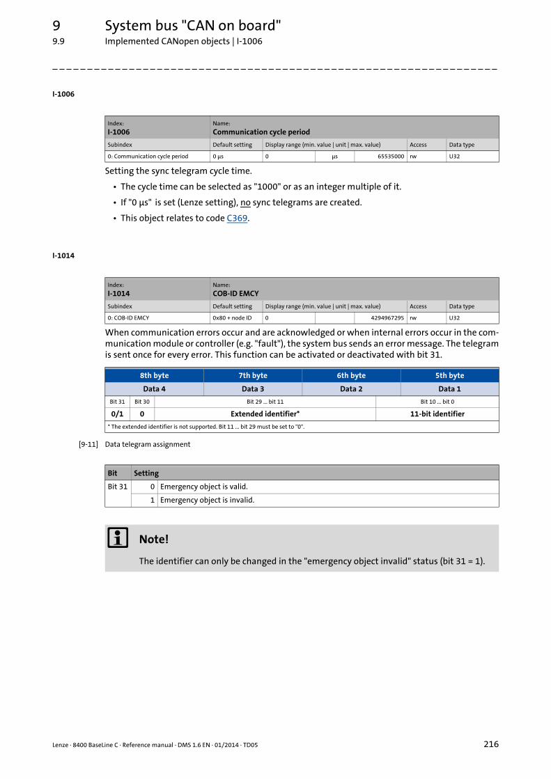
Lenze · 8400 BaseLine C · Reference manual · DMS 1.6 EN · 01/2014 · TD05 216
9 System bus "CAN on board"9.9 Implemented CANopen objects | I-1006
_ _ _ _ _ _ _ _ _ _ _ _ _ _ _ _ _ _ _ _ _ _ _ _ _ _ _ _ _ _ _ _ _ _ _ _ _ _ _ _ _ _ _ _ _ _ _ _ _ _ _ _ _ _ _ _ _ _ _ _ _ _ _ _
I-1006
Setting the sync telegram cycle time.
• The cycle time can be selected as "1000" or as an integer multiple of it.
• If "0 μs" is set (Lenze setting), no sync telegrams are created.
• This object relates to code C369.
I-1014
When communication errors occur and are acknowledged or when internal errors occur in the com-munication module or controller (e.g. "fault"), the system bus sends an error message. The telegramis sent once for every error. This function can be activated or deactivated with bit 31.
[9-11] Data telegram assignment
Index:
I-1006Name:
Communication cycle period
Subindex Default setting Display range (min. value | unit | max. value) Access Data type
0: Communication cycle period 0 μs 0 μs 65535000 rw U32
Index:
I-1014Name:
COB-ID EMCY
Subindex Default setting Display range (min. value | unit | max. value) Access Data type
0: COB-ID EMCY 0x80 + node ID 0 4294967295 rw U32
8th byte 7th byte 6th byte 5th byte
Data 4 Data 3 Data 2 Data 1
Bit 31 Bit 30 Bit 29 ... bit 11 Bit 10 ... bit 0
0/1 0 Extended identifier* 11-bit identifier
* The extended identifier is not supported. Bit 11 ... bit 29 must be set to "0".
Bit Setting
Bit 31 0 Emergency object is valid.
1 Emergency object is invalid.
Note!
The identifier can only be changed in the "emergency object invalid" status (bit 31 = 1).

9 System bus "CAN on board"9.9 Implemented CANopen objects | I-1016
217 Lenze · 8400 BaseLine C · Reference manual · DMS 1.6 EN · 01/2014 · TD05
_ _ _ _ _ _ _ _ _ _ _ _ _ _ _ _ _ _ _ _ _ _ _ _ _ _ _ _ _ _ _ _ _ _ _ _ _ _ _ _ _ _ _ _ _ _ _ _ _ _ _ _ _ _ _ _ _ _ _ _ _ _ _ _
I-1016
Monitoring time for the nodes to be monitored via heartbeat. Heartbeat protocol ( 207)
• The parameterised time is rounded down to an integer multiple of 5 ms and must have a greater value than the heartbeat producer time of the node to be monitored.
[9-12] Data telegram assignment
I-1017
Time interval for sending the heartbeat telegram to the consumer(s).Heartbeat protocol ( 207)
• The parameterised time is rounded down to an integer multiple of 5 ms.
• The heartbeat telegram is automatically sent as soon as a time > 0 ms is entered. In this case, the "node guarding" monitoring function is deactivated.
• This object relates to code C381.
Index:
I-1016Name:
Consumer heartbeat time
Subindex Default setting Display range (min. value | unit | max. value) Access Data type
0: Highest subindex supported BaseLine C: 1StateLine C: 7HighLine C: 15TopLine C: 15
- (read access only) ro U16
1 ... n: Consumer heartbeat time 0 0 65535 rw U16
Subindex Meaning Lenze code
0 Number of nodes to be monitored
1 ... n Node ID and heartbeat time of the node to be monitored Node ID:C385/xHeartbeat time:C386/x
8th byte 7th byte 6th byte 5th byte
Data 4 Data 3 Data 2 Data 1
Bit 31 ... bit 24 Bit 23 ... bit 16 Bit 15 ... bit 0
0(reserved)
Node ID Heartbeat timein [ms]
Index:
I-1017Name:
Producer heartbeat time
Subindex Default setting Display range (min. value | unit | max. value) Access Data type
0: Producer heartbeat time 0 0 ms 65535 rw U16

Lenze · 8400 BaseLine C · Reference manual · DMS 1.6 EN · 01/2014 · TD05 218
9 System bus "CAN on board"9.9 Implemented CANopen objects | I-1018
_ _ _ _ _ _ _ _ _ _ _ _ _ _ _ _ _ _ _ _ _ _ _ _ _ _ _ _ _ _ _ _ _ _ _ _ _ _ _ _ _ _ _ _ _ _ _ _ _ _ _ _ _ _ _ _ _ _ _ _ _ _ _ _
I-1018
I-1200
Identifiers for SDO server channel 1 (basic SDO channel).
• According to DS301 V4.02, the basic SDO channel can neither be changed nor deactivated.
[9-13] Data telegram assignment
Index:
I-1018Name:
Identity object
Subindex Default setting Display range (min. value | unit | max. value) Access Data type
0: Highest subindex supported see below 0 4294967295 ro U32
1: Vendor ID
2: Product code
3: Revision number
4: Serial number
Subindex Meaning
1 Manufacturer's identification number• The identification number allocated to Lenze by the organisation "CAN in Auto-
mation e. V." is "0x0000003B".
2 Product code
0x84001 8400 BaseLine C
0x84002 8400 StateLine C
0x84003 8400 HighLine C
0x84004 8400 TopLine C
3 Main and subversion of firmware
4 Serial number
Index:
I-1200Name:
SDO1 server parameter
Subindex Default setting Display range (min. value | unit | max. value) Access Data type
0: Highest subindex supported 2 2 2 ro U8
1: COB-ID client -> server (rx) node ID + 0x600 0 4294967295 ro U32
2: COB-ID server -> client (tx) node ID + 0x580 0 4294967295 ro U32
Subindex Meaning
1 Specification of receive identifier• For SDO server channel 1: node address (C350) + 0x580
2 Specification of send identifier• For SDO server channel 1: Node address (C350) + 0x580
8th byte 7th byte 6th byte 5th byte
Data 4 Data 3 Data 2 Data 1
Bit 31 Bit 30 Bit 29 ... bit 11 Bit 10 ... bit 0
0 0 Extended identifier* 11-bit identifier
* The extended identifier is not supported. Bit 11 ... bit 29 must be set to "0".
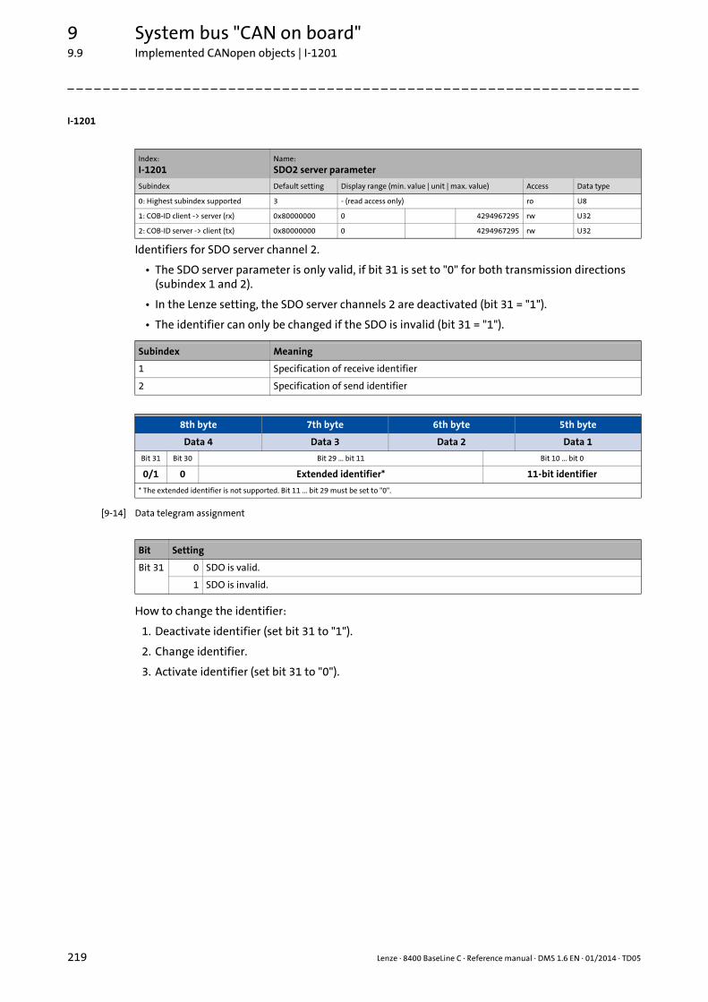
9 System bus "CAN on board"9.9 Implemented CANopen objects | I-1201
219 Lenze · 8400 BaseLine C · Reference manual · DMS 1.6 EN · 01/2014 · TD05
_ _ _ _ _ _ _ _ _ _ _ _ _ _ _ _ _ _ _ _ _ _ _ _ _ _ _ _ _ _ _ _ _ _ _ _ _ _ _ _ _ _ _ _ _ _ _ _ _ _ _ _ _ _ _ _ _ _ _ _ _ _ _ _
I-1201
Identifiers for SDO server channel 2.
• The SDO server parameter is only valid, if bit 31 is set to "0" for both transmission directions (subindex 1 and 2).
• In the Lenze setting, the SDO server channels 2 are deactivated (bit 31 = "1").
• The identifier can only be changed if the SDO is invalid (bit 31 = "1").
[9-14] Data telegram assignment
How to change the identifier:
1. Deactivate identifier (set bit 31 to "1").
2. Change identifier.
3. Activate identifier (set bit 31 to "0").
Index:
I-1201Name:
SDO2 server parameter
Subindex Default setting Display range (min. value | unit | max. value) Access Data type
0: Highest subindex supported 3 - (read access only) ro U8
1: COB-ID client -> server (rx) 0x80000000 0 4294967295 rw U32
2: COB-ID server -> client (tx) 0x80000000 0 4294967295 rw U32
Subindex Meaning
1 Specification of receive identifier
2 Specification of send identifier
8th byte 7th byte 6th byte 5th byte
Data 4 Data 3 Data 2 Data 1
Bit 31 Bit 30 Bit 29 ... bit 11 Bit 10 ... bit 0
0/1 0 Extended identifier* 11-bit identifier
* The extended identifier is not supported. Bit 11 ... bit 29 must be set to "0".
Bit Setting
Bit 31 0 SDO is valid.
1 SDO is invalid.

Lenze · 8400 BaseLine C · Reference manual · DMS 1.6 EN · 01/2014 · TD05 220
9 System bus "CAN on board"9.9 Implemented CANopen objects | I-1201
_ _ _ _ _ _ _ _ _ _ _ _ _ _ _ _ _ _ _ _ _ _ _ _ _ _ _ _ _ _ _ _ _ _ _ _ _ _ _ _ _ _ _ _ _ _ _ _ _ _ _ _ _ _ _ _ _ _ _ _ _ _ _ _
Example
Parameter data channel 2 of the controller with node address 4 shall be activated.
• For this, bit 31 must be set to "0" (≡ "SDO is valid") in subindices 1 and 2 of the object I-1201.
• The master must send the two "write request" commands to the nodes via the basic SDO chan-nel.
Identifier calculation
• Identifier (COB-ID) = basic identifier + node address (node ID)
• Basic identifier SDO2 from master to drive: 1600 (0x640) Identifier = 0x640 + 0x4 = 0x644
• Basic identifier SDO2 from drive to master: 1472 (0x5C0) Identifier = 0x5C0 + 0x4 = 0x5C4
Resulting data (data 1 ... data 4)
[9-15] Data telegram assignment for subindex 1
[9-16] Data telegram assignment for subindex 2
User data assignment
[9-17] User data assignment for writing to subindex 1
[9-18] User data assignment for writing to subindex 2
8th byte 7th byte 6th byte 5th byte
Data 4 Data 3 Data 2 Data 1
Bit 31 Bit 30 Bit 29 ... bit 11 Bit 10 ... bit 0
0 0 Extended identifier = 0 11-bit identifier = 0x644
0x00 0x00 0x06 0x44
8th byte 7th byte 6th byte 5th byte
Data 4 Data 3 Data 2 Data 1
Bit 31 Bit 30 Bit 29 ... bit 11 Bit 10 ... bit 0
0 0 Extended identifier = 0 11-bit identifier = 0x5C4
0x00 0x00 0x05 0xC4
1st byte 2nd byte 3rd byte 4th byte 5th byte 6th byte 7th byte 8th byte
Command Index Subindex Data 1 Data 2 Data 3 Data 4
0x23 0x01 0x12 0x01 0x44 0x06 0x00 0x00
1st byte 2nd byte 3rd byte 4th byte 5th byte 6th byte 7th byte 8th byte
Command Index Subindex Data 1 Data 2 Data 3 Data 4
0x23 0x01 0x12 0x02 0xC4 0x05 0x00 0x00

9 System bus "CAN on board"9.9 Implemented CANopen objects | I-1400
221 Lenze · 8400 BaseLine C · Reference manual · DMS 1.6 EN · 01/2014 · TD05
_ _ _ _ _ _ _ _ _ _ _ _ _ _ _ _ _ _ _ _ _ _ _ _ _ _ _ _ _ _ _ _ _ _ _ _ _ _ _ _ _ _ _ _ _ _ _ _ _ _ _ _ _ _ _ _ _ _ _ _ _ _ _ _
I-1400
Communication parameter for receiving process data via RPDO1
[9-19] Data telegram assignment
How to change the identifier:
1. Deactivate identifier (set bit 31 to "1").
2. Change identifier.
3. Activate identifier (set bit 31 to "0").
Description of subindex 1
[9-20] I-1400 ... I-1402, subindex 1
Index:
I-1400Name:
RPDO1 communication parameter
Subindex Default setting Display range (min. value | unit | max. value) Access Data type
0: Highest subindex supported 5 - (read access only) ro U8
1: COB-ID used by RPDO 0x200 + node ID 0 4294967295 rw U32
2: Transmission type 254 0 255 rw U8
3: Inhibit time - - (not used for RPDOs) rw U16
4: Compatibility entry - - (reserved, read or write access leads to error message 0x06090011)
rw U8
5: Event timer - - (not used for RPDOs) rw U16
Subindex Meaning Code
0 "5" is permanently set.• Max. 5 subindicesare supported.
-
1 RPDO1 identifier• According to the "Predefined Connection Set", the
basic setting is: Identifier = 0x200 + node ID
C354/1
2 RPDO transmission type according to DS301 V4.02 Transmission type ( 190)
C323/1
8th byte 7th byte 6th byte 5th byte
Data 4 Data 3 Data 2 Data 1
Bit 31 Bit 30 Bit 29 ... bit 11 Bit 10 ... bit 0
0/1 0/1 Extended identifier* 11-bit identifier
* The extended identifier is not supported. Bit 11 ... bit 29 must be set to "0".
Bit no. Value Explanation
0 ... 10 0/1 11-bit identifier
(11 ... 28)* 0 *) The extended identifier (29 bits) is not supported. Any of these bits must be "0".
29* 0
30 0 RTR to this PDO possible (cannot be set)
1 RTR to this PDO not possible (Lenze)
31 0 PDO active
1 PDO not active

Lenze · 8400 BaseLine C · Reference manual · DMS 1.6 EN · 01/2014 · TD05 222
9 System bus "CAN on board"9.9 Implemented CANopen objects | I-1401
_ _ _ _ _ _ _ _ _ _ _ _ _ _ _ _ _ _ _ _ _ _ _ _ _ _ _ _ _ _ _ _ _ _ _ _ _ _ _ _ _ _ _ _ _ _ _ _ _ _ _ _ _ _ _ _ _ _ _ _ _ _ _ _
Description of subindex 2
[9-21] I-1400 ... I-1402, subindex 2
I-1401
Communication parameter for receiving process data via RPDO2
• For data telegram assignment and description of subindices 1 and 2, see object I-1400.
How to change the identifier:
1. Deactivate identifier (set bit 31 to "1").
2. Change identifier.
3. Activate identifier (set bit 31 to "0").
PDO transmission Transmission type Explanation
cyclic synchronous event-controlled
X X n = 1 ... 240 When a value n is entered, this PDO will be accepted with every nth SYNC.
X n = 254 PDO will be accepted immediately.
Index:
I-1401Name:
RPDO2 communication parameter
Subindex Default setting Display range (min. value | unit | max. value) Access Data type
0: Highest subindex supported 5 - (read access only) ro U8
1: COB-ID used by RPDO 0x300 + node ID 0 4294967295 rw U32
2: Transmission type 254 0 255 rw U8
3: Inhibit time - - (not used for RPDOs) rw U16
4: Compatibility entry - - (reserved, read or write access leads to error message 0x06090011)
rw U8
5: Event timer - - (not used for RPDOs) rw U16
Subindex Meaning Code
0 "5" is permanently set.• Max. 5 subindicesare supported.
-
1 RPDO2 identifier• According to the "Predefined Connection Set", the
basic setting is: Identifier = 0x300 + node ID
C354/3
2 RPDO transmission type according to DS301 V4.02 Transmission type ( 190)
C323/2

9 System bus "CAN on board"9.9 Implemented CANopen objects | I-1600
223 Lenze · 8400 BaseLine C · Reference manual · DMS 1.6 EN · 01/2014 · TD05
_ _ _ _ _ _ _ _ _ _ _ _ _ _ _ _ _ _ _ _ _ _ _ _ _ _ _ _ _ _ _ _ _ _ _ _ _ _ _ _ _ _ _ _ _ _ _ _ _ _ _ _ _ _ _ _ _ _ _ _ _ _ _ _
I-1600
The object I-1600 serves to receive parameter data as RPDO1.
• This object relates to codes C409/1...4 and C866/1...4.
[9-22] Data telegram assignment
IEC 61131 process data words are mapped. Only whole bytes can be mapped (1-byte/mapping ent-ry).
Related topics:
RPDO1 | Port block "LP_CanIn1" ( 185)
I-1601
The object I-1601 serves to receive parameter data as RPDO2.
• This object relates to codes C409/5...8 and C866/5...8.
• For data telegram assignment, see object I-1600.
Related topics:
RPDO2 | Port block "LP_CanIn2" ( 186)
Index:
I-1600Name:
RPDO1 mapping parameter
Subindex Default setting Display range (min. value | unit | max. value) Access Data type
0: Number of mapped application ob-jects in PDO
0 0 8 rw U8
1 ... 4: Application object 1 ... 4 0 0 4294967295 rw U32
Subindex Meaning
0 Number of mapped objects
1 ... 4 Mapping entries 1 ... 4 for RPDO1• The 4th mapping entry is used for the statistic mapping. For this, there is no value
available.
8th byte 7th byte 6th byte 5th byte
Data 4 Data 3 Data 2 Data 1
Bit 31 ... bit 16 Bit 15 ... bit 8 Bit 7 ... bit 0
Index Subindex Length
Index:
I-1601Name:
RPDO2 mapping parameter
Subindex Default setting Display range (min. value | unit | max. value) Access Data type
0: Number of mapped application ob-jects in PDO
0 0 8 rw U8
1 ... 4: Application object 1 ... 4 0 0 4294967295 rw U32
Subindex Meaning
0 Number of mapped objects
1 ... 4 Mapping entries 1 ... 4 for RPDO2• The 4th mapping entry is used for the statistic mapping. For this, there is no value
available.

Lenze · 8400 BaseLine C · Reference manual · DMS 1.6 EN · 01/2014 · TD05 224
9 System bus "CAN on board"9.9 Implemented CANopen objects | I-1800
_ _ _ _ _ _ _ _ _ _ _ _ _ _ _ _ _ _ _ _ _ _ _ _ _ _ _ _ _ _ _ _ _ _ _ _ _ _ _ _ _ _ _ _ _ _ _ _ _ _ _ _ _ _ _ _ _ _ _ _ _ _ _ _
I-1800
Communication parameter for sending process data via TPDO1
[9-23] Data telegram assignment
How to change the identifier:
1. Deactivate identifier (set bit 31 to "1").
2. Change identifier.
3. Activate identifier (set bit 31 to "0").
Index:
I-1800Name:
TPDO1 communication parameter
Subindex Default setting Display range (min. value | unit | max. value) Access Data type
0: Highest subindex supported 5 - (read access only) ro U8
1: COB-ID used by TPDO 0x180 + node ID 0 4294967295 rw U32
2: Transmission type 254 0 255 rw U8
3: Inhibit time 0 ms 0 0.1 ms 65535 rw U16
4: Reserved - - (reserved, read or write access leads to error message 0x06090011)
rw U8
5: Event timer 0 ms 0 ms 65535 rw U16
Subindex Meaning Code
0 "5" is permanently set.• Max. 5 subindicesare supported.
-
1 TPDO1 identifier• According to the "Predefined Connection Set", the
basic setting is: Identifier = 0x180 + node ID
C354/2
2 TPDO transmission type according to DS301 V4.02 Transmission type ( 190)
C322/1
3 Minimum time between sending two identical TPDOs (see DS301 V4.02).
-
5 Cycle time for PDO transmission with transmission type "254".
C356/5C369
8th byte 7th byte 6th byte 5th byte
Data 4 Data 3 Data 2 Data 1
Bit 31 Bit 30 Bit 29 ... bit 11 Bit 10 ... bit 0
0/1 0/1 Extended identifier* 11-bit identifier
* The extended identifier is not supported. Bit 11 ... bit 29 must be set to "0".
Bit Setting
Bit 30 0 RTR to this PDO possible (Lenze).
1 RTR to this PDO not possible (not adjustable)
Bit 31 0 PDO active
1 PDO inactive

9 System bus "CAN on board"9.9 Implemented CANopen objects | I-1800
225 Lenze · 8400 BaseLine C · Reference manual · DMS 1.6 EN · 01/2014 · TD05
_ _ _ _ _ _ _ _ _ _ _ _ _ _ _ _ _ _ _ _ _ _ _ _ _ _ _ _ _ _ _ _ _ _ _ _ _ _ _ _ _ _ _ _ _ _ _ _ _ _ _ _ _ _ _ _ _ _ _ _ _ _ _ _
Subindex 2 - transmission type
Subindex 3 - inhibit time
The entered value multiplied by 0.1 gives the delay time in [ms]. Only integers will be considered,i.e. fractional numbers will be rounded down to integers.
Example:
• Entered value: 26
• Calculated time = 26 x 0.1 [ms] = 2.6 [ms] delay time = 2 [ms}
Subindex 5 - event timer
For cyclic operation (transmission type 254), the cycle time for sending the process data object onthe CAN bus can be set under subindex 5:
The entered value corresponds to the time in [ms].
PDO transmission Transmission type Explanation
cyclic synchronous event-cont-rolled
n = 1 ... 240 When a value n is entered, this PDO will be accepted with every nth SYNC.
n = 252 On sync, the PDO is filled with new data, but only sent on RTR.
n = 254, 255 Event-controlled or cyclic
Note!
The delay time can only be changed when the PDO is not active (see subindex 1, bit 31 = 1).
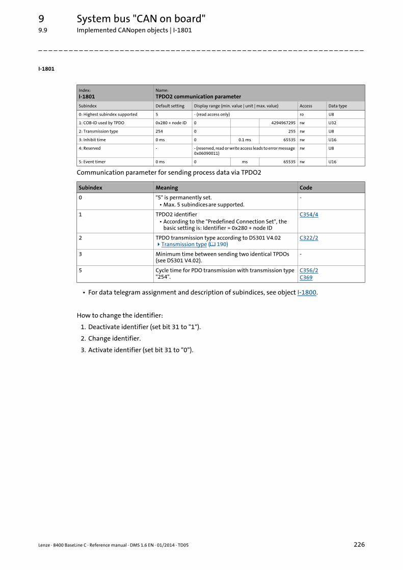
Lenze · 8400 BaseLine C · Reference manual · DMS 1.6 EN · 01/2014 · TD05 226
9 System bus "CAN on board"9.9 Implemented CANopen objects | I-1801
_ _ _ _ _ _ _ _ _ _ _ _ _ _ _ _ _ _ _ _ _ _ _ _ _ _ _ _ _ _ _ _ _ _ _ _ _ _ _ _ _ _ _ _ _ _ _ _ _ _ _ _ _ _ _ _ _ _ _ _ _ _ _ _
I-1801
Communication parameter for sending process data via TPDO2
• For data telegram assignment and description of subindices, see object I-1800.
How to change the identifier:
1. Deactivate identifier (set bit 31 to "1").
2. Change identifier.
3. Activate identifier (set bit 31 to "0").
Index:
I-1801Name:
TPDO2 communication parameter
Subindex Default setting Display range (min. value | unit | max. value) Access Data type
0: Highest subindex supported 5 - (read access only) ro U8
1: COB-ID used by TPDO 0x280 + node ID 0 4294967295 rw U32
2: Transmission type 254 0 255 rw U8
3: Inhibit time 0 ms 0 0.1 ms 65535 rw U16
4: Reserved - - (reserved, read or write access leads to error message 0x06090011)
rw U8
5: Event timer 0 ms 0 ms 65535 rw U16
Subindex Meaning Code
0 "5" is permanently set.• Max. 5 subindicesare supported.
-
1 TPDO2 identifier• According to the "Predefined Connection Set", the
basic setting is: Identifier = 0x280 + node ID
C354/4
2 TPDO transmission type according to DS301 V4.02 Transmission type ( 190)
C322/2
3 Minimum time between sending two identical TPDOs (see DS301 V4.02).
-
5 Cycle time for PDO transmission with transmission type "254".
C356/2C369
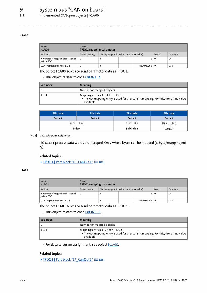
9 System bus "CAN on board"9.9 Implemented CANopen objects | I-1A00
227 Lenze · 8400 BaseLine C · Reference manual · DMS 1.6 EN · 01/2014 · TD05
_ _ _ _ _ _ _ _ _ _ _ _ _ _ _ _ _ _ _ _ _ _ _ _ _ _ _ _ _ _ _ _ _ _ _ _ _ _ _ _ _ _ _ _ _ _ _ _ _ _ _ _ _ _ _ _ _ _ _ _ _ _ _ _
I-1A00
The object I-1A00 serves to send parameter data as TPDO1.
• This object relates to code C868/1...4.
[9-24] Data telegram assignment
IEC 61131 process data words are mapped. Only whole bytes can be mapped (1-byte/mapping ent-ry).
Related topics:
TPDO1 | Port block "LP_CanOut1" ( 187)
I-1A01
The object I-1A01 serves to send parameter data as TPDO2.
• This object relates to code C868/5...8.
• For data telegram assignment, see object I-1A00.
Related topics:
TPDO2 | Port block "LP_CanOut2" ( 188)
Index:
I-1A00Name:
TPDO1 mapping parameter
Subindex Default setting Display range (min. value | unit | max. value) Access Data type
0: Number of mapped application ob-jects in PDO
0 0 8 rw U8
1 ... 4: Application object 1 ... 4 0 0 4294967295 rw U32
Subindex Meaning
0 Number of mapped objects
1 ... 4 Mapping entries 1 ... 4 for TPDO1• The 4th mapping entry is used for the statistic mapping. For this, there is no value
available.
8th byte 7th byte 6th byte 5th byte
Data 4 Data 3 Data 2 Data 1
Bit 31 ... bit 16 Bit 15 ... bit 8 Bit 7 ... bit 0
Index Subindex Length
Index:
I-1A01Name:
TPDO2 mapping parameter
Subindex Default setting Display range (min. value | unit | max. value) Access Data type
0: Number of mapped application ob-jects in PDO
0 0 8 rw U8
1 ... 4: Application object 1 ... 4 0 0 4294967295 rw U32
Subindex Meaning
0 Number of mapped objects
1 ... 4 Mapping entries 1 ... 4 for TPDO2• The 4th mapping entry is used for the statistic mapping. For this, there is no value
available.

10 Parameter reference
228 Lenze · 8400 BaseLine C · Reference manual · DMS 1.6 EN · 01/2014 · TD05
_ _ _ _ _ _ _ _ _ _ _ _ _ _ _ _ _ _ _ _ _ _ _ _ _ _ _ _ _ _ _ _ _ _ _ _ _ _ _ _ _ _ _ _ _ _ _ _ _ _ _ _ _ _ _ _ _ _ _ _ _ _ _ _
10 Parameter reference
This chapter describes all parameters which can be used for parameterising and monitoring thecontroller.
Parameters which are only available in the controller from a certain software version onwards aremarked with a corresponding note in the parameter description ("from version xx.xx.xx").
The parameter descriptions are based on the software version V03.04.00
Tip!
For quick reference of a parameter with a certain name, simply use the index of the online documentation. The index always contains the corresponding code in parentheses after the name.
General information on parameter setting can be found in the chapter entitled "Introduction: Parameterising the controller". ( 12)
For general information on how to read and change parameters, please see the online do-cumentation for the »Engineer«.
Lenze · 8400 BaseLine C · Reference manual · DMS 1.6 EN · 01/2014 · TD05 229
10 Parameter reference10.1 Structure of the parameter descriptions
_ _ _ _ _ _ _ _ _ _ _ _ _ _ _ _ _ _ _ _ _ _ _ _ _ _ _ _ _ _ _ _ _ _ _ _ _ _ _ _ _ _ _ _ _ _ _ _ _ _ _ _ _ _ _ _ _ _ _ _ _ _ _ _
10.1 Structure of the parameter descriptions
Each parameter is described in the Parameter list in the form of a table which consists of the follo-wing three areas:
Table header
The table header contains the following general information:
• Parameter number (Cxxxxx)
• Parameter name (display text in the »Engineer» and keypad)
• Data type
• Parameter index in decimal and hexadecimal notation for access via a fieldbus (e.g. CAN system bus).
Tip!
The parameter index is calculated as follows:• Index [dec] = 24575 - code• Index [hex] = 0x5FFF - code
Example for code C00005:• Index [dec] = 24575 - 5 = 24570• Index [hex] = 0x5FFF - 0x{5} = 0x5FFA
Table contents
The table contains further general explanations & notes on the parameter and the possible settings,which are represented in different ways depending on the parameter type:
• Parameters with read-only access
• Parameters with write access
Table footer
The table footer contains the Parameter attributes.
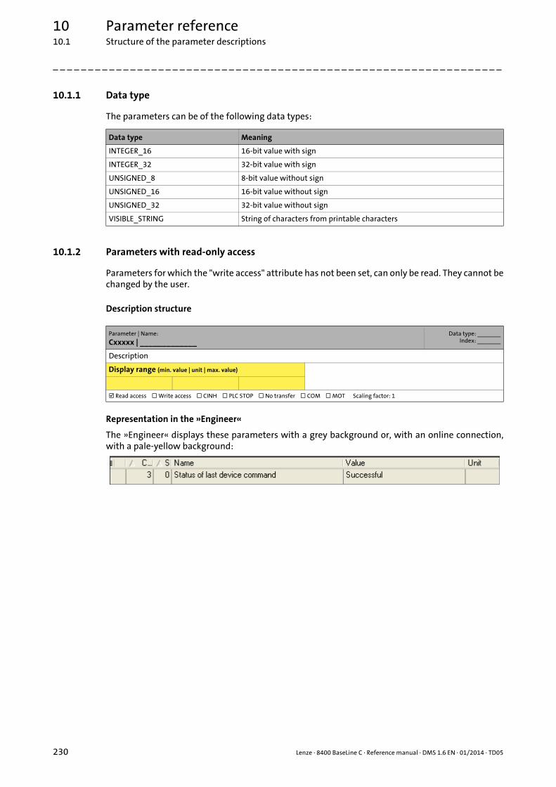
10 Parameter reference10.1 Structure of the parameter descriptions
230 Lenze · 8400 BaseLine C · Reference manual · DMS 1.6 EN · 01/2014 · TD05
_ _ _ _ _ _ _ _ _ _ _ _ _ _ _ _ _ _ _ _ _ _ _ _ _ _ _ _ _ _ _ _ _ _ _ _ _ _ _ _ _ _ _ _ _ _ _ _ _ _ _ _ _ _ _ _ _ _ _ _ _ _ _ _
10.1.1 Data type
The parameters can be of the following data types:
10.1.2 Parameters with read-only access
Parameters for which the "write access" attribute has not been set, can only be read. They cannot bechanged by the user.
Description structure
Representation in the »Engineer«
The »Engineer« displays these parameters with a grey background or, with an online connection,with a pale-yellow background:
Data type Meaning
INTEGER_16 16-bit value with sign
INTEGER_32 32-bit value with sign
UNSIGNED_8 8-bit value without sign
UNSIGNED_16 16-bit value without sign
UNSIGNED_32 32-bit value without sign
VISIBLE_STRING String of characters from printable characters
Parameter | Name:
Cxxxxx | _____________Data type: _______
Index: _______
Description
Display range (min. value | unit | max. value)
Read access Write access CINH PLC STOP No transfer COM MOT Scaling factor: 1

Lenze · 8400 BaseLine C · Reference manual · DMS 1.6 EN · 01/2014 · TD05 231
10 Parameter reference10.1 Structure of the parameter descriptions
_ _ _ _ _ _ _ _ _ _ _ _ _ _ _ _ _ _ _ _ _ _ _ _ _ _ _ _ _ _ _ _ _ _ _ _ _ _ _ _ _ _ _ _ _ _ _ _ _ _ _ _ _ _ _ _ _ _ _ _ _ _ _ _
10.1.3 Parameters with write access
Only parameters with a check mark () in front of the "write access" attribute can be changed bythe user. The Lenze setting for these parameters is printed in bold.
• The settings can either be selected from a selection list or the values can be entered directly.
• Values outside the valid setting range are represented in red in the »Engineer«.
10.1.3.1 Parameters with setting range
Description structure
Parameter setting in the »Engineer«
In the »Engineer«, parameters are set by entering the desired value into the input field:
10.1.3.2 Parameters with selection list
Description structure
Parameter | Name:
Cxxxxx | _____________Data type: _______
Index: _______
Description
Setting range (min. value | unit | max. value) Lenze setting
Read access Write access CINH PLC STOP No transfer COM MOT Scaling factor: 1
Parameter | Name:
Cxxxxx | _____________Data type: _______
Index: _______
Description
Selection list (Lenze setting printed in bold)
1
2
3
Read access Write access CINH PLC STOP No transfer COM MOT Scaling factor: 1
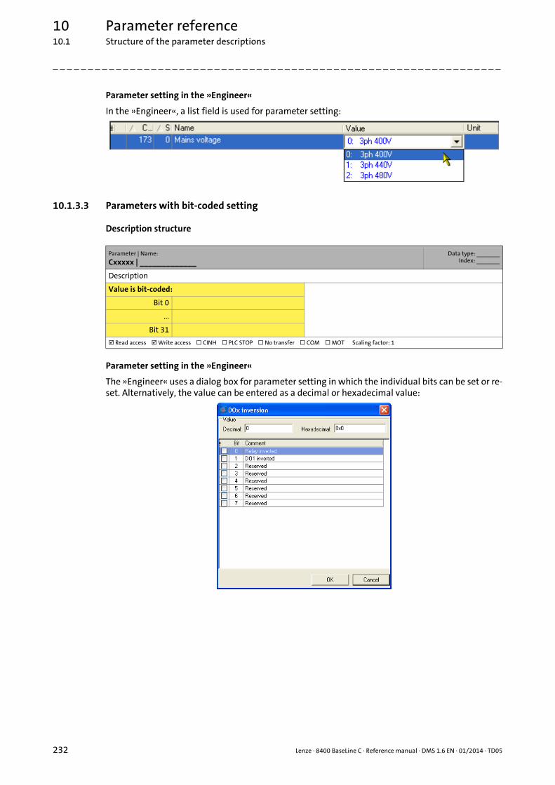
10 Parameter reference10.1 Structure of the parameter descriptions
232 Lenze · 8400 BaseLine C · Reference manual · DMS 1.6 EN · 01/2014 · TD05
_ _ _ _ _ _ _ _ _ _ _ _ _ _ _ _ _ _ _ _ _ _ _ _ _ _ _ _ _ _ _ _ _ _ _ _ _ _ _ _ _ _ _ _ _ _ _ _ _ _ _ _ _ _ _ _ _ _ _ _ _ _ _ _
Parameter setting in the »Engineer«
In the »Engineer«, a list field is used for parameter setting:
10.1.3.3 Parameters with bit-coded setting
Description structure
Parameter setting in the »Engineer«
The »Engineer« uses a dialog box for parameter setting in which the individual bits can be set or re-set. Alternatively, the value can be entered as a decimal or hexadecimal value:
Parameter | Name:
Cxxxxx | _____________Data type: _______
Index: _______
Description
Value is bit-coded:
Bit 0
...
Bit 31
Read access Write access CINH PLC STOP No transfer COM MOT Scaling factor: 1

Lenze · 8400 BaseLine C · Reference manual · DMS 1.6 EN · 01/2014 · TD05 233
10 Parameter reference10.1 Structure of the parameter descriptions
_ _ _ _ _ _ _ _ _ _ _ _ _ _ _ _ _ _ _ _ _ _ _ _ _ _ _ _ _ _ _ _ _ _ _ _ _ _ _ _ _ _ _ _ _ _ _ _ _ _ _ _ _ _ _ _ _ _ _ _ _ _ _ _
10.1.3.4 Parameters with subcodes
Description structure
Parameter setting in the »Engineer«
The »Engineer« parameter list displays each subcode individually. The parameters are set as descri-bed in the previous chapters.
Parameter | Name:
Cxxxxx | _____________Data type: _______
Index: _______
Description
Setting range (min. value | unit | max. value)
Subcodes Lenze setting
Cxxxxx/1
Cxxxxx/2
Cxxxxx/3
Read access Write access CINH PLC STOP No transfer COM MOT Scaling factor: 1
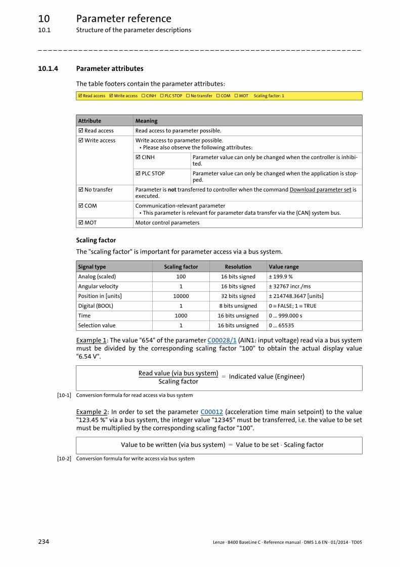
10 Parameter reference10.1 Structure of the parameter descriptions
234 Lenze · 8400 BaseLine C · Reference manual · DMS 1.6 EN · 01/2014 · TD05
_ _ _ _ _ _ _ _ _ _ _ _ _ _ _ _ _ _ _ _ _ _ _ _ _ _ _ _ _ _ _ _ _ _ _ _ _ _ _ _ _ _ _ _ _ _ _ _ _ _ _ _ _ _ _ _ _ _ _ _ _ _ _ _
10.1.4 Parameter attributes
The table footers contain the parameter attributes:
Scaling factor
The "scaling factor" is important for parameter access via a bus system.
Example 1: The value "654" of the parameter C00028/1 (AIN1: input voltage) read via a bus systemmust be divided by the corresponding scaling factor "100" to obtain the actual display value"6.54 V".
[10-1] Conversion formula for read access via bus system
Example 2: In order to set the parameter C00012 (acceleration time main setpoint) to the value"123.45 %" via a bus system, the integer value "12345" must be transferred, i.e. the value to be setmust be multiplied by the corresponding scaling factor "100".
[10-2] Conversion formula for write access via bus system
Read access Write access CINH PLC STOP No transfer COM MOT Scaling factor: 1
Attribute Meaning
Read access Read access to parameter possible.
Write access Write access to parameter possible.• Please also observe the following attributes:
CINH Parameter value can only be changed when the controller is inhibi-ted.
PLC STOP Parameter value can only be changed when the application is stop-ped.
No transfer Parameter is not transferred to controller when the command Download parameter set is executed.
COM Communication-relevant parameter• This parameter is relevant for parameter data transfer via the (CAN) system bus.
MOT Motor control parameters
Signal type Scaling factor Resolution Value range
Analog (scaled) 100 16 bits signed ± 199.9 %
Angular velocity 1 16 bits signed ± 32767 incr./ms
Position in [units] 10000 32 bits signed ± 214748.3647 [units]
Digital (BOOL) 1 8 bits unsigned 0 ≡ FALSE; 1 ≡ TRUE
Time 1000 16 bits unsigned 0 ... 999.000 s
Selection value 1 16 bits unsigned 0 ... 65535
Read value (via bus system)Scaling factor
----------------------------------------------------------------------- Indicated value (Engineer)=
Value to be written (via bus system) Value to be set Scaling factor⋅=
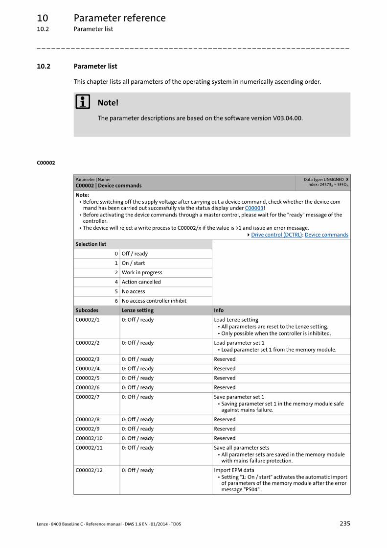
Lenze · 8400 BaseLine C · Reference manual · DMS 1.6 EN · 01/2014 · TD05 235
10 Parameter reference10.2 Parameter list
_ _ _ _ _ _ _ _ _ _ _ _ _ _ _ _ _ _ _ _ _ _ _ _ _ _ _ _ _ _ _ _ _ _ _ _ _ _ _ _ _ _ _ _ _ _ _ _ _ _ _ _ _ _ _ _ _ _ _ _ _ _ _ _
10.2 Parameter list
This chapter lists all parameters of the operating system in numerically ascending order.
C00002
Note!
The parameter descriptions are based on the software version V03.04.00.
Parameter | Name:
C00002 | Device commandsData type: UNSIGNED_8
Index: 24573d = 5FFDh
Note:• Before switching off the supply voltage after carrying out a device command, check whether the device com-
mand has been carried out successfully via the status display under C00003!• Before activating the device commands through a master control, please wait for the "ready" message of the
controller.• The device will reject a write process to C00002/x if the value is >1 and issue an error message.
Drive control (DCTRL): Device commands
Selection list
0 Off / ready
1 On / start
2 Work in progress
4 Action cancelled
5 No access
6 No access controller inhibit
Subcodes Lenze setting Info
C00002/1 0: Off / ready Load Lenze setting• All parameters are reset to the Lenze setting.• Only possible when the controller is inhibited.
C00002/2 0: Off / ready Load parameter set 1• Load parameter set 1 from the memory module.
C00002/3 0: Off / ready Reserved
C00002/4 0: Off / ready Reserved
C00002/5 0: Off / ready Reserved
C00002/6 0: Off / ready Reserved
C00002/7 0: Off / ready Save parameter set 1• Saving parameter set 1 in the memory module safe
against mains failure.
C00002/8 0: Off / ready Reserved
C00002/9 0: Off / ready Reserved
C00002/10 0: Off / ready Reserved
C00002/11 0: Off / ready Save all parameter sets• All parameter sets are saved in the memory module
with mains failure protection.
C00002/12 0: Off / ready Import EPM data• Setting "1: On / start" activates the automatic import
of parameters of the memory module after the error message "PS04".

10 Parameter reference10.2 Parameter list
236 Lenze · 8400 BaseLine C · Reference manual · DMS 1.6 EN · 01/2014 · TD05
_ _ _ _ _ _ _ _ _ _ _ _ _ _ _ _ _ _ _ _ _ _ _ _ _ _ _ _ _ _ _ _ _ _ _ _ _ _ _ _ _ _ _ _ _ _ _ _ _ _ _ _ _ _ _ _ _ _ _ _ _ _ _ _
C00002/13 0: Off / ready Reserved
C00002/14 0: Off / ready Reserved
C00002/15 0: Off / ready Reserved
C00002/16 1: On / start Enable controller"1" ≡ Enable controller"0" ≡ Inhibit controller
C00002/17 0: Off / ready Activate quick stop"1" ≡ Activate quick stop"0" ≡ Deactivate quick stop
C00002/18 0: Off / ready Reserved
C00002/19 0: Off / ready Reset error• After resetting the current error, further errors may be
pending which must be reset as well.• Details of the currently pending error are displayed in
C00166.
C00002/20 0: Off / ready Reserved
C00002/21 0: Off / ready Delete logbook• All entries in the controller logbook will be deleted.• In the logbook, information on the error history is sa-
ved.
C00002/22 0: Off / ready Reserved
C00002/23 0: Off / ready Identify motor parameters• This device command serves to carry out an auto-
matic identification of the motor parameters.• The device command is only executed when the con-
troller is in the "SwitchedOn" state.• In order to identify the motor parameters, the cont-
roller must be enabled after this device command.Identifying motor parameters automatically
C00002/24 0: Off / ready Reserved
C00002/25 0: Off / ready Reserved
C00002/26 0: Off / ready CAN reset node• Reinitialise "CAN on board" interface.• Required when changing the baud rate, node address,
or identifiers.System bus "CAN on board"
C00002/27 0: Off / ready Reserved
C00002/28 0: Off / ready Reserved
C00002/29 0: Off / ready Reserved
C00002/30 0: Off / ready Reserved
C00002/31 0: Off / ready Reserved
C00002/32 0: Off / ready Reserved
Read access Write access CINH PLC STOP No transfer COM MOT Scaling factor: 1
Parameter | Name:
C00002 | Device commandsData type: UNSIGNED_8
Index: 24573d = 5FFDh

10 Parameter reference10.2 Parameter list | C00003
237 Lenze · 8400 BaseLine C · Reference manual · DMS 1.6 EN · 01/2014 · TD05
_ _ _ _ _ _ _ _ _ _ _ _ _ _ _ _ _ _ _ _ _ _ _ _ _ _ _ _ _ _ _ _ _ _ _ _ _ _ _ _ _ _ _ _ _ _ _ _ _ _ _ _ _ _ _ _ _ _ _ _ _ _ _ _
C00003
C00006
Parameter | Name:
C00003 | Status of last device commandData type: UNSIGNED_8
Index: 24572d = 5FFCh
Status of the device command carried out last (C00002).
Note:Before switching off the supply voltage after carrying out a device command, check whether the device command has been carried out successfully via the status display!
Drive control (DCTRL): Device commands
Selection list (read only) Info
0 Successful Device command has been carried out successfully.
1 Command unknown Device command is implausible or not known in the sys-tem.
2 No access Access for requested device command is not approved.
3 Time-out Device command could not be processed in the defined time (time-out).
Read access Write access CINH PLC STOP No transfer COM MOT Scaling factor: 1
Parameter | Name:
C00006 | Motor controlData type: UNSIGNED_8
Index: 24569d = 5FF9h
Selection of the motor control modeMotor control (MCTRL): Select control mode
Selection list (Lenze setting printed in bold) Info
4 SLVC: Vector control This control type is used for sensorless vector control of an asynchronous motor.
• The control type requires motor parameters to be set as exactly as possible!
Sensorless vector control
6 VFCplus: V/f linear This control type is used for the speed control of an asyn-chronous motor via a linear V/f characteristic and is the simplest control type.
• For setting the V/f characteristic, only the rated fre-quency (C00089) and the rated voltage (C00090) of the motor have to be entered.
V/f characteristic control
8 VFCplus: V/f quadr This control type is used for speed control of an asynchro-nous motor via a square-law V/f characteristic.
• For setting the V/f characteristic, only the rated fre-quency (C00089) and the rated voltage (C00090) of the motor have to be entered.
V/f characteristic control
Read access Write access CINH PLC STOP No transfer COM MOT Scaling factor: 1
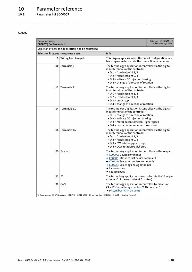
Lenze · 8400 BaseLine C · Reference manual · DMS 1.6 EN · 01/2014 · TD05 238
10 Parameter reference10.2 Parameter list | C00007
_ _ _ _ _ _ _ _ _ _ _ _ _ _ _ _ _ _ _ _ _ _ _ _ _ _ _ _ _ _ _ _ _ _ _ _ _ _ _ _ _ _ _ _ _ _ _ _ _ _ _ _ _ _ _ _ _ _ _ _ _ _ _ _
C00007
Parameter | Name:
C00007 | Control modeData type: UNSIGNED_16
Index: 24568d = 5FF8h
Selection of how the application is to be controlled.
Selection list (Lenze setting printed in bold) Info
0 Wiring has changed This display appears when the preset configuration has been reparameterised via the connection parameters.
10 Terminals 0 The technology application is controlled via the digital input terminals of the controller:
• DI1 = fixed setpoint 1/3• DI2 = fixed setpoint 2/3• DI3 = activate DC injection braking• DI4 = change of direction of rotation
12 Terminals 2 The technology application is controlled via the digital input terminals of the controller:
• DI1 = fixed setpoint 1/3• DI2 = fixed setpoint 2/3• DI3 = quick stop• DI4 = change of direction of rotation
14 Terminals 11 The technology application is controlled via the digital input terminals of the controller:
• DI1 = change of direction of rotation• DI2 = activate DC injection braking• DI3 = motor potentiometer: Higher speed• DI4 = motor potentiometer: Lower speed
16 Terminals 16 The technology application is controlled via the digital input terminals of the controller:
• DI1 = fixed setpoint 1/3• DI2 = fixed setpoint 2/3• DI3 = CW rotation/quick stop• DI4 = CCW rotation/quick stop
20 Keypad The technology application is controlled via the keypad: C00002: Device commands C00003: Status of last device command C00727: Executing control commands C00728: Selecting analog setpoints Increase speed Reduce speed
21 PC The technology application is controlled via the "Free pa-rameters" of the controller (PC control).
30 CAN The technology application is controlled by means of CAN-PDOs via the system bus "CAN on board".System bus "CAN on board"
Read access Write access CINH PLC STOP No transfer COM MOT Scaling factor: 1

10 Parameter reference10.2 Parameter list | C00010
239 Lenze · 8400 BaseLine C · Reference manual · DMS 1.6 EN · 01/2014 · TD05
_ _ _ _ _ _ _ _ _ _ _ _ _ _ _ _ _ _ _ _ _ _ _ _ _ _ _ _ _ _ _ _ _ _ _ _ _ _ _ _ _ _ _ _ _ _ _ _ _ _ _ _ _ _ _ _ _ _ _ _ _ _ _ _
C00010
C00011
C00012
C00013
Parameter | Name:
C00010 | Minimum analog setpointData type: INTEGER_16
Index: 24565d = 5FF5h
As of version 03.00.00Lower limit for analog input
Analog terminals
Setting range (min. value | unit | max. value)
0.0 % 100.0
Subcodes Lenze setting Info
C00010/1 0.0 % Min. analog setpoint
Read access Write access CINH PLC STOP No transfer COM MOT Scaling factor: 100
Parameter | Name:
C00011 | Appl.: Reference speedData type: UNSIGNED_16
Index: 24564d = 5FF4h
Setting the reference speed• In the controller, all speed-related signals are processed to one reference variable in percent.• Set a reference speed here that corresponds to 100 %.• The frequency of the set reference speed is displayed in C00059.
Note:This is not a maximum limitation!All values in percent in the controller may be in the range of 0 ... 199.99 %.
Setting range (min. value | unit | max. value) Lenze setting
50 rpm 9999 1500 rpm
Read access Write access CINH PLC STOP No transfer COM MOT Scaling factor: 1
Parameter | Name:
C00012 | Acceleration time main setpointData type: UNSIGNED_32
Index: 24563d = 5FF3h
FB L_NSet_1: Acceleration time of the ramp generator for the main speed setpoint
Setting range (min. value | unit | max. value) Lenze setting
0.0 s 999.9 2.0 s
Read access Write access CINH PLC STOP No transfer COM MOT Scaling factor: 1000
Parameter | Name:
C00013 | Deceleration time main setpointData type: UNSIGNED_32
Index: 24562d = 5FF2h
FB L_NSet_1: Deceleration time of the ramp generator for the main speed setpoint
Setting range (min. value | unit | max. value) Lenze setting
0.0 s 999.9 2.0 s
Read access Write access CINH PLC STOP No transfer COM MOT Scaling factor: 1000
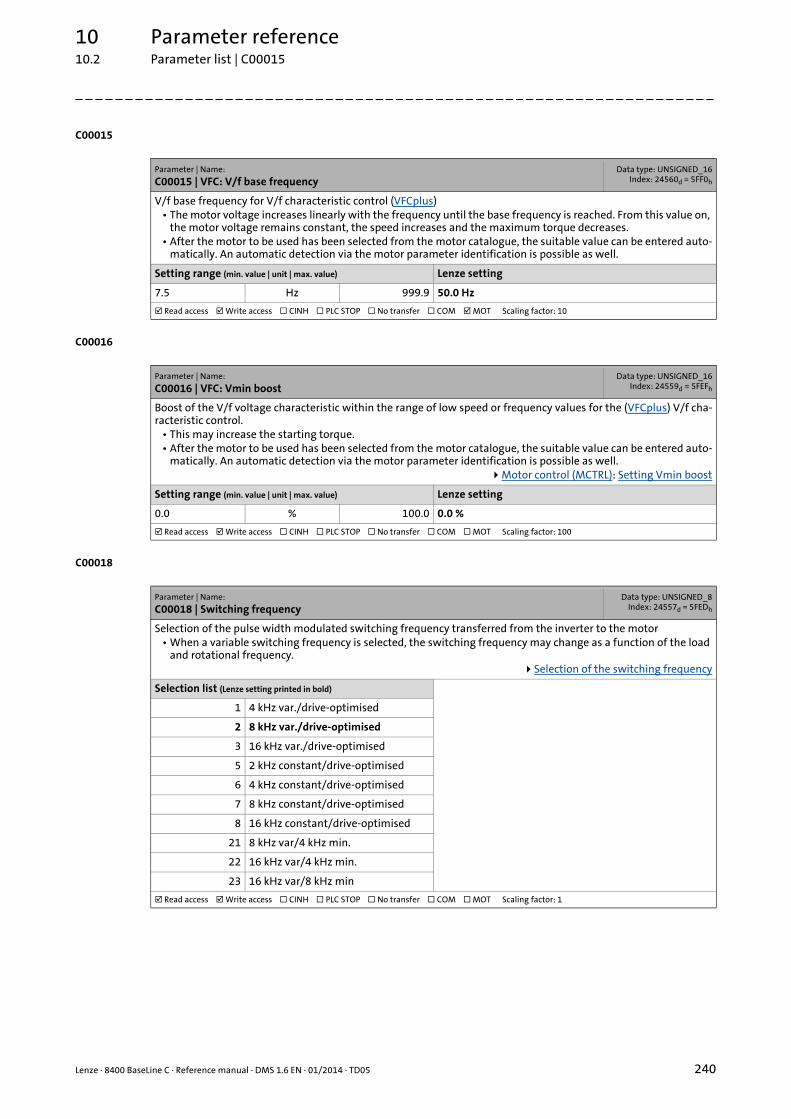
Lenze · 8400 BaseLine C · Reference manual · DMS 1.6 EN · 01/2014 · TD05 240
10 Parameter reference10.2 Parameter list | C00015
_ _ _ _ _ _ _ _ _ _ _ _ _ _ _ _ _ _ _ _ _ _ _ _ _ _ _ _ _ _ _ _ _ _ _ _ _ _ _ _ _ _ _ _ _ _ _ _ _ _ _ _ _ _ _ _ _ _ _ _ _ _ _ _
C00015
C00016
C00018
Parameter | Name:
C00015 | VFC: V/f base frequencyData type: UNSIGNED_16
Index: 24560d = 5FF0h
V/f base frequency for V/f characteristic control (VFCplus)• The motor voltage increases linearly with the frequency until the base frequency is reached. From this value on,
the motor voltage remains constant, the speed increases and the maximum torque decreases.• After the motor to be used has been selected from the motor catalogue, the suitable value can be entered auto-
matically. An automatic detection via the motor parameter identification is possible as well.
Setting range (min. value | unit | max. value) Lenze setting
7.5 Hz 999.9 50.0 Hz
Read access Write access CINH PLC STOP No transfer COM MOT Scaling factor: 10
Parameter | Name:
C00016 | VFC: Vmin boostData type: UNSIGNED_16
Index: 24559d = 5FEFh
Boost of the V/f voltage characteristic within the range of low speed or frequency values for the (VFCplus) V/f cha-racteristic control.
• This may increase the starting torque.• After the motor to be used has been selected from the motor catalogue, the suitable value can be entered auto-
matically. An automatic detection via the motor parameter identification is possible as well.Motor control (MCTRL): Setting Vmin boost
Setting range (min. value | unit | max. value) Lenze setting
0.0 % 100.0 0.0 %
Read access Write access CINH PLC STOP No transfer COM MOT Scaling factor: 100
Parameter | Name:
C00018 | Switching frequencyData type: UNSIGNED_8
Index: 24557d = 5FEDh
Selection of the pulse width modulated switching frequency transferred from the inverter to the motor• When a variable switching frequency is selected, the switching frequency may change as a function of the load
and rotational frequency.Selection of the switching frequency
Selection list (Lenze setting printed in bold)
1 4 kHz var./drive-optimised
2 8 kHz var./drive-optimised
3 16 kHz var./drive-optimised
5 2 kHz constant/drive-optimised
6 4 kHz constant/drive-optimised
7 8 kHz constant/drive-optimised
8 16 kHz constant/drive-optimised
21 8 kHz var/4 kHz min.
22 16 kHz var/4 kHz min.
23 16 kHz var/8 kHz min
Read access Write access CINH PLC STOP No transfer COM MOT Scaling factor: 1

10 Parameter reference10.2 Parameter list | C00019
241 Lenze · 8400 BaseLine C · Reference manual · DMS 1.6 EN · 01/2014 · TD05
_ _ _ _ _ _ _ _ _ _ _ _ _ _ _ _ _ _ _ _ _ _ _ _ _ _ _ _ _ _ _ _ _ _ _ _ _ _ _ _ _ _ _ _ _ _ _ _ _ _ _ _ _ _ _ _ _ _ _ _ _ _ _ _
C00019
C00021
C00022
C00023
Parameter | Name:
C00019 | Auto DCB: ThresholdData type: UNSIGNED_16
Index: 24556d = 5FECh
Setpoint speed threshold for automatic DC injection braking• For speed setpoints with values below the thresholds a DC current is injected or the motor is not supplied with
current, depending on the setting.DC injection braking
Setting range (min. value | unit | max. value) Lenze setting
0 rpm 9999 3 rpm
Read access Write access CINH PLC STOP No transfer COM MOT Scaling factor: 1
Parameter | Name:
C00021 | Slip comp.Data type: INTEGER_16Index: 24554d = 5FEAh
Slip compensation for V/f characteristic control (VFCplus) and sensorless vector control (SLVC)• An increase of the slip compensation causes a greater frequency and voltage increase when the machine is loa-
ded.• After the motor to be used has been selected from the motor catalogue, the suitable value can be entered auto-
matically. An automatic detection via the motor parameter identification is possible as well.Motor control (MCTRL): Optimising the operational performance by slip compensation
Setting range (min. value | unit | max. value) Lenze setting
-50.00 % 50.00 0.00 %
Read access Write access CINH PLC STOP No transfer COM MOT Scaling factor: 100
Parameter | Name:
C00022 | Imax in motor modeData type: UNSIGNED_16
Index: 24553d = 5FE9h
Maximum current in motor mode for all motor control modes
Setting range (min. value | unit | max. value) Lenze setting
0.00 A 99.99 47.00 A
Read access Write access CINH PLC STOP No transfer COM MOT Scaling factor: 100
Parameter | Name:
C00023 | Imax in generator modeData type: INTEGER_16
Index: 24552d = 5FE8h
Maximum current in generator mode for all motor control modes• 100 % ≡ Imax in motor mode (C00022)
Setting range (min. value | unit | max. value) Lenze setting
0.0 % 100.0 100.0 %
Read access Write access CINH PLC STOP No transfer COM MOT Scaling factor: 100

Lenze · 8400 BaseLine C · Reference manual · DMS 1.6 EN · 01/2014 · TD05 242
10 Parameter reference10.2 Parameter list | C00024
_ _ _ _ _ _ _ _ _ _ _ _ _ _ _ _ _ _ _ _ _ _ _ _ _ _ _ _ _ _ _ _ _ _ _ _ _ _ _ _ _ _ _ _ _ _ _ _ _ _ _ _ _ _ _ _ _ _ _ _ _ _ _ _
C00024
C00026
C00027
C00028
Parameter | Name:
C00024 | Comparison value N_ActData type: INTEGER_16
Index: 24551d = 5FE7h
Threshold for the actual speed comparison• This parameter serves to set a threshold that is compared with the actual speed value.• When the value falls below this threshold, the bNactCompare output of the SB LS_DriveInterface switches to
TRUE.• Switching hysteresis = +1 %
Setting range (min. value | unit | max. value) Lenze setting
0.0 % 199.9 0.0 %
Read access Write access CINH PLC STOP No transfer COM MOT Scaling factor: 100
Parameter | Name:
C00026 | AINx: OffsetData type: INTEGER_16
Index: 24549d = 5FE5h
Offset for analog inputAnalog terminals
Setting range (min. value | unit | max. value)
-199.9 % 199.9
Subcodes Lenze setting Info
C00026/1 0.0 % AIN1: Offset
Read access Write access CINH PLC STOP No transfer COM MOT Scaling factor: 100
Parameter | Name:
C00027 | AINx: GainData type: INTEGER_32
Index: 24548d = 5FE4h
Gain for analog inputAnalog terminals
Setting range (min. value | unit | max. value)
-199.9 % 199.9
Subcodes Lenze setting Info
C00027/1 100.0 % AIN1: Gain
Read access Write access CINH PLC STOP No transfer COM MOT Scaling factor: 100
Parameter | Name:
C00028 | AINx: Input voltageData type: INTEGER_16
Index: 24547d = 5FE3h
Display of the input voltage at the analog inputAnalog terminals
Display range (min. value | unit | max. value)
-10.0 V 10.0
Subcodes Info
C00028/1 AIN1: Input voltage
Read access Write access CINH PLC STOP No transfer COM MOT Scaling factor: 100

10 Parameter reference10.2 Parameter list | C00029
243 Lenze · 8400 BaseLine C · Reference manual · DMS 1.6 EN · 01/2014 · TD05
_ _ _ _ _ _ _ _ _ _ _ _ _ _ _ _ _ _ _ _ _ _ _ _ _ _ _ _ _ _ _ _ _ _ _ _ _ _ _ _ _ _ _ _ _ _ _ _ _ _ _ _ _ _ _ _ _ _ _ _ _ _ _ _
C00029
C00033
C00034
Parameter | Name:
C00029 | AINx: Input currentData type: INTEGER_16
Index: 24546d = 5FE2h
Display of the input current at the analog input• When the analog input has been configured for current measurement (C00034/1 = 1 or 2).• When C00034/1 is set = 2 (4 ... 20 mA), 0 ... 16 mA is displayed.
Analog terminals
Display range (min. value | unit | max. value)
0.0 mA 20.0
Subcodes Info
C00029/1 AIN1: Input current
Read access Write access CINH PLC STOP No transfer COM MOT Scaling factor: 100
Parameter | Name:
C00033 | AINx: Output valueData type: INTEGER_16Index: 24542d = 5FDEh
Display of the output value in percent of the analog input amplifier• 100 % ≡ 16384 ≡ +10 V / +20 mA
Analog terminals
Display range (min. value | unit | max. value)
-199.9 % 199.9
Subcodes Info
C00033/1 AIN1: Output value
Read access Write access CINH PLC STOP No transfer COM MOT Scaling factor: 100
Parameter | Name:
C00034 | AINx: ConfigurationData type: UNSIGNED_8
Index: 24541d = 5FDDh
Configuration of the analog input for current or voltage measurementAnalog terminals
Selection list Info
0 0...+10 V Input signal is voltage signal 0 V ... +10 V• 0 V ... +10 V ≡ 0 % ... +100 %
1 0...+5V With external load resistor (250 Ohms):Input signal is the current signal 0 mA ... 20 mA
• 0 mA ... 20 mA ≡ 0 % ... +100 %
2 1...+5V (4...20mA) With external load resistor (250 Ohms):Input signal is the current signal 4 mA ... 20 mA
• 4 mA ... 20 mA ≡ 0 % ... +100 %• The current loop is monitored for open circuit
(I < 4 mA) by the device.
Subcodes Lenze setting Info
C00034/1 0: 0...+10 V AIN1: Config.
Read access Write access CINH PLC STOP No transfer COM MOT Scaling factor: 1
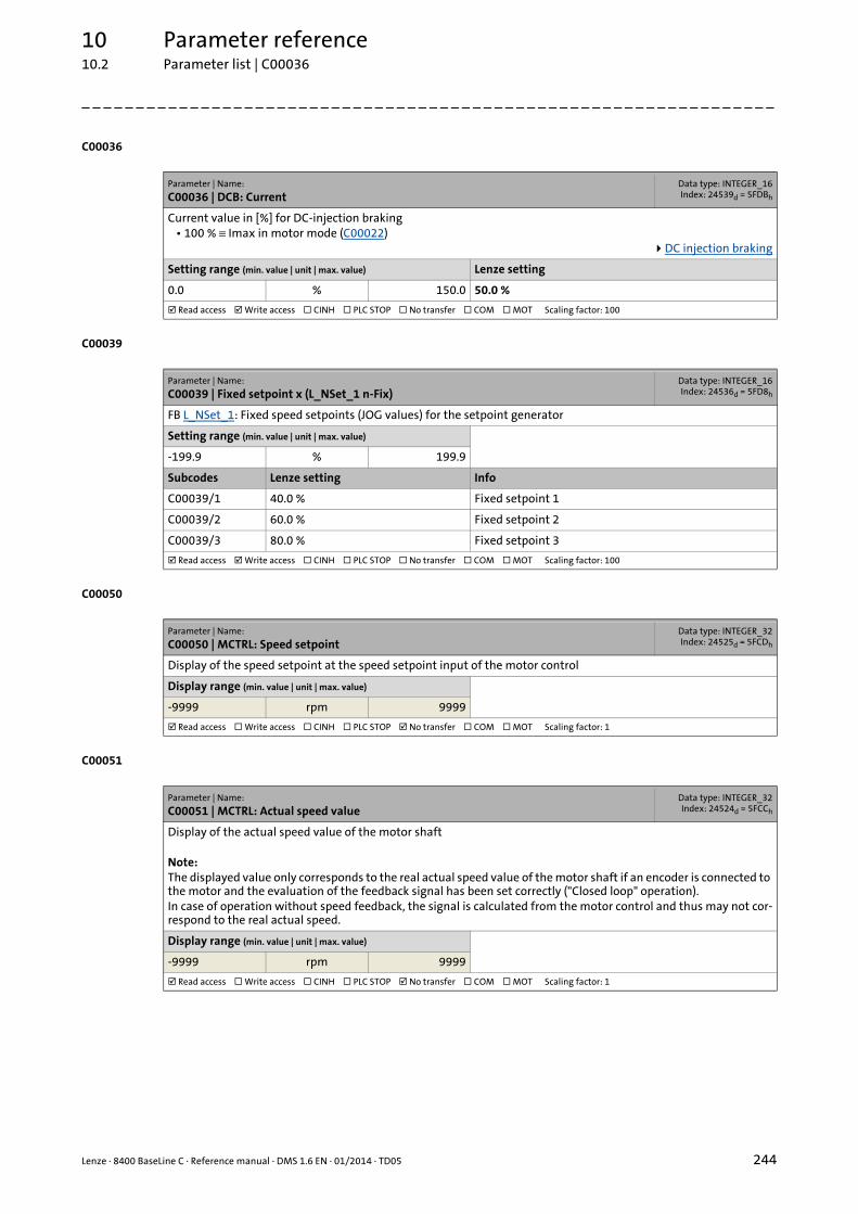
Lenze · 8400 BaseLine C · Reference manual · DMS 1.6 EN · 01/2014 · TD05 244
10 Parameter reference10.2 Parameter list | C00036
_ _ _ _ _ _ _ _ _ _ _ _ _ _ _ _ _ _ _ _ _ _ _ _ _ _ _ _ _ _ _ _ _ _ _ _ _ _ _ _ _ _ _ _ _ _ _ _ _ _ _ _ _ _ _ _ _ _ _ _ _ _ _ _
C00036
C00039
C00050
C00051
Parameter | Name:
C00036 | DCB: CurrentData type: INTEGER_16Index: 24539d = 5FDBh
Current value in [%] for DC-injection braking• 100 % ≡ Imax in motor mode (C00022)
DC injection braking
Setting range (min. value | unit | max. value) Lenze setting
0.0 % 150.0 50.0 %
Read access Write access CINH PLC STOP No transfer COM MOT Scaling factor: 100
Parameter | Name:
C00039 | Fixed setpoint x (L_NSet_1 n-Fix)Data type: INTEGER_16Index: 24536d = 5FD8h
FB L_NSet_1: Fixed speed setpoints (JOG values) for the setpoint generator
Setting range (min. value | unit | max. value)
-199.9 % 199.9
Subcodes Lenze setting Info
C00039/1 40.0 % Fixed setpoint 1
C00039/2 60.0 % Fixed setpoint 2
C00039/3 80.0 % Fixed setpoint 3
Read access Write access CINH PLC STOP No transfer COM MOT Scaling factor: 100
Parameter | Name:
C00050 | MCTRL: Speed setpointData type: INTEGER_32Index: 24525d = 5FCDh
Display of the speed setpoint at the speed setpoint input of the motor control
Display range (min. value | unit | max. value)
-9999 rpm 9999
Read access Write access CINH PLC STOP No transfer COM MOT Scaling factor: 1
Parameter | Name:
C00051 | MCTRL: Actual speed valueData type: INTEGER_32Index: 24524d = 5FCCh
Display of the actual speed value of the motor shaft
Note:The displayed value only corresponds to the real actual speed value of the motor shaft if an encoder is connected to the motor and the evaluation of the feedback signal has been set correctly ("Closed loop" operation).In case of operation without speed feedback, the signal is calculated from the motor control and thus may not cor-respond to the real actual speed.
Display range (min. value | unit | max. value)
-9999 rpm 9999
Read access Write access CINH PLC STOP No transfer COM MOT Scaling factor: 1

10 Parameter reference10.2 Parameter list | C00052
245 Lenze · 8400 BaseLine C · Reference manual · DMS 1.6 EN · 01/2014 · TD05
_ _ _ _ _ _ _ _ _ _ _ _ _ _ _ _ _ _ _ _ _ _ _ _ _ _ _ _ _ _ _ _ _ _ _ _ _ _ _ _ _ _ _ _ _ _ _ _ _ _ _ _ _ _ _ _ _ _ _ _ _ _ _ _
C00052
C00053
C00054
C00056
C00057
Parameter | Name:
C00052 | Motor voltageData type: UNSIGNED_16
Index: 24523d = 5FCBh
Display of the current motor voltage/output voltage of the inverter
Display range (min. value | unit | max. value)
0 V 1000
Read access Write access CINH PLC STOP No transfer COM MOT Scaling factor: 1
Parameter | Name:
C00053 | DC-bus voltageData type: UNSIGNED_16
Index: 24522d = 5FCAh
Display of the current DC-bus voltage
Display range (min. value | unit | max. value)
0 V 1000
Read access Write access CINH PLC STOP No transfer COM MOT Scaling factor: 1
Parameter | Name:
C00054 | Motor currentData type: UNSIGNED_16
Index: 24521d = 5FC9h
Display of the current motor current/output current of the inverter
Display range (min. value | unit | max. value)
0.00 A 300.00
Read access Write access CINH PLC STOP No transfer COM MOT Scaling factor: 100
Parameter | Name:
C00056 | TorqueData type: INTEGER_32Index: 24519d = 5FC7h
Display of the current torque
Display range (min. value | unit | max. value)
-99.00 Nm 99.00
Subcodes Info
C00056/1 Torque setpoint• Only with sensorless vector control (SLVC).
C00056/2 Actual torque• Estimated actual torque for all motor control modes.
Read access Write access CINH PLC STOP No transfer COM MOT Scaling factor: 100
Parameter | Name:
C00057 | Maximum torqueData type: UNSIGNED_32
Index: 24518d = 5FC6h
Display of the maximum torque to be generated by the motor• The maximum torque to be generated by the motor depends on various factors, e.g. on Imax in motor mode
(C00022) and the motor type used.
Display range (min. value | unit | max. value)
0.0 Nm 999.9
Read access Write access CINH PLC STOP No transfer COM MOT Scaling factor: 100
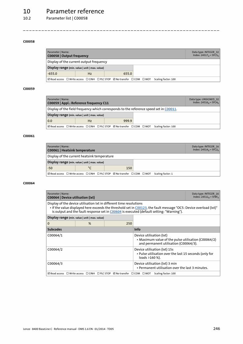
Lenze · 8400 BaseLine C · Reference manual · DMS 1.6 EN · 01/2014 · TD05 246
10 Parameter reference10.2 Parameter list | C00058
_ _ _ _ _ _ _ _ _ _ _ _ _ _ _ _ _ _ _ _ _ _ _ _ _ _ _ _ _ _ _ _ _ _ _ _ _ _ _ _ _ _ _ _ _ _ _ _ _ _ _ _ _ _ _ _ _ _ _ _ _ _ _ _
C00058
C00059
C00061
C00064
Parameter | Name:
C00058 | Output frequencyData type: INTEGER_32Index: 24517d = 5FC5h
Display of the current output frequency
Display range (min. value | unit | max. value)
-655.0 Hz 655.0
Read access Write access CINH PLC STOP No transfer COM MOT Scaling factor: 100
Parameter | Name:
C00059 | Appl.: Reference frequency C11Data type: UNSIGNED_32
Index: 24516d = 5FC4h
Display of the field frequency which corresponds to the reference speed set in C00011.
Display range (min. value | unit | max. value)
0.0 Hz 999.9
Read access Write access CINH PLC STOP No transfer COM MOT Scaling factor: 100
Parameter | Name:
C00061 | Heatsink temperatureData type: INTEGER_16Index: 24514d = 5FC2h
Display of the current heatsink temperature
Display range (min. value | unit | max. value)
-50 °C 150
Read access Write access CINH PLC STOP No transfer COM MOT Scaling factor: 1
Parameter | Name:
C00064 | Device utilisation (Ixt)Data type: INTEGER_16
Index: 24511d = 5FBFh
Display of the device utilisation Ixt in different time resolutions• If the value displayed here exceeds the threshold set in C00123, the fault message "OC5: Device overload (Ixt)"
is output and the fault response set in C00604 is executed (default setting: "Warning").
Display range (min. value | unit | max. value)
0 % 250
Subcodes Info
C00064/1 Device utilisation (Ixt)• Maximum value of the pulse utilisation (C00064/2)
and permanent utilisation (C00064/3).
C00064/2 Device utilisation (Ixt) 15s• Pulse utilisation over the last 15 seconds (only for
loads >160 %).
C00064/3 Device utilisation (Ixt) 3 min• Permanent utilisation over the last 3 minutes.
Read access Write access CINH PLC STOP No transfer COM MOT Scaling factor: 100
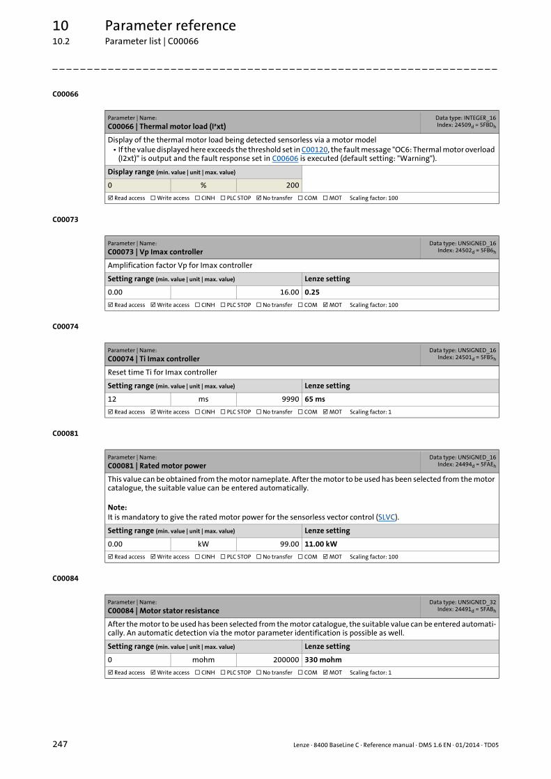
10 Parameter reference10.2 Parameter list | C00066
247 Lenze · 8400 BaseLine C · Reference manual · DMS 1.6 EN · 01/2014 · TD05
_ _ _ _ _ _ _ _ _ _ _ _ _ _ _ _ _ _ _ _ _ _ _ _ _ _ _ _ _ _ _ _ _ _ _ _ _ _ _ _ _ _ _ _ _ _ _ _ _ _ _ _ _ _ _ _ _ _ _ _ _ _ _ _
C00066
C00073
C00074
C00081
C00084
Parameter | Name:
C00066 | Thermal motor load (I²xt)Data type: INTEGER_16Index: 24509d = 5FBDh
Display of the thermal motor load being detected sensorless via a motor model• If the value displayed here exceeds the threshold set in C00120, the fault message "OC6: Thermal motor overload
(I2xt)" is output and the fault response set in C00606 is executed (default setting: "Warning").
Display range (min. value | unit | max. value)
0 % 200
Read access Write access CINH PLC STOP No transfer COM MOT Scaling factor: 100
Parameter | Name:
C00073 | Vp Imax controllerData type: UNSIGNED_16
Index: 24502d = 5FB6h
Amplification factor Vp for Imax controller
Setting range (min. value | unit | max. value) Lenze setting
0.00 16.00 0.25
Read access Write access CINH PLC STOP No transfer COM MOT Scaling factor: 100
Parameter | Name:
C00074 | Ti Imax controllerData type: UNSIGNED_16
Index: 24501d = 5FB5h
Reset time Ti for Imax controller
Setting range (min. value | unit | max. value) Lenze setting
12 ms 9990 65 ms
Read access Write access CINH PLC STOP No transfer COM MOT Scaling factor: 1
Parameter | Name:
C00081 | Rated motor powerData type: UNSIGNED_16
Index: 24494d = 5FAEh
This value can be obtained from the motor nameplate. After the motor to be used has been selected from the motor catalogue, the suitable value can be entered automatically.
Note:It is mandatory to give the rated motor power for the sensorless vector control (SLVC).
Setting range (min. value | unit | max. value) Lenze setting
0.00 kW 99.00 11.00 kW
Read access Write access CINH PLC STOP No transfer COM MOT Scaling factor: 100
Parameter | Name:
C00084 | Motor stator resistanceData type: UNSIGNED_32
Index: 24491d = 5FABh
After the motor to be used has been selected from the motor catalogue, the suitable value can be entered automati-cally. An automatic detection via the motor parameter identification is possible as well.
Setting range (min. value | unit | max. value) Lenze setting
0 mohm 200000 330 mohm
Read access Write access CINH PLC STOP No transfer COM MOT Scaling factor: 1

Lenze · 8400 BaseLine C · Reference manual · DMS 1.6 EN · 01/2014 · TD05 248
10 Parameter reference10.2 Parameter list | C00085
_ _ _ _ _ _ _ _ _ _ _ _ _ _ _ _ _ _ _ _ _ _ _ _ _ _ _ _ _ _ _ _ _ _ _ _ _ _ _ _ _ _ _ _ _ _ _ _ _ _ _ _ _ _ _ _ _ _ _ _ _ _ _ _
C00085
C00087
C00088
C00089
Parameter | Name:
C00085 | Motor stator leakage inductanceData type: UNSIGNED_16
Index: 24490d = 5FAAh
After the motor to be used has been selected from the motor catalogue, the suitable value can be entered automati-cally. An automatic detection via the motor parameter identification is possible as well.
Setting range (min. value | unit | max. value) Lenze setting
0.00 mH 650.00 0.00 mH
Read access Write access CINH PLC STOP No transfer COM MOT Scaling factor: 100
Parameter | Name:
C00087 | Rated motor speedData type: UNSIGNED_16
Index: 24488d = 5FA8h
This value can be obtained from the motor nameplate. After the motor to be used has been selected from the motor catalogue, the suitable value can be entered automatically.
Note:It is mandatory to give the rated motor speed for the sensorless vector control (SLVC).
Setting range (min. value | unit | max. value) Lenze setting
50 rpm 9999 1460 rpm
Read access Write access CINH PLC STOP No transfer COM MOT Scaling factor: 1
Parameter | Name:
C00088 | Rated motor currentData type: UNSIGNED_16
Index: 24487d = 5FA7h
This value can be obtained from the motor nameplate. After the motor to be used has been selected from the motor catalogue, the suitable value can be entered automatically.
Setting range (min. value | unit | max. value) Lenze setting
0.00 A 99.00 21.00 A
Read access Write access CINH PLC STOP No transfer COM MOT Scaling factor: 100
Parameter | Name:
C00089 | Rated motor frequencyData type: UNSIGNED_16
Index: 24486d = 5FA6h
This value can be obtained from the motor nameplate. After the motor to be used has been selected from the motor catalogue, the suitable value can be entered automatically.
Note:It is mandatory to give the rated motor frequency for the sensorless vector control (SLVC).
Setting range (min. value | unit | max. value) Lenze setting
10 Hz 1000 50 Hz
Read access Write access CINH PLC STOP No transfer COM MOT Scaling factor: 1

10 Parameter reference10.2 Parameter list | C00090
249 Lenze · 8400 BaseLine C · Reference manual · DMS 1.6 EN · 01/2014 · TD05
_ _ _ _ _ _ _ _ _ _ _ _ _ _ _ _ _ _ _ _ _ _ _ _ _ _ _ _ _ _ _ _ _ _ _ _ _ _ _ _ _ _ _ _ _ _ _ _ _ _ _ _ _ _ _ _ _ _ _ _ _ _ _ _
C00090
C00091
C00092
C00093
C00094
Parameter | Name:
C00090 | Rated motor voltageData type: UNSIGNED_16
Index: 24485d = 5FA5h
This value can be obtained from the motor nameplate. After the motor to be used has been selected from the motor catalogue, the suitable value can be entered automatically.
Setting range (min. value | unit | max. value) Lenze setting
0 V 1000 400 V
Read access Write access CINH PLC STOP No transfer COM MOT Scaling factor: 1
Parameter | Name:
C00091 | Motor cosine phiData type: UNSIGNED_8
Index: 24484d = 5FA4h
This value can be obtained from the motor nameplate. After the motor to be used has been selected from the motor catalogue, the suitable value can be entered automatically.
Setting range (min. value | unit | max. value) Lenze setting
0.40 1.00 0.85
Read access Write access CINH PLC STOP No transfer COM MOT Scaling factor: 100
Parameter | Name:
C00092 | Motor magnetising inductanceData type: UNSIGNED_16
Index: 24483d = 5FA3h
After the motor to be used has been selected from the motor catalogue, the suitable value can be entered automati-cally. An automatic detection via the motor parameter identification is possible as well.
Setting range (min. value | unit | max. value) Lenze setting
0.0 mH 6500.0 0.0 mH
Read access Write access CINH PLC STOP No transfer COM MOT Scaling factor: 10
Parameter | Name:
C00093 | Power section identificationData type: UNSIGNED_16
Index: 24482d = 5FA2h
Display of the identification of the detected power section of the controller
Display range (min. value | unit | max. value)
0 65535
Read access Write access CINH PLC STOP No transfer COM MOT Scaling factor: 1
Parameter | Name:
C00094 | PasswordData type: INTEGER_32Index: 24481d = 5FA1h
The controller provides the opportunity to protect the menu level from unauthorised access by assigning a pass-word.
Password protection
Setting range (min. value | unit | max. value) Lenze setting
0 9999 0
Read access Write access CINH PLC STOP No transfer COM MOT Scaling factor: 1
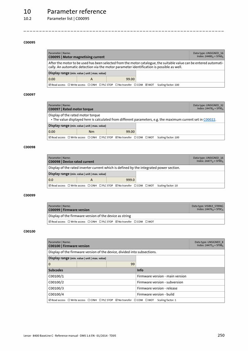
Lenze · 8400 BaseLine C · Reference manual · DMS 1.6 EN · 01/2014 · TD05 250
10 Parameter reference10.2 Parameter list | C00095
_ _ _ _ _ _ _ _ _ _ _ _ _ _ _ _ _ _ _ _ _ _ _ _ _ _ _ _ _ _ _ _ _ _ _ _ _ _ _ _ _ _ _ _ _ _ _ _ _ _ _ _ _ _ _ _ _ _ _ _ _ _ _ _
C00095
C00097
C00098
C00099
C00100
Parameter | Name:
C00095 | Motor magnetising currentData type: UNSIGNED_16
Index: 24480d = 5FA0h
After the motor to be used has been selected from the motor catalogue, the suitable value can be entered automati-cally. An automatic detection via the motor parameter identification is possible as well.
Display range (min. value | unit | max. value)
0.00 A 99.00
Read access Write access CINH PLC STOP No transfer COM MOT Scaling factor: 100
Parameter | Name:
C00097 | Rated motor torqueData type: UNSIGNED_32
Index: 24478d = 5F9Eh
Display of the rated motor torque• The value displayed here is calculated from different parameters, e.g. the maximum current set in C00022.
Display range (min. value | unit | max. value)
0.00 Nm 99.00
Read access Write access CINH PLC STOP No transfer COM MOT Scaling factor: 100
Parameter | Name:
C00098 | Device rated currentData type: UNSIGNED_16
Index: 24477d = 5F9Dh
Display of the rated inverter current which is defined by the integrated power section.
Display range (min. value | unit | max. value)
0.0 A 999.0
Read access Write access CINH PLC STOP No transfer COM MOT Scaling factor: 10
Parameter | Name:
C00099 | Firmware versionData type: VISIBLE_STRING
Index: 24476d = 5F9Ch
Display of the firmware version of the device as string
Read access Write access CINH PLC STOP No transfer COM MOT
Parameter | Name:
C00100 | Firmware versionData type: UNSIGNED_8
Index: 24475d = 5F9Bh
Display of the firmware version of the device, divided into subsections.
Display range (min. value | unit | max. value)
0 99
Subcodes Info
C00100/1 Firmware version - main version
C00100/2 Firmware version - subversion
C00100/3 Firmware version - release
C00100/4 Firmware version - build
Read access Write access CINH PLC STOP No transfer COM MOT Scaling factor: 1
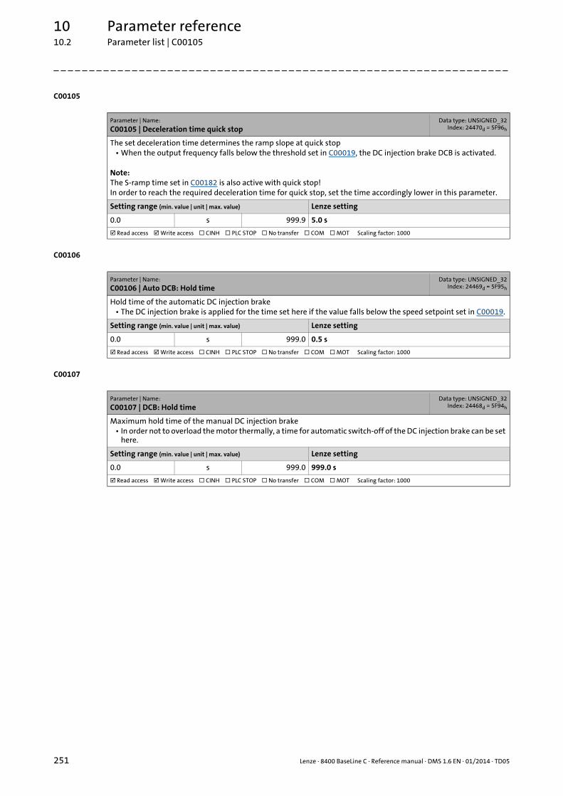
10 Parameter reference10.2 Parameter list | C00105
251 Lenze · 8400 BaseLine C · Reference manual · DMS 1.6 EN · 01/2014 · TD05
_ _ _ _ _ _ _ _ _ _ _ _ _ _ _ _ _ _ _ _ _ _ _ _ _ _ _ _ _ _ _ _ _ _ _ _ _ _ _ _ _ _ _ _ _ _ _ _ _ _ _ _ _ _ _ _ _ _ _ _ _ _ _ _
C00105
C00106
C00107
Parameter | Name:
C00105 | Deceleration time quick stopData type: UNSIGNED_32
Index: 24470d = 5F96h
The set deceleration time determines the ramp slope at quick stop• When the output frequency falls below the threshold set in C00019, the DC injection brake DCB is activated.
Note:The S-ramp time set in C00182 is also active with quick stop!In order to reach the required deceleration time for quick stop, set the time accordingly lower in this parameter.
Setting range (min. value | unit | max. value) Lenze setting
0.0 s 999.9 5.0 s
Read access Write access CINH PLC STOP No transfer COM MOT Scaling factor: 1000
Parameter | Name:
C00106 | Auto DCB: Hold timeData type: UNSIGNED_32
Index: 24469d = 5F95h
Hold time of the automatic DC injection brake• The DC injection brake is applied for the time set here if the value falls below the speed setpoint set in C00019.
Setting range (min. value | unit | max. value) Lenze setting
0.0 s 999.0 0.5 s
Read access Write access CINH PLC STOP No transfer COM MOT Scaling factor: 1000
Parameter | Name:
C00107 | DCB: Hold timeData type: UNSIGNED_32
Index: 24468d = 5F94h
Maximum hold time of the manual DC injection brake• In order not to overload the motor thermally, a time for automatic switch-off of the DC injection brake can be set
here.
Setting range (min. value | unit | max. value) Lenze setting
0.0 s 999.0 999.0 s
Read access Write access CINH PLC STOP No transfer COM MOT Scaling factor: 1000

Lenze · 8400 BaseLine C · Reference manual · DMS 1.6 EN · 01/2014 · TD05 252
10 Parameter reference10.2 Parameter list | C00114
_ _ _ _ _ _ _ _ _ _ _ _ _ _ _ _ _ _ _ _ _ _ _ _ _ _ _ _ _ _ _ _ _ _ _ _ _ _ _ _ _ _ _ _ _ _ _ _ _ _ _ _ _ _ _ _ _ _ _ _ _ _ _ _
C00114
C00118
Parameter | Name:
C00114 | DIx inversionData type: UNSIGNED_16
Index: 24461d = 5F8Dh
Polarity of the digital inputs• Every digital input of the device can be inverted with regard to polarity via this bit field.
Digital terminals
Setting range (min. hex value | max. hex value) Lenze setting
0x0000 0xFFFF 0x8000 (decimal: 32768)
Value is bit-coded: ( = bit set) Info
Bit 0 DI1 inverted Inversion of digital input 1
Bit 1 DI2 inverted Inversion of digital input 2
Bit 2 DI3 inverted Inversion of digital input 3
Bit 3 DI4 inverted Inversion of digital input 4
Bit 4 Reserved
Bit 5 Reserved
Bit 6 Reserved
Bit 7 Reserved
Bit 8 Reserved
Bit 9 Reserved
Bit 10 Reserved
Bit 11 Reserved
Bit 12 Reserved
Bit 13 Reserved
Bit 14 Reserved
Bit 15 RFR inverted Inversion of RFR digital input (controller enable)
Read access Write access CINH PLC STOP No transfer COM MOT
Parameter | Name:
C00118 | DOx inversionData type: UNSIGNED_8
Index: 24457d = 5F89h
Polarity of the digital outputs• Every digital output of the device can be inverted with regard to polarity via this bit field.
Digital terminals
Setting range (min. hex value | max. hex value) Lenze setting
0x00 0xFF 0x00 (decimal: 0)
Value is bit-coded: ( = bit set) Info
Bit 0 Relay inverted Relay inversion
Bit 1 DO1 inverted Inversion of digital output 1
Bit 2 Reserved
Bit 3 Reserved
Bit 4 Reserved
Bit 5 Reserved
Bit 6 Reserved
Bit 7 Reserved
Read access Write access CINH PLC STOP No transfer COM MOT

10 Parameter reference10.2 Parameter list | C00120
253 Lenze · 8400 BaseLine C · Reference manual · DMS 1.6 EN · 01/2014 · TD05
_ _ _ _ _ _ _ _ _ _ _ _ _ _ _ _ _ _ _ _ _ _ _ _ _ _ _ _ _ _ _ _ _ _ _ _ _ _ _ _ _ _ _ _ _ _ _ _ _ _ _ _ _ _ _ _ _ _ _ _ _ _ _ _
C00120
C00122
C00123
C00134
Parameter | Name:
C00120 | Motor overload threshold (I²xt)Data type: INTEGER_16Index: 24455d = 5F87h
Operating threshold for the error message "OC6: Motor overload (I²xt)"• The response for reaching the threshold can be selected in C00606.• The current thermal motor load is displayed in C00066.
Motor overload monitoring (I2xt)
Setting range (min. value | unit | max. value) Lenze setting
0 % 250 100 %
Read access Write access CINH PLC STOP No transfer COM MOT Scaling factor: 100
Parameter | Name:
C00122 | Initial value motor overload (I²xt)Data type: UNSIGNED_16
Index: 24453d = 5F85h
From version 03.04.00The thermal motor load displayed in C00066 is pre-initialised with the value set here when the device is connected to the mains.
• If "100.00 %" is set, the last value at switching off the device is used for the initialisation.• Recommended setting for operation according to UL: 50.00 %
Motor overload monitoring (I2xt)
Setting range (min. value | unit | max. value)
0.00 % 100.00
Subcodes Lenze setting Info
C00122/1 0.00 % Initial value motor overload (I²xt)
Read access Write access CINH PLC STOP No transfer COM MOT Scaling factor: 100
Parameter | Name:
C00123 | Device utilisation threshold (Ixt)Data type: INTEGER_16Index: 24452d = 5F84h
Operating threshold for the error message "OC5: Device overload (Ixt)"• The response for reaching the threshold can be selected in C00604.• The current device utilisation is displayed in C00064.
Setting range (min. value | unit | max. value) Lenze setting
0 % 100 100 %
Read access Write access CINH PLC STOP No transfer COM MOT Scaling factor: 100
Parameter | Name:
C00134 | Ramp smoothing, main setpointData type: UNSIGNED_8
Index: 24441d = 5F79h
FB L_NSet_1: Configuration of the ramp smoothing for the main setpoint
Selection list (Lenze setting printed in bold) Info
0 Off Ramp rounding deactivated
1 PT1 behaviour Ramp rounding with PT1 behaviour• The corresponding S-ramp time must be set in
C00182.
Read access Write access CINH PLC STOP No transfer COM MOT Scaling factor: 1

Lenze · 8400 BaseLine C · Reference manual · DMS 1.6 EN · 01/2014 · TD05 254
10 Parameter reference10.2 Parameter list | C00136
_ _ _ _ _ _ _ _ _ _ _ _ _ _ _ _ _ _ _ _ _ _ _ _ _ _ _ _ _ _ _ _ _ _ _ _ _ _ _ _ _ _ _ _ _ _ _ _ _ _ _ _ _ _ _ _ _ _ _ _ _ _ _ _
C00136
Parameter | Name:
C00136 | Communication control wordsData type: UNSIGNED_16
Index: 24439d = 5F77h
Control words of the communication interfaces
Display area (min. hex value | max. hex value)
0x0000 0xFFFF
Value is bit-coded:
Bit 0 SwitchOn
Bit 1 IMP
Bit 2 SetQuickStop
Bit 3 EnableOperation
Bit 4 Reserved
Bit 5 Reserved
Bit 6 Reserved
Bit 7 ResetFault
Bit 8 SetHalt
Bit 9 reserved_1
Bit 10 reserved_2
Bit 11 LenzeSpecific_1
Bit 12 LenzeSpecific_2
Bit 13 LenzeSpecific_3
Bit 14 SetFail
Bit 15 LenzeSpecific_4
Subcodes Info
C00136/1 Reserved
C00136/2 CAN control word• Control word of the communication interface CAN
(CAN on board)
Read access Write access CINH PLC STOP No transfer COM MOT

10 Parameter reference10.2 Parameter list | C00137
255 Lenze · 8400 BaseLine C · Reference manual · DMS 1.6 EN · 01/2014 · TD05
_ _ _ _ _ _ _ _ _ _ _ _ _ _ _ _ _ _ _ _ _ _ _ _ _ _ _ _ _ _ _ _ _ _ _ _ _ _ _ _ _ _ _ _ _ _ _ _ _ _ _ _ _ _ _ _ _ _ _ _ _ _ _ _
C00137
C00141
Parameter | Name:
C00137 | Device stateData type: UNSIGNED_16
Index: 24438d = 5F76h
Display of the current device state
Selection list (read only)
0 Reserved
1 Init
2 MotorIdent
3 ReadyToSwitchON
4 SwitchedON
5 OperationEnable
6 Reserved
7 Trouble
8 Fault
9 Reserved
10 SafeTorqueOff
11 Reserved
12 Reserved
13 Reserved
14 Reserved
15 Reserved
Read access Write access CINH PLC STOP No transfer COM MOT Scaling factor: 1
Parameter | Name:
C00141 | Device settingsData type: UNSIGNED_8
Index: 24434d = 5F72h
As of version 03.00.00
Selection list
0 Inactive
1 Active
Subcodes Lenze setting Info
C00141/1 0: Inactive Always save parameters• When this function is activated, every parameter
change is saved in the memory module. A manual sa-ving of parameter sets is not required anymore.
Note:Activating this function is not permissible if parameters are changed very frequently (e.g. in case of cyclic writing of parameters via a bus system).
Read access Write access CINH PLC STOP No transfer COM MOT Scaling factor: 1
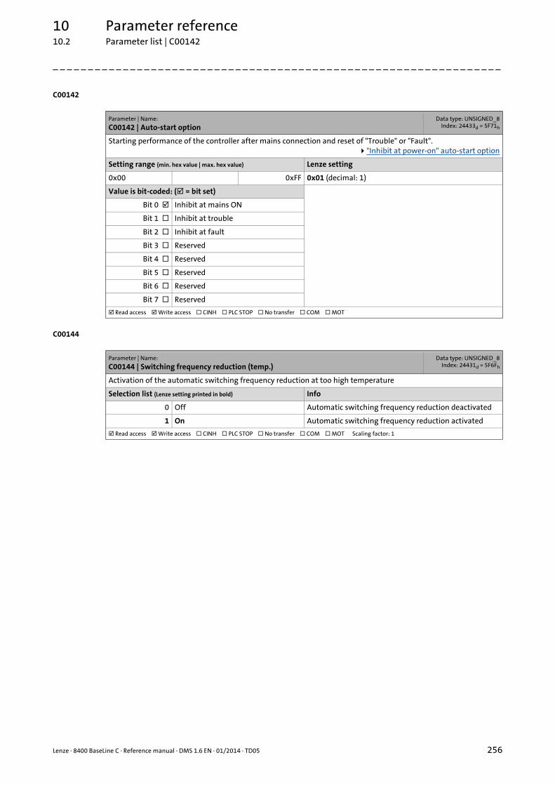
Lenze · 8400 BaseLine C · Reference manual · DMS 1.6 EN · 01/2014 · TD05 256
10 Parameter reference10.2 Parameter list | C00142
_ _ _ _ _ _ _ _ _ _ _ _ _ _ _ _ _ _ _ _ _ _ _ _ _ _ _ _ _ _ _ _ _ _ _ _ _ _ _ _ _ _ _ _ _ _ _ _ _ _ _ _ _ _ _ _ _ _ _ _ _ _ _ _
C00142
C00144
Parameter | Name:
C00142 | Auto-start optionData type: UNSIGNED_8
Index: 24433d = 5F71h
Starting performance of the controller after mains connection and reset of "Trouble" or "Fault"."Inhibit at power-on" auto-start option
Setting range (min. hex value | max. hex value) Lenze setting
0x00 0xFF 0x01 (decimal: 1)
Value is bit-coded: ( = bit set)
Bit 0 Inhibit at mains ON
Bit 1 Inhibit at trouble
Bit 2 Inhibit at fault
Bit 3 Reserved
Bit 4 Reserved
Bit 5 Reserved
Bit 6 Reserved
Bit 7 Reserved
Read access Write access CINH PLC STOP No transfer COM MOT
Parameter | Name:
C00144 | Switching frequency reduction (temp.)Data type: UNSIGNED_8
Index: 24431d = 5F6Fh
Activation of the automatic switching frequency reduction at too high temperature
Selection list (Lenze setting printed in bold) Info
0 Off Automatic switching frequency reduction deactivated
1 On Automatic switching frequency reduction activated
Read access Write access CINH PLC STOP No transfer COM MOT Scaling factor: 1
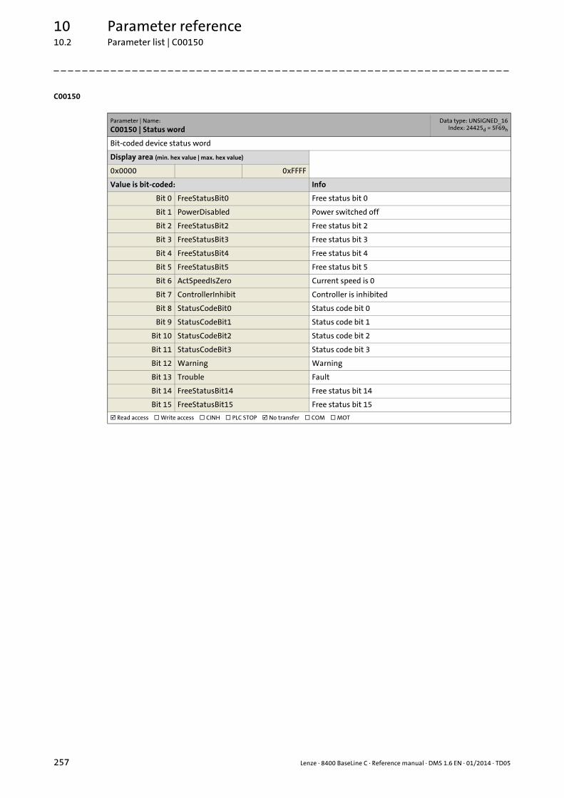
10 Parameter reference10.2 Parameter list | C00150
257 Lenze · 8400 BaseLine C · Reference manual · DMS 1.6 EN · 01/2014 · TD05
_ _ _ _ _ _ _ _ _ _ _ _ _ _ _ _ _ _ _ _ _ _ _ _ _ _ _ _ _ _ _ _ _ _ _ _ _ _ _ _ _ _ _ _ _ _ _ _ _ _ _ _ _ _ _ _ _ _ _ _ _ _ _ _
C00150
Parameter | Name:
C00150 | Status wordData type: UNSIGNED_16
Index: 24425d = 5F69h
Bit-coded device status word
Display area (min. hex value | max. hex value)
0x0000 0xFFFF
Value is bit-coded: Info
Bit 0 FreeStatusBit0 Free status bit 0
Bit 1 PowerDisabled Power switched off
Bit 2 FreeStatusBit2 Free status bit 2
Bit 3 FreeStatusBit3 Free status bit 3
Bit 4 FreeStatusBit4 Free status bit 4
Bit 5 FreeStatusBit5 Free status bit 5
Bit 6 ActSpeedIsZero Current speed is 0
Bit 7 ControllerInhibit Controller is inhibited
Bit 8 StatusCodeBit0 Status code bit 0
Bit 9 StatusCodeBit1 Status code bit 1
Bit 10 StatusCodeBit2 Status code bit 2
Bit 11 StatusCodeBit3 Status code bit 3
Bit 12 Warning Warning
Bit 13 Trouble Fault
Bit 14 FreeStatusBit14 Free status bit 14
Bit 15 FreeStatusBit15 Free status bit 15
Read access Write access CINH PLC STOP No transfer COM MOT

Lenze · 8400 BaseLine C · Reference manual · DMS 1.6 EN · 01/2014 · TD05 258
10 Parameter reference10.2 Parameter list | C00155
_ _ _ _ _ _ _ _ _ _ _ _ _ _ _ _ _ _ _ _ _ _ _ _ _ _ _ _ _ _ _ _ _ _ _ _ _ _ _ _ _ _ _ _ _ _ _ _ _ _ _ _ _ _ _ _ _ _ _ _ _ _ _ _
C00155
Parameter | Name:
C00155 | Status word 2Data type: UNSIGNED_16
Index: 24420d = 5F64h
Bit-coded device status word 2
Display area (min. hex value | max. hex value)
0x0000 0xFFFF
Value is bit-coded: Info
Bit 0 Fail Error
Bit 1 M_max Maximum torque
Bit 2 I_max Maximum current
Bit 3 PowerDisabled Power switched off
Bit 4 Ready Controller is ready for operation
Bit 5 ControllerInhibit Controller is inhibited
Bit 6 Trouble Fault
Bit 7 InitState Initialisation
Bit 8 CwCcw CW/CCW rotation
Bit 9 Reserved
Bit 10 SafeTorqueOff Safe torque off
Bit 11 Reserved
Bit 12 Reserved
Bit 13 Reserved
Bit 14 Quick stop Quick stop is active
Bit 15 MotorIdent Motor parameter identification active
Read access Write access CINH PLC STOP No transfer COM MOT

10 Parameter reference10.2 Parameter list | C00158
259 Lenze · 8400 BaseLine C · Reference manual · DMS 1.6 EN · 01/2014 · TD05
_ _ _ _ _ _ _ _ _ _ _ _ _ _ _ _ _ _ _ _ _ _ _ _ _ _ _ _ _ _ _ _ _ _ _ _ _ _ _ _ _ _ _ _ _ _ _ _ _ _ _ _ _ _ _ _ _ _ _ _ _ _ _ _
C00158
Parameter | Name:
C00158 | Cause for controller inhibitData type: UNSIGNED_16
Index: 24417d = 5F61h
Bit-coded display of the cause/source of controller inhibit
Display area (min. hex value | max. hex value)
0x0000 0xFFFF
Value is bit-coded:
Bit 0 Terminal controller enable
Bit 1 CANDriveControl
Bit 2 Reserved
Bit 3 SwitchOn
Bit 4 Application
Bit 5 Device command
Bit 6 Error response
Bit 7 Reserved
Bit 8 Reserved
Bit 9 Reserved
Bit 10 AutoStartLock
Bit 11 Motor parameter identification
Bit 12 Reserved
Bit 13 DCB-IMP
Bit 14 Reserved
Bit 15 Reserved
Read access Write access CINH PLC STOP No transfer COM MOT

Lenze · 8400 BaseLine C · Reference manual · DMS 1.6 EN · 01/2014 · TD05 260
10 Parameter reference10.2 Parameter list | C00159
_ _ _ _ _ _ _ _ _ _ _ _ _ _ _ _ _ _ _ _ _ _ _ _ _ _ _ _ _ _ _ _ _ _ _ _ _ _ _ _ _ _ _ _ _ _ _ _ _ _ _ _ _ _ _ _ _ _ _ _ _ _ _ _
C00159
C00165
C00166
Parameter | Name:
C00159 | Cause for quick stop QSPData type: UNSIGNED_16
Index: 24416d = 5F60h
Bit-coded display of the cause/source of quick stop
Display area (min. hex value | max. hex value)
0x0000 0xFFFF
Value is bit-coded:
Bit 0 Terminal
Bit 1 CANDriveControl
Bit 2 Reserved
Bit 3 SwitchOn
Bit 4 Application
Bit 5 Device command
Bit 6 Reserved
Bit 7 Reserved
Bit 8 Reserved
Bit 9 Reserved
Bit 10 Reserved
Bit 11 Reserved
Bit 12 Reserved
Bit 13 Reserved
Bit 14 Reserved
Bit 15 Reserved
Read access Write access CINH PLC STOP No transfer COM MOT
Parameter | Name:
C00165 | Error informationData type: VISIBLE_STRING
Index: 24410d = 5F5Ah
Display of the error numbers divided into sectors in the case of an error
Subcodes Info
C00165/1 Current error
Read access Write access CINH PLC STOP No transfer COM MOT
Parameter | Name:
C00166 | Error information textData type: VISIBLE_STRING
Index: 24409d = 5F59h
Display of details of the currently pending error
Subcodes Info
C00166/1 Resp. - current error• Response of the currently pending error
C00166/2 Subj.area curr. error• Subject area of the currently pending error
C00166/3 Mess.curr.error• Textual message of the currently pending error
Read access Write access CINH PLC STOP No transfer COM MOT

10 Parameter reference10.2 Parameter list | C00167
261 Lenze · 8400 BaseLine C · Reference manual · DMS 1.6 EN · 01/2014 · TD05
_ _ _ _ _ _ _ _ _ _ _ _ _ _ _ _ _ _ _ _ _ _ _ _ _ _ _ _ _ _ _ _ _ _ _ _ _ _ _ _ _ _ _ _ _ _ _ _ _ _ _ _ _ _ _ _ _ _ _ _ _ _ _ _
C00167
C00168
C00169
C00170
C00171
Parameter | Name:
C00167 | Logbook dataData type: OCTET_STRING
Index: 24408d = 5F58h
This code is for device-internal use only and must not be written to by the user!
Parameter | Name:
C00168 | Error numberData type: UNSIGNED_32
Index: 24407d = 5F57h
Display range (min. value | unit | max. value)
0 4294967295
Subcodes Info
C00168/1 Display of the internal error number for the last 8 occur-red errors
C00168/...
C00168/8
Read access Write access CINH PLC STOP No transfer COM MOT Scaling factor: 1
Parameter | Name:
C00169 | Time of errorData type: UNSIGNED_32
Index: 24406d = 5F56h
Display range (min. value | unit | max. value)
0 4294967295
Subcodes Info
C00169/1 Display of the time of error for the last 8 occurred errors
C00169/...
C00169/8
Read access Write access CINH PLC STOP No transfer COM MOT Scaling factor: 1
Parameter | Name:
C00170 | Error counterData type: UNSIGNED_8
Index: 24405d = 5F55h
Display range (min. value | unit | max. value)
0 255
Subcodes Info
C00170/1 Display of the error counter for the last 8 occurred errors
C00170/...
C00170/8
Read access Write access CINH PLC STOP No transfer COM MOT Scaling factor: 1
Parameter | Name:
C00171 | Logbook access indexData type: UNSIGNED_8
Index: 24404d = 5F54h
This code is for device-internal use only and must not be written to by the user!

Lenze · 8400 BaseLine C · Reference manual · DMS 1.6 EN · 01/2014 · TD05 262
10 Parameter reference10.2 Parameter list | C00173
_ _ _ _ _ _ _ _ _ _ _ _ _ _ _ _ _ _ _ _ _ _ _ _ _ _ _ _ _ _ _ _ _ _ _ _ _ _ _ _ _ _ _ _ _ _ _ _ _ _ _ _ _ _ _ _ _ _ _ _ _ _ _ _
C00173
C00174
C00177
C00178
C00179
Parameter | Name:
C00173 | Mains voltageData type: UNSIGNED_8
Index: 24402d = 5F52h
Selection of the mains voltage for operating the device.
Selection list (Lenze setting printed in bold) Info
0 3ph 400V / 1ph 230V 3-phase 400 V or 1-phase 230 V
1 3ph 440V / 1ph 230V 3-phase 440 V or 1-phase 230 V
2 3ph 480V / 1ph 230V 3-phase 480 V or 1-phase 230 V
3 3ph 500V / 1ph 230V 3-phase 500 V or 1-phase 230 V
Read access Write access CINH PLC STOP No transfer COM MOT Scaling factor: 1
Parameter | Name:
C00174 | Reduced brake chopper thresholdData type: UNSIGNED_8
Index: 24401d = 5F51h
The threshold from which on the brake chopper is controlled is reduced by the voltage value set here.
Setting range (min. value | unit | max. value) Lenze setting
0 V 150 0 V
Read access Write access CINH PLC STOP No transfer COM MOT Scaling factor: 1
Parameter | Name:
C00177 | Switching cyclesData type: UNSIGNED_32
Index: 24398d = 5F4Eh
Counter of different switching cycles and stressful situations
Display range (min. value | unit | max. value)
0 2147483647
Subcodes Info
C00177/1 Number of mains switching cycles
C00177/2 Number of switching cycles of the output relay
Read access Write access CINH PLC STOP No transfer COM MOT Scaling factor: 1
Parameter | Name:
C00178 | Elapsed-hour meterData type: UNSIGNED_32
Index: 24397d = 5F4Dh
Display of the operating hours in "seconds" unit
Display range (min. value | unit | max. value)
0 s 2147483647
Read access Write access CINH PLC STOP No transfer COM MOT Scaling factor: 1
Parameter | Name:
C00179 | Power-on time meterData type: UNSIGNED_32
Index: 24396d = 5F4Ch
Display of the power-on time in "seconds" unit
Display range (min. value | unit | max. value)
0 s 2147483647
Read access Write access CINH PLC STOP No transfer COM MOT Scaling factor: 1

10 Parameter reference10.2 Parameter list | C00182
263 Lenze · 8400 BaseLine C · Reference manual · DMS 1.6 EN · 01/2014 · TD05
_ _ _ _ _ _ _ _ _ _ _ _ _ _ _ _ _ _ _ _ _ _ _ _ _ _ _ _ _ _ _ _ _ _ _ _ _ _ _ _ _ _ _ _ _ _ _ _ _ _ _ _ _ _ _ _ _ _ _ _ _ _ _ _
C00182
C00200
C00201
C00203
C00222
Parameter | Name:
C00182 | S-ramp time PT1Data type: INTEGER_16Index: 24393d = 5F49h
FB L_NSet_1: PT1 S-ramp time for the main setpoint ramp function generator• Only effective with activated ramp smoothing (C00134 = "1").
Setting range (min. value | unit | max. value) Lenze setting
0.01 s 50.00 20.00 s
Read access Write access CINH PLC STOP No transfer COM MOT Scaling factor: 100
Parameter | Name:
C00200 | Firmware product typeData type: VISIBLE_STRING
Index: 24375d = 5F37h
Display of the firmware product type
Read access Write access CINH PLC STOP No transfer COM MOT
Parameter | Name:
C00201 | Firmware compile dateData type: VISIBLE_STRING
Index: 24374d = 5F36h
Display of the firmware compilation date
Read access Write access CINH PLC STOP No transfer COM MOT
Parameter | Name:
C00203 | Product type codeData type: VISIBLE_STRING
Index: 24372d = 5F34h
As of version 03.00.00Display of the single device component types
Subcodes Info
C00203/1 Reserved
C00203/2 Reserved
C00203/3 Reserved
C00203/4 Type: I/O micro
C00203/5 Type: Memory module
C00203/6 Type: Safety module
C00203/7 Reserved
C00203/8 Type: Complete device
C00203/9 Reserved
Read access Write access CINH PLC STOP No transfer COM MOT
Parameter | Name:
C00222 | L_PCTRL_1: VpData type: INTEGER_16Index: 24353d = 5F21h
FB L_PCTRL_1: Gain factor Vp for the PID process controller
Setting range (min. value | unit | max. value) Lenze setting
0.1 500.0 1.0
Read access Write access CINH PLC STOP No transfer COM MOT Scaling factor: 10

Lenze · 8400 BaseLine C · Reference manual · DMS 1.6 EN · 01/2014 · TD05 264
10 Parameter reference10.2 Parameter list | C00223
_ _ _ _ _ _ _ _ _ _ _ _ _ _ _ _ _ _ _ _ _ _ _ _ _ _ _ _ _ _ _ _ _ _ _ _ _ _ _ _ _ _ _ _ _ _ _ _ _ _ _ _ _ _ _ _ _ _ _ _ _ _ _ _
C00223
C00224
C00225
C00226
C00227
Parameter | Name:
C00223 | L_PCTRL_1: TnData type: UNSIGNED_16
Index: 24352d = 5F20h
FB L_PCTRL_1: Reset time Tn for the PID process controller
Setting range (min. value | unit | max. value) Lenze setting
20 ms 6000 400 ms
Read access Write access CINH PLC STOP No transfer COM MOT Scaling factor: 1
Parameter | Name:
C00224 | L_PCTRL_1: KdData type: UNSIGNED_16
Index: 24351d = 5F1Fh
FB L_PCTRL_1: Derivative-action coefficient Kd for the PID process controller
Setting range (min. value | unit | max. value) Lenze setting
0.0 5.0 0.0
Read access Write access CINH PLC STOP No transfer COM MOT Scaling factor: 10
Parameter | Name:
C00225 | L_PCTRL_1: MaxLimitData type: INTEGER_16
Index: 24350d = 5F1Eh
FB L_PCTRL_1: Maximum output value of the PID process controller
Setting range (min. value | unit | max. value) Lenze setting
-199.9 % 199.9 199.9 %
Read access Write access CINH PLC STOP No transfer COM MOT Scaling factor: 100
Parameter | Name:
C00226 | L_PCTRL_1: MinLimitData type: INTEGER_16Index: 24349d = 5F1Dh
FB L_PCTRL_1: Minimum output value of the PID process controller
Setting range (min. value | unit | max. value) Lenze setting
-199.9 % 199.9 -199.9 %
Read access Write access CINH PLC STOP No transfer COM MOT Scaling factor: 100
Parameter | Name:
C00227 | L_PCTRL_1: Acceleration timeData type: UNSIGNED_32
Index: 24348d = 5F1Ch
FB L_PCTRL_1: Acceleration time for the output value of the PID process controller
Setting range (min. value | unit | max. value) Lenze setting
0.0 s 999.9 0.1 s
Read access Write access CINH PLC STOP No transfer COM MOT Scaling factor: 1000
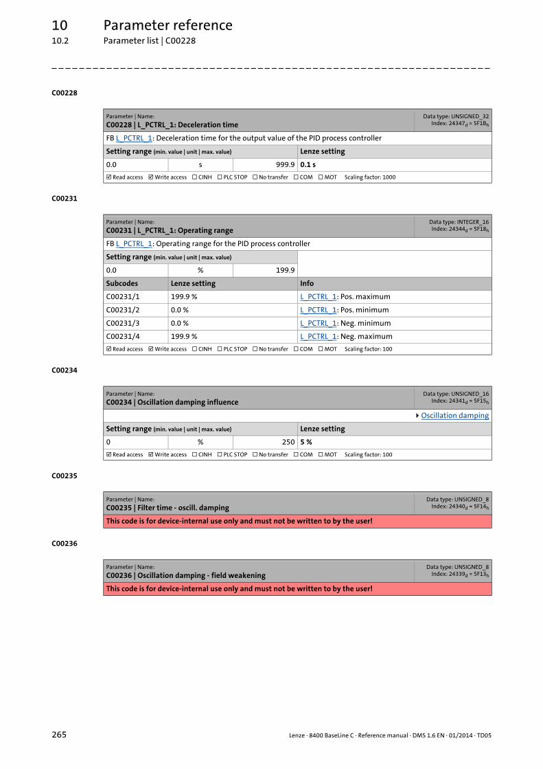
10 Parameter reference10.2 Parameter list | C00228
265 Lenze · 8400 BaseLine C · Reference manual · DMS 1.6 EN · 01/2014 · TD05
_ _ _ _ _ _ _ _ _ _ _ _ _ _ _ _ _ _ _ _ _ _ _ _ _ _ _ _ _ _ _ _ _ _ _ _ _ _ _ _ _ _ _ _ _ _ _ _ _ _ _ _ _ _ _ _ _ _ _ _ _ _ _ _
C00228
C00231
C00234
C00235
C00236
Parameter | Name:
C00228 | L_PCTRL_1: Deceleration timeData type: UNSIGNED_32
Index: 24347d = 5F1Bh
FB L_PCTRL_1: Deceleration time for the output value of the PID process controller
Setting range (min. value | unit | max. value) Lenze setting
0.0 s 999.9 0.1 s
Read access Write access CINH PLC STOP No transfer COM MOT Scaling factor: 1000
Parameter | Name:
C00231 | L_PCTRL_1: Operating rangeData type: INTEGER_16Index: 24344d = 5F18h
FB L_PCTRL_1: Operating range for the PID process controller
Setting range (min. value | unit | max. value)
0.0 % 199.9
Subcodes Lenze setting Info
C00231/1 199.9 % L_PCTRL_1: Pos. maximum
C00231/2 0.0 % L_PCTRL_1: Pos. minimum
C00231/3 0.0 % L_PCTRL_1: Neg. minimum
C00231/4 199.9 % L_PCTRL_1: Neg. maximum
Read access Write access CINH PLC STOP No transfer COM MOT Scaling factor: 100
Parameter | Name:
C00234 | Oscillation damping influenceData type: UNSIGNED_16
Index: 24341d = 5F15h
Oscillation damping
Setting range (min. value | unit | max. value) Lenze setting
0 % 250 5 %
Read access Write access CINH PLC STOP No transfer COM MOT Scaling factor: 100
Parameter | Name:
C00235 | Filter time - oscill. dampingData type: UNSIGNED_8
Index: 24340d = 5F14h
This code is for device-internal use only and must not be written to by the user!
Parameter | Name:
C00236 | Oscillation damping - field weakeningData type: UNSIGNED_8
Index: 24339d = 5F13h
This code is for device-internal use only and must not be written to by the user!
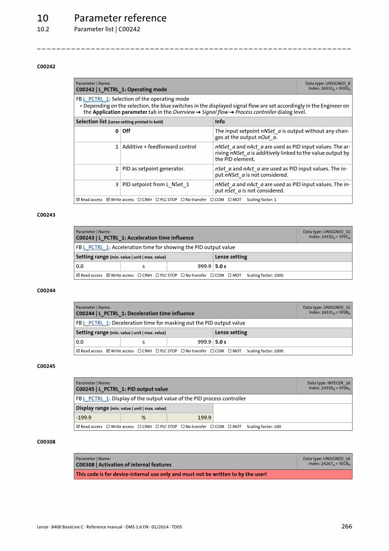
Lenze · 8400 BaseLine C · Reference manual · DMS 1.6 EN · 01/2014 · TD05 266
10 Parameter reference10.2 Parameter list | C00242
_ _ _ _ _ _ _ _ _ _ _ _ _ _ _ _ _ _ _ _ _ _ _ _ _ _ _ _ _ _ _ _ _ _ _ _ _ _ _ _ _ _ _ _ _ _ _ _ _ _ _ _ _ _ _ _ _ _ _ _ _ _ _ _
C00242
C00243
C00244
C00245
C00308
Parameter | Name:
C00242 | L_PCTRL_1: Operating modeData type: UNSIGNED_8
Index: 24333d = 5F0Dh
FB L_PCTRL_1: Selection of the operating mode• Depending on the selection, the blue switches in the displayed signal flow are set accordingly in the Engineer on
the Application parameter tab in the Overview Signal flow Process controller dialog level.
Selection list (Lenze setting printed in bold) Info
0 Off The input setpoint nNSet_a is output without any chan-ges at the output nOut_a.
1 Additive + feedforward control nNSet_a and nAct_a are used as PID input values. The ar-riving nNSet_a is additively linked to the value output by the PID element.
2 PID as setpoint generator. nSet_a and nAct_a are used as PID input values. The in-put nNSet_a is not considered.
3 PID setpoint from L_NSet_1 nNSet_a and nAct_a are used as PID input values. The in-put nSet_a is not considered.
Read access Write access CINH PLC STOP No transfer COM MOT Scaling factor: 1
Parameter | Name:
C00243 | L_PCTRL_1: Acceleration time influenceData type: UNSIGNED_32
Index: 24332d = 5F0Ch
FB L_PCTRL_1: Acceleration time for showing the PID output value
Setting range (min. value | unit | max. value) Lenze setting
0.0 s 999.9 5.0 s
Read access Write access CINH PLC STOP No transfer COM MOT Scaling factor: 1000
Parameter | Name:
C00244 | L_PCTRL_1: Deceleration time influenceData type: UNSIGNED_32
Index: 24331d = 5F0Bh
FB L_PCTRL_1: Deceleration time for masking out the PID output value
Setting range (min. value | unit | max. value) Lenze setting
0.0 s 999.9 5.0 s
Read access Write access CINH PLC STOP No transfer COM MOT Scaling factor: 1000
Parameter | Name:
C00245 | L_PCTRL_1: PID output valueData type: INTEGER_16Index: 24330d = 5F0Ah
FB L_PCTRL_1: Display of the output value of the PID process controller
Display range (min. value | unit | max. value)
-199.9 % 199.9
Read access Write access CINH PLC STOP No transfer COM MOT Scaling factor: 100
Parameter | Name:
C00308 | Activation of internal featuresData type: UNSIGNED_16
Index: 24267d = 5ECBh
This code is for device-internal use only and must not be written to by the user!

10 Parameter reference10.2 Parameter list | C00309
267 Lenze · 8400 BaseLine C · Reference manual · DMS 1.6 EN · 01/2014 · TD05
_ _ _ _ _ _ _ _ _ _ _ _ _ _ _ _ _ _ _ _ _ _ _ _ _ _ _ _ _ _ _ _ _ _ _ _ _ _ _ _ _ _ _ _ _ _ _ _ _ _ _ _ _ _ _ _ _ _ _ _ _ _ _ _
C00309
C00322
C00323
Parameter | Name:
C00309 | Delay timeData type: UNSIGNED_16
Index: 24266d = 5ECAh
This code is for device-internal use only and must not be written to by the user!
Parameter | Name:
C00322 | Transmission mode CAN TxPDOsData type: UNSIGNED_8
Index: 24253d = 5EBDh
TPDO transmission type according to DS301 V4.02• The following transmission modes are supported:
• 0: Synchronous and acyclic• 1 ... 240: Synchronous and cyclic• 252: Synchronous - only RTR• 253: Asynchronous - only RTR• 254: Asynchronous - manufacturer-specific• 255: Asynchronous - device profile specific
• The basic setting for all PDOs is the "asynchronous - manufacturer-specific" setting (254).• Mapping of the CANopen objects I-1800/2 and I-1801/2 (see DS301 V4.02).
System bus "CAN on board"
Setting range (min. value | unit | max. value)
0 255
Subcodes Lenze setting Info
C00322/1 254 Transmission mode CAN1 OUT
C00322/2 254 Transmission mode CAN2 OUT
Read access Write access CINH PLC STOP No transfer COM MOT Scaling factor: 1
Parameter | Name:
C00323 | Transmission mode CAN Rx PDOsData type: UNSIGNED_8
Index: 24252d = 5EBCh
RPDO transmission type according to DS301 V4.02• In the case of the RPDO serves as monitoring setting in the case of sync-controlled PDOs.• The following transmission modes are supported:
• 0: Synchronous and acyclic• 1 ... 240: Synchronous and cyclic• 252: Synchronous - only RTR• 253: Asynchronous - only RTR• 254: Asynchronous - manufacturer-specific• 255: Asynchronous - device profile specific
• The basic setting for all PDOs is the "asynchronous - manufacturer-specific" setting (254).• Mapping of the CANopen objects I-1400/2 and I-1401/2 (see DS301 V4.02).
System bus "CAN on board"
Setting range (min. value | unit | max. value)
0 255
Subcodes Lenze setting Info
C00323/1 254 Transmission mode CAN1 IN
C00323/2 254 Transmission mode CAN2 IN
Read access Write access CINH PLC STOP No transfer COM MOT Scaling factor: 1

Lenze · 8400 BaseLine C · Reference manual · DMS 1.6 EN · 01/2014 · TD05 268
10 Parameter reference10.2 Parameter list | C00324
_ _ _ _ _ _ _ _ _ _ _ _ _ _ _ _ _ _ _ _ _ _ _ _ _ _ _ _ _ _ _ _ _ _ _ _ _ _ _ _ _ _ _ _ _ _ _ _ _ _ _ _ _ _ _ _ _ _ _ _ _ _ _ _
C00324
C00345
Parameter | Name:
C00324 | CAN transmit blocking timeData type: UNSIGNED_16
Index: 24251d = 5EBBh
As of version 03.03.00Blocking time for transmitting the emergency telegram and the process data
Note:If the "asynchronous - manufacturer-specific/device-profile specific" transmission type has been set, the transmis-sion cycle timer is reset to 0 if transmission has been triggered in an event-controlled manner.
Example: Cycle time (C00356/x) = 500 ms, blocking time = 100 ms, sporadic data change:• In case of a sporadic data change < 500 ms, fastest transmission is every 100 ms due to the set blocking time
(event-controlled transmission).• In case of a sporadic data change > 500 ms, fastest transmission is every 500 ms due to the set blocking time (cy-
clic transmission).System bus "CAN on board"
Setting range (min. value | unit | max. value)
0 ms 6500
Subcodes Lenze setting Info
C00324/1 0 ms Emergency blocking time
C00324/2 0 ms CAN1_OUT blocking time
C00324/3 0 ms CAN2_OUT blocking time
Read access Write access CINH PLC STOP No transfer COM MOT Scaling factor: 1
Parameter | Name:
C00345 | CAN error statusData type: UNSIGNED_8
Index: 24230d = 5EA6h
System bus "CAN on board"
Selection list (read only)
0 No Error
1 Warning ErrActive
2 Warning ErrPassive
3 Bus off
4 Reserved
5 Reserved
Read access Write access CINH PLC STOP No transfer COM MOT Scaling factor: 1

10 Parameter reference10.2 Parameter list | C00347
269 Lenze · 8400 BaseLine C · Reference manual · DMS 1.6 EN · 01/2014 · TD05
_ _ _ _ _ _ _ _ _ _ _ _ _ _ _ _ _ _ _ _ _ _ _ _ _ _ _ _ _ _ _ _ _ _ _ _ _ _ _ _ _ _ _ _ _ _ _ _ _ _ _ _ _ _ _ _ _ _ _ _ _ _ _ _
C00347
C00350
C00351
Parameter | Name:
C00347 | CAN status HeartBeat producerData type: UNSIGNED_8
Index: 24228d = 5EA4h
System bus "CAN on board": Heartbeat protocol
Selection list (read only)
0 Boot-up
4 Stopped
5 Operational
127 Pre-Operational
250 Failed
255 NoResponse
Subcodes Info
C00347/1 Status node 1
Read access Write access CINH PLC STOP No transfer COM MOT Scaling factor: 1
Parameter | Name:
C00350 | CAN node addressData type: UNSIGNED_8
Index: 24225d = 5EA1h
Setting of the node address via parameters• The node address can only be parameterised if the node address "0" is set via the DIP switches.• A change of the node address will only become effective after a CAN reset node.
System bus "CAN on board"
Setting range (min. value | unit | max. value) Lenze setting
1 63 1
Read access Write access CINH PLC STOP No transfer COM MOT Scaling factor: 1
Parameter | Name:
C00351 | CAN baud rateData type: UNSIGNED_8
Index: 24224d = 5EA0h
Setting of the baud rate via parameters• The baud rate can only be parameterised if the baud rate "0" is set via the DIP switches.• A change of the baud rate will only become effective after a CAN reset node.
System bus "CAN on board"
Selection list (Lenze setting printed in bold)
0 500 kbps
1 250 kbps
2 125 kbps
3 50 kbps
4 1000 kbps
5 20 kbps
Read access Write access CINH PLC STOP No transfer COM MOT Scaling factor: 1

Lenze · 8400 BaseLine C · Reference manual · DMS 1.6 EN · 01/2014 · TD05 270
10 Parameter reference10.2 Parameter list | C00352
_ _ _ _ _ _ _ _ _ _ _ _ _ _ _ _ _ _ _ _ _ _ _ _ _ _ _ _ _ _ _ _ _ _ _ _ _ _ _ _ _ _ _ _ _ _ _ _ _ _ _ _ _ _ _ _ _ _ _ _ _ _ _ _
C00352
C00353
C00354
Parameter | Name:
C00352 | CAN Slave/MasterData type: UNSIGNED_8
Index: 24223d = 5E9Fh
The drive starts as CAN master after mains switching if the value "1" has been entered and saved here.System bus "CAN on board"
Selection list (Lenze setting printed in bold)
0 Slave
1 Master
Read access Write access CINH PLC STOP No transfer COM MOT Scaling factor: 1
Parameter | Name:
C00353 | CAN IN/OUT COBID sourceData type: UNSIGNED_8
Index: 24222d = 5E9Eh
Identifier allocation procedure for the CANx In/OUT process dataSystem bus "CAN on board"
Selection list Info
0 COBID = C0350 + LenzeBaseID COBID = device address + LenzeBaseID
1 COBID = C0350 + CANBaseID COBID = device address + CANBaseID (C00354/x)
2 COBID = C0354/x COBID = C00354/x + 384
Subcodes Lenze setting Info
C00353/1 1: COBID = C0350 + CANBaseID COBID source CAN1_IN/OUT
C00353/2 1: COBID = C0350 + CANBaseID COBID source CAN2_IN/OUT
Read access Write access CINH PLC STOP No transfer COM MOT Scaling factor: 1
Parameter | Name:
C00354 | COBIDData type: UNSIGNED_32
Index: 24221d = 5E9Dh
Setting of the default COBID according to CANopen• A change of the COBID will only become effective after a CAN reset node.
System bus "CAN on board"
Setting range (min. hex value | max. hex value)
0x00000000 0xFFFFFFFF
Value is bit-coded: Info
Bit 0 COBID Bit0 • Bit 0 ... 10: COB-ID• Bit 11 ... 30: Reserved• Bit 31: PDO invalid (is not transmitted)
... ...
Bit 31 PDO invalid
Subcodes Lenze setting Info
C00354/1 513 COBID CAN1_IN
C00354/2 385 COBID CAN1_OUT
C00354/3 769 COBID CAN2_IN
C00354/4 641 COBID CAN2_OUT
Read access Write access CINH PLC STOP No transfer COM MOT

10 Parameter reference10.2 Parameter list | C00355
271 Lenze · 8400 BaseLine C · Reference manual · DMS 1.6 EN · 01/2014 · TD05
_ _ _ _ _ _ _ _ _ _ _ _ _ _ _ _ _ _ _ _ _ _ _ _ _ _ _ _ _ _ _ _ _ _ _ _ _ _ _ _ _ _ _ _ _ _ _ _ _ _ _ _ _ _ _ _ _ _ _ _ _ _ _ _
C00355
C00356
C00357
Parameter | Name:
C00355 | Active COBIDData type: UNSIGNED_16
Index: 24220d = 5E9Ch
Display of the COBID of the PDOs that is active in the CAN stackSystem bus "CAN on board"
Display range (min. value | unit | max. value)
0 2047
Subcodes Info
C00355/1 Active COBID CAN1_IN
C00355/2 Active COBID CAN1_OUT
C00355/3 Active COBID CAN2_IN
C00355/4 Active COBID CAN2_OUT
Read access Write access CINH PLC STOP No transfer COM MOT Scaling factor: 1
Parameter | Name:
C00356 | CAN time settingsData type: UNSIGNED_16
Index: 24219d = 5E9Bh
Different time settings for the CAN interfaceSystem bus "CAN on board"
Setting range (min. value | unit | max. value)
0 ms 65000
Subcodes Lenze setting Info
C00356/1 3000 ms CAN delay during status change from "Boot-up" to "Ope-rational"
C00356/2 0 ms CAN2_OUT cycle time
C00356/3 0 ms CAN3_OUT cycle time
C00356/4 0 ms CANx_OUT time "Operational" to "First transmission"
C00356/5 0 ms CAN1_OUT cycle time
Read access Write access CINH PLC STOP No transfer COM MOT Scaling factor: 1
Parameter | Name:
C00357 | CAN monitoring timesData type: UNSIGNED_16
Index: 24218d = 5E9Ah
Mapping of the RPDO event time (see DS301 V4.02)• If a non-zero value is entered, the RPDO is expected after the time set has elapsed.• If the RPDO is not received within the expected time, the response set in C00593/1...2 is effected.
System bus "CAN on board"
Setting range (min. value | unit | max. value)
0 ms 65000
Subcodes Lenze setting Info
C00357/1 3000 ms CAN1_IN monitoring time
C00357/2 3000 ms CAN2_IN monitoring time
Read access Write access CINH PLC STOP No transfer COM MOT Scaling factor: 1

Lenze · 8400 BaseLine C · Reference manual · DMS 1.6 EN · 01/2014 · TD05 272
10 Parameter reference10.2 Parameter list | C00359
_ _ _ _ _ _ _ _ _ _ _ _ _ _ _ _ _ _ _ _ _ _ _ _ _ _ _ _ _ _ _ _ _ _ _ _ _ _ _ _ _ _ _ _ _ _ _ _ _ _ _ _ _ _ _ _ _ _ _ _ _ _ _ _
C00359
C00360
Parameter | Name:
C00359 | CAN statusData type: UNSIGNED_8
Index: 24216d = 5E98h
System bus "CAN on board"
Selection list (read only)
0 Operational
1 Pre-Operat.
2 Reserved
3 Reserved
4 BootUp
5 Stopped
6 Reserved
7 Reset
Read access Write access CINH PLC STOP No transfer COM MOT Scaling factor: 1
Parameter | Name:
C00360 | CAN telegram counterData type: UNSIGNED_16
Index: 24215d = 5E97h
System bus "CAN on board"
Display range (min. value | unit | max. value)
0 65535
Subcodes Info
C00360/1 All PDOs/SDOs transmitted
C00360/2 All PDOs/SDOs received
C00360/3 CAN1_OUT telegram counter
C00360/4 CAN2_OUT telegram counter
C00360/5 Reserved
C00360/6 SDO1 OUT telegram counter
C00360/7 SDO2 OUT telegram counter
C00360/8 CAN1_IN telegram counter
C00360/9 CAN2_IN telegram counter
C00360/10 Reserved
C00360/11 SDO1 IN telegram counter
C00360/12 SDO2 IN telegram counter
Read access Write access CINH PLC STOP No transfer COM MOT Scaling factor: 1

10 Parameter reference10.2 Parameter list | C00364
273 Lenze · 8400 BaseLine C · Reference manual · DMS 1.6 EN · 01/2014 · TD05
_ _ _ _ _ _ _ _ _ _ _ _ _ _ _ _ _ _ _ _ _ _ _ _ _ _ _ _ _ _ _ _ _ _ _ _ _ _ _ _ _ _ _ _ _ _ _ _ _ _ _ _ _ _ _ _ _ _ _ _ _ _ _ _
C00364
C00366
C00367
Parameter | Name:
C00364 | CAN MessageErrorData type: UNSIGNED_8
Index: 24211d = 5E93h
System bus "CAN on board"
Display area (min. hex value | max. hex value)
0x00 0xFF
Value is bit-coded:
Bit 0 No Error
Bit 1 StuffError
Bit 2 FormError
Bit 3 AckError
Bit 4 Bit1Error
Bit 5 Bit0Error
Bit 6 CRCError
Bit 7 Reserved
Read access Write access CINH PLC STOP No transfer COM MOT
Parameter | Name:
C00366 | Number of CAN SDO channelsData type: UNSIGNED_8
Index: 24209d = 5E91h
Function change as of version 03.02.00Selection of the number of active parameter data channels
• Up to and including version 03.00.00, the parameter data channels 1 and 2 are activated.• As of version 03.02.00, only the parameter data channel 1 is active in the Lenze setting according to CANopen. In
order to activate both parameter channels according to the previous behaviour, set "2 SDO Lenze".System bus "CAN on board"
Selection list (Lenze setting printed in bold)
0 1 SDO CANopen
1 2 SDO Lenze
Read access Write access CINH PLC STOP No transfer COM MOT Scaling factor: 1
Parameter | Name:
C00367 | CAN Sync-Rx-IdentifierData type: UNSIGNED_16
Index: 24208d = 5E90h
Identifier by means of which the sync slave is to receive sync telegrams.• Mapping of the CANopen object I-1005 (see DS301 V4.02).
System bus "CAN on board"
Setting range (min. value | unit | max. value) Lenze setting
128 255 128
Read access Write access CINH PLC STOP No transfer COM MOT Scaling factor: 1

Lenze · 8400 BaseLine C · Reference manual · DMS 1.6 EN · 01/2014 · TD05 274
10 Parameter reference10.2 Parameter list | C00368
_ _ _ _ _ _ _ _ _ _ _ _ _ _ _ _ _ _ _ _ _ _ _ _ _ _ _ _ _ _ _ _ _ _ _ _ _ _ _ _ _ _ _ _ _ _ _ _ _ _ _ _ _ _ _ _ _ _ _ _ _ _ _ _
C00368
C00369
C00372
C00381
Parameter | Name:
C00368 | CAN Sync-Tx identifierData type: UNSIGNED_16
Index: 24207d = 5E8Fh
Identifier by means of which the sync master is to transmit sync telegrams.• Mapping of the CANopen object I-1005 (see DS301 V4.02).
System bus "CAN on board"
Setting range (min. value | unit | max. value) Lenze setting
128 255 128
Read access Write access CINH PLC STOP No transfer COM MOT Scaling factor: 1
Parameter | Name:
C00369 | CAN Sync transmission cycle timeData type: UNSIGNED_16
Index: 24206d = 5E8Eh
Cycle during which the sync master is to transmit sync telegrams.• If "0 ms" is set (Lenze setting), no sync telegrams are generated.• Mapping of the CANopen object I-1006 (see DS301 V4.02).
System bus "CAN on board"
Setting range (min. value | unit | max. value) Lenze setting
0 ms 65000 0 ms
Read access Write access CINH PLC STOP No transfer COM MOT Scaling factor: 1
Parameter | Name:
C00372 | CAN_Tx_Rx_ErrorData type: UNSIGNED_8
Index: 24203d = 5E8Bh
System bus "CAN on board"
Display range (min. value | unit | max. value)
0 ms 255
Subcodes Info
C00372/1 Tx_Error
C00372/2 Rx_Error
Read access Write access CINH PLC STOP No transfer COM MOT Scaling factor: 1
Parameter | Name:
C00381 | CAN Heartbeat Producer TimeData type: UNSIGNED_16
Index: 24194d = 5E82h
Time interval for the transmission of the heartbeat telegram to the consumer(s).• The heartbeat telegram is sent automatically as soon as a time > 0 ms is set.• Mapping of the CANopen object I-1017 (see DS301 V4.02).
System bus "CAN on board"
Setting range (min. value | unit | max. value) Lenze setting
0 ms 65535 0 ms
Read access Write access CINH PLC STOP No transfer COM MOT Scaling factor: 1
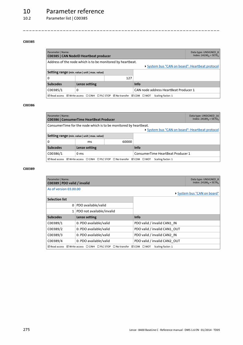
10 Parameter reference10.2 Parameter list | C00385
275 Lenze · 8400 BaseLine C · Reference manual · DMS 1.6 EN · 01/2014 · TD05
_ _ _ _ _ _ _ _ _ _ _ _ _ _ _ _ _ _ _ _ _ _ _ _ _ _ _ _ _ _ _ _ _ _ _ _ _ _ _ _ _ _ _ _ _ _ _ _ _ _ _ _ _ _ _ _ _ _ _ _ _ _ _ _
C00385
C00386
C00389
Parameter | Name:
C00385 | CAN NodeID Heartbeat producerData type: UNSIGNED_8
Index: 24190d = 5E7Eh
Address of the node which is to be monitored by heartbeat.System bus "CAN on board": Heartbeat protocol
Setting range (min. value | unit | max. value)
0 127
Subcodes Lenze setting Info
C00385/1 0 CAN node address HeartBeat Producer 1
Read access Write access CINH PLC STOP No transfer COM MOT Scaling factor: 1
Parameter | Name:
C00386 | ConsumerTime HeartBeat ProducerData type: UNSIGNED_16
Index: 24189d = 5E7Dh
ConsumerTime for the node which is to be monitored by heartbeat.System bus "CAN on board": Heartbeat protocol
Setting range (min. value | unit | max. value)
0 ms 60000
Subcodes Lenze setting Info
C00386/1 0 ms ConsumerTime HeartBeat Producer 1
Read access Write access CINH PLC STOP No transfer COM MOT Scaling factor: 1
Parameter | Name:
C00389 | PDO valid / invalidData type: UNSIGNED_8
Index: 24186d = 5E7Ah
As of version 03.00.00System bus "CAN on board"
Selection list
0 PDO available/valid
1 PDO not available/invalid
Subcodes Lenze setting Info
C00389/1 0: PDO available/valid PDO valid / invalid CAN1_IN
C00389/2 0: PDO available/valid PDO valid / invalid CAN1_OUT
C00389/3 0: PDO available/valid PDO valid / invalid CAN2_IN
C00389/4 0: PDO available/valid PDO valid / invalid CAN2_OUT
Read access Write access CINH PLC STOP No transfer COM MOT Scaling factor: 1

Lenze · 8400 BaseLine C · Reference manual · DMS 1.6 EN · 01/2014 · TD05 276
10 Parameter reference10.2 Parameter list | C00409
_ _ _ _ _ _ _ _ _ _ _ _ _ _ _ _ _ _ _ _ _ _ _ _ _ _ _ _ _ _ _ _ _ _ _ _ _ _ _ _ _ _ _ _ _ _ _ _ _ _ _ _ _ _ _ _ _ _ _ _ _ _ _ _
C00409
Parameter | Name:
C00409 | LP_CanIn MappingData type: UNSIGNED_16
Index: 24166d = 5E66h
As of version 03.00.00Mapping for port blocks LP_CanIn1 and LP_CanIn2
System bus "CAN on board": Port blocks
Setting range (min. value | unit | max. value)
0 65535
Subcodes Lenze setting Info
C00409/1 0 LP_CanIn1_wIn1(wCtrl)
C00409/2 0 LP_CanIn1_wIn2
C00409/3 0 LP_CanIn1_wIn3
C00409/4 0 LP_CanIn1_wIn4
C00409/5 0 LP_CanIn2_wIn1
C00409/6 0 LP_CanIn2_wIn2
C00409/7 0 LP_CanIn2_wIn3
C00409/8 0 LP_CanIn2_wIn4
Read access Write access CINH PLC STOP No transfer COM MOT Scaling factor: 1
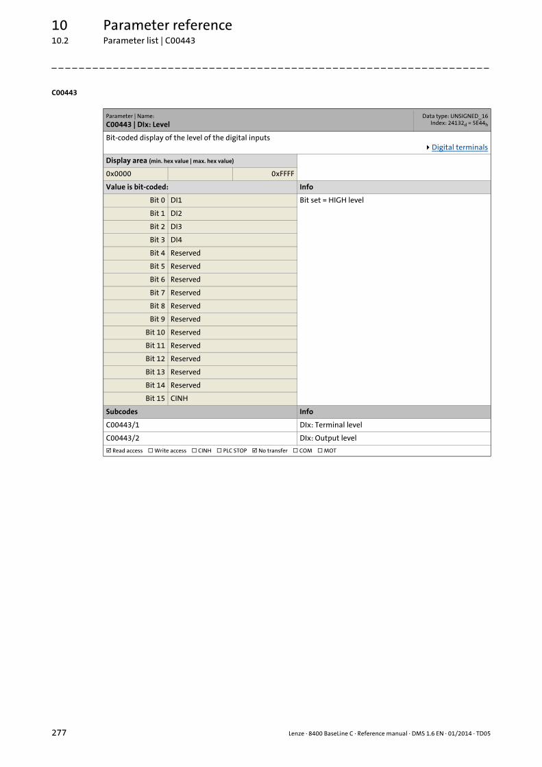
10 Parameter reference10.2 Parameter list | C00443
277 Lenze · 8400 BaseLine C · Reference manual · DMS 1.6 EN · 01/2014 · TD05
_ _ _ _ _ _ _ _ _ _ _ _ _ _ _ _ _ _ _ _ _ _ _ _ _ _ _ _ _ _ _ _ _ _ _ _ _ _ _ _ _ _ _ _ _ _ _ _ _ _ _ _ _ _ _ _ _ _ _ _ _ _ _ _
C00443
Parameter | Name:
C00443 | DIx: LevelData type: UNSIGNED_16
Index: 24132d = 5E44h
Bit-coded display of the level of the digital inputsDigital terminals
Display area (min. hex value | max. hex value)
0x0000 0xFFFF
Value is bit-coded: Info
Bit 0 DI1 Bit set = HIGH level
Bit 1 DI2
Bit 2 DI3
Bit 3 DI4
Bit 4 Reserved
Bit 5 Reserved
Bit 6 Reserved
Bit 7 Reserved
Bit 8 Reserved
Bit 9 Reserved
Bit 10 Reserved
Bit 11 Reserved
Bit 12 Reserved
Bit 13 Reserved
Bit 14 Reserved
Bit 15 CINH
Subcodes Info
C00443/1 DIx: Terminal level
C00443/2 DIx: Output level
Read access Write access CINH PLC STOP No transfer COM MOT
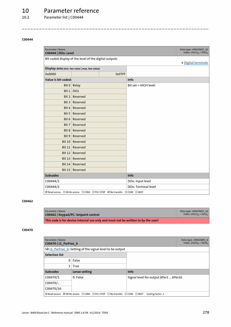
Lenze · 8400 BaseLine C · Reference manual · DMS 1.6 EN · 01/2014 · TD05 278
10 Parameter reference10.2 Parameter list | C00444
_ _ _ _ _ _ _ _ _ _ _ _ _ _ _ _ _ _ _ _ _ _ _ _ _ _ _ _ _ _ _ _ _ _ _ _ _ _ _ _ _ _ _ _ _ _ _ _ _ _ _ _ _ _ _ _ _ _ _ _ _ _ _ _
C00444
C00462
C00470
Parameter | Name:
C00444 | DOx: LevelData type: UNSIGNED_16
Index: 24131d = 5E43h
Bit-coded display of the level of the digital outputsDigital terminals
Display area (min. hex value | max. hex value)
0x0000 0xFFFF
Value is bit-coded: Info
Bit 0 Relay Bit set = HIGH level
Bit 1 DO1
Bit 2 Reserved
Bit 3 Reserved
Bit 4 Reserved
Bit 5 Reserved
Bit 6 Reserved
Bit 7 Reserved
Bit 8 Reserved
Bit 9 Reserved
Bit 10 Reserved
Bit 11 Reserved
Bit 12 Reserved
Bit 13 Reserved
Bit 14 Reserved
Bit 15 Reserved
Subcodes Info
C00444/1 DOx: Input level
C00444/2 DOx: Terminal level
Read access Write access CINH PLC STOP No transfer COM MOT
Parameter | Name:
C00462 | Keypad/PC: Setpoint controlData type: UNSIGNED_16
Index: 24113d = 5E31h
This code is for device-internal use only and must not be written to by the user!
Parameter | Name:
C00470 | LS_ParFree_bData type: UNSIGNED_8
Index: 24105d = 5E29h
SB LS_ParFree_b: Setting of the signal level to be output
Selection list
0 False
1 True
Subcodes Lenze setting Info
C00470/1 0: False Signal level for output bPar1 ... bPar16
C00470/...
C00470/16
Read access Write access CINH PLC STOP No transfer COM MOT Scaling factor: 1

10 Parameter reference10.2 Parameter list | C00472
279 Lenze · 8400 BaseLine C · Reference manual · DMS 1.6 EN · 01/2014 · TD05
_ _ _ _ _ _ _ _ _ _ _ _ _ _ _ _ _ _ _ _ _ _ _ _ _ _ _ _ _ _ _ _ _ _ _ _ _ _ _ _ _ _ _ _ _ _ _ _ _ _ _ _ _ _ _ _ _ _ _ _ _ _ _ _
C00472
C00480
C00481
Parameter | Name:
C00472 | LS_ParFree_aData type: INTEGER_16Index: 24103d = 5E27h
SB LS_ParFree_a: Setting of the analog signals to be output
Setting range (min. value | unit | max. value)
-199.9 % 199.9
Subcodes Lenze setting Info
C00472/1 0.0 % Value for output nPar1_a
C00472/2 0.0 % Value for output nPar2_a
C00472/3 100.0 % Value for output nPar3_a
C00472/4 100.0 % Value for output nPar4_a
Read access Write access CINH PLC STOP No transfer COM MOT Scaling factor: 100
Parameter | Name:
C00480 | LS_DisFree_bData type: UNSIGNED_8
Index: 24095d = 5E1Fh
SB LS_DisFree_b: Display of the input values
Display area (min. hex value | max. hex value)
0x00 0xFF
Value is bit-coded: Info
Bit 0 bDis1 Signal level input bDis1 ... bDis8
... ...
Bit 7 bDis8
Read access Write access CINH PLC STOP No transfer COM MOT
Parameter | Name:
C00481 | LS_DisFreeData type: UNSIGNED_16
Index: 24094d = 5E1Eh
SB LS_DisFree: Display of the input values
Display area (min. hex value | max. hex value)
0x0000 0xFFFF
Value is bit-coded:
Bit 0 Bit0
... ...
Bit 15 Bit15
Subcodes Info
C00481/1 Input values wDis1 ... wDis4
C00481/...
C00481/4
Read access Write access CINH PLC STOP No transfer COM MOT
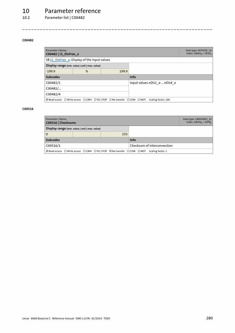
Lenze · 8400 BaseLine C · Reference manual · DMS 1.6 EN · 01/2014 · TD05 280
10 Parameter reference10.2 Parameter list | C00482
_ _ _ _ _ _ _ _ _ _ _ _ _ _ _ _ _ _ _ _ _ _ _ _ _ _ _ _ _ _ _ _ _ _ _ _ _ _ _ _ _ _ _ _ _ _ _ _ _ _ _ _ _ _ _ _ _ _ _ _ _ _ _ _
C00482
C00516
Parameter | Name:
C00482 | LS_DisFree_aData type: INTEGER_16Index: 24093d = 5E1Dh
SB LS_DisFree_a: Display of the input values
Display range (min. value | unit | max. value)
-199.9 % 199.9
Subcodes Info
C00482/1 Input values nDis1_a ... nDis4_a
C00482/...
C00482/4
Read access Write access CINH PLC STOP No transfer COM MOT Scaling factor: 100
Parameter | Name:
C00516 | ChecksumsData type: UNSIGNED_32
Index: 24059d = 5DFBh
Display range (min. value | unit | max. value)
0 255
Subcodes Info
C00516/1 Checksum of interconnection
Read access Write access CINH PLC STOP No transfer COM MOT Scaling factor: 1

10 Parameter reference10.2 Parameter list | C00517
281 Lenze · 8400 BaseLine C · Reference manual · DMS 1.6 EN · 01/2014 · TD05
_ _ _ _ _ _ _ _ _ _ _ _ _ _ _ _ _ _ _ _ _ _ _ _ _ _ _ _ _ _ _ _ _ _ _ _ _ _ _ _ _ _ _ _ _ _ _ _ _ _ _ _ _ _ _ _ _ _ _ _ _ _ _ _
C00517
C00565
Parameter | Name:
C00517 | User menuData type: INTEGER_32Index: 24058d = 5DFAh
When a system is installed, parameters must be changed time and again until the system runs satisfactorily. The user menu of a device serves to create a selection of frequently used parameters to be able to access and change these parameters quickly.
• For setting "0" no entry is displayed in the user menu.
Setting range (min. value | unit | max. value)
0 994
Subcodes Lenze setting Info
C00517/1 51 C00051: Display of actual speed value
C00517/2 53 C00053: Display of DC-bus voltage
C00517/3 54 C00054: Display of motor current
C00517/4 61 C00061: Display of heatsink temperature
C00517/5 137 C00137: Display of device state
C00517/6 0 User menu: entry 6
C00517/7 0 User menu: entry 7
C00517/8 11 C00011: Reference speed
C00517/9 39 C00039/1: Fixed setpoint 1C00039/2: Fixed setpoint 2C00039/3: Fixed setpoint 3
C00517/10 0 User menu: entry 10
C00517/11 12 C00012: Acceleration time main setpoint
C00517/12 13 C00013: Deceleration time main setpoint
C00517/13 15 C00015: V/f base frequency
C00517/14 16 C00016: Vmin boost
C00517/15 22 C00022: Imax in motor mode
C00517/16 120 C00120: Motor overload threshold (I2xt)
C00517/17 87 C00087: Rated motor speed
C00517/18 99 C00099: Display of firmware version
C00517/19 0 User menu: entry 19
C00517/20 0 User menu: entry 20
Read access Write access CINH PLC STOP No transfer COM MOT Scaling factor: 1
Parameter | Name:
C00565 | Resp. to mains phase failureData type: UNSIGNED_8
Index: 24010d = 5DCAh
Response to the failure of mains phases
Selection list (Lenze setting printed in bold)
0 No Reaction
1 Fault
4 WarningLocked
Read access Write access CINH PLC STOP No transfer COM MOT Scaling factor: 1

Lenze · 8400 BaseLine C · Reference manual · DMS 1.6 EN · 01/2014 · TD05 282
10 Parameter reference10.2 Parameter list | C00574
_ _ _ _ _ _ _ _ _ _ _ _ _ _ _ _ _ _ _ _ _ _ _ _ _ _ _ _ _ _ _ _ _ _ _ _ _ _ _ _ _ _ _ _ _ _ _ _ _ _ _ _ _ _ _ _ _ _ _ _ _ _ _ _
C00574
C00581
C00592
Parameter | Name:
C00574 | Resp. to brake resist. overtemp.Data type: UNSIGNED_8
Index: 24001d = 5DC1h
Response when the permanently set threshold for monitoring the brake resistor utilisation has been reached.
Selection list (Lenze setting printed in bold)
0 No Reaction
1 Fault
4 WarningLocked
Read access Write access CINH PLC STOP No transfer COM MOT Scaling factor: 1
Parameter | Name:
C00581 | Resp. to LS_SetError_xData type: UNSIGNED_8
Index: 23994d = 5DBAh
Selection of the error responses for application error messages• An application error message is tripped by a FALSE-TRUE edge at the binary inputs bSetError1...2.
Selection list
0 No Reaction
1 Fault
2 Trouble
4 WarningLocked
Subcodes Lenze setting Info
C00581/1 1: Fault LS_SetError_1: Resp. bSetError1
C00581/2 1: Fault LS_SetError_1: Resp. bSetError2
Read access Write access CINH PLC STOP No transfer COM MOT Scaling factor: 1
Parameter | Name:
C00592 | Resp. to CAN bus connectionData type: UNSIGNED_8
Index: 23983d = 5DAFh
Configuration of monitoring of the CAN interface (group 1)System bus "CAN on board"
Selection list
0 No Reaction
1 Fault
2 Trouble
4 WarningLocked
Subcodes Lenze setting Info
C00592/1 0: No Reaction Response to incorrect telegram for CAN communication
C00592/2 0: No Reaction Response to "BusOff" (bus system switched off)
C00592/3 0: No Reaction Response to warnings of the CAN controller
C00592/4 0: No Reaction Response to communication stop of a CAN bus node
C00592/5 0: No Reaction Response to an event in the case of monitoring via heart-beat protocol
Read access Write access CINH PLC STOP No transfer COM MOT Scaling factor: 1

10 Parameter reference10.2 Parameter list | C00593
283 Lenze · 8400 BaseLine C · Reference manual · DMS 1.6 EN · 01/2014 · TD05
_ _ _ _ _ _ _ _ _ _ _ _ _ _ _ _ _ _ _ _ _ _ _ _ _ _ _ _ _ _ _ _ _ _ _ _ _ _ _ _ _ _ _ _ _ _ _ _ _ _ _ _ _ _ _ _ _ _ _ _ _ _ _ _
C00593
C00594
C00598
Parameter | Name:
C00593 | Resp. to CANx_IN monitoringData type: UNSIGNED_8
Index: 23982d = 5DAEh
Configuration of monitoring of the CAN interface (group 2)System bus "CAN on board"
Selection list
0 No Reaction
1 Fault
2 Trouble
4 WarningLocked
Subcodes Lenze setting Info
C00593/1 0: No Reaction Response if the monitoring time set in C00357/1 for the reception of the PDO CAN1_IN is exceeded.
C00593/2 0: No Reaction Response if the monitoring time set in C00357/2 for the reception of the PDO CAN2_IN is exceeded.
Read access Write access CINH PLC STOP No transfer COM MOT Scaling factor: 1
Parameter | Name:
C00594 | Resp. to control word errorData type: UNSIGNED_8
Index: 23981d = 5DADh
As of version 03.00.00Configuration of monitoring of the device control
Selection list
0 No Reaction
1 Fault
2 Trouble
4 WarningLocked
Subcodes Lenze setting Info
C00594/1 1: Fault Response if error bit 14 in the CAN control word is set.
Read access Write access CINH PLC STOP No transfer COM MOT Scaling factor: 1
Parameter | Name:
C00598 | Resp. to open circuit AINxData type: UNSIGNED_8
Index: 23977d = 5DA9h
Configuration of monitoring the analog inputAnalog terminals
Selection list
0 No Reaction
1 Fault
2 Trouble
4 WarningLocked
Subcodes Lenze setting Info
C00598/1 1: Fault Response to open circuit at AIN1 when being configured as 4 ... 20 mA-current loop
Read access Write access CINH PLC STOP No transfer COM MOT Scaling factor: 1

Lenze · 8400 BaseLine C · Reference manual · DMS 1.6 EN · 01/2014 · TD05 284
10 Parameter reference10.2 Parameter list | C00600
_ _ _ _ _ _ _ _ _ _ _ _ _ _ _ _ _ _ _ _ _ _ _ _ _ _ _ _ _ _ _ _ _ _ _ _ _ _ _ _ _ _ _ _ _ _ _ _ _ _ _ _ _ _ _ _ _ _ _ _ _ _ _ _
C00600
C00601
C00604
C00606
Parameter | Name:
C00600 | Resp. to DC bus undervoltageData type: UNSIGNED_8
Index: 23975d = 5DA7h
Configuration of monitoring of the motor control (group 3)
Selection list
1 Fault
2 Trouble
Subcodes Lenze setting Info
C00600/1 2: Trouble Response to undervoltage in the DC bus
Read access Write access CINH PLC STOP No transfer COM MOT Scaling factor: 1
Parameter | Name:
C00601 | Del. resp.to fault: DC bus overvoltageData type: UNSIGNED_16
Index: 23974d = 5DA6h
Delay times for error responses
Setting range (min. value | unit | max. value)
0.00 s 65.00
Subcodes Lenze setting Info
C00601/1 2.00 s Delay time for error activation "DC-bus overvoltage"• In case of DC-bus overvoltage, an error is only trans-
mitted after this delay time has elapsed.
Read access Write access CINH PLC STOP No transfer COM MOT Scaling factor: 1000
Parameter | Name:
C00604 | Resp. to device overload (Ixt)Data type: UNSIGNED_8
Index: 23971d = 5DA3h
Response if the adjustable device utilisation threshold (C00123) is reached.• The current device utilisation is displayed in C00064.
Selection list (Lenze setting printed in bold)
0 No Reaction
1 Fault
4 WarningLocked
Read access Write access CINH PLC STOP No transfer COM MOT Scaling factor: 1
Parameter | Name:
C00606 | Resp. to motor overload (I²xt)Data type: UNSIGNED_8
Index: 23969d = 5DA1h
Response if the adjustable motor overload threshold (C00120) is reached.• The current thermal motor load is displayed in C00066.
Selection list (Lenze setting printed in bold)
0 No Reaction
1 Fault
4 WarningLocked
Read access Write access CINH PLC STOP No transfer COM MOT Scaling factor: 1

10 Parameter reference10.2 Parameter list | C00620
285 Lenze · 8400 BaseLine C · Reference manual · DMS 1.6 EN · 01/2014 · TD05
_ _ _ _ _ _ _ _ _ _ _ _ _ _ _ _ _ _ _ _ _ _ _ _ _ _ _ _ _ _ _ _ _ _ _ _ _ _ _ _ _ _ _ _ _ _ _ _ _ _ _ _ _ _ _ _ _ _ _ _ _ _ _ _
C00620
Parameter | Name:
C00620 | 16-bit system connectionData type: UNSIGNED_16
Index: 23955d = 5D93h
Connection parameters: 16-bit inputs• Selection of the 16-bit output signals for connection with the 16-bit input signals.• The selection list contains all 16-bit output signals which can be assigned to the 16-bit inputs mapped by the
subcodes.
Selection list
See selection list - analog signals
Subcodes Lenze setting Info
C00620/1 0: Not connected Reserved
C00620/2 0: Not connected Reserved
C00620/3 0: Not connected Reserved
C00620/4 0: Not connected Reserved
C00620/5 0: Not connected LS_DisFree:wDis1
C00620/6 0: Not connected LS_DisFree:wDis2
C00620/7 0: Not connected LS_DisFree:wDis3
C00620/8 0: Not connected LS_DisFree:wDis4
C00620/9 0: Not connected LS_DisFree_a:nDis1_a
C00620/10 0: Not connected LS_DisFree_a:nDis2_a
C00620/11 0: Not connected LS_DisFree_a:nDis3_a
C00620/12 0: Not connected LS_DisFree_a:nDis4_a
C00620/13 0: Not connected Reserved
C00620/14 0: Not connected Reserved
C00620/15 0: Not connected Reserved
C00620/16 0: Not connected Reserved
C00620/17 0: Not connected Reserved
C00620/18 0: Not connected Reserved
C00620/19 0: Not connected Reserved
C00620/20 0: Not connected LP_CanOut1: wState
C00620/21 0: Not connected LP_CanOut1: wOut2
C00620/22 0: Not connected LP_CanOut1: wOut3
C00620/23 0: Not connected LP_CanOut1: wOut4
C00620/24 0: Not connected LP_CanOut2: wOut1
C00620/25 0: Not connected LP_CanOut2: wOut2
C00620/26 0: Not connected LP_CanOut2: wOut3
C00620/27 0: Not connected LP_CanOut2: wOut4
Read access Write access CINH PLC STOP No transfer COM MOT Scaling factor: 1
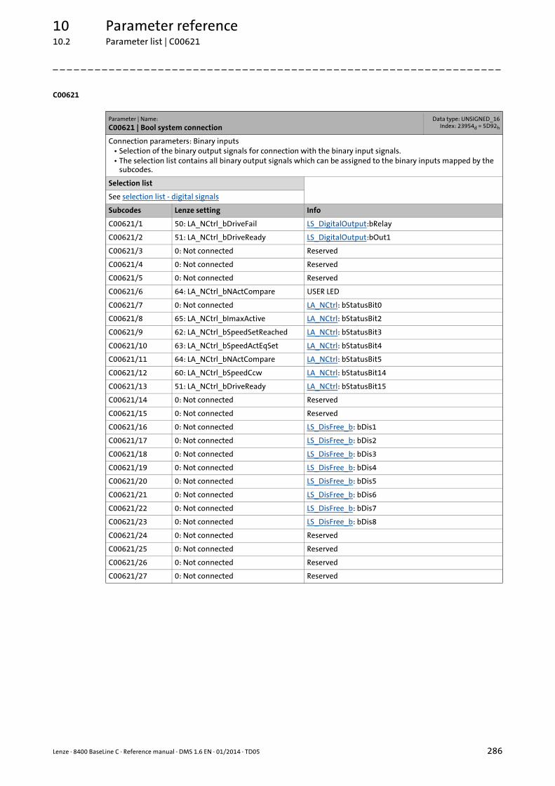
Lenze · 8400 BaseLine C · Reference manual · DMS 1.6 EN · 01/2014 · TD05 286
10 Parameter reference10.2 Parameter list | C00621
_ _ _ _ _ _ _ _ _ _ _ _ _ _ _ _ _ _ _ _ _ _ _ _ _ _ _ _ _ _ _ _ _ _ _ _ _ _ _ _ _ _ _ _ _ _ _ _ _ _ _ _ _ _ _ _ _ _ _ _ _ _ _ _
C00621
Parameter | Name:
C00621 | Bool system connectionData type: UNSIGNED_16
Index: 23954d = 5D92h
Connection parameters: Binary inputs• Selection of the binary output signals for connection with the binary input signals.• The selection list contains all binary output signals which can be assigned to the binary inputs mapped by the
subcodes.
Selection list
See selection list - digital signals
Subcodes Lenze setting Info
C00621/1 50: LA_NCtrl_bDriveFail LS_DigitalOutput:bRelay
C00621/2 51: LA_NCtrl_bDriveReady LS_DigitalOutput:bOut1
C00621/3 0: Not connected Reserved
C00621/4 0: Not connected Reserved
C00621/5 0: Not connected Reserved
C00621/6 64: LA_NCtrl_bNActCompare USER LED
C00621/7 0: Not connected LA_NCtrl: bStatusBit0
C00621/8 65: LA_NCtrl_bImaxActive LA_NCtrl: bStatusBit2
C00621/9 62: LA_NCtrl_bSpeedSetReached LA_NCtrl: bStatusBit3
C00621/10 63: LA_NCtrl_bSpeedActEqSet LA_NCtrl: bStatusBit4
C00621/11 64: LA_NCtrl_bNActCompare LA_NCtrl: bStatusBit5
C00621/12 60: LA_NCtrl_bSpeedCcw LA_NCtrl: bStatusBit14
C00621/13 51: LA_NCtrl_bDriveReady LA_NCtrl: bStatusBit15
C00621/14 0: Not connected Reserved
C00621/15 0: Not connected Reserved
C00621/16 0: Not connected LS_DisFree_b: bDis1
C00621/17 0: Not connected LS_DisFree_b: bDis2
C00621/18 0: Not connected LS_DisFree_b: bDis3
C00621/19 0: Not connected LS_DisFree_b: bDis4
C00621/20 0: Not connected LS_DisFree_b: bDis5
C00621/21 0: Not connected LS_DisFree_b: bDis6
C00621/22 0: Not connected LS_DisFree_b: bDis7
C00621/23 0: Not connected LS_DisFree_b: bDis8
C00621/24 0: Not connected Reserved
C00621/25 0: Not connected Reserved
C00621/26 0: Not connected Reserved
C00621/27 0: Not connected Reserved
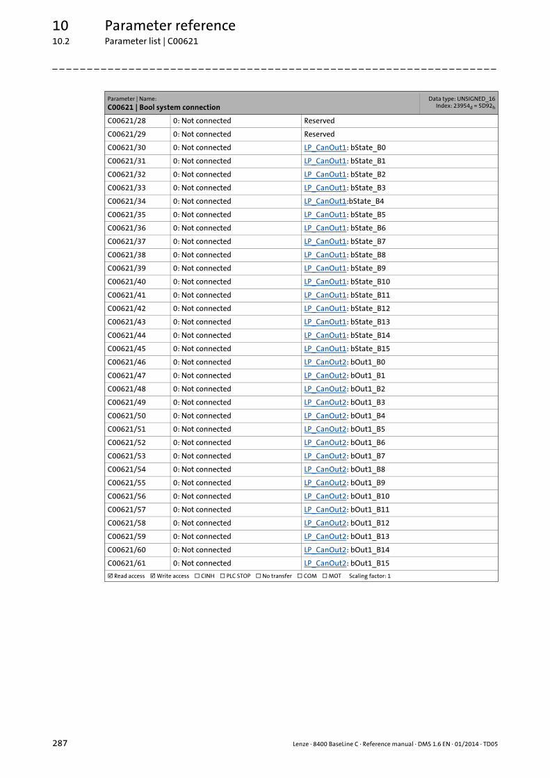
10 Parameter reference10.2 Parameter list | C00621
287 Lenze · 8400 BaseLine C · Reference manual · DMS 1.6 EN · 01/2014 · TD05
_ _ _ _ _ _ _ _ _ _ _ _ _ _ _ _ _ _ _ _ _ _ _ _ _ _ _ _ _ _ _ _ _ _ _ _ _ _ _ _ _ _ _ _ _ _ _ _ _ _ _ _ _ _ _ _ _ _ _ _ _ _ _ _
C00621/28 0: Not connected Reserved
C00621/29 0: Not connected Reserved
C00621/30 0: Not connected LP_CanOut1: bState_B0
C00621/31 0: Not connected LP_CanOut1: bState_B1
C00621/32 0: Not connected LP_CanOut1: bState_B2
C00621/33 0: Not connected LP_CanOut1: bState_B3
C00621/34 0: Not connected LP_CanOut1:bState_B4
C00621/35 0: Not connected LP_CanOut1: bState_B5
C00621/36 0: Not connected LP_CanOut1: bState_B6
C00621/37 0: Not connected LP_CanOut1: bState_B7
C00621/38 0: Not connected LP_CanOut1: bState_B8
C00621/39 0: Not connected LP_CanOut1: bState_B9
C00621/40 0: Not connected LP_CanOut1: bState_B10
C00621/41 0: Not connected LP_CanOut1: bState_B11
C00621/42 0: Not connected LP_CanOut1: bState_B12
C00621/43 0: Not connected LP_CanOut1: bState_B13
C00621/44 0: Not connected LP_CanOut1: bState_B14
C00621/45 0: Not connected LP_CanOut1: bState_B15
C00621/46 0: Not connected LP_CanOut2: bOut1_B0
C00621/47 0: Not connected LP_CanOut2: bOut1_B1
C00621/48 0: Not connected LP_CanOut2: bOut1_B2
C00621/49 0: Not connected LP_CanOut2: bOut1_B3
C00621/50 0: Not connected LP_CanOut2: bOut1_B4
C00621/51 0: Not connected LP_CanOut2: bOut1_B5
C00621/52 0: Not connected LP_CanOut2: bOut1_B6
C00621/53 0: Not connected LP_CanOut2: bOut1_B7
C00621/54 0: Not connected LP_CanOut2: bOut1_B8
C00621/55 0: Not connected LP_CanOut2: bOut1_B9
C00621/56 0: Not connected LP_CanOut2: bOut1_B10
C00621/57 0: Not connected LP_CanOut2: bOut1_B11
C00621/58 0: Not connected LP_CanOut2: bOut1_B12
C00621/59 0: Not connected LP_CanOut2: bOut1_B13
C00621/60 0: Not connected LP_CanOut2: bOut1_B14
C00621/61 0: Not connected LP_CanOut2: bOut1_B15
Read access Write access CINH PLC STOP No transfer COM MOT Scaling factor: 1
Parameter | Name:
C00621 | Bool system connectionData type: UNSIGNED_16
Index: 23954d = 5D92h
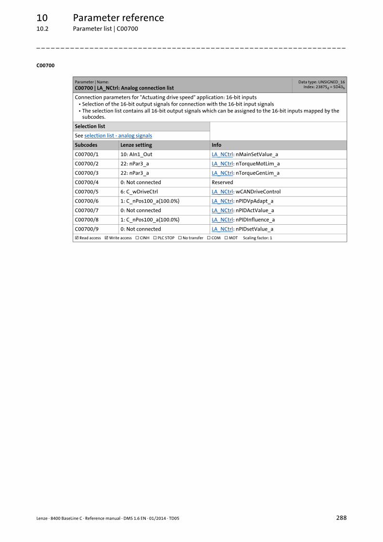
Lenze · 8400 BaseLine C · Reference manual · DMS 1.6 EN · 01/2014 · TD05 288
10 Parameter reference10.2 Parameter list | C00700
_ _ _ _ _ _ _ _ _ _ _ _ _ _ _ _ _ _ _ _ _ _ _ _ _ _ _ _ _ _ _ _ _ _ _ _ _ _ _ _ _ _ _ _ _ _ _ _ _ _ _ _ _ _ _ _ _ _ _ _ _ _ _ _
C00700
Parameter | Name:
C00700 | LA_NCtrl: Analog connection listData type: UNSIGNED_16
Index: 23875d = 5D43h
Connection parameters for "Actuating drive speed" application: 16-bit inputs• Selection of the 16-bit output signals for connection with the 16-bit input signals• The selection list contains all 16-bit output signals which can be assigned to the 16-bit inputs mapped by the
subcodes.
Selection list
See selection list - analog signals
Subcodes Lenze setting Info
C00700/1 10: AIn1_Out LA_NCtrl: nMainSetValue_a
C00700/2 22: nPar3_a LA_NCtrl: nTorqueMotLim_a
C00700/3 22: nPar3_a LA_NCtrl: nTorqueGenLim_a
C00700/4 0: Not connected Reserved
C00700/5 6: C_wDriveCtrl LA_NCtrl: wCANDriveControl
C00700/6 1: C_nPos100_a(100.0%) LA_NCtrl: nPIDVpAdapt_a
C00700/7 0: Not connected LA_NCtrl: nPIDActValue_a
C00700/8 1: C_nPos100_a(100.0%) LA_NCtrl: nPIDInfluence_a
C00700/9 0: Not connected LA_NCtrl: nPIDsetValue_a
Read access Write access CINH PLC STOP No transfer COM MOT Scaling factor: 1

10 Parameter reference10.2 Parameter list | C00701
289 Lenze · 8400 BaseLine C · Reference manual · DMS 1.6 EN · 01/2014 · TD05
_ _ _ _ _ _ _ _ _ _ _ _ _ _ _ _ _ _ _ _ _ _ _ _ _ _ _ _ _ _ _ _ _ _ _ _ _ _ _ _ _ _ _ _ _ _ _ _ _ _ _ _ _ _ _ _ _ _ _ _ _ _ _ _
C00701
C00725
Parameter | Name:
C00701 | LA_NCtrl: digital connection listData type: UNSIGNED_16
Index: 23874d = 5D42h
Connection parameters for "Actuating drive speed" application: Binary inputs• Selection of the binary output signals for connection with the binary input signals• The selection list contains all binary output signals which can be assigned to the binary inputs mapped by the
subcodes.
Selection list
See selection list - digital signals
Subcodes Lenze setting Info
C00701/1 0: Not connected LA_NCtrl: bCInh
C00701/2 15: DigIn_CInh LA_NCtrl: bFailReset
C00701/3 0: Not connected LA_NCtrl: bSetQuickstop
C00701/4 13: DigIn_bIn3 LA_NCtrl: bSetDCBrake
C00701/5 14: DigIn_bIn4 LA_NCtrl: bSetSpeedCcw
C00701/6 11: DigIn_bIn1 LA_NCtrl: bJogSpeed1
C00701/7 12: DigIn_bIn2 LA_NCtrl: bJogSpeed2
C00701/8 0: Not connected LA_NCtrl: bMPotUp
C00701/9 0: Not connected LA_NCtrl: bMPotDown
C00701/10 0: Not connected LA_NCtrl: bMPotInAct
C00701/11 0: Not connected LA_NCtrl: bMPotEnable
C00701/12 0: Not connected LA_NCtrl: bRFG_0
C00701/13 0: Not connected LA_NCtrl: bSetError1
C00701/14 0: Not connected LA_NCtrl: bSetError2
C00701/15 1: C_bTrue LA_NCtrl: bPIDInfluenceRamp
C00701/16 0: Not connected LA_NCtrl: bPIDIOff
C00701/17 1: C_bTrue LA_NCtrl: bRLQCw
C00701/18 0: Not connected LA_NCtrl: bRLQCcw
Read access Write access CINH PLC STOP No transfer COM MOT Scaling factor: 1
Parameter | Name:
C00725 | Current switching frequencyData type: UNSIGNED_8
Index: 23850d = 5D2Ah
Display of the current switching frequency• When a variable switching frequency is selected in C00018, the switching frequency may change as a function
of the load and rotational frequency.
Selection list (read only)
1 4 kHz var./drive-optimised
2 8 kHz var./drive-optimised
3 16 kHz var./drive-optimised
5 2 kHz constant/drive-optimised
6 4 kHz constant/drive-optimised
7 8 kHz constant/drive-optimised
8 16 kHz constant/drive-optimised
Read access Write access CINH PLC STOP No transfer COM MOT Scaling factor: 1

Lenze · 8400 BaseLine C · Reference manual · DMS 1.6 EN · 01/2014 · TD05 290
10 Parameter reference10.2 Parameter list | C00727
_ _ _ _ _ _ _ _ _ _ _ _ _ _ _ _ _ _ _ _ _ _ _ _ _ _ _ _ _ _ _ _ _ _ _ _ _ _ _ _ _ _ _ _ _ _ _ _ _ _ _ _ _ _ _ _ _ _ _ _ _ _ _ _
C00727
C00728
C00729
C00800
C00801
Parameter | Name:
C00727 | LS_Keypad: Digital valuesData type: UNSIGNED_8
Index: 23848d = 5D28h
Executing control commands when operating via keypad
Setting range (min. value | unit | max. value)
0 1
Subcodes Lenze setting Info
C00727/1 0 "1" ≡ request quick stop
C00727/2 0 "1" ≡ request DC-injection braking
C00727/3 0 "1" ≡ request change of direction of rotation
C00727/4 0 "1" ≡ request fixed speed setpoint 1
C00727/5 0 "1" ≡ request fixed speed setpoint 2
Read access Write access CINH PLC STOP No transfer COM MOT Scaling factor: 1
Parameter | Name:
C00728 | LS_Keypad: Keypad analog valuesData type: INTEGER_16Index: 23847d = 5D27h
Selection of different setpoints when operating via keypad
Setting range (min. value | unit | max. value)
-199.9 % 199.9
Subcodes Lenze setting Info
C00728/1 100.0 % Torque limit in motor mode
C00728/2 100.0 % Torque limit in generator mode
C00728/3 0.0 % Setpoint speed
Read access Write access CINH PLC STOP No transfer COM MOT Scaling factor: 100
Parameter | Name:
C00729 | Keypad/PC: Speed setpointData type: INTEGER_16Index: 23846d = 5D26h
This code is for device-internal use only and must not be written to by the user!
Parameter | Name:
C00800 | L_MPot_1: Upper limitData type: INTEGER_16Index: 23775d = 5CDFh
FB L_MPot_1: Upper limit of the motor potentiometer function
Setting range (min. value | unit | max. value) Lenze setting
-199.9 % 199.9 100.0 %
Read access Write access CINH PLC STOP No transfer COM MOT Scaling factor: 100
Parameter | Name:
C00801 | L_MPot_1: Lower limitData type: INTEGER_16Index: 23774d = 5CDEh
FB L_MPot_1: Lower limit of the motor potentiometer function
Setting range (min. value | unit | max. value) Lenze setting
-199.9 % 199.9 -100.0 %
Read access Write access CINH PLC STOP No transfer COM MOT Scaling factor: 100

10 Parameter reference10.2 Parameter list | C00802
291 Lenze · 8400 BaseLine C · Reference manual · DMS 1.6 EN · 01/2014 · TD05
_ _ _ _ _ _ _ _ _ _ _ _ _ _ _ _ _ _ _ _ _ _ _ _ _ _ _ _ _ _ _ _ _ _ _ _ _ _ _ _ _ _ _ _ _ _ _ _ _ _ _ _ _ _ _ _ _ _ _ _ _ _ _ _
C00802
C00803
C00804
C00805
Parameter | Name:
C00802 | L_MPot_1: Acceleration timeData type: UNSIGNED_16
Index: 23773d = 5CDDh
FB L_MPot_1: Acceleration time of the motor potentiometer function
Setting range (min. value | unit | max. value) Lenze setting
0.1 s 999.9 10.0 s
Read access Write access CINH PLC STOP No transfer COM MOT Scaling factor: 10
Parameter | Name:
C00803 | L_MPot_1: Deceleration timeData type: UNSIGNED_16
Index: 23772d = 5CDCh
FB L_MPot_1: Deceleration time of the motor potentiometer function
Setting range (min. value | unit | max. value) Lenze setting
0.1 s 999.9 10.0 s
Read access Write access CINH PLC STOP No transfer COM MOT Scaling factor: 10
Parameter | Name:
C00804 | L_MPot_1: Inactive fct.Data type: UNSIGNED_8
Index: 23771d = 5CDBh
FB L_MPot_1: Selection of the response when deactivating the motor potentiometer via the bInAct input
Selection list (Lenze setting printed in bold) Info
0 Keep value Keep output value
1 Deceleration to 0 Deceleration via ramp to 0
2 Deceleration to lower limit Deceleration via ramp to lower limit (C00801)
3 Without ramp to 0 Jump to 0
4 Without ramp to lower limit Jump to lower limit (C00800)
5 Acceleration to upper limit Acceleration via ramp to upper limit (C00800)
Read access Write access CINH PLC STOP No transfer COM MOT Scaling factor: 1
Parameter | Name:
C00805 | L_MPot_1: Init fct.Data type: UNSIGNED_8
Index: 23770d = 5CDAh
FB L_MPot_1: Selection of the response when switching on the device
Selection list (Lenze setting printed in bold)
0 Load last value
1 Load lower limit
2 Load 0
Read access Write access CINH PLC STOP No transfer COM MOT Scaling factor: 1

Lenze · 8400 BaseLine C · Reference manual · DMS 1.6 EN · 01/2014 · TD05 292
10 Parameter reference10.2 Parameter list | C00806
_ _ _ _ _ _ _ _ _ _ _ _ _ _ _ _ _ _ _ _ _ _ _ _ _ _ _ _ _ _ _ _ _ _ _ _ _ _ _ _ _ _ _ _ _ _ _ _ _ _ _ _ _ _ _ _ _ _ _ _ _ _ _ _
C00806
C00830
C00831
Parameter | Name:
C00806 | L_MPot_1: UseData type: UNSIGNED_8
Index: 23769d = 5CD9h
FB L_MPot_1: Use of the motor potentiometer
Selection list (Lenze setting printed in bold) Info
0 No The motor potentiometer is not used.• The analog value applied to the nIn_a input is looped
through without any changes to the nOut_a output.
1 Yes The motor potentiometer is used.• The analog value applied at the nIn_a input is led via
the motor potentiometer and provided at the nOut_a output.
Read access Write access CINH PLC STOP No transfer COM MOT Scaling factor: 1
Parameter | Name:
C00830 | 16-bit analogue inputData type: INTEGER_16Index: 23745d = 5CC1h
Display in percent of 16-bit input values of different blocks
Display range (min. value | unit | max. value)
-199.9 % 199.9
Subcodes Info
C00830/1 L_NSet_1: nNSet_a
C00830/2 L_NSet_1: nOut_a
C00830/3 LS_MCTRL: nSpeedSetValue_a
C00830/4 LS_MCTRL: nTorqueMotLimit_a
C00830/5 LS_MCTRL: nTorqueGenLimit_a
C00830/6 L_PCTRL_1: nAct_a
C00830/7 L_PCTRL_1: nAdapt_a
C00830/8 L_PCTRL_1: nSet_a
C00830/9 L_PCTRL_1: nInflu_a
C00830/10 L_PCTRL_1: nNSet_a
C00830/11 L_MPot_1: nIn_a
Read access Write access CINH PLC STOP No transfer COM MOT Scaling factor: 100
Parameter | Name:
C00831 | 16-bit common inputData type: UNSIGNED_16
Index: 23744d = 5CC0h
Decimal/hexadecimal/bit-coded display of 16-bit input values of different blocks
Display area (min. hex value | max. hex value)
0x0000 0xFFFF
Value is bit-coded:
Bit 0 Bit0
... ...
Bit 15 Bit15
Subcodes Info
C00831/1 LS_DCTRL: wCANControl
Read access Write access CINH PLC STOP No transfer COM MOT

10 Parameter reference10.2 Parameter list | C00833
293 Lenze · 8400 BaseLine C · Reference manual · DMS 1.6 EN · 01/2014 · TD05
_ _ _ _ _ _ _ _ _ _ _ _ _ _ _ _ _ _ _ _ _ _ _ _ _ _ _ _ _ _ _ _ _ _ _ _ _ _ _ _ _ _ _ _ _ _ _ _ _ _ _ _ _ _ _ _ _ _ _ _ _ _ _ _
C00833
Parameter | Name:
C00833 | 8-bit inputData type: UNSIGNED_8
Index: 23742d = 5CBEh
Display of the signal status of the binary inputs of different blocks
Selection list
0 False
1 True
Subcodes Info
C00833/1 L_NSet_1: bRfg0
C00833/2 L_NSet_1: bNSetInv
C00833/3 L_NSet_1: bJog1
C00833/4 L_NSet_1: bJog2
C00833/5 LS_SetError_1: bSetError1
C00833/6 LS_SetError_1: bSetError2
C00833/7 L_MPot_1: bUp
C00833/8 L_MPot_1: bInAct
C00833/9 L_MPot_1: bDown
C00833/10 L_MPot_1: bEnable
C00833/11 Reserved
C00833/12 L_PCTRL_1: bIOff
C00833/13 L_PCTRL_1: bEnableInfluenceRamp
C00833/14 LS_DCTRL: bCINH
C00833/15 LS_DCTRL: bFailReset
C00833/16 LS_DCTRL: bStatus_B0
C00833/17 LS_DCTRL: bStatus_B2
C00833/18 LS_DCTRL: bStatus_B3
C00833/19 LS_DCTRL: bStatus_B4
C00833/20 LS_DCTRL: bStatus_B5
C00833/21 LS_DCTRL: bStatus_B14
C00833/22 LS_DCTRL: bStatus_B15
C00833/23 L_RLQ_1: bCw
C00833/24 L_RLQ_1: bCcw
Read access Write access CINH PLC STOP No transfer COM MOT Scaling factor: 1
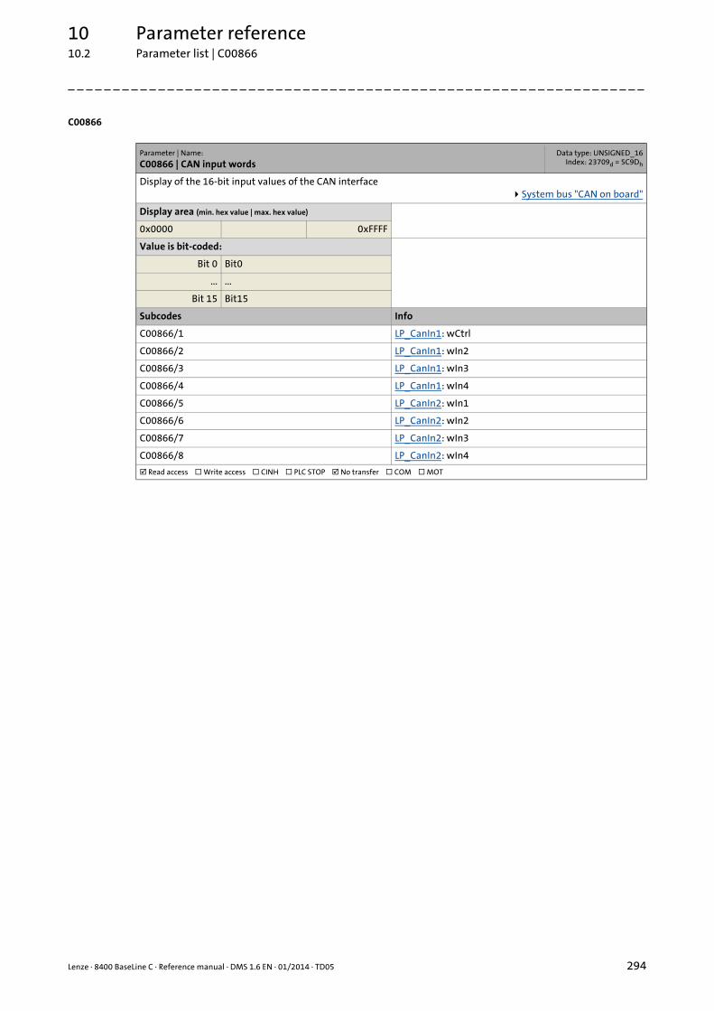
Lenze · 8400 BaseLine C · Reference manual · DMS 1.6 EN · 01/2014 · TD05 294
10 Parameter reference10.2 Parameter list | C00866
_ _ _ _ _ _ _ _ _ _ _ _ _ _ _ _ _ _ _ _ _ _ _ _ _ _ _ _ _ _ _ _ _ _ _ _ _ _ _ _ _ _ _ _ _ _ _ _ _ _ _ _ _ _ _ _ _ _ _ _ _ _ _ _
C00866
Parameter | Name:
C00866 | CAN input wordsData type: UNSIGNED_16
Index: 23709d = 5C9Dh
Display of the 16-bit input values of the CAN interfaceSystem bus "CAN on board"
Display area (min. hex value | max. hex value)
0x0000 0xFFFF
Value is bit-coded:
Bit 0 Bit0
... ...
Bit 15 Bit15
Subcodes Info
C00866/1 LP_CanIn1: wCtrl
C00866/2 LP_CanIn1: wIn2
C00866/3 LP_CanIn1: wIn3
C00866/4 LP_CanIn1: wIn4
C00866/5 LP_CanIn2: wIn1
C00866/6 LP_CanIn2: wIn2
C00866/7 LP_CanIn2: wIn3
C00866/8 LP_CanIn2: wIn4
Read access Write access CINH PLC STOP No transfer COM MOT
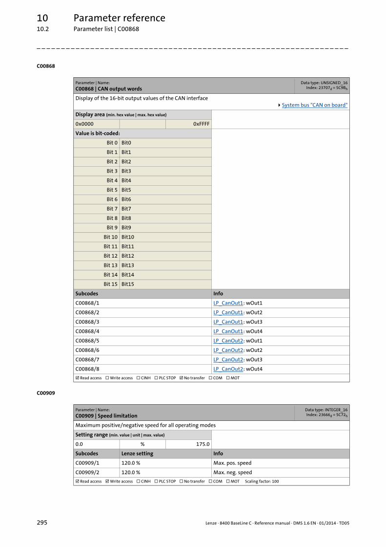
10 Parameter reference10.2 Parameter list | C00868
295 Lenze · 8400 BaseLine C · Reference manual · DMS 1.6 EN · 01/2014 · TD05
_ _ _ _ _ _ _ _ _ _ _ _ _ _ _ _ _ _ _ _ _ _ _ _ _ _ _ _ _ _ _ _ _ _ _ _ _ _ _ _ _ _ _ _ _ _ _ _ _ _ _ _ _ _ _ _ _ _ _ _ _ _ _ _
C00868
C00909
Parameter | Name:
C00868 | CAN output wordsData type: UNSIGNED_16
Index: 23707d = 5C9Bh
Display of the 16-bit output values of the CAN interfaceSystem bus "CAN on board"
Display area (min. hex value | max. hex value)
0x0000 0xFFFF
Value is bit-coded:
Bit 0 Bit0
Bit 1 Bit1
Bit 2 Bit2
Bit 3 Bit3
Bit 4 Bit4
Bit 5 Bit5
Bit 6 Bit6
Bit 7 Bit7
Bit 8 Bit8
Bit 9 Bit9
Bit 10 Bit10
Bit 11 Bit11
Bit 12 Bit12
Bit 13 Bit13
Bit 14 Bit14
Bit 15 Bit15
Subcodes Info
C00868/1 LP_CanOut1: wOut1
C00868/2 LP_CanOut1: wOut2
C00868/3 LP_CanOut1: wOut3
C00868/4 LP_CanOut1: wOut4
C00868/5 LP_CanOut2: wOut1
C00868/6 LP_CanOut2: wOut2
C00868/7 LP_CanOut2: wOut3
C00868/8 LP_CanOut2: wOut4
Read access Write access CINH PLC STOP No transfer COM MOT
Parameter | Name:
C00909 | Speed limitationData type: INTEGER_16Index: 23666d = 5C72h
Maximum positive/negative speed for all operating modes
Setting range (min. value | unit | max. value)
0.0 % 175.0
Subcodes Lenze setting Info
C00909/1 120.0 % Max. pos. speed
C00909/2 120.0 % Max. neg. speed
Read access Write access CINH PLC STOP No transfer COM MOT Scaling factor: 100

Lenze · 8400 BaseLine C · Reference manual · DMS 1.6 EN · 01/2014 · TD05 296
10 Parameter reference10.2 Parameter list | C00910
_ _ _ _ _ _ _ _ _ _ _ _ _ _ _ _ _ _ _ _ _ _ _ _ _ _ _ _ _ _ _ _ _ _ _ _ _ _ _ _ _ _ _ _ _ _ _ _ _ _ _ _ _ _ _ _ _ _ _ _ _ _ _ _
C00910
C00990
C00991
C00992
Parameter | Name:
C00910 | Frequency limitationData type: UNSIGNED_16
Index: 23665d = 5C71h
Maximum positive/negative output frequency for all operating modes
Setting range (min. value | unit | max. value)
0 Hz 300
Subcodes Lenze setting Info
C00910/1 300 Hz Max. pos. output frequency
C00910/2 300 Hz Max. neg. output frequency
Read access Write access CINH PLC STOP No transfer COM MOT Scaling factor: 1
Parameter | Name:
C00990 | Flying restart fct.: ActivationData type: UNSIGNED_8
Index: 23585d = 5C21h
Switch on /activate flying restart circuit for non-feedback drive systemsFlying restart function
Selection list (Lenze setting printed in bold)
0 Off
1 On
Read access Write access CINH PLC STOP No transfer COM MOT Scaling factor: 1
Parameter | Name:
C00991 | Flying restart fct.: ProcessData type: UNSIGNED_16
Index: 23584d = 5C20h
Selection of the speed search range for flying restart functionFlying restart function
Selection list (Lenze setting printed in bold)
5 -n...+n | Last output frequency
6 -n...+n | Actual setpoint frequency
Read access Write access CINH PLC STOP No transfer COM MOT Scaling factor: 1
Parameter | Name:
C00992 | Flying restart: Start frequencyData type: INTEGER_16Index: 23583d = 5C1Fh
Selection of the starting value for the flying restart functionFlying restart function
Setting range (min. value | unit | max. value) Lenze setting
-200 Hz 200 10 Hz
Read access Write access CINH PLC STOP No transfer COM MOT Scaling factor: 1
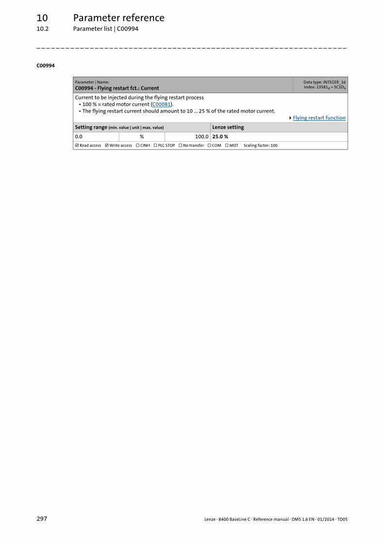
10 Parameter reference10.2 Parameter list | C00994
297 Lenze · 8400 BaseLine C · Reference manual · DMS 1.6 EN · 01/2014 · TD05
_ _ _ _ _ _ _ _ _ _ _ _ _ _ _ _ _ _ _ _ _ _ _ _ _ _ _ _ _ _ _ _ _ _ _ _ _ _ _ _ _ _ _ _ _ _ _ _ _ _ _ _ _ _ _ _ _ _ _ _ _ _ _ _
C00994
Parameter | Name:
C00994 - Flying restart fct.: CurrentData type: INTEGER_16Index: 23581d = 5C1Dh
Current to be injected during the flying restart process• 100 % ≡ rated motor current (C00081).• The flying restart current should amount to 10 ... 25 % of the rated motor current.
Flying restart function
Setting range (min. value | unit | max. value) Lenze setting
0.0 % 100.0 25.0 %
Read access Write access CINH PLC STOP No transfer COM MOT Scaling factor: 100

Lenze · 8400 BaseLine C · Reference manual · DMS 1.6 EN · 01/2014 · TD05 298
10 Parameter reference10.2 Parameter list
_ _ _ _ _ _ _ _ _ _ _ _ _ _ _ _ _ _ _ _ _ _ _ _ _ _ _ _ _ _ _ _ _ _ _ _ _ _ _ _ _ _ _ _ _ _ _ _ _ _ _ _ _ _ _ _ _ _ _ _ _ _ _ _
10.2.1 Selection lists for configuration parameters
10.2.1.1 Selection list - analog signals
This selection list is relevant for the followingparameters:
Parameter
C00620 16-bit system connection
C00700 LA_NCtrl: Analog connection list
Selection list - analog signals
0 Not connected
1 C_nPos100_a(100.0%)
2 C_nNeg100_a(-100.0%)
3 C_nPos199_9_a(199.9%)
4 C_nNeg199_9_a(-199.9%)
5 C_w65535
6 C_wDriveCtrl
10 AIn1_Out
20 nPar1_a
21 nPar2_a
22 nPar3_a
23 nPar4_a
24 LS_Keypad_nTorqueMotLim_a
25 LS_Keypad_nTorqueGenLim_a
26 LS_Keypad_nMainSetValue_a
30 CAN1_wIn1
31 CAN1_wIn2
32 CAN1_wIn3
33 CAN1_wIn4
34 CAN2_wIn1
35 CAN2_wIn2
36 CAN2_wIn3
37 CAN2_wIn4
50 LA_NCtrl_nMotorFreqAct_a
51 LA_NCtrl_nMotorSpeedSet_a
52 LA_NCtrl_nMotorSpeedAct_a
53 LA_NCtrl_nMotor Voltage_a
54 LA_NCtrl_nDCVoltage_a
55 LA_NCtrl_nMotorCurrent_a
56 LA_NCtrl_nMotorTorqueAct_a
57 LA_NCtrl_nHeatsinktemperature_a
58 LA_NCtrl_nOutputSpeedCtrl_a
70 LA_NCtrl_wDeviceStateWord
71 LA_NCtrl_wDeviceAuxStateWord
72 LA_NCtrl_wDetermFailNoLow
73 LA_NCtrl_wDetermFailNoHigh
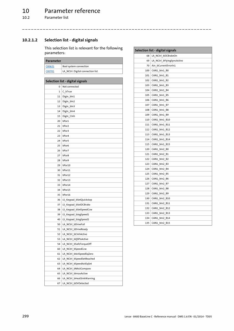
10 Parameter reference10.2 Parameter list
299 Lenze · 8400 BaseLine C · Reference manual · DMS 1.6 EN · 01/2014 · TD05
_ _ _ _ _ _ _ _ _ _ _ _ _ _ _ _ _ _ _ _ _ _ _ _ _ _ _ _ _ _ _ _ _ _ _ _ _ _ _ _ _ _ _ _ _ _ _ _ _ _ _ _ _ _ _ _ _ _ _ _ _ _ _ _
10.2.1.2 Selection list - digital signals
This selection list is relevant for the followingparameters:
Parameter
C00621 Bool system connection
C00701 LA_NCtrl: Digital connection list
Selection list - digital signals
0 Not connected
1 C_bTrue
11 DigIn_bIn1
12 DigIn_bIn2
13 DigIn_bIn3
14 DigIn_bIn4
15 DigIn_CInh
20 bPar1
21 bPar2
22 bPar3
23 bPar4
24 bPar5
25 bPar6
26 bPar7
27 bPar8
28 bPar9
29 bPar10
30 bPar11
31 bPar12
32 bPar13
33 bPar14
34 bPar15
35 bPar16
36 LS_Keypad_bSetQuickstop
37 LS_Keypad_bSetDCBrake
38 LS_Keypad_bSetSpeedCcw
39 LS_Keypad_bJogSpeed1
40 LS_Keypad_bJogSpeed2
50 LA_NCtrl_bDriveFail
51 LA_NCtrl_bDriveReady
52 LA_NCtrl_bCInhActive
53 LA_NCtrl_bQSPIsActive
54 LA_NCtrl_bSafeTorqueOff
60 LA_NCtrl_bSpeedCcw
61 LA_NCtrl_bActSpeedEqZero
62 LA_NCtrl_bSpeedSetReached
63 LA_NCtrl_bSpeedActEqSet
64 LA_NCtrl_bNActCompare
65 LA_NCtrl_bImaxActive
66 LA_NCtrl_bHeatSinkWarning
67 LA_NCtrl_bOVDetected
68 LA_NCtrl_bDCBrakeOn
69 LA_NCtrl_bFlyingSyncActive
70 Ain_bCurrentErrorIn1
100 CAN1_bIn1_B0
101 CAN1_bIn1_B1
102 CAN1_bIn1_B2
103 CAN1_bIn1_B3
104 CAN1_bIn1_B4
105 CAN1_bIn1_B5
106 CAN1_bIn1_B6
107 CAN1_bIn1_B7
108 CAN1_bIn1_B8
109 CAN1_bIn1_B9
110 CAN1_bIn1_B10
111 CAN1_bIn1_B11
112 CAN1_bIn1_B12
113 CAN1_bIn1_B13
114 CAN1_bIn1_B14
115 CAN1_bIn1_B15
120 CAN1_bIn2_B0
121 CAN1_bIn2_B1
122 CAN1_bIn2_B2
123 CAN1_bIn2_B3
124 CAN1_bIn2_B4
125 CAN1_bIn2_B5
126 CAN1_bIn2_B6
127 CAN1_bIn2_B7
128 CAN1_bIn2_B8
129 CAN1_bIn2_B9
130 CAN1_bIn2_B10
131 CAN1_bIn2_B11
132 CAN1_bIn2_B12
133 CAN1_bIn2_B13
134 CAN1_bIn2_B14
135 CAN1_bIn2_B15
Selection list - digital signals
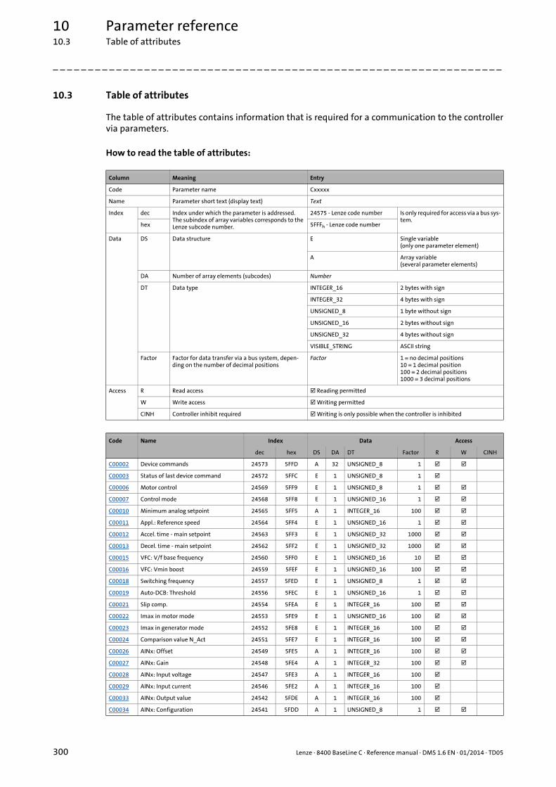
10 Parameter reference10.3 Table of attributes
300 Lenze · 8400 BaseLine C · Reference manual · DMS 1.6 EN · 01/2014 · TD05
_ _ _ _ _ _ _ _ _ _ _ _ _ _ _ _ _ _ _ _ _ _ _ _ _ _ _ _ _ _ _ _ _ _ _ _ _ _ _ _ _ _ _ _ _ _ _ _ _ _ _ _ _ _ _ _ _ _ _ _ _ _ _ _
10.3 Table of attributes
The table of attributes contains information that is required for a communication to the controllervia parameters.
How to read the table of attributes:
Column Meaning Entry
Code Parameter name Cxxxxx
Name Parameter short text (display text) Text
Index dec Index under which the parameter is addressed.The subindex of array variables corresponds to the Lenze subcode number.
24575 - Lenze code number Is only required for access via a bus sys-tem.
hex 5FFFh - Lenze code number
Data DS Data structure E Single variable (only one parameter element)
A Array variable(several parameter elements)
DA Number of array elements (subcodes) Number
DT Data type INTEGER_16 2 bytes with sign
INTEGER_32 4 bytes with sign
UNSIGNED_8 1 byte without sign
UNSIGNED_16 2 bytes without sign
UNSIGNED_32 4 bytes without sign
VISIBLE_STRING ASCII string
Factor Factor for data transfer via a bus system, depen-ding on the number of decimal positions
Factor 1 ≡ no decimal positions10 ≡ 1 decimal position100 ≡ 2 decimal positions1000 ≡ 3 decimal positions
Access R Read access Reading permitted
W Write access Writing permitted
CINH Controller inhibit required Writing is only possible when the controller is inhibited
Code Name Index Data Access
dec hex DS DA DT Factor R W CINH
C00002 Device commands 24573 5FFD A 32 UNSIGNED_8 1
C00003 Status of last device command 24572 5FFC E 1 UNSIGNED_8 1
C00006 Motor control 24569 5FF9 E 1 UNSIGNED_8 1
C00007 Control mode 24568 5FF8 E 1 UNSIGNED_16 1
C00010 Minimum analog setpoint 24565 5FF5 A 1 INTEGER_16 100
C00011 Appl.: Reference speed 24564 5FF4 E 1 UNSIGNED_16 1
C00012 Accel. time - main setpoint 24563 5FF3 E 1 UNSIGNED_32 1000
C00013 Decel. time - main setpoint 24562 5FF2 E 1 UNSIGNED_32 1000
C00015 VFC: V/f base frequency 24560 5FF0 E 1 UNSIGNED_16 10
C00016 VFC: Vmin boost 24559 5FEF E 1 UNSIGNED_16 100
C00018 Switching frequency 24557 5FED E 1 UNSIGNED_8 1
C00019 Auto-DCB: Threshold 24556 5FEC E 1 UNSIGNED_16 1
C00021 Slip comp. 24554 5FEA E 1 INTEGER_16 100
C00022 Imax in motor mode 24553 5FE9 E 1 UNSIGNED_16 100
C00023 Imax in generator mode 24552 5FE8 E 1 INTEGER_16 100
C00024 Comparison value N_Act 24551 5FE7 E 1 INTEGER_16 100
C00026 AINx: Offset 24549 5FE5 A 1 INTEGER_16 100
C00027 AINx: Gain 24548 5FE4 A 1 INTEGER_32 100
C00028 AINx: Input voltage 24547 5FE3 A 1 INTEGER_16 100
C00029 AINx: Input current 24546 5FE2 A 1 INTEGER_16 100
C00033 AINx: Output value 24542 5FDE A 1 INTEGER_16 100
C00034 AINx: Configuration 24541 5FDD A 1 UNSIGNED_8 1
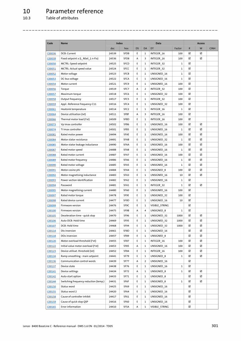
Lenze · 8400 BaseLine C · Reference manual · DMS 1.6 EN · 01/2014 · TD05 301
10 Parameter reference10.3 Table of attributes
_ _ _ _ _ _ _ _ _ _ _ _ _ _ _ _ _ _ _ _ _ _ _ _ _ _ _ _ _ _ _ _ _ _ _ _ _ _ _ _ _ _ _ _ _ _ _ _ _ _ _ _ _ _ _ _ _ _ _ _ _ _ _ _
C00036 DCB: Current 24539 5FDB E 1 INTEGER_16 100
C00039 Fixed setpoint x (L_NSet_1 n-Fix) 24536 5FD8 A 3 INTEGER_16 100
C00050 MCTRL: Speed setpoint 24525 5FCD E 1 INTEGER_32 1
C00051 MCTRL: Actual speed value 24524 5FCC E 1 INTEGER_32 1
C00052 Motor voltage 24523 5FCB E 1 UNSIGNED_16 1
C00053 DC-bus voltage 24522 5FCA E 1 UNSIGNED_16 1
C00054 Motor current 24521 5FC9 E 1 UNSIGNED_16 100
C00056 Torque 24519 5FC7 A 2 INTEGER_32 100
C00057 Maximum torque 24518 5FC6 E 1 UNSIGNED_32 100
C00058 Output frequency 24517 5FC5 E 1 INTEGER_32 100
C00059 Appl.: Reference frequency C11 24516 5FC4 E 1 UNSIGNED_32 100
C00061 Heatsink temperature 24514 5FC2 E 1 INTEGER_16 1
C00064 Device utilisation (Ixt) 24511 5FBF A 3 INTEGER_16 100
C00066 Thermal motor load (I²xt) 24509 5FBD E 1 INTEGER_16 100
C00073 Vp Imax controller 24502 5FB6 E 1 UNSIGNED_16 100
C00074 Ti Imax controller 24501 5FB5 E 1 UNSIGNED_16 1
C00081 Rated motor power 24494 5FAE E 1 UNSIGNED_16 100
C00084 Motor stator resistance 24491 5FAB E 1 UNSIGNED_32 1
C00085 Motor stator leakage inductance 24490 5FAA E 1 UNSIGNED_16 100
C00087 Rated motor speed 24488 5FA8 E 1 UNSIGNED_16 1
C00088 Rated motor current 24487 5FA7 E 1 UNSIGNED_16 100
C00089 Rated motor frequency 24486 5FA6 E 1 UNSIGNED_16 1
C00090 Rated motor voltage 24485 5FA5 E 1 UNSIGNED_16 1
C00091 Motor cosine phi 24484 5FA4 E 1 UNSIGNED_8 100
C00092 Motor magnetising inductance 24483 5FA3 E 1 UNSIGNED_16 10
C00093 Power section identification 24482 5FA2 E 1 UNSIGNED_16 1
C00094 Password 24481 5FA1 E 1 INTEGER_32 1
C00095 Motor magnetising current 24480 5FA0 E 1 UNSIGNED_16 100
C00097 Rated motor torque 24478 5F9E E 1 UNSIGNED_32 100
C00098 Rated device current 24477 5F9D E 1 UNSIGNED_16 10
C00099 Firmware version 24476 5F9C E 1 VISIBLE_STRING
C00100 Firmware version 24475 5F9B A 4 UNSIGNED_8 1
C00105 Deceleration time - quick stop 24470 5F96 E 1 UNSIGNED_32 1000
C00106 Auto-DCB: Hold time 24469 5F95 E 1 UNSIGNED_32 1000
C00107 DCB: Hold time 24468 5F94 E 1 UNSIGNED_32 1000
C00114 DIx inversion 24461 5F8D E 1 UNSIGNED_16
C00118 DOx inversion 24457 5F89 E 1 UNSIGNED_8
C00120 Motor overload threshold (I²xt) 24455 5F87 E 1 INTEGER_16 100
C00122 Initial value motor overload (I²xt) 24453 5F85 A 1 UNSIGNED_16 100
C00123 Device utilisat. threshold (Ixt) 24452 5F84 E 1 INTEGER_16 100
C00134 Ramp smoothing - main setpoint 24441 5F79 E 1 UNSIGNED_8 1
C00136 Communication control words 24439 5F77 A 2 UNSIGNED_16
C00137 Device state 24438 5F76 E 1 UNSIGNED_16 1
C00141 Device settings 24434 5F72 A 1 UNSIGNED_8 1
C00142 Auto-start option 24433 5F71 E 1 UNSIGNED_8
C00144 Switching frequency reduction (temp.) 24431 5F6F E 1 UNSIGNED_8 1
C00150 Status word 24425 5F69 E 1 UNSIGNED_16
C00155 Status word 2 24420 5F64 E 1 UNSIGNED_16
C00158 Cause of controller inhibit 24417 5F61 E 1 UNSIGNED_16
C00159 Cause of quick stop QSP 24416 5F60 E 1 UNSIGNED_16
C00165 Error information 24410 5F5A A 1 VISIBLE_STRING
Code Name Index Data Access
dec hex DS DA DT Factor R W CINH
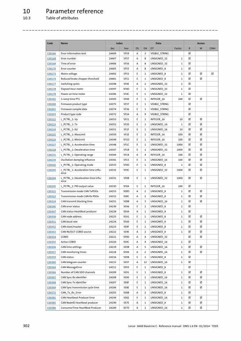
10 Parameter reference10.3 Table of attributes
302 Lenze · 8400 BaseLine C · Reference manual · DMS 1.6 EN · 01/2014 · TD05
_ _ _ _ _ _ _ _ _ _ _ _ _ _ _ _ _ _ _ _ _ _ _ _ _ _ _ _ _ _ _ _ _ _ _ _ _ _ _ _ _ _ _ _ _ _ _ _ _ _ _ _ _ _ _ _ _ _ _ _ _ _ _ _
C00166 Error information text 24409 5F59 A 3 VISIBLE_STRING
C00168 Error number 24407 5F57 A 8 UNSIGNED_32 1
C00169 Time of error 24406 5F56 A 8 UNSIGNED_32 1
C00170 Error counter 24405 5F55 A 8 UNSIGNED_8 1
C00173 Mains voltage 24402 5F52 E 1 UNSIGNED_8 1
C00174 Reduced brake chopper threshold 24401 5F51 E 1 UNSIGNED_8 1
C00177 Switching cycles 24398 5F4E A 2 UNSIGNED_32 1
C00178 Elapsed-hour meter 24397 5F4D E 1 UNSIGNED_32 1
C00179 Power-on time meter 24396 5F4C E 1 UNSIGNED_32 1
C00182 S-ramp time PT1 24393 5F49 E 1 INTEGER_16 100
C00200 Firmware product type 24375 5F37 E 1 VISIBLE_STRING
C00201 Firmware compile date 24374 5F36 E 1 VISIBLE_STRING
C00203 Product type code 24372 5F34 A 9 VISIBLE_STRING
C00222 L_PCTRL_1: Vp 24353 5F21 E 1 INTEGER_16 10
C00223 L_PCTRL_1: Tn 24352 5F20 E 1 UNSIGNED_16 1
C00224 L_PCTRL_1: Kd 24351 5F1F E 1 UNSIGNED_16 10
C00225 L_PCTRL_1: MaxLimit 24350 5F1E E 1 INTEGER_16 100
C00226 L_PCTRL_1: MinLimit 24349 5F1D E 1 INTEGER_16 100
C00227 L_PCTRL_1: Acceleration time 24348 5F1C E 1 UNSIGNED_32 1000
C00228 L_PCTRL_1: Deceleration time 24347 5F1B E 1 UNSIGNED_32 1000
C00231 L_PCTRL_1: Operating range 24344 5F18 A 4 INTEGER_16 100
C00234 Oscillation damping influence 24341 5F15 E 1 UNSIGNED_16 100
C00242 L_PCTRL_1: Operating mode 24333 5F0D E 1 UNSIGNED_8 1
C00243 L_PCTRL_1: Acceleration time influ-ence
24332 5F0C E 1 UNSIGNED_32 1000
C00244 L_PCTRL_1: Deceleration time influ-ence
24331 5F0B E 1 UNSIGNED_32 1000
C00245 L_PCTRL_1: PID output value 24330 5F0A E 1 INTEGER_16 100
C00322 Transmission mode CAN TxPDOs 24253 5EBD A 2 UNSIGNED_8 1
C00323 Transmission mode CAN Rx PDOs 24252 5EBC A 2 UNSIGNED_8 1
C00324 CAN transmit blocking time 24251 5EBB A 3 UNSIGNED_16 1
C00345 CAN error status 24230 5EA6 E 1 UNSIGNED_8 1
C00347 CAN status HeartBeat producer 24228 5EA4 A 1 UNSIGNED_8 1
C00350 CAN node address 24225 5EA1 E 1 UNSIGNED_8 1
C00351 CAN baud rate 24224 5EA0 E 1 UNSIGNED_8 1
C00352 CAN slave/master 24223 5E9F E 1 UNSIGNED_8 1
C00353 CAN IN/OUT COBID source 24222 5E9E A 2 UNSIGNED_8 1
C00354 COBID 24221 5E9D A 4 UNSIGNED_32
C00355 Active COBID 24220 5E9C A 4 UNSIGNED_16 1
C00356 CAN time settings 24219 5E9B A 5 UNSIGNED_16 1
C00357 CAN monitoring times 24218 5E9A A 2 UNSIGNED_16 1
C00359 CAN status 24216 5E98 E 1 UNSIGNED_8 1
C00360 CAN telegram counter 24215 5E97 A 12 UNSIGNED_16 1
C00364 CAN MessageError 24211 5E93 E 1 UNSIGNED_8
C00366 Number of CAN SDO channels 24209 5E91 E 1 UNSIGNED_8 1
C00367 CAN Sync-Rx identifier 24208 5E90 E 1 UNSIGNED_16 1
C00368 CAN Sync-Tx Identifier 24207 5E8F E 1 UNSIGNED_16 1
C00369 CAN Sync transmission cycle time 24206 5E8E E 1 UNSIGNED_16 1
C00372 CAN_Tx_Rx_Error 24203 5E8B A 2 UNSIGNED_8 1
C00381 CAN Heartbeat Producer time 24194 5E82 E 1 UNSIGNED_16 1
C00385 CAN NodeID Heartbeat producer 24190 5E7E A 1 UNSIGNED_8 1
C00386 ConsumerTime HeartBeat Producer 24189 5E7D A 1 UNSIGNED_16 1
Code Name Index Data Access
dec hex DS DA DT Factor R W CINH

Lenze · 8400 BaseLine C · Reference manual · DMS 1.6 EN · 01/2014 · TD05 303
10 Parameter reference10.3 Table of attributes
_ _ _ _ _ _ _ _ _ _ _ _ _ _ _ _ _ _ _ _ _ _ _ _ _ _ _ _ _ _ _ _ _ _ _ _ _ _ _ _ _ _ _ _ _ _ _ _ _ _ _ _ _ _ _ _ _ _ _ _ _ _ _ _
C00389 PDO valid / invalid 24186 5E7A A 4 UNSIGNED_8 1
C00409 LP_CanIn Mapping 24166 5E66 A 8 UNSIGNED_16 1
C00443 DIx: Level 24132 5E44 A 2 UNSIGNED_16
C00444 DOx: Level 24131 5E43 A 2 UNSIGNED_16
C00470 LS_ParFree_b 24105 5E29 A 16 UNSIGNED_8 1
C00472 LS_ParFree_a 24103 5E27 A 4 INTEGER_16 100
C00480 LS_DisFree_b 24095 5E1F E 1 UNSIGNED_8
C00481 LS_DisFree 24094 5E1E A 4 UNSIGNED_16
C00482 LS_DisFree_a 24093 5E1D A 4 INTEGER_16 100
C00516 Checksums 24059 5DFB A 1 UNSIGNED_32 1
C00517 User menu 24058 5DFA A 20 INTEGER_32 1
C00565 Resp. to mains phase failure 24010 5DCA E 1 UNSIGNED_8 1
C00574 Resp. to brake resist. overtemp. 24001 5DC1 E 1 UNSIGNED_8 1
C00581 Resp. to LS_SetError_x 23994 5DBA A 2 UNSIGNED_8 1
C00592 Resp. to CAN bus connection 23983 5DAF A 5 UNSIGNED_8 1
C00593 Resp. to CANx_IN monitoring 23982 5DAE A 2 UNSIGNED_8 1
C00594 Resp. to control word error 23981 5DAD A 1 UNSIGNED_8 1
C00598 Resp. to open circuit AINx 23977 5DA9 A 1 UNSIGNED_8 1
C00600 Resp. to DC bus undervoltage 23975 5DA7 A 1 UNSIGNED_8 1
C00601 Del. resp.to fault: DC bus overvoltage 23974 5DA6 A 1 UNSIGNED_16 1000
C00604 Resp. to device overload (Ixt) 23971 5DA3 E 1 UNSIGNED_8 1
C00606 Resp. to motor overload (I²xt) 23969 5DA1 E 1 UNSIGNED_8 1
C00620 16-bit system connection 23955 5D93 A 27 UNSIGNED_16 1
C00621 Bool system connection 23954 5D92 A 61 UNSIGNED_16 1
C00700 LA_NCtrl: Analog connection list 23875 5D43 A 9 UNSIGNED_16 1
C00701 LA_NCtrl: Digital connection list 23874 5D42 A 18 UNSIGNED_16 1
C00725 Current switching frequency 23850 5D2A E 1 UNSIGNED_8 1
C00727 LS_Keypad: Digital values 23848 5D28 A 5 UNSIGNED_8 1
C00728 LS_Keypad: Keypad analog values 23847 5D27 A 3 INTEGER_16 100
C00800 L_MPot_1: Upper limit 23775 5CDF E 1 INTEGER_16 100
C00801 L_MPot_1: Lower limit 23774 5CDE E 1 INTEGER_16 100
C00802 L_MPot_1: Acceleration time 23773 5CDD E 1 UNSIGNED_16 10
C00803 L_MPot_1: Deceleration time 23772 5CDC E 1 UNSIGNED_16 10
C00804 L_MPot_1: Inactive function 23771 5CDB E 1 UNSIGNED_8 1
C00805 L_MPot_1: Init function 23770 5CDA E 1 UNSIGNED_8 1
C00806 L_MPot_1: Use 23769 5CD9 E 1 UNSIGNED_8 1
C00830 16-bit analog input 23745 5CC1 A 11 INTEGER_16 100
C00831 16-bit common input 23744 5CC0 A 1 UNSIGNED_16
C00833 8-bit input 23742 5CBE A 24 UNSIGNED_8 1
C00866 CAN input words 23709 5C9D A 8 UNSIGNED_16
C00868 CAN output words 23707 5C9B A 8 UNSIGNED_16
C00909 Speed limitation 23666 5C72 A 2 INTEGER_16 100
C00910 Frequency limitation 23665 5C71 A 2 UNSIGNED_16 1
C00990 Flying restart fct.: Activation 23585 5C21 E 1 UNSIGNED_8 1
C00991 Flying restart fct.: Process 23584 5C20 E 1 UNSIGNED_16 1
C00992 Flying restart: Start frequency 23583 5C1F E 1 INTEGER_16 1
C00994 Flying restart fct.: Current 23581 5C1D E 1 INTEGER_16 100
Code Name Index Data Access
dec hex DS DA DT Factor R W CINH
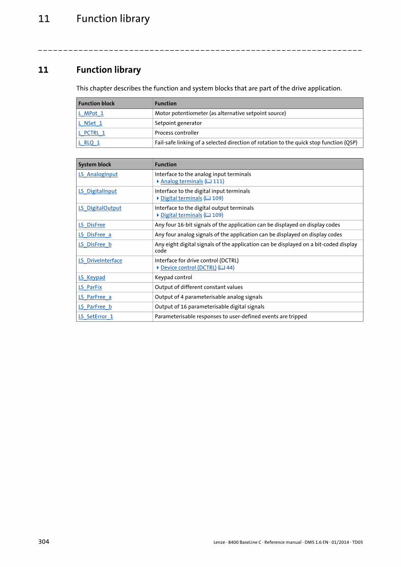
11 Function library
304 Lenze · 8400 BaseLine C · Reference manual · DMS 1.6 EN · 01/2014 · TD05
_ _ _ _ _ _ _ _ _ _ _ _ _ _ _ _ _ _ _ _ _ _ _ _ _ _ _ _ _ _ _ _ _ _ _ _ _ _ _ _ _ _ _ _ _ _ _ _ _ _ _ _ _ _ _ _ _ _ _ _ _ _ _ _
11 Function library
This chapter describes the function and system blocks that are part of the drive application.
Function block Function
L_MPot_1 Motor potentiometer (as alternative setpoint source)
L_NSet_1 Setpoint generator
L_PCTRL_1 Process controller
L_RLQ_1 Fail-safe linking of a selected direction of rotation to the quick stop function (QSP)
System block Function
LS_AnalogInput Interface to the analog input terminalsAnalog terminals ( 111)
LS_DigitalInput Interface to the digital input terminalsDigital terminals ( 109)
LS_DigitalOutput Interface to the digital output terminalsDigital terminals ( 109)
LS_DisFree Any four 16-bit signals of the application can be displayed on display codes
LS_DisFree_a Any four analog signals of the application can be displayed on display codes
LS_DisFree_b Any eight digital signals of the application can be displayed on a bit-coded display code
LS_DriveInterface Interface for drive control (DCTRL)Device control (DCTRL) ( 44)
LS_Keypad Keypad control
LS_ParFix Output of different constant values
LS_ParFree_a Output of 4 parameterisable analog signals
LS_ParFree_b Output of 16 parameterisable digital signals
LS_SetError_1 Parameterisable responses to user-defined events are tripped
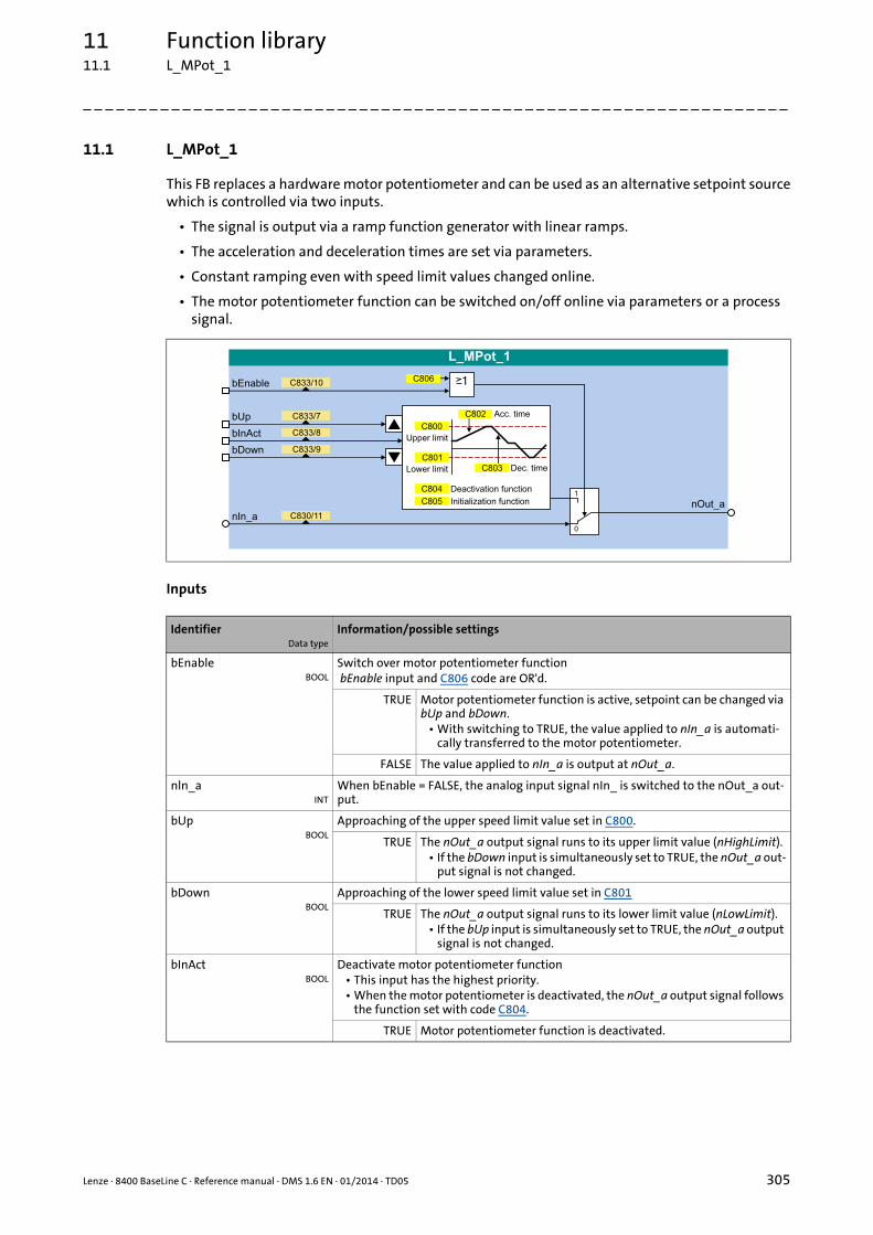
Lenze · 8400 BaseLine C · Reference manual · DMS 1.6 EN · 01/2014 · TD05 305
11 Function library11.1 L_MPot_1
_ _ _ _ _ _ _ _ _ _ _ _ _ _ _ _ _ _ _ _ _ _ _ _ _ _ _ _ _ _ _ _ _ _ _ _ _ _ _ _ _ _ _ _ _ _ _ _ _ _ _ _ _ _ _ _ _ _ _ _ _ _ _ _
11.1 L_MPot_1
This FB replaces a hardware motor potentiometer and can be used as an alternative setpoint sourcewhich is controlled via two inputs.
• The signal is output via a ramp function generator with linear ramps.
• The acceleration and deceleration times are set via parameters.
• Constant ramping even with speed limit values changed online.
• The motor potentiometer function can be switched on/off online via parameters or a process signal.
Inputs
IdentifierData type
Information/possible settings
bEnableBOOL
Switch over motor potentiometer function bEnable input and C806 code are OR'd.
TRUE Motor potentiometer function is active, setpoint can be changed via bUp and bDown.
• With switching to TRUE, the value applied to nIn_a is automati-cally transferred to the motor potentiometer.
FALSE The value applied to nIn_a is output at nOut_a.
nln_aINT
When bEnable = FALSE, the analog input signal nIn_ is switched to the nOut_a out-put.
bUpBOOL
Approaching of the upper speed limit value set in C800.
TRUE The nOut_a output signal runs to its upper limit value (nHighLimit).• If the bDown input is simultaneously set to TRUE, the nOut_a out-
put signal is not changed.
bDownBOOL
Approaching of the lower speed limit value set in C801
TRUE The nOut_a output signal runs to its lower limit value (nLowLimit).• If the bUp input is simultaneously set to TRUE, the nOut_a output
signal is not changed.
bInActBOOL
Deactivate motor potentiometer function• This input has the highest priority.• When the motor potentiometer is deactivated, the nOut_a output signal follows
the function set with code C804.
TRUE Motor potentiometer function is deactivated.

11 Function library11.1 L_MPot_1
306 Lenze · 8400 BaseLine C · Reference manual · DMS 1.6 EN · 01/2014 · TD05
_ _ _ _ _ _ _ _ _ _ _ _ _ _ _ _ _ _ _ _ _ _ _ _ _ _ _ _ _ _ _ _ _ _ _ _ _ _ _ _ _ _ _ _ _ _ _ _ _ _ _ _ _ _ _ _ _ _ _ _ _ _ _ _
Outputs
Parameter
IdentifierData type
Value/meaning
nOut_aINT
Output signal
Parameter Possible settings Info
C800 -199.9 % 199.9 Upper limit• Lenze setting: 100.0 %
C801 -199.9 % 199.9 Lower limit• Lenze setting: -100.0 %
C802 0.1 s 999.9 Acceleration time• Lenze setting: 10.0 s
C803 0.1 s 999.9 Deceleration time• Lenze setting: 10.0 s
C804 Inactive function• Selection of response when deac-
tivating the motor potentiometer via the input bInAct.
0 Keep value(Lenze setting)
No further action; nOut_a retains its value.
1 Deceleration to 0 The motor potentiometer returns to 0 % within the deceleration time Tif.
2 Deceleration to lower limit The motor potentiometer runs within the deceleration time Tif to the lower limit value (C801).
3 Without ramp to 0 Important for the emergency stop functionThe motor potentiometer output im-mediately changes to 0 %
4 Without ramp to lower limit The motor potentiometer output im-mediately changes to the lower limit value (C801).
5 Acceleration to upper limit The motor potentiometer runs with the acceleration time Tir to the upper limit value (C800).
C805 Init function• Selection of response when swit-
ching on the device.
0 Load last value(Lenze setting)
The output value being output du-ring mains power-off is saved non-volatilely in the internal memory of the controller. It will be reloaded du-ring mains power-on.
1 Load lower limit The lower limit value (C801) is loaded during mains power-on.
2 Load 0 An output value = 0 % is loaded du-ring mains power-on.
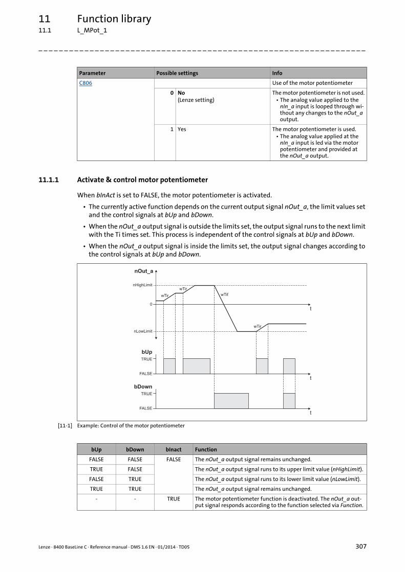
Lenze · 8400 BaseLine C · Reference manual · DMS 1.6 EN · 01/2014 · TD05 307
11 Function library11.1 L_MPot_1
_ _ _ _ _ _ _ _ _ _ _ _ _ _ _ _ _ _ _ _ _ _ _ _ _ _ _ _ _ _ _ _ _ _ _ _ _ _ _ _ _ _ _ _ _ _ _ _ _ _ _ _ _ _ _ _ _ _ _ _ _ _ _ _
11.1.1 Activate & control motor potentiometer
When bInAct is set to FALSE, the motor potentiometer is activated.
• The currently active function depends on the current output signal nOut_a, the limit values set and the control signals at bUp and bDown.
• When the nOut_a output signal is outside the limits set, the output signal runs to the next limit with the Ti times set. This process is independent of the control signals at bUp and bDown.
• When the nOut_a output signal is inside the limits set, the output signal changes according to the control signals at bUp and bDown.
[11-1] Example: Control of the motor potentiometer
C806 Use of the motor potentiometer
0 No(Lenze setting)
The motor potentiometer is not used.• The analog value applied to the
nIn_a input is looped through wi-thout any changes to the nOut_a output.
1 Yes The motor potentiometer is used.• The analog value applied at the
nIn_a input is led via the motor potentiometer and provided at the nOut_a output.
Parameter Possible settings Info
nOut_a
t
t
TRUE
FALSE
bUp
t
TRUE
FALSE
bDown
nHighLimit
nLowLimit
0
wTir
wTir
wTif
wTir
bUp bDown bInact Function
FALSE FALSE FALSE The nOut_a output signal remains unchanged.
TRUE FALSE The nOut_a output signal runs to its upper limit value (nHighLimit).
FALSE TRUE The nOut_a output signal runs to its lower limit value (nLowLimit).
TRUE TRUE The nOut_a output signal remains unchanged.
- - TRUE The motor potentiometer function is deactivated. The nOut_a out-put signal responds according to the function selected via Function.
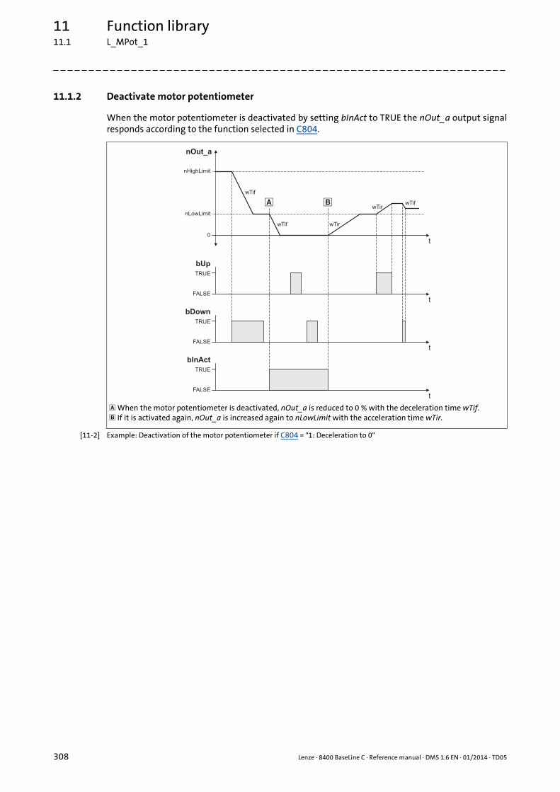
11 Function library11.1 L_MPot_1
308 Lenze · 8400 BaseLine C · Reference manual · DMS 1.6 EN · 01/2014 · TD05
_ _ _ _ _ _ _ _ _ _ _ _ _ _ _ _ _ _ _ _ _ _ _ _ _ _ _ _ _ _ _ _ _ _ _ _ _ _ _ _ _ _ _ _ _ _ _ _ _ _ _ _ _ _ _ _ _ _ _ _ _ _ _ _
11.1.2 Deactivate motor potentiometer
When the motor potentiometer is deactivated by setting bInAct to TRUE the nOut_a output signalresponds according to the function selected in C804.
[11-2] Example: Deactivation of the motor potentiometer if C804 = "1: Deceleration to 0"
When the motor potentiometer is deactivated, nOut_a is reduced to 0 % with the deceleration time wTif. If it is activated again, nOut_a is increased again to nLowLimit with the acceleration time wTir.
nOut_a
t
t
TRUE
FALSE
bUp
t
TRUE
FALSE
bDown
nHighLimit
nLowLimit
0
wTir
wTif
wTir
t
TRUE
FALSE
bInAct
wTif
wTif� �
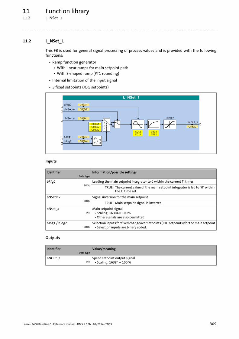
Lenze · 8400 BaseLine C · Reference manual · DMS 1.6 EN · 01/2014 · TD05 309
11 Function library11.2 L_NSet_1
_ _ _ _ _ _ _ _ _ _ _ _ _ _ _ _ _ _ _ _ _ _ _ _ _ _ _ _ _ _ _ _ _ _ _ _ _ _ _ _ _ _ _ _ _ _ _ _ _ _ _ _ _ _ _ _ _ _ _ _ _ _ _ _
11.2 L_NSet_1
This FB is used for general signal processing of process values and is provided with the followingfunctions:
• Ramp function generator• With linear ramps for main setpoint path• With S-shaped ramp (PT1 rounding)
• Internal limitation of the input signal
• 3 fixed setpoints (JOG setpoints)
Inputs
Outputs
IdentifierData type
Information/possible settings
bRfg0BOOL
Leading the main setpoint integrator to 0 within the current Ti times
TRUE The current value of the main setpoint integrator is led to "0" within the Ti time set.
bNSetInvBOOL
Signal inversion for the main setpoint
TRUE Main setpoint signal is inverted.
nNset_aINT
Main setpoint signal• Scaling: 16384 ≡ 100 %• Other signals are also permitted
bJog1 / bJog2BOOL
Selection inputs for fixed changeover setpoints (JOG setpoints) for the main setpoint• Selection inputs are binary coded.
IdentifierData type
Value/meaning
nNOut_aINT
Speed setpoint output signal• Scaling: 16384 ≡ 100 %
11 Function library11.2 L_NSet_1
310 Lenze · 8400 BaseLine C · Reference manual · DMS 1.6 EN · 01/2014 · TD05
_ _ _ _ _ _ _ _ _ _ _ _ _ _ _ _ _ _ _ _ _ _ _ _ _ _ _ _ _ _ _ _ _ _ _ _ _ _ _ _ _ _ _ _ _ _ _ _ _ _ _ _ _ _ _ _ _ _ _ _ _ _ _ _
Parameter
11.2.1 Main setpoint path
• The signals in the main setpoint path are limited to a value range of ±32767.
• The signal at nNSet_a is first led via the JOG selection function.
• A selected JOG value switches the nNSet_a input inactive. Then, the subsequent signal conditio-ning operates with the JOG value.
11.2.2 JOG setpoints
In addition to the direct main setpoint selection, via the input nNSet_a JOG setpoints can be set un-der C039/1...3.
• The JOG setpoints are binary-coded and can be called using the bJog1 and bJog8 selection in-puts:
• The number of selection inputs to be assigned depends on the number of JOG setpoints re-quired.
Parameter Possible settings Info
C012 0.0 s 999.9 Acceleration time Tir for the main set-point
• Lenze setting: 2.0 s
C013 0.000 s 999.9 Deceleration time Tif for the main setpoint
• Lenze setting: 2.0 s
C039/1 -199.9 % 199.9 Fixed setpoint 1 (JOG setpoint 1)• Lenze setting: 40.0 %
C039/2 -199.9 % 199.9 Fixed setpoint 2 (JOG setpoint 2)• Lenze setting: 60.0 %
C039/3 -199.9 % 199.9 Fixed setpoint 3 (JOG setpoint 3)• Lenze setting: 80.0 %
C134 Activates ramp rounding with PT1 behaviour for the main setpoint
• The corresponding S-ramp time must be set in C182.
• Lenze setting: 0 (deactivated)
0 Off
1 PT1 behaviour
C182 0.01 s 50.00 S-ramp time PT1• Lenze setting: 20.00 s
Selection inputs Used main setpoint
bJog2 bJog1
FALSE FALSE nNSet_a
FALSE TRUE C039/1
TRUE FALSE C039/2
TRUE TRUE C039/3
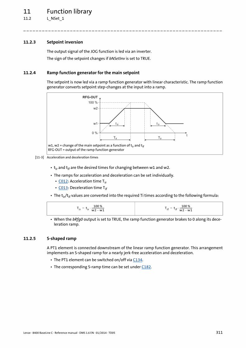
Lenze · 8400 BaseLine C · Reference manual · DMS 1.6 EN · 01/2014 · TD05 311
11 Function library11.2 L_NSet_1
_ _ _ _ _ _ _ _ _ _ _ _ _ _ _ _ _ _ _ _ _ _ _ _ _ _ _ _ _ _ _ _ _ _ _ _ _ _ _ _ _ _ _ _ _ _ _ _ _ _ _ _ _ _ _ _ _ _ _ _ _ _ _ _
11.2.3 Setpoint inversion
The output signal of the JOG function is led via an inverter.
The sign of the setpoint changes if bNSetInv is set to TRUE.
11.2.4 Ramp function generator for the main setpoint
The setpoint is now led via a ramp function generator with linear characteristic. The ramp functiongenerator converts setpoint step-changes at the input into a ramp.
[11-3] Acceleration and deceleration times
• tir and tif are the desired times for changing between w1 and w2.
• The ramps for acceleration and deceleration can be set individually.• C012: Acceleration time Tir
• C013: Deceleration time Tif
• The tir/tif values are converted into the required Ti times according to the following formula:
• When the bRfg0 output is set to TRUE, the ramp function generator brakes to 0 along its dece-leration ramp.
11.2.5 S-shaped ramp
A PT1 element is connected downstream of the linear ramp function generator. This arrangementimplements an S-shaped ramp for a nearly jerk-free acceleration and deceleration.
• The PT1 element can be switched on/off via C134.
• The corresponding S-ramp time can be set under C182.
w1, w2 = change of the main setpoint as a function of tir and tifRFG-OUT = output of the ramp function generator
RFG-OUT
100 %
w2
w1
t0 %
t ir t ir
Tir Tir
Tir tir100 %
w2 w1–-----------------------⋅= Tif tif
100 %w2 w1–-----------------------⋅=
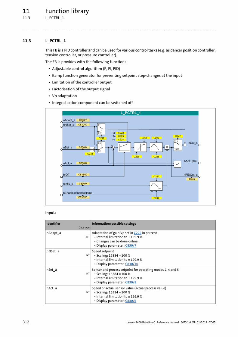
11 Function library11.3 L_PCTRL_1
312 Lenze · 8400 BaseLine C · Reference manual · DMS 1.6 EN · 01/2014 · TD05
_ _ _ _ _ _ _ _ _ _ _ _ _ _ _ _ _ _ _ _ _ _ _ _ _ _ _ _ _ _ _ _ _ _ _ _ _ _ _ _ _ _ _ _ _ _ _ _ _ _ _ _ _ _ _ _ _ _ _ _ _ _ _ _
11.3 L_PCTRL_1
This FB is a PID controller and can be used for various control tasks (e.g. as dancer position controller,tension controller, or pressure controller).
The FB is provides with the following functions:
• Adjustable control algorithm (P, PI, PID)
• Ramp function generator for preventing setpoint step-changes at the input
• Limitation of the controller output
• Factorisation of the output signal
• Vp adaptation
• Integral action component can be switched off
Inputs
IdentifierData type
Information/possible settings
nAdapt_aINT
Adaptation of gain Vp set in C222 in percent• Internal limitation to ± 199.9 %• Changes can be done online.• Display parameter: C830/7
nNSet_aINT
Speed setpoint• Scaling: 16384 ≡ 100 %• Internal limitation to ± 199.9 %• Display parameter: C830/10
nSet_aINT
Sensor and process setpoint for operating modes 2, 4 and 5• Scaling: 16384 ≡ 100 %• Internal limitation to ± 199.9 %• Display parameter: C830/8
nAct_aINT
Speed or actual sensor value (actual process value)• Scaling: 16384 ≡ 100 %• Internal limitation to ± 199.9 %• Display parameter: C830/6

Lenze · 8400 BaseLine C · Reference manual · DMS 1.6 EN · 01/2014 · TD05 313
11 Function library11.3 L_PCTRL_1
_ _ _ _ _ _ _ _ _ _ _ _ _ _ _ _ _ _ _ _ _ _ _ _ _ _ _ _ _ _ _ _ _ _ _ _ _ _ _ _ _ _ _ _ _ _ _ _ _ _ _ _ _ _ _ _ _ _ _ _ _ _ _ _
Outputs
Parameter
bIOffBOOL
Switch off I-component of process controller• Changes can be done online.• Display parameter: C833/12
TRUE I-component of the process controller is switched off.
nInflu_aINT
Limitation of the influencing factor in percent• nInflu_a serves to limit the influencing factor of the PID controller contained in
the FB to a required value (- 199.9 % ... + 199.9 %).• Scaling: 16384 ≡ 100 %• Internal limitation to ± 199.9 %• Display parameter: C830/9
bEnableInfluenceRampBOOL
Activate ramp for influencing factor• Display parameter: C833/13
TRUE Influencing factor of the PID controller is ramped up to the nInflu_a value.
FALSE Influencing factor of the PID controller is ramped down to "0".
IdentifierData type
Value/meaning
nOut_aINT
Output signal• Internal limitation to ±32767 (±199.9 %)• Scaling: 16384 ≡ 100 %
bActEqSetINT
Status output "Setpoint and actual value are identical"
TRUE Setpoint and actual value are identical, i.e. no system deviation avai-lable.
nPIDOut_aINT
PID controller output with influencing factor nInflu_a• There is no connection with the additive input nNSet_a.• Scaling: 16384 ≡ 100 %• Display parameter: C245
Parameter Possible settings Info
C222 0.1 500.0 Gain Vp• Lenze setting: 1.0
C223 20 ms 6000 Reset time Tn• Lenze setting: 400 ms
C224 0.0 5.0 Differential component Kd• Lenze setting: 0.0
C225 -199.9 % +199.9 Maximum value of the PID operating range
• Lenze setting: 199.9 %
C226 -199.9 % +199.9 Minimum value of the PID operating range
• Lenze setting: -199.9 %
C227 0.0 s 999.9 Acceleration time for the ramp at the PID output (should be set as steep as possible)
• Lenze setting: 0.1 s
C228 0.0 s 999.9 Deceleration time for the ramp at the PID output
• Lenze setting: 0.1 s
IdentifierData type
Information/possible settings

11 Function library11.3 L_PCTRL_1
314 Lenze · 8400 BaseLine C · Reference manual · DMS 1.6 EN · 01/2014 · TD05
_ _ _ _ _ _ _ _ _ _ _ _ _ _ _ _ _ _ _ _ _ _ _ _ _ _ _ _ _ _ _ _ _ _ _ _ _ _ _ _ _ _ _ _ _ _ _ _ _ _ _ _ _ _ _ _ _ _ _ _ _ _ _ _
C231/1 (Pos. Maximum)C231/2 (Pos. Minimum)C231/3 (Neg. Minimum)C231/4 (Neg. Maximum)
0.0 % 199.9 Operating range• Determination of the operating
range for the PID process control-ler by limiting the input signal nSet_a.
• Lenze setting: No limitation (-199.9 % ... +199.9 %)
C242 Operating mode
0 Off(Lenze setting)
The input setpoint nNSet_a is output without any changes at the output nOut_a.
1 Additive + feedforward control nNSet_a and nAct_a are used as PID input values. The arriving nNSet_a is additively linked to the value output by the PID element.
2 PID as setpoint generator. nSet_a and nAct_a are used as PID in-put values. The input nNSet_a is not considered.
3 PID setpoint from L_NSet_1 nNSet_a and nAct_a are used as PID input values. The input nSet_a is not considered.
C243 0.0 s 999.9 Influence acceleration time• Acceleration time Tir for the influ-
encing factor.• Lenze setting: 5.0 s
C244 0.0 s 999.9 Influence deceleration time• Deceleration time Tif for the influ-
encing factor.• Lenze setting: 5.0 s
C245 -199.9 % +199.9 Display of PID output value nPIDOut_a
Parameter Possible settings Info

Lenze · 8400 BaseLine C · Reference manual · DMS 1.6 EN · 01/2014 · TD05 315
11 Function library11.3 L_PCTRL_1
_ _ _ _ _ _ _ _ _ _ _ _ _ _ _ _ _ _ _ _ _ _ _ _ _ _ _ _ _ _ _ _ _ _ _ _ _ _ _ _ _ _ _ _ _ _ _ _ _ _ _ _ _ _ _ _ _ _ _ _ _ _ _ _
11.3.1 Control characteristic
The PI algorithm is active in the Lenze setting.
Gain (P component)
The input value is controlled by a linear characteristic. The slope of the characteristic is determinedby the controller gain Vp.
The controller gain Vp is set under C222.
• The controller gain can be adapted via the input nAdapt_a (also possible in online mode).
• The input value nAdapt_a has a direct effect on the controller gain:
Example: With the parameterised controller gain Vp = 2.0 and nAdapt_a = 75 %, the resulting gainfactor is as follows:
Integral action component (I component)
The I component of the controller can be deactivated by setting the input bIOff to TRUE.
• Setting the reset time Tn to the maximum value of "6000 ms" also deactivates the I component.
• The I component can be switched on and off online.
Adjustment time
The reset time Tn is set under C223.
Differential component Kd (D component)
The differential component Kd is set under C224.
• The setting "0.0" deactivates the D component (Lenze setting). In this way, the PID controller be-comes a PI controller or P controller, if the I component has been deactivated as well.
P nAdapt_a C00222⋅=
P75 [%]
100 [%]------------------- 2.0⋅ 1.5= =

11 Function library11.3 L_PCTRL_1
316 Lenze · 8400 BaseLine C · Reference manual · DMS 1.6 EN · 01/2014 · TD05
_ _ _ _ _ _ _ _ _ _ _ _ _ _ _ _ _ _ _ _ _ _ _ _ _ _ _ _ _ _ _ _ _ _ _ _ _ _ _ _ _ _ _ _ _ _ _ _ _ _ _ _ _ _ _ _ _ _ _ _ _ _ _ _
11.3.2 Ramp function generator
The PID output is led via a ramp function generator with linear characteristic. This serves to transfersetpoint step-changes at the PID output into a ramp which should be as steep as possible.
[11-4] Acceleration and deceleration times
• tir and tif are the desired times for changing between w1 and w2.
• The ramps for acceleration and deceleration can be set individually.• C227: Acceleration time Tir
• C228: Deceleration time Tif
• The tir/tif values are converted into the required Ti times according to the following formula:
• The ramp function generator is immediately set to "0" by setting bInAct to TRUE.
11.3.3 Operating range of the PID process controller
The value range of the input signal nSet_a and thus the operating range of the PID process controllercan be limited with the following parameters:
• C231/1: Pos. maximum (default setting: 199.9 %)
• C231/2: Pos. minimum (default setting: 0.0 %)
• C231/3: Neg. minimum (default setting: 0.0 %)
• C231/4: Neg. maximum (default setting: 199.9 %)
11.3.4 Evaluation of the output signal
After the limitation, the output signal is evaluated with the influencing factor nInflu_a. The evalu-ation is activated/suppressed along a ramp when the input bEnableInfluenceRamp is set to TRUE.The ramp times are set with the parameters "Acceleration time influence" (C243) and "Decelerationtime influence" (C244).
w1, w2 = change of the main setpoint as a function of tir and tifRFG-OUT = output of the ramp function generator
RFG-OUT
100 %
w2
w1
t0 %
t ir t ir
Tir Tir
Tir tir100 %
w2 w1–-----------------------⋅= Tif tif
100 %w2 w1–-----------------------⋅=
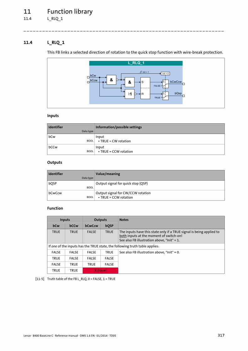
Lenze · 8400 BaseLine C · Reference manual · DMS 1.6 EN · 01/2014 · TD05 317
11 Function library11.4 L_RLQ_1
_ _ _ _ _ _ _ _ _ _ _ _ _ _ _ _ _ _ _ _ _ _ _ _ _ _ _ _ _ _ _ _ _ _ _ _ _ _ _ _ _ _ _ _ _ _ _ _ _ _ _ _ _ _ _ _ _ _ _ _ _ _ _ _
11.4 L_RLQ_1
This FB links a selected direction of rotation to the quick stop function with wire-break protection.
Inputs
Outputs
Function
[11-5] Truth table of the FB L_RLQ, 0 = FALSE, 1 = TRUE
IdentifierData type
Information/possible settings
bCwBOOL
Input• TRUE = CW rotation
bCCwBOOL
Input• TRUE = CCW rotation
IdentifierData type
Value/meaning
bQSPBOOL
Output signal for quick stop (QSP)
bCwCcwBOOL
Output signal for CW/CCW rotation• TRUE = CCW rotation
Inputs Outputs Notes
bCw bCCw bCwCcw bQSP
TRUE TRUE FALSE TRUE The inputs have this state only if a TRUE signal is being applied to both inputs at the moment of switch-on!See also FB illustration above, "Init" = 1.
If one of the inputs has the TRUE state, the following truth table applies:
FALSE FALSE FALSE TRUE See also FB illustration above, "Init" = 0.
TRUE FALSE FALSE FALSE
FALSE TRUE TRUE FALSE
TRUE TRUE X (save)
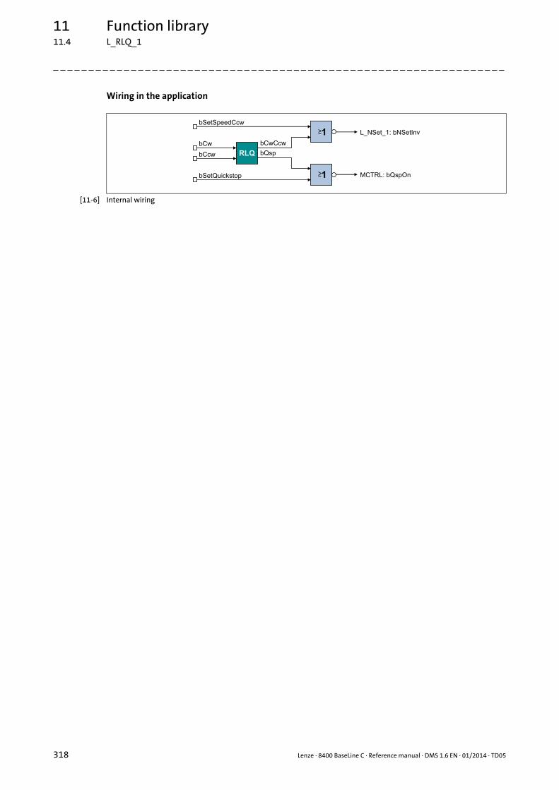
11 Function library11.4 L_RLQ_1
318 Lenze · 8400 BaseLine C · Reference manual · DMS 1.6 EN · 01/2014 · TD05
_ _ _ _ _ _ _ _ _ _ _ _ _ _ _ _ _ _ _ _ _ _ _ _ _ _ _ _ _ _ _ _ _ _ _ _ _ _ _ _ _ _ _ _ _ _ _ _ _ _ _ _ _ _ _ _ _ _ _ _ _ _ _ _
Wiring in the application
[11-6] Internal wiring
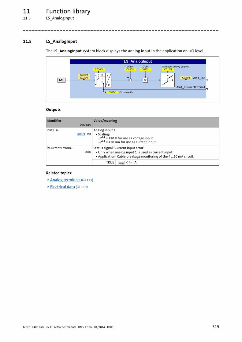
Lenze · 8400 BaseLine C · Reference manual · DMS 1.6 EN · 01/2014 · TD05 319
11 Function library11.5 LS_AnalogInput
_ _ _ _ _ _ _ _ _ _ _ _ _ _ _ _ _ _ _ _ _ _ _ _ _ _ _ _ _ _ _ _ _ _ _ _ _ _ _ _ _ _ _ _ _ _ _ _ _ _ _ _ _ _ _ _ _ _ _ _ _ _ _ _
11.5 LS_AnalogInput
The LS_AnalogInput system block displays the analog input in the application on I/O level.
Outputs
Related topics:
Analog terminals ( 111)
Electrical data ( 119)
IdentifierData type
Value/meaning
nIn1_aC033/1 | INT
Analog input 1• Scaling:
±214 ≡ ±10 V for use as voltage input+214 ≡ +20 mA for use as current input
bCurrentErrorIn1BOOL
Status signal "Current input error"• Only when analog input 1 is used as current input.• Application: Cable-breakage monitoring of the 4 ...20 mA circuit.
TRUE |IAIN1| < 4 mA

11 Function library11.6 LS_DigitalInput
320 Lenze · 8400 BaseLine C · Reference manual · DMS 1.6 EN · 01/2014 · TD05
_ _ _ _ _ _ _ _ _ _ _ _ _ _ _ _ _ _ _ _ _ _ _ _ _ _ _ _ _ _ _ _ _ _ _ _ _ _ _ _ _ _ _ _ _ _ _ _ _ _ _ _ _ _ _ _ _ _ _ _ _ _ _ _
11.6 LS_DigitalInput
The LS_DigitalInput system block displays the digital input terminals in the application on I/O level.
Outputs
Related topics:
Digital terminals ( 109)
Electrical data ( 119)
IdentifierDIS code | data type
Value/meaning
bCInhC443/2 | BOOL
RFR digital input (controller enable)
bIn1 ... bIn4C443/2 | BOOL
Digital input DI1 ... DI4
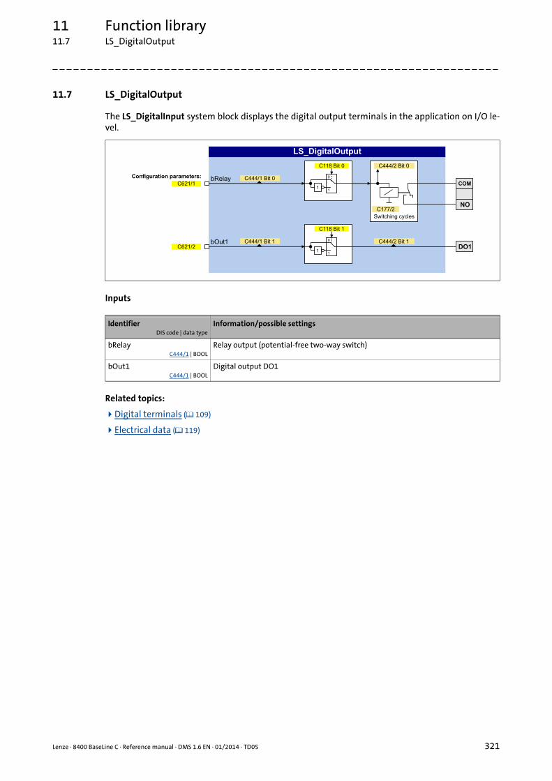
Lenze · 8400 BaseLine C · Reference manual · DMS 1.6 EN · 01/2014 · TD05 321
11 Function library11.7 LS_DigitalOutput
_ _ _ _ _ _ _ _ _ _ _ _ _ _ _ _ _ _ _ _ _ _ _ _ _ _ _ _ _ _ _ _ _ _ _ _ _ _ _ _ _ _ _ _ _ _ _ _ _ _ _ _ _ _ _ _ _ _ _ _ _ _ _ _
11.7 LS_DigitalOutput
The LS_DigitalInput system block displays the digital output terminals in the application on I/O le-vel.
Inputs
Related topics:
Digital terminals ( 109)
Electrical data ( 119)
IdentifierDIS code | data type
Information/possible settings
bRelayC444/1 | BOOL
Relay output (potential-free two-way switch)
bOut1C444/1 | BOOL
Digital output DO1

11 Function library11.8 LS_DisFree
322 Lenze · 8400 BaseLine C · Reference manual · DMS 1.6 EN · 01/2014 · TD05
_ _ _ _ _ _ _ _ _ _ _ _ _ _ _ _ _ _ _ _ _ _ _ _ _ _ _ _ _ _ _ _ _ _ _ _ _ _ _ _ _ _ _ _ _ _ _ _ _ _ _ _ _ _ _ _ _ _ _ _ _ _ _ _
11.8 LS_DisFree
This system block displays any four 16-bit signals of the application on display codes. The signals tobe displayed are selected via the given configuration parameters.
Inputs
Parameter
IdentifierData type
Information/possible settings
wDis1 ... wDis4WORD
Inputs for any 16-bit signals of the application
Parameter Possible settings Info
C481/1...4 0x0000 0xFFFF Display of the 16-bit signals at the wDis1 ... wDis4 inputs
C620/5...8 See selection list - analog signals Configuration parameters for the in-puts wDis1 ... wDis4
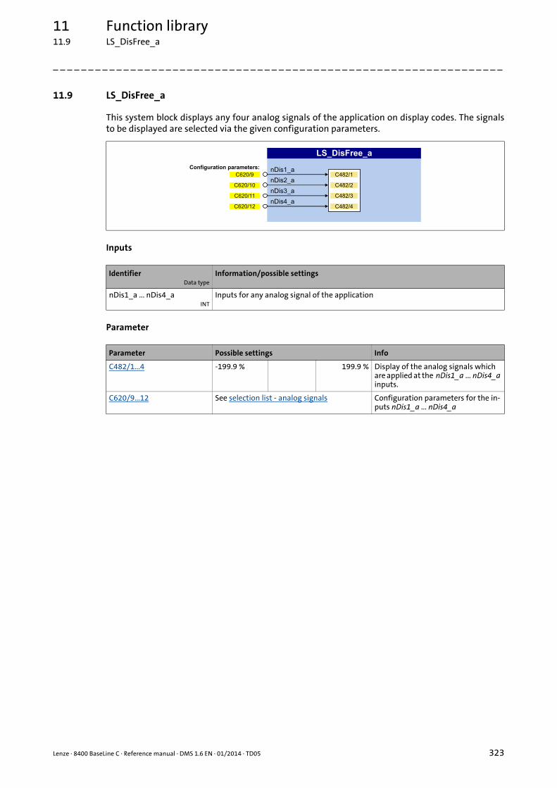
Lenze · 8400 BaseLine C · Reference manual · DMS 1.6 EN · 01/2014 · TD05 323
11 Function library11.9 LS_DisFree_a
_ _ _ _ _ _ _ _ _ _ _ _ _ _ _ _ _ _ _ _ _ _ _ _ _ _ _ _ _ _ _ _ _ _ _ _ _ _ _ _ _ _ _ _ _ _ _ _ _ _ _ _ _ _ _ _ _ _ _ _ _ _ _ _
11.9 LS_DisFree_a
This system block displays any four analog signals of the application on display codes. The signalsto be displayed are selected via the given configuration parameters.
Inputs
Parameter
IdentifierData type
Information/possible settings
nDis1_a ... nDis4_aINT
Inputs for any analog signal of the application
Parameter Possible settings Info
C482/1...4 -199.9 % 199.9 % Display of the analog signals which are applied at the nDis1_a ... nDis4_a inputs.
C620/9...12 See selection list - analog signals Configuration parameters for the in-puts nDis1_a ... nDis4_a

11 Function library11.10 LS_DisFree_b
324 Lenze · 8400 BaseLine C · Reference manual · DMS 1.6 EN · 01/2014 · TD05
_ _ _ _ _ _ _ _ _ _ _ _ _ _ _ _ _ _ _ _ _ _ _ _ _ _ _ _ _ _ _ _ _ _ _ _ _ _ _ _ _ _ _ _ _ _ _ _ _ _ _ _ _ _ _ _ _ _ _ _ _ _ _ _
11.10 LS_DisFree_b
This system block displays any eight digital signals of the application on a bit-coded display code.The signals to be displayed are selected via the given configuration parameters.
Inputs
Parameter
IdentifierData type
Information/possible settings
bDis1 ... bDis8BOOL
Inputs for any digital signal of the application
Parameter Possible settings Info
C480 0x0000 0xFFFF Display of the digital signals applied at the bDis1 ... bDis8 inputs in the form of hexadecimal valuesBit 0 Signal level at the bDis1 input
Bit 1 Signal level at the bDis2 input
Bit 2 Signal level at the bDis3 input
... ...
Bit 7 Signal level at the bDis8 input
C621/16...23 See selection list - digital signals Configuration parameters for the in-puts bDis1 ... bDis8

Lenze · 8400 BaseLine C · Reference manual · DMS 1.6 EN · 01/2014 · TD05 325
11 Function library11.11 LS_DriveInterface
_ _ _ _ _ _ _ _ _ _ _ _ _ _ _ _ _ _ _ _ _ _ _ _ _ _ _ _ _ _ _ _ _ _ _ _ _ _ _ _ _ _ _ _ _ _ _ _ _ _ _ _ _ _ _ _ _ _ _ _ _ _ _ _
11.11 LS_DriveInterface
The LS_DriveInterface system block displays the device control in the application.

11 Function library11.11 LS_DriveInterface
326 Lenze · 8400 BaseLine C · Reference manual · DMS 1.6 EN · 01/2014 · TD05
_ _ _ _ _ _ _ _ _ _ _ _ _ _ _ _ _ _ _ _ _ _ _ _ _ _ _ _ _ _ _ _ _ _ _ _ _ _ _ _ _ _ _ _ _ _ _ _ _ _ _ _ _ _ _ _ _ _ _ _ _ _ _ _
Inputs
IdentifierDIS code | data type
Information/possible settings
wCANControlC136/1 | WORD
Control word via system bus (CAN)• In the control mode "30: CAN", the controller controlled by a master control (e.g.
IPC) receives its control word by the CANopen system bus interface. The process data word is provided at this input by the upstream port block LP_CanIn1.
• See the "Process data assignment for control via CAN" chapter for a detailed de-scription of the individual control bits.
bCInhC833/14 | BOOL
Enable/Inhibit controller
FALSE Enable controller: The controller switches to the "OperationEnabled" device state, if no other source of a controller inhibit is active.
• C158 provides a bit coded representation of all active sour-ces/triggers of a controller inhibit.
TRUE Inhibit controller (controller inhibit): The controller switches to the "SwitchedON" device state.
bFailResetC833/15 | BOOL
Reset of error messageIn the Lenze setting this input is connected to the digital input controller enable so that a possibly existing error message is reset together with the controller enable (if the cause for the fault is eliminated).
TRUE The current fault is reset, if the cause for the fault is eliminated.• If the fault still exists, the error status remains unchanged.
bStatus_Bit0bStatus_Bit2bStatus_Bit3bStatus_Bit4bStatus_Bit5bStatus_Bit14bStatus_Bit15
C833/16 ... 22 | BOOL
Freely assignable bits in the status word of the controller.• You can use these bits for returning information to the master control (e.g. IPC).
Pre-assignment in the Lenze setting:
Bit0 - (Not connected)
Bit2 Current setpoint in the limitation
Bit3 Speed setpoint reached
Bit4 Actual speed value has reached the setpoint within one hysteresis band
Bit5 Speed setpoint < comparison value (C024)
Bit14 Current direction of rotation:0 ≡ Clockwise rotation (Cw)1 ≡ Counter-clockwise rotation (Ccw)
Bit15 Drive is ready for operation
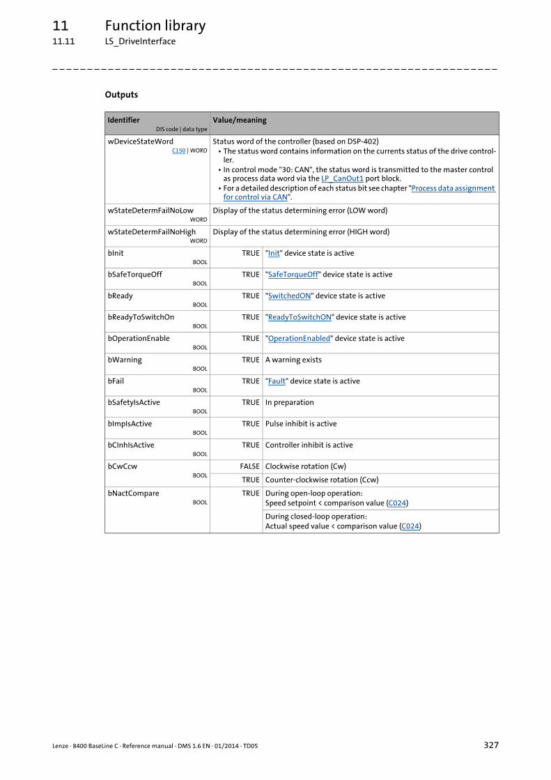
Lenze · 8400 BaseLine C · Reference manual · DMS 1.6 EN · 01/2014 · TD05 327
11 Function library11.11 LS_DriveInterface
_ _ _ _ _ _ _ _ _ _ _ _ _ _ _ _ _ _ _ _ _ _ _ _ _ _ _ _ _ _ _ _ _ _ _ _ _ _ _ _ _ _ _ _ _ _ _ _ _ _ _ _ _ _ _ _ _ _ _ _ _ _ _ _
Outputs
IdentifierDIS code | data type
Value/meaning
wDeviceStateWordC150 | WORD
Status word of the controller (based on DSP-402)• The status word contains information on the currents status of the drive control-
ler.• In control mode "30: CAN", the status word is transmitted to the master control
as process data word via the LP_CanOut1 port block.• For a detailed description of each status bit see chapter "Process data assignment
for control via CAN".
wStateDetermFailNoLowWORD
Display of the status determining error (LOW word)
wStateDetermFailNoHighWORD
Display of the status determining error (HIGH word)
bInitBOOL
TRUE "Init" device state is active
bSafeTorqueOffBOOL
TRUE "SafeTorqueOff" device state is active
bReadyBOOL
TRUE "SwitchedON" device state is active
bReadyToSwitchOnBOOL
TRUE "ReadyToSwitchON" device state is active
bOperationEnableBOOL
TRUE "OperationEnabled" device state is active
bWarningBOOL
TRUE A warning exists
bFailBOOL
TRUE "Fault" device state is active
bSafetyIsActiveBOOL
TRUE In preparation
bImpIsActiveBOOL
TRUE Pulse inhibit is active
bCInhIsActiveBOOL
TRUE Controller inhibit is active
bCwCcwBOOL
FALSE Clockwise rotation (Cw)
TRUE Counter-clockwise rotation (Ccw)
bNactCompareBOOL
TRUE During open-loop operation:Speed setpoint < comparison value (C024)
During closed-loop operation:Actual speed value < comparison value (C024)
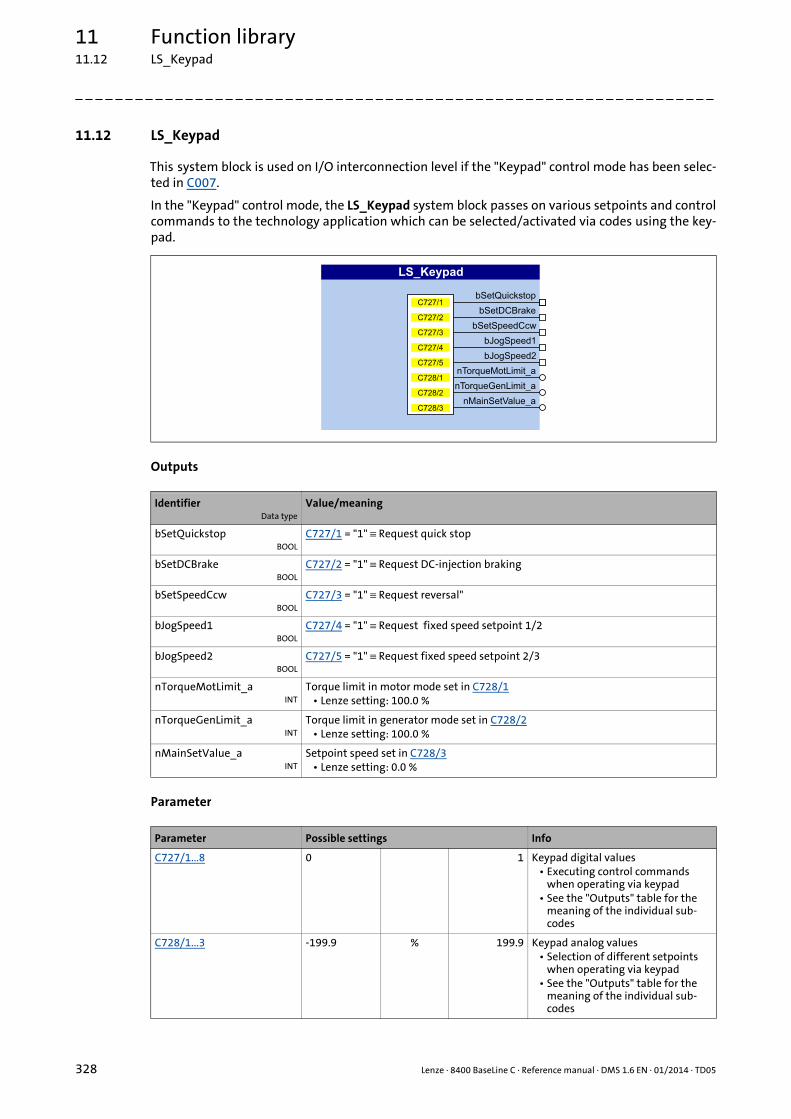
11 Function library11.12 LS_Keypad
328 Lenze · 8400 BaseLine C · Reference manual · DMS 1.6 EN · 01/2014 · TD05
_ _ _ _ _ _ _ _ _ _ _ _ _ _ _ _ _ _ _ _ _ _ _ _ _ _ _ _ _ _ _ _ _ _ _ _ _ _ _ _ _ _ _ _ _ _ _ _ _ _ _ _ _ _ _ _ _ _ _ _ _ _ _ _
11.12 LS_Keypad
This system block is used on I/O interconnection level if the "Keypad" control mode has been selec-ted in C007.
In the "Keypad" control mode, the LS_Keypad system block passes on various setpoints and controlcommands to the technology application which can be selected/activated via codes using the key-pad.
Outputs
Parameter
IdentifierData type
Value/meaning
bSetQuickstopBOOL
C727/1 = "1" ≡ Request quick stop
bSetDCBrakeBOOL
C727/2 = "1" ≡ Request DC-injection braking
bSetSpeedCcwBOOL
C727/3 = "1" ≡ Request reversal"
bJogSpeed1BOOL
C727/4 = "1" ≡ Request fixed speed setpoint 1/2
bJogSpeed2BOOL
C727/5 = "1" ≡ Request fixed speed setpoint 2/3
nTorqueMotLimit_aINT
Torque limit in motor mode set in C728/1• Lenze setting: 100.0 %
nTorqueGenLimit_aINT
Torque limit in generator mode set in C728/2• Lenze setting: 100.0 %
nMainSetValue_aINT
Setpoint speed set in C728/3• Lenze setting: 0.0 %
Parameter Possible settings Info
C727/1...8 0 1 Keypad digital values• Executing control commands
when operating via keypad• See the "Outputs" table for the
meaning of the individual sub-codes
C728/1...3 -199.9 % 199.9 Keypad analog values• Selection of different setpoints
when operating via keypad• See the "Outputs" table for the
meaning of the individual sub-codes

Lenze · 8400 BaseLine C · Reference manual · DMS 1.6 EN · 01/2014 · TD05 329
11 Function library11.13 LS_ParFix
_ _ _ _ _ _ _ _ _ _ _ _ _ _ _ _ _ _ _ _ _ _ _ _ _ _ _ _ _ _ _ _ _ _ _ _ _ _ _ _ _ _ _ _ _ _ _ _ _ _ _ _ _ _ _ _ _ _ _ _ _ _ _ _
11.13 LS_ParFix
This system block outputs various fixed values (constants) to be used in the interconnection. Theconstants can be assigned to other inputs via configuration parameters.
Outputs
Related topics:
User-defined terminal assignment ( 114)
IdentifierData type
Value/meaning
C_bTrueBOOL
1 ≡ TRUE
C_nPos100_aINT
16384 ≡ + 100 %
C_nNeg100_aINT
-16384 ≡ - 100 %
C_nPos199_9_aINT
32767 ≡ + 199.9 %
C_nNeg199_9_aINT
-32767 ≡ - 199.9 %
C_w65535WORD
65535 ≡ 0xFFFF
C_wDriveCtrlWORD
9 ≡ 0x0009• Bit 0, SwitchOn = TRUE• Bit 3, EnableOperation = TRUE• All others: FALSE
See also:Process data assignment for control via CAN ( 137)
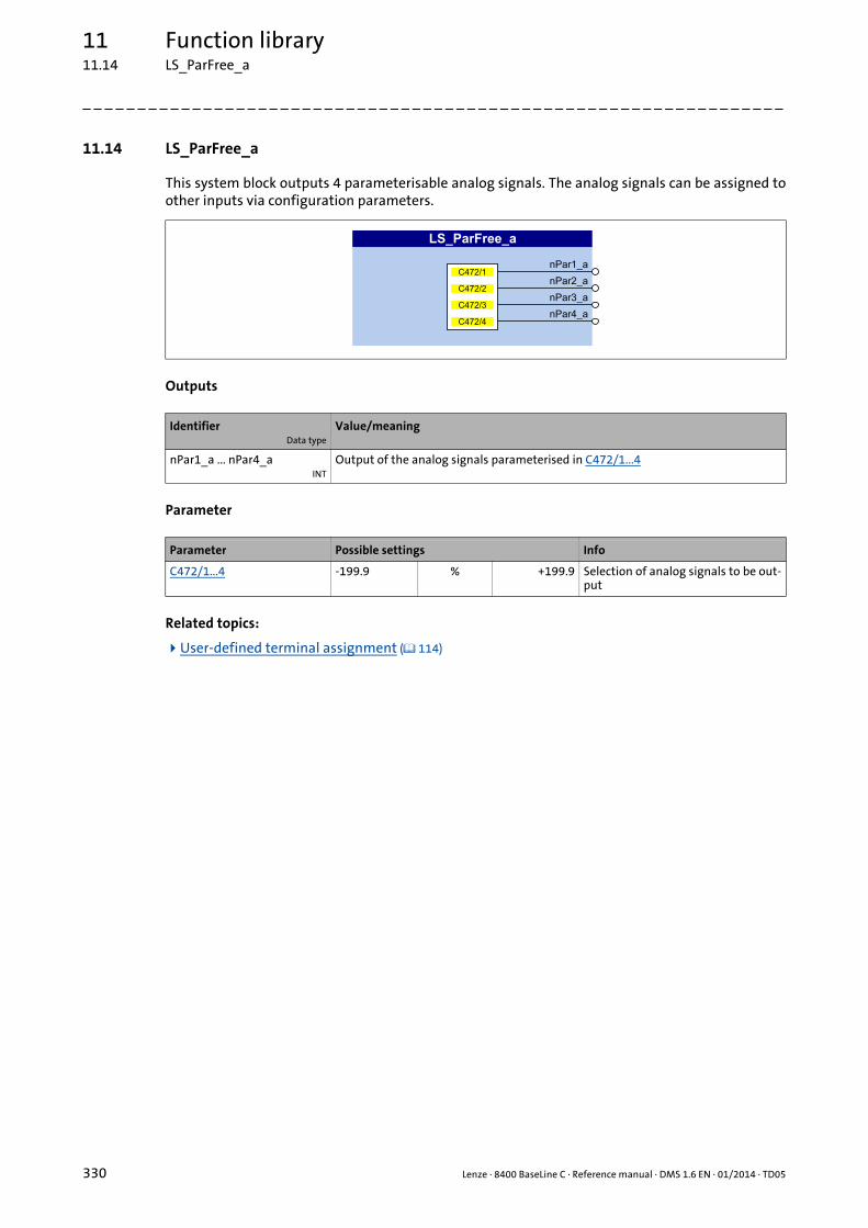
11 Function library11.14 LS_ParFree_a
330 Lenze · 8400 BaseLine C · Reference manual · DMS 1.6 EN · 01/2014 · TD05
_ _ _ _ _ _ _ _ _ _ _ _ _ _ _ _ _ _ _ _ _ _ _ _ _ _ _ _ _ _ _ _ _ _ _ _ _ _ _ _ _ _ _ _ _ _ _ _ _ _ _ _ _ _ _ _ _ _ _ _ _ _ _ _
11.14 LS_ParFree_a
This system block outputs 4 parameterisable analog signals. The analog signals can be assigned toother inputs via configuration parameters.
Outputs
Parameter
Related topics:
User-defined terminal assignment ( 114)
IdentifierData type
Value/meaning
nPar1_a ... nPar4_aINT
Output of the analog signals parameterised in C472/1...4
Parameter Possible settings Info
C472/1...4 -199.9 % +199.9 Selection of analog signals to be out-put

Lenze · 8400 BaseLine C · Reference manual · DMS 1.6 EN · 01/2014 · TD05 331
11 Function library11.15 LS_ParFree_b
_ _ _ _ _ _ _ _ _ _ _ _ _ _ _ _ _ _ _ _ _ _ _ _ _ _ _ _ _ _ _ _ _ _ _ _ _ _ _ _ _ _ _ _ _ _ _ _ _ _ _ _ _ _ _ _ _ _ _ _ _ _ _ _
11.15 LS_ParFree_b
This system block outputs 16 parameterisable digital signals. The digital signals can be assigned toother inputs via configuration parameters.
Outputs
Parameter
Related topics:
User-defined terminal assignment ( 114)
IdentifierData type
Value/meaning
bPar1 ... bPar16BOOL
Output of the signals levels (FALSE/TRUE) parameterised in C470/1...16
Parameter Possible settings Info
C470/1...16 Selection of signal levels to be output• Bit 0 ... 15 = bPar1 ... bPar160 "FALSE" signal is output
1 "TRUE" signal is output
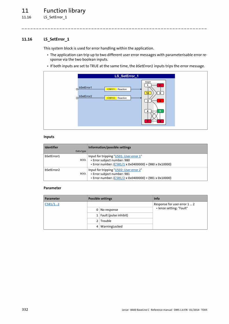
11 Function library11.16 LS_SetError_1
332 Lenze · 8400 BaseLine C · Reference manual · DMS 1.6 EN · 01/2014 · TD05
_ _ _ _ _ _ _ _ _ _ _ _ _ _ _ _ _ _ _ _ _ _ _ _ _ _ _ _ _ _ _ _ _ _ _ _ _ _ _ _ _ _ _ _ _ _ _ _ _ _ _ _ _ _ _ _ _ _ _ _ _ _ _ _
11.16 LS_SetError_1
This system block is used for error handling within the application.
• The application can trip up to two different user error messages with parameterisable error re-sponse via the two boolean inputs.
• If both inputs are set to TRUE at the same time, the bSetError1 inputs trips the error message.
Inputs
Parameter
IdentifierData type
Information/possible settings
bSetError1BOOL
Input for tripping "US01: User error 1"• Error subject number: 980• Error number: (C581/1 x 0x0400000) + (980 x 0x10000)
bSetError2BOOL
Input for tripping "US02: User error 2"• Error subject number: 981• Error number: (C581/2 x 0x0400000) + (981 x 0x10000)
Parameter Possible settings Info
C581/1...2 Response for user error 1 ... 2• lenze setting: "Fault"0 No response
1 Fault (pulse inhibit)
2 Trouble
4 WarningLocked

Lenze · 8400 BaseLine C · Reference manual · DMS 1.6 EN · 01/2014 · TD05 333
Index
_ _ _ _ _ _ _ _ _ _ _ _ _ _ _ _ _ _ _ _ _ _ _ _ _ _ _ _ _ _ _ _ _ _ _ _ _ _ _ _ _ _ _ _ _ _ _ _ _ _ _ _ _ _ _ _ _ _ _ _ _ _ _ _
Numbers16-bit analog input (C00830) 292
16-bit system connection (C00620) 285
16Bit-Input common (C00831) 292
87-Hz operation 83
8-bit input (C00833) 293
AAcceleration time main setpoint (C00012) 239
Acknowledgement error 206
Activating the bus terminating resistor 173
Active COBID (C00355) 271
AINxConfiguration (C00034) 243Gain (C00027) 242Input current (C00029) 243Input voltage (C00028) 242Offset (C00026) 242Output value (C00033) 243
An01AIN1_I < 4 mA (error message) 163
Analog inputs 111
Appl.Reference frequency C11 (C00059) 246Reference speed (C00011) 239
Application notes 11
Assignment of the process data objects 184
Auto-DCB 97Hold time (C00106) 251Threshold (C00019) 241
Automatic DC-injection braking (Auto-DCB) 97
Automatic motor data identification 70
Automatic saving 49
Auto-start option (C00142) 256
BBit error 206
Blocks 304
Bool system connection (C00621) 286
Brake chopper 101
Brake resistor 101
Brake resistor monitoring (I2xt) 106
Braking operation 101
CC10 239
C100 250
C105 251
C106 251
C107 251
C11 239
C114 252
C118 252
C12 239, 310
C120 253
C122 253
C123 253
C13 239, 310
C134 253, 310
C136 254
C137 255
C141 255
C142 256
C144 256
C15 240
C150 257
C155 258
C158 259
C159 260
C16 240
C165 260
C166 260
C167 261
C168 261
C169 261
C170 261
C171 261
C173 262
C174 262
C177 262
C178 262
C179 262
C18 240
C182 263, 310
C19 241
C2 235
C200 263
C201 263
C203 263
C21 241
C22 241
C222 263, 313
C223 264, 313
C224 264, 313
C225 264, 313
C226 264, 313
C227 264, 313
C228 265, 313
C23 241
C231 265, 314
C234 265
C235 265
C236 265
C24 242
C242 266, 314
C243 266, 314
C244 266, 314
Index
Index
334 Lenze · 8400 BaseLine C · Reference manual · DMS 1.6 EN · 01/2014 · TD05
_ _ _ _ _ _ _ _ _ _ _ _ _ _ _ _ _ _ _ _ _ _ _ _ _ _ _ _ _ _ _ _ _ _ _ _ _ _ _ _ _ _ _ _ _ _ _ _ _ _ _ _ _ _ _ _ _ _ _ _ _ _ _ _
C245 266, 314
C26 242
C27 242
C28 242
C29 243
C3 237
C308 266
C309 267
C322 267
C323 267
C324 268
C33 243
C34 243
C345 268
C347 269
C350 269
C351 269
C352 270
C353 270
C354 270
C355 271
C356 271
C357 271
C359 272
C36 244
C360 272
C364 273
C366 273
C367 273
C368 274
C369 274
C372 274
C381 274
C385 275
C386 275
C389 275
C39 244, 310
C409 276
C443 277
C444 278
C462 278
C470 278, 331
C472 279, 330
C480 279, 324
C481 279, 322
C482 280, 323
C50 244
C51 244
C516 280
C517 281
C52 245
C53 245
C54 245
C56 245
C565 281
C57 245
C574 282
C58 246
C581 282
C59 246
C592 282
C593 283
C594 283
C598 283
C6 237
C600 284
C601 284
C604 284
C606 284
C61 246
C620 285
C621 286
C64 246
C66 247
C7 238
C700 288
C701 289
C725 289
C727 290, 328
C728 290, 328
C729 290
C73 247
C74 247
C800 290, 306
C801 290, 306
C802 291, 306
C803 291, 306
C804 291, 306, 308
C805 291
C806 292, 307
C81 247
C830 292
C831 292
C833 293
C84 247
C85 248
C866 294
C868 295
C87 248
C88 248
C89 248
C90 249
C909 295
C91 249
C910 296
C92 249

Lenze · 8400 BaseLine C · Reference manual · DMS 1.6 EN · 01/2014 · TD05 335
Index
_ _ _ _ _ _ _ _ _ _ _ _ _ _ _ _ _ _ _ _ _ _ _ _ _ _ _ _ _ _ _ _ _ _ _ _ _ _ _ _ _ _ _ _ _ _ _ _ _ _ _ _ _ _ _ _ _ _ _ _ _ _ _ _
C93 249
C94 249
C95 250
C97 250
C98 250
C99 250
C990 296
C991 296
C992 296
C994 297
CA06CAN CRC error (error message) 164
CA07CAN bus warning (error message) 164
CA08CAN bus stopped (error message) 164
CA0bCAN Bus Live Time (error message) 164
CA0FCAN control word (error message) 165
CAN baud rate (C00351) 269
CAN data telegram 176
CAN error status (C00345) 268
CAN Heartbeat Producer Time (C00381) 274
CAN IN/OUT COBID source (C00353) 270
CAN input words (C00866) 294
CAN MessageError (C00364) 273
CAN monitoring times (C00357) 271
CAN node address (C00350) 269
CAN NodeID Heartbeat producer (C00385) 275
CAN on board 169
CAN output words (C00868) 295
CAN Slave/Master (C00352) 270
CAN start remote node 182
CAN status (C00359) 272
CAN status HeartBeat producer (C00347) 269
CAN Sync transmission cycle time (C00369) 274
CAN Sync-Rx-Identifier (C00367) 273
CAN Sync-Tx identifier (C00368) 274
CAN telegram counter (C00360) 272
CAN time settings (C00356) 271
CAN transmit blocking time (C00324) 268
CAN_Tx_Rx_Error (C00372) 274
Cause for controller inhibit (C00158) 259
Cause for quick stop QSP (C00159) 260
CE1CAN RPDO1 (error message) 165
CE2CAN RPDO2 (error message) 165
CE4CAN bus off (error message) 164
Checksums (C00516) 280
COB-ID 176
COBID (C00354) 270
COB-ID EMCY (I-1014) 216
COB-ID SYNC message (I-1005) 215
Communication control words (C00136) 254
Communication cycle period (I-1006) 216
Communication time 172
Comparison value N_Act (C00024) 242
Consumer heartbeat time (I-1016) 217
ConsumerTime HeartBeat Producer (C00386) 275
Control mode 73
Control mode (C00007) 238
Conventions used 9
CRC error 206
Current switching frequency (C00725) 289
DData type 230
DCBCurrent (C00036) 244Hold time (C00107) 251
DCB (DC-injection braking) 97
DC-bus voltage (C00053) 245
DC-injection braking 96
Deceleration time main setpoint (C00013) 239
Deceleration time quick stop (C00105) 251
Defining current limits 76
Defining speed limits 76
Delayed resp. to faultDC bus overvoltage (C00601) 284
Device commands (C00002) 235
Device overload monitoring (Ixt) 103
Device rated current (C00098) 250
Device settings (C00141) 255
Device state (C00137) 255
Device type (I-1000) 213
Device utilisation (Ixt) (C00064) 246
Device utilisation threshold (Ixt) (C00123) 253
dF01Internal error 01 (error message) 166
dF02Internal error 02 (error message) 166
dF03Internal error 03 (error message) 167
dF04Internal error 04 (error message) 167
dF05Internal error 05 (error message) 167
dF06Internal error 06 (error message) 167
dF07Internal error 07 (error message) 167
dF08Internal error 08 (error message) 168
dF09Internal error 09 (error message) 168
Index
336 Lenze · 8400 BaseLine C · Reference manual · DMS 1.6 EN · 01/2014 · TD05
_ _ _ _ _ _ _ _ _ _ _ _ _ _ _ _ _ _ _ _ _ _ _ _ _ _ _ _ _ _ _ _ _ _ _ _ _ _ _ _ _ _ _ _ _ _ _ _ _ _ _ _ _ _ _ _ _ _ _ _ _ _ _ _
dF10Internal error 10 (error message) 168
dH69Adjustment fault (error message) 168
Digital input assignment 289
Digital inputs 109
Digital outputs 109
Digital terminals 109
DIxLevel (C00443) 277
DIx inversion (C00114) 252
DOxLevel (C00444) 278
DOx inversion (C00118) 252
Drive interface 44
EElapsed-hour meter (C00178) 262
Electrical data I/O terminals 119
E-mail to Lenze 340
Emergency 210
Error counter (C00170) 261
Error detection 206
Error ID 157
Error information (C00165) 260
Error information text (C00166) 260
Error messages 156
Error messages (short overview) 159
Error messages (system bus) 199
Error number 156xx.0111.00002 161xx.0119.00001 161xx.0119.00050 161xx.0119.00052 162xx.0123.00014 162xx.0123.00015 162xx.0123.00016 162xx.0123.00017 163xx.0123.00057 163xx.0123.00065 163xx.0123.00105 163xx.0125.00001 163xx.0131.00000 164xx.0131.00006 164xx.0131.00007 164xx.0131.00008 164xx.0131.00011 164xx.0131.00015 165xx.0135.00001 165xx.0135.00002 165xx.0144.00001 165xx.0144.00002 165xx.0144.00003 166xx.0144.00004 166xx.0144.00031 166xx.0145.00001 166
xx.0145.00002 166xx.0145.00003 167xx.0145.00004 167xx.0145.00005 167xx.0145.00006 167xx.0145.00007 167xx.0145.00008 168xx.0145.00009 168xx.0145.00010 168xx.0400.00105 168xx.0980.00000 168xx.0981.00000 168
Error number (C00168) 261
Error register (I-1001) 213
Error subject area 157
Error type 156
Exporting logbook entries 150
FFeedback to Lenze 340
Firmware compile date (C00201) 263
Firmware product type (C00200) 263
Firmware version (C00099) 250
Firmware version (C00100) 250
Fixed setpoint x (L_NSet_1 n-Fix) (C00039) 244
Flying restart fct. 94Activation (C00990) 296Current (C00994) 297Process (C00991) 296Start frequency (C00992) 296
Format error 206
Frequency limitation (C00910) 296
Function assignment 289
Function blocks 304
Function library 304
GGeneral data (CAN on board) 171
HHeartbeat protocol 207
Heatsink temperature (C00061) 246
II-1000 213
I-1001 213
I-1003 214
I-1005 215
I-1006 216
I-1014 216
I-1016 217
I-1017 217
I-1018 218
I-1200 218
I-1201 219
Lenze · 8400 BaseLine C · Reference manual · DMS 1.6 EN · 01/2014 · TD05 337
Index
_ _ _ _ _ _ _ _ _ _ _ _ _ _ _ _ _ _ _ _ _ _ _ _ _ _ _ _ _ _ _ _ _ _ _ _ _ _ _ _ _ _ _ _ _ _ _ _ _ _ _ _ _ _ _ _ _ _ _ _ _ _ _ _
I-1400 221
I-1401 222
I-1600 223
I-1601 223
I-1800 224
I-1801 226
I-1A00 227
I-1A01 227
ID1Motor data identification error (error message) 163
Identifier (CAN) 176
Identifiers of the parameter data objects 195
Identifiers of the process data objects 189
Identity object (I-1018) 218
Imax controller 81
Imax in generator mode (C00023) 241
Imax in motor mode (C00022) 241
Initial value motor overload (I²xt) (C00122) 253
Integrated error detection 206
Interconnection"Terminals 0" control mode 135Control mode "CAN" 136
Internal wiring"Terminals 0" control mode 135Control mode "CAN" 136
LL_MPot 305
L_MPot_1 305Acceleration time (C00802) 291Deceleration time (C00803) 291Inactive fct. (C00804) 291Init fct. (C00805) 291Lower limit (C00801) 290Upper limit (C00800) 290Use (C00806) 292
L_NSet 309
L_NSet_1 309
L_PCTRL 312
L_PCTRL_1 312Acceleration time (C00227) 264Acceleration time influence (C00243) 266Deceleration time (C00228) 265Deceleration time influence (C00244) 266Kd (C00224) 264MaxLimit (C00225) 264MinLimit (C00226) 264Operating mode (C00242) 266Operating range (C00231) 265PID output value (C00245) 266Tn (C00223) 264Vp (C00222) 263
L_RLQ 317
L_RLQ_1 317
LA_NCtrlAnalog connection list (C00700) 288Digital connection list (C00701) 289
Layout of the safety instructions 11
LED status display 18
Library 304
LP_CanIn Mapping (C00409) 276
LP_CanIn1 185
LP_CanIn2 186
LP_CanOut1 187
LP_CanOut2 188
LS_AnalogInput 319
LS_DigitalInput 320
LS_DigitalOutput 321
LS_DisFree 322
LS_DisFree (C00481) 279
LS_DisFree_a 323
LS_DisFree_a (C00482) 280
LS_DisFree_b 324
LS_DisFree_b (C00480) 279
LS_DriveInterface 325
LS_Keypad 328digital values (C00727) 290Keypad analog values (C00728) 290
LS_ParFix 329
LS_ParFree_a 330
LS_ParFree_a (C00472) 279
LS_ParFree_b 331
LS_ParFree_b (C00470) 278
LS_SetError_1 332
LUDC bus undervoltage (error message) 162
MMains phase failure monitoring 107
Mains voltage (C00173) 262
Manual DC-injection braking (DCB) 97
Master functionality (CAN) 182
Maximum torque (C00057) 245
MCTRLActual speed value (C00051) 244Speed setpoint (C00050) 244
Minimum analog setpoint (C00010) 239
Monitoring 103, 151
Motor catalogue 68
Motor control 6487-Hz operation 83DC-injection braking 96Flying restart fct. 94Oscillation damping 100Selection help 75Selection of switching frequency 92Selection of the control mode 73Sensorless vector control (SLVC) 87Slip compensation 99

Index
338 Lenze · 8400 BaseLine C · Reference manual · DMS 1.6 EN · 01/2014 · TD05
_ _ _ _ _ _ _ _ _ _ _ _ _ _ _ _ _ _ _ _ _ _ _ _ _ _ _ _ _ _ _ _ _ _ _ _ _ _ _ _ _ _ _ _ _ _ _ _ _ _ _ _ _ _ _ _ _ _ _ _ _ _ _ _
V/f characteristic control (VFCplus) 78
Motor control (C00006) 237
Motor cosine phi (C00091) 249
Motor current (C00054) 245
Motor data 65
Motor load monitoring (I2xt) 104
Motor magnetising current (C00095) 250
Motor magnetising inductance (C00092) 249
Motor overload threshold (I²xt) (C00120) 253
Motor parameter identification 70
Motor parameter identification is active 56
Motor selection 65
Motor stator leakage inductance (C00085) 248
Motor stator resistance (C00084) 247
Motor voltage (C00052) 245
NNetwork management telegram (NMT) 181
NMT (network management) 181
Node address 176
Node ID 176
Number of CAN SDO channels (C00366) 273
OOC1
Power section - short circuit (error message) 162
OC12I2xt overload - brake resistor (error message) 163
OC2Power section - earth fault (error message) 163
OC5Ixt overload (error message) 161
OC6I2xt overload - motor (error message) 163
OC9Ixt overload - shutdown limit (error message) 162
OHHeatsink overtemperature (error message) 161
Operating conditions (CAN on board) 171
Oscillation damping 100
Oscillation damping influence (C00234) 265
OUDC bus overvoltage (error message) 162
Output frequency (C00058) 246
PPassword (C00094) 249
Password protection 23
PC manual control 39
PDO mapping 185, 186
PDO synchronisation 192
PDO valid / invalid (C00389) 275
Peak current limitation 76
Plant parameters 69
Port block "LP_CanIn1" 185
Port block "LP_CanIn2" 186
Port block "LP_CanOut1" 187
Port block "LP_CanOut2" 188
Power section identification (C00093) 249
Power-on time meter (C00179) 262
Pre-defined error field (I-1003) 214
Process data objects, identifiers 189
Processing time 172
Producer heartbeat time (I-1017) 217
Product type code (C00203) 263
PS01No memory module (error message) 165
PS02Par. set invalid (error message) 165
PS03Par. set device invalid (error message) 166
PS04Par. set device incompatible (error message) 166
PS31Ident. error (error message) 166
RRamp smoothing, main setpoint (C00134) 253
Rated motor current (C00088) 248
Rated motor frequency (C00089) 248
Rated motor power (C00081) 247
Rated motor speed (C00087) 248
Rated motor torque (C00097) 250
Rated motor voltage (C00090) 249
Reduced brake chopper threshold (C00174) 262
Reset of error message 158
Resp. to brake resist. overtemp. (C00574) 282
Resp. to CAN bus connection (C00592) 282
Resp. to CANx_IN monitoring (C00593) 283
Resp. to control word error (C00594) 283
Resp. to DC bus undervoltage (C00600) 284
Resp. to device overload (Ixt) (C00604) 284
Resp. to LS_SetError_x (C00581) 282
Resp. to mains phase failure (C00565) 281
Resp. to motor overload (I²xt) (C00606) 284
Resp. to open circuit AINx (C00598) 283
RPDO1 communication parameter (I-1400) 221
RPDO1 mapping parameter (I-1600) 223
RPDO2 communication parameter (I-1401) 222
RPDO2 mapping parameter (I-1601) 223
SSafety instructions 11
Save parameter settings 49
Saving parameters automatically 49
SDO1 server parameter (I-1200) 218
SDO2 server parameter (I-1201) 219
Selection help for motor control 75

Lenze · 8400 BaseLine C · Reference manual · DMS 1.6 EN · 01/2014 · TD05 339
Index
_ _ _ _ _ _ _ _ _ _ _ _ _ _ _ _ _ _ _ _ _ _ _ _ _ _ _ _ _ _ _ _ _ _ _ _ _ _ _ _ _ _ _ _ _ _ _ _ _ _ _ _ _ _ _ _ _ _ _ _ _ _ _ _
Selection of switching frequency 92
Selection of the control mode 73
Sensorless vector control (SLVC) 74, 87
Setting the baud rate 173
Setting the error response 153
Setting the node address 173
Short overview of error messages 159
Signal flowV/f characteristic control (VFCplus) 78V/f control (VFCplus + encoder) 88
Signal source assignment 289
Slip comp. (C00021) 241
Slip compensation 99
Speed control with torque limitation (SLVC) 89
Speed limitation (C00909) 295
S-ramp time PT1 (C00182) 263
Status of last device command (C00003) 237
Status word (C00150) 257
Status word 2 (C00155) 258
Stuff-bit error 206
Su02One mains phase is missing (error message) 161
Switching cycles (C00177) 262
Switching frequency 92
Switching frequency (C00018) 240
Switching frequency reduction (temp.) (C00144) 256
Sync telegram 192
System blocks 304
System bus 169
System error messages 156
TThermal motor load (I²xt) (C00066) 247
Ti Imax controller (C00074) 247
Time of error (C00169) 261
Torque (C00056) 245
Torque limitation 85
TPDO1 communication parameter (I-1800) 224
TPDO1 mapping parameter (I-1A00) 227
TPDO2 communication parameter (I-1801) 226
TPDO2 mapping parameter (I-1A01) 227
Transmission mode CAN Rx PDOs (C00323) 267
Transmission mode CAN TxPDOs (C00322) 267
Transmission type 190
UUS01
User error 1 (error message) 168
US02User error 2 (error message) 168
User data 195
User menu 22
User menu (C00517) 281
VV/f base frequency 83
V/f characteristic control (VFCplus) 74, 78
VFCV/f base frequency (C00015) 240Vmin boost (C00016) 240
Vmin boost 84
Vp Imax controller (C00073) 247

340
Your opinion is important to usThese instructions were created to the best of our knowledge andbelief to give you the best possible support for handling our product.
If you have suggestions for improvement, please e-mail us to:
Thank you for your support.
Your Lenze documentation team

341

L
8400 BaseLine C · Reference manual · EDS84AVBCxx · 13295753 · DMS 1.6 EN · 01/2014 · TD05
Lenze AC Tech Corporation630 Douglas StreetUxbridge, MA 01569USA
+1 508 / 278-9100+1 508 / [email protected]
ServiceLenze Service GmbHBreslauer Straße 3D-32699 ExtertalGermany
00 80 00 / 24 4 68 77 (24 h helpline)+49 (0)51 54 / 82-11 [email protected]


