
PRIMERGY
PRIMERGY RX220 Serversystem Options GuideMonika SpanjaartFujitsu Siemens Computers GmbH Muenchen33094 Paderborne-mail: email: [email protected].: Fax: 0 700 / 372 00001RX220Sprachen: En
Edition September 2005

Comments… Suggestions… Corrections…The User Documentation Department would like toknow your opinion of this manual. Your feedback helpsus optimize our documentation to suit your individual needs.
Fax forms for sending us your comments are included inthe back of the manual.
There you will also find the addresses of the relevantUser Documentation Department.
Certified documentation according to DIN EN ISO 9001:2000To ensure a consistently high quality standard anduser-friendliness, this documentation was created tomeet the regulations of a quality management system which complies with the requirements of the standardDIN EN ISO 9001:2000.
cognitas. Gesellschaft für Technik-Dokumentation mbHwww.cognitas.de
Copyright and Trademarks
Copyright © 2005 Fujitsu Siemens Computers GmbH.All rights reserved.Delivery subject to availability; right of technical modifications reserved.
All hardware and software names used are trademarks of their respective manufacturers.

Contents1 Preface . . . . . . . . . . . . . . . . . . . . . . . . . . . . . . 51.1 Overview of the documentation . . . . . . . . . . . . . . . . . . 51.2 Extensions and conversions . . . . . . . . . . . . . . . . . . . . 71.3 Notational conventions . . . . . . . . . . . . . . . . . . . . . . 9
2 Procedure . . . . . . . . . . . . . . . . . . . . . . . . . . . 11
3 Safety Instructions . . . . . . . . . . . . . . . . . . . . . . . 13
4 Preparation . . . . . . . . . . . . . . . . . . . . . . . . . . . 194.1 Opening the server . . . . . . . . . . . . . . . . . . . . . . . 19
5 Main Memory . . . . . . . . . . . . . . . . . . . . . . . . . . 215.1 Installation rules . . . . . . . . . . . . . . . . . . . . . . . . . 215.2 Upgrading / exchanging main memory . . . . . . . . . . . . . 23
6 Processors . . . . . . . . . . . . . . . . . . . . . . . . . . . 256.1 Installing a second processor . . . . . . . . . . . . . . . . . . 256.2 Exchanging the processor . . . . . . . . . . . . . . . . . . . 30
7 Accessible Drive . . . . . . . . . . . . . . . . . . . . . . . . 337.1 Installing a CD-ROM/DVD drive . . . . . . . . . . . . . . . . . 33
8 Controllers in Non-Hot-Plug PCI Slots . . . . . . . . . . . . 378.1 Installing controllers . . . . . . . . . . . . . . . . . . . . . . 38
9 RemoteView Components . . . . . . . . . . . . . . . . . . . 419.1 Installing the RemoteView Service Board S2 LP . . . . . . . . 41
10 Completion . . . . . . . . . . . . . . . . . . . . . . . . . . . 4510.1 Closing the server . . . . . . . . . . . . . . . . . . . . . . . 45
Abbreviations . . . . . . . . . . . . . . . . . . . . . . . . . . . . . . . 47
Related publications . . . . . . . . . . . . . . . . . . . . . . . . . . . 53
Index . . . . . . . . . . . . . . . . . . . . . . . . . . . . . . . . . . . . 55
RX220 Options Guide


1 PrefaceThe PRIMERGY RX220 is an AMD Opteron-based server for mid-tier applica-tions in server farms. The server is well suited for front end services as well as for use as an e-mail server, Internet server, or general applications server.
1.1 Overview of the documentation
I PRIMERGY manuals are available in PDF format on the ServerBooks CD which is supplied as part of the ServerView Suite package for every server system.
These PDF files can also be downloaded free of charge from the Internet: At http://manuals.fujitsu-siemens.com you will find an overview page showing the online documentation available on the Internet. You can go to the PRIMERGY Server documentation by clicking on “amd based servers”.
Concept and target groups
This Options Guide shows you how you can expand and upgrade the server.
V Caution!
The activities described in this manual may only be performed by specialist personnel with technical training.
I How to install/remove the hot-plug components is described in the Operating Manual for the server.
Additional documentation about the server
The PRIMERGY RX220 documentation comprises the following additional manuals:
– The “Security” manual (printed copy always supplied with the server, and available as a PDF file on the ServerBooks CD supplied)
– The “Guarantee” manual (printed copy always supplied with the server, and available as a PDF file on the ServerBooks CD supplied)
– The Operating Manual for PRIMERGY RX220 (PDF available on the Server-Books CD supplied)
– The Technical Manual for the system board D2130 (PDF available on the ServerBooks CD supplied)
RX220 Options Guide 5

Overview of the documentation Preface
– The “BIOS Setup” manual (PDF available on the ServerBooks CD supplied)– The “Service Supplement for PRIMERGY RX220” (PDF available on the
ServerBooks CD supplied)– The “ServerView Suite” manual (printed copy always supplied with the
server, and available as PDF file on the ServerBooks CD supplied)– The “Ergonomics” manual (PDF available on the ServerBooks CD supplied).
I You can order a supplementary ServerBooks CD by sending an e-mail to the following address, quoting your server data: [email protected]
Further sources of information:
– Technical Manual on the relevant rack– Manual on the monitor– Manual on ServerView Server Management– Manual on the RemoteView Remote Test and Diagnostics System – Documentation on boards and drives– Documentation on your operating system– Information files on your operating system
(see also “Related publications” on page 53)
6 Options Guide RX220

Preface Extensions and conversions
1.2 Extensions and conversions
Second processor
The system board can be upgraded with a second processor. Only processors of the same type may be used on the system board. The second processor must have the same clock frequency as the first processor.
Extension of the main memory
The eight slots for the main memory are suitable for PC-3200 DDR DIMM memory modules. Their organization in four memory banks, 1 to 4, allows fast memory access with two-way interleaving.
Memory modules must always be installed in pairs. A memory bank (two modules) must always be fully equipped and with the same type of memory modules.
Additional accessible drives
A CD-ROM/CD-RW/DVD accessible drive can be installed in the top bay. The bay is intended for a 5.25 x 0.5 inch CD-ROM/DVD drive.
Additional controllers in non-hot-plug PCI slots
The system board offers two PCI expansion slots:
– PCI-X slot 1: 64 bit/133 MHz, max. length 315 mm– PCI Express x8 slot 2: PCI Express 1.0a specifications
I Both slots are not hot-pluggable.
RemoteView
RemoteView provides you with a comprehensive remote test and diagnostics package.
RemoteView Service Board S2 LP
The RemoteView Service Board S2 “low profile” (RSB S2 LP) is a PCI board with a completely independent system, i.e. it has its own operating system with Web server and SNMP agents and can optionally be equipped with an external power supply.
RX220 Options Guide 7
Extensions and conversions Preface
The RSB S2 LP is inserted into a PCI-X slot in the riser card and connected to the system board by means of two cables.
The RSB S2 LP permits remote diagnosis for system analysis, remote system configuration and remote restart even in the event of operating system failure or hardware faults. It has its own LAN connection and its own COM port. All the functions of the RSB S2 LP are thus available either via LAN or via modem.
8 Options Guide RX220
Preface Notational conventions
1.3 Notational conventions
The following notational conventions are used in this manual:
Italics indicate commands, menu items or software programs.
“Quotation marks” indicate names of chapters and terms that should be emphasized.
Ê text which follows this symbol describes activities that must be performed in the order shown.
V CAUTION! pay particular attention to text marked with this symbol. Failure to observe this warning may endanger your life, damage the server, or lead to loss of data.
I supplementary information, remarks and tips follow this symbol.
Table 1: Notational conventions
RX220 Options Guide 9

2 ProcedureV CAUTION!
● The actions described in this manual should only be performed by engineers, service personnel or technical specialists.
● Equipment repairs should only be performed by authorized, qualified staff.
● Any failure to observe the guidelines in this manual, and any unautho-rized openings and improper repairs could expose the user to risks (e.g. electric shock, fire hazards) and could also damage the equipment.
● Please note that any unauthorized opening of the device will result in the invalidation of the warranty and exclusion from all liability.
Ê First of all please familiarize yourself with the safety instructions in the chapter “Safety Instructions” on page 13.
Ê Make sure that all required manuals (see “Additional documentation about the server” on page 5) are available, printing out the PDF files if necessary.
You will definitely need
– the Operating Manual for the server and – the Service Supplement for the server– the Technical Manual for the system board.
Ê Shut down the server correctly, switch it off, pull out the power plug, and open the server as described in the chapter “Preparation” on page 19ff.
Ê Extend or upgrade your server as described in the relevant chapter.
I How to install/remove the hot-plug components is described in the Operating Manual for the server.
Ê Close the server as described in the chapter “Completion” on page 45ff.
Ê Start the operating system and, if necessary, configure it as required (see the Operating Manual).
RX220 Options Guide 11


3 Safety InstructionsI The following safety instructions can also be found in the manual entitled
“Safety”.
This device complies with the relevant safety regulations for data processing equipment, including electronic office machines for use in an office environment.
If you have any questions as to whether you can set up the device in your particular environment, please contact your sales outlet or our customer service centre.
V CAUTION!
● The actions described in this manual should only be performed by engineers, service personnel or technical specialists.
● Equipment repairs should only be performed by qualified staff.
● Any failure to observe the guidelines in this manual, and any unautho-rized openings and improper repairs could expose the user to risks (e.g. electric shock, fire hazards) and could also damage the equipment.
● Please note that any unauthorized opening of the device will result in the invalidation of the warranty and exclusion from all liability.
Before setting up
V CAUTION!
● During installation and before operating the device, observe the instructions on environmental conditions for you device.
● If the device is brought in from a cold environment, condensation may form both inside and on the outside of the machine.
Before operating the device, wait until it is absolutely dry and has reached approximately the same temperature as the installation site. Failure to observe these guidelines can lead to material damage of the device.
● Transport the device only in its original packaging or in packaging which protects it from knocks and jolts.
RX220 Options Guide 13

Safety Instructions
Installation and operation
V CAUTION!
● If the rack model is integrated in an installation that receives power from an industrial (public) power supply network with the IEC309 connector, the (public) power supply protection must comply with the requirements for the non-industrial (public) power supply networks for the type A connector.
● The server automatically adjusts to a mains voltage between 100 V and 240 V. Make sure that the local mains voltage is neither above nor below this range.
● This device has safety-tested power cables and must only be connected to properly grounded power outlets.
● Make sure that the power socket on the device or the grounded mains outlet is freely accessible.
● The power switch does not disconnect the device from the mains voltage. To completely disconnect it from the mains voltage, you must remove the power plug from the power outlet.
● Always connect the device and the attached peripherals to the same power circuit. Otherwise you run the risk of losing data if, for example, a power outage occurs and the central processing unit is still running but the peripheral device (e.g. a storage subsystem) has failed.
● Data cables must be adequately shielded to avoid interference.
● For the LAN wiring, the requirements according to standards EN 50173 and EN 50174-1/2 apply. The minimum requirement is the use of a protected LAN line of category 5 for 10/100 Mbps Ethernet, and/or of category 5e for Gigabit Ethernet. The requirements of the specification ISO/IEC 11801 must also be taken into account.
● Route the cables in such a way that they do not form a potential hazard (tripping) and that they cannot be damaged. When connecting the device, refer to the relevant notes in the operating manual.
● Do not connect or disconnect any data transmission cables during a thunderstorm (lightning hazard).
14 Options Guide RX220

Safety Instructions
V CAUTION!
● Be careful to ensure that no objects (e.g. jewelry, paper clips etc.) or liquids get inside the device (electric shock, short circuit).
● In emergencies (e.g. damaged casing, elements, or cables, penetration of liquids or foreign bodies), switch off the device immedi-ately, remove the power connector from the grounded power outlet, and contact your customer service centre.
● Proper operation of the device (in accordance with IEC 60950/DIN EN 60950) is only ensured if the casing is completely assembled and the rear covers for the installation openings have been put in place (electric shock, cooling, fire protection, interference suppression)
● Install only system extensions that satisfy the requirements and rules governing safety, electromagnetic compatibility, and telecommunica-tions terminal equipment.
If you install other extensions, you may damage the system or violate these safety regulations.
Information on which system extensions are suitable can be obtained from the customer service centre or your sales outlet.
● The components marked with a warning label (e.g. lightning symbol) may only be opened, removed, or exchanged by authorized, qualified personnel.
● The warranty is invalidated if the device is damaged during the instal-lation or replacement of system extensions.
● You may set only those resolutions and refresh rates specified in the operating manual for your monitor.Otherwise, you may damage the monitor. If you are in any doubt, contact your sales outlet or customer service centre.
RX220 Options Guide 15

Safety Instructions
Batteries
V CAUTION!
● Incorrect replacement of batteries may lead to risk of explosion. The batteries may only be replaced with identical batteries or with a type recommended by the manufacturer (see the Technical Manual for the system board under “Related publications” on page 53).
● Do not throw batteries into the trash can. They must be disposed of in accordance with local regulations concerning special waste.
● Replace the lithium battery on the system board in accordance with the instructions in the Technical Manual for the system board (see “Related publications” on page 53).
● All batteries containing pollutants are marked with a symbol (a crossed-out garbage can). The marking also contains the chemical symbol of the heavy metal that determines the classification as a pollutant:
Cd Cadmium Hg Mercury Pb Lead
Notes on handling CDs in CD-ROM/DVD drives
V CAUTION!
● Use only CDs in proper condition in the CD-ROM/DVD drive of your server to prevent data loss, damage to the device, or injuries.
● Therefore, check each CD for damage, cracks, breakage etc. before inserting it in the drive.
● Please note that any additional labels applied may change the mechanical properties of a CD and cause imbalance.
● Damaged and imbalanced CDs can break at high drive speeds (data loss).
● Under certain conditions, sharp-edged pieces of broken CDs can penetrate the cover of the drive (cause damage to the device) and be thrown out of the device (therefore causing injury to uncovered body parts, particularly the face or neck).
16 Options Guide RX220

Safety Instructions
I To protect the CD-ROM/DVD drive and prevent mechanical damage, as well as premature wearing of the CDs, you should observe the following advice:
– Only insert the CDs in the drive when needed and remove them after use.
– Store the CDs in suitable sleeves.– Protect the CDs from exposure to heat and direct sunlight.
Note on the laser
The CD-ROM/DVD drive contains a light-emitting diode (LED) classified according to IEC 825-1:1993:LASER CLASS 1.
V CAUTION!
The CD-/DVD-ROM drive contains a laser diode (LED). Sometimes the LED produces a stronger laser beam than laser class 1. Direct view into this laser beam is dangerous.
Never remove parts of the CD-/DVD-ROM drive assembly!
Modules with electrostatic-sensitive devices
Electrostatic-sensitive components are identified by the following sticker:
Figure 1: ESD label
V CAUTION!
When you handle components fitted with ESDs, you must observe the following points under all circumstances:
● Remove the power plug from the power socket before inserting or removing components containing ESDs.
RX220 Options Guide 17
Safety Instructions
● You must always discharge static build-up (e.g. by touching a grounded object) before working with such components.
● The equipment and tools you use must be free of static charge.
● Use a grounding cable designed for this purpose to connect yourself to the system unit as you install components.
V CAUTION!
● Always hold components with ESDs at the points marked green (touch points).
● Do not touch any exposed pins or conductors on a component.
● Place all components on a static-free base.
I You will find a detailed description of handling ESD components in the relevant European or international standards (EN 61340-5-1, ANSI/ESD S20.20).
18 Options Guide RX220

4 PreparationV CAUTION!
Please observe the safety information in the chapter “Safety Instructions” on page 13ff.
4.1 Opening the server
Ê Exit all applications and shut down the server correctly.
Ê Press the on/off button.
Ê Unplug the power plugs.
Figure 2: Removing the server
Ê Undo the knurled screws (1) and pull the server carefully out of the rack (2) as far as possible.
21
1
RX220 Options Guide 19

Opening the server Preparation
Ê In the majority of cases it makes sense to remove the server from the rack.
V CAUTION!
There is no cable management for the server in the rack!Before you remove the server from the rack, you must therefore unplug all cables connected to the server from their sockets.
I How to remove the server from the rack is described in the operating manual.
Figure 3: Removing the cover
Ê Undo the knurled screw (1)on the back of the device.
Ê Push the server cover backward (2) a few centimeters using the recessed grips (3).
Ê Lift up the server cover and remove it.
20 Options Guide RX220

5 Main MemoryV CAUTION!
Please observe the safety information in the chapter “Safety Instructions” on page 13ff.
The eight slots for the main memory are suitable for PC-3200 Double Data Rate (DDR) Dual Inline Memory Modules (DIMMs). The board supports a maximum of 16 Gbytes of main memory. Organization in four memory banks, 1 to 4, enables fast memory access with two-way interleaving.
5.1 Installation rules
V CAUTION!
Memory modules have to be installed in pairs. Each memory bank must always be fully equipped with two identical DIMMs.
The following memory configurations are permitted:
For one CPU
For two CPUs
Memory Bank DIMM no.color
1A1blue
2B1black
1A2blue
2B2black
A3blue
B3black
A4blue
B4black
Mounted memory banks
⇓
Populated with 2 DIMMs
X X 1
Populated with 4 DIMMs
X X X X 2
Memory Bank DIMM no.color
1A1blue
3B1black
1A2blue
3B2black
2A3blue
4B3black
2A4blue
4B4black
Mounted memory banks
⇓
Populated with 2 DIMMs
X X 1
RX220 Options Guide 21

Installation rules Main Memory
Populated with 4 DIMMs
X X X X 2
Populated with 6 DIMMs
X X X X X X 3
Populated with 8 DIMMs
X X X X X X X X 4
Memory Bank DIMM no.color
1A1blue
3B1black
1A2blue
3B2black
2A3blue
4B3black
2A4blue
4B4black
Mounted memory banks
⇓
22 Options Guide RX220
Main Memory Upgrading / exchanging main memory
5.2 Upgrading / exchanging main memory
Ê Open the server as described in the chapter “Preparation” on page 19f.
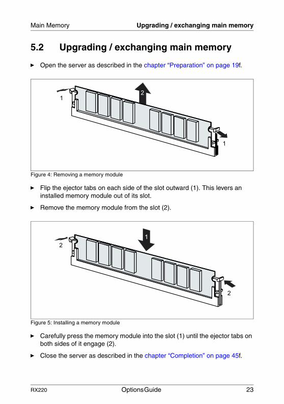
Figure 4: Removing a memory module
Ê Flip the ejector tabs on each side of the slot outward (1). This levers an installed memory module out of its slot.
Ê Remove the memory module from the slot (2).
Figure 5: Installing a memory module
Ê Carefully press the memory module into the slot (1) until the ejector tabs on both sides of it engage (2).
Ê Close the server as described in the chapter “Completion” on page 45f.
�
�
�
�
�
�
RX220 Options Guide 23


6 ProcessorsV CAUTION!
Please observe the safety information in the chapter “Safety Instructions” on page 13ff.
V CAUTION!
Processors are components which are extremely sensitive to electro-static discharge and must be handled with caution. When you take a processor out of its protective wrapper or out of a socket, place it on an insulated, antistatic surface with the smooth side down. Never slide a processor over a surface.
6.1 Installing a second processor
The system board can be upgraded with a second processor.
V CAUTION!
You may only use processors of the same type. The second processor must have the same clock frequency as the first. For dual-processor mode use a suitable multiprocessor operating system.
Ê Open the server as described in the chapter “Preparation” on page 19f.
RX220 Options Guide 25

Installing a second processor Processors
Removing the ventilation duct
Figure 6: Removal of the ventilation duct
Ê Lift off the ventilation duct upwards.
Installing the processor
Figure 7: Opening the socket lever
Ê Release the socket lever by pressing it sideways and lifting it up as far as it will go.
26 Options Guide RX220

Processors Installing a second processor
Figure 8: Installing the processor
Ê Position the new processor over the socket and fit it into the socket by carefully pushing it downwards (1).
V CAUTION!
The processor can only be installed in one direction. Pay attention to the marking on one of the corners for the correct alignment (see figure). To avoid damaging the pins or the processor, do not force the processor into the socket.
Figure 9: Installing the processor
Ê Lock the processor into place in the socket by pushing the socket lever back into its original position (2).
1
2
RX220 Options Guide 27

Installing a second processor Processors
Installing the heat sink
Figure 10: Installing the heat sink
Ê Fasten the heat sink with four screws in diagonally opposite sequence. (The heat sinks are always equipped with the screws).
V CAUTION!
Never install a processor without a heat sink! The processor is likely to overheat, which may cause damage to the processor and the system board.
28 Options Guide RX220

Processors Installing a second processor
Installing the ventilation duct
Figure 11: Installation of the ventilation duct
Ê Reinstall the ventilation duct and press it at the green touchpoints (PUSH) downward.
Ê Close the server as described in the chapter “Completion” on page 45.
RX220 Options Guide 29

Exchanging the processor Processors
6.2 Exchanging the processor
V CAUTION!
You may only use processors of the same type on the system board.
Ê Open the server as described in the chapter “Preparation” on page 19f.
Ê Remove the ventilation duct (see page 26).
Figure 12: Removing the processor heat sink
Ê Remove the four screws of the heat sink in diagonally opposite sequence (see figure).
Ê Turn the heat sink carefully back and forth to loosen it. Then lift it out to remove it.
Ê Remove the residual thermal paste from the underside of the heat sink.
Ê Clean the underside of the heat sink using a lint-free cloth.
30 Options Guide RX220

Processors Exchanging the processor
Figure 13: Removing the old processor
Ê Release the socket lever by pressing it sideways and lifting it up as far as it will go (1).
Ê Lift the installed processor carefully out of its socket (2).
Figure 14: Installing the new processor
Ê Position the new processor above the socket, and press it carefully into the socket (1).
V CAUTION!
The processor can only be installed in one direction. Pay attention to the marking on one of the corners for the correct alignment. To avoid damaging the pins or the processor, do not force the processor into the socket.
Ê Lock the processor into place in the socket by pushing the socket lever back into its original position (2).
2
1
12
RX220 Options Guide 31

Exchanging the processor Processors
Ê Apply a small amount of thermal paste to the top of the new processor.
Ê Spread the paste thinly and evenly.
Ê Fit the heat sink on the processor (see page 28).
Ê Tighten the screws in diagonally opposite sequence (see page 28).
Ê Reinstall the ventilation duct (see page 29).
Ê Close the server as described in the chapter “Completion” on page 45.
32 Options Guide RX220

7 Accessible DriveV CAUTION!
Please observe the safety information in the chapter “Safety Instructions” on page 13ff.
The PRIMERGY RX220 server offers a slot for an accessible drive such as CD-ROM/DVD drive.
The drive can be installed into the top bay. The bay is intended for a 5.25 x 0.5 inch CD-ROM/DVD drive.
7.1 Installing a CD-ROM/DVD drive
You can install a CD-ROM/DVD drive in the top bay. If the bay is empty, a dummy cover will have been fitted.
Removing the dummy cover
Figure 15: Dummy cover
Ê Use a small screwdriver to push the two locks (1) of the dummy from the holes on top of the server.
Ê Pick the dummy cover with a screwdriver to the direction of the arrow, then remove (2).
1
1
2
RX220 Options Guide 33

Installing a CD-ROM/DVD drive Accessible Drive
V CAUTION!
Keep the dummy cover for future use. If you remove the drive without installing a new one, you must reinstall the dummy cover to comply with EMC regulations and to satisfy cooling requirements and fire protection measures.
Installing a CD-ROM/DVD drive
Figure 16: Mounting the drive in its frame
Ê Insert the CD-ROM/DVD drive in its frame and secure it with four screws.
34 Options Guide RX220

Accessible Drive Installing a CD-ROM/DVD drive
Figure 17: Mounting the drive in its bay
Ê Push the CD-ROM/DVD drive into its bay from the front until it engages.
Figure 18: Installing the CD-ROM/DVD drive
2
1
RX220 Options Guide 35

Installing a CD-ROM/DVD drive Accessible Drive
Ê Plug the data cable (1) and the power cable (2) into the CD-ROM/DVD drive.
Ê Close the server as described in the chapter “Completion” on page 45f.
36 Options Guide RX220

8 Controllers in Non-Hot-Plug PCI Slots
V CAUTION!
Please observe the safety information in the chapter “Safety Instructions” on page 13ff.
If you want to replace components which are not hot-pluggable, you must proceed as follows:
Ê Shut down the operating system
Ê Switch off the server, and
Ê Unplug the power plugs.
The system board contains two PCI slots, which can only be used via a riser card because of the height of the server:
– PCI-X slot 1: 64 bit/133 MHz, max. length 315 mm
– PCI Express x8 slot 2: PCI Express 1.0a specifications, max. length 170mm
I Both slots are not hot-pluggable.
RX220 Options Guide 37

Installing controllers Controllers in Non-Hot-Plug PCI Slots
8.1 Installing controllers
Ê Open the server as described in the chapter “Preparation” on page 19f.
Removing the riser card
Figure 19: Removing the riser card
Ê Pull out the riser card holder upwards.
I Please take notice of the green lables on the riser card holder.They marks where the holder should be touched for pulling out or pushing in.
Installing a PCI board
Ê Please read the documentation supplied with the PCI board.
Ê Plug any necessary cables into the PCI board.
Ê Remove the slot cover from the PCI board, if any.
38 Options Guide RX220

Controllers in Non-Hot-Plug PCI Slots Installing controllers
I Keep the slot cover for future use. If you remove the board without installing a new one, you must reinstall the slot cover to comply with EMC regulations (regulations on electromagnetic compatibility) and to satisfy cooling requirements and fire protection measures.
Figure 20: Mounting the board
Ê Plug the board into the PCI slot on the riser card that is suitable for the height of the board.
I Make sure that the slot cover fits into the appropriate recess.
Ê If necessary, plug in the cables on the board and other components.
RX220 Options Guide 39
Installing controllers Controllers in Non-Hot-Plug PCI Slots
Reinstalling the riser card holder
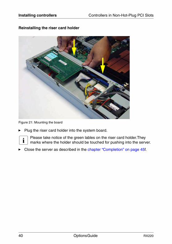
Figure 21: Mounting the board
Ê Plug the riser card holder into the system board.
I Please take notice of the green lables on the riser card holder.They marks where the holder should be touched for pushing into the server.
Ê Close the server as described in the chapter “Completion” on page 45f.
40 Options Guide RX220

9 RemoteView ComponentsV CAUTION!
Please observe the safety information in the chapter “Safety Instructions” on page 13ff.
9.1 Installing the RemoteView Service Board S2 LP
I How to install/remove and configure the RSB S2 LP is described in detail in the manual “RemoteView Service Board S2/S2 LP 1.x, Mounting and Setting Up”.
The RemoteView Service Board S2 LP (RSB S2 LP) is a PCI board including a completely independent system, i.e. it has a separate operating system with a Web server and SNMP agent and can be driven by an external power supply.
The RSB S2 LP should preferably be installed in the low-profile PCI slot, but can also be installed in the full-height slot.
It is connected to the system board via a data cable and a power cable. The RSB S2 LP enables remote diagnostics for system analysis, remote system configuration, and a remote restart if the operating system fails or if a hardware error occurs.
Ê Open the server as described in the chapter “Preparation” on page 19f.
Ê Remove the riser card holder (see page 38).
Ê Plug the supplied power cable into the J302 connector on the RSB S2 LP.
Ê Plug the supplied data cable into the J104 connector on the RSB S2 LP.
Ê Remove the slot cover.
I Keep the slot cover for future use. If you remove the RSB S2 without installing a new one, you must reinstall the slot cover to comply with EMC regulations (regulations on electromagnetic compatibility) and to satisfy cooling requirements and fire protection measures.
Ê Install the RSB S2 LP in the PCI-X slot of the riser card. The procedure is described in the section “Installing controllers” on page 38.
RX220 Options Guide 41

Installing the RemoteView Service Board S2 LP RemoteView Components
Figure 22: Installing the RSB S2 LP
Plug the power cable into the RSB_LB_POW (1) connector of the system board.
I The position of the connectors is described in the “Technical Manual of the System Board D2130” and the System board lable.
Ê Plug the data cable into the IPMB connector (IPMB1) (2) of the system board.
21
42 Options Guide RX220
RemoteView Components Installing the RemoteView Service Board S2 LP
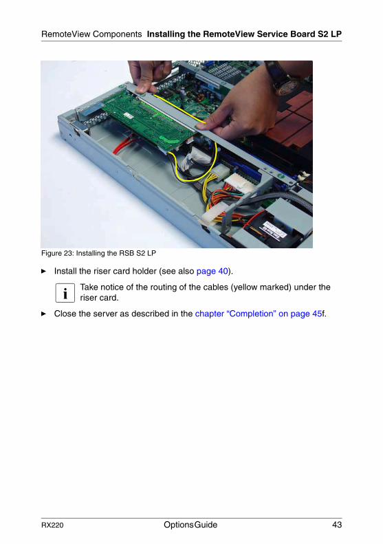
Figure 23: Installing the RSB S2 LP
Ê Install the riser card holder (see also page 40).
I Take notice of the routing of the cables (yellow marked) under the riser card.
Ê Close the server as described in the chapter “Completion” on page 45f.
RX220 Options Guide 43


10 CompletionV CAUTION!
Please observe the safety information in the chapter “Safety Instructions” on page 13ff.
10.1 Closing the server
Figure 24: Installing the cover
Ê Position the cover in such a way that the rear edge protrudes 3-4 cm from the housing.
Ê Push the cover to the front as far as it will go (1).
Ê Attach the cover with the knurled screw (2)at the back of the housing.
Ê Install the server into the telescopic rails of the rack.
I How to install the server in the rack is described in the operating manual.
�
�
��
RX220 Options Guide 45

Closing the server Completion
Figure 25: Installing the server
Ê Press the locking springs (a).
Ê Slide the server into the rack (1) until the telescopic bars click into place.
I After you have inserted the server, you should pull it out again as far as it will go and then push it back in. This ensures that the server runs cleanly on the telescopic rails.
Ê Fasten the server at the front using the two knurled screws (2).
Ê Plug in the power plugs and switch the server on.
a
46 Options Guide RX220
AbbreviationsAC
Alternating Current
ANSIAmerican National Standards Institute
ASR&RAutomatic Server Reconfiguration and Restart
BIOSBasic Input/Output System
BMCBaseboard Management Controller
CCCache Coherency
CDCompact Disk
CD-ROMCompact Disk Read-Only Memory
CHSCylinder Head Sector
CMOSComplementary Metal Oxide Semiconductor
COMCommunication
CPUCentral Processing Unit
DCDirect Current
DIMM
RX220 Options Guide 47

Abbreviations
Dual Inline Memory Module
DIPDual Inline Package
DMADirect Memory Access
DMIDesktop Management Interface
ECCError Checking and Correcting
ECPExtended Capabilities Port
EEPROMElectrically Erasable Programmable Read-Only Memory
EMCElectroMagnetic Compatibility
EMPEmergency Management Port
EPPEnhanced Parallel Port
ESDElectrostatic-Sensitive Devices
FPCFront Panel Controller
FRUField Replaceable Unit
FSBFront Side Bus
GAM
48 Options Guide RX220
Abbreviations
Global Array Manager
GUIGraphical User Interface
HDDHard Disk Drive
HSCHot-Swap Controller
I²CInter-Integrated Circuit
I/OInput/Output
ICMIntelligent Chassis Management
IDIdentification
IDEIntegrated Drive Electronics
IRQInterrupt Request Line
LANLocal Area Network
LBALogical Block Address
LCDLiquid Crystal Display
LUNLogical Unit Number
LVD
RX220 Options Guide 49

Abbreviations
Low-Voltage Differential SCSI
MMFMulti-Mode Fiber
MRLManual-Retention Latch
NMINon-Maskable Interrupt
NVRAMNon-Volatile Random Access Memory
OSOperating System
PCIPeripheral Component Interconnect
PDAPrefailure Detection and Analysis
POSTPower-ON Self-Test
RAIDRedundant Arrays of Independent Disks
RAMRandom Access Memory
ROMRead-Only Memory
RSBRemote Service Board
RTCReal-Time Clock
RTDS
50 Options Guide RX220

Abbreviations
Remote Test and Diagnosis System
SAF-TESCSI Accessed Fault-Tolerance Enclosures
SBESingle-Bit Error
SCASingle-Connector Attachment
SCSISmall Computer System Interface
SDRSensor Data Record
SDRAMSynchronous Dynamic Random Access Memory
SELSystem Event Log
SMISystem Management Interrupt
SSUSystem Setup Utility
SVGASuper Video Graphics Adapter
USBUniversal Serial Bus
VGAVideo Graphics Adapter
ZCRZero Channel RAID
RX220 Options Guide 51


Related publicationsPRIMERGY manuals are available as PDF file on the ServerBooks CD. The ServerBooks CD is part of the ServerStart Bundle delivered with each server system.
The actual version of the necessary manuals can be downloaded free of charge from the Internet. The overview page showing the online documentation available in the Internet can be found via the URL:http://manuals.fujitsu-siemens.com (choose: intel based servers.
[1] Safety
[2] Warranty
[3] 19 inch rack Technical Manual
[4] DataCenter Rack Technical Manual
[5] PRIMECENTER Rack Technical Manual
[6] LocalView User Manual
[7] ServerView Server ManagementUser Manual
[8] ServerView ExtensionServerView Extension for HP OpenView NNM
[9] ServerView/Plus for Tivoli
[10] RemoteView User Manual
[11] RemoteView Service Board S2/S2 LP 1.xMounting and Setting Up User’s Guide
RX220 Options Guide 53
Related publications
[12] PRIMERGY ServerView Suite ServerStart
[13] PRIMERGY RX220 Service Supplement
[14] System Board D2130 Technical Manual
[15] BIOS-Setup Reference Manual
[16] Integrated Mirroring User’s Guide
[17] Global Array Manager Client Software User’s Guide
[18] Global Array Manager Server Software User’s Guide
[19] Ergonomics
[20] Configurator For partners and distributors only:http://extranet.fujitsu-siemens.com/cafe/products/primergy
54 Options Guide RX220

Index
Aaccessible drives 7additional documentation 5Bbatteries 16
CCD-ROM/DVD drive
installation 34upgrade 33
controller 7upgrade 38
coverinstallation 45removal 20
Ddual-processor mode 25dummy cover 33
Eelectrostatic sensitive devices 17ESD 17ESD label 17exchange
main memory 23processor 30
Hheat sink
installation 28
Iinformation material 6installation
CD-ROM/DVD drive 34cover 45RemoteView Service Board S2
LP 41riser card holder 40ventilation duct 29
Llight-emitting diode (LED) 17lithium battery
exchange 16
Mmain memory
exchange 23upgrade 7, 23
meaning of the symbols 9multiprocessor operating system 25
Nnotational conventions 9notes
on handling CDs 16on the laser 17
PPCI board
upgrade 38processor
exchange 30installation 25, 26module 26upgrade 7
RRemoteView 7RemoteView Service Board S2 LP
installation 41introduction 7
removalcover 20riser card holder 38ventilation duct 26
riser card holderinstallation 40removal 38
RX220 Options Guide 55

Index
Ttarget group 5
Uupgrade
CD-ROM/DVD drive 33controller 38main memory 23PCI board 38
Vventilation duct
installation 29
removal 26
56 Options Guide RX220

Comments on PRIMERGY RX220 Serversystem
CommentsSuggestionsCorrections
✁
Submitted by
Fujitsu Siemens Computers GmbHUser Documentation33094 PaderbornGermany
Fax: 0 700 / 372 00001
email: [email protected]://manuals.fujitsu-siemens.com


Comments on PRIMERGY RX220 Serversystem
CommentsSuggestionsCorrections
✁
Submitted by
Fujitsu Siemens Computers GmbHUser Documentation33094 PaderbornGermany
Fax: 0 700 / 372 00001
email: [email protected]://manuals.fujitsu-siemens.com


Information on this document On April 1, 2009, Fujitsu became the sole owner of Fujitsu Siemens Compu-ters. This new subsidiary of Fujitsu has been renamed Fujitsu Technology So-lutions.
This document from the document archive refers to a product version which was released a considerable time ago or which is no longer marketed.
Please note that all company references and copyrights in this document have been legally transferred to Fujitsu Technology Solutions.
Contact and support addresses will now be offered by Fujitsu Technology So-lutions and have the format …@ts.fujitsu.com.
The Internet pages of Fujitsu Technology Solutions are available at http://ts.fujitsu.com/... and the user documentation at http://manuals.ts.fujitsu.com.
Copyright Fujitsu Technology Solutions, 2009
Hinweise zum vorliegenden Dokument Zum 1. April 2009 ist Fujitsu Siemens Computers in den alleinigen Besitz von Fujitsu übergegangen. Diese neue Tochtergesellschaft von Fujitsu trägt seit-dem den Namen Fujitsu Technology Solutions.
Das vorliegende Dokument aus dem Dokumentenarchiv bezieht sich auf eine bereits vor längerer Zeit freigegebene oder nicht mehr im Vertrieb befindliche Produktversion.
Bitte beachten Sie, dass alle Firmenbezüge und Copyrights im vorliegenden Dokument rechtlich auf Fujitsu Technology Solutions übergegangen sind.
Kontakt- und Supportadressen werden nun von Fujitsu Technology Solutions angeboten und haben die Form …@ts.fujitsu.com.
Die Internetseiten von Fujitsu Technology Solutions finden Sie unter http://de.ts.fujitsu.com/..., und unter http://manuals.ts.fujitsu.com finden Sie die Benutzerdokumentation.
Copyright Fujitsu Technology Solutions, 2009


