rx220 group, rx21a group
TRANSCRIPT

APPLICATION NOTE
R01AN1955EJ0100 Rev.1.00 Page 1 of 50 May 07, 2014
RX220 Group, RX21A Group Communication with EEPROM Using the Renesas I2C Bus Module (RIIC)
Introduction This application note describes single-master communication with EEPROM using the RIIC (I²C bus interface) provided by the Renesas RX220 Group and RX21A Group microcontrollers.
Target Devices RX220 Group and RX21A Group
When this application note is used with other microcontrollers, modifications according to the specifications of the microcontroller used and thorough testing and evaluation are required.
Contents
1. Specifications .................................................................................................................................... 2
2. Confirmed Operating Condition ......................................................................................................... 4
3. Reference Application Notes ............................................................................................................. 5
4. Hardware ........................................................................................................................................... 6
5. Operation ........................................................................................................................................... 7
6. Sample Code ................................................................................................................................... 49
7. Usage Notes .................................................................................................................................... 49
8. Reference Documents..................................................................................................................... 50
R01AN1955EJ0100 Rev.1.00
May 07, 2014

RX220 Group, RX21A Group Communication with EEPROM Using the Renesas I2C Bus Module (RIIC)
R01AN1955EJ0100 Rev.1.00 Page 2 of 50 May 07, 2014
1. Specifications This sample program communicates with the EEPROM to write 8 bytes of data and then read the written data back. Between the write and read operations, it uses acknowledge polling to verify that the EEPROM write has completed.
Table 1.1 lists the peripheral functions used and their uses, table 1.2 lists the RIIC settings, table 1.3 lists the EEPROM specifications used with the RX220 Group microcontrollers, and table 1.4 lists the EEPROM specifications used with the RX21A Group microcontrollers. Figure 1.1 shows the circuit diagram for the RX220 and figure 1.2 shows the circuit diagram for the RX21A.
Table 1.1 Peripheral Functions Used and Their Uses
Peripheral function Use RIIC Master transmission, master reception Table 1.2 RIIC Settings
Item Settings Operating frequencies Internal reference clock (IICφ): 20 MHz Master/slave Single master Address format 7-bit address format Transfer speed 400 Kbps Timeout detection • The detection function counts while the SCLn line is low.
• Long mode (16-bit counter (IICφ): about 3.277 ms) Table 1.3 EEPROM Specifications Used with the RX220
Item Settings Catalog number R1EX24016ASAS0A Capacity 16K (2-kword × 8-bit) Slave address Slave address: 1010xxxx
Bit 0 is the R/W bit and bits 1 to 3 indicate the page in EEPROM. See the specifications of the EEPROM for further details.
Write protection Always cleared • WP pin level: low level
Table 1.4 EEPROM Specifications Used with the RX21A
Item Settings Catalog number R1EX24512ASAS0A Capacity 512K (64-kword × 8-bit) Slave address Slave address: 1010xxxx
Bit 0 is the R/W bit and bits 1 and 2 indicate the page in EEPROM. See the specifications of the EEPROM for further details.
Write protection Always cleared • WP pin level: low level

RX220 Group, RX21A Group Communication with EEPROM Using the Renesas I2C Bus Module (RIIC)
R01AN1955EJ0100 Rev.1.00 Page 3 of 50 May 07, 2014
P12/SCL
Renesas Starter Kit for RX220
RX220 Group(R5F52206BDFP)
P13/SDA
EEPROM(R1EX24016ASAS0A)
SCL
SDA WP
Board_VCC
20 MHz4.
7K
4.7K
GROUND
Slave address: 1010xxxx(Bit 0 is the R/W bit and bits 1 to 3 indicate the page in EEPROM.)
100
K
Figure 1.1 RX220 Circuit Diagram
P12/SCL0
HSB Series microcontroller board manufactured
by Hokuto Denshi Co., Ltd.
RX21A Group(R5F521A8BDFP)
P13/SDA0
EEPROM(R1EX24512ASAS0A)
SCL
SDA WP
Board_VCC
20 MHz
4.7
K
4.7
K
GROUND
Slave address: 1010xxxx(Bit 0 is the R/W bit and bits 1 and 2
indicate the page in EEPROM.)
EEPROM evaluation board
P21/SCL1
P20/SDA1
Figure 1.2 RX21A Circuit Diagram

RX220 Group, RX21A Group Communication with EEPROM Using the Renesas I2C Bus Module (RIIC)
R01AN1955EJ0100 Rev.1.00 Page 4 of 50 May 07, 2014
2. Confirmed Operating Condition The sample code accompanying this application note has been run and confirmed under the conditions below.
Table 2.1 Conditions Under which Operation has been Confirmed - RX220
Item Description MCU used R5F52206BDFP (RX220 Group) Operating frequency Main clock: 20.0 MHz
System clock (ICLK): 20 MHz (main clock divided by 1) Peripheral module clock B (PCLKB): 20 MHz (main clock divided by 1) External bus clock (BCLK): 20 MHz (main clock divided by 1)
Operating voltage 5.0 V: Supplied from the E1 emulator Integrated development environment
Renesas Electronics Corporation High-performance Embedded Workshop Version 4.09.01.007
C compiler Renesas Electronics Corporation C/C++ Compiler Package for RX Family V.1.02 Release 01 Compiler option -cpu=rx200 -output=obj="$(CONFIGDIR)\$(FILELEAF).obj" -debug –nologo (The integrated development environment default settings are used.)
iodefine.h version Version 1.0A Endian order Little endian Operating mode Single-chip mode Processor mode Supervisor mode Sample code version Version 1.00 Board used Renesas Starter Kit for RX220 (Product number: R0K505220S000BE)
RX220 Group, RX21A Group Communication with EEPROM Using the Renesas I2C Bus Module (RIIC)
R01AN1955EJ0100 Rev.1.00 Page 5 of 50 May 07, 2014
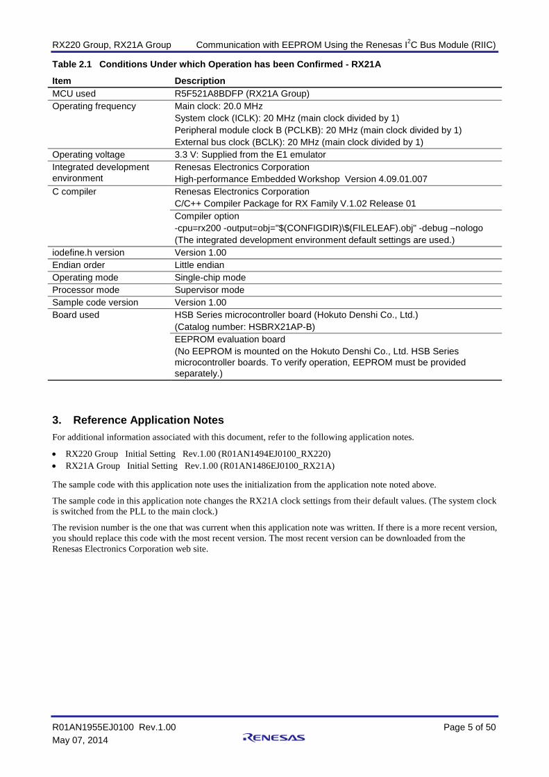
Table 2.1 Conditions Under which Operation has been Confirmed - RX21A
Item Description MCU used R5F521A8BDFP (RX21A Group) Operating frequency Main clock: 20.0 MHz
System clock (ICLK): 20 MHz (main clock divided by 1) Peripheral module clock B (PCLKB): 20 MHz (main clock divided by 1) External bus clock (BCLK): 20 MHz (main clock divided by 1)
Operating voltage 3.3 V: Supplied from the E1 emulator Integrated development environment
Renesas Electronics Corporation High-performance Embedded Workshop Version 4.09.01.007
C compiler Renesas Electronics Corporation C/C++ Compiler Package for RX Family V.1.02 Release 01 Compiler option -cpu=rx200 -output=obj="$(CONFIGDIR)\$(FILELEAF).obj" -debug –nologo (The integrated development environment default settings are used.)
iodefine.h version Version 1.00 Endian order Little endian Operating mode Single-chip mode Processor mode Supervisor mode Sample code version Version 1.00 Board used HSB Series microcontroller board (Hokuto Denshi Co., Ltd.)
(Catalog number: HSBRX21AP-B) EEPROM evaluation board (No EEPROM is mounted on the Hokuto Denshi Co., Ltd. HSB Series microcontroller boards. To verify operation, EEPROM must be provided separately.)
3. Reference Application Notes For additional information associated with this document, refer to the following application notes.
• RX220 Group Initial Setting Rev.1.00 (R01AN1494EJ0100_RX220) • RX21A Group Initial Setting Rev.1.00 (R01AN1486EJ0100_RX21A) The sample code with this application note uses the initialization from the application note noted above.
The sample code in this application note changes the RX21A clock settings from their default values. (The system clock is switched from the PLL to the main clock.)
The revision number is the one that was current when this application note was written. If there is a more recent version, you should replace this code with the most recent version. The most recent version can be downloaded from the Renesas Electronics Corporation web site.

RX220 Group, RX21A Group Communication with EEPROM Using the Renesas I2C Bus Module (RIIC)
R01AN1955EJ0100 Rev.1.00 Page 6 of 50 May 07, 2014
4. Hardware
4.1 Pins Tables 4.1 and 4.2 list the pins used and their functions for the RX220 and RX21A, respectively.
Table 4.1 RX220 Pins and Functions
Pin Name I/O Function P12/SCL Input/output RIIC0 serial clock input and output P13/SDA Input/output RIIC0 serial data input and output
Table 4.1 RX21A Pins and Functions
Pin Name I/O Function P12/SCL0 Input/output RIIC0 serial clock input and output P13/SDA0 Input/output RIIC0 serial data input and output P21/SCL1 Input/output RIIC1 serial clock input and output P20/SDA1 Input/output RIIC1 serial data input and output

RX220 Group, RX21A Group Communication with EEPROM Using the Renesas I2C Bus Module (RIIC)
R01AN1955EJ0100 Rev.1.00 Page 7 of 50 May 07, 2014
5. Operation
5.1 Writing to the EEPROM This sample program uses master transmission for writing to an external EEPROM device. The RIIC module issues a start condition (S) and then sends the EEPROM’s slave address. Since the eighth bit at this time is the R/W bit, a 0 must be sent at write time (master transmission). After that, the memory address is sent as two 8-bit bytes, and then the data to be written is sent to the EEPROM in order. The 2-byte memory address transmitted at this time indicates the address for the write operation in EEPROM. After the transmission of all the data has completed, the RIIC module issues a stop condition (P) and releases the bus. Note that the write address in memory used in this application note is 0000h.
Figure 5.1 shows an example of the signals used when writing the EEPROM.
S 1 2 3 4 5 6 7 8 1 2 3 4 5 6 7 8 1 2 3 4 5 6 7 8 1 2 3 4 5 6 7 8 P
SCLn
SDAn
Slave address(A6h)
1st Memory address
2nd Memory address
Write DataStart
1 2 7 8
Write Data(n) Stop
ACK
ACK
ACK
ACK
ACK
ACK
ACK
ACK
ACK
ACK
Figure 5.1 Signals when Writing to EEPROM
5.2 Reading from EEPROM A compound format consisting of master transmission and master reception is used for reading data from EEPROM. First, the RIIC module issues a start condition (S) and then it transmits the EEPROM slave address and then a two byte (2 × 8 bits) memory address. At this time, the RIIC module sends 0 as the R/W bit in the EEPROM slave address transmission (master transmission). After that, it issues a restart condition (Sr) and sends the EEPROM slave address again. At this time, it transmits 1 as the R/W bit in the transmission to the EEPROM (master reception). After the EEPROM slave address has been sent, the data is read out from the EEPROM by the generation of the next clock cycle. During the read operation, the RIIC module transmits an ACK each time it receives a single byte. For the last data, however, it returns a NACK. After that, it generates a stop condition (P). Note that the memory address read by this sample program is 0000h.
Figure 5.2 shows an example of the signals used when reading the EEPROM.
S 1 2 3 4 5 6 7 8 1 2 3 4 5 6 7 8 1 2 3 4 5 6 7 8 1 2 3 4 5 6 7 8
SCLn
SDAn
Slave address(A6h)
1st Memory address
2nd Memory address
Read Data (n)Start Stop
Sr
ReStart
1 2 3 4 5 6 7 8
Slave address(A7h)
P
Master transmission Master reception
ACK
ACK
ACK
ACK
ACK
ACK
ACK
ACK
ACK
NACK
Figure 5.2 Signals when Reading from EEPROM
RX220 Group, RX21A Group Communication with EEPROM Using the Renesas I2C Bus Module (RIIC)
R01AN1955EJ0100 Rev.1.00 Page 8 of 50 May 07, 2014
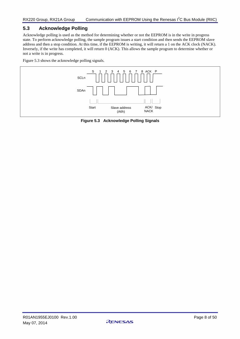
5.3 Acknowledge Polling Acknowledge polling is used as the method for determining whether or not the EEPROM is in the write in progress state. To perform acknowledge polling, the sample program issues a start condition and then sends the EEPROM slave address and then a stop condition. At this time, if the EEPROM is writing, it will return a 1 on the ACK clock (NACK). Inversely, if the write has completed, it will return 0 (ACK). This allows the sample program to determine whether or not a write is in progress.
Figure 5.3 shows the acknowledge polling signals.
S 1 2 3 4 5 6 7 8 ACK
SCLn
SDAn
Slave address(A6h)
ACK/NACK
Start Stop
P
Figure 5.3 Acknowledge Polling Signals

RX220 Group, RX21A Group Communication with EEPROM Using the Renesas I2C Bus Module (RIIC)
R01AN1955EJ0100 Rev.1.00 Page 9 of 50 May 07, 2014
5.4 File Structure Table 5.1 lists the files in the sample code. Note that this list does not include files generated automatically by the integrated development environment.
Table 5.1 Sample Code Files
Target Device File Name Overview Remarks Common main.c Main processing
iic_eeprom.c Single master transmission and reception iic_eeprom.h Header file for single master transmission
and reception
iic_eeprom_cfg.h Configuration header file for single master transmission and reception
RX220 r_init_stop_module.c Functions to stop peripheral functions operating after a reset
r_init_stop_module.h Header file for r_init_stop_module.c r_init_non_existent_port.c Initialization of nonexistent ports r_init_non_existent_port.h Header file for r_init_non_existent_port.c r_init_clock.c Clock initialization r_init_clock.h Header file for r_init_clock.c
RX21A r_init_stop_module.c Functions to stop peripheral functions operating after a reset
r_init_stop_module.h Header file for r_init_stop_module.c r_init_non_existent_port.c Initialization of nonexistent ports r_init_non_existent_port.h Header file for r_init_non_existent_port.c r_init_clock.c Clock initialization r_init_clock.h Header file for r_init_clock.c
5.5 Option Settings Memory Table 5.2 lists the states of the option settings memory used by the sample code. These should be set to values appropriate for the actual user system as needed.
Table 5.2 Sample Code Option Settings Memory
Symbol Address Setting Value Contents OFS0 FFFF FF8Fh to FFFF FF8Ch FFFF FFFFh Stops IWDT after a reset
Stops WDT after a reset OFS1 FFFF FF8Bh to FFFF FF88h FFFF FFFFh Disables voltage monitoring resets after a reset
Disables HOCOC oscillation after a reset MDES FFFF FF83h to FFFF FF80h FFFF FFFFh Little endian
RX220 Group, RX21A Group Communication with EEPROM Using the Renesas I2C Bus Module (RIIC)
R01AN1955EJ0100 Rev.1.00 Page 10 of 50 May 07, 2014
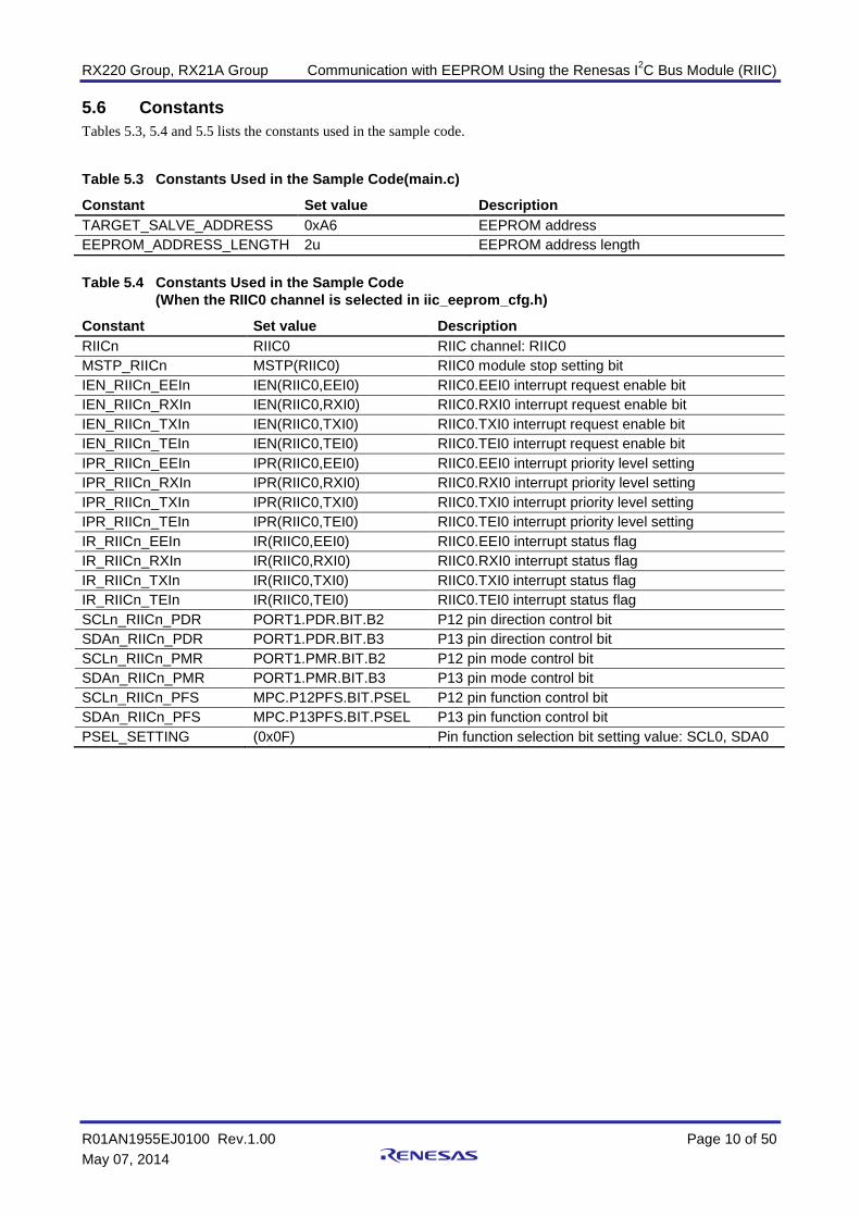
5.6 Constants Tables 5.3, 5.4 and 5.5 lists the constants used in the sample code.
Table 5.3 Constants Used in the Sample Code(main.c)
Constant Set value Description TARGET_SALVE_ADDRESS 0xA6 EEPROM address EEPROM_ADDRESS_LENGTH 2u EEPROM address length Table 5.4 Constants Used in the Sample Code
(When the RIIC0 channel is selected in iic_eeprom_cfg.h)
Constant Set value Description RIICn RIIC0 RIIC channel: RIIC0 MSTP_RIICn MSTP(RIIC0) RIIC0 module stop setting bit IEN_RIICn_EEIn IEN(RIIC0,EEI0) RIIC0.EEI0 interrupt request enable bit IEN_RIICn_RXIn IEN(RIIC0,RXI0) RIIC0.RXI0 interrupt request enable bit IEN_RIICn_TXIn IEN(RIIC0,TXI0) RIIC0.TXI0 interrupt request enable bit IEN_RIICn_TEIn IEN(RIIC0,TEI0) RIIC0.TEI0 interrupt request enable bit IPR_RIICn_EEIn IPR(RIIC0,EEI0) RIIC0.EEI0 interrupt priority level setting IPR_RIICn_RXIn IPR(RIIC0,RXI0) RIIC0.RXI0 interrupt priority level setting IPR_RIICn_TXIn IPR(RIIC0,TXI0) RIIC0.TXI0 interrupt priority level setting IPR_RIICn_TEIn IPR(RIIC0,TEI0) RIIC0.TEI0 interrupt priority level setting IR_RIICn_EEIn IR(RIIC0,EEI0) RIIC0.EEI0 interrupt status flag IR_RIICn_RXIn IR(RIIC0,RXI0) RIIC0.RXI0 interrupt status flag IR_RIICn_TXIn IR(RIIC0,TXI0) RIIC0.TXI0 interrupt status flag IR_RIICn_TEIn IR(RIIC0,TEI0) RIIC0.TEI0 interrupt status flag SCLn_RIICn_PDR PORT1.PDR.BIT.B2 P12 pin direction control bit SDAn_RIICn_PDR PORT1.PDR.BIT.B3 P13 pin direction control bit SCLn_RIICn_PMR PORT1.PMR.BIT.B2 P12 pin mode control bit SDAn_RIICn_PMR PORT1.PMR.BIT.B3 P13 pin mode control bit SCLn_RIICn_PFS MPC.P12PFS.BIT.PSEL P12 pin function control bit SDAn_RIICn_PFS MPC.P13PFS.BIT.PSEL P13 pin function control bit PSEL_SETTING (0x0F) Pin function selection bit setting value: SCL0, SDA0

RX220 Group, RX21A Group Communication with EEPROM Using the Renesas I2C Bus Module (RIIC)
R01AN1955EJ0100 Rev.1.00 Page 11 of 50 May 07, 2014
Table 5.5 Constants Used in the Sample Code (When the RIIC1 channel is selected in iic_eeprom_cfg.h)
Constant Set value Description RIICn RIIC1 RIIC channel: RIIC1 MSTP_RIICn MSTP(RIIC1) RIIC1 module stop setting bit IEN_RIICn_EEIn IEN(RIIC1,EEI1) RIIC1.EEI1 interrupt request enable bit IEN_RIICn_RXIn IEN(RIIC1,RXI1) RIIC1.RXI1 interrupt request enable bit IEN_RIICn_TXIn IEN(RIIC1,TXI1) RIIC1.TXI1 interrupt request enable bit IEN_RIICn_TEIn IEN(RIIC1,TEI1) RIIC1.TEI1 interrupt request enable bit IPR_RIICn_EEIn IPR(RIIC1,EEI1) RIIC1.EEI1 interrupt priority level setting IPR_RIICn_RXIn IPR(RIIC1,RXI1) RIIC1.RXI1 interrupt priority level setting IPR_RIICn_TXIn IPR(RIIC1,TXI1) RIIC1.TXI1 interrupt priority level setting IPR_RIICn_TEIn IPR(RIIC1,TEI1) RIIC1.TEI1 interrupt priority level setting IR_RIICn_EEIn IR(RIIC1,EEI1) RIIC1.EEI1 interrupt status flag IR_RIICn_RXIn IR(RIIC1,RXI1) RIIC1.RXI1 interrupt status flag IR_RIICn_TXIn IR(RIIC1,TXI1) RIIC1.TXI1 interrupt status flag IR_RIICn_TEIn IR(RIIC1,TEI1) RIIC1.TEI1 interrupt status flag SCLn_RIICn_PDR PORT2.PDR.BIT.B1 P21 pin direction control bit SDAn_RIICn_PDR PORT2.PDR.BIT.B0 P20 pin direction control bit SCLn_RIICn_PMR PORT2.PMR.BIT.B1 P21 pin mode control bit SDAn_RIICn_PMR PORT2.PMR.BIT.B0 P20 pin mode control bit SCLn_RIICn_PFS MPC.P21PFS.BIT.PSEL P21 pin function control bit SDAn_RIICn_PFS MPC.P20PFS.BIT.PSEL P20 pin function control bit PSEL_SETTING (0x0F) Pin function selection bit setting value: SCL1, SDA1

RX220 Group, RX21A Group Communication with EEPROM Using the Renesas I2C Bus Module (RIIC)
R01AN1955EJ0100 Rev.1.00 Page 12 of 50 May 07, 2014
5.7 Structures and Unions Figure 5.4 shows the structure used as an argument to the IIC_EeWrite() and IIC_RandomRead() functions. Table 5.6 lists the members of the iic_api_t structure.
struct str_iic_api_t{
uint8_t SlvAdr; /* Slave Address, Don't set bit0. It's a Read/Write bit */uint16_t PreCnt; /* Number of Predata */uint8_t *pPreData; /* Pointer for PreData (Memory Addr of EEPROM) */uint32_t RWCnt; /* Number of Data */uint8_t *pRWData; /* Pointer for Data buffer */
};typedef struct str_iic_api_t iic_api_t;
Figure 5 Structure Uses as an Argument to IIC_EepWrite() and IIC_RandomRead()
Table 6 Members of the Structure IIC_API_T
Structure Member Range of Values Description SlvAdr 00h to FEh Slave address
Since the low-order bit is the R/W bit, it should always beset to 0. PreCnt 00h to FFh Memory address counter
This is always set to 2 in this sample program. *pPreData Memory address storage buffer pointer
On write: The address in EEPROM to write data to (write destination)
On read: The address in EEPROM to read data from (write source)
RWCnt 0000 0000h to FFFF FFFFh
Data counter On write: Number of data items to write to EEPROM On read: Number of data items to read from EEPROM
*pRWData Data storage buffer pointer On write: Storage source for data to write to EEPROM. On read: Storage destination for data read from EEPROM.

RX220 Group, RX21A Group Communication with EEPROM Using the Renesas I2C Bus Module (RIIC)
R01AN1955EJ0100 Rev.1.00 Page 13 of 50 May 07, 2014
5.8 Variables Table 5.7 lists the static Variables.
Table 5.7 Static Variables
Type Variable Name Contents Function Used static uint8_t
trm_eeprom_adr[EEPROM_ADDRESS_LENGTH]
EEPROM slave address storage buffer (for write)
SampleEepromWrite
static unit8_t
rcv_eeprom_adr[EEPROM_ ADDRESS_LENGTH]
EEPROM slave address storage buffer (for read)
SampleEepromRead
static uint8_t
trm_buff[256] Transmit data buffer SampleEepromWrite
static uint8_t
rcv_buff[256] Receive data buffer SampleEepromRead
static iic_api_t
iic_buff_prm[2] Structure used as the argument to the functions IIC_EepWrite() and IIC_RandomRead()
SampleEepromWrite SampleEepromRead
static iic_api_t
iic_buff Structure used as the argument to the functions IIC_EepWrite() and IIC_RandomRead() (Used by both IIC_EepWrite() and IIC_RandomRead())
IIC_EeWrite IIC_RandomRead iic_eei_int_sp iic_eei_int_st iic_rxi_int_eeread iic_txi_int_eewrite iic_txi_int_eeread
static enum riic_internal_mode_t
iic_mode Internal mode IIC_Create IIC_EeWrite IIC_RandomRead iic_eei_int_sp IIC_RXI_interrupt IIC_TXI_interrupt IIC_TEI_interrupt
static enum riic_status_t
iic_status IIC status IIC_Create IIC_EeWrite IIC_RandomRead IIC_GetStatus iic_eei_int_sp iic_eei_int_nack
static unit32_t
iic_trm_cnt Internal IIC transmit counter IIC_Create IIC_EeWrite IIC_RandomRead iic_eei_int_sp iic_txi_int_eewrite iic_txi_int_eeread
static unit32_t
iic_rcv_cnt Internal IIC receive counter IIC_Create IIC_RandomRead iic_eei_int_sp iic_rxi_int_eeread

RX220 Group, RX21A Group Communication with EEPROM Using the Renesas I2C Bus Module (RIIC)
R01AN1955EJ0100 Rev.1.00 Page 14 of 50 May 07, 2014
5.9 Enumerations The IIC status, the IIC bus status, the internal mode, and the return value from the functions IIC_EepWrite() and IIC_RandomRead() are all declared as enumerations. The IIC status values are listed in table 5.8 and their state transition diagram are shown in figure 5.5. Also, table 5.9 lists the IIC bus status values, table 5.10 lists the internal modes, and table 5.11 lists the return values of the functions IIC_EepWrite() and IIC_RandomRead().
The IIC status is stored at the address given by its first argument when the function IIC_GetStatus() is called. The
internal mode is only used in the IIC-related functions in this sample program.
Table 5.8 IIC Status Values (enum RiicStatus_t)
Defined Name Description RIIC_STATUS_IDLE The idle state
The status transitions to this state after initialization in the function IIC_Create(). The status also transitions to this state after either an EEPROM write or an EEPROM read completes normally (after a stop condition is detected).
RIIC_STATUS_ON_COMMUNICATION Communication in progress The status transitions to this state when communication is initiated by either IIC_EepWrite() or IIC_RandomRead().
RIIC_STATUS_NACK NACK received The status transitions to this state when a NACK is received.
RIIC_STATUS_FAILED Communication failure The status transitions to this state when a stop condition is detected before either an EEPROM write or an EEPROM read completes. In this sample program, since a stop condition is generated on either a timeout or an arbitration lost, the status will transition to this state on either of those events as well.
Idle state Communicationin progress
NACKreceived
Communicationfailure
InitializationNACK received
Normal completionof communication
Communication start
Communication start
Stop conditionabnormality detected
After reset iscleared
Initialization: IIC_Create()Start of communication: Either IIC_EepWrite() or IIC_RandomRead()
Start ofcommunication
Figure 5.5 IIC Status State Transition Diagram

RX220 Group, RX21A Group Communication with EEPROM Using the Renesas I2C Bus Module (RIIC)
R01AN1955EJ0100 Rev.1.00 Page 15 of 50 May 07, 2014
Table 5.9 IIC Bus Status (enum riic_bus_status_t)
Defined Name Description RIIC_BUS_STATUS_FREE IIC bus busy RIIC_BUS_STATUS_BBSY IIC bus free Table 5.10 Internal Modes (enum riic_internal_mode_t)
Defined Name Description IIC_MODE_IDLE Idle mode
The internal mode transitions to idle mode on initialization by IIC_Create() or when a stop condition is detected.
IIC_MODE_EE_READ EEPROM read mode The internal mode transitions to this mode at the start of communication due to IIC_RandomRead().
IIC_MODE_EE_WRITE EEPROM write mode The internal mode transitions to this mode at the start of communication due to IIC_EeWrite().
Table 5.11 IIC_EepWrite() and IIC_RandomRead() Return Value (enum riic_ee_fnc_t)
Defined Name Description RIIC_OK This value is returned when communication starts up normally. RIIC_BUS_BUSY This value is returned when the I2C bus is busy. RIIC_MODE_ERROR This value is returned when the RIIC module has a communication
operation in progress. RIIC_PRM_ERROR This value is returned when an illegal argument value is passed.
(Only the function IIC_RandomRead() uses this value.)

RX220 Group, RX21A Group Communication with EEPROM Using the Renesas I2C Bus Module (RIIC)
R01AN1955EJ0100 Rev.1.00 Page 16 of 50 May 07, 2014
5.10 Functions Table 5.12 lists the Functions.
Table 5.12 Function(s)
Function Description main Main processing R_INIT_StopModule Functions to stop peripheral functions operating after a reset R_INIT_NonExistentPort Initialization of nonexistent ports R_INIT_Clock Clock initialization port_init Port initialization peripheral_init Peripheral initialization CpuIntCreate CPU interrupt setting SampleEepromWrite EEPROM write processing example SampleEepromRead EEPROM read processing example IICAckPolling Acknowledge Polling IIC_Create IIC processing setup IIC_Destroy IIC termination processing IIC_EeWrite EEPROM write start processing IIC_RandomRead EEPROM read start processing IIC_GetStatus IIC status check IIC_EEI_interrupt Communication error or event interrupt iic_eei_int_timeout Timeout detection interrupt iic_eei_int_al Arbitration lost detected interrupt iic_eei_int_sp Stop condition detected interrupt iic_eei_int_st Start condition detected interrupt iic_eei_int_nack NACK detected interrupt IIC_RXI_interrupt Receive data full interrupt iic_rxi_int_eeread EEPROM read processing (master reception section) IIC_TXI_interrupt Transmit data empty interrupt iic_txi_int_eewrite EEPROM write processing iic_txi_int_eeread EEPROM read processing (master transmission section) IIC_TEI_interrupt Transmission complete interrupt iic_tei_int_eewrite Transmission end processing used after an EEPROM write iic_tei_int_eeread Transmission end processing used after an EEPROM read iic_gen_clk_sp Stop condition generation used when an error occurs iic_error Error handling Excep_RIICn_EEIn RIICn.EEIn interrupt handler Excep_RIICn_RXIn RIICn.RXIn interrupt handler Excep_RIICn_TXIn RIICn.TXIn interrupt handler Excep_RIICn_TEIn RIICn.TEIn interrupt handler

RX220 Group, RX21A Group Communication with EEPROM Using the Renesas I2C Bus Module (RIIC)
R01AN1955EJ0100 Rev.1.00 Page 17 of 50 May 07, 2014
5.11 Function Specifications The following tables lists the sample code function specifications.
main Overview Main processing Header None Declaration void main(void) Description This function performs initialization, port initialization, and peripheral function
initialization. After that it calls the functions that perform sample EEPROM write processing, acknowledge polling, EEPROM read processing, and IIC processing termination.
Arguments None Return values None
R_INIT_StopModule Overview Functions to stop peripheral functions operating after a reset Header r_init_stop_module.h Declaration void R_INIT_StopModule(void) Description Performs the settings that transition to module stop state. Arguments None Return values None Remarks Transitioning to the module stop state is not performed in the sample code. See the
two application notes RX220 Group Microcontroller initialization Rev.1.00 and RX21A Group Microcontroller Initialization Rev.1.00 for details on this function.
R_INIT_NonExistentPort Overview Initialization of nonexistent ports Header r_init_non_existent_port.h Declaration void R_INIT_NonExistentPort(void) Description Initializes the port direction registers for port pins that do not exist in products
provided in packages with less than 100 pins. Arguments None Return values None Remarks He sample code is set up to operate using 100-pin versions of the microcontrollers
(PIN_SIZE = 100). After this function is called, applications should the port direction control bit to 1 and the port output data storage bit to 0 for ports that do not exist if they will write in byte units to PDR and PODR registers that include ports that do not exist. See the two application notes RX220 Group Microcontroller initialization Rev.1.00 and RX21A Group Microcontroller Initialization Rev.1.00 for details on this function.
RX220 Group, RX21A Group Communication with EEPROM Using the Renesas I2C Bus Module (RIIC)
R01AN1955EJ0100 Rev.1.00 Page 18 of 50 May 07, 2014
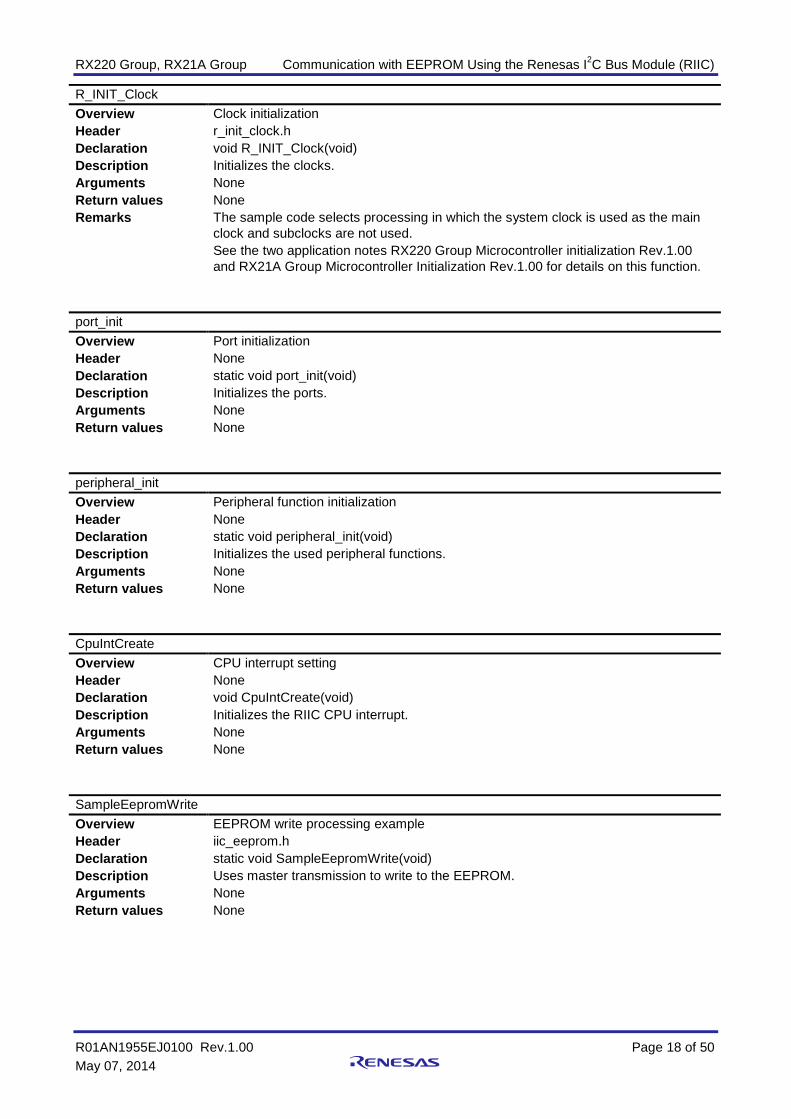
R_INIT_Clock Overview Clock initialization Header r_init_clock.h Declaration void R_INIT_Clock(void) Description Initializes the clocks. Arguments None Return values None Remarks The sample code selects processing in which the system clock is used as the main
clock and subclocks are not used. See the two application notes RX220 Group Microcontroller initialization Rev.1.00 and RX21A Group Microcontroller Initialization Rev.1.00 for details on this function.
port_init Overview Port initialization Header None Declaration static void port_init(void) Description Initializes the ports. Arguments None Return values None
peripheral_init Overview Peripheral function initialization Header None Declaration static void peripheral_init(void) Description Initializes the used peripheral functions. Arguments None Return values None
CpuIntCreate Overview CPU interrupt setting Header None Declaration void CpuIntCreate(void) Description Initializes the RIIC CPU interrupt. Arguments None Return values None
SampleEepromWrite Overview EEPROM write processing example Header iic_eeprom.h Declaration static void SampleEepromWrite(void) Description Uses master transmission to write to the EEPROM. Arguments None Return values None
RX220 Group, RX21A Group Communication with EEPROM Using the Renesas I2C Bus Module (RIIC)
R01AN1955EJ0100 Rev.1.00 Page 19 of 50 May 07, 2014
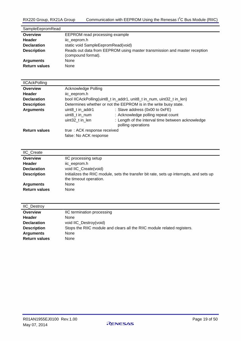
SampleEepromRead Overview EEPROM read processing example Header iic_eeprom.h Declaration static void SampleEepromRead(void) Description Reads out data from EEPROM using master transmission and master reception
(compound format). Arguments None Return values None
IICAckPolling Overview Acknowledge Polling Header iic_eeprom.h Declaration bool IICAckPolling(uint8_t in_addr1, unit8_t in_num, uint32_t in_len) Description Determines whether or not the EEPROM is in the write busy state. Arguments uint8_t in_addr1
uint8_t in_num uint32_t in_len
: Slave address (0x00 to 0xFE) : Acknowledge polling repeat count : Length of the interval time between acknowledge
polling operations Return values true : ACK response received
false : No ACK response
IIC_Create Overview IIC processing setup Header iic_eeprom.h Declaration void IIC_Create(void) Description Initializes the RIIC module, sets the transfer bit rate, sets up interrupts, and sets up
the timeout operation. Arguments None Return values None
IIC_Destroy Overview IIC termination processing Header None Declaration void IIC_Destroy(void) Description Stops the RIIC module and clears all the RIIC module related registers. Arguments None Return values None

RX220 Group, RX21A Group Communication with EEPROM Using the Renesas I2C Bus Module (RIIC)
R01AN1955EJ0100 Rev.1.00 Page 20 of 50 May 07, 2014
IIC_EeWrite Overview EEPROM write start processing Header iic_eeprom.h Declaration enum riic_ee_fnc_t IIC_EeWrite(iic_api_t data1) Description Uses master transmission to write to the EEPROM. If the I2C bus is busy or if the
RIIC module is in the communication in progress state, it does not start master transmission.
Arguments iic_api_t data1 : Slave address Memory address counter Memory address storage buffer pointer Data counter Data storage buffer pointer
Return values RIIC_OK : If communication starts up normally RIIC_BUS_BUSY : If the I2C bus is busy RIIC_MODE_ERROR: If the RIIC module is communicating
IIC_RandomRead Overview EEPROM read start processing Header iic_eeprom.h Declaration enum riic_ee_fnc_t IIC_RandomRead(iic_api_t data1) Description Reads data from EEPROM using master transmission and master reception
(compound format). If the I2C bus is busy or the RIIC is already communicating, it does not start a master transmission.
Arguments iic_api_t data1 : Slave address Memory address counter Memory address storage buffer pointer Data counter Data storage buffer pointer
Return values RIIC_OK : If communication starts up normally RIIC_BUS_BUSY : If the I2C bus is busy RIIC_MODE_ERROR: If the RIIC module is communicating RIIC_PRM_ERROR : If the argument value is illegal
IIC_GetStatus Overview IIC status check Header iic_eeprom.h Declaration void IIC_GetStatus(enum riic_status_t *data1,enum riic_bus_status_t *data2) Description This function stores the IIC status in the area indicated by the first argument. It also
stores the IIC bus state in the area indicated by the second argument. Arguments Enum riic_status_t *data1
Enum riic_bus_status *data2 : IIC status : IIC bus status
Return values None
IIC_EEI_interrupt Overview Communication error or event interrupt Header None Declaration void IIC_EEI_interrupt(void) Description Calls the handler for the detected interrupt request. Arguments None Return values None
RX220 Group, RX21A Group Communication with EEPROM Using the Renesas I2C Bus Module (RIIC)
R01AN1955EJ0100 Rev.1.00 Page 21 of 50 May 07, 2014
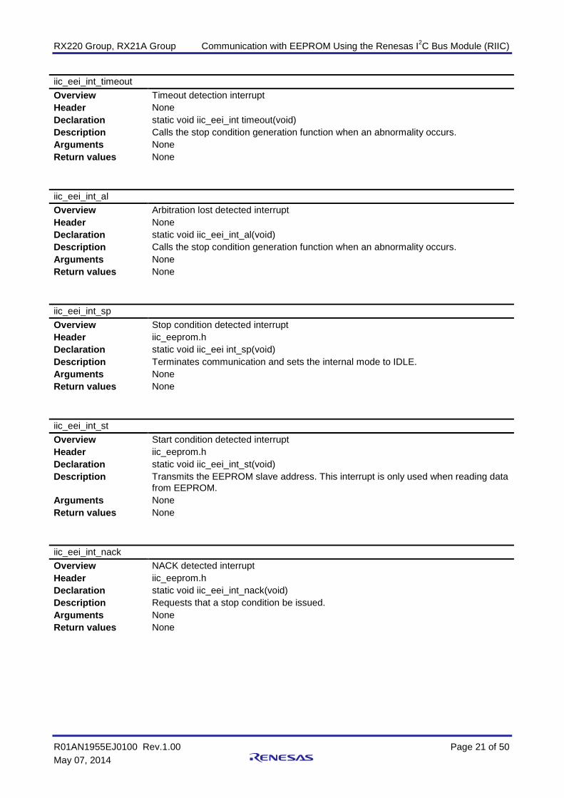
iic_eei_int_timeout Overview Timeout detection interrupt Header None Declaration static void iic_eei_int timeout(void) Description Calls the stop condition generation function when an abnormality occurs. Arguments None Return values None
iic_eei_int_al Overview Arbitration lost detected interrupt Header None Declaration static void iic_eei_int_al(void) Description Calls the stop condition generation function when an abnormality occurs. Arguments None Return values None
iic_eei_int_sp Overview Stop condition detected interrupt Header iic_eeprom.h Declaration static void iic_eei int_sp(void) Description Terminates communication and sets the internal mode to IDLE. Arguments None Return values None
iic_eei_int_st Overview Start condition detected interrupt Header iic_eeprom.h Declaration static void iic_eei_int_st(void) Description Transmits the EEPROM slave address. This interrupt is only used when reading data
from EEPROM. Arguments None Return values None
iic_eei_int_nack Overview NACK detected interrupt Header iic_eeprom.h Declaration static void iic_eei_int_nack(void) Description Requests that a stop condition be issued. Arguments None Return values None

RX220 Group, RX21A Group Communication with EEPROM Using the Renesas I2C Bus Module (RIIC)
R01AN1955EJ0100 Rev.1.00 Page 22 of 50 May 07, 2014
IIC_RXI_interrupt Overview Receive data full interrupt Header iic_eeprom.h Declaration void IIC_RXI_interrupt(void) Description Checks the internal mode and calls a handler. Arguments None Return values None
iic_rxi_int_eeread Overview EEPROM read processing (master reception section) Header iic_eeprom.h Declaration static void iic_rxi_int_eeread(void) Description Stores the receive data in a buffer. Arguments None Return values None
IIC_TXI_interrupt Overview Transmit data empty interrupt Header iic_eeprom.h Declaration void IIC_TXI_interrupt(void) Description Checks the internal mode and calls a handler. Arguments None Return values None
iic_txi_int_eewrite Overview EEPROM write processing Header iic_eeprom.h Declaration static void iic_txi_int eewrite(void) Description Transmits, in order, the slave address, the memory address, and the write data. Arguments None Return values None
iic_txi_int_eeread Overview EEPROM read processing (master transmission section) Header iic_eeprom.h Declaration static void iic_txi_int_eeread(void) Description Transmits, in order, the slave address and the memory address. Arguments None Return values None

RX220 Group, RX21A Group Communication with EEPROM Using the Renesas I2C Bus Module (RIIC)
R01AN1955EJ0100 Rev.1.00 Page 23 of 50 May 07, 2014
IIC_TEI_interrupt Overview Transmission complete interrupt Header iic_eeprom.h Declaration void IIC_TEI_interrupt(void) Description Checks the internal mode and calls a handler. Arguments None Return values None
iic_tei_int_eewrite Overview Transmission end processing used after an EEPROM write Header None Declaration static void iic_tei_int_eewrite(void) Description Requests that a stop condition be issued. Arguments None Return values None
iic_tei_int_eeread Overview Transmission end processing used after an EEPROM read Header None Declaration static void iic_tei_int_eeread(void) Description Requests that a restart condition be issued. Arguments None Return values None
iic_gen_clk_sp Overview Stop condition generation used when an error occurs Header None Declaration static void iic_gen_clk_sp(void) Description When an abnormality occurs, requests that a stop condition be issued. Arguments None Return values None
iic_error Overview Error handling Header None Declaration static void iic_error (enum riic_err_code_t error_code) Description Normally, this function will not be called. If called, it executes an infinite loop. Arguments enum riic_err_code_t error_code : IIC error code Return values None

RX220 Group, RX21A Group Communication with EEPROM Using the Renesas I2C Bus Module (RIIC)
R01AN1955EJ0100 Rev.1.00 Page 24 of 50 May 07, 2014
Excep_RIICn_EEIn Overview RIICn.EEIn interrupt handler (level detection interrupt) Header None Declaration static void Excep_RIICn_EEIn(void) Description Calls the communication error/event generation interrupt handler. Arguments None Return values None
Excep_RIICn_RXIn Overview RIICn.RXIn interrupt handler (edge detection interrupt) Header None Declaration static void Excep_RIICn_RXIn(void) Description Calls the receive data full interrupt handler. Arguments None Return values None
Excep_RIICn_TXIn Overview RIICn.TXIn interrupt handler (edge detection interrupt) Header None Declaration static void Excep_RIICn_TXIn(void) Description Calls the transmit data empty interrupt handler. Arguments None Return values None
Excep_RIICn_TEIn Overview RIICn.TEIn interrupt handler (level detection interrupt) Header None Declaration static void Excep_RIICn_TEIn(void) Description Calls the transmission complete interrupt handler. Arguments None Return values None

RX220 Group, RX21A Group Communication with EEPROM Using the Renesas I2C Bus Module (RIIC)
R01AN1955EJ0100 Rev.1.00 Page 25 of 50 May 07, 2014
5.12 Flowcharts The flowchart for this application show here is for the case when the RIIC0 channel is selected. Since the RX220 has only one RIIC channel (RIIC0), the channel cannot be selected. The RX21A has two channels, RIIC0 and RIIC1, from which the channel can be selected.
5.12.1 Main Processing Figure 5.6 shows the flowchart for the main processing.
main
Disable maskable interrupts I flag ← 0
Enable maskable interrupts I flag ← 1
Port initializationport_init()
Clock initializationR_INIT_Clock()
Initialize nonexistent portsR_INIT_NonExistentPort()
Stop peripheral functions that operate after reset
R_INIT_StopModule()
Peripheral function initializationperipheral_init()
Acknowledge PollingIICAckPolling()
EEPROM write processingexample
SampleEepromWrite()
EEPROM read processing example
SampleEepromRead()
Peripheral function initializationIIC_Destroy()
Figure 5.6 Main Processing

RX220 Group, RX21A Group Communication with EEPROM Using the Renesas I2C Bus Module (RIIC)
R01AN1955EJ0100 Rev.1.00 Page 26 of 50 May 07, 2014
5.12.2 Port Initialization Figure 5.7 shows the flowchart for port initialization.
port_init
return
Set port directions PORT1.PDR register B2 bit ← 0 : P12/SCL : Input B3 bit ← 0 : P13/SDA : Input
Set port modes PORT1.PMR register B2 bit ← 0 : P12/SCL : Used as a general-purpose input port B3 bit ← 0 : P13/SDA : Used as a general-purpose input port
Figure 5.7 Port Initialization
5.12.3 Peripheral Function Initialization Figure 5.8 shows the flowchart for peripheral function initialization.
peripheral_init
return
Enable writing to related registers
Clear module stop state
Disable writing to related registers
PRCR register ← A502h PRC1 bit = 1
MSTPCRB register MSTPB21 bit ← 0 : Clears the RIIC0 module stop state.
PRCR register ← A500h PRC1 bit = 0
Set up IIC handlingIIC_Create()
Figure 5.8 Peripheral Function Initialization

RX220 Group, RX21A Group Communication with EEPROM Using the Renesas I2C Bus Module (RIIC)
R01AN1955EJ0100 Rev.1.00 Page 27 of 50 May 07, 2014
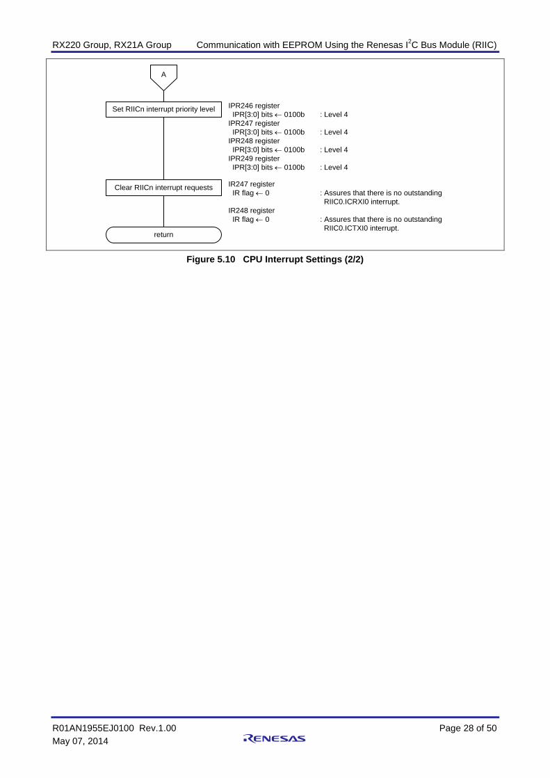
5.12.4 CPU Interrupt Settings Figure 5.9 and Figure 5.10 shows the flowchart for CPU interrupt settings.
CpuIntCreate
Disable RIICn interrupt requests (ICU)
IER1E register IEN6 bit ← 0 : Disables the RIIC0.ICEEI0 interrupt requests IEN7 bit ← 0 : Disables the RIIC0.ICRXI0 interrupt requestsIER1F register IEN0 bit ← 0 : Disables the RIIC0.ICTXI0 interrupt requests IEN1 bit ← 0 : Disables the RIIC0.ICTEI0 interrupt requests
Disable RIICn interrupts RIIC0.ICIER register ← 00h TIE bit = 0 : Disables the TXI interrupts TEIE bit = 0 : Disables the TEI interrupts RIE bit = 0 : Disables the REI interrupts NAKIE bit = 0 : Disables the NACK reception interrupt. SPIE bit = 0 : Disables the stop condition detected interrupt. STIE bit = 0 : Disables the start condition detected interrupt. ALIE bit = 0 : Disables the arbitration lost interrupt. TMOIE bit = 0 : Disables the timeout interrupt.
Enable writing to PFSWE bit MPC.PWPR register B0WI bit ← 0
Enable writing to PFS register MPC.PWPR register PFSWE bit ← 1
Select pin functions MPC.P12PFS register ← 0Fh PSEL[3:0] bits = 1111b : SCLMPC.P13PFS register ← 0Fh PSEL[3:0] bits = 1111b : SDA
Disable writing to PFS register MPC.PWPR register PFSWE bit ← 0
Disable writing to PFSWE bit MPC.PWPR register B0WI bit ← 1
Set port modes PORT1.PMR register B2 bit ← 1 : SCL: Used as a peripheral function B3 bit ← 1 : SDA: Used as a peripheral function
A
Figure 5.9 CPU Interrupt Settings (1/2)
RX220 Group, RX21A Group Communication with EEPROM Using the Renesas I2C Bus Module (RIIC)
R01AN1955EJ0100 Rev.1.00 Page 28 of 50 May 07, 2014
return
Clear RIICn interrupt requests IR247 register IR flag ← 0 : Assures that there is no outstanding
RIIC0.ICRXI0 interrupt.IR248 register IR flag ← 0 : Assures that there is no outstanding
RIIC0.ICTXI0 interrupt.
Set RIICn interrupt priority level IPR246 register IPR[3:0] bits ← 0100b : Level 4IPR247 register IPR[3:0] bits ← 0100b : Level 4IPR248 register IPR[3:0] bits ← 0100b : Level 4IPR249 register IPR[3:0] bits ← 0100b : Level 4
A
Figure 5.10 CPU Interrupt Settings (2/2)

RX220 Group, RX21A Group Communication with EEPROM Using the Renesas I2C Bus Module (RIIC)
R01AN1955EJ0100 Rev.1.00 Page 29 of 50 May 07, 2014
5.12.5 Sample EEPROM Write Processing Figure 5.11 shows the flowchart for sample EEPROM write processing.
SampleEepromWrite
Transmit data settings Sets up the sample transmit data (0x00, 0x01, 0x02, ...).
return
Set the EEPROMmemory address
Sets the EEPROM write address (0x0000).
Set up the IIC_EepWrite()argument buffer
Sets up the argument data for IIC_EepWrite(). EEPROM slave address, memory address length, memory address storage buffer pointer, transmit data count, and transmit data storage buffer pointer
Has IICcommunication
completed?
Yes
No
Check IIC statusIIC_GetStatus()
IIC Bus free?
Yes
No
Check IIC statusIIC_GetStatus()
Waits for the completion of data transmission to EEPROM.
Waits for the IIC bus free state.
EEPROM write processingIIC_EeWrite()
Figure 5.11 Sample EEPROM Write Processing

RX220 Group, RX21A Group Communication with EEPROM Using the Renesas I2C Bus Module (RIIC)
R01AN1955EJ0100 Rev.1.00 Page 30 of 50 May 07, 2014
5.12.6 Sample EEPROM Read Processing Figure 5.12 shows the flowchart for sample EEPROM read processing.
SampleEepromRead
Clear the receive data buffer Clears the receive data buffer.
EEPROM read processingIIC_RandomRead()
return
Set the EEPROMmemory address
Sets the address data for reading from EEPROM (0x0000)
Set up the IIC_RandomRead()argument buffer
Sets up the argument data for IIC_RandomRead(). EEPROM slave address, memory address length, memory address storage buffer pointer, receive data count, and receive data storage buffer pointer
Has IIC communication
completed?
Yes
No
Check IIC statusIIC_GetStatus()
IIC Bus free?
Yes
No
Check IIC statusIIC_GetStatus()
Waits until the data read from EEPROM completes.
Waits for the IIC bus free state.
Figure 5.12 Sample EEPROM Read Processing

RX220 Group, RX21A Group Communication with EEPROM Using the Renesas I2C Bus Module (RIIC)
R01AN1955EJ0100 Rev.1.00 Page 31 of 50 May 07, 2014
5.12.7 Acknowledge Polling Figure 5.13 shows the flowchart for acknowledge polling.
IICAckPolling
Set the EEPROMmemory address Sets the EEPROM write address (0x0000).
return
Set up the IIC_EepWrite()argument buffer
Sets up the argument data for IIC_EepWrite(). EEPROM slave address
Has IIC communication
completed?
Yes
No
Check IIC statusIIC_GetStatus()
NACK response?
Yes
No
Starts acknowledge polling.
Waits for IIC communication to complete.
ACK response?
Wait for the interval requiredfor the next acknowledge
polling operation
Have the specified number of iterations
completed?
No
Yes
Yes
Iterates acknowledge polling either until anACK response is received or until the specifiediteration count completes.
During each iteration, the function waits for theinterval specified in the argument.
No
[Argument]uint8_t in_addr1 : Slave addressuint8_t in_num : Acknowledge polling repeat countunit32_t in_len : Acknowledge polling interval time
EEPROM write processingIIC_EeWrite()
Figure 5.13 Acknowledge Polling

RX220 Group, RX21A Group Communication with EEPROM Using the Renesas I2C Bus Module (RIIC)
R01AN1955EJ0100 Rev.1.00 Page 32 of 50 May 07, 2014
5.12.8 IIC Processing Setup Figure 5.14 shows the flowchart for IIC processing setup.
IIC_Create
Set SCL and SDA pins to not driven state
return
Set timeout RIIC0.ICMR2 register TMOL bit = 0 : Counting is disabled when the SCL line is low. TMOH bit = 1 : Counting is enabled when the SCL line is high. TMOS bit = 0 : Long mode (timeout detection time)
Clear ACKBT write protect RIIC0.ICMR3 register ACKWP bit = 1 : Enables writing to the ACKBT bit.
(This is to provide NACK responses in EEPROM read processing.)
Initialize RIIC internally used RAM Initialize RIIC internally used RAM
Clear internal reset state RIIC0.ICCR1 register IICRST bit ← 0
Set up RIICn interrupts RIIC0.ICIER register ← BBh TIE bit = 1 : Enables the TXI interrupt. TEIE bit = 0 : Disables the TEI interrupt. RIE bit = 1 : Enables the REI interrupt. NAKIE bit = 1 : Enables the NACK received interrupt. SPIE bit = 1 : Enables the stop condition detected interrupt. STIE bit = 0 : Disables the start condition detected interrupt. ALIE bit = 1 : Enables the arbitration lost interrupt. TMOIE bit = 1 : Enables the timeout interrupt.
RIIC reset
Internal reset
RIIC0.ICCR1 register ICE bit ← 0
RIIC0.ICCR1 register IICRST bit ← 1
RIIC0.ICCR1 register ICE bit ← 1
Invalidate slave address RIIC0.ICSER register ← 00h SAROE bit = 0 : Invalidates the SARL0 and SARU0 settings
Set communication bit rate RIIC0.ICMR1 register CKS bit = 0 : Internal reference clock PCLK/1 clock cycleRIIC0.ICBRH register BRH bit = 11 : High-level width for the bit rateRIIC0.ICBRL register BRL bit = 25 : Low-level width for the bit rate
Enable writing to timeout function internal counter
RIIC0.ICMR2 register TMWE bit = 1 : Enables writing to the timeout function internal counter.
Initialize timeout function internal counter
Enable timeout detection function
RIIC0.TMOCNTL register ← 00hRIIC0.TMOCNTU register ← 00h
RIIC0.ICFER register TMOE bit ← 1
CPU interrupt settingCpuIntCreate()
Enable RIICn interrupt requests (ICU)
IER1E register IEN6 bit ← 1 : Enables the RIIC0.ICEEI0 interrupt requests. IEN7 bit ← 1 : Enables the RIIC0.ICRXI0 interrupt requests.IER1F register IEN0 bit ← 1 : Enables the RIIC0.ICTXI0 interrupt requests. IEN1 bit ← 1 : Enables the RIIC0.ICTEI0 interrupt requests.
Figure 5.14 IIC Processing Setup

RX220 Group, RX21A Group Communication with EEPROM Using the Renesas I2C Bus Module (RIIC)
R01AN1955EJ0100 Rev.1.00 Page 33 of 50 May 07, 2014
5.12.9 IIC Termination Processing Figure 5.15 shows the flowchart for IIC termination processing.
IIC_Destroy
return
Set SCL and SDA pins to not driven state
RIIC reset
Clear internal reset state
RIIC0.ICCR1 register ICE bit ← 0
RIIC0.ICCR1 register IICRST bit ← 1
RIIC0.ICCR1 register IICRST bit ← 0
Figure 5.15 IIC Termination Processing
5.12.10 EEPROM Write Start Processing Figure 5.16 shows the flowchart for EEPROM write start processing.
IIC_EeWrite
return(RIIC_OK)
Is this devicecommunicating?
Yes
Store the argumentin the IIC buffer
Generate a start condition
return(RIIC_MODE_ERROR)
Is the bus free?
Yes
Set internal RAM modeand the counter
return(RIIC_BUS_BUSY)
No
No
Checks the internal mode.Cancels the write if a communicationoperation is in progress.
Checks the IIC bus state.Cancels the write if the bus is busy.
Stores the argument in the IIC buffer.
Sets up internal RAM mode.Sets the internal mode and the counter.
RIIC0.ICCR2 register ST bit ← 1
[Argument]iic_api_t data1 uint8_t SlvAdr : Slave address uint16_t PreCnt : Memory address counter unit8_t *pPreData : Memory address storage buffer pointer uint32_t RWCnt : Data count uint8 _t *pRWData : Data storage buffer pointer
Figure 5.16 EEPROM Write Start Processing

RX220 Group, RX21A Group Communication with EEPROM Using the Renesas I2C Bus Module (RIIC)
R01AN1955EJ0100 Rev.1.00 Page 34 of 50 May 07, 2014
5.12.11 EEPROM Read Start Processing Figure 5.17 shows the flowchart for EEPROM read start processing.
IIC_RandomRead
return(RIIC_OK)
Is this devicecommunicating?
Yes
Store the argumentin the IIC buffer
Generate a start condition
return(RIIC_MODE_ERROR)
Is the bus free?
Yes
Set internal RAM modeand the counter
return(RIIC_BUS_BUSY)
No
No
Checks the internal mode.Cancels the write if a communicationoperation is in progress.
Checks the IIC bus state.Cancels the write if the bus is busy.
Stores the argument in the IIC buffer.
Sets up internal RAM mode.Sets the internal mode and the counter.
Is the argument legal?
Yesreturn
(RIIC_PMR_ERROR)
No Checks the argument value.Cancels the read if the value is illegal.
RIIC0.ICCR2 register ST bit ← 1
[Argument]iic_api_t data1 uint8_t SlvAdr : Slave address uint16_t PreCnt : Memory address counter unit8_t *pPreData : Memory address storage buffer pointer uint32_t RWCnt : Data count uint8 _t *pRWData : Data storage buffer pointer
Figure 5.17 EEPROM Read Start Processing

RX220 Group, RX21A Group Communication with EEPROM Using the Renesas I2C Bus Module (RIIC)
R01AN1955EJ0100 Rev.1.00 Page 35 of 50 May 07, 2014
5.12.12 IIC Status Check Figure 5.18 shows the flowchart for IIC status check.
IIC_GetStatus
return
Check the IIC bus status
Check the IIC status Stores the IIC status int the buffer indicated by the argument.
Stores the IIC bus state (bus busy or bus free) in the buffer indicated by the argument.
[Argument]enum riic_status_t *data1 : IIC statusenum riic_bus_status_t *data2 : IIC bus status
Figure 5.18 IIC Status Check
RX220 Group, RX21A Group Communication with EEPROM Using the Renesas I2C Bus Module (RIIC)
R01AN1955EJ0100 Rev.1.00 Page 36 of 50 May 07, 2014
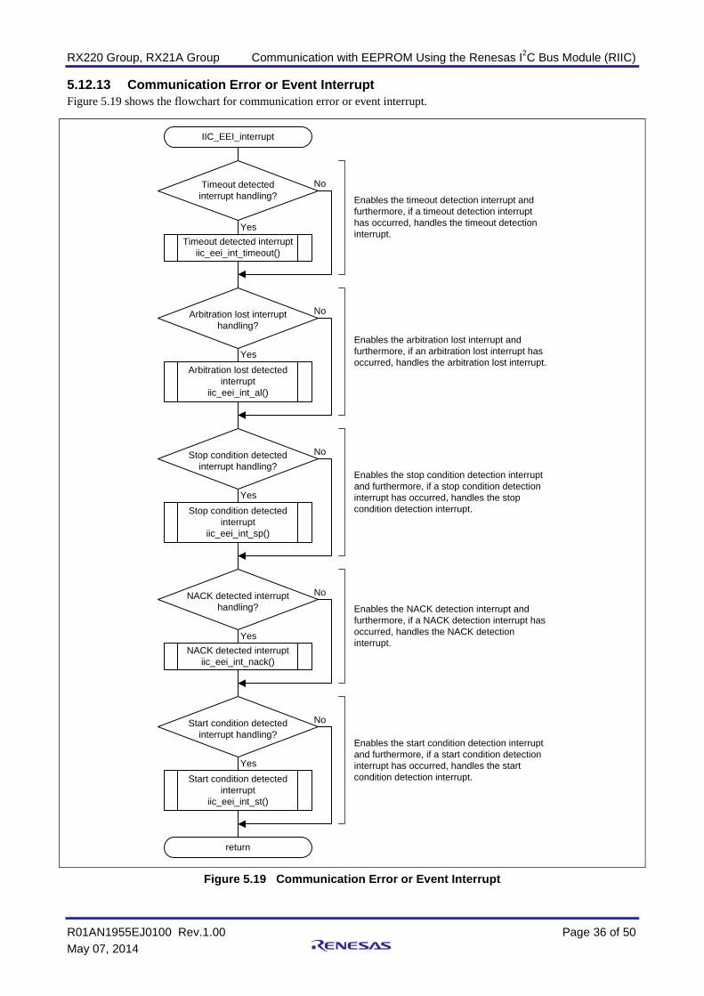
5.12.13 Communication Error or Event Interrupt Figure 5.19 shows the flowchart for communication error or event interrupt.
IIC_EEI_interrupt
return
Timeout detectedinterrupt handling?
Yes
No
Timeout detected interruptiic_eei_int_timeout()
Enables the timeout detection interrupt andfurthermore, if a timeout detection interrupthas occurred, handles the timeout detectioninterrupt.
Arbitration lost interrupt handling?
Yes
No
Arbitration lost detectedinterrupt
iic_eei_int_al()
Enables the arbitration lost interrupt andfurthermore, if an arbitration lost interrupt hasoccurred, handles the arbitration lost interrupt.
Stop condition detected interrupt handling?
Yes
No
Stop condition detectedinterrupt
iic_eei_int_sp()
Enables the stop condition detection interruptand furthermore, if a stop condition detectioninterrupt has occurred, handles the stopcondition detection interrupt.
NACK detected interrupt handling?
Yes
No
NACK detected interruptiic_eei_int_nack()
Enables the NACK detection interrupt andfurthermore, if a NACK detection interrupt hasoccurred, handles the NACK detectioninterrupt.
Start condition detected interrupt handling?
Yes
No
Start condition detectedinterrupt
iic_eei_int_st()
Enables the start condition detection interruptand furthermore, if a start condition detectioninterrupt has occurred, handles the startcondition detection interrupt.
Figure 5.19 Communication Error or Event Interrupt

RX220 Group, RX21A Group Communication with EEPROM Using the Renesas I2C Bus Module (RIIC)
R01AN1955EJ0100 Rev.1.00 Page 37 of 50 May 07, 2014
5.12.14 Timeout Detection Interrupt Figure 5.20 shows the flowchart for timeout detection interrupt.
iic_eei_int_timeout
return
Stop condition generationprocessing used
when an abnormality occursiic_gen_clk_sp()
Figure 5.20 Timeout Detection Interrupt
5.12.15 Arbitration Lost Detected Interrupt Figure 5.21 shows the flowchart for arbitration lost detected interrupt.
iic_eei_int_al
return
Stop condition generationprocessing used
when an abnormality occursiic_gen_clk_sp()
Figure 5.21 Arbitration Lost Detected Interrupt

RX220 Group, RX21A Group Communication with EEPROM Using the Renesas I2C Bus Module (RIIC)
R01AN1955EJ0100 Rev.1.00 Page 38 of 50 May 07, 2014
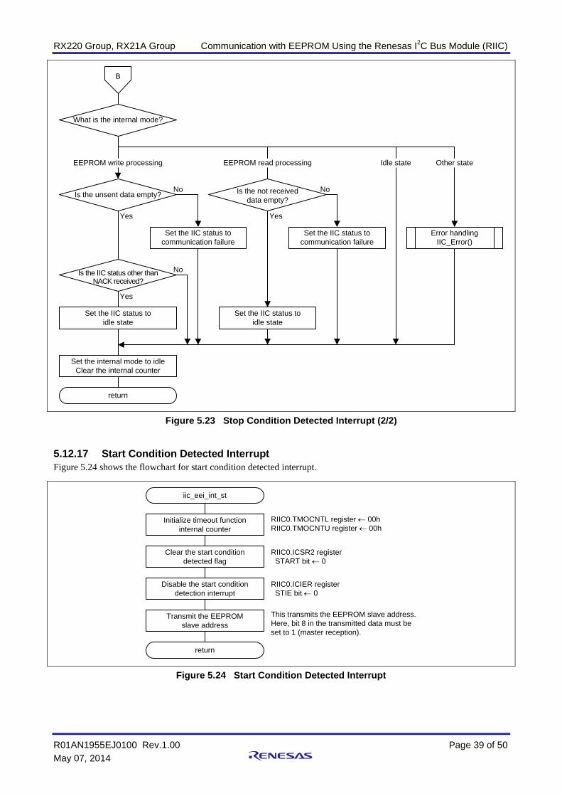
5.12.16 Stop Condition Detected Interrupt Figures 5.22 and 5.23 shows the flowchart for stop condition detected interrupt.
iic_eei_int_sp
Clear NACK detected flag
Clear stop condition detected flag
RIIC0.ICSR2 register NACKF bit ← 0
RIIC0.ICSR2 register STOP bit ← 0
Set up RIICn interrupt RIIC0.ICIER register ← BBh TIE bit = 1 : Enables the TXI interrupt. TEIE bit = 0 : Disables the TEI interrupt. RIE bit = 1 : Enables the REI interrupt. NAKIE bit = 1 : Enables the NACK received interrupt. SPIE bit = 1 : Enables the stop condition detected interrupt. STIE bit = 0 : Disables the start condition detected interrupt. ALIE bit = 1 : Enables the arbitration lost interrupt. TMOIE bit = 1 : Enables the timeout interrupt.
Initialize timeout function internal counter
RIIC0.TMOCNTL register ← 00hRIIC0.TMOCNTU register ← 00h
EEPROM readprocessing mode?
Select RDRF flag set timing RIIC0.ICMR3 register RDRFS bit = 0 : Becomes 1 on the rise of the 9th clock cycle of
the SCL clock.
Issue 0 as acknowledge bit RIIC0.ICMR3 register ACKBT bit ← 0
Yes
B
No
Figure 5.22 Stop Condition Detected Interrupt (1/2)
RX220 Group, RX21A Group Communication with EEPROM Using the Renesas I2C Bus Module (RIIC)
R01AN1955EJ0100 Rev.1.00 Page 39 of 50 May 07, 2014
return
Yes
No
What is the internal mode?
Is the unsent data empty?
Is the IIC status other than NACK received?
Set the IIC status toidle state
Set the IIC status tocommunication failure
Is the not receiveddata empty?
Set the IIC status tocommunication failure
Set the IIC status toidle state
Error handlingIIC_Error()
EEPROM write processing EEPROM read processing Other stateIdle state
Set the internal mode to idleClear the internal counter
No
YesYes
No
B
Figure 5.23 Stop Condition Detected Interrupt (2/2)
5.12.17 Start Condition Detected Interrupt Figure 5.24 shows the flowchart for start condition detected interrupt.
iic_eei_int_st
return
Clear the start conditiondetected flag
Disable the start condition detection interrupt
RIIC0.ICSR2 register START bit ← 0
RIIC0.ICIER register STIE bit ← 0
Transmit the EEPROMslave address
This transmits the EEPROM slave address.Here, bit 8 in the transmitted data must be set to 1 (master reception).
Initialize timeout functioninternal counter
RIIC0.TMOCNTL register ← 00hRIIC0.TMOCNTU register ← 00h
Figure 5.24 Start Condition Detected Interrupt

RX220 Group, RX21A Group Communication with EEPROM Using the Renesas I2C Bus Module (RIIC)
R01AN1955EJ0100 Rev.1.00 Page 40 of 50 May 07, 2014
5.12.18 NACK Detected Interrupt Figure 5.25 shows the flowchart for NACK detected interrupt.
iic_eei_int_nack
return
Set the internal status toNACK received
Disable the NACK detection interrupt
RIIC0.ICIER register NAKIE bit ← 0
Generate a stop conditon RIIC0.ICCR2 register SP bit ← 1
Clear the stop conditiondetected flag
RIIC0.ICSR2 register STOP bit ← 0
EEPROM readprocessing mode?
Perform dummy read of ICDRR
Yes
No
Disable transmit complete interrupt
RIIC0.ICIER register TEIE bit ← 0
Figure 5.25 NACK Detected Interrupt
5.12.19 Receive Data Full Interrupt Figure 5.26 shows the flowchart for receive data full interrupt.
IIC_RXI_interrupt
return
What is the internal mode?
EEPROM read processing EEPROM write processing Other state
Error handlingiic_error()
Error handlingiic_error()
Initialize timeout functioninternal counter
RIIC0.TMOCNTL register ← 00hRIIC0.TMOCNTU register ← 00h
EEPROM read processingiic_rxi_int_eeread()
Figure 5.26 Receive Data Full Interrupt

RX220 Group, RX21A Group Communication with EEPROM Using the Renesas I2C Bus Module (RIIC)
R01AN1955EJ0100 Rev.1.00 Page 41 of 50 May 07, 2014
5.12.20 EEPROM Read Processing (Master Reception Section) Figure 5.27 shows the flowchart for EEPROM read processing (master reception section).
iic_rxi_int_eeread
return
Interrupt after slaveaddress reception?
Increment internal counter This counter counts the number ofreceived data items.
Is remaining data toread count 2?
Is remaining data toread count 1?
ICDRR read
Issue 1 as acknowledge bit(RIIC0.ICMR3.ACKBT ← 1)
ICDRR read
No
Yes
No
NoNo
Yes
Yes
Yes
Select RDRF flag set timing(RIIC0.ICMR3.RDRFS ← 1)
Last data reception?No
Clear the stop conditiondetected flag
(RIIC0.ICSR2.STOP ← 0)
Prepare to generatea stop conditon
(RIIC0.ICCR2.SP ← 1)
ICDRR read(Read out final receive data and generate stop condition)
Issue 1 as acknowledge bit(RIIC0.ICMR3.ACKBT ← 1)
Yes
After generating 9th clock cycle, clear hold SCL = low setting(RIIC0.ICMR3.WAIT ← 0)
ICDRR read
After generating 9th clock cycle, clear hold SCL = low setting(RIIC0.ICMR3.WAIT ← 1)
Perform dummy read of ICDRR
After generating 9th clock cycle, clear hold SCL = low setting(RIIC0.ICMR3.WAIT ← 1)
Is remaining data toread count 1?
No
Yes
Last data reception?
Initialize timeout function internal counter
Issue 1 as acknowledge bit(RIIC0.ICMR3.ACKBT ← 1)
Select RDRF flag set timing(RIIC0.ICMR3.RDRFS ← 1)
After generating 9th clock cycle, clear hold SCL = low setting(RIIC0.ICMR3.WAIT ← 1)
Figure 5.27 EEPROM Read Processing (Master Reception Section)

RX220 Group, RX21A Group Communication with EEPROM Using the Renesas I2C Bus Module (RIIC)
R01AN1955EJ0100 Rev.1.00 Page 42 of 50 May 07, 2014
5.12.21 Transmit Data Empty Interrupt Figure 5.28 shows the flowchart for transmit data empty interrupt.
IIC_TXI_interrupt
return
What is the internal mode?
EEPROM write processing EEPROM read processing Other state
Error handlingiic_error()
Initialize timeout functioninternal counter
RIIC0.TMOCNTL register ← 00hRIIC0.TMOCNTU register ← 00h
EEPROM write processingiic_txi_int_eewrite()
EEPROM read processingiic_txi_int_eeread()
Figure 5.28 Transmit Data Empty Interrupt
5.12.22 EEPROM Write Processing Figure 5.29 shows the flowchart for EEPROM write processing.
iic_txi_int_eewrite
return
Slave addresstransmission?
Increment internal counter This counter counts the number of transmitted data items.
Memory addresstransmission?
Write datatransmission?
No
Yes
No
NoYes
Yes
Transmit the slave address
Transmit the memory address
Transmit the data
Enable the transmissioncomplete interrupt
Figure 5.29 EEPROM Write Processing

RX220 Group, RX21A Group Communication with EEPROM Using the Renesas I2C Bus Module (RIIC)
R01AN1955EJ0100 Rev.1.00 Page 43 of 50 May 07, 2014
5.12.23 EEPROM Read Processing (Master Transmission Section) Figure 5.30 shows the flowchart for EEPROM read processing (master transmission section).
iic_txi_int_eeread
return
Slave addresstransmission?
Increment internal counter This counter counts the number of transmitted data items.
Memory addresstransmission?
No
No
Yes
Yes
Transmit the slave address
Transmit the memory address
Enable the transmissioncomplete interrupt
Figure 5.30 EEPROM Read Processing (Master Transmission Section)
5.12.24 Transmission Complete Interrupt Figure 5.31 shows the flowchart for transmission complete interrupt.
IIC_TEI_interrupt
return
What is the internal mode?
Transmission end processingused after an EEPROM write
iic_tei_int_eewrite()
EEPROM write processing EEPROM read processing Other state
Transmission end processingused after an EEPROM read
iic_tei_int_eeread()
Error handlingiic_error()
Enable the transmissioncomplete interrupt
RIIC0.TMOCNTL register ← 00hRIIC0.TMOCNTU register ← 00h
Figure 5.31 Transmission Complete Interrupt

RX220 Group, RX21A Group Communication with EEPROM Using the Renesas I2C Bus Module (RIIC)
R01AN1955EJ0100 Rev.1.00 Page 44 of 50 May 07, 2014
5.12.25 Transmission End Processing Used After an EEPROM Write Figure 5.32 shows the flowchart for transmission end processing used after an EEPROM write.
iic_tei_int_eewrite
return
Clear the stop conditiondetected flag
Disable the transmissioncomplete interrupt
RIIC0.ICSR2 register STOP bit ← 0
RIIC0.ICIER register TEIE bit ← 0
Generate a stop condition RIIC0.ICCR2 register SP bit ← 1
Figure 5.32 Transmission End Processing Used After an EEPROM Write
5.12.26 Transmission End Processing Used After an EEPROM Read Figure 5.33 shows the flowchart for transmission end processing used after an EEPROM read.
iic_tei_int_eeread
return
Clear the start conditiondetected flag
Enable start condition detected interrupt request
RIIC0.ICSR2 register START bit ← 0
RIIC0.ICIER register STIE bit ← 0
Generate a restart condition RIIC0.ICCR2 register RS bit ← 1
Disable transmit complete interrupt
RIIC0.ICIER register TEIE bit ← 0
Figure 5.33 Transmission End Processing Used After an EEPROM Read

RX220 Group, RX21A Group Communication with EEPROM Using the Renesas I2C Bus Module (RIIC)
R01AN1955EJ0100 Rev.1.00 Page 45 of 50 May 07, 2014
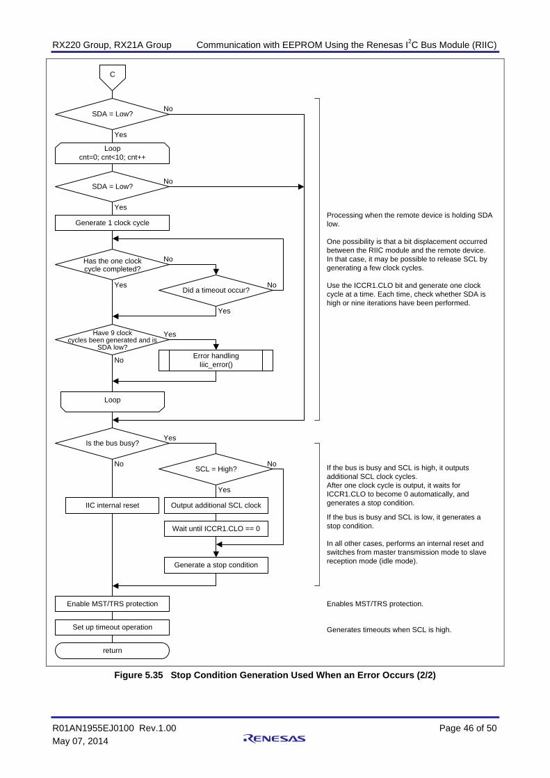
5.12.27 Stop Condition Generation Used When an Error Occurs Figure 5.34 and Figure 5.35 shows the flowchart for stop condition generation used when an error occurs.
iic_gen_clk_sp
Internal reset Stops output to SCL and SDA and resets theinternal state.
Error handlingiic_error()
Set up timeout operation Generates timeouts on SCL = high or SCL = low.
Wait for a fixed period Waits for the SCL and SDA release timesdue to the internal reset.
Enable timeouts Enables timeouts.
SCL = High?
Yes
No
Set up master mode Clears MST/TRS protection and sets up mastertransmission mode.
C
Even though an internal reset was performed, SCL was set high while another device was holding it low.
Figure 5.34 Stop Condition Generation Used When an Error Occurs (1/2)
RX220 Group, RX21A Group Communication with EEPROM Using the Renesas I2C Bus Module (RIIC)
R01AN1955EJ0100 Rev.1.00 Page 46 of 50 May 07, 2014
Enables MST/TRS protection.
SDA = Low?
Yes
No
Loopcnt=0; cnt<10; cnt++
SDA = Low?
Yes
No
Generate 1 clock cycle
Has the one clockcycle completed?
Yes
No
Did a timeout occur?
Yes
No
Have 9 clockcycles been generated and is
SDA low?
Yes
No Error handlingIiic_error()
Loop
C
return
Is the bus busy?Yes
No
IIC internal reset
Enable MST/TRS protection
Set up timeout operation
Generate a stop condition
Processing when the remote device is holding SDA low.
One possibility is that a bit displacement occurredbetween the RIIC module and the remote device.In that case, it may be possible to release SCL bygenerating a few clock cycles.
Use the ICCR1.CLO bit and generate one clock cycle at a time. Each time, check whether SDA is high or nine iterations have been performed.
If the bus is busy and SCL is high, it outputs additional SCL clock cycles.After one clock cycle is output, it waits for ICCR1.CLO to become 0 automatically, and generates a stop condition.
If the bus is busy and SCL is low, it generates a stop condition.
In all other cases, performs an internal reset andswitches from master transmission mode to slavereception mode (idle mode).
Generates timeouts when SCL is high.
SCL = High?
Yes
Output additional SCL clock
Wait until ICCR1.CLO == 0
No
Figure 5.35 Stop Condition Generation Used When an Error Occurs (2/2)

RX220 Group, RX21A Group Communication with EEPROM Using the Renesas I2C Bus Module (RIIC)
R01AN1955EJ0100 Rev.1.00 Page 47 of 50 May 07, 2014
5.12.28 Error Handling Figure 5.36 shows the flowchart for error handling.
iic_error [Argument]enum riic_err_code_t error_code : IIC error code
RIIC error handling The sample code does not perform RIIC error handling. (It enters an infinite loop.) If this functionality is required, the user should add the appropriate code.
Figure 5.36 Error Handling
5.12.29 RIICn.EEIn Interrupt Handler (Level Detection Interrupt) Figure 5.37 shows the flowchart for RIICn.EEIn interrupt handler (level detection interrupt).
Excep_RIICn_EEIn
return
Communication error orevent interrupt
IIC_EEI_interrupt()
Figure 5.37 RIICn.EEIn Interrupt Handler (Level Detection Interrupt)
5.12.30 RIICn.RXIn Interrupt Handler (Edge Detection Interrupt) Figure 5.38 shows the flowchart for RIICn.RXIn interrupt handler (edge detection interrupt).
Excep_RIICn_RXIn
return
Receive data full interruptIIC_RXI_interrupt()
Figure 5.38 RIICn.RXIn Interrupt Handler (Edge Detection Interrupt)
5.12.31 RIICn.TXIn Interrupt Handler (Edge Detection Interrupt) Figure 5.39 shows the flowchart for RIICn.TXIn interrupt handler (edge detection interrupt).
Excep_RIICn_TXIn
return
Transmit data emptyinterrupt
IIC_TXI_interrupt()
Figure 5.39 RIICn.TXIn Interrupt Handler (Edge Detection Interrupt)

RX220 Group, RX21A Group Communication with EEPROM Using the Renesas I2C Bus Module (RIIC)
R01AN1955EJ0100 Rev.1.00 Page 48 of 50 May 07, 2014
5.12.32 RIICn.TEIn Interrupt Handler (Level Detection Interrupt) Figure 5.40 shows the flowchart for RIICn.TEIn interrupt handler (level detection interrupt).
Excep_RIICn_TEIn
return
Transmission completeinterrupt
IIC_TEI_interrupt()
Figure 5.40 RIICn.TEIn Interrupt Handler (Level Detection Interrupt)

RX220 Group, RX21A Group Communication with EEPROM Using the Renesas I2C Bus Module (RIIC)
R01AN1955EJ0100 Rev.1.00 Page 49 of 50 May 07, 2014
6. Sample Code The sample code can be downloaded from the Renesas Electronics Corporation web site.
7. Usage Notes
7.1 Sample Code Usage Notes Either an RX220 Group or an RX21A Group device can be selected in the sample code. Use the following settings when selecting the device.
1. In the project tab in the workspace window in the High-performance Embedded Workshop, set the project for the device to be used to be the active project. Refer to the latest version of the High-performance Embedded Workshop user’s manual for the procedure for setting the active project.
Figure 7.1 Setting the Active Project
2. Select the device used in the device configuration file (iic_eeprom_cfg.h). Uncomment the code for the device used and comment out the codes for unused devices.
7.2 Board Usage Notes Keep the following points in mind when verifying the operation of the sample code for the board used as stipulated in this application note.
Board used: Hokuto Denshi Co., Ltd. HSB Series microcontroller boards (Product Part Number: HSBRX21AP-B)
No EEPROM is mounted on the Hokuto Denshi Co., Ltd. HSB Series microcontroller boards. To verify operation, EEPROM must be provided separately.

RX220 Group, RX21A Group Communication with EEPROM Using the Renesas I2C Bus Module (RIIC)
R01AN1955EJ0100 Rev.1.00 Page 50 of 50 May 07, 2014
8. Reference Documents User’s Manual: Hardware
RX220 Group User’s Manual: Hardware Rev.1.00 (R01UH0292EJ) RX21A Group User’s Manual: Hardware Rev.1.00 (R01UH0251EJ) The latest version can be downloaded from the Renesas Electronics website.
Technical Update / Technical News
The latest information can be downloaded from the Renesas Electronics website.
User’s Manual: Development Tools RX Family C/C++ Compiler Package V.1.01 User’s Manual Rev.1.00 (R20UT0570EJ) The latest version can be downloaded from the Renesas Electronics website. High-performance Embedded Workshop V.4.09 User’s Manual Rev.1.00 (R20UT0372EJ) The latest version can be downloaded from the Renesas Electronics website.
Datasheets: EEPROM
R1EX24016ASAS0A Datasheet V.1.00 Rev.1.00 (rej03c270_r1ex24016axxs0abs) R1EX24512ASAS0A Datasheet V.1.00 Rev.1.00 (rej03c249_r1ex24512axxs0abs) The latest version can be downloaded from the Renesas Electronics website.
Website and Support Renesas Electronics Website
http://www.renesas.com/ Inquiries
http://www.renesas.com/contact/
All trademarks and registered trademarks are the property of their respective owners.

A-1
Revision History
Rev. Date Description Page Summary
1.00 May 07, 2014 — First edition issued

General Precautions in the Handling of MPU/MCU Products The following usage notes are applicable to all MPU/MCU products from Renesas. For detailed usage notes on the products covered by this document, refer to the relevant sections of the document as well as any technical updates that have been issued for the products.
1. Handling of Unused Pins Handle unused pins in accord with the directions given under Handling of Unused Pins in the manual. The input pins of CMOS products are generally in the high-impedance state. In operation with an
unused pin in the open-circuit state, extra electromagnetic noise is induced in the vicinity of LSI, an associated shoot-through current flows internally, and malfunctions occur due to the false recognition of the pin state as an input signal become possible. Unused pins should be handled as described under Handling of Unused Pins in the manual.
2. Processing at Power-on The state of the product is undefined at the moment when power is supplied. The states of internal circuits in the LSI are indeterminate and the states of register settings and
pins are undefined at the moment when power is supplied. In a finished product where the reset signal is applied to the external reset pin, the states of pins are not guaranteed from the moment when power is supplied until the reset process is completed. In a similar way, the states of pins in a product that is reset by an on-chip power-on reset function are not guaranteed from the moment when power is supplied until the power reaches the level at which resetting has been specified.
3. Prohibition of Access to Reserved Addresses Access to reserved addresses is prohibited. The reserved addresses are provided for the possible future expansion of functions. Do not access
these addresses; the correct operation of LSI is not guaranteed if they are accessed. 4. Clock Signals
After applying a reset, only release the reset line after the operating clock signal has become stable. When switching the clock signal during program execution, wait until the target clock signal has stabilized. When the clock signal is generated with an external resonator (or from an external oscillator)
during a reset, ensure that the reset line is only released after full stabilization of the clock signal. Moreover, when switching to a clock signal produced with an external resonator (or by an external oscillator) while program execution is in progress, wait until the target clock signal is stable.
5. Differences between Products Before changing from one product to another, i.e. to a product with a different type number, confirm that the change will not lead to problems. The characteristics of an MPU or MCU in the same group but having a different part number may
differ in terms of the internal memory capacity, layout pattern, and other factors, which can affect the ranges of electrical characteristics, such as characteristic values, operating margins, immunity to noise, and amount of radiated noise. When changing to a product with a different part number, implement a system-evaluation test for the given product.

Notice1. Descriptions of circuits, software and other related information in this document are provided only to illustrate the operation of semiconductor products and application examples. You are fully responsible for
the incorporation of these circuits, software, and information in the design of your equipment. Renesas Electronics assumes no responsibility for any losses incurred by you or third parties arising from the
use of these circuits, software, or information.
2. Renesas Electronics has used reasonable care in preparing the information included in this document, but Renesas Electronics does not warrant that such information is error free. Renesas Electronics
assumes no liability whatsoever for any damages incurred by you resulting from errors in or omissions from the information included herein.
3. Renesas Electronics does not assume any liability for infringement of patents, copyrights, or other intellectual property rights of third parties by or arising from the use of Renesas Electronics products or
technical information described in this document. No license, express, implied or otherwise, is granted hereby under any patents, copyrights or other intellectual property rights of Renesas Electronics or
others.
4. You should not alter, modify, copy, or otherwise misappropriate any Renesas Electronics product, whether in whole or in part. Renesas Electronics assumes no responsibility for any losses incurred by you or
third parties arising from such alteration, modification, copy or otherwise misappropriation of Renesas Electronics product.
5. Renesas Electronics products are classified according to the following two quality grades: "Standard" and "High Quality". The recommended applications for each Renesas Electronics product depends on
the product's quality grade, as indicated below.
"Standard": Computers; office equipment; communications equipment; test and measurement equipment; audio and visual equipment; home electronic appliances; machine tools; personal electronic
equipment; and industrial robots etc.
"High Quality": Transportation equipment (automobiles, trains, ships, etc.); traffic control systems; anti-disaster systems; anti-crime systems; and safety equipment etc.
Renesas Electronics products are neither intended nor authorized for use in products or systems that may pose a direct threat to human life or bodily injury (artificial life support devices or systems, surgical
implantations etc.), or may cause serious property damages (nuclear reactor control systems, military equipment etc.). You must check the quality grade of each Renesas Electronics product before using it
in a particular application. You may not use any Renesas Electronics product for any application for which it is not intended. Renesas Electronics shall not be in any way liable for any damages or losses
incurred by you or third parties arising from the use of any Renesas Electronics product for which the product is not intended by Renesas Electronics.
6. You should use the Renesas Electronics products described in this document within the range specified by Renesas Electronics, especially with respect to the maximum rating, operating supply voltage
range, movement power voltage range, heat radiation characteristics, installation and other product characteristics. Renesas Electronics shall have no liability for malfunctions or damages arising out of the
use of Renesas Electronics products beyond such specified ranges.
7. Although Renesas Electronics endeavors to improve the quality and reliability of its products, semiconductor products have specific characteristics such as the occurrence of failure at a certain rate and
malfunctions under certain use conditions. Further, Renesas Electronics products are not subject to radiation resistance design. Please be sure to implement safety measures to guard them against the
possibility of physical injury, and injury or damage caused by fire in the event of the failure of a Renesas Electronics product, such as safety design for hardware and software including but not limited to
redundancy, fire control and malfunction prevention, appropriate treatment for aging degradation or any other appropriate measures. Because the evaluation of microcomputer software alone is very difficult,
please evaluate the safety of the final products or systems manufactured by you.
8. Please contact a Renesas Electronics sales office for details as to environmental matters such as the environmental compatibility of each Renesas Electronics product. Please use Renesas Electronics
products in compliance with all applicable laws and regulations that regulate the inclusion or use of controlled substances, including without limitation, the EU RoHS Directive. Renesas Electronics assumes
no liability for damages or losses occurring as a result of your noncompliance with applicable laws and regulations.
9. Renesas Electronics products and technology may not be used for or incorporated into any products or systems whose manufacture, use, or sale is prohibited under any applicable domestic or foreign laws or
regulations. You should not use Renesas Electronics products or technology described in this document for any purpose relating to military applications or use by the military, including but not limited to the
development of weapons of mass destruction. When exporting the Renesas Electronics products or technology described in this document, you should comply with the applicable export control laws and
regulations and follow the procedures required by such laws and regulations.
10. It is the responsibility of the buyer or distributor of Renesas Electronics products, who distributes, disposes of, or otherwise places the product with a third party, to notify such third party in advance of the
contents and conditions set forth in this document, Renesas Electronics assumes no responsibility for any losses incurred by you or third parties as a result of unauthorized use of Renesas Electronics
products.
11. This document may not be reproduced or duplicated in any form, in whole or in part, without prior written consent of Renesas Electronics.
12. Please contact a Renesas Electronics sales office if you have any questions regarding the information contained in this document or Renesas Electronics products, or if you have any other inquiries.
(Note 1) "Renesas Electronics" as used in this document means Renesas Electronics Corporation and also includes its majority-owned subsidiaries.
(Note 2) "Renesas Electronics product(s)" means any product developed or manufactured by or for Renesas Electronics.
http://www.renesas.comRefer to "http://www.renesas.com/" for the latest and detailed information.
Renesas Electronics America Inc.2880 Scott Boulevard Santa Clara, CA 95050-2554, U.S.A.Tel: +1-408-588-6000, Fax: +1-408-588-6130Renesas Electronics Canada Limited1101 Nicholson Road, Newmarket, Ontario L3Y 9C3, CanadaTel: +1-905-898-5441, Fax: +1-905-898-3220Renesas Electronics Europe LimitedDukes Meadow, Millboard Road, Bourne End, Buckinghamshire, SL8 5FH, U.KTel: +44-1628-651-700, Fax: +44-1628-651-804Renesas Electronics Europe GmbHArcadiastrasse 10, 40472 Düsseldorf, Germany Tel: +49-211-65030, Fax: +49-211-6503-1327Renesas Electronics (China) Co., Ltd.7th Floor, Quantum Plaza, No.27 ZhiChunLu Haidian District, Beijing 100083, P.R.ChinaTel: +86-10-8235-1155, Fax: +86-10-8235-7679Renesas Electronics (Shanghai) Co., Ltd.Unit 301, Tower A, Central Towers, 555 LanGao Rd., Putuo District, Shanghai, China Tel: +86-21-2226-0888, Fax: +86-21-2226-0999Renesas Electronics Hong Kong LimitedUnit 1601-1613, 16/F., Tower 2, Grand Century Place, 193 Prince Edward Road West, Mongkok, Kowloon, Hong KongTel: +852-2886-9318, Fax: +852 2886-9022/9044Renesas Electronics Taiwan Co., Ltd.13F, No. 363, Fu Shing North Road, Taipei, TaiwanTel: +886-2-8175-9600, Fax: +886 2-8175-9670Renesas Electronics Singapore Pte. Ltd.80 Bendemeer Road, Unit #06-02 Hyflux Innovation Centre Singapore 339949Tel: +65-6213-0200, Fax: +65-6213-0300Renesas Electronics Malaysia Sdn.Bhd.Unit 906, Block B, Menara Amcorp, Amcorp Trade Centre, No. 18, Jln Persiaran Barat, 46050 Petaling Jaya, Selangor Darul Ehsan, MalaysiaTel: +60-3-7955-9390, Fax: +60-3-7955-9510Renesas Electronics Korea Co., Ltd.12F., 234 Teheran-ro, Gangnam-Gu, Seoul, 135-080, KoreaTel: +82-2-558-3737, Fax: +82-2-558-5141
SALES OFFICES
© 2014 Renesas Electronics Corporation. All rights reserved.Colophon 3.0