C12x/C16x/C24x/C30x
Operator’s Manual
Issue 2.0
Original Instruction053-2869

C12x/C16x/C24x/C30x Operator’s Manual Overview - 1
Overview
Chapter Contents
Serial Number Location . . . . . . . . . . . . . . . . . . . . . . 2
Intended Use . . . . . . . . . . . . . . . . . . . . . . . . . . . . . . . 3
Equipment Modification . . . . . . . . . . . . . . . . . . . . . . 3
Unit Components . . . . . . . . . . . . . . . . . . . . . . . . . . . 4
Operator Orientation. . . . . . . . . . . . . . . . . . . . . . . . . 5
Operating Area . . . . . . . . . . . . . . . . . . . . . . . . . . . . . 5
About This Manual . . . . . . . . . . . . . . . . . . . . . . . . . . 6
• Bulleted Lists. . . . . . . . . . . . . . . . . . . . . . . . . . . . . . . . . . . . . . . . . . . . . . .6
• Numbered Lists . . . . . . . . . . . . . . . . . . . . . . . . . . . . . . . . . . . . . . . . . . . . .6
Overview - 2 C12x/C16x/C24x/C30x Operator’s ManualSerial Number Location
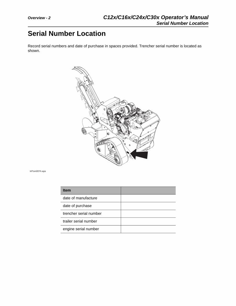
Serial Number Location
Record serial numbers and date of purchase in spaces provided. Trencher serial number is located as shown.
Item
date of manufacture
date of purchase
trencher serial number
trailer serial number
engine serial number
C12x/C16x/C24x/C30x Operator’s Manual Overview - 3
Intended Use
Intended Use
The C12x, C16x, C24x and C30x pedestrian trenchers are designed to install buried cable and pipe. The maximum trenching depth is 24” (610 mm) for C12x, 36” (915 mm) for C16x and C24x, and 48” (1220 mm) for C30x. The maximum trenching width is 6” (200 mm).
These units are intended for operation in ambient temperatures from 20° to 115°F (-7° to 46°C). Contact
your Ditch Witch® dealer for provisions required for operating in extreme temperatures. Use in any other way is considered contrary to the intended use.
C12x, C16x, C24x and C30x units should be used with genuine Ditch Witch chain, teeth, and sprockets. They should be operated, serviced, and repaired only by persons familiar with their particular characteristics and acquainted with the relevant safety procedures.
Equipment Modification
This equipment was designed and built in accordance with applicable standards and regulations. Modification of equipment could mean that it will no longer meet regulations and may not function properly or in accordance with the operating instructions. Modification of equipment should only be made by competent personnel possessing knowledge of applicable standards, regulations, equipment design functionality/requirements and any required specialized testing.
Overview - 4 C12x/C16x/C24x/C30x Operator’s ManualUnit Components
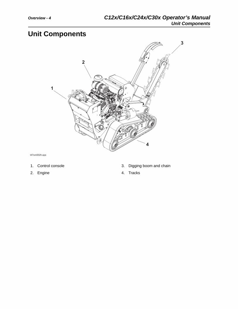
Unit Components
1. Control console
2. Engine
3. Digging boom and chain
4. Tracks
C12x/C16x/C24x/C30x Operator’s Manual Overview - 5
Operator Orientation
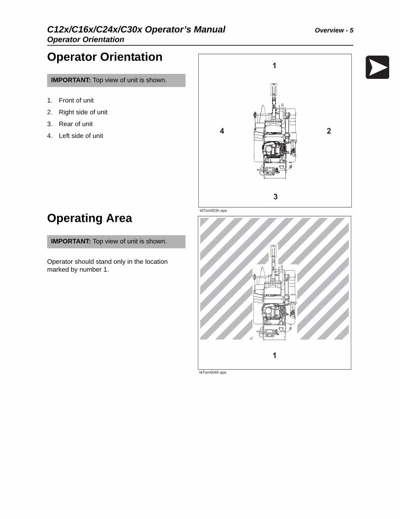
Operator Orientation
1. Front of unit
2. Right side of unit
3. Rear of unit
4. Left side of unit
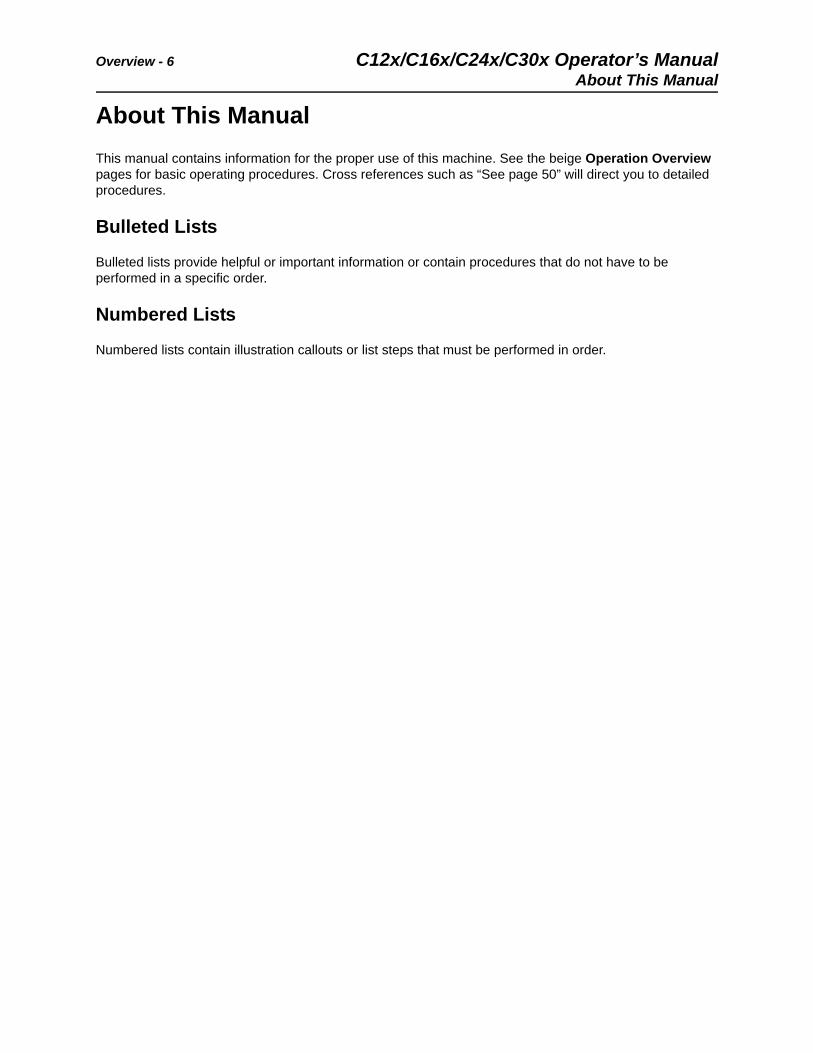
Operating Area
Operator should stand only in the location marked by number 1.
IMPORTANT: Top view of unit is shown.
IMPORTANT: Top view of unit is shown.
1
Overview - 6 C12x/C16x/C24x/C30x Operator’s ManualAbout This Manual
About This Manual
This manual contains information for the proper use of this machine. See the beige Operation Overview pages for basic operating procedures. Cross references such as “See page 50” will direct you to detailed procedures.
Bulleted Lists
Bulleted lists provide helpful or important information or contain procedures that do not have to be performed in a specific order.
Numbered Lists
Numbered lists contain illustration callouts or list steps that must be performed in order.
C12x/C16x/C24x/C30x Operator’s Manual Foreword - 7
Foreword
This manual is an important part of your equipment. It provides safety information and operation
instructions to help you use and maintain your Ditch Witch® equipment.
Read this manual before using your equipment. Keep it with the equipment at all times for future reference. If you sell your equipment, be sure to give this manual to the new owner.
If you need a replacement copy, contact your Ditch Witch dealer. If you need assistance in locating a dealer, visit our website at www.ditchwitch.com or write to the following address:
The Charles Machine Works, Inc.Attn: Marketing DepartmentPO Box 66Perry, OK 73077-0066 USA
The descriptions and specifications in this manual are subject to change without notice. The Charles Machine Works, Inc. reserves the right to improve equipment. Some product improvements may have taken place after this manual was published. For the latest information on Ditch Witch equipment, see your Ditch Witch dealer.
Thank you for buying and using Ditch Witch equipment.
Foreword - 8 C12x/C16x/C24x/C30x Operator’s Manual
C12x/C16x/C24x/C30x Operator’s Manual
Issue number 2.0/OM-11/17
Part number 053-2869
Copyright 2016, 2017
by The Charles Machine Works, Inc.
, Ditch Witch, CMW and Roto Witch are registered trademarks of The Charles Machine Works, Inc.
This product and its use may be covered by one or more patents at http://patents.charlesmachine.works.
C12x/C16x/C24x/C30x Operator’s Manual Contents - 9
Contents
Overviewmachine serial number, information about the type of work this machine is designed to perform, basic machine components, and how to use this manual
1
Forewordpart number, revision level, and publication date of this manual, and factory contact information
7
Safetymachine safety alerts and emergency procedures
11
Controlsmachine controls, gauges, and indicators and how to use them
23
Operation Overviewan overview for completing a job with this machine: planning, setting up, installing product, and restoring the jobsite; with cross references to detailed procedures
35
Prepareprocedures for inspecting and classifying the jobsite, planning the installation path, and preparing the jobsite for work
37
Driveprocedures for startup, cold start, driving, and shutdown
45
Transportprocedures for lifting, hauling, and towing
51
Trenchprocedures for trenching
59
Drillprocedures for drilling
65
Systems and Equipmentchain, teeth, sprockets, and optional equipment
79
Complete the Jobprocedures for backfilling and restoring the jobsite and rinsing and storing equipment
87
Contents - 10 C12x/C16x/C24x/C30x Operator’s Manual
Serviceservice intervals and instructions for this machine including lubrication, replacement of wear items, and basic maintenance
89
Specificationsmachine specifications including weights, measurements, power ratings, and fluid capacities
119
Supportthe warranty policy for this machine, and procedures for obtaining warranty consideration and training
133
Service Recorda record of major service performed on the machine
137
C12x/C16x/C24x/C30x Operator’s Manual Safety - 11
Safety
Chapter Contents
Guidelines . . . . . . . . . . . . . . . . . . . . . . . . . . . . . . . . 12
California Proposition 65 Warning . . . . . . . . . . . . 12
Emergency Procedures . . . . . . . . . . . . . . . . . . . . . 13
• Electric Strike Description . . . . . . . . . . . . . . . . . . . . . . . . . . . . . . . . . . . .13
• If an Electric Line is Damaged . . . . . . . . . . . . . . . . . . . . . . . . . . . . . . . .14
• If a Gas Line is Damaged . . . . . . . . . . . . . . . . . . . . . . . . . . . . . . . . . . . .15
• If a Fiber Optic Cable is Damaged . . . . . . . . . . . . . . . . . . . . . . . . . . . . .16
• If Machine Catches on Fire . . . . . . . . . . . . . . . . . . . . . . . . . . . . . . . . . . .16
Safety Alert Classification . . . . . . . . . . . . . . . . . . . 17
Machine Safety Alerts. . . . . . . . . . . . . . . . . . . . . . . 18
Safety - 12 C12x/C16x/C24x/C30x Operator’s ManualGuidelines
Guidelines
When you see this safety alert sign, carefully read and follow all instructions. YOUR SAFETY IS AT STAKE. Read this entire section before using your equipment.
Follow these guidelines before operating any jobsite equipment:
• Complete proper training and read operator’s manual before using equipment.
• Mark proposed path with white paint and have underground utilities located before working. In the US or Canada, call 811 (US) or 888-258-0808 (US and Canada). Also contact any local utilities that do not participate in the One-Call service. In countries that do not have a One-Call service, contact all local utility companies to have underground utilities located.
• Classify jobsite based on its hazards and use correct tools and machinery, safety equipment, and work methods for jobsite.
• Mark jobsite clearly and keep spectators away.
• Wear personal protective equipment.
• Review jobsite hazards, safety and emergency procedures, and individual responsibilities with all
personnel before work begins. Safety videos are available from your Ditch Witch® dealer or at www.ditchwitch.com/safe. Safety Data Sheets (SDS) are available at www.ditchwitch.com/support.
• Fully inspect equipment before operating. Repair or replace any worn or damaged parts. Replace missing or damaged safety shields and safety signs. Contact your Ditch Witch dealer for assistance.
• Use equipment carefully. Stop operation and investigate anything that does not look or feel right.
• Do not operate machine where flammable gas may be present.
• Only operate equipment in well-ventilated areas.
• Contact your Ditch Witch dealer if you have any question about operation, maintenance, or equipment use.
• Complete the equipment checklist located at www.ditchwitch.com/safe.
California Proposition 65 Warning
This product may contain chemicals known to the State of California to cause cancer, birth defects, or other reproductive harm.
• battery posts, terminals and related accessories
• engine exhaust
• ethylene glycol
C12x/C16x/C24x/C30x Operator’s Manual Safety - 13
Emergency Procedures
Emergency Procedures
Before operating any equipment, review emergency procedures and check that all safety precautions have been taken.
Electric Strike Description
When working near electric cables, remember the following:
• Electricity follows all paths to ground, not just path of least resistance.
• Pipes, hoses, and cables will conduct electricity back to all equipment.
• Low voltage current can injure or kill. Many work-related electrocutions result from contact with less than 440 volts.
Most electric strikes are not noticeable, but indications of a strike include:
• power outage
• smoke
• explosion
• popping noises
• arcing electricity
If any of these occur, assume an electric strike has occurred.
Jobsite hazards could cause death or serious injury. Use correct equipment and work methods. Use and maintain proper safety equipment.
EMERGENCY SHUTDOWN - Release all controls and stop engine.
Electric shock will cause death or serious injury. Stay away. 274-049
Safety - 14 C12x/C16x/C24x/C30x Operator’s ManualEmergency Procedures
If an Electric Line is Damaged
If you suspect an electric line has been damaged and you are near pedestrian unit, DO NOT MOVE and do not touch unit. Take the following actions. The order and degree of action will depend upon the situation.
• Warn people nearby that an electric strike has occurred. Instruct them to leave the area and contact utility.
• Do not allow anyone into area until given permission by utility company.
• Do not allow anyone to touch equipment.
C12x/C16x/C24x/C30x Operator’s Manual Safety - 15
Emergency Procedures
If a Gas Line is Damaged
If you suspect a gas line has been damaged, take the following actions. The orders and degree of action will depend on the situation.
• Immediately shut off engine(s), if this can be done safely and quickly.
• Remove any ignition source(s), if this can be done safely and quickly.
• Warn others that a gas line has been cut and that they should leave the area.
• Leave jobsite as quickly as possible.
• Immediately call your local emergency phone number and utility company.
• If jobsite is along street, stop traffic from driving near jobsite.
• Do not return to jobsite until given permission by emergency personnel and utility company.
Fire or explosion possible. Fumes could ignite and cause burns. No smoking, no flame, no spark. 275-419 (2P)
Explosion possible. Serious injury or equipment damage could occur. Follow directions carefully.
Safety - 16 C12x/C16x/C24x/C30x Operator’s ManualEmergency Procedures
If a Fiber Optic Cable is Damaged
Do not look into cut ends of fiber optic or unidentified cable. Vision damage can occur. Contact utility company.
If Machine Catches on Fire
Perform emergency shutdown procedure and then take the following actions. The order and degree of action will depend on the situation.
• Immediately move battery disconnect switch (if equipped and accessible) to disconnect position.
• If fire is small and fire extinguisher is available, attempt to extinguish fire.
• If fire cannot be extinguished, leave area as quickly as possible and contact emergency personnel.
C12x/C16x/C24x/C30x Operator’s Manual Safety - 17
Safety Alert Classifications
Safety Alert Classifications
These classifications and the icons defined on the following pages work together to alert you to situations which could be harmful to you, jobsite bystanders or your equipment. When you see these words and icons in the book or on the machine, carefully read and follow all instructions. YOUR SAFETY IS AT STAKE.
Watch for the three safety alert levels: DANGER, WARNING and CAUTION. Learn what each level means.
indicates a hazardous situation that, if not avoided, will result in death or serious injury. This signal word is to be limited to the most extreme situations.
indicates a hazardous situation that, if not avoided, could result in death or serious injury.
indicates a hazardous situation that, if not avoided, could result in minor or moderate injury.
Watch for two other words: NOTICE and IMPORTANT.
NOTICE indicates information considered important, but not hazard-related (e.g., messages relating to property damage).
IMPORTANT can help you do a better job or make your job easier in some way.
Safety - 18 C12x/C16x/C24x/C30x Operator’s ManualMachine Safety Alerts
Machine Safety Alerts
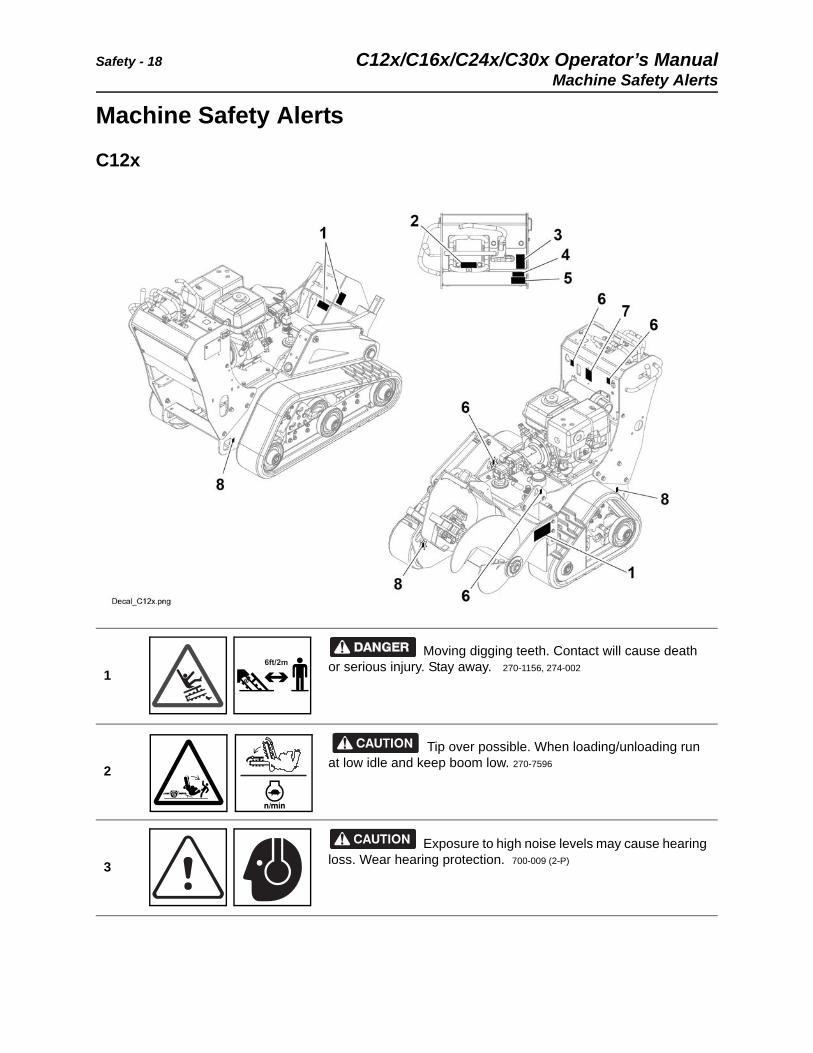
C12x
1
Moving digging teeth. Contact will cause death or serious injury. Stay away. 270-1156, 274-002
2
Tip over possible. When loading/unloading run at low idle and keep boom low. 270-7596
3
Exposure to high noise levels may cause hearing loss. Wear hearing protection. 700-009 (2-P)
6ft/2m
C12x/C16x/C24x/C30x Operator’s Manual Safety - 19
Machine Safety Alerts
4
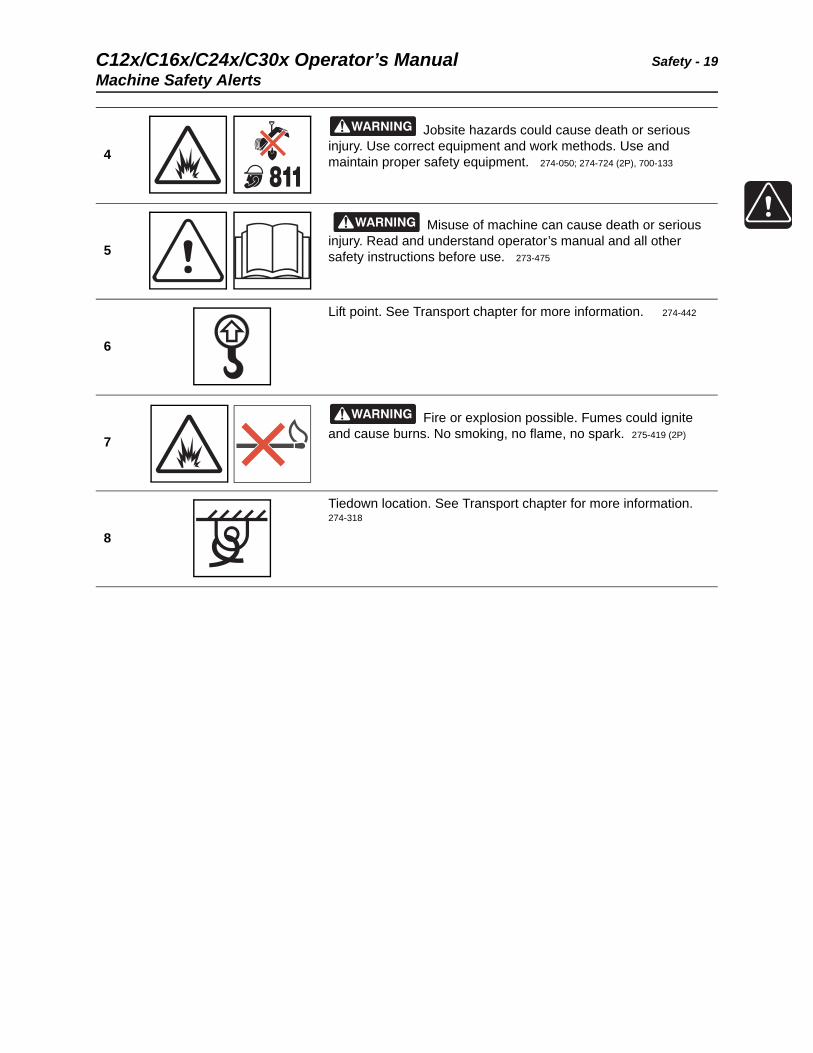
Jobsite hazards could cause death or serious injury. Use correct equipment and work methods. Use and maintain proper safety equipment. 274-050; 274-724 (2P), 700-133
5
Misuse of machine can cause death or serious injury. Read and understand operator’s manual and all other safety instructions before use. 273-475
6
Lift point. See Transport chapter for more information. 274-442
7
Fire or explosion possible. Fumes could ignite and cause burns. No smoking, no flame, no spark. 275-419 (2P)
8
Tiedown location. See Transport chapter for more information.274-318
Safety - 20 C12x/C16x/C24x/C30x Operator’s ManualMachine Safety Alerts
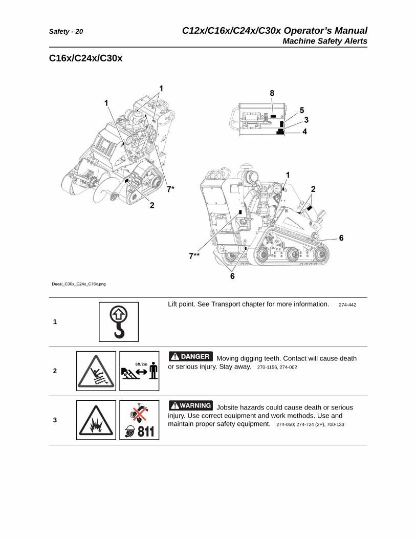
C16x/C24x/C30x
1
Lift point. See Transport chapter for more information. 274-442
2
Moving digging teeth. Contact will cause death or serious injury. Stay away. 270-1156, 274-002
3
Jobsite hazards could cause death or serious injury. Use correct equipment and work methods. Use and maintain proper safety equipment. 274-050; 274-724 (2P), 700-133
6ft/2m
C12x/C16x/C24x/C30x Operator’s Manual Safety - 21
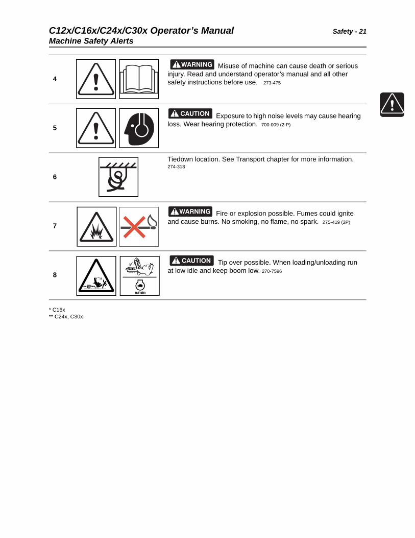
Machine Safety Alerts
* C16x** C24x, C30x
4
Misuse of machine can cause death or serious injury. Read and understand operator’s manual and all other safety instructions before use. 273-475
5
Exposure to high noise levels may cause hearing loss. Wear hearing protection. 700-009 (2-P)
6
Tiedown location. See Transport chapter for more information.274-318
7
Fire or explosion possible. Fumes could ignite and cause burns. No smoking, no flame, no spark. 275-419 (2P)
8
Tip over possible. When loading/unloading run at low idle and keep boom low. 270-7596
Safety - 22 C12x/C16x/C24x/C30x Operator’s ManualAttachment Safety Alerts
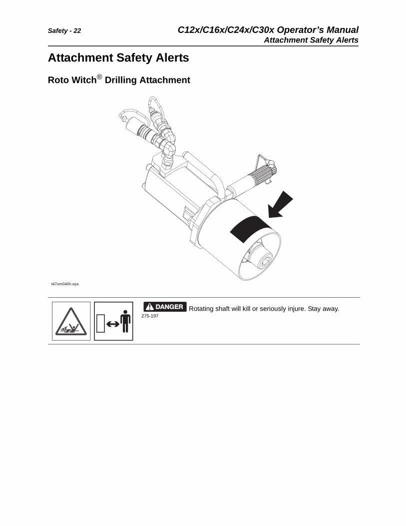
Attachment Safety Alerts
Roto Witch® Drilling Attachment
Rotating shaft will kill or seriously injure. Stay away. 275-197
C12x/C16x/C24x/C30x Operator’s Manual Controls - 23
Controls
Chapter Contents
Control Console . . . . . . . . . . . . . . . . . . . . . . . . . . . 24
C12x Engine Controls. . . . . . . . . . . . . . . . . . . . . . . 27
C16x Engine Controls. . . . . . . . . . . . . . . . . . . . . . . 27
C24x Engine Controls. . . . . . . . . . . . . . . . . . . . . . . 31
C30x Engine Controls. . . . . . . . . . . . . . . . . . . . . . . 33
Controls - 24 C12x/C16x/C24x/C30x Operator’s ManualControl Console
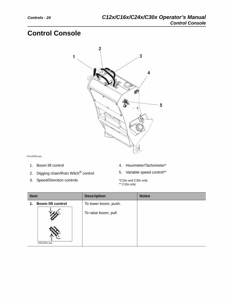
Control Console
1. Boom lift control
2. Digging chain/Roto Witch® control
3. Speed/Direction controls
4. Hourmeter/Tachometer*
5. Variable speed control**
*C16x and C30x only** C16x only
Item Description Notes
1. Boom lift control To lower boom, push.
To raise boom, pull.
C12x/C16x/C24x/C30x Operator’s Manual Controls - 25
Control Console
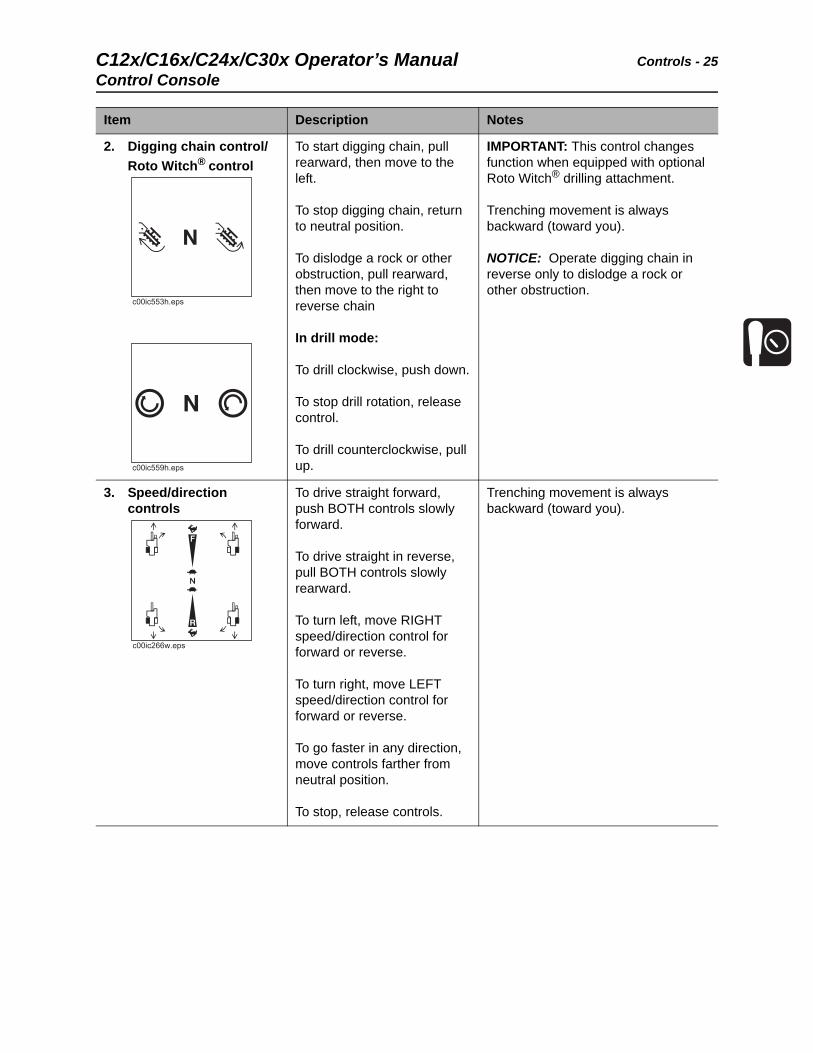
2. Digging chain control/
Roto Witch® control
To start digging chain, pull rearward, then move to the left.
To stop digging chain, return to neutral position.
To dislodge a rock or other obstruction, pull rearward, then move to the right to reverse chain
In drill mode:
To drill clockwise, push down.
To stop drill rotation, release control.
To drill counterclockwise, pull up.
IMPORTANT: This control changes function when equipped with optional Roto Witch® drilling attachment.
Trenching movement is always backward (toward you).
NOTICE: Operate digging chain in reverse only to dislodge a rock or other obstruction.
3. Speed/direction controls
To drive straight forward, push BOTH controls slowly forward.
To drive straight in reverse, pull BOTH controls slowly rearward.
To turn left, move RIGHT speed/direction control for forward or reverse.
To turn right, move LEFT speed/direction control for forward or reverse.
To go faster in any direction, move controls farther from neutral position.
To stop, release controls.
Trenching movement is always backward (toward you).
Item Description Notes
c00ic266w.eps
Controls - 26 C12x/C16x/C24x/C30x Operator’s ManualControl Console
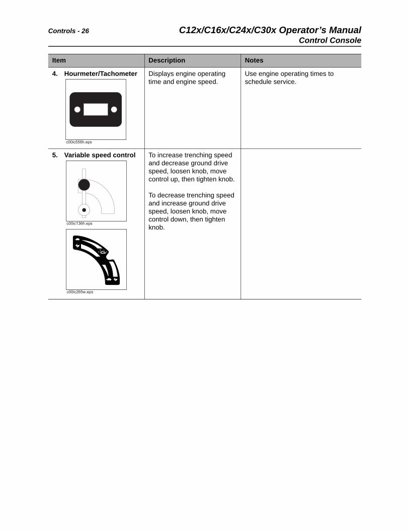
4. Hourmeter/Tachometer Displays engine operating time and engine speed.
Use engine operating times to schedule service.
5. Variable speed control To increase trenching speed and decrease ground drive speed, loosen knob, move control up, then tighten knob.
To decrease trenching speed and increase ground drive speed, loosen knob, move control down, then tighten knob.
Item Description Notes
c00ic265w.eps
C12x/C16x/C24x/C30x Operator’s Manual Controls - 27
C12x Engine Controls
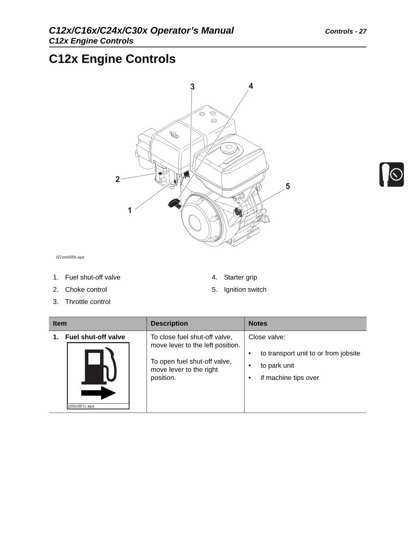
C12x Engine Controls
1. Fuel shut-off valve
2. Choke control
3. Throttle control
4. Starter grip
5. Ignition switch
Item Description Notes
1. Fuel shut-off valve To close fuel shut-off valve, move lever to the left position.
To open fuel shut-off valve, move lever to the right position.
Close valve:
• to transport unit to or from jobsite
• to park unit
• if machine tips over
Controls - 28 C12x/C16x/C24x/C30x Operator’s ManualC12x Engine Controls
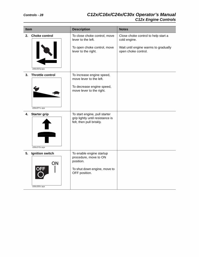
2. Choke control To close choke control, move lever to the left.
To open choke control, move lever to the right.
Close choke control to help start a cold engine.
Wait until engine warms to gradually open choke control.
3. Throttle control To increase engine speed, move lever to the left.
To decrease engine speed, move lever to the right.
4. Starter grip To start engine, pull starter grip lightly until resistance is felt, then pull briskly.
5. Ignition switch To enable engine startup procedure, move to ON position.
To shut down engine, move to OFF position.
Item Description Notes
C12x/C16x/C24x/C30x Operator’s Manual Controls - 29
C16x Engine Controls
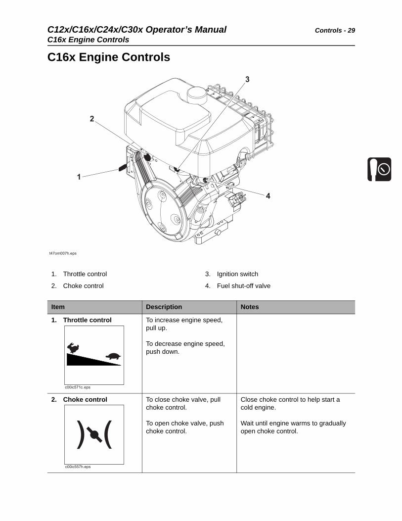
C16x Engine Controls
1. Throttle control
2. Choke control
3. Ignition switch
4. Fuel shut-off valve
Item Description Notes
1. Throttle control To increase engine speed, pull up.
To decrease engine speed, push down.
2. Choke control To close choke valve, pull choke control.
To open choke valve, push choke control.
Close choke control to help start a cold engine.
Wait until engine warms to gradually open choke control.
Controls - 30 C12x/C16x/C24x/C30x Operator’s ManualC16x Engine Controls
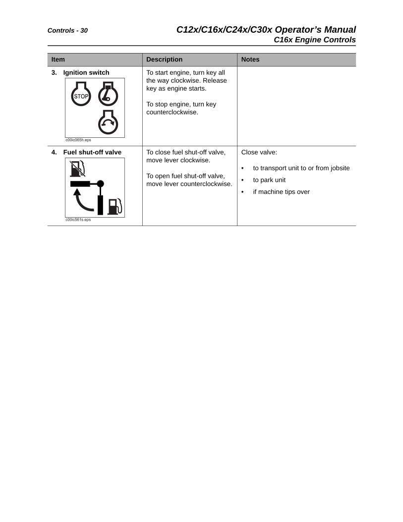
3. Ignition switch To start engine, turn key all the way clockwise. Release key as engine starts.
To stop engine, turn key counterclockwise.
4. Fuel shut-off valve To close fuel shut-off valve, move lever clockwise.
To open fuel shut-off valve, move lever counterclockwise.
Close valve:
• to transport unit to or from jobsite
• to park unit
• if machine tips over
Item Description Notes
C12x/C16x/C24x/C30x Operator’s Manual Controls - 31
C24x Engine Controls
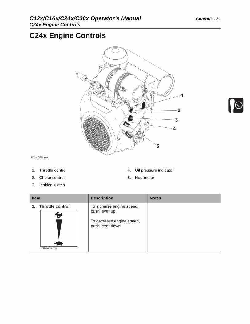
C24x Engine Controls
1. Throttle control
2. Choke control
3. Ignition switch
4. Oil pressure indicator
5. Hourmeter
Item Description Notes
1. Throttle control To increase engine speed, push lever up.
To decrease engine speed, push lever down.
Controls - 32 C12x/C16x/C24x/C30x Operator’s ManualC24x Engine Controls
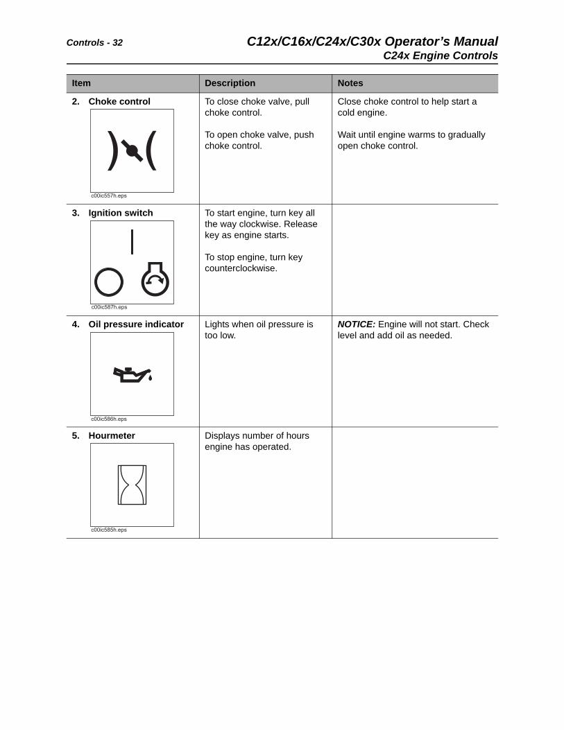
2. Choke control To close choke valve, pull choke control.
To open choke valve, push choke control.
Close choke control to help start a cold engine.
Wait until engine warms to gradually open choke control.
3. Ignition switch To start engine, turn key all the way clockwise. Release key as engine starts.
To stop engine, turn key counterclockwise.
4. Oil pressure indicator Lights when oil pressure is too low.
NOTICE: Engine will not start. Check level and add oil as needed.
5. Hourmeter Displays number of hours engine has operated.
Item Description Notes
C12x/C16x/C24x/C30x Operator’s Manual Controls - 33
C30x Engine Controls
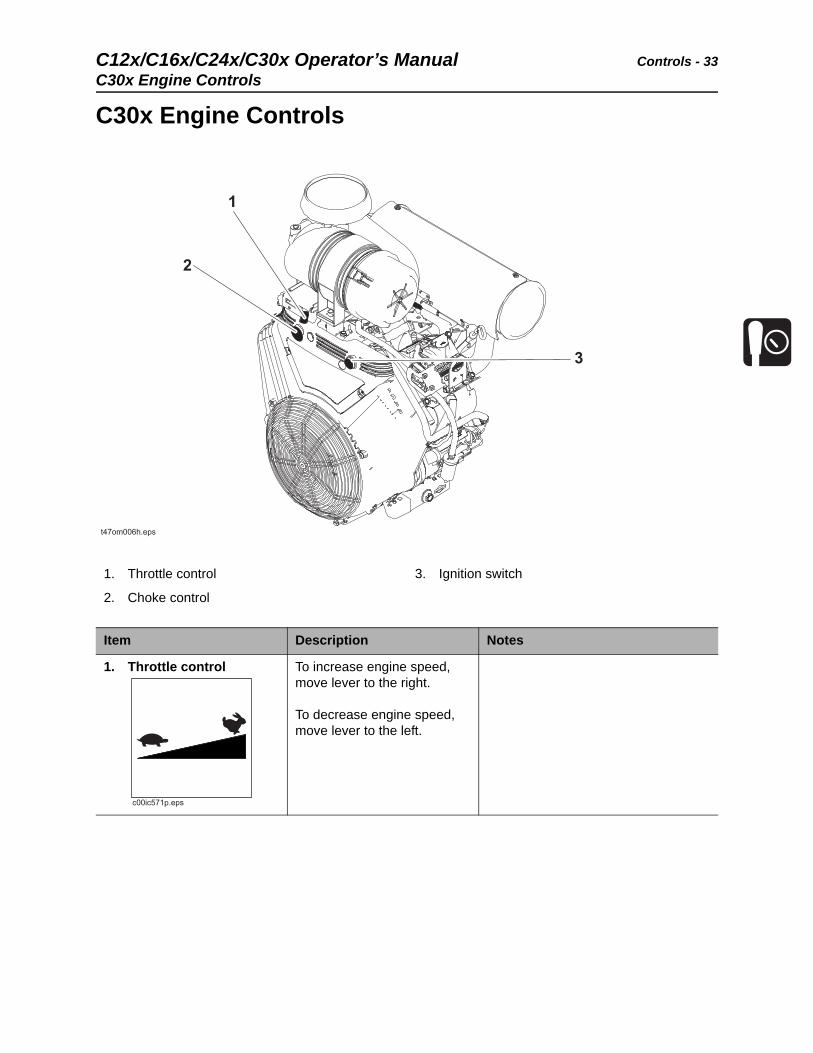
C30x Engine Controls
1. Throttle control
2. Choke control
3. Ignition switch
Item Description Notes
1. Throttle control To increase engine speed, move lever to the right.
To decrease engine speed, move lever to the left.
Controls - 34 C12x/C16x/C24x/C30x Operator’s ManualC30x Engine Controls
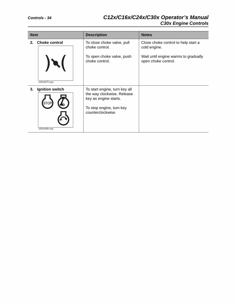
2. Choke control To close choke valve, pull choke control.
To open choke valve, push choke control.
Close choke control to help start a cold engine.
Wait until engine warms to gradually open choke control.
3. Ignition switch To start engine, turn key all the way clockwise. Release key as engine starts.
To stop engine, turn key counterclockwise.
Item Description Notes
C12x/C16x/C24x/C30x Operator’s Manual Operation Overview - 35
Operation Overview
Chapter Contents
Plan . . . . . . . . . . . . . . . . . . . . . . . . . . . . . . . . . . . . . 36
Trench . . . . . . . . . . . . . . . . . . . . . . . . . . . . . . . . . . . 36
Leave Jobsite . . . . . . . . . . . . . . . . . . . . . . . . . . . . . 36
Operation Overview - 36 C12x/C16x/C24x/C30x Operator’s ManualPlan
Plan
1. Gather information about jobsite. See page 38.
2. Inspect jobsite. See page 39.
3. Classify jobsite. See page 40.
4. Select best chain type and tooth pattern for your application. See page 80.
5. Consider optional equipment, if necessary. See page 82.
6. Check supplies and prepare equipment. See page 43.
7. Load unit onto trailer. See page 54.
Trench
1. Unload unit from trailer. See page 57.
2. Leave optional backfill blade, if equipped, in stowed position with digging boom low to ground. See page 83.
3. Start unit. See page 46.
4. Drive to starting point of trench. See page 47.
5. Dig the trench. See page 61.
6. Shut down unit. See page 49.
Leave Jobsite
1. Restore the jobsite. See page 88.
2. Rinse unit and stow tools. See page 88.
3. Load unit onto trailer. See page 54.
C12x/C16x/C24x/C30x Operator’s Manual Prepare - 37
Prepare
Chapter Contents
Gather Information . . . . . . . . . . . . . . . . . . . . . . . . . 38
• Review Job Plan . . . . . . . . . . . . . . . . . . . . . . . . . . . . . . . . . . . . . . . . . . .38
• Notify One-Call Services . . . . . . . . . . . . . . . . . . . . . . . . . . . . . . . . . . . . .38
• Arrange for Traffic Control. . . . . . . . . . . . . . . . . . . . . . . . . . . . . . . . . . . .38
• Plan for Emergency Services . . . . . . . . . . . . . . . . . . . . . . . . . . . . . . . . .38
Inspect Site . . . . . . . . . . . . . . . . . . . . . . . . . . . . . . . 39
• Identify Hazards . . . . . . . . . . . . . . . . . . . . . . . . . . . . . . . . . . . . . . . . . . .39
Classify Jobsite. . . . . . . . . . . . . . . . . . . . . . . . . . . . 40
• Select a Classification . . . . . . . . . . . . . . . . . . . . . . . . . . . . . . . . . . . . . . .40
• Apply Precautions . . . . . . . . . . . . . . . . . . . . . . . . . . . . . . . . . . . . . . . . . .41
Check Supplies and Prepare Equipment . . . . . . . 43
• Check Supplies . . . . . . . . . . . . . . . . . . . . . . . . . . . . . . . . . . . . . . . . . . . .43
• Prepare Equipment . . . . . . . . . . . . . . . . . . . . . . . . . . . . . . . . . . . . . . . . .43
• Assemble Accessories . . . . . . . . . . . . . . . . . . . . . . . . . . . . . . . . . . . . . .43
Prepare - 38 C12x/C16x/C24x/C30x Operator’s ManualGather Information
Gather Information
A successful job begins before the bore. The first step in planning is reviewing information already available about the job and jobsite.
Review Job Plan
Review blueprints or other plans. Check for information about existing or planned structures, elevations, or proposed work that may be taking place at the same time.
Notify One-Call Services
Mark proposed path with white paint and have underground utilities located before working.
• In the US or Canada, call 811 (US) or 888-258-0808 (US and Canada). Also contact any local utilities that do not participate in the One-Call service.
• In countries that do not have a One-Call service, contact all local utility companies to have underground utilities located.
Arrange for Traffic Control
If working near a road or other traffic area, contact local authorities about safety procedures and regulations.
Plan for Emergency Services
Have the telephone numbers for local emergency and medical facilities on hand. Check that you will have access to a telephone.
C12x/C16x/C24x/C30x Operator’s Manual Prepare - 39
Inspect Site
Inspect Site
Identify Hazards
Inspect jobsite before transporting equipment. Check for the following:
• overall grade or slope
• changes in elevation such as hills or open trenches
• obstacles such as buildings, railroad crossings, or streams
• signs of utilities on jobsite and perimeter, such as:
– “buried utility” notices
– utility facilities without overhead lines
– gas or water meters
– junction boxes
– drop boxes
– light poles
– manhole covers
– sunken ground
• traffic
• access
• soil type and condition
• water supply
• sources of locator interference (rebar, railroad tracks, etc.)
Have an experienced locating equipment operator sweep area within 20’ (6 m) to each side of trench path to verify previously marked line and cable locations. Mark location of all buried utilities and obstructions.
Prepare - 40 C12x/C16x/C24x/C30x Operator’s ManualClassify Jobsite
Classify Jobsite
Select a Classification
Jobsites are classified according to underground hazards present.
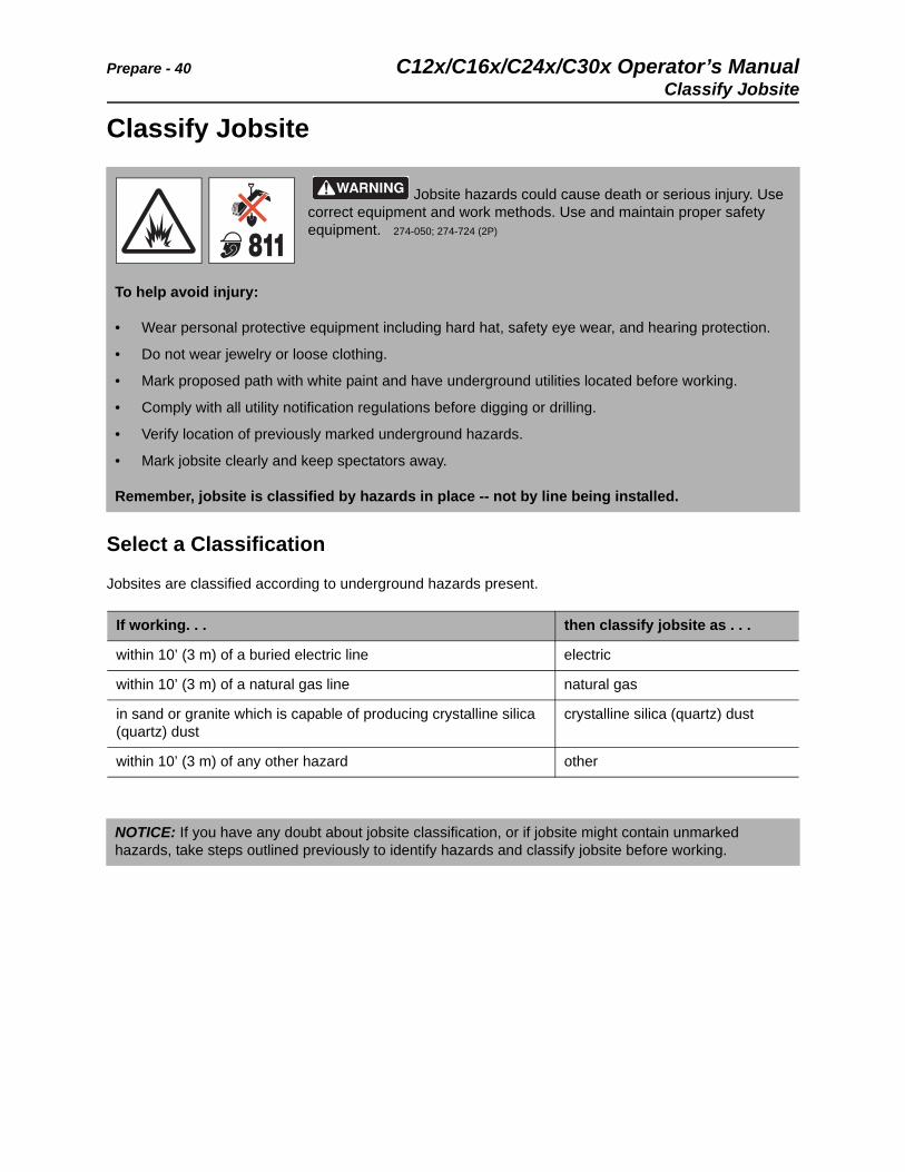
Jobsite hazards could cause death or serious injury. Use correct equipment and work methods. Use and maintain proper safety equipment. 274-050; 274-724 (2P)
To help avoid injury:
• Wear personal protective equipment including hard hat, safety eye wear, and hearing protection.
• Do not wear jewelry or loose clothing.
• Mark proposed path with white paint and have underground utilities located before working.
• Comply with all utility notification regulations before digging or drilling.
• Verify location of previously marked underground hazards.
• Mark jobsite clearly and keep spectators away.
Remember, jobsite is classified by hazards in place -- not by line being installed.
If working. . . then classify jobsite as . . .
within 10’ (3 m) of a buried electric line electric
within 10’ (3 m) of a natural gas line natural gas
in sand or granite which is capable of producing crystalline silica (quartz) dust
crystalline silica (quartz) dust
within 10’ (3 m) of any other hazard other
NOTICE: If you have any doubt about jobsite classification, or if jobsite might contain unmarked hazards, take steps outlined previously to identify hazards and classify jobsite before working.
C12x/C16x/C24x/C30x Operator’s Manual Prepare - 41
Classify Jobsite
Apply Precautions
Once classified, precautions appropriate for jobsite must be taken. Follow U.S. Department of Labor regulations on excavating and trenching (Part 1926, Subpart P) and other similar regulations.
Electric Jobsite Precautions
Use one or both of these methods.
• Expose line by careful hand digging or soft excavation.
• Have service shut down while work is in progress. Have electric company test lines before returning them to service.
Natural Gas Jobsite Precautions
In addition to positioning equipment upwind from gas lines, use one or both of these methods.
• Expose lines by careful hand digging or soft excavation.
• Have gas shut off while work is in progress. Have gas company test lines before returning them to service.
Electric shock will cause death or serious injury. Stay away. 274-049
Prepare - 42 C12x/C16x/C24x/C30x Operator’s ManualClassify Jobsite
Crystalline Silica (Quartz) Dust Precautions
Crystalline silica dust is a naturally occurring substance found in soil, sand, concrete, granite, and quartz. Breathing silica dust particles while cutting, drilling, or working materials may cause lung disease or cancer. To reduce exposure:
• Use water spray or other means to control dust.
• Refer to U.S. Department of Labor Occupational Safety and Health Administration guidelines to learn more about appropriate breathing protection and permissible exposure limits.
Other Jobsite Precautions
You may need to use different methods to safely avoid other underground hazards. Talk with those knowledgeable about hazards present at each site to determine which precautions should be taken or if job should be attempted.
Breathing crystalline silica dust may cause lung disease. Cutting, drilling, or working materials such as concrete, sand, or rock containing quartz may result in exposure to silica dust. Use dust control methods or appropriate breathing protection when exposed to silica dust.
To help avoid injury:
• Use water spray or other means to control dust.
• Refer to U.S. Department of Labor Occupational Safety and Health Administration guidelines to learn more about appropriate breathing protection and permissible exposure limits.
C12x/C16x/C24x/C30x Operator’s Manual Prepare - 43
Check Supplies and Prepare Equipment
Check Supplies and Prepare Equipment
Check Supplies
• fuel
• keys
• personal protective equipment, such as hard hat and safety glasses
Prepare Equipment
Fluid Levels
• fuel
• hydraulic fluid
• battery charge
• engine oil
Condition and Function
• all controls
• digging chain and teeth
• filters (air, oil, hydraulic, and fuel if equipped)
• tracks
• pumps and motors
• hoses and valves
• signs, guards, and shields
Assemble Accessories
Fire Extinguisher
If required, mount a fire extinguisher near the power unit but away from possible points of ignition. The fire extinguisher should always be classified for both oil and electric fires. It should meet legal and regulatory requirements.
Improper control function could cause death or serious injury. If control does not work as described in instructions, stop machine and have it serviced.

Prepare - 44 C12x/C16x/C24x/C30x Operator’s ManualCheck Supplies and Prepare Equipment
C12x/C16x/C24x/C30x Operator’s Manual Drive - 45
Drive
Chapter Contents
Start Unit . . . . . . . . . . . . . . . . . . . . . . . . . . . . . . . . . 46
Drive . . . . . . . . . . . . . . . . . . . . . . . . . . . . . . . . . . . . . 47
• General Operation. . . . . . . . . . . . . . . . . . . . . . . . . . . . . . . . . . . . . . . . . .47
• Safe Slope Operation . . . . . . . . . . . . . . . . . . . . . . . . . . . . . . . . . . . . . . .48
Shut Down . . . . . . . . . . . . . . . . . . . . . . . . . . . . . . . . 49
Drive - 46 C12x/C16x/C24x/C30x Operator’s ManualStart Unit
Start Unit
Before operating pedestrian unit, read engine manufacturer’s starting and operating instructions.
1. Clear the area around the machine of all bystanders.
2. Ensure all controls are in neutral.
3. If necessary, use choke control to help start cold engine.
4. Start engine.
• C12x: Turn ignition switch clockwise. Pull starter grip lightly until resistance is felt, then pull briskly to start engine.
• C16x/C24x/C30x: Turn ignition switch clockwise to start engine.
5. Move throttle to 1/4 open.
6. Run engine at half throttle or less for five minutes before operating trencher. During warm-up, ensure all controls function properly.
Misuse of machine can cause death or serious injury. Read and understand operator’s manual and all other safety instructions before use.
To help avoid injury: Wear hard hat, safety glasses, and other protective equipment required by job. Do not wear jewelry or loose clothing that can catch on controls.
Fire or explosion possible. Do not use starter fluid.
C12x/C16x/C24x/C30x Operator’s Manual Drive - 47
Drive
Drive
General Operation
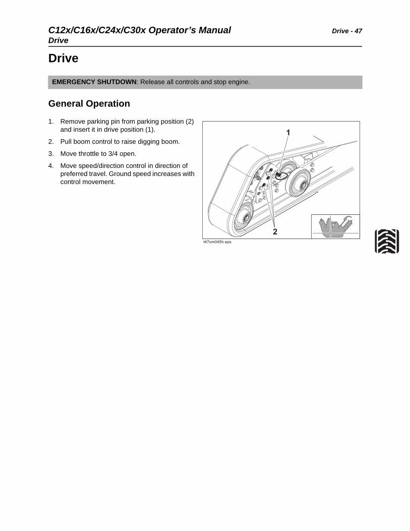
1. Remove parking pin from parking position (2) and insert it in drive position (1).
2. Pull boom control to raise digging boom.
3. Move throttle to 3/4 open.
4. Move speed/direction control in direction of preferred travel. Ground speed increases with control movement.
EMERGENCY SHUTDOWN: Release all controls and stop engine.
Drive - 48 C12x/C16x/C24x/C30x Operator’s ManualDrive
Safe Slope Operation
Operating safely on a slope depends upon many factors including:
• Distribution of machine weight (weight of machine may change due to configuration)
• Even or rough ground conditions
• Potential for ground giving way causing unplanned tilt forward, reverse or sideways
• Nearness of ditches, ruts, stumps or other obstructions and sudden changes in slope
• Speed
• Turning
• Operator skill
These varying factors make it impractical to specify a maximum safe operating angle in this manual. It is therefore important for the operator to be aware of these conditions and adjust operation accordingly. Maximum engine angle is an absolute limit which must never be exceeded. This maximum is stated below since it is a design limit. This design limit usually exceeds the operating limit and must never be used alone to establish safe operating angle for variable conditions.
Maximum engine lubrication angle – 20°
Tipover possible. Machine can tip over and crush you.
To help avoid injury:
• Always operate from uphill side of machine.
• Keep digging boom low.
• Drive cautiously at all times.
• Do not drive across slopes.
• Never jerk control levers. Use a steady even motion.
• Do not park unit on a slope without lowering digging attachment to the ground, returning all controls to neutral position, shutting down unit, chocking or blocking tracks, and securing parking pin.
If the machine tips over, there is a risk of fuel leakage.Fire or explosion can cause death or serious injuries.
To help avoid injury: If the machine tips over, turn ignition switch to OFF position or close the fuel shutoff valve, if equipped.
C12x/C16x/C24x/C30x Operator’s Manual Drive - 49
Shut Down
Shut Down
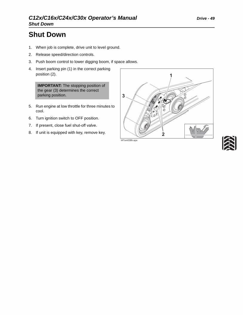
1. When job is complete, drive unit to level ground.
2. Release speed/direction controls.
3. Push boom control to lower digging boom, if space allows.
4. Insert parking pin (1) in the correct parking position (2).
5. Run engine at low throttle for three minutes to cool.
6. Turn ignition switch to OFF position.
7. If present, close fuel shut-off valve.
8. If unit is equipped with key, remove key.
IMPORTANT: The stopping position of the gear (3) determines the correct parking position.

Drive - 50 C12x/C16x/C24x/C30x Operator’s ManualShut Down
C12x/C16x/C24x/C30x Operator’s Manual Transport - 51
Transport
Chapter Contents
Lift . . . . . . . . . . . . . . . . . . . . . . . . . . . . . . . . . . . . . . 52
• Points . . . . . . . . . . . . . . . . . . . . . . . . . . . . . . . . . . . . . . . . . . . . . . . . . . .52
• Procedure . . . . . . . . . . . . . . . . . . . . . . . . . . . . . . . . . . . . . . . . . . . . . . . .53
Haul . . . . . . . . . . . . . . . . . . . . . . . . . . . . . . . . . . . . . 54
• Load . . . . . . . . . . . . . . . . . . . . . . . . . . . . . . . . . . . . . . . . . . . . . . . . . . . .54
• Tie down . . . . . . . . . . . . . . . . . . . . . . . . . . . . . . . . . . . . . . . . . . . . . . . . .55
• Unload. . . . . . . . . . . . . . . . . . . . . . . . . . . . . . . . . . . . . . . . . . . . . . . . . . .57
Retrieve . . . . . . . . . . . . . . . . . . . . . . . . . . . . . . . . . . 58
Transport - 52 C12x/C16x/C24x/C30x Operator’s ManualLift
Lift
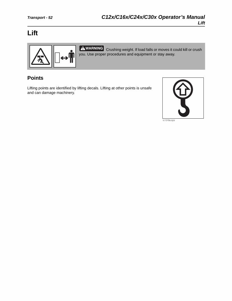
Points
Lifting points are identified by lifting decals. Lifting at other points is unsafe and can damage machinery.
Crushing weight. If load falls or moves it could kill or crush you. Use proper procedures and equipment or stay away.
C12x/C16x/C24x/C30x Operator’s Manual Transport - 53
Lift
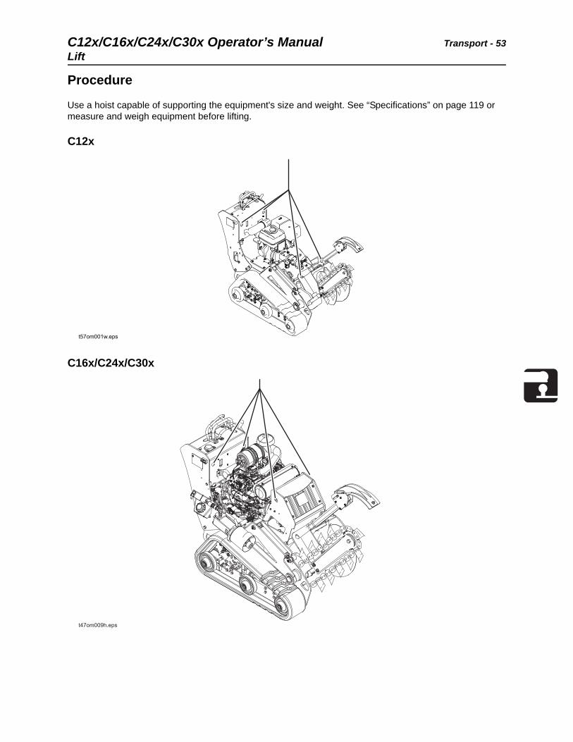
Procedure
Use a hoist capable of supporting the equipment's size and weight. See “Specifications” on page 119 or measure and weigh equipment before lifting.
C12x
C16x/C24x/C30x
t57om001w.eps
Transport - 54 C12x/C16x/C24x/C30x Operator’s ManualHaul
Haul
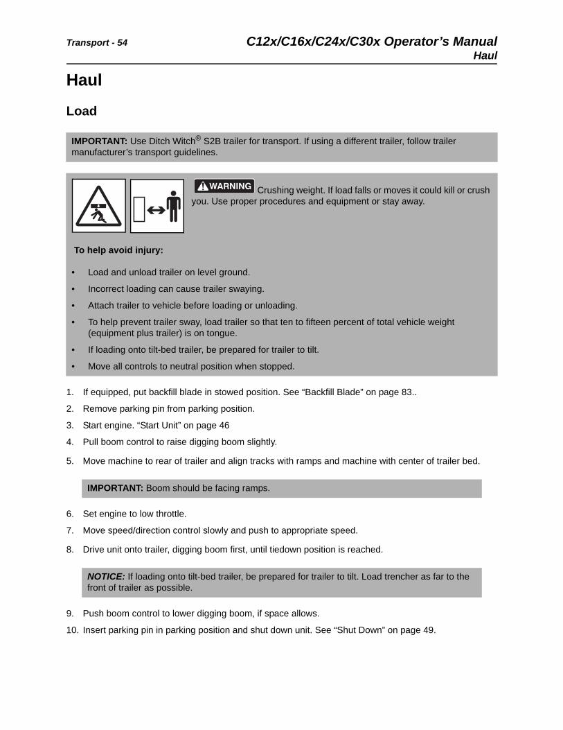
Load
1. If equipped, put backfill blade in stowed position. See “Backfill Blade” on page 83..
2. Remove parking pin from parking position.
3. Start engine. “Start Unit” on page 46
4. Pull boom control to raise digging boom slightly.
5. Move machine to rear of trailer and align tracks with ramps and machine with center of trailer bed.
6. Set engine to low throttle.
7. Move speed/direction control slowly and push to appropriate speed.
8. Drive unit onto trailer, digging boom first, until tiedown position is reached.
9. Push boom control to lower digging boom, if space allows.
10. Insert parking pin in parking position and shut down unit. See “Shut Down” on page 49.
IMPORTANT: Use Ditch Witch® S2B trailer for transport. If using a different trailer, follow trailer manufacturer’s transport guidelines.
Crushing weight. If load falls or moves it could kill or crush you. Use proper procedures and equipment or stay away.
To help avoid injury:
• Load and unload trailer on level ground.
• Incorrect loading can cause trailer swaying.
• Attach trailer to vehicle before loading or unloading.
• To help prevent trailer sway, load trailer so that ten to fifteen percent of total vehicle weight (equipment plus trailer) is on tongue.
• If loading onto tilt-bed trailer, be prepared for trailer to tilt.
• Move all controls to neutral position when stopped.
IMPORTANT: Boom should be facing ramps.
NOTICE: If loading onto tilt-bed trailer, be prepared for trailer to tilt. Load trencher as far to the front of trailer as possible.
C12x/C16x/C24x/C30x Operator’s Manual Transport - 55
Haul
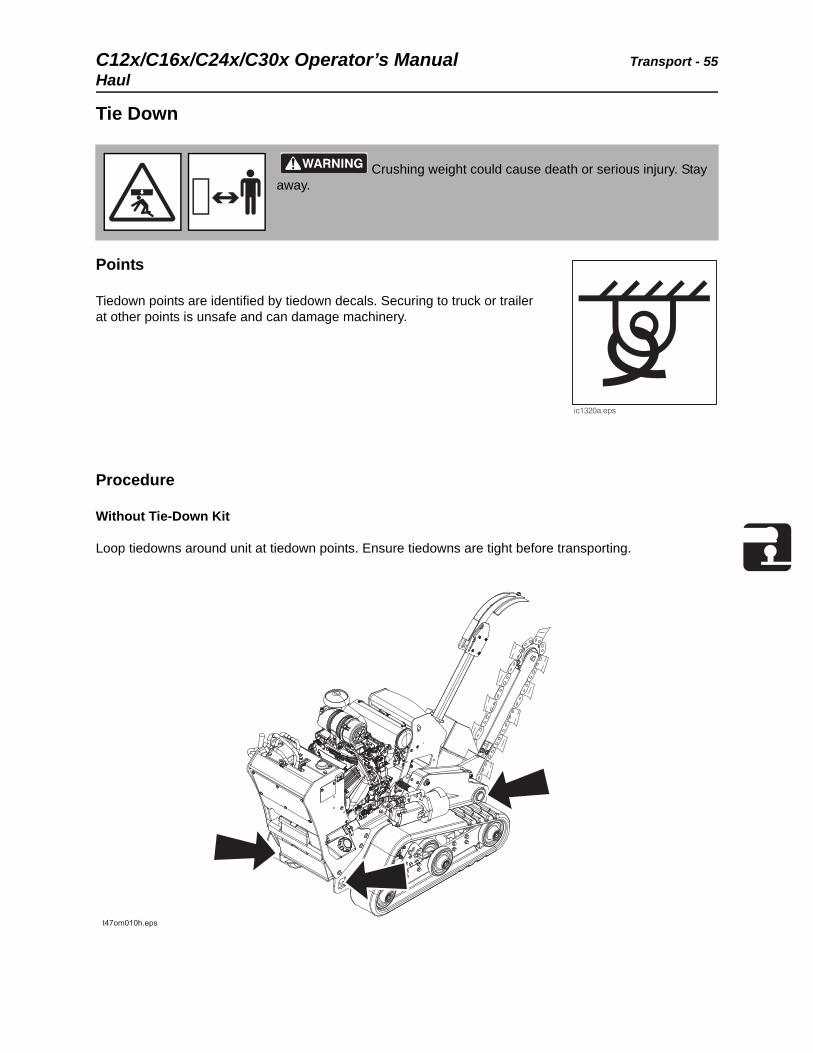
Tie Down
Points
Tiedown points are identified by tiedown decals. Securing to truck or trailer at other points is unsafe and can damage machinery.
Procedure
Without Tie-Down Kit
Loop tiedowns around unit at tiedown points. Ensure tiedowns are tight before transporting.
Crushing weight could cause death or serious injury. Stay away.
Transport - 56 C12x/C16x/C24x/C30x Operator’s ManualHaul
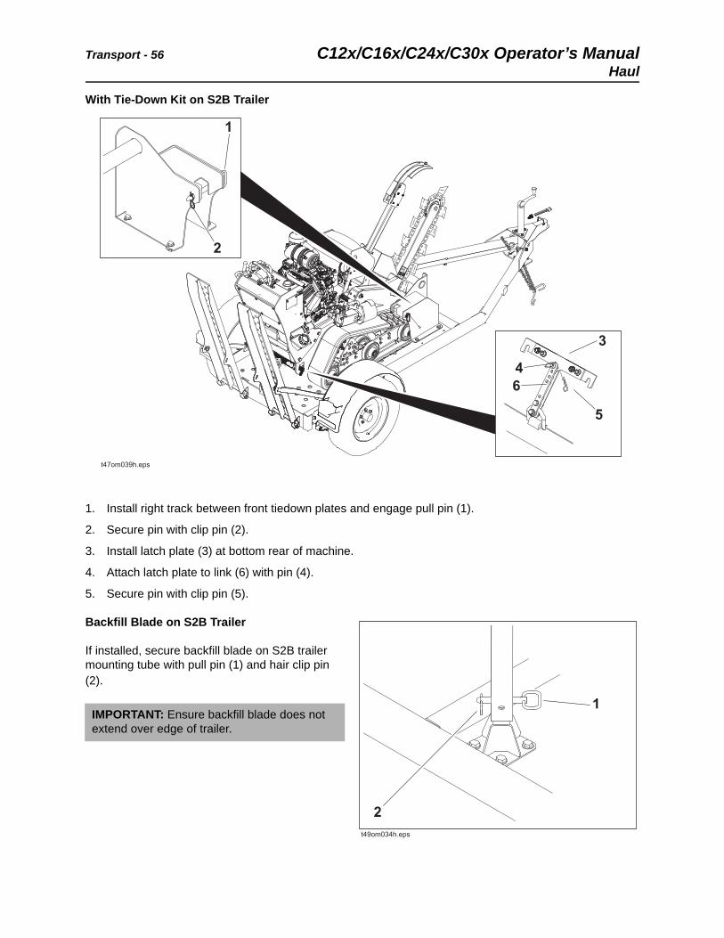
With Tie-Down Kit on S2B Trailer
1. Install right track between front tiedown plates and engage pull pin (1).
2. Secure pin with clip pin (2).
3. Install latch plate (3) at bottom rear of machine.
4. Attach latch plate to link (6) with pin (4).
5. Secure pin with clip pin (5).
Backfill Blade on S2B Trailer
If installed, secure backfill blade on S2B trailer mounting tube with pull pin (1) and hair clip pin (2).
IMPORTANT: Ensure backfill blade does not extend over edge of trailer.
22
11
66
44
33
55
t47om039h.epst47om039h.eps
C12x/C16x/C24x/C30x Operator’s Manual Transport - 57
Haul
Unload
1. Lower trailer or ramps.
2. Remove tiedowns.
3. If present, open fuel shut-off valve.
4. Remove parking pin from parking position.
5. Start engine. See “Start Unit” on page 46.
6. Set to low throttle.
7. Pull boom control to raise digging boom slightly.
8. Slowly back unit down trailer or ramps.
Crushing weight. If load falls or moves it could kill or crush you. Use proper procedures and equipment or stay away.
To help avoid injury:
• Unload unit with engine in low idle and boom as low as possible.
• Unload trailer on level ground.
• Attach trailer to vehicle before loading or unloading.
• If trailer tilts, ensure that tilt latch is secured in the correct position.
• Clear the area around the machine of all bystanders.
NOTICE: If unloading from tilt-bed trailer, be prepared for trailer to tilt.
Transport - 58 C12x/C16x/C24x/C30x Operator’s ManualRetrieve
Retrieve
Under normal conditions, pedestrian trencher should not be towed. If unit becomes disabled and retrieval is necessary:
• tow for no more than 200 yd (180 m) at less than 1 mph (1.6 km/h),
• use towing chains appropriately rated for maximum towing force,
• attach tow line to all available tie-down points facing towing vehicle,
• steering will be difficult.
Misuse of machine can cause death or serious injury. Read and understand operator’s manual and all other safety instructions before use.
C12x/C16x/C24x/C30x Operator’s Manual Trench - 59
Trench
Chapter Contents
Set Up. . . . . . . . . . . . . . . . . . . . . . . . . . . . . . . . . . . . 60
Operate . . . . . . . . . . . . . . . . . . . . . . . . . . . . . . . . . . 61
Finish Job . . . . . . . . . . . . . . . . . . . . . . . . . . . . . . . . 63
Trench - 60 C12x/C16x/C24x/C30x Operator’s ManualSet Up
Set Up
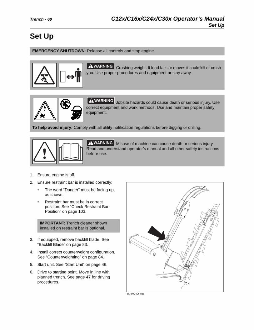
1. Ensure engine is off.
2. Ensure restraint bar is installed correctly:
• The word “Danger” must be facing up, as shown.
• Restraint bar must be in correct position. See “Check Restraint Bar Position” on page 103.
3. If equipped, remove backfill blade. See “Backfill Blade” on page 83.
4. Install correct counterweight configuration. See “Counterweighting” on page 84.
5. Start unit. See “Start Unit” on page 46.
6. Drive to starting point. Move in line with planned trench. See page 47 for driving procedures.
EMERGENCY SHUTDOWN: Release all controls and stop engine.
Crushing weight. If load falls or moves it could kill or crush you. Use proper procedures and equipment or stay away.
Jobsite hazards could cause death or serious injury. Use correct equipment and work methods. Use and maintain proper safety equipment.
To help avoid injury: Comply with all utility notification regulations before digging or drilling.
Misuse of machine can cause death or serious injury. Read and understand operator’s manual and all other safety instructions before use.
IMPORTANT: Trench cleaner shown installed on restraint bar is optional.
C12x/C16x/C24x/C30x Operator’s Manual Trench - 61
Operate
Operate
1. Move throttle to 1/2 open.
2. Push boom control to lower digging boom to just above ground.
Breathing crystalline silica dust may cause lung disease. Cutting, drilling, or working with materials such as concrete, sand, or rock containing quartz may result in exposure to silica dust. Use dust control methods or appropriate breathing protection when exposed to silica dust.
To help avoid injury:
• Use water spray or other means to control dust.
• Refer to U.S. Department of Labor Occupational Safety and Health Administration guidelines to learn more about appropriate breathing protection and permissible exposure limits.
Electric shock will cause death or serious injury. Stay away.
To help avoid injury: Expose lines by hand before digging. Cutting high voltage cable can cause electrocution.
Misuse of machine can cause death or serious injury. Read and understand operator’s manual and all other safety instructions before use.
Flying objects thrown by machine may strike people. Wear hard hat and safety glasses.
Trench - 62 C12x/C16x/C24x/C30x Operator’s ManualOperate
3. Move digging chain control to dig position. DIGGING CHAIN WILL MOVE.
4. Set throttle to full engine speed.
5. Slowly lower digging boom to desired trench depth.
6. If using trench cleaner,
• Move backward about 1’ (30 cm), or until there is enough room for trench cleaner to enter trench.
• Return control to neutral to stop forward movement.
• Raise boom slightly, then fully lower trench cleaner to lock it into place.
• Lower boom to desired trench depth.
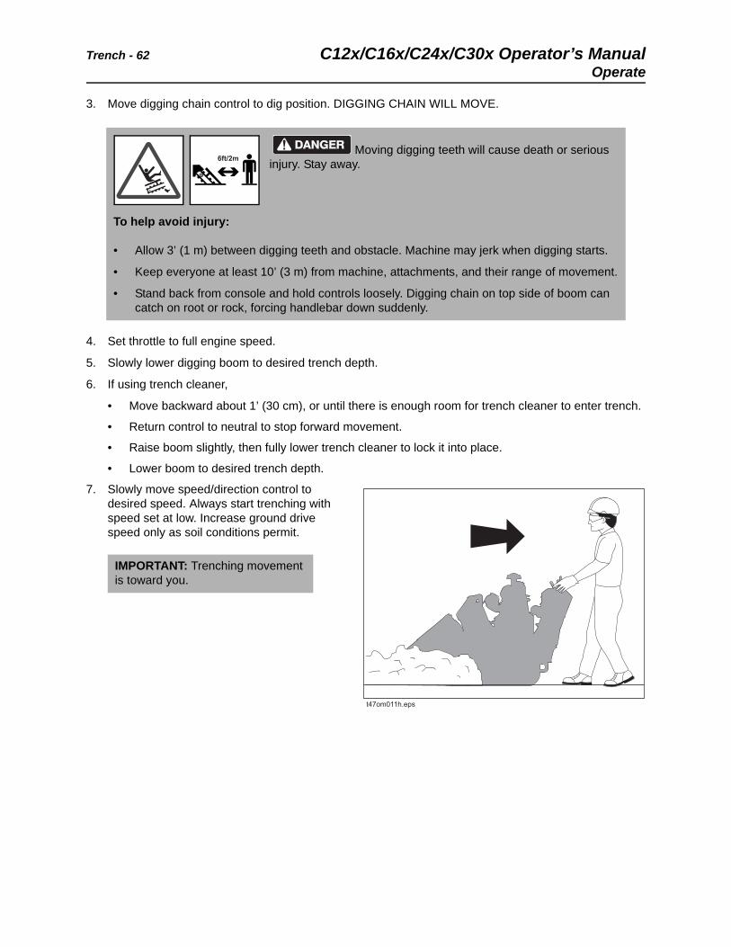
7. Slowly move speed/direction control to desired speed. Always start trenching with speed set at low. Increase ground drive speed only as soil conditions permit.
Moving digging teeth will cause death or serious injury. Stay away.
To help avoid injury:
• Allow 3’ (1 m) between digging teeth and obstacle. Machine may jerk when digging starts.
• Keep everyone at least 10’ (3 m) from machine, attachments, and their range of movement.
• Stand back from console and hold controls loosely. Digging chain on top side of boom can catch on root or rock, forcing handlebar down suddenly.
IMPORTANT: Trenching movement is toward you.
6ft/2m
C12x/C16x/C24x/C30x Operator’s Manual Trench - 63
Finish Job
8. Operate engine at full throttle when working.
Finish Job
1. When trench is complete, release speed/direction controls.
2. Move throttle to 1/2 open.
3. Raise boom.
4. Release digging chain control.
5. Raise trench cleaner, if equipped.
6. Install backfill blade and backfill, if desired.
7. Drive a short distance away from work site. See page 47 for driving procedures.
8. Shut down machine. See “Shut Down” page 47.
9. Stow trench cleaner, if needed.
NOTICE:
• Do not make sharp turns. Lower boom to full depth when turning.
• If an object becomes lodged in chain, release speed/direction controls, move digging chain control to neutral, and raise boom slightly. Reverse chain direction. If an object must be removed manually, turn engine off and insert parking pin.

Trench - 64 C12x/C16x/C24x/C30x Operator’s ManualFinish Job
C12x/C16x/C24x/C30x Operator’s Manual Drill - 65
Drill
Chapter Contents
Set Up. . . . . . . . . . . . . . . . . . . . . . . . . . . . . . . . . . . . 66
• Dig Approach Trench . . . . . . . . . . . . . . . . . . . . . . . . . . . . . . . . . . . . . . .66
• Dig Target Trench . . . . . . . . . . . . . . . . . . . . . . . . . . . . . . . . . . . . . . . . . .67
• Install Drill String . . . . . . . . . . . . . . . . . . . . . . . . . . . . . . . . . . . . . . . . . . .67
• Install Drilling Attachment . . . . . . . . . . . . . . . . . . . . . . . . . . . . . . . . . . . .68
• Connect Hydraulic Lines . . . . . . . . . . . . . . . . . . . . . . . . . . . . . . . . . . . . .68
Operate . . . . . . . . . . . . . . . . . . . . . . . . . . . . . . . . . . 69
• Drill . . . . . . . . . . . . . . . . . . . . . . . . . . . . . . . . . . . . . . . . . . . . . . . . . . . . .70
• Start Bore with Drill String Guide. . . . . . . . . . . . . . . . . . . . . . . . . . . . . . .71
• Add Rod . . . . . . . . . . . . . . . . . . . . . . . . . . . . . . . . . . . . . . . . . . . . . . . . .72
• Backream . . . . . . . . . . . . . . . . . . . . . . . . . . . . . . . . . . . . . . . . . . . . . . . .73
• Install Product . . . . . . . . . . . . . . . . . . . . . . . . . . . . . . . . . . . . . . . . . . . . .74
• Remove Rod . . . . . . . . . . . . . . . . . . . . . . . . . . . . . . . . . . . . . . . . . . . . . .75
Finish Job . . . . . . . . . . . . . . . . . . . . . . . . . . . . . . . . 77
• Disassemble Drill String . . . . . . . . . . . . . . . . . . . . . . . . . . . . . . . . . . . . .77
• Remove Drilling Attachment . . . . . . . . . . . . . . . . . . . . . . . . . . . . . . . . . .77
Drill - 66 C12x/C16x/C24x/C30x Operator’s ManualSet Up
Set Up
Dig Approach Trench
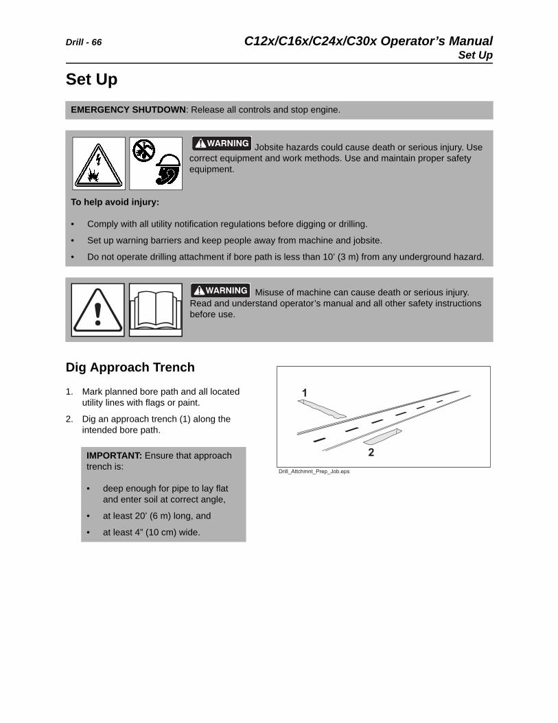
1. Mark planned bore path and all located utility lines with flags or paint.
2. Dig an approach trench (1) along the intended bore path.
EMERGENCY SHUTDOWN: Release all controls and stop engine.
Jobsite hazards could cause death or serious injury. Use correct equipment and work methods. Use and maintain proper safety equipment.
To help avoid injury:
• Comply with all utility notification regulations before digging or drilling.
• Set up warning barriers and keep people away from machine and jobsite.
• Do not operate drilling attachment if bore path is less than 10’ (3 m) from any underground hazard.
Misuse of machine can cause death or serious injury. Read and understand operator’s manual and all other safety instructions before use.
IMPORTANT: Ensure that approach trench is:
• deep enough for pipe to lay flat and enter soil at correct angle,
• at least 20’ (6 m) long, and
• at least 4” (10 cm) wide.
C12x/C16x/C24x/C30x Operator’s Manual Drill - 67
Set Up
Dig Target Trench
1. Select a completion point for the bore.
2. Dig a target trench (2) across the intended completion point.
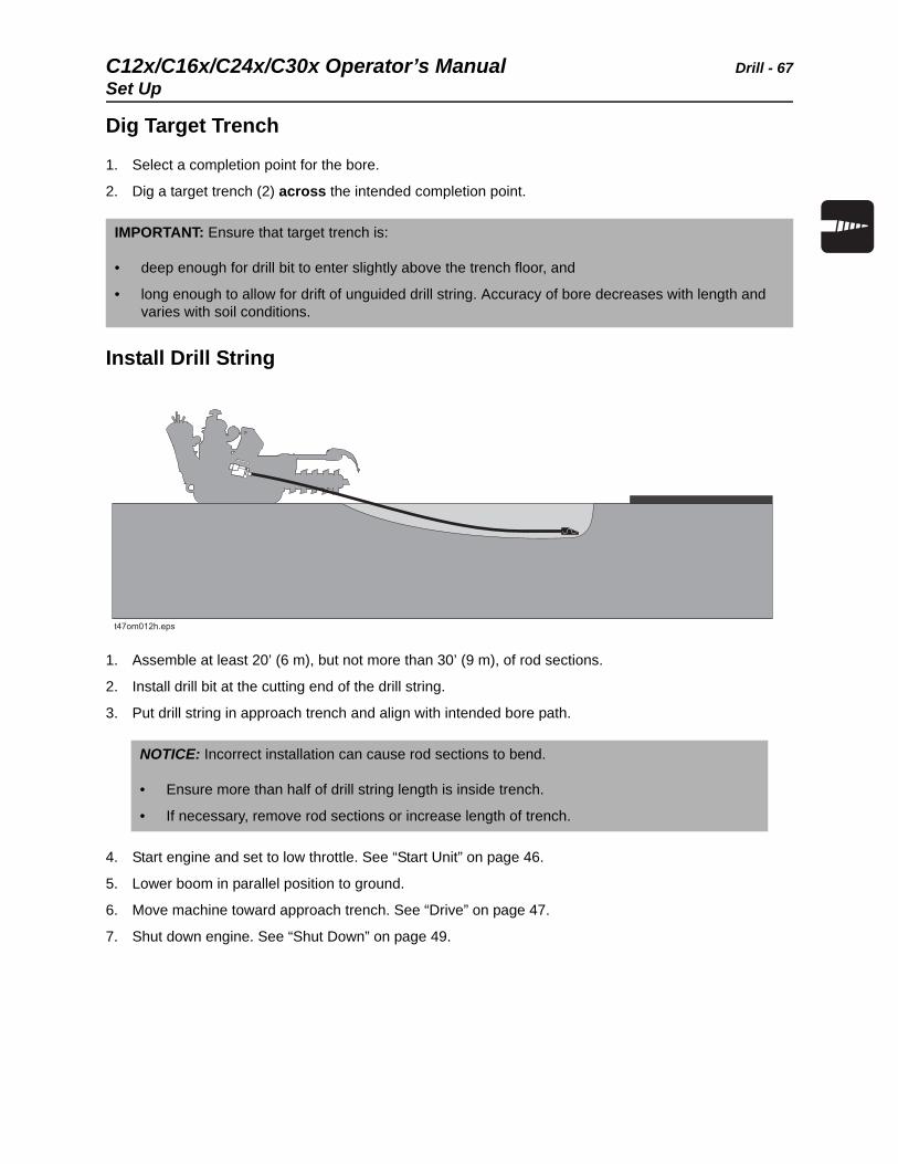
Install Drill String
1. Assemble at least 20’ (6 m), but not more than 30’ (9 m), of rod sections.
2. Install drill bit at the cutting end of the drill string.
3. Put drill string in approach trench and align with intended bore path.
4. Start engine and set to low throttle. See “Start Unit” on page 46.
5. Lower boom in parallel position to ground.
6. Move machine toward approach trench. See “Drive” on page 47.
7. Shut down engine. See “Shut Down” on page 49.
IMPORTANT: Ensure that target trench is:
• deep enough for drill bit to enter slightly above the trench floor, and
• long enough to allow for drift of unguided drill string. Accuracy of bore decreases with length and varies with soil conditions.
NOTICE: Incorrect installation can cause rod sections to bend.
• Ensure more than half of drill string length is inside trench.
• If necessary, remove rod sections or increase length of trench.
Drill - 68 C12x/C16x/C24x/C30x Operator’s ManualSet Up
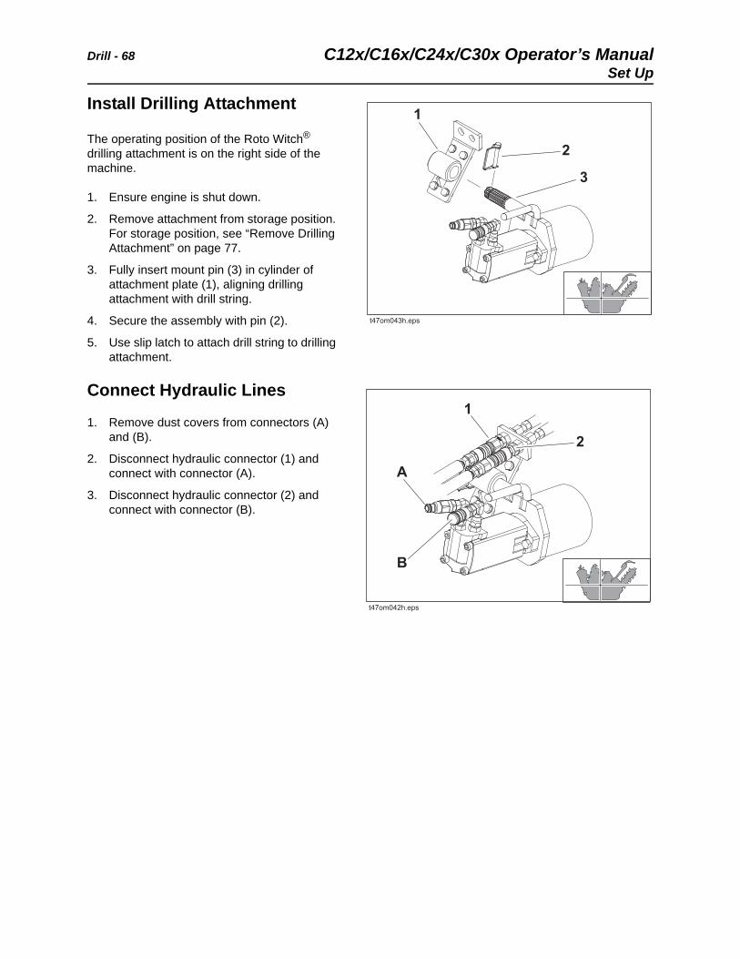
Install Drilling Attachment
The operating position of the Roto Witch® drilling attachment is on the right side of the machine.
1. Ensure engine is shut down.
2. Remove attachment from storage position. For storage position, see “Remove Drilling Attachment” on page 77.
3. Fully insert mount pin (3) in cylinder of attachment plate (1), aligning drilling attachment with drill string.
4. Secure the assembly with pin (2).
5. Use slip latch to attach drill string to drilling attachment.
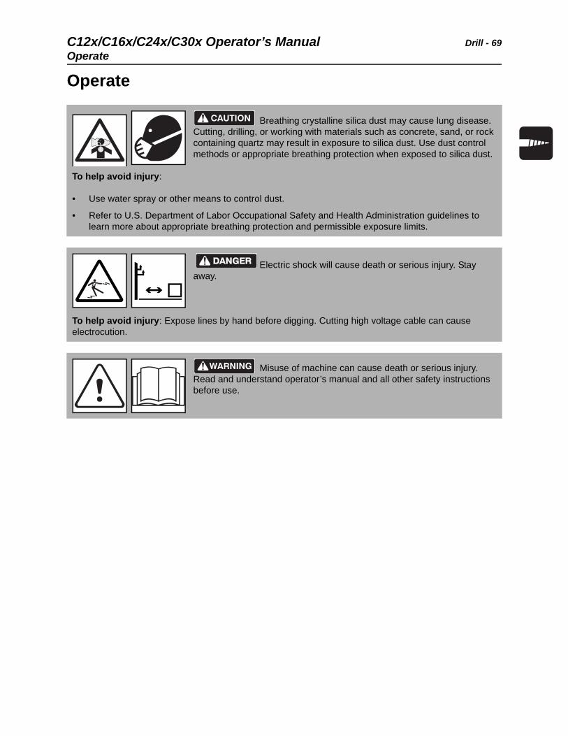
Connect Hydraulic Lines
1. Remove dust covers from connectors (A) and (B).
2. Disconnect hydraulic connector (1) and connect with connector (A).
3. Disconnect hydraulic connector (2) and connect with connector (B).
C12x/C16x/C24x/C30x Operator’s Manual Drill - 69
Operate
Operate
Breathing crystalline silica dust may cause lung disease. Cutting, drilling, or working with materials such as concrete, sand, or rock containing quartz may result in exposure to silica dust. Use dust control methods or appropriate breathing protection when exposed to silica dust.
To help avoid injury:
• Use water spray or other means to control dust.
• Refer to U.S. Department of Labor Occupational Safety and Health Administration guidelines to learn more about appropriate breathing protection and permissible exposure limits.
Electric shock will cause death or serious injury. Stay away.
To help avoid injury: Expose lines by hand before digging. Cutting high voltage cable can cause electrocution.
Misuse of machine can cause death or serious injury. Read and understand operator’s manual and all other safety instructions before use.
Drill - 70 C12x/C16x/C24x/C30x Operator’s ManualOperate
Drill
1. If necessary, have helper use drill string guide to align drill string as it enters the soil. See “Start Bore with Drill String Guide” on page 71.
2. Start engine and set to low throttle. See “Start Unit” on page 46.
3. Operate drilling attachment controls to start clockwise rotation.
4. Slowly move machine forward while maintaining rotation. See “Drive” on page 47.
• When length of bore is more than 5’ (1.5 m), you may carefully and slowly increase speed.
• Always use lowest speed necessary.
5. Carefully monitor progress of bore:
• If rod section starts to bow, stop forward movement of machine and back machine slightly until rod straightens.
• If drill string becomes blocked, rotate drill string counterclockwise to back up slightly.
6. When drill bit enters target trench, stop rotation immediately.
Rotating shaft will kill or seriously injure. Stay away.
To help avoid injury:
• Keep everyone at least 10’ (3 m) away from drill string and machine.
• Wear close-fitting clothing and the applicable personal protective equipment.
NOTICE: Incorrect drilling will damage drilling equipment.
• Do not drill too quickly. Drilling bit will drift off course and rod sections may bow or break.
• Do not drill with bent rod section.
IMPORTANT: After initial bore is complete, backream to enlarge bore or pull drill string to install product.
• See “Backream” on page 73.
• See “Install Product” on page 74.
C12x/C16x/C24x/C30x Operator’s Manual Drill - 71
Operate
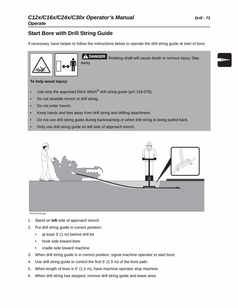
Start Bore with Drill String Guide
If necessary, have helper to follow the instructions below to operate the drill string guide at start of bore.
1. Stand on left side of approach trench.
2. Put drill string guide in correct position:
• at least 3’ (1 m) behind drill bit
• hook side toward bore
• cradle side toward machine
3. When drill string guide is in correct position, signal machine operator to start bore.
4. Use drill string guide to control the first 5’ (1.5 m) of the bore path.
5. When length of bore is 5’ (1.5 m), have machine operator stop machine.
6. When drill string has stopped, remove drill string guide and leave area.
Rotating shaft will cause death or serious injury. Stay away.
To help avoid injury:
• Use only the approved Ditch Witch® drill string guide (p/n 118-079).
• Do not straddle trench or drill string.
• Do not enter trench.
• Keep hands and feet away from drill string and drilling attachment.
• Do not use drill string guide during backreaming or when drill string is being pulled back.
• Only use drill string guide on left side of approach trench.
Drill - 72 C12x/C16x/C24x/C30x Operator’s ManualOperate
Add Rod
If more length is needed, ask a helper to add a rod section.
Disconnect Drill String from Drilling Attachment
1. Stop rotation of drilling attachment.
2. Operate ground drive controls to move machine in reverse 6” (15 cm) to loosen drill string in ground.
3. Shut down engine. See “Shut Down” on page 49.
4. Disconnect drill string from drilling attachment with applicable special tool (p/n 351-272). See “Disassemble Drill String” on page 77.
5. Start engine. See “Start Unit” on page 46.
6. Operate ground drive controls to move unit in reverse 1’ (30 cm), about the length of a rod section.
Add Rod Section
1. Shut down engine.
2. Have helper connect new rod section to drilling attachment.
3. Start engine and set to low throttle.
4. Slowly move machine forward until new rod section and drill string are about 1’ (30 cm) apart.
5. Have helper lightly hold new rod section and drill string so that they are aligned.
6. Rotate drilling attachment to align slip latches of new rod section and drill string.
7. Move unit forward slowly. As soon as new rod section engages drill string, have helper move hands clear.
8. Slightly move forward until slip latch connection is correctly latched.
Rotating shaft will cause death or serious injury. Stay away.
To help avoid injury: Only access drilling attachment with hands when engine is shut down.
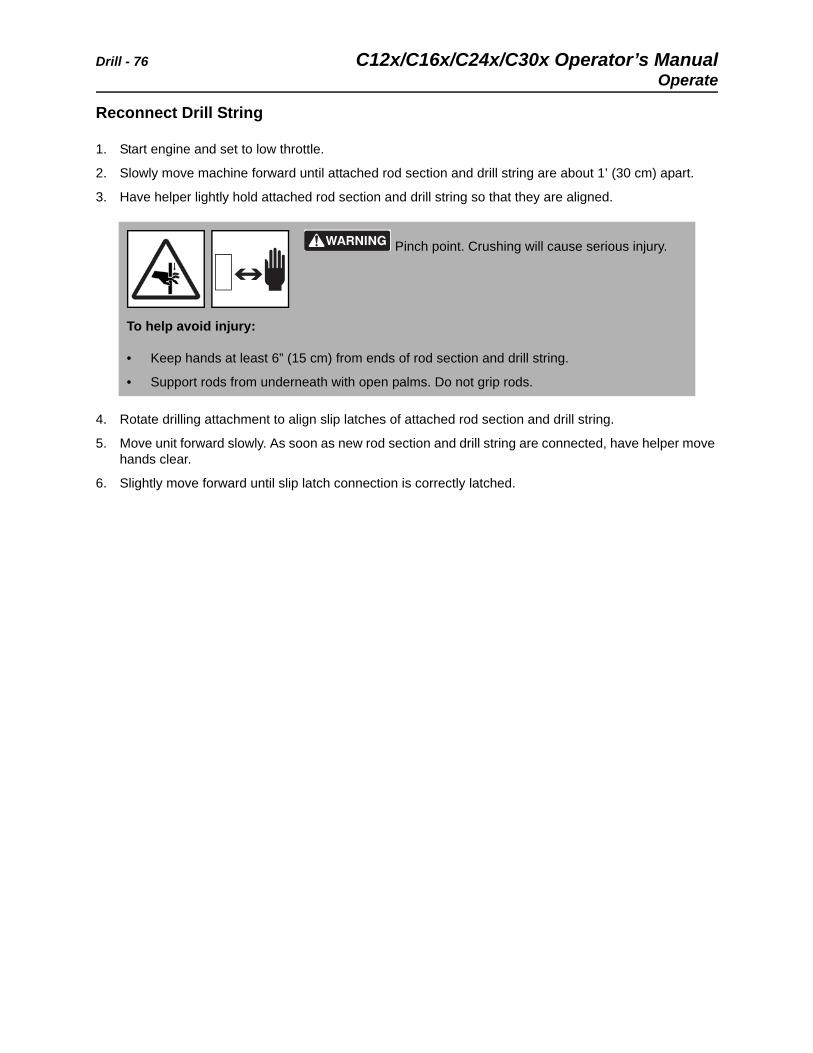
Pinch point. Crushing will cause serious injury.
To help avoid injury:
• Keep hands at least 6” (15 cm) from ends of rod section and drill string.
• Support rods from underneath with open palms. Do not grip rods.
C12x/C16x/C24x/C30x Operator’s Manual Drill - 73
Operate
Backream
After drill bit enters target trench, the bore hole may be enlarged by changing the drill bit to a reamer and pulling it back through the initial bore.
Single pass
1. Shut down engine. See “Shut Down” on page 49.
2. Remove drill bit and install appropriate reamer.
3. Start engine and begin clockwise rotation. See “Start Unit” on page 46.
4. Slowly drive in reverse while maintaining rotation. See “Drive” on page 47. When reamer exits the approach trench, stop rotation immediately.
Multiple passes
1. Repeat steps 1-5.
2. Install drill bit.
3. Push drill string through bore. Do not rotate.
4. At final pass, install product. See “Install Product” on page 74.
NOTICE: Incorrect use may damage components and increase wear.
• Do not try to increase hole size too much in one pass. Make several passes using successively larger reamers.
• Keep drill string straight and aligned with drilling attachment. Sharp bends can cause rod failure.
• Never have more than 30’ (9 m) of exposed rod outside the bore. Remove rods as necessary. See “Remove Rod” on page 75.
IMPORTANT: Always rotate clockwise during backreaming. Rotate counterclockwise only if drill bit or reamer is blocked in bore.
Drill - 74 C12x/C16x/C24x/C30x Operator’s ManualOperate
Install Product
To install product, pull it through the bore after drilling or at final pass of backreaming.
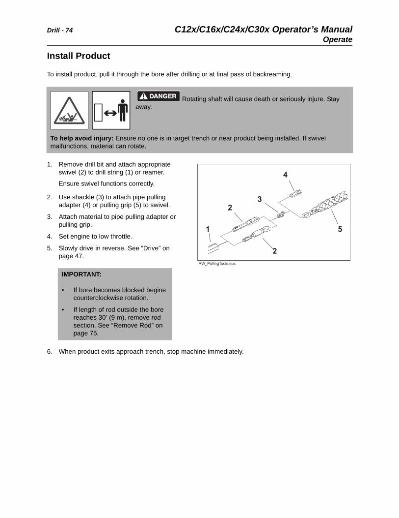
1. Remove drill bit and attach appropriate swivel (2) to drill string (1) or reamer.
Ensure swivel functions correctly.
2. Use shackle (3) to attach pipe pulling adapter (4) or pulling grip (5) to swivel.
3. Attach material to pipe pulling adapter or pulling grip.
4. Set engine to low throttle.
5. Slowly drive in reverse. See “Drive” on page 47.
6. When product exits approach trench, stop machine immediately.
Rotating shaft will cause death or seriously injure. Stay away.
To help avoid injury: Ensure no one is in target trench or near product being installed. If swivel malfunctions, material can rotate.
IMPORTANT:
• If bore becomes blocked begine counterclockwise rotation.
• If length of rod outside the bore reaches 30’ (9 m), remove rod section. See “Remove Rod” on page 75.
C12x/C16x/C24x/C30x Operator’s Manual Drill - 75
Operate
Remove Rod
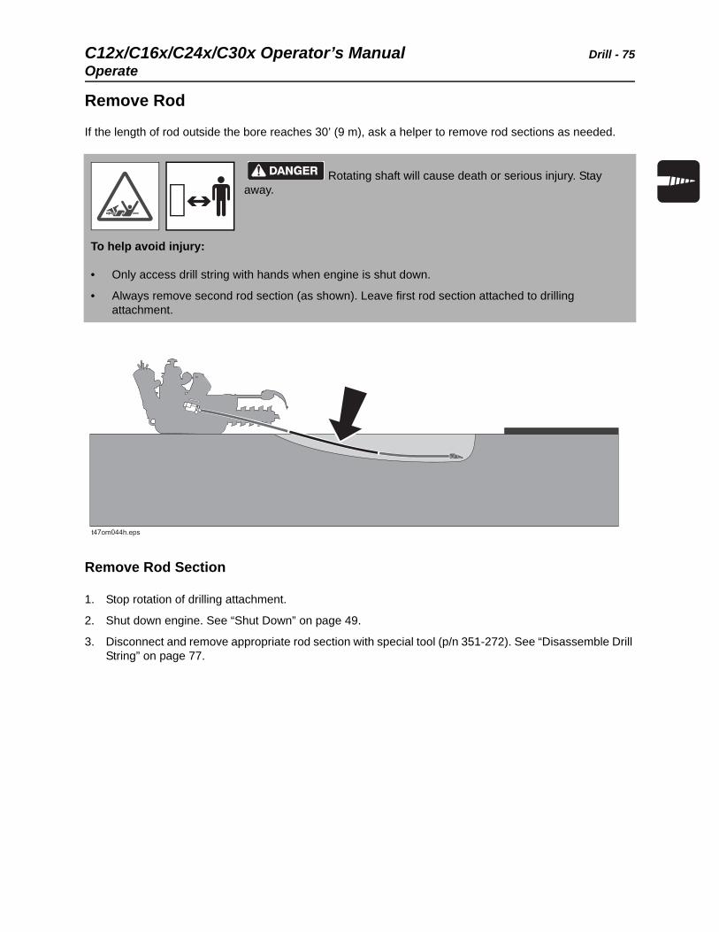
If the length of rod outside the bore reaches 30’ (9 m), ask a helper to remove rod sections as needed.
Remove Rod Section
1. Stop rotation of drilling attachment.
2. Shut down engine. See “Shut Down” on page 49.
3. Disconnect and remove appropriate rod section with special tool (p/n 351-272). See “Disassemble Drill String” on page 77.
Rotating shaft will cause death or serious injury. Stay away.
To help avoid injury:
• Only access drill string with hands when engine is shut down.
• Always remove second rod section (as shown). Leave first rod section attached to drilling attachment.
Drill - 76 C12x/C16x/C24x/C30x Operator’s ManualOperate
Reconnect Drill String
1. Start engine and set to low throttle.
2. Slowly move machine forward until attached rod section and drill string are about 1’ (30 cm) apart.
3. Have helper lightly hold attached rod section and drill string so that they are aligned.
4. Rotate drilling attachment to align slip latches of attached rod section and drill string.
5. Move unit forward slowly. As soon as new rod section and drill string are connected, have helper move hands clear.
6. Slightly move forward until slip latch connection is correctly latched.
Pinch point. Crushing will cause serious injury.
To help avoid injury:
• Keep hands at least 6” (15 cm) from ends of rod section and drill string.
• Support rods from underneath with open palms. Do not grip rods.
C12x/C16x/C24x/C30x Operator’s Manual Drill - 77
Finish Job
Finish Job
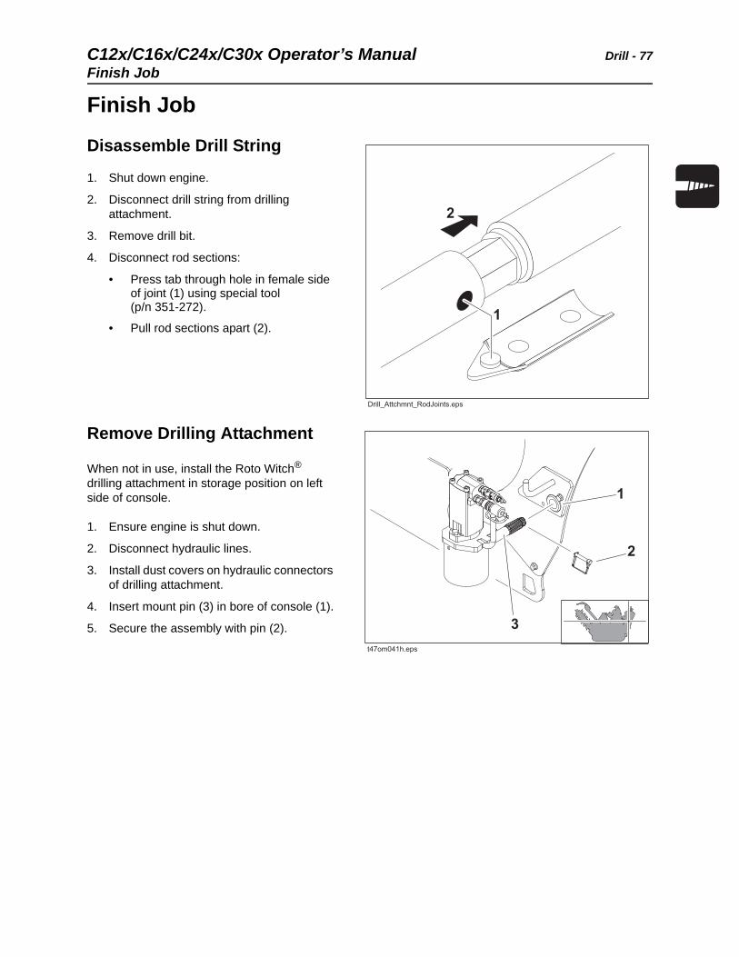
Disassemble Drill String
1. Shut down engine.
2. Disconnect drill string from drilling attachment.
3. Remove drill bit.
4. Disconnect rod sections:
• Press tab through hole in female side of joint (1) using special tool (p/n 351-272).
• Pull rod sections apart (2).
Remove Drilling Attachment
When not in use, install the Roto Witch® drilling attachment in storage position on left side of console.
1. Ensure engine is shut down.
2. Disconnect hydraulic lines.
3. Install dust covers on hydraulic connectors of drilling attachment.
4. Insert mount pin (3) in bore of console (1).
5. Secure the assembly with pin (2).

Drill - 78 C12x/C16x/C24x/C30x Operator’s ManualFinish Job
C12x/C16x/C24x/C30x Operator’s Manual Systems and Equipment - 79
Systems and Equipment
Chapter Contents
Chain, Teeth, and Sprockets . . . . . . . . . . . . . . . . . 80
• Chain and Tooth Maintenance . . . . . . . . . . . . . . . . . . . . . . . . . . . . . . . .80
• Chain Types . . . . . . . . . . . . . . . . . . . . . . . . . . . . . . . . . . . . . . . . . . . . . .80
• Chain Selection . . . . . . . . . . . . . . . . . . . . . . . . . . . . . . . . . . . . . . . . . . . .81
Optional Equipment . . . . . . . . . . . . . . . . . . . . . . . . 82
• Backfill blade. . . . . . . . . . . . . . . . . . . . . . . . . . . . . . . . . . . . . . . . . . . . . .83
• Drilling Attachment . . . . . . . . . . . . . . . . . . . . . . . . . . . . . . . . . . . . . . . . .83
Counterweighting . . . . . . . . . . . . . . . . . . . . . . . . . . 84
Systems and Equipment - 80 C12x/C16x/C24x/C30x Operator’s ManualChain, Teeth, and Sprockets
Chain, Teeth, and Sprockets
Chain and Tooth Maintenance
• Always replace sprockets at the same time you replace the digging chain. Sprockets and chain are designed to work together. Replacing one without the other will cause premature wear of the new part.
• Keep digging teeth sharp. Using dull, worn teeth will decrease production and increase shock load to other trencher components. It can also cause chain stretch, which leads to premature chain wear and failure.
• Maintain the proper amount of tension on the digging chain. Overtightening will cause chain stretch and loss of machine performance.
• Use the tooth pattern most appropriate for your digging conditions. If you move to a different soil type,
contact your Ditch Witch® dealer for information about the most effective chain type and tooth pattern.
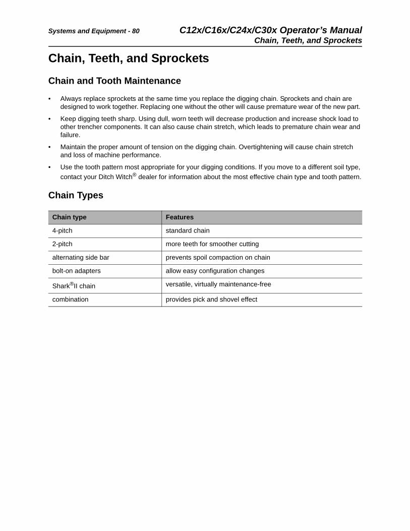
Chain Types
Chain type Features
4-pitch standard chain
2-pitch more teeth for smoother cutting
alternating side bar prevents spoil compaction on chain
bolt-on adapters allow easy configuration changes
Shark®II chain versatile, virtually maintenance-free
combination provides pick and shovel effect
C12x/C16x/C24x/C30x Operator’s Manual Systems and Equipment - 81
Chain, Teeth, and Sprockets
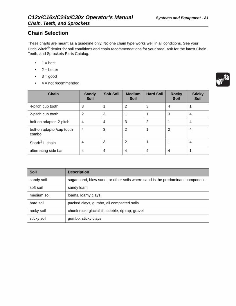
Chain Selection
These charts are meant as a guideline only. No one chain type works well in all conditions. See your
Ditch Witch® dealer for soil conditions and chain recommendations for your area. Ask for the latest Chain, Teeth, and Sprockets Parts Catalog.
• 1 = best
• 2 = better
• 3 = good
• 4 = not recommended
Chain Sandy Soil
Soft Soil Medium Soil
Hard Soil Rocky Soil
Sticky Soil
4-pitch cup tooth 3 1 2 3 4 1
2-pitch cup tooth 2 3 1 1 3 4
bolt-on adaptor, 2-pitch 4 4 3 2 1 4
bolt-on adaptor/cup tooth combo
4 3 2 1 2 4
Shark® II chain 4 3 2 1 1 4
alternating side bar 4 4 4 4 4 1
Soil Description
sandy soil sugar sand, blow sand, or other soils where sand is the predominant component
soft soil sandy loam
medium soil loams, loamy clays
hard soil packed clays, gumbo, all compacted soils
rocky soil chunk rock, glacial till, cobble, rip rap, gravel
sticky soil gumbo, sticky clays
Systems and Equipment - 82 C12x/C16x/C24x/C30x Operator’s ManualOptional Equipment
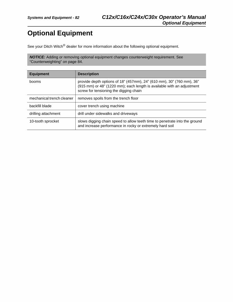
Optional Equipment
See your Ditch Witch® dealer for more information about the following optional equipment.
NOTICE: Adding or removing optional equipment changes counterweight requirement. See “Counterweighting” on page 84.
Equipment Description
booms provide depth options of 18” (457mm), 24” (610 mm), 30” (760 mm), 36” (915 mm) or 48” (1220 mm); each length is available with an adjustment screw for tensioning the digging chain
mechanical trench cleaner removes spoils from the trench floor
backfill blade cover trench using machine
drilling attachment drill under sidewalks and driveways
10-tooth sprocket slows digging chain speed to allow teeth time to penetrate into the ground and increase performance in rocky or extremely hard soil
C12x/C16x/C24x/C30x Operator’s Manual Systems and Equipment - 83
Optional Equipment
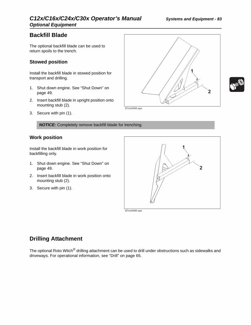
Backfill Blade
The optional backfill blade can be used to return spoils to the trench.
Stowed position
Install the backfill blade in stowed position for transport and drilling.
1. Shut down engine. See “Shut Down” on page 49.
2. Insert backfill blade in upright position onto mounting stub (2).
3. Secure with pin (1).
Work position
Install the backfill blade in work position for backfilling only.
1. Shut down engine. See “Shut Down” on page 49.
2. Insert backfill blade in work position onto mounting stub (2).
3. Secure with pin (1).
Drilling Attachment
The optional Roto Witch® drilling attachment can be used to drill under obstructions such as sidewalks and driveways. For operational information, see “Drill” on page 65.
NOTICE: Completely remove backfill blade for trenching.
Systems and Equipment - 84 C12x/C16x/C24x/C30x Operator’s ManualCounterweighting
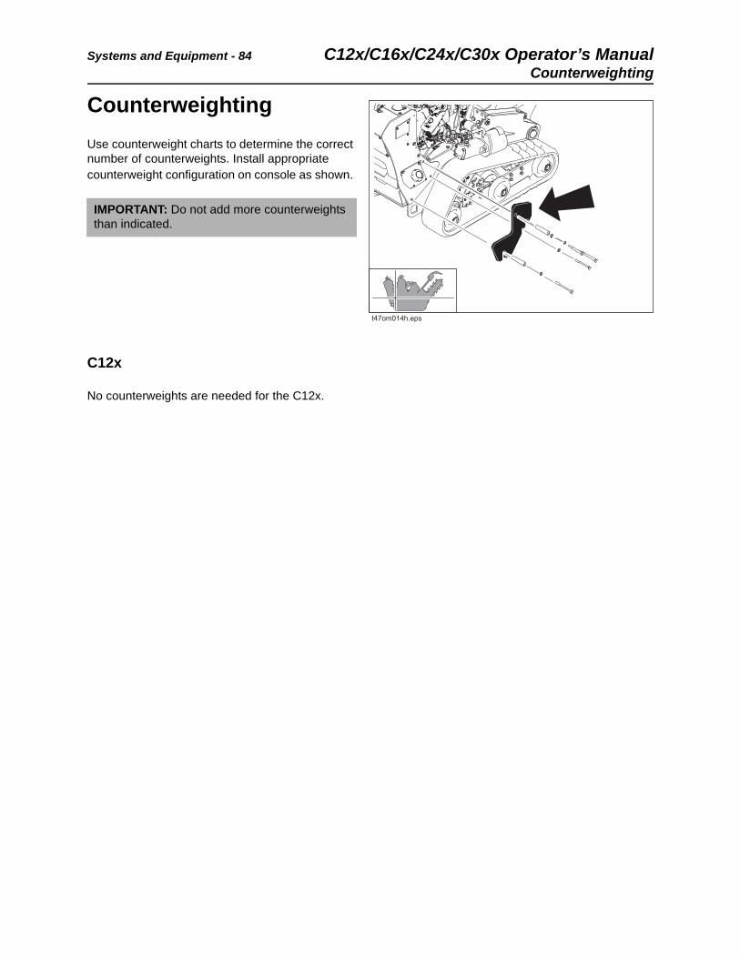
Counterweighting
Use counterweight charts to determine the correct number of counterweights. Install appropriate counterweight configuration on console as shown.
C12x
No counterweights are needed for the C12x.
IMPORTANT: Do not add more counterweights than indicated.
C12x/C16x/C24x/C30x Operator’s Manual Systems and Equipment - 85
Counterweighting
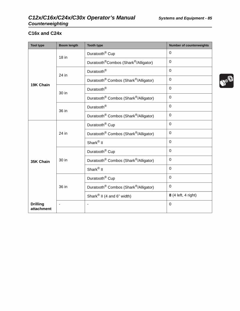
C16x and C24x
Tool type Boom length Tooth type Number of counterweights
19K Chain
18 inDuratooth® Cup 0
Duratooth®Combos (Shark®/Alligator) 0
24 inDuratooth® 0
Duratooth® Combos (Shark®/Alligator) 0
30 inDuratooth® 0
Duratooth® Combos (Shark®/Alligator) 0
36 inDuratooth® 0
Duratooth® Combos (Shark®/Alligator) 0
35K Chain
24 in
Duratooth® Cup 0
Duratooth® Combos (Shark®/Alligator) 0
Shark® II 0
30 in
Duratooth® Cup 0
Duratooth® Combos (Shark®/Alligator) 0
Shark® II 0
36 in
Duratooth® Cup 0
Duratooth® Combos (Shark®/Alligator) 0
Shark® II (4 and 6” width) 8 (4 left, 4 right)
Drilling attachment
- - 0
Systems and Equipment - 86 C12x/C16x/C24x/C30x Operator’s ManualCounterweighting
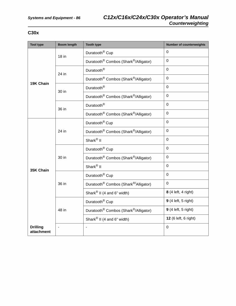
C30x
Tool type Boom length Tooth type Number of counterweights
19K Chain
18 inDuratooth® Cup 0
Duratooth® Combos (Shark®/Alligator) 0
24 inDuratooth® 0
Duratooth® Combos (Shark®/Alligator) 0
30 inDuratooth® 0
Duratooth® Combos (Shark®/Alligator) 0
36 inDuratooth® 0
Duratooth® Combos (Shark®/Alligator) 0
35K Chain
24 in
Duratooth® Cup 0
Duratooth® Combos (Shark®/Alligator) 0
Shark® II 0
30 in
Duratooth® Cup 0
Duratooth® Combos (Shark®/Alligator) 0
Shark® II 0
36 in
Duratooth® Cup 0
Duratooth® Combos (Shark®/Alligator) 0
Shark® II (4 and 6” width) 8 (4 left, 4 right)
48 in
Duratooth® Cup 9 (4 left, 5 right)
Duratooth® Combos (Shark®/Alligator) 9 (4 left, 5 right)
Shark® II (4 and 6” width) 12 (6 left, 6 right)
Drilling attachment
- - 0
C12x/C16x/C24x/C30x Operator’s Manual Complete the Job - 87
Complete the Job
Chapter Contents
Restore Jobsite . . . . . . . . . . . . . . . . . . . . . . . . . . . . 88
Rinse Equipment . . . . . . . . . . . . . . . . . . . . . . . . . . 88
Stow Tools . . . . . . . . . . . . . . . . . . . . . . . . . . . . . . . 88
Complete the Job - 88 C12x/C16x/C24x/C30x Operator’s ManualRestore Jobsite
Restore Jobsite
After product is installed, return spoils to the trench with optional backfill blade, shovels, or small earth-moving equipment. See “Backfill Blade” on page 83.
Rinse Equipment
Spray water onto equipment to remove dirt and mud.
Stow Tools
Ensure all bits, pullback devices, and other tools are loaded and properly secured on trailer.
NOTICE:
• Do not spray water onto operator’s console. Electrical components could be damaged. Wipe down instead.
• Ensure all mud and debris are rinsed from tracks before parking overnight.

C12x/C16x/C24x/C30x Operator’s Manual Service - 89
Service
Chapter Contents
Precautions . . . . . . . . . . . . . . . . . . . . . . . . . . . . . . . 90
Recommended Lubricants/Service Key . . . . . . . . 91
• Approved Fuel. . . . . . . . . . . . . . . . . . . . . . . . . . . . . . . . . . . . . . . . . . . . .91
Engine Oil Temperature Chart . . . . . . . . . . . . . . . . 92
• C12x Honda GX390® . . . . . . . . . . . . . . . . . . . . . . . . . . . . . . . . . . . . . . .92
• C16x and C30x Briggs and Stratton® . . . . . . . . . . . . . . . . . . . . . . . . . . .92
• C24x Honda GX690® . . . . . . . . . . . . . . . . . . . . . . . . . . . . . . . . . . . . . . .93
Each Use . . . . . . . . . . . . . . . . . . . . . . . . . . . . . . . . . 94
10 Hour . . . . . . . . . . . . . . . . . . . . . . . . . . . . . . . . . 101
20 Hour. . . . . . . . . . . . . . . . . . . . . . . . . . . . . . . . . . 105
50 Hour . . . . . . . . . . . . . . . . . . . . . . . . . . . . . . . . . 106
100 Hour . . . . . . . . . . . . . . . . . . . . . . . . . . . . . . . . 108
500 Hour . . . . . . . . . . . . . . . . . . . . . . . . . . . . . . . . 111
As Needed . . . . . . . . . . . . . . . . . . . . . . . . . . . . . . 112
Service - 90 C12x/C16x/C24x/C30x Operator’s ManualPrecautions
Precautions
Welding Precaution
Washing Precaution
Misuse of machine can cause death or serious injury. Read and understand operator’s manual and all other safety instructions before use.
To help avoid injury:
• Unless otherwise instructed, all service should be performed with engine off and engine cool.
• Refer to engine manufacturer’s manual for engine maintenance instructions.
• Lower unstowed attachments to ground before servicing equipment.
• Wear personal protective equipment.
NOTICE: Welding can damage electronics.
• Disconnect battery before welding to prevent damage to battery.
• Connect welder ground clamp close to welding point and ensure no electronic components are in the ground path.
NOTICE: Water can damage electrical components. When cleaning equipment, do not spray electrical components with water.
C12x/C16x/C24x/C30x Operator’s Manual Service - 91
Recommended Lubricants/Service Key
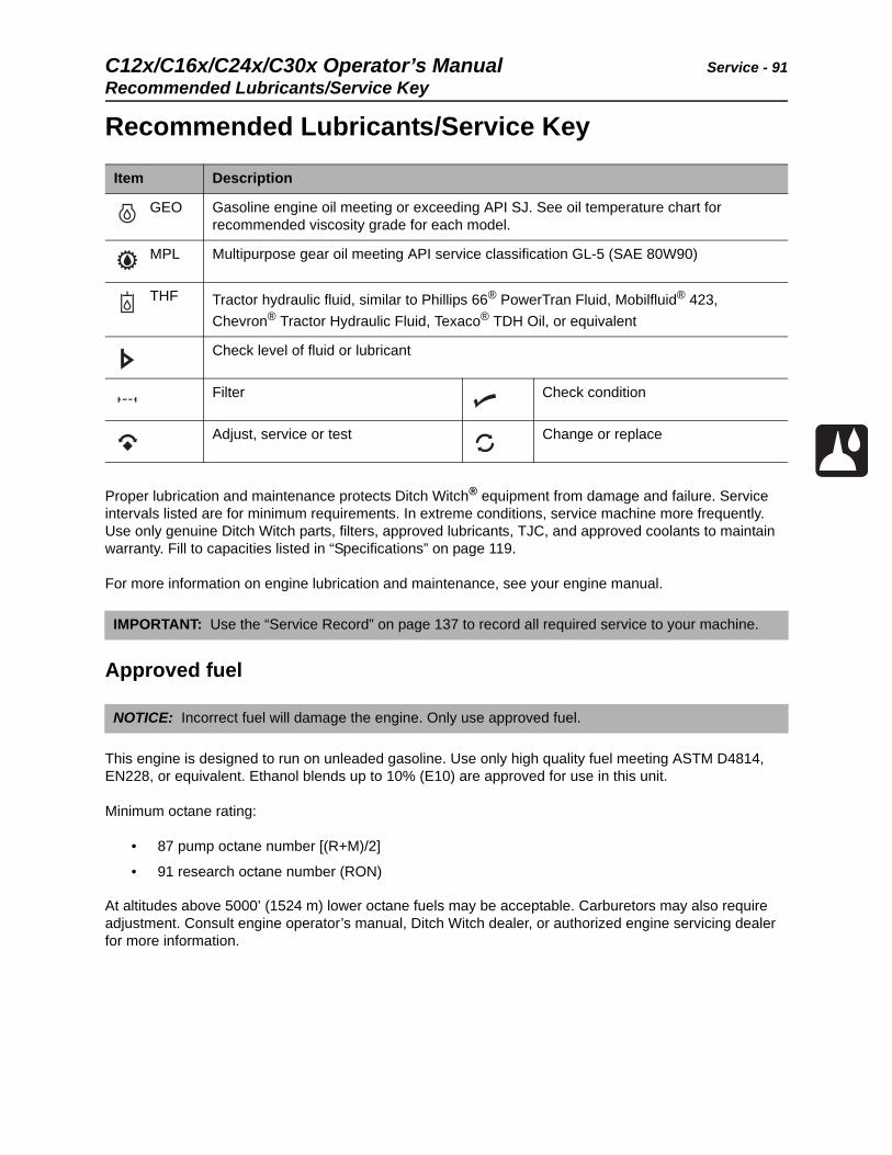
Recommended Lubricants/Service Key
Proper lubrication and maintenance protects Ditch Witch® equipment from damage and failure. Service intervals listed are for minimum requirements. In extreme conditions, service machine more frequently. Use only genuine Ditch Witch parts, filters, approved lubricants, TJC, and approved coolants to maintain warranty. Fill to capacities listed in “Specifications” on page 119.
For more information on engine lubrication and maintenance, see your engine manual.
Approved fuel
This engine is designed to run on unleaded gasoline. Use only high quality fuel meeting ASTM D4814, EN228, or equivalent. Ethanol blends up to 10% (E10) are approved for use in this unit.
Minimum octane rating:
• 87 pump octane number [(R+M)/2]
• 91 research octane number (RON)
At altitudes above 5000’ (1524 m) lower octane fuels may be acceptable. Carburetors may also require adjustment. Consult engine operator’s manual, Ditch Witch dealer, or authorized engine servicing dealer for more information.
Item Description
GEO Gasoline engine oil meeting or exceeding API SJ. See oil temperature chart for recommended viscosity grade for each model.
MPL Multipurpose gear oil meeting API service classification GL-5 (SAE 80W90)
THF Tractor hydraulic fluid, similar to Phillips 66® PowerTran Fluid, Mobilfluid® 423,
Chevron® Tractor Hydraulic Fluid, Texaco® TDH Oil, or equivalent
Check level of fluid or lubricant
Filter Check condition
Adjust, service or test Change or replace
IMPORTANT: Use the “Service Record” on page 137 to record all required service to your machine.
NOTICE: Incorrect fuel will damage the engine. Only use approved fuel.
Service - 92 C12x/C16x/C24x/C30x Operator’s ManualEngine Oil Temperature Chart
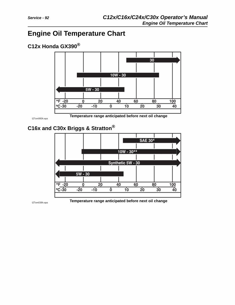
Engine Oil Temperature Chart
C12x Honda GX390®
C16x and C30x Briggs & Stratton®
Temperature range anticipated before next oil change
Temperature range anticipated before next oil change
C12x/C16x/C24x/C30x Operator’s Manual Service - 93
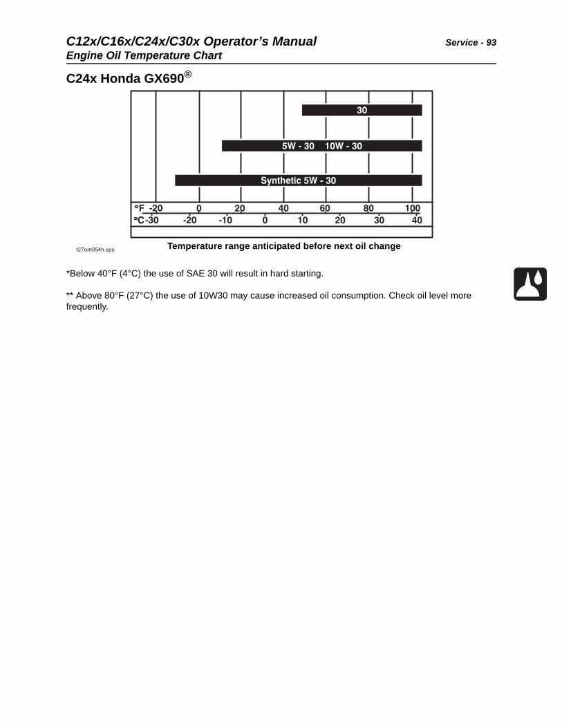
Engine Oil Temperature Chart
C24x Honda GX690®
*Below 40°F (4°C) the use of SAE 30 will result in hard starting.
** Above 80°F (27°C) the use of 10W30 may cause increased oil consumption. Check oil level more frequently.
Temperature range anticipated before next oil change
Service - 94 C12x/C16x/C24x/C30x Operator’s ManualEach Use
Each Use
Engine
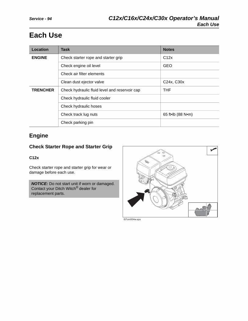
Check Starter Rope and Starter Grip
C12x
Check starter rope and starter grip for wear or damage before each use.
Location Task Notes
ENGINE Check starter rope and starter grip C12x
Check engine oil level GEO
Check air filter elements
Clean dust ejector valve C24x, C30x
TRENCHER Check hydraulic fluid level and reservoir cap THF
Check hydraulic fluid cooler
Check hydraulic hoses
Check track lug nuts 65 ft•lb (88 N•m)
Check parking pin
NOTICE: Do not start unit if worn or damaged. Contact your Ditch Witch® dealer for replacement parts.
t57om004w.eps
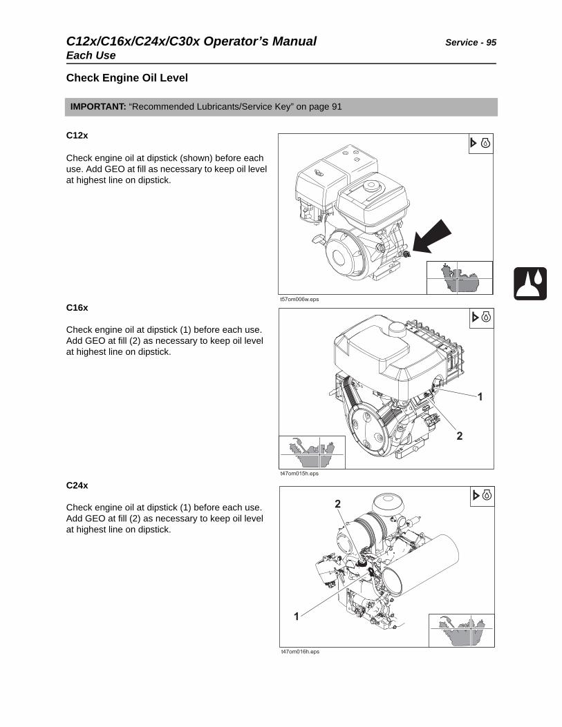
C12x/C16x/C24x/C30x Operator’s Manual Service - 95
Each Use
Check Engine Oil Level
C12x
Check engine oil at dipstick (shown) before each use. Add GEO at fill as necessary to keep oil level at highest line on dipstick.
C16x
Check engine oil at dipstick (1) before each use. Add GEO at fill (2) as necessary to keep oil level at highest line on dipstick.
C24x
Check engine oil at dipstick (1) before each use. Add GEO at fill (2) as necessary to keep oil level at highest line on dipstick.
IMPORTANT: “Recommended Lubricants/Service Key” on page 91
t57om006w.eps
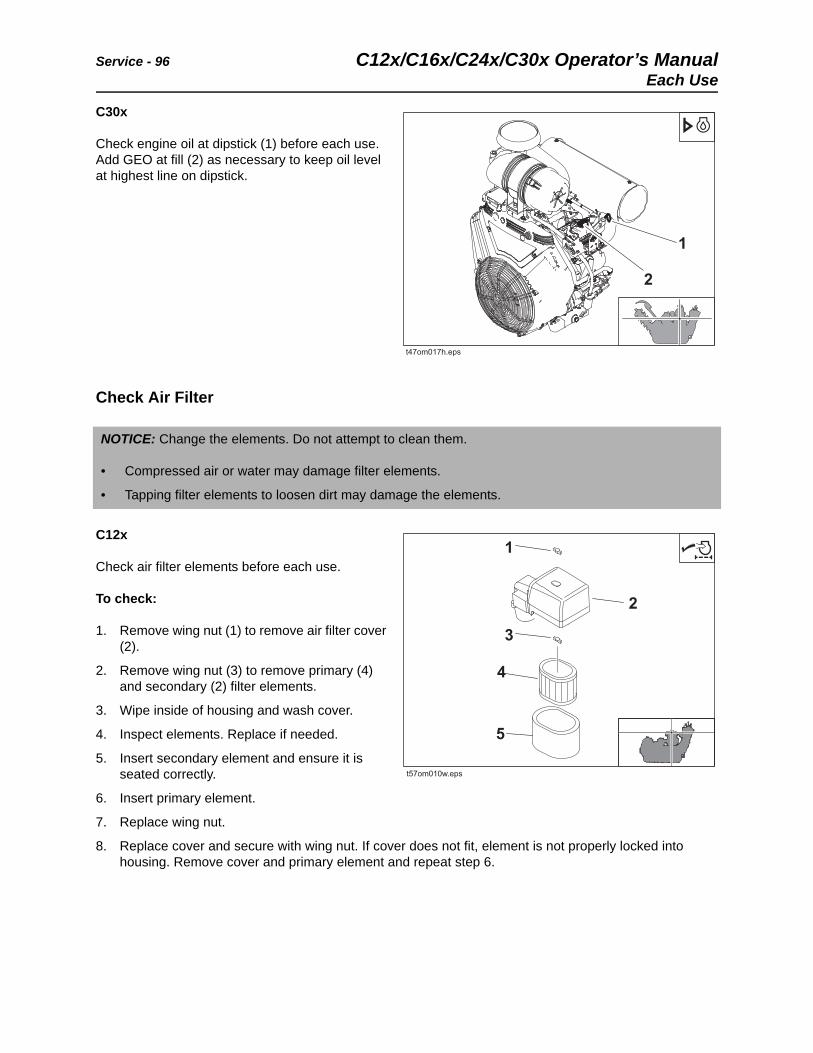
Service - 96 C12x/C16x/C24x/C30x Operator’s ManualEach Use
C30x
Check engine oil at dipstick (1) before each use. Add GEO at fill (2) as necessary to keep oil level at highest line on dipstick.
Check Air Filter
C12x
Check air filter elements before each use.
To check:
1. Remove wing nut (1) to remove air filter cover (2).
2. Remove wing nut (3) to remove primary (4) and secondary (2) filter elements.
3. Wipe inside of housing and wash cover.
4. Inspect elements. Replace if needed.
5. Insert secondary element and ensure it is seated correctly.
6. Insert primary element.
7. Replace wing nut.
8. Replace cover and secure with wing nut. If cover does not fit, element is not properly locked into housing. Remove cover and primary element and repeat step 6.
NOTICE: Change the elements. Do not attempt to clean them.
• Compressed air or water may damage filter elements.
• Tapping filter elements to loosen dirt may damage the elements.
t57om010w.eps
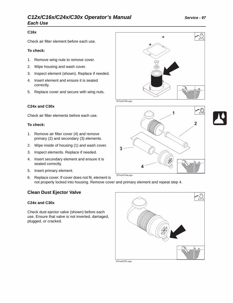
C12x/C16x/C24x/C30x Operator’s Manual Service - 97
Each Use
C16x
Check air filter element before each use.
To check:
1. Remove wing nuts to remove cover.
2. Wipe housing and wash cover.
3. Inspect element (shown). Replace if needed.
4. Insert element and ensure it is seated correctly.
5. Replace cover and secure with wing nuts.
C24x and C30x
Check air filter elements before each use.
To check:
1. Remove air filter cover (4) and remove primary (2) and secondary (3) elements.
2. Wipe inside of housing (1) and wash cover.
3. Inspect elements. Replace if needed.
4. Insert secondary element and ensure it is seated correctly.
5. Insert primary element.
6. Replace cover. If cover does not fit, element is not properly locked into housing. Remove cover and primary element and repeat step 4.
Clean Dust Ejector Valve
C24x and C30x
Check dust ejector valve (shown) before each use. Ensure that valve is not inverted, damaged, plugged, or cracked.
t57om014w.eps
1
2
3
4
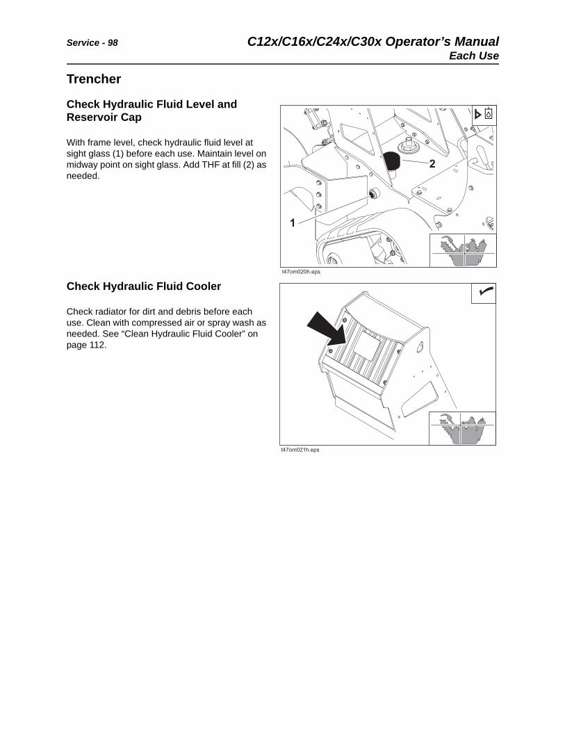
Service - 98 C12x/C16x/C24x/C30x Operator’s ManualEach Use
Trencher
Check Hydraulic Fluid Level and Reservoir Cap
With frame level, check hydraulic fluid level at sight glass (1) before each use. Maintain level on midway point on sight glass. Add THF at fill (2) as needed.
Check Hydraulic Fluid Cooler
Check radiator for dirt and debris before each use. Clean with compressed air or spray wash as needed. See “Clean Hydraulic Fluid Cooler” on page 112.
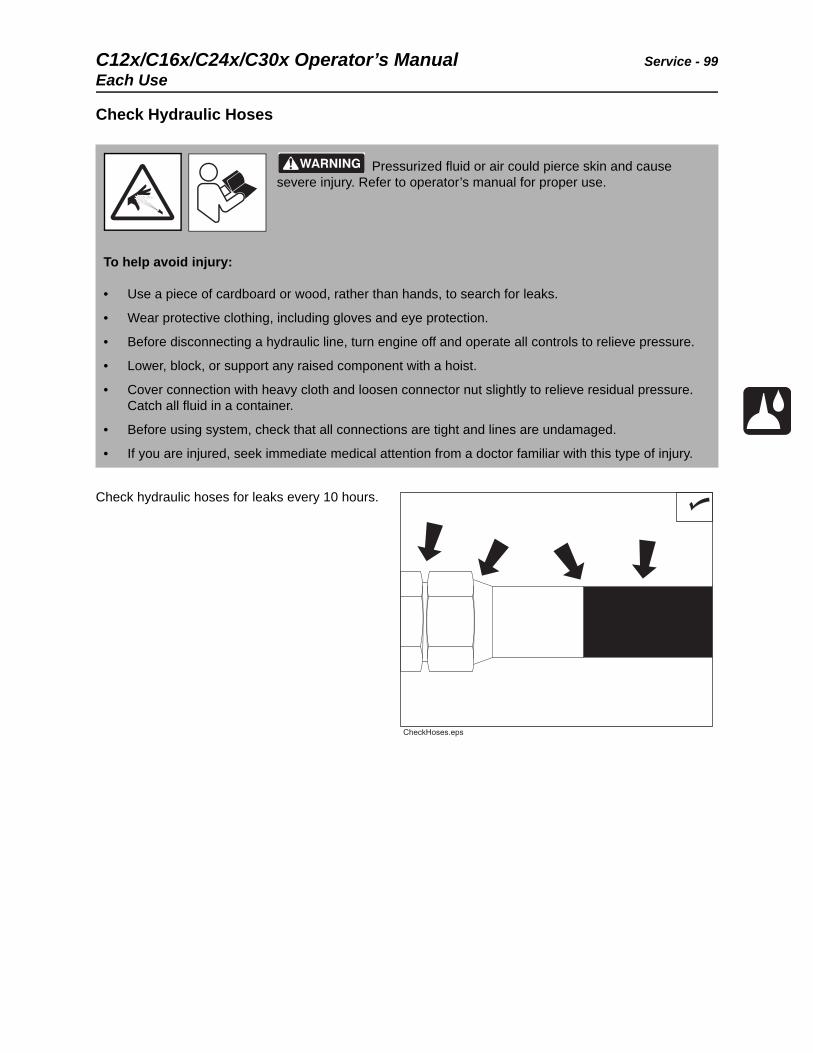
C12x/C16x/C24x/C30x Operator’s Manual Service - 99
Each Use
Check Hydraulic Hoses
Check hydraulic hoses for leaks every 10 hours.
Pressurized fluid or air could pierce skin and cause severe injury. Refer to operator’s manual for proper use.
To help avoid injury:
• Use a piece of cardboard or wood, rather than hands, to search for leaks.
• Wear protective clothing, including gloves and eye protection.
• Before disconnecting a hydraulic line, turn engine off and operate all controls to relieve pressure.
• Lower, block, or support any raised component with a hoist.
• Cover connection with heavy cloth and loosen connector nut slightly to relieve residual pressure. Catch all fluid in a container.
• Before using system, check that all connections are tight and lines are undamaged.
• If you are injured, seek immediate medical attention from a doctor familiar with this type of injury.
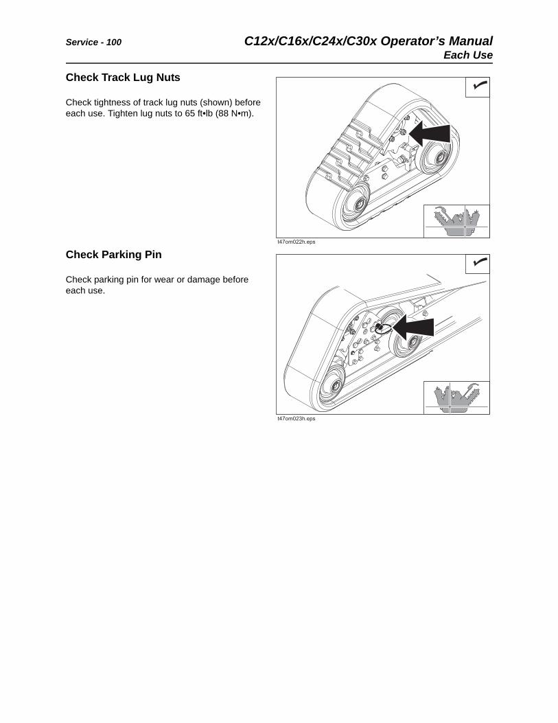
Service - 100 C12x/C16x/C24x/C30x Operator’s ManualEach Use
Check Track Lug Nuts
Check tightness of track lug nuts (shown) before each use. Tighten lug nuts to 65 ft•lb (88 N•m).
Check Parking Pin
Check parking pin for wear or damage before each use.
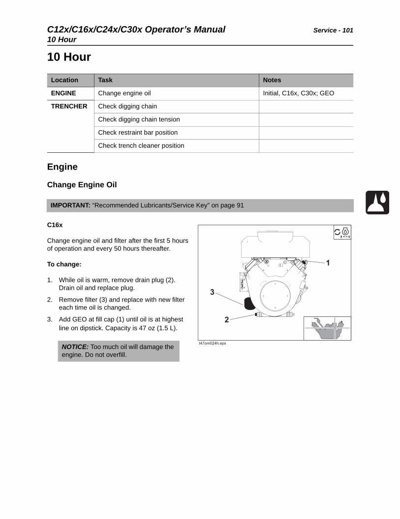
C12x/C16x/C24x/C30x Operator’s Manual Service - 101
10 Hour
10 Hour
Engine
Change Engine Oil
C16x
Change engine oil and filter after the first 5 hours of operation and every 50 hours thereafter.
To change:
1. While oil is warm, remove drain plug (2). Drain oil and replace plug.
2. Remove filter (3) and replace with new filter each time oil is changed.
3. Add GEO at fill cap (1) until oil is at highest line on dipstick. Capacity is 47 oz (1.5 L).
Location Task Notes
ENGINE Change engine oil Initial, C16x, C30x; GEO
TRENCHER Check digging chain
Check digging chain tension
Check restraint bar position
Check trench cleaner position
IMPORTANT: “Recommended Lubricants/Service Key” on page 91
NOTICE: Too much oil will damage the engine. Do not overfill.
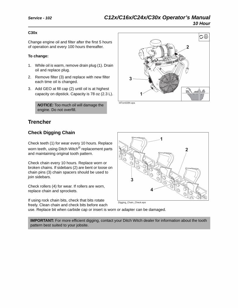
Service - 102 C12x/C16x/C24x/C30x Operator’s Manual10 Hour
C30x
Change engine oil and filter after the first 5 hours of operation and every 100 hours thereafter.
To change:
1. While oil is warm, remove drain plug (1). Drain oil and replace plug.
2. Remove filter (3) and replace with new filter each time oil is changed.
3. Add GEO at fill cap (2) until oil is at highest capacity on dipstick. Capacity is 78 oz (2.3 L).
Trencher
Check Digging Chain
Check teeth (1) for wear every 10 hours. Replace
worn teeth, using Ditch Witch® replacement parts and maintaining original tooth pattern.
Check chain every 10 hours. Replace worn or broken chains. If sidebars (2) are bent or loose on chain pins (3) chain spacers should be used to join sidebars.
Check rollers (4) for wear. If rollers are worn, replace chain and sprockets.
If using rock chain bits, check that bits rotate freely. Clean chain and check bits before each use. Replace bit when carbide cap or insert is worn or adapter can be damaged.
NOTICE: Too much oil will damage the engine. Do not overfill.
IMPORTANT: For more efficient digging, contact your Ditch Witch dealer for information about the tooth pattern best suited to your jobsite.
3
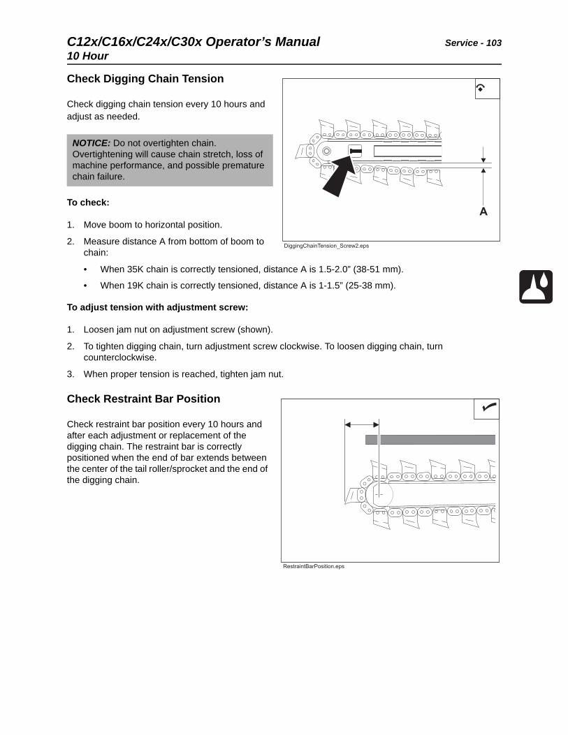
C12x/C16x/C24x/C30x Operator’s Manual Service - 103
10 Hour
Check Digging Chain Tension
Check digging chain tension every 10 hours and adjust as needed.
To check:
1. Move boom to horizontal position.
2. Measure distance A from bottom of boom to chain:
• When 35K chain is correctly tensioned, distance A is 1.5-2.0” (38-51 mm).
• When 19K chain is correctly tensioned, distance A is 1-1.5” (25-38 mm).
To adjust tension with adjustment screw:
1. Loosen jam nut on adjustment screw (shown).
2. To tighten digging chain, turn adjustment screw clockwise. To loosen digging chain, turn counterclockwise.
3. When proper tension is reached, tighten jam nut.
Check Restraint Bar Position
Check restraint bar position every 10 hours and after each adjustment or replacement of the digging chain. The restraint bar is correctly positioned when the end of bar extends between the center of the tail roller/sprocket and the end of the digging chain.
NOTICE: Do not overtighten chain. Overtightening will cause chain stretch, loss of machine performance, and possible premature chain failure.
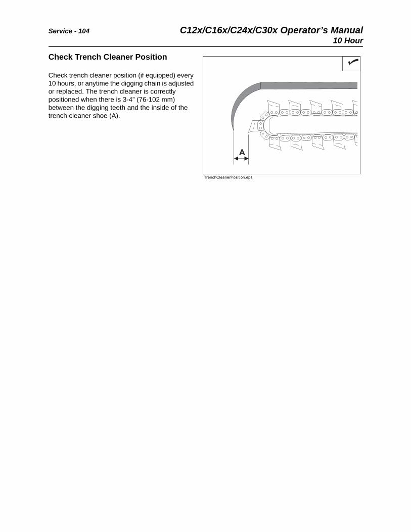
Service - 104 C12x/C16x/C24x/C30x Operator’s Manual10 Hour
Check Trench Cleaner Position
Check trench cleaner position (if equipped) every 10 hours, or anytime the digging chain is adjusted or replaced. The trench cleaner is correctly positioned when there is 3-4” (76-102 mm) between the digging teeth and the inside of the trench cleaner shoe (A).
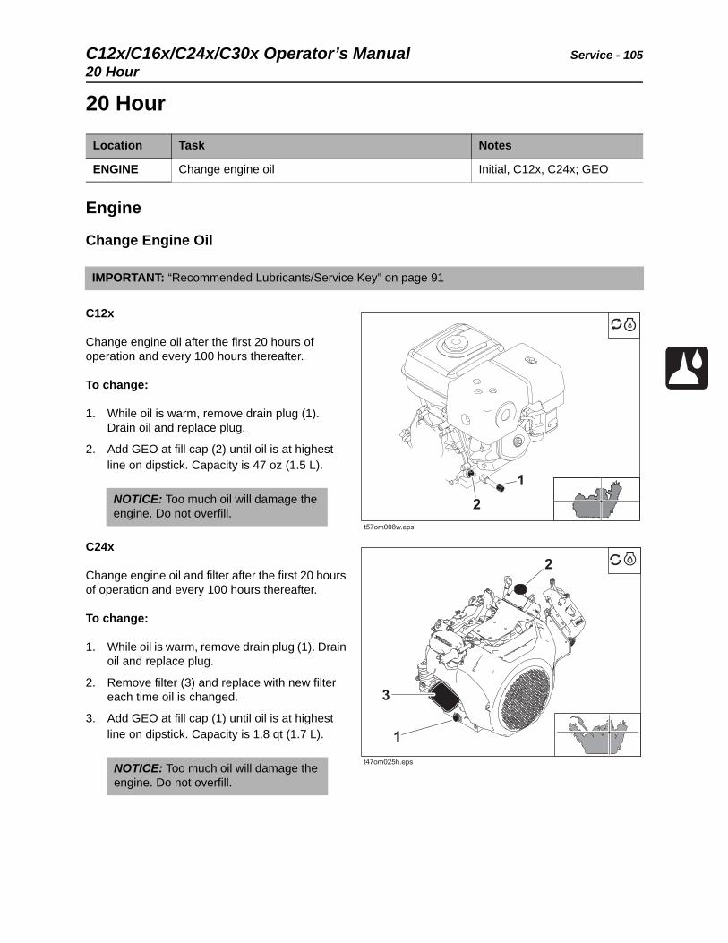
C12x/C16x/C24x/C30x Operator’s Manual Service - 105
20 Hour
20 Hour
Engine
Change Engine Oil
C12x
Change engine oil after the first 20 hours of operation and every 100 hours thereafter.
To change:
1. While oil is warm, remove drain plug (1). Drain oil and replace plug.
2. Add GEO at fill cap (2) until oil is at highest line on dipstick. Capacity is 47 oz (1.5 L).
C24x
Change engine oil and filter after the first 20 hours of operation and every 100 hours thereafter.
To change:
1. While oil is warm, remove drain plug (1). Drain oil and replace plug.
2. Remove filter (3) and replace with new filter each time oil is changed.
3. Add GEO at fill cap (1) until oil is at highest line on dipstick. Capacity is 1.8 qt (1.7 L).
Location Task Notes
ENGINE Change engine oil Initial, C12x, C24x; GEO
IMPORTANT: “Recommended Lubricants/Service Key” on page 91
NOTICE: Too much oil will damage the engine. Do not overfill.
NOTICE: Too much oil will damage the engine. Do not overfill.
t57om008w.eps
3
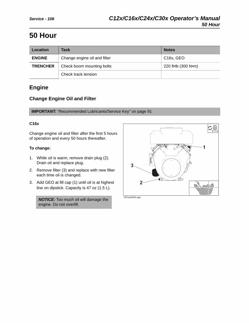
Service - 106 C12x/C16x/C24x/C30x Operator’s Manual50 Hour
50 Hour
Engine
Change Engine Oil and Filter
C16x
Change engine oil and filter after the first 5 hours of operation and every 50 hours thereafter.
To change:
1. While oil is warm, remove drain plug (2). Drain oil and replace plug.
2. Remove filter (3) and replace with new filter each time oil is changed.
3. Add GEO at fill cap (1) until oil is at highest line on dipstick. Capacity is 47 oz (1.5 L).
Location Task Notes
ENGINE Change engine oil and filter C16x, GEO
TRENCHER Check boom mounting bolts 220 ft•lb (300 N•m)
Check track tension
IMPORTANT: “Recommended Lubricants/Service Key” on page 91
NOTICE: Too much oil will damage the engine. Do not overfill.
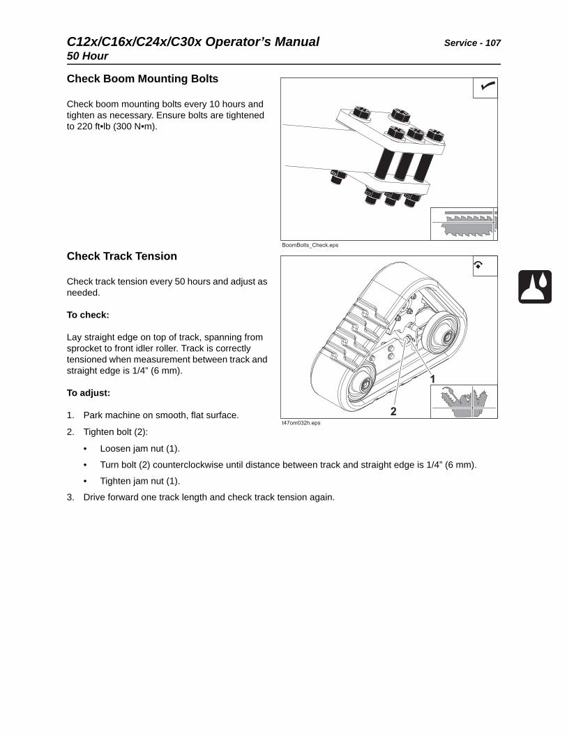
C12x/C16x/C24x/C30x Operator’s Manual Service - 107
50 Hour
Check Boom Mounting Bolts
Check boom mounting bolts every 10 hours and tighten as necessary. Ensure bolts are tightened to 220 ft•lb (300 N•m).
Check Track Tension
Check track tension every 50 hours and adjust as needed.
To check:
Lay straight edge on top of track, spanning from sprocket to front idler roller. Track is correctly tensioned when measurement between track and straight edge is 1/4” (6 mm).
To adjust:
1. Park machine on smooth, flat surface.
2. Tighten bolt (2):
• Loosen jam nut (1).
• Turn bolt (2) counterclockwise until distance between track and straight edge is 1/4” (6 mm).
• Tighten jam nut (1).
3. Drive forward one track length and check track tension again.
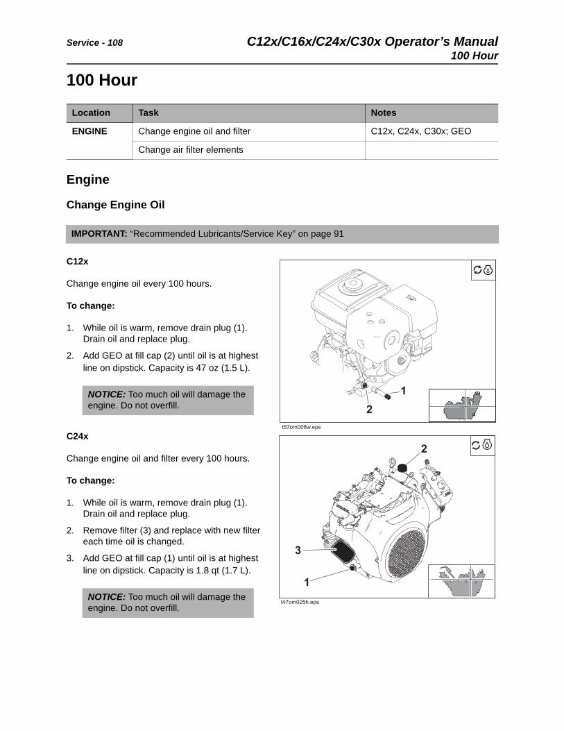
Service - 108 C12x/C16x/C24x/C30x Operator’s Manual100 Hour
100 Hour
Engine
Change Engine Oil
C12x
Change engine oil every 100 hours.
To change:
1. While oil is warm, remove drain plug (1). Drain oil and replace plug.
2. Add GEO at fill cap (2) until oil is at highest line on dipstick. Capacity is 47 oz (1.5 L).
C24x
Change engine oil and filter every 100 hours.
To change:
1. While oil is warm, remove drain plug (1). Drain oil and replace plug.
2. Remove filter (3) and replace with new filter each time oil is changed.
3. Add GEO at fill cap (1) until oil is at highest line on dipstick. Capacity is 1.8 qt (1.7 L).
Location Task Notes
ENGINE Change engine oil and filter C12x, C24x, C30x; GEO
Change air filter elements
IMPORTANT: “Recommended Lubricants/Service Key” on page 91
NOTICE: Too much oil will damage the engine. Do not overfill.
NOTICE: Too much oil will damage the engine. Do not overfill.
t57om008w.eps
3

C12x/C16x/C24x/C30x Operator’s Manual Service - 109
100 Hour
C30x
Change engine oil and filter every 100 hours.
To change:
1. While oil is warm, remove drain plug (1). Drain oil and replace plug.
2. Remove filter (3) and replace with new filter each time oil is changed.
3. Add GEO at fill cap (2) until oil is at highest line on dipstick. Capacity is 78 oz (2.3 L).
Change Air Filter Elements
C12x
Change air filter every 100 hours.
To change:
1. Remove wing nut (1) to remove air filter cover (2).
2. Remove wing nut (3) to remove primary (4) and secondary (2) filter elements.
3. Wipe inside of housing and wash cover.
4. Insert new secondary element and ensure it is seated correctly.
5. Insert new primary element.
6. Replace wing nut.
7. Replace cover and secure with wing nut. If cover does not fit, element is not properly locked into housing. Remove cover and primary element and repeat step 6.
NOTICE: Too much oil will damage the engine. Do not overfill.
NOTICE: Change the elements. Do not attempt to clean them.
• Compressed air or water may damage filter elements.
• Tapping filter elements to loosen dirt may damage the elements.
3
t57om012w.eps
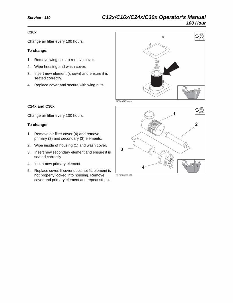
Service - 110 C12x/C16x/C24x/C30x Operator’s Manual100 Hour
C16x
Change air filter every 100 hours.
To change:
1. Remove wing nuts to remove cover.
2. Wipe housing and wash cover.
3. Insert new element (shown) and ensure it is seated correctly.
4. Replace cover and secure with wing nuts.
C24x and C30x
Change air filter every 100 hours.
To change:
1. Remove air filter cover (4) and remove primary (2) and secondary (3) elements.
2. Wipe inside of housing (1) and wash cover.
3. Insert new secondary element and ensure it is seated correctly.
4. Insert new primary element.
5. Replace cover. If cover does not fit, element is not properly locked into housing. Remove cover and primary element and repeat step 4.
1
2
3
4
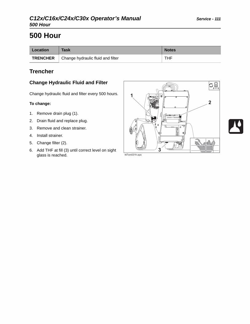
C12x/C16x/C24x/C30x Operator’s Manual Service - 111
500 Hour
500 Hour
Trencher
Change Hydraulic Fluid and Filter
Change hydraulic fluid and filter every 500 hours.
To change:
1. Remove drain plug (1).
2. Drain fluid and replace plug.
3. Remove and clean strainer.
4. Install strainer.
5. Change filter (2).
6. Add THF at fill (3) until correct level on sight glass is reached.
Location Task Notes
TRENCHER Change hydraulic fluid and filter THF
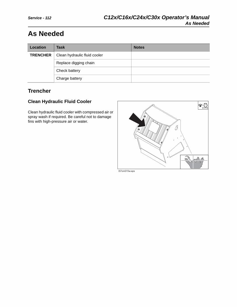
Service - 112 C12x/C16x/C24x/C30x Operator’s ManualAs Needed
As Needed
Trencher
Clean Hydraulic Fluid Cooler
Clean hydraulic fluid cooler with compressed air or spray wash if required. Be careful not to damage fins with high-pressure air or water.
Location Task Notes
TRENCHER Clean hydraulic fluid cooler
Replace digging chain
Check battery
Charge battery
t57om015w.eps
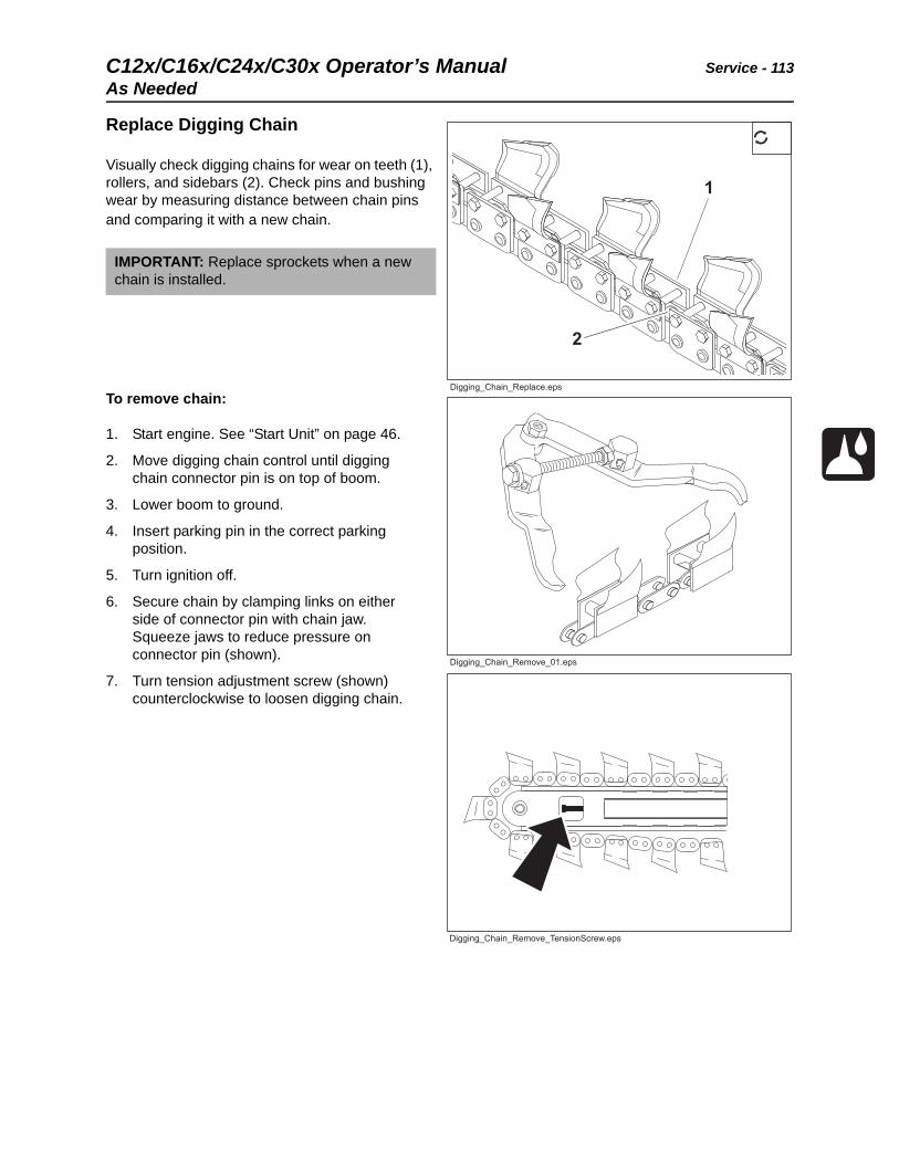
C12x/C16x/C24x/C30x Operator’s Manual Service - 113
As Needed
Replace Digging Chain
Visually check digging chains for wear on teeth (1), rollers, and sidebars (2). Check pins and bushing wear by measuring distance between chain pins and comparing it with a new chain.
To remove chain:
1. Start engine. See “Start Unit” on page 46.
2. Move digging chain control until digging chain connector pin is on top of boom.
3. Lower boom to ground.
4. Insert parking pin in the correct parking position.
5. Turn ignition off.
6. Secure chain by clamping links on either side of connector pin with chain jaw. Squeeze jaws to reduce pressure on connector pin (shown).
7. Turn tension adjustment screw (shown) counterclockwise to loosen digging chain.
IMPORTANT: Replace sprockets when a new chain is installed.
Digging_Chain_Remove_TensionScrew.eps
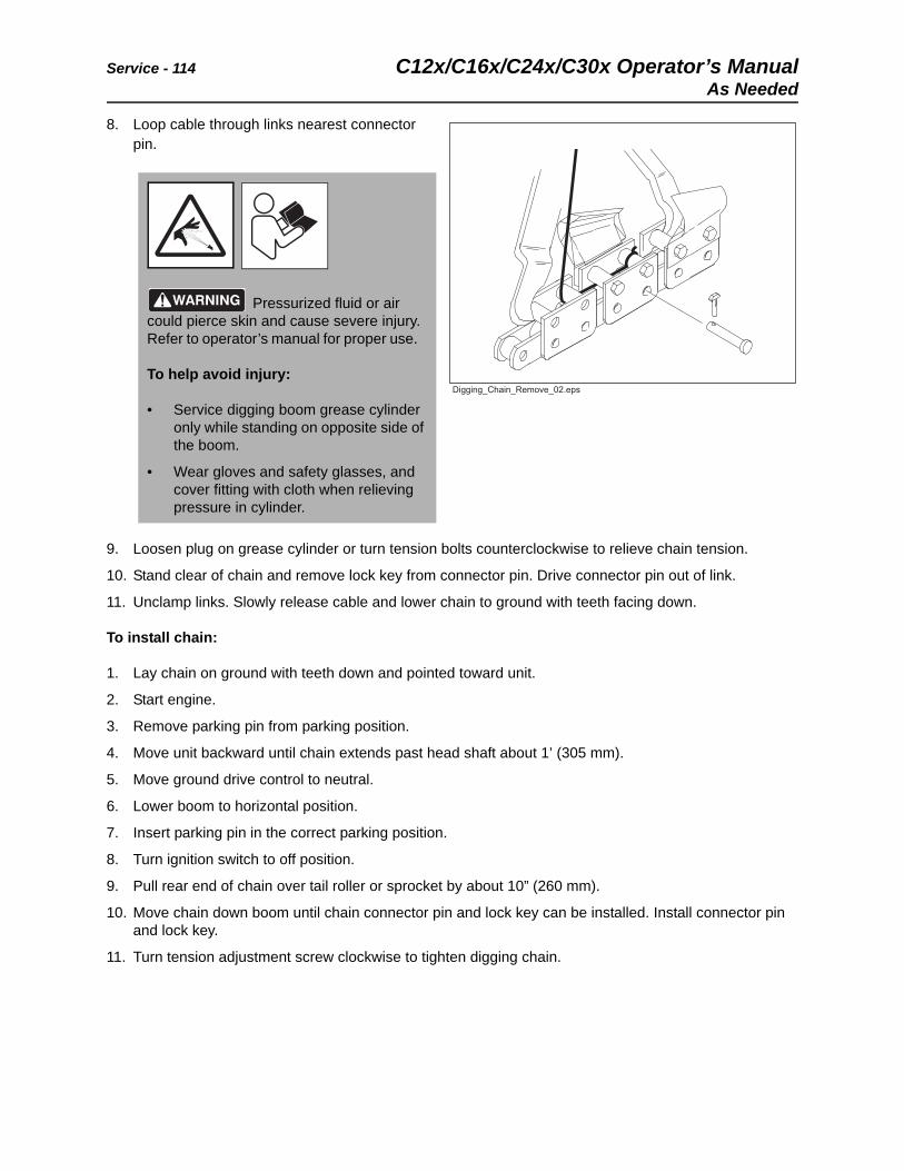
Service - 114 C12x/C16x/C24x/C30x Operator’s ManualAs Needed
8. Loop cable through links nearest connector pin.
9. Loosen plug on grease cylinder or turn tension bolts counterclockwise to relieve chain tension.
10. Stand clear of chain and remove lock key from connector pin. Drive connector pin out of link.
11. Unclamp links. Slowly release cable and lower chain to ground with teeth facing down.
To install chain:
1. Lay chain on ground with teeth down and pointed toward unit.
2. Start engine.
3. Remove parking pin from parking position.
4. Move unit backward until chain extends past head shaft about 1’ (305 mm).
5. Move ground drive control to neutral.
6. Lower boom to horizontal position.
7. Insert parking pin in the correct parking position.
8. Turn ignition switch to off position.
9. Pull rear end of chain over tail roller or sprocket by about 10” (260 mm).
10. Move chain down boom until chain connector pin and lock key can be installed. Install connector pin and lock key.
11. Turn tension adjustment screw clockwise to tighten digging chain.
Pressurized fluid or air could pierce skin and cause severe injury. Refer to operator’s manual for proper use.
To help avoid injury:
• Service digging boom grease cylinder only while standing on opposite side of the boom.
• Wear gloves and safety glasses, and cover fitting with cloth when relieving pressure in cylinder.
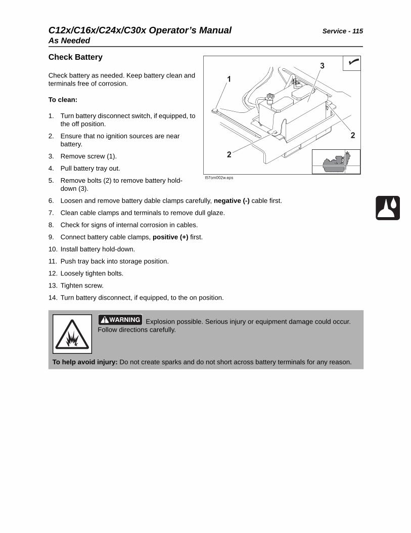
C12x/C16x/C24x/C30x Operator’s Manual Service - 115
As Needed
Check Battery
Check battery as needed. Keep battery clean and terminals free of corrosion.
To clean:
1. Turn battery disconnect switch, if equipped, to the off position.
2. Ensure that no ignition sources are near battery.
3. Remove screw (1).
4. Pull battery tray out.
5. Remove bolts (2) to remove battery hold-down (3).
6. Loosen and remove battery dable clamps carefully, negative (-) cable first.
7. Clean cable clamps and terminals to remove dull glaze.
8. Check for signs of internal corrosion in cables.
9. Connect battery cable clamps, positive (+) first.
10. Install battery hold-down.
11. Push tray back into storage position.
12. Loosely tighten bolts.
13. Tighten screw.
14. Turn battery disconnect, if equipped, to the on position.
Explosion possible. Serious injury or equipment damage could occur. Follow directions carefully.
To help avoid injury: Do not create sparks and do not short across battery terminals for any reason.
t57om002w.eps
1
2
2
3
Service - 116 C12x/C16x/C24x/C30x Operator’s ManualAs Needed
Charge Battery
Before You Start
Electronic components can be easily damaged by electrical surges. Jump starting can damage electronics and electrical systems, and is not recommended. Try to charge the battery instead. Use quality large diameter jumper cables capable of carrying high currents (400 amps or more). Cheap cables may not allow enough current flow to charge a dead/discharged battery.
Read all steps thoroughly and review illustration before performing procedure.
Explosion possible. Serious injury or equipment damage could occur. Follow directions carefully.
To help avoid injury:
• Use a single 12V maximum source for charging. Do not connect to rapid chargers or dual batteries.
• Use caution and wear personal protective equipment such as safety eyewear, when charging or cleaning battery.
• Keep sparks, flames, and any ignition sources away from batteries at all times. Internal contents are extremely hazardous. Leaking fluid is corrosive. Battery may be explosive at higher temperatures.
• NEVER lean over battery when making connections.
• Do not allow vehicles to touch when charging.
• Do not attempt to charge a battery that is leaking, bulging, heavily corroded, frozen, or otherwise damaged.
• NEVER short-circuit battery terminals for any reason or strike battery posts or cable terminals.
• Refer to MSDS for additional information regarding this battery.
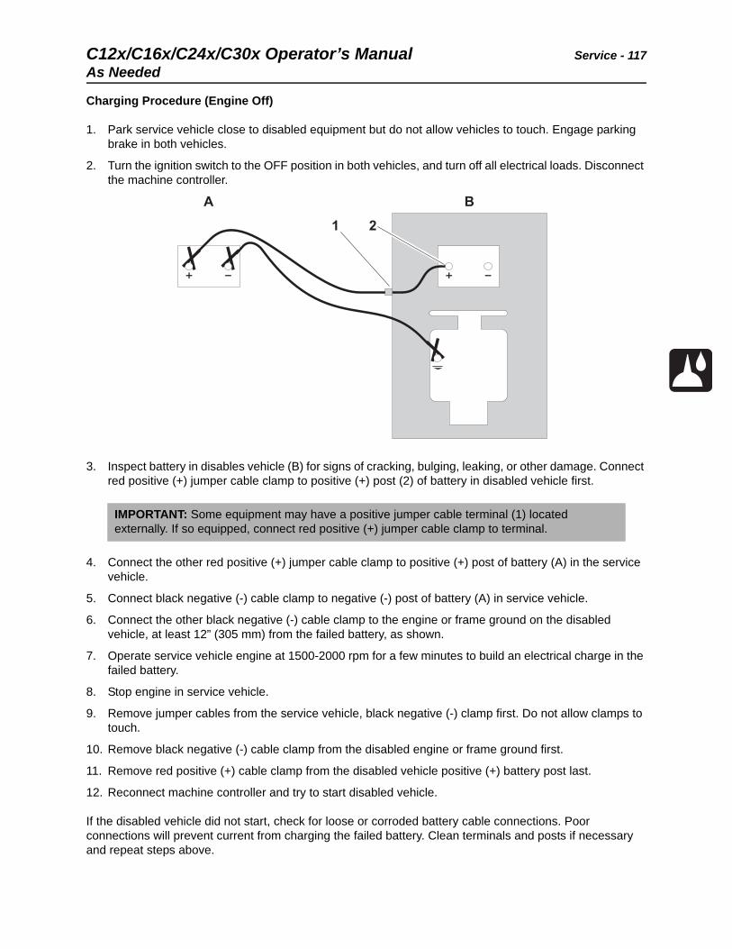
C12x/C16x/C24x/C30x Operator’s Manual Service - 117
As Needed
Charging Procedure (Engine Off)
1. Park service vehicle close to disabled equipment but do not allow vehicles to touch. Engage parking brake in both vehicles.
2. Turn the ignition switch to the OFF position in both vehicles, and turn off all electrical loads. Disconnect the machine controller.
3. Inspect battery in disables vehicle (B) for signs of cracking, bulging, leaking, or other damage. Connect red positive (+) jumper cable clamp to positive (+) post (2) of battery in disabled vehicle first.
4. Connect the other red positive (+) jumper cable clamp to positive (+) post of battery (A) in the service vehicle.
5. Connect black negative (-) cable clamp to negative (-) post of battery (A) in service vehicle.
6. Connect the other black negative (-) cable clamp to the engine or frame ground on the disabled vehicle, at least 12” (305 mm) from the failed battery, as shown.
7. Operate service vehicle engine at 1500-2000 rpm for a few minutes to build an electrical charge in the failed battery.
8. Stop engine in service vehicle.
9. Remove jumper cables from the service vehicle, black negative (-) clamp first. Do not allow clamps to touch.
10. Remove black negative (-) cable clamp from the disabled engine or frame ground first.
11. Remove red positive (+) cable clamp from the disabled vehicle positive (+) battery post last.
12. Reconnect machine controller and try to start disabled vehicle.
If the disabled vehicle did not start, check for loose or corroded battery cable connections. Poor connections will prevent current from charging the failed battery. Clean terminals and posts if necessary and repeat steps above.
IMPORTANT: Some equipment may have a positive jumper cable terminal (1) located externally. If so equipped, connect red positive (+) jumper cable clamp to terminal.

Service - 118 C12x/C16x/C24x/C30x Operator’s ManualAs Needed
C12x/C16x/C24x/C30x Operator’s Manual Specifications - 119
Specifications
Chapter Contents
C12x . . . . . . . . . . . . . . . . . . . . . . . . . . . . . . . . . . . . 120
C16x . . . . . . . . . . . . . . . . . . . . . . . . . . . . . . . . . . . . 123
C24x . . . . . . . . . . . . . . . . . . . . . . . . . . . . . . . . . . . . 126
C30x . . . . . . . . . . . . . . . . . . . . . . . . . . . . . . . . . . . . 129
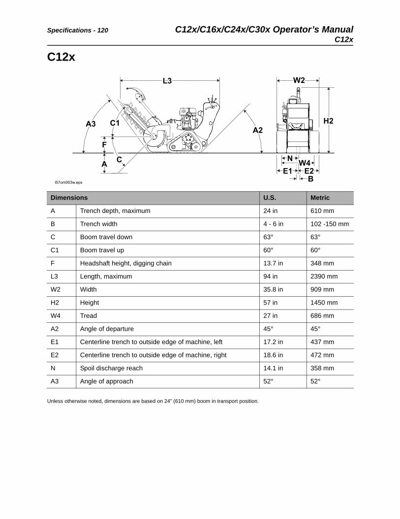
Specifications - 120 C12x/C16x/C24x/C30x Operator’s ManualC12x
C12x
Unless otherwise noted, dimensions are based on 24” (610 mm) boom in transport position.
Dimensions U.S. Metric
A Trench depth, maximum 24 in 610 mm
B Trench width 4 - 6 in 102 -150 mm
C Boom travel down 63° 63°
C1 Boom travel up 60° 60°
F Headshaft height, digging chain 13.7 in 348 mm
L3 Length, maximum 94 in 2390 mm
W2 Width 35.8 in 909 mm
H2 Height 57 in 1450 mm
W4 Tread 27 in 686 mm
A2 Angle of departure 45° 45°
E1 Centerline trench to outside edge of machine, left 17.2 in 437 mm
E2 Centerline trench to outside edge of machine, right 18.6 in 472 mm
N Spoil discharge reach 14.1 in 358 mm
A3 Angle of approach 52° 52°
t57om003w.eps
A3A3 C1C1
L3L3
A2A2
W2W2
H2H2
NN W4W4E1E1 E2E2
BB
CC
FF
AA
C12x/C16x/C24x/C30x Operator’s Manual Specifications - 121
C12x
Operational U.S. Metric
Vehicle speeds
Maximum transit forward 120 fpm 36.6 m/min
Maximum transit reverse 120 fpm 36.6 m/min
Digging chain speed
35K 253 fpm 77 m/min
Spoils handling (single, open-end auger):
Outer diameter 17 in 432 mm
Maximum operating weight 1360 lb 617 kg
Power U.S. Metric
Engine: Honda iGX390®
Fuel: gasoline
Cooling medium: air
Number of cylinders: one
Displacement 23.7 in3 389 cm3
Bore 3.5 in 88 mm
Stroke 2.5 in 64 mm
Manufacturer’s net power rating @ 3600 rpm (SAE J1940) 11.7 hp 8.7 kW
Rated speed 3600 rpm 3600 rpm
Fuel consumption 0.92 gph 3.5 L/h
Maximum tilt angle* 20° 20°
*Exceeding these operational angles will cause engine damage. This DOES NOT IMPLY machine is stable to maximum angle of safe engine operation.
Specifications - 122 C12x/C16x/C24x/C30x Operator’s ManualC12x
Power Train U.S. Metric
Hydraulic ground drive: infinitely variable from zero to maximum, speed and direction controlled with dual levers
Digging chain drive: hydraulic direct drive, lever-operated, one speed forward and reverse
Trencher drive: hydraulic direct drive
Pump drive: direct drive from engine
Spoils handling drive: mechanical, attached to and rotates with headshaft
Track
Width 200 mm 200 mm
Ground pressure 3.3 psi 23 kPa
Hydraulic System U.S. Metric
Dual pump total capacity @ 3600 rpm 7.5 gpm 28.4 L/min
Pump characteristics @ 3600 rpm to ground drive:
Pressure, relief valve setting 2500 psi 172 bar
Capacity 1.5 gpm 5.7 L/min
Pump characteristics @ 3600 rpm to digging drive:
Pressure, relief valve setting 3500 psi 241 bar
Capacity 6 gpm 22.7 L/min
Fluid Capacities U.S. Metric
Hydraulic reservoir 11 gal 41.6 L
Hydraulic system 11.5 gal 43.5 L
Fuel tank 1.6 gal 6.05 L
Engine oil 1.2 qt 1.1 L
Noise Levels
This machine can generate sound levels exceeding 80 dBA. Always wear appropriate hearing protection when operating machine. Find sound power and pressure information at www.ditchwitch.com, or contact [email protected].
Vibration Levels
Vibration at the operator’s hand during normal operation is less than 2.5 m/s2
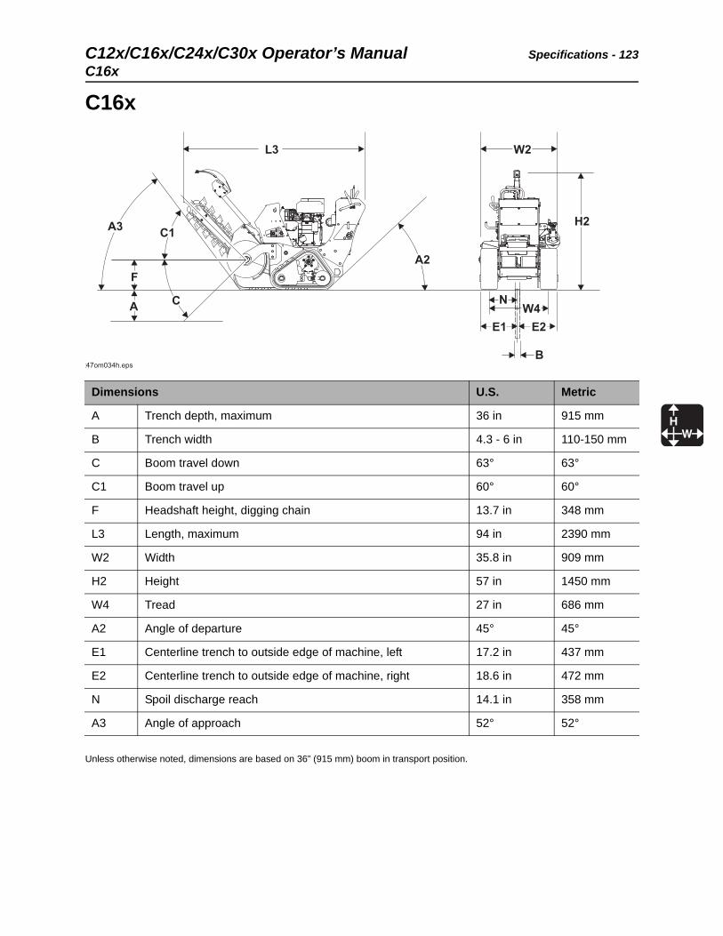
C12x/C16x/C24x/C30x Operator’s Manual Specifications - 123
C16x
C16x
Unless otherwise noted, dimensions are based on 36” (915 mm) boom in transport position.
Dimensions U.S. Metric
A Trench depth, maximum 36 in 915 mm
B Trench width 4.3 - 6 in 110-150 mm
C Boom travel down 63° 63°
C1 Boom travel up 60° 60°
F Headshaft height, digging chain 13.7 in 348 mm
L3 Length, maximum 94 in 2390 mm
W2 Width 35.8 in 909 mm
H2 Height 57 in 1450 mm
W4 Tread 27 in 686 mm
A2 Angle of departure 45° 45°
E1 Centerline trench to outside edge of machine, left 17.2 in 437 mm
E2 Centerline trench to outside edge of machine, right 18.6 in 472 mm
N Spoil discharge reach 14.1 in 358 mm
A3 Angle of approach 52° 52°
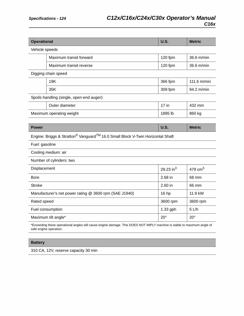
Specifications - 124 C12x/C16x/C24x/C30x Operator’s ManualC16x
Operational U.S. Metric
Vehicle speeds
Maximum transit forward 120 fpm 36.6 m/min
Maximum transit reverse 120 fpm 36.6 m/min
Digging chain speed
19K 366 fpm 111.6 m/min
35K 309 fpm 94.2 m/min
Spoils handling (single, open-end auger):
Outer diameter 17 in 432 mm
Maximum operating weight 1895 lb 860 kg
Power U.S. Metric
Engine: Briggs & Stratton® VanguardTM 16.0 Small Block V-Twin Horizontal Shaft
Fuel: gasoline
Cooling medium: air
Number of cylinders: two
Displacement 29.23 in3 479 cm3
Bore 2.68 in 68 mm
Stroke 2.60 in 66 mm
Manufacturer’s net power rating @ 3600 rpm (SAE J1940) 16 hp 11.9 kW
Rated speed 3600 rpm 3600 rpm
Fuel consumption 1.33 gph 5 L/h
Maximum tilt angle* 20° 20°
*Exceeding these operational angles will cause engine damage. This DOES NOT IMPLY machine is stable to maximum angle of safe engine operation.
Battery
310 CA, 12V, reserve capacity 30 min

C12x/C16x/C24x/C30x Operator’s Manual Specifications - 125
C16x
Power Train U.S. Metric
Hydraulic ground drive: infinitely variable from zero to maximum, speed and direction controlled with dual levers
Digging chain drive: hydraulic direct drive, lever-operated, one speed forward and reverse
Trencher drive: hydraulic direct drive
Pump drive: direct drive from engine
Spoils handling drive: mechanical, attached to and rotates with headshaft
Track
Width 200 mm 200 mm
Ground pressure 4.5 psi 31 kPa
Hydraulic System U.S. Metric
Dual pump total capacity @ 3600 rpm 11.5 gpm 43.5 L/min
Pump characteristics @ 3600 rpm to ground drive:
Pressure, relief valve setting 2200 psi 152 bar
Capacity 1.5 gpm 5.7 L/min
Pump characteristics @ 3600 rpm to digging drive:
Pressure, relief valve setting 3500 psi 241 bar
Capacity 10 gpm 37.9 L/min
Fluid Capacities U.S. Metric
Hydraulic reservoir 11 gal 41.6 L
Hydraulic system 11.5 gal 43.5 L
Fuel tank 2.3 gal 6.5 L
Engine oil 47 oz 1.47 L
Noise Levels
This machine can generate sound levels exceeding 80 dBA. Always wear appropriate hearing protection when operating machine. Find sound power and pressure information at www.ditchwitch.com, or contact [email protected].
Vibration Levels
Vibration at the operator’s hand during normal operation is less than 2.5 m/s2
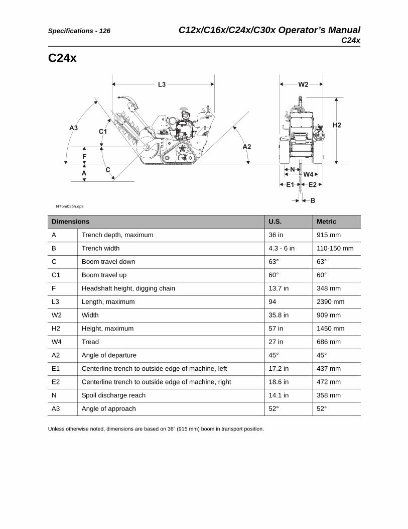
Specifications - 126 C12x/C16x/C24x/C30x Operator’s ManualC24x
C24x
Unless otherwise noted, dimensions are based on 36” (915 mm) boom in transport position.
Dimensions U.S. Metric
A Trench depth, maximum 36 in 915 mm
B Trench width 4.3 - 6 in 110-150 mm
C Boom travel down 63° 63°
C1 Boom travel up 60° 60°
F Headshaft height, digging chain 13.7 in 348 mm
L3 Length, maximum 94 2390 mm
W2 Width 35.8 in 909 mm
H2 Height, maximum 57 in 1450 mm
W4 Tread 27 in 686 mm
A2 Angle of departure 45° 45°
E1 Centerline trench to outside edge of machine, left 17.2 in 437 mm
E2 Centerline trench to outside edge of machine, right 18.6 in 472 mm
N Spoil discharge reach 14.1 in 358 mm
A3 Angle of approach 52° 52°
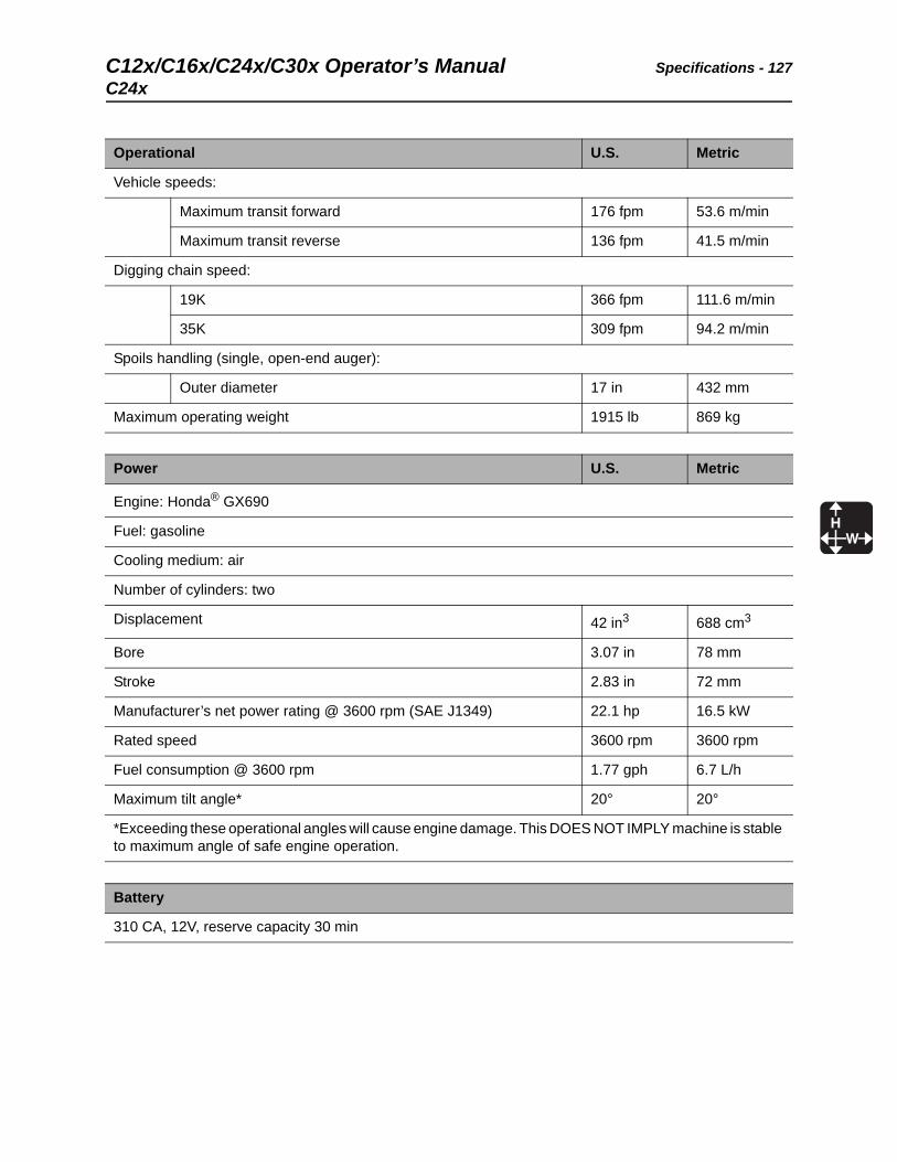
C12x/C16x/C24x/C30x Operator’s Manual Specifications - 127
C24x
Operational U.S. Metric
Vehicle speeds:
Maximum transit forward 176 fpm 53.6 m/min
Maximum transit reverse 136 fpm 41.5 m/min
Digging chain speed:
19K 366 fpm 111.6 m/min
35K 309 fpm 94.2 m/min
Spoils handling (single, open-end auger):
Outer diameter 17 in 432 mm
Maximum operating weight 1915 lb 869 kg
Power U.S. Metric
Engine: Honda® GX690
Fuel: gasoline
Cooling medium: air
Number of cylinders: two
Displacement 42 in3 688 cm3
Bore 3.07 in 78 mm
Stroke 2.83 in 72 mm
Manufacturer’s net power rating @ 3600 rpm (SAE J1349) 22.1 hp 16.5 kW
Rated speed 3600 rpm 3600 rpm
Fuel consumption @ 3600 rpm 1.77 gph 6.7 L/h
Maximum tilt angle* 20° 20°
*Exceeding these operational angles will cause engine damage. This DOES NOT IMPLY machine is stable to maximum angle of safe engine operation.
Battery
310 CA, 12V, reserve capacity 30 min

Specifications - 128 C12x/C16x/C24x/C30x Operator’s ManualC24x
Power Train U.S. Metric
Hydraulic ground drive: infinitely variable from zero to maximum, speed and direction controlled with dual levers
Digging chain drive: hydraulic direct drive, lever-operated, one speed forward and reverse
Trencher drive: hydraulic direct drive
Pump drive: direct drive from engine
Spoils handling drive: mechanical, attached to and rotates with headshaft
Track
Width 200 mm 200 mm
Ground pressure 4.5 psi 31 kPa
Hydraulic System U.S. Metric
Dual pump total capacity @ 3600 rpm 13 gpm 49.2 L/min
Pump characteristics @ 3600 rpm to ground drive:
Pressure, relief valve setting 2500 psi 172 bar
Capacity 3 gpm 11.4 L/min
Pump characteristics @ 3600 rpm to digging drive:
Pressure, relief valve setting 3500 psi 241 bar
Capacity 10 gpm 37.9 L/min
Fluid Capacities U.S. Metric
Hydraulic reservoir 11 gal 41.6 L
Hydraulic system 11.5 gal 43.5 L
Fuel tank 6 gal 22.7 L
Engine oil 1.8 qt 1.7 L
Noise Levels
This machine can generate sound levels exceeding 80 dBA. Always wear appropriate hearing protection when operating machine. Find sound power and pressure information at www.ditchwitch.com, or contact [email protected].
Vibration Levels
Vibration at the operator’s hand during normal operation is less than 2.5 m/s2
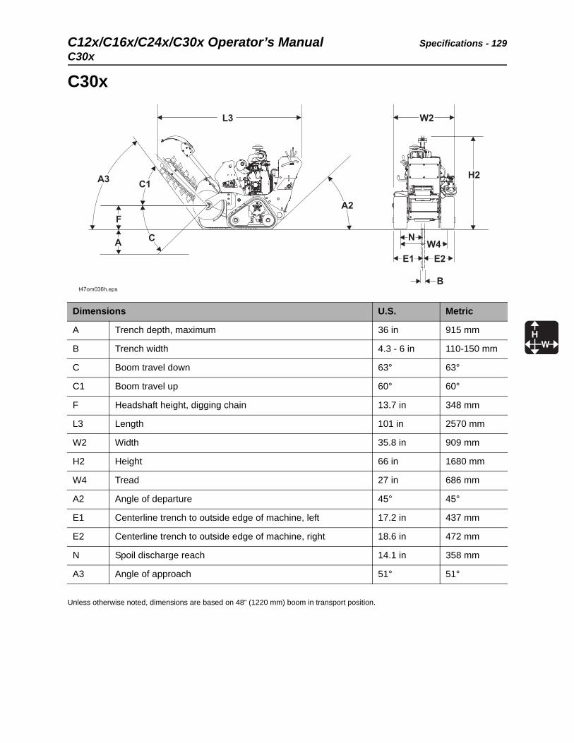
C12x/C16x/C24x/C30x Operator’s Manual Specifications - 129
C30x
C30x
Unless otherwise noted, dimensions are based on 48” (1220 mm) boom in transport position.
Dimensions U.S. Metric
A Trench depth, maximum 36 in 915 mm
B Trench width 4.3 - 6 in 110-150 mm
C Boom travel down 63° 63°
C1 Boom travel up 60° 60°
F Headshaft height, digging chain 13.7 in 348 mm
L3 Length 101 in 2570 mm
W2 Width 35.8 in 909 mm
H2 Height 66 in 1680 mm
W4 Tread 27 in 686 mm
A2 Angle of departure 45° 45°
E1 Centerline trench to outside edge of machine, left 17.2 in 437 mm
E2 Centerline trench to outside edge of machine, right 18.6 in 472 mm
N Spoil discharge reach 14.1 in 358 mm
A3 Angle of approach 51° 51°
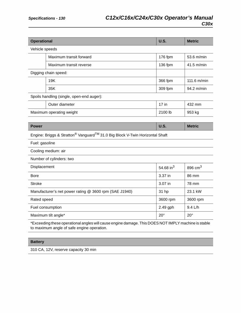
Specifications - 130 C12x/C16x/C24x/C30x Operator’s ManualC30x
Operational U.S. Metric
Vehicle speeds
Maximum transit forward 176 fpm 53.6 m/min
Maximum transit reverse 136 fpm 41.5 m/min
Digging chain speed:
19K 366 fpm 111.6 m/min
35K 309 fpm 94.2 m/min
Spoils handling (single, open-end auger):
Outer diameter 17 in 432 mm
Maximum operating weight 2100 lb 953 kg
Power U.S. Metric
Engine: Briggs & Stratton® VanguardTM 31.0 Big Block V-Twin Horizontal Shaft
Fuel: gasoline
Cooling medium: air
Number of cylinders: two
Displacement 54.68 in3 896 cm3
Bore 3.37 in 86 mm
Stroke 3.07 in 78 mm
Manufacturer’s net power rating @ 3600 rpm (SAE J1940) 31 hp 23.1 kW
Rated speed 3600 rpm 3600 rpm
Fuel consumption 2.49 gph 9.4 L/h
Maximum tilt angle* 20° 20°
*Exceeding these operational angles will cause engine damage. This DOES NOT IMPLY machine is stable to maximum angle of safe engine operation.
Battery
310 CA, 12V, reserve capacity 30 min
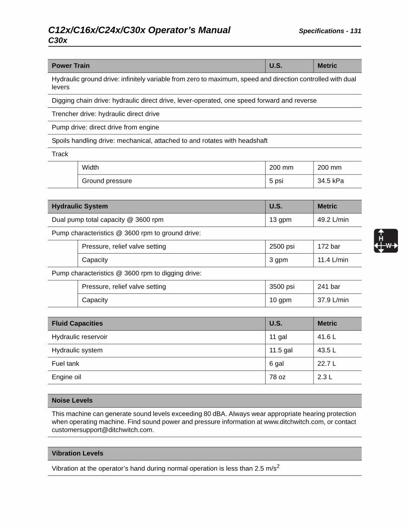
C12x/C16x/C24x/C30x Operator’s Manual Specifications - 131
C30x
Power Train U.S. Metric
Hydraulic ground drive: infinitely variable from zero to maximum, speed and direction controlled with dual levers
Digging chain drive: hydraulic direct drive, lever-operated, one speed forward and reverse
Trencher drive: hydraulic direct drive
Pump drive: direct drive from engine
Spoils handling drive: mechanical, attached to and rotates with headshaft
Track
Width 200 mm 200 mm
Ground pressure 5 psi 34.5 kPa
Hydraulic System U.S. Metric
Dual pump total capacity @ 3600 rpm 13 gpm 49.2 L/min
Pump characteristics @ 3600 rpm to ground drive:
Pressure, relief valve setting 2500 psi 172 bar
Capacity 3 gpm 11.4 L/min
Pump characteristics @ 3600 rpm to digging drive:
Pressure, relief valve setting 3500 psi 241 bar
Capacity 10 gpm 37.9 L/min
Fluid Capacities U.S. Metric
Hydraulic reservoir 11 gal 41.6 L
Hydraulic system 11.5 gal 43.5 L
Fuel tank 6 gal 22.7 L
Engine oil 78 oz 2.3 L
Noise Levels
This machine can generate sound levels exceeding 80 dBA. Always wear appropriate hearing protection when operating machine. Find sound power and pressure information at www.ditchwitch.com, or contact [email protected].
Vibration Levels
Vibration at the operator’s hand during normal operation is less than 2.5 m/s2

Specifications - 132 C12x/C16x/C24x/C30x Operator’s ManualC30x
C12x/C16x/C24x/C30x Operator’s Manual Support - 133
Procedure
Support
Procedure
Notify your dealer immediately of any malfunction or failure of Ditch Witch® equipment.
Always give model, serial number, and approximate date of your equipment purchase. This information should be recorded and placed on file by the owner at the time of purchase.
Return damaged parts to dealer for inspection and warranty consideration if in warranty time frame.
Order genuine Ditch Witch replacement or repair parts from your authorized Ditch Witch dealer. Use of another manufacturer's parts may void warranty consideration.
Resources
Publications
Contact your Ditch Witch dealer for publications and videos covering safety, operation, service, and repair of your equipment.
Ditch Witch® Training
For information about on-site, individualized training, contact your Ditch Witch dealer.
Warranty - 134 C12x/C16x/C24x/C30x Operator’s Manual
Warranty
Ditch Witch® Equipment and Replacement PartsLimited Warranty Policy
Subject to the limitation and exclusions herein, free replacement parts will be provided at any authorized Ditch Witch dealership for any Ditch Witch equipment or parts manufactured by the Ditch Witch factory that fail due to a defect in material or workmanship within one (1) year of first commercial use. Free labor will be provided at any authorized Ditch Witch dealership for installation of parts under this warranty during the first year following “initial commercial” use of the serial-numbered Ditch Witch equipment on which it is installed. The customer is responsible for transporting their equipment to an authorized Ditch Witch dealership for all warranty work.
Exclusions from Product Warranty• All incidental or consequential damages.
• All defects, damages, or injuries caused by misuse, abuse, improper installation, alteration, neglect, or uses other than those for which products were intended.
• All defects, damages, or injuries caused by improper training, operation, or servicing of products in a manner inconsistent with manufacturer’s recommendations.
• All engines and engine accessories (these are covered by original manufacturer’s warranty).
• Tires, belts, and other parts which may be subject to another manufacturer’s warranty (such warranty will be available to purchaser).
• ALL IMPLIED WARRANTIES NOT EXPRESSLY STATED HEREIN, INCLUDING ANY WARRANTY OF FITNESS FOR A PARTICULAR PURPOSE AND MERCHANTABILITY.
IF THE PRODUCTS ARE PURCHASED FOR COMMERCIAL PURPOSES, AS DEFINED BY THE UNIFORM COMMERCIAL CODE, THEN THERE ARE NO WARRANTIES WHICH EXTEND BEYOND THE FACE HEREOF AND THERE ARE NO IMPLIED WARRANTIES OF ANY KIND WHICH EXTEND TO A COMMERCIAL BUYER. ALL OTHER PROVISIONS OF THIS LIMITED WARRANTY APPLY INCLUDING THE DUTIES IMPOSED.
Ditch Witch products have been tested to deliver acceptable performance in most conditions. This does not imply they will deliver acceptable performance in all conditions. Therefore, to assure suitability, products should be operated under anticipated working conditions prior to purchase.
Defects will be determined by an inspection within thirty (30) days of the date of failure of the product or part by Ditch Witch Product Support (DWPS) or its authorized dealer. DWPS will provide the location of its inspection facilities or its nearest authorized dealer upon inquiry. DWPS reserves the right to supply remanufactured replacements parts under this warranty as it deems appropriate.
Extended warranties are available upon request from your local Ditch Witch dealer or the Ditch Witch factory.
Some states do not allow exclusion or limitation of incidental or consequential damages, so above limitation of exclusion may not apply. Further, some states do not allow exclusion of or limitation of how long an implied warranty lasts, so the above limitation may not apply. This limited warranty gives product owner specific legal rights and the product owner may also have other rights which vary from state to state.
For information regarding this limited warranty, contact the DWPS department, P.O. Box 66, Perry, OK 73077-0066, or contact your local dealer.
First version: 1/91; Latest version: 8/16
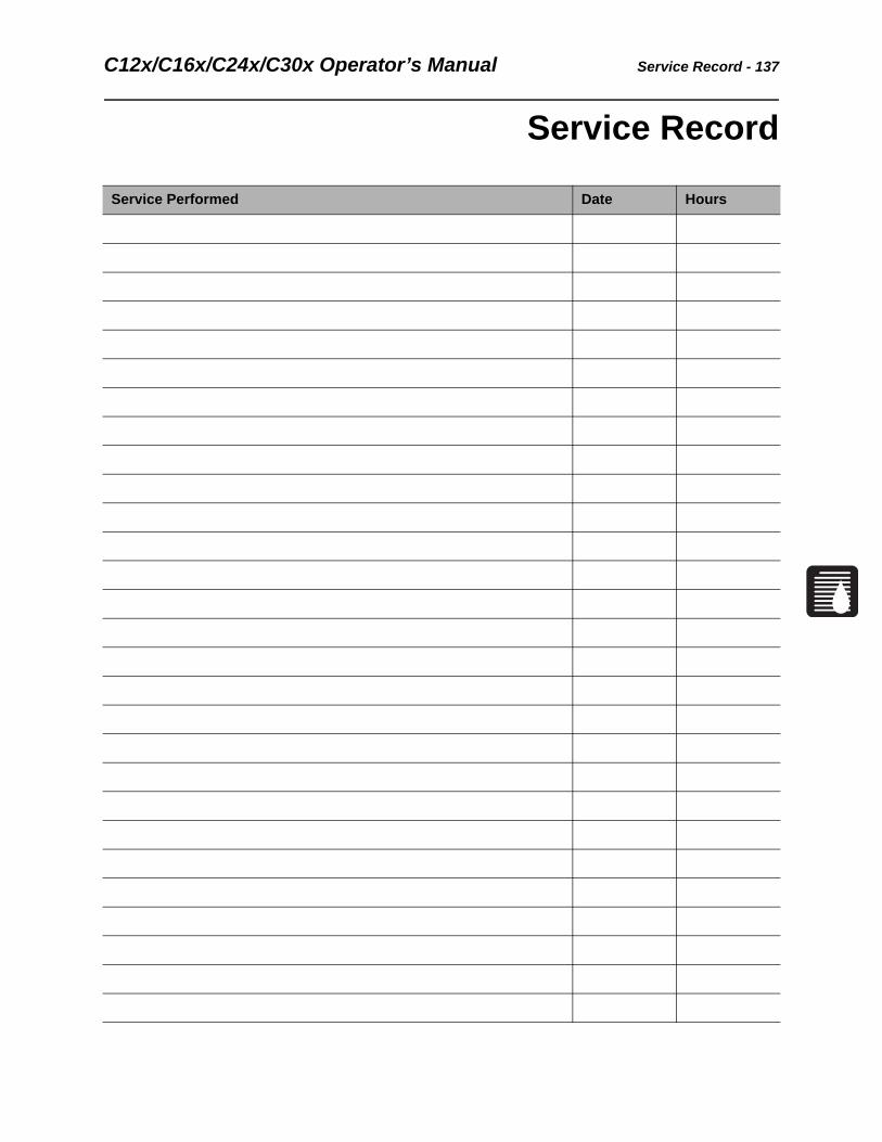
C12x/C16x/C24x/C30x Operator’s Manual Service Record - 137
Service Record
Service Performed Date Hours

Service Record - 138 C12x/C16x/C24x/C30x Operator’s Manual
Service Performed Date Hours


