owner’s / operator’s manual
TRANSCRIPT
OWNER’S / OPERATOR’S MANUAL
Read this manual carefully before operating this vehicle.
SUPER HAULER
J2F-F8199-11LIT-19626-A0-24
DR2E SUPER HAULER
UTILITY VEHICLE
2019MODEL YEAR
©2019 Yamaha Golf-Car Com
pany
©2019 Yamaha Golf-Car Com
pany

iJ2F
INTRODUCTIONCongratulations on your purchase of a Yamaha Personal Transport Vehicle (Super Hauler). This manual contains information you will need for proper operation, maintenance, and care of your Super Hauler. A thorough understanding of these simple instructions will help you to obtain maximum enjoyment from your new Yamaha.
If you have any questions about the operation or maintenance of your Super Hauler, please consult a Yamaha dealer.
Yamaha Golf-Car Company
DR2E SUPER HAULER
© 2019 by Yamaha Golf-Car Company1st edition
All rights reserved. Any reprinting or unauthorized use without the
written permission of Yamaha Golf-Car Company
is expressly prohibited. Printed in U.S.A. LIT-19626-A0-24
OWNER’S/OPERATOR’S MANUAL
©2019 Yamaha Golf-Car Com
pany

ii J2F
IMPORTANT MANUAL INFORMATION
Particularly important information is distinguished in this manual by the following notations:
This is the safety alert symbol. It is used to alert you to potential personal injury hazards. Obey all safety messages that follow this symbol to avoid possible injury or death.
A WARNING indicates a hazardous situation which, if not avoided, could result in death or serious injury.
NOTICEA NOTICE indicates special precautions that must be taken to avoid damage to the four-passenger vehicle or other property.
TIPA TIP provides key information to make procedures easier or clearer.
TIPYamaha continually seeks advancements in product design and quality; therefore, while this manual contains the most current product information available at the time of printing, there may be minor discrepancies between your vehicle and this manual. If you have any questions concerning this manual, please consult your Yamaha dealer.
Read and understand this manual completely before operating your vehicle. This manual should be considered a permanent part of your vehicle and should remain with the vehicle when resold.
©2019 Yamaha Golf-Car Com
pany

iiiJ2F
CONTENTS
1WARRANTY
2IMPORTANT LABELS
3OPERATOR SAFETY
4SAFETY CONSIDERATIONS
5CONTROLS
6PRE-OPERATION CHECKS
7OPERATION
8MAINTENANCE
9STORAGE
10SPECIFICATIONS
11WIRING
©2019 Yamaha Golf-Car Com
pany

1
1-1 J2F
WARRANTY
straPnommoCFrame
elxasnarTsladeP
)sdap/seohsgnidulcxe(sekarBsyalerdna,sehctiws,seriwlacirtcelE
stnenopmocgnireetS/noisnepsuSstaeS
poTnuSstraPydoB/srepmuB
staMroolFsredloHdracerocS
reirraCgaBCommon Accessories
dleihsdniWthgiL daeH
thgiL liaT
2 Years2 Years
2 Years2 Years2 Years2 Years2 Years2 Years2 Years2 Years2 Years2 Years
3 Years2 Years2 Years
2 Years
2 Years2 Years2 Years2 Years
2 Years2 Years2 Years1 Year2 Years
1 year
cificepS raC cirtcelE4 Years or 23,500 amp-hours
whichever comes first*Detailed condition on the next page
Battery - Trojan ' T875 ' withoutHydroLink Watering System
rotoMcirtcelE
regrahCdroCregrahC
elcatpeceRregrahCrosneSnoitisoPelttorhT
GAS Car specificrotareneG/ekatnI/tsuahxE
enignEsaGslortnoC/selbaCelttorhT
yrettaB)tlebevirdgnidulcxe(hctulC
straPgniniameRllA
2 Years
LIMITED 2-YEAR WARRANTY FOR TRANSPORTATION AND UTILITY VEHICLES
Yamaha Golf-Car Company hereby warrants that any new Yamaha utility vehicle or any multi passenger cars or specialty vehicles purchased from Yamaha, or an Authorized Dealer or Distributor in the United States will be free from defects in material and workmanship for TWO years from date of purchase, subject to the stated limitations. DURING THE PERIOD OF WARRANTY, any authorized Yamaha golf car service technician, dealer, or distributor will, free of charge, repair or replace, at Yamaha’s option, any part adjudged defective by Yamaha due to faulty workmanship or material from the factory. Parts used in warranty repairs will be warranted for the balance of the vehicle’s warranty period. All parts replaced under warranty becomeproperty of Yamaha Golf-Car Company.
EXCLUSIONS from this Warranty shall include any failures caused by:Abnormal strain, neglect, or abuse, including lack of proper maintenance, and use contrary to the Owner’s/Operator’sManual instructions.Accident or collision damage.Installation of parts or accessories that are not original equipment.Fading, rust, or deterioration due to exposure or ordinary wear and tear.Modifications or alterations that affect the car’s condition, operation, performance, or durability.Damage due to improper transportation.Acts of God, e.g. lightning, hail damage, flooding, fire, etc.
This Limited Warranty does not cover any parts replaced due to normal wear or routine maintenance, including oil and air filter elements, brake shoes, tire wear, spark plugs, starter and clutch drive belts. Any charges incurred in transporting a golf car or charger to and from an authorized Yamaha golf car dealer for service or in performing field service are also excluded from this warranty. Gasoline-powered golf car starting batteries on vehicles equipped with a golf course GPS device, or any other device with a parasitic current draw, unless the vehicle is equipped from the factory with an optional deep cycle starting battery, are also excluded from this warranty.
THE CUSTOMER’S RESPONSIBILITY under this warranty shall be to operate and maintain the golf car and charger as specified in the appropriate Owner’s/Operator’s Manual, and give notice to an authorized Yamaha golf car dealer of any and all apparent defects within ten (10) days after discovery, and make the vehicle or charger available at that time for inspection and repairs by the dealer’s authorized representative.
WARRANTY TRANSFER: This warranty is to the original owner only and is not transferable.
EFFECTIVE DATE: 5/1/17
rellortnoCrotoM
Yamaha Golf-Car Company makes no other warranty of any kind, expressed or implied. All implied warranties of merchantability and fitness of merchantability and fitness for a particular purpose which exceed the obligations and time limits stated in this warranty are hereby disclaimed by Yamaha Golf-Car Company and excluded from this Warranty.Some states do not allow limitations on how long implied warranty lasts, so the above limitation may not apply to you. Also excluded from this Warranty is any incidental or consequential damages including loss of use. Some states do not allow the exclusion or limitation of incidental or consequential damages, so the above exclusion may not apply to you.This Warranty give you specific legal rights, and you may also have other rights, which vary from state to state.
YAMAHA GOLF-CAR COMPANY, KENNESAW, GEORGIA 30144
©2019 Yamaha Golf-Car Com
pany
1
1-2J2F
WARRANTY
Yamaha Golf-Car Company (herein referred to as “YGC”) herebywarrants to the Original Retail Purchaser or Lessee of a YAMAHA TheDrive golf car or PTV, Adventurer utility vehicle, or YAMAHA Conciergetransportation or specialty car purchased from Yamaha, or anAuthorized Dealer or Distributor in the United States, that the Trojanbatteries charged with a YAMAHA battery charger will be free fromdefects in materials and workmanship, and will provide “36-holeperformance” as follows:
4-years or 23,500 amp-hours with T-8754-years or 25,000 amp-hours with T-875 batteries & the addition ofa factory-installed Trojan HydroLink Battery Watering System.
WARRANTY LIMITATIONSYamaha Golf-Car Company’s and Trojan Battery Company’s limit ofliability shall be to replace a defective battery. Replacement shallmean furnishing a new battery or used battery with sufficient life tocomplete the remainder of the warranty term, at no cost to thepurchaser during the limited warranty period, except for labor ortransportation expenses.
The following conditions apply:
Amp-hours will be determined either through the Genius controlleror through other means as necessary in the event of a controllerfailure or replacement.This warranty only applies to factory installed Trojan battery setscharged with a Yamaha battery charger.The customer must perform (or have a contracted Yamaha Dealerperform) all periodic maintenance and discharge testing asspecified in the Yamaha Service Manual Maintenance Schedule.No labor or transportation expenses are included in this limitedwarranty. Maintenance records must be kept.YGC supplied or approved replacement batteries may be of adifferent brand or capacity, but are warranted to provide 36-holeperformance for the remainder of the original warranty term.“36-hole performance” is defined as 60-minutes discharge time astested and recorded using a Lester model #17770 dischargemachine at an ambient temperature of between 60 and 100degrees F (16 and 38 degrees C). Ambient temperaturesbetween 60 and 80 degrees F (16 and 27 degrees C) must becorrected using the formula: Adjusted Discharge Time =(Discharge Minutes) / (1-(((80-TEMP)/100) x 0.64)).The customer must notify the Dealer within 10 days that a vehiclehas failed to make 36 holes per day. YGC reserves the right totest and recharge any battery in question.
ANY IMPLIED WARRANTY OF MERCHANTABILITY OR FITNESSFOR A PARTICULAR PURPOSE SHALL BE VOID AND EXCLUDEDSUBSEQUENT TO ONE YEAR FROM THE DATE OF PURCHASE.THE REPLACEMENT OF THE BATTERY IS THE EXCLUSIVEREMEDY UNDER THIS WRITTEN WARRANTY OR ANY IMPLIEDWARRANTY. YAMAHA MAKES NO OTHER REPRESENTATIONOR WARRANTY OF ANY KIND, AND NO REPRESENTATIVE,EMPLOYEE, DISTRIBUTOR OR DEALER OF YAMAHA HAS THEAUTHORITY TO MAKE OR IMPLY ANY REPRESENTATION,PROMISE OR AGREEMENT WHICH IN ANY WAY VARIES THETERMS OF THIS LIMITED WARRANTY.
LIMITED WARRANTY EXCLUSIONSWithout limiting the generality of the foregoing in any way, and aspart of its limited warranty exclusion, YAMAHA does not warrantthat its battery is suitable for use in any application other than in agolf car or utility vehicle. As in the use of any battery, a prudentowner will read and study the charger owner’s manual, the vehicleowner’s manual, the operator’s instructions, and the battery warninglabels; and will exercise due care in working on or around batteries.
THE PROVISIONS OF THIS LIMITED WARRANTY SHALLNOT APPLY IF BATTERIES ARE SUBJECTED TO ANY OFTHE FOLLOWING CONDITIONS:
Abuse or neglect such as improper fluid levels, loose wiring,rusted or corroded hardware.Lack of proper maintenance as outlined in the electric vehicleOwner’s/Operator’s Manual. For example, lack of regularbattery watering or adding water to the battery beforecharging.Damage caused by improper installation of the battery.Neglect, breakage, freezing, fire, explosion, wreckage, theaddition of any chemical, or the operation of the battery in anuncharged condition (below half-charge – 1.200 specificgravity).Battery charged by systems other than the original equipmenttype battery charger.On fleet golf cars, the use of any non-YAMAHA suppliedelectrical devices that consume more than one amp-hour perround or two amp-hours per day of battery energy. Examplesof these devices include, but are not limited to: heating orcooling systems; GPS (global position system) devices;information gathering devices; lights; radios or stereos; oryardage measuring devices.Less than one charger per car or inadequate facility electricalpower to power all chargers. Examples include more thanone charger on a single circuit, circuit rating of less than 15amps, or not enough circuits for the number of cars.In fleet applications, less than one battery charger per vehicle.For example, using only 10 battery chargers to charge a 15car fleet. The use of any system that does not allow the batterychargers to shut off automatically. For example, timersystems that are designed to switch battery charger AC poweron and off during peak demand hours.Damage not resulting from a defect in materials orworkmanship or which occurs due to abuse or neglect(including failure to provide reasonable and necessarymaintenance), accident, alteration or acts of God is excludedfrom this limited warranty.
THIS BATTERY IS INTENDED TO BE USED BY PERSONSWITH TRAINING AND EXPERIENCE WITH BATTERIES ANDONLY IN YAMAHA ELECTRIC VEHICLES. ANY OTHER USERENDERS THE LIMITED WARRANTIES EXPRESSED HEREINAND ALL IMPLIED WARRANTIES NULL AND VOID AND SAMEARE HEREBY EXCLUDED.
ALSO EXCLUDED FROM THIS LIMITED WARRANTY AREANY AND ALL INCIDENTAL OR CONSEQUENTIAL DAMAGESINCLUDING, BUT NOT LIMITED TO, LOSS OF USE ORREVENUE, LOSS OF TIME, INCONVENIENCE OR ANYOTHER ECONOMIC LOSS.
Some states do not allow limitation on the duration of an impliedwarranty, exclusions or limitations of incidental or consequentialdamages. Therefore, the above limitations or exclusions may notapply to you.
This warranty gives you specific legal rights, and you may alsohave other rights, which vary from state to state.
For further information or to submit a warranty claim, contact yourlocal Yamaha Golf-Car Dealer or Yamaha’s customer relations.
EFFECTIVE DATE: 07/01/16 LIT-13710-EL-14
YAMAHA FOUR-YEAR LIMITED WARRANTY FOR TROJAN BRANDELECTRIC GOLF CAR AND UTILITY VEHICLE BATTERIES WHEN
CHARGED WITH A YAMAHA SUPPLIED 48-VOLT CHARGER
1270 Chastain Road Kennesaw, Georgia 301441-866-747-4027
©2019 Yamaha Golf-Car Com
pany
2-1 J2F
2
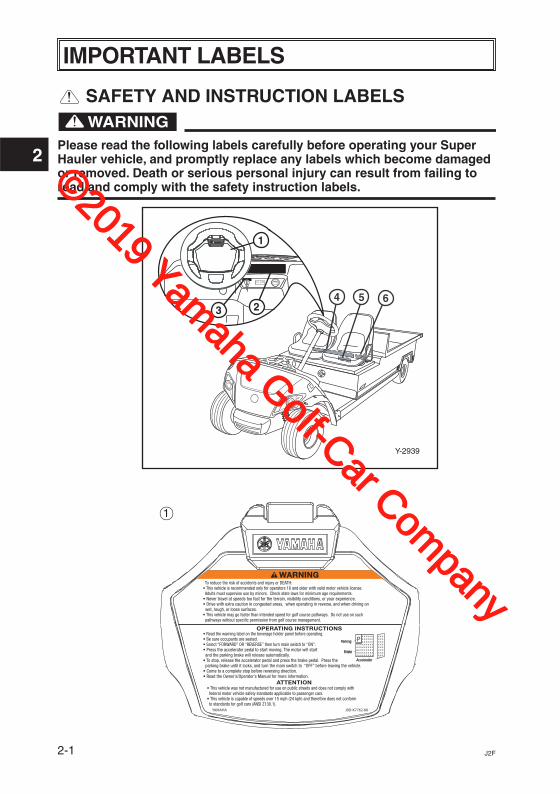
IMPORTANT LABELS
SAFETY AND INSTRUCTION LABELS
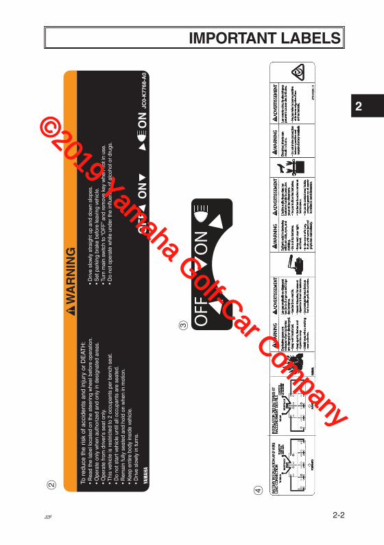
Please read the following labels carefully before operating your Super Hauler vehicle, and promptly replace any labels which become damaged or removed. Death or serious personal injury can result from failing to read and comply with the safety instruction labels.
WARNING To reduce the risk of accidents and injury or DEATH:• This vehicle is recommended only for operators 16 and older with valid motor vehicle license. Adults must supervise use by minors. Check state laws for minimum age requirements.• Never travel at speeds too fast for the terrain, visibility conditions, or your experience.• Drive with extra caution in congested areas, when operating in reverse, and when driving on wet, rough, or loose surfaces.• This vehicle may go faster than intended speed for golf course pathways. Do not use on such pathways without specific permission from golf course management.
• Read the warning label on the beverage holder panel before operating.• Be sure occupants are seated.• Select “FORWARD” OR “REVERSE” then turn main switch to “ON”.• Press the accelerator pedal to start moving. The motor will start and the parking brake will release automatically.• To stop, release the accelerator pedal and press the brake pedal. Press the parking brake until it locks, and turn the main switch to “OFF” before leaving the vehicle.• Come to a complete stop before reversing direction.• Read the Owner’s/Operator’s Manual for more information.
• This vehicle was not manufactured for use on public streets and does not comply with federal motor vehicle safety standards applicable to passenger cars.• This vehicle is capable of speeds over 15 mph (24 kph) and therefore does not conform to standards for golf cars (ANSI Z130.1).
OPERATING INSTRUCTIONS
ATTENTION
YAMAHA J0D-K7762-00
PParking
Brake
Accelerator
Y-2939
23
1
4 65
1
©2019 Yamaha Golf-Car Com
pany
2-2J2F
2
IMPORTANT LABELS
4
2
WA
RN
ING
JC0-
K77
68-A
0O
FF
ON
ON
To r
educ
e th
e ris
k of
acc
iden
ts a
nd in
jury
or
DE
ATH
:•
Rea
d th
e la
bel l
ocat
ed o
n th
e st
eerin
g w
heel
bef
ore
oper
atio
n.•
Ope
rate
onl
y w
hen
auth
oriz
ed a
nd o
nly
in d
esig
nate
d ar
eas.
• O
pera
te fr
om d
river
’s s
eat o
nly.
• Thi
s ve
hicl
e is
res
tric
ted
to 2
occ
upan
ts p
er b
ench
sea
t.•
Do
not s
tart
veh
icle
unt
il al
l occ
upan
ts a
re s
eate
d.•
Rem
ain
fully
sea
ted
and
hold
on
whe
n in
mot
ion.
• K
eep
entir
e bo
dy in
side
veh
icle
.•
Driv
e sl
owly
in tu
rns.
• D
rive
slow
ly s
trai
ght u
p an
d do
wn
slop
es.
• S
et p
arki
ng b
rake
bef
ore
leav
ing
vehi
cle.
• Tur
n m
ain
switc
h to
“OF
F” a
nd r
emov
e ke
y w
hen
not i
n us
e.•
Do
not o
pera
te w
hile
und
er th
e in
fluen
ce o
f alc
ohol
or
drug
s.
3
©2019 Yamaha Golf-Car Com
pany
2-3 J2F
2
IMPORTANT LABELS
5
6 YEAR
OF C
ONST
RUCT
ION:
****
MY*
***YA
MAHA
MOT
OR P
OWER
ED P
RODU
CTS
CO., L
TD20
0-1 S
AKAG
AWA,
KAK
EGAW
A, JA
PAN
MODE
L: **
**** *
**** *
*****
VEHI
CLE
WEI
GHT:
*****
kg (*
*** lb
)BA
TTER
Y W
EIGH
T: M
AX. *
** kg
NOMI
NAL S
YSTE
M VO
LTAG
E: **
V
MAX.
POW
ER: *
** hp
(***
kW)
LOAD
CAP
.: ***
kg (*
*** lb
)G.
V.W
.: ****
kg (*
*** lb
)
This
veh
icle
com
plie
s wi
th A
NSI/I
TSDF
B56
.8-2
011-
Part
III**
*-F
4236
-**
©2019 Yamaha Golf-Car Com
pany
2-4J2F
2
IMPORTANT LABELS
Y-2940
J2F-
0000
00
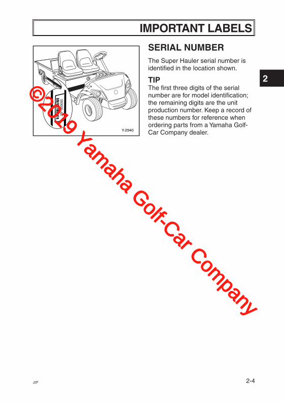
SERIAL NUMBERThe Super Hauler serial number is identified in the location shown.
TIPThe first three digits of the serial number are for model identification; the remaining digits are the unit production number. Keep a record of these numbers for reference when ordering parts from a Yamaha Golf- Car Company dealer.
©2019 Yamaha Golf-Car Com
pany
3-1 J2F
3
! OPERATOR SAFETY
Y-68
Y-2903
Yamaha Super Haulers are designed to be simple to operate. However, be sure to observe the following to reduce the risk of serious injury or death due to loss of control and other hazards::
BEFORE OPERATING THE SUPER HAULER• Read this Owner’s/Operator’s
manual and all safety and instruction labels on the Super Hauler before operating.
• Perform the pre-operation checks found in Section 6 of this manual.
• Only authorized people should drive the Super Hauler, from the driver’s side only, and only in designated areas.
• Do not allow more than two occupants per seat. This Super Hauler is restricted to two occupants, unless equipped with a rear seat.
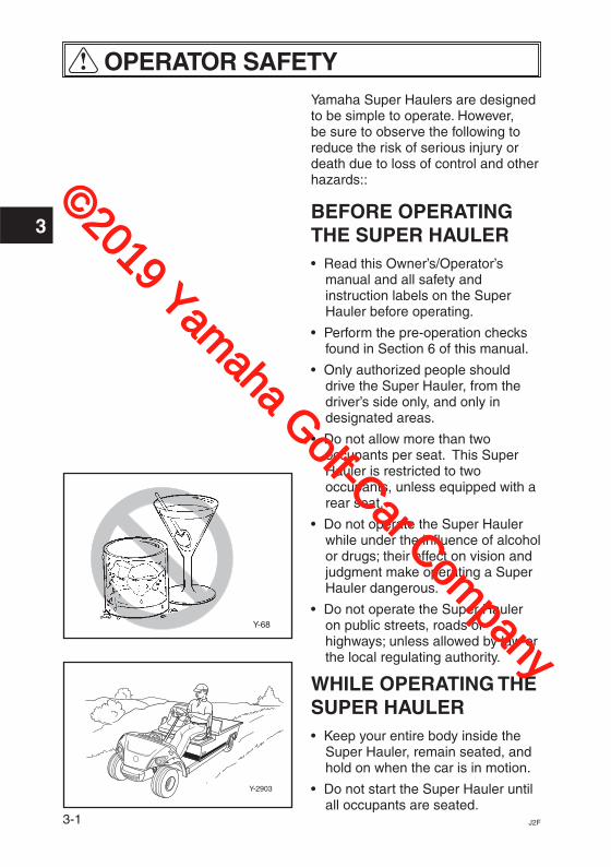
• Do not operate the Super Hauler while under the influence of alcohol or drugs; their effect on vision and judgment make operating a Super Hauler dangerous.
• Do not operate the Super Hauler on public streets, roads or highways; unless allowed by law or the local regulating authority.
WHILE OPERATING THE SUPER HAULER• Keep your entire body inside the
Super Hauler, remain seated, and hold on when the car is in motion.
• Do not start the Super Hauler until all occupants are seated.
©2019 Yamaha Golf-Car Com
pany
3-2J2F
3
! OPERATOR SAFETY
Y-2904
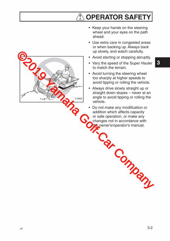
• Keep your hands on the steering wheel and your eyes on the path ahead.
• Use extra care in congested areas or when backing up. Always back up slowly, and watch carefully.
• Avoid starting or stopping abruptly.
• Vary the speed of the Super Hauler to match the terrain.
• Avoid turning the steering wheel too sharply at higher speeds to avoid tipping or rolling the vehicle.
• Always drive slowly straight up or straight down slopes – never at an angle to avoid tipping or rolling the vehicle.
• Do not make any modification or addition which affects capacity or safe operation, or make any changes not in accordance with the owner’s/operator’s manual.
©2019 Yamaha Golf-Car Com
pany
4-1 J2F
4
! SAFETY CONSIDERATIONSLike all machines, the Super Hauler can cause injury if improperly used or maintained.
Experience has shown that Super Haulers are safe when operated in accordance with the safety warnings affixed to every Super Hauler.
DRIVER QUALIFICATIONSAllow only authorized people to operate the Super Hauler. It is recommended that only people who possess a valid motor vehicle driver’s license be allowed to operate the Super Hauler.
Do not operate the Super Hauler when under the influence of alcohol or drugs. Death or serious personal injury can result from failing to comply with the safety and warning instructions affixed to the Super Hauler.
HAZARD PREVENTIONDrivers should be mindful of road hazards, and avoid dangerous situations that may include the following:
Steep Grades – Where steep grades exist, restrict the Super Hauler to designated roadway or path, and descend slowly with foot on the brake.
Descend steep grades slowly with foot on brake. Death or serious personal injury can result from failing to comply with the safety and warning instructions affixed to the Super Hauler.
Sharp Turns, Blind Corners and Bridge Approaches – Adhere to all warning signs and take proper precautions to avoid the hazard.
Wet Areas – Wet grass may cause a Super Hauler to lose traction and may affect stability. Vehicle operators should reduce speed in wet areas or during periods of inclement weather.
©2019 Yamaha Golf-Car Com
pany
4-2J2F
4
! SAFETY CONSIDERATIONSLoose Terrain – Avoid areas of loose terrain which may cause a Super Hauler to lose traction and affect stability. Take notice of conditions and reduce speed when driving on uneven or loose terrain.
Pedestrian Areas – Avoid areas with pedestrian traffic or congested areas whenever possible to prevent accidents. If it is impractical to avoid these areas, always remember that pedestrians have the right of way. When approaching pedestrian or congested areas always reduce speed, drive slowly, use caution and watch for pedestrians.
MAINTENANCE REQUIRED FOR SUPER HAULER SAFETYPractice the following to help ensure the safety of Super Hauler occupants:
• Preventative Maintenance. Perform all scheduled maintenance in accordance with manufacturer’s recommendations to provide a safe, properly operating Super Hauler.
• Personnel. Allow only qualified, trained and authorized personnel to inspect, adjust and maintain the Super Hauler.
• Parts and Materials. Use only replacement parts and materials recommended by the manufacturer.
• Ventilation. Properly ventilate all maintenance and storage areas in accordance with applicable fire codes and ordinances to avoid fire hazards. Ventilation is required to remove hydrogen gas from the Super Hauler storage areas during the battery charging process.
For electric powered vehicles, the amount of hydrogen gas emitted during charging depends on a number of factors, such as the condition of the batteries, the output rate of the battery charger and the amount of time the batteries are on charge. Because of the highly volatile nature of hydrogen gas and its propensity to rise and accumulate at the ceiling in pockets, a minimum of five air changes per hour is recommended. Consult applicable fire and safety codes for the specific ventilation levels requirement, as well as requirements for the use of explosion proof electrical apparatus.
©2019 Yamaha Golf-Car Com
pany

4-3 J2F
4
! SAFETY CONSIDERATIONS
SAFETY PRECAUTIONS DURING MAINTENANCEWhen performing maintenance, follow all safety instructions contained in the manufacturer’s operation and service manuals, as well as the following safety procedures:
• Properly immobilize Super Hauler before beginning any maintenance to avoid any unexpected vehicle movement.
• Properly block chassis before working underneath Super Hauler to avoid any unexpected vehicle movement.
• When working on the battery, do not smoke, or allow any sparks or open flames near the vehicle, to avoid any fires or explosions.
• Before working on an electric vehicle, disable the car’s electrical system in accordance with the manufacturer’s instructions to avoid electrical shock or damage to the electrical system.
• Use only properly insulated tools when working on electrically powered vehicles or around batteries to avoid electrical shock or damage to the electrical system.
• Maintain all safety devices including brakes, steering mechanisms, warning devices and governors, in a safe operating condition. Do not modify these safety devices as supplied by the manufacturer.
• After each maintenance or repair, the car must be driven by a qualified, trained and authorized person – in an area free of pedestrian traffic – to ensure proper operation and adjustment.
• Record all maintenance performed in a maintenance record log by date, name of person performing maintenance and type of maintenance. Periodically inspect maintenance log to ensure accurate and complete entries.
• Provide operator comment cards to assist in identifying non-periodic maintenance needs for specific Super Haulers.
• Maintain, in a legible condition, all nameplates, warnings and instructions provided by the manufacturer.
• If new nameplates, warnings or instructions are needed, contact your Yamaha dealer.
STORAGE AND BATTERY CHARGINGTake the following precautions to ensure maintenance worker safety:
• Only use battery changing and charging facilities and procedures that are in accordance with applic- able ordinances and regulations to avoid explosions, electrical shock or damage to the electrical system.
• Periodically inspect charging facili- ties and procedures to be certain that applicable safety codes, regulations and procedures are being followed to avoid any fires or explosions.
©2019 Yamaha Golf-Car Com
pany

5-1J2F
5
CONTROLS
P
BATTERY
ONOFF
Y-2941
213 4
5
6
7
8
9
5
1011
Y-2942
Y-2943
12
13
14
16 15
18
17
19
FEATURES1 Steering
wheel2 Main/Light
switch3 Drive select
switch4 Battery gauge5 USB ports6 Accelerator
pedal7 Brake pedal8 Parking brake
pedal9 Horn switcha Reflectorb Batteries
c Seatd Front bodye Headlightsf Front tireg Front bumperh DC charger
receptaclei Amber flasher
light j Tow switchk Rear tirel Rear cargo
aream Taillights
Y-2944
21
1022
20
©2019 Yamaha Golf-Car Com
pany
5-2 J2F
5
CONTROLS
Y-2838
BATTERY
ONOFF
Y-2839
ONOFF
BATTERY
Y-2840
BATTERY
ONOFF
Y-2841A
ONOFF
BATTERY
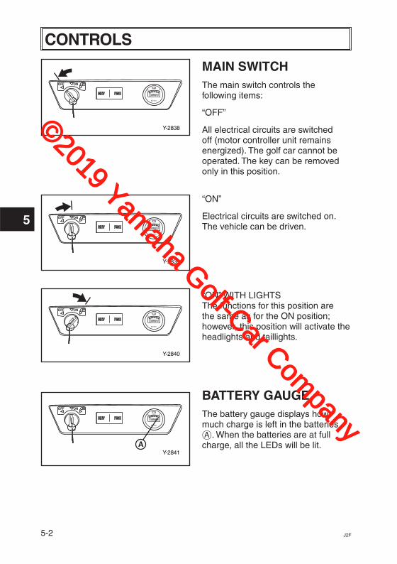
MAIN SWITCHThe main switch controls the following items:
“OFF”
All electrical circuits are switched off (motor controller unit remains energized). The golf car cannot be operated. The key can be removed only in this position.
“ON”
Electrical circuits are switched on. The vehicle can be driven.
“ON” WITH LIGHTS The functions for this position are the same as for the ON position; however, this position will activate the headlights and taillights.
BATTERY GAUGEThe battery gauge displays how much charge is left in the batteries å. When the batteries are at full charge, all the LEDs will be lit.
©2019 Yamaha Golf-Car Com
pany
5-3J2F
5
CONTROLS
Y-2842
ONOFF
BATTERY
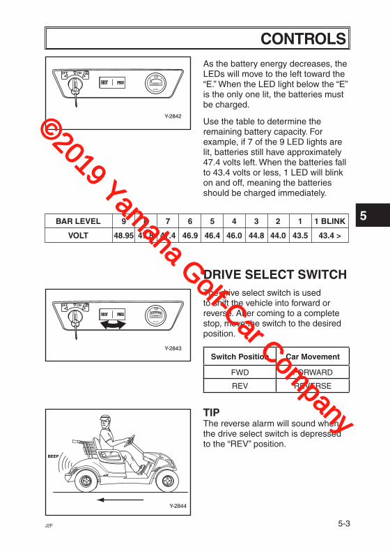
BAR LEVEL 9 8 7 6 5 4 3 2 1 1 BLINK
VOLT 48.95 47.8 47.4 46.9 46.4 46.0 44.8 44.0 43.5 43.4 >
Y-2843
ONOFF
BATTERY
Y-2844
BEEP
As the battery energy decreases, the LEDs will move to the left toward the “E.” When the LED light below the “E” is the only one lit, the batteries must be charged.
Use the table to determine the remaining battery capacity. For example, if 7 of the 9 LED lights are lit, batteries still have approximately 47.4 volts left. When the batteries fall to 43.4 volts or less, 1 LED will blink on and off, meaning the batteries should be charged immediately.
DRIVE SELECT SWITCHThe drive select switch is used to shift the vehicle into forward or reverse. After coming to a complete stop, move the switch to the desired position.
Switch Position Car Movement
FWD FORWARD
REV REVERSE
TIPThe reverse alarm will sound when the drive select switch is depressed to the “REV” position.
©2019 Yamaha Golf-Car Com
pany
5-4 J2F
5
CONTROLS
Y-20A
Y-21a
Y-22a
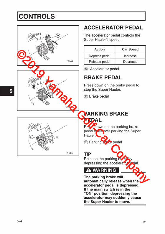
ACCELERATOR PEDALThe accelerator pedal controls the Super Hauler’s speed.
Action Car Speed
Depress pedal Increase
Release pedal Decrease
å Accelerator pedal
BRAKE PEDALPress down on the brake pedal to stop the Super Hauler.
∫ Brake pedal
PARKING BRAKE PEDALPress down on the parking brake pedal whenever parking the Super Hauler.
ç Parking brake pedal
TIPRelease the parking brake by depressing the accelerator pedal.
The parking brake will automatically release when the accelerator pedal is depressed. If the main switch is in the “ON” position, depressing the accelerator may suddenly cause the Super Hauler to move.
A
B
C
©2019 Yamaha Golf-Car Com
pany
5-5J2F
5
CONTROLS
Y-1995
TOW
RUN
A
Y-2840
BATTERY
ONOFF
Y-2932
1
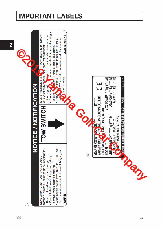
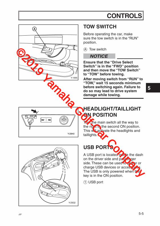
TOW SWITCHBefore operating the car, make sure the tow switch is in the “RUN” position.
å Tow switch
NOTICEEnsure that the “Drive Select Switch” is in the “FWD” position and then move the “TOW Switch” to “TOW” before towing.After moving switch from “RUN” to “TOW,” wait 15 seconds minimum before switching again. Failure to do so may lead to drive system damage while towing.
HEADLIGHT/TAILLIGHT ON POSITIONTurn the main switch all the way to the right to the second ON position. This will activate the headlights and taillights.
USB PORTSA USB port is located inside the dash on the driver side and passenger side. These can be used to power or charge USB devices or accessories. The USB is only powered when the key is in the ON position.
1 USB port
©2019 Yamaha Golf-Car Com
pany
5-6 J2F
5
CONTROLS
Y-901A
A
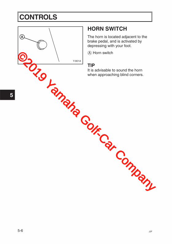
HORN SWITCHThe horn is located adjacent to the brake pedal, and is activated by depressing with your foot.
å Horn switch
TIPIt is advisable to sound the horn when approaching blind corners.
©2019 Yamaha Golf-Car Com
pany
6-1J2F
6
PRE-OPERATION CHECKS
Y-2725
Pre-operation checks should be made each time you use your Super Hauler. Get in the habit of performing the following checks in the same way so that they become second nature.
To keep vehicle from moving while performing pre-operation checks: • Remove main switch key. • Apply parking brake.
PRE-OPERATION CHECKSRefer to the Periodic Maintenance charts on pages 8-1 and 8-2.
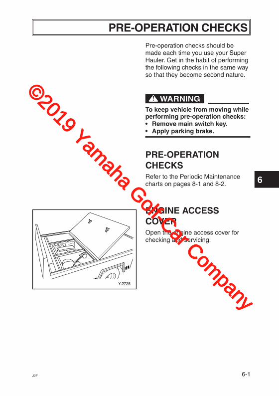
ENGINE ACCESS COVEROpen the engine access cover for checking and servicing.
©2019 Yamaha Golf-Car Com
pany
6-2 J2F
6
PRE-OPERATION CHECKS
Y-30
A
Y-31
BATTERY Charge batteries before each use. See charging steps in Chapter 8, Maintenance.
Check that the batteries are held securely in place to prevent the batteries from being damaged from vibration or jarring. Also check that no battery caps are missing to prevent battery acid from spilling from the battery. Check the battery terminals for corrosion.
Battery electrolyte is poisonous and dangerous, causing severe burns, etc. It contains sulfuric acid. Avoid contact with skin, eyes or clothing. Ventilate when charging or using in enclosed space. Always shield eyes when working near batteries. KEEP OUT OF REACH OF CHILDREN.
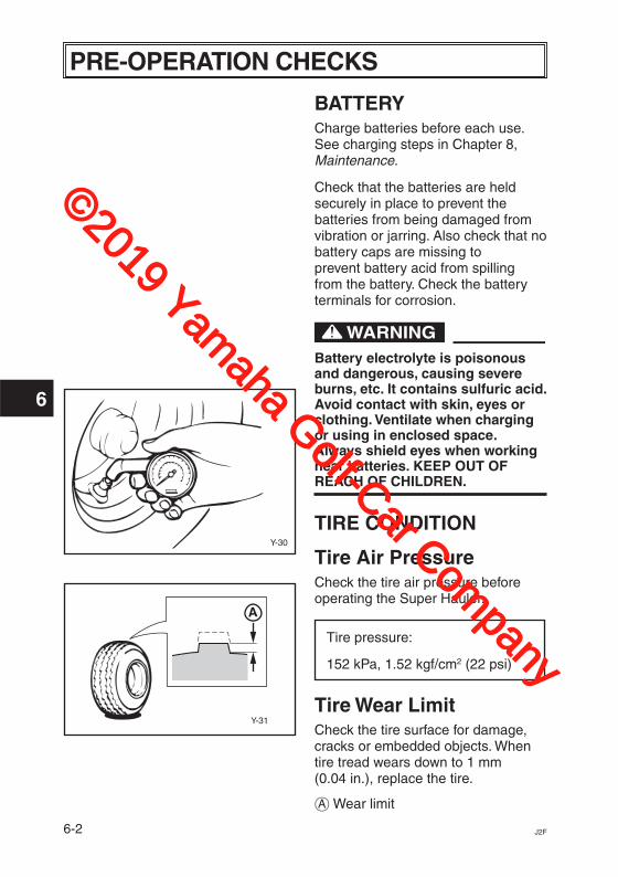
TIRE CONDITION
Tire Air PressureCheck the tire air pressure before operating the Super Hauler.
Tire pressure:
152 kPa, 1.52 kgf/cm2 (22 psi)
Tire Wear LimitCheck the tire surface for damage, cracks or embedded objects. When tire tread wears down to 1 mm (0.04 in.), replace the tire.
å Wear limit
©2019 Yamaha Golf-Car Com
pany
6-3J2F
6
PRE-OPERATION CHECKS
Y-2945
Y-2846
ONOFF
BATTERY
Y-20A
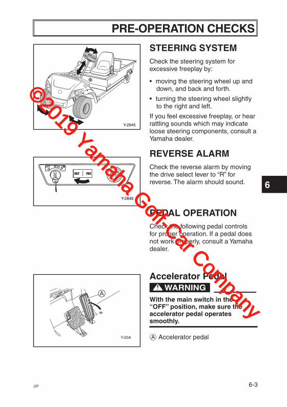
STEERING SYSTEMCheck the steering system for excessive freeplay by:
• moving the steering wheel up and down, and back and forth.
• turning the steering wheel slightly to the right and left.
If you feel excessive freeplay, or hear rattling sounds which may indicate loose steering components, consult a Yamaha dealer.
REVERSE ALARMCheck the reverse alarm by moving the drive select lever to “R” for reverse. The alarm should sound.
PEDAL OPERATIONCheck the following pedal controls for proper operation. If a pedal does not work properly, consult a Yamaha dealer.
Accelerator Pedal
With the main switch in the “OFF” position, make sure the accelerator pedal operates smoothly.
å Accelerator pedal
A
©2019 Yamaha Golf-Car Com
pany
6-4 J2F
6
PRE-OPERATION CHECKS
Y-21a
Y-22a
Y-2911
Y-901A
A
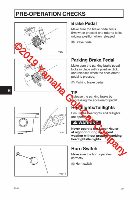
Brake PedalMake sure the brake pedal feels firm when pressed and returns to its original position when released.
∫ Brake pedal
Parking Brake PedalMake sure the parking brake pedal locks in place with a positive click, and releases when the accelerator pedal is pressed.
ç Parking brake pedal
TIPRelease the parking brake by depressing the accelerator pedal.
Headlights/TaillightsEnsure the headlights and taillights are operational.
Never operate the Super Hauler at night or during inclement weather without properly working headlights/taillights.
Horn SwitchMake sure the horn operates correctly.
å Horn switch
B
C
©2019 Yamaha Golf-Car Com
pany

7-1J2F
7
OPERATION
Y-2847
ONOFF
BATTERY
Y-2839
ONOFF
BATTERY
Y-20C
BODY AND CHASSISBefore each use, visually inspect the Super Hauler body and chassis for damaged and/or missing parts.
STARTING1. With the parking brake applied,
turn the drive select lever to “FWD” for forward, or “REV” for reverse.
NOTICEDo not shift from “FWD” (forward) to “REV” (reverse) while the Super Hauler is moving. Transmission damage can result.
2. Turn the main switch to “ON.”
Do not depress the accelerator pedal when turning on the main switch or the Super Hauler may suddenly start moving.
3. Check that your path is clear in the direction you plan to go, and slowly depress the accelerator pedal. The Super Hauler will start to move.
å Accelerator pedal
TIPThe parking brake automatically releases when the accelerator pedal is depressed.
A
©2019 Yamaha Golf-Car Com
pany
7-2 J2F
7
OPERATION
Y-65c
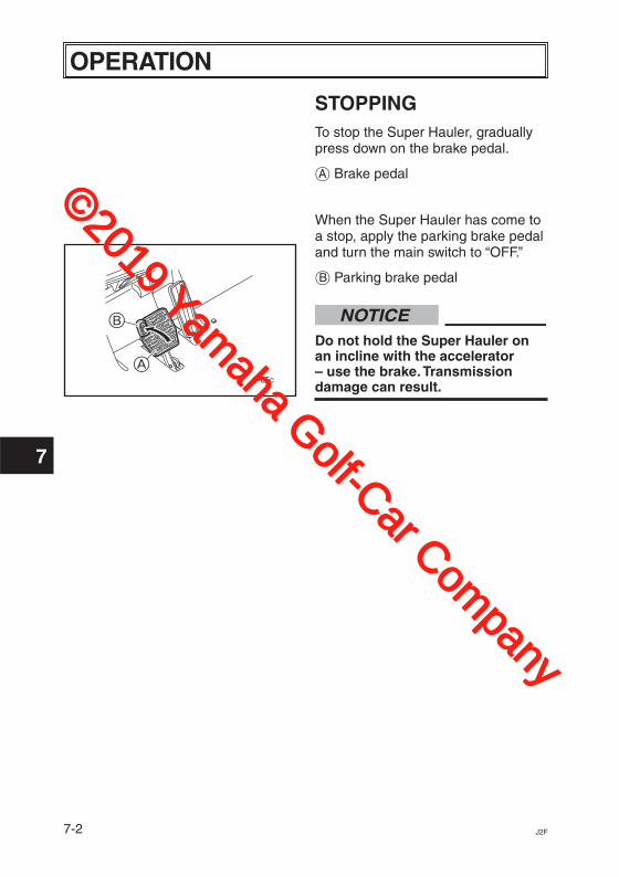
STOPPINGTo stop the Super Hauler, gradually press down on the brake pedal.
å Brake pedal
When the Super Hauler has come to a stop, apply the parking brake pedal and turn the main switch to “OFF.”
∫ Parking brake pedal
NOTICEDo not hold the Super Hauler on an incline with the accelerator – use the brake. Transmission damage can result.
A
B
©2019 Yamaha Golf-Car Com
pany
8-1J2F
8
MAINTENANCE
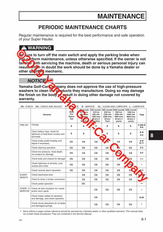
PERIODIC MAINTENANCE CHARTSRegular maintenance is required for the best performance and safe operation of your Super Hauler.
Be sure to turn off the main switch and apply the parking brake when you perform maintenance, unless otherwise specified. If the owner is not familiar with servicing the machine, death or serious personal injury can result. When in doubt the work should be done by a Yamaha dealer or other qualified mechanic.
NOTICEYamaha Golf-Car Company does not approve the use of high-pressure washers to clean the products they manufacture. Doing so may damage the finish on the body or result in doing other damage not covered by warranty.
DailyPre-
Opera-tion
20 hours100 miles160 kms(EveryMonth)
125 hrs600 mls
1000 kms(Every 6months)
250 hrs1200 mls2000 kms
(EveryYear)
500 hrs2500 mls4000 kms(Every 2years)
1000 hrs5000 mls8000 kms(Every 4years)
PageRemarks
40 rounds 250 rounds 500 rounds 1000 rounds 2000 rounds
ChargePRE-OP
EVERYMONTH
EVERY 6MONTHS
4-3/8-5/8-6
6-28-3/
6-4/8-11
*
*
*
*
—
6-3
6-3
6-2
7-1
8-3/8-4
* Items without a page number reference should be serviced by a Yamaha dealer or other qualified mechanic. This manual doesnot contain these procedures. They are contained in the Service Manual.
CS - CHECK CA - CHECK AND ADJUST R - REPLACE S - SERVICE CL - CLEAN AND LUBRICATE L - LUBRICATE
Clean battery tops, check fortightness of hold-down screws andterminals
Check brake pedal freeplay andadjust if necessary
Check steering operation
Check tire pressure, tread depth,tire surface for damage
Check body and chassis for damage
Check tightness of all bolts, nuts,screws and rivets
Check for loose or broken connections
Check all wire insulation for cracks
Check brake cables for abrasionand damage, and check operation
and/or worn spots
Check shock absorbers for oil leaksand damaged springs
Check pedal operation
Check reverse alarm operation
Check electrolyte level
S
S
CS
CS
CS
S
S
CA
CA
CS
CS
S
S
CA
CA
CS
S
S
CA
CA
CS
S
S
CA
CA
CS
S
S
CA
CA
CS
CS CS CS CS CS CS
CS CS CS CS CS CS
CS CS CS CS CS CS
CS CS CS CS CS
CS CS CS CS CS
CS CS CS CS
CS
CS CS CS CS
8-20
©2019 Yamaha Golf-Car Com
pany

8-2 J2F
8
MAINTENANCE
DailyPre-
Opera-tion
20 hours100 miles160 kms(EveryMonth)
125 hrs600 mls
1000 kms(Every 6months)
250 hrs1200 mls2000 kms
(EveryYear)
500 hrs2500 mls4000 kms(Every 2years)
1000 hrs5000 mls8000 kms(Every 4years)
PageRemarks
40 rounds 250 rounds 500 rounds 1000 rounds 2000 rounds
EVERYYEAR
EVERY 4YEARS
8-10/*
*
*
—
8-9
8-12
*
* Items without a page number reference should be serviced by a Yamaha dealer or other qualified mechanic. This manual doesnot contain these procedures. They are contained in the Service Manual.
CS - CHECK CA - CHECK AND ADJUST R - REPLACE S - SERVICE CL - CLEAN AND LUBRICATE L - LUBRICATE
Check wheel nut tightness, frontwheel bearing play
Check transaxle oil level andinspect for leakage
Perform a discharge test
Apply Terminal protectant
Inspect brake shoes and adjustor replace if necessary
Replace transaxle oil
S
S
S
S
S
S
CA
CS CS CS
CS CS CS
CS CS CS
*
*
Check rear axle bearing playfor roughness or freeplay
CA CA CA
R
EVERY 2YEARS *Replace brake cables R
Check steering knucklebushing freeplay / Adjustwheel alignment
Adjust parking brake release CA CA CA
©2019 Yamaha Golf-Car Com
pany
8-3J2F
8
MAINTENANCE
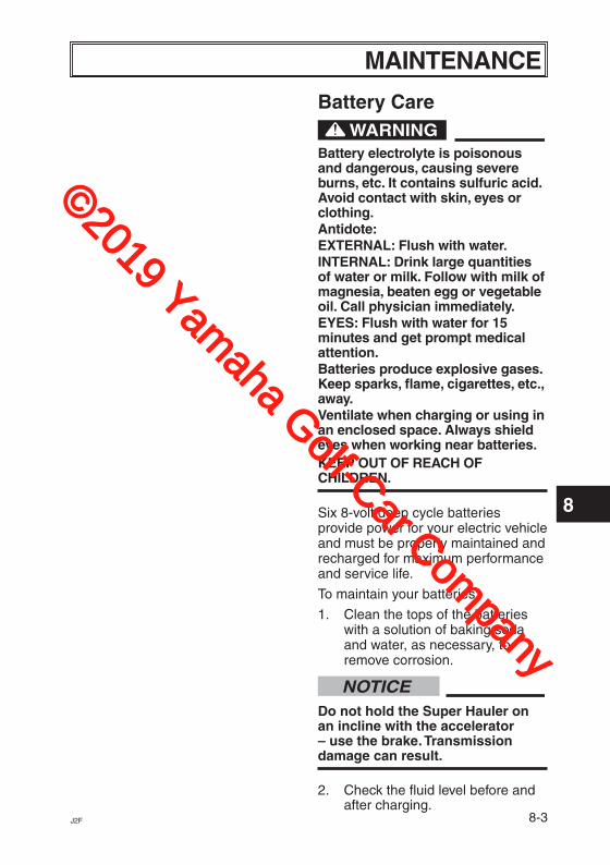
Battery Care
Battery electrolyte is poisonous and dangerous, causing severe burns, etc. It contains sulfuric acid. Avoid contact with skin, eyes or clothing.Antidote:EXTERNAL: Flush with water. INTERNAL: Drink large quantities of water or milk. Follow with milk of magnesia, beaten egg or vegetable oil. Call physician immediately.EYES: Flush with water for 15 minutes and get prompt medical attention.Batteries produce explosive gases. Keep sparks, flame, cigarettes, etc., away.Ventilate when charging or using in an enclosed space. Always shield eyes when working near batteries.KEEP OUT OF REACH OF CHILDREN.
Six 8-volt deep cycle batteries provide power for your electric vehicle and must be properly maintained and recharged for maximum performance and service life.
To maintain your batteries:
1. Clean the tops of the batteries with a solution of baking soda and water, as necessary, to remove corrosion.
NOTICEDo not hold the Super Hauler on an incline with the accelerator – use the brake. Transmission damage can result.
2. Check the fluid level before and after charging.
©2019 Yamaha Golf-Car Com
pany
8-4 J2F
8
MAINTENANCE
1/8"(3 mm)
Electrolyte 1/8" BelowBottom of Fill Well
Max. Level - discharged battery
Max. Level - charged battery
Fill Well
Electrolyte
Y-937c
Y-936a
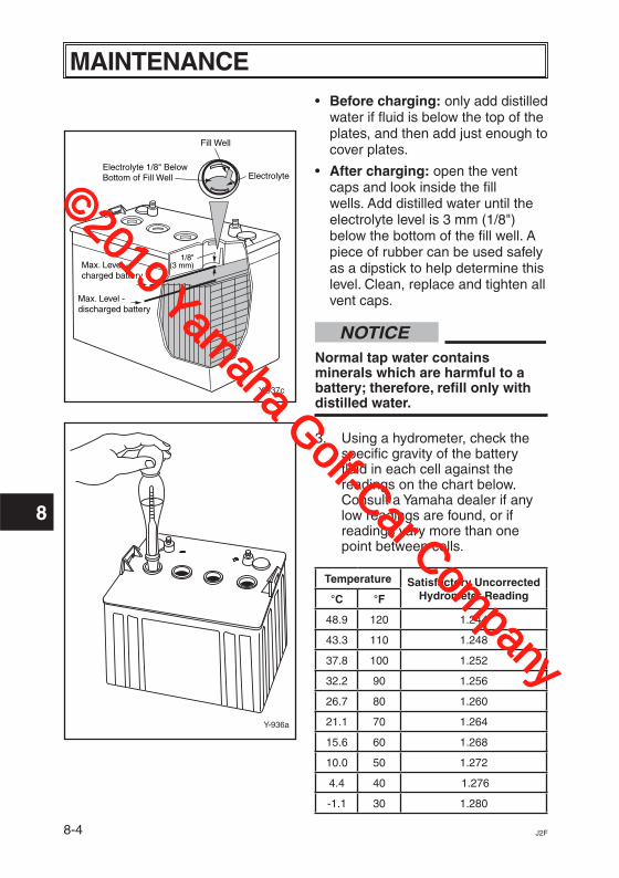
• Before charging: only add distilled water if fluid is below the top of the plates, and then add just enough to cover plates.
• After charging: open the vent caps and look inside the fill wells. Add distilled water until the electrolyte level is 3 mm (1/8") below the bottom of the fill well. A piece of rubber can be used safely as a dipstick to help determine this level. Clean, replace and tighten all vent caps.
NOTICENormal tap water contains minerals which are harmful to a battery; therefore, refill only with distilled water.
3. Using a hydrometer, check the specific gravity of the battery fluid in each cell against the readings on the chart below. Consult a Yamaha dealer if any low readings are found, or if readings vary more than one point between cells.
Temperature Satisfactory Uncorrected Hydrometer Reading°C °F
48.9 120 1.244
43.3 110 1.248
37.8 100 1.252
32.2 90 1.256
26.7 80 1.260
21.1 70 1.264
15.6 60 1.268
10.0 50 1.272
4.4 40 1.276
-1.1 30 1.280
©2019 Yamaha Golf-Car Com
pany
8-5J2F
8
MAINTENANCE
Y-2838
BATTERY
ONOFF
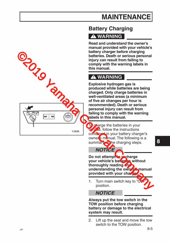
Battery Charging
Read and understand the owner’s manual provided with your vehicle’s battery charger before charging batteries. Death or serious personal injury can result from failing to comply with the warning labels in this manual.
Explosive hydrogen gas is produced while batteries are being charged. Only charge batteries in well-ventilated areas (a minimum of five air changes per hour is recommended). Death or serious personal injury can result from failing to comply with the warning labels in this manual.
To charge the batteries in your vehicle, follow the instructions contained in your battery charger’s owner’s manual. The following is a summary of the charging steps.
NOTICEDo not attempt to recharge your vehicle’s batteries without thoroughly reading and understanding the owner’s manual provided with your charger.
1. Turn main switch key to “OFF” position.
NOTICEAlways put the tow switch in the TOW position before charging battery or damage to the electrical system may result.
2. Lift up the seat and move the tow switch to the TOW position.
©2019 Yamaha Golf-Car Com
pany
8-6 J2F
8
MAINTENANCE
Y-669c
NOTICEUse only battery chargers that are rated for use with 48-volt Yamaha vehicles. Serious battery damage can result. Thoroughly read and understand the user manual supplied with your 48-volt charger.
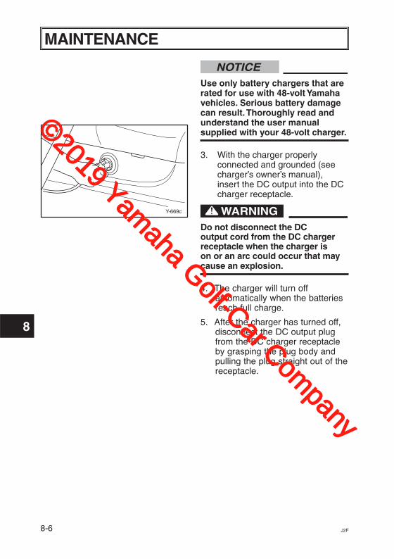
3. With the charger properly connected and grounded (see charger’s owner’s manual), insert the DC output into the DC charger receptacle.
Do not disconnect the DC output cord from the DC charger receptacle when the charger is on or an arc could occur that may cause an explosion.
4. The charger will turn offautomatically when the batteriesreach full charge.
5. After the charger has turned off,disconnect the DC output plugfrom the DC charger receptacleby grasping the plug body andpulling the plug straight out of thereceptacle.
©2019 Yamaha Golf-Car Com
pany
8-7J2F
8
MAINTENANCE
Y-751D
B CA
Y-672h
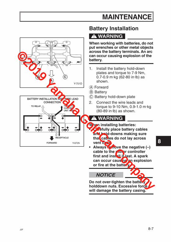
Battery Installation
When working with batteries, do not put wrenches or other metal objects across the battery terminals. An arc can occur causing explosion of the battery.
1. Install the battery hold-down plates and torque to 7-9 Nm, 0.7-0.9 m·kg (62-80 in·lb) as shown.
å Forward∫ Batteryç Battery hold-down plate
2. Connect the wire leads and torque to 9-10 Nm, 0.9-1.0 m·kg (80-89 in·lb) as shown.
When installing batteries:• Carefully place battery cables
and hold-downs making sure that cables do not lay across vent caps.
• Always remove the negative (–) cable to the motor controller first and install it last. A spark can occur causing an explosion or fire at the battery.
NOTICEDo not over-tighten the battery holddown nuts. Excessive force will damage the battery casing.
©2019 Yamaha Golf-Car Com
pany

8-8 J2F
8
MAINTENANCE
B
A
Y-2417
Fuse Type:10 Amp, Blade Style
Fuse Replacement
Be sure to use the specified fuse. Using a wrong fuse can cause electrical system damage and create a fire hazard.
NOTICEWhen replacing a fuse, be sure the main switch is turned off to prevent accidental short-circuiting and electrical system damage.
1. Locate the in-line fuse holder on the main wire harness adjacent to the tow switch.
2. Pull fuse holder cover off.
3. Pull fuse out, inspect and replace if necessary.
å Fuse holder∫ Fuse
©2019 Yamaha Golf-Car Com
pany
8-9J2F
8
MAINTENANCEMulti-Charge Steps: Ensures aconsistent and repeatable charge.
Step 1: Pre-test: Tests severalconditions before charging begins.If a problem is detected, charging isterminated.
Step 2: Constant Current Step:Battery is charged with full ratedoutput current, restoring up to 80%of charge.
Step 3: Constant Voltage Step:Regulated voltage “equalizes”individual battery cells, resulting infull charge delivered to the battery.
Step 4: Topping Off Step: Batterypack is brought slowly to full chargewithout excess gassing.
Step 5: Storage: Every 14th dayand if voltage becomes less than48V, charger restarts cycle torefresh batteries in storage.
Automatic Battery Equalization(Boosting): Automatically boostsbattery pack when individual cell-voltages are not balanced andrestores pack capacity.
BATTERY CHARGER
Prepare for EmergenciesBe prepared for possible injury or fire.Keep the following items handy:
� First aid kit � Fire extinguisher � Emergency phone numbers
Read the text located on the case ofthe charger before operating or usingthe charger.
Features Switch-Mode Design: High-efficiency operation with smooth,ripple-free DC output.
10-LED Display: Displays state ofcharge and charge error conditions.
Charge Protection: Protects fromimproper connection, overload andexcessive temperatures.Programmed safety features includecharge time monitoring and overtemperature protection.
Charge Algorithm: I-E-I - constantcurrent/constant voltage/constantcurrent charge profile.
Pre-Test: Performs severaldiagnostic tests before chargingbegins.
©2019 Yamaha Golf-Car Com
pany

8-10 J2F
8
MAINTENANCE
The output of chargers withgreater than 48 volts may pose anenergy and/or shock hazard undernormal use.
Installation The AC line connected to the chargermust be capable of supplying 12Amperes to the charger. AVOIDconnecting a charger and anotherdevice to a single 15A/20A circuit orthe circuit may become overloaded.Also, maximum Ampere variesdepending on AC voltage. Pleaserefer to “AC Input” in GeneralSpecifications.
RISK OF FIRE - Use this chargeronly on circuits with a 15-amp orhigher branch circuit protection(circuit breaker or fuse) inaccordance with the nationalelectrical code, ANSI/NFPA 70 andall applicable local codes andordinances.
When using an extension cord,use only a grounded, 3-wire, 12-AWG cord no longer than 15 m(50'). The use of an improperextension cord could result in arisk of a fire or electric shock.
©2019 Yamaha Golf-Car Com
pany

8-11J2F
8
MAINTENANCE
Mounting
This charger is not designed foron-board use. Improper mountingor installation could result in a riskof fire or damage to the golf car.
Mount the charger on a shelf or onthe wall with adequate ventilation.Ideally it will be mounted horizontallywith airflow from below. If it will bemounted vertically, it is recommendedthat the AC-input cord be at the lowerend of the charger.
Keep the charger free of oil, dirt, mudor dust to keep the cooling finsoperating as efficiently as possible.
Mount the charger by the mountingplate using appropriate fasteners.
TIPThe charger’s AC plug must be locat-ed at least 46 cm (18") above theground and the display visible to theuser.
Chargers can ignite flammablematerials and vapors. Do not usenear fuels, grain dust, solvents orother flammables.
Y-1675
©2019 Yamaha Golf-Car Com
pany
8-12 J2F
8
MAINTENANCE
Charging
To reduce the risk of an electricshock, connect only to a properlygrounded, single-phase (3-wire)outlet. Also, refer to groundinginstructions.
Risk of electric shock! Do nottouch any uninsulated parts of thecharger output plug, DC chargerreceptacle or battery terminals.
Surfaces may be hot. To avoid riskof burns, do not touch.
GroundingThe battery charger must begrounded to reduce the risk of electricshock. The charger is equipped witha 3-prong AC cord set. The AC cordset must be connected to anappropriate receptacle that is properlyinstalled and grounded in accordancewith the National Electrical Code andall local codes and ordinances.
Improper connection of theequipment-grounding conductorcan result in a risk of an electricshock.
The conductor with insulation thathas an outer surface that is green,with or without yellow stripe(s), is theequipment-grounding conductor. Ifrepair or replacement of the charger’sAC cord set is necessary, do notconnect the equipment-groundingconnector to a live terminal.
©2019 Yamaha Golf-Car Com
pany

8-13J2F
8
MAINTENANCE
Visually and manually inspect toverify that the DC output cord,plug and battery chargingreceptacle are in good workingcondition before each and everyuse. Do not use the charger underany of the following conditions: � The DC charging receptacle does
not grip the DC cord set plugtightly, is loose or does not makea good electrical connection.
� The DC cord set plug orcharging receptacle feels hotterthan normal.
� The DC cord set plug orcharging receptacle contacts arebent, corroded, or are dark orbluish in appearance.
� The DC cord set plug, cords,receptacle or equipment-charging wiring are cut, worn,broken or have any exposedconductors.
� The DC cord plug, cords, chargeror receptacles are damaged ordistressed in any way.
Using the charger with any of theabove symptoms could result in afire, property damage or personalinjury.
Do not disconnect the DC cord setplug from the DC chargerreceptacle when the charger is on.If the charger must be stopped,first disconnect the AC powersupply cord from its AC outlet, andthen disconnect the charger DCcord set plug from the DC chargerreceptacle.
Whenever removing AC or DC cordset plugs from receptacles, pullfrom the plug body and not fromtheir respective cords.
The instructions printed on thecharger (shown below) are for dailyreference. The charger is factorypreset for use with Trojan 48-volt golfcar batteries.
Charge only 48-volt batterysystems manufactured by TrojanBattery Company. Damage to thecharger and batteries may result ifthis charger is used on the wrongbattery type.
NOTICE
©2019 Yamaha Golf-Car Com
pany
8-14 J2F
8
MAINTENANCE
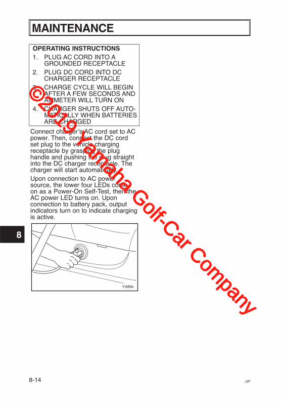
OPERATING INSTRUCTIONS1. PLUG AC CORD INTO A
GROUNDED RECEPTACLE2. PLUG DC CORD INTO DC
CHARGER RECEPTACLE3. CHARGE CYCLE WILL BEGIN
AFTER A FEW SECONDS ANDAMMETER WILL TURN ON
4. CHARGER SHUTS OFF AUTO-MATICALLY WHEN BATTERIESARE CHARGED
Connect charger’s AC cord set to ACpower. Then, connect the DC cord set plug to the vehicle chargingreceptacle by grasping the plughandle and pushing the plug straightinto the DC charger receptacle. Thecharger will start automatically. Upon connection to AC powersource, the lower four LEDs come on as a Power-On Self-Test, then theAC power LED turns on. Uponconnection to battery pack, outputindicators turn on to indicate chargingis active.
Y-669c
©2019 Yamaha Golf-Car Com
pany
8-15J2F
8
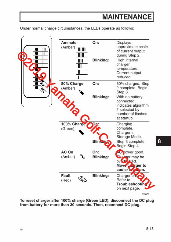
MAINTENANCEUnder normal charge circumstances, the LEDs operate as follows:
To reset charger after 100% charge (Green LED), disconnect the DC plugfrom battery for more than 30 seconds. Then, reconnect DC plug.
Ammeter(Amber)
On: Displaysapproximate scaleof current outputduring Step 2.
Blinking: High internalchargertemperature.Current outputreduced.
80% Charge(Amber)
On: 80% charged, Step 2 complete. BeginStep 3.
Blinking: With no batteryconnected,indicates algorithm# selected bynumber of flashesat startup.
100% Charge(Green)
On: Charging complete.Charger inStorage Mode.
Blinking: Step 3 complete.Begin Step 4.
AC On(Amber)
On: AC power good.
Fault(Red)
Blinking: Charger error.Refer toTroubleshootingon next page.
Blinking: Charger may beoverheated.Move charger tocooler location.
Y-1679
©2019 Yamaha Golf-Car Com
pany

8-16 J2F
8
MAINTENANCE
Troubleshooting1. LED Error Codes (For Battery Condition)
Incorrect reassembly may result in a risk of electric shock or fire. Thefollowing procedures are intended only to determine if a malfunction mayexist in the charger.
To reduce the risk of electric shock, always disconnect the charger’s AC cordset plug from AC power and its DC cord set plug from batteries beforeattempting any maintenance or cleaning.
Do not operate the charger if it is malfunctioning. Personal injury or propertydamage could result.
©2019 Yamaha Golf-Car Com
pany
8-17J2F
8
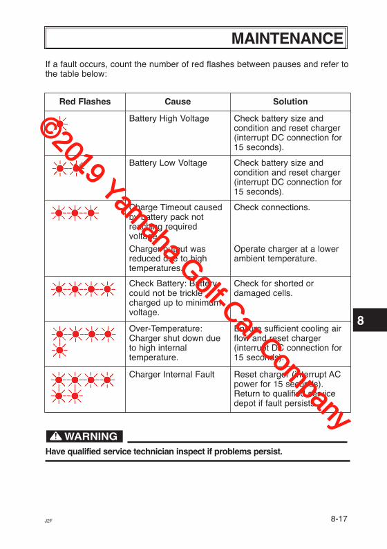
MAINTENANCEIf a fault occurs, count the number of red flashes between pauses and refer tothe table below:
Have qualified service technician inspect if problems persist.
Red Flashes Cause Solution
Battery High Voltage Check battery size andcondition and reset charger(interrupt DC connection for15 seconds).
Battery Low Voltage Check battery size andcondition and reset charger(interrupt DC connection for15 seconds).
Charge Timeout causedby battery pack notreaching requiredvoltage.
Charger output wasreduced due to hightemperatures.
Check connections.
Operate charger at a lowerambient temperature.
Check Battery: Batterycould not be tricklecharged up to minimumvoltage.
Check for shorted ordamaged cells.
Over-Temperature:Charger shut down dueto high internaltemperature.
Ensure sufficient cooling airflow and reset charger(interrupt DC connection for15 seconds).
Charger Internal Fault Reset charger (interrupt ACpower for 15 seconds).Return to qualified servicedepot if fault persists.
©2019 Yamaha Golf-Car Com
pany
8-18 J2F
8
MAINTENANCE
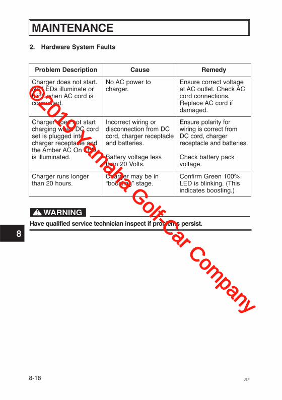
2. Hardware System Faults
Have qualified service technician inspect if problems persist.
Problem Description Cause Remedy
Charger does not start.No LEDs illuminate orblink when AC cord isconnected.
No AC power tocharger.
Ensure correct voltageat AC outlet. Check ACcord connections.Replace AC cord ifdamaged.
Charger does not startcharging when DC cordset is plugged intocharger receptacle andthe Amber AC On LEDis illuminated.
Incorrect wiring ordisconnection from DCcord, charger receptacleand batteries.
Battery voltage lessthan 20 Volts.
Ensure polarity forwiring is correct fromDC cord, chargerreceptacle and batteries.
Check battery packvoltage.
Charger runs longerthan 20 hours.
Charger may be in“boosting” stage.
Confirm Green 100%LED is blinking. (Thisindicates boosting.)
©2019 Yamaha Golf-Car Com
pany
J2F
8
MAINTENANCE
Y-2947
1
2
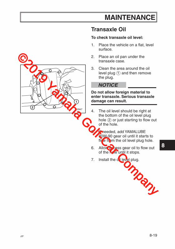
Transaxle OilTo check transaxle oil level:
1. Place the vehicle on a flat, level surface.
2. Place an oil pan under the transaxle case.
3. Clean the area around the oil level plug 1 and then remove the plug.
NOTICEDo not allow foreign material to enter transaxle. Serious transaxle damage can result.
4. The oil level should be right at the bottom of the oil level plug hole 2 or just starting to flow out of the hole.
5. If needed, add YAMALUBE 80W-90 gear oil until it starts to flow from the oil level plug hole.
6. Allow excess gear oil to flow out of the hole until it stops.
7. Install the oil level plug.
8-19
©2019 Yamaha Golf-Car Com
pany
8-20 J2F
8
MAINTENANCE
Y-57
Before performing wheel or brake maintenance, verify that the main switch is in the “OFF” position. Accidental starting of the vehicle could cause the vehicle to move, causing death or serious personal injury.
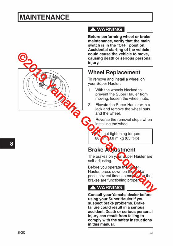
Wheel ReplacementTo remove and install a wheel on your Super Hauler:
1. With the wheels blocked to prevent the Super Hauler from moving, loosen the wheel nuts.
2. Elevate the Super Hauler with a jack and remove the wheel nuts and the wheel.
3. Reverse the removal steps when installing the wheel.
Wheel nut tightening torque:88 Nm, 8.8 m·kg (65 ft·lb)
Brake AdjustmentThe brakes on your Super Hauler are self-adjusting.
Before you operate the Super Hauler, press down on the brake pedal several times to make sure the brakes are functioning properly.
Consult your Yamaha dealer before using your Super Hauler if you suspect brake problems. Brake failure could result in a serious accident. Death or serious personal injury can result from failing to comply with the safety instructions in this manual.
©2019 Yamaha Golf-Car Com
pany
8-21J2F
8
MAINTENANCE
Y-62b
7
1817
1615
1413
1211
109
8
a
Y-61c
B A
Y-2281
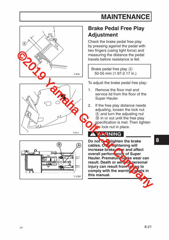
Brake Pedal Free Play AdjustmentCheck the brake pedal free play by pressing against the pedal with two fingers (using light force) and measuring the distance the pedal travels before resistance is felt.
Brake pedal free play Å: 50-55 mm (1.97-2.17 in.)
To adjust the brake pedal free play:
1. Remove the floor mat and service lid from the floor of the Super Hauler.
2. If the free play distance needs adjusting, loosen the lock nut å and turn the adjusting nut ∫ in or out until the free play specification is met. Then tighten the lock nut in place.
Do not over-tighten the brake cables. Over-tightening will increase brake wear and affect overall performance of Super Hauler. Premature brake wear can result. Death or serious personal injury can result from failing to comply with the warning labels in this manual.
©2019 Yamaha Golf-Car Com
pany

8-22 J2F
8
MAINTENANCE
Y-2823
1
2
34
5
Parking Brake Release Adjustment
NOTICEBefore performing parking brake release adjustment, adjust brake pedal free play.
1. Apply pressure to the parking brake pedal until the brake nail catches the first latch position on the sector.
2. Loosen the locknut and turn the bolt counterclockwise until it contacts the sector.
3. Turn the bolt clockwise 3/8 (120 degrees), then tighten locknut.
1 Parking brake pedal2 Bolt3 Locknut4 Brake nail5 Sector
©2019 Yamaha Golf-Car Com
pany
8-23J2F
8
MAINTENANCE
Y-2767
1
Y-2768
2
3
Y-2769
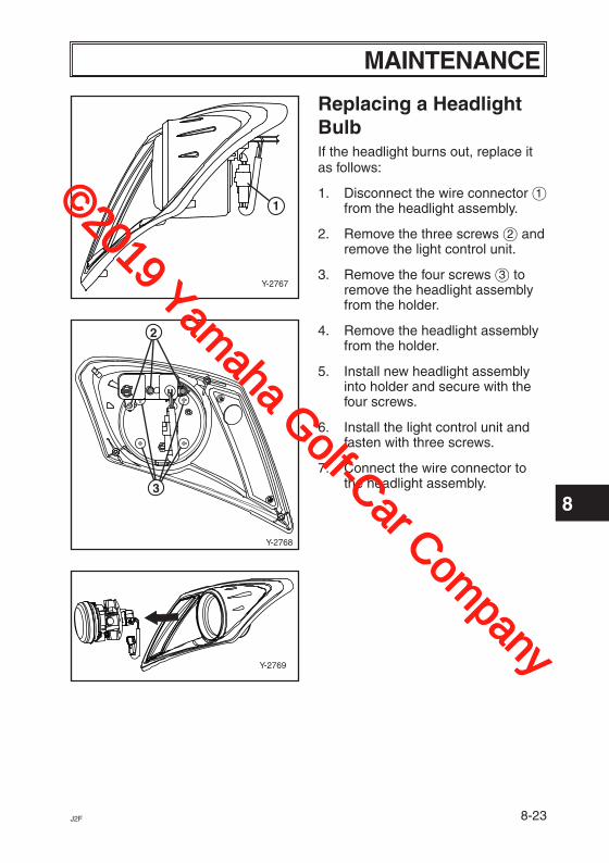
Replacing a Headlight BulbIf the headlight burns out, replace it as follows:
1. Disconnect the wire connector 1 from the headlight assembly.
2. Remove the three screws 2 and remove the light control unit.
3. Remove the four screws 3 to remove the headlight assembly from the holder.
4. Remove the headlight assembly from the holder.
5. Install new headlight assembly into holder and secure with the four screws.
6. Install the light control unit and fasten with three screws.
7. Connect the wire connector to the headlight assembly.
©2019 Yamaha Golf-Car Com
pany
8-24 J2F
8
MAINTENANCE
Y-2770
1
Y-2729
1
2
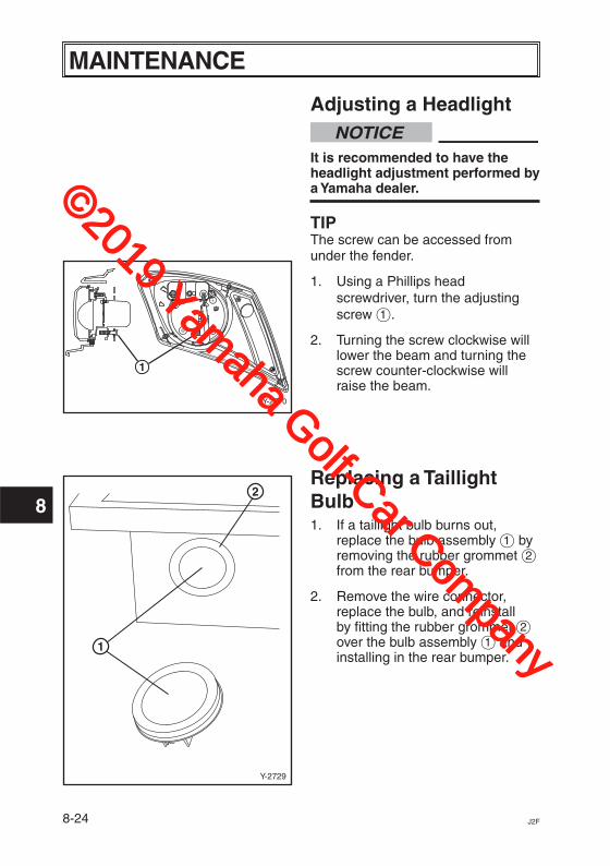
Adjusting a HeadlightNOTICE
It is recommended to have the headlight adjustment performed by a Yamaha dealer.
TIPThe screw can be accessed from under the fender.
1. Using a Phillips head screwdriver, turn the adjusting screw 1.
2. Turning the screw clockwise will lower the beam and turning the screw counter-clockwise will raise the beam.
Replacing a Taillight Bulb1. If a taillight bulb burns out,
replace the bulb assembly 1 by removing the rubber grommet 2 from the rear bumper.
2. Remove the wire connector, replace the bulb, and reinstall by fitting the rubber grommet 2 over the bulb assembly 1 and installing in the rear bumper.
©2019 Yamaha Golf-Car Com
pany
9-1J2F
9
STORAGEPerform the following preparations when storing your Super Hauler for extended periods of time.
NOTICEYamaha Golf-Car Company does not approve the use of high-pressure washers to clean the products they manufacture. Doing so may damage the finish on the body or result in doing other damage not covered by warranty.
TIPTurn main switch key to “OFF” position, remove key and store key in a safe place.
CHASSIS PREPARATION1. Verify the tire pressure is set to
152 kPa, 1.5 kgf/cm2 (max 22 psi).
2. Clean exterior of the Super Hauler and apply a rust inhibitor.
3. Cover the Super Hauler with a breathable cover and store it in a dry, well-ventilated area.
BATTERY PREPARATION1. Recharge the batteries and
check the fluid levels at least once a month.
NOTICEDo not allow cleaning solution to enter battery cells. Serious battery damage can result.
2. Clean the tops of the batteries with a solution of baking soda and water, as necessary, to remove corrosion.
©2019 Yamaha Golf-Car Com
pany
10-1 J2F
10
SPECIFICATIONS
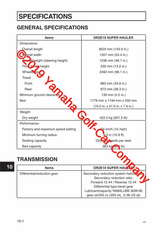
GENERAL SPECIFICATIONS
Items DR2E19 SUPER HAULER
Dimensions:
Overall length 3629 mm (142.9 in.)
Overall width 1357 mm (53.4 in.)
Overall height (steering height) 1236 mm (48.7 in.)
Floor board height 335 mm (13.2 in.)
Wheelbase 2492 mm (98.1 in.)
Tread:
Front 883 mm (34.8 in.)
Rear 973 mm (38.3 in.)
Minimum ground clearance 139 mm (5.5 in.)
Bed 1779 mm x 1194 mm x 200 mm
(70.0 in. x 47.0 in. x 7.9 in.)
Weight:
Dry weight 422.5 kg (931.5 lb)
Performance:
Factory and maximum speed setting 24 km/h (15 mph)
Minimum turning radius 3.3 m (10.8 ft)
Seating capacity One occupants per seat
Bed capacity 363 kg (800 lb)
TRANSMISSION
Items DR2E19 SUPER HAULER
Differential/reduction gear: Secondary reduction system helical gearSecondary reduction ratio:
Forward 12.44 / Reverse 12.44Differential type bevel gear
Lubricant/capacity YAMALUBE 80W-90 gear oil/355 cc (355 mL, 0.38 US qt)
©2019 Yamaha Golf-Car Com
pany
10-2J2F
10
SPECIFICATIONS
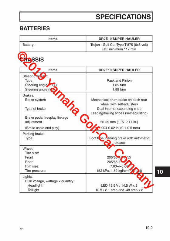
BATTERIES
Items DR2E19 SUPER HAULER
Battery: Trojan - Golf Car Type T-875 (6x8 volt)RC: minimum 117 min
CHASSIS
Items DR2E19 SUPER HAULER
Steering system:Type Steering angle (L.H.) Steering angle (R.H.)
Rack and Pinion
1.85 turn1.85 turn
Brakes:Brake system Type of brake Brake pedal freeplay linkage adjustment
(Brake cable end play)
Mechanical drum brake on each rear
wheel with self-adjusters Dual internal expanding shoe
Leading/trailing shoes (self-adjusting)
50-55 mm (1.97-2.17 in.)
0.004-0.02 in. (0.1-0.5 mm)
Parking brake:Type
Foot type; parking brake with automatic
release
Wheel:Tire size:FrontRearRim size:Tire pressure:
205/65-10 4PLY 205/65-10 4PLY
7.00–I–8.00 152 kPa, 1.52 kgf/cm2 (22 psi)
Lights:Bulb voltage, wattage x quantity:
HeadlightTaillight
LED 13.5 V / 14.5 W x 2 12 V / 2.1 amp and .48 amp x 2
©2019 Yamaha Golf-Car Com
pany

10-3 J2F
10
General Specifications
DC Output – see Operating Instructions
AC Input
Mechanical
Voltage - nom (V) 48
Voltage - max (V) 67.2
Current - max (A) 18
Battery Type Specific to selected algorithm
Reverse Polarity Electronic protection – auto-reset
Short Circuit Electronic current limit
Voltage - max (Vrms) 85-265
Frequency (Hz) 45-65
Current - max (Arms)12A @ 104VAC / 11.5A @ 110VAC /6.1A @ 200VAC / 5.6A @ 220VAC /5.4A @ 230VAC / 5.1A @ 240VAC
Current - nom (Arms) 10A @ 120VAC / 6A @ 200VAC /5A @ 230VAC
AC Power Factor >0.98 at nominal input current
Dimensions 28.0 x 24.5 x 14.0 cm(11 x 9.7 x 5.5")
Weight <5 kg (12 lbs)
Environmental Enclosure: IP46
Operating Temperature -30°C to +50°C ( -22°F to 122°F),derated above 30°C, below 0°C
Storage Temperature -40°C to +70°C (-40°F to 158°F)
AC Input Connector IEC320/C14 (require ≥ 1.8 m localized cord)
Safety Timeout 20.5 hours (24.5 hours when boosting)
SPECIFICATIONS BATTERY CHARGER
©2019 Yamaha Golf-Car Com
pany
10-4J2F
10
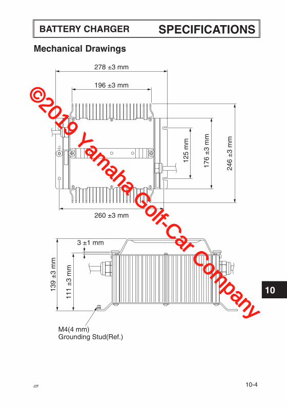
Mechanical Drawings
278 ±3 mm
196 ±3 mm
260 ±3 mm17
6 ±
3 m
m
125
mm
246
±3
mm
3 ±1 mm
M4(4 mm)Grounding Stud(Ref.)
139
±3
mm
111
±3
mm
SPECIFICATIONSBATTERY CHARGER
©2019 Yamaha Golf-Car Com
pany
11-1 J2F
11
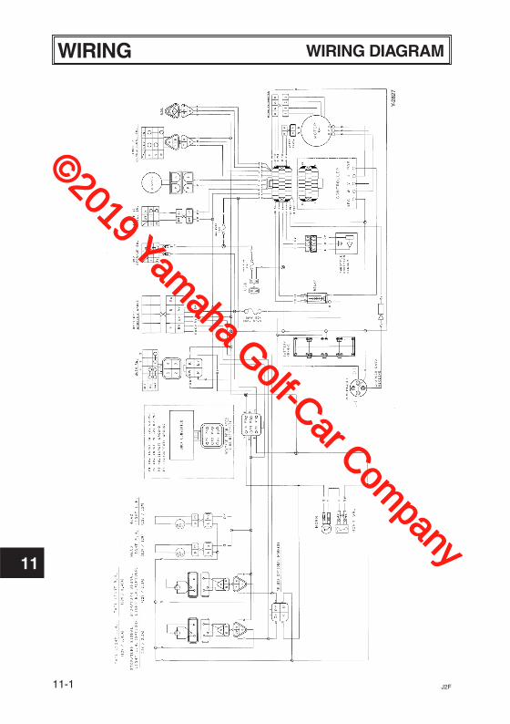
WIRING DIAGRAMWIRING
Y-28
27
©2019 Yamaha Golf-Car Com
pany

©2019 Yamaha Golf-Car Com
pany
PRINTED IN USA2018.12-0.3×2 CR
(E)
©2019 Yamaha Golf-Car Com
pany