Operate POR394-RW-RWDD-001 Raw Water Distribution Skid
Type
CONTINUOUS Document No.
TO-200-410 Rev/Mod
A-14 Release Date
10/25/2018 Page
1 of 34
Tank Farm Plant Operating Procedure WDS
USQ # TF-18-1700-S, Rev. 0
CHANGE HISTORY ( LAST 5 REV-MODS )
Rev-Mod Release Date Justification: Summary of Changes
A-14 10/25/2018 Update Procedure to Current
Field Conditions
Update information in Drain and Isolate POR394 for Heat Trace
Removal to refer to receiver vessel instead of "truck. Clarified
note to such. Added step to turn OFF circuit breakers on
POR394-RW-DP-001 and applicable table. Removal of V-033
Isolation valve from Pre-drain and Post-drain valve lineup.
A-13 04/26/2018 Update Procedure to Current
Field Conditions
Changes identified during PR process. Update Rad Con
Statement and Steps in Section 5.5 to provide direction to
disconnect drain hoses.
A-12 11/06/2017 Update Procedure to Current
Field Conditions
Added steps to allow for draining skid prior to disconnection of
heat trace elements. Updated Sign/Print(First & Last)/Date per
the standard. Added valve checklist to correlate draining of skid.
A-11 01/30/2017 Unincorporated Change
Added Note-Allow manual operation of MOV-001 and MOV-
002. Added Statement to Step- direction to operate manually as
directed by OE.
A-10 11/29/2016 Clarification of Transmitters Addition of Flow Indicating Transmitters Identifiers on
Instrument Calibration Checklist
Table of Contents Page
1.0 PURPOSE AND SCOPE ................................................................................................................ 3
1.1 Purpose ................................................................................................................................ 3
1.2 Scope ................................................................................................................................... 3
2.0 INFORMATION............................................................................................................................. 3
2.1 Terms and Definitions......................................................................................................... 3
2.2 General Information ............................................................................................................ 4
3.0 PRECAUTIONS AND LIMITATIONS......................................................................................... 5
3.1 Personnel Safety.................................................................................................................. 5
3.2 Equipment Safety ................................................................................................................ 5
3.3 Radiation and Contamination Control ................................................................................ 5
3.4 Environmental Compliance ................................................................................................ 6
4.0 PREREQUISITES .......................................................................................................................... 7
4.1 Performance Documents ..................................................................................................... 7
4.2 Field Preparation ................................................................................................................. 7
5.0 PROCEDURE ................................................................................................................................. 8
5.1 Pre-Start POR394-RW-RWDD-001 WDS ......................................................................... 8
Operate POR394-RW-RWDD-001 Raw Water Distribution Skid
Type
CONTINUOUS Document No.
TO-200-410 Rev/Mod
A-14 Release Date
10/25/2018 Page
2 of 34
5.2 Water Skid Start Up – Auto ................................................................................................ 9
5.3 Water Operations .............................................................................................................. 11
5.4 Shutdown POR394-RW-RWDD-001 WDS ..................................................................... 12
5.5 Drain and Isolate POR394-RW-RWDD-001 for Heat Trace Removal ............................ 13
5.6 Records ............................................................................................................................. 16
Checklist 1 - Initial Electrical Line-up ...................................................................................................... 17
Checklist 2 – POR 394 Initial Valve Line-up ........................................................................................... 18
Checklist 3 - Shutdown Valve Line-up ..................................................................................................... 20
Checklist 4 - Instrument Calibration Check .............................................................................................. 21
Checklist 5 - Instrument Operability Check ............................................................................................. 22
Checklist 6 – POR394 Upstream-Pre-Drain Valve Lineup ...................................................................... 24
Checklist 7 – POR394 Upstream- Post-Drain Valve Lineup ................................................................... 25
Checklist 8 - POR394 Downstream Pre-Drain Valve Lineup .................................................................. 26
Checklist 9 - POR394 Downstream- Post-Drain Valve Lineup ............................................................... 27
Figure 1 – Main Overview ........................................................................................................................ 28
Figure 2 – HMI Display Screen ................................................................................................................ 29
Figure 3 - Alarms ...................................................................................................................................... 30
Figure 4 – Analog Input Trend 1 .............................................................................................................. 31
Figure 5 - POR394-RW-RWDD-001 RWDD Diagram ........................................................................... 32
Operate POR394-RW-RWDD-001 Raw Water Distribution Skid
Type
CONTINUOUS Document No.
TO-200-410 Rev/Mod
A-14 Release Date
10/25/2018 Page
3 of 34
1.0 PURPOSE AND SCOPE
1.1 Purpose
This procedure provides instructions for operating POR394-RW-RWDD-001 Raw Water
Distribution Device (RWDD).
1.2 Scope
This procedure involves operating POR394-RW-RWDD-001 in local automatic mode.
2.0 INFORMATION
2.1 Terms and Definitions
HMI – Human Machine Interface
RWDD - Raw Water Distribution Device
WDS – Water Distribution Skid.
Operate POR394-RW-RWDD-001 Raw Water Distribution Skid
Type
CONTINUOUS Document No.
TO-200-410 Rev/Mod
A-14 Release Date
10/25/2018 Page
4 of 34
2.2 General Information
2.2.1 The boot-up process starts automatically when the RWDD system is
energized.
2.2.2 If water service is interrupted upstream of the backflow preventer
(supply line pressure to the assembly is lost or any upstream isolation valve is
shut), backflow preventer maintenance must take place prior to use of the
water skid. Water is supplied by MSA Water Services through supply line 4
“RW-100-M37” via isolation valves 331R and 83R.
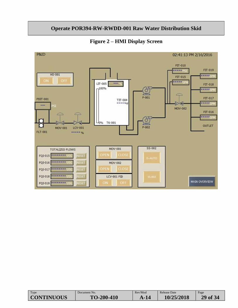
2.2.3 Figure 1 through Figure 4 display the various screens that are shown on the
HMI.
2.2.4 A signal from the PDIT to the PLC will result in an alarm at the HMI
indicating the strainer FLT-001 is experiencing a pressure differential of at
least 5 psid indicating attention is needed. The alarm will not shutdown
RWDD and will clear when the cause is relieved.
2.2.5 All labeling for RWDD is preceded by “POR394-RW-” throughout.
2.2.6 When positioning valves in this procedure, the following definitions/labels
apply:
OPEN: valve is positioned to OPEN, ON or O
CLOSED: valve is positioned to CLOSED, OFF, SHUT or S.
2.2.7 When positioning breakers in this procedure, the following definitions/labels
apply:
ON: Breaker is positioned to ON, CLOSED or I
OFF: Breaker is positioned to OFF, OPEN or O.
2.2.8 RPP-TE-58282 is the technical evaluation that documents that
POR394-RW-PRV-014 and POR394-RW-PRV-026 are code-compliant
pressure relief valves. The pressure relief valves have a set pressure of
150 psig (Defense In Depth (DID) control). This raw water system may be
used as supply water for Tank Farms waste transfer systems.
2.2.9 TFC-ENG-STD-023 Human-Machine Interface for Process Control Systems.
The HMI software does not comply with display of valves indicating travel,
however, the procedure does match the HMI readout.
Operate POR394-RW-RWDD-001 Raw Water Distribution Skid
Type
CONTINUOUS Document No.
TO-200-410 Rev/Mod
A-14 Release Date
10/25/2018 Page
5 of 34
3.0 PRECAUTIONS AND LIMITATIONS
3.1 Personnel Safety
3.1.1 If working around live circuits, extreme caution should be used. Failure to
follow electrical safety practices as outlined in DOE-0359 Hanford Site
Electrical Safety Program could result in serious injury.
3.2 Equipment Safety
CAUTION - If backflow preventer has been depressurized, backflow preventer must
be reset and certified.
NOTE - The following cautions apply to the whole procedure and do not appear in front
of any specific step in the body of this procedure.
3.2.1 Closing valves rapidly downstream of POR394 while pump is running may
result in water hammer.
3.2.2 Allowing the differential pressure across the strainer to exceed 20 psi could
cause damage to the strainer baskets.
3.2.3 Tamper seal on V-006 may be broken to close the valve in an upset backflow
preventer condition. In this event, backflow preventer maintenance and
reinstallation of the tamper seal must occur prior to restart of the skid.
3.2.4 Using the Emergency Stop button to shutdown the running pump could cause
damage to the pump and/or WDS equipment.
3.3 Radiation and Contamination Control
3.3.1 When this procedure is worked in radiological areas, an approved
radiological work permit (RWP) is required. If radiological conditions or
work performed falls outside the scope of the RWP, all work activities must
be discontinued until a new or revised RWP has been issued in accordance
with TFC-ESHQ-RP_RWP-C-03.
Operate POR394-RW-RWDD-001 Raw Water Distribution Skid
Type
CONTINUOUS Document No.
TO-200-410 Rev/Mod
A-14 Release Date
10/25/2018 Page
6 of 34
3.4 Environmental Compliance
3.4.1 In accordance with TFC-ESHQ-ENV_RM-C-04, Water Discharge in Tank
Farms, routine maintenance activities and operation activities may result in
small incidental discharge of raw water as long as the below listed limits and
conditions are met. Refer to TFC-ESHQ-ENV_RM-C-04, Table 2, for the
listing of approved incidental discharges.
No discharge from a single activity may exceed 60 gallons released to
the soil
Appropriate best management practices shall be implemented to
prevent unnecessary discharges
During performance of the work, all measures to limit ponding and/or
erosion will be implemented.
3.4.2 Immediately report any spill and/or releases to Shift Office. This includes
unplanned waste water discharges to surface contamination areas.
3.4.3 Discharge of raw water must be done in accordance with State Waste Water
Discharge Permit, ST-4511. Environmental approval is given to drain water
to drain field. Contact Environmental prior to discharge adjacent to the skid
for approval.

Operate POR394-RW-RWDD-001 Raw Water Distribution Skid
Type
CONTINUOUS Document No.
TO-200-410 Rev/Mod
A-14 Release Date
10/25/2018 Page
7 of 34
4.0 PREREQUISITES
4.1 Performance Documents
The following documents may be needed to perform this procedure:
TO-040-745, Perform Weatherization of Retrieval Buildings and Equipment
ARP-T-251-00033, Respond to Alarms at POR394-RW-RWDD-001 Raw Water
Distribution Skid
TFC-ESHQ-ENV_RM-C-04, Water Discharge in Tank Farms.
4.2 Field Preparation
4.2.1 CHECK the following initial outlet valve for use:
[ ] V-031 – Outlet 5 Isolation Valve (Spare)
[ ] V-032 – Outlet 4 Isolation Valve (Spare)
[ ] V-033 – Outlet 3 Isolation Valve (POR395)
[ ] V-034 – Outlet 2 Isolation Valve (POR385)
[ ] V-035 – Outlet 1 Isolation Valve (Spare).

Operate POR394-RW-RWDD-001 Raw Water Distribution Skid
Type
CONTINUOUS Document No.
TO-200-410 Rev/Mod
A-14 Release Date
10/25/2018 Page
8 of 34
5.0 PROCEDURE
NOTE - Section 5.5 can be performed independently of Sections 5.1 through 5.4.
5.1 Pre-Start POR394-RW-RWDD-001 WDS
NOTE - Steps 5.1.1 through 5.1.7 may be performed in any logical order.
5.1.1 CONFIRM Section 4.2 has been completed.
5.1.2 IF at least one of the following is true, COMPLETE electrical component
line-up per Checklist 1:
Directed by OE
POR394 water skid has been shut down for more than 30 days.
CAUTION
If backflow preventer has been depressurized, backflow preventer must
be reset and certified.
5.1.3 IF at least one of the following is true, COMPLETE valve line-up per
Checklist 2:
Directed by OE
POR394 water skid has been shut down for more than 30 days.
NOTE - Checklist 4 may be performed by attaching and reviewing a previous copy of
Checklist 4 (completed within four weeks).
5.1.4 ENSURE instrument calibration check is performed per Checklist 4.
5.1.5 IF shutdown 24 hours, COMPLETE instrument operability check per
Checklist 5.
5.1.6 COMPARE Checklist 4 and Checklist 5 with AY Farm RATL.
5.1.6.1 IF any discrepancy is discovered, UPDATE checklists.
5.1.7 ENSURE cold or warm weather preparations are performed per TO-040-745.
Operate POR394-RW-RWDD-001 Raw Water Distribution Skid
Type
CONTINUOUS Document No.
TO-200-410 Rev/Mod
A-14 Release Date
10/25/2018 Page
9 of 34
5.2 Water Skid Start Up – Auto
5.2.1 CONFIRM Section 5.1 has been completed.
5.2.2 IF PIT-010 is above 50 psig, PERFORM the following:
5.2.2.1 OPEN valve V-022.
5.2.2.2 WHEN PIT-010 is below 35 psig, CLOSE valve V-022.
NOTE - At initial start-up, some alarms may appear that are incorrect due to the timing
of how components actually get powered up and establish communication. At
initial power-up it may be necessary to access the alarm screen, and
acknowledge, reset alarms. After initial power-up respond to any subsequent
alarms per ARP-T-251-00033.
5.2.3 IF initial start-up or when directed by OE, COMPLETE the following:
5.2.3.1 PRESS ALARM to access the ALARM HISTORY.
5.2.3.2 PRESS ACKNOWLEDGE ALL.
5.2.3.3 PRESS CLEAR ALARM HISTORY.
5.2.3.4 PRESS MAIN OVERVIEW to exit Alarm History.
NOTE - The system only requires one water pump to be enabled in order to start
operation. Selector Switch SS-002: “0” = AUTO, “1” = P-001, “2” = P-002.
When both pumps are enabled by selecting “0” at SS-002, the pump selection
is in AUTO and will alternate between P-001 and P-002 on successive
start/stop cycles.
- MOV-001 and MOV-002 may be operated manually as directed by OE.
5.2.4 GO TO the P&ID screen on HMI AND
ENSURE MOV-001 and MOV-002 are OPEN,
OR
OPERATE manually as directed by OE.

Operate POR394-RW-RWDD-001 Raw Water Distribution Skid
Type
CONTINUOUS Document No.
TO-200-410 Rev/Mod
A-14 Release Date
10/25/2018 Page
10 of 34
5.2 Water Skid Start Up – Auto (Cont.)
5.2.5 ENSURE POR394 SS-002 indicates AUTO pump selection mode
(SS-002 indicates “0” is selected).
5.2.6 START pump by selecting “ON” at HS-001 on the HMI.
NOTE - To enhance the flush flow rate of the Raw Water system, the non-operating
pump should be isolated.
5.2.7 IF Pump P-001 is running, CLOSE valve V-024,
OR
5.2.8 IF Pump P-002 is running, CLOSE valve V-023.

Operate POR394-RW-RWDD-001 Raw Water Distribution Skid
Type
CONTINUOUS Document No.
TO-200-410 Rev/Mod
A-14 Release Date
10/25/2018 Page
11 of 34
5.3 Water Operations
NOTE - Quickly closing water discharge valves may result in discharge from PRV.
5.3.1 WHEN directed, OPEN, THROTTLE, OR SLOWLY CLOSE the
following valves:
V-031 (Outlet 5 Isolation Valve)
V-032 (Outlet 4 Isolation Valve)
V-033 Outlet 3 Isolation Valve (POR395)
V-034 Outlet 2 Isolation Valve (POR385)
V-035 (Outlet 1 Isolation Valve).
5.3.2 WHEN directed, GO TO the P&ID screen on HMI AND
PRESS OFF from HS-001.

Operate POR394-RW-RWDD-001 Raw Water Distribution Skid
Type
CONTINUOUS Document No.
TO-200-410 Rev/Mod
A-14 Release Date
10/25/2018 Page
12 of 34
5.4 Shutdown POR394-RW-RWDD-001 WDS
5.4.1 COMPLETE shutdown valve line-up per Checklist 3.
Operate POR394-RW-RWDD-001 Raw Water Distribution Skid
Type
CONTINUOUS Document No.
TO-200-410 Rev/Mod
A-14 Release Date
10/25/2018 Page
13 of 34
5.5 Drain and Isolate POR394-RW-RWDD-001 for Heat Trace Removal
Special Instruction:
Valves may need to be repeatedly Open and/or Closed at the direction of the OE during
the draining of the tank activities to allow appropriate water drainage.
5.5.1 ENSURE MSA has isolated water from 4” RW100 M37.
5.5.2 ENSURE all MOV’s with Auto/Manual selection are placed in “MANUAL”
mode.
5.5.3 ENSURE the following breakers on POR394-RW-DP-001 are ON prior to
draining:
Main Breaker
Breaker 2/4.
Drain POR394 Skid Upstream of Tank
5.5.4 ENSURE valves and components are in the position identified for Upstream
Pre-Drain in Checklist 6.
5.5.5 OPEN valve POR394-RW-V-011 AND VERIFY level in supply tank is not
increasing.
5.5.6 ENSURE drain hoses are connected and routed to drain field or appropriate
container.
5.5.7 OPEN valve POR394-RW-V-009 and POR394-RW-V-010 AND ALLOW
water to drain.
5.5.8 DRAIN system until 1 drop per second flows through drain valves.
5.5.9 ENSURE valves and components are left in the position identified for
Upstream Post-Drain in Checklist 7.

Operate POR394-RW-RWDD-001 Raw Water Distribution Skid
Type
CONTINUOUS Document No.
TO-200-410 Rev/Mod
A-14 Release Date
10/25/2018 Page
14 of 34
5.5 - Drain and Isolate POR394-RW-RWDD-001 for Heat Trace Removal
(Cont.)
Drain Tank near POR394
5.5.10 ENSURE Circuit #15 on Panel 394-RW-DP-001 is in OFF position.
5.5.11 ENSURE POR394-RW-HTR-001 is not energized.
NOTE - A receiver vessel for draining the system is required.
5.5.12 POSITION water receiver vessel near POR394-RW-RWDD-001.
5.5.13 CONNECT 1” hose to POR394-RW-V-019 drain valve.
5.5.14 POSITION opposite end of hose inside holding tank.
5.5.15 OPEN POR394-RW-V-019 drain valve.
5.5.16 ALLOW water to drain into holding tank until 1 drop per second flows
from hose.
5.5.17 DISCONNECT 1” hose from POR394-RW-V-019 drain valve.
Operate POR394-RW-RWDD-001 Raw Water Distribution Skid
Type
CONTINUOUS Document No.
TO-200-410 Rev/Mod
A-14 Release Date
10/25/2018 Page
15 of 34
5.5 - Drain and Isolate POR394-RW-RWDD-001 for Heat Trace Removal
(Cont.)
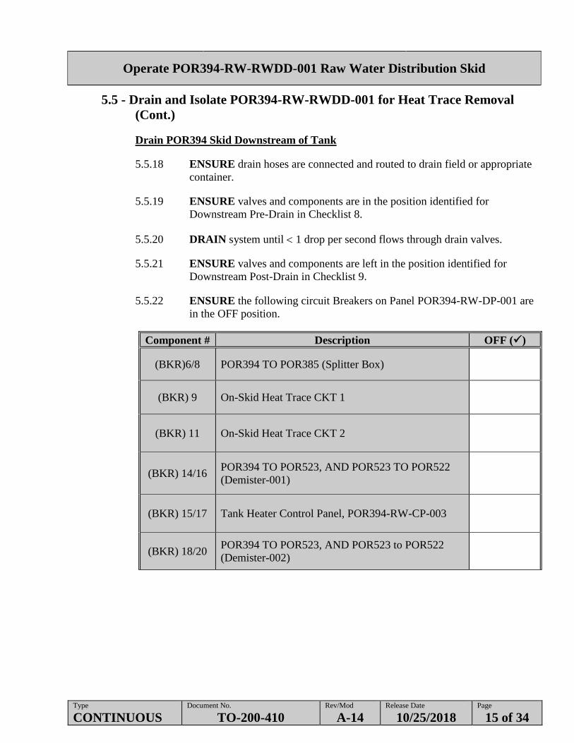
Drain POR394 Skid Downstream of Tank
5.5.18 ENSURE drain hoses are connected and routed to drain field or appropriate
container.
5.5.19 ENSURE valves and components are in the position identified for
Downstream Pre-Drain in Checklist 8.
5.5.20 DRAIN system until 1 drop per second flows through drain valves.
5.5.21 ENSURE valves and components are left in the position identified for
Downstream Post-Drain in Checklist 9.
5.5.22 ENSURE the following circuit Breakers on Panel POR394-RW-DP-001 are
in the OFF position.
Component # Description OFF ()
(BKR)6/8 POR394 TO POR385 (Splitter Box)
(BKR) 9 On-Skid Heat Trace CKT 1
(BKR) 11 On-Skid Heat Trace CKT 2
(BKR) 14/16 POR394 TO POR523, AND POR523 TO POR522
(Demister-001)
(BKR) 15/17 Tank Heater Control Panel, POR394-RW-CP-003
(BKR) 18/20 POR394 TO POR523, AND POR523 to POR522
(Demister-002)
Operate POR394-RW-RWDD-001 Raw Water Distribution Skid
Type
CONTINUOUS Document No.
TO-200-410 Rev/Mod
A-14 Release Date
10/25/2018 Page
16 of 34
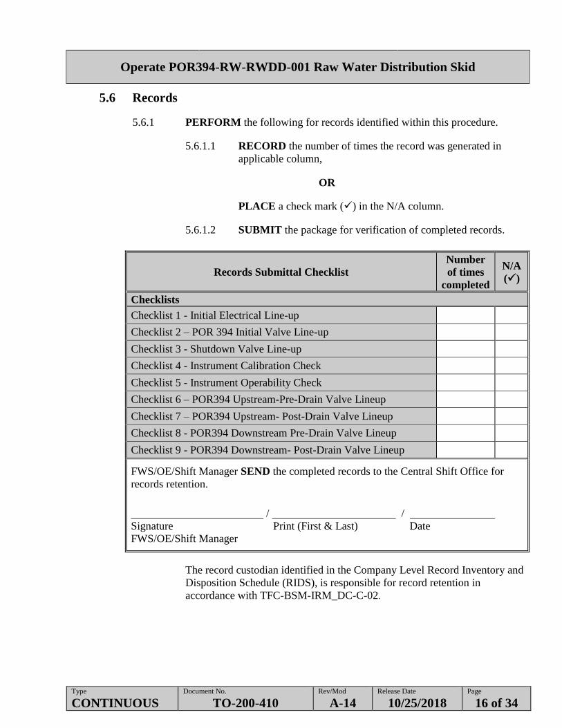
5.6 Records
5.6.1 PERFORM the following for records identified within this procedure.
5.6.1.1 RECORD the number of times the record was generated in
applicable column,
OR
PLACE a check mark () in the N/A column.
5.6.1.2 SUBMIT the package for verification of completed records.
Records Submittal Checklist
Number
of times
completed
N/A
()
Checklists
Checklist 1 - Initial Electrical Line-up
Checklist 2 – POR 394 Initial Valve Line-up
Checklist 3 - Shutdown Valve Line-up
Checklist 4 - Instrument Calibration Check
Checklist 5 - Instrument Operability Check
Checklist 6 – POR394 Upstream-Pre-Drain Valve Lineup
Checklist 7 – POR394 Upstream- Post-Drain Valve Lineup
Checklist 8 - POR394 Downstream Pre-Drain Valve Lineup
Checklist 9 - POR394 Downstream- Post-Drain Valve Lineup
FWS/OE/Shift Manager SEND the completed records to the Central Shift Office for
records retention.
/ /
Signature Print (First & Last) Date
FWS/OE/Shift Manager
The record custodian identified in the Company Level Record Inventory and
Disposition Schedule (RIDS), is responsible for record retention in
accordance with TFC-BSM-IRM_DC-C-02.

Operate POR394-RW-RWDD-001 Raw Water Distribution Skid
Type
CONTINUOUS Document No.
TO-200-410 Rev/Mod
A-14 Release Date
10/25/2018 Page
17 of 34
Checklist 1 - Initial Electrical Line-up
Date:
Component # Description Position Check ()
POR394-RW-RWDD-001
POR394-RW-DS-001 Skid 480VAC Supply Main Disconnect ON
POR394-RW-DS-002 Safety Disconnect Switch ON
POR394-RW-DS-003 Safety Disconnect Switch ON
POR394-RW-CP-001 (PLC Control Panel)
POR394-RW-DS-005 Power ON
POR394-RW-PB-001* Estop PULLED OUT
POR394-RW-CP-002 (Pump VFD Control Panel)
POR394-RW-DS-004 Power ON
POR394-RW-DP-001
MAIN Main ON
(BKR) 1 GFCI Duplex Receptacle ON
(BKR) 2/4 POR394 RW Supply ON
(BKR) 3 GFCI Duplex Receptacle ON
(BKR) 5 Lighting ON
(BKR)6/8 POR394 TO POR385 (Splitter Box) ON
(BKR) 7 Lighting ON
(BKR) 9 On-Skid Heat Trace CKT 1 ON
(BKR) 10/12 POR394 TO POR395 (Water Filter Skid) ON
(BKR) 11 On-Skid Heat Trace CKT 2 ON
(BKR) 13 Control Panel, POR394-RW-CP-001 ON
(BKR) 14/16 POR394 TO POR523, AND POR523 TO POR522
(Demister-001)
ON
(BKR) 15/17 Tank Heater Control Panel, POR394-RW-CP-003 ON
(BKR) 18/20 POR394 TO POR523, AND POR523 to POR522
(Demister-002)
ON
(BKR) 22/24 Tank Level Gauge Heat Trace CKT ON
* WHEN ESTOP has activated and then pulled out POR394-RW-MOV-002 will OPEN.
/ /
Signature Print (First & Last) Date
Operator
NOTE - When positioning breakers in this procedure, the following definitions/labels apply:
- ON: Breaker is positioned to ON, CLOSED or I.
- OFF: Breaker is positioned to OFF, OPEN or O.
- IF no power at POR394, CHECK Breaker ON.
/ /
Signature Print (First & Last) Date
Shift Manager /OE
Operate POR394-RW-RWDD-001 Raw Water Distribution Skid
Type
CONTINUOUS Document No.
TO-200-410 Rev/Mod
A-14 Release Date
10/25/2018 Page
18 of 34
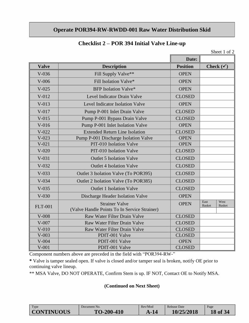
Checklist 2 – POR 394 Initial Valve Line-up
Sheet 1 of 2
Date:
Valve Description Position Check ()
V-036 Fill Supply Valve** OPEN
V-006 Fill Isolation Valve* OPEN
V-025 BFP Isolation Valve* OPEN
V-012 Level Indicator Drain Valve CLOSED
V-013 Level Indicator Isolation Valve OPEN
V-017 Pump P-001 Inlet Drain Valve CLOSED
V-015 Pump P-001 Bypass Drain Valve CLOSED
V-016 Pump P-001 Inlet Isolation Valve OPEN
V-022 Extended Return Line Isolation CLOSED
V-023 Pump P-001 Discharge Isolation Valve OPEN
V-021 PIT-010 Isolation Valve OPEN
V-020 PIT-010 Isolation Valve CLOSED
V-031 Outlet 5 Isolation Valve CLOSED
V-032 Outlet 4 Isolation Valve CLOSED
V-033 Outlet 3 Isolation Valve (To POR395) CLOSED
V-034 Outlet 2 Isolation Valve (To POR385) CLOSED
V-035 Outlet 1 Isolation Valve CLOSED
V-030 Discharge Header Isolation Valve OPEN
FLT-001 Strainer Valve
(Valve Handle Points To In Service Strainer)
OPEN
East
Basket
West
Basket
V-008 Raw Water Filter Drain Valve CLOSED
V-007 Raw Water Filter Drain Valve CLOSED
V-010 Raw Water Filter Drain Valve CLOSED
V-003 PDIT-001 Valve CLOSED
V-004 PDIT-001 Valve OPEN
V-001 PDIT-001 Valve CLOSED
Component numbers above are preceded in the field with “POR394-RW-”
* Valve is tamper sealed open. If valve is closed and/or tamper seal is broken, notify OE prior to
continuing valve lineup.
** MSA Valve, DO NOT OPERATE, Confirm Stem is up. IF NOT, Contact OE to Notify MSA.
(Continued on Next Sheet)
Operate POR394-RW-RWDD-001 Raw Water Distribution Skid
Type
CONTINUOUS Document No.
TO-200-410 Rev/Mod
A-14 Release Date
10/25/2018 Page
19 of 34
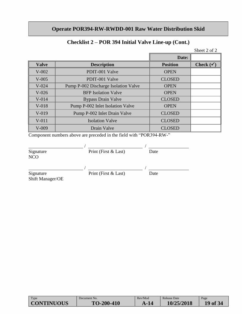
Checklist 2 – POR 394 Initial Valve Line-up (Cont.)
Sheet 2 of 2
Date:
Valve Description Position Check ()
V-002 PDIT-001 Valve OPEN
V-005 PDIT-001 Valve CLOSED
V-024 Pump P-002 Discharge Isolation Valve OPEN
V-026 BFP Isolation Valve OPEN
V-014 Bypass Drain Valve CLOSED
V-018 Pump P-002 Inlet Isolation Valve OPEN
V-019 Pump P-002 Inlet Drain Valve CLOSED
V-011 Isolation Valve CLOSED
V-009 Drain Valve CLOSED
Component numbers above are preceded in the field with “POR394-RW-”
/ /
Signature Print (First & Last) Date
NCO
/ /
Signature Print (First & Last) Date
Shift Manager/OE
Operate POR394-RW-RWDD-001 Raw Water Distribution Skid
Type
CONTINUOUS Document No.
TO-200-410 Rev/Mod
A-14 Release Date
10/25/2018 Page
20 of 34
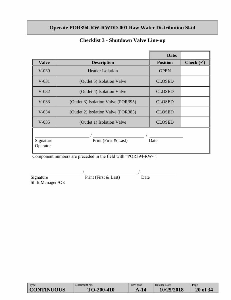
Checklist 3 - Shutdown Valve Line-up
Date:
Valve Description Position Check ()
V-030 Header Isolation OPEN
V-031 (Outlet 5) Isolation Valve CLOSED
V-032 (Outlet 4) Isolation Valve CLOSED
V-033 (Outlet 3) Isolation Valve (POR395) CLOSED
V-034 (Outlet 2) Isolation Valve (POR385) CLOSED
V-035 (Outlet 1) Isolation Valve CLOSED
/ /
Signature Print (First & Last) Date
Operator
Component numbers are preceded in the field with “POR394-RW-”.
/ /
Signature Print (First & Last) Date
Shift Manager /OE

Operate POR394-RW-RWDD-001 Raw Water Distribution Skid
Type
CONTINUOUS Document No.
TO-200-410 Rev/Mod
A-14 Release Date
10/25/2018 Page
21 of 34
Checklist 4 - Instrument Calibration Check
Date:
Instrument Nomenclature
(Recall)
Calibration (1)/
Functional Test
Next Due Date
Verified
Calibration Date
Check ()
POR394-RW-LIT-005
(ET-200446) Level Indicating Transmitter
POR394-RW-FE/FIT-015
(ET-200400) Flow Indicating Transmitter (POR394-RW-FIT-015)
POR394-RW-FE/FIT-016
(ET-200401) Flow Indicating Transmitter (POR394-RW-FIT-016)
POR394-RW-FIT-017
(ET-200402) Flow Indicating Transmitter
POR394-RW-FIT-018
(ET-200403) Flow Indicating Transmitter
POR394-RW-FIT-019
(ET-200404) Flow Indicating Transmitter
POR394-RW-PIT-010
(ET-200488) Pressure Indicating Transmitter
POR394-RW-PDIT-001
(ET-200465) Pressure Differential Indicating Transmitter
POR394-RW-TE/TIT-004
(ET-200489) Temperature Indicating Transmitter (POR394-RW-TIT-004)
(1) Calibration is defined as: Instrument's Preventive Maintenance is current, as checked on Preventive Maintenance System, or work
package.
Comments/Discrepancies:
Instrumentation and equipment has been verified for being within calibration due dates and/or all discrepancies/deficiencies have been
noted on this comment sheet.
/ /
Operator Signature Print (First & Last) Date
NOTE - If the instrument is being calibrated and is not within calibration, record in Comments/Discrepancies
Section. Put N/A in System Engineer signature block if no discrepancies are found.
/ /
OE Signature Print (First & Last) Date
/ /
System Engineer Signature Print (First & Last) Date

Operate POR394-RW-RWDD-001 Raw Water Distribution Skid
Type
CONTINUOUS Document No.
TO-200-410 Rev/Mod
A-14 Release Date
10/25/2018 Page
22 of 34
Checklist 5 - Instrument Operability Check
Sheet 1 of 2
Date:
Instrument Nomenclature Instrument
Location/Indication
Operable*
Y N
POR394-RW-RWDD-001
POR394-RW-TE/TIT-004
Temperature Element SKID and TIT-004 at HMI
POR394-RW-LIT-005
Water Tank Level Indicator SKID and LIT-005 at HMI
POR394-RW-FE/FIT-015
Flow Indicating Transmitter
FIT-015 at SKID and FIT-015
and FQI-015 at HMI
POR394-RW-PIT-010
Pressure Transmitter SKID and PIT-010 at HMI
POR394-RW-FIT-016
Flow Meter
FIT-016 at SKID and FIT-016
and FQI-016 at HMI
POR394-RW-FIT-017
Flow Meter
FIT-017 at SKID and FIT-017
and FQI-017 at HMI
POR394-RW-FIT-018
Flow Meter
FIT-018 at SKID and FIT-018
and FQI-018 at HMI
POR394-RW-FIT-019
Flow Meter
FIT-019 at SKID and FIT-019
and FQI-019 at HMI
POR394-RW-TK-001
POR394-RW-LI-006 Indicates TK-001 level
* Operable is defined as the following:
No Alarms are active on instrument (Except for expected alarms identified in
ARP-T-251-00033)
Instrument appears to be functioning normally (i.e., meters are active, etc.).
(Continued on Next Sheet)
Operate POR394-RW-RWDD-001 Raw Water Distribution Skid
Type
CONTINUOUS Document No.
TO-200-410 Rev/Mod
A-14 Release Date
10/25/2018 Page
23 of 34
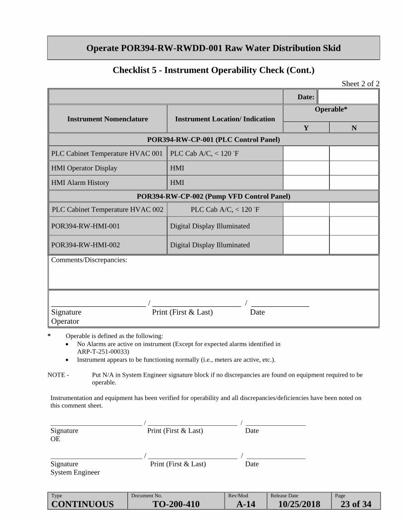
Checklist 5 - Instrument Operability Check (Cont.)
Sheet 2 of 2
Date:
Instrument Nomenclature Instrument Location/ Indication
Operable*
Y N
POR394-RW-CP-001 (PLC Control Panel)
PLC Cabinet Temperature HVAC 001 PLC Cab A/C, < 120 ◦F
HMI Operator Display HMI
HMI Alarm History HMI
POR394-RW-CP-002 (Pump VFD Control Panel)
PLC Cabinet Temperature HVAC 002 PLC Cab A/C, < 120 ◦F
POR394-RW-HMI-001 Digital Display Illuminated
POR394-RW-HMI-002 Digital Display Illuminated
Comments/Discrepancies:
/ /
Signature Print (First & Last) Date
Operator
* Operable is defined as the following:
No Alarms are active on instrument (Except for expected alarms identified in
ARP-T-251-00033)
Instrument appears to be functioning normally (i.e., meters are active, etc.).
NOTE - Put N/A in System Engineer signature block if no discrepancies are found on equipment required to be
operable.
Instrumentation and equipment has been verified for operability and all discrepancies/deficiencies have been noted on
this comment sheet.
/ /
Signature Print (First & Last) Date
OE
/ /
Signature Print (First & Last) Date
System Engineer

Operate POR394-RW-RWDD-001 Raw Water Distribution Skid
Type
CONTINUOUS Document No.
TO-200-410 Rev/Mod
A-14 Release Date
10/25/2018 Page
24 of 34
Checklist 6 – POR394 Upstream-Pre-Drain Valve Lineup
Date:
Valve Description Position Check ()
Upstream of Tank- Pre-Drain
V-036 RW Isolation Valve OPEN
V-006 Fill Isolation Valve OPEN
FLT-001 Strainer Valve OPEN (to one side)
V-002 PDIT-001 Upstream Isolation Valve OPEN
V-001 PDIT-001 Upstream Test Port OPEN
V-003 PDIT-001 Downstream Test Port OPEN
V-004 PDIT-001 Downstream Isolation Valve OPEN
V-005 PIDT-001 Vent Port OPEN
V-007 Strainer Drain OPEN
V-008 Strainer Drain OPEN
V-013 Level Gauge Isolation Valve OPEN
V-025 BFP Inlet Valve OPEN
V-026 BFP Outlet Valve OPEN
YV-002 Water Supply Shutoff Valve OPEN
/ /
Signature Print (First & Last) Date
Operator
Component numbers are preceded in the field with “POR394-RW-”.
/ /
Signature Print (First & Last) Date
Shift Manager /OE
Operate POR394-RW-RWDD-001 Raw Water Distribution Skid
Type
CONTINUOUS Document No.
TO-200-410 Rev/Mod
A-14 Release Date
10/25/2018 Page
25 of 34
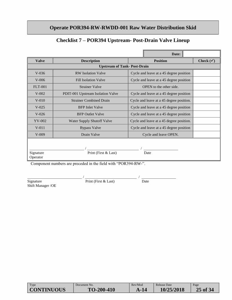
Checklist 7 – POR394 Upstream- Post-Drain Valve Lineup
Date:
Valve Description Position Check ()
Upstream of Tank- Post-Drain
V-036 RW Isolation Valve Cycle and leave at a 45 degree position
V-006 Fill Isolation Valve Cycle and leave at a 45 degree position
FLT-001 Strainer Valve OPEN to the other side.
V-002 PDIT-001 Upstream Isolation Valve Cycle and leave at a 45 degree position
V-010 Strainer Combined Drain Cycle and leave at a 45 degree position.
V-025 BFP Inlet Valve Cycle and leave at a 45 degree position
V-026 BFP Outlet Valve Cycle and leave at a 45 degree position
YV-002 Water Supply Shutoff Valve Cycle and leave at a 45 degree position.
V-011 Bypass Valve Cycle and leave at a 45 degree position
V-009 Drain Valve Cycle and leave OPEN.
/ /
Signature Print (First & Last) Date
Operator
Component numbers are preceded in the field with “POR394-RW-”.
/ /
Signature Print (First & Last) Date
Shift Manager /OE

Operate POR394-RW-RWDD-001 Raw Water Distribution Skid
Type
CONTINUOUS Document No.
TO-200-410 Rev/Mod
A-14 Release Date
10/25/2018 Page
26 of 34
Checklist 8 - POR394 Downstream Pre-Drain Valve Lineup
Date:
Valve Description Position Check ()
Downstream Pre-Drain
V-017 Low Point Drain OPEN
V-016 Pump Isolation Valve OPEN
V-015 Return Line Drain OPEN
V-018 Pump Isolation Valve OPEN
V-014 Return Line Drain OPEN
V-023 Pump Downstream Isolation Valve OPEN
V-024 Pump Downstream Isolation Valve OPEN
V-022 Extended Return Line Isolation OPEN
V-021 PIT-010 Isolation OPEN
V-020 PIT-010 Vent OPEN
YV-003 Discharge Shutoff OPEN
V-030 Header Isolation OPEN
V-031 Isolation Valve OPEN
V-032 Isolation Valve OPEN
V-012 Level Gauges Drain Valve OPEN
V-035 Isolation Valve OPEN
/ /
Signature Print (First & Last) Date
Operator
Component numbers are preceded in the field with “POR394-RW-”.
/ /
Signature Print (First & Last) Date
Shift Manager /OE

Operate POR394-RW-RWDD-001 Raw Water Distribution Skid
Type
CONTINUOUS Document No.
TO-200-410 Rev/Mod
A-14 Release Date
10/25/2018 Page
27 of 34
Checklist 9 - POR394 Downstream- Post-Drain Valve Lineup
Date:
Valve Description Position Check ()
Downstream of Tank- Post-Drain
V-017 Low Point Drain Cycle and leave OPEN
V-016 Pump Isolation Valve Cycle and leave at a 45 degree position
V-015 Return Line Drain Cycle and leave OPEN
V-018 Pump Isolation Valve Cycle and leave at a 45 degree position
V-014 Return Line Drain Cycle and leave OPEN
V-023 Pump Downstream Isolation Valve Cycle and leave OPEN
V-024 Pump Downstream Isolation Valve Cycle and leave OPEN
V-022 Extended Return Line Isolation Cycle and leave OPEN
V-021 PIT-010 Isolation Cycle and leave at a 45 degree position
V-020 PIT-010 Vent Cycle and leave OPEN.
YV-003 Discharge Shutoff Cycle and leave at a 45 degree position
V-030 Header Isolation Cycle and leave at a 45 degree position
V-031 Isolation Valve Cycle and leave at a 45 degree position
V-032 Isolation Valve Cycle and leave at a 45 degree position
V-012 Level Gauges Drain Valve OPEN
V-035 Isolation Valve CLOSED
/ /
Signature Print (First & Last) Date
Operator
Component numbers are preceded in the field with “POR394-RW-”.
/ /
Signature Print (First & Last) Date
Shift Manager /OE

Operate POR394-RW-RWDD-001 Raw Water Distribution Skid
Type
CONTINUOUS Document No.
TO-200-410 Rev/Mod
A-14 Release Date
10/25/2018 Page
28 of 34
Figure 1 – Main Overview
Operate POR394-RW-RWDD-001 Raw Water Distribution Skid
Type
CONTINUOUS Document No.
TO-200-410 Rev/Mod
A-14 Release Date
10/25/2018 Page
29 of 34
Figure 2 – HMI Display Screen

Operate POR394-RW-RWDD-001 Raw Water Distribution Skid
Type
CONTINUOUS Document No.
TO-200-410 Rev/Mod
A-14 Release Date
10/25/2018 Page
30 of 34
Figure 3 - Alarms

Operate POR394-RW-RWDD-001 Raw Water Distribution Skid
Type
CONTINUOUS Document No.
TO-200-410 Rev/Mod
A-14 Release Date
10/25/2018 Page
31 of 34
Figure 4 – Analog Input Trend 1

Operate POR394-RW-RWDD-001 Raw Water Distribution Skid
Type
CONTINUOUS Document No.
TO-200-410 Rev/Mod
A-14 Release Date
10/25/2018 Page
32 of 34
Figure 5 - POR394-RW-RWDD-001 RWDD Diagram
A
PDIT001V-001
NCV-003
NC
V-002
NO
V-004
NO
V-005
NC
BPF-001
V-006
V-008DRAIN
V-010DRAIN
V-007DRAIN
V-025 V-026
FLT-001
SUPPLY
FROM 4" RW 100 M37
MANUAL
OVERRIDE
FAIL
CLOSED
MANUAL
OVERRIDE
MODULATED
V-011
MOV001 LCV
001
Operate POR394-RW-RWDD-001 Raw Water Distribution Skid
Type
CONTINUOUS Document No.
TO-200-410 Rev/Mod
A-14 Release Date
10/25/2018 Page
33 of 34
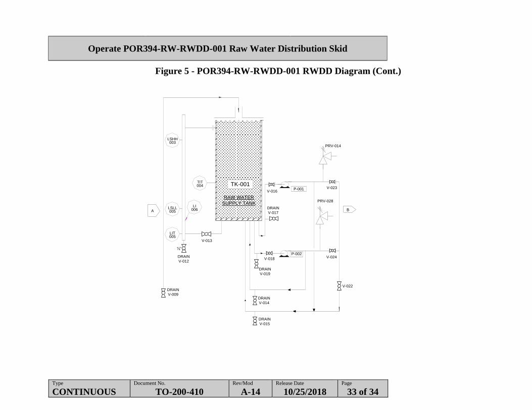
Figure 5 - POR394-RW-RWDD-001 RWDD Diagram (Cont.)
A B
P-001
PRV-014
V-023V-016
PRV-028
DRAIN
V-017
DRAIN
V-019
V-018
P-002V-024
V-022
DRAIN
V-014
DRAIN
V-015
DRAIN
V-012
V-013
DRAIN
V-009
TK-001
RAW WATER
SUPPLY TANK
½”
LSHH003
LSLL005
LI006
TIT004
LIT005

Operate POR394-RW-RWDD-001 Raw Water Distribution Skid
Type
CONTINUOUS Document No.
TO-200-410 Rev/Mod
A-14 Release Date
10/25/2018 Page
34 of 34
Figure 5 - POR394-RW-RWDD-001 RWDD Diagram (Cont.)
B
TO POR385
TO POR395
V-035
1"HC-002
OUTLET 1
3"HC-003
OUTLET 2
Z C2
V-034
3"HC-004
OUTLET 3
3"HC-005
OUTLET 4
3"HC-006
OUTLET 5
V-033
V-032
V-031
FIT019
FIT018
FIT017
FIT016
V-030
MANUALOVERRIDE
FAILCLOSED
MOV002
FIT015
PI013PRV-027
PIT010
V-020NC
V-021NO
V-038
2"HC-008
OUTLET 6


