Download - Offshore Civil Engineering Structures

Geophysical Applications in Offshore Civil Engineering Structures
Vikas B.Tech. Civil 2nd Year 12113117 ES-201
You created this PDF from an application that is not licensed to print to novaPDF printer (http://www.novapdf.com)
1 | P a g e
Contents
Topics Page Number
Introduction 2
Review of Literature 3
Gap in Motivation 4
Objective The Offshore Environment
5
Site Investigation
1. Desk Survey
2. Geophysical Survey
3. Geotechnical Survey
8
Offshore Structures and Geotechnical Considerations
14
Conclusions 18
References 19
You created this PDF from an application that is not licensed to print to novaPDF printer (http://www.novapdf.com)
2 | P a g e
Introduction
Offshore geotechnical engineering is a sub-field of geotechnical engineering. It is concerned with foundation design, construction, maintenance, and de-commissioning for human-made structures in the sea. Oil platforms, artificial islands and submarine pipelines are examples of such structures.
The seabed has to be able to withstand the weight of these structures and the applied loads. Geohazards must also be taken into account.
The need for offshore developments stems from a gradual depletion of hydrocarbon reserves onshore or near the coastlines, as new fields are being developed at greater distances offshore and in deeper water, with a corresponding adaptation of the offshore site investigations.
Today, there are more than 7,000 offshore platforms operating at a water depth up to and exceeding 2000 m. A typical field development extends over tens of square kilometers, and may comprise several fixed structures, infield flow lines with an export pipeline either to the shoreline or connected to a regional trunk line.
You created this PDF from an application that is not licensed to print to novaPDF printer (http://www.novapdf.com)
3 | P a g e
Review of Literature
Trends in Offshore Design Practice
General
Enormous costs of site investigation (> $1 million/borehole)
Focus more on capacity than deformations or stiffness
Strength determination: issues of anisotropy, degradation due to cyclic
loading, sampling challenge in deep water soft clays
Environmental loading more significant than for onshore –yield
envelopes replacing bearing capacity factors
Shallow water
Driven pipe piles – extension of onshore practice, but high capacity
Carbonate sediments – alternative foundations to driven piles
Skirted ‘gravity base’ foundations instead of (onshore) deep basements
Innovative use of short suction caissons in dense sands
Deep water
TLPs: Special attention to cyclic loading on tension piles
Anchoring technology (drag anchors, suction caissons etc)
Geohazards and pipelines
You created this PDF from an application that is not licensed to print to novaPDF printer (http://www.novapdf.com)

4 | P a g e
Gap in Motivation
A large part of this paper focuses on the following:
Offshore environment characteristics.
Offshore site investigation.
Sampling and In situ laboratory testing.
Various types of offshore structures.
Soil and seabed characteristics.
Considerations on basis of geohazards at the site.
Bringing out geophysics as the core in development of offshore structures.
You created this PDF from an application that is not licensed to print to novaPDF printer (http://www.novapdf.com)
5 | P a g e
Objective
The focus of this report is to highlight various geotechnical practices in construction of offshore structures of various types.
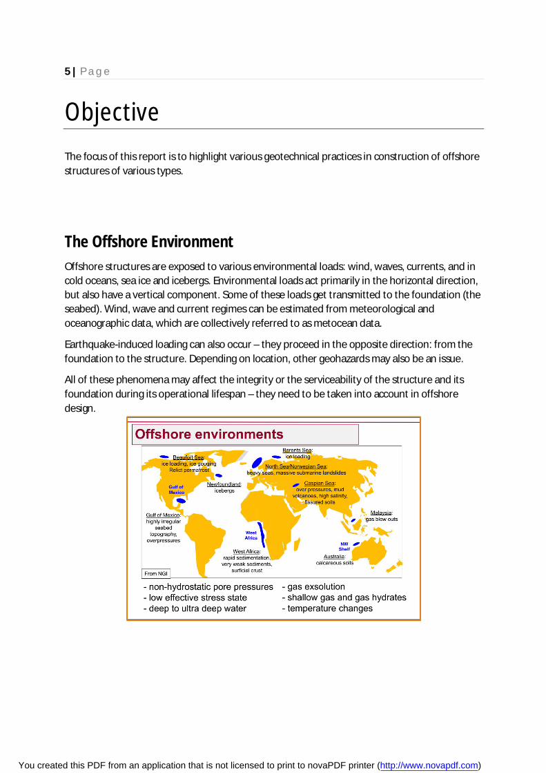
The Offshore Environment Offshore structures are exposed to various environmental loads: wind, waves, currents, and in cold oceans, sea ice and icebergs. Environmental loads act primarily in the horizontal direction, but also have a vertical component. Some of these loads get transmitted to the foundation (the seabed). Wind, wave and current regimes can be estimated from meteorological and oceanographic data, which are collectively referred to as metocean data.
Earthquake-induced loading can also occur – they proceed in the opposite direction: from the foundation to the structure. Depending on location, other geohazards may also be an issue.
All of these phenomena may affect the integrity or the serviceability of the structure and its foundation during its operational lifespan – they need to be taken into account in offshore design.
You created this PDF from an application that is not licensed to print to novaPDF printer (http://www.novapdf.com)
6 | P a g e
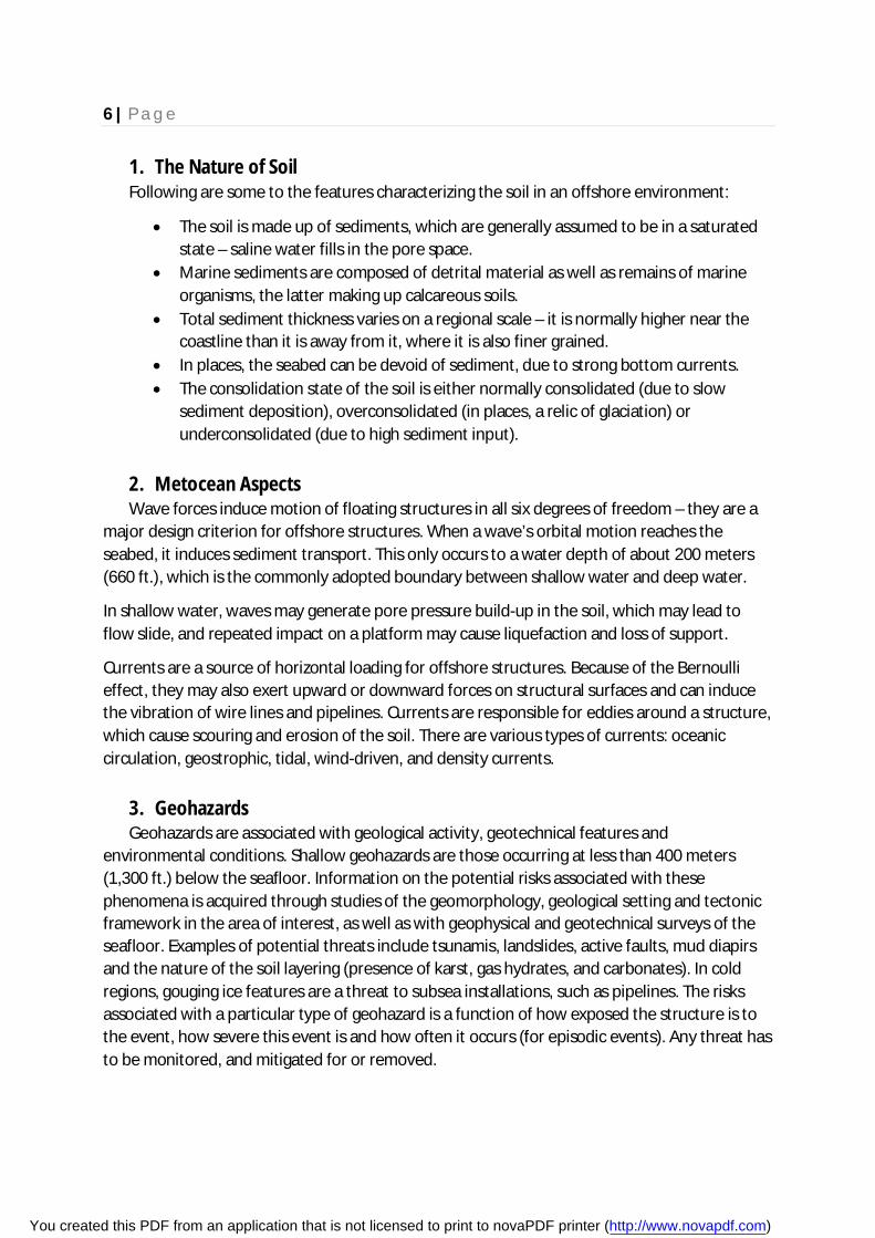
1. The Nature of Soil Following are some to the features characterizing the soil in an offshore environment:
The soil is made up of sediments, which are generally assumed to be in a saturated state – saline water fills in the pore space.
Marine sediments are composed of detrital material as well as remains of marine organisms, the latter making up calcareous soils.
Total sediment thickness varies on a regional scale – it is normally higher near the coastline than it is away from it, where it is also finer grained.
In places, the seabed can be devoid of sediment, due to strong bottom currents. The consolidation state of the soil is either normally consolidated (due to slow
sediment deposition), overconsolidated (in places, a relic of glaciation) or underconsolidated (due to high sediment input).
2. Metocean Aspects Wave forces induce motion of floating structures in all six degrees of freedom – they are a
major design criterion for offshore structures. When a wave’s orbital motion reaches the seabed, it induces sediment transport. This only occurs to a water depth of about 200 meters (660 ft.), which is the commonly adopted boundary between shallow water and deep water.
In shallow water, waves may generate pore pressure build-up in the soil, which may lead to flow slide, and repeated impact on a platform may cause liquefaction and loss of support.
Currents are a source of horizontal loading for offshore structures. Because of the Bernoulli effect, they may also exert upward or downward forces on structural surfaces and can induce the vibration of wire lines and pipelines. Currents are responsible for eddies around a structure, which cause scouring and erosion of the soil. There are various types of currents: oceanic circulation, geostrophic, tidal, wind-driven, and density currents.
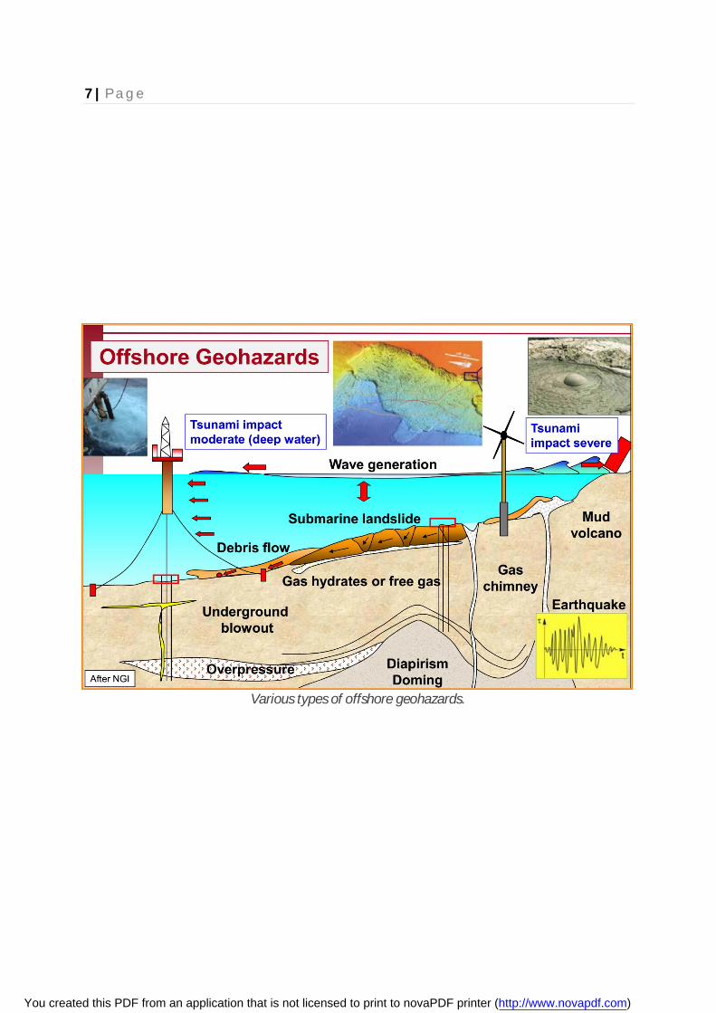
3. Geohazards Geohazards are associated with geological activity, geotechnical features and
environmental conditions. Shallow geohazards are those occurring at less than 400 meters (1,300 ft.) below the seafloor. Information on the potential risks associated with these phenomena is acquired through studies of the geomorphology, geological setting and tectonic framework in the area of interest, as well as with geophysical and geotechnical surveys of the seafloor. Examples of potential threats include tsunamis, landslides, active faults, mud diapirs and the nature of the soil layering (presence of karst, gas hydrates, and carbonates). In cold regions, gouging ice features are a threat to subsea installations, such as pipelines. The risks associated with a particular type of geohazard is a function of how exposed the structure is to the event, how severe this event is and how often it occurs (for episodic events). Any threat has to be monitored, and mitigated for or removed.
You created this PDF from an application that is not licensed to print to novaPDF printer (http://www.novapdf.com)
7 | P a g e
Various types of offshore geohazards.
You created this PDF from an application that is not licensed to print to novaPDF printer (http://www.novapdf.com)

8 | P a g e
Site Investigation
Offshore site investigations are mainly divided into three parts:
1. Desk Study In this phase, which may take place over a period of several months (depending on project
size), information is gathered from various sources, including reports, papers and databases, with the purpose of evaluating risks, assessing design options and planning the subsequent phases. Bathymetry, regional geology, potential geohazards, seabed obstacles and metocean data are some of the information that are sought after during that phase.
2. Geophysical Surveys Geophysical surveys can be used for various purposes. One is to study the bathymetry in the
location of interest and to produce an image of the seafloor (irregularities, objects on the seabed, lateral variability, ice gouges etc.). Seismic refraction surveys can be done to obtain information on shallow seabed stratigraphy – it can also be used to locate material such as sand and gravel for use in the construction of artificial islands. Geophysical surveys are conducted from a research vessel equipped with sonar devices and related equipment, such as single-beam and multibeam echosounders, side-scan sonars, ‘towfish’ and remotely operated vehicles (ROVs). For the sub-bottom stratigraphy, the tools used include boomers, sparkers, pingers and chirp. Geophysical surveys are normally required before conducting the geotechnical surveys; in larger projects, these phases may be interwoven.
A 3-D image of the Monterey Canyon system, an example of what can be obtained from multibeam echosounders.
You created this PDF from an application that is not licensed to print to novaPDF printer (http://www.novapdf.com)
9 | P a g e
3. Geotechnical Surveys Geotechnical surveys involve a combination of sampling, drilling, in situ testing as well as
laboratory soil testing both onshore and offshore. They serve to ground truth the results of the geophysical investigations; they also provide a detailed account of the seabed stratigraphy and soil engineering properties. Depending on water depth and metocean conditions, geotechnical surveys may be conducted from a dedicated geotechnical drillship, a semi-submersible, a jackup rig, a large hovercraft or other means. They are done at a series of specific locations, while the vessel maintains a constant position. Dynamic positioning and mooring with four-point anchoring systems are used for that purpose.
Shallow penetration geotechnical surveys may include soil sampling of the seabed surface or in situ mechanical testing. They are used to generate information on the physical and mechanical properties of the seabed. They extend to the first few meters below the mudline. Surveys done to these depths, which may be conducted at the same time as the shallow geophysical survey, may suffice if the structure to be deployed at that location is relatively light. These surveys are also useful for planning subsea pipeline routes.
The purpose of deep penetration geotechnical surveys is to collect information on the seabed stratigraphy to depths extending up to a few 100 meters below the mudline. These surveys are done when larger structures are planned at these locations. Deep drill holes make require a few days during which the drilling unit has to remain exactly in the same position.
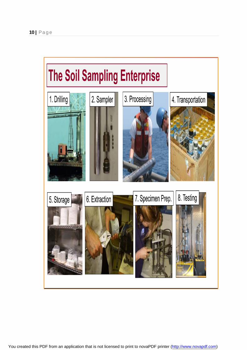
Sampling and Drilling Seabed surface sampling can be done with a grab sampler and with a box corer. The latter provides undisturbed specimens, on which testing can be conducted, for instance, to determine the soil’s relative density, water content and mechanical properties. Sampling can also be achieved with a tube corer, either gravity-driven, or that can be pushed into the seabed by a piston or by means of a vibration system (a device called a vibrocorer).
You created this PDF from an application that is not licensed to print to novaPDF printer (http://www.novapdf.com)
10 | P a g e
You created this PDF from an application that is not licensed to print to novaPDF printer (http://www.novapdf.com)
11 | P a g e
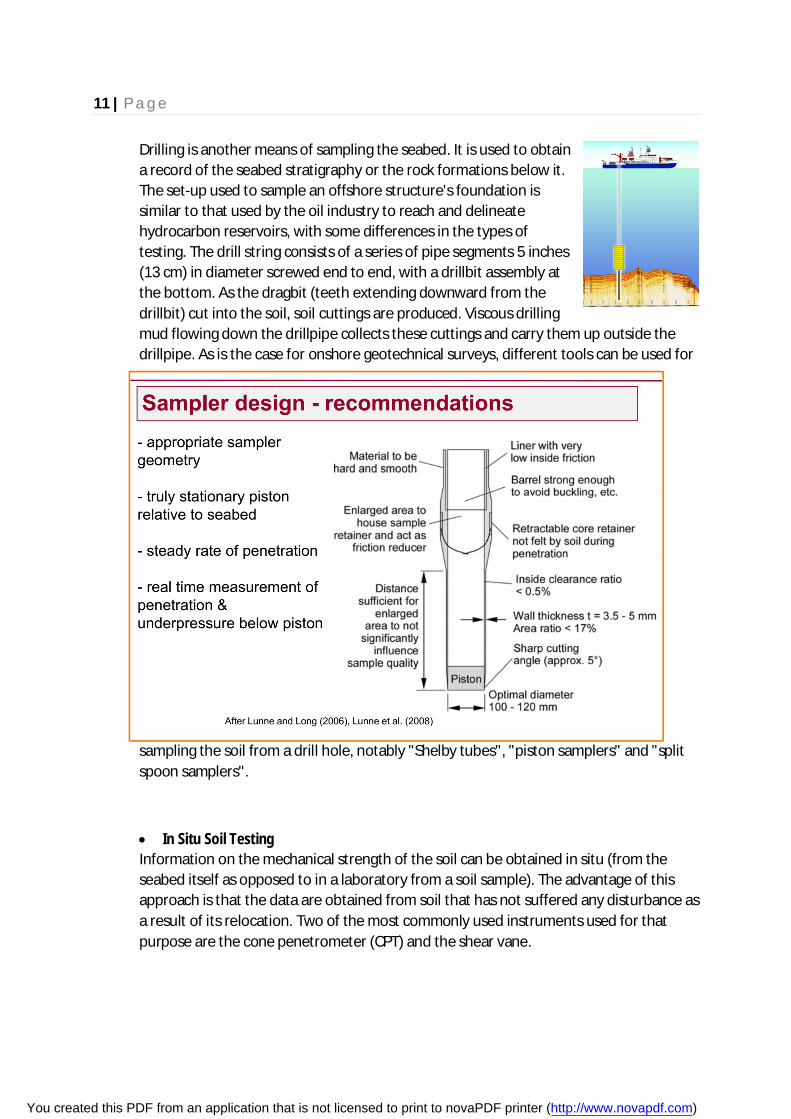
Drilling is another means of sampling the seabed. It is used to obtain a record of the seabed stratigraphy or the rock formations below it. The set-up used to sample an offshore structure's foundation is similar to that used by the oil industry to reach and delineate hydrocarbon reservoirs, with some differences in the types of testing. The drill string consists of a series of pipe segments 5 inches (13 cm) in diameter screwed end to end, with a drillbit assembly at the bottom. As the dragbit (teeth extending downward from the drillbit) cut into the soil, soil cuttings are produced. Viscous drilling mud flowing down the drillpipe collects these cuttings and carry them up outside the drillpipe. As is the case for onshore geotechnical surveys, different tools can be used for
sampling the soil from a drill hole, notably "Shelby tubes", "piston samplers" and "split spoon samplers".
In Situ Soil Testing Information on the mechanical strength of the soil can be obtained in situ (from the seabed itself as opposed to in a laboratory from a soil sample). The advantage of this approach is that the data are obtained from soil that has not suffered any disturbance as a result of its relocation. Two of the most commonly used instruments used for that purpose are the cone penetrometer (CPT) and the shear vane.
You created this PDF from an application that is not licensed to print to novaPDF printer (http://www.novapdf.com)

12 | P a g e
The CPT is a rod-shaped tool whose end has the shape of a cone with a known apex angle (e.g. 60 degrees). As it is pushed into the soil, the resistance to penetration is measured, thereby providing an indication of soil strength. A sleeve behind the cone allows the independent determination of the frictional resistance. Some cones are also able to measure pore water pressure. The shear vane test is used to determine the undrained shear strength of soft to medium cohesive soils. This instrument usually consists of four plates welded at 90 degrees from each other at the end of a rod. The rod is then inserted into the soil and a torque is applied to it so as to achieve a constant rotation rate. The torque resistance is measured and an equation is then used to determine the undrained shear strength (and the residual strength), which takes into account the vane’s size and geometry.
You created this PDF from an application that is not licensed to print to novaPDF printer (http://www.novapdf.com)
13 | P a g e
You created this PDF from an application that is not licensed to print to novaPDF printer (http://www.novapdf.com)
14 | P a g e
Offshore Structures and Geotechnical Considerations
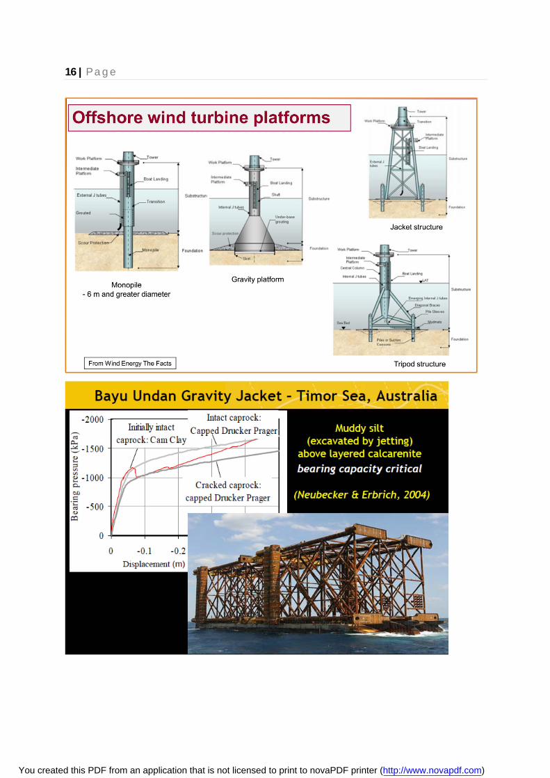
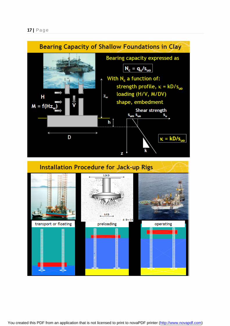
Offshore structures are mainly represented by platforms, notably jackup rigs, steel jacket structures and gravity-based structures. The nature of the seabed has to be taken into account when planning these developments. For instance, a gravity-based structure typically has a very large footprint and is relatively buoyant (because it encloses a large open volume). Under these circumstances, vertical loading of the foundation may not be as significant as the horizontal loads exerted by wave actions and transferred to the seabed. In that scenario, sliding could be the dominant mode of failure. A more specific example is that of the Woodside "North Rankin A" steel jacket structure offshore Australia. The shaft capacity for the piles making up each of the structure's legs was estimated on the basis of conventional design methods, notably when driven into siliceous sands. But the soil at that site was a lower capacity calcareous sand. Costly remediation measures were required to correct this oversight.
Proper seabed characterization is also required for mooring systems. For instance, the design and installation of suction piles has to take into account the soil properties, notably its undrained shear strength. The same is true for the installation and capacity assessment of plate anchors.
You created this PDF from an application that is not licensed to print to novaPDF printer (http://www.novapdf.com)
15 | P a g e
You created this PDF from an application that is not licensed to print to novaPDF printer (http://www.novapdf.com)
16 | P a g e
You created this PDF from an application that is not licensed to print to novaPDF printer (http://www.novapdf.com)
17 | P a g e
You created this PDF from an application that is not licensed to print to novaPDF printer (http://www.novapdf.com)

18 | P a g e
Conclusions
Exploiting hydrocarbon resources in deep-water poses an increasing challenge, especially site characterization of very soft sediments. Calibration of in situ test results by variably disturbed laboratory strengths is a losing strategy. Strive for improved design basis with foundation and anchor performance related directly to in situ penetration resistance. Cost-benefits for improvement in design approaches for conventional shallow and pile foundations. Simple and robust anchoring systems a priority. Geophysical and Geotechnical practices are at the heart of designing the offshore structures like oil rigs, wind farms, and piles. The sonar mapping, surveying and mechanical analysis of the seabed are done in every such development work. Offshore Geotechnical Engineering offers major challenges and fantastic opportunities for development of innovative solutions.
You created this PDF from an application that is not licensed to print to novaPDF printer (http://www.novapdf.com)

19 | P a g e
References
Offshore Geotechnical Engineering; Richard Dean, E.T.
Recommended Site Investigation Practices for Offshore Energy Systems; DeGroot, Don J., University of Massachusetts, USA
Challenges of Offshore Geotechnical Engineering; Centre for Offshore Foundation Systems, University of Western Australia
Offshore Engineering; www.imc.src.ku.ac.th/personnel/file_subject/20101122955391.pdf
Construction of marine and offshore structures; Gerwick B.C.
Wikipedia: http://en.wikipedia.org/wiki/Offshore_geotechnical_engineering
You created this PDF from an application that is not licensed to print to novaPDF printer (http://www.novapdf.com)


