
Cold Room ControlInstallation and Operating Instructions
March 2013 / Bulletin 100-50-4.1
Controller v. A

Page 2 – Bulletin 100-50-4.1
FOR USE ON REFRIGERATION and/or AIR CONDITIONING SYSTEMS ONLY
For more information about our products visit us at www.sporlan.com.Bulletin 100-50-4.1, March 2013 supersedes SD-302M, November 2011 and all prior publications.
1. Installation . . . . . . . . . . . . . . . . . . . . . . . 3 Cold Room Control . . . . . . . . . . . . . . . . 3 Sensors . . . . . . . . . . . . . . . . . . . . . . . . . 4 Relays . . . . . . . . . . . . . . . . . . . . . . . . . . 5 Valves . . . . . . . . . . . . . . . . . . . . . . . . . . 5
2. System Setup . . . . . . . . . . . . . . . . . . . . 6 Single Evaporator Setup . . . . . . . . . . . . 6 Multiple Evaporator Setup . . . . . . . . . . . 7
3. System Startup . . . . . . . . . . . . . . . . . . . 7
4. System Operation . . . . . . . . . . . . . . . . . 8 Refrigeration . . . . . . . . . . . . . . . . . . . . . 8 Defrost. . . . . . . . . . . . . . . . . . . . . . . . . . 8 Operational Features . . . . . . . . . . . . . . . 9 Operating Modes. . . . . . . . . . . . . . . . . . 9 System Menus. . . . . . . . . . . . . . . . . . . 10
5. Communications . . . . . . . . . . . . . . . . . 11 Private Controller Network . . . . . . . . . . 11 Modbus Network. . . . . . . . . . . . . . . . . 12
6. PID Tuning. . . . . . . . . . . . . . . . . . . . . . 12
7. Troubleshooting. . . . . . . . . . . . . . . . . . 12 Cold Room Control . . . . . . . . . . . . . . . 13 Sensors . . . . . . . . . . . . . . . . . . . . . . . . 13 Controller Replacement . . . . . . . . . . . . 14 Communication Error. . . . . . . . . . . . . . 14 Alarms . . . . . . . . . . . . . . . . . . . . . . . . . 14
8. System Specifications . . . . . . . . . . . . . 14
APPENDIX A Parameter Definitions. . . . . . . . . . . . . . 15
APPENDIX B Troubleshooting Chart . . . . . . . . . . . . . 17
APPENDIX C 3K Temperature Sensor Specifications . . 18
APPENDIX D CRC Modbus Map . . . . . . . . . . . . . . . . 19
APPENDIX E CRC Wiring Diagram . . . . . . . . . . . . . . 23
APPENDIX F Accessories . . . . . . . . . . . . . . . . . . . . . 23
APPENDIX G System Schematic . . . . . . . . . . . . . . . . 24
APPENDIX H CRC Board Indicator Lights . . . . . . . . . 25
APPENDIX I Maintenance Log Sheet . . . . . . . . . . . . 26
⚠WARNING – USER RESPONSIBILITY
Failure or improper selection or improper use of the products described herein or related items can cause death, personal injury and property damage.
This document and other information from Parker Hannifin Corporation, its subsidiaries and authorized distributors provide product or system options for further investigation by users having technical expertise.
The user, through its own analysis and testing, is solely responsible for making the final selection of the system and components and assuring that all performance, endurance, maintenance, safety and warning requirements of the application are met. The user must analyze all aspects of the application, follow applicable industry standards, and follow the information concerning the product in the current product catalog and in any other materials provided from Parker or its subsidiaries or authorized distributors.
To the extent that Parker or its subsidiaries or authorized distributors provide component or system options based upon data or specifications provided by the user, the user is responsible for determining that such data and specifications are suitable and sufficient for all applications and reasonably foreseeable uses of the components or systems.
For safety information see the Safety Guide at www.parker.com/safety or call 1-800-CParker. OFFER OF SALE The items described in this document are hereby offered for sale by Parker Hannifin Corporation, its subsidiaries or its authorized distributors. This offer and its acceptance are governed by the provisions stated in the detailed “Offer of Sale” available at www.parker.com.
Contents

Bulletin 100-50-4.1 – Page 3
1. InstallationTOOLS REQUIRED:• Small flat screwdriver for terminal connections• Cordless screwdriver• Phillips and flat screwdrivers• Needle-nose pliers• Wire cutters• Scotch-BriteTM pad • Two #10 self-tapping screws to mount SnapTrack panel
COLD ROOM CONTROLThe Cold Room Control should be installed in an indoor or protected location, away from electromagnetic
IntroductionThe Sporlan Cold Room Control (CRC) is a microprocessor-based system designed to pre-cisely control refrigeration evaporators in walk-in coolers and freezers. It accurately controls refriger-ant flow and provides a single point of reference for all control components. By monitoring pressure and temperatures, the CRC controls evaporator temperature more accurately and consistently than mechanical thermostatic expansion valves. In addi-tion to superheat and room temperature control, the CRC is configured to control evaporator fans, the liquid line solenoid, defrost heaters, and defrost schedules. Valves and sensors may be purchased from Sporlan.
Features• Integrated digital temperature control
•Pressure/Temperature Superheat control
•Networked controllers for multiple evaporators
• “One push” setup for slave controllers
•Defrost scheduling
•Compressor protection algorithm
•3-digit LED display
•Modbus® communication for remote monitoring
•Removeable connectors for quick and easy installation
•Four temperature inputs (Sporlan surface or air sensors)
•One pressure input (Sporlan transducer)
•One digital input (for external switch or relay)
•Real-time clock
interference. Place it in an easily viewed area where it can be used as a digital thermometer. It can be installed near the evaporator or by the entrance to the refrigerated space. Waterproof connections and an enclosure must be used in wet areas.
1. Use self-tapping #10 screws to mount the SnapTrack panel flush on a flat surface. To leave enough working space, the suggested mounting area is 10 inches high and 6 inches wide. The minimum depth is 2.5 inches. See Figure 1.
2. Do not power up the CRC until all system components are installed (later in this section) and the system is ready for the setup procedure. See Section 2.
For multiple evaporator systems, install one CRC per evaporator.
The CRC board has removeable terminals for most con-nections. Use the screw terminals on the board (3.5 in-lbs maximum torque) or unplug them and make the connec-tions off of the board. Follow local wiring regulations. The wiring schematic is for illustration only, Sporlan is not responsibile for incorrect wiring.
10”254 mm
6”152 mm
Figure 1 - Recommended Mounting Clearance

Page 4 – Bulletin 100-50-4.1
Temperature sensors should be mounted at either 4 or 8 o’clock, on a free-draining horizontal line.
Figure 2 - Suction Outlet Temperature Sensor Position
WARNING: Use caution when working around high voltage components. Safety covers should be used for personal safety on high voltage panels.
NOTE: The Sporlan CRC refrigeration controller should be installed only by a qualified professional. All other sys-tem components (valves and sensors) should be supplied by Sporlan to ensure compatibility and proper operation.
SENSORSThe Sporlan CRC uses the input from one pressure trans-ducer and three 3K temperature sensors to control super-heat, defrost, and room temperature. Sensor cables may be extended to 100 ft. (30.5 m) using 18 gauge shielded twisted pair cable and ScotchlokTM UR connectors for long-term integrity.
WARNING: Route and secure sensor cables away from hot surfaces, high voltage lines, and moving components.
See Appendix G - System Schematic for sensor locations, and refer to Sporlan’s sensor installation instructions, SD-245, available at www.sporlanonline.com.
Pressure TransducerThe pressure transducer sends suction pressure data to the controller. Suction pressure and suction outlet tempera-ture is used by the controller to calculate superheat. The CRC will automatically select a pressure transducer range based on the refrigerant selected. The transducer range can also be set manually in the Programming Menu.
Refer to Appendix G - System Schematic, page 24.
1. Locate or install a ¼” SAE access fitting on the suction line near the outlet of the evaporator. Mount it at 12 o’clock on a free-draining horizontal line to minimize oil trapping.
WARNING: Remove pressurized refrigerant from the line before installing the fitting.
2. Install the transducer, tighten it to 8 ft-lbs, and check for leaks. Do not use a gasket or a washer.
WARNING: For safety, ensure that the correct Schrader core is installed in the access fitting and use caution when removing Schrader cap / install-ing transducer to avoid any escaping refrigerant.
3. Connect the pressure transducer cable to the transducer.4. Connect the transducer leads to the three terminals
labeled “CN3” on the board. See Table 1 - Pressure Transducer Wire Colors.
5. After startup (Section 3), use a gauge set to verify proper pressure reading to the CRC. An incorrect or improperly installed Schrader core can cause errone-ous pressure readings.
6. Check for leaks after the system is in operation.
Table 1 – Pressure Transducer Wire Colors
CRC TERMINAL TRANSDUCER CABLE
+ Red Black
- Black Green
S Green White
Suction Outlet Temperature Sensor1. Per Appendix G - System Schematic, page 24, the
temperature sensor should be installed 10-14 inches from the evaporator outlet on a free-draining hori-zontal line. Minimize the distance from the pressure transducer.
2. Use Scotch-BriteTM to clean the copper line at the area of installation. Remove oxides and dirt to increase sensor accuracy.
3. Fasten the temperature sensor to the copper line in the orientation shown in Figure 2.
4. Connect sensor leads to the terminals labeled “Evap. Out” on the CRC board as shown in Appendix E - CRC Wiring Diagram. The leads are not polarized.
5. Wrap temperature sensor and copper line with foam insulation to minimize ambient temperature effects. See Figure 3.
Defrost Termination Temperature Sensor1. Per Appendix G - System Schematic, page 24, position
the Defrost Termination sensor on the coldest point on the evaporator coil. This location is typically the final return bend in the coil before entering the suc-tion manifold. Consult the coil manufacturer for the best location for the Defrost Termination sensor.
2. Connect sensor wires to the terminals labeled “Def-Tmp” on the CRC board as shown in Appendix E - CRC Wiring Diagram. The sensor leads are not polarized.
WARNING: Ensure that “Suction” and “Termination” temperature sensor locations are not reversed. Severe system damage may occur if these two sensor locations are interchanged.

Bulletin 100-50-4.1 – Page 5
Room Temperature Sensor1. Mount the Room or Box Temperature sensor in the
area to be controlled. If the room sensor is mounted in the return air, ensure sensor is greater than 4” away from the evaporator coil surface.
2. Connect sensor wires to the terminals labeled “Room. Tmp” on the CRC board as shown in Appendix E - CRC Wiring Diagram. The sensor leads are not polarized.
Auxiliary Temperature Sensor1. Mount the optional Auxiliary Temperature sensor in
any desired location to monitor additional tempera-tures such as food product temperature, additional case areas, etc. Unlike the other sensors, it is not nec-cessary for system function.
2. Connect sensor leads to the terminals labeled “Aux-Temp” on the CRC board as shown in Appendix E - CRC Wiring Diagram. The leads are not polarized.
NOTE: 3K sensors have approximately 2.8kΩ at 80°F measured across the sensor wires.
RELAYSThe defrost heater relay and fan relay are both rated for 30A inductive inrush loads and 40A resistive loads; maxi-mum 240VAC. The board also has solid state relays for the liquid line solenoid and an external alarm. The alarm relay is rated at 6A resistive load; maximum 277VAC. The liquid line solenoid relay is rated at 3A resistive load; max-imum 400VAC.
If the heater relay or fan relay on the board are used to pilot an external contactor, snubbers or appropriate arc suppression devices should be used. This will eliminate noise that could interfere with the operation of the CRC.
Evaporator Fan Relay1. Crimp two 1/4” female terminals to 18 gauge wires
that will be used on the relay. 2. Connect the L1 (hot) lead from the power supply to
the common (COM) terminal on the fan relay.
3. Connect the normally closed (N.C.) relay terminal to one terminal on the fan.
4. Connect the L2 (neutral) leg of the power supply to the other terminal on the fan.
Defrost Heater Relay1. Crimp two 1/4” female terminals to 18 gauge wires
that will be used on the relay. 2. Connect the L1 (hot) lead from the power supply to
the common (COM) terminal on the heater relay.3. Connect the normally open (N.O.) relay terminal to
one terminal on the heater.4. Connect the L2 (neutral) leg of the power supply to
the other terminal on the heater.
For electric defrost, the heater will be OFF during nor-mal refrigeration and ON during defrost as set by menu options.
Alarm Relay1. Crimp two 1/4” female terminals to 18 gauge wires
that will be used on the relay. 2. Connect the L1 (hot) lead from the power supply to
the Alarm terminal labeled “CN5” on the board. 3. Connect one end of an extension lead to the Alarm
terminal labeled “CN11” on the board. Connect the other end to one terminal or lead on the alarm.
4. Connect the L2 (neutral) leg of the power supply to the other lead or terminal on the alarm.
High and low thresholds, as well as alarm delays, can be set for each pressure and temperature input on the CRC. These parameters can be set through the Programming Menu. The alarm will sound when any threshold is reached. See Table 11 – Alarms for a list of alarms and dis-play codes.
For help troubleshooting an alarm, see Appendix B – Troubleshooting Chart.
VALVESElectric Expansion ValveThe Electronic Expansion Valve (EEV) must be installed at the inlet to the evaporator using standard brazing prac-tices. Refer to Sporlan’s valve installation instructions available at www.sporlanonline.com. Use only Sporlan EEVs. See Sporlan Bulletin 100-20 for EEV capacities and sizing.
3K Suction Temperature Sensor
Figure 3 - Cutaway of Pipe Insulation
SPORLAN MODEL NUMBERS STEPS
SEI-.5, SEI-1, SER-1.5, SEI-2, SEI-3.5 SEI-6, SER-6, SEI-11, SER-11, SER-20
1596
SER-AA, A, B, C, D, G, J, K, L 2500
SEI-30 3193
SEI-50, SEH-100, SEH-175 6386
Table 2 – Electronic Expansion Valves

Page 6 – Bulletin 100-50-4.1
WARNING: Do not overheat the valve during installation.
Connect the EEV wires to the terminals labeled “CN2” on the board. See Appendix E - CRC Wiring Diagram.
Refrigerant DistributorA refrigerant distributor can be connected to the outlet of the EEV to equally distribute refrigerant into each circuit of a multi-circuit evaporator. Optimum distributor perfor-mance is obtained when it is mounted directly to the EEV outlet. If the distributor cannot be mounted directly to the valve outlet, it can be connected by a piece of straight cop-per line. The line should not exceed two feet, and it should be sized to maintain high refrigerant velocity. Elbows between the EEV and distributor hinder proper distribu-tion, and are not recommended.
The distributor can be positioned in any direction. If the system operates over widely varying conditions, best per-formance is obtained when the distributor feeds vertically upward or downward. For applications where the distribu-tor is not mounted directly to the EEV, the vertical feed arrangement is also recommended.
Liquid Line Solenoid Valve (Normally Closed)See Appendix E - CRC Wiring Diagram and Sporlan Bulletin 30-10 at www.sporlanonline.com.
The solenoid valve must be installed in the liquid line feeding the EEV. In multiple evaporator systems, it is recommended that individual solenoid valves be used for each evaporator. The liquid line solenoid valves will ensure safe shutoff of refrigerant flow during power loss. This will also ensure safe restart of the compressor. 1. Check the valve label to verify the required voltage.2. Crimp two 1/4” female terminals onto 18 gauge
wires that will be used on the valve. 3. Connect the L1 (hot) lead from the power supply to
the “Line” terminal labeled “CN9” on the board.4. Connect the other lead between the “load” terminal
labeled “CN10” on the board and one terminal on the solenoid valve.
5. Connect the L2 (neutral) leg of the power supply to the other terminal on the solenoid valve.
The valve will be OPEN during normal refrigeration and CLOSED when the refrigerated space reaches the tem-perature setpoint or if the system loses power.
Power SupplyWhen all system components have been installed and the system is ready for the setup procedure (Section 2), connect power supply leads to the terminals labeled “24Volt” on the board. Power requirements are 24 volts AC at 40 VA, Class II transformer. See Appendix E - CRC Wiring Diagram.
2. System SetupThe Sporlan Cold Room Control may now be powered up. The controller has preset setpoints for most system parameters, which can be changed through the standard Setup Menu. If additional parameter setpoints (such as defrost) need to be changed, follow the steps in this sec-tion and in Section 4 - System Operation.
SINGLE EVAPORATOR SETUPOn initial power-up, the EEV will close and the control-ler will display the first parameter in the Setup Menu. Each of the following parameters must be set/verified before the controller will begin normal operation:
1. Set M/S - Master/Slave. For a single evaporator sys-tem, the CRC may be set up as either a Master MST or a Slave SLV controller. Press the SELECT knob once to view the setting. Press the knob again to save the value; the next variable is displayed.
NOTE: Multiple evaporator systems are described later in this section. If a Slave detects a Master on the network, the setup menu is bypassed and the controller will go to the address assignment mode.
2. Set F-C - Temperature Units. Select Fahrenheit or Celsius, following the steps above. Default is Fahrenheit (Fah).
3. Set L/M - Low (LT) or Medium (MT) Temperature Selection, following the steps above. Default is Medium (MT).
4. Set RTS - Room Temperature Setpoint. The range is -40o F to 60o F. Default for LT application is -10o F, for MT it is 35o F.
5. Set Vty - Valve Type. See Table 2 for EEV settings or Section 4 – System Operation for TEV setup. Default is 2500 step EEV (2).
6. Set Rfg - Refrigerant. Set this value to the actual refrigerant used in the system. See Appendix A - Parameter Definitions for available options. Default is R404A (04A).
7. Set Clc - System Clock. Set hour (xxH) and minutes (xxM). Time is based on a 24-hour clock.
Once setup is complete, the display will alternate between the room temperature and the current operating mode (Table 5). Any alarms (*A*) will also be displayed (Table 11).
NOTE: If the controller loses power before Setup is com-pleted, the controller will start at the first item in the Setup Menu on next power up. There is no timeout in the Setup Menu. These parameters can be changed at any time, see Section 4 - System Operation.
Default DisplayOn subsequent power ups, the controller will close the

Bulletin 100-50-4.1 – Page 7
EEV and display the firmware version. It then displays:• Its network identity, MST (Master), or SLV (Slave)• The number of evaporators, IE• The system clock in hours, xxH• The system clock in minutes, xxM
In normal operation, the display will alternate between the room temperature and the current operating mode (Table 5). Any alarms (*A*) will be displayed (Table 11). The Master controller of a network will also display MST.
MULTIPLE EVAPORATOR SETUPMulti-evaporator systems require individual Sporlan CRC to be configured into a private controller-to-controller network. One CRC must be configured as the ‘Master’ (Section 2 - System Setup), and the other controllers as ‘Slaves’. The private network can support up to a total of 8 controllers. Do not set up 3rd party devices on the CRC private RS-485 network.
To simplify setup, the CRC offers a convenient “one push” activation of Slave controllers. This will assign each Slave controller on the network a unique address, automatically synchronize the mode of operation between Master and Slave controllers, and transfer all parameter settings from the Master to each newly assigned Slave.
1. Set up a private network by interconnecting port RS-485-2 between all controllers. Use 18ga shielded twisted pair wire. For more details, see Section 5 - Communications.
2. Power up all controllers. Each display will flash M/S.3. Choose which CRC will be the Master controller.4. Set up the Master controller as described earlier in
this section for single evaporators, except set M/S to MST (Master). Be sure to complete all steps in System Setup Menu before continuing.
5. Upon completion of Master setup, the display will show MST and then flash Scn, then the number of evaporators, followed by the hour, then minutes. The Scn feature searches for configured Slaves that are attached to the Master. If no Slaves are found (i.e new setup), it will show 1E for one evaporator. Any con-nected and unconfigured Slave controllers will flash ‘- - - ‘.
6. To set up a Slave controller on the private network, press the SELECT knob on a controller that is flashing ‘- - - ‘. The Slave controller will display SLV, then the number of evaporators on the system, followed by the hour, then minutes. At this time, the Master controller will detect the Slave controller and automatically trans-fer its parameter settings to the Slave controller.
7. Once the Slave is set up, the Slave display will syn-chronize with the Master display. Verify that the Status displays match (e.g. both say OFF or REF). The dis-plays, by default, will alternate between Room Temp, Operating Mode, and Alarms.
NOTE: Any alarms *A* will be shown at this time. Alarms may differ from Master to Slave. The Master will also show MST in the sequence.
8. For additional evaporators, repeat step 6. Do not press the SELECT knob on two Slave controllers simultaneously.
9. Once all the controllers are set up, the number of evaporators on the system can be verified from any controller.• Press SELECT knob to go to Sta in the Main menu.• Press SELECT knob and scroll to NES.• Press SELECT knob to see the number of
evaporators.10. In normal operation, the Master controller can be iden-
tified by MST flashing on it.
NOTE: Record important setpoint changes in this document and keep it near the controller for future reference.
3. System StartupAfter installing the Cold Room Control and all compo-nents, and once the system is charged, complete the following checklist for trouble-free system startup. For multiple evaporator systems, repeat for each controller.
☐ All wiring is properly connected and routed away from heat sources, electromagnetic devices, and mov-ing components.
☐ Proper temperature sensor and pressure transducer locations.
☐ Controller displays accurate (room) temperatures.
☐ Controller displays same pressure reading as gauge set.
☐ Proper relay operation. (Use the test functions avail-able under the System Test Menu to help verify opera-terion, see Table 9.)
☐ Operating set points agree with the system specifica-tions and components.
The default parameter settings may not be ideal for all refrigeration systems. See Appendix A - Parameter Definitions for default settings and to confirm set points.
See Section 6 - PID Tuning to ensure proper superheat control and EEV operation. System stability and perfor-mance may be improved by adjusting PID settings.
This completes the commissioning of the CRC in prepa-ration for refrigeration startup. Other components of the system may need to be commissioned separately.

Page 8 – Bulletin 100-50-4.1
4. System OperationREFRIGERATIONThe CRC is designed for walk-in freezers and coolers typi-cally found in supermarkets and convenience stores. It can be used on systems with single or multiple evaporators. When used on multiple evaporator systems, one CRC per evaporator is used and a private communication network must be established between controllers. The CRC can be used on systems with a single condensing unit or tied into a supermarket suction group. On single condensing unit systems, a standard pressure switch may be used in the suction line after the evaporator to indirectly control the compressor.
The CRC can be set up for medium temperature (coolers) and low temperature (freezer) applications. The selection of medium or low temperature in the Setup Menu deter-mines the default values for the room temperature and defrost parameters.
During refrigeration, the CRC adjusts the EEV to ensure efficient use of the evaporator coil to maintain room temperature.
Using the CRC with a TEVThe valve type, VTy, can be set to TEV if a thermal expan-sion valve is used instead of an electric expansion valve. This disables the EEV output on the controller. The CRC continues to operate the liquid line solenoid, evaporator fans, and defrost heaters in order to maintain room tem-perature and defrost schedule. The Suction Pressure and Evaporator Outlet Temperature inputs become auxiliary, and can be used for monitoring system status if desired. Single Evaporator SystemsSingle evaporator systems use one CRC. The private net-work connection, terminal RS-485-2, will not be used, and the CRC may be designated as a Master or a Slave. All setpoint adjustments may be made directly through the controller or via Modbus.
Multiple Evaporator SystemsMultiple evaporator systems require one CRC per evapo-rator. A private RS-485 network must be set up via termi-nal RS-485-2 to each controller. The system will support up to eight evaporators. One CRC on the network must first be set up as the Master controller. All additional con-trollers are then set up as Slave controllers.
Once the controllers are networked, all of the evaporators are controlled in a synchronized fashion – all in cooling mode, all in defrost, etc. The same set of parameter set-tings are shared between all controllers on the network. Changes to system setpoints may be entered at any CRC. All changes are automatically shared between each net-worked controller. Setpoint adjustments may also be made remotely using Modbus.
Setting Room TemperatureRoom temperature control is based upon the room tem-perature setpoint, RTS, and the room temperature dif-ferential, RTD. When the temperature measured by the Room Temperature sensor is above the setpoint plus differential, the CRC will cut-in refrigeration and enter Refrigeration mode. When the temperature measured by the Room Temperature sensor falls to the setpoint, the CRC will cut-out refrigeration and enter Off mode. See Figure 4.
DEFROSTThe CRC can be set up to perform scheduled defrosts. Defrost control is based upon the parameter settings located in the Programming Menu. These parameters are:
Table 3 – Defrost Parameters
DISPLAY DEFINITION DATA RANGE
A-E Defrost Type Air = Air, Ele = ElectricDFS Defrost Failsafe Time 30 to 100 minutesDTT Defrost Termination
Temperature40°F to 70°F(4.4°C to 21.1°C)
DST Defrost Start Time ##H, ##M
0 to 23H, 0 to 59M
DPD Defrosts Per Day 1 to 12DSc Defrost Schedule See Table 4CDT Coil Drain Time 1 to 10 minutes
NOTE: If Low Temperature is selected during System Setup, the default defrost type is Electric; if Medium Temperature is selected during System Setup, the default defrost type is Air. A Medium Temperature application may be set to Electric defrost by modify-ing the A-E parameter.
A-E – Defrost Type – When Air defrost is selected the evaporator fans remain on during defrost until termina-tion is reached. When Ele defrost is selected the evapora-tor fans are off and the defrost heaters are turned on until defrost termination is reached.
ActualRoom
Temperature
Temperature
Cut-InTemperature
Cut-OutTemperature
RTD
RTS
Figure 4 - Controlling Room Temperature

Bulletin 100-50-4.1 – Page 9
DFS – Defrost Failsafe Time – The maximum amount of time that defrost can run before the defrost cycle is terminated.
DTT – Defrost Termination Temperature – The mini-mum temperature the defrost termination sensor must reach before the defrost cycle is terminated.
DST – Defrost Start Time – The time at which the first defrost cycle of the day occurs. The default for the first start time is 00:00 (Midnight).
DPD – Defrost Per Day – The number for defrost cycles per day, with the first on beginning at the Defrost Start Time. The default is 4 per day for Medium and Low Temperature applications.
DSc – Defrost Schedule – Menu that allows the user to modify the start time of any daily scheduled defrost. After setting the Defrost Start Time and Defrost Per Day the defrost schedule is automatically populated with number of defrost evenly spaced in a 24 hour period. The start time of any defrost can be modified by selecting a specific defrost and choosing a different time.
Table 4D01 Time of Defrost #1
D02 Time of Defrost #2
D03 Time of Defrost #3
D04 Time of Defrost #4
… …
D12 Time of Defrost #12
CDT – Coil Drain Time – The time the evaporator coil is allowed to drain after terminating defrost.
Manual DefrostTo manually start a defrost event, go to the Service Tools menu, Ser, under the main menu, and press the SELECT knob. Scroll to the defrost setting MDf and select On.
To manually stop a defrost event, go the Service Tools menu, Ser, under the main menu, and press the SELECT knob. Scroll to Clr and press SELECT.
OPERATIONAL FEATURESThe CRC offers several features that provide increased system performance and ease of use:
MOP – Maximum Operating Pressure – A user-defined setpoint for the maximum suction pressure in the system. If the setpoint is reached during operation, the EEV will slowly close to reduce the suction pressure below the set-point. During this time, the superheat may increase above
the superheat setpoint. The default setpoint is set high from the factory to allow full superheat control.
MCt – Minimum Cooling Time – A user-defined setpoint for the minimum time the system stays in refrigeration mode. The minimum time will override room tempera-ture. If this setpoint is increased, the room temperature may fall below the room temperature setpoint during refrigeration. This feature can be used to minimize com-pressor short cycling. Factory default is 2 minutes.
MFT – Minimum Off Time – A user-defined setpoint that will limit the time before the system can restart refrigera-tion. The minimum off time will override the room tem-perature differential setpoint. If this set point is increased, the room temperature may rise above the room tempera-ture differential setpoint during off time. This feature can be used to minimize compressor short cycling. Factory default is 4 minutes.
CFP – Compressor Flood Protection – An additional safeguard during low superheat conditions to ensure that the compressor will not be exposed to liquid refrigerant during operation. When superheat falls below 2°F, then the controller will automatically adjust the EEV closed more rapidly to slow down refrigerant and reduce the potential for flood conditions. Low superheat conditions may exist in the system when the heat load on the evapo-rator suddenly drops off. This could occur if evaporator fans become unplugged or fail.
VMX – EEV Valve Maximum % Open – A user-defined setpoint for the maximum opening of the EEV. This fea-ture can be used if improper valve selection results in an oversized EEV. Default value is 100%.
MVC – Manual Valve Control – Allows manual control of the EEV. This option can be used for troubleshooting expansion valve response to an open or closed position signal from the controller. In normal operation, the man-ual mode should never be used.
PBS – Pressure Backup Setting – Allows multiple CRC controllers to share a common pressure in the event of a pressure transducer failure. This requires a multiple evaporator setup and each CRC must be configured with its own transducer. Should a transducer failure occur, the controller will utilize a common pressure shared over the network. This allows it to continue operating. An alarm will remain active until the transducer fault is corrected.
OPERATING MODESIn normal operation, the CRC display will alternate between room temperature and the current operat-ing mode. The following operating modes (see Table 5)describe both single and multiple evaporator unit sytems.

Page 10 – Bulletin 100-50-4.1
Table 5 – Operating Modes
DISPLAY DEFINITION
DLY Delay on Startup - System waiting to restart
OFF Off - Room temperature setpoint reached
REF Cooling - Room temperature being controlled
Dfr Defrost mode
DRN Draining
FAN Fan Delay
Tst Test
Ser Service
SHd Shutdown
PdN Pumpdown
OVd Electric Defrost Override
DLY – Delay on Startup – After initial setup or after a power cycle, the system will remain off a minimum amount of time before controlling the refrigeration sys-tem. The startup delay time is controlled by the Minimum Off Time setpoint in the programming menu.
OFF – The system has reached room temperature set-point. The Liquid Line Solenoid and EEV will be closed. The evaporator fans will remain on. The system will remain in off mode until one of the evaporators in the sys-tem reaches the cut-in temperature.
REF – Refrigeration – The refrigeration system is operat-ing and controlling room temperature. The Liquid Line Solenoid will be open and the EEV will control the refrig-erant flow through the evaporator based on superheat setpoint. The system will remain in refrigeration mode until the room temperature setpoint has been met for all evaporators on the system.
Dfr – Defrost – The system is currently defrosting. The Liquid Line Solenoid and EEV will be closed. Defrost type can be set to either Air (fans on) or Electric (fans off). The system will remain in defrost mode until all evaporators have reached their defrost termination setpoints. If the controller loses power during a defrost cycle, it will auto-matically resume defrost when power is restored.
DRN – Drain – The system has terminated defrost. This time allows the evaporator coils to properly drain any condensate resulting from defrost.
FAN – Fan Delay – The system has completed a defrost and drain cycle and is resuming refrigeration. This delay allows the system to lower the temperature of the evapo-rator coil and refreeze any residual moisture prior to turning on the evaporator fans. The system will remain in fan delay mode until the fan delay temperature on all system evaporators or maximum fan delay time has been reached.
Tst – Test – Test Mode is part of the Service Tools Menu. This allows the user to test the operation of individual input and outputs connected to the CRC.
Shd – Shutdown – Shutdown Mode is part of the Service Tools Menu. This allows the user to shut down the refrig-eration system. The Liquid Line Solenoid and EEV will be closed and the evaporator fans will be off. In a multiple evaporator system all evaporators are shut down when one controller is placed in shutdown mode. If power is lost while the system is shut down, the system will remain shut down when power is restored. To exit shutdown mode select Clr in the service tools menu.
PdN – Pumpdown – The system has received an exter-nal pumpdown signal. Closing, or shorting, the Auxiliary Temperature input terminals will trigger the controller to close the EEV, close the solenoid, turn off the evaporator fans, and turn off the heaters. Once the short is removed, the controller will resume normal operation.
OVd – Electric Defrost Override – The system has received an external defrost override signal. Closing, or shorting, the Digital Input terminals will disable the elec-tric heaters. This is used to prevent the electric heaters and compressors from being turned on at the same time. This feature is enabled by setting the EDO setpoint to On.
SYSTEM MENUSThere are three menu structures in the CRC; System Status, Program Set-Points and Service Tools. System status menu allows a quick look into the current system conditions. This menu is used to verify that the system is running properly and can be used to review the time from last defrost and the time until next defrost. Time will be in hours and minutes. Parameters and set points cannot be changed through the System status menus. Program set-point menu allows entry into the CRC to view and change system set-points.
Press and rotate the SELECT knob to access the menus:• Sta System Status Settings (Table 7)• Prg Program Set Points (Appendix A)• Ser Service Tools (Table 8)
To enter one of these menus, press the SELECT knob and rotate it to see the three menus. To exit the system menus, rotate the SELECT knob to ESC and press the knob. The system menu will time out after 60 seconds.
DISPLAY DEFINITION
Sta System Status (Table 7)
Prg Program Set Points (Appendix A)
Ser Service Tools (Table 8)
ESC Return to default display
Table 6 – System Menu
Bulletin 100-50-4.1 – Page 11
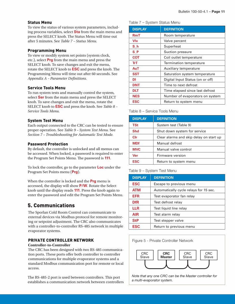
Status MenuTo view the status of various system parameters, includ-ing process variables, select Sta from the main menu and press the SELECT knob. The Status Menu will time out after 5 minutes. See Table 7 – Status Menu.
Programming MenuTo view or modify system set points (system clock, etc.), select Prg from the main menu and press the SELECT knob. To save changes and exit the menu, rotate the SELECT knob to ESC and press the knob. The Programming Menu will time out after 60 seconds. See Appendix A – Parameter Definitions.
Service Tools MenuTo run system tests and manually control the system, select Ser from the main menu and press the SELECT knob. To save changes and exit the menu, rotate the SELECT knob to ESC and press the knob. See Table 8 – Service Tools Menu.
System Test MenuEach output connected to the CRC can be tested to ensure proper operation. See Table 9 – System Test Menu. See Section 7 – Troubleshooting for Automatic Test Mode.
Password ProtectionBy default, the controller is unlocked and all menus can be accessed. When locked, a password is required to enter the Program Set Points Menu. The password is 111.
To lock the controller, go to the parameter Loc under the Program Set Points menu (Prg).
When the controller is locked and the Prg menu is accessed, the display will show P/W. Rotate the Select knob until the display reads 111. Press the knob again to enter the password and edit the Program Set Points Menu.
5. CommunicationsThe Sporlan Cold Room Control can communicate to external devices via Modbus protocol for remote monitor-ing or setpoint adjustment. The CRC also communicates with a controller-to-controller RS-485 network in multiple evaporator systems.
PRIVATE CONTROLLER NETWORKController-to-ControllerThe CRC has been designed with two RS-485 communica-tion ports. These ports offer both controller to controller communications for multiple evaporator systems and a standard Modbus communication port for remote or local access.
The RS-485-2 port is used between controllers. This port establishes a communication network between controllers
DISPLAY DEFINITION
RmT Room temperature
Vlv Valve percent
S_h Superheat
S_P Suction pressure
COT Coil outlet temperature
TrT Termination temperature
AuT Auxiliary temperature
SST Saturation system temperature
DI Digital Input Status (on or off)
DNT Time to next defrost
DLT Time elapsed since last defrost
NES Number of evaporators on system
ESC Return to system menu
Table 7 – System Status Menu
DISPLAY DEFINITION
TSt System test (Table 9)
Shd Shut down system for service
Clr Clear alarms and skip delay on start up
MDf Manual defrost
MVC Manual valve control
Ver Firmware version
ESC Return to system menu
Table 8 – Service Tools Menu
DISPLAY DEFINITION
ESC Escape to previous menu
ATM Automatically cycle relays for 15 sec.
EFR Test evaporator fan relay
DfR Test defrost relay
LLR Test liquid line relay
AlR Test alarm relay
StP Test stepper valve
ESC Return to previous menu
Table 9 – System Test Menu
Figure 5 - Private Controller Network
Note that any one CRC can be the Master controller for a multi-evaporator system.
CRCSlave
CRCSlave
CRCSlave
CRCMaster

Page 12 – Bulletin 100-50-4.1
Third Party Controllers: To avoid nuisance “network errors”, the use of third party controllers on the same RS-485 network with the Sporlan Cold Room Control is not recommended.
MODBUS NETWORKCRC Network-to-External DeviceRS-485-1 is used to connect a Modbus network that can be used to view system parameters, provide remote access and log system data from the CRC. Third party web serv-ers or equivalent devices are available for these extended features. It may also be networked into a system level con-troller such as a rack controller. Contact Parker Hannifin-Sporlan Division to review available products. RS-485-1 port does not need to be used unless the above features are needed. It should be noted that communication wir-ing must be daisy chained between all controllers on the RS-485-1 network. See CRC Modbus Map – Appendix D.
6. PID TuningNOTE: Only experienced professionals should access this feature. System stability and perfor-mance may be improved by adjusting PID settings.
It will be necessary to verify proper superheat control and EEV operation after the system is running. The Cold Room Control is factory programmed with default Proportional-Integral-Derivative (PID) settings that will provide effi-cient control. The PID values may be adjusted if superheat or EEV movement is not stable. If superheat is oscillating around setpoint at steady state conditions, reduce PID set-tings to half of the existing values. When PID adjustments are made, allow adequate time for the system to respond to changes. In general, when the superheat is oscillating to extremes, the Proportional and/or the Integral may be too high. If superheat is slow to react to a transient system change, then the Proportional and/or the Integral value may be too low.
NOTE: Not all refrigeration systems are designed alike. Use caution when tuning PID setpoints.
7. TroubleshootingAs with any refrigeration component troubleshooting, actual system conditions should be verified with a gauge set and calibrated temperature sensor (i.e verify actual superheat, subcooling and refrigerant condition). This system information is valuable in determining whether it is component related or system related.
For systems or applications that experience light loads, it is important that the evaporator and refrigerant lines are sized correctly. This will ensure proper oil return and will minimize the effects of oil logging in the evaporator. Refer to the evaporator manufacturer’s installation instructions.
on multiple evaporator systems. The communication wir-ing must be daisy chained between all RS-485-2 ports on each controller, per walk-in freezer or cooler, for proper system operation. See Figure 4. One button setup estab-lishes addresses of slaves.
ConnectionsWire Type: 22-24 AWG Universal Twisted PairMaximum Number of Network Nodes: 8Maximum Run Length: 40 ft (100 ft for public)
Recommended Network Configuration: Daisy Chain, a single continuous transmission line from one end to the other. Other configurations involving triple-lug connec-tions, such as star, are not recommended. See Figure 4.
Wiring: Proper communication wiring and routing is necessary to avoid nuisance errors or poor system perfor-mance. The following guidelines must be followed:• The correct wire type and shielding must be used for
communication lines.• The correct network wire configuration must be used.• Communication lines must run at least 6” away from
high power lines if they run parallel with each other.• Communication lines must run perpendicular to high
power lines if they cross each other.• Communication lines should not be installed near
high voltage or electromagnetic components.• Proper grounding must be used for both controller
and system.
Noise Reduction: Termination resistance is recom-mended to reduce reflections and noise on the data trans-mission lines. Place the resistance at the extreme ends of the cable with the resistance value matching the charac-teristic impedance of the transmission line (typically 120 ohms for twisted pair cables). Shielding prevents noise from EMI sources. If the cable is shielded, connect the shield to earth ground at one end only.
NOTE: Do not connect shield to RS-485 GND.
Keep RS-485 wiring away from high voltage AC lines to reduce noise and data errors on communication lines. RS-485 cable should be perpendicular to AC lines at any intersection.
System Grounding: The walk in freezer or cooler box must be grounded correctly per local electrical codes to ensure proper controller operation. This will minimize stray noise that could interrupt communication and affect system operation.
Controller Grounding: Connect an optional third con-ductor to RS-485-2 GND to prevent ground potentials from node to node. This conductor should be included in the shield of the twisted pair cable to prevent noise. NOTE: Do not connect RS-485 GND to earth ground.
Bulletin 100-50-4.1 – Page 13
COLD ROOM CONTROLTst – Test can be used as a diagnostic tool to check opera-tion of the controller outputs such as relays and the EEV. System must be off (not running) during this mode to avoid damage to the compressor. For more information see Appendix B – Troubleshooting Chart. The Test feature is located under the SERVICE menu. The CRC offers two test modes; Automatic and Manual. See Table 9 for test menu options.
ATM – Automatic test mode – enter SERVICE menu and scroll to ATM. Press SELECT button once to start the automatic procedure. The controller will cycle thru and test each output starting with EFR – Evaporator Fan Relay. The relay will be powered on for 15 seconds. At this time, operation can be verified. The relay will then cycle off for 2 seconds before moving to DFR – Defrost Relay. After this, the controller will test the LLR – Liquid Line Relay followed by the AlR- Alarm Relay. The final test is for StP – Stepper Motor (EEV) output. The valve must be connected to the controller to verify operation. The controller will overdrive the valve closed. At this time, a light buzzing should be heard around the EEV. When the automatic test is com-plete, it will then display ATM. To exit, scroll to ESC. If at any time the test needs to be cancelled, press the SELECT button to exit. Sixty seconds after the procedure completes, the system will time out and return to the default menu.
EFR – Manual Test Mode – enter SERVICE menu and scroll past ATM and enter EFR to manually test each relay. Do not press select button while ATM is displayed. This will enter automatic mode. For example, to test the Defrost Relay, scroll to EFR and press the SELECT button. At this time, the controller will use the standard 15 seconds on and 2 second off cycle. All relays and EEV can be checked in manual mode by scrolling to the menu display and pressing the SELECT button. To exit, scroll to ESC and press SELECT button.
SENSORS Failed sensors will trigger an alarm. An alarm code will show which sensor is miswired, disconnected, or faulty. (See Appendix B - Troubleshooting Chart) The alarm will persist until the problem is corrected.
Failed temperature sensors will generally read extremely low or infinite resistance when tested with an ohmmeter. Readings should be taken with the sensor disconnected from the Subcool Control. A missing or disconnected tem-perature sensor will read -60 on the controller.
Temperature sensor output can be checked by measuring the DC voltage across the sensor wire using the tables in Appendix C.
Since the liquid and room temperature sensors are identi-cal, no alarm will be triggered if the sensors are switched.
WARNING: Severe system damage may occur if these two sensor locations are interchanged.
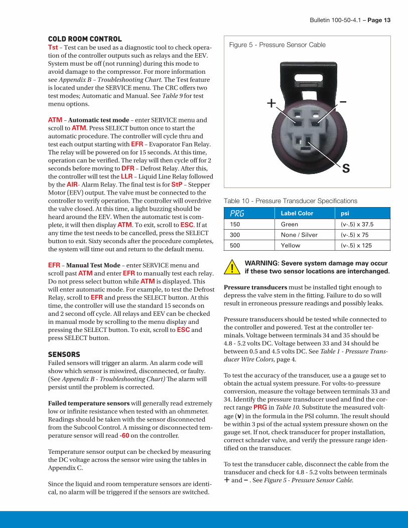
Pressure transducers must be installed tight enough to depress the valve stem in the fitting. Failure to do so will result in erroneous pressure readings and possibly leaks.
Pressure transducers should be tested while connected to the controller and powered. Test at the controller ter-minals. Voltage between terminals 34 and 35 should be 4.8 - 5.2 volts DC. Voltage between 33 and 34 should be between 0.5 and 4.5 volts DC. See Table 1 - Pressure Trans-ducer Wire Colors, page 4.
To test the accuracy of the transducer, use a a gauge set to obtain the actual system pressure. For volts-to-pressure conversion, measure the voltage between terminals 33 and 34. Identify the pressure transducer used and find the cor-rect range PRG in Table 10. Substitute the measured volt-age (v) in the formula in the PSI column. The result should be within 3 psi of the actual system pressure shown on the gauge set. If not, check transducer for proper installation, correct schrader valve, and verify the pressure range iden-tified on the transducer.
To test the transducer cable, disconnect the cable from the transducer and check for 4.8 - 5.2 volts between terminals + and – . See Figure 5 - Pressure Sensor Cable.
Figure 5 - Pressure Sensor Cable
S
+ –
Label Color psi
150 Green (v-.5) x 37.5
300 None / Silver (v-.5) x 75
500 Yellow (v-.5) x 125
Table 10 - Pressure Transducer Specifications

Page 14 – Bulletin 100-50-4.1
CONTROLLER REPLACEMENT1. Safely shut down refrigeration system.2. Record all system parameters and set points from the
controller.3. Remove power from the CRC.4. Carefully label and unplug all connections to the CRC.5. Remove controller from snap track.6. Referring to Section 1 of this manual, install replace-
ment CRC.7. If the replacement controller was a networked MAS-
TER, See Section 2 and information from Step 2 above to complete setup. Press SELECT knob on each Slave controller after the new Master board is set up and operating.
8. If the replacement controller was a networked SLAVE, press the SELECT knob on the new controller after it is installed and powered up.
COMMUNICATION ERROROn multi-evaporator setups, a communication error will activate the CoE alarm on the MASTER controller and the affected SLAVE. If this occurs, there will be no effect on the MASTER controller operation, and the SLAVE control-ler will continue to operate with the last known settings (including defrost).
Clearing the alarm on the MASTER will reset the alarm sta-tus and detach the faulty SLAVE from the network. Clear-ing the alarm on the SLAVE will reset the alarm status and the SLAVE will operate in stand-alone mode. To reattach the SLAVE controller to the CRC network, reestablish the network connection the MASTER and then press the select button on the SLAVE.
ALARMSAlarm codes are in Table 11 below. To reset alarms, go to Clear Alarms (Clr) under Service Tools (Ser). System test options are also located under the Service Tools menu (TSt). See Table 9 - System Test Menu, and Appendix B - Troubleshooting Chart.
DISPLAY DEFINITION
ShL Superheat Low1
ShH Superheat High
RmL Room Temperature Low2
RmH Room Temperature High2
SuL Suction Pressure Low3
SuH Suction Pressure High3
COL Coil Outlet Temperature Low4
COH Coil Outlet Temperature High4
TTL Termination Temperature Low5
TTH Termination Temperature High5
AxL Auxiliary Temperature Low
AxH Auxiliary Temperature High
CoE Communication Error Alarm
1. Low superheat action is determined by the CDP parameter.2. If RmT in the System Status Menu shows Err, the CRC will use
Coil Outlet Temp to maintain refrigeration.3. If S_P in the System Status Menu shows Err, the CRC will posi-
tion the EEV at the failsafe position. If the system is a multi-evaporator system and PbS is enabled, the Master will use an available pressure transducer on the CRC network to continue to operate.
4. If COT in the System Status Menu shows Err, the CRC will posi-tion the EEV at the failsafe position. Following defrost, the CRC will use the FMD parameter to determine fan delay.
5. If TrT in System Status Menu shows Err, the CRC will use the DFS parameter to end defrost.
Table 11 - Alarms
ELECTRICALSupply Voltage 20-26VAC 50/60Hz or 22-26.6VDC; Class II Input
Digital Inputs 0-5VDC Maximum Range Interface to dry contact or open collector
Analog Inputs (4) Temperature Sensors – 3K ohm (1) Pressure Transducer – 0.5 to 4.5VR (150 psig, 300 psig, or 500 psig)
Relay Outputs Heater/Fan – 240VAC/40A res (30A ind) Solenoid – 400VAC/3A res Alarm – 277VAC/6A res
Battery Life More than 10 years (during active operation)
Digital Display LED - Red, 16 segment, 3 digit
Indicators LED – Power (Green), Relay Active (Red), Communication (Green/Yellow)
User Interface Optical Encoder (SELECT knob)
Data Interface (2) RS485, Modbus
MECHANICALOperating Temperature -40°F to 158°F (-40°C to 70°C)
Humidity 0-95%RH (Non-Condensing)
Wiring Screw Terminals
8. System Specifications
Bulletin 100-50-4.1 – Page 15
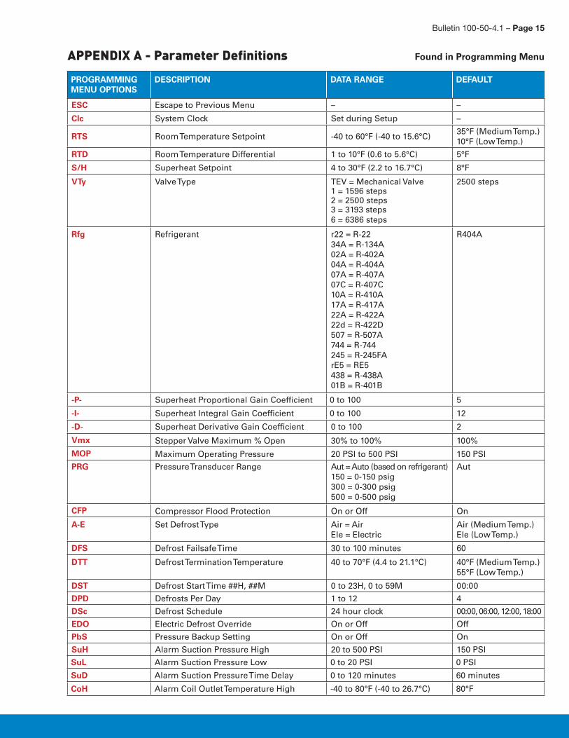
APPENDIX A - Parameter Definitions
PROGRAMMING MENU OPTIONS
DESCRIPTION DATA RANGE DEFAULT
ESC Escape to Previous Menu – –
Clc System Clock Set during Setup –
RTS Room Temperature Setpoint -40 to 60°F (-40 to 15.6°C)35°F (Medium Temp.)10°F (Low Temp.)
RTD Room Temperature Differential 1 to 10°F (0.6 to 5.6°C) 5°F
S/H Superheat Setpoint 4 to 30°F (2.2 to 16.7°C) 8°F
VTy Valve Type TEV = Mechanical Valve1 = 1596 steps2 = 2500 steps3 = 3193 steps6 = 6386 steps
2500 steps
Rfg Refrigerant r22 = R-2234A = R-134A02A = R-402A04A = R-404A07A = R-407A07C = R-407C10A = R-410A17A = R-417A22A = R-422A22d = R-422D507 = R-507A744 = R-744245 = R-245FArE5 = RE5438 = R-438A01B = R-401B
R404A
-P- Superheat Proportional Gain Coefficient 0 to 100 5
-I- Superheat Integral Gain Coefficient 0 to 100 12
-D- Superheat Derivative Gain Coefficient 0 to 100 2
Vmx Stepper Valve Maximum % Open 30% to 100% 100%
MOP Maximum Operating Pressure 20 PSI to 500 PSI 150 PSI
PRG Pressure Transducer Range Aut = Auto (based on refrigerant)150 = 0-150 psig300 = 0-300 psig500 = 0-500 psig
Aut
CFP Compressor Flood Protection On or Off On
A-E Set Defrost Type Air = AirEle = Electric
Air (Medium Temp.)Ele (Low Temp.)
DFS Defrost Failsafe Time 30 to 100 minutes 60
DTT Defrost Termination Temperature 40 to 70°F (4.4 to 21.1°C) 40°F (Medium Temp.) 55°F (Low Temp.)
DST Defrost Start Time ##H, ##M 0 to 23H, 0 to 59M 00:00
DPD Defrosts Per Day 1 to 12 4
DSc Defrost Schedule 24 hour clock 00:00, 06:00, 12:00, 18:00
EDO Electric Defrost Override On or Off Off
PbS Pressure Backup Setting On or Off On
SuH Alarm Suction Pressure High 20 to 500 PSI 150 PSI
SuL Alarm Suction Pressure Low 0 to 20 PSI 0 PSI
SuD Alarm Suction Pressure Time Delay 0 to 120 minutes 60 minutes
CoH Alarm Coil Outlet Temperature High -40 to 80°F (-40 to 26.7°C) 80°F
Found in Programming Menu

Page 16 – Bulletin 100-50-4.1
APPENDIX A - Parameter Definitions (continued)
PROGRAMMING MENU OPTIONS
DESCRIPTION DATA RANGE DEFAULT
CoL Alarm Coil Outlet Temperature Low -40 to 80°F (-40 to 26.7°C) -40°F
CoD Alarm Coil Outlet Temperature Time Delay 0 to 120 minutes 60 minutes
RmH Alarm Room Temperature High -40 to 80°F (-40 to 26.7°C) 50°F (Medium Temp.)30°F (Low Temp.)
RmL Alarm Room Temperature Low -40 to 80°F (-40 to 26.7°C) 30°F (Medium Temp.)-25°F (Low Temp.)
RmD Alarm Room Temperature Time Delay 0 to 120 minutes 60 minutes
TTH Alarm Defrost Termination Temperature High
-40 to 80°F (-40 to 26.7°C) 80°F
TTL Alarm Defrost Termination Temperature Low
-40 to 80°F (-40 to 26.7°C) -40°F
TTD Alarm Defrost Termination Temperature Time Delay
0 to 120 minutes 60 minutes
AxH Alarm Auxiliary Temperature High -40 to 120°F (-40 to 48.9°C) 120°F
AxL Alarm Auxiliary Temperature Low -40 to 120°F (-40 to 48.9°C) -40°F
Axd Alarm Auxiliary Temperature Time Delay 0 to 120 minutes 60 minutes
ShH Alarm Superheat High 20 to 50°F (11.1 to 27.8°C) 20°F
ShL Alarm Superheat Low 0 to 15°F (0 to 8.3°C) 0°F
ShD Alarm Superheat Time Delay 0 to 120 minutes 60 minutes
MCT Minimum Cooling Time 1 to 40 minutes 2 minutes
MFT Minimum Off Time 1 to 20 minutes 4 minutes
CDT Coil Drain Time 1 to 10 minutes 3 minutes
FDT Evaporator Fan Delay Temperature 10 to 32°F (-12.2 to 0°C) 28°F
FMD Maximum Fan Delay Time 0 to 10 minutes 5 minutes
F-C Set Units to Fahrenheit or Celsius FAH = FahrenheitCEL = Celsius
FAH
Loc Lock/Unlock Lck = LockUnl = Unlock
Unl
M/S Master / Slave Select MSt = MasterSlv = Slave
Slv
Adr Modbus Address 1 to 32 1
Bau Modbus Baud Rate 96 = 9,600 bps192 = 19,200 bps384 = 38,400 bps
9600 bps
Par Modbus Parity Mode Non = No ParityEvn = Even ParityOdd = Odd Parity
Even Parity
SAR Slave Address Reset No = Don’t ResetYes = Reset
No
L/M Low or Medium Temperature Selection Lt = Low Temp.Mt = Medium Temp.
Set during Setup
LOG Data Logging Span 1 to 7 days 1 day
ESC Escape to Previous Menu – –

Bulletin 100-50-4.1 – Page 17
APPENDIX B - Troubleshooting Chart
PROBLEM CHECK SOLUTION
Controller board not powering up – no LEDS illuminated
Supply voltage Correct supply voltage
Wiring Correct per instructions
Board powers up but display characters not recognizable
Possible defective board Replace board
Board indicates active alarm status
Cancel alarm by SELECT keystroke Correct cause of alarm, check sensorsSensor failure Fix or replace sensorWiring Correct per instructions
Erratic superheat Sensor location Relocate to horizontal, clean suction line at 4 or 8 o’clock
Pressure transducer location Top of line near temperature sensor
Temperature sensor and transducer wiring Ensure wire contact in connectorsEnsure wire contact in splicesEnsure no corrosion in connectorsCorrect per instructions
Valve wiring and function Refer to valve service instruction SD-243
High superheat Superheat setpoint Set correct setpointSensor location See aboveTemperature sensor and transducer wiring See aboveSystem refrigerant charge Correct chargeValve wiring and function Refer to valve service instruction SD-243CRC refrigerant selection Change to system refrigerant
Low superheat Superheat setpoint Set correct setpointSensor location See aboveTemperature sensor and transducer wiring See aboveSystem refrigerant charge Correct chargeCRC refrigerant selection Change to system refrigerantValve wiring and function Refer to valve service instruction SD-243
Fan relay inoperative Relay jumpers to board Correct wiring to jumper connectors
Fans always on Relay wiring Correct wiring to N.C. terminalsCorrect per instructions
Relay contacts Common to N.O. should have infinite resistance
Fan and defrost parameters CorrectRelay jumpers to board Correct wiring to jumper connectors
Fans always off Wiring Correct wiring to N.C. terminalsCorrect per instructions
Relay contacts Common to N.C. should have zeroresistance
Fan and defrost parameters CorrectRelay jumpers to board Correct wiring to jumper connectors
Heater relay inoperative Wiring Correct per instructionsCorrect wiring to N.O. terminals
Heater always on Relay contacts Common to N.O. should have infinite resistance
Heater always off Fan and defrost parameters CorrectRelay jumpers to board Correct wiring to jumper connectors
Relay wiring Correct wiring to N.C. terminalsCorrect per instructions
Relay contacts Common to N.O. should have infinite resistance
Fan and defrost parameters Correct
Liquid line solenoid inoperable Solenoid coil ReplaceSolenoid voltage Correct or replace coilSolenoid wiring Correct per instructions
Page 18 – Bulletin 100-50-4.1
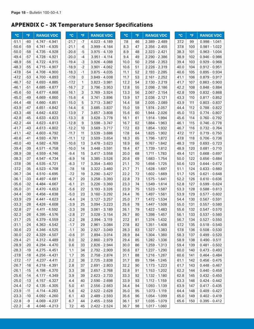
APPENDIX C - 3K Temperature Sensor Specifications
°C °F RANGE VDC
-51.1 -60 4.747 - 4.941-50.6 -59 4.741 - 4.935-50.0 -58 4.735 - 4.928-49.4 -57 4.728 - 4.921-48.9 -56 4.722 - 4.915-48.3 -55 4.715 - 4.907-47.8 -54 4.708 - 4.900-47.2 -53 4.700 - 4.893-46.7 -52 4.693 - 4.885-46.1 -51 4.685 - 4.877-45.6 -50 4.677 - 4.868-45.0 -49 4.669 - 4.860-44.4 -48 4.660 - 4.851-43.9 -47 4.651 - 4.842-43.3 -46 4.642 - 4.832-42.8 -45 4.633 - 4.823-42.2 -44 4.623 - 4.813-41.7 -43 4.613 - 4.802-41.1 -42 4.603 - 4.792-40.6 -41 4.593 - 4.781-40.0 -40 4.582 - 4.769-39.4 -39 4.571 - 4.758-38.9 -38 4.559 - 4.746-38.3 -37 4.547 - 4.734-37.8 -36 4.535 - 4.721-37.2 -35 4.523 - 4.708-36.7 -34 4.510 - 4.695-36.1 -33 4.497 - 4.681-35.6 -32 4.484 - 4.667-35.0 -31 4.470 - 4.653-34.4 -30 4.456 - 4.638-33.9 -29 4.441 - 4.623-33.3 -28 4.426 - 4.608-32.8 -27 4.411 - 4.592-32.2 -26 4.395 - 4.576-31.7 -25 4.379 - 4.559-31.1 -24 4.363 - 4.542-30.6 -23 4.346 - 4.525-30.0 -22 4.329 - 4.507-29.4 -21 4.312 - 4.489-28.9 -20 4.294 - 4.470-28.3 -19 4.275 - 4.451-27.8 -18 4.256 - 4.431-27.2 -17 4.237 - 4.411-26.7 -16 4.218 - 4.391-26.1 -15 4.198 - 4.370-25.6 -14 4.177 - 4.349-25.0 -13 4.157 - 4.327-24.4 -12 4.135 - 4.305-23.9 -11 4.114 - 4.283-23.3 -10 4.092 - 4.260-22.8 -9 4.069 - 4.237-22.2 -8 4.046 - 4.213
°C °F RANGE VDC
-21.7 -7 4.023 - 4.189-21.1 -6 3.999 - 4.164-20.6 -5 3.975 - 4.139-20.0 -4 3.951 - 4.114-19.4 -3 3.926 - 4.088-18.9 -2 3.901 - 4.062-18.3 -1 3.875 - 4.035-17.8 0 3.849 - 4.008-17.2 1 3.823 - 3.981-16.7 2 3.796 - 3.953-16.1 3 3.769 - 3.924-15.6 4 3.741 - 3.896-15.0 5 3.713 - 3.867-14.4 6 3.685 - 3.837-13.9 7 3.657 - 3.808-13.3 8 3.628 - 3.778-12.8 9 3.598 - 3.747-12.2 10 3.569 - 3.717-11.7 11 3.539 - 3.686-11.1 12 3.509 - 3.654-10.6 13 3.478 - 3.623-10.0 14 3.448 - 3.591-9.4 15 3.417 - 3.558-8.9 16 3.385 - 3.526-8.3 17 3.354 - 3.493-7.8 18 3.322 - 3.460-7.2 19 3.290 - 3.427-6.7 20 3.258 - 3.393-6.1 21 3.226 - 3.360-5.6 22 3.193 - 3.326-5.0 23 3.160 - 3.292-4.4 24 3.127 - 3.257-3.9 25 3.094 - 3.223-3.3 26 3.061 - 3.189-2.8 27 3.028 - 3.154-2.2 28 2.994 - 3.119-1.7 29 2.961 - 3.084-1.1 30 2.927 - 3.049-0.6 31 2.894 - 3.0140.0 32 2.860 - 2.9790.6 33 2.826 - 2.9441.1 34 2.792 - 2.9091.7 35 2.758 - 2.8742.2 36 2.725 - 2.8382.8 37 2.691 - 2.8033.3 38 2.657 - 2.7683.9 39 2.623 - 2.7334.4 40 2.590 - 2.6985.0 41 2.556 - 2.6635.6 42 2.522 - 2.6286.1 43 2.489 - 2.5936.7 44 2.455 - 2.5587.2 45 2.422 - 2.524
°C °F RANGE VDC
7.8 46 2.389 - 2.4898.3 47 2.356 - 2.4558.9 48 2.323 - 2.4219.4 49 2.290 - 2.38610.0 50 2.258 - 2.35310.6 51 2.226 - 2.31911.1 52 2.193 - 2.28511.7 53 2.161 - 2.25212.2 54 2.130 - 2.21912.8 55 2.098 - 2.18613.3 56 2.067 - 2.15413.9 57 2.036 - 2.12114.4 58 2.005 - 2.08915.0 59 1.974 - 2.05715.6 60 1.944 - 2.02616.1 61 1.914 - 1.99416.7 62 1.884 - 1.96317.2 63 1.854 - 1.93217.8 64 1.825 - 1.90218.3 65 1.796 - 1.87218.9 66 1.767 - 1.84219.4 67 1.739 - 1.81220.0 68 1.711 - 1.78320.6 69 1.683 - 1.75421.1 70 1.656 - 1.72521.7 71 1.628 - 1.69722.2 72 1.602 - 1.66922.8 73 1.575 - 1.64123.3 74 1.549 - 1.61423.9 75 1.523 - 1.58724.4 76 1.497 - 1.56125.0 77 1.472 - 1.53425.6 78 1.447 - 1.50826.1 79 1.422 - 1.48326.7 80 1.398 - 1.45727.2 81 1.374 - 1.43227.8 82 1.351 - 1.40828.3 83 1.327 - 1.38328.9 84 1.304 - 1.36029.4 85 1.282 - 1.33630.0 86 1.259 - 1.31330.6 87 1.237 - 1.29031.1 88 1.216 - 1.26731.7 89 1.194 - 1.24532.2 90 1.173 - 1.22332.8 91 1.153 - 1.20233.3 92 1.132 - 1.18033.9 93 1.112 - 1.15934.4 94 1.093 - 1.13935.0 95 1.073 - 1.11935.6 96 1.054 - 1.09936.1 97 1.035 - 1.07936.7 98 1.017 - 1.060
°C °F RANGE VDC
37.2 99 0.998 - 1.04137.8 100 0.981 - 1.02238.3 101 0.963 - 1.00438.9 102 0.946 - 0.98639.4 103 0.929 - 0.96840.0 104 0.912 - 0.95140.6 105 0.895 - 0.93441.1 106 0.879 - 0.91741.7 107 0.863 - 0.90042.2 108 0.848 - 0.88442.8 109 0.832 - 0.86843.3 110 0.817 - 0.85243.9 111 0.803 - 0.83744.4 112 0.788 - 0.82245.0 113 0.774 - 0.80745.6 114 0.760 - 0.79246.1 115 0.746 - 0.77846.7 116 0.732 - 0.76447.2 117 0.719 - 0.75047.8 118 0.706 - 0.73648.3 119 0.693 - 0.72348.9 120 0.681 - 0.71049.4 121 0.668 - 0.69750.0 122 0.656 - 0.68450.6 123 0.644 - 0.67251.1 124 0.633 - 0.66051.7 125 0.621 - 0.64852.2 126 0.610 - 0.63652.8 127 0.599 - 0.62453.3 128 0.588 - 0.61353.9 129 0.577 - 0.60254.4 130 0.567 - 0.59155.0 131 0.557 - 0.58055.6 132 0.547 - 0.57056.1 133 0.537 - 0.56056.7 134 0.527 - 0.55057.2 135 0.518 - 0.54057.8 136 0.508 - 0.53058.3 137 0.499 - 0.52058.9 138 0.490 - 0.51159.4 139 0.481 - 0.50260.0 140 0.473 - 0.49360.6 141 0.464 - 0.48461.1 142 0.456 - 0.47561.7 143 0.448 - 0.46762.2 144 0.440 - 0.45962.8 145 0.432 - 0.45063.3 146 0.424 - 0.44263.9 147 0.417 - 0.43564.4 148 0.409 - 0.42765.0 149 0.402 - 0.41965.6 150 0.395 - 0.412

Bulletin 100-50-4.1 – Page 19
APPENDIX D - CRC Modbus Map
MODBUSFUNCTION CODE
DATA MAP DATA DESCRIPTIONS DATA RANGE
Read Coils (0x01) 0 Evaporator Fan Relay Status 0 = De-energized1 = Energized
1 Defrost Relay Status 0 = De-energized1 = Energized
2 Liquid Line Solenoid Relay Status 0 = De-energized1 = Energized
3 Alarm Relay Status 0 = De-energized1 = Energized
Read HoldingRegister (0x03)
0 Clock Time Hour 0 to 231 Clock Time Minute 0 to 592 Room Temperature Set Point -40 to 60°F
(-40.0 to 15.5°C)3 Room Temperature Differential 1 to 10°F
(0.6 to 5.5°C)4 Superheat Setpoint 4 to 30°F
(2.2 to 16.6°C)
5 Valve Type 0 = TEV1 = 1596 steps2 = 2500 steps3 = 3193 steps6 = 6386 steps
6 Refrigerant Type 0 = R-221 = R-134A2 = R-402A3 = R-404A4 = R-407A5 = R-407C6 = R-410A7 = R-417A8 = R-422A9 = R-422D10 = R-507A11 = R-74412 = R-245FA13 = R-E514 = R-438A15 = R-401B
7 Superheat Proportional Gain Coefficient 0 to 1008 Superheat Integral Gain Coefficient 0 to 1009 Superheat Derivative Gain Coefficient 0 to 10010 Stepper Valve Maximum % Open 30% to 100%11 Maximum Operating Pressure 20 PSI to 500 PSI
12 Pressure Range 0 = Auto (Based on refrigerant)1 = 0 to 150 PSI2 = 0 to 300 PSI3 = 0 to 500 PSI
13 Compressor Flood Protection 0 = Off1 = On
14 Defrost Type 0 = Air1 = Electric
15 Reserved16 Reserved17 Defrost Failsafe Time 30 to 100 minutes18 Defrost Termination Temperature 40 to 70°F
(4.4 to 21.1°C)

Page 20 – Bulletin 100-50-4.1
APPENDIX D - CRC Modbus Map (continued)
MODBUSFUNCTION CODE
DATA MAP DATA DESCRIPTIONS DATA RANGE
Read HoldingRegister (0x03)
19 Defrost Start Time Hour 0 to 2320 Defrost Start Time Minute 0 to 5921 Defrosts Per Day 2 to 1222 Defrost Time 1 Hour 0 to 2323 Defrost Time 1 Minute 0 to 5924 Defrost Time 2 Hour 0 to 2325 Defrost Time 2 Minute 0 to 5926 Defrost Time 3 Hour 0 to 2327 Defrost Time 3 Minute 0 to 5928 Defrost Time 4 Hour 0 to 2329 Defrost Time 4 Minute 0 to 5930 Defrost Time 5 Hour 0 to 2331 Defrost Time 5 Minute 0 to 5932 Defrost Time 6 Hour 0 to 2333 Defrost Time 6 Minute 0 to 5934 Defrost Time 7 Hour 0 to 2335 Defrost Time 7 Minute 0 to 5936 Defrost Time 8 Hour 0 to 2337 Defrost Time 8 Minute 0 to 5938 Defrost Time 9 Hour 0 to 2339 Defrost Time 9 Minute 0 to 5940 Defrost Time 10 Hour 0 to 2341 Defrost Time 10 Minute 0 to 5942 Defrost Time 11 Hour 0 to 2343 Defrost Time 11 Minute 0 to 5944 Defrost Time 12 Hour 0 to 2345 Defrost Time 12 Minute 0 to 5946 Pressure Backup Setting 0 = Off
1 = On47 Alarm Suction Pressure High 20 to 500 PSI48 Alarm Suction Pressure Low 0 to 20 PSI49 Alarm Suction Pressure Time Delay 0 to 120 minutes50 Alarm Coil Outlet Temperature High -40 to 80°F
(-40.0 to 26.6°C)
51 Alarm Coil Outlet Temperature Low -40 to 80°F(-40.0 to 26.6°C)
52 Alarm Coil Outlet Temperature Time Delay 0 to 120 minutes53 Alarm Room Temperature High -40 to 80°F
(-40.0 to 26.6°C)
54 Alarm Room Temperature Low -40 to 80°F (-40.0 to 26.6°C)
55 Alarm Room Temperature Time Delay 0 to 120 minutes56 Alarm Defrost Termination Temperature High -40 to 80°F
(-40.0 to 26.6°C)
57 Alarm Defrost Termination Temperature Low -40 to 80°F (-40.0 to 26.6°C)
58 Alarm Defrost Termination Temperature Time Delay 0 to 120 minutes59 Alarm Auxiliary Temperature High -40 to 120°F
(-40.0 to 48.9°C)

Bulletin 100-50-4.1 – Page 21
MODBUSFUNCTION CODE
DATA MAP DATA DESCRIPTIONS DATA RANGE
Read HoldingRegister (0x03)
60 Alarm Auxiliary Temperature Low -40 to 120°F (-40.0 to 48.9°C)
61 Alarm Auxiliary Temperature Time Delay 0 to 120 minutes62 Alarm Superheat High 20 to 50°F
(11.1 to 27.7°C)
63 Alarm Superheat Low 0 to 15°F (0.0 to 8.3°C)
64 Alarm Superheat Time Delay 0 to 120 minutes65 Minimum Cooling Time 1 to 40 minutes
66 Minimum Off Time 1 to 20 minutes
67 Coil Drain Time 1 to 10 minutes68 Evaporator Fan Delay Temperature 10 to 32°F
(-12.2 to 0.0°C)69 Maximum Fan Delay Time 0 to 10 minutes
70 Temperature Units 0 = Fahrenheit1 = Celsius
71 Lock/Unlock 0 = Unlock1 = Lock
72 Master/Slave Select 0 = Slave1 = Master
73 Modbus Address 1 to 3274 Modbus Baud Rate 0 = 9,600 bps
1 = 19,200 bps2 = 38,400 bps
75 Modbus Parity Mode 0 = No Parity1 = Even Parity2 = Odd Parity
76 Slave Address Reset 0 = Don’t Reset1 = Reset
77 Low or Medium Temperature Selection 0 = Medium1 = Low
78 Data Logging Span 1 to 779 Electric Defrost Override 0 = Off
1 = OnRead InputRegisters (0x04)
0 Firmware Version 0 to 65,5351 Room Temperature -40 to 125°F
(-40.0 to 51.6°C)2 Valve % Open 0 to 100.0% Open3 Superheat 0 to 165°F
(0.0 to 91.6°C)4 Suction Pressure 0 to 500 PSI
Maximum Range5 Coil Outlet Temperature -40 to 125°F
(-40.0 to 51.6°C)6 Defrost Termination Temperature -40 to 125°F
(-40.0 to 51.6°C)7 Auxiliary Temperature -40 to 125°F
(-40.0 to 51.6°C)8 Saturation Temperature -40 to 125°F
(-40.0 to 51.6°C)9 Digital Input Status 0 = Off
1 = On10 Time to Next Defrost Hour 0 to 12
APPENDIX D - CRC Modbus Map (continued)

Page 22 – Bulletin 100-50-4.1
APPENDIX D - CRC Modbus Map (continued)
MODBUSFUNCTION CODE
DATA MAP DATA DESCRIPTIONS DATA RANGE
Read InputRegisters (0x04)
11 Time to Next Defrost Minute 0 to 5912 Time Since Last Defrost Hour 0 to 1213 Time Since Last Defrost Minute 0 to 5914 Number of Evaporators 1 to 815 Operating Mode Mode Value
Delay on Startup 0x00Off 0x01Cooling 0x02Defrost 0x03Drain 0x04Fan Delay 0x05Test 0x06Shutdown 0x07Pumpdown 0x08
Electric Defrost Override 0x09
16 Alarm Indicator Flags Alarm Bit Position
SuctionPressure High 0
Suction Pressure Low 1
Coil Outlet Temperature High 2
Coil Outlet Temperature Low 3
Room Temperature High 4
Room Temperature Low 5
Defrost Termination Temperature High 6
Defrost Termination Temperature Low 7
Auxiliary Temperature High 8
Auxiliary Temperature Low 9
Superheat High 10Superheat Low 11Controller Network Communications 12
Defrost 13Reserved 14-15
Write SingleRegister (0x06)
The max number of registers written at a time is 1.The limits are listed under ‘Read Holding Register.’

Bulletin 100-50-4.1 – Page 23
APPENDIX E - CRC Wiring Diagram
Fans
Load
LiquidLine Valve
Heaters
Evaporator Outlet Temp.
Suction PressureTransducer
Defrost Termination Temp.
Room Temp.
Auxiliary Temp.
L2L1
L1L1
L2L2
GreenBlack
24 VAC
RS-485-1GRD
-B+A
+5V+12V
Line
L1L2
RS-485-2
EEV
Not Used
-B+A
Alarm
COM
GRD
Black White
Red Green
Digital Input
SELECT Knob
NC
NO
COM
NC
NO
COM
White
APPENDIX F - Accessories
DESCRIPTION ITEM NUMBER NOTES
CRC Controller Board 953260
Parker Sporlan Temperature Probe 3K SURFACE/AIR SENSOR - Brass 952551 Includes 2 meter cable
Parker Sporlan Pressure Transducer PSPT0500SVSP-S PSPT0300SVSP-S PSPT0150SVSP-S
952576952574952572
0-500 psis transducer (R-744)0-300 psis transducer (R-410A)0-150 psis transducer (all other refrigerants)
Transducer Cables PSPT000000CP50 PSPT000000CP20
953100953192
5 meter cable2 meter cable
Electronic Expansion Valve Various Various See Bulletin 100-20 or contact Sporlan for sizing.
Liquid Line Valve Various Various Contact Sporlan for sizing.
Troubleshooting Accessories SMA-12 953276 Handheld digital instrument for testing EEV performance

Page 24 – Bulletin 100-50-4.1
APPENDIX G - System Schematic
Th
is s
chem
atic
is fo
r co
mp
on
ent
loca
tio
n o
nly
, no
t a
typ
ical
pip
ing
rec
om
men
dat
ion
.S
chem
atic
no
t to
sca
le.
Insu
lati
on
no
t sh
own
.
Dry
Co
nta
cts
Eva
p. O
utl
et Te
mp
.
Ro
om
Tem
p.
Wh
ite
Gre
enB
lack
Bla
ck
24V
AC
/DC
RS-485
Wh
ite
Gre
enR
ed
Gro
un
d
A+ B-
Pre
ssu
reTr
ansd
uce
r
Def
rost
Term
inat
ion
Tem
p.
L1
L2
Liq
uid
Lin
e S
ole
no
id V
alve
EE
V
Co
ld R
oo
m C
on
tro
l (C
RC
)
10”-
14”
Ele
ctri
cD
efro
stO
verr
ide
Rel
ayP
um
pd
own
Rel
ay
RS-485
Gro
un
d
A+ B-
Dry
Co
nta
cts
/ A
uxi
liary
Tem
p.
Eva
po
rato
r
Su
ctio
n O
utl
etTe
mp
. Sen
sor
min
imiz
e1”
- 2”
idea
l
Ala
rm
Hea
ter
Fan
s
Val
ve

Bulletin 100-50-4.1 – Page 25
APPENDIX H - CRC Board Indicator Lights
Fan RelayHeater Relay
Alarm Relay
Power
CommunicationRS-485-1 Transmit Receive
Liquid Line Solenoid
CommunicationRS-485-2 Transmit Receive

Page 26 – Bulletin 100-50-4.1
APPENDIX I - Maintenance Log Sheet
PARAMETER DATE SET PT OPERATOR NAME


Bulletin 100-50-4.1 / 32013© 2013 Parker Hannifin Corporation
Parker Hannifin CorporationSporlan Division206 Lange Drive • Washington, MO 63090 USAphone 636 239 1111fax 636 239 9130www.sporlan.com


