Jack Motion Capture Communication Protocol
1
Jack Motion Capture Communication Protocol
Jack Motion Capture Communication Protocol
2
Copyright
Copyright Notice and Terms of Use
Copyright (c) 2013 Siemens Product Lifecycle Management Software Inc. All rights
reserved. This documentation is licensed to the licensee of the Siemens PLM Software product ("the Licensee")
pursuant to the terms and conditions set forth below and in the applicable Siemens PLM Software license
agreement. The documentation at all times remains the property of Siemens PLM Software. The
information contained in this documentation is considered confidential to Siemens PLM Software and shall
not be disclosed to any third party except as expressly authorized by Siemens PLM Software.
Disclaimer of Warranties and Limitations on Liability SIEMENS PLM SOFTWARE MAKES NO WARRANTY, EITHER EXPRESS OR IMPLIED,
INCLUDING BUT NOT LIMITED TO ANY IMPLIED WARRANTIES OF MERCHANTABILITY OR
FITNESS FOR A PARTICULAR PURPOSE, REGARDING THIS DOCUMENTATION. SIEMENS
PLM SOFTWARE MAKES THIS DOCUMENTATION AVAILABLE TO LICENSEE SOLELY ON AN
"AS-IS" BASIS.
IN NO EVENT SHALL SIEMENS PLM SOFTWARE BE LIABLE FOR ANY DAMAGES TO
LICENSEE OR ANY OTHER PARTY WHETHER ARISING OUT OF CONTRACT OR FROM TORT
INCLUDING, BUT NOT LIMITED TO, LOSS OF DATA, PROFITS OR BUSINESS, COSTS OF
COVER OR ANY OTHER SPECIAL, INCIDENTAL, EXEMPLARY OR CONSEQUENTIAL
DAMAGES, EVEN IF SIEMENS PLM SOFTWARE HAS BEEN ADVISED OF THE POSSIBILITY OF
SUCH LOSS OR DAMAGES. SIEMENS PLM SOFTWARE 'S CUMULATIVE LIABILITY SHALL
NOT EXCEED THE LICENSE FEE PAID FOR USE OF THIS DOCUMENTATION AND A SINGLE-
USER LICENSE OF THE SOFTWARE PROGRAM(S) REFERENCED IN THE DOCUMENTATION.
THIS DOCUMENTATION AND THE SOFTWARE PROGRAM(S) REFERENCED IN THE
DOCUMENTATION ARE INTENDED TO BE USED ONLY BY TRAINED PROFESSIONALS AND
ARE NOT TO BE SUBSTITUTED FOR PROFESSIONAL JUDGMENT. LICENSEE IS SOLELY
RESPONSIBLE FOR ANY RESULTS OBTAINED FROM USING THE SOFTWARE INCLUDING
THE ADEQUACY OF INDEPENDENT TESTING OF RELIABILITY AND ACCURACY OF ANY
ITEM DESIGNED USING THE SOFTWARE. LICENSEE SHALL PROTECT, INDEMNIFY, AND
HOLD SIEMENS PLM SOFTWARE HARMLESS FROM ANY LOSS, COST, DAMAGES OR
EXPENSE ARISING FROM ANY CLAIM THAT IS IN ANY WAY ASSOCIATED WITH THIS
DOCUMENTATION OR THE SOFTWARE PROGRAM(S) REFERENCED IN THE
DOCUMENTATION.
Restrictions on Government Use The documentation is provided with RESTRICTED RIGHTS and use, duplication, or disclosure by the
U.S. Government is subject to restrictions set forth in FAR 52.227-19 (Commercial Computer Software -
Restricted Rights) and DFAR 252.227-7013(c)(1)(ii) (Rights in Technical Data and Computer Software),
as applicable. Manufacturer is Siemens Product Lifecycle Management Software Inc., 10824 Hope Street
Cypress, California USA 90630
Trademarks All Siemens PLM Software trademarks used in the documentation are protected by the U.S. - International
trademark rights of Siemens Product Lifecycle Management Software Inc. The unauthorized use of any
Siemens PLM Software trademark is strictly forbidden. All other trademarks or registered trademarks
belong to their respective holders.
Jack Motion Capture Communication Protocol
3
Table of Contents
Copyright ......................................................................................................................................... 2
Introduction....................................................................................................................................... 4
Marker Data ................................................................................................................................... 5
Body Data ...................................................................................................................................... 5
Glove Data ..................................................................................................................................... 6
Server/Client Configurations ............................................................................................................... 7
Sending marker and body data to Jack ................................................................................................. 8
Sending glove data to Jack .................................................................................................................. 9
Message formats .............................................................................................................................. 10
Integral Type Sizes ........................................................................................................................ 10
Message Part Encoding ................................................................................................................. 10
Message Structures and Encodings ................................................................................................ 12
Help ............................................................................................................................................... 19
Jack Motion Capture Communication Protocol
4
Introduction
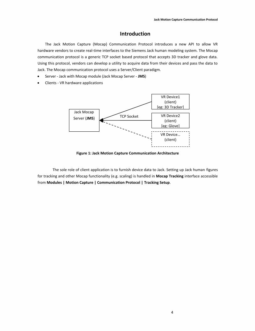
The Jack Motion Capture (Mocap) Communication Protocol introduces a new API to allow VR
hardware vendors to create real-time interfaces to the Siemens Jack human modeling system. The Mocap
communication protocol is a generic TCP socket based protocol that accepts 3D tracker and glove data.
Using this protocol, vendors can develop a utility to acquire data from their devices and pass the data to
Jack. The Mocap communication protocol uses a Server/Client paradigm.
Server - Jack with Mocap module (Jack Mocap Server - JMS)
Clients - VR hardware applications
Figure 1: Jack Motion Capture Communication Architecture
The sole role of client application is to furnish device data to Jack. Setting up Jack human figures
for tracking and other Mocap functionality (e.g. scaling) is handled in Mocap Tracking interface accessible
from Modules | Motion Capture | Communication Protocol | Tracking Setup.
TCP Socket Jack Mocap
Server (JMS)
VR Device1 (client)
[eg: 3D Tracker]
VR Device2 (client)
[eg: Glove]
VR Device… (client)
Jack Motion Capture Communication Protocol
5
Data Types
JMS handles three types VR device data:
1. Marker data (3DOF position)
2. Body data (6DOF position and orientation)
3. Glove data (24 joint angles)
Marker Data
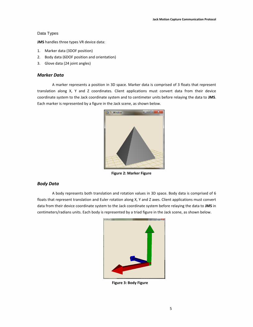
A marker represents a position in 3D space. Marker data is comprised of 3 floats that represent
translation along X, Y and Z coordinates. Client applications must convert data from their device
coordinate system to the Jack coordinate system and to centimeter units before relaying the data to JMS.
Each marker is represented by a figure in the Jack scene, as shown below.
Figure 2: Marker Figure
Body Data
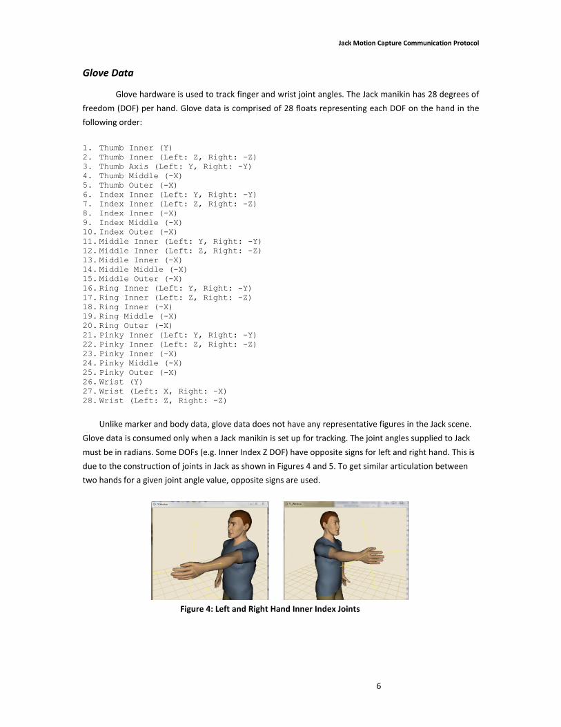
A body represents both translation and rotation values in 3D space. Body data is comprised of 6
floats that represent translation and Euler rotation along X, Y and Z axes. Client applications must convert
data from their device coordinate system to the Jack coordinate system before relaying the data to JMS in
centimeters/radians units. Each body is represented by a triad figure in the Jack scene, as shown below.
Figure 3: Body Figure
Jack Motion Capture Communication Protocol
6
Glove Data
Glove hardware is used to track finger and wrist joint angles. The Jack manikin has 28 degrees of
freedom (DOF) per hand. Glove data is comprised of 28 floats representing each DOF on the hand in the
following order:
1. Thumb Inner (Y) 2. Thumb Inner (Left: Z, Right: -Z) 3. Thumb Axis (Left: Y, Right: -Y) 4. Thumb Middle (-X) 5. Thumb Outer (-X) 6. Index Inner (Left: Y, Right: -Y) 7. Index Inner (Left: Z, Right: -Z) 8. Index Inner (-X) 9. Index Middle (-X) 10. Index Outer (-X) 11. Middle Inner (Left: Y, Right: -Y) 12. Middle Inner (Left: Z, Right: -Z) 13. Middle Inner (-X) 14. Middle Middle (-X) 15. Middle Outer (-X) 16. Ring Inner (Left: Y, Right: -Y) 17. Ring Inner (Left: Z, Right: -Z) 18. Ring Inner (-X) 19. Ring Middle (-X) 20. Ring Outer (-X) 21. Pinky Inner (Left: Y, Right: -Y) 22. Pinky Inner (Left: Z, Right: -Z) 23. Pinky Inner (-X) 24. Pinky Middle (-X) 25. Pinky Outer (-X) 26. Wrist (Y) 27. Wrist (Left: X, Right: -X) 28. Wrist (Left: Z, Right: -Z)
Unlike marker and body data, glove data does not have any representative figures in the Jack scene.
Glove data is consumed only when a Jack manikin is set up for tracking. The joint angles supplied to Jack
must be in radians. Some DOFs (e.g. Inner Index Z DOF) have opposite signs for left and right hand. This is
due to the construction of joints in Jack as shown in Figures 4 and 5. To get similar articulation between
two hands for a given joint angle value, opposite signs are used.
Figure 4: Left and Right Hand Inner Index Joints
Jack Motion Capture Communication Protocol
7
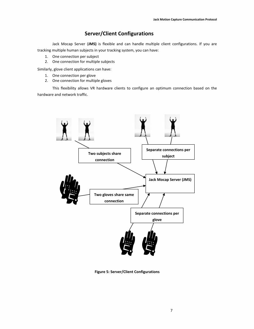
Server/Client Configurations
Jack Mocap Server (JMS) is flexible and can handle multiple client configurations. If you are
tracking multiple human subjects in your tracking system, you can have:
1. One connection per subject 2. One connection for multiple subjects
Similarly, glove client applications can have:
1. One connection per glove 2. One connection for multiple gloves
This flexibility allows VR hardware clients to configure an optimum connection based on the
hardware and network traffic.
Figure 5: Server/Client Configurations
Jack Mocap Server (JMS)
Two subjects share
connection
Two gloves share same
connection
Separate connections per
glove
Separate connections per
subject

Jack Motion Capture Communication Protocol
8
Sending marker and body data to Jack
The table below describes the process for sending marker and body data to Jack. The format for
sending various messages to Jack is described in the message formats section.
Step Jack (with Mocap module) VR device client application
1 Start JMS from Modules | Motion Capture |
Communication Protocol | Server Setup
2 Start client app and connect to JMS.
3 Register marker and body names with JMS.
4 A representative figure for each registered marker and body is created. An ORIGIN figure is also created. Figures are created only if they do not exist in the Jack scene. Duplicate marker or body names are made unique by adding a numerical suffix (marker, marker0, marker1..). ORIGIN figure determines the offset for all marker and body data.
5 Send marker and body locations to JMS.
6 Marker and body figure locations in Jack scene are updated based on the latest frame data relative to the location of the ORIGIN figure.
… Repeat 5...
… Repeat 6…
… ...
… …
7 Disconnect from JMS.
8 Marker and body figure locations stops updating.
Table 1: Sending marker and body data to Jack
Jack Motion Capture Communication Protocol
9
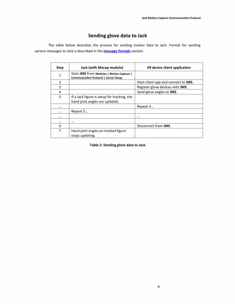
Sending glove data to Jack
The table below describes the process for sending marker data to Jack. Format for sending
various messages to Jack is described in the message formats section.
Step Jack (with Mocap module) VR device client application
1 Start JMS from Modules | Motion Capture |
Communication Protocol | Server Setup
2 Start client app and connect to JMS.
3 Register glove devices with JMS.
4 Send glove angles to JMS.
5 If a Jack figure is setup for tracking, the hand joint angles are updated.
… Repeat 4...
… Repeat 5…
… ...
… …
6 Disconnect from JMS.
7 Hand joint angles on tracked figure stops updating.
Table 2: Sending glove data to Jack
Jack Motion Capture Communication Protocol
10
Message formats
Each message packet on the network shall be a fixed size of 4096 bytes, network byte ordered
buffer. Jack Mocap Server (JMS) can handle the following five message types:
1. Registration Message (0) 2. Data Message (1) 3. Disconnect Message (2) 4. Glove Registration Message (3) 5. Glove Data Message (4)
The bold numbers in parenthesis following each message type above is the actual integer value
that should be encoded for that message type. The first two messages (Registration and Data) should be
used to communicate marker and body data. The Glove (Registration and Data) messages must be used to
communicate glove data. The Disconnect message should be used to disconnect from JMS.
Messages sent to the JMS should use the following encoding standards. First the encoding for
each message part is shown; this is followed with a description of the message encodings.
Integral Type Sizes
byte 8 bits
integer 4 bytes (network byte order encoded)
char 1 byte
float 4 bytes (network byte order encoded)
Message Part Encoding
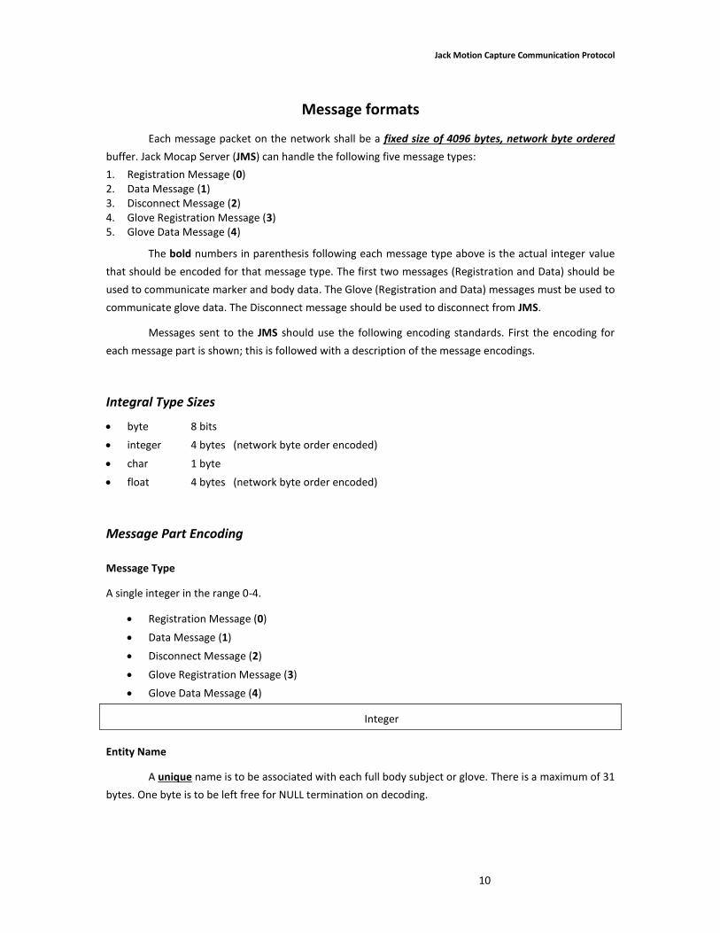
Message Type
A single integer in the range 0-4.
Registration Message (0)
Data Message (1)
Disconnect Message (2)
Glove Registration Message (3)
Glove Data Message (4)
Integer
Entity Name
A unique name is to be associated with each full body subject or glove. There is a maximum of 31
bytes. One byte is to be left free for NULL termination on decoding.
Jack Motion Capture Communication Protocol
11
char[32]
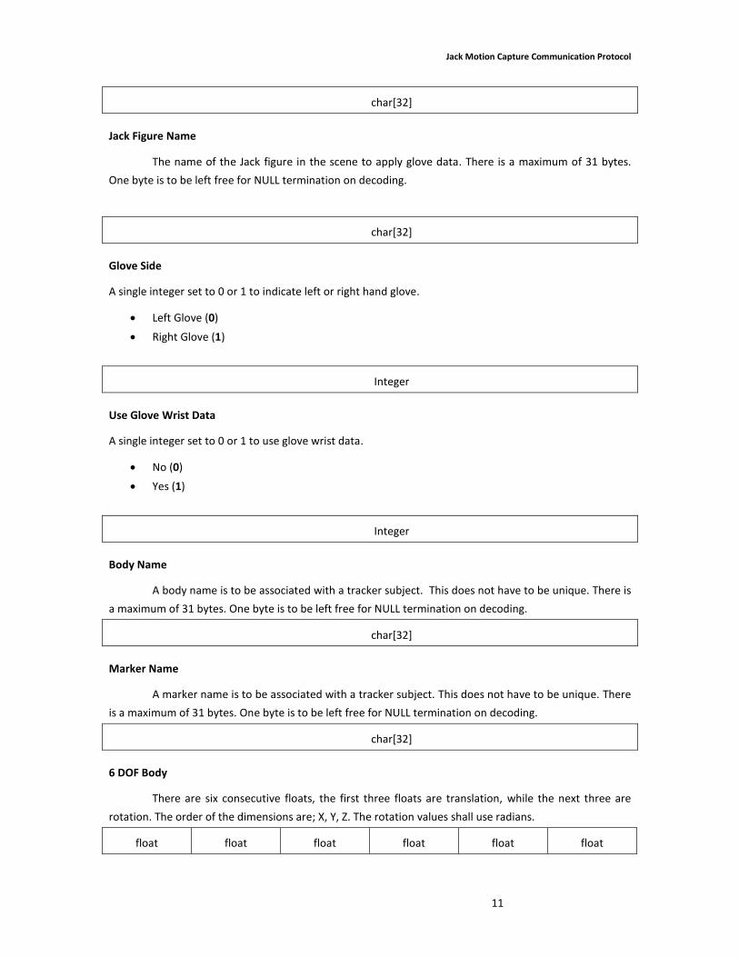
Jack Figure Name
The name of the Jack figure in the scene to apply glove data. There is a maximum of 31 bytes.
One byte is to be left free for NULL termination on decoding.
char[32]
Glove Side
A single integer set to 0 or 1 to indicate left or right hand glove.
Left Glove (0)
Right Glove (1)
Integer
Use Glove Wrist Data
A single integer set to 0 or 1 to use glove wrist data.
No (0)
Yes (1)
Integer
Body Name
A body name is to be associated with a tracker subject. This does not have to be unique. There is
a maximum of 31 bytes. One byte is to be left free for NULL termination on decoding.
char[32]
Marker Name
A marker name is to be associated with a tracker subject. This does not have to be unique. There
is a maximum of 31 bytes. One byte is to be left free for NULL termination on decoding.
char[32]
6 DOF Body
There are six consecutive floats, the first three floats are translation, while the next three are
rotation. The order of the dimensions are; X, Y, Z. The rotation values shall use radians.
float float float float float float
Jack Motion Capture Communication Protocol
12
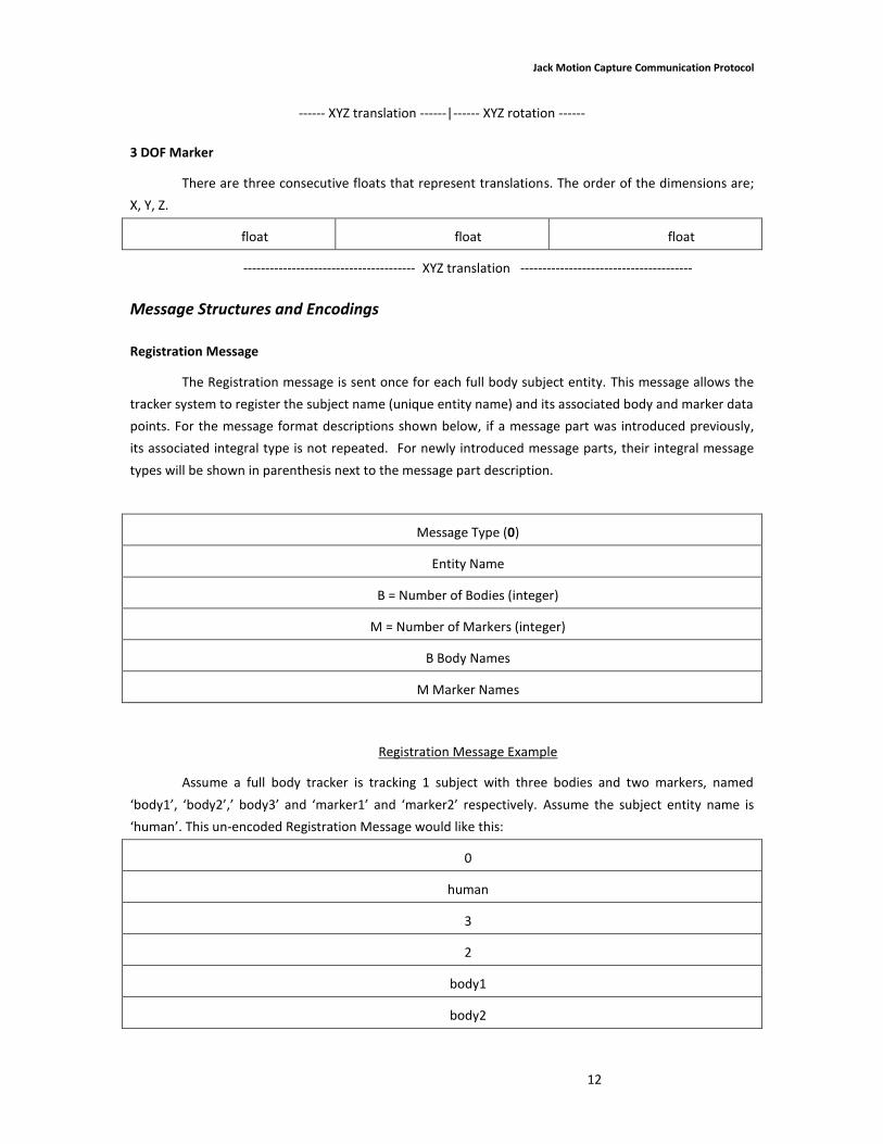
------ XYZ translation ------|------ XYZ rotation ------
3 DOF Marker
There are three consecutive floats that represent translations. The order of the dimensions are;
X, Y, Z.
float float float
--------------------------------------- XYZ translation ---------------------------------------
Message Structures and Encodings
Registration Message
The Registration message is sent once for each full body subject entity. This message allows the
tracker system to register the subject name (unique entity name) and its associated body and marker data
points. For the message format descriptions shown below, if a message part was introduced previously,
its associated integral type is not repeated. For newly introduced message parts, their integral message
types will be shown in parenthesis next to the message part description.
Message Type (0)
Entity Name
B = Number of Bodies (integer)
M = Number of Markers (integer)
B Body Names
M Marker Names
Registration Message Example
Assume a full body tracker is tracking 1 subject with three bodies and two markers, named
‘body1’, ‘body2’,’ body3’ and ‘marker1’ and ‘marker2’ respectively. Assume the subject entity name is
‘human’. This un-encoded Registration Message would like this:
0
human
3
2
body1
body2
Jack Motion Capture Communication Protocol
13
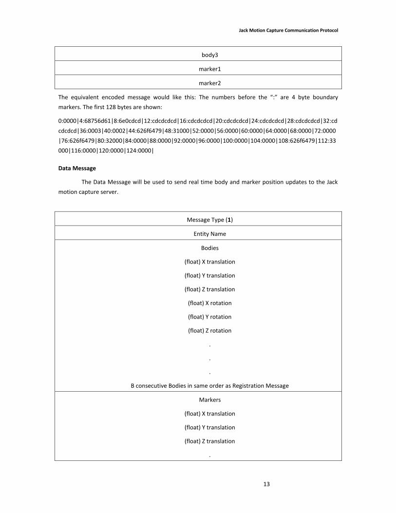
body3
marker1
marker2
The equivalent encoded message would like this: The numbers before the “:” are 4 byte boundary
markers. The first 128 bytes are shown:
0:0000|4:68756d61|8:6e0cdcd|12:cdcdcdcd|16:cdcdcdcd|20:cdcdcdcd|24:cdcdcdcd|28:cdcdcdcd|32:cd
cdcdcd|36:0003|40:0002|44:626f6479|48:31000|52:0000|56:0000|60:0000|64:0000|68:0000|72:0000
|76:626f6479|80:32000|84:0000|88:0000|92:0000|96:0000|100:0000|104:0000|108:626f6479|112:33
000|116:0000|120:0000|124:0000|
Data Message
The Data Message will be used to send real time body and marker position updates to the Jack
motion capture server.
Message Type (1)
Entity Name
Bodies
(float) X translation
(float) Y translation
(float) Z translation
(float) X rotation
(float) Y rotation
(float) Z rotation
.
.
.
B consecutive Bodies in same order as Registration Message
Markers
(float) X translation
(float) Y translation
(float) Z translation
.

Jack Motion Capture Communication Protocol
14
.
.
M consecutive Markers in same order as Registration Message
Data Message Example
Continuing with our same example, given with the Registration message assume the following
body and marker conditions are being sent:
Body1 = (10.0, 100.0, 20.0) translation
(0.45, 0.75, 0.25) rotation
Body2 = (11.0, 101.0, 21.0) translation
(0.46, 0.76, 0.26) rotation
Body3 = (12.0, 102.0, 22.0) translation
(0.47, 0.77, 0.27) rotation
Marker1 = (13.0, 103.0, 23.0) translation
Marker2 = (14.0, 104.0, 24.0) translation

Jack Motion Capture Communication Protocol
15
The un-encoded Data Message for this example would look like this:
1
human
10.0
100.0
20.0
0.45
0.75
0.25
11.0
101.0
21.0
0.46
0.76
0.26
12.0
102.0
22.0
0.47
0.77
0.27
13.0
103.0
23.0
14.0
104.0
24.0
Jack Motion Capture Communication Protocol
16
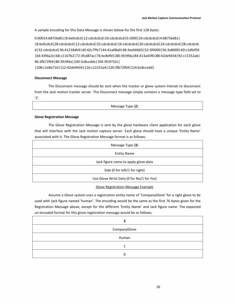
A sample encoding for this Data Message is shown below for the first 128 bytes:
0:00014:68756d61|8:6e0cdcd|12:cdcdcdcd|16:cdcdcdcd|0:1000|20:cdcdcdcd|4:68756d61|
|8:6e0cdcd|28:cdcdcdcd|12:cdcdcdcd|32:cdcdcdcd|16:cdcdcdcd|20:cdcdcdcd|24:cdcdcdcd|28:cdcdcdc
d|32:cdcdcdcd|36:41218db9|40:42c7ffe7|44:41a08a0|48:3ee66665|52:3f4000|56:3e8000|60:c1dfef93
|64:43fda2e|68:c1167b2|72:3fcd87ac|76:bc8efb5|80:3fc9fda|84:413a43f6|88:42de9434|92:c11552a6|
96:3fb72fb9|80:3fc9fda|100:3c8ccdeb|104:3fc9732c|
|108:c1e8a716|112:42de9434|116:c11552a4|120:3fb72fb9|124:bc8ccedd|
Disconnect Message
The Disconnect message should be sent when the tracker or glove system intends to disconnect
from the Jack motion tracker server. The Disconnect message simply contains a message type field set to
‘2’.
Message Type (2)
Glove Registration Message
The Glove Registration Message is sent by the glove hardware client application for each glove
that will interface with the Jack motion capture server. Each glove should have a unique ‘Entity Name’
associated with it. The Glove Registration Message format is as follows:
Message Type (3)
Entity Name
Jack figure name to apply glove data
Side (0 for left/1 for right)
Use Glove Wrist Data (0 for No/1 for Yes)
Glove Registration Message Example
Assume a Glove system uses a registration entity name of ‘CompanyGlove’ for a right glove to be
used with Jack figure named ‘human’. The encoding would be the same as the first 76 bytes given for the
Registration Message above, except for the different ‘Entity Name’ and Jack figure name. The expected
un-encoded format for this glove registration message would be as follows:
3
CompanyGlove
Human
1
0
Jack Motion Capture Communication Protocol
17
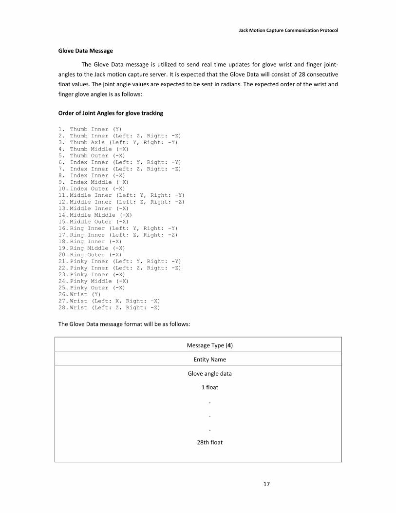
Glove Data Message
The Glove Data message is utilized to send real time updates for glove wrist and finger joint-
angles to the Jack motion capture server. It is expected that the Glove Data will consist of 28 consecutive
float values. The joint angle values are expected to be sent in radians. The expected order of the wrist and
finger glove angles is as follows:
Order of Joint Angles for glove tracking
1. Thumb Inner (Y) 2. Thumb Inner (Left: Z, Right: -Z) 3. Thumb Axis (Left: Y, Right: -Y) 4. Thumb Middle (-X) 5. Thumb Outer (-X) 6. Index Inner (Left: Y, Right: -Y) 7. Index Inner (Left: Z, Right: -Z) 8. Index Inner (-X) 9. Index Middle (-X) 10. Index Outer (-X) 11. Middle Inner (Left: Y, Right: -Y) 12. Middle Inner (Left: Z, Right: -Z) 13. Middle Inner (-X) 14. Middle Middle (-X) 15. Middle Outer (-X) 16. Ring Inner (Left: Y, Right: -Y) 17. Ring Inner (Left: Z, Right: -Z) 18. Ring Inner (-X) 19. Ring Middle (-X) 20. Ring Outer (-X) 21. Pinky Inner (Left: Y, Right: -Y) 22. Pinky Inner (Left: Z, Right: -Z) 23. Pinky Inner (-X) 24. Pinky Middle (-X) 25. Pinky Outer (-X) 26. Wrist (Y) 27. Wrist (Left: X, Right: -X) 28. Wrist (Left: Z, Right: -Z)
The Glove Data message format will be as follows:
Message Type (4)
Entity Name
Glove angle data
1 float
.
.
.
28th float
Jack Motion Capture Communication Protocol
18
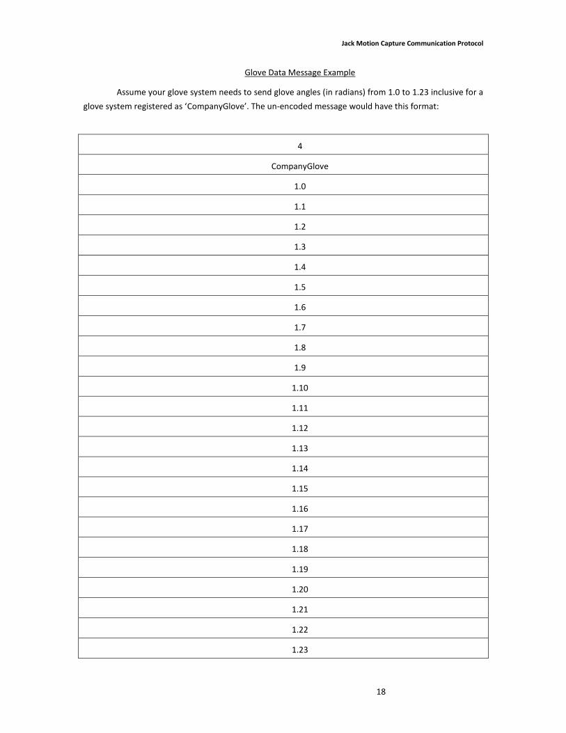
Glove Data Message Example
Assume your glove system needs to send glove angles (in radians) from 1.0 to 1.23 inclusive for a
glove system registered as ‘CompanyGlove’. The un-encoded message would have this format:
4
CompanyGlove
1.0
1.1
1.2
1.3
1.4
1.5
1.6
1.7
1.8
1.9
1.10
1.11
1.12
1.13
1.14
1.15
1.16
1.17
1.18
1.19
1.20
1.21
1.22
1.23

Jack Motion Capture Communication Protocol
19
In this example encoding, the Glove Entity name is ‘CompanyGlove’ and the contained ‘floats’ are
random. The Glove Data message showing the first 128 bytes would look like this:
0:4000|4:72696768|8:74476c6f|12:76650ec|16:0000|20:10ed5030|24:10ecd1ac|28:0006|32:0008|36:c
2389b44|40:434ad185|44:4185da4f|48:c243ff81|52:434b65bc|56:40fa7437|60:c23fa256|64:4348f5ea|
68:413e104c|72:c241b6fa|76:43482db|80:417a89ad|84:c241238e|88:434e84b1|92:4188c01e|96:c245f
5fe|100:434f84d2|104:416fc31f|108:c24968b7|112:434fb77|116:4144233a|120:c24a981|124:434df456
|
Help
For Jack-specific questions concerning the MoCap Communication protocol, please contact the Siemens
Human Simulation Development Group directly.
Please email: [email protected]


