
Commercial In Confidence 1
Introducing MBSE to a Submarine
Concept Design Team
Paul Pearce Senior Systems Engineer
© Deep Blue Tech Pty Ltd 2013. This document contains
information which is owned by or licensed to Deep Blue Tech Pty
Ltd. Unauthorised use, disclosure or reproduction is prohibited.
Contents
• Background
• Recent events
• Current activities
• History behind SE & MBSE in DBT
• Observations and Challenges
• Safety, Risk and Production Considerations
Commercial In Confidence 2

Background
• The Royal Australian Navy (RAN)
currently operate the Collins Class
conventional (diesel-electric)
submarines
• Since 2009, the Australian
Department of Defence has
formed a Project Office (under
project “SEA1000”) to acquire a
successor to the Collins Class.
• A Defence White Paper was also
published by Government in 2009
defining the capabilities required
for a future submarine.
Commercial In Confidence 3
Indicative timeline:
2013/2014: First Pass Approval
2017: Second Pass Approval
~2020: Construction commences

Background (cont.)
• The Government is now considering four broad options for the
Future Submarines*:
– An existing submarine design available off-the-shelf, modified only to meet
Australia’s regulatory requirements (Option 1);
– An existing off-the-shelf design modified to incorporate Australia’s specific
requirements, including in relation to combat systems and weapons (Option 2);
– An evolved design that enhances the capabilities of existing off-the-shelf
designs, including the Collins Class (Option 3); and
– An entirely new developmental submarine (Option 4)
Commercial In Confidence 4
http://www.minister.defence.gov.au/2012/05/03/prime-minister-minister-for-defence-minister-for-defence-
materiel-joint-media-release-next-stage-of-future-submarine-project-announced/ *

SEA 1000 Option 4
• The Australian Government is currently establishing a Defence and
Industry Integrated Project Team (IPT)
• The IPT will develop two costed, scheduled and technically
balanced submarine concept designs for this future submarine
capability
• The IPT will also:
– help better inform Australian industry about the requirements of the
project,
– foster growth of local submarine design capability, and
– determine the capability of progressing with an Australian bespoke
design for SEA 1000 Government First Pass consideration
Commercial In Confidence 5
https://www.tenders.gov.au/?event=public.atm.showClosed&ATMUUID=BF67A210-F51D-4ED0-
D606515BE5DE6BB2

Introducing Deep Blue Tech
• Deep Blue Tech (DBT)
• A wholly owned subsidiary of ASC
• Based in Adelaide, South Australia
• Operates separately and independently from other
ASC activities
• Started in 2007
• Focusses on Australia’s Future Submarine
www.deepbluetech.com.au
Commercial In Confidence 6

Deep Blue Tech in a Nutshell
• Since 2007, DBT has been building an in-
country submarine concept design capability.
– Currently ~ 60 personnel
– An integrated set of tools and processes for
developing submarine designs
– A wide range of skills and levels of experience
• Naval architects to software engineers and draftspeople
• Junior engineers to eminent greybeards
– Established relationships with many potential
providers of systems and technology
Commercial In Confidence 7
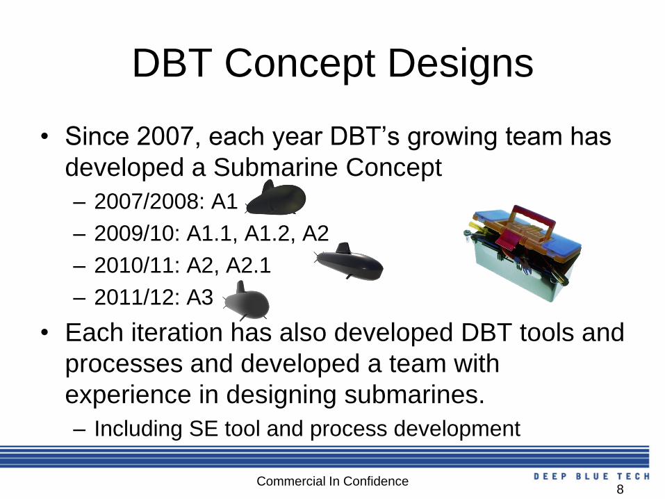
DBT Concept Designs
• Since 2007, each year DBT’s growing team has
developed a Submarine Concept
– 2007/2008: A1
– 2009/10: A1.1, A1.2, A2
– 2010/11: A2, A2.1
– 2011/12: A3
• Each iteration has also developed DBT tools and
processes and developed a team with
experience in designing submarines.
– Including SE tool and process development
Commercial In Confidence 8

Development of SE in DBT
Commercial In Confidence 9
Jan
2008
Jan
2013
Jan
2009
Jan
2010
Jan
2011
Jan
2012
DOORS
Training
Telelogic
DOORS
System Model
in Enterprise
Architect (EA)
Combat System
Model in IBM
Rational Tau
System Model
(new structure)
in EA using
Postgres and
SVN Repository
System Model
(new structure) in
MagicDraw &
Teamwork
Server
SE Guidelines, Reports, Processes, Studies etc.
SETE 2010
Paper SETE/APCOSE
2012 Paper
SIA ST&E
2011
Paper
SysML
Consultation
& Training
SysML
Tool
Training
OMG SysML
Certification
Training
Conf. Paper
Consultant
Tool
LEGEND
Personnel

Early Principles
• Model-based approach to SE
• Adoption of SysML
• SE Process Framework
• Traceability
• Levels of Abstraction (functional, logical,
physical)
• Inspiration from Object-Oriented Systems
Engineering Method (OOSEM)
Commercial In Confidence
10
Commercial In Confidence 11
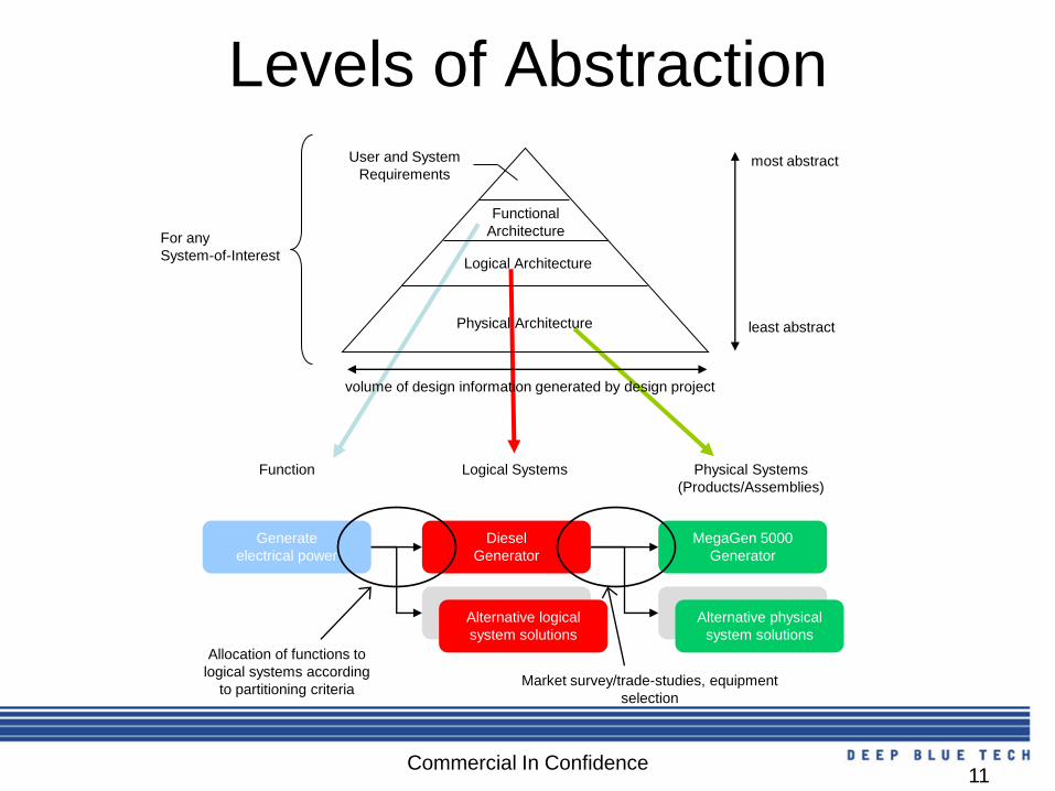
Levels of Abstraction
Physical Architecture
Logical Architecture
Functional
Architecture
User and System
Requirements most abstract
least abstract
volume of design information generated by design project
For any
System-of-Interest
Diesel
Generator
Generate
electrical power
MegaGen 5000
Generator
Alternative logical
system solutions
Alternative physical
system solutions
Function Logical Systems Physical Systems
(Products/Assemblies)
Allocation of functions to
logical systems according
to partitioning criteria Market survey/trade-studies, equipment
selection

Commercial In Confidence 12
Specification & Design Process
Develop Logical &
Physical Architecture in
System Model
Elicit and Analyse Requirements and
Build requirements traceability between
DOORS and System Model

System Modelling Tool
• MagicDraw from No Magic, Inc.
• Selected in March 2012 after comprehensive trade study
– Now deployed in DBT
– Onsite training for team members held in July 2012
– Modelling Guideline to help users bridge gap between tool and process
– Migrated Submarine System Model from superseded tool (Sparx
Systems Enterprise Architect)
• Details
– SysML modelling enabled with SysML plugin
– Common model available to team through Teamwork Server
– Interface with DOORS via Datahub plugin
– Interface with MATLAB/Simulink via ParaMagic plugin
– Interface with PLM system via hyperlinks
Commercial In Confidence
13

Commercial In Confidence 14
Submarine System Model
Organisation

A4
• The current concept iteration in DBT is A4.
• Designed against an internally developed
set of customer requirements
• Continues to build on an integrated toolset
and framework of processes
• Increased project monitoring and planning
Commercial In Confidence 15

Observations: Concept Design
• Early submarine concept design is about numbers
– Sizing and layout: i.e. length, diameter, equipment volumes
– Weight
– Buoyancy
– Energy
• Key requirements identified and used to drive design
– Transit speed of advance (SOA)
– Transit range
– Patrol duration
– Indiscretion ratio
– Sprint Speed (and duration)
– Crew sizes
– Payloads (size and number)
Commercial In Confidence
16

Observations: Concept Design
• Parametric sizing tools are the primary tools used.
• Source of ‘truth’ is a windows directory containing a number of spread-sheets
• Strongly iterative design.
• Sensitivity studies performed where potential trade-spaces are identified (e.g.
compartment layouts, technology options)
• A lot of data passed between individuals verbally and via email.
• Weekly meetings.
Commercial In Confidence 17

Observations: Concept Design
• Contrast with classic SE approach: Requirements & scenarios → functions → systems and their interfaces
Commercial In Confidence 18
The Challenge
• Critically, any MBSE approach must become an
integral part of submarine concept design
activities. How can we do this? – Record trace between DOORS requirements and model
elements in a System Model.
– Provide a common definition of key system properties and
system decompositions
– Document role of key sizing tools
Commercial In Confidence 19

The Evolving Ship Design Spiral
Commercial In Confidence 20
Requirements Analysis &
Architectural Design
Traditional View of
Naval Architects Current DBT SE
Process

Requirements Traceability
Commercial In Confidence 21
Requirements System
Properties
Latest Calculated
Values
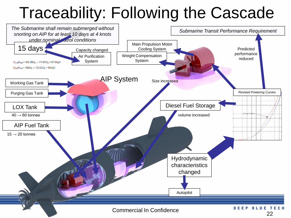
Commercial In Confidence 22
Air Purification
System
Traceability: Following the Cascade The Submarine shall remain submerged without
snorting on AIP for at least 10 days at 4 knots
under nominal patrol conditions
Submarine Transit Performance Requirement
AIP System
15 days
Working Gas Tank
Purging Gas Tank
AIP Fuel Tank
40 → 60 tonnes
15 → 20 tonnes
Hydrodynamic
characteristics
changed
Size increased
volume increased
Predicted
performance
reduced
Diesel Fuel Storage
Main Propulsion Motor
Cooling System
LOX Tank
Weight Compensation
System
Revised Powering Curves
Capacity changed
Autopilot

The Black-Box Specification
Commercial In Confidence 23
properties
functions
Interfaces
Focus of
Concept Design
Focus of SE Team

Observations
• The following are not emphasised during early concept design:
– Functions
• The system decomposition at the submarine level is well-established in DBT
• Building a pure functional decomposition from scenarios and formulating a
different list of systems appears unnecessary.
• Most domain engineers involved in the concept design don’t see the benefit
of such an abstract representation.
– Interfaces
• In general, early concept design locates, but does not ‘connect’ the boxes.
This detail will be added in the Preliminary Design phase.
• Solution:
– The Black-Box Specification provides a placeholder to accumulate properties,
functions and interfaces for any system of interest (whole-of-submarine, sub-
systems or components)
Commercial In Confidence 24
Roles and Responsibilities
• In DBT, there are three broad roles: – ‘Domain’ Engineers: responsible for a part of the
system design, such as a complete sub-system.
– Systems Engineers: custodians of the SE process,
managing requirements and providing SE guidance to
the team
– Interdisciplinary Engineers, such as reliability, cost,
safety and signatures, working across systems.
Commercial In Confidence 25

Ownership of Design
• Ownership of design by domain engineers is fundamental.
Commercial In Confidence 26
Systems
Engineers
Functions
Logical
Design
Physical
Design
Requirements
Domain
Engineers
Domain
Engineers
Common approach to
SE in Industry DBT Approach
(supported by Systems Engineers)
handover
System of
Interest
Incre
asin
g D
eta
il

Implications of DBT Approach
• At the ‘top-end’ of the design, domain
engineers need to think like systems
engineers
– Abstract away unnecessary details
– Define the problem before the solution
– Traceability is second-nature
Commercial In Confidence 27

Example #1: Submarine Weight
Compensation System
Commercial In Confidence 28
Very abstract (no
mention of pumps
or valves yet), but
still some solution
involved: i.e. sea-
water used to
adjust buoyancy
via a tank (could
have said ‘storage
assembly’)
It is possible to
make the definition
so abstract it
becomes
meaningless.

Example #2: Submarine Weight
Compensation System
Commercial In Confidence 29
More detail – ‘secondary’ functions included e.g. drain & vent, recirculation loop for
pumps, multiple tanks, interconnects with other systems
Implications of DBT Approach
• In DBT, domain engineers are expected to
do the system modelling supported by
systems engineers with systems modelling
skills and tools.
Commercial In Confidence 30

Other considerations
• Safety Case
• Technology Readiness Levels
• Production
Commercial In Confidence 31

32
Supporting the Safety Case • Claim-Argument-Evidence (CAE) approach
• Create CAE model
in SysML (pictured)
or
• Link diagrams and
elements in SysML
model, to a CAE
model in another
tool, as supporting
evidence
Diagram adapted from M.C. Hause, F. Thom, An Integrated
Safety Strategy to Model Driven Development with SysML, 2007
All relevant seaworthiness
requirements have been
identified completely and
correctly
Argument by showing
extreme improbability of
overlooking relevant
requirements
Argument by showing
assumptions used to
derive requirements were
correct
Relevant
seaworthiness
requirements satisfy
mandated standards
where applicable
Seaworthiness
requirements
specified
Relevance of
seaworthiness
requirements
assessed by
competent staff
Assumptions are
proven correct by
sea trial
Basis of
Certification
Document
Competencies
of staff used to
filter seaworthiness
requirements
Competencies
of specialists used to
vet and approve
seaworthiness
requirements
Assumptions
proven by
sea trial
DEFAUST
5000

33
System Readiness Level (SRL)
Assessment
Building a novel system
from proven components?
Building a non-novel system
from novel components?

34
Transition from System to Product
system-oriented
breakdown product-oriented
breakdown
ibd [SysML Internal Block] Stirling AIP System [AIP System Schematic]
«block»
Stirling AIP System
«flowPort»
Electrical
Power Output
:Power
«flowPort»
Exhaust :Sea
Water
«flowPort» Cooling
Water In :Fresh
Water
«flowPort»
Cooling
Water Out :
Fresh Water
Operator Control
«flowPort» Sea
Water Inlet :Sea
Water
«flowPort»
Waste Water :
Water
: Stirl ing Module
«flowPort»
Power Out
:Power
«flowPort»
Exhaust :Carbon
Dioxide
«flowPort» Fuel
In :AIP Fuel
«flowPort» Waste
Water :Water
«flowPort» Cooling
Water Out :Fresh
Water
«flowPort» Cooling
Water In :Fresh
Water
«flowPort» Helium
In :Helium
«flowPort» Nitrogen
In :Nitrogen
«flowPort» Oxygen
In :Oxygen
: Power Converter
«flowPort»
Power Out
:Power
«flowPort»
Power In :
Power
: LOX System
: Stirl ing Module Fuel System
: Fuel Pump
«flowPort»
Outlet :AIP
Fuel
«flowPort»
Inlet :AIP
Fuel
: Fuel Tank
«flowPort»
Outlet :AIP
Fuel
: Oxygen Tank
«flowPort» Outlet :
Liquid Oxygen (LOX)
: CO2 Dissolver
«flowPort» Exhaust Out :Sea
Water
«flowPort» Water
Inlet :Sea Water
«flowPort» Exhaust
In :Carbon Dioxide
: Helium Tank
«flowPort»
Outlet :Helium
: Evaporator
«flowPort»
Water Out :
Fresh Water
«flowPort» Water In
:Fresh Water
«flowPort» Oxygen
Out :Oxygen
«flowPort» Liquid
Oxygen In :Liquid
Oxygen (LOX)
: Nitrogen Tank
«flowPort» Outlet :
Nitrogen
: Pressure Intensifier«flowPort» Outlet :
Sea Water
«flowPort» Inlet :
Sea Water
1. Control l ines not shown
2. Cold Box, Safety Vent and Fill ing Lines for LOX
System not shown
3. Valves not shown
4. AIP Auxiliary Cabinet also required to enclose
Fuel pump and associated valves etc, control
modules for each Stirl ing Engine Module and
controls (including valves) for gas lines
5. The requirement for redundancy in the gas and
fuel pipework and control systems should be
investigated
6. Reusing the waste heat from the Stirl ing Engine
Modules should be investigated
7. Reusing the cooling from converting LOX to GOX
should be investigated
8. Line for releasing GOX to the atmosphere not
shown
Breaker Cabinet
«block» AIP Fuel
«block» Carbon Dioxide
«block» Fresh Water
«block» Fresh Water
«block» Fresh Water
«block» Fresh Water
«block» Water
«valueType» Power«valueType» Power
«block» Nitrogen
«block» Helium
«block» AIP Fuel
«block» Oxygen
«block» Sea Water
«block» Sea Water
«block» Sea
Water
«block» Liquid
Oxygen (LOX)
Big Challenge:
managing and
tracing change
between SysML and
3D CAD models

Moving forward…
• Increasing perceived usefulness of SE to
Naval Architects who are leading the
design
• Leveraging the design process
• Promoting the System Model to help the
team specify and develop submarine
designs.
Commercial In Confidence
35

Commercial In Confidence 36
Questions?


![[MBSE 2021] ESA MBSE Evolution: From ESA SysML Toolbox to](https://cdn.vdocuments.us/doc/165x107/61f003bcc08c1e795d73caa3/mbse-2021-esa-mbse-evolution-from-esa-sysml-toolbox-to-.jpg)
