
D E S C R I P T I O N
Magnetrol® flow switches are highly reliable devices
utilized to sense the start or stop of flow in horizontal
pipelines containing oil and petroleum derivatives,
chemicals, water, or air.
Vane-actuated Model F10 switches are used on gas or
liquid flow applications in 2" or larger line sizes.
Disc actuated Model F50 switches are in-line type used
for sensing clean liquids in 2" or smaller line sizes.
F E A T U R E S
• Actuation on increasing or decreasing flow
• Special sensing elements for non-standard or high
flow applications
• Designed for horizontal pipe applications
• Available switch styles include dry contact,
hermetically sealed and pneumatic
Mo d e l F 1 0
• Field adjustable
• Low pressure drop
• Process pressures to 1000 psig (69 bar)
• Process temperatures to +450° F (+232° C)
• Standard flow vanes for 2" thru 10" flow lines
Mo d e l F 5 0
• No calibration required
• Bronze or stainless steel construction
• Process pressures to 1150 psig (79.2 bar)
• Process temperatures to +750° F (+399° C)
• Bodies for flow lines from 3⁄4" to 2"
A P P L I C A T I O N S
• Pump staging or failure
• Pipeline flow detection
• Valve failure
• Loss of pipeline flow
• Pipe blockage/rupture
• Pump inlet flow protection
• Check valve blockage/leakage
• Alarm on eyewash or shower safety station
F10 & F50
Flow Switches
Model F10
Model F50

2
Magnet
ReturnSpring
Pivot
T E C HNO LOG YM o d e l F 1 0
Flow through the horizontal pipeline causes the pivoted
vane assembly to swing in the direction of the flow. The
vane assembly lifts an attraction sleeve which in turn
causes the magnet to pull in and actuate the switch.
The O-ring sealed adjusting screw in the top of the
enclosing tube compresses the range spring located
above the attraction sleeve. Turning the adjusting screw
clockwise increases the flow rate at which the switch
actuates. Adjustments can be made while the flow switch
is in service.
Actuatingvane
Adjustingscrew
MagneticsleeveSwing out
position
Returnspring
Pivot
The rate of flow through the valve body raises or lowers
the disc. This in turn raises or lowers the magnetic sleeve
within its sealed non-magnetic enclosing tube. On an
increasing flow rate, the magnetic sleeve rises into the
field of the permanent magnet, located outside the
enclosing tube, actuating the attached switch mechanism.
When the flow rate drops below the rate for which the
flow disc is calibrated, a reversal of this action occurs.
Enclosingtube
(non-magnetic)
Swing inposition
Sleeve(magnetic)
Magnet
Flow disc
Position with actuating flow present
ReturnSpring
Pivot
Switch mechanism
Swing outposition
Returnspring
Pivot
No-flow position
Mo d e l F 5 0

3
T Y P I C A L A P P L I C A T I O N S
PumpprotectionOverflow
tank
Leak detection
Primarytank
Input line
Additive flow
FLOW
FLOW
Overflow detection
FLOW
MOD E L F 5 0 P R E S S U R E D R O P A C RO S S S W I T C H
" NPT connectionM odel F50 w ith
" NPT connection M odel F50 w ith 2" NPT connectionM odel F50 w ith 1
20
15
10
5
00 50 100 150 200
Pre
ss
ure D
rop (
psi)
Wa ter Flow Rate (GPM )
M odel F50 w ith 1" NPT connection
20
15
10
5
00 50 100 150 200
Pre
ss
ure D
rop (
psi)
Wa ter Flow Rate (GPM )
20
15
10
5
00 50 100 150 200
Pre
ss
ure D
rop (
psi)
Wa ter Flow Rate (GPM )
20
15
10
5
00 50 100 150 200
Pre
ss
ure D
rop (
psi)
Wa ter Flow Rate (GPM )

4
SWITCH ENCLOSURES
• TYPE 4X/7/9 aluminumenclosures
• Designed to meet Class I, Div. 1,Groups C & D and Class I,Div. 1 Group B
• Optional housing heaters anddrains available for some enclosures
• Pneumatic switch mechanismsavailable with a NEMA 1 enclosure
SERIES HS & F HERMETICALLY SEALED SWITCHES
• Ideal for use in salt and other corrosiveatmospheres
• Series “HS” is positively pressurizedcapsules for entire mechanism and contacts
• Process temperatures to +750° F (+399° C)
SERIES J & K PNEUMATIC SWITCHES
• Suited for applications where electricalpower is not available
• Bleed and non-bleed designs
• Process temperatures to+400° F (+204° C)
S P E C I F I C A T I O N S
S W I T C H M E C H AN I S M S A N D E N C L O S U R E S
BASIC ELECTRICAL RATINGS
VoltageSwitch Series and Non-Inductive Ampere Rating
B C D F HS
120 VAC 15.00 15.00 10.00 0.25 5.00
240 VAC 15.00 15.00 — — 5.00
24 VDC 6.00 10.00 10.00 4.00 5.00
120 VDC 0.50 1.00 10.00 0.30 0.50
240 VDC 0.25 0.50 3.00 — 0.25
S P E C I F I C G R A V I T Y C O R R E C T I O N
To determine the actuating flow rates for liquids other
than water (approximate viscosity of 20 centistokes or
less), a specific gravity correction factor must be applied
to the water flow rates given in the table. For gas/air
applications, consult factory.
Model F10 Example:
The maximum adjustment for an increasing flow rate on
a Model F10 with a liquid specific gravity of .70 in an 8"
line is: 230 GPM x 1.20 = 276 GPM.
Model F50 Example:
The actuation flow rate of a liquid with specific gravity
of 1.10 on increasing flow for a Model F50 with a 1"
body and an “E” size disc is: 5.5 GPM x 0.95 = 5.2 GPM.
Specific Gravity Multiplication Factor Specific Gravity Multiplication Factor
.40 1.58 .95 1.03
.45 1.49 1.00 1.00
.50 1.41 1.05 .98
.55 1.35 1.10 .95
.60 1.29 1.15 .93
.65 1.24 1.20 .91
.70 1.20 1.25 .89
.75 1.15 1.30 .88
.80 1.12 1.35 .86
.85 1.08 1.40 .85
.90 1.05 1.45 .83
SERIES B, C & D DRY CONTACT SWITCHES
• Dry contact for applicationswhere mercury must be avoided
• Designs for AC and DCcurrent applications
• Process temperaturesto +450° F (+232° C)

5
AGENCY MODEL APPROVAL CATEGORIES
FM F10-XXXX-XXX with an electric switch mechanism and a housing Class I, Div 1, Groups C & DF50-XXXX-XXX listed as TYPE 4X/7/9 Class II, Div 1, Groups E, F & G
F10-XXXX-XXX with an electric switch mechanism and a housing Class I, Div 1, B, C & DF50-XXXX-XXX listed as TYPE 4X/7/9 Class I, Div 1, Group B Class II, Div 1, Groups E, F & G
CSA F10-XXXX-XXX with a Series HS or F electric switch mechanism Class I, Div 2, Group BF50-XXXX-XXX and a housing listed as CSA TYPE 4X
F10-XXXX-XXX with an electric switch mechanism and a housing Class I, Div 1, Groups C & D F50-XXXX-XXX listed as TYPE 4X/7/9 Class II, Div 1, Groups E, F & G
F10-XXXX-XXX with an electric switch mechanism and a housing Class I, Div 1, Groups B, C & DF50-XXXX-XXX listed as TYPE 4X/7/9 Class I, Div 1, Group B Class II, Div 1, Groups E, F & G
ATEX/ IEC Ex ➀ F10-XXXX-XXX with an electric switch mechanism and an ATEX II 2 G EEx d IIC T6F50-XXXX-XXX ATEX housing 94/9/EC
IEC Ex Ex d IIC T6IP 66
CE F10-XXXX-XXX Low Voltage Directives 2006/95/EC Installation Category IIF50-XXXX-XXX Per Harmonized Standard: Pollution Degree 2
EN 61010-1/1993 & Amendment No. 1
AG E N C Y A P P R O V A L S
➀ IEC Installation Instructions:
The cable entry and closing devices shall be Ex d certified suitable for the conditions of use and correctly installed.
For ambient temperatures above +55° C or for process temperatures above +150° C, suitable heat resistant cables shall be used.
Heat extensions (between process connection and housing) shall never be insulated.
Special conditions for safe use:
When the equipment is installed in process temperatures higher than +85° C the temperature classification must be reducedaccording to the following table as per IEC60079-0.
Maximum Process
Temperature
Temperature
Classification
< 85° C T6
< 100° C T5
< 135° C T4
< 200° C T3
< 300° C T2
< 450° C T1
These units are in conformity with IECEx KEM 05.0020XClassification Ex d IIC T6Tambient -40° C to +70° C
6
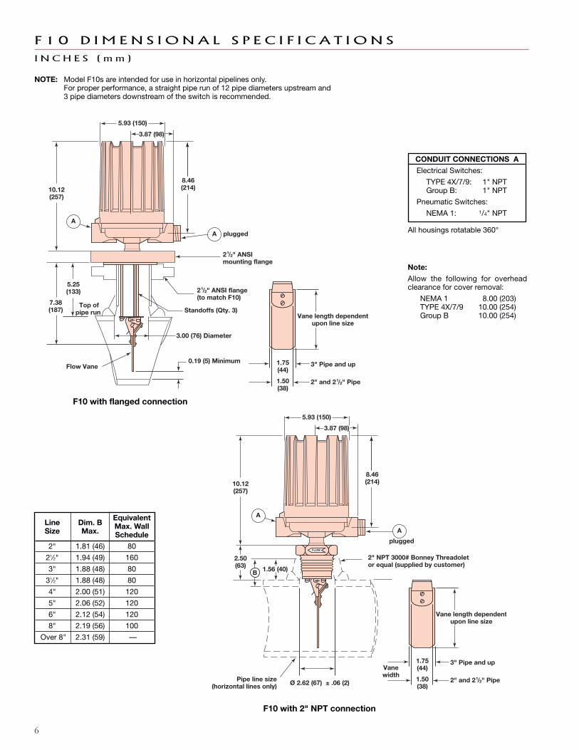
F 1 0 D I M E N S I O N A L S P E C I F I C A T I O N S
I N C H E S ( m m )
Ø 2.62 (67) ± .06 (2)
Vane length dependentupon line size
1.75(44)
1.50(38)
3" Pipe and up
2" and 21/2" Pipe
2" NPT 3000# Bonney Threadoletor equal (supplied by customer)
Pipe line size(horizontal lines only)
Vanewidth
FLOW
A
5.93 (150)
3.87 (98)
8.46(214)
A
plugged
1.56 (40)
2.50(63)
10.12(257)
B
CONDuIT CONNECTIONS A
Electrical Switches:
TYPE 4X/7/9: 1" NPTGroup B: 1" NPT
Pneumatic Switches:
NEMA 1: 1/4" NPT
All housings rotatable 360°
Line Dim. BEquivalent
Size Max.Max. WallSchedule
2" 1.81 (46) 80
21⁄2" 1.94 (49) 160
3" 1.88 (48) 80
31⁄2" 1.88 (48) 80
4" 2.00 (51) 120
5" 2.06 (52) 120
6" 2.12 (54) 120
8" 2.19 (56) 100
Over 8" 2.31 (59) —
3.00 (76) Diameter
21/2" ANSI flange(to match F10)
21/2" ANSImounting flange
Flow Vane0.19 (5) Minimum
5.25(133)
Top of pipe run
7.38(187)
1.75(44)
1.50(38)
3" Pipe and up
2" and 21/2" Pipe
A
5.93 (150)
3.87 (98)
8.46(214)
A plugged
10.12(257)
Standoffs (Qty. 3)Vane length dependent
upon line size
Note:
Allow the following for overheadclearance for cover removal:
NEMA 1 8.00 (203)TYPE 4X/7/9 10.00 (254)Group B 10.00 (254)
F10 with flanged connection
F10 with 2" NPT connection
NOTE: Model F10s are intended for use in horizontal pipelines only.For proper performance, a straight pipe run of 12 pipe diameters upstream and3 pipe diameters downstream of the switch is recommended.
7
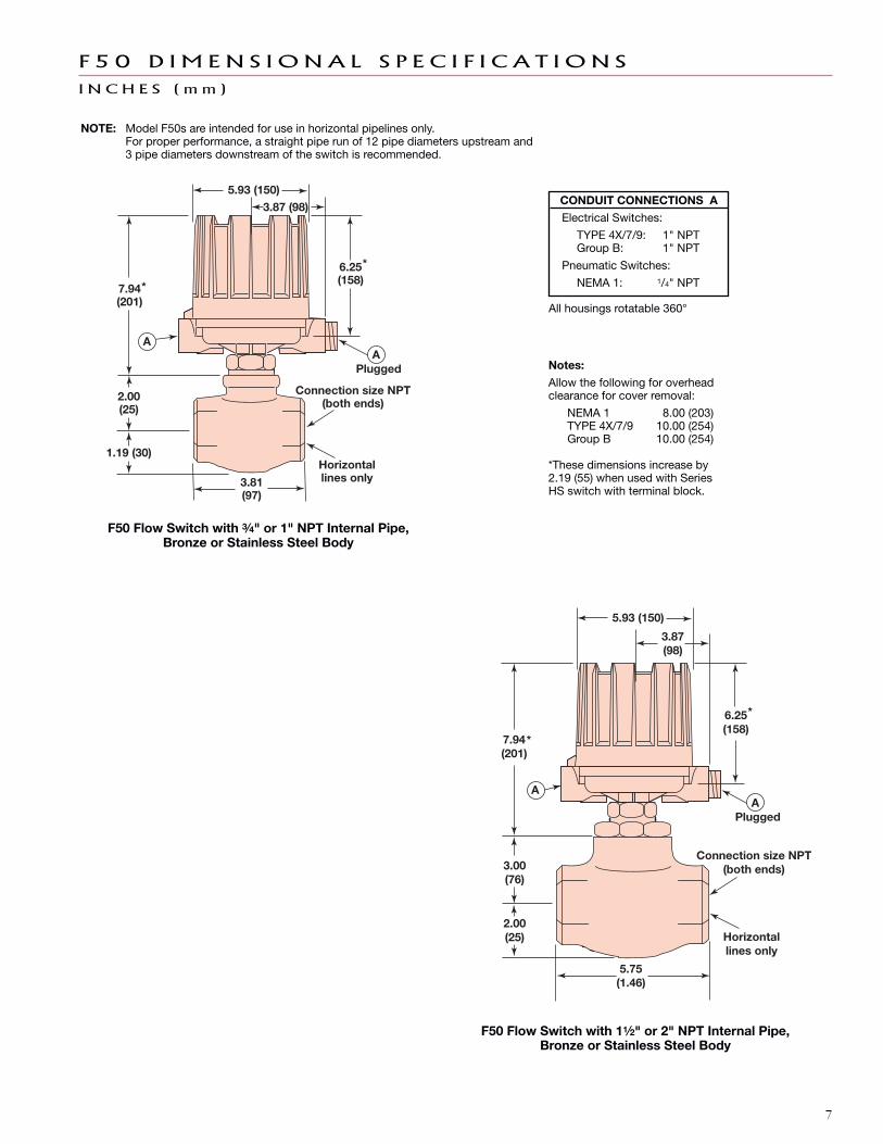
F 5 0 D I M E N S I O N A L S P E C I F I C A T I O N S
I N C H E S ( m m )
6.25(158)
*
7.94(201)
*
3.00(76)
2.00(25)
5.75(1.46)
Horizontallines only
Plugged
AA
Connection size NPT(both ends)
3.87(98)
5.93 (150)
F50 Flow Switch with 3⁄4" or 1" NPT Internal Pipe,Bronze or Stainless Steel Body
6.25(158)
*
3.87 (98)5.93 (150)
7.94(201)
*
2.00(25)
1.19 (30)
3.81(97)
Horizontallines only
PluggedA
Connection size NPT(both ends)
A
F50 Flow Switch with 11⁄2" or 2" NPT Internal Pipe,Bronze or Stainless Steel Body
NOTE: Model F50s are intended for use in horizontal pipelines only.For proper performance, a straight pipe run of 12 pipe diameters upstream and3 pipe diameters downstream of the switch is recommended.
CONDuIT CONNECTIONS A
Electrical Switches:
TYPE 4X/7/9: 1" NPTGroup B: 1" NPT
Pneumatic Switches:
NEMA 1: 1/4" NPT
All housings rotatable 360°
Notes:
Allow the following for overheadclearance for cover removal:
NEMA 1 8.00 (203)TYPE 4X/7/9 10.00 (254)Group B 10.00 (254)
*These dimensions increase by2.19 (55) when used with SeriesHS switch with terminal block.

8
➀ Based upon Schedule 40 pipe.
➁ For higher flow rates consult factory.
A C T U A T I N G F L OW R A T E S ( W A T E R S E R V I C E )
Model F10 units may be adjusted in service to actuate
within the minimum and maximum flow rates given
below. A specific gravity correction factor is applied for
liquids other than water (1.00 specific gravity).
Pipe Line Size ➀ Flow Increase (GPM) Flow Decrease (GPM)
Inches Minimum Maximum ➁ Minimum Maximum
2 21 63 16 48
21⁄2 26 74 20 56
3 32 88 24 65
31⁄2 38 100 28 75
4 45 120 33 85
5 61 150 43 110
6 79 180 55 130
8 120 230 82 160
10 170 310 110 210
12 230 380 150 250
14 270 430 170 280
16 340 510 220 320
18 430 590 270 370
20 520 690 320 430
22 620 780 380 480
24 730 900 450 550
26 850 1030 520 620
28 980 1160 590 700
30 1110 1290 670 780

9
Maximum Maximum BleedSupply Process Orifice
Switch Pressure Temperature Diameter
Description psig Bar ° F ° C Inches mm NEMA 1
Series J100 7 +400 +204 .63 1.6 JGF
60 4 +400 +204 .94 2.3 JHFBleed Type60 4 +400 +204 .55 1.4 JJF
Series K 100 7 +400 +204 — — KOFNon-Bleed 40 3 +400 +204 — — KOH
Vane Sized for Flow Line
Connection Type 2" 4" 6" 8" 10"
2" NPT D22 D24 D26 D28 D20
21⁄2" 150 lb. ANSI raised face flange n/a E54 E56 E58 E50
21⁄2" 300 lb. ANSI raised face flange n/a E64 E66 E68 E60
21⁄2" 600 lb. ANSI raised face flange n/a E74 E76 E78 E70
Mounting Connection Trim Magnetic Sleeve Pressure
F10-1 Carbon steel 304 and 316 stainless steel 316 stainless steel 1000 psig @ +450° F (69 bar @ +232° C)
F10-3 304 stainless steel 304 and 316 stainless steel 316 stainless steel 1000 psig @ +450° F (69 bar @ +232° C)
F10-4 316 stainless steel 316 stainless steel 316 stainless steel 1000 psig @ +450° F (69 bar @ +232° C)
Models available for quick shipment, usually within one week after factoryreceipt of a complete purchase order, through the Expedite Ship Plan (ESP)
MODEL NUMBER CODE
PIPELINE CONNECTION
PNEUMATIC SWITCH MECHANISM AND ENCLOSURE
Consult factory for flow lines above 10" or larger flange sizes.
F 1 0 MO D E L N UM B E R
ELECTRIC SWITCH MECHANISM AND ENCLOSURE
➀ Process temperatures based on +100° F(+38° C) ambient.
➁ Uncontrolled housing heater or drain availablein TYPE 4X/7/9 enclosures.
➂ Consult factory for TYPE 4X/7/9 cast ironhousings.
On flanged models, standoffs are carbon steel with Model F10-1 and 316 stainless steel on Models F10-3 and F10-4.
Consult factory for Steam applications.
TYPE 4X/7/9Maximum AluminumProcess One Class I, Class I,
Temperature Set Div.1 Div. 1Switch Description ° F° C Point Grps C & D Grp B ATEX
Series B snap +250 (+121) SPDT BKB BKK BC9DPDT BNB BNK BF9
Series C snap +450 (+232)SPDT CKB CKK CC9DPDT CNB CNK CF9
Series D snap +250 (+121) SPDT DKB DKK DC9for DC current applications DPDT DNB DNK DF9
Series HS 5 amp SPDT HMJ HMK n/ahermetically sealed snap +450 (+232)with wiring leads DPDT HMS HMT n/a
Series HS 5 amp SPDT HM3 HM4 HA9hermetically sealed snap +450 (+232)with terminal block DPDT HM7 HM8 HB9
➀➁ ➂

10
Models available for quick shipment, usually within one week after factoryreceipt of a complete purchase order, through the Expedite Ship Plan (ESP)
MODEL NUMBER CODE
ACTUATING FLOW RATE
F 5 0 MO D E L N UM B E R
PNEUMATIC SWITCH MECHANISM AND ENCLOSURE
PIPE SIZE
Body Trim Magnetic Sleeve Pressure Ratings
F50-1 Bronze 300 series 400 series 400 psi @ +100° F (27.6 bar @ 38° C)stainless steel stainless steel 200 psi @ +500° F maximum (13.8 bar @ 260° C maximum)
F50-4 316 stainless steel 316 stainless steel 316 stainless steel 1150 psi @ +100° F (79.2 bar @ 38° C)600 psi @ +750° F maximum (41.3 bar @ 399° C maximum)
A2 3⁄4" pipe size with 3⁄4" NPT connections
B2 1" pipe size with 1" NPT connections
C2 11⁄2" pipe size with 11⁄2" NPT connections
D2 2" pipe size with 2" NPT connections
Actuating Flow Rate, GPM Water Flow, Increasing and Decreasing Rate
Pipe size A B C D E F
3⁄4" NPT n/a 1.1 increasing 1.6 increasing 2.3 increasing 3.4 increasing 4.9 increasingn/a 0.8 decreasing 1.2 decreasing 1.8 decreasing 2.6 decreasing 3.7 decreasing
1" NPT 1.0 increasing 1.7 increasing 2.5 increasing 3.7 increasing 5.5 increasing 7.1 increasing0.8 decreasing 1.4 decreasing 2.1 decreasing 3.0 decreasing 4.5 decreasing 5.8 decreasing
11⁄2" NPT 1.3 increasing 2.7 increasing 4.7 increasing 7.6 increasing 12.3 increasing 21.1 increasing1.1 decreasing 2.3 decreasing 4.0 decreasing 6.5 decreasing 10.3 decreasing 17.9 decreasing
2" NPT 1.9 increasing 3.1 increasing 5.1 increasing 8.4 increasing 14.3 increasing 24.8 increasing1.6 decreasing 2.7 decreasing 4.3 decreasing 7.1 decreasing 12.1 decreasing 21.0 decreasing
Max. ➀ ➁
Process Maximum BleedTemp. Supply Orifice Body Pipe Size
Switch Description ° F (° C) Pressure Diameter Material (NPT) Flow Rate NEMA 13⁄4" or 1" A thru F
JDG100 psig 0.63" Bronze
11⁄2" or 2"A thru D
(7 bar) (1.6 mm) E and FJDE
Series J bleed type+550 Stainless Steel 3⁄4" thru 2" A thru F(+288) 3⁄4" or 1" A thru F
JEG60 psig 0.94" Bronze
11⁄2" or 2"A thru D
(4 bar) (2.4 mm) E and FJEE
Stainless Steel 3⁄4" thru 2" A thru F100 psig
n/aBronze 11⁄2" or 2" E and F
KOESeries K non-bleed type
+550 (7 bar) Stainless Steel 3⁄4" thru 2" A thru F(+288) 40 psig
n/a Bronze3⁄4" thru 1" A thru F
KOG(3 bar) 11⁄2" or 2" A thru D

11
ELECTRIC SWITCH MECHANISM AND ENCLOSURE
F 5 0 MO D E L N UM B E R c o n t i n u e d
Switch Description
Maximum ProcessTemperature
Range° F (° C)
OneSet
PointBody
MaterialPipe Size
(NPT)FlowRate
TYPE 4X/7/9Aluminum
Class I, Div 1 Class I, Div 1Grps C & D Grp B ATEX
Series B snap -40 to +250(-40 to +121)
SPDTBronze
3⁄4" or 1" A thru F BKP BKT BAC11⁄2" or 2"
A thru DE and F BKQ BKS BA9
Stainless Steel 3⁄4" thru 2" A thru F
DPDTBronze
3⁄4" or 1" A thru F BNP BNT BBC11⁄2" or 2"
A thru DE and F BNQ BNS BB9
Stainless Steel 3⁄4" thru 2" A thru F
Series C snap -40 to +450(-40 to +232)
SPDTBronze
3⁄4" or 1" A thru F CKP CKT CAC11⁄2" or 2"
A thru DE and F CKQ CKS CA9
Stainless Steel 3⁄4" thru 2" A thru F
DPDTBronze
3⁄4" or 1" A thru F CNP CNT CBC11⁄2" or 2"
A thru DE and F CNQ CNS CB9
Stainless Steel 3⁄4" thru 2" A thru F
Series D snap forDC current applications
-40 to +250(-40 to +121)
SPDTStainless Steel 3⁄4" thru 2" A thru F DKQ DKS DA9
DPDT DNQ DNS DB9
Series F snap -40 to +750(-40 to +399)
SPDTBronze
3⁄4" or 1" A thru F FKP FKT FAC11⁄2" or 2"
A thru DE and F FKQ FKS FA9
Stainless Steel 3⁄4" thru 2" A thru F
DPDTBronze
3⁄4" or 1" A thru F FNP FNT FBC11⁄2" or 2"
A thru DE and F FNQ FNS FB9
Stainless Steel 3⁄4" thru 2" A thru F
Series HS snap 5 amphermetically sealed w/wiring leads
-50 to +550(-46 to +288)
SPDT Bronze 11⁄2" thru 2"➃ A thru F HMC HEK n/aDPDT Bronze 11⁄2" thru 2"➃ A thru F HMF HET n/a
Series HS snap 5 amphermetically sealed w/terminal block
-50 to +550(-46 to +288)
SPDT Bronze 11⁄2" thru 2"➃ A thru F HM3 HM4 HA9
DPDT Bronze 11⁄2" thru 2"➃ A thru F HM7 HM8 HB9
➀ ➁
➂
➂
➀ Process temperatures based on -40° to +160° F(-40 ° to +71° C).
➁ Bronze models are rated to a maximum processtemperature of +500° F (+260° C).Stainless steel models are limited to the maximumtemperature of the selected switch mechanism.
➂ On steam applications, temperature down-rated to+400° F (+204° C) process at +100° F (+40° C)ambient.
➃ On models with bronze bodies 3⁄4" or 1" NPT pipesizes, consult factory for HS switches.

BuLLETIN: 47-116.25
EFFECTIVE: February 2015
SuPERSEDES: November 2014
The quality assurance system in place at
MAGNETROL guarantees the highest level of
quality throughout the company. MAGNETROL
is committed to providing full customer satisfac-
tion both in quality products and quality service.
The MAGNETROL quality assurance system is
registered to ISO 9001 affirming its commitment
to known international quality standards provid-
ing the strongest assurance of product/service
quality available.
Several F10 and F50 Flow Switches are available
for quick shipment, usually within one week after
factory receipt of a purchase order, through the
Expedite Ship Plan (ESP).
To take advantage of ESP, match the color coded
model number codes in the selection charts
(standard dimensions apply).
ESP service may not apply to orders of ten units
or more. Contact your local representative for lead
times on larger volume orders, as well as other
products and options.
Expedite
Ship
Plan
All MAGNETROL mechanical level and flow con-
trols are warranted free of defects in materials or
workmanship for five full years from the date of
original factory shipment.
If returned within the warranty period; and, upon
factory inspection of the control, the cause of the
claim is determined to be covered under the
warranty; then, MAGNETROL will repair or
replace the control at no cost to the purchaser (or
owner) other than transportation.
MAGNETROL shall not be liable for misapplica-
tion, labor claims, direct or consequential damage
or expense arising from the installation or use of
equipment. There are no other warranties ex-
pressed or implied, except special written
warranties covering some MAGNETROL products.
705 Enterprise Street • Aurora, Illinois 60504-8149 • 630-969-4000 • Fax [email protected] • www.magnetrol.com
Copyright © 2015 Magnetrol International, Incorporated. All rights reserved. Printed in the USA.Performance specifications are effective with date of issue and are subject to change without notice.
QUA L I T Y
E S P
W A R R A N T Y
For additional information on the Models F10 and F50, see Instruction Manual 47-602.
MAGNETROL & MAGNETROL logotype are registered trademarks of MAGNETROL INTERNATIONAL, INCORPORATED.


