
DRUS: A New Proposed Interoperable DRM Hardware Software Solution
System
By
Amr Mohamed Samir Tosson
A Thesis Submitted to the Faculty of Engineering at Cairo University
in Partial Fulfillment of the Requirements for the Degree of
Master of Science In
Electronics
Under the supervision of
M.F.Abu El-Yazeed Hossam A.H. Fahmy Professor Assistant Professor Elec. and Comm. Dept. Elec. and Comm. Dept. Faculty of Engineering, Cairo University, Giza, Egypt
December 2008

Abstract The advent of consumer digital media products has vastly increased the concerns of
copyright-dependent organizations within the music and movie industries.
While analog media inevitably loses quality with each copy generation, digital media files
may be duplicated an unlimited number of times with no degradation in the quality of
subsequent copies. The advent of personal computers as household appliances has made it
convenient for consumers to convert media originally in a physical/analog form or a
broadcast form into a digital form, combined with the Internet and popular file sharing tools,
has made unauthorized distribution of copies of copyrighted digital media much easier.
The Digital Rights Management (DRM) field was thus spawned to prevent unauthorized
access to digital content. The DRM solutions exist as either proprietary products owned by
companies or as open standards.
Most of the implemented DRM solutions suffer mainly from interoperability issue.
The main problem with interoperability is that it could the competition in the market through
locking the users to certain products only.
In this work, we propose a new DRM system which overcomes the interoperability issue
which exists in today’s DRM products by creating a new system which supports basic DRM
functionalities and which can be extended for each specific service and functionality.
This thesis is organized as follows: In chapter I we introduce the DRM technology and its
different fields. A quick review of the current DRM solutions is provided in chapter 2.
The architecture and the different functionalities of our proposed system are explained in
details in chapter 3. In chapter 4, we discuss the simulation results of the implemented
hardware controller of our system. Chapter 5 summarizes our conclusion and introduces some
points that need more research.
ii

Acknowledgment
A word of thanks to ALLAH, the source of all knowledge, by whose abundant grace, this
work has come to life.
I wish to express my gratitude to those who generously helped me in carrying out this work
with their knowledge, valuable advices and kind encouragements.
I would like to express my sincere thanks, deep gratitude, and extreme appreciation to Prof.
Dr. Mohamed Fathy, Professor of Electronics and communication, Faculty of Engineering,
Cairo University, for his remarkable help, indispensable advice and encouragement
throughout this work.
I wish to express my deep everlasting gratitude to Dr. Hossam Fahmy, Lecturer of
Electronics and communication, Faculty of Engineering, Cairo University, not only for his
fruitful advice, but also for his constant valuable guidance and for his tremendous effort in the
presentation of this work.
Also, I would like to thank my company Mentor Graphics for its support and specially my
colleagues and my managers for their wonderful understanding and help.
Last but not least, I am deeply thankful and always indebted to my parents and my sister,
who were always there for me, supporting, encouraging and loving me.
iii

Contents
Abstract ……………………………………………………… Ii Acknowledgment …………………………………………….. Iii
1 Introduction ………………………………………………….. 1-4 2 Literature Review ……………………………………………
2.1 Companies DRM Products …………………………………………
5-26 5-12
2.1.1 Content Guard Corp. …………………………………..
2.1.2 Intertrust Technologies Corp. ………………………….
2.1.3 Macrovision Corp. …………………………………….
2.1.4 Microsoft Corp. ………………………………………..
2.1.5 RealNetworks Corp. …………………………………...
2.1.6 Sony Corp. ……………………………………………..
2.1.7 IBM Corp. ……………………………………………...
6
7
8
8-9
9-10
10-11
11-12
2.2 Trusted Computing Systems ………………………………………. 13-14
2.3 Current DRM Solutions Problem: Interoperability ……………….. 15-16
2.4 The DRM Standards ……………………………………………….. 17-22
2.4.1 Content Protection and Interoperability Standards ……. 17-20
2.4.1.1 OMA DRM Standard …………………………
2.4.1.2 Marlin DRM Standard ………………………...
2.4.1.3 Coral DRM Standard ………………………….
2.4.1.4 DMP Standard ………………………………...
17-18
18-19
19-20
20
2.4.2 Rights Licensing Information Standards ……………... 21-22
2.4.2.1 Open Digital Rights Language(ODRL) ………
2.4.2.2 MPEG-21 Part 5 (MPEG-21/5) ……………….
21
21-22
iv

Contents continue
2.5 How Our System Addresses The Interoperability Issue …………… 23-26
3 System Overview …………………………………………….. 27-77
3.1 Objective …………………………………………………………… 27
3.2 Flow Of The DRUS Functionalities ……………………………... 28-40
3.2.1 Sending And Receiving File Operation ………………..
3.2.2 Assigning the license To The File ……………………...
3.2.3 Period Circuitry Setup …………………………………
3.2.4 File Checking Operations ……………………………..
28-31
31-34
34-36
36-40
3.3 DRU Architecture ………………………………………………….. 41-74
3.3.1 Decision Block Architecture …………………………...
3.3.2 LAU Architecture ……………………………………...
43-44
45-62
3.3.2.1 “Check_UserIDs” Block Architecture …………
3.3.2.2 “Assignment_Unit” Block Architecture ……….
3.3.2.3 “Period_Assign” Block Architecture …………..
3.3.2.4 “Write_Buffer” Block Architecture ……………
46-49
50-53
54-58
59-62
3.3.3 LCU Architecture ……………………………………... 63-74
3.3.3.1 “File_Check” Block Architecture ……………..
3.3.3.2 “Recheck_Block” Block Architecture …………
3.3.3.3 “Period_Check” Block Architecture ………….
64-67
68-71
72-74
3.4 Requirements From Other Parts To Complete The DRU Job ……. 75-78
3.4.1 The Operating Systems ………………………………...
3.4.2 The Synchronization Circuit …………………………..
3.4.3 The Provider’s Server Database ……………………….
75-76
76-77
78
v

Contents continue
4 Simulation Results …………………………………………. 79-105
4.1 LAU Simulation Results …………………………………………. 79-92
4.1.1 “Check_UserIDs” Simulation Results ……………….
4.1.2 “Assignment_Unit” Simulation Results ……………...
4.1.3 “Period_Assign” Simulation Results ………………...
4.1.4 “Write_Buffer” Simulation Results …………………..
79-82
83-85
86-90
91-92
4.2 LCU Simulation Results …………………………………………. 93-103
4.2.1 “File_Check” Simulation Results ……………………
4.2.2 “Recheck_Block” Simulation Results ……………….
4.2.3 “Period_Check” Simulation Results …………………
93-96
97-100
101-103
4.3 Other Blocks Simulation Results ………………………………… 103-105
4.3.1 “Decision_Block” Simulation Results ……………….
4.3.2 “Clk_Circuitry” Simulation Results ………………….
104
105
5 Conclusion And Future Work …………………………….. 106
References ………………………………………………….. 107-110
vi

List of Figures Figure 1 : Send/Receive Operation ………………………………….. 29 Figure 2 : The Sent File’s Header …………………………………... 30
Figure 3 : The Assign License Procedure ………………………….... 33
Figure 4 : The File’s Header Format After The Assignment Procedure …………………………………….
34
Figure 5 : Period Circuitry Setup …………………………………..... 34
Figure 6 : Header Formatted During The Recheck Operation ……………………………………………...
37
Figure 7 : The Normal File Check Operation ……………………….. 39
Figure 8 : The Recheck Procedure ………………………………….. 40
Figure 9 : DRU Architecture ……………………………………….. 41
Figure 10 : The “Decision_Block” Block Diagram ………………….. 43
Figure 11 : Flowchart For The “Decision_Block” ……………………. 44
Figure 12 : LAU Architecture ……………………………………….. 45
Figure 13 : The “Check_UserIDs” Block Diagram …………………... 46
Figure 14 : The “Check_UserIDs” Flowchart ………………………… 49
Figure 15 : The “Assignment_Unit” Block Diagram ……………….... 50
Figure 16 : The “Assignment_Unit” Flowchart …………………….... 53
Figure 17 : The “Period_Assign” Block Diagram ……………………. 54
Figure 18 : The “Period_Assign” Flowchart …………………………. 57-58
Figure 19 : The “Write_Buffer” Block Diagram ……………………... 59
Figure 20 : The “Write_Buffer” Flowchart …………………………… 62
Figure 21 : The LCU Architecture ……………………………………. 63
Figure 22 : The “File_Check” Block Diagram ……………………….. 64
Figure 23 : The “File_Check” Flowchart …………………………….. 67
Figure 24 : The “Recheck_Unit” Block Diagram …………………..... 68
vii

Figure 25 : The “Recheck_Block” Flowchart ………………………… 71
Figure 26 : The “Period_Check” Block Diagram …………………….. 72
Figure 27 : The “Period_Check” Flowchart ………………………….. 74
List of Figures continue ……… Figure 28 : The Dual-Stage Flip-Flop Synchronizer ………………..... 76 Figure 29 : Synchronizer Using Asynchronous FIFO ……………….. 77
Figure 30 : Entry At The Provider’s Server ………………………..... 78
Figure 31 : The Normal Operation Of “Check_UserIDs” (1st part) ….. 79
Figure 32 : The Normal Operation Of “Check_UserIDs” (2nd part) ..... 80
Figure 33 : The “No_Enable” Case For The “Check_UserIDs” ……… 81
Figure 34 : The “No_Deactivate_Ack” Case For The “Check_UserIDs” ………………………………
81
Figure 35 : The “Different_UserIDs” Case Of The “Check_UserIDs” …………………………………….
81
Figure 36 : The ”Reset” Case For The “Check_UserIDs” ……………. 82
Figure 37 : The Normal Operation Of The “Assignment_Unit” ……... 83
Figure 38 : The “No_Enable” Case For The “Assignment_Unit” …… 84
Figure 39 : The “No_Space_Available” Case For The “Assignment_Unit” …………………………………….....
84
Figure 40 : The “No_Space_FROM” Case Of The “Assignment_Unit” ………………………………......
85
Figure 41 : The Normal Operation Of The “Period_Assign” ………… 86
Figure 42 : The “Update_OS” Case For The “Period_Assign” ………. 86
Figure 43 : The “Normal_Update” Case For The “Period_Assign” ..... 87
Figure 44 : The “Update_OS_While_Normal_Update” Case For The “Period_Assign” …………………………………
88
Figure 45 : The “Enable_Assign_While_Update” Case For The “Period_Assign” ………………………………..
88
Figure 46 : The “Enable_OS_And_Enable_Assign” Case For The “Period_Assign” …………………………………
89
Figure 47 : The “Reset” Case For The “Period_Assign” …………….. 89
Figure 48 : The “Reset_With_Enable_OS” Case
viii

For The “Period_Assign” ………………………………… 90 Figure 49 : The “Reset_With_Update” Case
For The “Period_Assign” ………………………………… 90
Figure 50 : The Normal Operation Of The “Write_Buffer” ………… 91
Figure 51 : The “Reset” Case For The “Write_Buffer” ………………. 92
List of Figures continue ……… Figure 52 : The Normal Operation Of The “File_Check” ……………. 93 Figure 53 : The “Address_Out_Range” Case Of The “File_Check” …. 94 Figure 54 : The “No_Deactivate_Ack” Case For The “File_Check” … 95 Figure 55 : The “Reset” Case For The “File_Check” ………………… 96 Figure 56 : The “Normal Case” For The “Recheck_Block” ………….. 97 Figure 57 : The “New_Sequence” Case For The “Recheck_Block” …. 98 Figure 58 : The “New_Sequence_Enable” Case
For The “Recheck_Block” ……………………………….. 99
Figure 59 : The “Reset” Case For The “Recheck_Block” ……………. 99 Figure 60 : The “Reset_New_Sequence” Case
For The “Recheck_Block” ……………………………….. 100
Figure 61 : The Normal Operation For The “Period_Check” ………… 101 Figure 62 : The “Check_While_Update” Case Of The
“Period_Check” …………………………………………... 102
Figure 63 : The “Update_While_Check” Case Of The “Period_Check” …………………………………………...
102
Figure 64 : The “Reset” Case Of The “Period_Check” ………………. 103 Figure 65 : The Simulation Results For The “Decision_Block” ……... 104 Figure 66 : The Simulation Results For The “Clock_Circuitry” ……... 105
ix

Chapter I Introduction Security design is one of the most challenging areas for system designers because it requires
an extraordinary effort to build a system offering strong security features but not hindering
the working process of users and being well accepted by them. This is particularly true as far
as the compromise between the content owner’s copyrights and the right of free access and
exchange of information is concerned. This is of critical importance for authors, publishers
and content providers as their business depends on the ability to control and to charge for
access to their content [4].
Long before the arrival of digital or even electronic media, many legal terms were developed
in order to protect the propriety rights.
These legal terms include copyrights, trademarks and patents. Each of these has different
protection limits.
Yet, with the advent of digital media and analog to digital conversion technologies, the
concerns of copyright-dependent organizations, especially within the music and movie
industries have vastly increased.
Even if the media is present in an analog format, it can be easily converted into a digital file
(This process is called digital ripping or digital hole [30]). This digital file, without
authorization, could be copied and distributed through the internet many times without losing
any of its quality unlike the analog files (This process is called network hole [30]).
Although the inherent insecurity of Internet, many upper-layer security protocols can be used
to protect data during transmission but content is still at risk when it arrives at its destination.
If the end device's boot process and critical information are not highly secure, the digital
content can be stolen after the transmission and distributed without permission.
Also, there are different user models in the media value chain that each has his specific
interests that should be fulfilled.
1

The main value chain users interests could be listed as follows [10]:
Table I: Different Media Value Chain Users
Value chain user Definition Interests Creator A user who creates a work and generates its
first manifestation Example: Composer, Screen writer, Performer, Artist, Engraver, Music Copyist
reduced dependence on producers (they don't have to be paid) widening of market presence (e.g. via internet)
Producer A user who produces a media content Example: Film/TV/Music studios Publishers
Potential for control of more value chain elements
Content repository A user who offers services to long-term store to identify, describe, locate, access, manage, and validate media content Example: Library, studios of multimedia
Possibility to provide universal access to media content
Rights society Rights intermediary and standards developer Opportunities of new services
Digital Rights Management (DRM) solution provider
A user who sells or licenses tools to users Example: Provider of Rights Management Systems, and integrators.
Opportunities to deploy solutions. Potential for new products
Media company A user who selects content and makes it available to other users and provides promotional, sales enhancement, brand enhancement and merchandising services. Example: Managers and owners of content, and often production and distribution facilities
More opportunities to distribute content; e-commerce, data asset; consumer application sales Radical reduction of piracy
Aggregator A user who provides procuring, packaging, presenting, cataloguing, archiving and indexing services Example: Radio/TV Stations
No need to be concerned with end-user devices More ways to offer media content
2

Back-office applications provider
A user who provides the technology required components for management, and consumption of the digital media all along the value chain
Demand for new applications New opportunities to deploy solutions
Connectivity provider
A user who provides point-to-point or point-to-multipoint connectivity between users Example: Two way-IP based service providers
More connectivity/ bandwidth required by users
Network service provider
A user who provides Internet protocol (or equivalent) services and typically various other services above it, e.g. quality of service
Opportunities to bundle network services with higher-level services
Device manufacturer
A user who manufactures or assembles hardware and/or software components to make the required parts for management, and consumption of the digital media all along the value chain Example: Operating system (OS)
Creation of a dynamic market of hardware and software components
End user The last user in a value chain Example: Consumer of Media
Richer access to content
The DRM (which stands for Digital Rights Management) enables the satisfaction of the
above needs.
DRM is an overall term for security approaches used to prevent unauthorized access to digital
media.
Many DRM solutions were implemented by different entities.
We can classify these solutions as follows:
1- DRM companies products
These include the hardware and/or software products and the patents developed by some
leading companies to protect their work.
3

Examples of these products are discussed in more details in chapter 2.
2- DRM standards
These standards could be subdivided into:
Content protection and Interoperability standards: These include the standards developed
specifically to prevent unauthorized access of the data and solve the interoperability issue
which exists between most of today’s DRM solutions.
Examples of these standards like OMA (Open Mobile Alliance) standard and Marlin standard
will be discussed in more details in chapter 2.
Rights licensing information standards: These include the different rights languages
developed to express the rights associated to a certain user with a media file.
A list of these languages will be given in chapter 2.
The aim of this work:
Our objective in this thesis is to purpose a DRM interoperable solution which:
1- Overcomes today’s DRM products main problem: interoperability.
2- Agrees with the work represented in today’s DRM interoperability standards.
3- Introduces some new features to the current DRM interoperability solutions.
The rest of the thesis is organized as follows:
A quick review of the current DRM solutions is provided in chapter 2.
The architecture and the different functionalities of our proposed system are explained in
details in chapter 3.
In chapter 4, we discuss the simulation results of the implemented hardware controller of our
system.
Chapter 5 summarizes our conclusion and introduces some points that need more research.
4

Chapter II Literature Review
In this chapter, we review the DRM solutions existing in today’s market.
In section 2.1, we list some of the DRM products of the most known companies which can be
classified in the market as vendors of DRM products.
In section 2.2, we discuss the advantages and disadvantages of the trusted computing systems.
In section 2.3, we discuss the main issue in today’s DRM products: interoperability and its
effect on the market.
In section 2.4, we review some of the current DRM standards which can be subdivided as
content protection and interoperability standards and rights information standards.
Finally, in section 2.5, we present our proposed system to solve the interoperability issue and
the extra features it offers beyond those in the current DRM interoperability standards.
2.1 Companies DRM Products
First, we talk about the patent holding companies. The biggest two companies in that field are
Intertrust Technology Corporation [15] and Content Guard Corporation [8]. These two
companies are the most famous in that field due to the number of patents they are holding.
Intertrust holds 77 U.S. patents, over 100 issued patents, and has more than 300 patent
applications pending worldwide.
Content Guard has over 203 issued patents and over 270 patent applications pending
worldwide.
Although, there are other companies like Macrovision [21] which has issued a lot of patents
but their patents’ main area of focus is about the DVD and video cassette protection
techniques [37].
5

This is unlike the patents issued from Intertrust and ContentGuard companies which offer a
much wider scope of DRM solutions for general end-to-end systems.
2.1.1 ContentGuard Corp.
ContentGuard originally started in the early 1990's in Xerox PARC (Palo Alto Research
Center, Inc.) and Microsoft, Thomson and Time Warner are the three primary shareholders.
The most important accomplishment of the company is the development of the eXtensible
Rights Markup Language (XrML) standard, which has also been used as the base of some of
the well-known Rights Expression Language (REL) like MPEG-21 REL [14].
The patent tilted “Systems and methods for integrity certification and verification of content
consumption environments” [36] is an example of their issued patents through which the
company offers suggestions of an end to end DRM system. We choose to discuss this patent
specifically as it is one of the ContentGuard’s patents that present an idea which we are trying
to overcome in our system due to its interoperability problem
The idea behind this patent is that content providers often want to have their contents
consumed by certified applications and systems that have desired characteristics and
behaviors. In order to certify that given applications and systems have desired characteristics
and behaviors, a verification of all the applications and system components needed to
consume the content need to be confirmed by a verification application. This patent describes
methods that provide certification and verification services to content consumption
environments.
The problem with that idea is that the content is restricted to be used by certain applications
only. So the switching to new emerging applications is not guaranteed as these applications
have to be certified by the content provider. This could kill the competition in the market and
then introduces an interoperability problem
6

2.1.2 Intertrust Technologies Corp.
Initially, InterTrust Technologies Corporation was originally founded in 1990 but in 2003, it
was acquired by Sony and Phillips corporations.
As discussed earlier, Intertrust contributes in the domain of DRM through their patents.
An example for the patents issued by Intertrust is the patent titled “Secure processing unit
systems and methods” [33]. This patent introduces the idea of the existence of a special
hardware unit on the user side which handles the different DRM tasks. The reason why we
choose to discuss that patent specifically is that the idea it introduces is very similar to what
we are presenting in our proposed solution.
In this patent the special hardware unit added is called Secure Processing Unit (SPU). A set
of minimal initialization and management hardware and software is added to a standard
CPU/microcontroller to create the SPU environment.
This system has many advantages like having a DRM solution implemented on the hardware
level instead of the software level. This has many security advantages like the less
susceptibility to reverse engineering its security functions.
Also, this proposed solution has the advantage of requiring minimum modification of the
current platforms.
However, this solution has an interoperability disadvantage.
In order to play a media file, a validation process must precede the grant for the calling
software to take control of the SPU resources to play the file.
During the validation process, the caller software must demonstrate authorization.
This is done mainly by that the calling software stores components of proof (e.g. Proof value,
Digital signature for proof value ,Caller validation key used to validate signature,
Authorization rules describing the permitted operations, etc…..) in certain hardware registers
in the SPU. Then, the calling software transfers control to the validation process software (An
executable code for validation process resides in an internal secure read-only memory) to
validate the digital signatures in proof. If the signatures are valid, the calling software will be
given the control of SPU to play the file.
7

This means that the validation process software and the calling software must be known to
each other otherwise the calling software will not be given a grant to use the SPU.
2.1.3 Macrovision Corp.
This company contributes in the DRM field through its hardware and software products
existing in the market.
One of their products is the Analog Content Protection (ACP) system. This product is
specifically chosen to be discussed because it shows the disadvantages of the DRM solutions
that exist for today’s DVD video files.
Through this system, manufacturers of DVD players and computer video cards incorporate a
circuit that recognizes the ACP “trigger bits” existing on the DVD disc. These bits activate
the ACP system that prevents copying the DVD video through inserting some artifacts that
distort or alternate bands of light and dark making the copy impossible to watch.
Other than the fact that the content’s owner has to pay Macrovision a few cents for each DVD
so that he/she can put the ACP trigger bits, the ACP has another disadvantages.
The copy protection techniques could be defeated as players can be modified to ignore the
ACP system [37].
Also, this technique has no way to extend the rights assigned to each video file.
For example, there is no specification in the ACP system to restrict the playing of a certain
content to specific users.
2.1.4 Microsoft Corp.
Well known for its Microsoft Windows operating system, Microsoft Corp. has also many
activities in the DRM field. Aside of being a part-owner of the ContentGuard company,
Microsoft is a member of the Trusted computing group who is the responsible for the trusted
computing technology which we will discuss in section 2.3. Also, the company has many
DRM products in the market.
8

An example of their DRM products is Windows Rights Management Services. We discuss
this product in specific as it is an example of the DRM solutions that are implemented on the
kernel-level of the operating system.
Windows Rights Management Services (WRMS), is a software package implemented on the
kernel level of the operating system which supports third party development of DRM-based
applications. This technology could be used for protecting documents such as corporate e-
mail, Word documents, and web pages [24].
The WRMS has the advantage that since it is implemented on the operating system level, a
more complete protection is achieved like preventing the user from copying the information
by taking a screenshot or using the “copy” commands (like control+c).
Yet this product has an interoperability problem. Microsoft’s RMS controller requires
applications to be “RMS enabled” before they may interact with DRM protected files.
Applications which are not RMS-enabled cannot perform simple functions such as opening a
file, even if the application is running in a RMS enabled kernel [2].
Moreover, the RMS servers are the devices that handle the protecting and monitoring of the
RMS-enabled documents. This adds the restriction that the RMS-enabled documents can not
be accessed except if the user is connected to the server. Also, this increases the load on the
servers in case there are many users accessing the same document.
2.1.5 RealNetworks Corp.
Aside of being famous for its subscription-based online entertainment services like Rhapsody
and its compressed audio and video formats, RealNetworks has also many DRM products in
the market.
As an example of these DRM products there is the Helix DRM product [1]. We choose to
discuss this product as it is an end to end DRM system that uses the same concept of
separating the content from its assigned rights we are using in our proposed system.
The Helix DRM has four components:
• DRM Packager – it uses strong encryption and secure container technology to prevent
unauthorized use of the content. The content and the rules governing its use are stored
separately, so that different rules can, over time, be applied to the same content.
9

• License Server – it enables content owners, distributors and retailers to manage,
authorize and report content transactions. The license server accepts requests, verifies
them and issues licenses to trusted Helix clients. Revocation of licenses is possible in
cases of breached security.
• DRM Client – it provides the security module for player software, creating a tamper
resistant environment in which content can only be played according to the
accompanying license.
• DRM Service Support – it supports consumer devices, either natively by being built
into the device at manufacture or by creating a secure memory and streaming
environment at run time.
The main advantage of the Helix DRM product is that it supports different media formats like
mpeg audio file format “.mp3” and mpeg4 video format. In addition to that, the Helix DRM
accommodates different business models such as subscription, purchase and rental.
The separation of the rights from the content has also the advantage of allowing swift changes
in the business cases without re-encoding or re-distributing of the content.
The main disadvantage is that being a proprietary product, the Helix DRM encrypted files
can’t be played on devices using Apple’s Fairplay DRM system like iPod devices [1].
In addition to this, the user must be connected to the license server in order to be able to play
the media file. This increases the burden on the license server in case the same file is
requested by many users at the same time.
2.1.6 Sony Corp.
Beside being well-known in the field of Consumer Electonics and its famous Playstation
video game console, Sony Corporation has proposed many DRM solutions in addition of
being a member of the trusted computing group.
We choose to discuss the XCP (eXtensible Copy Protection) software shipped with the music
CDs produced by Sony BMG which is a segment of Sony Corporation involved in the music
business [31]. This DRM product is specifically chosen to show the problems that the
application level DRM solutions could introduce.
10

The first time a user attempts to play such a music CD which contains the XCP software on a
system using the windows operating system, a program will be installed even before a dialog
box prompts the user to accept a license agreement. This software then remains resident and
undetected on the user's system, intercepting all accesses of the CD drive to prevent any
media player or ripper software other than the one included with XCP software from
accessing the music tracks of the Sony CD.
Although the XCP software prevents access of the music on CDs, it has two main
disadvantages. First, this software introduced interoperability issues through:
a- This software can’t operate except on computers using the windows operating system
restricting by that the use of the music CDs to these computers only.
b- This software prevented the contained music from being played on portable devices
like iPod.
Secondly, this software is very difficult to detect and remove in addition of intercepting the
normal functionality of the operating system with the CD players. This could be used as an
opened security hole for viruses to break through.
2.1.7 IBM Corp.
Beside its reputation in manufacturing and selling computer hardware and software , IBM
(International Business Machines) is a member of the trusted computing group which is
responsible for the trusted computing technology. Also, IBM has many DRM products in the
market.
The Electronic Media Management System (EMMS) is an example of these products. This
system is chosen to discuss as it is an example of an end to end DRM system offered by IBM.
The EMMS is a suite of seven software components that interact to provide a method to
manage and secure online [41].
The components of the EMMS suite comprise the following modules:
• Content Preparation – it enables content owners to encode their content (using
encryption techniques), set the rules under which it can be accessed and distribute it.
• Content Mastering – it enables music content owners to enforce rights, which can be
flexibly set.
11

• Web Commerce Enabler – it enables the integration DRM based services into web
applications, including the presentation of metadata in user-friendly form.
• Clearinghouse program – it enables the logging and reporting of all licensing
transactions based on secure encryption and enforcement of rules.
• Content Hosting Service –Content is distributed on request from a customer and
reports back to the rights controller.
• Multi-device server –The software converts content into the format appropriate to the
requesting device.
• Client software development kit – it enables software developers and device
manufacturers to create client software specific to user environments and devices.
The EMMS device has the advantage of letting the user develop their specific client software
to be able to decode and play the received music file according to their needs and
requirements.
The main disadvantage of the EMMS is that the license distribution and management is
handled by a license services center providing centralized license storage and centralized
security [20]. This means that the user should be connected to the license server to play the
music file. Also, this increases the burden on the license server in case the same file is
requested by many users at the same time.
12

2.2 Trusted Computing systems
Some researchers and scientists view that the DRM systems designed to work on general
purpose computing hardware, such as desktop PCs are not secured since the software written
for the DRM purposes must include all the information, such as decryption keys, necessary to
decrypt the content. It is suggested that one can always extract this information then decrypt
and copy the content, bypassing the restrictions imposed by a DRM system.
Hence the trusted computing systems had appeared. The trusted computing (TC) system is a
set of hardware and software combinations created to have a more secure environment to
support different DRM tasks. This technology is developed and promoted by the Trusted
Computing Group (TCG) [38]. This group, as mentioned earlier, includes some of the big
companies in the software and hardware industry like Microsoft, IBM, Intel, Helwett-
Packard. Through their specification documents found on their website, the TCG introduces
the trusted platform module (TPM) which is a hardware chip that performs security
functionalities like encryption and decryption operations.
Trusted computing encompasses five key technology concepts, of which all are required for a
fully trusted system, that is, a system compliant to the TCG specifications:
• Endorsement key: This is a 2048 bit encryption public and private key pair which is
created randomly on the chip at the manufacture time and cannot be changed. This
key is used to allow the executions of secure transactions.
• Secure input and output : Secure input and output refers to a protected path between
the user’s computer and the software with which it is interacting.
• Memory curtaining / protected execution : Memory curtaining extends common
memory protection techniques to provide full isolation of sensitive areas of the
memory, for example, locations containing cryptographic keys. Since the operating
system does not have full access to curtained memory, the information saved is secure
from any intruder who tries to take control of the OS.
13

• Sealed storage: Sealed storage protects private information by binding it to platform
configuration information including the software and hardware being used. This
means that the data is read only by the same combination of software and hardware.
• Remote attestation: Remote attestation allows changes to the user's computer to be
detected by authorized parties. It works by having the hardware generate a certificate
stating what software is currently running. The computer then presents this certificate
to a remote party to show that its software has not been tampered with. The TC systems has a lot of advantages such as ensuring that the contents are being accessed
by the software recommended by the content provider guaranteeing his/her rights. In that way
the content providers are sure that for example their music files are not ripped nor damaged
by any virus or hacking software.
Also, the TC systems enforce their security measures by the introduction of their hardware
chip TPM. This has many advantages like being less susceptible to reverse engineering its
security functions in addition to the impossibility of modifying, removing or accessing any of
the implemented security features. Also, this provides with high level of security operations
without degrading the computer performance [25].
However, the TC systems are subject to many criticisms due to two main disadvantages in the
system.
1- With the sealed storage feature that exist in the TC systems, a user who wants to
switch to a competing program might find it impossible for the new program to read
old data, as the information is "locked in" to the old program. It could also make it
impossible for the user to read or modify their data except as specifically permitted by
the software.
2- If the TC hardware fails, gets upgraded or replaced one day, the user might be cut-off
from access to his/her own information, or to years' worth of expensive work-
products, with no opportunity for recovery of that information.
These in addition to the criticism from security experts who think that the TC system will
provide computer manufacturers and software authors with increased control to impose
restrictions on what users are able to do with their computers [12].
14

2.3 Current DRM solutions problem: Interoperability
The main problem with today’s DRM products is the interoperability problem.
As discussed in section 2.1 and 2.2, this problem exists throughout the different proposed
DRM solutions:
a- DRM solutions implemented on the application level
Other than the Sony BMG XCP software, there are a lot of current DRM systems that are
implemented at the application level which can not interoperate together [2].
For example, Apple's iTunes and Microsoft Windows Media DRM are examples of
successful proprietary DRM systems. Each of the two systems supports its own DRM format,
but cannot be merged into the other one.
Also, the only known system to implement DRM controller on the level of the kernel –
Microsoft’s Rights Management Services (RMS) – has interoperability disadvantages as
discussed in section 2.1.4.
b- DRM solutions discussed in patents
Today’s DRM solution patents mainly depend on the trust between the different components.
This means that the different components, either hardware or software, must be certified to
operate together which leads to the fact that not all the devices could work together as seen
through the SPU patent discussed in section 2.1.2.
c- DRM in trusted computing
These systems suffer from interoperability problems due to the sealed storage feature as
mentioned above in section 2.3.
The main problem with interoperability is its effect on the competition in the market.
As described in [3], the protection on hardware and software may harm competition, either in
the platform market or in the complementary markets.
15

On the level of the platform market, manufacturers of hardware and software platforms use
DRM components to prevent competitors from developing and marketing competing
platforms. An example of this is the two lawsuits filed by Sony in 1999 and in 2000 against
two companies that had developed software programs which emulated Sony’s video game
console “Playstation”. By using one of these programs, the user could play Playstation games
on his personal computer without having to buy a Sony game console at all.
On the level of the complementary market, developers of technology platforms also use DRM
components to control which complementary goods can use and access the platform.
As an example of this, printer manufacturers have increasingly used DRM–related
technologies to prevent third–party cartridge manufacturers from entering the cartridge
aftermarket with low–priced cartridges. Today, companies such as Hewlett–Packard and
Lexmark include sophisticated security chips in their printers to control the data flow between
the printers and the toner cartridges.
These security systems include challenge–response protocols, encryption systems, secure
hashing algorithms, radio communication, custom–designed chips, and custom–designed
communication protocols as well as periodic firmware updates, all of which are used to detect
toner cartridges that are produced by third–party manufacturers.
If such a toner cartridge is detected, the printer ceases to operate.
16

2.4 The DRM standards
As mentioned earlier in chapter 1, there are efforts to develop DRM standards which can be
classified as:
• Content protection and interoperability standards
• Rights licensing information standards
Our objective in this section is to list some of these standards to provide an overview of the
concepts used in each of them.
2.4.1 Content Protection and Interoperability Standards
Here we discuss four main standards which are OMA DRM, Marlin DRM, Coral DRM , and
DMP Standards.
2.4.1.1 OMA DRM Standard
OMA (Open Mobile Alliance) is a global organization set up by the mobile industry to
provide DRM solutions for the mobile different services.
The members of this organization include mobile phone manufacturers (e.g. Nokia, Motorola,
Samsung, Sony-Ericsson, BenQ-Siemens), mobile system manufacturers (e.g. Ericsson,
Siemens, Openwave), operators (e.g. Vodafone, O2, Cingular, Deutsche Telekom, Orange),
and IT companies (e.g. Microsoft, IBM, Sun) [27].
There are five major OMA entities involved in the digital rights management process:
1 - DRM Agent – responsible for controlling the use of the contents.
2 - Content Issuer – manages the delivery of the DRM contents.
3 - Rights Issuer – assigns permissions and constraints to the DRM contents and generates
rights object for expressing them. These rights objects are the rights associated with the DRM
contents written in ODRL (Open Digital Rights Language).
17

4 - User – the consumer of the DRM contents.
5 - Off-device Storage – provides an alternative storage space other than the consuming
mobile device.
A user can receive a specific DRM content from any content issuer. When consuming the
DRM content, the user should pass the DRM agent’s access control.
The control information is contained in the rights object associated with the content.
Therefore, the user must obtain a valid rights object from a rights issuer before accessing the
content. In addition, a rights object is designed to be bound to a specific DRM agent.
Typically different rights objects are required to consume the same content on different
devices [6].
2.4.1.2 Marlin DRM standard
The Marlin development group consists of Intertrust, Sony, Philips, Panasonic, and
Samsung.
The idea of Marlin is to create DRM that interoperates among portable media players from
different vendors -- in this case, Sony, Philips, Samsung, and Panasonic (Matsushita) [22].
Marlin includes a software toolkit for constructing lightweight DRM systems based on
elementary graph theory. The basic idea is this: there are nodes for entities in a DRM scheme
that represent users, devices, domains (groups of devices, such as those in one's home), and
subscriptions (usage licenses). Marlin-compliant media e-commerce systems create links
between the nodes.
A subscription node points to a content object that has keys to decrypt content and a control
program that determines specific rights to the content. Control programs are written in a
bytecode language called Plankton. When a user wants to exercise rights to content on a
Marlin client (Marlin-compliant device), the device runs the control program associated with
the content. The control program checks to see if there are links from the Marlin client node
back to the user's identity. It can also check things like device characteristics (e.g.,
resolution, fidelity) and data variables (e.g., counters for number of plays). If everything
checks out, then the control program enables the content to be decrypted and rights exercised.
18

One notable aspect of Marlin is that its device does not use rights expression languages
(RELs) unlike other standards; the functionality to determine what rights a user or a device
has to a content is bound up in the links, nodes, and control programs rather than in a
descriptive grammar.
Another interesting aspect of Marlin is that a Marlin-compliant device (Marlin client) can act
as an OMA DRM Agent [18].
2.4.1.3 Coral DRM Standard
The Coral Consortium is a cross-industry initiative that brings together content owners,
distributors, device makers and software providers to collaborate on interoperability solutions
between existing and emerging DRM products.
The coral consortium group includes a number of leading companies like Philips, Sony,
Intertrust and Twentieth Centry Fox Film Corporation [9].
The Coral architecture is based on the notion of a Rights Token (RT). An RT is a DRM-
independent data structure (P,C,U) that asserts that principal P (may refer to a device, to a
group of devices, a user or a group of users) is allowed to access content resource C under the
usage model specified by U.
The following shows how content rights are acquired and fulfilled in typical Coral
deployment [17]:
• A user visits his online content store and purchases an item C. As a result, a Rights Token
(P,C,U) is created, where the principal P designates a specific set of devices registered by the
user, and the usage model U designates the rights associated with the content C.
• The user selects a device δ and requests an instantiation of the Rights Token. The
interoperability framework performs the following steps:
– DRM verification: The coral interoperability framework (CoralIF) verifies that the selected
device δ uses a DRM technology that supports usage model U such as a secure clock so that
access to C can expire at the end of certain period of time.
– Principal resolution: The CoralIF verifies that device δ is a member of the set of devices P.
19

– Content resolution: The CoralIF locates a service S (or device) that has content C available
in a format that is compatible with device δ.
– License creation: The CoralIF requests that S creates a native DRM license corresponding
to the rights token which is then sent to the user.
As discussed above, the interoperability feature is satisfied by the transformation of existing
DRM technologies. The transformation work, which is handled by the Coral servers, includes
not only rights mapping but also the transformation of the encryption techniques used in the
different DRM solutions.
2.4.1.4 DMP Standard
Digital Media Project (DMP) is a not-for-profit open organization lead by Leonardo
Chiariglione, who is also the chairman of MPEG, with the target to promote continuing
successful development, deployment and use of digital media in an interoperable way [11].
The DMP architecture defines users (e.g. consumers,producers, or publishers) as entities that
perform so-called primitive functions, which represent the underlying DRM services that
handle digital content.
DMP achieves interoperability within a single value chain by offering core primitive
functions with clearly defined interfaces. Multiple primitive functions from different vendors
can be composed into so-called tools that run at the consumer’s, producer’s, or publisher’s
side [5].
In other words, the flexibility of DMP platform comes via the ways in which devices' DRM
functionality can be expanded. DMP platform compatible devices can provide storage for
"DRM Tools," which expand their functionality beyond the core. If a content license (which
can be part of a content item or separate from it) comes to a device with rights that are
beyond the device's capability to process, then the device can contact a registration agency to
obtain the required DRM tools, provided they work with the device in question [7].
20

2.4.2 Rights licensing information standards
In this section, we discuss the rights expression languages (REL).
The rights expression languages are languages devised specifically to express the condition of
use of digital content.
It is worth mentioning that RELs themselves do not act on digital content, they need to be
used in systems that implement the rights management that they express.
We focus our talk here on two specific REL languages, which are ODRL and MPEG21-5
REL, as they are used in the DRM standards mentioned in section 2.4.1.
2.4.2.1 Open Digital Rights Language (ODRL) [28]
ODRL is a cooperative project with more than a dozen participating organizations.
ODRL utilizes two XML schemas. One schema defines the expression language elements and
constructs; the other defines the data dictionary elements which includes the key words used
to define the rights.
As an open license, all the ODRL specifications are available without any obligations and
have no licensing requirements.
ODRL is also the REL language used in the OMA DRM system to express the rights.
2.4.2.4 MPEG-21 Part 5 (MPEG-21/5) [14]
This standard is specifically intended to interact with software and hardware that will enforce
the license permissions. The REL was developed by the MPEG-21 standards group using
extensible rights markup language (XrML) as its basis which was developed by
ContentGuard corp.
Although the creators of the MPEG-21 standard represent mainly multimedia intellectual
property industries, the REL standard was expressly kept broad to make it usable for a wide
variety of digital products. MPEG21-REL is also the REL language used by the DMP
standard.
Unlike the ODRL, the ISO documents for MPEG-21/5 are available to ISO members and are for
sale to non-ISO members. Yet, the MPEG-REL has the advantage of being designed for generic
21

file transfer unlike the ODRL. This leads to that the rights information written in MPEG-REL can
be changed in more flexible manner which is advantageous for decentralized business models
[40].
There exist other rights expression languages but not as famous as the above mentioned
languages.
An example of these languages is the REL developed by Creative Commons (CC)
Corporation. This language provides an expression of rights for open access web resources,
including HTML documents, RSS feeds, and digital audio files. The CC licenses series are
designed to encourage creators of work to make their work available for public use. In addition to
the licenses, the CC Corporation provides two other services. The first is called “Public Domain
Dedication” which denotes that the creator surrenders all his/her right under copyright. The
second is called “Founder’s Copyright” which is a contractual undertaking between the creator
and the company that mimics the effect of the original copyright laws for 14 years and which can
be renewed for one additional 14 years [35].
22

2.5 How our system addresses the interoperability issue
As mentioned previously, the main objective of this work is to propose a solution that
overcomes the interoperability issue which exists in today’s DRM products.
To do this we follow the same approach undertaken by the DMP project by creating a new
system, that is called Digital Rights Unit System (DRUS), which supports basic DRM
functionalities and which can be extended for each specific service and functionality.
Our proposed system differs of the DMP project in:
1- The rights language in our system is not restricted to a specific one like the DMP
which uses the MPEG REL language. Instead, the DRUS normally supports the
MPEG REL language and ODRL language but it can interoperate with any other
language by adding the software that provides the mapping of that language grammar
to the ODRL or MPEG REL language, similar to the work mentioned in [29]. Also for
all the other REL language, the software patch which converts this language’s
grammar to the MPEG REL grammar is sent with the license file. The security of the
license file is guaranteed through the special hardware components added to the
Digital Rights Unit (DRU). The DRU is the hardware unit existing at the end-user
device which handles the DRM tasks and whose architecture will be discussed in
chapter 3.
2- Referring to the Interoperable DRM platform document ver3.0 found on the DMP
website, the protocols to access contents rely on the existence of a server which
contains the rights license and to which the user can connect using the Remote Access
Protocol (RAP). This means that the license is saved on a device which is remotely
accessed by the user when he/she wants to access a media file. In our proposed
solution, the license and the content are saved on the user’s device so that the user will
not have to be connected to get his license checked. This has the advantage of that the
user can access the content at any time and at any place even those with no network
connections.
23

The above mentioned advantages come at the expense of the extra memory space required to
hold the license files and the extra security measures needed to protect that memory from
being accessed by any unauthorized usage as will be explained in more details in chapter 3.
Moreover, our proposed system solves the scalability problem that exists in the Coral DRM
standard.
Coral DRM standard achieves interoperability through the transformation of existing DRM
technologies. In that case different types of DRM solutions may still flood into the market
and accordingly the transformation work of the Coral system may expand without control.
Since the Coral servers take all the work of transformation, this will turn to a heavy burden to
the servers and the networks [26]. Hence, the scalability of the system will suffer and the
interoperability will have to be limited to a selected set of DRM solutions.
This is not the case in our proposed system as we suggest a new system with fixed hardware
configuration and flexible software settings that supports the different DRM tasks. These
DRM tasks are imposed through the license file sent with the media file whose security is
guaranteed through the added hardware units.
In order to support a large range of licenses written in various rights expression languages,
each license file written in other language than MPEG REL and ODRL should attach with it
the software that converts that language grammar to MPEG REL or ODRL.
This solves the scalability problem through that the server job is reduced to only provide the
software patch which translates from one language to MPEG-REL or ODRL.
Other than this, the DRUS provides solutions to the interoperability issue through the
following features.
a- Providing a DRM solution on the level of files:
Like in DMP, instead of applying the DRM solutions on the level of applications or operating
systems, it applies the DRM solutions on the level of files directly. This is done by specifying
the required DRM tasks in the license file sent with the content.
This feature has many advantages:
24

1- It establishes a flexible way for a variety of tools to handle the security of different
files in an interoperable way.
2- It helps in supporting the competition in the market as it doesn’t restrict the accessing
of a certain file to a specific application software/hardware or to a specific operating
system.
3- It makes the idea of existence of a platform-independent and interoperable DRM
solution possible through simplifying the required job of the operating system to just
providing a proper driver to support the DRUS different functionalities.
(This will be discussed in more details in chapter 3)
b- Allow the DRM content to run on different devices
The DRUS also provides the concept of “group ID” which offers the flexibility of accessing
the same file with different systems or devices which have the same “group ID” as will be
shown in chapter 3.
This is similar to the ideas used in Linux and Unix operating system of having a group id and
user id assigned for each file or process. Yet, the concept used in the DRUS differs from the
one used in the Unix/Linux operating systems and any system that relies on the existence of a
central server that controls the flow like Kerberos [13].
The difference is that it expands the group definition to include the devices that are not
connected to the network.
A simple example can clarify the meaning:
Suppose that a certain file “A” must not be changed for security reasons. So it has been
assigned only the right to be read within the group “G”. Assume that a user “B” of group “G”
betrays his group and copies the file to a machine belonging to another group “G1”.
In case of using only a Linux/Unix OS, if the other group is not connected to the same
network as group “G”, then any user of group “G1” can change the rights of that file to be not
only read but also modified.
25

In case if you are using the concept of “groupIDs” presented in the DRUS, the file can’t be
read or modified by the group “G1” as they have different groupID as that embedded within
the file.
26

Chapter III
System overview
In this chapter, we are going to provide an overview of our proposed DRM system: DRUS.
In section 3.1, we review our objective. Then, in section 3.2, we explain the flow of the
different functionalities within the suggested system.
Through section 3.3, we discuss the architecture of the hardware part of the DRUS which
exists at the user side: DRU.
Finally, in section 3.4, we list the needed requirements of the different value chains of the
media industry to complete the job of our implemented hardware.
3.1 Objective
Our objective is to suggest a DRM scheme which prevents unauthorized usage and
distribution of the digital files without the interoperability issue which exists in most of the
existing DRM products. We focus during our talk here on the digital media files but this
solution could be used to work on any type of digital files like PDF documents and text
documents.
We accomplish the above mentioned objective through developing a new DRM system like
the DMP project which has basic jobs that could be extended afterwards for special services
or applications.
This new DRM system relies on the existence of a special hardware unit at the user side
called DRU (Digital Rights Unit) which controls the DRM tasks on the user’s platform.
27

3.2 Flow of the DRUS functionalities
The proposed DRM system consists mainly of four basic functionalities which are:
1- Sending and receiving file
2- Assigning the license to the file
3- Period circuitry setup
4- File checking operations
Each of the above mentioned functionalities will be discussed separately.
3.2.1 Sending and Receiving file operation
In that operation, the sequence of events will be as follows:
1- The user/customer requests a file from the provider.
2- After going through some financial checks and some license request checks (like the
license for a user and /or group or only for a single user request), the provider asks the
user to send his/her user ID and group ID along with the file format and the Rights
expression language his/hers DRU requires and the space of its temporary buffer in
which the file is received at the user side (by default the rights expression language is
either MPEG REL or ODRL). The file format is a specially encrypted format for the
file through which the user’s operating system knows that this file should pass
through DRU.
3- The provider then sends the file attached with it its license file written in the REL
language the user’s DRU requested. The file is partitioned into smaller files according
to the communication protocol used and the information sent by the user previously
about the size of its buffer. Each of the file parts is encrypted with an efficient security
algorithm based on the hash function like SHACAL-2 [26] so that the file is not to be
vulnerable while traveling through networks and then it is sent to the user.
4- With each received file part at the user side, it is saved in a special buffer whose size
was sent to the provider. This buffer is a memory space allocated and accessed only
by the operating system’s kernel. Then this file part is decrypted and saved in a
temporary secured memory reserved by the operating system. When the last file part
28

is received and decrypted, the first 27 bytes of the file which contain the header of the
file are moved to a special memory location (accessible only by the operating
system’s kernel and the DRU). Note that the header bytes are not sent with the DRU
file format to reduce the amount of time and work for the license assignment
procedure.
5- The operating system informs the DRU that a new file exists in the temporary secure
memory so that it assigns the attached license to the file.
Figure 1 illustrates the above mentioned flow :
Fig. 1: Send/Receive Operation
Provider side
Interaction with the user for financial checks
Interaction with the user for license creationAttach the license to the media file
Create the header of the file and attach it
Partition of the file and encryption of each part
Send the file parts
Exchange signals until the last file part is received
Request a media file
Move the header of file to a specific memory location and indicate to the DRU the existence of a new file
Decrypt file parts and save in the temporary memory
User side
29

Figure 2 illustrates the file’s header
User ID bits (64 bits)
Group ID bits (64 bits)
Group exist bits (3 bits)
User exist bits (3 bits)
Reserved bits for future use (2 bits)
Period exist. bits (3 bits)
Period time bits (5 bits)
XML size bits (8 bits)
IP bits (48 bits)
License user’s bits
Period bits
Fig. 2: The Sent File’s Header The IP bits: These 48 bits contain the IP address for the provider of the media content.
The first 32 bits are the company IP and the other 16 bits are used as a simple
check value of the anding operation of each two successive bits to ensure that
the company IP was received correctly.
These bits are saved with the file after its license is assigned to it. This has the
advantage that when the unit is damaged and the license is lost then the DRU
during the file checking operation will automatically contact the company
through its IP found with the file to reassign the file.
In case the company does not use a static IP, the IP bits field is extended to hold
the URL address of the company. Accordingly, the size of the IP bits field is 260
bytes which is the maximum size of the URL address.
In our current design, we have assumed that the company has a static IP to
simplify our prototype.
The user and group ID bits: These bits contain the user and group ID of the customer. These
bits are used to check that the file is really
assigned for that user of that group or not before assigning the
license for the file. The concept of group is very helpful in either
controlling the access of some files or in case if the file to be used
on other devices either portable or not that have the same group
ID. 30

The license user’s bits: These bits are used to define if this license is for a user and/or group.
This has the advantage of guaranteeing some operations like copying
the file to others within the group or not.
These bits are used to indicate if the file had a license attached with it
or not. If there is no license attached with the file, then these bits are
all set to 0s.
We could have used only two bits for that purpose but we used
redundant bits so that in case of any faults that could have happened
during the communication with the provider it can be detected and
fixed.
The period bits: These bits are used to define if there is a period attached to that file and for
how long it is valid. These bits are updated by the license file if needed as
will be explained in more details in the period circuitry setup section. The
value of the period time bits defines the length of the period in days for
which the license is valid.
The XML size bits: These bits are used to describe the size of the XML license file in
Kilobytes.
3.2.2 Assigning the license to the file
The operation of assigning the license to the file can be summarized as follows:
1- When the operating system indicates the existence of a new file in the memory for the
DRU, the DRU asks the operating system to deactivate the interrupts(like the
interrupts from the key strokes like printscreen key) so that the DRU has a safe path to
communicate with the memory without being monitored or interrupted by another
software. This has the disadvantage of introducing some latency due to the context
switching and also has the disadvantage of memory usage due to the information
saved about each interrupted process [16]. These disadvantages exist in the exchange
of having a distinct protected address space and I/O channels to use by the operating
31

system and the DRU. Multi-core processors, like Intel’s Hyper threading processors,
could be also used instead in which threads are processed by a separate dedicated
processor [32].
2- When the deactivate process is finished and acknowledged by the DRU, the DRU first
checks the user ID and group ID sent with the file with its user and group IDs. If they
are not the same, then the DRU requests the operating system to delete this file since
it is intended to another user. Otherwise, the DRU sends a grant to its other parts to
continue the license assignment process.
3- If there is a grant to the other parts to continue their job, the DRU requests of the
operating system to reserve a part of its secure memory dedicated for the license files
specified with the size of the XML file provided for that file in which the license file
is saved. This secure memory used by the operating system is a reserved memory
location of the user’s hard drive device. It is used as a buffer for the license files and
its size is specified by the user at the setup of the DRU as will be explained in more
details in section 3.3.
4- If there is a space in the memory for the file, the operating system responds to the
DRU’s request. If not, the operating system does not respond and after a certain time
the operating system automatically prompts the user to take action. This action will be
reserving more space on his hard drive memory to be used in addition to the one
reserved already at the setup time. If there is no space, then the user will be prompt to
delete certain files from the hard drive’s memory to free some space in it.
5- When the XML license file is saved, the operating system sends the address where the
XML file is saved. The DRU increments its counter which holds the number of files
that this DRU assigned and uses this new number to write in its internal memory
(inside the DRU) the address sent by the operating system. Finally, the DRU indicates
to the operating system to move the XML file to the curtained memory space assigned
for it.
6- Next, the DRU saves the period bits assigned with this license in its Period Setup
circuitry.
7- After finishing all of the above mentioned steps, the DRU formats the header that is
saved with the file and writes it to a special memory location reserved by the
operating system during the deactivate process. Then, it indicates the end of its job to
the operating system. Accordingly, the operating system assigns the header to the file
32

and saves the file to the storage medium the user chooses. Then, the operating system
allows all the interrupts and IO operations to resume as before the DRU started its
license assignment procedure.
Figure 3 illustrates the assigning license procedure:
DRU Inform the existence of new file
Deactivate request
Deactivate operation acknowledged
Get the user/group IDs and license user’s bits
Compare these IDs with the IDs saved in its internal PROM and checks the license user’s bits
Request a memory space for the new license file
Space request granted
Save the sent address and the size of the license file in its internal license memory.
Get the period bits
Save the period bits in its internal period memory
Format the header for the file and write it in a specific memory location
Inform the end of its work
OS Memory where header is saved
Fig. 3: The Assign License Procedure
33

Figure 4 shows the header saved with the file after the license assignment procedure is done.
ter The
Assignment Procedure
.2.3 Period circuitry setup
ssignment and the checking operations which are handled by our period circuitry.
Fig. 5: Period Circuitry Setup
eriod circuitry is an internal memory (inside the DRU)
Company IP (48 bits)
File address/number assigned by the DRU (8 bits)
Fig. 4: The File’s Header Format Af
3
One of the security operations handled in our proposed DRU hardware is the period
a
As shown in figure 5, basically, our p
which is only accessed by the DRU.
Control block
READ
Memory containing the period of different files
Write
Address
Data
Clock circuitry
Update
CLK
34

When the period bits are passed to the period circuitry they are saved in the internal memory
with the address assigned to the file by the DRU.
The period bits could exist in the original file bitstream sent by the provider or they could be
e file, the operating
e file.
case the period bits are sent with the original bitstream of the file, they are saved during the
endent clock implemented within the
, this
oes not mean for the DRU that one day has passed.).
it
up
tect the clock circuitry from any tampering attempt like for
uired to design the clock circuitry such that it
e the backup battery could be
illi
our) and our clock circuit that drives about 0.45µ A, like ST Microelectronics’
eal-Time clock M41T56C64 chip [34], then the approximate time for the battery to
ischarge is
modified by the operating system after parsing and executing the rules defined in the XML
license file.
In case the period bits need to be modified after executing the XML licens
system indicates to the DRU that it needs to change the period bits assigned to a new value.
Accordingly, the DRU assigns the new period bits to th
In
license assignment procedure as explained previously.
The saved entries are automatically updated (by decrementing their values) with each day.
The clock which counts the hours of the day is an indep
DRU different from the system clock (In other words, when the time reaches 12:00 AM
d
That is why we need a synchronization circuitry as will be explained in section 3.4.2.
As for the power supply required for that clock, in case if the power of the device is on,
uses the provided power supply. In case the power supply is off, it uses its embedded back
battery like lithium ion non-rechargeable coin battery. When this battery is completely
discharged, the DRU unit prompts the user to replace it in order to be able to run his/hers
licensed files. This is to pro
example replacing the backup battery which could affect the time calculations handled inside
the Period Clock circuitry.
In order to have a reliable clock signal, it is req
does not drive large current from the backup battery. In that cas
used for a very long time without any trouble.
A simple numerical example can illustrate the above meaning:
Assume that we have a Lithium non-rechargeable coin battery which offers 48 mAh(m
Ampere per h
R
d
35

it is an all-zeros value, then the period circuitry notifies the operating system and the file is
The
1-
U
s of the operating system to deactivate all IO operations and all the
re.
2- hen the DRU checks the address within the header of the file. There are two possible
48x10-3
~ 12 years
0.45x10-6x24x365.25
During the checking on license period, the DRU checks the period that exists in the memory
for that file.
If
deleted.
3.2.4 File checking operation
steps of the file checking procedure are:
After the operating system moves the header of the file to a special place in the
memory it reserved for this purpose, the operating system notifies the DRU. The DR
then request
possible interrupts as what was explained previously during the license assignment
procedu
T
cases.
Case I: The specified address doesn’t exist
This is detected from the internal counter holding the number of files assigned so far
by the DRU.
In this case, either the file is moved from another device or the address of the file wa
tampered in an attempt to assign
s
a different license for the file. In both situations, the
RU reformats the header of file such that it contains the company IP, the user and
group ID as shown in figure 6.
D
36

IP bits (48 bits)
User ID bits (64 bits)
Group ID bits (64 bits)
Fig. 6: Header Formatted During The Recheck Operation
The provider then checks the user ID and group ID. If there were no previous
transactions, the provider sends a header with no license attached (through setting the
license existence bits as explained in section 3.2.3).
If there were previous transactions, the provider prompts the user for which file he
would like to recheck. According to the user’s choice, the provider requests certain
parts of the file to be sent back to him for recheck. (The provider had earlier generated
a secret key from these parts when the file was sent to the user for the first time).
In order to fasten the operation of rechecking and to reduce the burden on the
operating system, we let the DRU handle the task of automatically writing the
received number of sequences in a memory location allocated by the operating system
for this purpose.
When the needed sequence is sent to the provider, the secret key is then regenerated
and compared with the old one. If they are the same, a header with a new license is
sent back to the user after passing through some financial and license type checks. If
not, a header with no license attached is sent.
Case II: The specified address exists
First of all, the address is checked if it is assigned to another file. This is done through
reviewing the integrity checks embedded in the license XML file saved with the file
as what was done in [6].
Embedding the integrity checks in the license file has a main advantage:
The integrity checks are protected from any attempt of tampering as they are
embedded in the license file which can’t be accessed except during the recheck
operation by the operating system’s kernel.
37

But this comes at the expense of having more memory space reserved for each license
file. However this is not a big problem as the curtained memory space reserved for the
license files is already a large memory space.
If the address is assigned to another file, this leads to the same procedure followed in
case I.
If the address is assigned to the right file, then the other license checks specified in the
XML file are applied.
If there are any period checks indicated in the license file then the period circuitry is
referenced as explained in section 3.2.3.
38

Figure 7 summarizes the normal file checking operation:
Fig. 7: The Normal File Checking Operation
39

Figure 8 summarizes the recheck procedure:
Memory specific locations
DRU
Access the internal PROM to get user/group IPs and format the recheck header
Get the company IP bits
Write the recheck headerIndicate to the OS the end of its job
Send the formatted header to the IP specified in the header
When receive a sequence request from provider, reserve the memory location where the required sequence will be saved
Indicate to the DRU the existence of a new sequence to the DRU
Take the sent sequence and save it in a specified sequence
Indicate to the DRU the end of required sequence
End its job with memory locations and then indicate this back to OS
Access the DMA (Direct Memory Access) unit to get the required sequences then sent them to the provider
OS
Fig. 8: The Recheck Procedure
40

3.3 DRU Architecture
Decision Block
LAU
LCU
Signals exchanged with OS
Signals exchanged with OS
Signals exchanged with memory
Update Signals
Enable for LAU
Enable for LCU
Signals exchanged with the internal memory Signals exchanged with
the internal memory
Internal DRU memory
Internal License Memory
Internal Period Memory
Internal FROM counter
Internal PROM Memory
Signals exchanged with memory
Signals exchanged with OS
Fig. 9: DRU Architecture Figure 9 shows the main units of the DRU:
1- License Assignment Unit (LAU): This is the unit responsible for assigning the sent
license to the media file.
2- License check unit (LCU): This is the unit which controls the checking operations on
the file’s license before granting the access of the file.
3- The decision block: This is the part which interfaces with the operating system to
know whether to let the LCU or the LAU operate. The decision block’s output signals
41

could be used to reduce the power consumption of the DRU by cutting off the power
to the non-operating unit.
In addition to the previously mentioned blocks, there is also an internal memory block which
consists of:
1- Internal License memory: This is the memory which holds the address where the
license file is saved in the curtained license memory and its size.
2- Internal Period memory: This memory is used to save the license period assigned for
the files.
3- Internal FROM (Flash memory read only) counter: This is a flash memory which
saves the number of files that are so far assigned by this DRU. This flash memory is
only updated by the DRU during the license assignment procedure. That is why for all
the other units, including the operating system, it is a read only memory. The design
of the DRU we have implemented supports upto 256 files to be assigned.
4- Internal PROM (programmable read-only memory) memory: This is a PROM
memory which holds the user ID and group ID bits chosen by the user at the setup of
the DRU.
In our current design of the DRU, we have assumed that the bus width between the DRU and
the internal and external memories is 8 bits.
When the DRU is first set on the system, a software which is run only once is invoked.
Through this software, the user is prompted to program the PROM by entering his/hers
userID and groupID bits. Once programmed, the user and group ID bits can never change.
This is to prevent unauthorized access of files belonging to different users.
After that the memory which contains the above mentioned software is damaged.
During the installation of the operating system, the user is prompted to specify the size of the
memory space which will hold the license files. This memory space can only be expanded if
it is full by prompting the user.
42

3.3.1 Decision block architecture Main Job To decide whether to enable the LAU or the LCU unit based on the signals sent by the operating system. Block Diagram
Decision
Block
New_file
Ready
Enable_LAU
Enable_LCU
Reset
Fig. 10: The “Decision_Block” Block Diagram Pins description
- Ready: This signal is used to indicate that a file needs either to be assigned a license or
to check its license before accessing it.
- New_file: This signal is used to specify that the ready signal is set for the purpose of
assigning a license to a media file.
- Reset: This signal is used to initiate the reset procedure.
- Enable_LAU: This is the enable signal sent to the LAU unit.
- Enable_LCU: This is the enable signal sent to the LCU unit
43

Exact functionality
The exact functionality of the Decision block could be illustrated through the next flowchart:
Reset=’1’ set “Enable_LAU” and “Enable_LCU” to zero and reset the operation of the block
Ready=’1’
New_file=’1’ Set the “Enable_LAU” signal to ‘1’
Set the “Enable_LCU” signal to ‘1’
Start
Start
Y
N N
Y
Y
N
Fig. 11: Flowchart For The “Decision_Block” 44

3.3.2 LAU architecture Figure 12 illustrates the main four blocks of LAU unit:
Check_userID
Assignment unit
Period assign unit
Write buffer
Signals exchanged with the OS
Enable signal
Enable signal
Signals exchanged with the OS and the memory containing the file’s header
Period bits
Signals exchanged with the OS
Enable signal
Data about the file
Update Signal
Signals exchanged with the OS and the memory where the header assigned to the file is written
Fig. 12: LAU Architecture As shown in figure 12, the four main blocks of the LAU are:
1- Check_userID: This block is used to check the user and group ID bits sent with the
file and to compare them versus those saved in the internal PROM of the DRU.
2- Assignment unit: This unit is responsible for handling the task of assigning the
license sent to the specific media file.
3- Period assign block: the main job of that block is to assign the specified license
period assigned to a certain file (either the period was specified with the sent bitstream
45

or specified by the operating system during the execution of the rules of the license
file)
4- Write buffer: This block formats the header that is saved with the file after the
assignment process.
3.3.2.1 “check_users_IDs”
Main job
To check the user and group IDs sent with the file and compare with the user’s IDs saved by
the user in the internal PROM of the DRU.
Block diagram
Check_userIDs Block
Enable_Decision
Deactivate
Deactivate_ack
Delete
Delete_ack
Enable_rest
Address_t_ram (5 bits)
Data_f_ram (8 bits)
Read_ram
Clk_ram
Address_t_PROM (4 bits)
Read_PROM
Data_f_PROM (8 bits)
Clk_PROM
Clk Reset
Fig. 13: The “Check_UserIDs” Block Diagram
46

Pins description
- Enable_decision: This is the enable signal sent by the “Decision_block”
- Deactivate: Through this signal, the “check_userIDs” sends its request to the operating
system to deactivate some interrupts and IO operations to provide a secure path between
DRU and the external components like RAM.
- Deactivate_ack: This signal which is set by the operating system as a reply to the
“Deactivate” request.
- Delete: To inform the operating system to delete the file, the “check_userIDs” block
uses that signal.
- Delete_ack: This is the acknowledgment from the operating system side to the “Delete”
signal.
- Enable_rest: This is the enable signal that will be passed to the assignment unit.
- Address_t_ram: These are the address bits used to access certain location in the
memory “header memory” where the header of the file is loaded by the operating
system. The size of the “address_t_ram” is only 5 bits because the size of the
information in the file header will not exceed 32 bytes(they are 27 bytes only). As
explained previously, the “header memory” is a memory location reserved by the
operating system and in which the operating system moves the file’s header.
- Data_f_Ram: This is the bus from which the data saved in the header memory is read.
- Read_ram: This is the signal used to indicate the read operation from the header
memory.
- Clk_ram: This is the clock signal used to interact with the header memory.
- Address_t_PROM: These are the address lines connected to the address bits of the
internal PROM memory of the DRU which contains the user and group IDs bits chosen
by the user at the setup of the DRU for the first time.
- Data_f_PROM: This is the bus from which the data saved in the PROM memory is
read.
- Read_PROM: This signal is connected to the read enable signal of PROM memory .
- Clk_PROM: This is the clock signal used to interact with the PROM memory.
- Clk: These are the internal clock pulses which are generated independently of the
system clock signal.
- Reset: This signal is used to reset the operation of the “check_userIDs” block
47

Note that
- We used in our design the synchronous memories model because synchronous
operations are not prone to errors because signals are registered on clock edges which
simplify the design of the memories. This will allow the synchronous memories to
operate at much high frequencies compared to the asynchronous memories.
- The header memory is assumed to support the function of FIFO such that the
“check_userIDs” block can read at different clock speed than that used by the operating
system when writing the header in that memory. This targets that in the future it will
allow multi-threading tasks to be handled by the operating system during its interaction
with the main memory block in general. For example, the DRU could be checking on a
certain file while another file is being assigned.
48

Exact functionality
This can be shown through the following flowchart:
Start
Reset=’1’ Set “Enable_rest”,”Delete”, “Deactivate” and ”Deactivate_ack” to zero and reset the operation of the block
Set “Deactivate” signal to ‘1’
Access the header memory to get the user and group ID bits sent with the file
Access the internal PROM to get the user and group ID bits saved
All ID bits match
Set “Delete” signal to ‘1’
End
Y
Y
N
N
Y
N
N Y
Set “Enable_rest” signal to ‘1’
Deactivate_ack =’1’
Enable_Decision =’1’
Fig. 14: The “Check_UserIDs” Flowchart
49

3.3.2.2 “Assignment_unit” Main job
This block is responsible for handling the task of assigning the license sent to a specific
media file.
Block diagram
Assignment_unit Block
Enable_check_user
Space_request
Space_available
XML_size(8 bits)
Address_XML(32bits)
Enable_clk_circuitry
limit_FROM
q_FROM(8 bits)
Data_FROM(8 bits)
Read_FROM
We_ram_license
Address_ram_license (8 bits)
Data_license(40 bits)
Clk Reset
Period_bits(8 bits)
Delete
Delete_ack
we_FROM
clk_ram_license
Num_entry
clk_FROM
Fig. 15: The “Assignment_Unit” Block Diagram
50

Pins description
- Enable_check_user: This is the enable signal sent by the “check_userIDs” block
- Space_request: This is the signal through which the assignment unit requests the
operating system to reserve a space in the curtained license memory to save the new
license file.
- XML_size: These bits express the size of the license file sent with the file and they are
sent with the “space_request” signal so that the operating system knows the space it’s
going to reserve. Again, the value here is expressed in kilobytes.
- Space_available: this is an acknowledgment signal to the “space_request” pulse.
- Address_XML: This is the start address of the space where the operating system has
saved the license file.
- Enable_clk_circuitry: This is the enable signal sent to “Period_assign” block
- Period_bits: These are the period bits that exist in the header of the file and which are
passed to the “Period_assign” block as will be seen after.
- Num_entry: The value given by the “assignment_unit” for the file. This is the value
saved in the FROM counter after being read and incremented.
- Delete: To inform the operating system that fatal errors occurred during the assignment
procedure, the “assignment_unit” block uses that signal.
- Delete_ack: This is the acknowledgment from the operating system’s side to the
“Delete” signal.
- Clk_FROM: This is the signal connected to the clock signal of the internal FROM
counter.
- Limit_FROM: This signal is used to indicate that the DRU can’t support to assign
license for more files
- q_FROM: These are the bits read from the internal counter FROM.
- Data_FROM:These are the bits sent to internal FROM counter to be written.
- We_FROM: This signal is connected to the write enable signal of the FROM counter.
- Read_FROM: This is the signal connected to the read enable signal of the FROM
counter.
51

- We_ram_license: This signal is connected to the write enable signal of the internal
license memory.
- Clk_ram_license: This is the signal connected to the clock signal of the internal license
memory.
- Data_license: These are the license info bits to be saved in the internal license memory.
- Address_ram_license: These are the address bits used to save the license info bits at a
certain location in the internal license memory. The value of these bits is the value
saved in the FROM counter after being read and incremented.
- Clk: These are the internal clock pulses which are generated independently of the
system clock signal.
- Reset: This signal is used to reset the operation of the “assignment_unit” block
Note that:
- The tag “ram” ,existing within the signal names interacting the internal license memory,
is used to indicate the random access functionality not the volatile feature of the RAM
memories.
- The 40 bits of the license info which are saved with each license file are subdivided as
follows:
i. The first 32 bits are used to express the start address of the space where the
license file is saved in the curtained license memory. In other words, these bits
have the same value as the “address_XML”. Here we have assumed that user
chose that the size reserved for the curtained license memory was 4 GB which is
not quite big for PCs platform. This size could be much more smaller for the
portable applications with taking into consideration that the average size of the
license file written with the MPEG-REL language (XrML) is 6KB. It’s also
worth mention that the size of the ODRL license files will be even smaller due
to the flexible architecture of the XrML file.
ii. The last 8 bits are the “XML size” bits. These bits will be used during the file
checking procedures to be able to retrieve the license file.
52

Exact functionality
Its exact functionality could be explained through the following flowchart
Start
Reset=’1’ Set “Enable_clk_circuitry”, “Delete” and ”Space_request” to zero and reset the operation of
Check on the license user’s bits
Access internal FROM counter and check its value to know if it’s full
Set “Delete” signal to ‘1’
End
Y
Y
N
N
Y
N
N
Y
Increment the FROM counter value and write it back. Then set “space_request” to ‘1’
Space_available =’1’
Send the period bits and an enable pulse and “num_entry” value to the “period_assign” block . The OS will also move the license file to the location specified by “address_XML”
Saves the license info bits in the internal license memory
N
Counter value=255
Enable_check_user =’1’
License exists
Fig. 16: The “Assignment_Unit” Flowchart 53

3.3.2.3 “Period_assign” block
Main job
This is the block which assigns the specified period of the license assigned to a file (either the
period was specified with the sent bitstream or specified by the operating system during the
execution of the sent license file)
Block diagram
Period_assign Block
Num_entry
Enable_assign
Enable_OS
clk_FROM
q_FROM(8 bits)
Read_FROM
We_ram
Address_ram(8 bits)
Data_ram(8 bits)
Clk Reset
Period_bits(8 bits)
Enable_WB
Read_ram
clk_ram
Num_entry_OS
Period_bits_OS(8 bits)
Update_ON
Update_OS_ON
q_ram(8 bits)
Fig. 17: The “Period_Assign” Block Diagram
54

Pins description
- Num_entry: This is the signal sent by the “assignment_unit” to specify the number
given to the file under assignment.
- Period_bits: These are the period bits sent by the assignment unit and which were
received from the file’s header.
- Enable_assign: This is the enable signal sent by the “assignment_unit”.
- Enable_OS: This is the signal through which the operating system indicates that it
needs to update the period of a certain file after checking its license file rules.
- Period_bits_OS: These are the new period bits sent by the operating system to be
assigned to the file. These bits were received by the operating system while executing
the license file rules during the file checking procedure.
- Num_entry_OS: This is the number of the file for which the operating system needs to
update its period.
- Enable_WB: This signal is connected to the enable signal of the “write_buffer”.
- Update_ON: This is the signal which indicates that the daily update process is in
progress.
- Update_OS_ON: This signal is used to indicate the an update process based on the
operating system request is in progress.
- Clk_FROM: This is the signal connected to the clock signal of the internal FROM
counter.
- q_FROM: These are the bits read from the internal counter FROM.
- read_FROM: This signal is connected to the read enable signal of the FROM counter.
- q_ram: These are the bits read from the internal period memory.
- read_ram: This signal is connected to the read enable signal of the internal period
memory.
- we_ram: This signal is connected to the write enable signal of the internal period
memory
- Clk_ram: This is the signal connected to the clock signal of the internal period
memory.
- Data_ram: These are the period bits to be saved in the internal period memory.
55

- Address_ram: These are the address bits used to save the period bits at a certain
location in the internal period memory. The value of the “address_ram” is the value of
“num_entry” signal explained above
- Clk: These are the internal clock pulses which are generated independently of the
system clock signal.
- Reset: This signal is used to reset the operation of the “assignment_unit” block
Note that:
- The daily update process is indicated through an internal signal called “update” and
which is generated from the clock circuitry integrated in the “Period_assign” block.
- The tag “ram” ,existing within the signal names interacting with the internal period
memory, is used to indicate the random access functionality not the volatile feature of
the RAM memories
56
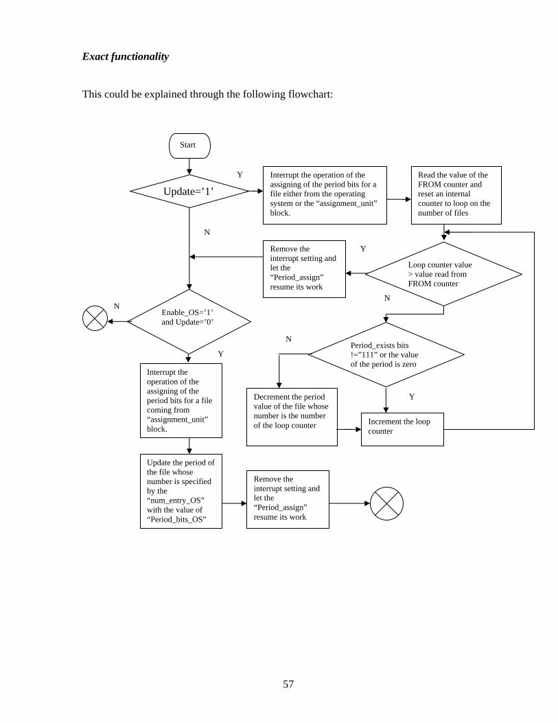
Exact functionality
This could be explained through the following flowchart:
Start
Y
Interrupt the operation of the assigning of the period bits for a file either from the operating system or the “assignment_unit” block.
Update=’1’ Read the value of the FROM counter and reset an internal counter to loop on the number of files
Period_exists bits !=”111” or the value of the period is zero
Increment the loop counter
Decrement the period value of the file whose number is the number of the loop counter
Remove the interrupt setting and let the “Period_assign” resume its work
Y
Y
N
N
Loop counter value > value read from FROM counter
Enable_OS=’1’ and Update=’0’
N
Interrupt the operation of the assigning of the period bits for a file coming from “assignment_unit” block.
Update the period of the file whose number is specified by the “num_entry_OS” with the value of “Period_bits_OS”
Remove the interrupt setting and let the “Period_assign” resume its work
Y
N
57

Reset=’1’ set “Enable_WB” to zero and reset the operation of the block
Enable_assign=’1’ and update=’0’ and enable_os=’0’
Save the period bits to the file number specified by the “num_entry” signal
Set the “enable_wb” to ‘1’ Start
N
N
Y
Y
Fig. 18: The “Period_Assign” Flowchart
58

3.3.2.4 “Write_buffer” block
Main job
This block formats the header that is saved with the file after the license assignment
procedure is done to be able to retrieve the information about that file.
Block diagram
Write_Buffer Block
Num_entry
Ack_OS
Address_t_ram (8 bits)
Clk_ram
We_ram_w
Address_t_ram_w(8 bits)
Data_t_ram_w(8 bits)
Clk Reset
Enable_SSU
Assign_finish
Read_ram
clk_ram_w
Data_f_ram(8 bits)
Fig. 19: The “Write_Buffer” Block Diagram
59

Pins description
- Num_entry: This is the signal sent by the “assignment_unit” which specifies the
number given by the DRU to reference that file.
- Enable_SSU: This is the enable signal sent by the “period_assign” block.
- Assign_Finish: This is the signal by which the “write_buffer” indicates to the operating
system that the file’s header , which will be saved with it, is created and saved in the
location specified by the operating system before the start of the assigning procedure.
- Ack_OS: This is the acknowledgment signal from the operating system side to the
“Assign_Finish” signal.
- Address_t_ram: These are the address lines used to access a certain location of the
memory which contains the original file’s header (The header of the file that exists with
the file when it was sent by the provider’s server). This memory is called the header
memory as explained previously during our talk about the “check_userIDs” block.
- Data_f_Ram: This is the bus from which the data saved in the header memory is read.
- Read_ram: This is the signal used to indicate the read operation from the header
memory.
- Clk_ram: This is the clock signal used to interact with the header memory.
- we_ram_w: This signal is connected to the write enable signal of the memory where
the assigned header for the file is written. We will call that memory location
“write_buffer memory”.
- Clk_ram_w: This is the signal connected to the clock signal of the write_buffer
memory.
- Data_t_ram_w: These are the assigned header bits to be saved in the write_buffer
memory.
- Address_t_ram_w: These are the address bits used to save the assigned header bits at a
certain location in the write buffer memory.
- Clk: These are the internal clock pulses which are generated independently of the
system clock signal.
- Reset: This signal is used to reset the operation of the “write_buffer” block
60

Note that:
- The tag “ram” ,existing within the signal names with interacting the write_buffer
memory, is used to indicate the random access functionality not the volatile feature of
the RAM memories.
- The “SSU” tag found in the enable signal stands for “Security setting unit”. Since the
inputs for the “write_buffer” comes from the “assignment_unit” and the
“period_assign” blocks which both are the parts that ensure the security of the media
file, we choose the name of the enable signal to be “enable_SSU”
61

Exact functionality
The “write_buffer” functionality could be explained through the following flowchart:
Start
Reset=’1’ set “Assign_finish” to zero and reset the operation of the block
Access the header memory to get the company IP bits
Write in the “write_buffer” memory the company IP bits and the “num_entry” value of the file.
Y
Y
N
N
Set “Assign_finish” signal to ‘1’
Ack_os=’1’
End
Y
N
Enable_SSU =’1’
Fig. 20: The “Write_Buffer” Flowchart
62

3.3.3 LCU architecture The main blocks of the LCU are shown in figure 21:
File check Recheck block
Period check
Signals exchanged with the OS and the memory containing the header of the file
Enable signal
Signals exchanged with the OS and the memory where the recheck data is written
Enable signal Signals exchanged with the OS
Fig. 21: The LCU Architecture As shown in figure 21, the three main blocks of the LCU are:
1- File check: This unit is used to check on the header attached to the file.
2- Recheck block: this part is responsible for handling the task of rechecking the file
when the DRU can’t find a license for that file.
3- Period check: It checks on the period assigned to the file the user wants to access
63

3.3.3.1 “File_check”
Main job
This unit checks the address attached to the file which the user wants to access to find out if
the file has any license information or not.
Block diagram
File_check Block
Deactivate
Enable_decision
Continue
clk_FROM
q_FROM(8 bits)
Read_FROM
Address_t_ram(5 bits)
Clk Reset
Deactivate_Ack
Read_ram
clk_ram
Check_req
Data_f_ram(8 bits) Enable_OS_check
Enable_Recheck
Enable_period_check
Address_t_period
read_ram_license
Address_license (8 bits)
Data_f_ram_license(40 bits)
clk_ram_license
License_info(40 bits)
Fig. 22: The “File_Check” Block Diagram
64

Pins description
- Deactivate: Through this signal, the “file_check” block sends its request to the
operating system to deactivate some interrupts and IO operations to provide a secure
path between DRU and the external components like RAM.
- Deactivate_ack: This signal which is set by the operating system as a reply to the
“Deactivate” request.
- Enable_decision: This is the enable signal sent by the “Decision_block”.
- Enable_OS_check: This is the signal used to indicate to the operating system to start
the execution of the license file whose space and location are specified by the
“license_info” bits.
- License_info: These are the license information bits saved in the internal license
memory of the DRU for the file whose number is specified in the file’s header. The
format of these bits was explained previously during the talk about the
“assignment_unit” block.
- Continue: This signal is high if the integrity checks embedded in the license file
returned correct results. This means that this is a valid license file for the file under
check and the “file_check” block should enable the “period_check” block to test if the
license’s period is not expired.
- Check_request: This signal is high if the integrity checks embedded in the license file
returned wrong results. This means that the “file_check” needs to access the
“recheck_block” to review the media file’s license with the provider’s server.
- Enable_Recheck: This is the enable signal sent to the “recheck_block”.
- Enable_Period_check: This is the signal connected to the enable signal of the
“Period_check” block.
- Address_to_period: This is the number of the file found in the file’s header and which
is sent to the “Period_check” block to check on this file’s number license’s period.
- Clk_FROM: This is the signal connected to the clock signal of the internal FROM
counter.
- q_FROM: These are the bits read from the internal counter FROM of the DRU.
- read_FROM: This signal is connected to the read enable signal of the FROM counter.
- Address_t_ram: These are the address bits used to access a certain location in the
memory where the header of the file, the “header recheck memory”, is loaded by the
65

operating system. As explained previously, the “header recheck memory” is a memory
location reserved by the operating system in which the operating system moves the
file’s header.
- Data_f_Ram: This is the bus from which the data saved in the “header recheck
memory” is read.
- Read_ram: This is the signal used to indicate the read operation from the “header
recheck memory”.
- Clk_ram: This is the clock signal used to interact with the “header recheck memory”
- read_ram_license: This signal is connected to the read enable signal of the internal
license memory of the DRU.
- Clk_ram_license: This is the signal connected to the clock signal of the internal license
memory.
- Data_f_ram_license: These are the license info bits read from the internal license
memory.
- Address_license: These are the address bits used to read the license info bits at a certain
location in the internal license memory. The value of these bits is received from the file
number saved in the file’s header.
- Clk: These are the internal clock pulses which are generated independently of the
system clock signal.
- Reset: This signal is used to reset the operation of the “file_check” block
Note that:
- The file header referenced here is the header created by the “write_buffer” block when
the file was assigned not the header which was sent with the file during the assignment.
Exact functionality
With the following flowchart, we can summarize the flow of operations within the
“file_check” block:
66

Start
Reset=’1’ set “Enable_period_check” , “Enable_recheck” and “Enable_OS_check” to zero and reset the operation of the block
Set “Deactivate” signal to ‘1’
Access the header recheck memory to get the number of the file.
Access the internal counter FROM to get the number of files so far assigned by the DRU
FROM counter value<number assigned to the file
Access the internal license memory to get the license information bits assigned to the specified line number
End
Y
Y
N
N
Y
N
N Y
Set “Enable_recheck” signal to ‘1’
Set “Enable_OS_check” signal to ‘1’
Continue=’1’
Recheck_request =’1’
End
Set “Enable_recheck” signal to ‘1’
Set “Enable_period_check” signal to ‘1’
Y
Y N
N
Deactivate_ack =’1’
Enable_Decision =’1’
Fig. 23: The “File_Check” Flowchart
67

3.3.3.2 “Recheck_unit”
Main job
It handles the task of rechecking the file when the DRU can’t find a license for that file.
Block diagram
Recheck_unit Block
Enable_FCB
Ack_OS
Address t ram(5 bits)
Clk Reset
Read_ram
clk_ram New_sequence
Data_f_ram(8 bits)
EOJ_OS
End_required_seq
We_t_HC
Address_t_HC (5 bits)
Data_t_HC(8 bits)
clk_t_HC
Sequence_needed
End_seq_OS
Ack_OS_seq
We_seq
Address_seq (8 bits)
Value_seq(8 bits)
clk_seq
Address_t_PROM (4 bits)
Read_PROM
Data_f_PROM (8 bits)
Clk_PROM
Fig. 24: The “Recheck_Unit” Block Diagram
68

Pins description
- Enable_FCB: This is the enable signal sent by the “file_check” unit
- EOJ_OS: Through this signal the “recheck_block” indicates to the operating system
that it has finished its normal job of writing the information needed to be sent to the
provider’s server in the memory location specified by the operating system. This
memory space is called “Header compliance memory”
- Ack_OS: This is the acknowledgement signal to the “EOJ_OS”. This signal is set when
the operating system has sent the information written by the “recheck_block” to the
provider’s server.
- New_Sequence: The operating system sets this signal high when there’s a request from
the provider’s side for certain parts of the file to be sent.
- Sequence_needed: This is the number of the requested KB part of the file to be sent.
- End_seq_OS: This is the signal which is set high by the operating system when the
provider’s server finishes sending its parts request.
- End_required_seq: By this signal, the “recheck_block” informs the operating system
that it has finished its writing operations in the memory location set by the operating
system before sending the “New_sequence” request. This memory location was set so
that the “recheck_block” registers in it the number of the parts requested. This memory
is called “sequence memory”.
- Ack_OS_seq: When the operating system has read all the required parts written by the
“recheck_block” in the special memory space, the operating system indicates this to the
“recheck_block” through this signal.
- Address_t_ram: These are the address bits used to access a certain location in the
memory where the header of the file, the “header recheck memory”, is loaded by the
operating system. As explained previously, the “header recheck memory” is a memory
location reserved by the operating system in which the operating system moves the
file’s header.
- Data_f_Ram: This is the bus from which the data saved in the header recheck memory
is read.
- Read_ram: This is the signal used to indicate the read operation from the header
recheck memory.
69

- Clk_ram: This is the clock signal used to interact with the “header recheck memory”
- we_t_HC: This signal is connected to the write enable signal of the Header Compliance
memory.
- Clk_t_HC: This is the signal connected to the clock signal of the Header Compliance
memory.
- Address_t_HC: These are the address bits used to write the header bits that will be sent
to the provider server in the Header Compliance memory.
- Data_t_HC: These are the header bits that will be sent to the provider’s server.
- we_seq: This signal is connected to the write enable signal of the sequence memory.
- Clk_seq: This is the signal connected to the clock signal of the sequence memory.
- Address_seq: These are the address bits used to write the requested file parts numbers
in the sequence memory.
- Value_seq: This is the requested file part number. The value of that signal is got from
the “sequence_needed” value.
- Address_t_PROM: These are the address lines connected to the address bits of the
internal PROM memory of the DRU which contains the user and group IDs bits chosen
by the user at the setup of the DRU for the first time.
- Data_f_PROM: This is the bus from which the data saved in the PROM memory is
read.
- Read_PROM: This signal is connected to the read enable signal of PROM memory .
- Clk_PROM: This is the clock signal used to interact with the PROM memory.
- Clk: These are the internal clock pulses which are generated independently of the
system clock signal.
- Reset: This signal is used to reset the operation of the “recheck_unit” block.
Note that:
- The operating system will identify that the received request from the provider’s server is
either to “initialize the sequence request” or to “end the sequence request” or to “request
for a certain part number of the file” through special format sent by the provider and
understood by the operating system.
70

Exact functionality
Through the following flowchart, the functionality of the recheck unit could be explained:
Start
Reset=’1’ set the “EOJ_OS” and “end_required_seq” to zero and reset the operation of the block
Y
N
New_sequence=’1’
Access the sequence memory to save the requested file numbers
End_seq_OS =’1’
Reset all the signals used in the communication with the sequence memory
Interrupt the normal file checking operations
Set the “end_requiresd_seq” high and the operating system starts reading the numbers saved in the sequence memory
Ack_OS_seq =’1’
Disable the interrupt request
Enable_FCB=’1’ and New sequence=’0’
Access the header recheck memory to get the company IP bits
Access the internal PROM memory to get the user and group IP bits
Format the header that will be sent to the provider’s server and save it in the Header Compliance memory
Set the “EOJ_OS” signal high
Ack_OS =’1’
Start
Y
Y
Y
Y
Y
N
N
N
N
Fig. 25: The “Recheck_Block” Flowchart
71

3.3.3.3 “Period_check”
Main job
This block is responsible for checking on the period assigned to the file the user wants to
access
Block diagram
Period_check Block
Enable_FCB
Ack_OS
Address_Pram (8 bits)
Clk_Pram
Clk Reset
Address_f_FCB
GRANT
Read_Pram
q_Pram(8 bits)
Update_ON
Update_OS_ON
Delete
Fig. 26: The “Period_Check” Block Diagram
72

Pins description
- Enable_FCB: This is the enable signal sent by the “file_check” block.
- Address_f_FCB: This is the number of file that was got by the “file_check” block from
the file’s header and passed to the “Period_check” block.
- Update_ON: This is the signal sent by the “Period_Assign” block which indicates that
the daily update process is in progress.
- Update_OS_ON: This signal sent by the “Period_Assign” block which is used to
indicate the an update process based on the operating system request is in progress.
- Grant : This signal ,when set high by the “Period_check” block, indicates to the
operating system that the license period did not expire.
- Delete: Through this signal the “Period_check” block indicates to the operating system
that the assigned period for the file is expired. Accordingly, the operating system will
delete the file or prompt the user to recontact the provider to get a new license.
- Ack_OS: This is the acknowledgement signal sent by the operating system for the
“Delete” or “Grant” signal.
- q_Pram: These are the bits read from the internal period memory.
- read_Pram: This signal is connected to the read enable signal of the internal period
memory.
- Clk_Pram: This is the signal connected to the clock signal of the internal period
memory.
- Address_Pram: These are the address bits used to read the period bits at a certain
location in the internal period memory. The value of the “address_Pram” is the value of
“address_f_FCB” signal explained above
- Clk: These are the internal clock pulses which are generated independently of the
system clock signal.
- Reset: This signal is used to reset the operation of the “Period_check” block
73

Exact functionality
This could be summarized by the following flowchart:
Start
Reset=’1’ set “GRANT” and “DELETE” to zero and reset the operation of the block
Y
N
Update_ON=’1’ or update_OS_ON=’1’
Access the internal period memory to get the period bits for the file whose address is the value of the “address_f_FCB”
Period_exist bits=’111’ and period value=0
Set “Delete” signal to ‘1’
Set “Grant” signal to ‘1’
Ack_OS=’1’
End
Y
Y
N
N
N
Y
Fig. 27: The “Period_Check” Flowchart
74

3.4 Requirements from other parts to complete the DRU job
In order to have a complete DRM solution, some parts involved in the system should provide
some services to support the functionalities of the DRU unit.
We list the requirements of each of these parts separately as follows:
3.4.1 The operating system
Here is the list of requirements that the operating system(OS) should provide:
1- All the transactions with the DRU should be implemented on the Kernel level to
prevent any other software to connect with the DRU. Accordingly, the security
settings offered by the operating system depend on securing its kernel from being
modified or replaced. To do this, the proposed operating system should include a tool
like Kernel Patch Protection (KPP) also known as Patch Guard introduced by
Microsoft in their products. This tool performs the required protection task through
monitoring the Kernel’s key resources like system service tables and if it finds any
modifications it shuts down the system [39]. This, in the existence of processor
structures like Intel x86 ring structure which define privilege levels of software
execution, can provide the desired kernel protection.
2- The OS should be able to encrypt and decrypt file parts or messages exchanged with
the provider’s server. If the encryption/decryption operation is handled by a hardware
engine, the OS kernel should exclusively deal with this hardware engine.
3- The OS should handle the network and communication protocols used during the send
and receive operations to and from the provider’s server.
4- It should contain a driver which can interface properly with the DRU signals such as
“DEACTIVATE” ,“DEACTIVATE_ACK”,”DELETE” and ”RESET”. Also, the
driver should contain a time-out software to take action if there’s a problem in
communication either with the provider’s server during the rechecking procedure or
with other parts of the system.
75

5- It should be able to reserve and secure some parts of the memory during the
transactions with the DRU as for example reserving a memory location which
contains the file during the reception of the file parts.
6- It should protect the file from being tampered with during the checking of the file by
the DRU and after receiving a grant signal to access it. An example of the possible
tampering attempts is to access a file with outdated license by using the grant signal of
another file.
7- The OS should automatically deactivate the interrupts when there’s a sequence
request from the provider’s server during the recheck procedure before the operation
of the DRU.
8- It should understand and execute the license file written in a rights expression
language supported by this DRU and communicate with the DRU in case of any
updates such as updating the period of a file. In case the used language is other than
the MPEG-REL or the ODRL, it should be able to execute the software patch sent
with the license file.
9- The operating system should also reserve and protect the memory location defined by
the user during the setup of the DRU which will contain the license files.
3.4.2 Synchronization circuit
Due to the fact that our system is working on an independent clock signal, we need a
synchronization circuitry in order to properly interface it with the user’s system.
We will use two main kinds of synchronization circuits [19]:
1- Synchronizer using dual-stage flip-flops
Fig. 28: The Dual-Stage Flip-Flop Synchronizer
D Q D Q D Q Data In Data Out
FF1 FF2
CLK1 CLK2
76

The reason for using two flip flops FF1 and FF2 at the system clock side is to solve the case if
FF1 goes meta-stable with clock signal clk2, by that FF2 does not look at data until a clock
period later, giving FF1 time to stabilize.
This synchronizer will be used to interface single bit signals like “WRITE”, “READ” signals
2- Synchronizer using asynchronous FIFO.
This synchronizer will be used to interface multi-bit signals such as the address lines
connected to the memory. The architecture of this synchronizer looks like the following
figure:
Fig. 29: Synchronizer Using Asynchronous FIFO We couldn’t use the synchronizer with simple dual-stage flip-flops because we can’t
guarantee that all the bits of the signal would arrive at the same time together.
The main problem with the asynchronous FIFO design shown in figure 29 is the
implementation of the empty and full signals. This is because the write circuit should be able
to read the read pointer and vice versa which have different clocks. The suggested solution
for that issue is to implement the read and write pointers as gray coded values to eliminate the
problem that could occur if any of the pointer changes its position while the other is reading
its value.
77

3.4.3 The provider’s server
1- The server at the provider side should have for each user an entry as shown in figure:
User Password
Sequences to generate key
File Name User ID Group ID License info Key generated
Fig. 30: Entry at the provider’s server
Also, the provider’s server should have the capability to search and check on these fields
when there is a recheck request sent by the user’s DRU.
2- When sending its sequence request, the provider’s server should have a bit always set high
which will be interfaced to the “new_sequence” bit of the DRU. This bit will be set to zero
when the sequence request ends.
3- The provider should have the bug free software patches that translate a license file rules
written with any other language than MPEG21-REL or ODRL to MPEG21-REL.
78

Chapter IV Simulation Results In this chapter we show the simulation results of the DRU unit after implementing its
functionalities in VHDL. These simulation results are obtained using Modelsim tool of
Mentor Graphics [23].
In section 4.1, we discuss the results of each of the LAU blocks separately.
In section 4.2, the results for the LCU blocks are shown.
For each of these blocks we show the normal operating condition and special cases to show
the different implemented features of the block.
In section 4.3, the simulation results for the blocks that are not part of the LAU or the LCU
like the decision block are listed.
4.1 LAU simulation results
4.1.1 “Check_userIDs” simulation results
a- Normal case
This is the normal operating condition that was discussed through the flowchart in section
3.3.2.1
Fig. 31: The Normal Operation Of “Check_UserIDs”(1st part)
79

As seen in figure 30, the reset signal is set high first to initialize all the internal operations.
Then the “Deactivate” signal is set to’1’ .When the “Deactivate_ack” reply is received the
operation of the “check_userIDs” starts by getting the IDs sent with the file which exist in a
specific memory location where the header of the file is saved through the signals
“address_t_ram”, “read_ram” and “data_f_ram”.
After that, the IDs that are saved in the internal PROM of the DRU are compared versus those
got from the header of the file as shown in figure 31.
Fig. 32: The Normal Operation Of “Check_UserIDs”(2nd part)
If the two are the same, as is the case in the above figure, the “Enable_rest” signal is set high
and the “delete” signal is set to ‘0’.
Note that the “Enable_rest” signal is high for only four clock cycles to reduce the amount of
dissipated power.
b- “No_enable” case
This is the case where we show the effect of the Enable signal from the “Decision_block”.
Fig. 33 : The “No_Enable” Case For The “Check_UserIDs”
80

As it can be seen here, since there’s no enable signal received from the decision block, no
operation was performed by the “check_userIDs” block.
c- “No_Deactivate_Ack” case
Here we are showing that the whole operation of the “check_userIDs” block holds until the
“Deactivate_ack” signal is received.
Fig. 34 : The “No_Deactivate_Ack” Case For The “Check_UserIDs” The time out software of the operating system is responsible for indicating the failure of the
deactivate operation and resetting the “check_userIDs” block if after a certain period of time
there is no “Deactivate_ack” pulse received.
d- “Different_userIDs” case
This part is to show the response of the “check_userIDs” block when different user and/or
group IDs are found in the header of the file.
Fig. 35: The “Different_UserIDs” Case Of The “Check_UserIDs”
81

As shown in figure 34, although the header of the file under assignment has the same group
ID as that saved in the internal PROM of the DRU, the delete signal is set high because the
user ID bits are not the same.
e- “reset” case
In this case, we can see that whenever the reset signal occurs, all the operations of the
“check_userIDs” block stop and start all over again from the beginning.
Fig. 36: The ”Reset” Case For The “Check_UserIDs”
82

4.1.2 “Assignment_unit” simulation results
a- Normal case
This is the normal operating condition for the assignment unit.
The functionality of this case was discussed in details in section 3.3.2.2
Fig. 37 : The Normal Operation Of The “Assignment_Unit”
As shown in figure 36, first the reset signal is set to initialize the assignment unit’s different
operation. Then, if the enable signal from the “check_userIDs” block is received through the
“enable_check_user” signal, the internal FROM counter of the DRU, which holds the number
of files so far assigned by the DRU, is read to ensure that the DRU internal memory is not yet
full. After reading the value the internal FROM counter value is automatically incremented.
This is shown through the signal “q_FROM”, which holds the value of DRU internal counter
before assignment, and the signal “data_FROM” which holds the value of the counter after
the increment.
After that, the license user’s bits are checked to be sure that there’s a valid license attached
with the file. The DRU then sets the “space_request” signal high to ask the operating system
to provide for it a space with the “XML_size” value in the special curtained memory region
where the license files are held.
When the acknowledgement is received from the operating system through the
“space_available”signal, the assignment unit saves in the internal license memory of the DRU
the address sent by the operating system where the new license file is saved attached with it
the size of the license file.
83

Finally, the assignment unit sends the following signals to the “period_assign” block:
1- The enable signal for the period circuit through the “enable_clk_circuitry” signal
2- The address assigned by the assignment unit to that file through the “num_entry”
signal. This address value is the current value of the DRU internal counter.
3- The period bits that exist in the header of the file through the “period_bits” signal.
b- “No_enable” case
This is the case which shows that the assignment unit work holds until the enable signal from
the “check_userIDs” block is received.
Fig. 38 : The “No_enable” Case For The “Assignment_Unit” c-“No_space_available” case
In this case we are discussing what happens if the operating system couldn’t allocate a space
in the curtained memory of the license files for the new file
Fig. 39: The “No_Space_Available” Case For the “Assignment_Unit”
84

As seen in figure 38, the enable signal to the period circuitry is not set waiting for the
“space_available” signal to be set high in reply for the “space_request” signal sent earlier by
the assignment unit.
The time out software of the operating system is responsible for indicating the failure of the
operation of reserving a memory location in the curtained memory space and resetting the
“Assignment_unit” block. This occurs if after a certain period of time there is no
“space_available” pulse received.
d- “No_space_FROM” case
Through this case we want to show what happens if the memory of the DRU is already full
when assigning a new file. The number of files assigned already by the DRU is used to
identify if the DRU’s internal memory is full or not.
In our case, the DRU design can assign up to 256 files.
Fig. 40: The “No_Space_FROM” Case Of The “Assignment_Unit” As seen in figure 39, when the signal “limit_FROM” is high this means that the DRU’s
internal memory is full. In that case, the assignment unit sets the “delete” signal high to let
the operating system prompt the user for the delete action it’s going to execute.
85

4.1.3 “Period_assign” simulation results
a- Normal case
This is the normal operating condition for the “period_assign”.
Fig. 41: The Normal Operation Of The “Period_Assign” As seen through figure 40, the “reset” signal is first set high to initialize the jobs of the
“Period_assign”. Then, if the enable signal from the assignment unit “enable_assign” is high
and there is no update operation request either from the operating system or the clock update
signal, the internal memory of the DRU which holds the period of the files is accessed to save
the period bits.
The address for that memory is the “num_entry” signal sent by the assignment unit.
At the end of its job, the “Period_assign” enables the “write_buffer” block through the signal
“Enable_wb”.
b- “Update_OS” case
Here we show what happens when the operating system needs to update the period of a
certain file. This could occur during the recheck operation, if the operating system needs to
update the period assigned to a certain file after parsing and executing its license file.
Fig. 42: The “Update_OS” Case For The “Period_Assign”
86

As seen in figure 41, when the operating system needs to update a period, the operating
system sets the signal “enable_OS” high. It then provides the number of the file it wants to
update through the signal “num_entry_os” and the new value for the period which is the
value of the “Period_OS” signal.
Accordingly, the “Period_assign” updates that memory location with the address value as that
of the “num_entry_OS” with the new period value.
c- “Normal_update” case
In this case, we discuss the update process initialized by the update signal from the clock
circuitry.
Fig. 43 : The “Normal_Update” Case For The “Period_Assign”
What exactly happens during the update process could be explained as follows:
1- After the “update” signal is set high, the Period block accesses the DRU FROM
counter to know the number of files whose period should be updated.
2- Then, for each file, the period existence bits are checked. If these bits are set to the
value “111”, then this means that this period has a certain period assigned for it and
accordingly the “Period_assign” decrements the value of the period bits if it is not
already all zeros. But if the period existence bits are set to different value from “111”,
then this means that this license has unlimited period and so the “Period_assign” does
not update this entry.
87

d-“Update_OS_while_normal_update” cases
In this section, we show the case when an update request from the operating system occurs
while the normal update process is not yet finished.
Fig. 44: The “Update_OS_While_Normal_Update” Case For The “Period_Assign” As seen through figure 43, when the “Enable_OS” signal is received while the normal update
operation is in action, the value of the “Period_OS” and the “num_entry_OS” will be saved
such that when the normal update process is finished, the period of the specified file is
updated according to the value of the “period_OS”.
e-“Enable_assign_while update” case
In this section, we show the case when there is a request to assign a period to a new file while
the normal update process is not yet finished.
Fig. 45: The “Enable_Assign_While_Update” Case For The “Period_Assign”
88

As seen through figure 44, the operation of assigning the period for a new file has lower
priority than the update process. This means that the period assignment process is held while
the normal update functionality is on.
f-“Enable_OS_and_enable_assign” case
In this section, we show the case when an update from the operating system occurs when the
period assignment process is also started.
Fig. 46: The “Enable_OS_And_Enable_Assign” Case For The “Period_Assign” When the “Enable_OS” signal is received with the “Enable_assign” signal, the update request
is recorded so that when the assignment process is finished, the required operating system
update is applied. This means that period assignment functionality has a higher priority than
the operating system update process.
g-“Reset” case
In this section, we discuss the effect of the rest signal on the period assignment procedure
Fig. 47: The “Reset” Case For The “Period_Assign”
89

As shown in figure 46, when the reset signal is high the whole period assignment
functionality is restarted from the beginning.
h-“Reset_with_Enable_OS” case
Here, the reset signal effect on the operating system update process is discussed.
Fig. 48:The “Reset_With_Enable_OS” Case For The “Period_Assign” As seen in figure 47, when the reset signal is high, the operating system update process is
stopped and reset. Also, it shown in the above figure that the reset procedure has a higher
priority than the operating system functionality.
i-“Reset_with_update” case
In this case, the relation between the reset procedure and the normal update process is shown.
Fig. 49: The “Reset_With_Update” Case For The “Period_Assign” As seen in figure 48, the reset signal has no effect on the normal update functionality. This is
because the normal update operation is an operation that is only handled by the DRU and
need nothing from the operating system to continue its job.
90

4.1.4 “Write_buffer” simulation results
a-Normal case
This is the case which explains the normal operation of the “write_buffer” block.
Fig. 50 : The Normal Operation Of The “Write_Buffer” As seen in figure 49, the “reset” signal is first set high to initialize all the signals involved in
the operation of the “write_buffer”.
Then, when the enable signal from the “Period_check” block, “enable_ssu”, is received, the
“write_buffer” accesses the memory location where the header of the file was saved to get the
company IP bits.
These bits are then written in the memory space reserved for the creation of the header which
is attached to the media file when stored after the license assignment procedure is finished.
After that, the “write_buffer” adds the number assigned by the DRU for that file to the
created header which is the “num_entry” value.
At the end of its operation, the “write_buffer” indicates the end of its job by setting the signal
“assign_finish” high and waits for the acknowledgement from the operating system which is
observed through the “ack_OS” signal.
The time out software of the operating system is responsible of indicating the failure of the
operation of saving the header created to the file and resetting the “write_buffer” block. This
happens if after a certain period of time there is no “ack_OS” pulse received.
91

b-“Reset” case
In this case, we are showing the effect of the “reset” signal on the operation of the
“write_buffer” block.
Fig. 51: The “Reset” Case For The “Write_Buffer” As observed in figure 50, when the “reset” signal is set high the operation of the
“write_buffer” unit, which was started previously by the “enable_ssu” signal, is stopped and
returned to its initial state where the “write_buffer” is waiting for the “enable_ssu” to be set
high.
92

4.2 LCU simulation results
4.2.1 “file_check” simulation results
a-Normal case
The normal operating condition for the “file_check” block is discussed here.
Fig. 52: The Normal Operation Of The “File_Check”
The functionality shown in figure 51 can be explained as follows:
- The “reset” signal is first set high to initialize the different parts of the “file_check”
block.
- If the “enable” signal , which is the enable signal from the “Decision_block”, is high
then the “file_check” block sends a “deactivate” signal for the operating system to
deactivate interrupts and I/O operations.
- When the acknowledgement from the operating system is received through the signal
“deactivate_ack”, the “file_check” accesses the memory where the header of the file
is saved to get the number of the file which is received through the signal
“data_f_ram”.
- Then, the “file_check” unit accesses the internal FROM counter of the DRU,
whose value is held by the signal “q_from”, to check that the number assigned to the
93

file is within the range of the number of files assigned by this DRU or not. If not, then
the “recheck_block” is invoked to let the provider checks on that file.
In our case the number of the file is “2”, according to the value of “data_f_Ram” signal and
the value of the internal FROM counter is “4” and so the file is in range. The next step is to
provide the operating system with the information about the license file assigned to that file
number.
This is done through that “file_check” accesses the internal memory of DRU which holds the
license files information. Then, it sends an enable signal to the operating system,
“enable_OS_check” signal, along with the license information which is read by the operating
system through the signal “license_info”.
Then the flow of the normal operation continues as follows:
- The operating system sets high either the “Continue” signal , in case the integrity
checks included in the license file run successfully, or the “Enable_recheck” signal in
case of wrong results produced from the integrity check. In our case, we assume that
“Continue” signal is set high.
- Accordingly, the “file_check” sends an enable signal to the “period_check” block
through the signal “Enable_period_check” to test the period assigned to the file under
check. Also, the “file_check” sets the value of the “address_to_period” to the number
assigned to that file.
94

b-“address_out_range” case
Here, we show what happens when the number assigned to the file is out of the range of the
number of files assigned by the DRU. This could happen for example if the file is copied
from another place where another DRU holds the license file of that file.
Fig. 53: The “Address_Out_Range” Case Of The “File_Check” In our case here, the number of files assigned by this DRU is “1” but the address saved within
the file header is “2”.
By consequence, the “Enable_recheck” is set high to check on this file license with the
provider.
c-“No_Deactivate_Ack” case
In this section, we show what happens when the signal “Deactivate_ack” sent by the
operating system to confirm that the “Deactivate” request is granted.
Fig. 54: The “No_Deactivate_Ack” Case For The “File_Check”
95

As seen in figure 53, when the “Deactivate_ack” signal is not received, the whole operation
of the “file_check” unit is held. The time out software of the operating system is responsible
of indicating the failure of deactivating the interrupts and resetting the “file_check” block.
This happens if after a certain period of time there is no “Deactivate_ack” pulse received.
d-“Reset” case
In this case, the effect of the reset signal on the operation of the “file_check” unit.
Fig. 55: The “Reset” Case For The “File_Check” As shown in figure 54, when the reset signal is high, the operation of the “file_check” unit is
stopped and restarted from the beginning.
96

4.2.2 “recheck_block” simulation results
a- Normal case
In this section we discuss the normal operation flow of work in the “recheck_block”
Fig. 56 : The “Normal Case” For The “Recheck_Block” After the “reset” signal initialized the different parts of the “recheck_block”, the memory
which contains the header of the file is accessed to get the company IP bits which are
received through the signal “data_f_ram”.
Then, the PROM of the DRU is accessed to get the user and group ID bits.
At the end of its job, the “recheck_block” indicates to the operating system to send the
required recheck information saved in the memory location reserved by the operating system
before the start of the “recheck_block” operation to the provider. This is done through setting
the signal “eoj_OS” high.
The “recheck_block” then waits for the acknowledgment from the operating system that
should be asserted through the signal “Ack_OS”.
The time out software of the operating system is responsible of indicating the failure of the
reading and sending the saved header to the provider and resetting the “recheck_block”
operation. This happens if after a certain period of time there is no “ack_OS” pulse received.
97

b- “New_Sequence” case
This is the case where we discuss the effect of the “new_sequence” signal.
As explained previously, the “new_sequence” signal is used by the operating system to
indicate to the “recheck_block” that a provider is sending a request for certain parts (or
sequences) of the file to check on them.
Again, the “recheck_block” is invoked in that operation to speed up the operation of
rechecking process and also for the target that this procedure will be completely handled by
the “recheck_block” in the future.
Fig. 57: The “New_Sequence” Case For The “Recheck_Block” As seen in figure 56, when the “new_sequence” signal is received, the data sent by the
provider “sequence_needed” is automatically sent to the memory location reserved by the
operating system for the “recheck_block”.
The numbers here of the sequence required refers to the number of Kbytes of the file.
In other words, the number “72” means that the provider’s server is requesting that the Kilo
byte number 72 of the file to be sent to check.
At the end of the sequences’ request, the signal “end_seq_OS” is sent to the “Recheck_block”
so that it disables the write enable signal “we_seq”. After that, the “recheck_block” requests
the acknowledgment from the operating system after it finishes reading the data through the
signal “end_required_seq”.
The “recheck_block” then waits until the operating system acknowledgment is received
through the signal “ack_os_seq”.
98

The time out software of the operating system is responsible for indicating the failure of
reading the saved sequences and restarting the recheck procedure from the beginning by
requesting the sequences once again. This happens if after a certain period of time there is no
“ack_OS_seq” pulse received.
c-“new_sequence_while_normal” case
Here, we discuss what happens when there’s a sequence reply for a certain file from the
provider’s server while there’s a request for another file to be checked.
Fig. 58 : The “New_Sequence_Enable” Case For The “Recheck_Block” When the “new_sequence” request is detected, the normal recheck operation is held, as could
be seen in figure 57, through the “address_t_hc” signal which is the address through which
the recheck header data is saved.
When the “ack_os_seq” signal is set high, the normal recheck operation is resumed.
d-“Reset” case
In this case, we discuss the effect of the reset signal on the operation of the recheck block.
Fig. 59 : The “Reset” Case For The “Recheck_Block”
99

When the “reset” request is detected, the normal recheck operation is stopped and restarted
from the beginning by retrieving the file’s company IP saved in the memory containing the
header of the file.
d-“Reset_new_sequence” case
Here, we discuss the effect of the reset signal when it is received when there’s a sequence
reply for a certain file from the provider’s server.
Fig. 60 : The “Reset_New_Sequence” Case For The “Recheck_Block”
As shown in figure 59, when the reset signal is received, the operation of saving the required
sequence of the file is stopped. This is because when the reset signal is high, this means that
there is a security issue. An example of these security issues is that if a software is trying to
access the memory locations where the required sequences are saved.
It is the responsibility of the operating system to request again the needed sequence of the file
from the provider when this case happens.
100
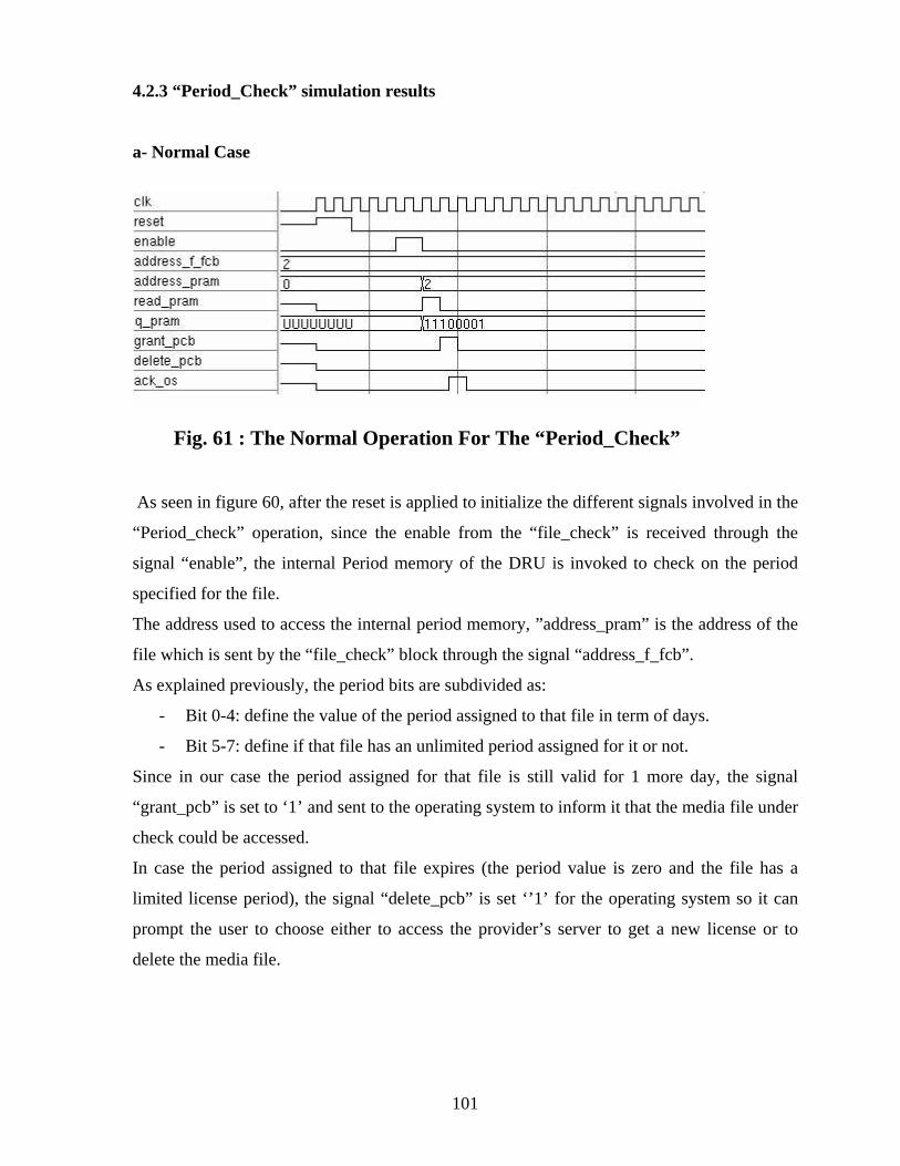
4.2.3 “Period_Check” simulation results
a- Normal Case
Fig. 61 : The Normal Operation For The “Period_Check”
As seen in figure 60, after the reset is applied to initialize the different signals involved in the
“Period_check” operation, since the enable from the “file_check” is received through the
signal “enable”, the internal Period memory of the DRU is invoked to check on the period
specified for the file.
The address used to access the internal period memory, ”address_pram” is the address of the
file which is sent by the “file_check” block through the signal “address_f_fcb”.
As explained previously, the period bits are subdivided as:
- Bit 0-4: define the value of the period assigned to that file in term of days.
- Bit 5-7: define if that file has an unlimited period assigned for it or not.
Since in our case the period assigned for that file is still valid for 1 more day, the signal
“grant_pcb” is set to ‘1’ and sent to the operating system to inform it that the media file under
check could be accessed.
In case the period assigned to that file expires (the period value is zero and the file has a
limited license period), the signal “delete_pcb” is set ‘’1’ for the operating system so it can
prompt the user to choose either to access the provider’s server to get a new license or to
delete the media file.
101

b-“check_while_update” case
In this case, we show what will happen when the period values are being updated when the
request to check on a certain entry value is received.
Fig. 62 : The “Check_While_Update” Case Of The “Period_Check”
Referring to figure 61, we can see that the update process is detected by the “update_on”
signal which is set by the “Period_assign”.
The “update_on” signal is set high if there is a normal update process due to that one day has
passed.
It can be seen from the above figure that as long as the “update_on” signal is high the whole
operation of the “period_check” is on hold.
When the “update_on” signal is set to ‘0’, the “Period_check” block resumes its work.
c-“update_while_check” case
Here, we show what happens when the request to check on a certain entry value is received
while the period values are being updated.
Fig. 63 : The “Update_While_Check” Case Of The “Period_Check”
102

As shown in figure 62, when the “update_on” is high, the checking operation is held until the
update functionality is finished. Then, the checking operation resumes its flow.
d-“Reset” case
In this section, we show the effect of the reset signal on the operation of the “Period_check”
block.
Fig. 64: The “Reset” Case Of The “Period_Check”
Figure 63 shows that when the reset signal is high, the entire job of the “Period_check” block
is stopped and restarted from the beginning by reading the period assigned to the specified
file.
103

4.3 Other blocks simulation results
The first block we are going to discuss that is not part of the LAU and LCU block is the
“Decision_block”
4.3.1 “Decision_block” simulation results
Fig. 65 : The Simulation Results For The “Decision_Block”
The above simulation result can be explained as follows:
- The “reset” signal sets all the output signals of the “Decision_block” to’0’. These
output signals are the enable signals to the LCU unit, “enable_LCU” signal, and the
enable to the LAU unit, “Enable_LAU” signal.
- The operating system indicates to the “Decision_block” that a certain file needs to be
either assigned a license or checked before being accessed through the signal “ready”.
If that file is to be assigned a license, then the operating system indicates this to the
“Decision_block” through the signal “new_file”.
- When the “ready” signal is high and the “new_file” is high, an enable pulse is sent to
the LAU. If only the “ready” signal is set high, then the enable pulse is sent to the
LCU.
104

4.3.2 “clock circuitry” simulation results
During this section, we discuss the “clock_circuitry” simulation results.
Basically, the “clock_circuitry” is a group of counters that count the hours, minutes and
seconds of the day.
When one day passes, an “update” pulse is sent to the “Period_assign” unit to update all the
entries saved in the internal period memory.
Figure 65 illustrates this functionality:
Fig. 66: The Simulation Results For The “Clock_Circuitry”
As shown in the above figure, when one day passes, an update pulse is generated.
105

Conclusion And Future Work In this thesis we have presented a general overview of the DRM different technologies.
We have provided an overview of the employed efforts in the different fields of the DRM
either through the different companies products or through the different DRM emerging
standards.
Then we have discussed the problem with most of today’s DRM solutions, which is the
interoperability problem, and how it will effect the competition in the platform market or in
complementary markets.
After that we have presented our new proposed system, DRUS, and its hardware unit DRU
and its architecture. Also, we have compared our DRUS system versus different of today’s
DRM solutions showing its advantage over them.
In conclusion, in this thesis we have provided a DRM solution usable by anyone and which
can be easily integrated throughout today’s platforms because of its stand-alone hardware
unit.
As discussed previously through this thesis, to complete the DRUS, the DRU needs the
support from different parts in the system. These systems parts include the operating system,
the synchronization circuit and the provider’s server database.
In our future work plan, our primary focus will be to develop the operating system’s required
functionalities. This is because, as shown throughout the thesis, if these functionalities are
implemented, this will lead to have an effective communication channel between the DRU
and the other DRUS system components.
106

References
1. Arjona, A., and Grenman, T., “Evaluation Criteria for Digital Rights Management
scheme with focus on Music e-business”, Proceedings of the 12th Europian
Conference on IT Evaluation (ECITE 2005) pp.59-67, Turku, Finland, September
2005.
2. Arnab, A., Paulse, M., Bennett D., and Hutchison, A., “Experience in implementing a
Kernel-level DRM controller”, appeared on Third International Conference on
Automated Production of Cross Media Content for Multi-Channel Distribution,
AXMEDIS '07, Barcelona, Spain, November 2007.
3. Bechtold, S., “The present and future of Digital Rights Management”, appeared in
Digital Rights Management – Technological, Economic, Legal and Political Aspects,
Springer, Berlin, pp. 597-654, 2003.
4. Biddle, P., England, P., Peinado, M. and Willman, B., “The Darknet and the future of
content protection in Digital Rights Management-Technological, Economic, Legal
and Political Aspects” , Springer, 2003.
5. Buyens, K., Michiels, S., and Joosen, W., “A Software Architecture to Facilitate the
Creation of DRM Systems”, appeared on the 4th IEEE Consumer Communications
and Networking Conference proceedings, pp. 955 – 959, Nevada, United States,
January 2007.
6. Chang, F. C., Wu, C. L., and Hang, H. M.,“A Switchable DRM Structure for
Embedded Device”, appeared in Third International Conference on Intelligent
Information Hiding and Multimedia Signal Processing, Kaohsiung, Taiwan,
November 2007.
107

7. Chen, X., and Huang, T., “Interoperability issues in DRM and DMP solutions”,
appeared in IEEE international conference on Multimedia and Expo., Beijing, China,
July 2007.
8. Content Guard company website, http://www.contentguard.com
9. Coral consortium website, http://www.coral-interop.org/
10. Digital Media Project, “Value Chain Functions and Requirements document”, Version
3.0, July 2007.
11. DMP website, http://www.dmpf.org/
12. Felten, E.W, “Understanding trusted computing: will its benefits outweigh its
drawbacks?”, IEEE security & privacy magazine, volume 1, issue3, May-June 2003,
pp. 60-62.
13. Garman, J., “Kerberos: The Definitive Guide”, O'Reilly, 2003.
14. Information Technology-Multimedia Framework (MPEG-21)-Part 5: Rights
Expression Language, ISO/IEC 21000-5:2004, May 2004.
15. Intertrust Technology Corporation website, http://www.intertrust.com
16. Irtegov, D., “Operating System Fundamentals”, Firewall media, 2005.
17. Kalker, T., et.al, The Coral DRM Interoperability Framework, appeared on the 4th
IEEE Consumer Communications and Networking Conference proceedings, pp.930-
934, Nevada, United States, January 2007.
18. Kamperman, Frank L. A. J., et al., “Marlin Common Domain: Authorized Domains
in Marlin technology”, appeared on the 4th IEEE Consumer Communications and
108

Networking Conference proceedings, pp.935-939, Nevada, United States, January
2007.
19. Kilts, S., “Advanced FPGA Design: Architecture, Implementation, and Optimization”,
Wiley-IEEE, 2007.
20. Lim, E. P., and Siau, K.,” Advances in Mobile Commerce Technologies”, Idea
Group Inc (IGI), 2003.
21. Macrovision Company website, http://www.macrovision.com/
22. Marlin DRM website, http://www.marlin-community.com/
23. Mentor Graphics “ModelSim Reference Manual”, Mentor Graphics ModelSim
software version 6.3c, September 2007.
24. Microsoft Corporation, ”Technical overview of windows rights management services
for windows server 2003”, Microsoft Corporation white paper, November 2003.
25. Nickolova, M., and Nickolov, E., “Hardware-based and software-based security in
Digital Rights Management solutions, International Journal "Information
Technologies and Knowledge", vol.2, pp. 7-11, 2008.
26. NIST Standard FIPS PUB 180-2, “Secure Hash Signature Standard (SHS)”, August
2002.
27. OMA website, http://www.openmobilealliance.org/
28. Open Digital Rights Language, http://odrl.net/
29. Polo, J., Prados, J., and Delgado, J., ”Interoperability between ODRL and MPEG-21
REL”, appeared in First International ODRL workshop, Vienna, Austria, April 2004.
109

30. Reuvid, J., “The Secure Online Business Handbook: E-commerce, IT Functionality
and Business Continuity”, Kogan Page Publishers, 2005.
31. Rimmer, M., “Digital Copyright and the Consumer Revolution: Hands Off My IPod”,
Edward Elgar Publishing, 2007.
32. Rump, N., “Digital rights management: Technological aspects”, in “Digital Rights
Management”, Eberhard Becker, Willms Buhse, Dirk Günnewig, Springer, 2003.
33. Secure processing unit systems and methods, US patent number 7,124,170, October
2006.
34. ST Microelectonics, M41T56C64 chip datasheet, September 2006.
35. St. Laurent, M. Andrew, “Understanding Open Source and Free Software Licensing”,
O'Reilly, 2004.
36. Systems and methods for integrity certification and verification of content
consumption environments, Europe Patent number 1 301 863 B1, May 2006.
37. Tassel, J. V., “Digital Rights Management: Protecting and Monetizing Content”,
Elsevier, 2006.
38. Trusted Computing Group website, https://www.trustedcomputinggroup.org/
39. Tulloch, M., et.al, “Windows Vista Resource Kit”, Microsoft Press, 2007.
40. Ünlü, V., “Content Protection: Economic Analysis and Techno-legal
Implementation”, Herbert Utz Verlag GmbH, 2005.
41. Young, C., “Exploring IBM E-Business Software: Become an Instant Insider on
IBM's Internet Business Tools”, Maximum Press, 2003.
110

ملخص
أن التقدم الكبير في مجال تقنيات المنتجات الرقمية المستخدمة لتشغيل البرامج الموسيقية
.والأفلام أدي إلي زيادة قلق الشرآات المنتجة لهذه الأفلام علي حقوق نشرها وتوزيعها
ولكن مع تطبيق التقنية إذ أن الأفلام في صورتها الغير رقمية تقل جودتها مع آثرة النسخ
الرقمية فأنه يسهل نسخها لمرات عديدة آما أنه يسهل نشرها دون المحافظة علي حقوق
.النشر والتوزيع للشرآات المنتجة خاصة مع أنتشار أستخدام الحاسب الشخصي و الأنترنت
لمنتجات بدون تصريح النسخ للهذا ظهر مجال متخصص يعمل علي أنتاج برامج تمنع
" إدارة الحقوق الرقمية"الملكية الفكرية للشرآات، ويسمي هذا المجال و تحافظ علي حقوق
.(DRM )
توجهات خاصة بكل شرآة أو توجهات : يمكن تقسيم التوجهات العلمية في هذا المجال إلي
. لعمل أسلوب معياري عام لحماية حقوق الملكية
أن معظمها يعاني من مشاآلة ( DRM)آما أنه لوحظ عند تطبيق التوحهات العملية ل
. عدم التوافق في الأداء العملي بين التطبيقات
في هذا البحث نقترح تطبيق نظام جديد لتفادي مشاآل عدم توافق الأداء العملي الموجودة في
( DRM). التطبيقات الحالية ل
في اليقدم خدمات عامة الذي تصميم النظام لعرض يقدم هذا النظام الجديد المقترح
(DRM )تياجات المجالات والشرآات المختلفة التي يمكن تطويرها نظرا لأح.
: وقد تم تنظيم الرسالة آالآتي
. ومختلف تخصصاته( DRM) في الفصل الأول قدمنا عرض توضيحي لمجال ال
التي لبعض الأمثلة والتوجهات المختلفة الموجودة حاليا و في الفصل الثاني قمنا بعرض
. ( DRM)تطبق في مجال
. آما يحتوي الفصل الثالث علي توضيح تفصيلي للنظام المقترح و وظائفه المختلفة
.عرضنا في الفصل الرابع النتائج العملية للتصميم الجديد و امكانياته ومزاياه المتنوعة

ا بعض الخامس قمنا بعرض موجز لاستنتاجتنا من هذا البحث واوضحنأخيرا في الفصل
.النقاط المفتوحة التي بحاجة لمزيد من الأبحاث في المستقبل

اقتراح نظام جديد لأجهزة وبرماجيات الكمبيوتر يعمل علي تفادي
( DRM) عدم التوافق العملي في ال إعداد
عمرو محمد سمير طوسون
رة جامعة القاه–رسالة مقدمة إلي آلية الهندسة آجزء من متطلبات الحصول علي درجة الماجستير في
هندسة الالكترونيات
تحت إشراف
فهمي علي حسنحسام. د أبو اليزيدمحمد فتحي . د. أ
جامعة القاهرة-هندسةال بكلية مدرس جامعة القاهرة –أستاذ بكلية الهندسة
جامعة القاهرة–آلية الهندسة جمهورية مصر العربية–الجيزة
ه 1429 – م 2008


