
MAKING MODERN LIVING POSSIBLE
Design GuideVLT® AutomationDrive FC 301/3020.25-75 kW
www.danfoss.com/drives

Contents
1 Introduction 8
1.1 Purpose of the Design Guide 8
1.2 Additional Resources 8
1.3 Abbreviations, Symbols and Conventions 8
1.4 Definitions 9
1.5 Document and Software Version 10
1.6 Regulatory Compliance 10
1.6.1 CE Mark 10
1.6.1.1 Low Voltage Directive 10
1.6.1.2 EMC Directive 10
1.6.1.3 Machinery Directive 11
1.6.2 UL Compliance 11
1.6.3 C-tick Compliance 11
1.6.4 Marine Compliance 11
1.7 Disposal Instruction 11
1.8 Safety 11
2 Safety 12
2.1 Safety Symbols 12
2.2 Qualified Personnel 12
2.3 Safety Precautions 12
3 Basic Operating Principles 14
3.1 General 14
3.2 Description of Operation 14
3.3 Sequence of Operation 14
3.3.1 Rectifier Section 14
3.3.2 Intermediate Section 14
3.3.3 Inverter Section 14
3.3.4 Brake Option 14
3.3.5 Load Sharing 15
3.4 Control Interface 15
3.5 Wiring Schematic 16
3.6 Controls 18
3.6.1 Control Principle 18
3.6.2 FC 301 vs. FC 302 Control Principle 19
3.6.3 Control Structure in VVC+ 20
3.6.4 Control Structure in Flux Sensorless (FC 302 only) 21
3.6.5 Control Structure in Flux with Motor Feedback (FC 302 only) 22
Contents VLT® AutomationDrive FC 301/FC 302 Design Guide, 0.25-75 kW
MG33BF02 - Rev. 2013-12-20 1
3.6.6 PID 23
3.6.6.1 Speed PID Control 23
3.6.6.2 Tuning PID Speed Control 25
3.6.6.3 Process PID Control 26
3.6.6.4 Advanced PID Control 27
3.6.7 Internal Current Control in VVC+ Mode 27
3.6.8 Local (Hand On) and Remote (Auto On) Control 27
3.7 Reference Handling 28
3.7.1 References 28
3.7.2 Reference Limits 30
3.7.3 Scaling of Preset References and Bus References 31
3.7.4 Scaling of Analog and Pulse References and Feedback 31
3.7.5 Dead Band Around Zero 31
4 Product Features 36
4.1 Automated Operational Features 36
4.1.1 Short Circuit Protection 36
4.1.2 Overvoltage Protection 36
4.1.3 Missing Motor Phase Detection 37
4.1.4 Mains Phase Imbalance Detection 37
4.1.5 Switching on the Output 37
4.1.6 Overload Protection 37
4.1.7 Locked Rotor Protection 37
4.1.8 Automatic Derating 37
4.1.9 Automatic Energy Optimisation 37
4.1.10 Automatic Switching Frequency Modulation 37
4.1.11 Automatic Derating for High Carrier Frequency 38
4.1.12 Power Fluctuation Performance 38
4.1.13 Resonance Damping 38
4.1.14 Temperature-controlled Fans 38
4.1.15 EMC Compliance 38
4.1.16 Galvanic Isolation of Control Terminals 38
4.2 Custom Application Features 38
4.2.1 Automatic Motor Adaptation 38
4.2.2 Motor Thermal Protection 39
4.2.3 Mains Drop-out 39
4.2.4 Built-in PID Controller 39
4.2.5 Automatic Restart 40
4.2.6 Flying Start 40
4.2.7 Full Torque at Reduced Speed 40
4.2.8 Frequency Bypass 40
Contents VLT® AutomationDrive FC 301/FC 302 Design Guide, 0.25-75 kW
2 MG33BF02 - Rev. 2013-12-20
4.2.9 Motor Preheat 40
4.2.10 4 Programmable Set-ups 40
4.2.11 Dynamic Braking 40
4.2.12 Open Loop Mechanical Brake Control 40
4.2.13 Closed Loop Mechancial Brake Control/Hoist Mechanical Brake 41
4.2.14 Smart Logic Control (SLC) 43
4.2.15 Safe Torque Off 43
4.3 Danfoss VLT® FlexConcept® 44
5 System Integration 45
5.1 Ambient Operating Conditions 45
5.1.1 Humidity 45
5.1.2 Temperature 45
5.1.3 Temperature and Cooling 45
5.1.4 Manual Derating 45
5.1.4.1 Derating for Running at Low Speed 46
5.1.4.2 Derating for Low Air Pressure 46
5.1.5 Acoustic Noise 47
5.1.6 Vibration and Shock 47
5.1.7 Aggressive Atmospheres 47
5.1.7.1 Gases 47
5.1.7.2 Dust Exposure 47
5.1.7.3 Potentially Explosive Atmospheres 48
5.1.8 Maintenance 48
5.1.9 Storage 48
5.2 General Aspects of EMC 49
5.2.1 EMC Test Results 50
5.2.2 Emission Requirements 51
5.2.3 Immunity Requirements 51
5.2.4 Motor Insulation 52
5.2.5 Motor Bearing Currents 52
5.3 Mains Supply Interference/Harmonics 53
5.3.1 The Effect of Harmonics in a Power Distribution System 53
5.3.2 Harmonic Limitation Standards and Requirements 54
5.3.3 Harmonic Mitigation 54
5.3.4 Harmonic Calculation 54
5.4 Galvanic Isolation (PELV) 54
5.4.1 PELV - Protective Extra Low Voltage 54
5.5 Brake Functions 55
5.5.1 Selection of Brake Resistor 55
Contents VLT® AutomationDrive FC 301/FC 302 Design Guide, 0.25-75 kW
MG33BF02 - Rev. 2013-12-20 3

6 Product Specifications 58
6.1 Electrical Data 58
6.1.1 Mains Supply 200-240 V 58
6.1.2 Mains Supply 380-500 V 60
6.1.3 Mains Supply 525-600 V (FC 302 only) 63
6.1.4 Mains Supply 525-690 V (FC 302 only) 66
6.2 General Specifications 68
6.2.1 Mains Supply 68
6.2.2 Motor Output and Motor Data 68
6.2.3 Ambient Conditions 69
6.2.4 Cable Specifications 69
6.2.5 Control Input/Output and Control Data 69
6.2.6 Derating for Ambient Temperature 73
6.2.6.1 Derating for Ambient Temperature, Enclosure Type A 73
6.2.6.2 Derating for Ambient Temperature, Enclosure Types B 73
6.2.6.3 Derating for Ambient Temperature, Enclosure Types C 76
6.2.7 Measured Values for dU/dt Testing 78
6.2.8 Efficiency 81
6.2.9 Acoustic Noise 81
7 How to Order 82
7.1 Drive Configurator 82
7.1.1 Type Code 82
7.1.2 Language 84
7.2 Ordering Numbers 85
7.2.1 Options and Accessories 85
7.2.2 Spare Parts 87
7.2.3 Accessory Bags 87
7.2.4 VLT AutomationDrive FC 301 88
7.2.5 Brake Resistors for FC 302 92
7.2.6 Other Flat Pack Brake Resistors 99
7.2.7 Harmonic Filters 101
7.2.8 Sine-Wave Filters 103
7.2.9 dU/dt Filters 105
8 Mechanical Installation 107
8.1 Safety 107
8.2 Mechanical Dimensions 108
8.2.1 Mechanical Mounting 110
8.2.1.1 Clearance 110
Contents VLT® AutomationDrive FC 301/FC 302 Design Guide, 0.25-75 kW
4 MG33BF02 - Rev. 2013-12-20
8.2.1.2 Wall Mounting 110
9 Electrical Installation 112
9.1 Safety 112
9.2 Cables 113
9.2.1 Tightening Torque 113
9.2.2 Entry Holes 114
9.2.3 Tightening of the Cover after Connections are Made 118
9.3 Mains Connection 118
9.3.1 Fuses and Circuit Breakers 122
9.3.1.1 Fuses 122
9.3.1.2 Recommendations 123
9.3.1.3 CE Compliance 123
9.3.1.4 UL Compliance 126
9.4 Motor Connection 132
9.5 Earth Leakage Current Protection 134
9.6 Additional Connections 136
9.6.1 Relay 136
9.6.2 Disconnectors and Contactors 138
9.6.3 Load Sharing 138
9.6.4 Brake Resistor 138
9.6.5 PC Software 139
9.6.5.1 MCT 10 139
9.6.5.2 MCT 31 139
9.6.5.3 Harmonic Calculation Software (HCS) 139
9.7 Additional Motor Information 140
9.7.1 Motor Cable 140
9.7.2 Connection of Multiple Motors 140
9.8 Safety 142
9.8.1 High Voltage Test 142
9.8.2 EMC Grounding 142
9.8.3 ADN-compliant Installation 142
10 Application Examples 144
10.1 Commonly Used Applications 144
10.1.1 Closed Loop Drive System 149
10.1.2 Programming of Torque Limit and Stop 149
10.1.3 Programming of Speed Control 150
11 Options and Accessories 152
11.1 Communication Options 152
Contents VLT® AutomationDrive FC 301/FC 302 Design Guide, 0.25-75 kW
MG33BF02 - Rev. 2013-12-20 5

11.2 I/O, Feed-back and Safety Options 152
11.2.1 VLT® General Purpose I/O Module MCB 101 152
11.2.2 VLT® Encoder Option MCB 102 154
11.2.3 VLT® Resolver Option MCB 103 155
11.2.4 VLT® Relay Card MCB 105 157
11.2.5 VLT® Safe PLC Interface Option MCB 108 160
11.2.6 VLT® PTC Thermistor Card MCB 112 161
11.2.7 VLT® Extended Relay Card MCB 113 162
11.2.8 VLT® Sensor Input Option MCB 114 163
11.2.9 VLT® Safe Option MCB 15x 165
11.2.10 VLT® C Option Adapter MCF 106 168
11.3 Motion Control Options 168
11.4 Accessories 170
11.4.1 Brake Resistors 170
11.4.2 Sine-wave Filters 170
11.4.3 dU/dt Filters 170
11.4.4 Common Mode Filters 170
11.4.5 Harmonic Filters 170
11.4.6 IP21/Type 1 Enclosure Kit 170
11.4.7 Remote Mounting Kit for LCP 173
11.4.8 Mounting Bracket for Enclosure Types A5, B1, B2, C1 and C2 174
12 RS-485 Installation and Set-up 176
12.1 Installation and Set-up 176
12.1.1 Overview 176
12.2 Network Connection 177
12.3 Bus Termination 177
12.4 RS-485 Installation and Set-up 177
12.5 FC Protocol Overview 177
12.6 Network Configuration 178
12.7 FC Protocol Message Framing Structure 178
12.7.1 Content of a Character (byte) 178
12.7.2 Telegram Structure 178
12.7.3 Telegram Length (LGE) 178
12.7.4 Frequency Converter Address (ADR) 178
12.7.5 Data Control Byte (BCC) 178
12.7.6 The Data Field 179
12.7.7 The PKE Field 180
12.7.8 Parameter Number (PNU) 180
12.7.9 Index (IND) 180
Contents VLT® AutomationDrive FC 301/FC 302 Design Guide, 0.25-75 kW
6 MG33BF02 - Rev. 2013-12-20
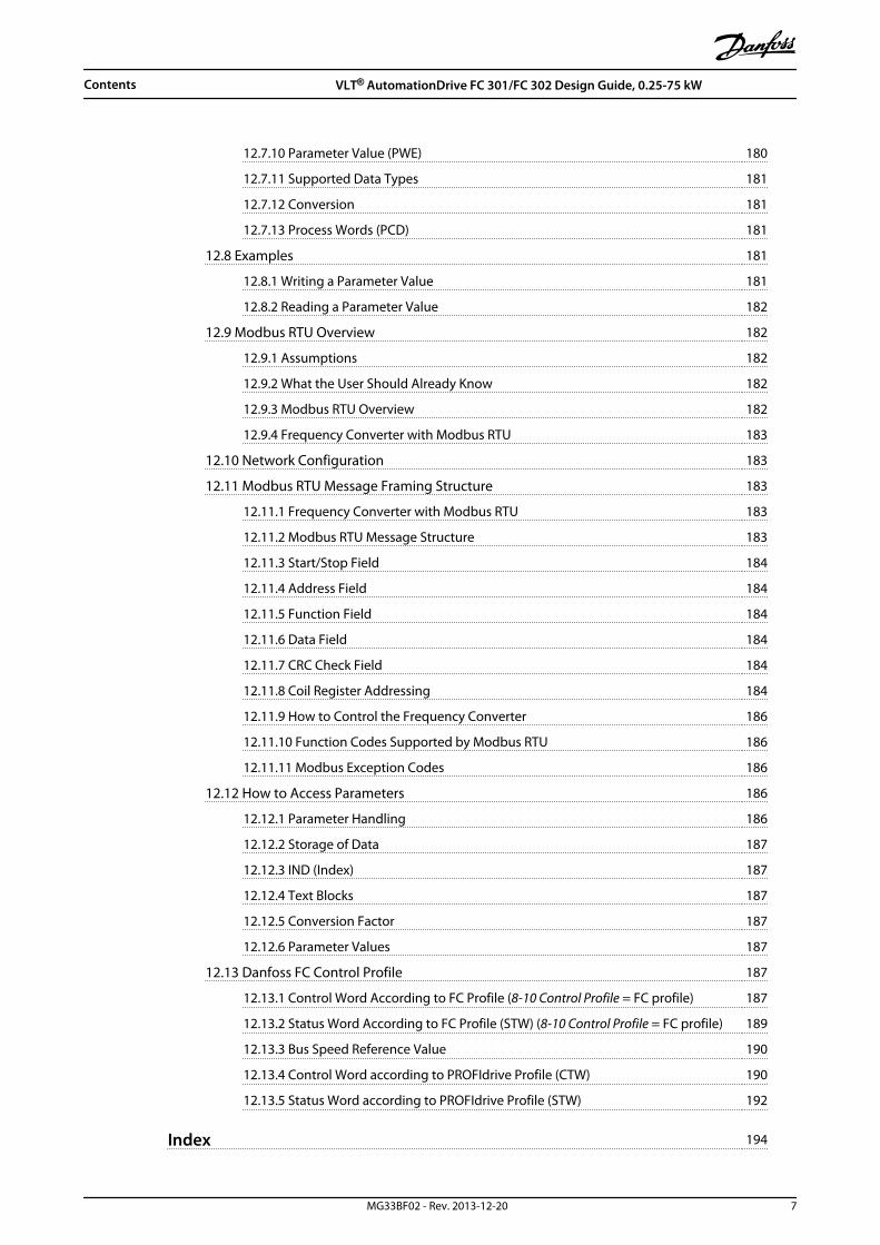
12.7.10 Parameter Value (PWE) 180
12.7.11 Supported Data Types 181
12.7.12 Conversion 181
12.7.13 Process Words (PCD) 181
12.8 Examples 181
12.8.1 Writing a Parameter Value 181
12.8.2 Reading a Parameter Value 182
12.9 Modbus RTU Overview 182
12.9.1 Assumptions 182
12.9.2 What the User Should Already Know 182
12.9.3 Modbus RTU Overview 182
12.9.4 Frequency Converter with Modbus RTU 183
12.10 Network Configuration 183
12.11 Modbus RTU Message Framing Structure 183
12.11.1 Frequency Converter with Modbus RTU 183
12.11.2 Modbus RTU Message Structure 183
12.11.3 Start/Stop Field 184
12.11.4 Address Field 184
12.11.5 Function Field 184
12.11.6 Data Field 184
12.11.7 CRC Check Field 184
12.11.8 Coil Register Addressing 184
12.11.9 How to Control the Frequency Converter 186
12.11.10 Function Codes Supported by Modbus RTU 186
12.11.11 Modbus Exception Codes 186
12.12 How to Access Parameters 186
12.12.1 Parameter Handling 186
12.12.2 Storage of Data 187
12.12.3 IND (Index) 187
12.12.4 Text Blocks 187
12.12.5 Conversion Factor 187
12.12.6 Parameter Values 187
12.13 Danfoss FC Control Profile 187
12.13.1 Control Word According to FC Profile (8-10 Control Profile = FC profile) 187
12.13.2 Status Word According to FC Profile (STW) (8-10 Control Profile = FC profile) 189
12.13.3 Bus Speed Reference Value 190
12.13.4 Control Word according to PROFIdrive Profile (CTW) 190
12.13.5 Status Word according to PROFIdrive Profile (STW) 192
Index 194
Contents VLT® AutomationDrive FC 301/FC 302 Design Guide, 0.25-75 kW
MG33BF02 - Rev. 2013-12-20 7

1 Introduction
1.1 Purpose of the Design Guide
The Design Guide provides information required forintegration of the frequency converter in a diversity ofapplications.
VLT® is a registered trademark.
1.2 Additional Resources
Other resources are available to understand advancedfrequency converter operation, programming, anddirectives compliance.
• The Operating Instructions provide detailedinformation for the installation and start up ofthe frequency converter.
• The Programming Guide provides greater detail inhow to work with parameters and manyapplication examples.
• The VLT® Safe Torque Off Operating Instructionsdescribe how to use Danfoss frequencyconverters in functional safety applications.
• Supplemental publications and manuals areavailable from Danfoss. See danfoss.com/Product/Literature/Technical+Documentation.htm forlistings.
• Optional equipment is available that may changesome of the information described in thesepublications. Be sure to see the instructionssupplied with the options for specificrequirements.
Contact a Danfoss supplier or go to www.danfoss.com foradditional information.
1.3 Abbreviations, Symbols andConventions
Conventions Numbered lists indicate procedures.Bullet lists indicate other information and description ofillustrations.Italicised text indicates
• cross reference
• link
• footnote
• parameter name, parameter group name,parameter option
60° AVM 60° Asynchronous Vector Modulation
A Ampere/AMP
AC Alternating current
AD Air discharge
AI Analog Input
AMA Automatic Motor Adaptation
AWG American wire gauge
°C Degrees Celsius
CD Contant discharge
CM Common mode
CT Constand Torque
DC Direct current
DI Digital Input
DM Differential mode
D-TYPE Drive Dependent
EMC Electro Magnetic Compatibility
ETR Electronic Thermal Relay
fJOG Motor frequency when jog function isactivated
fM Motor frequency
fMAX The maximum output frequency the frequencyconverter applies on its output
fMIN The minimum motor frequency fromfrequency converter
fM,N Nominal motor frequency
FC Frequency converter
g Gram
Hiperface® Hiperface® is a registered trademark byStegmann
hp Horsepower
HTL HTL encoder (10-30 V) pulses - High-voltageTransistor Logic
Hz Hertz
IINV Rated Inverter Output Current
ILIM Current limit
IM,N Nominal motor current
IVLT,MAX The maximum output current
IVLT,N The rated output current supplied by thefrequency converter
kHz Kilohertz
LCP Local Control Panel
lsb Least significant bit
m Meter
mA Milliampere
MCM Mille Circular Mil
MCT Motion Control Tool
mH Millihenry Inductance
min Minute
ms Millisecond
msb Most significant bit
Introduction VLT® AutomationDrive FC 301/FC 302 Design Guide, 0.25-75 kW
8 MG33BF02 - Rev. 2013-12-20
11

ηVLT Efficiency of the frequency converter definedas ratio between power output and powerinput
nF Nanofarad
NLCP Numerical Local Control Panel
Nm Newton Meters
ns Synchronous Motor Speed
On-line/Off-lineParameters
Changes to on-line parameters are activatedimmediately after the data value is changed
Pbr,cont. Rated power of the brake resistor (averagepower during continuous braking)
PCB Printed Circuit Board
PCD Process Data
PELV Protective Extra Low Voltage
Pm Frequency converter nominal output power asHO
PM,N Nominal motor power
PM motor Permanent Magnet motor
Process PID The PID regulator maintains the desired speed,pressure, temperature, etc.
Rbr,nom The nominal resistor value that ensures abrake power on motor shaft of 150/160% for 1minute
RCD Residual Current Device
Regen Regenerative terminals
Rmin Minimum permissible brake resistor value byfrequency converter
RMS Root Mean Square
RPM Revolutions Per Minute
Rrec Resistor value and resistance of the brakeresistor
s Second
SFAVM Stator Flux oriented Asynchronous VectorModulation
STW Status Word
SMPS Switch Mode Power Supply
THD Total Harmonic Distortion
TLIM Torque limit
TTL TTL encoder (5 V) pulses - Transistor TransistorLogic
UM,N Nominal motor voltage
V Volts
VT Variable Torque
VVC+ Voltage Vector Control
Table 1.1 Abbreviations
The following symbols are used in this document:
WARNINGIndicates a potentially hazardous situation which couldresult in death or serious injury.
CAUTIONIndicates a potentially hazardous situation which couldresult in minor or moderate injury. It may also be usedto alert against unsafe practices.
NOTICEIndicates important information, including situations thatmay result in damage to equipment or property.
1.4 Definitions
CoastThe motor shaft is in free mode. No torque on motor.
Brake ResistorThe brake resistor is a module capable of absorbing thebrake power generated in regenerative braking. Thisregenerative braking power increases the intermediatecircuit voltage and a brake chopper ensures that thepower is transmitted to the brake resistor.
CT CharacteristicsConstant torque characteristics used for all applicationssuch as conveyor belts, displacement pumps and cranes.
InitialisingIf initialising is carried out (14-22 Operation Mode), thefrequency converter returns to the default setting.
Intermittent Duty CycleAn intermittent duty rating refers to a sequence of dutycycles. Each cycle consists of an on-load and an off-loadperiod. The operation can be either periodic duty or non-periodic duty.
Set-upSave parameter settings in 4 set-ups. Change between the4 parameter set-ups and edit one set-up, while anotherset-up is active.
Slip CompensationThe frequency converter compensates for the motor slipby giving the frequency a supplement that follows themeasured motor load keeping the motor speed almostconstant.
Smart Logic Control (SLC)The SLC is a sequence of user defined actions executedwhen the associated user defined events are evaluated astrue by the Smart Logic Controller. (Parameter group 13-**Smart Logic.
FC Standard BusIncludes RS-485 bus with FC protocol or MC protocol. See8-30 Protocol.
Thermistor A temperature-dependent resistor placed where thetemperature is to be monitored (frequency converter ormotor).
Introduction VLT® AutomationDrive FC 301/FC 302 Design Guide, 0.25-75 kW
MG33BF02 - Rev. 2013-12-20 9
1 1

TripA state entered in fault situations, e.g. if the frequencyconverter is subject to an overtemperature or when thefrequency converter is protecting the motor, process ormechanism. Restart is prevented until the cause of thefault has disappeared and the trip state is cancelled byactivating reset or, in some cases, by being programmedto reset automatically. Trip may not be used for personalsafety.
Trip LockedA state entered in fault situations when the frequencyconverter is protecting itself and requiring physicalintervention, e.g. if the frequency converter is subject to ashort circuit on the output. A locked trip can only becancelled by cutting off mains, removing the cause of thefault, and reconnecting the frequency converter. Restart isprevented until the trip state is cancelled by activatingreset or, in some cases, by being programmed to resetautomatically. Trip may not be used for personal safety.
VT CharacteristicsVariable torque characteristics used for pumps and fans.
Power FactorThe True Power Factor (lambda) takes all the harmonicsinto consideration and is always smaller than the PowerFactor (cosphi) that only considers the 1st harmonics ofcurrent and voltage.
cosϕ= P kWP kVA = Uλ x Iλ x cosϕ
Uλ x IλCosphi is also known as displacement power factor.
Both lambda and cosphi are stated for Danfoss VLT®
frequency converters in chapter 6.2.1 Mains Supply.
The power factor indicates to which extent the frequencyconverter imposes a load on the mains supply. The lower the power factor, the higher the IRMS for thesame kW performance.
In addition, a high power factor indicates that the differentharmonic currents are low.All Danfoss frequency converters have built-in DC coils inthe DC link to have a high power factor and to reduce theTHD on the main supply.
1.5 Document and Software Version
This manual is regularly reviewed and updated. Allsuggestions for improvement are welcome. Table 1.2 showsthe document version and the corresponding softwareversion.
Edition Remarks Software version
MG33BFxx Replaces MG33BExx 6.72
Table 1.2 Document and Software Version
1.6 Regulatory Compliance
Frequency converters are designed in compliance with thedirectives described in this section.
1.6.1 CE Mark
The CE mark (Communauté européenne) indicates that theproduct manufacturer conforms to all applicable EUdirectives. The 3 EU directives applicable to the design andmanufacture of frequency converters are the directive low-voltage, the EMC directive, and (for units with anintegrated safety function) the machinery directive.
The CE mark is intended to eliminate technical barriers tofree trade between the EC and EFTA states inside the ECU.The CE mark does not regulate the quality of the product.Technical specifications cannot be deduced from the CEmark.
1.6.1.1 Low Voltage Directive
Frequency converters are classified as electroniccomponents and must be CE labelled in accordance withthe low-voltage directive. The directive applies to allelectrical equipment in the 50–1000 V AC and the 75–1600V DC voltage ranges.
The directive mandates that the equipment design mustensure the safety and health of people and livestock arenot endangered and the preservation of material worth solong as the equipment is properly installed, maintained,and used as intended. Danfoss CE-labels comply with thelow-voltage directive and provide a declaration ofconformity upon request.
1.6.1.2 EMC Directive
Electromagnetic compatibility (EMC) means that electro-magnetic interference between apparatus does not hindertheir performance. The basic protection requirement of theEMC Directive 2004/108/EC states that devices thatgenerate electromagnetic interference (EMI), or whoseoperation could be affected by EMI, must be designed tolimit the generation of electromagnetic interference andshall have a suitable degree of immunity to EMI whenproperly installed, maintained, and used as intended.
A frequency converter can be used as stand-alone deviceor as part of a more complex installation. Devices used asstand alone or as part of a system must bear the CE mark.Systems must not be CE marked but must comply with thebasic protection requirements of the EMC directive.
Introduction VLT® AutomationDrive FC 301/FC 302 Design Guide, 0.25-75 kW
10 MG33BF02 - Rev. 2013-12-20
11
1.6.1.3 Machinery Directive
Frequency converters are classified as electroniccomponents subject to the low-voltage directive, howeverfrequency converters with an integrated safety functionmust comply with the machinery directive 2006/42/EC.Frequency converters without safety function do not fallunder the machinery directive. If a frequency converter isintegrated into machinery system, Danfoss providesinformation on safety aspects relating to the frequencyconverter.
Machinery Directive 2006/42/EC covers a machineconsisting of an aggregate of interconnected componentsor devices of which at least one is capable of mechanicalmovement. The directive mandates that the equipmentdesign must ensure the safety and health of people andlivestock are not endangered and the preservation ofmaterial worth so long as the equipment is properlyinstalled, maintained, and used as intended.
When frequency converters are used in machines with atleast one moving part, the machine manufacturer mustprovide declaration stating compliance with all relevantstatutes and safety measures. Danfoss CE-labels complywith the machinery directive for frequency converters withan integrated safety function and provide a declaration ofconformity upon request.
1.6.2 UL Compliance
UL Listed
Illustration 1.1 UL
NOTICEFrequency converters of enclosure type T7 (525-690 V)are not certified for UL.
The frequency converter complies with UL508C thermalmemory retention requirements. For more information,refer to the section Motor Thermal Protection in the DesignGuide.
1.6.3 C-tick Compliance
1.6.4 Marine Compliance
For compliance with the European Agreement concerningInternational Carriage of Dangerous Goods by InlandWaterways (ADN), refer to .
1.7 Disposal Instruction
Do not dispose of equipment containingelectrical components together withdomestic waste.Collect it separately in accordance withlocal and currently valid legislation.
Table 1.3 Disposal Instruction
1.8 Safety
Frequency converters contain high voltage componentsand have the potential for fatal injury if handledimproperly. Only trained technicians should install andoperate the equipment. No repair work should beattempted without first removing power from thefrequency converter and waiting the designated amount oftime for stored electrical energy to dissipate.
Refer to the Operating Instructions, shipped with the unitand available online for:
• discharge time, and
• detailed safety instructions and warnings.
Strict adherence to safety precautions and notices ismandatory for safe operation of the frequency converter.
Introduction VLT® AutomationDrive FC 301/FC 302 Design Guide, 0.25-75 kW
MG33BF02 - Rev. 2013-12-20 11
1 1
2 Safety
2.1 Safety Symbols
The following symbols are used in this document:
WARNINGIndicates a potentially hazardous situation which couldresult in death or serious injury.
CAUTIONIndicates a potentially hazardous situation which couldresult in minor or moderate injury. It may also be usedto alert against unsafe practices.
NOTICEIndicates important information, including situations thatmay result in damage to equipment or property.
2.2 Qualified Personnel
Correct and reliable transport, storage, installation,operation and maintenance are required for the trouble-free and safe operation of the frequency converter. Onlyqualified personnel is allowed to install or operate thisequipment.
Qualified personnel is defined as trained staff, who areauthorised to install, commission, and maintain equipment,systems and circuits in accordance with pertinent laws andregulations. Additionally, the personnel must be familiarwith the instructions and safety measures described in thisdocument.
2.3 Safety Precautions
WARNINGHIGH VOLTAGEFrequency converters contain high voltage whenconnected to AC mains input power. Failure to performinstallation, start-up, and maintenance by qualifiedpersonnel could result in death or serious injury.
• Installation, start-up, and maintenance must beperformed by qualified personnel only.
WARNINGUNINTENDED STARTWhen the frequency converter is connected to AC mains,the motor may start at any time, causing risk of death,serious injury, equipment, or property damage. Themotor can start by means of an external switch, a serialbus command, an input reference signal from the LCP, orafter a cleared fault condition.
1. Disconnect the frequency converter from mainswhenever personal safety considerations makeit necessary to avoid unintended motor start.
2. Press [Off] on the LCP, before programmingparameters.
3. The frequency converter, motor, and any drivenequipment must be in operational readinesswhen the frequency converter is connected toAC mains.
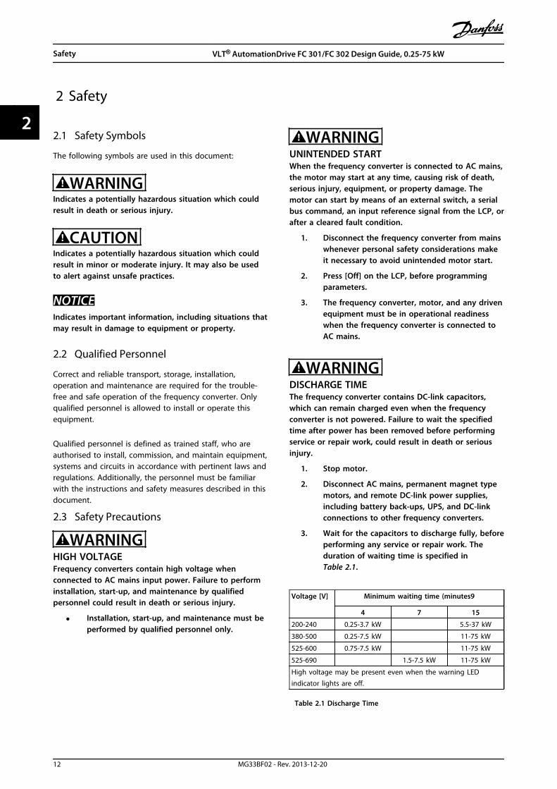
WARNINGDISCHARGE TIMEThe frequency converter contains DC-link capacitors,which can remain charged even when the frequencyconverter is not powered. Failure to wait the specifiedtime after power has been removed before performingservice or repair work, could result in death or seriousinjury.
1. Stop motor.
2. Disconnect AC mains, permanent magnet typemotors, and remote DC-link power supplies,including battery back-ups, UPS, and DC-linkconnections to other frequency converters.
3. Wait for the capacitors to discharge fully, beforeperforming any service or repair work. Theduration of waiting time is specified inTable 2.1.
Voltage [V] Minimum waiting time (minutes9
4 7 15
200-240 0.25-3.7 kW 5.5-37 kW
380-500 0.25-7.5 kW 11-75 kW
525-600 0.75-7.5 kW 11-75 kW
525-690 1.5-7.5 kW 11-75 kW
High voltage may be present even when the warning LEDindicator lights are off.
Table 2.1 Discharge Time
Safety VLT® AutomationDrive FC 301/FC 302 Design Guide, 0.25-75 kW
12 MG33BF02 - Rev. 2013-12-20
22

WARNINGLEAKAGE CURRENT HAZARDLeakage currents exceed 3.5 mA. Failure to ground thefrequency converter properly could result in death orserious injury.
• Ensure correct grounding of the equipment bya certified electrical installer.
WARNINGEQUIPMENT HAZARDContact with rotating shafts and electrical equipmentcan result in death or serious injury.
• Ensure that only trained and qualifiedpersonnel perform installation, start up, andmaintenance.
• Ensure that electrical work conforms to nationaland local electrical codes.
• Follow the procedures in this manual.
CAUTIONWINDMILLINGUnintended rotation of permanent magnet motorscauses risk of personal injury and equipment damage.
• Ensure that permanent magnet motors areblocked to prevent unintended rotation.
CAUTIONPOTENTIAL HAZARD IN THE EVENT OF INTERNALFAILURERisk of personal injury when the frequency converter isnot properly closed.
• Before applying power, ensure all safety coversare in place and securely fastened.
Safety VLT® AutomationDrive FC 301/FC 302 Design Guide, 0.25-75 kW
MG33BF02 - Rev. 2013-12-20 13
2 2

3 Basic Operating Principles
3.1 General
This chapter provides an overview of the frequencyconverter’s primary assemblies and circuitry. It is intendedto describe the internal electrical and signal processingfunctions. A description of the internal control structure isalso included.
Also described are automated and optional frequencyconverter functions available for designing robustoperating systems with sophisticated control and statusreporting performance.
3.2 Description of Operation
The frequency converter supplies a regulated amount ofmains AC power to a standard 3 phase induction motor tocontrol the motor speed. The frequency converter suppliesvariable frequency and voltage to the motor.
The frequency converter is divided into four main modules.
• Rectifier
• Intermediate circuit
• Inverter
• Control and regulation
In chapter 3.3 Sequence of Operation, these modules arecovered in greater detail and describe how power andcontrol signals move within the frequency converter.
Illustration 3.1 Internal Control Logic
3.3 Sequence of Operation
3.3.1 Rectifier Section
When power is first applied to the frequency converter, itenters through the input terminals (L1, L2, and L3) and onto the disconnect and/or RFI filter option, depending onthe unit's configuration.
3.3.2 Intermediate Section
Following the rectifier section, voltage passes to theintermediate section. This rectified voltage is smoothed byan sinewave filter circuit consisting of the DC bus inductorand the DC bus capacitor bank.
The DC bus inductor provides series impedance tochanging current. This aids the filtering process whilereducing harmonic distortion to the input AC currentwaveform normally inherent in rectifier circuits.
3.3.3 Inverter Section
In the inverter section, once a run command and speedreference are present, the IGBTs begin switching to createthe output waveform. This waveform, as generated by theDanfoss VVC+ PWM principle at the control card, providesoptimal performance and minimal losses in the motor.
3.3.4 Brake Option
For frequency converters equipped with the dynamic brakeoption, a brake IGBT along with terminals 81(R-) and 82(R+) are included for connecting an external brake resistor.
The function of the brake IGBT is to limit the voltage inthe intermediate circuit, whenever the maximum voltagelimit is exceeded. It does this by switching the externallymounted resistor across the DC bus to remove excess DCvoltage present on the bus capacitors. Excess DC busvoltage is generally a result of an overhauling load causingregenerative energy returned to the DC bus. This occurs,for example, when the load drives the motor causing thevoltage to return to the DC bus circuit.
Placing the brake resistor externally has the advantages ofselecting the resistor based on application need,dissipating the energy outside of the control panel, andprotecting the converter from overheating if the brakeresistor is overloaded.
Basic Operating Principles VLT® AutomationDrive FC 301/FC 302 Design Guide, 0.25-75 kW
14 MG33BF02 - Rev. 2013-12-20
33

The brake IGBT gate signal originates on the control cardand is delivered to the brake IGBT via the power card andgate drive card. Additionally, the power and control cardsmonitor the brake IGBT and brake resistor connection forshort circuits and overloads.
3.3.5 Load Sharing
Units with the built-in load sharing option containterminals (+) 89 DC and (–) 88 DC. Within the frequencyconverter, these terminals connect to the DC bus in frontof the DC link reactor and bus capacitors.
The use of the load sharing terminals can take on 2different configurations.
In one method, the terminals are used to tie the DC-buscircuits of multiple frequency converters together. Thisallows one unit that is in a regenerative mode to share itsexcess bus voltage with another unit that is running amotor. Load sharing in this manner can reduce the needfor external dynamic brake resistors while also savingenergy. In theory, the number of units that can beconnected in this way is infinite, however, each unit mustbe the same voltage rating. In addition, depending on thesize and number of units, it may be necessary to install DCreactors and DC fuses in the DC link connections and ACreactors on the mains. Attempting such a configurationrequires specific considerations and should not beattempted without first consulting Danfoss applicationengineering.
In the second method, the frequency converter is poweredexclusively from a DC source. This is a bit morecomplicated. First, a DC source is required. Second, ameans to soft charge the DC bus at power up is alsorequired. Last, a voltage source is required to power thefans within the unit. Again such a configuration should notbe attempted with out first consulting Danfoss applicationengineering.
3.4 Control Interface
3.4.1 Control Principle
The frequency converter receives control input fromseveral sources.
• Local control panel (hand mode)
• Programmable analog, digital, and analog/digitalcontrol terminals (auto mode)
• The RS-485, USB, or serial communication ports(auto mode)
When wired and properly programmed, the controlterminals provide feedback, reference, and other inputsignals to the frequency converter; output status and faultconditions from the frequency converter, relays to operateauxiliary equipment, and serial communication interface. A24 V common is also provided. Control terminals areprogrammable for various functions by selecting parameteroptions through the local control panel (LCP) on the frontof the unit or external sources. Most control wiring iscustomer supplied unless factory ordered.
Basic Operating Principles VLT® AutomationDrive FC 301/FC 302 Design Guide, 0.25-75 kW
MG33BF02 - Rev. 2013-12-20 15
3 3

3.5 Wiring Schematic
130B
D59
9.10
3-phasepowerinput
DC bus Switch ModePower Supply
Motor
Analog Output
Interface
relay1
relay2
ON=TerminatedOFF=Open
Brakeresistor
91 (L1)92 (L2)93 (L3)
PE
88 (-)89 (+)
50 (+10 V OUT)
53 (A IN)
54 (A IN)
55 (COM A IN)0/4-20 mA
12 (+24 V OUT)
13 (+24 V OUT)
37 (D IN)
18 (D IN)
20 (COM D IN)
10 V DC15 mA 130/200 mA
+ - + -
(U) 96(V) 97(W) 98(PE) 99
(COM A OUT) 39
(A OUT) 42
(P RS-485) 68
(N RS-485) 69
(COM RS-485) 61
0 V
5V
S801
0/4-20 mA
RS-485RS-485
03
+10 V DC0/-10 V DC -
+10 V DC
+10 V DC0/4-20 mA
0/-10 V DC-
240 V AC, 2 A
24 V DC
02
01
05
04
06
24 V (NPN) 0 V (PNP)
0 V (PNP)24 V (NPN)
19 (D IN)
24 V (NPN) 0 V (PNP)27
24 V
0 V
(D IN/OUT)
0 V (PNP)24 V (NPN)
(D IN/OUT)
0 V
24 V29
24 V (NPN) 0 V (PNP)
0 V (PNP)24 V (NPN)
33 (D IN)
32 (D IN)
12
ON
S201
ON2
1S202ON=0/4-20 mAOFF=0/-10 V DC - +10 V DC
95
P 5-00
21 O
N
S801
(R+) 82
(R-) 81
: Chassis
: Ground
**
240 V AC, 2 A
400 V AC, 2 A
*
*
*
Illustration 3.2 Basic Wiring Schematic
A=Analog, D=Digital*Terminal 37 (optional) is used for Safe Torque Off. For Safe Torque Off installation instructions, refer to the Safe Torque OffOperating Instructions for Danfoss VLT® Frequency Converters. Terminal 37 is not included in FC 301 (except enclosure typeA1). Relay 2 and terminal 29 have no function in FC 301.**Do not connect cable screen.
Basic Operating Principles VLT® AutomationDrive FC 301/FC 302 Design Guide, 0.25-75 kW
16 MG33BF02 - Rev. 2013-12-20
33

130B
D52
9.11
1
2
3
4
5
6
78
PE
UVW
9
L1L2L3PE
1011
1 PLC 7 Motor, 3-phase and PE (screened)
2 Frequency converter 8 Mains, 3-phase and reinforced PE (not screened)
3 Output contactor 9 Control wiring (screened)
4 Cable clamp 10 Potential equalisation min. 16 mm2 (0.025 in)
5 Cable insulation (stripped)11
Clearance between control cable, motor cable and mains cable:Min. 200 mm6 Cable gland
Illustration 3.3 EMC-compliant Electrical Connection
For more information about EMC, see chapter 4.1.15 EMC Compliance
Basic Operating Principles VLT® AutomationDrive FC 301/FC 302 Design Guide, 0.25-75 kW
MG33BF02 - Rev. 2013-12-20 17
3 3
NOTICEEMC INTERFERENCEUse screened cables for motor and control wiring, andseparate cables for input power, motor wiring andcontrol wiring. Failure to isolate power, motor andcontrol cables can result in unintended behaviour orreduced performance. Minimum 200 mm (7.9 in)clearance between power, motor and control cables isrequired.
3.6 Controls
3.6.1 Control Principle
A frequency converter rectifies AC voltage from mains intoDC voltage, after which this DC voltage is converted into aAC current with a variable amplitude and frequency.
The motor is supplied with variable voltage/current andfrequency, which enables variable speed control of 3-phased, standard asynchronous motors and permanentmagnet motors.
The frequency converter is capable of controlling eitherthe speed or the torque on the motor shaft. Setting1-00 Configuration Mode determines the type of control.
Speed control
There are 2 types of speed control:
• Speed open loop control which does not requireany feedback from motor (sensorless).
• Speed closed loop PID control requires a speedfeedback to an input. A properly optimised speedclosed loop control has higher accuracy than aspeed open loop control.
Selects which input to use as speed PID feedback in7-00 Speed PID Feedback Source.
Torque control The torque control function is used in applications wherethe torque on motor output shaft is controlling theapplication as tension control. Torque control can beselected in 1-00 Configuration Mode, either in VVC+ [4]Torque open loop or Flux control closed loop with [2] motorspeed feedback. Torque setting is done by setting ananalog, digital or bus controlled reference. The max speedlimit factor is set in 4-21 Speed Limit Factor Source. Whenrunning torque control, it is recommended to make a fullAMA procedure as the correct motor data are of highimportance for optimal performance.
• Closed loop in Flux mode with encoder feedbackoffers superior performance in all 4 quadrantsand at all motor speeds.
• Open loop in VVC+ mode. The function is used inmechanical robust applications, but the accuracy
is limited. Open loop torque function worksbasically only in one speed direction. The torqueis calculated on basic of current measurementinternal in the frequency converter.
Speed/torque referenceThe reference to these controls can either be a singlerefrence or be the sum of various references includingrelatively scaled references. The handling of references isexplained in detail in chapter 3.7 Reference Handling.
Basic Operating Principles VLT® AutomationDrive FC 301/FC 302 Design Guide, 0.25-75 kW
18 MG33BF02 - Rev. 2013-12-20
33
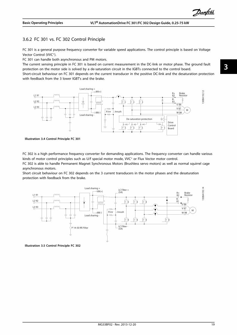
3.6.2 FC 301 vs. FC 302 Control Principle
FC 301 is a general purpose frequency converter for variable speed applications. The control principle is based on VoltageVector Control (VVC+).FC 301 can handle both asynchronous and PM motors.The current sensing principle in FC 301 is based on current measurement in the DC-link or motor phase. The ground faultprotection on the motor side is solved by a de-saturation circuit in the IGBTs connected to the control board.Short-circuit behaviour on FC 301 depends on the current transducer in the positive DC-link and the desaturation protectionwith feedback from the 3 lower IGBT's and the brake.
M
L2 92
L1 91
L3 93
89(+)
88(-)
R+82
R-81
U 96
V 97
W 98
130B
A19
2.12
InrushR inrLoad sharing -
De-saturation protection
Load sharing +
BrakeResistor
DriveControlBoard
Illustration 3.4 Control Principle FC 301
FC 302 is a high performance frequency converter for demanding applications. The frequency converter can handle variouskinds of motor control principles such as U/f special motor mode, VVC+ or Flux Vector motor control.FC 302 is able to handle Permanent Magnet Synchronous Motors (Brushless servo motors) as well as normal squirrel cageasynchronous motors.Short circuit behaviour on FC 302 depends on the 3 current transducers in the motor phases and the desaturationprotection with feedback from the brake.
InrushR inrLoad sharing -
Load sharing +
LC Filter -(5A)
LC Filter +(5A) Brake
Resistor
130B
A19
3.14
M
L2 92
L1 91
L3 93
89(+)
88(-)
R+82
R-81
U 96
V 97
W 98
P 14-50 R Filter
Illustration 3.5 Control Principle FC 302
Basic Operating Principles VLT® AutomationDrive FC 301/FC 302 Design Guide, 0.25-75 kW
MG33BF02 - Rev. 2013-12-20 19
3 3
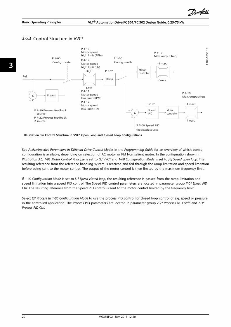
3.6.3 Control Structure in VVC+
+
_
+
_
Cong. mode
Ref.
Process
P 1-00
High
+f max.
Low
-f max.
P 4-11 Motor speedlow limit (RPM)P 4-12 Motor speedlow limit (Hz)
P 4-13 Motor speedhigh limit (RPM)
P 4-14 Motor speedhigh limit (Hz)
Motorcontroller
Ramp
SpeedPID
P 7-20 Process feedback1 sourceP 7-22 Process feedback2 source
P 7-00 Speed PID
feedback source
P 1-00Cong. mode
P 4-19Max. output freq.
-f max.
Motor controller
P 4-19Max. output freq.
+f max.
P 3-**
P 7-0*
13
0B
A0
55
.10
Illustration 3.6 Control Structure in VVC+ Open Loop and Closed Loop Configurations
See Active/Inactive Parameters in Different Drive Control Modes in the Programming Guide for an overview of which controlconfiguration is available, depending on selection of AC motor or PM Non salient motor. In the configuration shown inIllustration 3.6, 1-01 Motor Control Principle is set to [1] VVC+ and 1-00 Configuration Mode is set to [0] Speed open loop. Theresulting reference from the reference handling system is received and fed through the ramp limitation and speed limitationbefore being sent to the motor control. The output of the motor control is then limited by the maximum frequency limit.
If 1-00 Configuration Mode is set to [1] Speed closed loop, the resulting reference is passed from the ramp limitation andspeed limitation into a speed PID control. The Speed PID control parameters are located in parameter group 7-0* Speed PIDCtrl. The resulting reference from the Speed PID control is sent to the motor control limited by the frequency limit.
Select [3] Process in 1-00 Configuration Mode to use the process PID control for closed loop control of e.g. speed or pressurein the controlled application. The Process PID parameters are located in parameter group 7-2* Process Ctrl. Feedb and 7-3*Process PID Ctrl.
Basic Operating Principles VLT® AutomationDrive FC 301/FC 302 Design Guide, 0.25-75 kW
20 MG33BF02 - Rev. 2013-12-20
33
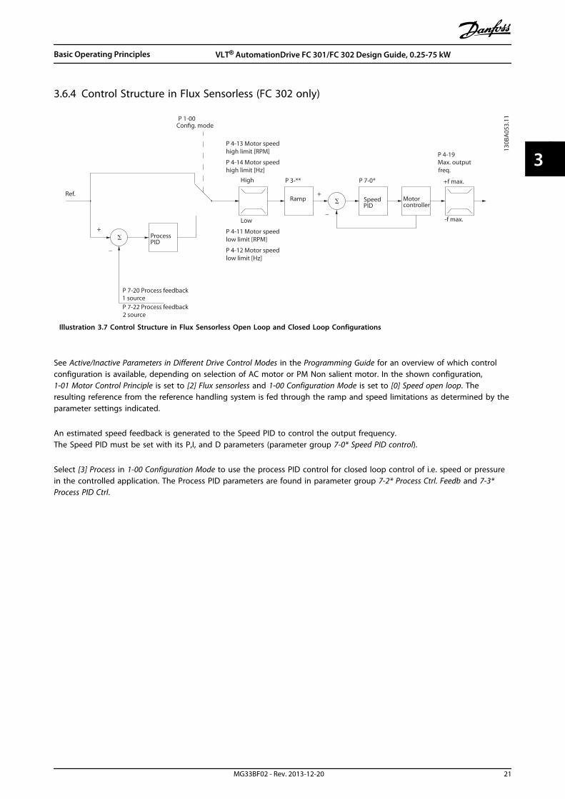
3.6.4 Control Structure in Flux Sensorless (FC 302 only)
+
_
+
_
130B
A05
3.11
Ref.
Cong. modeP 1-00
P 7-20 Process feedback1 sourceP 7-22 Process feedback2 source
ProcessPID
P 4-11 Motor speedlow limit [RPM]
P 4-12 Motor speedlow limit [Hz]
P 4-14 Motor speedhigh limit [Hz]
P 4-13 Motor speedhigh limit [RPM]
Low
High
Ramp
P 3-** +f max.
P 4-19Max. outputfreq.
Motorcontroller
-f max.
SpeedPID
P 7-0*
Illustration 3.7 Control Structure in Flux Sensorless Open Loop and Closed Loop Configurations
See Active/Inactive Parameters in Different Drive Control Modes in the Programming Guide for an overview of which controlconfiguration is available, depending on selection of AC motor or PM Non salient motor. In the shown configuration,1-01 Motor Control Principle is set to [2] Flux sensorless and 1-00 Configuration Mode is set to [0] Speed open loop. Theresulting reference from the reference handling system is fed through the ramp and speed limitations as determined by theparameter settings indicated.
An estimated speed feedback is generated to the Speed PID to control the output frequency.The Speed PID must be set with its P,I, and D parameters (parameter group 7-0* Speed PID control).
Select [3] Process in 1-00 Configuration Mode to use the process PID control for closed loop control of i.e. speed or pressurein the controlled application. The Process PID parameters are found in parameter group 7-2* Process Ctrl. Feedb and 7-3*Process PID Ctrl.
Basic Operating Principles VLT® AutomationDrive FC 301/FC 302 Design Guide, 0.25-75 kW
MG33BF02 - Rev. 2013-12-20 21
3 3

3.6.5 Control Structure in Flux with Motor Feedback (FC 302 only)
130B
A05
4.11
P 3-** P 7-0*P 7-2*
+
_
+
_
P 7-20 Process feedback1 sourceP 7-22 Process feedback2 source
P 4-11 Motor speedlow limit (RPM)P 4-12 Motor speedlow limit (Hz)
P 4-13 Motor speedhigh limit (RPM)P 4-14 Motor speedhigh limit (Hz)
High
Low
Ref. ProcessPID
SpeedPID
Ramp
P 7-00PID source
Motorcontroller
-f max.
+f max.
P 4-19Max. outputfreq.
P 1-00Cong. mode
P 1-00Cong. mode
Torque
Illustration 3.8 Control Structure in Flux with Motor Feedback Configuration (only available in FC 302)
See Active/Inactive Parameters in Different Drive Control Modes in the Programming Guide for an overview of which controlconfiguration is available, depending on selection of AC motor or PM Non salient motor. In the shown configuration,1-01 Motor Control Principle is set to [3] Flux w motor feedb and 1-00 Configuration Mode is set to [1] Speed closed loop.
The motor control in this configuration relies on a feedback signal from an encoder or resolver mounted directly on themotor (set in 1-02 Flux Motor Feedback Source).
Select [1] Speed closed loop in 1-00 Configuration Mode to use the resulting reference as an input for the Speed PID control.The Speed PID control parameters are located in parameter group 7-0* Speed PID Control.
Select [2] Torque in 1-00 Configuration Mode to use the resulting reference directly as a torque reference. Torque control canonly be selected in the Flux with motor feedback (1-01 Motor Control Principle) configuration. When this mode has beenselected, the reference uses the Nm unit. It requires no torque feedback, since the actual torque is calculated on the basis ofthe current measurement of the frequency converter.
Select [3] Process in 1-00 Configuration Mode to use the process PID control for closed loop control of e.g. speed or a processvariable in the controlled application.
Basic Operating Principles VLT® AutomationDrive FC 301/FC 302 Design Guide, 0.25-75 kW
22 MG33BF02 - Rev. 2013-12-20
33

3.6.6 PID
3.6.6.1 Speed PID Control
Speed PID Control maintains a constant motor speed regardless of the changing load on the motor.
1-00 Configuration Mode1-01 Motor Control Principle
U/f VVC+ Flux Sensorless Flux w/ enc. feedb
[0] Speed open loop ACTIVE ACTIVE ACTIVE N.A.
[1] Speed closed loop N.A. Not Active N.A. ACTIVE
[2] Torque N.A. N.A. N.A. Not Active
[3] Process Not Active Not Active Not Active N.A.
[4] Torque open loop N.A. Not Active N.A. N.A.
[5] Wobble Not Active Not Active Not Active Not Active
[6] Surface Winder Not Active Not Active Not Active N.A.
[7] Extended PID Speed OL Not Active Not Active Not Active N.A.
[8] Extended PID Speed CL N.A. Not Active N.A. Not Active
Table 3.1 Control Configurations with Active Speed Control
“N.A.” means that the specific mode is not available at all. “Not Active” means that the specific mode is available but the Speed Control is notactive in that mode.
NOTICEThe Speed Control PID works under the default parameter setting, but tuning the parameters is highly recommended tooptimise the motor control performance. The 2 Flux motor control principles are particularly dependant on propertuning to yield their full potential.
Table 3.2 sums up the characteristics that can be set-up for speed control. See VLT® AutomationDrive FC 301/FC 302Programming Guide for details on programming.
Basic Operating Principles VLT® AutomationDrive FC 301/FC 302 Design Guide, 0.25-75 kW
MG33BF02 - Rev. 2013-12-20 23
3 3

Parameter Description of function
7-00 Speed PID Feedback Source Select from which input the Speed PID should get its feedback.
7-02 Speed PID Proportional Gain The higher the value - the quicker the control. However, too high value may lead to oscillations.
7-03 Speed PID Integral TimeEliminates steady state speed error. Lower value means quick reaction. However, too low value maylead to oscillations.
7-04 Speed PID DifferentiationTime
Provides a gain proportional to the rate of change of the feedback. A setting of zero disables thedifferentiator.
7-05 Speed PID Diff. Gain Limit
If there are quick changes in reference or feedback in a given application - which means that the errorchanges swiftly - the differentiator may soon become too dominant. This is because it reacts tochanges in the error. The quicker the error changes, the stronger the differentiator gain is. The differ-entiator gain can thus be limited to allow setting of the reasonable differentiation time for slowchanges and a suitably quick gain for quick changes.
7-06 Speed PID Lowpass FilterTime
A low-pass filter that dampens oscillations on the feedback signal and improves steady stateperformance. However, too large filter time deteriorates the dynamic performance of the Speed PIDcontrol.Practical settings of parameter 7-06 taken from the number of pulses per revolution on from encoder(PPR):
Encoder PPR 7-06 Speed PID Lowpass Filter Time
512 10 ms
1024 5 ms
2048 2 ms
4096 1 ms
7-07 Speed PID Feedback GearRatio
The frequency converter multiplies the speed feedback by this ratio.
7-08 Speed PID Feed ForwardFactor
The reference signal bypasses the speed controller by the amount specified. This feature increases thedynamic performance of the speed control loop.
7-09 Speed PID Error Correctionw/ Ramp
The speed error between ramp and actual speed is held up against the setting in this parameter. If thespeed error exceeds this parameter entry, the speed error is corrected via ramping in a controlled way.
Table 3.2 Relevant Parameters for Speed Control
Programme in the order shown (see explanation of settings in the Programming Guide)In Table 3.3 it is assumed that all other parameters and switches remain at their default setting.
Function Parameter Setting1) Make sure the motor runs properly. Do the following:
Set the motor parameters using name plate data 1-2* As specified by motor name plate
Perform an Automatic Motor Adaptation 1-29 AutomaticMotor Adaptation(AMA)
[1] Enable complete AMA
2) Check the motor is running and the encoder is attached properly. Do the following:
Press [Hand On] on the LCP. Check that the motor isrunning and note in which direction it is turning(henceforth referred to as the “positive direction”).
Set a positive reference.
Go to 16-20 Motor Angle. Turn the motor slowly in thepositive direction. It must be turned so slowly (only afew RPM) that it can be determined if the value in16-20 Motor Angle is increasing or decreasing.
16-20 Motor Angle N.A. (read-only parameter) Note: An increasing valueoverflows at 65535 and starts again at 0.
If 16-20 Motor Angle is decreasing, change the encoderdirection in 5-71 Term 32/33 Encoder Direction.
5-71 Term 32/33Encoder Direction
[1] Counter clockwise (if 16-20 Motor Angle is decreasing)
3) Make sure the frequency converter limits are set to safe values
Set acceptable limits for the references. 3-02 MinimumReference3-03 MaximumReference
0 RPM (default)1500 RPM (default)
Basic Operating Principles VLT® AutomationDrive FC 301/FC 302 Design Guide, 0.25-75 kW
24 MG33BF02 - Rev. 2013-12-20
33
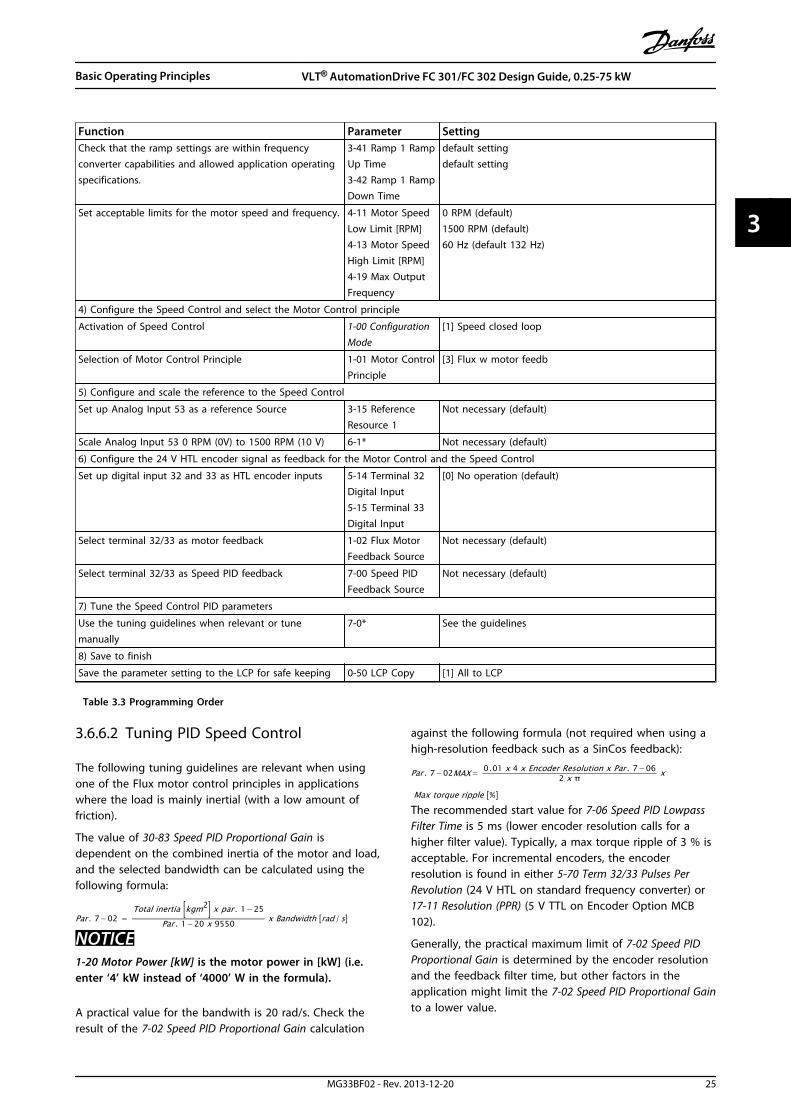
Function Parameter SettingCheck that the ramp settings are within frequencyconverter capabilities and allowed application operatingspecifications.
3-41 Ramp 1 RampUp Time3-42 Ramp 1 RampDown Time
default settingdefault setting
Set acceptable limits for the motor speed and frequency. 4-11 Motor SpeedLow Limit [RPM]4-13 Motor SpeedHigh Limit [RPM]4-19 Max OutputFrequency
0 RPM (default)1500 RPM (default)60 Hz (default 132 Hz)
4) Configure the Speed Control and select the Motor Control principle
Activation of Speed Control 1-00 ConfigurationMode
[1] Speed closed loop
Selection of Motor Control Principle 1-01 Motor ControlPrinciple
[3] Flux w motor feedb
5) Configure and scale the reference to the Speed Control
Set up Analog Input 53 as a reference Source 3-15 ReferenceResource 1
Not necessary (default)
Scale Analog Input 53 0 RPM (0V) to 1500 RPM (10 V) 6-1* Not necessary (default)
6) Configure the 24 V HTL encoder signal as feedback for the Motor Control and the Speed Control
Set up digital input 32 and 33 as HTL encoder inputs 5-14 Terminal 32Digital Input5-15 Terminal 33Digital Input
[0] No operation (default)
Select terminal 32/33 as motor feedback 1-02 Flux MotorFeedback Source
Not necessary (default)
Select terminal 32/33 as Speed PID feedback 7-00 Speed PIDFeedback Source
Not necessary (default)
7) Tune the Speed Control PID parameters
Use the tuning guidelines when relevant or tunemanually
7-0* See the guidelines
8) Save to finish
Save the parameter setting to the LCP for safe keeping 0-50 LCP Copy [1] All to LCP
Table 3.3 Programming Order
3.6.6.2 Tuning PID Speed Control
The following tuning guidelines are relevant when usingone of the Flux motor control principles in applicationswhere the load is mainly inertial (with a low amount offriction).
The value of 30-83 Speed PID Proportional Gain isdependent on the combined inertia of the motor and load,and the selected bandwidth can be calculated using thefollowing formula:
Par . 7−02 = Total inertia kgm2 x par . 1−25
Par . 1−20 x 9550 x Bandwidth rad /s
NOTICE1-20 Motor Power [kW] is the motor power in [kW] (i.e.enter ‘4’ kW instead of ‘4000’ W in the formula).
A practical value for the bandwith is 20 rad/s. Check theresult of the 7-02 Speed PID Proportional Gain calculation
against the following formula (not required when using ahigh-resolution feedback such as a SinCos feedback):
Par . 7−02MAX = 0.01 x 4 x Encoder Resolution x Par . 7−062 x π x
Max torque ripple %
The recommended start value for 7-06 Speed PID LowpassFilter Time is 5 ms (lower encoder resolution calls for ahigher filter value). Typically, a max torque ripple of 3 % isacceptable. For incremental encoders, the encoderresolution is found in either 5-70 Term 32/33 Pulses PerRevolution (24 V HTL on standard frequency converter) or17-11 Resolution (PPR) (5 V TTL on Encoder Option MCB102).
Generally, the practical maximum limit of 7-02 Speed PIDProportional Gain is determined by the encoder resolutionand the feedback filter time, but other factors in theapplication might limit the 7-02 Speed PID Proportional Gainto a lower value.
Basic Operating Principles VLT® AutomationDrive FC 301/FC 302 Design Guide, 0.25-75 kW
MG33BF02 - Rev. 2013-12-20 25
3 3

To minimise the overshoot, 7-03 Speed PID Integral Timecould be set to approx. 2.5 s (varies with the application).
Set 7-04 Speed PID Differentiation Time to 0 until everythingelse is tuned. If necessary, finish the tuning by experi-menting with small increments of this setting.
3.6.6.3 Process PID Control
Use the Process PID Control to control applicationparameters that can be measured by a sensor (i.e.pressure, temperature, flow) and be affected by theconnected motor through a pump, fan or otherwise.
Table 3.4 shows the control configurations where theProcess Control is possible. When a Flux Vector motorcontrol principle is used, take care also to tune the SpeedControl PID parameters. Refer to chapter 3.6 Controls to seewhere the Speed Control is active.
1-00 Configu-ration Mode
1-01 Motor Control Principle
U/f VVC+ FluxSensorless
Flux w/enc. feedb
[3] Process NotActive
Process Process &Speed
Process &Speed
Table 3.4 Control Configurations with Process Control
NOTICEThe Process Control PID works under the defaultparameter setting, but tuning the parameters is highlyrecommended to optimise the application controlperformance. The 2 Flux motor control principles arespecially dependant on proper Speed Control PID tuning(before tuning the Process Control PID) to yield their fullpotential.
P 7-30normal/inverse
PID
P 7-38
*(-1)
Feed forward
Ref.Handling
FeedbackHandling
% [unit]
% [unit]
%[unit]
%[speed] Scale to
speed
P 4-10Motor speeddirection
To motorcontrol
Process PID
130B
A17
8.10
_
+
0%
-100%
100%
0%
-100%
100%
Illustration 3.9 Process PID Control Diagram
Table 3.5 sums up the characteristics that can be set up for the process control.
Parameter Description of function7-20 Process CL Feedback 1 Resource Select from which Source (i.e. analog or pulse input) the Process PID should get its
feedback
7-22 Process CL Feedback 2 Resource Optional: Determine if (and from where) the Process PID should get an additionalfeedback signal. If an additional feedback source is selected, the 2 feedback signals areadded together before being used in the Process PID Control.
7-30 Process PID Normal/ Inverse Control Under [0] Normal operation, the Process Control responds with an increase of the motorspeed, if the feedback is getting lower than the reference. In the same situation, butunder [1] Inverse operation, the Process Control responds with a decreasing motor speedinstead.
7-31 Process PID Anti Windup The anti-windup function ensures that when either a frequency limit or a torque limit isreached, the integrator is set to a gain that corresponds to the actual frequency. Thisavoids integrating on an error that cannot in any case be compensated for with a speedchange. This function can be disabled by selecting [0] Off.
7-32 Process PID Start Speed In some applications, reaching the required speed/set point can take a very long time. Insuch applications it might be an advantage to set a fixed motor speed from the frequencyconverter before the process control is activated. This is done by setting a Process PIDStart Value (speed) in 7-32 Process PID Start Speed.
Basic Operating Principles VLT® AutomationDrive FC 301/FC 302 Design Guide, 0.25-75 kW
26 MG33BF02 - Rev. 2013-12-20
33

Parameter Description of function7-33 Process PID Proportional Gain The higher the value - the quicker the control. However, too large value may lead to
oscillations.
7-34 Process PID Integral Time Eliminates steady state speed error. Lower value means quick reaction. However, too smallvalue may lead to oscillations.
7-35 Process PID Differentiation Time Provides a gain proportional to the rate of change of the feedback. A setting of zerodisables the differentiator.
7-36 Process PID Diff. Gain Limit If there are quick changes in reference or feedback in a given application - which meansthat the error changes swiftly - the differentiator may soon become too dominant. This isbecause it reacts to changes in the error. The quicker the error changes, the stronger thedifferentiator gain is. The differentiator gain can thus be limited to allow setting of thereasonable differentiation time for slow changes.
7-38 Process PID Feed Forward Factor In application where there is a good (and approximately linear) correlation between theprocess reference and the motor speed necessary for obtaining that reference, the FeedForward Factor can be used to achieve better dynamic performance of the Process PIDControl.
5-54 Pulse Filter Time Constant #29 (Pulseterm. 29),5-59 Pulse Filter Time Constant #33 (Pulseterm. 33),6-16 Terminal 53 Filter Time Constant (Analogterm 53),6-26 Terminal 54 Filter Time Constant (Analogterm. 54)6-36 Term. X30/11 Filter Time Constant6-46 Term. X30/12 Filter Time Constant35-46 Term. X48/2 Filter Time Constant
If there are oscillations of the current/voltage feedback signal, these can be dampened bymeans of a low-pass filter. This time constant represents the speed limit of the ripplesoccurring on the feedback signal.Example: If the low-pass filter has been set to 0.1s, the limit speed is 10 RAD/s (thereciprocal of 0.1 s), corresponding to (10/(2 x π)) = 1.6 Hz. This means that all currents/voltages that vary by more than 1.6 oscillations per second is damped by the filter. Thecontrol is only carried out on a feedback signal that varies by a frequency (speed) of lessthan 1.6 Hz.The low-pass filter improves steady state performance, but selecting a too large filter timedeteriorates the dynamic performance of the Process PID Control.
Table 3.5 Relevant Parameters for Process Control
3.6.6.4 Advanced PID Control
Consult the VLT® AutomationDrive FC 301/FC 302Programming Guide for advanced PID control parameters
3.6.7 Internal Current Control in VVC+
Mode
When the motor current/torque exceed the torque limitsset in 4-16 Torque Limit Motor Mode, 4-17 Torque LimitGenerator Mode and 4-18 Current Limit, the integral currentlimit control is activated.When the frequency converter is at the current limit duringmotor operation or regenerative operation, it tries to getbelow the preset torque limits as quickly as possiblewithout losing control of the motor.
3.6.8 Local (Hand On) and Remote (AutoOn) Control
The frequency converter can be operated manually via thelocal control panel (LCP) or remotely via analog and digitalinputs and serial bus. If allowed in 0-40 [Hand on] Key onLCP, 0-41 [Off] Key on LCP, 0-42 [Auto on] Key on LCP, and0-43 [Reset] Key on LCP, it is possible to start and stop thefrequency converter via the LCP pressing [Hand On] and
[Off]. Alarms can be reset via [Reset]. After pressing [HandOn], the frequency converter goes into Hand mode andfollows (as default) the local reference that can be setusing the navigation keys on the LCP.
After pressing [Auto On], the frequency converter entersAuto mode and follows (as default) the remote reference.In this mode, it is possible to control the frequencyconverter via the digital inputs and various serial interfaces(RS-485, USB, or an optional fieldbus). See more aboutstarting, stopping, changing ramps and parameter set-upsetc. in parameter group 5-1* Digital Inputs or parametergroup 8-5* Serial communication.
130B
P046
.10
Handon O Auto
on Reset
Illustration 3.10 Operation Keys
Basic Operating Principles VLT® AutomationDrive FC 301/FC 302 Design Guide, 0.25-75 kW
MG33BF02 - Rev. 2013-12-20 27
3 3

Active Reference and Configuration Mode
The active reference can be either the local reference orthe remote reference.
In 3-13 Reference Site, the local reference can bepermanently selected by selecting [2] Local.To permanently select the remote reference select [1]Remote. By selecting [0] Linked to Hand/Auto (default) thereference site depends on which mode is active. (Handmode or Auto mode).
Remotereference
Localreference
Auto mode
Hand mode
Linked to hand/auto
Local
Remote
Reference
130B
A24
5.11
LCP Hand on,o and auto on keys
P 3-13Reference site
Illustration 3.11 Active Reference
Torque
Speed open/closed loop
Scale toRPM orHz
Scale toNm
Scale toprocessunit
Processclosed loop
Local
ref.
Localreference
Congurationmode
Localcongurationmode
130B
A24
6.10
P 1-00P 1-05
Illustration 3.12 Configuration Mode
[Hand On] [Auto on]Keys
3-13 ReferenceSite
Active Reference
Hand Linked to Hand/Auto
Local
Hand ⇒ Off Linked to Hand/Auto
Local
Auto Linked to Hand/Auto
Remote
Auto ⇒ Off Linked to Hand/Auto
Remote
All keys Local Local
All keys Remote Remote
Table 3.6 Conditions for Local/Remote Reference Activation
1-00 Configuration Mode determines what kind ofapplication control principle (i.e. Speed, Torque or ProcessControl) is used when the remote reference is active.1-05 Local Mode Configuration determines the kind ofapplication control principle that is used when the localreference is active. One of them is always active, but bothcannot be active at the same time.
3.7 Reference Handling
3.7.1 References
Analog ReferenceAn analog signal applied to input 53 or 54. The signal canbe either voltage 0-10 V (FC 301 and FC 302) or -10 to +10V (FC 302). Current signal 0-20 mA or 4-20 mA.
Binary ReferenceA signal applied to the serial communication port (RS-485terminals 68–69).
Preset ReferenceA defined preset reference to be set from -100% to +100%of the reference range. Selection of 8 preset references viathe digital terminals.
Pulse ReferenceA pulse reference applied to terminal 29 or 33, selected in5-13 Terminal 29 Digital Input or 5-15 Terminal 33 DigitalInput [32] Pulse time based. Scaling in parameter group 5-5*Pulse input.
RefMAX
Determines the relationship between the reference inputat 100% full scale value (typically 10 V, 20 mA) and theresulting reference. The maximum reference value set in3-03 Maximum Reference.
RefMIN
Determines the relationship between the reference inputat 0% value (typically 0 V, 0 mA, 4 mA) and the resultingreference. The minimum reference value set in3-02 Minimum Reference.
Basic Operating Principles VLT® AutomationDrive FC 301/FC 302 Design Guide, 0.25-75 kW
28 MG33BF02 - Rev. 2013-12-20
33
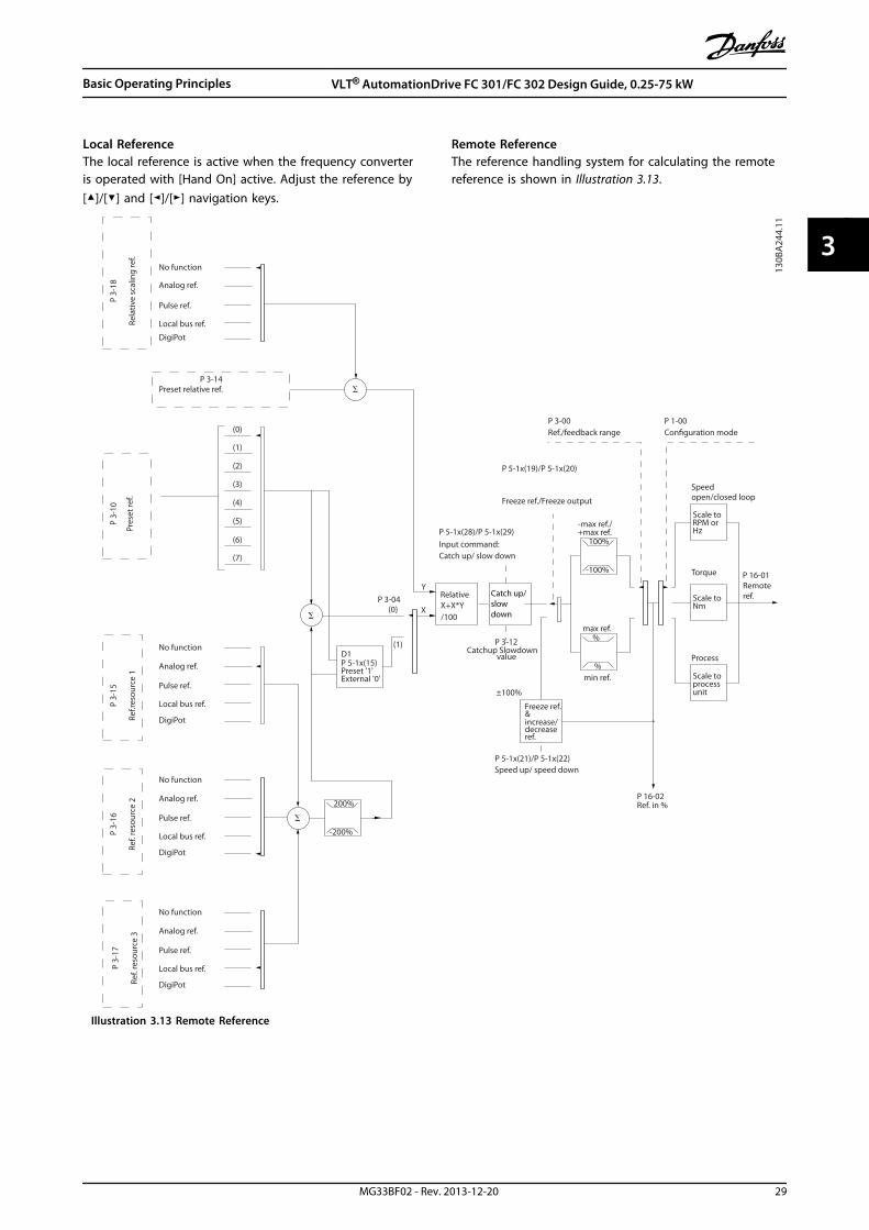
Local ReferenceThe local reference is active when the frequency converteris operated with [Hand On] active. Adjust the reference by[]/[] and []/[] navigation keys.
Remote ReferenceThe reference handling system for calculating the remotereference is shown in Illustration 3.13.
No function
Analog ref.
Pulse ref.
Local bus ref.
Preset relative ref.
Pres
et re
f.
Local bus ref.
No function
Analog ref.
Pulse ref.
Analog ref.
Pulse ref.
Local bus ref.
No function
Local bus ref.
Pulse ref.
No function
Analog ref.
Input command:Catch up/ slow down
Catchup Slowdownvalue
Freeze ref./Freeze output
Speed up/ speed down
ref.Remote
Ref. in %
-max ref./+max ref.
Scale toRPM orHz
Scale toNm
Scale toprocessunit
RelativeX+X*Y/100
DigiPot
DigiPot
DigiPot
max ref.
min ref.
DigiPot
D1P 5-1x(15)Preset '1'External '0'
Process
Torque
Speed open/closed loop
(1)
(2)
(3)
(4)
(5)
(6)
(7)
(0)
(0)
(1)
Rela
tive
scal
ing
ref.
P 3-
18
Ref.r
esou
rce
1
P 3-
15
Ref.
reso
urce
2
P 3-
16
Ref.
reso
urce
3
P 3-
17
200%
-200%
Y
X
-100%
100%
%
%
Ref./feedback rangeP 3-00
Conguration modeP 1-00
P 3-14
±100%
130B
A24
4.11
P 16-01
P 16-02
P 3-12
P 5-1x(21)/P 5-1x(22)
P 5-1x(28)/P 5-1x(29)
P 5-1x(19)/P 5-1x(20)
P 3-04
Freeze ref.& increase/decreaseref.
Catch up/slow down
P 3-
10
Illustration 3.13 Remote Reference
Basic Operating Principles VLT® AutomationDrive FC 301/FC 302 Design Guide, 0.25-75 kW
MG33BF02 - Rev. 2013-12-20 29
3 3
The remote reference is calculated once every scaninterval and initially consists of 2 types of referenceinputs:
1. X (the actual reference): A sum (see3-04 Reference Function) of up to 4 externallyselected references, comprising any combination(determined by the setting of 3-15 ReferenceResource 1, 3-16 Reference Resource 2 and3-17 Reference Resource 3) of a fixed presetreference (3-10 Preset Reference), variable analogreferences, variable digital pulse references, andvarious serial bus references in whatever unit thefrequency converter is controlled ([Hz], [RPM],[Nm] etc.).
2. Y (the relative reference): A sum of one fixedpreset reference (3-14 Preset Relative Reference)and one variable analog reference (3-18 RelativeScaling Reference Resource) in [%].
The 2 types of reference inputs are combined in thefollowing formula: Remote reference = X + X * Y/100%. Ifrelative reference is not used, set 3-18 Relative ScalingReference Resource to [0] No function and 3-14 PresetRelative Reference to 0%. The catch up/slow down functionand the freeze reference function can both be activated bydigital inputs on the frequency converter. The functionsand parameters are described in the Programming Guide.The scaling of analog references are described inparameter groups 6-1* Analog Input 1 and 6-2* AnalogInput 2, and the scaling of digital pulse references aredescribed in parameter group 5-5* Pulse Input.Reference limits and ranges are set in parameter group3-0* Reference Limits.
3.7.2 Reference Limits
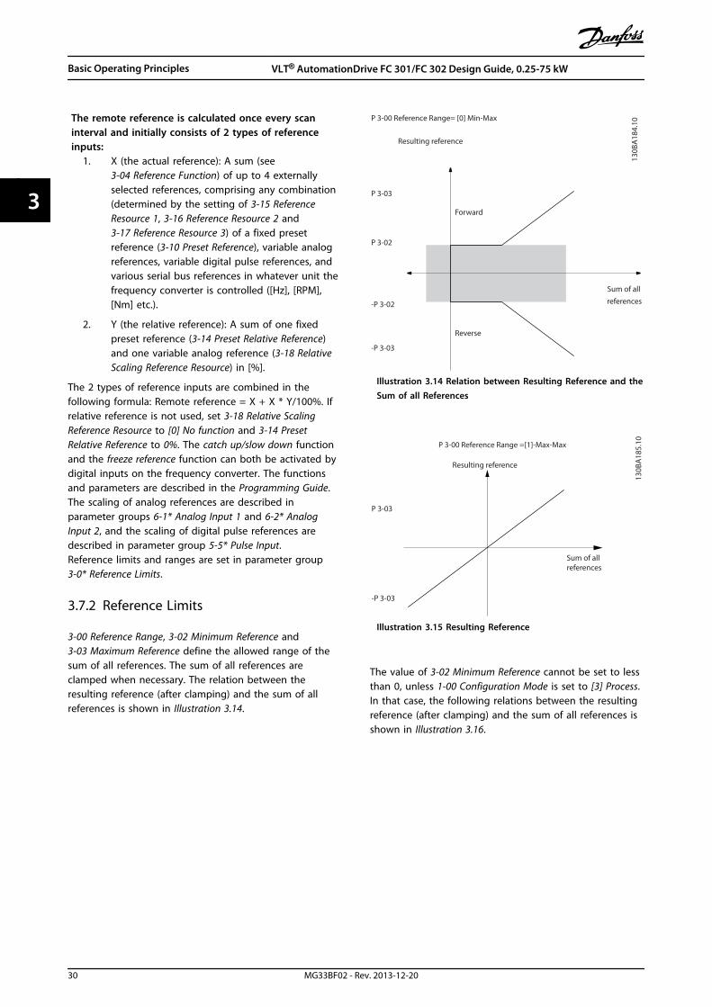
3-00 Reference Range, 3-02 Minimum Reference and3-03 Maximum Reference define the allowed range of thesum of all references. The sum of all references areclamped when necessary. The relation between theresulting reference (after clamping) and the sum of allreferences is shown in Illustration 3.14.
Resulting reference
Sum of all
references
Forward
Reverse
P 3-00 Reference Range= [0] Min-Max
130B
A18
4.10
-P 3-03
P 3-03
P 3-02
-P 3-02
Illustration 3.14 Relation between Resulting Reference and theSum of all References
P 3-00 Reference Range =[1]-Max-Max
Resulting reference
Sum of allreferences
-P 3-03
P 3-03
130B
A18
5.10
Illustration 3.15 Resulting Reference
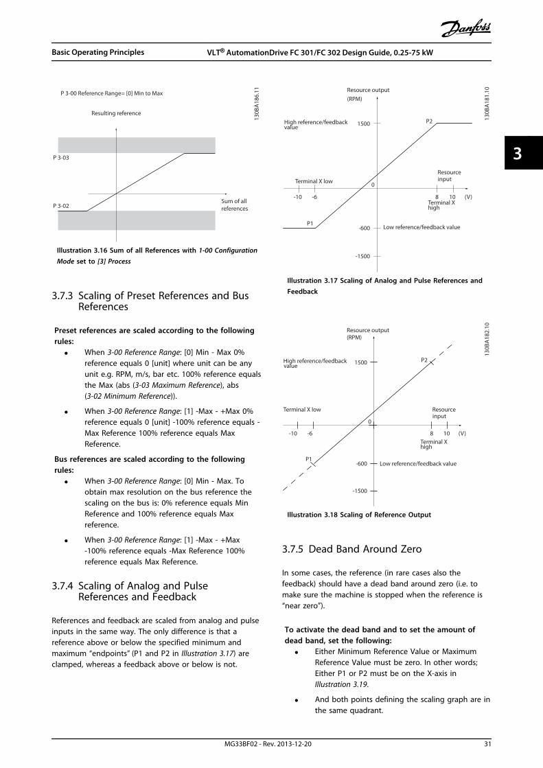
The value of 3-02 Minimum Reference cannot be set to lessthan 0, unless 1-00 Configuration Mode is set to [3] Process.In that case, the following relations between the resultingreference (after clamping) and the sum of all references isshown in Illustration 3.16.
Basic Operating Principles VLT® AutomationDrive FC 301/FC 302 Design Guide, 0.25-75 kW
30 MG33BF02 - Rev. 2013-12-20
33
130B
A18
6.11
P 3-03
P 3-02Sum of allreferences
P 3-00 Reference Range= [0] Min to Max
Resulting reference
Illustration 3.16 Sum of all References with 1-00 ConfigurationMode set to [3] Process
3.7.3 Scaling of Preset References and BusReferences
Preset references are scaled according to the followingrules:
• When 3-00 Reference Range: [0] Min - Max 0%reference equals 0 [unit] where unit can be anyunit e.g. RPM, m/s, bar etc. 100% reference equalsthe Max (abs (3-03 Maximum Reference), abs(3-02 Minimum Reference)).
• When 3-00 Reference Range: [1] -Max - +Max 0%reference equals 0 [unit] -100% reference equals -Max Reference 100% reference equals MaxReference.
Bus references are scaled according to the followingrules:
• When 3-00 Reference Range: [0] Min - Max. Toobtain max resolution on the bus reference thescaling on the bus is: 0% reference equals MinReference and 100% reference equals Maxreference.
• When 3-00 Reference Range: [1] -Max - +Max-100% reference equals -Max Reference 100%reference equals Max Reference.
3.7.4 Scaling of Analog and PulseReferences and Feedback
References and feedback are scaled from analog and pulseinputs in the same way. The only difference is that areference above or below the specified minimum andmaximum “endpoints” (P1 and P2 in Illustration 3.17) areclamped, whereas a feedback above or below is not.
(RPM)Resource output
ResourceinputTerminal X low
Terminal Xhigh
Low reference/feedback value
High reference/feedback value
130B
A18
1.10
-1500
-6 8 (V)
1500
-10 10
P1
P2
0
-600
Illustration 3.17 Scaling of Analog and Pulse References andFeedback
(RPM)Resource output
Resourceinput
Terminal X low
Terminal Xhigh
Low reference/feedback value
High reference/feedback value
130B
A18
2.10
-1500
-6 8 (V)
1500
-10 10
P1
P2
0
-600
Illustration 3.18 Scaling of Reference Output
3.7.5 Dead Band Around Zero
In some cases, the reference (in rare cases also thefeedback) should have a dead band around zero (i.e. tomake sure the machine is stopped when the reference is“near zero”).
To activate the dead band and to set the amount ofdead band, set the following:
• Either Minimum Reference Value or MaximumReference Value must be zero. In other words;Either P1 or P2 must be on the X-axis inIllustration 3.19.
• And both points defining the scaling graph are inthe same quadrant.
Basic Operating Principles VLT® AutomationDrive FC 301/FC 302 Design Guide, 0.25-75 kW
MG33BF02 - Rev. 2013-12-20 31
3 3

The size of the dead band is defined by either P1 or P2 asshown in Illustration 3.19.
(RPM)
Resource output
Resourceinput
Quadrant 2
Quadrant 3
Quadrant 1
Quadrant 4
Terminal Xlow
Terminal Xhigh
Low reference/feedback value
High reference/feedback value
-1 1
130B
A17
9.10
-1500
-6 6 (V)
1500
-10 10
P1
P2
0
Illustration 3.19 Dead Band
(RPM)Resource output
Resourceinput
Quadrant 2
Quadrant 3
Quadrant 1
Quadrant 4
Terminal Xlow
Terminal Xhigh
Low reference/feedback value
High reference/feedback value
-1 1
130B
A18
0.10
-1500
-6 6 (V)
1500
-10 10
P1
P2 0
Illustration 3.20 Reverse Dead Band
Thus a reference endpoint of P1 = (0 V, 0 RPM) does notresult in any dead band, but a reference endpoint of e.g.P1 = (1 V, 0 RPM) results in a -1 V to +1 V dead band inthis case provided that the end point P2 is placed in eitherQuadrant 1 or Quadrant 4.
Basic Operating Principles VLT® AutomationDrive FC 301/FC 302 Design Guide, 0.25-75 kW
32 MG33BF02 - Rev. 2013-12-20
33

Illustration 3.21 shows how reference input with limits inside Min – Max limits clamps.
500
1 10V
V
500
1 10
-500
130B
A18
7.12
+
Analog input 53Low reference 0 RPMHigh reference 500 RPMLow voltage 1 VHigh voltage 10 V
Ext. source 1
Range:0,0% (0 RPM)100,0% (500 RPM)
100,0% (500 RPM)
Ext. referenceRange:0,0% (0 RPM)
500 RPM 10 V
Ext. Reference
Absolute0 RPM 1 V
Referencealgorithm
Reference
100,0% (500 RPM)0,0% (0 RPM)Range:
Limited to:0%- +100%
(0 RPM- +500 RPM)
Limited to: -200%- +200%(-1000 RPM- +1000 RPM)
Reference is scaled according to min max reference giving a speed
Scale tospeed
+500 RPM-500 RPMRange:
Speed setpoint
Motorcontrol
Range:-200 RPM+200 RPM
Motor
Digital input 19Low No reversingHigh Reversing
Limits Speed Setpoint according to min max speed
Motor PID
RPM
RPM
Dead band
Digital input
General Referenceparameters:Reference Range: Min - MaxMinimum Reference: 0 RPM (0,0%)Maximum Reference: 500 RPM (100,0%)
General Motorparameters:Motor speed direction: Both directionsMotor speed Low limit: 0 RPMMotor speed high limit: 200 RPM
Illustration 3.21 Positive Reference with Dead Band, Digital input to Trigger Reverse
Basic Operating Principles VLT® AutomationDrive FC 301/FC 302 Design Guide, 0.25-75 kW
MG33BF02 - Rev. 2013-12-20 33
3 3

Illustration 3.22 shows how reference input with limits outside -Max to +Max limits clamps to the inputs low and high limitsbefore being added to actual reference. Illustration 3.22 also shows how the actual reference is clamped to -Max to +Max bythe reference algorithm.
+
750
1 10
500
1 10
130B
A18
8.13
-500
V
V
Analog input 53Low reference 0 RPMHigh reference 500 RPMLow voltage 1 VHigh voltage 10 V
Ext. source 1Range:0,0% (0 RPM)150,0% (750 RPM)
150,0% (750 RPM)
Ext. reference Range:0,0% (0 RPM)
750 RPM 10 V
Ext. ReferenceAbsolute0 RPM 1 V
Referencealgorithm
Reference
100,0% (500 RPM)0,0% (0 RPM)Range:
Limited to:-100%- +100%
(-500 RPM- +500 RPM)
Limited to: -200%- +200%(-1000 RPM- +1000 RPM)
Reference is scaled according to maxreference giving a speed
Scale tospeed
+500 RPM-500 RPMRange:
Speed setpoint
Motorcontrol
Range:-200 RPM+200 RPM
Motor
Digital input 19Low No reversingHigh Reversing
Limits Speed Setpoint according to min max speed
Motor PID
Dead band
Digital input
General Referenceparameters:Reference Range: -Max - MaxMinimum Reference: Don't careMaximum Reference: 500 RPM (100,0%)
General Motorparameters:Motor speed direction: Both directionsMotor speed Low limit: 0 RPMMotor speed high limit: 200 RPM
Illustration 3.22 Positive Reference with Dead Band, Digital Input to Trigger Reverse. Clamping Rules
Basic Operating Principles VLT® AutomationDrive FC 301/FC 302 Design Guide, 0.25-75 kW
34 MG33BF02 - Rev. 2013-12-20
33
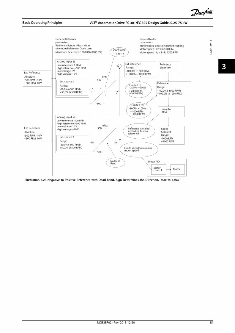
+
500
10V
130B
A18
9.13
-10
-500
-1
500
-500
-10
1 10V
Analog input 53Low reference 0 RPMHigh reference +500 RPMLow voltage 1 VHigh voltage 10 V
Ext. source 1Range:-50,0% (-500 RPM)+50,0% (+500 RPM)
+100,0% (+1000 RPM)
Ext. referenceRange:-100,0% (-1000 RPM)
+500 RPM 10 V
Ext. ReferenceAbsolute-500 RPM -10 V
Referencealgorithm
Reference
+100,0% (+1000 RPM)-100,0% (-1000 RPM)Range:
Limited to:-100%- +100%
(-1000 RPM- +1000 RPM)
Limited to:-200%- +200%(-2000 RPM-+2000 RPM)
Reference is scaled according to max reference
Scale toRPM
+1000 RPM-1000 RPMRange:
Speed Setpoint
Motorcontrol Motor
Limits speed to min max motor speed
Motor PID
RPM
Dead band
General Referenceparameters:Reference Range: -Max - +MaxMinimum Reference: Don't careMaximum Reference: 1000 RPM (100,0%)
General Motorparameters:Motor speed direction: Both directionsMotor speed Low limit: 0 RPMMotor speed high limit: 1500 RPM-1 V to 1 V
RPM
-500 RPM -10 V
Ext. Reference
+500 RPM 10 V
Absolute
+50,0% (+500 RPM)-50,0% (-500 RPM)
High reference +500 RPM
Ext. source 2
Low reference -500 RPMAnalog input 54
Range:
High voltage +10 VLow voltage -10 V
No Dead Band
Illustration 3.23 Negative to Positive Reference with Dead Band, Sign Determines the Direction, -Max to +Max
Basic Operating Principles VLT® AutomationDrive FC 301/FC 302 Design Guide, 0.25-75 kW
MG33BF02 - Rev. 2013-12-20 35
3 3
4 Product Features
4.1 Automated Operational Features
These features are active as soon as the frequencyconverter is operating. They require no programming orset up. Understanding that these features are present canoptimise a system design and possibly avoid introducingredundant components or functionality.
The frequency converter has a range of built-in protectionfunctions to protect itself and the motor it is running.
4.1.1 Short Circuit Protection
Motor (phase-phase)The frequency converter is protected against short circuitson the motor-side by current measurement in each of the3 motor phases or in the DC-link. A short circuit between 2output phases causes an overcurrent in the inverter. Theinverter is turned off when the short circuit currentexceeds the permitted value (Alarm 16 Trip Lock).
Mains sideA frequency converter that works correctly limits thecurrent it can draw from the supply. Still, it isrecommended to use fuses and/or circuit breakers on thesupply side as protection in case of component break-down inside the frequency converter (first fault). Seechapter 9.3 Mains Connection for more information.
NOTICEThis is mandatory to ensure compliance with IEC 60364for CE or NEC 2009 for UL.
Brake resistorThe frequency converter is protected from a short-circuit inthe brake resistor.
Load sharingTo protect the DC bus against short-circuits and thefrequency converters from overload, install DC-fuses inseries with the load sharing terminals of all connectedunits. See chapter 9.6.3 Load Sharing for more information.
4.1.2 Overvoltage Protection
Motor-generated overvoltageThe voltage in the intermediate circuit is increased whenthe motor acts as a generator. This occurs in followingcases:
• The load drives the motor (at constant outputfrequency from the frequency converter), ie. theload generates energy.
• During deceleration (ramp-down) if the momentof inertia is high, the friction is low and the ramp-
down time is too short for the energy to bedissipated as a loss in the frequency converter,the motor and the installation.
• Incorrect slip compensation setting may causehigher DC-link voltage.
• Back-EMF from PM motor operation. If coasted athigh RPM, the PM motor back-EMF maypotentially exceed the maximum voltagetolerance of the frequency converter and causedamage. To help prevent this, the value of4-19 Max Output Frequency is automaticallylimited based on an internal calculation based onthe value of 1-40 Back EMF at 1000 RPM,1-25 Motor Nominal Speed and 1-39 Motor Poles.
NOTICETo avoid that the motor overspeeds (e.g. due toexcessive windmilling effects), equip the frequencyconverter with a brake resistor.
The overvoltage can handled either via using a brakefunction (2-10 Brake Function) and/or using overvoltagecontrol (2-17 Over-voltage Control).
Brake functionsConnect a brake resistor for dissipation of surplus brakeenergy. Connecting a brake resistor allows a higher DC-linkvoltage during braking.
AC brake is an alternative to improve breaking withoutusing a brake resistor. This function controls an over-magnetisation of the motor when running generatoric. Thisfunction can improve the OVC. Increasing the electricallosses in the motor allows the OVC function to increasethe breaking torque without exceeding the overvoltagelimit.
NOTICEAC brake is not as effective as dynamic breaking with aresistor.
Over Voltage Control (OVC)OVC reduces the risk of the frequency converter trippingdue to an overvoltage on the DC-link. This is managed byautomatically extending the ramp-down time.
NOTICEOVC can be activated for PM motor with all control core,PM VVC+, Flux OL and Flux CL for PM Motors.
NOTICEDo not enable OVC in hoisting applications.
Product Features VLT® AutomationDrive FC 301/FC 302 Design Guide, 0.25-75 kW
36 MG33BF02 - Rev. 2013-12-20
44

4.1.3 Missing Motor Phase Detection
The Missing Motor Phase Function (4-58 Missing MotorPhase Function) is enabled by default to avoid motordamage in the case that a motor phase is missing. Thedefault setting is 1,000 ms, but it can be adjusted for afaster detection.
4.1.4 Mains Phase Imbalance Detection
Operation under severe main imbalance conditionsreduces the lifetime of the motor. Conditions areconsidered severe if the motor is operated continuouslynear nominal load. The default setting trips the frequencyconverter in case of mains imbalance (14-12 Function atMains Imbalance).
4.1.5 Switching on the Output
Adding a switch to the output between the motor and thefrequency converter is permitted. Fault messages mayappear. Enable flying start to catch a spinning motor.
4.1.6 Overload Protection
Torque LimitThe torque limit feature protects the motor againstoverload, independent of the speed. Torque limit iscontrolled in 4-16 Torque Limit Motor Mode and or4-17 Torque Limit Generator Mode and the time before thetorque limit warning trips is controlled in 14-25 Trip Delayat Torque Limit.
Current LimitThe current limit is controlled in 4-18 Current Limit and thetime before the frequency converter trips is controlled in14-24 Trip Delay at Current Limit.
Speed LimitMin. speed limit: 4-11 Motor Speed Low Limit [RPM] or4-12 Motor Speed Low Limit [Hz] limit the operating speedrange to for instance between 30 and 50/60Hz.Max. speed limit: (4-13 Motor Speed High Limit [RPM] or4-19 Max Output Frequency limit the max output speed thefrequency converter can provide.
ETRETR is an electronic feature that simulates a bimetal relaybased on internal measurements. The characteristic isshown in Illustration 4.1.
Voltage LimitThe inverter turns off to protect the transistors and theintermediate circuit capacitors when a certain hard-codedvoltage level is reached.
OvertemperatureThe frequency converter has built-in temperature sensorsand reacts immediately to critical values via hard-codedlimits.
4.1.7 Locked Rotor Protection
There may be situations when the rotor is locked due toexcessive load or some other factors (bearing, orapplication create locked rotor situation). This leads tooverheating of motor winding (free movement of rotor isrequired for proper cooling). The frequency converter isable to detect the locked rotor situation with open loopPM flux control, and PM VVC+ control (30-22 Locked RotorProtection).
4.1.8 Automatic Derating
The frequency converter constantly checks for criticallevels:
• Critical high temperature on the control card orheatsink
• High motor load
• High DC-link voltage
• Low motor speed
As a response to a critical level, the frequency converteradjusts the switching frequency. For critical high internaltemperatures and low motor speed, the frequencyconverters can also force the PWM pattern to SFAVM.
NOTICEThe automatic derating is different when 14-55 OutputFilter is set to [2] Sine-Wave Filter Fixed.
4.1.9 Automatic Energy Optimisation
Automatic energy optimisation (AEO), directs the frequencyconverter to continuously monitor the load on the motorand adjust the output voltage to maximise efficiency.Under light load, the voltage is reduced and the motorcurrent is minimised. The motor benefits from increasedefficiency, reduced heating, and quieter operation. There isno need to select a V/Hz curve because the frequencyconverter automatically adjusts motor voltage.
4.1.10 Automatic Switching FrequencyModulation
The frequency converter generates short electrical pulsesto form an AC wave pattern. The carrier frequency is therate of these pulses. A low carrier frequency (slow pulsingrate) causes noise in the motor, making a higher carrierfrequency preferable. A high carrier frequency, however,generates heat in the frequency converter which can limitthe amount of current available to the motor. The use ofinsulated gate bi-polar transistors (IGBT) means very high-speed switching.
Product Features VLT® AutomationDrive FC 301/FC 302 Design Guide, 0.25-75 kW
MG33BF02 - Rev. 2013-12-20 37
4 4
Automatic switching frequency modulation regulates theseconditions automatically to provide the highest carrierfrequency without overheating the frequency converter. Byproviding a regulated high carrier frequency, it quietsmotor operating noise at slow speeds, when audible noisecontrol is critical, and produces full output power to themotor when the demand requires.
4.1.11 Automatic Derating for High CarrierFrequency
The frequency converter is designed for continuous, fullload operation at carrier frequencies between 3.0 and 4.5kHz. A carrier frequency higher than 4.5 kHz generatesincreased heat in the frequency converter and requires theoutput current to be derated.
An automatic feature of the frequency converter is load-dependent carrier frequency control. This feature allowsthe motor to benefit from as high a carrier frequency asthe load permits.
4.1.12 Power Fluctuation Performance
The frequency converter withstands mains fluctuationssuch as transients, momentary dropouts, short voltagedrops and surges. The frequency converter automaticallycompensates for input voltages ±10% from the nominal toprovide full rated motor voltage and torque. With autorestart selected, the frequency converter automaticallypowers up after a voltage trip. And with flying start, thefrequency converter synchronises to motor rotation priorto start.
4.1.13 Resonance Damping
High frequency motor resonance noise can be eliminatedthrough the use of resonance damping. Automatic ormanually selected frequency damping is available.
4.1.14 Temperature-controlled Fans
The internal cooling fans are temperature controlled bysensors in the frequency converter. The cooling fan often isnot running during low load operation or when in sleepmode or standby. This reduces noise, increases efficiency,and extends the operating life of the fan.
4.1.15 EMC Compliance
Electromagnetic interference (EMI) or radio frequencyinterference (RFI, in case of radio frequency) is disturbancewhich can affect an electrical circuit due to electro-magnetic induction or radiation from an external source.The frequency converter is designed to comply with theEMC product standard for drives IEC 61800-3 as well as the
European standard EN 55011. To comply with the emissionlevels in EN 55011, the motor cable must be shielded andproperly terminated. For more information regarding EMCperformance, see chapter 5.2.1 EMC Test Results.
4.1.16 Galvanic Isolation of ControlTerminals
All control terminals and output relay terminals are galvan-ically isolated from mains power. This means the controllercircuitry is completely protected from the input current.The output relay terminals require their own grounding.This isolations meets the stringent protective extra-lowvoltage (PELV) requirements for isolation.
The components that make up the galvanic isolation are
• Power supply, including signal isolation
• Gate drive for the IGBTs, the trigger transformersand optocouplers
• The output current Hall Effect transducers
4.2 Custom Application Features
These are the most common features programmed for usein the frequency converter for enhanced systemperformance. They require minimum programming or setup. Understanding that these features are available canoptimie a system design and possibly avoid introducingredundant components or functionality. See the productspecific Programming Guide, for instructions on activatingthese functions.
4.2.1 Automatic Motor Adaptation
Automatic motor adaptation (AMA) is an automated testprocedure used to measure the electrical characteristics ofthe motor. AMA provides an accurate electronic model ofthe motor. It allows the frequency converter to calculateoptimal performance and efficiency with the motor.Running the AMA procedure also maximises the automaticenergy optimisation feature of the frequency converter.AMA is performed without the motor rotating and withoutuncoupling the load from the motor.
Product Features VLT® AutomationDrive FC 301/FC 302 Design Guide, 0.25-75 kW
38 MG33BF02 - Rev. 2013-12-20
44

4.2.2 Motor Thermal Protection
Motor thermal protection can be provided in 3 ways:
• Via direct temperature sensing via one of thefollowing
- PTC- or KTY sensor in the motorwindings and connected on a standardAI or DI
- PT100 or PT1000 in the motor windingsand motor bearings, connected onSensor Input Card MCB 114
- PTC Thermistor input on PTC ThermistorCard MCB 112 (ATEX approved)
• Mechanical thermal switch (Klixon type) on a DI
• Via the built-in Electronic Thermal Relay (ETR).
ETR calculates motor temperature by measuring current,frequency, and operating time. The frequency converterdisplays the thermal load on the motor in percentage andcan issue a warning at a programmable overload set-point.Programmable options at the overload allow the frequencyconverter to stop the motor, reduce output, or ignore thecondition. Even at low speeds, the frequency convertermeets I2t Class 20 electronic motor overload standards.
1.21.0 1.4
30
1020
10060
4050
1.81.6 2.0
2000
500
200
400300
1000600
t [s]
175Z
A05
2.12
fOUT = 2 x f M,N
fOUT = 0.2 x f M,N
fOUT = 1 x f M,N(par. 1-23)
IMN(par. 1-24)IM
Illustration 4.1 ETR Characteristics
The X-axis shows the ratio between Imotor and Imotor
nominal. The Y-axis shows the time in seconds before theETR cuts off and trips the frequency converter. The curvesshow the characteristic nominal speed, at twice thenominal speed and at 0.2 x the nominal speed.At lower speed, the ETR cuts off at lower heat due to lesscooling of the motor. In that way, the motor is protectedfrom being overheated even at low speed. The ETR featureis calculating the motor temperature based on actualcurrent and speed. The calculated temperature is visible asa read-out parameter in 16-18 Motor Thermal.
A special version of the ETR is also available for EX-emotors in ATEX areas. This function makes it possible toenter a specific curve to protect the Ex-e motor. TheProgramming Guide takes the user through the set-up.
4.2.3 Mains Drop-out
During a mains drop-out, the frequency converter keepsrunning until the intermediate circuit voltage drops belowthe minimum stop level, which is typically 15% below thefrequency converter's lowest rated supply voltage. Themains voltage before the drop-out and the motor loaddetermines how long it takes for the frequency converterto coast.
The frequency converter can be configured (14-10 MainsFailure) to different types of behaviour during mains drop-out, e.g:
• Trip Lock once the DC-link is exhausted
• Coast with flying start whenever mains return(1-73 Flying Start)
• Kinetic back-up
• Controlled ramp-down
Flying startThis selection makes it possible to catch a motor that isspinning freely due to a mains drop-out. This option isvery relevant for centrifuges and fans.
Kinetic back-upThis selection ensures that the frequency converter runs aslong as there is energy in the system. For short mainsdrop-out the operation is restored upon mains return,without bringing the application to a stop or loosingcontrol at any time. Several variants of kinetic back-up canbe selected.
The behaviour of the frequency converter at mains drop-out can be configured in 14-10 Mains Failure and1-73 Flying Start.
4.2.4 Built-in PID Controller
The built-in proportional, integral, derivative (PID)controller is available, eliminating the need for auxiliarycontrol devices. The PID controller maintains constantcontrol of closed loop systems where regulated pressure,flow, temperature, or other system requirements must bemaintained. The frequency converter can provide self-reliant control the motor speed in response to feedbacksignals from remote sensors.
The frequency converter accommodates 2 feedback signalsfrom 2 different devices. This feature allows regulating asystem with different feedback requirements. The
Product Features VLT® AutomationDrive FC 301/FC 302 Design Guide, 0.25-75 kW
MG33BF02 - Rev. 2013-12-20 39
4 4
frequency converter makes control decisions by comparingthe two signals to optimise system performance.
4.2.5 Automatic Restart
The frequency converter can be programmed to automat-ically restart the motor after a minor trip, such asmomentary power loss or fluctuation. This featureeliminates the need for manual resetting and enhancesautomated operation for remotely controlled systems. Thenumber of restart attempts as well as the durationbetween attempts can be limited.
4.2.6 Flying Start
Flying start allows the frequency converter to synchronisewith an operating motor rotating at up to full speed, ineither direction. This prevents trips due to overcurrentdraw. It minimises mechanical stress to the system sincethe motor receives no abrupt change in speed when thefrequency converter starts.
4.2.7 Full Torque at Reduced Speed
The frequency converter follows a variable V/Hz curve toprovide full motor torque even at reduced speeds. Fulloutput torque can coincide with the maximum designedoperating speed of the motor. This is unlike variabletorque converters that provide reduced motor torque atlow speed, or constant torque converters that provideexcess voltage, heat and motor noise at less than fullspeed.
4.2.8 Frequency Bypass
In some applications, the system may have operationalspeeds that create a mechanical resonance. This cangenerate excessive noise and possibly damage mechanicalcomponents in the system. The frequency converter has 4programmable bypass-frequency bandwidths. These allowthe motor to step over speeds which induce systemresonance.
4.2.9 Motor Preheat
To preheat a motor in a cold or damp environment, asmall amount of DC current can be trickled continuouslyinto the motor to protect it from condensation and a coldstart. This can eliminate the need for a space heater.
4.2.10 4 Programmable Set-ups
The frequency converter has 4 set-ups which can beindependently programmed. Using multi-setup, it ispossible to switch between independently programmed
functions activated by digital inputs or a serial command.Independent set-ups are used, for example, to changereferences, or for day/night or summer/winter operation, orto control multiple motors. The active set-up is displayedon the LCP.
Set-up data can be copied from frequency converter tofrequency converter by downloading the information fromthe removable LCP.
4.2.11 Dynamic Braking
Dynamic Brake is established by:
• Resistor brakeA brake IGBT keeps the overvoltage under acertain threshold by directing the brake energyfrom the motor to the connected brake resistor(2-10 Brake Function = [1]).
• AC brakeThe brake energy is distributed in the motor bychanging the loss conditions in the motor. TheAC brake function cannot be used in applicationswith high cycling frequency since this overheatsthe motor (2-10 Brake Function = [2]).
• DC brakeAn over-modulated DC current added to the ACcurrent works as an eddy current brake (2-02 DCBraking Time ≠ 0 s ).
4.2.12 Open Loop Mechanical BrakeControl
Parameters for controlling operation of an electro-magnetic (mechanical) brake, typically required in hoistingapplications.To control a mechanical brake, a relay output (relay 01 orrelay 02) or a programmed digital output (terminal 27 or29) is required. Normally, this output must be closedduring periods when the frequency converter is unable to‘hold’ the motor, e.g. due to an excessive load. Select [32]Mechanical Brake Control for applications with an electro-magnetic brake in 5-40 Function Relay, 5-30 Terminal 27Digital Output, or 5-31 Terminal 29 Digital Output. Whenselecting [32] Mechanical brake control, the mechanicalbrake is closed from start up until the output current isabove the level selected in 2-20 Release Brake Current.During stop, the mechanical brake activates when thespeed drops below the level specified in 2-21 ActivateBrake Speed [RPM]. If the frequency converter enters analarm condition or an overcurrent or overvoltage situation,the mechanical brake immediately cuts in. This is also thecase during Safe Torque Off.
Product Features VLT® AutomationDrive FC 301/FC 302 Design Guide, 0.25-75 kW
40 MG33BF02 - Rev. 2013-12-20
44
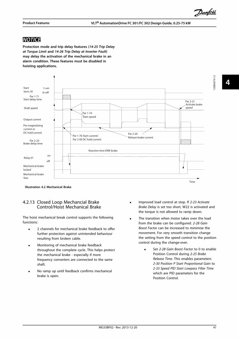
NOTICEProtection mode and trip delay features (14-25 Trip Delayat Torque Limit and 14-26 Trip Delay at Inverter Fault)may delay the activation of the mechanical brake in analarm condition. These features must be disabled inhoisting applications.
Startterm.18
1=on
0=o
Shaft speed
Start delay time
on
o
Brake delay time
Time
Output current
Relay 01
Pre-magnetizingcurrent orDC hold current
Reaction time EMK brake
Par 2-20Release brake currentPar 1-76 Start current/
Par 2-00 DC hold current
Par 1-74Start speed
Par 2-21Activate brake speed
Mechanical brakelocked
Mechanical brakefree
Par 1-71
Par 2-23
130B
A07
4.12
Illustration 4.2 Mechanical Brake
4.2.13 Closed Loop Mechancial BrakeControl/Hoist Mechanical Brake
The hoist mechanical break control supports the followingfunctions:
• 2 channels for mechanical brake feedback to offerfurther protection against unintended behaviourresulting from broken cable.
• Monitoring of mechanical brake feedbackthroughout the complete cycle. This helps protectthe mechanical brake - especially if morefrequency converters are connected to the sameshaft.
• No ramp up until feedback confirms mechanicalbrake is open.
• Improved load control at stop. If 2-23 ActivateBrake Delay is set too short, W22 is activated andthe torque is not allowed to ramp down.
• The transition when motor takes over the loadfrom the brake can be configured. 2-28 GainBoost Factor can be increased to minimise themovement. For very smooth transition changethe setting from the speed control to the positioncontrol during the change-over.
• Set 2-28 Gain Boost Factor to 0 to enablePosition Control during 2-25 BrakeRelease Time. This enables parameters2-30 Position P Start Proportional Gain to2-33 Speed PID Start Lowpass Filter Timewhich are PID parameters for thePosition Control.
Product Features VLT® AutomationDrive FC 301/FC 302 Design Guide, 0.25-75 kW
MG33BF02 - Rev. 2013-12-20 41
4 4

130B
A64
2.12
A22Active
W22Active W22
Active
A22Active
High
Low
High
Low
Open
Closed
MotorSpeed
TorqueRef.
BrakeRelay
Mech BrakeFeedback
Gain Boost orPostion Control
Mech BrakePosition
Activate BrakeDelayP. 2-23
Torque RampDown Time
p. 2-29
Stop DelayP. 2-24
Ramp 1 DownP. 3-42
Ramp 1 UpP. 3-41
Brake ReleaseTime
p. 2-25
Torque RampUp Timep. 2-27
Contact no.2OPTIONALE.g. DI33 [71] Mech. Brake Feedback
Contact no.1E.g. DI32 [70] Mech. Brake Feedback
Gain Boost. p. 2-28
Torque Ref. p. 2-26
Illustration 4.3 Brake release sequence for hoist mechanical brake control. This brake control is available in FLUX with motorfeedback only, available for asynchronous and non-salient PM motors.
2-26 Torque Ref to 2-33 Speed PID Start Lowpass Filter Timeare only available for the hoist mechanical brake control(FLUX with motor feedback). 2-30 Position P Start Propor-tional Gain to 2-33 Speed PID Start Lowpass Filter Time canbe set up for very smooth transition change from speedcontrol to position control during 2-25 Brake Release Time -the time when the load is transferred from the mechanicalbrake to the frequency converter.2-30 Position P Start Proportional Gain to 2-33 Speed PIDStart Lowpass Filter Time are activated when 2-28 GainBoost Factor is set to 0. See Illustration 4.3 for moreinformation.
NOTICEFor an example of advanced mechanical brake controlfor hoisting applications, see chapter 10 ApplicationExamples.
Product Features VLT® AutomationDrive FC 301/FC 302 Design Guide, 0.25-75 kW
42 MG33BF02 - Rev. 2013-12-20
44

4.2.14 Smart Logic Control (SLC)
Smart Logic Control (SLC) is a sequence of user-definedactions (see 13-52 SL Controller Action [x]) executed by theSLC when the associated user defined event (see 13-51 SLController Event [x]) is evaluated as TRUE by the SLC.The condition for an event can be a particular status orthat the output from a Logic Rule or a ComparatorOperand becomes TRUE. That leads to an associatedAction as shown in Illustration 4.4.
. . .
. . .
Par. 13-11Comparator Operator
Par. 13-43Logic Rule Operator 2
Par. 13-51SL Controller Event
Par. 13-52SL Controller Action
130B
B671
.13
CoastStart timerSet Do X lowSelect set-up 2. . .
RunningWarningTorque limitDigital input X 30/2. . .
=TRUE longer than..
. . .
. . .
Illustration 4.4 SCL Event and Action
Events and actions are each numbered and linked in pairs(states). This means that when event [0] is fulfilled (attainsthe value TRUE), action [0] is executed. After this, theconditions of event [1] is evaluated and if evaluated TRUE,action [1] is executed and so on. Only one event isevaluated at any time. If an event is evaluated as FALSE,nothing happens (in the SLC) during the current scaninterval and no other events are evaluated. This means thatwhen the SLC starts, it evaluates event [0] (and only event[0]) each scan interval. Only when event [0] is evaluatedTRUE, the SLC executes action [0] and starts evaluatingevent [1]. It is possible to programme from 1 to 20 eventsand actions.When the last event/action has been executed, thesequence starts over again from event [0]/action [0].Illustration 4.5 shows an example with 4 event/actions:
130B
A06
2.14
State 113-51.013-52.0 State 2
13-51.113-52.1
Startevent P13-01
State 313-51.213-52.2
State 413-51.313-52.3
Stopevent P13-02
Stopevent P13-02
Stopevent P13-02
Illustration 4.5 Order of Execution when 4 Events/Actions areProgrammed
ComparatorsComparators are used for comparing continuous variables(i.e. output frequency, output current, analog input etc.) tofixed preset values.
Par. 13-11Comparator Operator
=
TRUE longer than.
. . .
. . .
Par. 13-10Comparator Operand
Par. 13-12Comparator Value
130B
B672
.10
Illustration 4.6 Comparators
Logic RulesCombine up to 3 boolean inputs (TRUE/FALSE inputs) fromtimers, comparators, digital inputs, status bits and eventsusing the logical operators AND, OR, and NOT.
. . .
. . . . . .. . .
Par. 13-43Logic Rule Operator 2
Par. 13-41Logic Rule Operator 1
Par. 13-40Logic Rule Boolean 1
Par. 13-42Logic Rule Boolean 2
Par. 13-44Logic Rule Boolean 3
130B
B673
.10
Illustration 4.7 Logic Rules
4.2.15 Safe Torque Off
For information about Safe Torque Off, refer to the VLT® FCSeries Safe Torque Off Operating Instructions.
Product Features VLT® AutomationDrive FC 301/FC 302 Design Guide, 0.25-75 kW
MG33BF02 - Rev. 2013-12-20 43
4 4
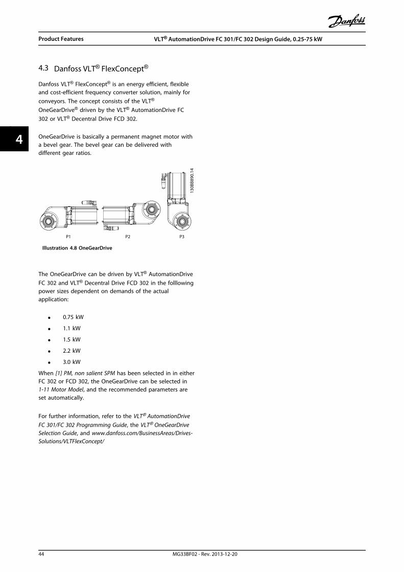
4.3 Danfoss VLT® FlexConcept®
Danfoss VLT® FlexConcept® is an energy efficient, flexibleand cost-efficient frequency converter solution, mainly forconveyors. The concept consists of the VLT®
OneGearDrive® driven by the VLT® AutomationDrive FC302 or VLT® Decentral Drive FCD 302.
OneGearDrive is basically a permanent magnet motor witha bevel gear. The bevel gear can be delivered withdifferent gear ratios.
130B
B890
.14
P1 P2 P3
Illustration 4.8 OneGearDrive
The OneGearDrive can be driven by VLT® AutomationDriveFC 302 and VLT® Decentral Drive FCD 302 in the folllowingpower sizes dependent on demands of the actualapplication:
• 0.75 kW
• 1.1 kW
• 1.5 kW
• 2.2 kW
• 3.0 kW
When [1] PM, non salient SPM has been selected in in eitherFC 302 or FCD 302, the OneGearDrive can be selected in1-11 Motor Model, and the recommended parameters areset automatically.
For further information, refer to the VLT® AutomationDriveFC 301/FC 302 Programming Guide, the VLT® OneGearDriveSelection Guide, and www.danfoss.com/BusinessAreas/Drives-Solutions/VLTFlexConcept/
Product Features VLT® AutomationDrive FC 301/FC 302 Design Guide, 0.25-75 kW
44 MG33BF02 - Rev. 2013-12-20
44
5 System Integration
5.1 Ambient Operating Conditions
5.1.1 Humidity
Although the frequency converter can operate properly athigh humidity (up to 95% relative humidity), condensationmust always be avoided. There is a specific risk of conden-sation when the frequency converter is colder than moistambient air. Moisture in the air can also condense on theelectronic components and cause short circuits. Conden-sation occurs to units without power. It is advisable toinstall a cabinet heater when condensation is possible dueto ambient conditions. Avoid installation in areas subjectto frost.
Alternatively, operating the frequency converter in stand-by mode (with the unit connected to the mains) reducesthe risk of condensation. However, ensure the powerdissipation is sufficient to keep the frequency convertercircuitry free of moisture.
5.1.2 Temperature
Minimum and maximum ambient temperature limits arespecified for all frequency converters. Avoiding extremeambient temperatures prolongs the life of the equipmentand maximises overall system reliability. Follow therecommendations listed for maximum performance andequipment longevity.
• Although converters can operate at temperaturesdown to -10 °C, proper operation at rated load isonly guaranteed at 0 °C or higher.
• Do not exceed the maximum temperature limit.
• The lifetime of electronic components decreasesby 50% for every 10 °C when operated above itsdesign temperature.
• Even devices with IP54, IP55, or IP66 protectionratings must adhere to the specified ambienttemperature ranges.
• Additional air conditioning of the cabinet orinstallation site may be required.
5.1.3 Temperature and Cooling
The frequency converters have built-in fans to ensureoptimum cooling. The main fan forces the air flow alongthe cooling fins on the heat sink, ensuring a cooling of theinternal air. Some power sizes have a small secundary fanclose to the control card, ensuring that the internal air is
circulated to avoid hot spots. The main fan is controlled bythe internal temperature in the frequency converter andthe speed gradually increases along with temperature,reducing noise and energy consumption when the need islow, and ensuring maximum cooling when the need isthere. The fan control can be adapted via 14-52 Fan Controlto accommodate any application, also to protect againstnegative effets of cooling in very cold climates. In case ofover-temperature inside the frequency converter, it deratesthe switching frequency and –pattern, seechapter 5.1.4 Manual Derating for more info.
Minimum and maximum ambient temperature limits arespecified for all frequency converters. Avoiding extremeambient temperatures prolongs the life of the equipmentand maximizes overall system reliability. Follow therecommendations listed for maximum performance andequipment longevity.
• Although frequency converters can operate attemperatures down to -10 °C, proper operation atrated load is only guaranteed at 0 °C or higher.
• Do not exceed the maximum temperature limit.
• Do not exceed the maximum 24h averagetemperatue.(The 24h average temperature is the max.ambient temperature minus 5 °C.Example: Max. temperature is 50 °C, maximum24h avg. temperature is 45 °C )
• Observe the minimum top and bottom clearancerequirements (chapter 8.2.1.1 Clearance).
• As a rule of thumb, the lifetime of electroniccomponents decreases by 50% for every 10 Cwhen operated above its design temperature.
• Even devices with high protection ratings mustadhere to the specified ambient temperatureranges.
• Additional air conditioning of the cabinet orinstallation site may be required.
5.1.4 Manual Derating
Consider derating when any of the following conditionsare present.
• Operating above 1000 m (low air pressure)
• Low speed operation
• Long motor cables
• Cables with a large cross section
System Integration VLT® AutomationDrive FC 301/FC 302 Design Guide, 0.25-75 kW
MG33BF02 - Rev. 2013-12-20 45
5 5
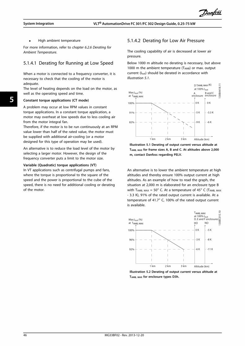
• High ambient temperature
For more information, refer to chapter 6.2.6 Derating forAmbient Temperature.
5.1.4.1 Derating for Running at Low Speed
When a motor is connected to a frequency converter, it isnecessary to check that the cooling of the motor isadequate.The level of heating depends on the load on the motor, aswell as the operating speed and time.
Constant torque applications (CT mode)
A problem may occur at low RPM values in constanttorque applications. In a constant torque application, amotor may overheat at low speeds due to less cooling airfrom the motor integral fan.Therefore, if the motor is to be run continuously at an RPMvalue lower than half of the rated value, the motor mustbe supplied with additional air-cooling (or a motordesigned for this type of operation may be used).
An alternative is to reduce the load level of the motor byselecting a larger motor. However, the design of thefrequency converter puts a limit to the motor size.
Variable (Quadratic) torque applications (VT)In VT applications such as centrifugal pumps and fans,where the torque is proportional to the square of thespeed and the power is proportional to the cube of thespeed, there is no need for additional cooling or deratingof the motor.
5.1.4.2 Derating for Low Air Pressure
The cooling capability of air is decreased at lower airpressure.
Below 1000 m altitude no derating is necessary, but above1000 m the ambient temperature (TAMB) or max. outputcurrent (Iout) should be derated in accordance withIllustration 5.1.
Max.Iout (%)at TAMB, MAX
A
Altitude (km)
enclosureB and Cenclosure
Tat 100% Iout
D
100%
91%
82%
0 K
-5 K
-9 K
1 km 2 km 3 km
0 K
-3.3 K
-6 K
130B
A41
8.11AMB, MAX (K)
Illustration 5.1 Derating of output current versus altitude atTAMB, MAX for frame sizes A, B and C. At altitudes above 2,000
m, contact Danfoss regarding PELV.
An alternative is to lower the ambient temperature at highaltitudes and thereby ensure 100% output current at highaltitudes. As an example of how to read the graph, thesituation at 2,000 m is elaborated for an enclosure type Bwith TAMB, MAX = 50° C. At a temperature of 45° C (TAMB, MAX
- 3.3 K), 91% of the rated output current is available. At atemperature of 41.7° C, 100% of the rated output currentis available.
Max.Iout (%)at TAMB, MAX
D, E and F enclosures
Altitude (km)
HO NO
Tat 100% Iout
100%
96%
92%
0 K
-3 K
-6 K
1 km 2 km 3 km
-5 K
-8 K
-11 K
130B
C01
5.10AMB, MAX
Illustration 5.2 Derating of output current versus altitude atTAMB, MAX for enclosure types D3h.
System Integration VLT® AutomationDrive FC 301/FC 302 Design Guide, 0.25-75 kW
46 MG33BF02 - Rev. 2013-12-20
55

5.1.5 Acoustic Noise
Acoustic noise from the frequency converter comes from 3sources
• DC-link (intermediate circuit) coils
• RFI filter choke
• Internal fans
See chapter 6.2.9 Acoustic Noise for acoustic noise ratings.
5.1.6 Vibration and Shock
The frequency converter tested according to a procedurebased on the IEC 68-2-6/34/35 and 36. These tests subjectthe unit to 0.7 g forces, over the range of 18 to 1,000 Hzrandom, in 3 directions for 2 hours. All Danfoss frequencyconverters comply with requirements that correspond tothese conditions when the unit is wall or floor mounted, aswell as when mounted within panels bolted to walls orfloors.
5.1.7 Aggressive Atmospheres
5.1.7.1 Gases
Aggressive gases, such as hydrogen sulphide, chlorine, or ammonia can damage frequency converter electrical andmechanical components. Contamination of the cooling air can also cause the gradual decomposition of PCB tracks and doorseals. Aggressive contaminants are often present in sewage treatment plants or swimming pools. A clear sign of anaggressive atmosphere is corroded copper.
In aggressive atmospheres, restricted IP enclosures are recommended along with conformal-coated circuit boards. SeeTable 5.1 for conformal-coating values.
NOTICEThe frequency converter comes standard with class 3C2 coating. On request, class 3C3 coating is available.
Gas type Unit
Class
3C1 3C2 3C3
Average value Max. value Average value Max. value
Sea salt n/a None Salt mist Salt mist
Sulphur oxides mg/m3 0.1 0.3 1.0 5.0 10
Hydrogen sulphide mg/m3 0.01 0.1 0.5 3.0 10
Chlorine mg/m3 0.01 0.1 0.03 0.3 1.0
Hydrogen chloride mg/m3 0.01 0.1 0.5 1.0 5.0
Hydrogen fluoride mg/m3 0.003 0.01 0.03 0.1 3.0
Ammonia mg/m3 0.3 1.0 3.0 10 35
Ozone mg/m3 0.01 0.05 0.1 0.1 0.3
Nitrogen mg/m3 0.1 0.5 1.0 3.0 9.0
Table 5.1 Conformal-coating Class Ratings
Maximum values are transient peak values not to exceed 30 minutes per day.
5.1.7.2 Dust Exposure
Installation of frequency converters in environments withhigh dust exposure is often unavoidable. Dust affects wallor frame mounted units with IP55 or IP66 protectionrating, and also cabinet mounted devices with IP21 or IP20protection rating. Take the 3 aspects described below intoaccount when frequency converters are installed in suchenvironments.
Reduced CoolingDust forms deposits on the surface of the device andinside on circuit boards and the electronic components.These deposits act as insulation layers and hamper heattransfer to the ambient air, reducing the cooling capacity.
The components become warmer. This causes acceleratedaging of the electronic components, and the service life ofthe unit decreases. Dust deposits on the heat sink in theback of the unit also decrease the service life of the unit.
Cooling FansThe airflow for cooling the unit is produced by coolingfans, usually located on the back of the device. The fanrotors have small bearings into which dust can penetrateand act as an abrasive. This leads to bearing damage andfan failure.
FiltersHigh-power frequency converters are equipped withcooling fans that expel hot air from the interior of the
System Integration VLT® AutomationDrive FC 301/FC 302 Design Guide, 0.25-75 kW
MG33BF02 - Rev. 2013-12-20 47
5 5

device. Above a certain size, these fans are fitted with filtermats. These filters can become quickly clogged when usedin very dusty environments. Preventative measures arenecessary under these conditions.
Periodic Maintenance
Under the conditions described above, it is advisable toclean the frequency converter during periodicmaintenance. Remove dust off the heat sink and fans andclean the filter mats.
5.1.7.3 Potentially Explosive Atmospheres
Systems operated in potentially explosive atmospheresmust fulfil special conditions. EU Directive 94/9/ECdescribes the operation of electronic devices in potentiallyexplosive atmospheres.
Motors controlled by frequency converters in potentiallyexplosive atmospheres must be monitored for temperatureusing a PTC temperature sensor. Motors with ignitionprotection class d or e are approved for this environment.
• e classification consists of preventing anyoccurrence of a spark. The FC 302 with firmwareversion V6.3x or higher is equipped with an"ATEX ETR thermal monitoring" function foroperation of specially approved Ex-e motors.When combined with an ATEX approved PTCmonitoring device like the PTC Thermistor CardMCB 112 the installation does not need anindividual approval from an approbated organi-sation, i.e. no need for matched pairs.
• d classification consists of ensuring that if a sparkoccurs, it is contained in a protected area. Whilenot requiring approval, special wiring andcontainment are required.
• d/e combination is the most often used inpotentially explosive atmospheres. The motoritself has a e ignition protection class, while themotor cabling and connection environment is incompliance with the e classification. Therestriction on the e connection space consists ofthe maximum voltage allowed in this space. Theoutput voltage of a frequency converter is usuallylimited to the mains voltage. The modulation ofthe output voltage may generate unallowablehigh peak voltage for e classification. In practice,using a sine-wave filter at the frequencyconverter output has proven to be an effectivemeans to attenuate the high peak voltage.
NOTICEDo not install a frequency converter in a potentiallyexplosive atmosphere. Install the frequency converter ina cabinet outside of this area. Using a sine-wave filter atthe output of the frequency converter is alsorecommended to attenuate the dU/dt voltage rise andpeak voltage. Keep the motor cables as short as possible.
NOTICEVLT® AutomationDrive units with the MCB 112 optionhave PTB-certified motor thermistor sensor monitoringcapability for potentially explosive atmospheres.Shielded motor cables are not necessary when frequencyconverters are operated with sine-wave output filters.
5.1.8 Maintenance
Danfoss frequency converter models up to 90 kW aremaintenance free. High power frequency converters (ratedat 110 kW or higher) have built-in filter mats which requireperiodic cleaning by the operator, depending on theexposure to dust and contaminants. Maintenance intervalsfor the cooling fans (approximately 3 years) and capacitors(approximately 5 years) are recommended in mostenvironments.
5.1.9 Storage
Like all electronic equipment, frequency converters mustbe stored in a dry location. Periodic forming (capacitorcharging) is not necessary during storage.
It is recommended to keep the equipment sealed in itspackaging until installation.
System Integration VLT® AutomationDrive FC 301/FC 302 Design Guide, 0.25-75 kW
48 MG33BF02 - Rev. 2013-12-20
55

5.2 General Aspects of EMC
Electrical interference is usually conducted at frequencies in the range 150 kHz to 30 MHz. Airborne interference from thefrequency converter system in the range 30 MHz to 1 GHz is generated from the inverter, motor cable, and the motor.As shown in Illustration 5.3, capacitance in the motor cable coupled with a high dU/dt from the motor voltage generateleakage currents.The use of a screened motor cable increases the leakage current (see Illustration 5.3) because screened cables have highercapacitance to ground than unscreened cables. If the leakage current is not filtered, it causes greater interference on themains in the radio frequency range below approximately 5 MHz. Since the leakage current (I1) is carried back to the unitthrough the screen (I3), there is in principle only a small electro-magnetic field (I4) from the screened motor cable accordingto Illustration 5.3.
The screen reduces the radiated interference, but increases the low-frequency interference on the mains. Connect the motorcable screen to the frequency converter enclosure as well as on the motor enclosure. This is best done by using integratedscreen clamps so as to avoid twisted screen ends (pigtails). Pigtails increase the screen impedance at higher frequencies,which reduces the screen effect and increases the leakage current (I4).If a screened cable is used for relay, control cable, signal interface and brake, mount the screen on the enclosure at bothends. In some situations, however, it is necessary to break the screen to avoid current loops.
1
2
z
z
z
L1
L2
L3
PE
U
V
W
CS
I2
I1
I3
I4
CS CS CS
CS
I4
CSz PE
3 4 5 6
175Z
A06
2.12
1 Ground wire 4 Frequency converter
2 Screen 5 Screened motor cable
3 AC mains supply 6 Motor
Illustration 5.3 Situation that Generates Leakage Currents
If the screen is to be placed on a mounting plate for the frequency converter, the mounting plate must be made of metal,to convey the screen currents back to the unit. Moreover, ensure good electrical contact from the mounting plate throughthe mounting screws to the frequency converter chassis.
When unscreened cables are used, some emission requirements are not complied with, although most immunityrequirements are observed.
To reduce the interference level from the entire system (unit+installation), make motor and brake cables as short aspossible. Avoid placing cables with a sensitive signal level alongside motor and brake cables. Radio interference higher than50 MHz (airborne) is especially generated by the control electronics.
System Integration VLT® AutomationDrive FC 301/FC 302 Design Guide, 0.25-75 kW
MG33BF02 - Rev. 2013-12-20 49
5 5

5.2.1 EMC Test Results
The following test results have been obtained using a system with a frequency converter, a screened control cable, a controlbox with potentiometer, as well as a single motor and screened motor cable (Ölflex Classic 100 CY) at nominal switchingfrequency. Table 5.2 states the maximum motor cable lengths for compliance.
NOTICEConditions may change significantly for other set-ups.
NOTICEConsult Table 9.19 for parallel motor cables.
RFI filter type Conducted emission Radiated emission
Cable length [m]
Standards andrequirements
EN 55011/CISPR 11 Class B Class AGroup 1
Class AGroup 2
Class B Class AGroup 1
Class AGroup 2
EN/IEC 61800-3 Category C1 Category C2 Category C3 Category C1 Category C2 Category C3
H1
FC 301 0-37 kW 200-240 V 10 50 50 No Yes Yes
0-75 kW 380-480 V 10 50 50 No Yes Yes
FC 302 0-37 kW 200-240 V 50 150 150 No Yes Yes
0-75 kW 380-480 V 50 150 150 No Yes Yes
H2/H5
FC 301 0-3.7 kW 200-240 V No No 5 No No Yes
FC 302 5.5-37 kW 200-240 V2) No No 25 No No Yes
0-7.5 kW 380-500 V No No 5 No No Yes
11-75 kW 380-500 V2) No No 25 No No Yes
11-22 kW 525-690 V2) No No 25 No No Yes
30-75 kW 525-690 V2) No No 25 No No Yes
H3
FC 301 0-1.5 kW 200-240V 2.5 25 25 No Yes Yes
0-1.5 kW 380-480V 2.5 25 25 No Yes Yes
H4
FC 302 1.1-7.5 kW 525-690 V No 100 100 No Yes Yes
11-22 kW 525-690 V No 100 100 No Yes Yes
11-37 kW 525-690 V3 No 150 150 No Yes Yes
30-75 kW 525-690 V No 150 150 No Yes Yes
Hx1)
FC 302 0.75-75 kW 525-600 V No No No No No No
Table 5.2 EMC Test Results (Emission) Maximum Motor Cable Length
1) Hx versions can be used according to EN/IEC 61800-3 category C42) T5, 22-45 kW and T7, 22-75 kW comply with class A group 1 with 25 m motor cable. Some restrictions for the installation apply (contactDanfoss for details).Hx, H1, H2, H3, H4 or H5 is defined in the type code pos. 16-17 for EMC filters, see Table 7.1.3) IP20
System Integration VLT® AutomationDrive FC 301/FC 302 Design Guide, 0.25-75 kW
50 MG33BF02 - Rev. 2013-12-20
55

5.2.2 Emission Requirements
The EMC product standard for frequency convertersdefines 4 categories (C1, C2, C3 and C4) with specifiedrequirements for emission and immunity. Table 5.3 statesthe definition of the 4 categories and the equivalent classi-fication from EN 55011.
Category Definition
Equivalentemissionclass in EN55011
C1 Frequency converters installed inthe first environment (home andoffice) with a supply voltage lessthan 1000 V.
Class B
C2 Frequency converters installed inthe first environment (home andoffice) with a supply voltage lessthan 1000 V, which are neitherplug-in nor movable and areintended to be installed andcommissioned by a professional.
Class A Group 1
C3 Frequency converters installed inthe second environment(industrial) with a supply voltagelower than 1000 V.
Class A Group 2
C4 Frequency converters installed inthe second environment with asupply voltage equal to or above1000 V or rated current equal to orabove 400 A or intended for use incomplex systems.
No limit line.An EMC planshould bemade.
Table 5.3 Correlation between IEC 61800-3 and EN 55011
When the generic (conducted) emission standards areused, the frequency converters are required to complywith the limits in Table 5.4.
EnvironmentGeneric emissionstandard
Equivalentemission classin EN 55011
Firstenvironment(home andoffice)
EN/IEC 61000-6-3 Emissionstandard for residential,commercial and lightindustrial environments.
Class B
Secondenvironment(industrialenvironment)
EN/IEC 61000-6-4 Emissionstandard for industrialenvironments.
Class A Group 1
Table 5.4 Correlation between Generic Emission Standards andEN 55011
5.2.3 Immunity Requirements
The immunity requirements for frequency convertersdepend on the environment where they are installed. Therequirements for the industrial environment are higherthan the requirements for the home and officeenvironment. All Danfoss frequency converters complywith the requirements for the industrial environment andconsequently comply also with the lower requirements forhome and office environment with a large safety margin.
To document immunity against electrical interference fromelectrical phenomena, the following immunity tests havebeen made in accordance with following basic standards:
• EN 61000-4-2 (IEC 61000-4-2): Electrostaticdischarges (ESD): Simulation of electrostaticdischarges from human beings.
• EN 61000-4-3 (IEC 61000-4-3): Incoming electro-magnetic field radiation, amplitude modulatedsimulation of the effects of radar and radiocommunication equipment as well as mobilecommunications equipment.
• EN 61000-4-4 (IEC 61000-4-4): Burst transients:Simulation of interference brought about byswitching a contactor, relay or similar devices.
• EN 61000-4-5 (IEC 61000-4-5): Surge transients:Simulation of transients brought about e.g. bylightning that strikes near installations.
• EN 61000-4-6 (IEC 61000-4-6): RF Commonmode: Simulation of the effect from radio-transmission equipment joined by connectioncables.
See Table 5.5.
System Integration VLT® AutomationDrive FC 301/FC 302 Design Guide, 0.25-75 kW
MG33BF02 - Rev. 2013-12-20 51
5 5

Basic standard BurstIEC 61000-4-4
SurgeIEC 61000-4-5
ESDIEC
61000-4-2
Radiated electromagneticfield
IEC 61000-4-3
RF commonmode voltageIEC 61000-4-6
Acceptance criterion B B B A AVoltage range: 200-240 V, 380-500 V, 525-600 V, 525-690 VLine
4 kV CM2 kV/2 Ω DM
4 kV/12 Ω CM— — 10 VRMS
Motor 4 kV CM 4 kV/2 Ω 1) — — 10 VRMS
Brake 4 kV CM 4 kV/2 Ω 1) — — 10 VRMS
Load sharing 4 kV CM 4 kV/2 Ω 1) — — 10 VRMS
Control wires 2 kV CM 2 kV/2 Ω 1) — — 10 VRMS
Standard bus 2 kV CM 2 kV/2 Ω 1) — — 10 VRMS
Relay wires 2 kV CM 2 kV/2 Ω 1) — — 10 VRMS
Application and Fieldbusoptions
2 kV CM2 kV/2 Ω 1) — — 10 VRMS
LCP cable 2 kV CM 2 kV/2 Ω 1) — — 10 VRMS
External 24 V DC2 V CM
0.5 kV/2 Ω DM1 kV/12 Ω CM
— — 10 VRMS
Enclosure— —
8 kV AD6 kV CD
10V/m —
Table 5.5 EMC Immunity Form
1) Injection on cable shield
5.2.4 Motor Insulation
Modern design of motors for use with frequencyconverters have a high degree of insulation to account fornew generation high-efficiency IGBTs with high dU/dt. Forretrofit in old motors it is necessary to confirm the motorinsulation or to mitigate with dU/dt filter or if necessary asine-wave filter. dU/dt
For motor cable lengths ≤ the maximum cable lengthlisted in chapter 6.2 General Specifications, the motorinsulation ratings listed in Table 5.6 are recommended. If amotor has lower insulation rating, it is recommended touse a dU/dt or sine-wave filter.
Nominal Mains Voltage [V] Motor Insulation [V]
UN ≤ 420 Standard ULL = 1300
420 V < UN ≤ 500 Reinforced ULL = 1600
500 V < UN ≤ 600 Reinforced ULL = 1800
600 V < UN ≤ 690 Reinforced ULL = 2000
Table 5.6 Motor Insulation
5.2.5 Motor Bearing Currents
To minimise bearing and shaft currents, ground thefollowing to the driven machine:
• frequency converter
• motor
• driven machine
• motor
Standard Mitigation Strategies1. Use an insulated bearing.
2. Apply rigorous installation procedures
2a Ensure the motor and load motor arealigned.
2b Strictly follow the EMC Installationguideline.
2c Reinforce the PE so the high frequencyimpedance is lower in the PE than theinput power leads.
2d Provide a good high frequencyconnection between the motor and thefrequency converter for instance byscreened cable which has a 360°connection in the motor and thefrequency converter.
System Integration VLT® AutomationDrive FC 301/FC 302 Design Guide, 0.25-75 kW
52 MG33BF02 - Rev. 2013-12-20
55

2e Make sure that the impedance fromfrequency converter to building groundis lower that the grounding impedanceof the machine. This can be difficult forpumps.
2f Make a direct ground connectionbetween the motor and load motor.
3. Lower the IGBT switching frequency.
4. Modify the inverter waveform, 60° AVM vs.SFAVM.
5. Install a shaft grounding system or use anisolating coupling.
6. Apply conductive lubrication.
7. Use minimum speed settings if possible.
8. Try to ensure the line voltage is balanced toground. This can be difficult for IT, TT, TN-CS orGrounded leg systems.
9. Use a dU/dt or sinus filter.
5.3 Mains Supply Interference/Harmonics
A frequency converter takes up a non-sinusoidal currentfrom mains, which increases the input current IRMS. A non-sinusoidal current is transformed by means of a Fourieranalysis and split up into sine-wave currents with differentfrequencies, i.e. different harmonic currents IN with 50 Hzas the basic frequency.
Harmonic currents I1 I5 I7
Hz 50 250 350
Table 5.7 Transformed Non-sinusoidal Current
The harmonics do not affect the power consumptiondirectly, but increase the heat losses in the installation(transformer, cables). Consequently, in plants with a highpercentage of rectifier load, maintain harmonic currents ata low level to avoid overload of the transformer and hightemperature in the cables.
175H
A03
4.10
Illustration 5.4 Intermediate Circuit Coils
NOTICESome of the harmonic currents might disturb communi-cation equipment connected to the same transformer orcause resonance in connection with power-factorcorrection units.
Input current
IRMS 1.0
I1 0.9
I5 0.4
I7 0.2
I11-49 < 0.1
Table 5.8 Harmonic Currents Compared to the RMS InputCurrent
To ensure low harmonic currents, the frequency converteris equipped with intermediate circuit coils as standard. DC-coils reduce the total harmonic distortion (THD) to 40%.
5.3.1 The Effect of Harmonics in a PowerDistribution System
In Illustration 5.5 a transformer is connected on the primaryside to a point of common coupling PCC1, on the mediumvoltage supply. The transformer has an impedance Zxfr andfeeds a number of loads. The point of common couplingwhere all loads are connected together is PCC2. Each loadis connected through cables that have an impedance Z1,Z2, Z3.
Illustration 5.5 Small Distribution System
Harmonic currents drawn by non-linear loads causedistortion of the voltage because of the voltage drop onthe impedances of the distribution system. Higherimpedances result in higher levels of voltage distortion.
Current distortion relates to apparatus performance and itrelates to the individual load. Voltage distortion relates tosystem performance. It is not possible to determine thevoltage distortion in the PCC knowing only the load’sharmonic performance. To predict the distortion in the
System Integration VLT® AutomationDrive FC 301/FC 302 Design Guide, 0.25-75 kW
MG33BF02 - Rev. 2013-12-20 53
5 5
PCC, the configuration of the distribution system andrelevant impedances must be known.
A commonly used term for describing the impedance of agrid is the short circuit ratio Rsce, defined as the ratiobetween the short circuit apparent power of the supply atthe PCC (Ssc) and the rated apparent power of the load(Sequ).Rsce = Sce
Sequ
where Ssc = U2Zsupply and Sequ =U×Iequ
The negative effect of harmonics is 2-fold• Harmonic currents contribute to system losses (in
cabling, transformer)
• Harmonic voltage distortion causes disturbanceto other loads and increase losses in other loads
Non-linear
Current Voltage SystemImpedance
Disturbance toother users
Contribution tosystem losses
130B
B541
.10
Illustration 5.6 Negative Effects of Harmonics
5.3.2 Harmonic Limitation Standards andRequirements
The requirements for harmonic limitation can be
• application specific requirements
• standards that must be observed
The application specific requirements are related to aspecific installation where there are technical reasons forlimiting the harmonics.
ExampleA 250 kVA transformer with 2 110 kW motors connected issufficient, if one of the motors is connected directly on-lineand the other is supplied through a frequency converter.However, the transformer is undersized, if both motors arefrequency converter supplied. Using additional means ofharmonic reduction within the installation or selecting lowharmonic drive variants makes it possible for both motorsto run with frequency converters.
There are various harmonic mitigation standards,regulations and recommendations. Different standardsapply in different geographical areas and industries. Thefollowing standards are the most common:
• IEC61000-3-2
• IEC61000-3-12
• IEC61000-3-4
• IEEE 519
• G5/4
See the AHF 005/010 Design Guide for specific details oneach standard.
In Europe, the maximum THVD is 8% if the plant isconnected via the public grid. If the plant has its owntransformer, the limit is 10% THVD. The VLT®
AutomationDrive is designed to withstand 10% THVD.
5.3.3 Harmonic Mitigation
In cases where additional harmonic suppression isrequired, Danfoss offers a wide range of mitigationequipment. These are:
• 12-pulse drives
• AHF filters
• Low Harmonic Drives
• Active Filters
The choice of the right solution depends on severalfactors:
• The grid (background distortion, mainsunbalance, resonance and type of supply(transformer/generator)
• Application (load profile, number of loads andload size)
• Local/national requirements/regulations (IEEE519,IEC, G5/4, etc.)
• Total cost of ownership (initial cost, efficiency,maintenance, etc.)
Always consider harmonic mitigation if the transformerload has a non-linear contribution of 40% or more.
5.3.4 Harmonic Calculation
Danfoss offers tools for calculation of harmonics, seechapter 9.6.5 PC Software.
5.4 Galvanic Isolation (PELV)
5.4.1 PELV - Protective Extra Low Voltage
PELV offers protection by way of extra low voltage.Protection against electric shock is ensured when theelectrical supply is of the PELV type and the installation ismade as described in local/national regulations on PELVsupplies.
System Integration VLT® AutomationDrive FC 301/FC 302 Design Guide, 0.25-75 kW
54 MG33BF02 - Rev. 2013-12-20
55
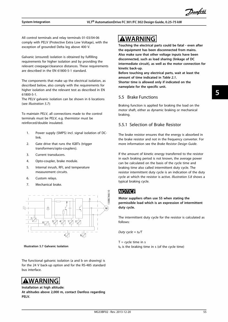
All control terminals and relay terminals 01-03/04-06comply with PELV (Protective Extra Low Voltage), with theexception of grounded Delta leg above 400 V.
Galvanic (ensured) isolation is obtained by fulfillingrequirements for higher isolation and by providing therelevant creepage/clearance distances. These requirementsare described in the EN 61800-5-1 standard.
The components that make up the electrical isolation, asdescribed below, also comply with the requirements forhigher isolation and the relevant test as described in EN61800-5-1.The PELV galvanic isolation can be shown in 6 locations(see Illustration 5.7):
To maintain PELV, all connections made to the controlterminals must be PELV, e.g. thermistor must bereinforced/double insulated.
1. Power supply (SMPS) incl. signal isolation of DC-link.
2. Gate drive that runs the IGBTs (triggertransformers/opto-couplers).
3. Current transducers.
4. Opto-coupler, brake module.
5. Internal inrush, RFI, and temperaturemeasurement circuits.
6. Custom relays.
7. Mechanical brake.
130B
C968
.10
1
3
25 46
ba
M
7
Illustration 5.7 Galvanic Isolation
The functional galvanic isolation (a and b on drawing) isfor the 24 V back-up option and for the RS-485 standardbus interface.
WARNINGInstallation at high altitude:At altitudes above 2,000 m, contact Danfoss regardingPELV.
WARNINGTouching the electrical parts could be fatal - even afterthe equipment has been disconnected from mains.Also make sure that other voltage inputs have beendisconnected, such as load sharing (linkage of DCintermediate circuit), as well as the motor connection forkinetic back-up.Before touching any electrical parts, wait at least theamount of time indicated in Table 2.1.Shorter time is allowed only if indicated on thenameplate for the specific unit.
5.5 Brake Functions
Braking function is applied for braking the load on themotor shaft, either as dynamic braking or mechanicalbraking.
5.5.1 Selection of Brake Resistor
The brake resistor ensures that the energy is absorbed inthe brake resistor and not in the frequency converter. Formore information see the Brake Resistor Design Guide.
If the amount of kinetic energy transferred to the resistorin each braking period is not known, the average powercan be calculated on the basis of the cycle time andbraking time also called intermittent duty cycle. Theresistor intermittent duty cycle is an indication of the dutycycle at which the resistor is active. Illustration 5.8 shows atypical braking cycle.
NOTICEMotor suppliers often use S5 when stating thepermissible load which is an expression of intermittentduty cycle.
The intermittent duty cycle for the resistor is calculated asfollows:
Duty cycle = tb/T
T = cycle time in stb is the braking time in s (of the cycle time)
System Integration VLT® AutomationDrive FC 301/FC 302 Design Guide, 0.25-75 kW
MG33BF02 - Rev. 2013-12-20 55
5 5
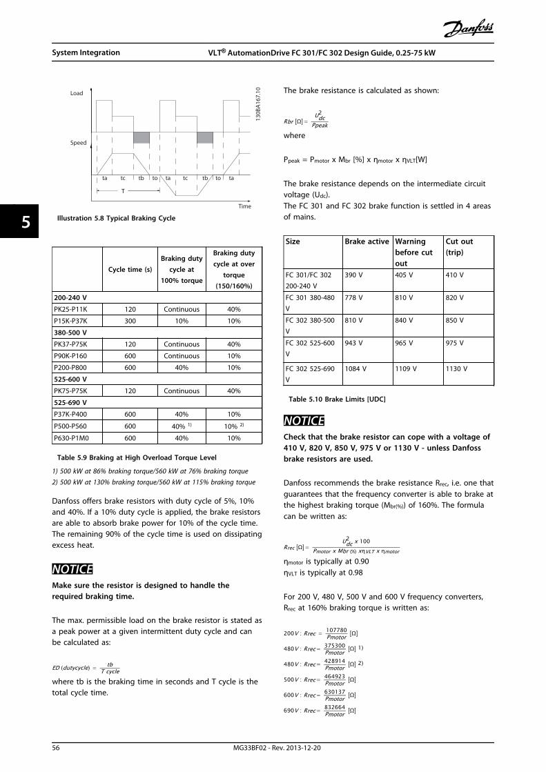
T
ta tc tb to ta tc tb to ta
130B
A16
7.10Load
Time
Speed
Illustration 5.8 Typical Braking Cycle
Cycle time (s)Braking duty
cycle at100% torque
Braking dutycycle at over
torque(150/160%)
200-240 V
PK25-P11K 120 Continuous 40%
P15K-P37K 300 10% 10%
380-500 V
PK37-P75K 120 Continuous 40%
P90K-P160 600 Continuous 10%
P200-P800 600 40% 10%
525-600 V
PK75-P75K 120 Continuous 40%
525-690 V
P37K-P400 600 40% 10%
P500-P560 600 40% 1) 10% 2)
P630-P1M0 600 40% 10%
Table 5.9 Braking at High Overload Torque Level
1) 500 kW at 86% braking torque/560 kW at 76% braking torque2) 500 kW at 130% braking torque/560 kW at 115% braking torque
Danfoss offers brake resistors with duty cycle of 5%, 10%and 40%. If a 10% duty cycle is applied, the brake resistorsare able to absorb brake power for 10% of the cycle time.The remaining 90% of the cycle time is used on dissipatingexcess heat.
NOTICEMake sure the resistor is designed to handle therequired braking time.
The max. permissible load on the brake resistor is stated asa peak power at a given intermittent duty cycle and canbe calculated as:
ED dutycycle = tbT cycle
where tb is the braking time in seconds and T cycle is thetotal cycle time.
The brake resistance is calculated as shown:
Rbr Ω = Udc
2
Ppeakwhere
Ppeak = Pmotor x Mbr [%] x ηmotor x ηVLT[W]
The brake resistance depends on the intermediate circuitvoltage (Udc).The FC 301 and FC 302 brake function is settled in 4 areasof mains.
Size Brake active Warningbefore cutout
Cut out(trip)
FC 301/FC 302200-240 V
390 V 405 V 410 V
FC 301 380-480V
778 V 810 V 820 V
FC 302 380-500V
810 V 840 V 850 V
FC 302 525-600V
943 V 965 V 975 V
FC 302 525-690V
1084 V 1109 V 1130 V
Table 5.10 Brake Limits [UDC]
NOTICECheck that the brake resistor can cope with a voltage of410 V, 820 V, 850 V, 975 V or 1130 V - unless Danfossbrake resistors are used.
Danfoss recommends the brake resistance Rrec, i.e. one thatguarantees that the frequency converter is able to brake atthe highest braking torque (Mbr(%)) of 160%. The formulacan be written as:
Rrec Ω = Udc
2 x 100Pmotor x Mbr % xηVLT x ηmotor
ηmotor is typically at 0.90ηVLT is typically at 0.98
For 200 V, 480 V, 500 V and 600 V frequency converters,Rrec at 160% braking torque is written as:
200V : Rrec = 107780Pmotor Ω
480V : Rrec = 375300Pmotor Ω 1
480V : Rrec = 428914Pmotor Ω 2
500V : Rrec = 464923Pmotor Ω
600V : Rrec = 630137Pmotor Ω
690V : Rrec = 832664Pmotor Ω
System Integration VLT® AutomationDrive FC 301/FC 302 Design Guide, 0.25-75 kW
56 MG33BF02 - Rev. 2013-12-20
55

1) For frequency converters ≤ 7.5 kW shaft output2) For frequency converters 11-75 kW shaft output
NOTICEThe resistor brake circuit resistance selected should notbe higher than that recommended by Danfoss. If a brakeresistor with a higher ohmic value is selected, the 160%braking torque may not be achieved because there is arisk that the frequency converter cuts out for safetyreasons.
NOTICEIf a short circuit in the brake transistor occurs, powerdissipation in the brake resistor is only prevented byusing a mains switch or contactor to disconnect themains for the frequency converter. (The contactor can becontrolled by the frequency converter).
CAUTION
The brake resistor gets hot during and after braking.
• To avoid personal injury, do not touch thebrake resistor
• Place the brake resistor in a secure environmentto avoid fire risk.
CAUTIONEnclosure types D-F frequency converters contain morethan one brake chopper. Consequently, use one brakeresistor per brake chopper for those enclosure types.
5.5.2 Brake Resistor Cabling
EMC (twisted cables/shielding)To meet the specified EMC performance of the frequencyconverter, use screened cables/wires. If unscreened wiresare used, it is recommended to twist the wires to reducethe electrical noise from the wires between the brakeresistor and the frequency converter.
For enhanced EMC performance, use a metal screen.
5.5.3 Control with Brake Function
The brake is protected against short-circuiting of the brakeresistor, and the brake transistor is monitored to ensurethat short-circuiting of the transistor is detected. A relay/digital output can be used for protecting the brake resistoragainst overloading in connection with a fault in thefrequency converter.In addition, the brake enables reading out the momentarypower and the mean power for the latest 120 s. The brakecan also monitor the power energising and ensure that it
does not exceed the limit selected in 2-12 Brake PowerLimit (kW). In 2-13 Brake Power Monitoring, select thefunction to carry out when the power transmitted to thebrake resistor exceeds the limit set in 2-12 Brake PowerLimit (kW).
NOTICEMonitoring the brake power is not a safety function; athermal switch is required for that purpose. The brakeresistor circuit is not earth leakage protected.
Overvoltage control (OVC) (exclusive brake resistor) can beselected as an alternative brake function in 2-17 Over-voltage Control. This function is active for all units. Thefunction ensures that a trip can be avoided, if the DC-linkvoltage increases. This is done by increasing the outputfrequency to limit the voltage from the DC-link. It is auseful function, e.g. if the ramp-down time is too shortsince tripping of the frequency converter is avoided. In thissituation, the ramp-down time is extended.
NOTICEOVC cannot be activated when running a PM motor(when 1-10 Motor Construction is set to [1] PM non salientSPM).
System Integration VLT® AutomationDrive FC 301/FC 302 Design Guide, 0.25-75 kW
MG33BF02 - Rev. 2013-12-20 57
5 5
6 Product Specifications
6.1 Electrical Data
6.1.1 Mains Supply 200-240 V
Type Designation PK25 PK37 PK55 PK75 P1K1 P1K5 P2K2 P3K0 P3K7
Typical Shaft Output [kW] 0.25 0.37 0.55 0,75 1.1 1.5 2.2 3.0 3.7
Enclosure IP20 (FC 301 only) A1 A1 A1 A1 A1 A1 - - -
Enclosure IP20/IP21 A2 A2 A2 A2 A2 A2 A2 A3 A3
Enclosure IP55, IP66 A4/A5 A4/A5 A4/A5 A4/A5 A4/A5 A4/A5 A4/A5 A5 A5
Output current
Continuous (200-240 V) [A] 1.8 2.4 3.5 4.6 6.6 7.5 10.6 12.5 16.7
Intermittent (200-240 V) [A] 2.9 3.8 5.6 7.4 10.6 12.0 17.0 20.0 26.7
Continuous kVA (208 V) [kVA] 0.65 0.86 1.26 1.66 2.38 2.70 3.82 4.50 6.00
Max. input current
Continuous (200-240 V) [A] 1.6 2.2 3.2 4.1 5.9 6.8 9.5 11.3 15.0
Intermittent (200-240 V) [A] 2.6 3.5 5.1 6.6 9.4 10.9 15.2 18.1 24.0
Additional Specifications
Max. cable cross section 4) for mains, motor,
brake and load sharing [mm2] ([AWG])
4,4,4 (12,12,12)(min. 0.2 (24))
Max. cable cross section 4) for disconnect
[mm2] ([AWG])6,4,4 (10,12,12)
Estimated power loss at rated max. load [W] 3) 21 29 42 54 63 82 116 155 185
Efficiency 2) 0.94 0.94 0.95 0.95 0.96 0.96 0.96 0.96 0.96
Table 6.1 Mains Supply 200-240 V, PK25-P3K7
Product Specifications VLT® AutomationDrive FC 301/FC 302 Design Guide, 0.25-75 kW
58 MG33BF02 - Rev. 2013-12-20
66
Type Designation P5K5 P7K5 P11K
High/Normal Overload1) HO NO HO NO HO NO
Typical Shaft Output [kW] 5.5 7.5 7.5 11 11 15
Enclosure IP20 B3 B3 B4
Enclosure IP21, IP55, IP66 B1 B1 B2
Output current
Continuous (200-240 V) [A] 24.2 30.8 30.8 46.2 46.2 59.4
Intermittent (60 s overload) (200-240 V) [A] 38.7 33.9 49.3 50.8 73.9 65.3
Continuous kVA (208 V) [kVA] 8.7 11.1 11.1 16.6 16.6 21.4
Max. input current
Continuous (200-240 V) [A] 22.0 28.0 28.0 42.0 42.0 54.0
Intermittent (60 s overload) (200-240 V) [A] 35.2 30.8 44.8 46.2 67.2 59.4
Additional Specifications
IP20 max. cable cross-section 4) for mains, brake, motor and load
sharing [mm2] ([AWG])10,10,- (8,8,-) 10,10,- (8,8,-) 35,-,- (2,-,-)
IP21 max. cable cross-section 4) for mains, brake and load sharing
[mm2] ([AWG])16,10,16 (6,8,6) 16,10,16 (6,8,6) 35,-,- (2,-,-)
IP21 max. cable cross-section 4) for motor [mm2] ([AWG]) 10,10,- (8,8,-) 10,10,- (8,8,-) 35,25,25 (2,4,4)
Max. cable cross-section 4) for Disconnect [mm2] ([AWG]) 16,10,10 (6,8,8)
Estimated power loss at rated max. load [W] 3) 239 310 371 514 463 602
Efficiency 2) 0.96 0.96 0.96
Table 6.2 Mains Supply 200-240 V, P5K5-P11K
Type Designation P15K P18K P22K P30K P37K
High/Normal Overload1) HO NO HO NO HO NO HO NO HO NO
Typical Shaft Output [kW] 15 18.5 18.5 22 22 30 30 37 37 45
Enclosure IP20 B4 C3 C3 C4 C4
Enclosure IP21, IP55, IP66 C1 C1 C1 C2 C2
Output current
Continuous (200-240 V) [A] 59.4 74.8 74.8 88.0 88.0 115 115 143 143 170
Intermittent (60 s overload) (200-240 V) [A] 89.1 82.3 112 96.8 132 127 173 157 215 187
Continuous kVA (208 V [kVA] 21.4 26.9 26.9 31.7 31.7 41.4 41.4 51.5 51.5 61.2
Max. input current
Continuous (200-240 V) [A] 54.0 68.0 68.0 80.0 80.0 104 104 130 130 154
Intermittent (60 s overload) (200-240 V) [A] 81.0 74.8 102 88.0 120 114 156 143 195 169
Additional Specifications
IP20 max. cable cross-section for mains, brake,
motor and load sharing [mm2] ([AWG])35 (2) 50 (1) 50 (1) 150 (300MCM) 150 (300MCM)
IP21, IP55, IP66 max. cable cross-section for
mains and motor [mm2] ([AWG])50 (1) 50 (1) 50 (1) 150 (300MCM) 150 (300MCM)
IP21, IP55, IP66 max. cable cross-section for
brake and load sharing [mm2] ([AWG])50 (1) 50 (1) 50 (1) 95 (3/0) 95 (3/0)
Max. cable cross-section 4) for Disconnect [mm2]([AWG])
50, 35, 35 (1, 2, 2)95, 70, 70
(3/0, 2/0, 2/0)
185, 150, 120(350MCM,300MCM, 4/0)
Estimated power loss at rated max. load [W] 3) 624 737 740 845 874 1140 1143 1353 1400 1636
Efficiency 2) 0.96 0.97 0.97 0.97 0.97
Table 6.3 Mains Supply 200-240 V, P15K-P37K
Product Specifications VLT® AutomationDrive FC 301/FC 302 Design Guide, 0.25-75 kW
MG33BF02 - Rev. 2013-12-20 59
6 6
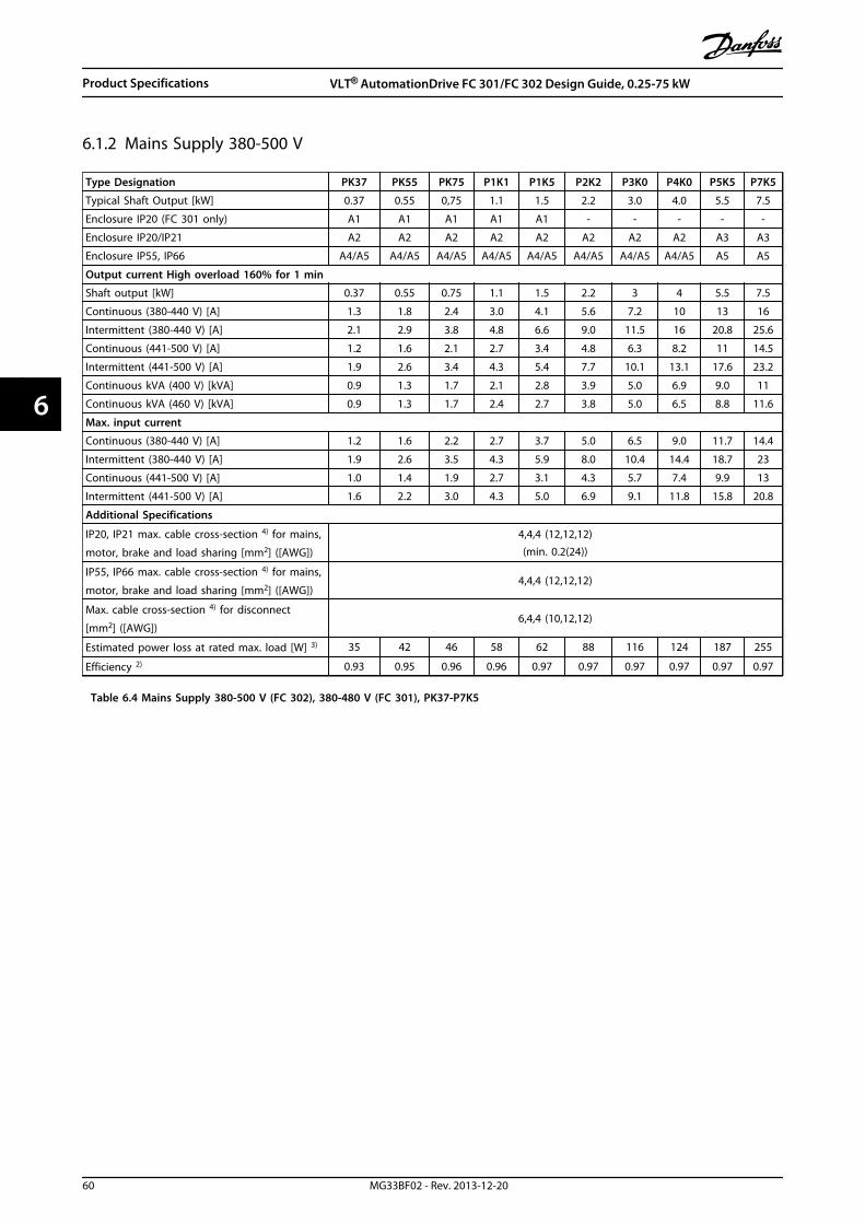
6.1.2 Mains Supply 380-500 V
Type Designation PK37 PK55 PK75 P1K1 P1K5 P2K2 P3K0 P4K0 P5K5 P7K5
Typical Shaft Output [kW] 0.37 0.55 0,75 1.1 1.5 2.2 3.0 4.0 5.5 7.5
Enclosure IP20 (FC 301 only) A1 A1 A1 A1 A1 - - - - -
Enclosure IP20/IP21 A2 A2 A2 A2 A2 A2 A2 A2 A3 A3
Enclosure IP55, IP66 A4/A5 A4/A5 A4/A5 A4/A5 A4/A5 A4/A5 A4/A5 A4/A5 A5 A5
Output current High overload 160% for 1 min
Shaft output [kW] 0.37 0.55 0.75 1.1 1.5 2.2 3 4 5.5 7.5
Continuous (380-440 V) [A] 1.3 1.8 2.4 3.0 4.1 5.6 7.2 10 13 16
Intermittent (380-440 V) [A] 2.1 2.9 3.8 4.8 6.6 9.0 11.5 16 20.8 25.6
Continuous (441-500 V) [A] 1.2 1.6 2.1 2.7 3.4 4.8 6.3 8.2 11 14.5
Intermittent (441-500 V) [A] 1.9 2.6 3.4 4.3 5.4 7.7 10.1 13.1 17.6 23.2
Continuous kVA (400 V) [kVA] 0.9 1.3 1.7 2.1 2.8 3.9 5.0 6.9 9.0 11
Continuous kVA (460 V) [kVA] 0.9 1.3 1.7 2.4 2.7 3.8 5.0 6.5 8.8 11.6
Max. input current
Continuous (380-440 V) [A] 1.2 1.6 2.2 2.7 3.7 5.0 6.5 9.0 11.7 14.4
Intermittent (380-440 V) [A] 1.9 2.6 3.5 4.3 5.9 8.0 10.4 14.4 18.7 23
Continuous (441-500 V) [A] 1.0 1.4 1.9 2.7 3.1 4.3 5.7 7.4 9.9 13
Intermittent (441-500 V) [A] 1.6 2.2 3.0 4.3 5.0 6.9 9.1 11.8 15.8 20.8
Additional Specifications
IP20, IP21 max. cable cross-section 4) for mains,
motor, brake and load sharing [mm2] ([AWG])
4,4,4 (12,12,12)(min. 0.2(24))
IP55, IP66 max. cable cross-section 4) for mains,
motor, brake and load sharing [mm2] ([AWG])4,4,4 (12,12,12)
Max. cable cross-section 4) for disconnect
[mm2] ([AWG])6,4,4 (10,12,12)
Estimated power loss at rated max. load [W] 3) 35 42 46 58 62 88 116 124 187 255
Efficiency 2) 0.93 0.95 0.96 0.96 0.97 0.97 0.97 0.97 0.97 0.97
Table 6.4 Mains Supply 380-500 V (FC 302), 380-480 V (FC 301), PK37-P7K5
Product Specifications VLT® AutomationDrive FC 301/FC 302 Design Guide, 0.25-75 kW
60 MG33BF02 - Rev. 2013-12-20
66

Type Designation P11K P15K P18K P22K
High/Normal Overload1) HO NO HO NO HO NO HO NO
Typical Shaft output [kW] 11 15 15 18.5 18.5 22.0 22.0 30.0
Enclosure IP20 B3 B3 B4 B4
Enclosure IP21 B1 B1 B2 B2
Enclosure IP55, IP66 B1 B1 B2 B2
Output current
Continuous (380-440 V) [A] 24 32 32 37.5 37.5 44 44 61
Intermittent (60 s overload) (380-440 V) [A] 38.4 35.2 51.2 41.3 60 48.4 70.4 67.1
Continuous (441-500 V) [A] 21 27 27 34 34 40 40 52
Intermittent (60 s overload)(441-500 V) [A]
33.6 29.7 43.2 37.4 54.4 44 64 57.2
Continuous kVA (400 V) [kVA] 16.6 22.2 22.2 26 26 30.5 30.5 42.3
Continuous kVA (460 V) [kVA] 21.5 27.1 31.9 41.4
Max. input current
Continuous (380-440 V) [A] 22 29 29 34 34 40 40 55
Intermittent (60 s overload)(380-440 V) [A]
35.2 31.9 46.4 37.4 54.4 44 64 60.5
Continuous (441-500 V) [A] 19 25 25 31 31 36 36 47
Intermittent (60 s overload)(441-500 V) [A]
30.4 27.5 40 34.1 49.6 39.6 57.6 51.7
Additional specifications
IP21, IP55, IP66 max. cable cross-section 4) for
mains, brake and load sharing [mm2] ([AWG])16, 10, 16 (6, 8, 6) 16, 10, 16 (6, 8, 6) 35,-,-(2,-,-) 35,-,-(2,-,-)
IP21, IP55, IP66 max. cable cross-section 4) for
motor [mm2] ([AWG])10, 10,- (8, 8,-) 10, 10,- (8, 8,-) 35, 25, 25 (2, 4, 4) 35, 25, 25 (2, 4, 4)
IP20 max. cable cross-section 4) for mains,
brake, motor and load sharing [mm2] ([AWG])10, 10,- (8, 8,-) 10, 10,- (8, 8,-) 35,-,-(2,-,-) 35,-,-(2,-,-)
Max. cable cross-section 4) for Disconnect
[mm2] ([AWG])16, 10, 10 (6, 8, 8)
Estimated power loss at rated max. load [W] 3) 291 392 379 465 444 525 547 739
Efficiency 2) 0.98 0.98 0.98 0.98
Table 6.5 Mains Supply 380-500 V (FC 302), 380-480 V (FC 301), P11K-P22K
Product Specifications VLT® AutomationDrive FC 301/FC 302 Design Guide, 0.25-75 kW
MG33BF02 - Rev. 2013-12-20 61
6 6
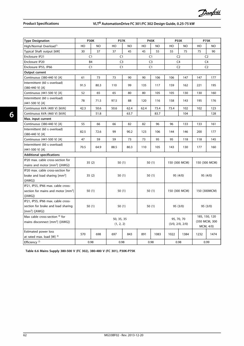
Type Designation P30K P37K P45K P55K P75K
High/Normal Overload1) HO NO HO NO HO NO HO NO HO NO
Typical Shaft output [kW] 30 37 37 45 45 55 55 75 75 90
Enclosure IP21 C1 C1 C1 C2 C2
Enclosure IP20 B4 C3 C3 C4 C4
Enclosure IP55, IP66 C1 C1 C1 C2 C2
Output current
Continuous (380-440 V) [A] 61 73 73 90 90 106 106 147 147 177
Intermittent (60 s overload)(380-440 V) [A]
91.5 80.3 110 99 135 117 159 162 221 195
Continuous (441-500 V) [A] 52 65 65 80 80 105 105 130 130 160
Intermittent (60 s overload)(441-500 V) [A]
78 71.5 97.5 88 120 116 158 143 195 176
Continuous kVA (400 V) [kVA] 42.3 50.6 50.6 62.4 62.4 73.4 73.4 102 102 123
Continuous kVA (460 V) [kVA] 51.8 63.7 83.7 104 128
Max. input current
Continuous (380-440 V) [A] 55 66 66 82 82 96 96 133 133 161
Intermittent (60 s overload)(380-440 V) [A]
82.5 72.6 99 90.2 123 106 144 146 200 177
Continuous (441-500 V) [A] 47 59 59 73 73 95 95 118 118 145
Intermittent (60 s overload)(441-500 V) [A]
70.5 64.9 88.5 80.3 110 105 143 130 177 160
Additional specifications
IP20 max. cable cross-section for
mains and motor [mm2] ([AWG])35 (2) 50 (1) 50 (1) 150 (300 MCM) 150 (300 MCM)
IP20 max. cable cross-section for
brake and load sharing [mm2]([AWG])
35 (2) 50 (1) 50 (1) 95 (4/0) 95 (4/0)
IP21, IP55, IP66 max. cable cross-
section for mains and motor [mm2]([AWG])
50 (1) 50 (1) 50 (1) 150 (300 MCM) 150 (300MCM)
IP21, IP55, IP66 max. cable cross-section for brake and load sharing
[mm2] ([AWG])
50 (1) 50 (1) 50 (1) 95 (3/0) 95 (3/0)
Max cable cross-section 4) for
mains disconnect [mm2] ([AWG])50, 35, 35
(1, 2, 2)95, 70, 70
(3/0, 2/0, 2/0)
185, 150, 120(350 MCM, 300
MCM, 4/0)
Estimated power loss
at rated max. load [W] 3)570 698 697 843 891 1083 1022 1384 1232 1474
Efficiency 2) 0.98 0.98 0.98 0.98 0.99
Table 6.6 Mains Supply 380-500 V (FC 302), 380-480 V (FC 301), P30K-P75K
Product Specifications VLT® AutomationDrive FC 301/FC 302 Design Guide, 0.25-75 kW
62 MG33BF02 - Rev. 2013-12-20
66

6.1.3 Mains Supply 525-600 V (FC 302 only)
Type Designation PK75 P1K1 P1K5 P2K2 P3K0 P4K0 P5K5 P7K5
Typical Shaft Output [kW] 0.75 1.1 1.5 2.2 3 4 5.5 7.5
Enclosure IP20, IP21 A3 A3 A3 A3 A3 A3 A3 A3
Enclosure IP55 A5 A5 A5 A5 A5 A5 A5 A5
Output current
Continuous (525-550 V) [A] 1.8 2.6 2.9 4.1 5.2 6.4 9.5 11.5
Intermittent (525-550 V) [A] 2.9 4.2 4.6 6.6 8.3 10.2 15.2 18.4
Continuous (551-600 V) [A] 1.7 2.4 2.7 3.9 4.9 6.1 9.0 11.0
Intermittent (551-600 V) [A] 2.7 3.8 4.3 6.2 7.8 9.8 14.4 17.6
Continuous kVA (525 V) [kVA] 1.7 2.5 2.8 3.9 5.0 6.1 9.0 11.0
Continuous kVA (575 V) [kVA] 1.7 2.4 2.7 3.9 4.9 6.1 9.0 11.0
Max. input current
Continuous (525-600 V) [A] 1.7 2.4 2.7 4.1 5.2 5.8 8.6 10.4
Intermittent (525-600 V) [A] 2.7 3.8 4.3 6.6 8.3 9.3 13.8 16.6
Additional specifications
Max. cable cross-section 4) for mains, motor,
brake and load sharing [mm2] ([AWG])
4,4,4 (12,12,12)(min. 0.2 (24))
Max. cable cross-section 4) for disconnect [mm2]([AWG])
6,4,4 (10,12,12)
Estimated power loss at rated max. load [W] 3) 35 50 65 92 122 145 195 261
Efficiency 2) 0.97 0.97 0.97 0.97 0.97 0.97 0.97 0.97
Table 6.7 Mains Supply 525-600 V (FC 302 only), PK75-P7K5
Product Specifications VLT® AutomationDrive FC 301/FC 302 Design Guide, 0.25-75 kW
MG33BF02 - Rev. 2013-12-20 63
6 6

Type Designation P11K P15K P18K P22K P30K
High/Normal Overload1) HO NO HO NO HO NO HO NO HO NO
Typical Shaft Output [kW] 11 15 15 18.5 18.5 22 22 30 30 37
Enclosure IP20 B3 B3 B4 B4 B4
Enclosure IP21, IP55, IP66 B1 B1 B2 B2 C1
Output current
Continuous (525-550 V) [A] 19 23 23 28 28 36 36 43 43 54
Intermittent (525-550 V) [A] 30 25 37 31 45 40 58 47 65 59
Continuous (551-600 V) [A] 18 22 22 27 27 34 34 41 41 52
Intermittent (551-600 V) [A] 29 24 35 30 43 37 54 45 62 57
Continuous kVA (550 V) [kVA] 18.1 21.9 21.9 26.7 26.7 34.3 34.3 41.0 41.0 51.4
Continuous kVA (575 V) [kVA] 17.9 21.9 21.9 26.9 26.9 33.9 33.9 40.8 40.8 51.8
Max. input current
Continuous at 550 V [A] 17.2 20.9 20.9 25.4 25.4 32.7 32.7 39 39 49
Intermittent at 550 V [A] 28 23 33 28 41 36 52 43 59 54
Continuous at 575 V [A] 16 20 20 24 24 31 31 37 37 47
Intermittent at 575 V [A] 26 22 32 27 39 34 50 41 56 52
Additional specifications
IP20 max. cable cross-section 4) formains, brake, motor and load
sharing [mm2] ([AWG])
10, 10,- (8, 8,-) 10, 10,- (8, 8,-) 35,-,-(2,-,-) 35,-,-(2,-,-) 35,-,-(2,-,-)
IP21, IP55, IP66 max. cable cross-
section 4) for mains, brake and load
sharing [mm2] ([AWG])
16, 10, 10 (6, 8, 8) 16, 10, 10 (6, 8, 8) 35,-,-(2,-,-) 35,-,-(2,-,-) 50,-,- (1,-,-)
IP21, IP55, IP66 max. cable cross-
section 4) for motor [mm2] ([AWG])10, 10,- (8, 8,-) 10, 10,- (8, 8,-) 35, 25, 25 (2, 4, 4) 35, 25, 25 (2, 4, 4) 50,-,- (1,-,-)
Max. cable cross-section 4) for
Disconnect [mm2] ([AWG])
16, 10, 10(6, 8, 8)
50, 35, 35(1, 2, 2)
Estimated power loss
at rated max. load [W] 3)220 300 300 370 370 440 440 600 600 740
Efficiency 2) 0.98 0.98 0.98 0.98 0.98
Table 6.8 Mains Supply 525-600 V (FC 302 only), P11K-P30K
Product Specifications VLT® AutomationDrive FC 301/FC 302 Design Guide, 0.25-75 kW
64 MG33BF02 - Rev. 2013-12-20
66

Type Designation P37K P45K P55K P75K
High/Normal Overload1) HO NO HO NO HO NO HO NO
Typical Shaft Output [kW] 37 45 45 55 55 75 75 90
Enclosure IP20 C3 C3 C3 C4 C4
Enclosure IP21, IP55, IP66 C1 C1 C1 C2 C2
Output current
Continuous (525-550 V) [A] 54 65 65 87 87 105 105 137
Intermittent (525-550 V) [A] 81 72 98 96 131 116 158 151
Continuous (551-600 V) [A] 52 62 62 83 83 100 100 131
Intermittent (551-600 V) [A] 78 68 93 91 125 110 150 144
Continuous kVA (550 V) [kVA] 51.4 61.9 61.9 82.9 82.9 100.0 100.0 130.5
Continuous kVA (575 V) [kVA] 51.8 61.7 61.7 82.7 82.7 99.6 99.6 130.5
Max. input current
Continuous at 550 V [A] 49 59 59 78.9 78.9 95.3 95.3 124.3
Intermittent at 550 V [A] 74 65 89 87 118 105 143 137
Continuous at 575 V [A] 47 56 56 75 75 91 91 119
Intermittent at 575 V [A] 70 62 85 83 113 100 137 131
Additional specifications
IP20 max. cable cross-section for mains and motor
[mm2] ([AWG])50 (1) 150 (300 MCM)
IP20 max. cable cross-section for brake and load
sharing [mm2] ([AWG])50 (1) 95 (4/0)
IP21, IP55, IP66 max. cable cross-section for mains and
motor [mm2] ([AWG])50 (1) 150 (300 MCM)
IP21, IP55, IP66 max. cable cross-section for brake and
load sharing [mm2] ([AWG])50 (1) 95 (4/0)
Max cable cross-section 4) for mains disconnect [mm2]([AWG])
50, 35, 35(1, 2, 2)
95, 70, 70(3/0, 2/0, 2/0)
185, 150, 120(350MCM,
300MCM, 4/0)
Estimated power loss at rated max. load [W] 3) 740 900 900 1100 1100 1500 1500 1800
Efficiency 2) 0.98 0.98 0.98 0.98
Table 6.9 Mains Supply 525-600 V (FC 302 only), P37K-P75K
Product Specifications VLT® AutomationDrive FC 301/FC 302 Design Guide, 0.25-75 kW
MG33BF02 - Rev. 2013-12-20 65
6 6

6.1.4 Mains Supply 525-690 V (FC 302 only)
Type Designation P1K1 P1K5 P2K2 P3K0 P4K0 P5K5 P7K5
High/Normal Overload1) HO/NO HO/NO HO/NO HO/NO HO/NO HO/NO HO/NO
Typical Shaft output (kW) 1.1 1.5 2.2 3.0 4.0 5.5 7.5
Enclosure IP20 A3 A3 A3 A3 A3 A3 A3
Output current
Continuous (525-550V) [A] 2.1 2.7 3.9 4.9 6.1 9.0 11.0
Intermittent (525-550V) [A] 3.4 4.3 6.2 7.8 9.8 14.4 17.6
Continuous (551-690V) [A] 1.6 2.2 3.2 4.5 5.5 7.5 10.0
Intermittent (551-690V) [A] 2.6 3.5 5.1 7.2 8.8 12.0 16.0
Continuous KVA 525 V 1.9 2.5 3.5 4.5 5.5 8.2 10.0
Continuous KVA 690 V 1.9 2.6 3.8 5.4 6.6 9.0 12.0
Max. input current
Continuous (525-550V) [A] 1.9 2.4 3.5 4.4 5.5 8.1 9.9
Intermittent (525-550V) [A] 3.0 3.9 5.6 7.0 8.8 12.9 15.8
Continuous (551-690V) [A] 1.4 2.0 2.9 4.0 4.9 6.7 9.0
Intermittent (551-690V) [A] 2.3 3.2 4.6 6.5 7.9 10.8 14.4
Additional specifications
Max. cable cross-section 4) for mains, motor, brake and
load sharing [mm2] ([AWG])4, 4, 4 (12, 12, 12) (min. 0.2 (24)
Max. Cable cross-section 4) for disconnect [mm2]([AWG])
6, 4, 4 (10, 12, 12)
Estimated power loss at rated max. load (W) 3) 44 60 88 120 160 220 300
Efficiency 2) 0.96 0.96 0.96 0.96 0.96 0.96 0.96
Table 6.10 A3 Enclosure, Mains Supply 525-690 V IP20/Protected Chassis, P1K1-P7K5
Type Designation P11K P15K P18K P22K
High/Normal Overload1) HO NO HO NO HO NO HO NO
Typical Shaft output at 550 V [kW] 7.5 11 11 15 15 18.5 18.5 22
Typical Shaft output at 690 V [kW] 11 15 15 18.5 18.5 22 22 30
Enclosure IP20 B4 B4 B4 B4
Enclosure IP21, IP55 B2 B2 B2 B2
Output current
Continuous (525-550V) [A] 14.0 19.0 19.0 23.0 23.0 28.0 28.0 36.0
Intermittent (60 s overload) (525-550V) [A] 22.4 20.9 30.4 25.3 36.8 30.8 44.8 39.6
Continuous (551-690V) [A] 13.0 18.0 18.0 22.0 22.0 27.0 27.0 34.0
Intermittent (60 s overload) (551-690V) [A] 20.8 19.8 28.8 24.2 35.2 29.7 43.2 37.4
continuous KVA (at 550 V) [KVA] 13.3 18.1 18.1 21.9 21.9 26.7 26.7 34.3
continuous KVA (at 690 V) [KVA] 15.5 21.5 21.5 26.3 26.3 32.3 32.3 40.6
Max. input current
Continuous (at 550 V) (A) 15.0 19.5 19.5 24.0 24.0 29.0 29.0 36.0
Intermittent (60 s overload) (at 550 V) (A) 23.2 21.5 31.2 26.4 38.4 31.9 46.4 39.6
Continuous (at 690 V) (A) 14.5 19.5 19.5 24.0 24.0 29.0 29.0 36.0
Intermittent (60 s overload) (at 690 V) (A) 23.2 21.5 31.2 26.4 38.4 31.9 46.4 39.6
Additional specifications
Max. cable cross-section 4) for mains/motor, load
share and brake [mm2] ([AWG])35, 25, 25 (2, 4, 4)
Max cable cross-section 4) for mains disconnect
[mm2] ([AWG])16,10,10 (6, 8, 8)
Estimated power loss at rated max. load (W) 3) 150 220 220 300 300 370 370 440
Efficiency 2) 0.98 0.98 0.98 0.98
Table 6.11 B2/B4 Enclosure, Mains Supply 525-690 V IP20/IP21/IP55 - Chassis/NEMA 1/NEMA 12 (FC 302 only), P11K-P22K
Product Specifications VLT® AutomationDrive FC 301/FC 302 Design Guide, 0.25-75 kW
66 MG33BF02 - Rev. 2013-12-20
66

Type Designation P30K P37K P45K P55K P75K
High/Normal Overload1) HO NO HO NO HO NO HO NO HO NO
Typical Shaft output at 550 V (kW) 22 30 30 37 37 45 45 55 50 75
Typical Shaft output at 690 V [kW] 30 37 37 45 45 55 55 75 75 90
Enclosure IP20 B4 C3 C3 D3h D3h
Enclosure IP21, IP55 C2 C2 C2 C2 C2
Output current
Continuous (525-550V) [A] 36.0 43.0 43.0 54.0 54.0 65.0 65.0 87.0 87.0 105
Intermittent (60 s overload) (525-550V) [A] 54.0 47.3 64.5 59.4 81.0 71.5 97.5 95.7 130.5 115.5
Continuous (551-690V) [A] 34.0 41.0 41.0 52.0 52.0 62.0 62.0 83.0 83.0 100
Intermittent (60 s overload) (551-690V) [A] 51.0 45.1 61.5 57.2 78.0 68.2 93.0 91.3 124.5 110
continuous KVA (at 550 V) [KVA] 34.3 41.0 41.0 51.4 51.4 61.9 61.9 82.9 82.9 100
continuous KVA (at 690 V) [KVA] 40.6 49.0 49.0 62.1 62.1 74.1 74.1 99.2 99.2 119.5
Max. input current
Continuous (at 550 V) [A] 36.0 49.0 49.0 59.0 59.0 71.0 71.0 87.0 87.0 99.0
Intermittent (60 s overload) (at 550 V) [A] 54.0 53.9 72.0 64.9 87.0 78.1 105.0 95.7 129 108.9
Continuous (at 690 V) [A] 36.0 48.0 48.0 58.0 58.0 70.0 70.0 86.0 - -
Intermittent (60 s overload) (at 690 V) [A] 54.0 52.8 72.0 63.8 87.0 77.0 105 94.6 - -
Additional specifications
Max. cable-cross section for mains and
motor [mm2] ([AWG])150 (300 MCM)
Max. cable cross-section for load share and
brake [mm2] ([AWG])95 (3/0)
Max cable cross-section 4) for mains
disconnect [mm2] ([AWG])
95, 70, 70(3/0, 2/0, 2/0)
185, 150, 120(350 MCM, 300
MCM, 4/0)-
Estimated power loss
at rated max. load [W] 3)600 740 740 900 900 1100 1100 1500 1500 1800
Efficiency 2) 0,98 0,98 0,98 0,98 0,98
Table 6.12 B4, C2, C3 Enclosure, Mains Supply 525-690 V IP20/IP21/IP55 - Chassis/NEMA1/NEMA 12 (FC 302 only), P30K-P75K
For fuse ratings, see chapter 9.3.1 Fuses and Circuit Breakers.
1) High overload=150% or 160% torque during 60 s. Normal overload=110% torque during 60 s.
2) Measured using 5 m screened motor cables at rated load and rated frequency.
3) The typical power loss is at nominal load conditions and expected to be within ±15% (tolerance relates to variety in voltage andcable conditions).Values are based on a typical motor efficiency (eff2/eff3 border line). Motors with lower efficiency also add to the power loss in thefrequency converter and opposite.If the switching frequency is increased compared to the default setting, the power losses may rise significantly.LCP and typical control card power consumptions are included. Further options and customer load may add up to 30 W to the losses.(Though typical only 4 W extra for a fully loaded control card, or options for slot A or slot B, each).
Although measurements are made with state of the art equipment, some measurement inaccuracy must be allowed for (± 5%).
4) The 3 values for the max. cable cross section are for single core, flexible wire and flexible wire with sleeve, respectively.
Product Specifications VLT® AutomationDrive FC 301/FC 302 Design Guide, 0.25-75 kW
MG33BF02 - Rev. 2013-12-20 67
6 6
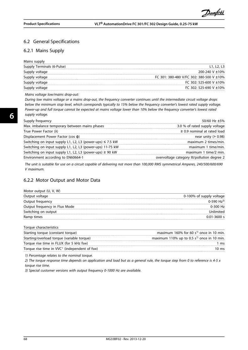
6.2 General Specifications
6.2.1 Mains Supply
Mains supplySupply Terminals (6-Pulse) L1, L2, L3Supply voltage 200-240 V ±10%Supply voltage FC 301: 380-480 V/FC 302: 380-500 V ±10%Supply voltage FC 302: 525-600 V ±10%Supply voltage FC 302: 525-690 V ±10%
Mains voltage low/mains drop-out:During low mains voltage or a mains drop-out, the frequency converter continues until the intermediate circuit voltage dropsbelow the minimum stop level, which corresponds typically to 15% below the frequency converter's lowest rated supply voltage.Power-up and full torque cannot be expected at mains voltage lower than 10% below the frequency converter's lowest ratedsupply voltage.
Supply frequency 50/60 Hz ±5%Max. imbalance temporary between mains phases 3.0 % of rated supply voltageTrue Power Factor (λ) ≥ 0.9 nominal at rated loadDisplacement Power Factor (cos ϕ) near unity (> 0.98)Switching on input supply L1, L2, L3 (power-ups) ≤ 7.5 kW maximum 2 times/min.Switching on input supply L1, L2, L3 (power-ups) 11-75 kW maximum 1 time/min.Switching on input supply L1, L2, L3 (power-ups) ≥ 90 kW maximum 1 time/2 min.Environment according to EN60664-1 overvoltage category III/pollution degree 2
The unit is suitable for use on a circuit capable of delivering not more than 100,000 RMS symmetrical Amperes, 240/500/600/690V maximum.
6.2.2 Motor Output and Motor Data
Motor output (U, V, W)Output voltage 0-100% of supply voltageOutput frequency 0-590 Hz3)
Output frequency in Flux Mode 0-300 HzSwitching on output UnlimitedRamp times 0.01-3600 s
Torque characteristicsStarting torque (constant torque) maximum 160% for 60 s1) once in 10 min.Starting/overload torque (variable torque) maximum 110% up to 0.5 s1) once in 10 min.Torque rise time in FLUX (for 5 kHz fsw) 1 msTorque rise time in VVC+ (independent of fsw) 10 ms
1) Percentage relates to the nominal torque.2) The torque response time depends on application and load but as a general rule, the torque step from 0 to reference is 4-5 xtorque rise time.3) Special customer versions with output frequency 0-1000 Hz are available.
Product Specifications VLT® AutomationDrive FC 301/FC 302 Design Guide, 0.25-75 kW
68 MG33BF02 - Rev. 2013-12-20
66

6.2.3 Ambient Conditions
EnvironmentEnclosure IP20/Chassis, IP21/Type 1, IP55/ Type 12, IP66/ Type 4XVibration test 1.0 gMax. THVD 10%Max. relative humidity 5% - 93% (IEC 721-3-3; Class 3K3 (non-condensing) during operationAggressive environment (IEC 60068-2-43) H2S test class KdAmbient temperature Max. 50 °C (24-hour average maximum 45 °C)Minimum ambient temperature during full-scale operation 0 °CMinimum ambient temperature at reduced performance - 10 °CTemperature during storage/transport -25 to +65/70 °CMaximum altitude above sea level without derating 1000 mEMC standards, Emission EN 61800-3, EN 550111)
EMC standards, Immunity EN61800-3, EN 61000-6-1/2
1) See chapter 5.2.1 EMC Test Results
6.2.4 Cable Specifications
Cable lengths and cross sections for control cables1)
Max. motor cable length, screened 150 mMax. motor cable length, unscreened 300 mMaximum cross section to control terminals, flexible/rigid wire without cable end sleeves 1.5 mm2/16 AWGMaximum cross section to control terminals, flexible wire with cable end sleeves 1 mm2/18 AWGMaximum cross section to control terminals, flexible wire with cable end sleeves with collar 0.5 mm2/20 AWGMinimum cross section to control terminals 0.25 mm2/24 AWG
1) For power cables, see electrical tables in chapter 6.1 Electrical Data.
6.2.5 Control Input/Output and Control Data
6.2.5.1 Digital Inputs
Digital inputsProgrammable digital inputs FC 301: 4 (5)1)/FC 302: 4 (6)1)
Terminal number 18, 19, 271), 291), 32, 33Logic PNP or NPNVoltage level 0 - 24 V DCVoltage level, logic'0' PNP < 5 V DCVoltage level, logic'1' PNP > 10 V DCVoltage level, logic '0' NPN2) > 19 V DCVoltage level, logic '1' NPN2) < 14 V DCMaximum voltage on input 28 V DCPulse frequency range 0-110 kHz(Duty cycle) Min. pulse width 4.5 msInput resistance, Ri approx. 4 kΩ
Product Specifications VLT® AutomationDrive FC 301/FC 302 Design Guide, 0.25-75 kW
MG33BF02 - Rev. 2013-12-20 69
6 6
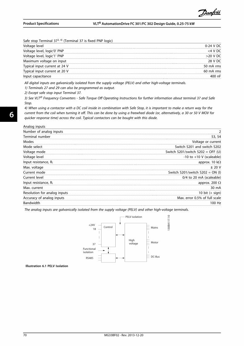
Safe stop Terminal 373, 4) (Terminal 37 is fixed PNP logic)Voltage level 0-24 V DCVoltage level, logic'0' PNP <4 V DCVoltage level, logic'1' PNP >20 V DCMaximum voltage on input 28 V DCTypical input current at 24 V 50 mA rmsTypical input current at 20 V 60 mA rmsInput capacitance 400 nF
All digital inputs are galvanically isolated from the supply voltage (PELV) and other high-voltage terminals.1) Terminals 27 and 29 can also be programmed as output.2) Except safe stop input Terminal 37.3) See VLT® Frequency Converters - Safe Torque Off Operating Instructions for further information about terminal 37 and SafeStop.4) When using a contactor with a DC coil inside in combination with Safe Stop, it is important to make a return way for thecurrent from the coil when turning it off. This can be done by using a freewheel diode (or, alternatively, a 30 or 50 V MOV forquicker response time) across the coil. Typical contactors can be bought with this diode.
Analog inputsNumber of analog inputs 2Terminal number 53, 54Modes Voltage or currentMode select Switch S201 and switch S202Voltage mode Switch S201/switch S202 = OFF (U)Voltage level -10 to +10 V (scaleable)Input resistance, Ri approx. 10 kΩMax. voltage ± 20 VCurrent mode Switch S201/switch S202 = ON (I)Current level 0/4 to 20 mA (scaleable)Input resistance, Ri approx. 200 ΩMax. current 30 mAResolution for analog inputs 10 bit (+ sign)Accuracy of analog inputs Max. error 0.5% of full scaleBandwidth 100 Hz
The analog inputs are galvanically isolated from the supply voltage (PELV) and other high-voltage terminals.
Mains
Functionalisolation
PELV isolation
Motor
DC-Bus
Highvoltage
Control+24V
RS485
18
37
130B
A11
7.10
Illustration 6.1 PELV Isolation
Product Specifications VLT® AutomationDrive FC 301/FC 302 Design Guide, 0.25-75 kW
70 MG33BF02 - Rev. 2013-12-20
66
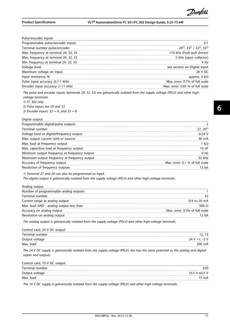
Pulse/encoder inputsProgrammable pulse/encoder inputs 2/1Terminal number pulse/encoder 291), 332) / 323), 333)
Max. frequency at terminal 29, 32, 33 110 kHz (Push-pull driven)Max. frequency at terminal 29, 32, 33 5 kHz (open collector)Min. frequency at terminal 29, 32, 33 4 HzVoltage level see section on Digital inputMaximum voltage on input 28 V DCInput resistance, Ri approx. 4 kΩPulse input accuracy (0.1-1 kHz) Max. error: 0.1% of full scaleEncoder input accuracy (1-11 kHz) Max. error: 0.05 % of full scale
The pulse and encoder inputs (terminals 29, 32, 33) are galvanically isolated from the supply voltage (PELV) and other high-voltage terminals.1) FC 302 only2) Pulse inputs are 29 and 333) Encoder inputs: 32 = A, and 33 = B
Digital outputProgrammable digital/pulse outputs 2Terminal number 27, 291)
Voltage level at digital/frequency output 0-24 VMax. output current (sink or source) 40 mAMax. load at frequency output 1 kΩMax. capacitive load at frequency output 10 nFMinimum output frequency at frequency output 0 HzMaximum output frequency at frequency output 32 kHzAccuracy of frequency output Max. error: 0.1 % of full scaleResolution of frequency outputs 12 bit
1) Terminal 27 and 29 can also be programmed as input.The digital output is galvanically isolated from the supply voltage (PELV) and other high-voltage terminals.
Analog outputNumber of programmable analog outputs 1Terminal number 42Current range at analog output 0/4 to 20 mAMax. load GND - analog output less than 500 ΩAccuracy on analog output Max. error: 0.5% of full scaleResolution on analog output 12 bit
The analog output is galvanically isolated from the supply voltage (PELV) and other high-voltage terminals.
Control card, 24 V DC outputTerminal number 12, 13Output voltage 24 V +1, -3 VMax. load 200 mA
The 24 V DC supply is galvanically isolated from the supply voltage (PELV), but has the same potential as the analog and digitalinputs and outputs.
Control card, 10 V DC outputTerminal number ±50Output voltage 10.5 V ±0.5 VMax. load 15 mA
The 10 V DC supply is galvanically isolated from the supply voltage (PELV) and other high-voltage terminals.
Product Specifications VLT® AutomationDrive FC 301/FC 302 Design Guide, 0.25-75 kW
MG33BF02 - Rev. 2013-12-20 71
6 6

Control card, RS-485 serial communicationTerminal number 68 (P,TX+, RX+), 69 (N,TX-, RX-)Terminal number 61 Common for terminals 68 and 69
The RS-485 serial communication circuit is functionally separated from other central circuits and galvanically isolated from thesupply voltage (PELV).
Control card, USB serial communication USB standard 1.1 (Full speed)USB plug USB type B “device” plug
Connection to PC is carried out via a standard host/device USB cable.The USB connection is galvanically isolated from the supply voltage (PELV) and other high-voltage terminals.The USB ground connection is not galvanically isolated from protection earth. Use only an isolated laptop as PC connection tothe USB connector on the frequency converter.
Relay outputsProgrammable relay outputs FC 301 all kW: 1/FC 302 all kW: 2Relay 01 Terminal number 1-3 (break), 1-2 (make)Max. terminal load (AC-1)1) on 1-3 (NC), 1-2 (NO) (Resistive load) 240 V AC, 2 AMax. terminal load (AC-15)1) (Inductive load @ cosφ 0.4) 240 V AC, 0.2 AMax. terminal load (DC-1)1) on 1-2 (NO), 1-3 (NC) (Resistive load) 60 V DC, 1 AMax. terminal load (DC-13)1) (Inductive load) 24 V DC, 0.1 ARelay 02 (FC 302 only) Terminal number 4-6 (break), 4-5 (make)Max. terminal load (AC-1)1) on 4-5 (NO) (Resistive load)2)3) Overvoltage cat. II 400 V AC, 2 AMax. terminal load (AC-15)1) on 4-5 (NO) (Inductive load @ cosφ 0.4) 240 V AC, 0.2 AMax. terminal load (DC-1)1) on 4-5 (NO) (Resistive load) 80 V DC, 2 AMax. terminal load (DC-13)1) on 4-5 (NO) (Inductive load) 24 V DC, 0.1 AMax. terminal load (AC-1)1) on 4-6 (NC) (Resistive load) 240 V AC, 2 AMax. terminal load (AC-15)1) on 4-6 (NC) (Inductive load @ cosφ 0.4) 240 V AC, 0.2 AMax. terminal load (DC-1)1) on 4-6 (NC) (Resistive load) 50 V DC, 2 AMax. terminal load (DC-13)1) on 4-6 (NC) (Inductive load) 24 V DC, 0.1 AMin. terminal load on 1-3 (NC), 1-2 (NO), 4-6 (NC), 4-5 (NO) 24 V DC 10 mA, 24 V AC 20 mAEnvironment according to EN 60664-1 overvoltage category III/pollution degree 2
1) IEC 60947 part 4 and 5The relay contacts are galvanically isolated from the rest of the circuit by reinforced isolation (PELV).2) Overvoltage Category II3) UL applications 300 V AC 2A
Control card performanceScan interval 1 ms
Control characteristicsResolution of output frequency at 0-590 Hz ±0.003 HzRepeat accuracy of Precise start/stop (terminals 18, 19) ≤±0.1 msSystem response time (terminals 18, 19, 27, 29, 32, 33) ≤ 2 msSpeed control range (open loop) 1:100 of synchronous speedSpeed control range (closed loop) 1:1000 of synchronous speedSpeed accuracy (open loop) 30-4000 rpm: error ±8 rpmSpeed accuracy (closed loop), depending on resolution of feedback device 0-6000 rpm: error ±0.15 rpmTorque control accuracy (speed feedback) max error ±5% of rated torque
All control characteristics are based on a 4-pole asynchronous motor
Product Specifications VLT® AutomationDrive FC 301/FC 302 Design Guide, 0.25-75 kW
72 MG33BF02 - Rev. 2013-12-20
66

6.2.6 Derating for Ambient Temperature
6.2.6.1 Derating for Ambient Temperature,Enclosure Type A
60° AVM - Pulse Width Modulation
2
20%
4 6 8 10 12 14 16
40%
60%
80%
100%110%
Iout (%)
fsw (kHz)
A1-A3 45°C, A4-A5 40°CA1-A3 50°C, A4-A5 45°CA1-A3 55°C, A4-A5 50°C
130B
A39
3.10
00
Illustration 6.2 Derating of Iout for Different TAMB, MAX for
Enclosure Type A, using 60° AVM
SFAVM - Stator Frequency Asyncron Vector Modulation
2
20%
4 6 8 10 12 14 16
40%
60%
80%
100%110%
A1-A3 45°C, A4-A5 40°CA1-A3 50°C, A4-A5 45°CA1-A3 55°C, A4-A5 50°C
00
130B
D63
9.10Iout (%)
fsw (kHz)
Illustration 6.3 Derating of Iout for Different TAMB, MAX for
Enclosures Type A, using SFAVM
When using only 10 m motor cable or less in enclosuretype A, less derating is necessary. This is due to the factthat the length of the motor cable has a relatively highimpact on the recommended derating.
60° AVM
2
20%
4 6 8 10 12 14 16
40%
60%
80%
100%110%
Iout (%)
A1-A3 45°C, A4-A5 40°CA1-A3 50°C, A4-A5 45°CA1-A3 55°C, A4-A5 50°C
00
130B
A39
4.10
fsw (kHz)
Illustration 6.4 Derating of Iout for Different TAMB, MAX for
Enclosures Type A, using 60° AVM and maximum 10 m motorcable
SFAVM
2
20%
4 6 8 10 12 14 16
40%
60%
80%
100%110%
Iout (%)
A1-A3 45°C, A4-A5 40°CA1-A3 50°C, A4-A5 45°CA1-A3 55°C, A4-A5 50°C
00
130B
D64
0.10
fsw (kHz)
Illustration 6.5 Derating of Iout for Different TAMB, MAX for
Enclosures Type A, using SFAVM and maximum 10 m motorcable
6.2.6.2 Derating for Ambient Temperature,Enclosure Types B
Enclosure B, T2, T4 and T5For the enclosure types B and C the derating also dependson the overload mode selected in 1-04 Overload Mode
60° AVM - Pulse Width Modulation
2
20%
4 6 8 10 12 14 16
40%
60%
80%
100%110%
fsw (kHz)
45°C
50°C
55°C
130B
A40
2.10
00
Iout (%)HO
B1B2
Illustration 6.6 Derating of Iout for different TAMB, MAX for
Enclosure Types B1 and B2, using 60° AVM in High overloadmode (160% over torque)
2
20%
4 6 8 10 12 14 16
40%
60%
80%
100%110%
fsw (kHz)
00
Iout (%)NO
45°C
50°C
55°C
130B
A40
1.11
B1B2
Illustration 6.7 Derating of Iout for different TAMB, MAX for
Enclosure Types B1 and B2, using 60° AVM in Normaloverload mode (110% over torque)
Product Specifications VLT® AutomationDrive FC 301/FC 302 Design Guide, 0.25-75 kW
MG33BF02 - Rev. 2013-12-20 73
6 6
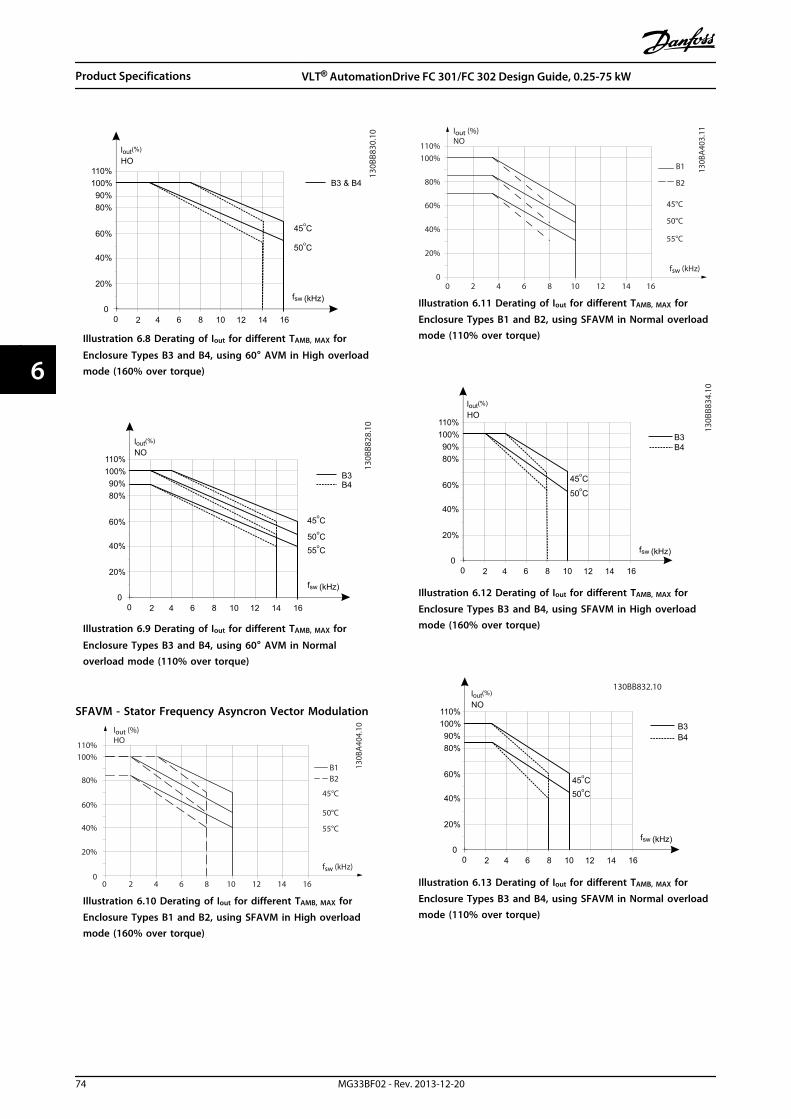
130B
B830
.10
2 4 6 8
20%
10 12 14 16
fsw (kHz)
00
40%
o50 C
60%
80%90%
100%
o45 C
110%
(%)lout
B3 & B4
HO
Illustration 6.8 Derating of Iout for different TAMB, MAX for
Enclosure Types B3 and B4, using 60° AVM in High overloadmode (160% over torque)
2 4 6 8
20%
10
40%
60%
80%90%
100%
o50 C
o45 C
110%
12 14 16
o55 C
fsw (kHz)
00
(%)lout
B3B4
NO
130B
B828
.10
Illustration 6.9 Derating of Iout for different TAMB, MAX for
Enclosure Types B3 and B4, using 60° AVM in Normaloverload mode (110% over torque)
SFAVM - Stator Frequency Asyncron Vector Modulation
2
20%
4 6 8 10 12 14 16
40%
60%
80%
100%110%
fsw (kHz)
45°C
50°C
55°C
130B
A40
4.10
00
Iout (%)HO
B1B2
Illustration 6.10 Derating of Iout for different TAMB, MAX for
Enclosure Types B1 and B2, using SFAVM in High overloadmode (160% over torque)
2
20%
4 6 8 10 12 14 16
40%
60%
80%
100%110%
fsw (kHz)
45°C
50°C
55°C
00
Iout (%)NO
130B
A40
3.11
B1
B2
Illustration 6.11 Derating of Iout for different TAMB, MAX for
Enclosure Types B1 and B2, using SFAVM in Normal overloadmode (110% over torque)
130B
B834
.10
2 4 6 8
20%
10 12 14 16
fsw (kHz)
00
40%
60%
80%90%
100%
o50 C
o45 C
110%
B3
(%)loutHO
B4
Illustration 6.12 Derating of Iout for different TAMB, MAX for
Enclosure Types B3 and B4, using SFAVM in High overloadmode (160% over torque)
2 4 6 8
20%
10
40%
60%
80%90%
100%
o50 C
o45 C
110%
12 14 16
B3B4
fsw (kHz)
00
(%)loutNO
130BB832.10
Illustration 6.13 Derating of Iout for different TAMB, MAX for
Enclosure Types B3 and B4, using SFAVM in Normal overloadmode (110% over torque)
Product Specifications VLT® AutomationDrive FC 301/FC 302 Design Guide, 0.25-75 kW
74 MG33BF02 - Rev. 2013-12-20
66

Enclosures B, T660° AVM - Pulse Width Modulation
1 2 4 6 8
20%
10
40%
60%
80%90%
100%
o50 C
o45 C
110%
3
(%)lout
fsw (kHz)
00
B1 & B2
NO 130B
B820
.10
Illustration 6.14 Output current derating with switchingfrequency and ambient temperature for 600 V frequencyconverters, enclosure types B, 60 AVM, NO
1 2 4 6 8
20%
10
40%
o50 C
fsw (kHz)
00
60%
80%90%
100%
o45 C
110%
(%)lout
B1 & B2
HO
130B
B822
.10
Illustration 6.15 Output current derating with switchingfrequency and ambient temperature for 600 V frequencyfonverters, enclosure type B, 60 AVM, HO
SFAVM - Stator Frequency Asyncron Vector Modulation
1 2 4 6 8
20%
10
40%
60%
80%90%
100%
o50 C
o45 C
110%
fsw (kHz)
00
(%)lout
B1 & B2
NO
130B
B826
.10
Illustration 6.16 Output current derating with switchingfrequency and ambient temperature for 600 V frequencyconverters, enclosure type B; SFAVM, NO
1 2 4 6 8
20%
10
40%
60%
80%90%
100%
o50 C
o45 C
110%
fsw (kHz)
00
(%)lout
B1 & B2
HO
130B
B824
.10
Illustration 6.17 Output current derating with switchingfrequency and ambient temperature for 600 V frequencyconverters, enclosure type B; SFAVM, HO
Enclosures B, T7Enclosures B2 and B4, 525-690 V60° AVM - Pulse Width Modulation
fsw (kHz)
130B
B211
.10
13.6
20.4
27.2
34
Iout (A)
30.6
1 2 64
55°C
50°C
45°C
8 10
B2 all options
Illustration 6.18 Output current derating with switchingfrequency and ambient temperature for enclosure types B2
and B4, 60° AVM. Note: The graph is drawn with the currentas absolute value and is valid for both high and normaloverload.
Product Specifications VLT® AutomationDrive FC 301/FC 302 Design Guide, 0.25-75 kW
MG33BF02 - Rev. 2013-12-20 75
6 6

SFAVM - Stator Frequency Asyncron Vector Modulation
fsw (kHz)
130B
B21
2.10
40
60
80
100
Iout (A)
90
1 2 64
55°C
50°C
45°C
8 10
B2 all options
70
20
Illustration 6.19 Output current derating with switchingfrequency and ambient temperature for enclosure types B2and B4, SFAVM. Note: The graph is drawn with the current asabsolute value and is valid for both high and normaloverload.
6.2.6.3 Derating for Ambient Temperature,Enclosure Types C
Enclosures C, T2, T4 and T560° AVM - Pulse Width Modulation
2
20%
4 6 8 10 12 14 16
40%
60%
80%
100%110%
fsw (kHz)
45°C
50°C
55°C
130B
A39
8.10
00
Iout (%)HO
C1 & C2
Illustration 6.20 Derating of Iout for different TAMB, MAX for
enclosure types C1 and C2, using 60° AVM in High overloadmode (160% over torque)
130B
A39
7.10
2
20%
4 6 8 10 12 14 16
40%
60%
80%
100%110%
fsw (kHz)
00
Iout (%)NO
45°C50°C55°C
C1 & C2
Illustration 6.21 Derating of Iout for different TAMB, MAX for
enclosure types C1 and C2, using 60° AVM in Normal overloadmode (110% over torque)
130B
B831
.10
80%90%
100%110%
(%)lout
C3 & C4
HO
2 4 6 8
20%
10
40%
60%o50 C
o45 C
12 14 16
fsw (kHz)
Illustration 6.22 Derating of Iout for different TAMB, MAX for
enclosure types C3 and C4, using 60° AVM in High overloadmode (160% over torque)
2 4 6 8
20%
10
40%
60%
80%90%
100%
o50 C
o45 C
110%
12 14 16
o55 C
fsw (kHz)
00
(%)lout
C3 & C4
NO
130B
B829
.10
Illustration 6.23 Derating of Iout for different TAMB, MAX for
enclosure types C3 and C4, using 60° AVM in Normal overloadmode (110% over torque)
SFAVM - Stator Frequency Asyncron Vector Modulation
2
20%
4 6 8 10 12 14 16
40%
60%
80%
100%110%
HO
fsw (kHz)
45°C
50°C
55°C
130B
A40
0.10
00
Iout (%)
C1 & C2
Illustration 6.24 Derating of Iout for different TAMB, MAX for
enclosure types C1 and C2, using SFAVM in High overloadmode (160% over torque)
Product Specifications VLT® AutomationDrive FC 301/FC 302 Design Guide, 0.25-75 kW
76 MG33BF02 - Rev. 2013-12-20
66
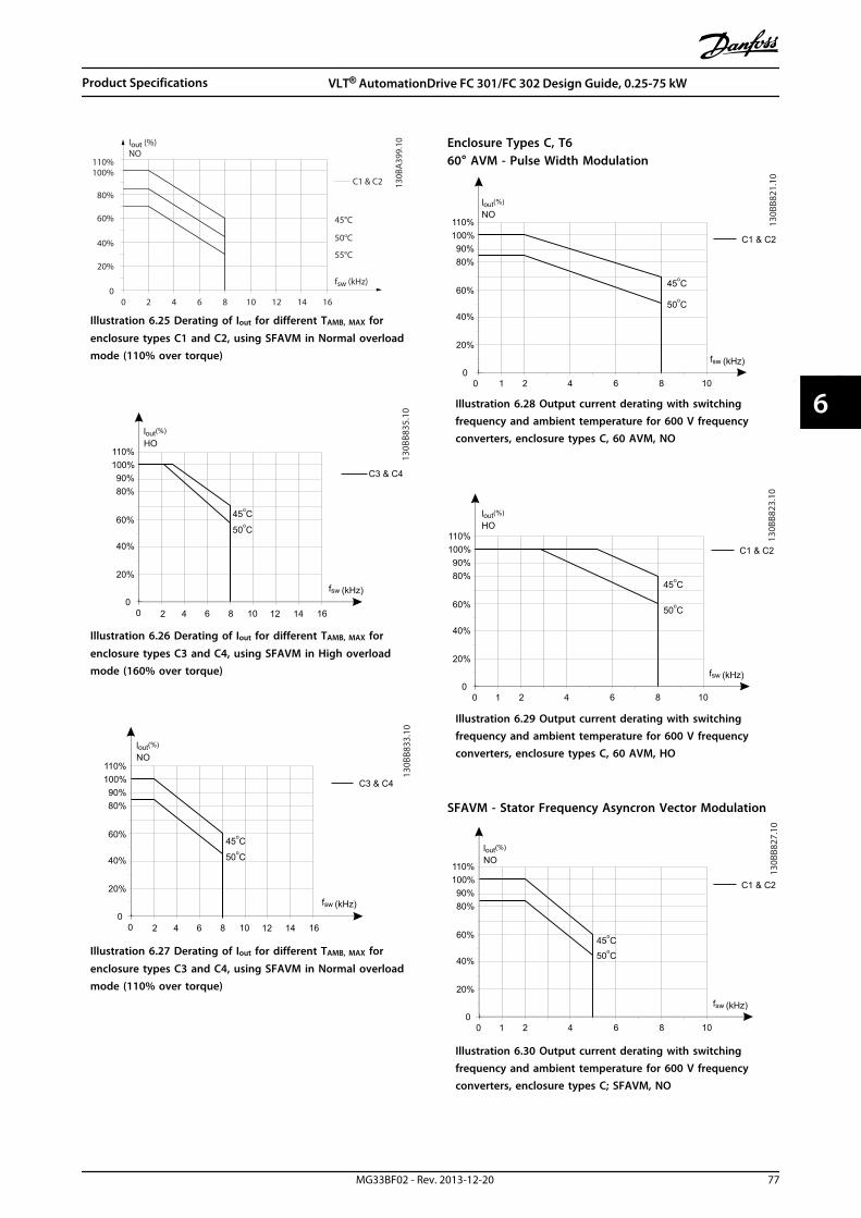
2
20%
4 6 8 10 12 14 16
40%
60%
80%
100%110%
fsw (kHz)
00
Iout (%)NO
45°C
50°C
55°C
130B
A39
9.10
C1 & C2
Illustration 6.25 Derating of Iout for different TAMB, MAX for
enclosure types C1 and C2, using SFAVM in Normal overloadmode (110% over torque)
130B
B835
.10
80%90%
100%110%
C3 & C4
(%)loutHO
2 4 6 8
20%
10
40%
60%o50 C
o45 C
12 14 16
fsw (kHz)
00
Illustration 6.26 Derating of Iout for different TAMB, MAX for
enclosure types C3 and C4, using SFAVM in High overloadmode (160% over torque)
2 4 6 8
20%
10
40%
60%
80%90%
100%
o50 C
o45 C
110%
12 14 16
fsw (kHz)
00
(%)lout
C3 & C4
NO
130B
B833
.10
Illustration 6.27 Derating of Iout for different TAMB, MAX for
enclosure types C3 and C4, using SFAVM in Normal overloadmode (110% over torque)
Enclosure Types C, T660° AVM - Pulse Width Modulation
1 2 4 6 8
20%
10
40%
60%
80%90%
100%
o50 C
o45 C
110%
fsw (kHz)
00
(%)lout
C1 & C2
NO
130B
B821
.10
Illustration 6.28 Output current derating with switchingfrequency and ambient temperature for 600 V frequencyconverters, enclosure types C, 60 AVM, NO
80%90%
100%
o45 C
110%
(%)lout
C1 & C2
HO
1 2 4 6 8
20%
10
40%
60% o50 C
fsw (kHz)
00
130B
B823
.10
Illustration 6.29 Output current derating with switchingfrequency and ambient temperature for 600 V frequencyconverters, enclosure types C, 60 AVM, HO
SFAVM - Stator Frequency Asyncron Vector Modulation
1 2 4 6 8
20%
10
40%
60%
80%90%
100%
o50 C
o45 C
110%
fsw (kHz)
00
(%)lout
C1 & C2
NO
130B
B827
.10
Illustration 6.30 Output current derating with switchingfrequency and ambient temperature for 600 V frequencyconverters, enclosure types C; SFAVM, NO
Product Specifications VLT® AutomationDrive FC 301/FC 302 Design Guide, 0.25-75 kW
MG33BF02 - Rev. 2013-12-20 77
6 6
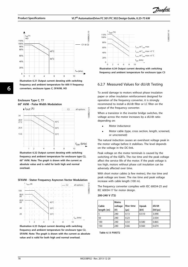
130B
B825
.10
1 2 4 6 8
20%
10
40%
60%
80%90%
100%
o50 C
o45 C
110%
fsw (kHz)
00
(%)lout
C1 & C2
HO
Illustration 6.31 Output current derating with switchingfrequency and ambient temperature for 600 V frequencyconverters, enclosure types C; SFAVM, HO
Enclosure Type C, T760° AVM - Pulse Width Modulation
fsw (kHz)
130B
B213
.11
20.4
34
Iout (A)
28.9
1 2 64
55°C
50°C
45°C
8 10
C2 all options
13.6
27.2
Illustration 6.32 Output current derating with switchingfrequency and ambient temperature for enclosure type C2,
60° AVM. Note: The graph is drawn with the current asabsolute value and is valid for both high and normaloverload.
SFAVM - Stator Frequency Asyncron Vector Modulation
fsw (kHz)
130B
B214
.10
40
60
80
100
Iout (A)
86.6
1 2 64
55°C
50°C
45°C
8 10
C2 all options
66.6
20
Illustration 6.33 Output current derating with switchingfrequency and ambient temperature for enclosure type C2,SFAVM. Note: The graph is drawn with the current as absolutevalue and is valid for both high and normal overload.
2
20%
4 6 8 10
40%
60%
80%
100%110%
Iout (%)
fsw (kHz)
ILOAD
at TAMB
max
130B
D59
7.10
00
ILOAD
at TAMB
max +5 °C
ILOAD
at TAMB
max +5 °C
Illustration 6.34 Output current derating with switchingfrequency and ambient temperature for enclosure type C3
6.2.7 Measured Values for dU/dt Testing
To avoid damage to motors without phase insulationpaper or other insulation reinforcement designed foroperation of the frequency converter, it is stronglyrecommend to install a dU/dt filter or LC filter on theoutput of the frequency converter.
When a transistor in the inverter bridge switches, thevoltage across the motor increases by a dU/dt ratiodepending on:
• Motor inductance
• Motor cable (type, cross section, length, screened,or unscreened)
The natural induction causes an overshoot voltage peak inthe motor voltage before it stabilises. The level dependson the voltage in the DC-link.
Peak voltage on the motor terminals is caused by theswitching of the IGBTs. The rise time and the peak voltageaffect the service life of the motor. If the peak voltage istoo high, motors without phase coil insulation can beadversely affected over time.
With short motor cables (a few metres), the rise time andpeak voltage are lower. The rise time and peak voltageincrease with cable length (100 m).
The frequency converter complies with IEC 60034-25 andIEC 60034-17 for motor design.
200-240 V (T2)
Cablelength [m]
Mainsvoltage[V]
Rise time
[μs]Upeak[kV]
dU/dt
[kV/μs]
5 240 0.13 0.510 3.090
50 240 0.23 2.034
100 240 0.54 0.580 0.865
150 240 0.66 0.560 0.674
Table 6.13 P5K5T2
Product Specifications VLT® AutomationDrive FC 301/FC 302 Design Guide, 0.25-75 kW
78 MG33BF02 - Rev. 2013-12-20
66

Cablelength [m]
Mainsvoltage[V]
Rise time
[μs]Upeak[kV] dU/dt [kV/μs]
36 240 0.264 0.624 1.890
136 240 0.536 0.596 0.889
150 240 0.568 0.568 0.800
Table 6.14 P7K5T2
Cablelength [m]
Mainsvoltage[V]
Rise time
[μs]Upeak[kV]
dU/dt
[kV/μs]
30 240 0.556 0.650 0.935
100 240 0.592 0.594 0.802
150 240 0.708 0.587 0.663
Table 6.15 P11KT2
Cablelength [m]
Mainsvoltage[V]
Rise time
[μs]Upeak[kV]
dU/dt
[kV/μs]
36 240 0.244 0.608 1.993
136 240 0.568 0.580 0.816
150 240 0.720 0.574 0.637
Table 6.16 P15KT2
Cablelength [m]
Mainsvoltage[V]
Rise time
[μs]Upeak[kV]
dU/dt
[kV/μs]
36 240 0.244 0.608 1.993
136 240 0.568 0.580 0.816
150 240 0.720 0.574 0.637
Table 6.17 P18KT2
Cablelength [m]
Mainsvoltage[V]
Rise time
[μs]Upeak[kV]
dU/dt
[kV/μs]
15 240 0.194 0.626 2.581
50 240 0.252 0.574 1.822
150 240 0.488 0.538 0.882
Table 6.18 P22KT2
Cablelength [m]
Mainsvoltage[V]
Rise time
[μs]Upeak[kV]
dU/dt
[kV/μs]
30 240 0.300 0.598 1.594
100 240 0.536 0.566 0.844
150 240 0.776 0.546 0.562
Table 6.19 P30KT2
Cablelength [m]
Mainsvoltage[V]
Rise time
[μs]Upeak[kV]
dU/dt
[kV/μs]
30 240 0.300 0.598 1.594
100 240 0.536 0.566 0.844
150 240 0.776 0.546 0.562
Table 6.20 P37KT2
380-500 V (T4)
Cablelength [m]
Mainsvoltage[V]
Rise time
[μs]Upeak[kV]
dU/dt
[kV/μs]
5 480 0.640 0.690 0.862
50 480 0.470 0.985 0.985
150 480 0.760 1.045 0.947
Table 6.21 P1K5T4
Cablelength [m]
Mainsvoltage[V]
Rise time
[μs]Upeak[kV]
dU/dt
[kV/μs]
5 480 0.172 0.890 4.156
50 480 0.310 2.564
150 480 0.370 1.190 1.770
Table 6.22 P4K0T4
Cablelength [m]
Mainsvoltage[V]
Rise time
[μs]Upeak[kV]
dU/dt
[kV/μs]
5 480 0.04755 0.739 8.035
50 480 0.207 4.548
150 480 0.6742 1.030 2.828
Table 6.23 P7K5T4
Cablelength [m]
Mainsvoltage[V]
Rise time
[μs]Upeak[kV]
dU/dt
[kV/μs]
36 480 0.396 1.210 2.444
100 480 0.844 1.230 1.165
150 480 0.696 1.160 1.333
Table 6.24 P11KT4
Cablelength [m]
Mainsvoltage[V]
Rise time
[μs]Upeak[kV]
dU/dt
[kV/μs]
36 480 0.396 1.210 2.444
100 480 0.844 1.230 1.165
150 480 0.696 1.160 1.333
Table 6.25 P15KT4
Product Specifications VLT® AutomationDrive FC 301/FC 302 Design Guide, 0.25-75 kW
MG33BF02 - Rev. 2013-12-20 79
6 6
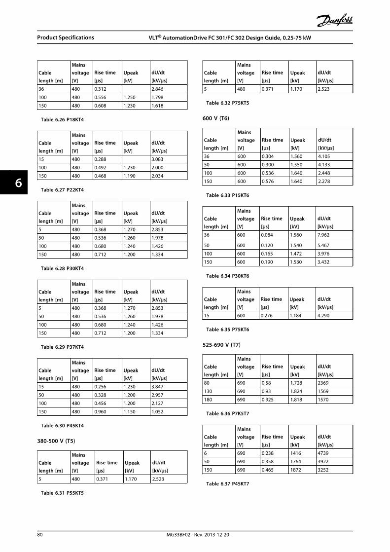
Cablelength [m]
Mainsvoltage[V]
Rise time
[μs]Upeak[kV]
dU/dt
[kV/μs]
36 480 0.312 2.846
100 480 0.556 1.250 1.798
150 480 0.608 1.230 1.618
Table 6.26 P18KT4
Cablelength [m]
Mainsvoltage[V]
Rise time
[μs]Upeak[kV]
dU/dt
[kV/μs]
15 480 0.288 3.083
100 480 0.492 1.230 2.000
150 480 0.468 1.190 2.034
Table 6.27 P22KT4
Cablelength [m]
Mainsvoltage[V]
Rise time
[μs]Upeak[kV]
dU/dt
[kV/μs]
5 480 0.368 1.270 2.853
50 480 0.536 1.260 1.978
100 480 0.680 1.240 1.426
150 480 0.712 1.200 1.334
Table 6.28 P30KT4
Cablelength [m]
Mainsvoltage[V]
Rise time
[μs]Upeak[kV]
dU/dt
[kV/μs]
5 480 0.368 1.270 2.853
50 480 0.536 1.260 1.978
100 480 0.680 1.240 1.426
150 480 0.712 1.200 1.334
Table 6.29 P37KT4
Cablelength [m]
Mainsvoltage[V]
Rise time
[μs]Upeak[kV]
dU/dt
[kV/μs]
15 480 0.256 1.230 3.847
50 480 0.328 1.200 2.957
100 480 0.456 1.200 2.127
150 480 0.960 1.150 1.052
Table 6.30 P45KT4
380-500 V (T5)
Cablelength [m]
Mainsvoltage[V]
Rise time
[μs]Upeak[kV]
dU/dt
[kV/μs]
5 480 0.371 1.170 2.523
Table 6.31 P55KT5
Cablelength [m]
Mainsvoltage[V]
Rise time
[μs]Upeak[kV]
dU/dt
[kV/μs]
5 480 0.371 1.170 2.523
Table 6.32 P75KT5
600 V (T6)
Cablelength [m]
Mainsvoltage[V]
Rise time
[μs]Upeak[kV]
dU/dt
[kV/μs]
36 600 0.304 1.560 4.105
50 600 0.300 1.550 4.133
100 600 0.536 1.640 2.448
150 600 0.576 1.640 2.278
Table 6.33 P15KT6
Cablelength [m]
Mainsvoltage[V]
Rise time
[μs]Upeak[kV]
dU/dt
[kV/μs]
36 600 0.084 1.560 7.962
50 600 0.120 1.540 5.467
100 600 0.165 1.472 3.976
150 600 0.190 1.530 3.432
Table 6.34 P30KT6
Cablelength [m]
Mainsvoltage[V]
Rise time
[μs]Upeak[kV]
dU/dt
[kV/μs]
15 600 0.276 1.184 4.290
Table 6.35 P75KT6
525-690 V (T7)
Cablelength [m]
Mainsvoltage[V]
Rise time
[μs]Upeak[kV]
dU/dt
[kV/μs]
80 690 0.58 1.728 2369
130 690 0.93 1.824 1569
180 690 0.925 1.818 1570
Table 6.36 P7K5T7
Cablelength [m]
Mainsvoltage[V]
Rise time
[μs]Upeak[kV]
dU/dt
[kV/μs]
6 690 0.238 1416 4739
50 690 0.358 1764 3922
150 690 0.465 1872 3252
Table 6.37 P45KT7
Product Specifications VLT® AutomationDrive FC 301/FC 302 Design Guide, 0.25-75 kW
80 MG33BF02 - Rev. 2013-12-20
66

6.2.8 Efficiency
Efficiency of the frequency converterThe load on the frequency converter has little effect on itsefficiency.
This also means that the frequency converter efficiencydoes not change when other U/f characteristics are chosen.However, the U/f characteristics do influence the efficiencyof the motor.
The efficiency declines a little when the switchingfrequency is set to a value above 5 kHz. The efficiency isalso slightly reduced when the motor cable is longer than30 m.
Efficiency calculationCalculate the efficiency of the frequency converter atdifferent loads based on Illustration 6.35. Multiply the factorin this graph with the specific efficiency factor listed in chapter 6.2 General Specifications.
1.0
0.990.98
0.97
0.960.95
0.93
0.920% 50% 100% 200%
0.94Rela
tive
Eci
ency
130B
B252
.111.01
150%% Speed
100% load 75% load 50% load 25% load
Illustration 6.35 Typical Efficiency Curves
Example: Assume a 55 kW, 380-480 V AC frequencyconverter with 25% load at 50% speed. The graph isshowing 0.97 rated efficiency for a 55 kW frequencyconverter is 0.98. The actual efficiency is then: 0.97 x0.98=0.95.
Motor efficiencyThe efficiency of a motor connected to the frequencyconverter depends on magnetising level. The efficiency ofthe motor depends on the type of motor.
• In the range of 75-100% of the rated torque, theefficiency of the motor is practically constant,both when it is controlled by the frequencyconverter and when it runs directly on mains.
• The influence from the U/f characteristic on smallmotors is marginal. However, in motors from 11kW and up, the efficiency advantage is significant.
• The switching frequency does not affect theefficiency of small motors. Motors from 11 kWand up have their efficiency improved 1-2%. Thisis because the sine shape of the motor current isalmost perfect at high switching frequency.
System efficiencyTo calculate the system efficiency, the efficiency of thefrequency converter is multiplied by the efficiency of themotor.
6.2.9 Acoustic Noise
Acoustic noise from the frequency converter comes from 3sources
• DC-link (intermediate circuit) coils
• RFI filter choke
• Internal fans
See Table 6.38 for acoustic noise ratings.
Enclosure type50% fan speed
[dBA]Full fan speed
[dBA]A1 51 60
A2 51 60
A3 51 60
A4 51 60
A5 54 63
B1 61 67
B2 58 70
B4 52 62
C1 52 62
C2 55 65
C4 56 71
D3h 58 71
Table 6.38 Acoustic Noise Ratings
Values are measured 1 m from the unit.
Product Specifications VLT® AutomationDrive FC 301/FC 302 Design Guide, 0.25-75 kW
MG33BF02 - Rev. 2013-12-20 81
6 6
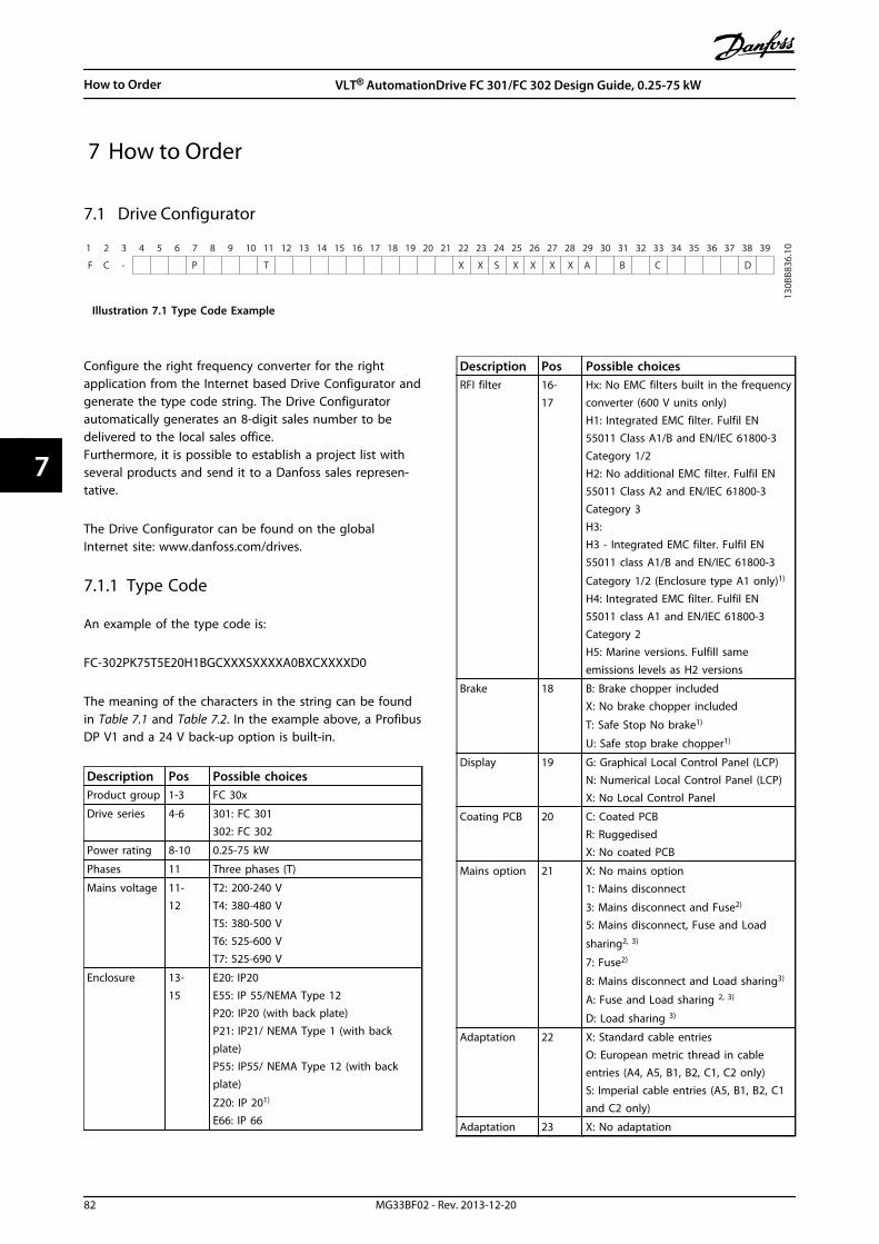
7 How to Order
7.1 Drive Configurator
F C - P T
130B
B836
.10
X S A B CX X X X
1 2 3 4 5 6 7 8 9 10 11 12 13 14 15 16 17 18 19 20 302221 23 272524 26 28 29 31 373635343332 38 39
X D
Illustration 7.1 Type Code Example
Configure the right frequency converter for the rightapplication from the Internet based Drive Configurator andgenerate the type code string. The Drive Configuratorautomatically generates an 8-digit sales number to bedelivered to the local sales office.Furthermore, it is possible to establish a project list withseveral products and send it to a Danfoss sales represen-tative.
The Drive Configurator can be found on the globalInternet site: www.danfoss.com/drives.
7.1.1 Type Code
An example of the type code is:
FC-302PK75T5E20H1BGCXXXSXXXXA0BXCXXXXD0
The meaning of the characters in the string can be foundin Table 7.1 and Table 7.2. In the example above, a ProfibusDP V1 and a 24 V back-up option is built-in.
Description Pos Possible choicesProduct group 1-3 FC 30x
Drive series 4-6 301: FC 301302: FC 302
Power rating 8-10 0.25-75 kW
Phases 11 Three phases (T)
Mains voltage 11-12
T2: 200-240 VT4: 380-480 VT5: 380-500 VT6: 525-600 VT7: 525-690 V
Enclosure 13-15
E20: IP20E55: IP 55/NEMA Type 12P20: IP20 (with back plate)P21: IP21/ NEMA Type 1 (with backplate)P55: IP55/ NEMA Type 12 (with backplate)
Z20: IP 201)
E66: IP 66
Description Pos Possible choicesRFI filter 16-
17Hx: No EMC filters built in the frequencyconverter (600 V units only)H1: Integrated EMC filter. Fulfil EN55011 Class A1/B and EN/IEC 61800-3Category 1/2H2: No additional EMC filter. Fulfil EN55011 Class A2 and EN/IEC 61800-3Category 3H3:H3 - Integrated EMC filter. Fulfil EN55011 class A1/B and EN/IEC 61800-3
Category 1/2 (Enclosure type A1 only)1)
H4: Integrated EMC filter. Fulfil EN55011 class A1 and EN/IEC 61800-3Category 2H5: Marine versions. Fulfill sameemissions levels as H2 versions
Brake 18 B: Brake chopper includedX: No brake chopper included
T: Safe Stop No brake1)
U: Safe stop brake chopper1)
Display 19 G: Graphical Local Control Panel (LCP)N: Numerical Local Control Panel (LCP)X: No Local Control Panel
Coating PCB 20 C: Coated PCBR: RuggedisedX: No coated PCB
Mains option 21 X: No mains option1: Mains disconnect
3: Mains disconnect and Fuse2)
5: Mains disconnect, Fuse and Load
sharing2, 3)
7: Fuse2)
8: Mains disconnect and Load sharing3)
A: Fuse and Load sharing 2, 3)
D: Load sharing 3)
Adaptation 22 X: Standard cable entriesO: European metric thread in cableentries (A4, A5, B1, B2, C1, C2 only)S: Imperial cable entries (A5, B1, B2, C1and C2 only)
Adaptation 23 X: No adaptation
How to Order VLT® AutomationDrive FC 301/FC 302 Design Guide, 0.25-75 kW
82 MG33BF02 - Rev. 2013-12-20
77
Description Pos Possible choicesSoftwarerelease
24-27
SXXX: Latest release - standard software
Softwarelanguage
28 X: Not used
1): FC 301/enclosure type A1 only2) US Market only3): A and B3 frames have load-sharing built-in by default
Table 7.1 Ordering Type Code Enclosure types A, Band C
Description Pos Possible choicesA options 29-
30AX: No A optionA0: MCA 101 Profibus DP V1 (standard)A4: MCA 104 DeviceNet (standard)A6: MCA 105 CANOpen (standard)AN: MCA 121 Ethernet IPAL: MCA 120 ProfiNetAQ: MCA 122 Modbus TCPAT: MCA 113 Profibus converter VLT3000AU: MCA 114 Profibus Converter VLT5000AY: MCA 123 PowerlinkA8: MCA 124 EtherCAT
B options 31-32
BX: No optionBK: MCB 101 General purpose I/OoptionBR: MCB 102 Encoder optionBU: MCB 103 Resolver optionBP: MCB 105 Relay optionBZ: MCB 108 Safety PLC InterfaceB2: MCB 112 PTC Thermistor CardB4: MCB 114 VLT Sensor InputB6: MCB 150 Safe Option TTLB7: MCB 151 Safe Option HTL
C0 options 33-34
CX: No optionC4: MCO 305, Programmable MotionController
C1 options 35 X: No optionR: MCB 113 Ext. Relay CardZ: MCA 140 Modbus RTU OEM option
C optionsoftware/E1options
36-37
XX: Standard controller10: MCO 350 Synchronizing control11: MCO 351 Positioning control
D options 38-39
DX: No optionD0: MCB 107 Ext. 24 V DC back-up
Table 7.2 Ordering Type Code, Options
NOTICEFor power sizes over 75 kW, see the VLT®
AutomationDrive FC 300 90-1400 kW Design Guide.
How to Order VLT® AutomationDrive FC 301/FC 302 Design Guide, 0.25-75 kW
MG33BF02 - Rev. 2013-12-20 83
7 7

7.1.2 Language
Frequency converters are automatically delivered with a language package relevant to the region from which it is ordered. 4regional language packages cover the following languages:
Language package 1 Language package 2 Language package 3 Language package 4
English English English English
German German German German
French Chinese Slovenian Spanish
Danish Korean Bulgarian English US
Dutch Japanese Serbian Greek
Spanish Thai Romanian Brazilian Portuguese
Swedish Traditional Chinese Hungarian Turkish
Italian Bahasa Indonesian Czech Polish
Finnish Russian
Table 7.3 Language Packages
To order frequency converters with a different language package, contact the local sales office.
How to Order VLT® AutomationDrive FC 301/FC 302 Design Guide, 0.25-75 kW
84 MG33BF02 - Rev. 2013-12-20
77

7.2 Ordering Numbers
7.2.1 Options and Accessories
Description Ordering no.Uncoated Coated
Miscellaneous hardware
VLT® Panel through kit enclosure type A5 130B1028
VLT® Panel through kit enclosure type B1 130B1046
VLT® Panel through kit enclosure type B2 130B1047
VLT® Panel through kit enclosure type C1 130B1048
VLT® Panel through kit enclosure type C2 130B1049
VLT® Mounting brackets for enclosure type A5 130B1080
VLT® Mounting brackets for enclosure type B1 130B1081
VLT® Mounting brackets for enclosure type B2 130B1082
VLT® Mounting brackets for enclosure type C1 130B1083
VLT® Mounting brackets for enclosure type C2 130B1084
VLT® IP 21/Type 1 Kit, enclosure type A1 130B1121
VLT® IP 21/Type 1 Kit, enclosure type A2 130B1122
VLT® IP 21/Type 1 Kit, enclosure type A3 130B1123
VLT® IP 21/Type 1 Top Kit, enclosure type A2 130B1132
VLT® IP 21/Type 1 Top Kit, enclosure type A3 130B1133
VLT® Back plate IP55/Type12, enclosure type A5 130B1098
VLT® Back plate IP21/Type 1, IP55/Type 12, enclosure type B1 130B3383
VLT® Back plate IP21/Type 1, IP55/Type 12, enclosure type B2 130B3397
VLT® Back plate IP20/Type 1, enclosure type B4 130B4172
VLT® Back plate IP21/Type 1, IP55/Type 12, enclosure type C1 130B3910
VLT® Back plate IP21/Type 1, IP55/Type 12, enclosure type C2 130B3911
VLT® Back plate IP20/Type 1, enclosure type C3 130B4170
VLT® Back plate IP20/Type 1, enclosure type C4 130B4171
VLT® Back plate IP66/Type 4X, enclosure type A5 130B3242
VLT® Back plate in stainless steel IP66/Type 4X, enclosure type B1 130B3434
VLT® Back plate in stainless steel IP66/Type 4X, enclosure type B2 130B3465
VLT® Back plate in stainless steel IP66/Type 4X, enclosure type C1 130B3468
VLT® Back plate in stainless steel IP66/Type 4X, enclosure type C2 130B3491
VLT® Profibus Adapter Sub-D9 Connector 130B1112
Profibus screen plate kit for IP20, enclosure types A1, A2 and A3 130B0524
Terminal block for DC link connection on enclosure types A2/A3 130B1064
VLT® Screw terminals 130B1116
VLT® USB extension, 350 mm cable 130B1155
VLT® USB extension, 650 mm cable 130B1156
VLT® Back frame A2 for 1 brakeresistor 175U0085
VLT® Back frame A3 for 1 brakeresistor 175U0088
VLT® Back frame A2 for 2 brake resistors 175U0087
VLT® Back A3 for 2 brake resistors 175U0086
Local Control Panel
VLT® LCP 101 Numeric Local Contral Pad 130B1124
VLT® LCP 102 Graphical Local Control Pad 130B1107
VLT® Cable for LCP 2, 3 m 175Z0929
VLT® Panel Mounting Kit for all LCP types 130B1170
VLT® Panel Mounting Kit, graphical LCP 130B1113
How to Order VLT® AutomationDrive FC 301/FC 302 Design Guide, 0.25-75 kW
MG33BF02 - Rev. 2013-12-20 85
7 7

Description Ordering no.Uncoated Coated
VLT® Panel Mounting Kit, numerical LCP 130B1114
VLT® LCP Mounting Kit, w/ no LCP 130B1117
VLT® LCP Mounting Kit Blind Cover IP55/66, 8 m 130B1129
VLT® Control Panel LCP 102, graphical 130B1078
VLT® Blindcover, w/ Danfoss logo, IP55/66 130B1077
Options for slot A
VLT® Profibus DP V1 MCA 101 130B1100 130B1200
VLT® DeviceNet MCA 104 130B1102 130B1202
VLT® CAN Open MCA 105 130B1103 130B1205
VLT® PROFIBUS Converter MCA 113 130B1245
VLT® PROFIBUS Converter MCA 114 130B1246
VLT® PROFINET MCA 120 130B1135 130B1235
VLT® EtherNet/IP MCA 121 130B1119 130B1219
VLT® Modbus TCP MCA 122 130B1196 130B1296
POWERLINK 130B1489 130B1490
EtherCAT 130B5546 130B5646
VLT® DeviceNet MCA 104 130B1102 130B1202
Options for slot B
VLT® General Purpose I/O MCB 101 130B1125 130B1212
VLT® Encoder Input MCB 102 130B1115 130B1203
VLT® Resolver Input MCB 103 130B1127 130B1227
VLT® Relay Option MCB 105 130B1110 130B1210
VLT® Safe PLC I/O MCB 108 130B1120 130B1220
VLT® PTC Thermistor Card MCB 112 130B1137
VLT® Safe Option MCB 140 130B6443
VLT® Safe Option MCB 141 130B6447
VLT® Safe option MCB 150 130B3280
VLT® Safe option MCB 151 130B3290
Mounting Kits for C options
VLT® Mounting Kit for C Option, 40 mm, enclosure types A2/A3 130B7530
VLT® Mounting Kit for C Option, 60 mm, enclosure types A2/A3 130B7531
VLT® Mounting Kit for C Option, enclosure type A5 130B7532
VLT® Mounting Kit for C Option, enclosure types B/C/D/E/F (except B3) 130B7533
VLT® Mounting Kit for C Option, 40 mm, enclosure type B3 130B1413
VLT® Mounting Kit for C Option, 60 mm, enclosure type B3 130B1414
Options for Slot C
VLT® Motion Control MCO 305 130B1134 130B1234
VLT® Synchronizing Contr. MCO 350 130B1152 130B1252
VLT® Position. Controller MCO 351 130B1153 120B1253
Center Winder Controller 130B1165 130B1166
VLT® Extended Relay Card MCB 113 130B1164 130B1264
VLT® C Option Adapter MCF 106 130B1230
Option for Slot D
VLT® 24 V DC Supply MCB 107 130B1108 130B1208
VLT® EtherNet/IP MCA 121 175N2584
VLT® Leakage Current Monitor Kit, enclosure types A2/A3 130B5645
VLT® Leakage Current Monitor Kit, enclosure type B3 130B5764
VLT® Leakage Current Monitor Kit, enclosure type B4 130B5765
VLT® Leakage Current Monitor Kit, enclosure type C3 130B6226
How to Order VLT® AutomationDrive FC 301/FC 302 Design Guide, 0.25-75 kW
86 MG33BF02 - Rev. 2013-12-20
77
Description Ordering no.Uncoated Coated
VLT® Leakage Current Monitor Kit, enclosure type C4 130B5647
PC Software
VLT® Motion Ctrl Tool MCT 10, 1 license 130B1000
VLT® Motion Ctrl Tool MCT 10, 5 licenses 130B1001
VLT® Motion Ctrl Tool MCT 10, 10 licenses 130B1002
VLT® Motion Ctrl Tool MCT 10, 25 licenses 130B1003
VLT® Motion Ctrl Tool MCT 10, 50 licenses 130B1004
VLT® Motion Ctrl Tool MCT 10, 100 licenses 130B1005
VLT® Motion Ctrl Tool MCT 10, >100 licenses 130B1006
Options can be ordered as factory built-in options, see ordering information, chapter 7.1 Drive Configurator.
Table 7.4 Ordering Numbers for Options and Accessories
7.2.2 Spare Parts
Consult the VLT shop or the configurator for spare parts available for your specification,VLTShop.danfoss.com.
7.2.3 Accessory Bags
Type Description Ordering no.
Accessory Bags
Accessory bag A1 Accessory bag, enclosure type A1 130B1021
Accessory bag A2/A3 Accessory bag, enclosure type A2/A3 130B1022
Accessory bag A5 Accessory bag, enclosure type A5 130B1023
Accessory bag A1–A5 Accessory bag, enclosure type A1-A5 Brake and load sharing connector 130B0633
Accessory bag B1 Accessory bag, enclosure type B1 130B2060
Accessory bag B2 Accessory bag, enclosure type B2 130B2061
Accessory bag B3 Accessory bag, enclosure type B3 130B0980
Accessory bag B4 Accessory bag, enclosure type B4, 18.5-22 kW 130B1300
Accessory bag B4 Accessory bag, enclosure type B4, 30 kW 130B1301
Accessory bag C1 Accessory bag, enclosure type C1 130B0046
Accessory bag C2 Accessory bag, enclosure type C2 130B0047
Accessory bag C3 Accessory bag, enclosure type C3 130B0981
Accessory bag C4 Accessory bag, enclosure type C4, 55 kW 130B0982
Accessory bag C4 Accessory bag, enclosure type C4, 75 kW 130B0983
Table 7.5 Ordering Numbers for Accessory Bags
How to Order VLT® AutomationDrive FC 301/FC 302 Design Guide, 0.25-75 kW
MG33BF02 - Rev. 2013-12-20 87
7 7

7.2.4 VLT AutomationDrive FC 301
T2, Horizontal Braking 10% Duty CycleFC 301 Horizontal braking 10% duty cycle
Frequency converter dataBrake resistor data Installation
Rrec
[Ω]
Pbr.cont.
[kW]
Danfoss part number Cablecross
section
[mm2]
Thermorelay
[A]
Mainstype
Pm
[kW]
Rmin
[Ω]
Rbr.nom
[Ω] Wire IP54Screw
terminalIP21
Screwterminal
IP65
Boltconnection
IP20
T2 0.25 368 415.9 410 0.100 175u3004 - - - 1.5 0.5
T2 0.37 248 280.7 300 0.100 175u3006 - - - 1.5 0.6
T2 0.55 166 188.7 200 0.100 175u3011 - - - 1.5 0.7
T2 0.75 121 138.4 145 0.100 175u3016 - - - 1.5 0.8
T2 1.1 81.0 92.0 100 0.100 175u3021 - - - 1.5 0.9
T2 1.5 58.5 66.5 70 0.200 175u3026 - - - 1.5 1.6
T2 2.2 40.2 44.6 48 0.200 175u3031 - - - 1.5 1.9
T2 3 29.1 32.3 35 0.300 175u3325 - - - 1.5 2.7
T2 3.7 22.5 25.9 27 0.360 175u3326 175u3477 175u3478 - 1.5 3.5
T2 5.5 17.7 19.7 18 0.570 175u3327 175u3442 175u3441 - 1.5 5.3
T2 7.5 12.6 14.3 13 0.680 175u3328 175u3059 175u3060 - 1.5 6.8
T2 11 8.7 9.7 9 1.130 175u3329 175u3068 175u3069 - 2.5 10.5
T2 15 5.3 7.5 5.7 1.400 175u3330 175u3073 175u3074 - 4 15
T2 18.5 5.1 6.0 5.7 1.700 175u3331 175u3483 175u3484 - 4 16
T2 22 3.2 5.0 3.5 2.200 175u3332 175u3080 175u3081 - 6 24
T2 30 3.0 3.7 3.5 2.800 175u3333 175u3448 175u3447 - 10 27
T2 37 2.4 3.0 2.8 3.200 175u3334 175u3086 175u3087 - 16 32
Table 7.6 T2, Horizontal Braking 10% Duty Cycle
How to Order VLT® AutomationDrive FC 301/FC 302 Design Guide, 0.25-75 kW
88 MG33BF02 - Rev. 2013-12-20
77
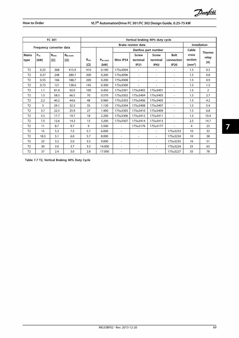
FC 301 Vertical braking 40% duty cycle
Frequency converter dataBrake resistor data Installation
Rrec
[Ω]Pbr.cont.
[kW]
Danfoss part number Cablecross
section
[mm2]
Thermorelay
[A]
Mainstype
Pm
[kW]
Rmin
[Ω]
Rbr.nom
[Ω] Wire IP54Screw
terminalIP21
Screwterminal
IP65
Boltconnection
IP20
T2 0.25 368 415.9 410 0.100 175u3004 - - - 1.5 0.5
T2 0.37 248 280.7 300 0.200 175u3096 - - - 1.5 0.8
T2 0.55 166 188.7 200 0.200 175u3008 - - - 1.5 0.9
T2 0.75 121 138.4 145 0.300 175u3300 - - - 1.5 1.3
T2 1.1 81.0 92.0 100 0.450 175u3301 175u3402 175u3401 - 1.5 2
T2 1.5 58.5 66.5 70 0.570 175u3302 175u3404 175u3403 - 1.5 2.7
T2 2.2 40.2 44.6 48 0.960 175u3303 175u3406 175u3405 - 1.5 4.2
T2 3 29.1 32.3 35 1.130 175u3304 175u3408 175u3407 - 1.5 5.4
T2 3.7 22.5 25.9 27 1.400 175u3305 175u3410 175u3409 - 1.5 6.8
T2 5.5 17.7 19.7 18 2.200 175u3306 175u3412 175u3411 - 1.5 10.4
T2 7.5 12.6 14.3 13 3.200 175u3307 175u3414 175u3413 - 2.5 14.7
T2 11 8.7 9.7 9 5.500 - 175u3176 175u3177 - 4 23
T2 15 5.3 7.5 5.7 6.000 - - - 175u3233 10 33
T2 18.5 5.1 6.0 5.7 8.000 - - - 175u3234 10 38
T2 22 3.2 5.0 3.5 9.000 - - - 175u3235 16 51
T2 30 3.0 3.7 3.5 14.000 - - - 175u3224 25 63
T2 37 2.4 3.0 2.8 17.000 - - - 175u3227 35 78
Table 7.7 T2, Vertical Braking 40% Duty Cycle
How to Order VLT® AutomationDrive FC 301/FC 302 Design Guide, 0.25-75 kW
MG33BF02 - Rev. 2013-12-20 89
7 7

FC 301 Horizontal braking 10% duty cycle
Frequency converter dataBrake resistor data Installation
Rrec
[Ω]Pbr.cont.
[kW]
Danfoss part number Cablecross
section
[mm2]
Thermorelay
[A]
Mainstype
Pm
[kW]
Rmin
[Ω]
Rbr.nom
[Ω] Wire IP54Screw
terminalIP21
Screwterminal
IP65
Boltconnection
IP20
T4 0.37 1000 1121.4 1200 0.100 175u3000 - - - 1.5 0.3
T4 0.55 620 749.8 850 0.100 175u3001 - - - 1.5 0.4
T4 0.75 485 547.6 630 0.100 175u3002 - - - 1.5 0.4
T4 1.1 329 365.3 410 0.100 175u3004 - - - 1.5 0.5
T4 1.5 240 263.0 270 0.200 175u3007 - - - 1.5 0.8
T4 2.2 161 176.5 200 0.200 175u3008 - - - 1.5 0.9
T4 3 117 127.9 145 0.300 175u3300 - - - 1.5 1.3
T4 4 86.9 94.6 110 0.450 175u3335 175u3450 175u3449 - 1.5 1.9
T4 5.5 62.5 68.2 80 0.570 175u3336 175u3452 175u3451 - 1.5 2.5
T4 7.5 45.3 49.6 56 0.680 175u3337 175u3027 175u3028 - 1.5 3.3
T4 11 34.9 38.0 38 1.130 175u3338 175u3034 175u3035 - 1.5 5.2
T4 15 25.3 27.7 28 1.400 175u3339 175u3039 175u3040 - 1.5 6.7
T4 18.5 20.3 22.3 22 1.700 175u3340 175u3047 175u3048 - 1.5 8.3
T4 22 16.9 18.7 19 2.200 175u3357 175u3049 175u3050 - 1.5 10.1
T4 30 13.2 14.5 14 2.800 175u3341 175u3055 175u3056 - 2.5 13.3
T4 37 10.6 11.7 12 3.200 175u3359 175u3061 175u3062 - 2.5 15.3
T4 45 8.7 9.6 9.5 4.200 - 175u3065 175u3066 - 4 20
T4 55 6.6 7.8 7.0 5.500 - 175u3070 175u3071 - 6 26
T4 75 4.2 5.7 5.5 7.000 - - - 175u3231 10 36
Table 7.8 T4, Horizontal Braking 10% Duty Cycle
How to Order VLT® AutomationDrive FC 301/FC 302 Design Guide, 0.25-75 kW
90 MG33BF02 - Rev. 2013-12-20
77

FC 301 Vertical braking 40% duty cycle
Frequency converter dataBrake resistor data Installation
Rrec
[Ω]Pbr.cont.
[kW]
Danfoss part number Cablecross
section
[mm2]
Thermorelay
[A]
Mainstype
Pm
[kW]
Rmin
[Ω]
Rbr.nom
[Ω] Wire IP54Screw
terminalIP21
Screwterminal
IP65
Boltconnection
IP20
T4 0.37 1000 1121.4 1200 0.200 175u3101 - - - 1.5 0.4
T4 0.55 620 749.8 850 0.200 175u3308 - - - 1.5 0.5
T4 0.75 485 547.6 630 0.300 175u3309 - - - 1.5 0.7
T4 1.1 329 365.3 410 0.450 175u3310 175u3416 175u3415 - 1.5 1
T4 1.5 240 263.0 270 0.570 175u3311 175u3418 175u3417 - 1.5 1.4
T4 2.2 161 176.5 200 0.960 175u3312 175u3420 175u3419 - 1.5 2.1
T4 3 117 127.9 145 1.130 175u3313 175u3422 175u3421 - 1.5 2.7
T4 4 86.9 94.6 110 1.700 175u3314 175u3424 175u3423 - 1.5 3.7
T4 5.5 62.5 68.2 80 2.200 175u3315 175u3138 175u3139 - 1.5 5
T4 7.5 45.3 49.6 56 3.200 175u3316 175u3428 175u3427 - 1.5 7.1
T4 11 34.9 38.0 38 5.000 - - - 175u3236 1.5 11.5
T4 15 25.3 27.7 28 6.000 - - - 175u3237 2.5 14.7
T4 18.5 20.3 22.3 22 8.000 - - - 175u3238 4 19
T4 22 16.9 18.7 19 10.000 - - - 175u3203 4 23
T4 30 13.2 14.5 14 14.000 - - - 175u3206 10 32
T4 37 10.6 11.7 12 17.000 - - - 175u3210 10 38
T4 45 8.7 9.6 9.5 21.000 - - - 175u3213 16 47
T4 55 6.6 7.8 7.0 26.000 - - - 175u3216 25 61
T4 75 4.2 5.7 5.5 36.000 - - - 175u3219 35 81
Table 7.9 T4, Vertical Braking 40% Duty Cycle
How to Order VLT® AutomationDrive FC 301/FC 302 Design Guide, 0.25-75 kW
MG33BF02 - Rev. 2013-12-20 91
7 7
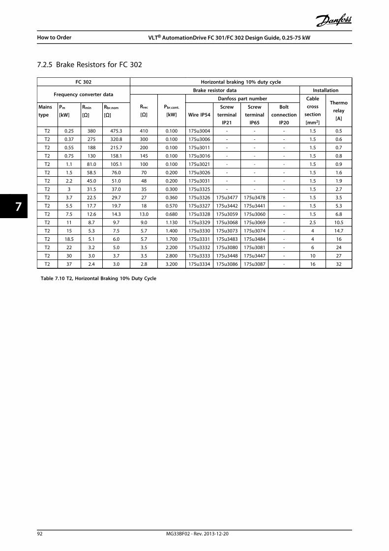
7.2.5 Brake Resistors for FC 302
FC 302 Horizontal braking 10% duty cycle
Frequency converter dataBrake resistor data Installation
Rrec
[Ω]
Pbr.cont.
[kW]
Danfoss part number Cablecross
section
[mm2]
Thermorelay
[A]
Mainstype
Pm
[kW]
Rmin
[Ω]
Rbr.nom
[Ω] Wire IP54Screw
terminalIP21
Screwterminal
IP65
Boltconnection
IP20
T2 0.25 380 475.3 410 0.100 175u3004 - - - 1.5 0.5
T2 0.37 275 320.8 300 0.100 175u3006 - - - 1.5 0.6
T2 0.55 188 215.7 200 0.100 175u3011 - - - 1.5 0.7
T2 0.75 130 158.1 145 0.100 175u3016 - - - 1.5 0.8
T2 1.1 81.0 105.1 100 0.100 175u3021 - - - 1.5 0.9
T2 1.5 58.5 76.0 70 0.200 175u3026 - - - 1.5 1.6
T2 2.2 45.0 51.0 48 0.200 175u3031 - - - 1.5 1.9
T2 3 31.5 37.0 35 0.300 175u3325 - - - 1.5 2.7
T2 3.7 22.5 29.7 27 0.360 175u3326 175u3477 175u3478 - 1.5 3.5
T2 5.5 17.7 19.7 18 0.570 175u3327 175u3442 175u3441 - 1.5 5.3
T2 7.5 12.6 14.3 13.0 0.680 175u3328 175u3059 175u3060 - 1.5 6.8
T2 11 8.7 9.7 9.0 1.130 175u3329 175u3068 175u3069 - 2.5 10.5
T2 15 5.3 7.5 5.7 1.400 175u3330 175u3073 175u3074 - 4 14.7
T2 18.5 5.1 6.0 5.7 1.700 175u3331 175u3483 175u3484 - 4 16
T2 22 3.2 5.0 3.5 2.200 175u3332 175u3080 175u3081 - 6 24
T2 30 3.0 3.7 3.5 2.800 175u3333 175u3448 175u3447 - 10 27
T2 37 2.4 3.0 2.8 3.200 175u3334 175u3086 175u3087 - 16 32
Table 7.10 T2, Horizontal Braking 10% Duty Cycle
How to Order VLT® AutomationDrive FC 301/FC 302 Design Guide, 0.25-75 kW
92 MG33BF02 - Rev. 2013-12-20
77
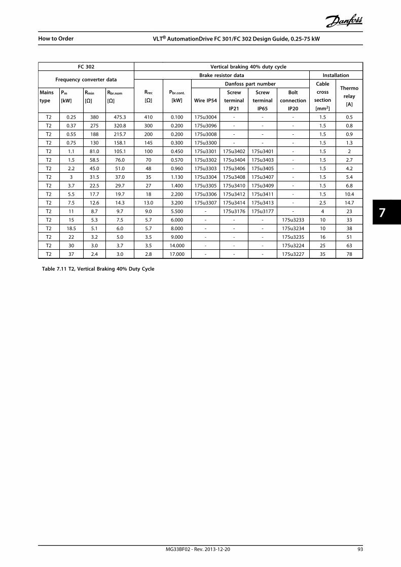
FC 302 Vertical braking 40% duty cycle
Frequency converter dataBrake resistor data Installation
Rrec
[Ω]
Pbr.cont.
[kW]
Danfoss part number Cablecross
section
[mm2]
Thermorelay
[A]
Mainstype
Pm
[kW]
Rmin
[Ω]
Rbr.nom
[Ω] Wire IP54Screw
terminalIP21
Screwterminal
IP65
Boltconnection
IP20
T2 0.25 380 475.3 410 0.100 175u3004 - - - 1.5 0.5
T2 0.37 275 320.8 300 0.200 175u3096 - - - 1.5 0.8
T2 0.55 188 215.7 200 0.200 175u3008 - - - 1.5 0.9
T2 0.75 130 158.1 145 0.300 175u3300 - - - 1.5 1.3
T2 1.1 81.0 105.1 100 0.450 175u3301 175u3402 175u3401 - 1.5 2
T2 1.5 58.5 76.0 70 0.570 175u3302 175u3404 175u3403 - 1.5 2.7
T2 2.2 45.0 51.0 48 0.960 175u3303 175u3406 175u3405 - 1.5 4.2
T2 3 31.5 37.0 35 1.130 175u3304 175u3408 175u3407 - 1.5 5.4
T2 3.7 22.5 29.7 27 1.400 175u3305 175u3410 175u3409 - 1.5 6.8
T2 5.5 17.7 19.7 18 2.200 175u3306 175u3412 175u3411 - 1.5 10.4
T2 7.5 12.6 14.3 13.0 3.200 175u3307 175u3414 175u3413 - 2.5 14.7
T2 11 8.7 9.7 9.0 5.500 - 175u3176 175u3177 - 4 23
T2 15 5.3 7.5 5.7 6.000 - - - 175u3233 10 33
T2 18.5 5.1 6.0 5.7 8.000 - - - 175u3234 10 38
T2 22 3.2 5.0 3.5 9.000 - - - 175u3235 16 51
T2 30 3.0 3.7 3.5 14.000 - - - 175u3224 25 63
T2 37 2.4 3.0 2.8 17.000 - - - 175u3227 35 78
Table 7.11 T2, Vertical Braking 40% Duty Cycle
How to Order VLT® AutomationDrive FC 301/FC 302 Design Guide, 0.25-75 kW
MG33BF02 - Rev. 2013-12-20 93
7 7
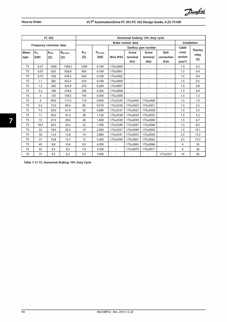
FC 302 Horizontal braking 10% duty cycle
Frequency converter dataBrake resistor data Installation
Rrec
[Ω]
Pbr.cont.
[kW]
Danfoss part number Cablecross
section
[mm2]
Thermorelay
[A]
Mainstype
Pm
[kW]
Rmin
[Ω]
Rbr.nom
[Ω] Wire IP54Screw
terminalIP21
Screwterminal
IP65
Boltconnection
IP20
T5 0.37 1000 1389.2 1200 0.100 175u3000 - - - 1.5 0.3
T5 0.55 620 928.8 850 0.100 175u3001 - - - 1.5 0.4
T5 0.75 558 678.3 630 0.100 175u3002 - - - 1.5 0.4
T5 1.1 382 452.5 410 0.100 175u3004 - - - 1.5 0.5
T5 1.5 260 325.9 270 0.200 175u3007 - - - 1.5 0.8
T5 2.2 189 218.6 200 0.200 175u3008 - - - 1.5 0.9
T5 3 135 158.5 145 0.300 175u3300 - - - 1.5 1.3
T5 4 99.0 117.2 110 0.450 175u3335 175u3450 175u3449 - 1.5 1.9
T5 5.5 72.0 84.4 80 0.570 175u3336 175u3452 175u3451 - 1.5 2.5
T5 7.5 50.0 61.4 56 0.680 175u3337 175u3027 175u3028 - 1.5 3.3
T5 11 36.0 41.2 38 1.130 175u3338 175u3034 175u3035 - 1.5 5.2
T5 15 27.0 30.0 28 1.400 175u3339 175u3039 175u3040 - 1.5 6.7
T5 18.5 20.3 24.2 22 1.700 175u3340 175u3047 175u3048 - 1.5 8.3
T5 22 18.0 20.3 19 2.200 175u3357 175u3049 175u3050 - 1.5 10.1
T5 30 13.4 15.8 14 2.800 175u3341 175u3055 175u3056 - 2.5 13.3
T5 37 10.8 12.7 12 3.200 175u3359 175u3061 175u3062 - 2.5 15.3
T5 45 8.8 10.4 9.5 4.200 - 175u3065 175u3066 - 4 20
T5 55 6.5 8.5 7.0 5.500 - 175u3070 175u3071 - 6 26
T5 75 4.2 6.2 5.5 7.000 - - - 175u3231 10 36
Table 7.12 T5, Horizontal Braking 10% Duty Cycle
How to Order VLT® AutomationDrive FC 301/FC 302 Design Guide, 0.25-75 kW
94 MG33BF02 - Rev. 2013-12-20
77

FC 302 Vertical braking 40% duty cycle
Frequency converter dataBrake resistor data Installation
Rrec
[Ω]
Pbr.cont.
[kW]
Danfoss part number Cablecross
section
[mm2]
Thermorelay
[A]
Mainstype
Pm
[kW]
Rmin
[Ω]
Rbr.nom
[Ω] Wire IP54Screw
terminalIP21
Screwterminal
IP65
Boltconnection
IP20
T5 0.37 1000 1389.2 1200 0.200 175u3101 - - - 1.5 0.4
T5 0.55 620 928.8 850 0.200 175u3308 - - - 1.5 0.5
T5 0.75 558 678.3 630 0.300 175u3309 - - - 1.5 0.7
T5 1.1 382 452.5 410 0.450 175u3310 175u3416 175u3415 - 1.5 1
T5 1.5 260 325.9 270 0.570 175u3311 175u3418 175u3417 - 1.5 1.4
T5 2.2 189 218.6 200 0.960 175u3312 175u3420 175u3419 - 1.5 2.1
T5 3 135 158.5 145 1.130 175u3313 175u3422 175u3421 - 1.5 2.7
T5 4 99.0 117.2 110 1.700 175u3314 175u3424 175u3423 - 1.5 3.7
T5 5.5 72.0 84.4 80 2.200 175u3315 175u3138 175u3139 - 1.5 5
T5 7.5 50.0 61.4 56 3.200 175u3316 175u3428 175u3427 - 1.5 7.1
T5 11 36.0 41.2 38 5.000 - - - 175u3236 1.5 11.5
T5 15 27.0 30.0 28 6.000 - - - 175u3237 2.5 14.7
T5 18.5 20.3 24.2 22 8.000 - - - 175u3238 4 19
T5 22 18.0 20.3 19 10.000 - - - 175u3203 4 23
T5 30 13.4 15.8 14 14.000 - - - 175u3206 10 32
T5 37 10.8 12.7 12 17.000 - - - 175u3210 10 38
T5 45 8.8 10.4 9.5 21.000 - - - 175u3213 16 47
T5 55 6.5 8.5 7.0 26.000 - - - 175u3216 25 61
T5 75 4.2 6.2 5.5 36.000 - - - 175u3219 35 81
Table 7.13 T5, Vertical Braking 40% Duty Cycle
How to Order VLT® AutomationDrive FC 301/FC 302 Design Guide, 0.25-75 kW
MG33BF02 - Rev. 2013-12-20 95
7 7

FC 302 Horizontal braking 10% duty cycle
Frequency converter dataBrake resistor data Installation
Rrec
[Ω]
Pbr.cont.
[kW]
Danfoss part number Cablecross
section
[mm2]
Thermorelay
[A]
Mainstype
Pm
[kW]
Rmin
[Ω]
Rbr.nom
[Ω] Wire IP54Screw
terminalIP21
Screwterminal
IP65
Boltconnection
IP20
T6 0.75 620 914.2 850 0.100 175u3001 - - - 1.5 0.4
T6 1.1 550 611.3 570 0.100 175u3003 - - - 1.5 0.4
T6 1.5 380 441.9 415 0.200 175u3005 - - - 1.5 0.7
T6 2.2 260 296.4 270 0.200 175u3007 - - - 1.5 0.8
T6 3 189 214.8 200 0.300 175u3342 - - - 1.5 1.1
T6 4 135 159.2 145 0.450 175u3343 175u3012 175u3013 - 1.5 1.7
T6 5.5 99.0 114.5 100 0.570 175u3344 175u3136 175u3137 - 1.5 2.3
T6 7.5 69.0 83.2 72 0.680 175u3345 175u3456 175u3455 - 1.5 2.9
T6 11 48.6 56.1 52 1.130 175u3346 175u3458 175u3457 - 1.5 4.4
T6 15 35.1 40.8 38 1.400 175u3347 175u3460 175u3459 - 1.5 5.7
T6 18.5 27.0 32.9 31 1.700 175u3348 175u3037 175u3038 - 1.5 7
T6 22 22.5 27.6 27 2.200 175u3349 175u3043 175u3044 - 1.5 8.5
T6 30 17.1 21.4 19 2.800 175u3350 175u3462 175u3461 - 2.5 11.4
T6 37 13.5 17.3 14 3.200 175u3358 175u3464 175u3463 - 2.5 14.2
T6 45 10.8 14.2 13.5 4.200 - 175u3057 175u3058 - 4 17
T6 55 8.8 11.6 11 5.500 - 175u3063 175u3064 - 6 21
T6 75 6.6 8.4 7.0 7.000 - - - 175u3245 10 32
Table 7.14 T6, Horizontal Braking 10% Duty Cycle
How to Order VLT® AutomationDrive FC 301/FC 302 Design Guide, 0.25-75 kW
96 MG33BF02 - Rev. 2013-12-20
77
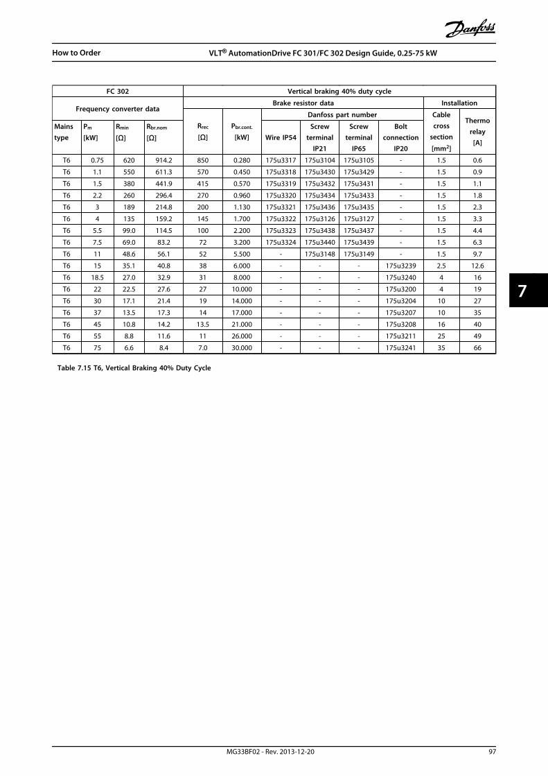
FC 302 Vertical braking 40% duty cycle
Frequency converter dataBrake resistor data Installation
Rrec
[Ω]
Pbr.cont.
[kW]
Danfoss part number Cablecross
section
[mm2]
Thermorelay
[A]
Mainstype
Pm
[kW]
Rmin
[Ω]
Rbr.nom
[Ω] Wire IP54Screw
terminalIP21
Screwterminal
IP65
Boltconnection
IP20
T6 0.75 620 914.2 850 0.280 175u3317 175u3104 175u3105 - 1.5 0.6
T6 1.1 550 611.3 570 0.450 175u3318 175u3430 175u3429 - 1.5 0.9
T6 1.5 380 441.9 415 0.570 175u3319 175u3432 175u3431 - 1.5 1.1
T6 2.2 260 296.4 270 0.960 175u3320 175u3434 175u3433 - 1.5 1.8
T6 3 189 214.8 200 1.130 175u3321 175u3436 175u3435 - 1.5 2.3
T6 4 135 159.2 145 1.700 175u3322 175u3126 175u3127 - 1.5 3.3
T6 5.5 99.0 114.5 100 2.200 175u3323 175u3438 175u3437 - 1.5 4.4
T6 7.5 69.0 83.2 72 3.200 175u3324 175u3440 175u3439 - 1.5 6.3
T6 11 48.6 56.1 52 5.500 - 175u3148 175u3149 - 1.5 9.7
T6 15 35.1 40.8 38 6.000 - - - 175u3239 2.5 12.6
T6 18.5 27.0 32.9 31 8.000 - - - 175u3240 4 16
T6 22 22.5 27.6 27 10.000 - - - 175u3200 4 19
T6 30 17.1 21.4 19 14.000 - - - 175u3204 10 27
T6 37 13.5 17.3 14 17.000 - - - 175u3207 10 35
T6 45 10.8 14.2 13.5 21.000 - - - 175u3208 16 40
T6 55 8.8 11.6 11 26.000 - - - 175u3211 25 49
T6 75 6.6 8.4 7.0 30.000 - - - 175u3241 35 66
Table 7.15 T6, Vertical Braking 40% Duty Cycle
How to Order VLT® AutomationDrive FC 301/FC 302 Design Guide, 0.25-75 kW
MG33BF02 - Rev. 2013-12-20 97
7 7

FC 302 Vertical braking 40% duty cycle
Frequency converter dataBrake resistor data Installation
Rrec
[Ω]
Pbr.cont.
[kW]
Danfoss part number Cablecross
section
[mm2]
Thermorelay
[A]
Mainstype
Pm
[kW]
Rmin
[Ω]
Rbr.nom
[Ω] Wire IP54Screw
terminalIP21
Screwterminal
IP65
Boltconnection
IP20
T7 1.1 620 830 630 0.360 - 175u3108 175u3109 - 1.5 0.8
T7 1.5 513 600 570 0.570 - 175u3110 175u3111 - 1.5 1
T7 2.2 340 403 415 0.790 - 175u3112 175u3113 - 1.5 1.3
T7 3 243 292 270 1.130 - 175u3118 175u3119 - 1.5 2
T7 4 180 216 200 1.700 - 175u3122 175u3123 - 1.5 2.8
T7 5.5 130 156 145 2.200 - 175u3106 175u3107 - 1.5 3.7
T7 7.5 94 113 105 3.200 - 175u3132 175u3133 - 1.5 5.2
T7 11 69.7 76.2 72 4.200 - 175u3142 175u3143 - 1.5 7.2
T7 15 46.8 55.5 52 6.000 - - - 175u3242 2.5 10.8
T7 18.5 36.0 44.7 42 8.000 - - - 175u3243 2.5 13.9
T7 22 29.0 37.5 31 10.000 - - - 175u3244 4 18
T7 30 22.5 29.1 27 14.000 - - - 175u3201 10 23
T7 37 18.0 23.5 22 17.000 - - - 175u3202 10 28
T7 45 13.5 19.3 15.5 21.000 - - - 175u3205 16 37
T7 55 13.5 15.7 13.5 26.000 - - - 175u3209 16 44
T7 75 8.8 11.5 11 36.000 - - - 175u3212 25 57
Table 7.16 T7, Vertical Braking 40% Duty Cycle
Horizontal braking: Duty cycle 10% and maximum 120 s repetition rates according the reference brake profile. Average power corresponds to 6%.Vertical braking: Duty cycle 40% and maximum 120 s repetition rates according the reference brake profile. Average power corresponds to 27%.
Cable cross-section: Recommended min. value based upon PVC-insulated copper cable, 30 °C ambient temperature with normal heat dissipation.All cabling must comply with national and local regulations on cable cross-sections and ambient temperature.Thermal relay: Brake current setting of external thermal relay. All resistors have a built-in thermal relay switch N.C.The IP54 is with 1,000 mm fixed unscreened cable. Vertical and horizontal mounting. Derating required by horizontal mounting.IP21 & IP65 are with screw terminal for cable termination. Vertical and horizontal mounting. Derating required by horizontal mounting.The IP20 is with bolt connection for cable termination. Floor mounting.
150/160%
175U
A06
7.10
Illustration 7.2 Horizontal Loads
100%
150/160%
175U
A06
8.10
Illustration 7.3 Vertical Loads
How to Order VLT® AutomationDrive FC 301/FC 302 Design Guide, 0.25-75 kW
98 MG33BF02 - Rev. 2013-12-20
77

7.2.6 Other Flat Pack Brake Resistors
FC 301 Pm Rmin Rbr, nom
Flat pack IP65 for horizontal conveyors
Rrec per item Duty cycle Ordering no.
T2 [kW] [Ω] [Ω] [Ω//W] [%] 175Uxxxx
PK25 0.25 368 416 430/100 40 1002
PK37 0.37 248 281 330/100 or 310/200 27 or 55 1003 or 0984
PK55 0.55 166 189 220/100 or 210/200 20 or 37 1004 or 0987
PK75 0.75 121 138 150/100 or 150/200 14 or 27 1005 or 0989
P1K1 1.1 81.0 92 100/100 or 100/200 10 or 19 1006 or 0991
P1K5 1.5 58.5 66.5 72/200 14 0992
P2K2 2.2 40.2 44.6 50/200 10 0993
P3K0 3 29.1 32.3 35/200 or 72/200 7 14 0994 or 2 x 0992
P3K7 3.7 22.5 25.9 60/200 11 2 x 0996
Table 7.17 Other Flat Packs for Frequency Converters with Mains SupplyFC 301 Mains: 200-240 V (T2)
FC 302 Pm Rmin Rbr. nom
Flat pack IP65 for horizontal conveyors
Rrec per item Duty cycle Ordering no.
T2 [kW] [Ω] [Ω] [Ω/W] [%] 175Uxxxx
PK25 0.25 380 475 430/100 40 1002
PK37 0.37 275 321 330/100 or 310/200 27 or 55 1003 or 0984
PK55 0.55 188 216 220/100 or 210/200 20 or 37 1004 or 0987
PK75 0.75 130 158 150/100 or 150/200 14 or 27 1005 or 0989
P1K1 1.1 81.0 105.1 100/100 or 100/200 10 or 19 1006 or 0991
P1K5 1.5 58.5 76.0 72/200 14 0992
P2K2 2.2 45.0 51.0 50/200 10 0993
P3K0 3 31.5 37.0 35/200 or 72/200 7 or 14 0994 or 2 x 0992
P3K7 3.7 22.5 29.7 60/200 11 2 x 0996
Table 7.18 Other Flat Packs for Frequency Converters with Mains SupplyFC 302 Mains: 200-240 V (T2)
FC 301 Pm Rmin Rbr. nom
Flat pack IP65 for horizontal conveyors
Rrec per item Duty cycle Ordering no.
T4 [kW] [Ω] [Ω] [Ω/W] [%] 175Uxxxx
PK37 0.37 620 1121 830/100 30 1000
PK55 0.55 620 750 830/100 20 1000
PK75 0.75 485 548 620/100 or 620/200 14 or 27 1001 or 0982
P1K1 1.1 329 365 430/100 or 430/200 10 or 20 1002 or 0983
P1K5 1.5 240.0 263.0 310/200 14 0984
P2K2 2.2 161.0 176.5 210/200 10 0987
P3K0 3 117.0 127.9 150/200 or 300/200 7 or 14 0989 or 2 x 0985
P4K0 4 87 95 240/200 10 2 x 0986
P5K5 5.5 63 68 160/200 8 2 x 0988
P7K5 7.5 45 50 130/200 6 2 x 0990
P11K 11 34.9 38.0 80/240 5 2 x 0090
P15K 15 25.3 27.7 72/240 4 2 x 0091
Table 7.19 Other Flat Packs for Frequency Converters with Mains SupplyFC 301 Mains: 380-480 V (T4)
How to Order VLT® AutomationDrive FC 301/FC 302 Design Guide, 0.25-75 kW
MG33BF02 - Rev. 2013-12-20 99
7 7
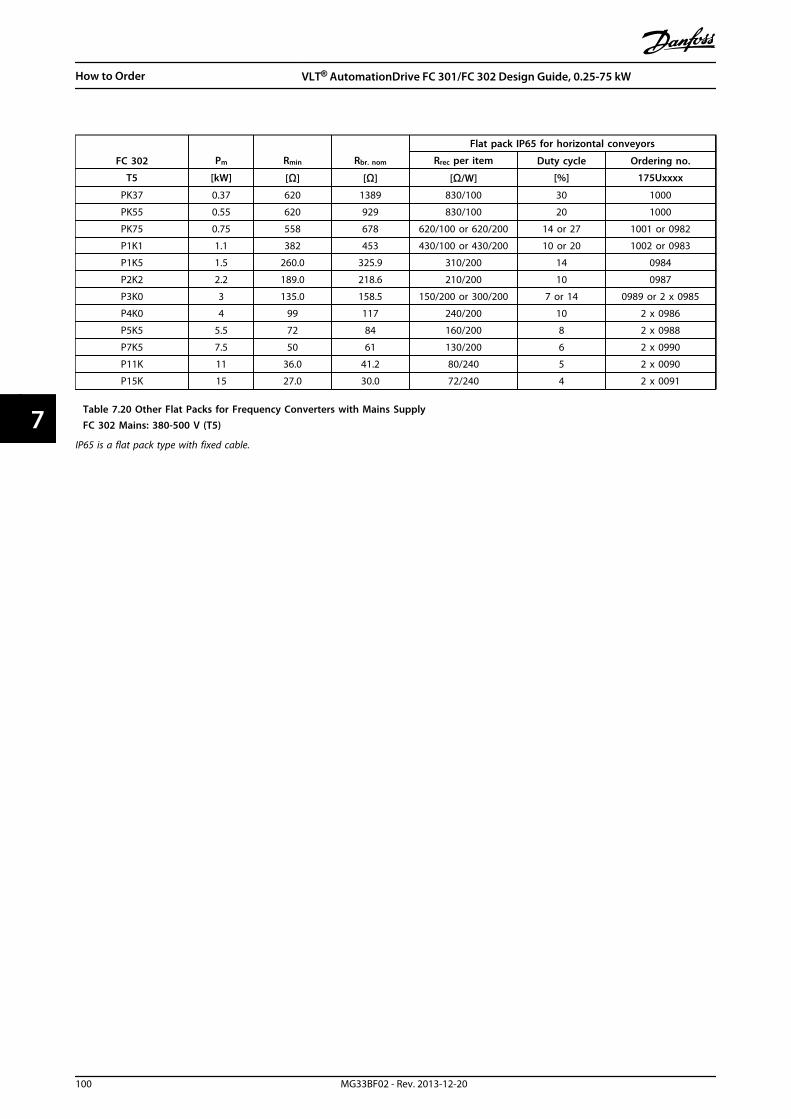
FC 302 Pm Rmin Rbr. nom
Flat pack IP65 for horizontal conveyors
Rrec per item Duty cycle Ordering no.
T5 [kW] [Ω] [Ω] [Ω/W] [%] 175Uxxxx
PK37 0.37 620 1389 830/100 30 1000
PK55 0.55 620 929 830/100 20 1000
PK75 0.75 558 678 620/100 or 620/200 14 or 27 1001 or 0982
P1K1 1.1 382 453 430/100 or 430/200 10 or 20 1002 or 0983
P1K5 1.5 260.0 325.9 310/200 14 0984
P2K2 2.2 189.0 218.6 210/200 10 0987
P3K0 3 135.0 158.5 150/200 or 300/200 7 or 14 0989 or 2 x 0985
P4K0 4 99 117 240/200 10 2 x 0986
P5K5 5.5 72 84 160/200 8 2 x 0988
P7K5 7.5 50 61 130/200 6 2 x 0990
P11K 11 36.0 41.2 80/240 5 2 x 0090
P15K 15 27.0 30.0 72/240 4 2 x 0091
Table 7.20 Other Flat Packs for Frequency Converters with Mains SupplyFC 302 Mains: 380-500 V (T5)
IP65 is a flat pack type with fixed cable.
How to Order VLT® AutomationDrive FC 301/FC 302 Design Guide, 0.25-75 kW
100 MG33BF02 - Rev. 2013-12-20
77
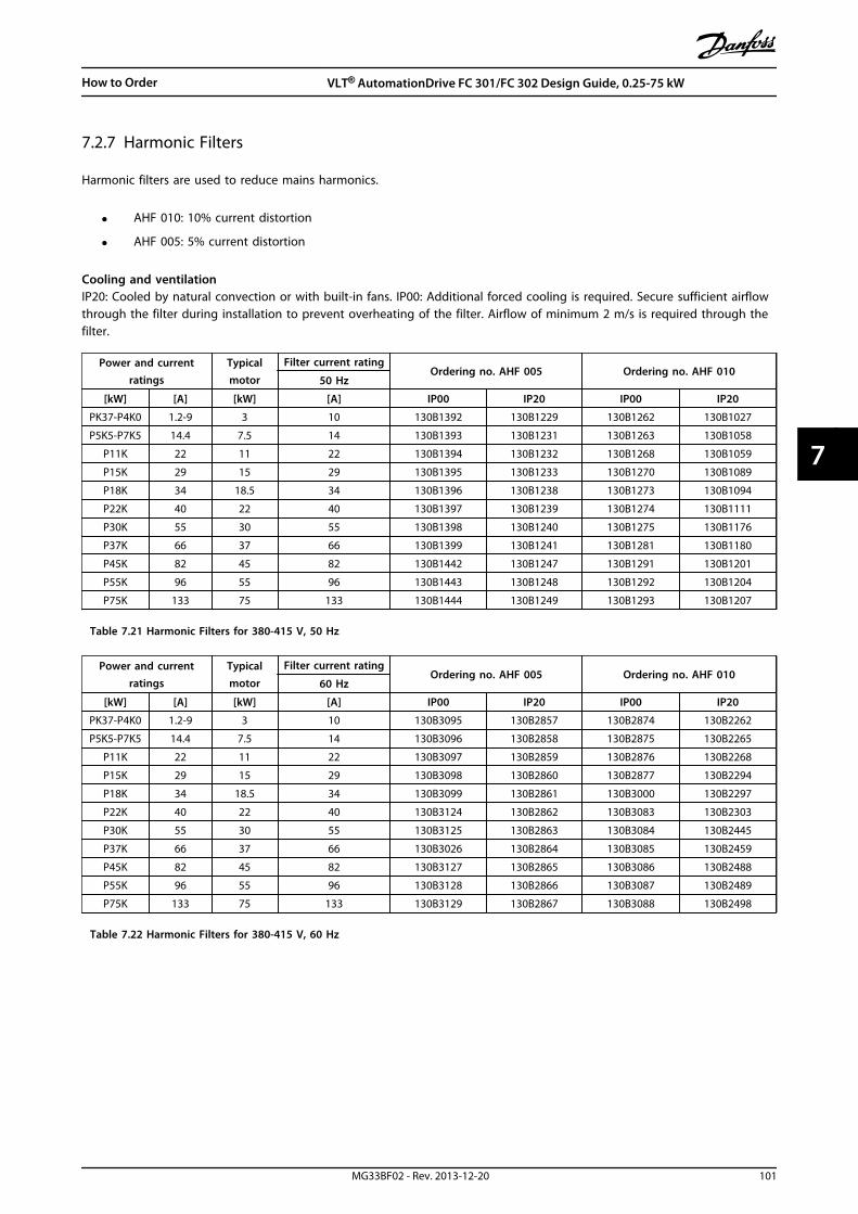
7.2.7 Harmonic Filters
Harmonic filters are used to reduce mains harmonics.
• AHF 010: 10% current distortion
• AHF 005: 5% current distortion
Cooling and ventilationIP20: Cooled by natural convection or with built-in fans. IP00: Additional forced cooling is required. Secure sufficient airflowthrough the filter during installation to prevent overheating of the filter. Airflow of minimum 2 m/s is required through thefilter.
Power and currentratings
Typicalmotor
Filter current ratingOrdering no. AHF 005 Ordering no. AHF 010
50 Hz
[kW] [A] [kW] [A] IP00 IP20 IP00 IP20
PK37-P4K0 1.2-9 3 10 130B1392 130B1229 130B1262 130B1027
P5K5-P7K5 14.4 7.5 14 130B1393 130B1231 130B1263 130B1058
P11K 22 11 22 130B1394 130B1232 130B1268 130B1059
P15K 29 15 29 130B1395 130B1233 130B1270 130B1089
P18K 34 18.5 34 130B1396 130B1238 130B1273 130B1094
P22K 40 22 40 130B1397 130B1239 130B1274 130B1111
P30K 55 30 55 130B1398 130B1240 130B1275 130B1176
P37K 66 37 66 130B1399 130B1241 130B1281 130B1180
P45K 82 45 82 130B1442 130B1247 130B1291 130B1201
P55K 96 55 96 130B1443 130B1248 130B1292 130B1204
P75K 133 75 133 130B1444 130B1249 130B1293 130B1207
Table 7.21 Harmonic Filters for 380-415 V, 50 Hz
Power and currentratings
Typicalmotor
Filter current ratingOrdering no. AHF 005 Ordering no. AHF 010
60 Hz
[kW] [A] [kW] [A] IP00 IP20 IP00 IP20
PK37-P4K0 1.2-9 3 10 130B3095 130B2857 130B2874 130B2262
P5K5-P7K5 14.4 7.5 14 130B3096 130B2858 130B2875 130B2265
P11K 22 11 22 130B3097 130B2859 130B2876 130B2268
P15K 29 15 29 130B3098 130B2860 130B2877 130B2294
P18K 34 18.5 34 130B3099 130B2861 130B3000 130B2297
P22K 40 22 40 130B3124 130B2862 130B3083 130B2303
P30K 55 30 55 130B3125 130B2863 130B3084 130B2445
P37K 66 37 66 130B3026 130B2864 130B3085 130B2459
P45K 82 45 82 130B3127 130B2865 130B3086 130B2488
P55K 96 55 96 130B3128 130B2866 130B3087 130B2489
P75K 133 75 133 130B3129 130B2867 130B3088 130B2498
Table 7.22 Harmonic Filters for 380-415 V, 60 Hz
How to Order VLT® AutomationDrive FC 301/FC 302 Design Guide, 0.25-75 kW
MG33BF02 - Rev. 2013-12-20 101
7 7

Power and currentratings
Typicalmotor
Filter current ratingOrdering no. AHF 005 Ordering no. AHF 010
60 Hz
[kW] [A] [kW] [A] IP00 IP20 IP00 IP20
PK37-P4K0 1-7.4 3 10 130B1787 130B1752 130B1770 130B1482
P5K5-P7K5 9.9+13 7.5 14 130B1788 130B1753 130B1771 130B1483
P11K 19 11 19 130B1789 130B1754 130B1772 130B1484
P15K 25 15 25 130B1790 130B1755 130B1773 130B1485
P18K 31 18.5 31 130B1791 130B1756 130B1774 130B1486
P22K 36 22 36 130B1792 130B1757 130B1775 130B1487
P30K 47 30 48 130B1793 130B1758 130B1776 130B1488
P37K 59 37 60 130B1794 130B1759 130B1777 130B1491
P45K 73 45 73 130B1795 130B1760 130B1778 130B1492
P55K 95 55 95 130B1796 130B1761 130B1779 130B1493
P75K 118 75 118 130B1797 130B1762 130B1780 130B1494
Table 7.23 Harmonic Filters for 440-480 V, 60 Hz
Power and currentratings
Typicalmotor
Filter current ratingOrdering no. AHF 005 Ordering no. AHF 010
60 Hz
[kW] [A] [kW] [A] IP00 IP20 IP00 IP20
P11K 15 10 15 130B5261 130B5246 130B5229 130B5212
P15K 19 16.4 20 130B5262 130B5247 130B5230 130B5213
P18K 24 20 24 130B5263 130B5248 130B5231 130B5214
P22K 29 24 29 130B5263 130B5248 130B5231 130B5214
P30K 36 33 36 130B5265 130B5250 130B5233 130B5216
P37K 49 40 50 130B5266 130B5251 130B5234 130B5217
P45K 58 50 58 130B5267 130B5252 130B5235 130B5218
P55K 74 60 77 130B5268 130B5253 130B5236 130B5219
P75K 85 75 87 130B5269 130B5254 130B5237 130B5220
Table 7.24 Harmonic Filters for 600 V, 60 Hz
Power andcurrent ratings
Typicalmotor
Power and CurrentRatings
Typicalmotor
Filter currentrating Ordering no. AHF 005 Ordering no. AHF 010
500-550 V 551-690 V 50 Hz
[kW] [A] [kW] [kW] [A] [kW] [A] IP00 IP20 IP00 IP20
P11K 15 7.5 P15K 16 15 15 130B5000 130B5088 130B5297 130B5280
P15K 19.5 11 P18K 20 18.5 20 130B5017 130B5089 130B5298 130B5281
P18K 24 15 P22K 25 22 24 130B5018 130B5090 130B5299 130B5282
P22K 29 18.5 P30K 31 30 29 130B5019 130B5092 130B5302 130B5283
P30K 36 22 P37K 38 37 36 130B5021 130B5125 130B5404 130B5284
P37K 49 30 P45K 48 45 50 130B5022 130B5144 130B5310 130B5285
P45K 59 37 P55K 57 55 58 130B5023 130B5168 130B5324 130B5286
P55K 71 45 P75K 76 75 77 130B5024 130B5169 130B5325 130B5287
P75K 89 55 87 130B5025 130B5170 130B5326 130B5288
Table 7.25 Harmonic Filters for 500-690 V, 50 Hz
How to Order VLT® AutomationDrive FC 301/FC 302 Design Guide, 0.25-75 kW
102 MG33BF02 - Rev. 2013-12-20
77

7.2.8 Sine-Wave Filters
Frequency converter power and current ratings Filter current ratingSwitchingfrequency
Ordering no.
200-240 V 380-440 V 441-500 V 50 Hz 60 Hz 100 Hz IP00 IP20/231)
[kW] [A] [kW] [A] [kW] [A] [A] [A] [A] [kHz]
- - 0.37 1.3 0.37 1.1
2.5 2.5 2 5 130B2404 130B24390.25 1.8 0.55 1.8 0.55 1.6
0.37 2.4 0.75 2.4 0.75 2.1
1.1 3 1.1 34.5 4 3.5 5 130B2406 130B2441
0.55 3.5 1.5 4.1 1.5 3.4
0.75 4.6 2.2 5.6 2.2 4.8
8 7.5 5.5 5 130B2408 130B24431.1 6.6 3 7.2 3 6.3
1.5 7.5 - - - -
- - 4 10 4 8.2 10 9.5 7.5 5 130B2409 130B2444
2.2 10.6 5.5 13 5.5 11
17 16 13 5 130B2411 130B24463 12.5 7.5 16 7.5 14.5
3.7 16.7 - - - -
5.5 24.2 11 24 11 21 24 23 18 4 130B2412 130B2447
7.5 30.815 32 15 27
38 36 28.5 4 130B2413 130B244818.5 37.5 18.5 34
11 46.2 22 44 22 40 48 45.5 36 4 130B2281 130B2307
15 59.4 30 61 30 52 62 59 46.5 3 130B2282 130B2308
18.5 74.8 37 73 37 65 75 71 56 3 130B2283 130B2309
22 88 45 90 55 80115 109 86 3 130B3179 130B3181*
30 115 55 106 75 105
37 143 75 14790 130 180 170 135 3 130B3182 130B3183*
45 170 90 177
Table 7.26 Sine-Wave Filters for Frequency Converters with 380-500 V
1) Ordering numbers marked with * are IP23.
How to Order VLT® AutomationDrive FC 301/FC 302 Design Guide, 0.25-75 kW
MG33BF02 - Rev. 2013-12-20 103
7 7

Frequency converter power and current ratings Filter current ratingSwitchingfrequency
Ordering no.
525-600 V 690 V 525-550 V 50 Hz 60 Hz 100 Hz IP00 IP20/231)
[kW] [A] [kW] [A] [kW] [A] [A] [A] [A] kHz
0.75 1.7 1.1 1.6
- - 4.5 4 3 4 130B7335 130B73561.1 2.4 1.5 2.2
1.5 2.7 2.2 3.2
2.2 3.9 3.0 4.5
3 4.9 4.0 5.5
- - 10 9 7 4 130B7289 130B73244 6.1 5.5 7.5
5.5 9 7.5 10
7.5 11 11 13 7.5 14 13 12 9 3 130B3195 130B3196
11 18 15 18 11 19
28 26 21 3 130B4112 130B411315 22 18.5 22 15 23
18.5 27 22 27 18 28
22 34 30 34 22 3645 42 33 3 130B4114 130B4115
30 41 37 41 30 48
37 52 45 52 37 5476 72 57 3 130B4116 130B4117*
45 62 55 62 45 65
55 83 75 83 55 87115 109 86 3 130B4118 130B4119*
75 100 90 100 75 105
90 131 - - 90 137 165 156 124 2 130B4121 130B4124*
Table 7.27 Sine-Wave Filters for Frequency Converters with 525-690 V
1) Ordering numbers marked with * are IP23.
Parameter Setting14-00 Switching Pattern [1] SFAVM
14-01 Switching Frequency Set according the individual filter. Listed at filter product label and in output filter manual. Sine-wavefilters are not allowing lower switching frequency than specified by the individual filter.
14-55 Output Filter [2] Sine-Wave Filter Fixed
14-56 Capacitance OutputFilter
Set according to the individual filter. Listed at filter product label and in output filter manual (onlyrequired for FLUX operation).
14-57 Inductance Output Filter Set according to the individual filter. Listed at filter product label and in output filter manual (onlyrequired for FLUX operation).
Table 7.28 Parameter Settings for Sine-wave Filter Operation
How to Order VLT® AutomationDrive FC 301/FC 302 Design Guide, 0.25-75 kW
104 MG33BF02 - Rev. 2013-12-20
77

7.2.9 dU/dt FiltersFr
eque
ncy
conv
erte
r ra
tings
[V]
Filte
r cu
rren
t ra
ting
[V]
Ord
erin
g n
o.
200-
240
380-
440
441-
500
525-
550
551-
690
380@
60 H
z20
0-40
0/44
0@50
Hz
460/
480
@60
Hz
500/
525
@50
Hz
575/
600
@60
Hz
690
@50
Hz
IP00
IP20
*IP
54
[kW
][A
][k
W]
[A]
[kW
][A
][k
W]
[A]
[kW
][A
][A
][A
][A
][A
]
312
.55.
513
5.5
115.
59.
51.
11.
6
1715
1310
N/A
130B
7367
*N
/A
3.7
167.
516
7.5
14.5
7.5
11.5
1.5
2.2
--
--
--
--
2.2
3.2
34.
5
45.
5
5.5
7.5
7.5
10
5.5
24.2
1124
1121
7,5
1411
13
4440
3227
130B
2835
130B
2836
130B
2837
7.5
30.8
1532
1527
1119
1518
--
18.5
37.5
18.5
3415
2318
.522
--
2244
2240
18,5
2822
27
1146
.230
6130
5230
4330
34
9080
5854
130B
2838
130B
2839
130B
2840
1559
.437
7337
6537
5437
41
18.5
74.8
4590
5580
4565
4552
2288
--
--
--
--
--
5510
675
105
5587
5562
106
105
9486
103B
2841
103B
2842
103B
2843
--
7583
3011
575
147
9013
075
113
9010
8
177
160
131
108
130B
2844
130B
2845
130B
2846
3714
390
177
--
9013
7-
-
4517
0-
--
--
--
-
* D
edic
ated
A3
encl
osur
e ty
pes
supp
ortin
g fo
ot p
rint
mou
ntin
g a
nd b
ook
styl
e m
ount
ing.
Fix
ed s
cree
ned
cab
le c
onne
ctio
n t
o fr
eque
ncy
conv
erte
r.
Tabl
e 7.
29 d
U/d
t Fi
lters
for
200-
690
V
How to Order VLT® AutomationDrive FC 301/FC 302 Design Guide, 0.25-75 kW
MG33BF02 - Rev. 2013-12-20 105
7 7
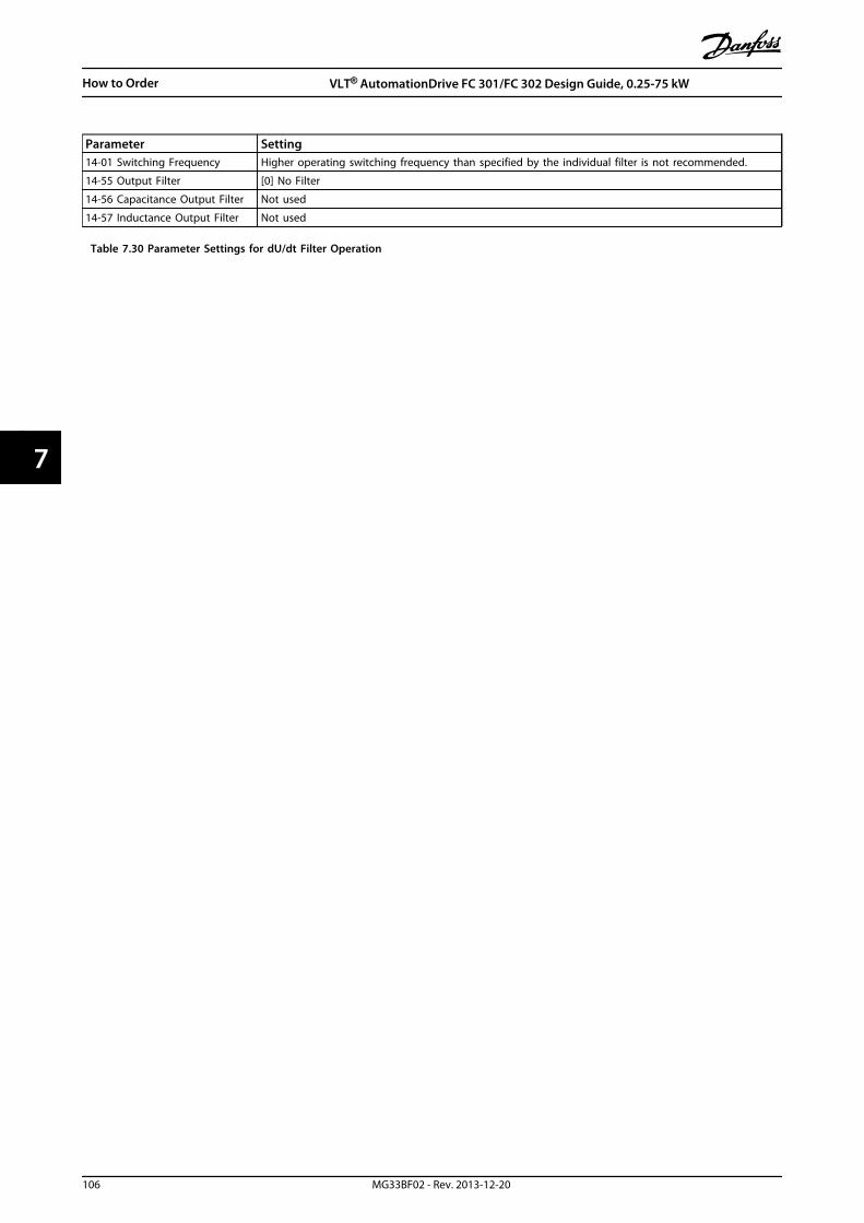
Parameter Setting14-01 Switching Frequency Higher operating switching frequency than specified by the individual filter is not recommended.
14-55 Output Filter [0] No Filter
14-56 Capacitance Output Filter Not used
14-57 Inductance Output Filter Not used
Table 7.30 Parameter Settings for dU/dt Filter Operation
How to Order VLT® AutomationDrive FC 301/FC 302 Design Guide, 0.25-75 kW
106 MG33BF02 - Rev. 2013-12-20
77

8 Mechanical Installation
8.1 Safety
See chapter 2 Safety for general safety instructions.
WARNINGPay attention to the requirements that apply tointegration and field mounting kit. Observe theinformation in the list to avoid serious injury orequipment damage, especially when installing largeunits.
NOTICEThe frequency converter is cooled by means of aircirculation.To protect the unit from overheating, it must be ensuredthat the ambient temperature does NOT exceed themaximum temperature stated for the frequencyconverter and that the 24-hour average temperature isNOT exceeded. Locate the maximum temperature inchapter 6.2.3 Ambient Conditions. The 24-hour averagetemperature is 5 °C below the maximum temperature.
Mechanical Installation VLT® AutomationDrive FC 301/FC 302 Design Guide, 0.25-75 kW
MG33BF02 - Rev. 2013-12-20 107
8 8
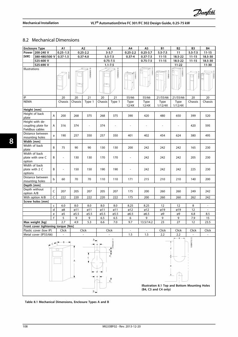
8.2 Mechanical Dimensions
Enclosure Type A1 A2 A3 A4 A5 B1 B2 B3 B4Power[kW]
200-240 V 0.25–1.5 0.25-2.2 3-3.7 0.25-2.2 0.25-3.7 5.5-7.5 11 5.5-7.5 11-15380-480/500 V 0.37-1.5 0.37-4.0 5.5-7.5 0.37-4 0.37-7.5 11-15 18.5-22 11-15 18.5-30525-600 V 0.75-7.5 0.75-7.5 11-15 18.5-22 11-15 18.5-30525-690 V 1.1-7.5 11-22 11-30
Illustrations13
0BA87
0.10
130B
A80
9.10
130B
A81
0.10
130B
B458
.10
130B
A81
1.10
130B
A81
2.10
130B
A81
3.10
130B
A82
6.10
130B
A82
7.10
IP 20 20 21 20 21 55/66 55/66 21/55/66 21/55/66 20 20NEMA Chassis Chassis Type 1 Chassis Type 1 Type
12/4XType12/4X
Type1/12/4X
Type1/12/4X
Chassis Chassis
Height [mm]Height of backplate A 200 268 375 268 375 390 420 480 650 399 520
Height with de-coupling plate forFieldbus cables
A 316 374 - 374 - - - - - 420 595
Distance betweenmounting holes a 190 257 350 257 350 401 402 454 624 380 495
Width [mm]Width of backplate B 75 90 90 130 130 200 242 242 242 165 230
Width of backplate with one Coption
B - 130 130 170 170 - 242 242 242 205 230
Width of backplate with 2 Coptions
B - 150 150 190 190 - 242 242 242 225 230
Distance betweenmounting holes b 60 70 70 110 110 171 215 210 210 140 200
Depth [mm]Depth withoutoption A/B C 207 205 207 205 207 175 200 260 260 249 242
With option A/B C 222 220 222 220 222 175 200 260 260 262 242Screw holes [mm]
c 6.0 8.0 8.0 8.0 8.0 8.25 8.25 12 12 8 -d ø8 ø11 ø11 ø11 ø11 ø12 ø12 ø19 ø19 12 -e ø5 ø5.5 ø5.5 ø5.5 ø5.5 ø6.5 ø6.5 ø9 ø9 6.8 8.5f 5 9 9 6.5 6.5 6 9 9 9 7.9 15
Max weight [kg] 2.7 4.9 5.3 6.6 7.0 9.7 13.5/14.2 23 27 12 23.5Front cover tightening torque [Nm]Plastic cover (low IP) Click Click Click - - Click Click Click ClickMetal cover (IP55/66) - - - 1.5 1.5 2.2 2.2 - -
C
a
b
130B
A64
8.12
f
e
B
A
a
d
e
b
c
a
e
f
130B
A71
5.12
Illustration 8.1 Top and Bottom Mounting Holes(B4, C3 and C4 only)
Table 8.1 Mechanical Dimensions, Enclosure Types A and B
Mechanical Installation VLT® AutomationDrive FC 301/FC 302 Design Guide, 0.25-75 kW
108 MG33BF02 - Rev. 2013-12-20
88

Enclosure Type C1 C2 C3 C4 D3hPower[kW]
200-240 V 15-22 30-37 18.5-22 30-37 -380-480/500 V 30-45 55-75 37-45 55-75 -525-600 V 30-45 55-90 37-45 55-90 -525-690 V 30-75 37-45 55-75
Illustrations
130B
A81
4.10
130B
A81
5.10
130B
A82
8.10
130B
A82
9.10
130B
C512
.10
IP 21/55/66 21/55/66 20 20 20NEMA Type 1/12/4X Type 1/12/4X Chassis Chassis ChassisHeight [mm]Height of back plate A 680 770 550 660 909Height with de-coupling plate forFieldbus cables A - - 630 800 -
Distance between mounting holes a 648 739 521 631 -Width [mm]Width of back plate B 308 370 308 370 250Width of back plate with one Coption B 308 370 308 370 -
Width of back plate with 2 Coptions B 308 370 308 370 -
Distance between mounting holes b 272 334 270 330 -Depth [mm]Depth without option A/B C 310 335 333 333 275With option A/B C 310 335 333 333 275Screw holes [mm]
c 12.5 12.5 - - -d ø19 ø19 - - -e ø9 ø9 8.5 8.5 -f 9.8 9.8 17 17 -
Max weight [kg] 45 65 35 50 62Front cover tightening torque [Nm]Plastic cover (low IP) Click Click 2.0 2.0 -Metal cover (IP55/66) 2.2 2.2 2.0 2.0 -
C
a
b
130B
A64
8.12
f
e
B
A
a
d
e
b
c
a
e
f
130B
A71
5.12
Illustration 8.1 Top and Bottom Mounting Holes (B4, C3and C4 only)
Table 8.2 Mechanical Dimensions, Enclosure Types C and D
NOTICEAccessory bags containing necessary brackets, screws and connectors are shipped with the frequency converters upondelivery.
Mechanical Installation VLT® AutomationDrive FC 301/FC 302 Design Guide, 0.25-75 kW
MG33BF02 - Rev. 2013-12-20 109
8 8

8.2.1 Mechanical Mounting
8.2.1.1 Clearance
All enclosure types allow side-by-side installation exceptwhen an IP21/IP4X/TYPE 1 enclosure kit is used (seechapter 11 Options and Accessories).
Side-by-side mountingIP20 A and B enclosure types can be arranged side-by-sidewith no clearance required between them, but themounting order is important. Illustration 8.1 shows how tomount the frames correctly.
130B
D38
9.11
A2
B3 B3
A2
Illustration 8.1 Correct Side-by-side Mounting
If the IP21 enclosure kit is used on enclosure types A1, A2or A3, there must be a clearance between the frequencyconverters of min. 50 mm.
For optimal cooling conditions, allow a free air passageabove and below the frequency converter. See Table 8.3.
a
b
130B
A41
9.10
Illustration 8.2 Clearance
Enclosure TypeA1*/A2/A3/A4/
A5/B1B2/B3/B4/
C1/C3C2/C4
a [mm] 100 200 225
b [mm] 100 200 225
Table 8.3 Air Passage for Different Enclosure Types
8.2.1.2 Wall Mounting
When mounting on a solid back wall the installation isstraight forward.
1. Drill holes in accordance with the measurementsgiven.
2. Provide screws suitable for the surface formounting the frequency converter. Retighten all 4screws.
If the frequency converter is to be mounted on a non-solidback wall, provide the frequency converter with a backplate, “1”, due to insufficient cooling air over the heat sink.
Mechanical Installation VLT® AutomationDrive FC 301/FC 302 Design Guide, 0.25-75 kW
110 MG33BF02 - Rev. 2013-12-20
88

NOTICEThe back plate is relevant for A4, A5, B1, B2, C1 and C2only.
130B
A21
9.11
1
1 Back plate
Illustration 8.3 Mounting on a non-solid Back-wall requires aBack Plate
For frequency converters with IP66 take extra care tomaintain the corrosive-resistant surface. A fibre washer or anylon washer may be used to protect the epoxy coating.
130B
A39
2.11
2
1
3
4
1 Back plate
2 IP66 frequency converter
3 Base plate
4 Fibre washer
Illustration 8.4 Mounting on a Non-solid Back Wall
Mechanical Installation VLT® AutomationDrive FC 301/FC 302 Design Guide, 0.25-75 kW
MG33BF02 - Rev. 2013-12-20 111
8 8
9 Electrical Installation
9.1 Safety
See chapter 2 Safety for general safety instructions.
WARNINGINDUCED VOLTAGEInduced voltage from output motor cables that runtogether can charge equipment capacitors even with theequipment turned off and locked out. Failure to runoutput motor cables separately or use screened cablescould result in death or serious injury.
• run output motor cables separately, or
• use screened cables
CAUTIONSHOCK HAZARDThe frequency converter can cause a DC current in thePE conductor.
• When a residual current-operated protectivedevice (RCD) is used for protection againstelectrical shock, only an RCD of Type B ispermitted on the supply side.
Failure to follow the recommendation means the RCDmay not provide the intended protection.
WARNINGLEAKAGE CURRENT HAZARDLeakage currents exceed 3.5 mA. Failure to ground thefrequency converter properly could result in death orserious injury.
• Ensure correct grounding of the equipment bya certified electrical installer.
For electrical safety
• Ground the frequency converter in accordancewith applicable standards and directives.
• Use a dedicated ground wire for input power,motor power and control wiring.
• Do not ground one frequency converter toanother in a “daisy chain” fashion.
• Keep the ground wire connections as short aspossible.
• Follow motor manufacturer wiring requirements.
• Minimum cable cross-section: 10 mm2 (or 2 ratedground wires terminated separately).
For EMC-compliant installation
• Establish electrical contact between cable screenand frequency converter enclosure by usingmetal cable glands or by using the clampsprovided on the equipment (seechapter 9.4 Motor Connection).
• Use high-strand wire to reduce electricalinterference.
• Do not use pigtails.
NOTICEPOTENTIAL EQUALISATIONRisk of electrical interference, when the ground potentialbetween the frequency converter and the system isdifferent. Install equalising cables between the systemcomponents. Recommended cable cross-section: 16 mm2.
Electrical Installation VLT® AutomationDrive FC 301/FC 302 Design Guide, 0.25-75 kW
112 MG33BF02 - Rev. 2013-12-20
99
WARNINGLEAKAGE CURRENT HAZARDLeakage currents exceed 3.5 mA. Failure to ground thefrequency converter properly could result in death orserious injury.
• Ensure correct grounding of the equipment bya certified electrical installer.
9.2 Cables
NOTICECables GeneralAll cabling must comply with national and localregulations on cable cross-sections and ambienttemperature. Copper (75 °C) conductors arerecommended.
Aluminium ConductorsTerminals can accept aluminium conductors, but theconductor surface has to be clean and the oxidation mustbe removed and sealed by neutral acid-free Vaselinegrease before the conductor is connected.Furthermore, the terminal screw must be retightened after2 days due to softness of the aluminium. It is crucial tokeep the connection a gas tight joint, otherwise thealuminium surface oxidises again.
9.2.1 Tightening Torque
EnclosureType
200-240 V[kW]
380-500 V[kW]
525-690 V[kW]
Cable for Tightening-up torque[Nm]
A1 0.25-1.5 0.37-1.5 -
Mains, Brake resistor, load sharing, Motor cables 0.5-0.6A2 0.25-2.2 0.37-4 -A3 3-3.7 5.5-7.5 1.1-7.5A4 0.25-2.2 0.37-4A5 3-3.7 5.5-7.5 -
B1 5.5-7.5 11-15 -Mains, Brake resistor, load sharing, Motor cables 1.8Relay 0.5-0.6Ground 2-3
B2 11 18.5-22 11-22
Mains, Brake resistor, load sharing cables 4.5Motor cables 4.5Relay 0.5-0.6Ground 2-3
B3 5.5-7.5 11-15 -Mains, Brake resistor, load sharing, Motor cables 1.8Relay 0.5-0.6Ground 2-3
B4 11-15 18.5-30 11-30Mains, Brake resistor, load sharing, Motor cables 4.5Relay 0.5-0.6Ground 2-3
C1 15-22 30-45 -
Mains, Brake resistor, load sharing cables 10Motor cables 10Relay 0.5-0.6Ground 2-3
C2 30-37 55-75 30-75
Mains, motor cables 14 (up to 9 5mm2)24 (over 95 mm2)
Load Sharing, brake cables 14Relay 0.5-0.6Ground 2-3
C3 18.5-22 30-37 37-45Mains, Brake resistor, load sharing, Motor cables 10Relay 0.5-0.6Ground 2-3
C4 37-45 55-75 -
Mains, motor cables 14 (up to 95 mm2)24 (over 95 mm2)
Load Sharing, brake cables 14Relay 0.5-0.6Ground 2-3
Table 9.1 Tightening Torque for Cables
Electrical Installation VLT® AutomationDrive FC 301/FC 302 Design Guide, 0.25-75 kW
MG33BF02 - Rev. 2013-12-20 113
9 9
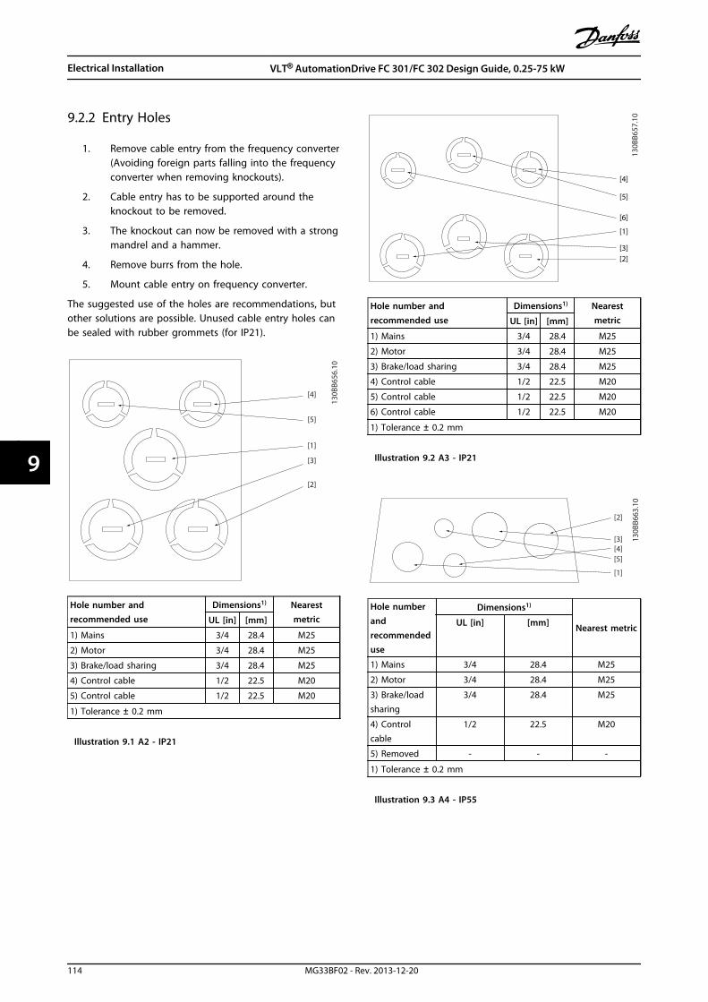
9.2.2 Entry Holes
1. Remove cable entry from the frequency converter(Avoiding foreign parts falling into the frequencyconverter when removing knockouts).
2. Cable entry has to be supported around theknockout to be removed.
3. The knockout can now be removed with a strongmandrel and a hammer.
4. Remove burrs from the hole.
5. Mount cable entry on frequency converter.
The suggested use of the holes are recommendations, butother solutions are possible. Unused cable entry holes canbe sealed with rubber grommets (for IP21).
[4]
[5]
[1]
[3]
[2]
130B
B656
.10
Hole number andrecommended use
Dimensions1) NearestmetricUL [in] [mm]
1) Mains 3/4 28.4 M25
2) Motor 3/4 28.4 M25
3) Brake/load sharing 3/4 28.4 M25
4) Control cable 1/2 22.5 M20
5) Control cable 1/2 22.5 M20
1) Tolerance ± 0.2 mm
Illustration 9.1 A2 - IP21
[4]
[5]
[6]
[1]
[3][2]
130B
B657
.10
Hole number andrecommended use
Dimensions1) NearestmetricUL [in] [mm]
1) Mains 3/4 28.4 M25
2) Motor 3/4 28.4 M25
3) Brake/load sharing 3/4 28.4 M25
4) Control cable 1/2 22.5 M20
5) Control cable 1/2 22.5 M20
6) Control cable 1/2 22.5 M20
1) Tolerance ± 0.2 mm
Illustration 9.2 A3 - IP21
[5]
[3]
[2]
[4]
[1]
130B
B663
.10
Hole numberandrecommendeduse
Dimensions1)
Nearest metricUL [in] [mm]
1) Mains 3/4 28.4 M25
2) Motor 3/4 28.4 M25
3) Brake/loadsharing
3/4 28.4 M25
4) Controlcable
1/2 22.5 M20
5) Removed - - -
1) Tolerance ± 0.2 mm
Illustration 9.3 A4 - IP55
Electrical Installation VLT® AutomationDrive FC 301/FC 302 Design Guide, 0.25-75 kW
114 MG33BF02 - Rev. 2013-12-20
99

[4]
[2]
[3]
[5][1]
130B
B665
.10
Hole number and recommended use Nearest metric
1) Mains M25
2) Motor M25
3) Brake/load sharing M25
4) Control cable M16
5) Control cable M20
Illustration 9.4 A4 - IP55 Threaded Gland Holes
[3]
[4]
[5]
[6]
[2]
[1]
130B
B664
.10
Hole numberandrecommendeduse
Dimensions1)
Nearest metricUL [in] [mm]
1) Mains 3/4 28.4 M25
2) Motor 3/4 28.4 M25
3) Brake/loadsharing
3/4 28.4 M25
4) Controlcable
3/4 28.4 M25
5) Control
cable2)
3/4 28.4 M25
6) Control
cable 2)
3/4 28.4 M25
1) Tolerance ± 0.2 mm2) Knock-out hole
Illustration 9.5 A5 - IP55
[4]
[5]
[3]
[6]
[2]
[1]
130B
B666
.10
Hole number and recommended use Nearest metric
1) Mains M25
2) Motor M25
3) Brake/load sharing 28.4 mm1)
4) Control cable M25
5) Control cable M25
6) Control cable M25
1) Knock-out hole
Illustration 9.6 A5- IP55 Threaded Gland Holes
[1]
[4]
[5]
[3]
[2]
130B
B659
.10
Hole numberandrecommendeduse
Dimensions1)
Nearest metricUL [in] [mm]
1) Mains 1 34.7 M32
2) Motor 1 34.7 M32
3) Brake/loadsharing
1 34.7 M32
4) Controlcable
1 34.7 M32
5) Controlcable
1/2 22.5 M20
1) Tolerance ± 0.2 mm
Illustration 9.7 B1 - IP21
Electrical Installation VLT® AutomationDrive FC 301/FC 302 Design Guide, 0.25-75 kW
MG33BF02 - Rev. 2013-12-20 115
9 9

[5]
[4]
[3]
[6]
[2]
[1]
130B
B667
.10
Hole numberandrecommendeduse
Dimensions1)
Nearest metricUL [in] [mm]
1) Mains 1 34.7 M32
2) Motor 1 34.7 M32
3) Brake/loadsharing
1 34.7 M32
4) Controlcable
3/4 28.4 M25
5) Controlcable
1/2 22.5 M20
5) Control
cable2)
1/2 22.5 M20
1) Tolerance ± 0.2 mm2) Knock-out hole
Illustration 9.8 B1 - IP55
[6]
[5]
[3]
[2]
[4]
[1]
130B
B669
.10
Hole number and recommended use Nearest metric
1) Mains M32
2) Motor M32
3) Brake/load sharing M32
4) Control cable M25
5) Control cable M25
6) Control cable 22.5 mm 1)
1) Knock-out hole
Illustration 9.9 B1 - IP55 Threaded Gland Holes
[1]
[4]
[5][3]
[2]
130B
B660
.10
Hole numberandrecommendeduse
Dimensions1)
Nearest metricUL [in] [mm]
1) Mains 1 1/4 44.2 M40
2) Motor 1 1/4 44.2 M40
3) Brake/loadsharing
1 34.7 M32
4) Controlcable
3/4 28.4 M25
5) Controlcable
1/2 22.5 M20
1) Tolerance ± 0.2 mm
Illustration 9.10 B2 - IP21
[4]
[3]
[5]
[2]
[1]
130B
B668
.10
Hole numberandrecommendeduse
Dimensions1)
Nearest metricUL [in] [mm]
1) Mains 1 1/4 44.2 M40
2) Motor 1 1/4 44.2 M40
3) Brake/loadsharing
1 34.7 M32
4) Controlcable
3/4 28.4 M25
5) Control
cable2)
1/2 22.5 M20
1) Tolerance ± 0.2 mm2) Knock-out hole
Illustration 9.11 B2 - IP55
Electrical Installation VLT® AutomationDrive FC 301/FC 302 Design Guide, 0.25-75 kW
116 MG33BF02 - Rev. 2013-12-20
99

[4]
[3]
[2]
[5]
[1]
130B
B670
.10
Hole number and recommended use Nearest metric
1) Mains M40
2) Motor M40
3) Brake/load sharing M32
4) Control cable M25
5) Control cable M20
Illustration 9.12 B2 - IP55 Threaded Gland Holes
[3]
[2]
[4][1]
[5]
[6]
130B
B658
.10
Hole numberandrecommendeduse
Dimensions1)
Nearest metricUL [in] [mm]
1) Mains 1 34.7 M32
2) Motor 1 34.7 M32
3) Brake/loadsharing
1 34.7 M32
4) Controlcable
1/2 22.5 M20
5) Controlcable
1/2 22.5 M20
6) Controlcable
1/2 22.5 M20
1) Tolerance ± 0.2 mm
Illustration 9.13 B3 - IP21
[5]
[3][2]
[4]
[1]
130B
B661
.10
Hole numberandrecommendeduse
Dimensions1)
Nearest metricUL [in] [mm]
1) Mains 2 63.3 M63
2) Motor 2 63.3 M63
3) Brake/loadsharing
1 1/2 50.2 M50
4) Controlcable
3/4 28.4 M25
5) Controlcable
1/2 22.5 M20
1) Tolerance ± 0.2 mm
Illustration 9.14 C1 - IP21
[5]
[3][2]
[6]
[4][1]
130B
B662
.10
Hole numberandrecommendeduse
Dimensions1)
Nearest metricUL [in] [mm]
1) Mains 2 63.3 M63
2) Motor 2 63.3 M63
3) Brake/loadsharing
1 1/2 50.2 M50
4) Controlcable
3/4 28.4 M25
5) Controlcable
1/2 22.5 M20
6) Controlcable
1/2 22.5 M20
1) Tolerance ±0.2 mm
Illustration 9.15 C2 - IP21
Electrical Installation VLT® AutomationDrive FC 301/FC 302 Design Guide, 0.25-75 kW
MG33BF02 - Rev. 2013-12-20 117
9 9

9.2.3 Tightening of the Cover afterConnections are Made
EnclosureType IP20 IP21 IP55 IP66
A1 * - - -
A2 * * - -
A3 * * - -
A4/A5 - - 2 2
B1 - * 2.2 2.2
B2 - * 2.2 2.2
B3 * - - -
B4 * - - -
C1 - * 2.2 2.2
C2 - * 2.2 2.2
C3 2 - - -
C4 2 - - -
* = No screws to tighten- = Does not exist
Table 9.2 Tightening of the Cover (Nm)
9.3 Mains Connection
It is mandatory to ground the mains connection properlyusing terminal 95 of the frequency converter, seechapter 9.1.1 Grounding.
The ground connection cable cross section must be atleast 10 mm2 or 2 x rated mains wires terminatedseparately according to EN 50178.Use unscreened cable.
3 Phase
power
input
130B
A02
6.10
91 (L1)
92 (L2)
93 (L3)
95 PE
Illustration 9.16 Mains Connection
NOTICEUsing fuses and/or circuit breakers on the supply side ismandatory to ensure compliance with IEC 60364 for CEor NEC 2009 for UL, see chapter 9.3.1.4 UL Compliance.
NOTICEExceeding 480 V RMSRISK OF DAMAGE TO THE FREQUENCYCONVERTER WITH RFI FILTER INSTALLEDWhen installed on a delta-grounded grid or an IT grid(including ground fault condition), mains input voltagein the range of 380-500 V (T4,T5) must not exceed 480 VRMS between mains and ground.
For some enclosures, the mounting is different if thefrequency converter is configured from factory with amains switch. The various scenarios are illustrated in thefollowing.
Mains connection for enclosures A1, A2 and A3:
NOTICEThe power plug connector can be used on frequencyconverters up to 7.5 kW.
1. Fit the 2 screws in the de-coupling plate, slide itinto place and tighten the screws.
2. Make sure the frequency converter is properlygrounded. Connect to ground connection(terminal 95). Use screw from the accessory bag.
3. Place plug connector 91 (L1), 92 (L2), 93 (L3) fromthe accessory bag onto the terminals labelledMAINS at the bottom of the frequency converter.
4. Attach mains wires to the mains plug connector.
5. Support the cable with the supporting enclosedbrackets.
Electrical Installation VLT® AutomationDrive FC 301/FC 302 Design Guide, 0.25-75 kW
118 MG33BF02 - Rev. 2013-12-20
99
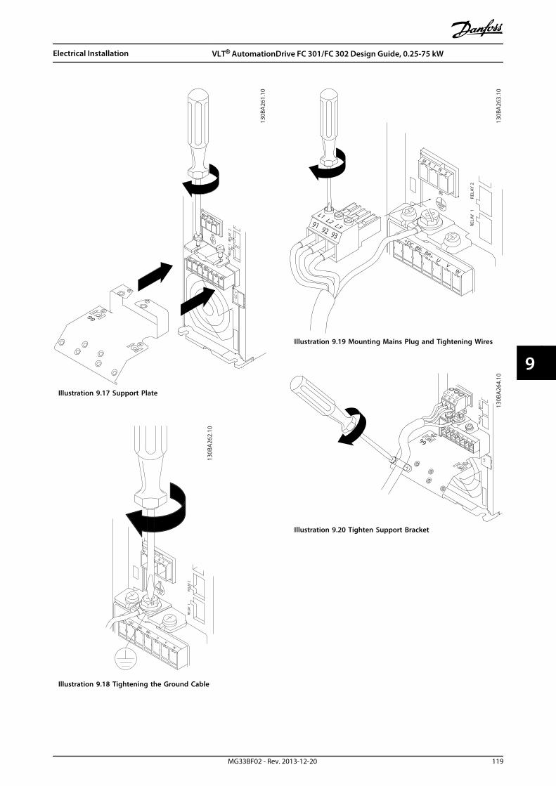
-DC+DC BR- BR+ U V W
99
M A I N S
95
RELA
Y 1
REL
AY 2
- LC
+
130B
A26
1.10
Illustration 9.17 Support Plate
130B
A26
2.10
M
I N S
+DCBR-
BR+U
V
W
RELA
Y 1
RELA
Y 295
Illustration 9.18 Tightening the Ground Cable
130B
A26
3.10
95
MA
I NS
+DC BR- BR+U
VW
91 92 93
L1L2 L3 RE
LAY
1
REL
AY 2
Illustration 9.19 Mounting Mains Plug and Tightening Wires
+DC BR- BR+U
VW
MA
I NS
L1 L2 L391 92 93
RELA
Y 1
R
ELAY
2
99
- LC
-
130B
A26
4.10
Illustration 9.20 Tighten Support Bracket
Electrical Installation VLT® AutomationDrive FC 301/FC 302 Design Guide, 0.25-75 kW
MG33BF02 - Rev. 2013-12-20 119
9 9

Mains connector enclosures A4/A5
L 1 L 2 L 3
91 92 93
130B
T336
.10
Illustration 9.21 Connecting to Mains and Grounding withoutDisconnector
130B
T335
.10
Illustration 9.22 Connecting to Mains and Grounding withDisconnector
When disconnector is used (enclosures A4/A5), mount thePE on the left side of the frequency converter.
130B
T332
.10
Illustration 9.23 Mains Connection Enclosures B1 and B2
130B
A72
5.10
Illustration 9.24 Mains Connection Enclosure B3
Electrical Installation VLT® AutomationDrive FC 301/FC 302 Design Guide, 0.25-75 kW
120 MG33BF02 - Rev. 2013-12-20
99
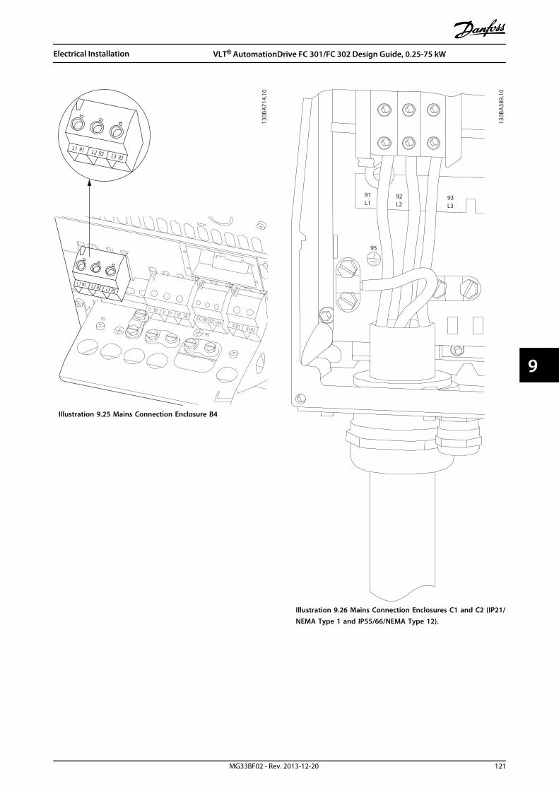
L1 91 L2 92 L3 93
L1 91 L2 92 L3 93
U 96 V 97 W 98 DC-88 DC+89 R-81 R+82
130B
A71
4.10
95
99
Illustration 9.25 Mains Connection Enclosure B4
130B
A38
9.10
95
91L1
92L2
93L3
Illustration 9.26 Mains Connection Enclosures C1 and C2 (IP21/NEMA Type 1 and IP55/66/NEMA Type 12).
Electrical Installation VLT® AutomationDrive FC 301/FC 302 Design Guide, 0.25-75 kW
MG33BF02 - Rev. 2013-12-20 121
9 9
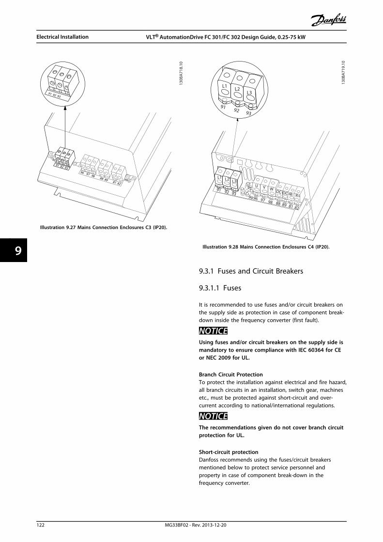
91 92 93
91 92 93
96 97 9888 89
81 82
99
95
130B
A71
8.10
Illustration 9.27 Mains Connection Enclosures C3 (IP20).
91
L1 L2 L3
92 93
91
L1 L2L3
92 93
99
95
96 97 98 88 89 81 82
U V W DC-DC+R- R+
130B
A71
9.10
Illustration 9.28 Mains Connection Enclosures C4 (IP20).
9.3.1 Fuses and Circuit Breakers
9.3.1.1 Fuses
It is recommended to use fuses and/or circuit breakers onthe supply side as protection in case of component break-down inside the frequency converter (first fault).
NOTICEUsing fuses and/or circuit breakers on the supply side ismandatory to ensure compliance with IEC 60364 for CEor NEC 2009 for UL.
Branch Circuit Protection To protect the installation against electrical and fire hazard,all branch circuits in an installation, switch gear, machinesetc., must be protected against short-circuit and over-current according to national/international regulations.
NOTICEThe recommendations given do not cover branch circuitprotection for UL.
Short-circuit protectionDanfoss recommends using the fuses/circuit breakersmentioned below to protect service personnel andproperty in case of component break-down in thefrequency converter.
Electrical Installation VLT® AutomationDrive FC 301/FC 302 Design Guide, 0.25-75 kW
122 MG33BF02 - Rev. 2013-12-20
99

9.3.1.2 Recommendations
The tables in chapter 9.3.1 Fuses and Circuit Breakers list therecommended rated current. Recommended fuses are ofthe type gG for small to medium power sizes. For largerpower sizes, aR fuses are recommended. For circuitbreakers, Moeller types are recommended. Other types ofcircuit breakers may be used, provided they limit theenergy into the frequency converter to a level equal to orlower than the Moeller types.
If fuses/circuit breakers according to recommendations areselected, possible damage on the frequency converter ismainly limited to damages inside the unit.
For further information see Application Note Fuses andCircuit Breakers, MN90T.
9.3.1.3 CE Compliance
Fuses or circuit breakers are mandatory to comply with IEC60364. Danfoss recommend using a selection of thefollowing.
The fuses below are suitable for use on a circuit capable ofdelivering 100,000 Arms (symmetrical), 240 V, 500 V, 600 V,or 690 V depending on the frequency converter voltagerating. With the proper fusing the frequency convertershort circuit current rating (SCCR) is 100,000 Arms.
The following UL listed fuses are suitable:
• UL248-4 class CC fuses
• UL248-8 class J fuses
• UL248-12 class R fuses (RK1)
• UL248-15 class T fuses
The following max. fuse size and type have been tested:
Enclosure Power [kW] Recommendedfuse size
Recommendedmax. fuse
Recommended circuitbreakerMoeller
Max trip level [A]
A1 0.25-1.5 gG-10 gG-25 PKZM0-10 10
A2 0.25-2.2 gG-10 (0.25-1.5)gG-16 (2.2)
gG-25 PKZM0-16 16
A3 3.0-3.7 gG-16 (3)gG-20 (3.7)
gG-32 PKZM0-25 25
A4 0.25-2.2 gG-10 (0.25-1.5)gG-16 (2.2)
gG-32 PKZM0-25 25
A5 0.25-3.7 gG-10 (0.25-1.5)gG-16 (2.2-3)gG-20 (3.7)
gG-32 PKZM0-25 25
B1 5.5-7.5 gG-25 (5.5)gG-32 (7.5)
gG-80 PKZM4-63 63
B2 11 gG-50 gG-100 NZMB1-A100 100
B3 5.5 gG-25 gG-63 PKZM4-50 50
B4 7.5-15 gG-32 (7.5)gG-50 (11)gG-63 (15)
gG-125 NZMB1-A100 100
C1 15-22 gG-63 (15)gG-80 (18.5)gG-100 (22)
gG-160 (15-18.5)aR-160 (22)
NZMB2-A200 160
C2 30-37 aR-160 (30)aR-200 (37)
aR-200 (30)aR-250 (37)
NZMB2-A250 250
C3 18.5-22 gG-80 (18.5)aR-125 (22)
gG-150 (18.5)aR-160 (22)
NZMB2-A200 150
C4 30-37 aR-160 (30)aR-200 (37)
aR-200 (30)aR-250 (37)
NZMB2-A250 250
Table 9.3 200-240 V, Enclosure Types A, B and C
Electrical Installation VLT® AutomationDrive FC 301/FC 302 Design Guide, 0.25-75 kW
MG33BF02 - Rev. 2013-12-20 123
9 9
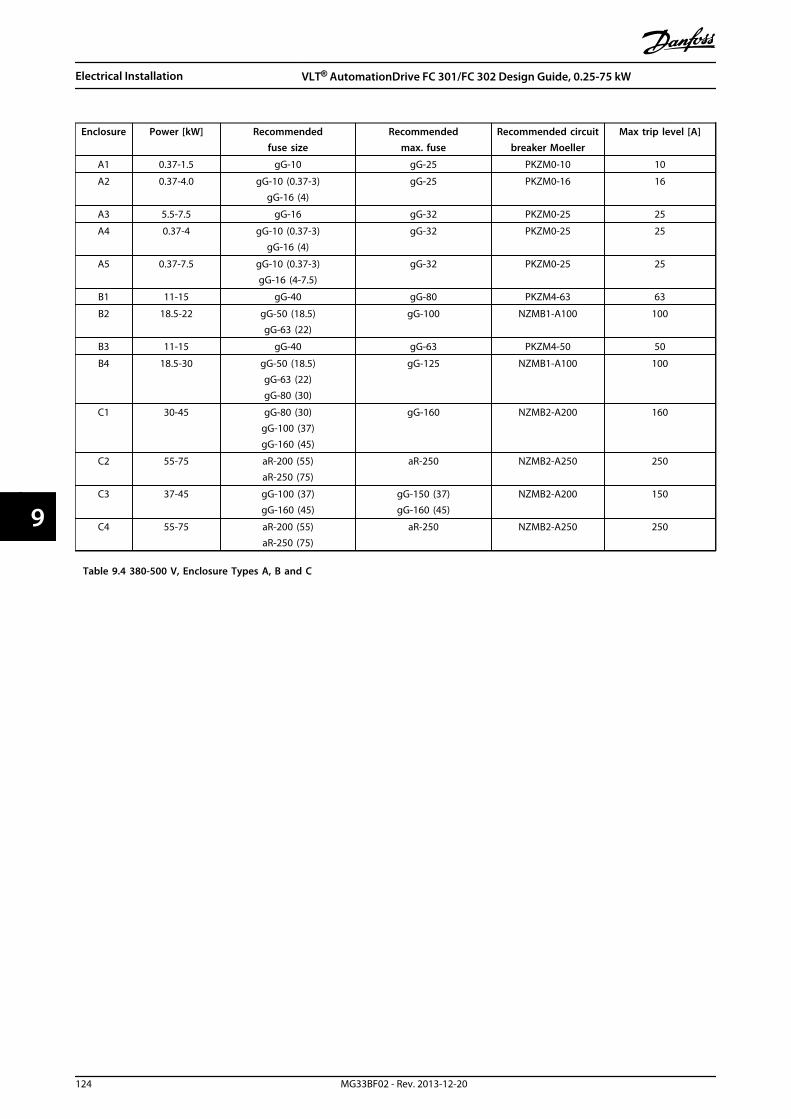
Enclosure Power [kW] Recommendedfuse size
Recommendedmax. fuse
Recommended circuitbreaker Moeller
Max trip level [A]
A1 0.37-1.5 gG-10 gG-25 PKZM0-10 10
A2 0.37-4.0 gG-10 (0.37-3)gG-16 (4)
gG-25 PKZM0-16 16
A3 5.5-7.5 gG-16 gG-32 PKZM0-25 25
A4 0.37-4 gG-10 (0.37-3)gG-16 (4)
gG-32 PKZM0-25 25
A5 0.37-7.5 gG-10 (0.37-3)gG-16 (4-7.5)
gG-32 PKZM0-25 25
B1 11-15 gG-40 gG-80 PKZM4-63 63
B2 18.5-22 gG-50 (18.5)gG-63 (22)
gG-100 NZMB1-A100 100
B3 11-15 gG-40 gG-63 PKZM4-50 50
B4 18.5-30 gG-50 (18.5)gG-63 (22)gG-80 (30)
gG-125 NZMB1-A100 100
C1 30-45 gG-80 (30)gG-100 (37)gG-160 (45)
gG-160 NZMB2-A200 160
C2 55-75 aR-200 (55)aR-250 (75)
aR-250 NZMB2-A250 250
C3 37-45 gG-100 (37)gG-160 (45)
gG-150 (37)gG-160 (45)
NZMB2-A200 150
C4 55-75 aR-200 (55)aR-250 (75)
aR-250 NZMB2-A250 250
Table 9.4 380-500 V, Enclosure Types A, B and C
Electrical Installation VLT® AutomationDrive FC 301/FC 302 Design Guide, 0.25-75 kW
124 MG33BF02 - Rev. 2013-12-20
99

Enclosure Power [kW] Recommendedfuse size
Recommendedmax. fuse
Recommended circuitbreakerMoeller
Max trip level [A]
A2 0-75-4.0 gG-10 gG-25 PKZM0-16 16
A3 5.5-7.5 gG-10 (5.5)gG-16 (7.5)
gG-32 PKZM0-25 25
A5 0.75-7.5 gG-10 (0.75-5.5)gG-16 (7.5)
gG-32 PKZM0-25 25
B1 11-18 gG-25 (11)gG-32 (15)
gG-40 (18.5)
gG-80 PKZM4-63 63
B2 22-30 gG-50 (22)gG-63 (30)
gG-100 NZMB1-A100 100
B3 11-15 gG-25 (11)gG-32 (15)
gG-63 PKZM4-50 50
B4 18.5-30 gG-40 (18.5)gG-50 (22)gG-63 (30)
gG-125 NZMB1-A100 100
C1 37-55 gG-63 (37)gG-100 (45)aR-160 (55)
gG-160 (37-45)aR-250 (55)
NZMB2-A200 160
C2 75 aR-200 (75) aR-250 NZMB2-A250 250
C3 37-45 gG-63 (37)gG-100 (45)
gG-150 NZMB2-A200 150
C4 55-75 aR-160 (55)aR-200 (75)
aR-250 NZMB2-A250 250
Table 9.5 525-600 V, Enclosure Types A, B and C
Enclosure Power [kW] Recommendedfuse size
Recommendedmax. fuse
Recommended circuitbreakerMoeller
Max trip level [A]
A3 1.11.52.234
5.57.5
gG-6gG-6gG-6
gG-10gG-10gG-16gG-16
gG-25gG-25gG-25gG-25gG-25gG-25gG-25
PKZM0-16 16
B2/B4 11151822
gG-25 (11)gG-32 (15)gG-32 (18)gG-40 (22)
gG-63 - -
B4/C2 30 gG-63 (30) gG-80 (30) - -
C2/C3 3745
gG-63 (37)gG-80 (45)
gG-100 (37)gG-125 (45)
C2 5575
gG-100 (55)gG-125 (75)
gG-160 (55-75)
Table 9.6 525-690 V, Enclosure Types A, B and C
Electrical Installation VLT® AutomationDrive FC 301/FC 302 Design Guide, 0.25-75 kW
MG33BF02 - Rev. 2013-12-20 125
9 9

9.3.1.4 UL Compliance
The fuses below are suitable for use on a circuit capable of delivering 100,000 Arms (symmetrical), 240 V, or 500 V, or 600 Vdepending on the frequency converter voltage rating. With the proper fusing, the frequency converter Short Circuit CurrentRating (SCCR) is 100,000 Arms.
Fuses or circuit breakers are mandatory to comply with NEC 2009. Danfoss recommends using a selection of the following:
Recommended max. fuse
Power[kW]
Bussmann
Type RK1 1)
BussmannType J
BussmannType T
BussmannType CC
BussmannType CC
BussmannType CC
0.25-0.37 KTN-R-05 JKS-05 JJN-05 FNQ-R-5 KTK-R-5 LP-CC-5
0.55-1.1 KTN-R-10 JKS-10 JJN-10 FNQ-R-10 KTK-R-10 LP-CC-10
1.5 KTN-R-15 JKS-15 JJN-15 FNQ-R-15 KTK-R-15 LP-CC-15
2.2 KTN-R-20 JKS-20 JJN-20 FNQ-R-20 KTK-R-20 LP-CC-20
3.0 KTN-R-25 JKS-25 JJN-25 FNQ-R-25 KTK-R-25 LP-CC-25
3.7 KTN-R-30 JKS-30 JJN-30 FNQ-R-30 KTK-R-30 LP-CC-30
5.5 KTN-R-50 KS-50 JJN-50 - - -
7.5 KTN-R-60 JKS-60 JJN-60 - - -
11 KTN-R-80 JKS-80 JJN-80 - - -
15-18.5 KTN-R-125 JKS-125 JJN-125 - - -
22 KTN-R-150 JKS-150 JJN-150 - - -
30 KTN-R-200 JKS-200 JJN-200 - - -
37 KTN-R-250 JKS-250 JJN-250 - - -
Table 9.7 200-240 V, Enclosure Types A, B and C
Recommended max. fuse
Power[kW]
SIBAType RK1
Littel fuseType RK1
Ferraz-ShawmutType CC
Ferraz-Shawmut
Type RK13)
0.25-0.37 5017906-005 KLN-R-05 ATM-R-05 A2K-05-R
0.55-1.1 5017906-010 KLN-R-10 ATM-R-10 A2K-10-R
1.5 5017906-016 KLN-R-15 ATM-R-15 A2K-15-R
2.2 5017906-020 KLN-R-20 ATM-R-20 A2K-20-R
3.0 5017906-025 KLN-R-25 ATM-R-25 A2K-25-R
3.7 5012406-032 KLN-R-30 ATM-R-30 A2K-30-R
5.5 5014006-050 KLN-R-50 - A2K-50-R
7.5 5014006-063 KLN-R-60 - A2K-60-R
11 5014006-080 KLN-R-80 - A2K-80-R
15-18.5 2028220-125 KLN-R-125 - A2K-125-R
22 2028220-150 KLN-R-150 - A2K-150-R
30 2028220-200 KLN-R-200 - A2K-200-R
37 2028220-250 KLN-R-250 - A2K-250-R
Table 9.8 200-240 V, Enclosure Types A, B and C
Electrical Installation VLT® AutomationDrive FC 301/FC 302 Design Guide, 0.25-75 kW
126 MG33BF02 - Rev. 2013-12-20
99

Recommended max. fuse
Power[kW]
Bussmann
Type JFHR22)
Littel fuseJFHR2
Ferraz-Shawmut
JFHR24)
Ferraz-Shawmut
J
0.25-0.37 FWX-5 - - HSJ-6
0.55-1.1 FWX-10 - - HSJ-10
1.5 FWX-15 - - HSJ-15
2.2 FWX-20 - - HSJ-20
3.0 FWX-25 - - HSJ-25
3.7 FWX-30 - - HSJ-30
5.5 FWX-50 - - HSJ-50
7.5 FWX-60 - - HSJ-60
11 FWX-80 - - HSJ-80
15-18.5 FWX-125 - - HSJ-125
22 FWX-150 L25S-150 A25X-150 HSJ-150
30 FWX-200 L25S-200 A25X-200 HSJ-200
37 FWX-250 L25S-250 A25X-250 HSJ-250
Table 9.9 200-240 V, Enclosure Types A, B and C
1) KTS-fuses from Bussmann may substitute KTN for 240 V frequency converters.
2) FWH-fuses from Bussmann may substitute FWX for 240 V frequency converters.
3) A6KR fuses from FERRAZ SHAWMUT may substitute A2KR for 240 V frequency converters.
4) A50X fuses from FERRAZ SHAWMUT may substitute A25X for 240 V frequency converters.
Recommended max. fuse
Power[kW]
BussmannType RK1
BussmannType J
BussmannType T
BussmannType CC
BussmannType CC
BussmannType CC
0.37-1.1 KTS-R-6 JKS-6 JJS-6 FNQ-R-6 KTK-R-6 LP-CC-6
1.5-2.2 KTS-R-10 JKS-10 JJS-10 FNQ-R-10 KTK-R-10 LP-CC-10
3 KTS-R-15 JKS-15 JJS-15 FNQ-R-15 KTK-R-15 LP-CC-15
4 KTS-R-20 JKS-20 JJS-20 FNQ-R-20 KTK-R-20 LP-CC-20
5.5 KTS-R-25 JKS-25 JJS-25 FNQ-R-25 KTK-R-25 LP-CC-25
7.5 KTS-R-30 JKS-30 JJS-30 FNQ-R-30 KTK-R-30 LP-CC-30
11 KTS-R-40 JKS-40 JJS-40 - - -
15 KTS-R-50 JKS-50 JJS-50 - - -
18 KTS-R-60 JKS-60 JJS-60 - - -
22 KTS-R-80 JKS-80 JJS-80 - - -
30 KTS-R-100 JKS-100 JJS-100 - - -
37 KTS-R-125 JKS-125 JJS-125 - - -
45 KTS-R-150 JKS-150 JJS-150 - - -
55 KTS-R-200 JKS-200 JJS-200 - - -
75 KTS-R-250 JKS-250 JJS-250 - - -
Table 9.10 380-500 V, Enclosure Types A, B and C
Electrical Installation VLT® AutomationDrive FC 301/FC 302 Design Guide, 0.25-75 kW
MG33BF02 - Rev. 2013-12-20 127
9 9

Recommended max. fuse
Power[kW]
SIBAType RK1
Littel fuseType RK1
Ferraz-ShawmutType CC
Ferraz-ShawmutType RK1
0.37-1.1 5017906-006 KLS-R-6 ATM-R-6 A6K-6-R
1.5-2.2 5017906-010 KLS-R-10 ATM-R-10 A6K-10-R
3 5017906-016 KLS-R-15 ATM-R-15 A6K-15-R
4 5017906-020 KLS-R-20 ATM-R-20 A6K-20-R
5.5 5017906-025 KLS-R-25 ATM-R-25 A6K-25-R
7.5 5012406-032 KLS-R-30 ATM-R-30 A6K-30-R
11 5014006-040 KLS-R-40 - A6K-40-R
15 5014006-050 KLS-R-50 - A6K-50-R
18 5014006-063 KLS-R-60 - A6K-60-R
22 2028220-100 KLS-R-80 - A6K-80-R
30 2028220-125 KLS-R-100 - A6K-100-R
37 2028220-125 KLS-R-125 - A6K-125-R
45 2028220-160 KLS-R-150 - A6K-150-R
55 2028220-200 KLS-R-200 - A6K-200-R
75 2028220-250 KLS-R-250 - A6K-250-R
Table 9.11 380-500 V, Enclosure Types A, B and C
Electrical Installation VLT® AutomationDrive FC 301/FC 302 Design Guide, 0.25-75 kW
128 MG33BF02 - Rev. 2013-12-20
99
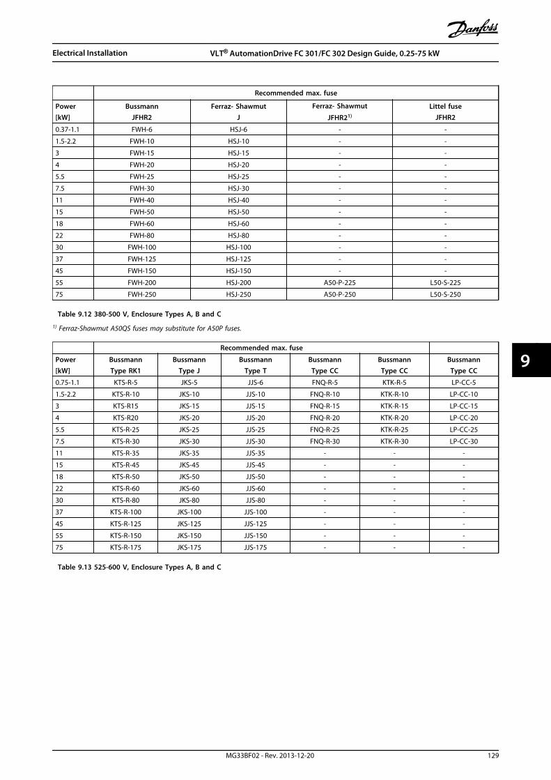
Recommended max. fuse
Power[kW]
BussmannJFHR2
Ferraz- ShawmutJ
Ferraz- Shawmut
JFHR21)
Littel fuseJFHR2
0.37-1.1 FWH-6 HSJ-6 - -
1.5-2.2 FWH-10 HSJ-10 - -
3 FWH-15 HSJ-15 - -
4 FWH-20 HSJ-20 - -
5.5 FWH-25 HSJ-25 - -
7.5 FWH-30 HSJ-30 - -
11 FWH-40 HSJ-40 - -
15 FWH-50 HSJ-50 - -
18 FWH-60 HSJ-60 - -
22 FWH-80 HSJ-80 - -
30 FWH-100 HSJ-100 - -
37 FWH-125 HSJ-125 - -
45 FWH-150 HSJ-150 - -
55 FWH-200 HSJ-200 A50-P-225 L50-S-225
75 FWH-250 HSJ-250 A50-P-250 L50-S-250
Table 9.12 380-500 V, Enclosure Types A, B and C
1) Ferraz-Shawmut A50QS fuses may substitute for A50P fuses.
Recommended max. fuse
Power[kW]
BussmannType RK1
BussmannType J
BussmannType T
BussmannType CC
BussmannType CC
BussmannType CC
0.75-1.1 KTS-R-5 JKS-5 JJS-6 FNQ-R-5 KTK-R-5 LP-CC-5
1.5-2.2 KTS-R-10 JKS-10 JJS-10 FNQ-R-10 KTK-R-10 LP-CC-10
3 KTS-R15 JKS-15 JJS-15 FNQ-R-15 KTK-R-15 LP-CC-15
4 KTS-R20 JKS-20 JJS-20 FNQ-R-20 KTK-R-20 LP-CC-20
5.5 KTS-R-25 JKS-25 JJS-25 FNQ-R-25 KTK-R-25 LP-CC-25
7.5 KTS-R-30 JKS-30 JJS-30 FNQ-R-30 KTK-R-30 LP-CC-30
11 KTS-R-35 JKS-35 JJS-35 - - -
15 KTS-R-45 JKS-45 JJS-45 - - -
18 KTS-R-50 JKS-50 JJS-50 - - -
22 KTS-R-60 JKS-60 JJS-60 - - -
30 KTS-R-80 JKS-80 JJS-80 - - -
37 KTS-R-100 JKS-100 JJS-100 - - -
45 KTS-R-125 JKS-125 JJS-125 - - -
55 KTS-R-150 JKS-150 JJS-150 - - -
75 KTS-R-175 JKS-175 JJS-175 - - -
Table 9.13 525-600 V, Enclosure Types A, B and C
Electrical Installation VLT® AutomationDrive FC 301/FC 302 Design Guide, 0.25-75 kW
MG33BF02 - Rev. 2013-12-20 129
9 9

Recommended max. fuse
Power [kW]SIBA
Type RK1Littel fuseType RK1
Ferraz-ShawmutType RK1
Ferraz-Shawmut
J
0.75-1.1 5017906-005 KLS-R-005 A6K-5-R HSJ-6
1.5-2.2 5017906-010 KLS-R-010 A6K-10-R HSJ-10
3 5017906-016 KLS-R-015 A6K-15-R HSJ-15
4 5017906-020 KLS-R-020 A6K-20-R HSJ-20
5.5 5017906-025 KLS-R-025 A6K-25-R HSJ-25
7.5 5017906-030 KLS-R-030 A6K-30-R HSJ-30
11 5014006-040 KLS-R-035 A6K-35-R HSJ-35
15 5014006-050 KLS-R-045 A6K-45-R HSJ-45
18 5014006-050 KLS-R-050 A6K-50-R HSJ-50
22 5014006-063 KLS-R-060 A6K-60-R HSJ-60
30 5014006-080 KLS-R-075 A6K-80-R HSJ-80
37 5014006-100 KLS-R-100 A6K-100-R HSJ-100
45 2028220-125 KLS-R-125 A6K-125-R HSJ-125
55 2028220-150 KLS-R-150 A6K-150-R HSJ-150
75 2028220-200 KLS-R-175 A6K-175-R HSJ-175
Table 9.14 525-600 V, Enclosure Types A, B and C
Recommended max. fuse
Power[kW]
BussmannType RK1
BussmannType J
BussmannType T
BussmannType CC
BussmannType CC
BussmannType CC
[kW]
1.1 KTS-R-5 JKS-5 JJS-6 FNQ-R-5 KTK-R-5 LP-CC-5
1.5-2.2 KTS-R-10 JKS-10 JJS-10 FNQ-R-10 KTK-R-10 LP-CC-10
3 KTS-R15 JKS-15 JJS-15 FNQ-R-15 KTK-R-15 LP-CC-15
4 KTS-R20 JKS-20 JJS-20 FNQ-R-20 KTK-R-20 LP-CC-20
5.5 KTS-R-25 JKS-25 JJS-25 FNQ-R-25 KTK-R-25 LP-CC-25
7.5 KTS-R-30 JKS-30 JJS-30 FNQ-R-30 KTK-R-30 LP-CC-30
11 KTS-R-35 JKS-35 JJS-35 - - -
15 KTS-R-45 JKS-45 JJS-45 - - -
18 KTS-R-50 JKS-50 JJS-50 - - -
22 KTS-R-60 JKS-60 JJS-60 - - -
30 KTS-R-80 JKS-80 JJS-80 - - -
37 KTS-R-100 JKS-100 JJS-100 - - -
45 KTS-R-125 JKS-125 JJS-125 - - -
55 KTS-R-150 JKS-150 JJS-150 - - -
75 KTS-R-175 JKS-175 JJS-175 - - -
Table 9.15 525-690 V, Enclosure Types A, B and C
Electrical Installation VLT® AutomationDrive FC 301/FC 302 Design Guide, 0.25-75 kW
130 MG33BF02 - Rev. 2013-12-20
99

Recommended max. fuse
Power[kW]
Max.prefuse
BussmannE52273
RK1/JDDZ
BussmannE4273J/JDDZ
BussmannE4273
T/JDDZ
SIBAE180276
RK1/JDDZ
LittelFuseE81895
RK1/JDDZ
Ferraz-Shawmut
E163267/E2137RK1/JDDZ
Ferraz-Shawmut
E2137J/HSJ
11 30 A KTS-R-30 JKS-30 JKJS-30 5017906-030 KLS-R-030 A6K-30-R HST-30
15-18.5 45 A KTS-R-45 JKS-45 JJS-45 5014006-050 KLS-R-045 A6K-45-R HST-45
22 60 A KTS-R-60 JKS-60 JJS-60 5014006-063 KLS-R-060 A6K-60-R HST-60
30 80 A KTS-R-80 JKS-80 JJS-80 5014006-080 KLS-R-075 A6K-80-R HST-80
37 90 A KTS-R-90 JKS-90 JJS-90 5014006-100 KLS-R-090 A6K-90-R HST-90
45 100 A KTS-R-100 JKS-100 JJS-100 5014006-100 KLS-R-100 A6K-100-R HST-100
55 125 A KTS-R-125 JKS-125 JJS-125 2028220-125 KLS-150 A6K-125-R HST-125
75 150 A KTS-R-150 JKS-150 JJS-150 2028220-150 KLS-175 A6K-150-R HST-150
Table 9.16 525-690 V,Enclosure Types B and C
Electrical Installation VLT® AutomationDrive FC 301/FC 302 Design Guide, 0.25-75 kW
MG33BF02 - Rev. 2013-12-20 131
9 9
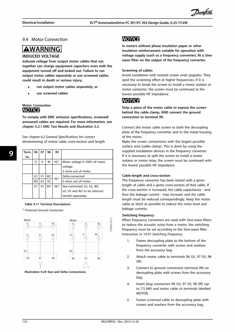
9.4 Motor Connection
WARNINGINDUCED VOLTAGEInduced voltage from output motor cables that runtogether can charge equipment capacitors even with theequipment turned off and locked out. Failure to runoutput motor cables separately or use screened cablescould result in death or serious injury.
• run output motor cables separately, or
• use screened cables
Motor Connection
NOTICETo comply with EMC emission specifications, screened/armoured cables are required. For more information, seechapter 5.2.1 EMC Test Results and Illustration 3.3.
See chapter 6.2 General Specifications for correctdimensioning of motor cable cross-section and length.
Term.no.
96 97 98 99
U V W PE1) Motor voltage 0-100% of mainsvoltage.3 wires out of motor
U1 V1 W1PE1)
Delta-connected
W2 U2 V2 6 wires out of motor
U1 V1 W1 PE1) Star-connected U2, V2, W2U2, V2 and W2 to be intercon-nected separately.
Table 9.17 Terminal Descriptions
1) Protected Ground Connection
U1
V1
W1
175Z
A11
4.11
96 97 98 96 97 98
FC FC
Motor MotorU
2V2
W2
U1
V1
W1
U2
V2
W2
Illustration 9.29 Star and Delta Connections
NOTICEIn motors without phase insulation paper or otherinsulation reinforcement suitable for operation withvoltage supply (such as a frequency converter), fit a Sine-wave filter on the output of the frequency converter.
Screening of cablesAvoid installation with twisted screen ends (pigtails). Theyspoil the screening effect at higher frequencies. If it isnecessary to break the screen to install a motor isolator ormotor contactor, the screen must be continued at thelowest possible HF impedance.
NOTICEStrip a piece of the motor cable to expose the screenbehind the cable clamp, AND connect the groundconnection to terminal 99.
Connect the motor cable screen to both the decouplingplate of the frequency converter and to the metal housingof the motor.Make the screen connections with the largest possiblesurface area (cable clamp). This is done by using thesupplied installation devices in the frequency converter.If it is necessary to split the screen to install a motorisolator or motor relay, the screen must be continued withthe lowest possible HF impedance.
Cable-length and cross-sectionThe frequency converter has been tested with a givenlength of cable and a given cross-section of that cable. Ifthe cross-section is increased, the cable capacitance - andthus the leakage current - may increase, and the cablelength must be reduced correspondingly. Keep the motorcable as short as possible to reduce the noise level andleakage currents.
Switching frequencyWhen frequency converters are used with Sine-wave filtersto reduce the acoustic noise from a motor, the switchingfrequency must be set according to the Sine-wave filterinstruction in 14-01 Switching Frequency.
1. Fasten decoupling plate to the bottom of thefrequency converter with screws and washersfrom the accessory bag.
2. Attach motor cable to terminals 96 (U), 97 (V), 98(W).
3. Connect to ground connection (terminal 99) ondecoupling plate with screws from the accessorybag.
4. Insert plug connectors 96 (U), 97 (V), 98 (W) (upto 7.5 kW) and motor cable to terminals labelledMOTOR.
5. Fasten screened cable to decoupling plate withscrews and washers from the accessory bag.
Electrical Installation VLT® AutomationDrive FC 301/FC 302 Design Guide, 0.25-75 kW
132 MG33BF02 - Rev. 2013-12-20
99

All types of 3-phase asynchronous standard motors can beconnected to the frequency converter. Normally, smallmotors are star-connected (230/400 V, Y). Large motors arenormally delta-connected (400/690 V, Δ). Refer to themotor name plate for correct connection mode andvoltage.
MOTOR
MOTORU V W
99
130B
T302
.12
Illustration 9.30 Motor Connection for Enclosures A1, A2 andA3
UV
W
9697
98
130B
T337
.10
Illustration 9.31 Motor Connection for Enclosures A4/A5
130B
T333
.10
Illustration 9.32 Motor Connection for Enclosures B1 and B2
Electrical Installation VLT® AutomationDrive FC 301/FC 302 Design Guide, 0.25-75 kW
MG33BF02 - Rev. 2013-12-20 133
9 9

130B
A72
6.10
Illustration 9.33 Motor Connection for Enclosure B3
U 96 V 97 W 98
U 96 V 97 W 98
L1 91 L2 92 L3 93
DC- 88 DC+89 R- 81 R+ 82
130B
A72
1.10
99
Illustration 9.34 Motor Connection for Enclosure B4
91L1
92L2
93L3
96U
97V
98W
88DC-
89DC+
81R-
8R+
130B
A39
0.11
9995
Illustration 9.35 Motor Connection Enclosures C1 and C2 (IP21/NEMA Type 1 and IP55/66/NEMA Type 12)
130B
A74
0.10
DC- DC+ R- R+
88 89 81 82
97
U V W
99 9698
L1
91
L2
92
L3
93
97
U V W
9698
Illustration 9.36 Motor Connection for Enclosures C3 and C4
9.5 Earth Leakage Current Protection
Follow national and local codes regarding protectiveearthing of equipment with a leakage current > 3,5 mA.The protective earth connection must have a cross sectionof minimum 10 mm2 or consist of 2 separate wires eachwith the same cross section as the phase wires. Frequencyconverter technology implies high frequency switching athigh power. This generates a leakage current in the earthconnection.
Electrical Installation VLT® AutomationDrive FC 301/FC 302 Design Guide, 0.25-75 kW
134 MG33BF02 - Rev. 2013-12-20
99

The earth leakage current is made up of several contri-butions and depends on various system configurationsincluding RFI filtering, motor cable length, motor cablescreening, and frequency converter power.
130B
B955
.12
a
b
Leakage current
Motor cable length
Illustration 9.37 Motor Cable Length and Power Size Influenceon Leakage Current. Powersize a > Powersize b
The leakage current also depends on the line distortion.
130B
B956
.12
THVD=0%
THVD=5%
Leakage current
Illustration 9.38 Line Distortion Influences Leakage Current
EN/IEC61800-5-1 (Power Drive System Product Standard)requires special care if the leakage current exceeds 3.5 mA.Grounding must be reinforced in one of the followingways:
• Ground wire (terminal 95) of at least 10 mm2
• 2 separate ground wires both complying with thedimensioning rules
See EN/IEC61800-5-1 and EN50178 for further information.
Using RCDsWhere residual current devices (RCDs), also known as earthleakage circuit breakers (ELCBs), are used, comply with thefollowing:
• Use RCDs of type B only as they are capable ofdetecting AC and DC currents
• Use RCDs with a delay to prevent faults due totransient earth currents
• Dimension RCDs according to the system configu-ration and environmental considerations
The leakage current includes several frequenciesoriginating from both the mains frequency and theswitching frequency. Whether the switching frequency isdetected depends on the type of RCD used.
130B
B958
.12
f sw
Cable
150 Hz
3rd harmonics
50 Hz
Mains
RCD with low f cut-
RCD with high fcut-
Leakage current
Frequency
Illustration 9.39 Main Contributions to Leakage Current
Electrical Installation VLT® AutomationDrive FC 301/FC 302 Design Guide, 0.25-75 kW
MG33BF02 - Rev. 2013-12-20 135
9 9
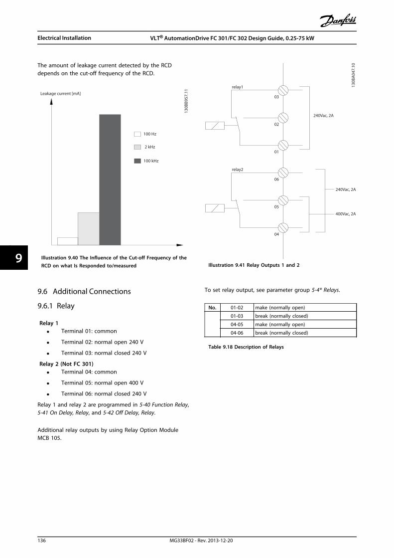
The amount of leakage current detected by the RCDdepends on the cut-off frequency of the RCD.
130B
B957
.11
Leakage current [mA]
100 Hz
2 kHz
100 kHz
Illustration 9.40 The Influence of the Cut-off Frequency of theRCD on what Is Responded to/measured
9.6 Additional Connections
9.6.1 Relay
Relay 1• Terminal 01: common
• Terminal 02: normal open 240 V
• Terminal 03: normal closed 240 V
Relay 2 (Not FC 301)• Terminal 04: common
• Terminal 05: normal open 400 V
• Terminal 06: normal closed 240 V
Relay 1 and relay 2 are programmed in 5-40 Function Relay,5-41 On Delay, Relay, and 5-42 Off Delay, Relay.
Additional relay outputs by using Relay Option ModuleMCB 105.
relay1
relay2
03
02
240Vac, 2A
240Vac, 2A
400Vac, 2A
01
06
05
04
130B
A04
7.10
Illustration 9.41 Relay Outputs 1 and 2
To set relay output, see parameter group 5-4* Relays.
No. 01-02 make (normally open)
01-03 break (normally closed)
04-05 make (normally open)
04-06 break (normally closed)
Table 9.18 Description of Relays
Electrical Installation VLT® AutomationDrive FC 301/FC 302 Design Guide, 0.25-75 kW
136 MG33BF02 - Rev. 2013-12-20
99

130B
A02
9.12
Relay2Relay1
35 36
Illustration 9.42 Terminals for Relay Connection(Enclosure Types A1, A2 and A3).
130B
A39
1.12
RE
LA
Y 1
RE
LA
Y 2
06
05
04
03
02
01
DC+
Illustration 9.43 Terminals for Relay Connection(Enclosure Types C1 and C2).
311
130B
A21
5.10
RELAY 1RELAY 2
9
9
6
03 02 01
90 05 04
Illustration 9.44 Terminals for Relay Connection(Enclosure Types A5, B1 and B2).
Electrical Installation VLT® AutomationDrive FC 301/FC 302 Design Guide, 0.25-75 kW
MG33BF02 - Rev. 2013-12-20 137
9 9
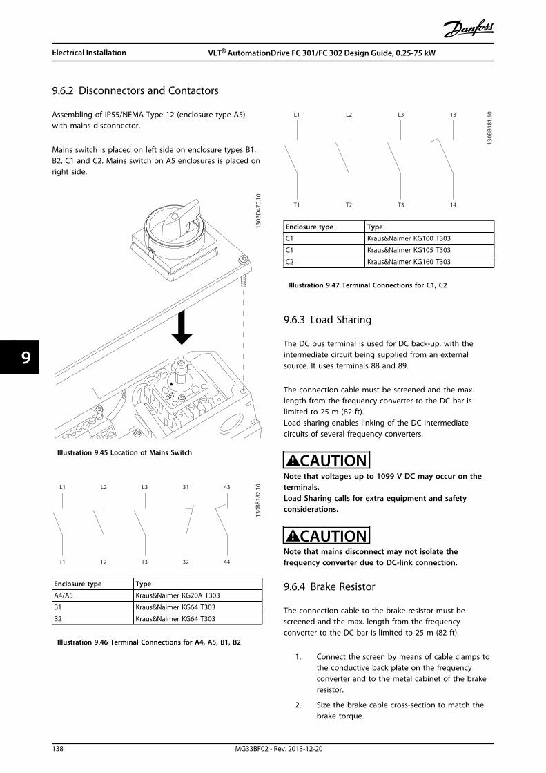
9.6.2 Disconnectors and Contactors
Assembling of IP55/NEMA Type 12 (enclosure type A5)with mains disconnector.
Mains switch is placed on left side on enclosure types B1,B2, C1 and C2. Mains switch on A5 enclosures is placed onright side.
130B
D47
0.10
OFF
Illustration 9.45 Location of Mains Switch
L1
T1
L2
T2
L3
T3
31
32
43
44
130B
B182
.10
Enclosure type Type
A4/A5 Kraus&Naimer KG20A T303
B1 Kraus&Naimer KG64 T303
B2 Kraus&Naimer KG64 T303
Illustration 9.46 Terminal Connections for A4, A5, B1, B2
L1
T1
L2
T2
L3
T3
13
14
130B
B181
.10
Enclosure type Type
C1 Kraus&Naimer KG100 T303
C1 Kraus&Naimer KG105 T303
C2 Kraus&Naimer KG160 T303
Illustration 9.47 Terminal Connections for C1, C2
9.6.3 Load Sharing
The DC bus terminal is used for DC back-up, with theintermediate circuit being supplied from an externalsource. It uses terminals 88 and 89.
The connection cable must be screened and the max.length from the frequency converter to the DC bar islimited to 25 m (82 ft).Load sharing enables linking of the DC intermediatecircuits of several frequency converters.
CAUTIONNote that voltages up to 1099 V DC may occur on theterminals.Load Sharing calls for extra equipment and safetyconsiderations.
CAUTIONNote that mains disconnect may not isolate thefrequency converter due to DC-link connection.
9.6.4 Brake Resistor
The connection cable to the brake resistor must bescreened and the max. length from the frequencyconverter to the DC bar is limited to 25 m (82 ft).
1. Connect the screen by means of cable clamps tothe conductive back plate on the frequencyconverter and to the metal cabinet of the brakeresistor.
2. Size the brake cable cross-section to match thebrake torque.
Electrical Installation VLT® AutomationDrive FC 301/FC 302 Design Guide, 0.25-75 kW
138 MG33BF02 - Rev. 2013-12-20
99

Terminals 81 and 82 are brake resistor terminals.
NOTICEIf a short circuit in the brake IGBT occurs, prevent powerdissipation in the brake resistor by using a mains switchor contactor to disconnect the mains for the frequencyconverter. Only the frequency converter should controlthe contactor.
CAUTIONNote that voltages up to 1099 V DC, depending on thesupply voltage, may occur on the terminals.
9.6.5 PC Software
The PC is connected via a standard (host/device) USBcable, or via the RS-485 interface.
USB is a serial bus utilising 4 shielded wires with groundpin 4 connected to the shield in the PC USB port. Byconnecting the PC to a frequency converter through theUSB cable, there is a potential risk of damaging the PC USBhost controller. All standard PCs are manufactured withoutgalvanic isolation in the USB port.Any ground potential difference caused by not followingthe recommendations described in AC Mains Connection inthe Operating Instructions, can damage the USB hostcontroller through the shield of the USB cable.It is recommended to use a USB isolator with galvanicisolation to protect the PC USB host controller fromground potential differences, when connecting the PC to afrequency converter through a USB cable.It is recommended not to use a PC power cable with aground plug when the PC is connected to the frequencyconverter through a USB cable. It reduces the groundpotential difference, but does not eliminate all potentialdifferences due to the ground and shield connected in thePC USB port.
130B
T308
.10
Illustration 9.48 USB Connection
9.6.5.1 MCT 10
To control the frequency converter from a PC, install theMCT 10 Set-up Software.
Data storage in PC via MCT 10 Set-up Software1. Connect a PC to the unit via USB com port.
2. Open MCT 10 Set-up Software.
3. Select the USB port in the network section.
4. Select copy.
5. Select the project section.
6. Select paste.
7. Select save as.
All parameters are now stored.
Data transfer from PC to frequency converter via MCT10 Set-up Software
1. Connect a PC to the unit via USB com port.
2. Open MCT 10 Set-up Software.
3. Select Open – stored files are shown.
4. Open the appropriate file.
5. Select Write to drive.
All parameters are now transferred to the frequencyconverter.
A separate manual for MCT 10 Set-up Software is available.Download it from www.danfoss.com/BusinessAreas/DrivesSo-lutions/Softwaredownload/.
9.6.5.2 MCT 31
The MCT 31 harmonic calculation PC tool enables easyestimation of the harmonic distortion in a givenapplication. Both the harmonic distortion of Danfossfrequency converters as well as non-Danfoss frequencyconverters with additional harmonic reduction devices,such as Danfoss AHF filters and 12-18-pulse rectifiers, canbe calculated.
MCT 31 can also be downloaded from www.danfoss.com/BusinessAreas/DrivesSolutions/Softwaredownload/.
9.6.5.3 Harmonic Calculation Software(HCS)
HCS is an advanced version of the harmonic calculationtool. The calculated results are compared to relevantnorms and can be printed afterwards.
See www.danfoss-hcs.com/Default.asp?LEVEL=START
Electrical Installation VLT® AutomationDrive FC 301/FC 302 Design Guide, 0.25-75 kW
MG33BF02 - Rev. 2013-12-20 139
9 9

9.7 Additional Motor Information
9.7.1 Motor Cable
All types of 3-phase asynchronous standard motors can beused with a frequency converter unit. The factory setting isfor clockwise rotation with the frequency converter outputconnected as follows.
175H
A03
6.11
U1 V1 W1
96 97 98
FC
MotorU2 V2 W2
U1 V1 W1
96 97 98
FC
MotorU2 V2 W2
Illustration 9.49 Terminal Connection for Clockwise andCounter-clockwise Rotation
The direction of rotation can be changed by switching 2phases in the motor cable or by changing the setting of4-10 Motor Speed Direction.
Motor rotation check can be performed using 1-28 MotorRotation Check and following the steps shown in thedisplay.
9.7.2 Connection of Multiple Motors
NOTICEProblems may arise at start and at low RPM values ifmotor sizes are widely different because small motors'relatively high ohmic resistance in the stator calls for ahigher voltage at start and at low RPM values.
The frequency converter can control several parallel-connected motors. When using parallel motor connectionobserve the following:
• VCC+ mode may be used in some applications.
• The total current consumption of the motorsmust not exceed the rated output current IINV forthe frequency converter.
• Do not use common joint connection for longcable lengths, see Illustration 9.51.
• The total motor cable length specified inTable 5.2, is valid as long as the parallel cables arekept short (less than 10 m each), seeIllustration 9.53 and Illustration 9.54.
• Consider voltage drop across the motor cable,see Illustration 9.54.
• For long parallel cables, use LC filter, seeIllustration 9.54.
• For long cables without parallel connection, seeIllustration 9.55.
NOTICEWhen motors are connected in parallel, 1-02 Flux MotorFeedback Source cannot be used, and 1-01 Motor ControlPrinciple must be set to [0] U/f.
130B
D77
4.10
Illustration 9.50 Common Joint Connection for Short CableLengths
Electrical Installation VLT® AutomationDrive FC 301/FC 302 Design Guide, 0.25-75 kW
140 MG33BF02 - Rev. 2013-12-20
99

130B
D77
5.10
Illustration 9.51 Common Joint Connection for Long CableLengths
130B
D77
6.10
Illustration 9.52 Parallel Cables without Load
130B
D77
7.10
Illustration 9.53 Parallel Cables with Load
130B
D77
8.10
Illustration 9.54 LC Filter for Long Parallel Cables
130B
D77
9.10
Illustration 9.55 Long Cables in Series Connection
Electrical Installation VLT® AutomationDrive FC 301/FC 302 Design Guide, 0.25-75 kW
MG33BF02 - Rev. 2013-12-20 141
9 9

Enclosure types Power Size [kW]Voltage [V] 1 cable [m] 2 cables [m] 3 cables [m] 4 cables [m]
A1, A2, A4, A50.37-0.75
400 150 45 8 6
500 150 7 4 3
A2, A4, A5 1.1-1.5400 150 45 20 8
500 150 45 5 4
A2, A4, A5 2.2-4400 150 45 20 11
500 150 45 20 6
A3, A4, A5 5.5-7.5400 150 45 20 11
500 150 45 20 11
B1, B2, B3, B4,C1, C2, C3, C4
11-75400 150 75 50 37
500 150 75 50 37
A3 1.1-7.5 525-690 100 50 33 25
B4 11-30 525-690 150 75 50 37
C3 37-45 525-690 150 75 50 37
Table 9.19 Max. Cable Length for Each Parallel Cable
9.8 Safety
9.8.1 High Voltage Test
Carry out a high voltage test by short-circuiting terminalsU, V, W, L1, L2 and L3. Energise maximum 2.15 kV DC for380-500 V frequency converters and 2.525 kV DC for525-690 V frequency converters for one second betweenthis short-circuit and the chassis.
WARNINGWhen running high voltage tests of the entire instal-lation, interrupt the mains and motor connection if theleakage currents are too high.
9.8.2 EMC Grounding
Proper EMC grounding practice
• Respect safety grounding.
• Keeping the ground connection as short aspossible results in the best EMC performance.
• Wires with greater square have a lowerimpedance and better EMC grounding.
• In case where more devices with metal cabinetsare used, mount them on common metalmounting plate to improve EMC performance.
NOTICEIf necessary, use washers for fastening bolts, e.g. in caseof painted parts.
CAUTIONPOTENTIAL HAZARD IN THE EVENT OF INTERNALFAILURERisk of personal injury when the frequency converter isnot properly closed.
• Before applying power, ensure all safety coversare in place and securely fastened.
9.8.3 ADN-compliant Installation
Units with ingress protection rating IP55 (NEMA 12) orhigher prevent spark formation, and are classified aslimited explosion risk electrical apparatus in accordancewith the European Agreement concerning InternationalCarriage of Dangerous Goods by Inland Waterways (ADN).
For units with ingress protection rating IP20/Chassis, IP21/NEMA 1, or IP54, prevent risk of spark formation as follows:
• Do not install a mains switch
• Ensure that 14-50 RFI Filter is set to [1] On.
• Remove all relay plugs marked “RELAY”. SeeIllustration 9.56.
• Check which relay options are installed, if any.The only permitted relay option is Extended RelayCard MCB 113.
Electrical Installation VLT® AutomationDrive FC 301/FC 302 Design Guide, 0.25-75 kW
142 MG33BF02 - Rev. 2013-12-20
99
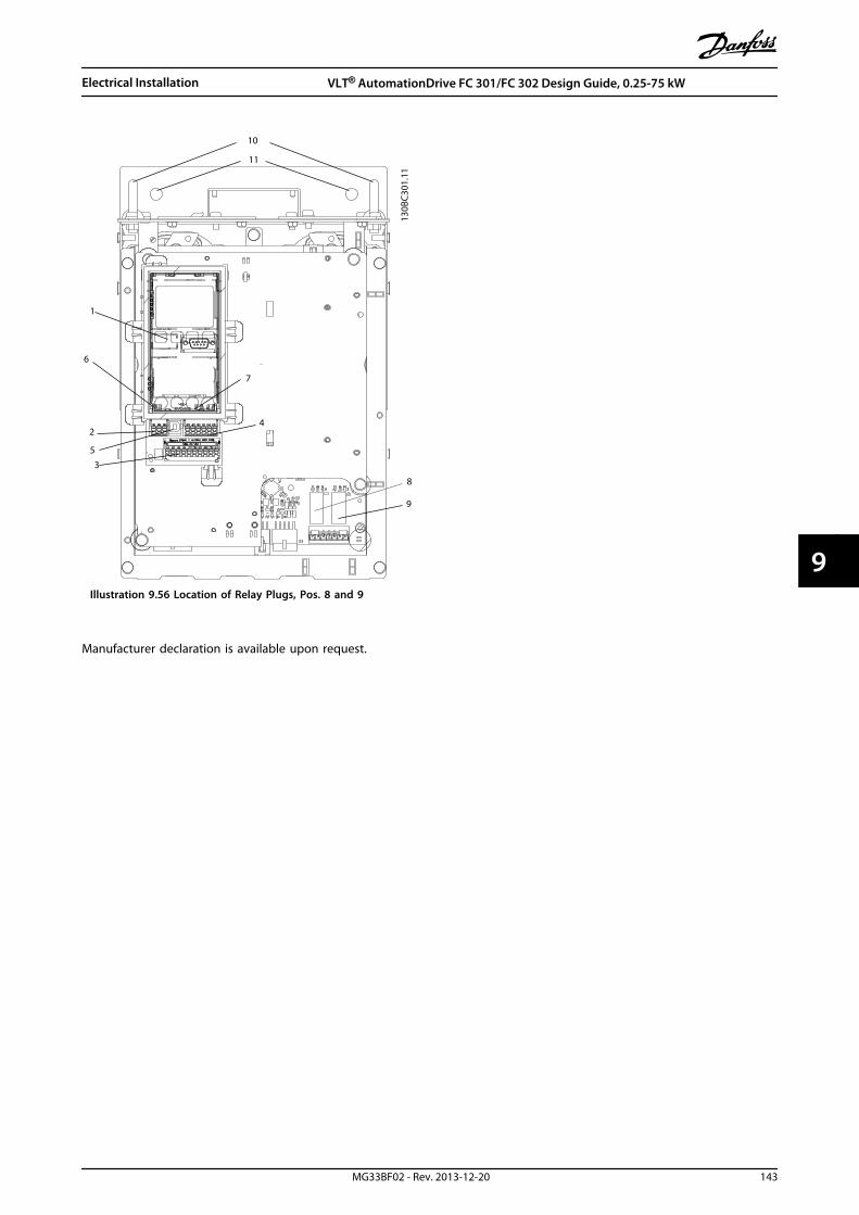
130B
C301
.11
1
2
3
4
5
6
7
8
9
10
11
Illustration 9.56 Location of Relay Plugs, Pos. 8 and 9
Manufacturer declaration is available upon request.
Electrical Installation VLT® AutomationDrive FC 301/FC 302 Design Guide, 0.25-75 kW
MG33BF02 - Rev. 2013-12-20 143
9 9

10 Application Examples
10.1 Commonly Used Applications
The examples in this section are intended as a quickreference for common applications.
• Parameter settings are the regional default valuesunless otherwise indicated (selected in0-03 Regional Settings)
• Parameters associated with the terminals andtheir settings are shown next to the drawings
• Where switch settings for analog terminals A53 orA54 are required, these are also shown
CAUTIONThermistors must use reinforced or double insulation tomeet PELV insulation requirements.
Parameters
FC
+24 V
+24 V
D IN
D IN
D IN
COM
D IN
D IN
D IN
D IN
+10 V
A IN
A IN
COM
A OUT
COM
12
13
18
19
20
27
29
32
33
37
50
53
54
55
42
39
130B
B929
.10 Function Setting
1-29 AutomaticMotorAdaptation(AMA)
[1] EnablecompleteAMA
5-12 Terminal 27Digital Input
[2]* Coastinverse
*=Default Value
Notes/comments: Parametergroup 1–2* Motor Data must beset according to motor
Table 10.1 AMA with T27 Connected
Parameters
FC
+24 V
+24 V
D IN
D IN
D IN
COM
D IN
D IN
D IN
D IN
+10 V
A IN
A IN
COM
A OUT
COM
12
13
18
19
20
27
29
32
33
37
50
53
54
55
42
39
130B
B930
.10 Function Setting
1-29 AutomaticMotorAdaptation(AMA)
[1] EnablecompleteAMA
5-12 Terminal 27Digital Input
[0] Nooperation
*=Default Value
Notes/comments: Parametergroup 1–2* Motor Data must beset according to motor
Table 10.2 AMA without T27 Connected
Parameters
FC
+24 V
+24 V
D IN
D IN
D IN
COM
D IN
D IN
D IN
D IN
+10 V
A IN
A IN
COM
A OUT
COM
12
13
18
19
20
27
29
32
33
37
50
53
54
55
42
39
A53
U - I
-10 - +10V
+
-
130B
B926
.10 Function Setting
6-10 Terminal 53Low Voltage
0.07 V*
6-11 Terminal 53High Voltage
10 V*
6-14 Terminal 53Low Ref./Feedb.Value
0 RPM
6-15 Terminal 53High Ref./Feedb.Value
1,500 RPM
*=Default Value
Notes/comments:
Table 10.3 Analog Speed Reference (Voltage)
Application Examples VLT® AutomationDrive FC 301/FC 302 Design Guide, 0.25-75 kW
144 MG33BF02 - Rev. 2013-12-20
1010
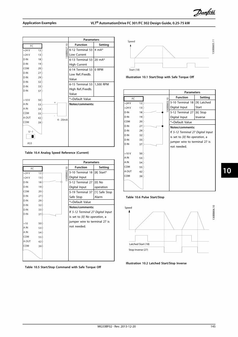
Parameters
130B
B927
.10
FC
+24 V
+24 V
D IN
D IN
D IN
COM
D IN
D IN
D IN
D IN
+10 VA IN
A IN
COM
A OUT
COM
12
13
18
19
20
27
29
32
33
37
50
53
54
55
42
39
A53
U - I
4 - 20mA
+
-
Function Setting
6-12 Terminal 53Low Current
4 mA*
6-13 Terminal 53High Current
20 mA*
6-14 Terminal 53Low Ref./Feedb.Value
0 RPM
6-15 Terminal 53High Ref./Feedb.Value
1,500 RPM
*=Default Value
Notes/comments:
Table 10.4 Analog Speed Reference (Current)
Parameters
FC
+24 V
+24 V
D IN
D IN
D IN
COM
D IN
D IN
D IN
D IN
+10
A IN
A IN
COM
A OUT
COM
12
13
18
19
20
27
29
32
33
37
50
53
54
55
42
39
130B
B802
.10 Function Setting
5-10 Terminal 18Digital Input
[8] Start*
5-12 Terminal 27Digital Input
[0] Nooperation
5-19 Terminal 37Safe Stop
[1] Safe StopAlarm
*=Default Value
Notes/comments:If 5-12 Terminal 27 Digital Inputis set to [0] No operation, ajumper wire to terminal 27 isnot needed.
Table 10.5 Start/Stop Command with Safe Torque Off
130B
B805
.11
Speed
Start (18)
Illustration 10.1 Start/Stop with Safe Torque Off
Parameters
FC
+24 V
+24 V
D IN
D IN
D IN
COM
D IN
D IN
D IN
D IN
+10 V
A IN
A IN
COM
A OUT
COM
12
13
18
19
20
27
29
32
33
37
50
53
54
55
42
39
130B
B803
.10 Function Setting
5-10 Terminal 18Digital Input
[9] LatchedStart
5-12 Terminal 27Digital Input
[6] StopInverse
*=Default Value
Notes/comments:If 5-12 Terminal 27 Digital Inputis set to [0] No operation, ajumper wire to terminal 27 isnot needed.
Table 10.6 Pulse Start/Stop
Speed
130B
B806
.10
Latched Start (18)
Stop Inverse (27)
Illustration 10.2 Latched Start/Stop Inverse
Application Examples VLT® AutomationDrive FC 301/FC 302 Design Guide, 0.25-75 kW
MG33BF02 - Rev. 2013-12-20 145
10 10

Parameters
FC
+24 V
+24 V
D IN
D IN
D IN
COM
D IN
D IN
D IN
D IN
+10 V
A IN
A IN
COM
A OUT
COM
12
13
18
19
20
27
29
32
33
37
50
53
54
55
42
39
130B
B934
.10 Function Setting
5-10 Terminal 18Digital Input
[8] Start
5-11 Terminal 19Digital Input
[10]Reversing*
5-12 Terminal 27Digital Input
[0] Nooperation
5-14 Terminal 32Digital Input
[16] Presetref bit 0
5-15 Terminal 33Digital Input
[17] Presetref bit 1
3-10 PresetReference
Preset ref. 0Preset ref. 1Preset ref. 2Preset ref. 3
25%50%75%100%
*=Default Value
Notes/comments:
Table 10.7 Start/Stop with Reversing and 4 Preset Speeds
Parameters
FC
+24 V
+24 V
D IN
D IN
D IN
COM
D IN
D IN
D IN
D IN
+10 V
A IN
A IN
COM
A OUT
COM
12
13
18
19
20
27
29
32
33
37
50
53
54
55
42
39
130B
B928
.10 Function Setting
5-11 Terminal 19Digital Input
[1] Reset
*=Default Value
Notes/comments:
Table 10.8 External Alarm Reset
Parameters
FC
+24 V
+24 V
D IN
D IN
D IN
COM
D IN
D IN
D IN
D IN
+10 V
A IN
A IN
COM
A OUT
COM
12
13
18
19
20
27
29
32
33
37
50
53
54
55
42
39
A53
U - I
≈ 5kΩ
130B
B683
.10 Function Setting
6-10 Terminal 53Low Voltage
0.07 V*
6-11 Terminal 53High Voltage
10 V*
6-14 Terminal 53Low Ref./Feedb.Value
0 RPM
6-15 Terminal 53High Ref./Feedb.Value
1,500 RPM
*=Default Value
Notes/comments:
Table 10.9 Speed Reference (using a Manual Potentiometer)
Parameters
FC
+24 V
+24 V
D IN
D IN
D IN
COM
D IN
D IN
D IN
D IN
+10 V
A IN
A IN
COM
A OUT
COM
12
13
18
19
20
27
29
32
33
37
50
53
54
55
42
39
130B
B804
.10 Function Setting
5-10 Terminal 18Digital Input
[8] Start*
5-12 Terminal 27Digital Input
[19] FreezeReference
5-13 Terminal 29Digital Input
[21] SpeedUp
5-14 Terminal 32Digital Input
[22] SpeedDown
*=Default Value
Notes/comments:
Table 10.10 Speed Up/Down
Application Examples VLT® AutomationDrive FC 301/FC 302 Design Guide, 0.25-75 kW
146 MG33BF02 - Rev. 2013-12-20
1010
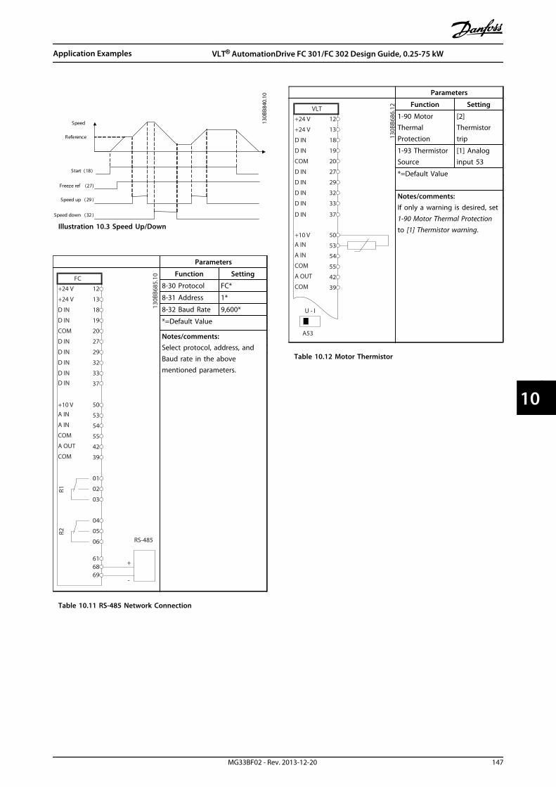
S t a r t ( 1 8 )
F r e e z e r e f ( 2 7 )
S p e e d u p ( 2 9 )
S p e e d d o w n ( 3 2 )
S p e e d
R e f e r e n c e
130B
B840
.10
Illustration 10.3 Speed Up/Down
Parameters
FC
+24 V
+24 V
D IN
D IN
D IN
COM
D IN
D IN
D IN
D IN
+10 V
A IN
A IN
COM
A OUT
COM
R1R2
12
13
18
19
20
27
29
32
33
37
50
53
54
55
42
39
01
02
03
04
05
06
-
616869
RS-485
+
130B
B685
.10 Function Setting
8-30 Protocol FC*
8-31 Address 1*
8-32 Baud Rate 9,600*
*=Default Value
Notes/comments:Select protocol, address, andBaud rate in the abovementioned parameters.
Table 10.11 RS-485 Network Connection
Parameters
130B
B686
.12
VLT
+24 V
+24 V
D IN
D IN
D IN
COM
D IN
D IN
D IN
+10 VA IN
A IN
COM
A OUT
COM
12
13
18
19
20
27
29
32
33
50
53
54
55
42
39
A53
U - I
D IN 37
Function Setting
1-90 MotorThermalProtection
[2]Thermistortrip
1-93 ThermistorSource
[1] Analoginput 53
*=Default Value
Notes/comments:If only a warning is desired, set1-90 Motor Thermal Protectionto [1] Thermistor warning.
Table 10.12 Motor Thermistor
Application Examples VLT® AutomationDrive FC 301/FC 302 Design Guide, 0.25-75 kW
MG33BF02 - Rev. 2013-12-20 147
10 10

Parameters
FC
+24 V
+24 V
D IN
D IN
D IN
COM
D IN
D IN
D IN
D IN
+10 V
A IN
A IN
COM
A OUT
COM
R1R2
12
13
18
19
20
27
29
32
33
37
50
53
54
55
42
39
01
02
03
04
05
06
130B
B839
.10 Function Setting
4-30 MotorFeedback LossFunction
[1] Warning
4-31 MotorFeedback SpeedError
100 RPM
4-32 MotorFeedback LossTimeout
5 s
7-00 Speed PIDFeedback Source
[2] MCB 102
17-11 Resolution(PPR)
1024*
13-00 SLController Mode
[1] On
13-01 StartEvent
[19] Warning
13-02 StopEvent
[44] Resetkey
13-10 Comparator Operand
[21] Warningno.
13-11 Comparator Operator
[1] ≈*
13-12 Comparator Value
90
13-51 SLController Event
[22]Comparator 0
13-52 SLController Action
[32] Setdigital out Alow
5-40 FunctionRelay
[80] SL digitaloutput A
*=Default Value
Notes/comments:If the limit in the feedbackmonitor is exceeded, Warning90 is issued. The SLC monitorsWarning 90 and in the casethat Warning 90 becomes TRUEthen relay 1 is triggered.External equipment mayindicate that service is required.If the feedback error goesbelow the limit again within 5s, the frequency convertercontinues and the warningdisappears. But relay 1 is stilltriggered until [Reset] on theLCP.
Table 10.13 Using SLC to Set a Relay
Parameters
FC
+24 V
+24 V
D IN
D IN
D IN
COM
D IN
D IN
D IN
D IN
+10 V
A IN
A IN
COM
A OUT
COMR1
R2
12
13
18
19
20
27
29
32
33
37
50
53
54
55
42
39
01
02
03
04
05
06
130B
B841
.10 Function Setting
1-00 Configu-ration Mode
[0] Speedopen loop
1-01 MotorControl Principle
[1] VVC+
5-40 FunctionRelay
[32] Mech.brake ctrl.
5-10 Terminal 18Digital Input
[8] Start*
5-11 Terminal 19Digital Input
[11] Startreversing
1-71 Start Delay 0.2
1-72 StartFunction
[5] VVC+/FLUXClockwise
1-76 StartCurrent
Im,n
2-20 ReleaseBrake Current
App.dependent
2-21 ActivateBrake Speed[RPM]
Half ofnominal slipof the motor
*=Default Value
Notes/comments:
Table 10.14 Mechanical Brake Control (Open Loop)
Start (18)
Start reversing (19)
Relay output
Speed
Time
Current
1-71 1-712-21 2-21
1-76
OpenClosed
130B
B842
.10
Illustration 10.4 Mechanical Brake Control (Open Loop)
Application Examples VLT® AutomationDrive FC 301/FC 302 Design Guide, 0.25-75 kW
148 MG33BF02 - Rev. 2013-12-20
1010

10.1.1 Closed Loop Drive System
A frequency converter system consist usually of moreelements such as
• Motor
• Gearbox
• Mechanical Brake
• Frequency converter
• Encoder as feed-back system
• Brake resistor for dynamic braking
• Transmission
• Load
Applications demanding mechanical brake control usuallyneed a brake resistor.
Motor Gearbox
Load
Transmission
Encoder Mech. brake
Brake resistor
130B
A12
0.10
Illustration 10.5 Example of FC 302 Closed Loop Speed Control
10.1.2 Programming of Torque Limit andStop
In applications with an external electro-mechanical brake,such as hoisting applications, it is possible to stop thefrequency converter via a 'standard' stop command andsimultaneously activate the external electro-mechanicalbrake. The example given below illustrates the programming offrequency converter connections.The external brake can be connected to relay 1 or 2.Program terminal 27 to [2] Coast, inverse or [3] Coast andReset, inverse, and program terminal 29 to [1] Terminalmode 29 Output and [27] Torque limit & stop.
DescriptionIf a stop command is active via terminal 18 and thefrequency converter is not at the torque limit, the motorramps down to 0 Hz.If the frequency converter is at the torque limit and a stopcommand is activated, terminal 29 Output (programmed to[27] Torque limit and stop) is activated. The signal toterminal 27 changes from 'logic 1' to 'logic 0', and themotor starts to coast, thereby ensuring that the hoist stopseven if the frequency converter itself cannot handle therequired torque (i.e. due to excessive overload).
• Start/stop via terminal 185-10 Terminal 18 Digital Input, [8] Start
• Quickstop via terminal 275-12 Terminal 27 Digital Input, [2] Coasting Stop,Inverse
• Terminal 29 Output5-02 Terminal 29 Mode, [1] Terminal 29 ModeOutput5-31 Terminal 29 Digital Output, [27] Torque Limit &Stop
• Relay output [0] (Relay 1)5-40 Function Relay, [32] Mechanical Brake Control
Application Examples VLT® AutomationDrive FC 301/FC 302 Design Guide, 0.25-75 kW
MG33BF02 - Rev. 2013-12-20 149
10 10
+24V
12 13 18 37
130B
A19
4.10
322719 29 33 20
P 5-40 [0] [32]
-
+
Relay 1 01 02 03
P 5-
10 [8
]
P 5-
12 [2
]
P 5-
02 [1
]
P 5-
31 [2
7]
GN
D
External
24 VDC
I max 0.1 Amp
Mechanical Brake
Connection
Start
Illustration 10.6 External Electro-mechanical Brake
10.1.3 Programming of Speed Control
The required motor speed is set via a potentiometerconnected to terminal 53. The speed range is 0 to 1500RPM corresponding to 0 to 10 V over the potentiometer.Starting and stopping is controlled by a switch connectedto terminal 18. The Speed PID monitors the actual RPM ofthe motor by using a 24 V (HTL) incremental encoder asfeedback. The feedback sensor is an encoder (1024 pulsesper revolution) connected to terminals 32 and 33.
M3
96 97 9998
91 92 93 95
50
12
L1 L2
L1
PEL3
W PEVU
F1
L2
L3
N
PE
18
53
37
55
203233
39
24 Vdc
130B
A17
4.10
Illustration 10.7 Example - Speed Control Connections
Application Examples VLT® AutomationDrive FC 301/FC 302 Design Guide, 0.25-75 kW
150 MG33BF02 - Rev. 2013-12-20
1010
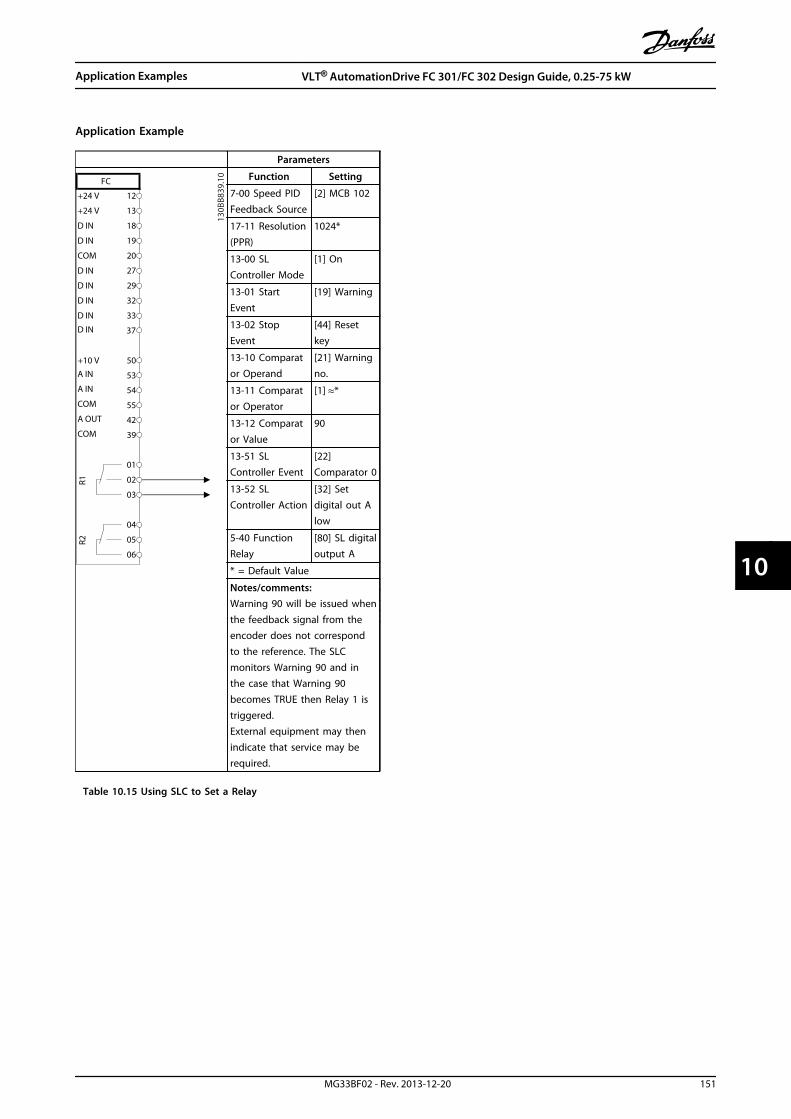
Application Example
Parameters
FC
+24 V
+24 V
D IN
D IN
D IN
COM
D IN
D IN
D IN
D IN
+10 V
A IN
A IN
COM
A OUT
COM
R1R2
12
13
18
19
20
27
29
32
33
37
50
53
54
55
42
39
01
02
03
04
05
06
130B
B839
.10 Function Setting
7-00 Speed PIDFeedback Source
[2] MCB 102
17-11 Resolution(PPR)
1024*
13-00 SLController Mode
[1] On
13-01 StartEvent
[19] Warning
13-02 StopEvent
[44] Resetkey
13-10 Comparator Operand
[21] Warningno.
13-11 Comparator Operator
[1] ≈*
13-12 Comparator Value
90
13-51 SLController Event
[22]Comparator 0
13-52 SLController Action
[32] Setdigital out Alow
5-40 FunctionRelay
[80] SL digitaloutput A
* = Default Value
Notes/comments:Warning 90 will be issued whenthe feedback signal from theencoder does not correspondto the reference. The SLCmonitors Warning 90 and inthe case that Warning 90becomes TRUE then Relay 1 istriggered.External equipment may thenindicate that service may berequired.
Table 10.15 Using SLC to Set a Relay
Application Examples VLT® AutomationDrive FC 301/FC 302 Design Guide, 0.25-75 kW
MG33BF02 - Rev. 2013-12-20 151
10 10

11 Options and Accessories
11.1 Communication Options
• VLT® PROFIBUS DP V1 MCA 101
• VLT® DeviceNet MCA 104
• VLT® CAN Open MCA 105
• VLT® EtherCAT MCA 124
• VLT® PROFIBUS Converter MCA 114
• VLT® PROFINET MCA 120
• VLT® EtherNet/IP MCA 121
• VLT® Modbus TCP MCA 122
• VLT® POWERLINK MCA 122
• VLT® DeviceNet Converter MCA 194
11.2 I/O, Feed-back and Safety Options
11.2.1 VLT® General Purpose I/O ModuleMCB 101
MCB 101 is used for extension of digital and analog inputsand outputs of FC 301 and FC 302.
Fit MCB 101 into slot B in the VLT® AutomationDrive.
Contents:
• MCB 101 option module
• Extended fixture for LCP
• Terminal cover
General Purpose I/O
SW. ver. XX.XX
MCB 101 FC Series
Code No. 130BXXXX
B slot
X30/
AIN
4
7 8654321 9 10 11 12
AIN
3
GN
D(2
)
24V
AOU
T2
DO
UT4
DO
UT3
GN
D(1
)
DIN
7
COM
DIN
DIN
8
DIN
9
130B
A20
8.10
Illustration 11.1 MCB 101 Option
11.2.1.1 Galvanic Isolation in MCB 101
Digital/analog inputs are galvanically isolated from otherinputs/outputs on the MCB 101 and in the control card ofthe frequency converter. Digital/analog outputs in the MCB101 are galvanically isolated from other inputs/outputs onthe MCB 101, but not from these on the control card ofthe frequency converter.
If the digital inputs 7, 8 or 9 are to be switched by use ofthe internal 24 V power supply (terminal 9), establishconnection between terminals 1 and 5, see Illustration 11.2.
130B
A20
9.10
1 2 3 4 5 6 7 8 9 10 11 12
COM
DIN
DIN
7
DIN
8
DIN
9
GN
D(1
)
DO
UT3
0/24
VDC
DO
UT4
0/24
VDC
AOU
T20/
4-20
mA
24V
GN
D(2
)
AIN
3
AIN
4
RIN=5kohm
RIN=10kohm
0-10VDC
0-10VDC
0V 24V
0V 24V
24V DC0V
0V24V DC
<500
ohm
>600
ohm
>600
ohm
X30/
DIG IN DIG & ANALOGOUT
ANALOGIN
CPU
CAN
BU
S
CPU
Control card (FC 100/200/300)
General PurposeI/O option MCB 101
PLC(PNP)
PLC(NPN)
Illustration 11.2 Principle Diagram
Options and Accessories VLT® AutomationDrive FC 301/FC 302 Design Guide, 0.25-75 kW
152 MG33BF02 - Rev. 2013-12-20
1111

Digital input - terminal X30/1-4Number of digital inputs 3Terminal number X30.2, X30.3, X30.4Logic PNP or NPNVoltage level 0-24 V DCVoltage level, logic'0' PNP (GND = 0 V) < 5 V DCVoltage level, logic'1' PNP (GND = 0 V) > 10 V DCVoltage level, logic '0' NPN (GND = 24 V) < 14 V DCVoltage level, logic '1' NPN (GND = 24 V) > 19 V DCMaximum voltage on input 28 V continousPulse frequency range 0-110 kHzDuty cycle, min. pulse width 4.5 msInput impedance > 2 kΩ
Analog input - terminal X30/11, 12Number of analog inputs 2Terminal number X30.11, X30.12Modes VoltageVoltage level 0-10 VInput impedance > 10 kΩMax. voltage 20 VResolution for analog inputs 10 bit (+ sign)Accuracy of analog inputs Max. error 0.5% of full scaleBandwidth FC 301: 20 Hz/ FC 302: 100 Hz
Digital outputs - terminal X30/6, 7Number of digital outputs 2Terminal number X30.6, X30.7Voltage level at digital/frequency output 0-24 VMax. output current 40 mAMax. load ≥ 600 ΩMax. capacitive load < 10 nFMinimum output frequency 0 HzMaximum output frequency ≤ 32 kHzAccuracy of frequency output Max. error: 0.1 % of full scale
Analog output - terminal X30/8Number of analog outputs 1Terminal number X30.8Current range at analog output 0-20 mAMax. load GND - analog output 500 ΩAccuracy on analog output Max. error: 0.5 % of full scaleResolution on analog output 12 bit
Options and Accessories VLT® AutomationDrive FC 301/FC 302 Design Guide, 0.25-75 kW
MG33BF02 - Rev. 2013-12-20 153
11 11
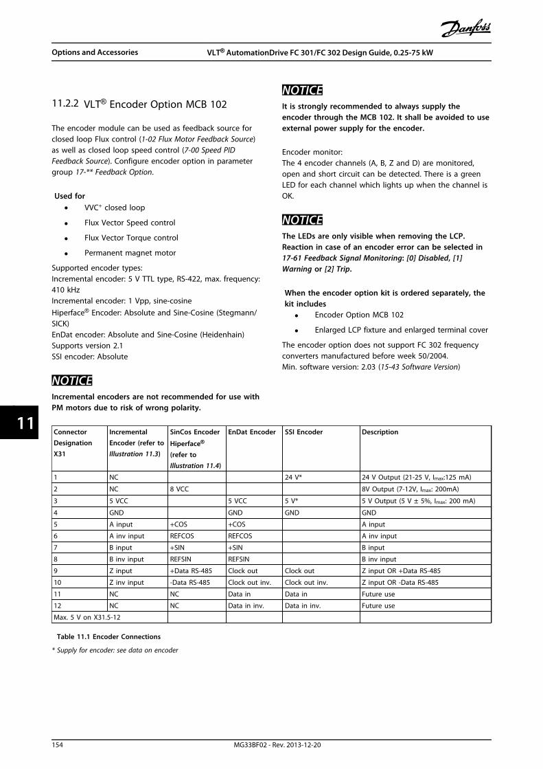
11.2.2 VLT® Encoder Option MCB 102
The encoder module can be used as feedback source forclosed loop Flux control (1-02 Flux Motor Feedback Source)as well as closed loop speed control (7-00 Speed PIDFeedback Source). Configure encoder option in parametergroup 17-** Feedback Option.
Used for• VVC+ closed loop
• Flux Vector Speed control
• Flux Vector Torque control
• Permanent magnet motor
Supported encoder types:Incremental encoder: 5 V TTL type, RS-422, max. frequency:410 kHzIncremental encoder: 1 Vpp, sine-cosineHiperface® Encoder: Absolute and Sine-Cosine (Stegmann/SICK)EnDat encoder: Absolute and Sine-Cosine (Heidenhain)Supports version 2.1SSI encoder: Absolute
NOTICEIncremental encoders are not recommended for use withPM motors due to risk of wrong polarity.
NOTICEIt is strongly recommended to always supply theencoder through the MCB 102. It shall be avoided to useexternal power supply for the encoder.
Encoder monitor:The 4 encoder channels (A, B, Z and D) are monitored,open and short circuit can be detected. There is a greenLED for each channel which lights up when the channel isOK.
NOTICEThe LEDs are only visible when removing the LCP.Reaction in case of an encoder error can be selected in17-61 Feedback Signal Monitoring: [0] Disabled, [1]Warning or [2] Trip.
When the encoder option kit is ordered separately, thekit includes
• Encoder Option MCB 102
• Enlarged LCP fixture and enlarged terminal cover
The encoder option does not support FC 302 frequencyconverters manufactured before week 50/2004.Min. software version: 2.03 (15-43 Software Version)
ConnectorDesignationX31
IncrementalEncoder (refer toIllustration 11.3)
SinCos Encoder
Hiperface®
(refer toIllustration 11.4)
EnDat Encoder SSI Encoder Description
1 NC 24 V* 24 V Output (21-25 V, Imax:125 mA)
2 NC 8 VCC 8V Output (7-12V, Imax: 200mA)
3 5 VCC 5 VCC 5 V* 5 V Output (5 V ± 5%, Imax: 200 mA)
4 GND GND GND GND
5 A input +COS +COS A input
6 A inv input REFCOS REFCOS A inv input
7 B input +SIN +SIN B input
8 B inv input REFSIN REFSIN B inv input
9 Z input +Data RS-485 Clock out Clock out Z input OR +Data RS-485
10 Z inv input -Data RS-485 Clock out inv. Clock out inv. Z input OR -Data RS-485
11 NC NC Data in Data in Future use
12 NC NC Data in inv. Data in inv. Future use
Max. 5 V on X31.5-12
Table 11.1 Encoder Connections
* Supply for encoder: see data on encoder
Options and Accessories VLT® AutomationDrive FC 301/FC 302 Design Guide, 0.25-75 kW
154 MG33BF02 - Rev. 2013-12-20
1111

1 2 3 12
130B
A16
3.11
754 6 8 9 10 11
24 V 8 V 5 V GND A A B B Z Z D D
Illustration 11.3 Incremental Encoder
NOTICEMax. cable length 150 m.
Us
7-12
V (re
d)
GN
D (b
lue)
+CO
S (p
ink)
REFC
OS
(bla
ck)
+SIN
(whi
te)
REFS
IN (b
row
n)
Dat
a +R
S 48
5 (g
ray)
Dat
a -R
S 48
5 (g
reen
)
1 2 3 12754 6 8 9 10 11
130B
A16
4.10
Illustration 11.4 SinCos Encoder Hiperface
130B
A11
9.10
B
A
A
B
A
B
B
A
Illustration 11.5 Rotation Direction
11.2.3 VLT® Resolver Option MCB 103
Resolver Option MCB 103 is used for interfacing resolvermotor feedback to VLT® AutomationDrive. Resolvers areused basically as motor feedback device for PermanentMagnet brushless synchronous motors.
When the Resolver option is ordered separately, the kitincludes
• Resolver Option MCB 103
• Enlarged LCP fixture and enlarged terminal cover
Selection of parameters: 17-5* Resolver Interface.
Resolver Option MCB 103 supports a various number ofresolver types.
Resolver Poles 17-50 Poles: 2 *2
Resolver InputVoltage
17-51 Input Voltage: 2.0–8.0 Vrms *7.0 Vrms
Resolver InputFrequency
17-52 Input Frequency: 2–15 kHz*10.0 kHz
Transformation ratio 17-53 Transformation Ratio: 0.1–1.1 *0.5
Secondary inputvoltage
Max 4 Vrms
Secondary load App. 10 kΩ
Table 11.2 Resolver Specifications
Options and Accessories VLT® AutomationDrive FC 301/FC 302 Design Guide, 0.25-75 kW
MG33BF02 - Rev. 2013-12-20 155
11 11

Resolver InputSW. ver. X.XX
MCB 103
Code No.
Option B
Rotor
Resolver stator
Motor
LED 1 REF OKLED 2 COS OKLED 3 SIN OKLED NA
130B
A24
7.11
REF+REF-
COS-COS+
SIN+SIN- S4
S2S3S1R2R1
COS-
COS+
REF+
REF-
SIN
+SI
N-
A+
A-
B+ B- Z+ Z-
X32/ 31 2 4 5 116 87 109 12
1 2 3 4
S1
S3
S4 S2
R1
R2
θ
Illustration 11.6 MCB 103 Resolver Input
LED indicatorsLED 1 is on when the reference signal is OK to resolver.LED 2 is on when Cosinus signal is OK from resolver.LED 3 is on when Sinus signal is OK from resolver.
The LEDs are active when 17-61 Feedback Signal Monitoringis set to [1] Warning or [2] Trip.
130B
T102
.10
Illustration 11.7 Permanent Magnet (PM) Motor with Resolveras Speed Feedback
Set-up exampleIn this example a Permanent Magnet (PM) Motor is usedwith resolver as speed feedback. A PM motor must usuallyoperate in flux mode.WiringThe max cable length is 150 m when a twisted pair type ofcable is used.
NOTICEResolver cables must be screened and separated fromthe motor cables.
NOTICEThe screen of the resolver cable must be correctlyconnected to the de-coupling plate and connected tochassis (ground) on the motor side.
NOTICEAlways use screened motor cables and brake choppercables.
Options and Accessories VLT® AutomationDrive FC 301/FC 302 Design Guide, 0.25-75 kW
156 MG33BF02 - Rev. 2013-12-20
1111

1-00 ConfigurationMode
[1] Speed closed loop
1-01 Motor ControlPrinciple
[3] Flux with feedback
1-10 MotorConstruction
[1] PM, non salient SPM
1-24 Motor Current Nameplate
1-25 Motor NominalSpeed
Nameplate
1-26 Motor Cont. RatedTorque
Nameplate
AMA is not possible on PM motors
1-30 Stator Resistance(Rs)
Motor data sheet
30-80 d-axis Inductance(Ld)
Motor data sheet (mH)
1-39 Motor Poles Motor data sheet
1-40 Back EMF at 1000RPM
Motor data sheet
1-41 Motor Angle Offset Motor data sheet (Usually zero)
17-50 Poles Resolver data sheet
17-51 Input Voltage Resolver data sheet
17-52 Input Frequency Resolver data sheet
17-53 TransformationRatio
Resolver data sheet
17-59 Resolver Interface [1] Enabled
Table 11.3 Parameters to Adjust
11.2.4 VLT® Relay Card MCB 105
The Relay Option MCB 105 includes 3 pieces of SPDT contacts and must be fitted into option slot B.
Electrical DataMax terminal load (AC-1)1) (Resistive load) 240 V AC 2 AMax terminal load (AC-15 )1) (Inductive load @ cosφ 0.4) 240 V AC 0.2 AMax terminal load (DC-1)1) (Resistive load) 24 V DC 1 AMax terminal load (DC-13)1) (Inductive load) 24 V DC 0.1 AMin terminal load (DC) 5 V 10 mAMax switching rate at rated load/min load 6 min-1/20 s-1
1) IEC 947 part 4 and 5
When the relay option kit is ordered separately the kitincludes
• Relay Module MCB 105
• Enlarged LCP fixture and enlarged terminal cover
• Label for covering access to switches S201, S202and S801
• Cable strips for fastening cables to relay module
Options and Accessories VLT® AutomationDrive FC 301/FC 302 Design Guide, 0.25-75 kW
MG33BF02 - Rev. 2013-12-20 157
11 11

2
130B
A70
9.11
1LABEL
Remove jumper to activate Safe Stop
1213
1819
2729
3332
20
3942
5053
54
6168
CAUTION:SEE MANUAL / RCD and high leakage current
VOIR MANUAL / Fransk tekst
WARNING:Stored charge / “Fransk tekst” (4 min.)
LISTED 76x1 134261
INDUSTRIAL CONTROL EQUIPMENT
SEE MANUAL FOR PREFUSE TUPE IN UL
APPLICATIONS
T/C : CIAXXXPT5B20BR1DBF00A00
P/N : XXXN1100 S/N: 012815G432
IN: 3x380-480V 50/60Hz 14.9A
OUT: 3x0-Uin 0-1000Hz 16.0A 11.1 kVA
CHASIS/IP20 Tamb Max 45C/113F MADE IN DENMARK
9Ø
9Ø
Ø6
1 IMPORTANT ! The label MUST be placed on the LCP frameas shown (UL approved).
2 Relay card
Illustration 11.8 Enclosure Types A2-A3-B3
2
130B
A71
0.11
1LABEL Remove jumper to activate Safe Stop
1312 18 19 27 32 38 228
42395350 5
61 6
9Ø
9Ø
DC- DC+
1 IMPORTANT ! The label MUST be placed on the LCP frameas shown (UL approved).
2 Relay card
Illustration 11.9 Enclosure Types A5-B1-B2-B4-C1-C2-C3-C4
WARNINGWarning Dual supply
How to add the Relay Card MCB 105 Option:1. Disconnect power to the frequency converter.
2. Disconnect power to the live part connections onrelay terminals.
3. Remove the LCP, the terminal cover and the LCPfixture from the frequency converter.
4. Fit the MCB 105 option in slot B.
5. Connect the control cables and fasten the cableswith the enclosed cable strips.
6. Make sure the length of the stripped wire iscorrect (see Illustration 11.11).
7. Do not mix live parts (high voltage) with controlsignals (PELV).
8. Fit the enlarged LCP fixture and enlargedterminal cover.
9. Replace the LCP.
10. Connect power to the frequency converter.
11. Select the relay functions in 5-40 Function Relay[6-8], 5-41 On Delay, Relay [6-8] and 5-42 OffDelay, Relay [6-8].
NOTICEArray [6] is relay 7, array [7] is relay 8, and array [8] isrelay 9
NOTICETo access RS-485 termination switch S801 or current/voltage switches S201/S202, dismount the relay card (seeIllustration 11.8 and Illustration 11.9, position 2).
Relay 7
NC NCNC
Relay 9Relay 8
1 2 3 12
130B
A16
2.10
754 6 8 9 10 11
Illustration 11.10 Relays
130B
A17
7.10
8-9mm
2mm
Illustration 11.11 Correct Wire Inserting
Options and Accessories VLT® AutomationDrive FC 301/FC 302 Design Guide, 0.25-75 kW
158 MG33BF02 - Rev. 2013-12-20
1111

1 1 1
1 102 3 4 5 6 7 8 9 1211
2 2 3
1 1 1
1 102 3 4 5 6 7 8 9 1211
3 3 3
1 1 1
1 102 3 4 5 6 7 8 9 1211
2 2 2
130B
A17
6.11
1 NC
2 Live part
3 PELV
Illustration 11.12 Correct Relay Wiring
NOTICEDo not combine 24/48 V systems with high-voltagesystems.
Options and Accessories VLT® AutomationDrive FC 301/FC 302 Design Guide, 0.25-75 kW
MG33BF02 - Rev. 2013-12-20 159
11 11

11.2.5 VLT® Safe PLC Interface Option MCB108
The Safe PLC Interface Option MCB 108 is designed to bebuilt-in between the Safe dual pole (plus/minus) on theSafe PLC and the Safe Stop input on FC 302. The Safe PLCinterface allows the safe output on the Safe PLC tomaintain the test pulses on the plus and minus outputwithout impacting the sensor signal to safe stop T37.It can be used in combination with safety devices to satisfythe requirement of IEC61800-5-2 SIL 2, ISO13849-1 cat. 3for Safe Torque Off (STO).
The option module MCB 108 is galvanically isolated via aninternal DC/DC converter and it can be fitted into optionslot B.
Input voltage (DC) 18-28 V DCTypical current input (DC) 60 mAMax. current input (DC) 110 mA DCMax. current inrush (DC) 500 mA DCOutput voltage (DC) 20 V DC@Vin = 24 VTurn on delay 1 msTurn off delay 3 ms
Observe the following precautions
• The FC 302 with MCB 108 (including theconnections between X31/9 and Terminal 37)must be placed inside an IP54 enclosure.
• Safe Stop activation (i.e. removal of 24 V DCvoltage supply to terminal 37 by removingvoltage to dual pole input of MCB 108) does notprovide electrical safety.
• The safety device connected to the dual poleinput of the MCB 108 must fulfill therequirements of cat. 3 / PL d according to ISO13849-1 for interrupting the voltage/current tothe MCB 108. This also applies for theconnections between the MCB 108 and the safetydevice.
• Read and follow the instructions for the safetydevice to connect it properly to MCB 108.
Illustration 11.13 Option Module Safe PLC Interface MCB 108
Safe PLC MCB 108 FC 302
24 V DCP - ControlP - Monitor
M - Monitor
M - MonitorGND
X31/2
X31/3 GND GX
X31/9
X31/10
37
20
Safechannel
130B
A83
1.11
Illustration 11.14 Safe PLC Interface MCB 108 Connection
Options and Accessories VLT® AutomationDrive FC 301/FC 302 Design Guide, 0.25-75 kW
160 MG33BF02 - Rev. 2013-12-20
1111
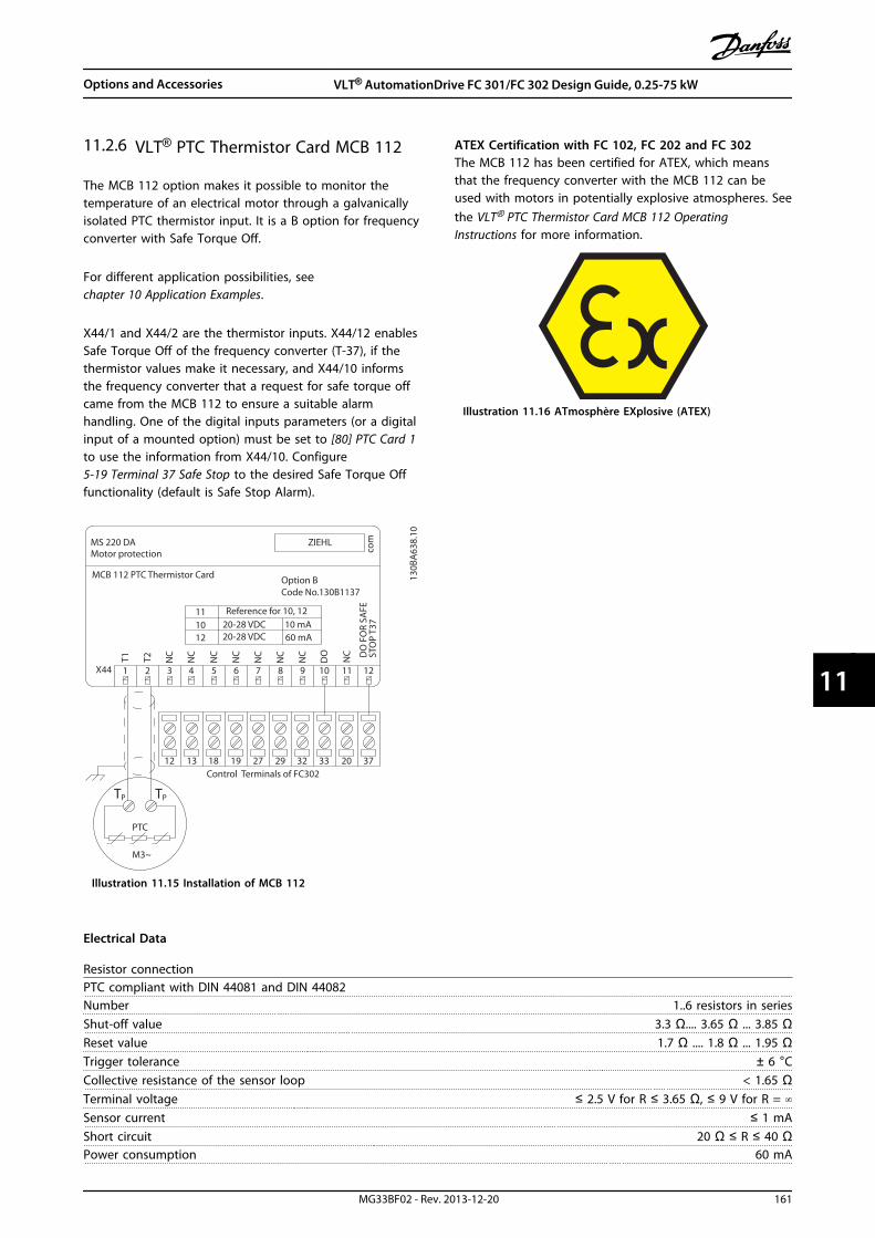
11.2.6 VLT® PTC Thermistor Card MCB 112
The MCB 112 option makes it possible to monitor thetemperature of an electrical motor through a galvanicallyisolated PTC thermistor input. It is a B option for frequencyconverter with Safe Torque Off.
For different application possibilities, seechapter 10 Application Examples.
X44/1 and X44/2 are the thermistor inputs. X44/12 enablesSafe Torque Off of the frequency converter (T-37), if thethermistor values make it necessary, and X44/10 informsthe frequency converter that a request for safe torque offcame from the MCB 112 to ensure a suitable alarmhandling. One of the digital inputs parameters (or a digitalinput of a mounted option) must be set to [80] PTC Card 1to use the information from X44/10. Configure5-19 Terminal 37 Safe Stop to the desired Safe Torque Offfunctionality (default is Safe Stop Alarm).
MS 220 DA
1110 20-28 VDC 10 mA12 20-28 VDC 60 mA
comZIEHL
X44
12 13 18 19 27 29 32 33 20 37
3
NC
4
NC
5
NC
6
NC
7
NC
8
NC
9
NC
10 11
NC
121
T1
2
T2
TP TP
PTC
M3~
130B
A63
8.10
DO
Motor protection
MCB 112 PTC Thermistor Card Option B
Reference for 10, 12
DO
FO
R SA
FEST
OP
T37
Code No.130B1137
Control Terminals of FC302
Illustration 11.15 Installation of MCB 112
ATEX Certification with FC 102, FC 202 and FC 302The MCB 112 has been certified for ATEX, which meansthat the frequency converter with the MCB 112 can beused with motors in potentially explosive atmospheres. Seethe VLT® PTC Thermistor Card MCB 112 OperatingInstructions for more information.
Illustration 11.16 ATmosphère EXplosive (ATEX)
Electrical Data
Resistor connectionPTC compliant with DIN 44081 and DIN 44082Number 1..6 resistors in seriesShut-off value 3.3 Ω.... 3.65 Ω ... 3.85 ΩReset value 1.7 Ω .... 1.8 Ω ... 1.95 ΩTrigger tolerance ± 6 °CCollective resistance of the sensor loop < 1.65 ΩTerminal voltage ≤ 2.5 V for R ≤ 3.65 Ω, ≤ 9 V for R = ∞Sensor current ≤ 1 mAShort circuit 20 Ω ≤ R ≤ 40 ΩPower consumption 60 mA
Options and Accessories VLT® AutomationDrive FC 301/FC 302 Design Guide, 0.25-75 kW
MG33BF02 - Rev. 2013-12-20 161
11 11

Testing conditionsEN 60 947-8Measurement voltage surge resistance 6000 VOvervoltage category IIIPollution degree 2Measurement isolation voltage Vbis 690 VReliable galvanic isolation until Vi 500 VPerm. ambient temperature -20 °C to +60 °C
EN 60068-2-1 Dry heatMoisture 5-95%, no condensation permissibleVibration resistance 10 to 1000 Hz 1.14 gShock resistance 50 g
Safety system valuesEN 61508 for Tu = 75 °C ongoingSIL 2 for maintenance cycle of 2 years
1 for maintenance cycle of 3 yearsHFT 0PFD (for yearly functional test) 4.10 *10-3
SFF 78%λs + λDD 8494 FITλDU 934 FITOrdering number 130B1137
11.2.7 VLT® Extended Relay Card MCB 113
The MCB 113 adds 7 digital inputs, 2 analog outputs and 4SPDT relays to the standard I/O of the frequency converterfor increased flexibility and to comply with the GermanNAMUR NE37 recommendations.The MCB 113 is a standard C1 option for the VLT®
AutomationDrive and is automatically detected aftermounting.
130B
A96
5.1012
1110
98
76
54
32
14321 12111098765432121 13 14
+ - + - + - + - + - + - + - + - + - + -A03
A03
Ext.
24 V
DC
DI1
DI2
DI3
DI4
DI5
DI6
DI7
X45/ X48/ X46/
X47/
Rela
y 3
Rela
y 4
Rela
y 5
Rela
y 6
Illustration 11.17 Electrical Connections of MCB 113
MCB 113 can be connected to an external 24 V on X58/ toensure galvanical isolation between the VLT®
AutomationDrive and the option card. If galvanicalisolation is not needed, the option card can be suppliedthrough internal 24 V from the frequency converter.
NOTICEIt is OK to combine 24 V signals with high voltagesignals in the relays as long as there is one unused relayin-between.
To setup MCB 113, use parameter groups 5-1* Digital input,6-7* Analog Output 3, 6-8* Analog output 4, 14-8* Options,5-4* Relays and 16-6* Inputs and Outputs.
NOTICEIn parameter group 5-4* Relay, Array [2] is relay 3, array[3] is relay 4, array [4] is relay 5 and array [5] is relay 6
Options and Accessories VLT® AutomationDrive FC 301/FC 302 Design Guide, 0.25-75 kW
162 MG33BF02 - Rev. 2013-12-20
1111
Electrical Data
RelaysNumbers 4 SPDTLoad at 250 V AC/30 V DC 8 ALoad at 250 V AC/30 V DC with cos = 0.4 3.5 AOver voltage category (contact-earth) IIIOver voltage category (contact-contact) IICombination of 250 V and 24 V signals Possible with one unused relay in-betweenMaximum thru-put delay 10 msIsolated from ground/chassis for use on IT mains systems
Digital InputsNumbers 7Range 0/24 VMode PNP/ NPNInput impedance 4 kWLow trigger level 6.4 VHigh trigger level 17 VMaximum thru-put delay 10 ms
Analog OutputsNumbers 2Range 0/4 -20 mAResolution 11 bitLinearity <0.2%
11.2.8 VLT® Sensor Input Option MCB 114
The sensor input option card MCB 114 can be used in thefollowing cases:
• Sensor input for temperature transmitters PT100and PT1000 for monitoring bearing temperatures
• As general extension of analog inputs with oneadditional input for multi-zone control or differ-ential pressure measurements
• Support extended PID controllers with I/Os for setpoint, transmitter/sensor inputs
Typical motors, designed with temperature sensors toprotect bearings from being overloaded, are fitted with 3PT100/1000 temperature sensors; one in front, one in theback end bearing, and one in the motor windings. TheDanfoss option MCB 114 supports 2- or 3-wire sensors withindividual temperature limits for under/over temperature.An auto detection of sensor type, PT100 or PT1000 takesplace at power up.
The option can generate an alarm if the measuredtemperature is either below the low limit or above thehigh limit specified by the user. The individual measuredtemperature on each sensor input can be read out in thedisplay or by readout parameters. If an alarm occurs, therelays or digital outputs can be programmed to be active
high by selecting [21] Thermal Warning in parameter group5-** Digital In/Out.
A fault condition has a common warning/alarm numberassociated with it, which is Alarm/Warning 20, Temp. inputerror. Any present output can be programmed to be activein case the warning or alarm appears.
Options and Accessories VLT® AutomationDrive FC 301/FC 302 Design Guide, 0.25-75 kW
MG33BF02 - Rev. 2013-12-20 163
11 11

11.2.8.1 Electrical and Mechanical Specifications
Analogue InputNumber of analogue inputs 1Format 0–20 mA or 4–20 mAWires 2Input impedance <200 ΩSample rate 1 kHz3rd order filter 100 Hz at 3 dBThe option is able to supply the analogue sensor with 24 VDC (terminal 1).
Temperature Sensor InputNumber of analogue inputs supporting PT100/1000 3Signal type PT100/1000Connection PT 100 2 or 3 wire/PT1000 2 or 3 wireFrequency PT100 and PT1000 input 1 Hz for each channelResolution 10 bit
Temperature range-50–204 °C-58–399 °F
Galvanic IsolationThe sensors to be connected are expected to be galvanically isolated from the mains voltagelevel IEC 61800-5-1 and UL508C
CablingMaximum signal cable length 500 m
11.2.8.2 Electrical Wiring
MCB 114 Sensor Input Option B
SW. ver. xx.xx Code No. 130B1272
VDD
I IN
GND
TEMP
1
WIRE
1
GND
TEMP 2
WIRE 2
GND
TEMP 3
WIRE 3
GND
X48/ 1 2 3 4 5 6 7 8 9 10 11 12
4-20mA
2 or 3
wire2 or 3
wire
2 or 3
wire
2 or 3
wire
13
0B
B3
26
.10
Terminal Name Function
1 VDD 24 V DC to supply 4-20 mAsensor
2 I in 4-20 mA input
3 GND Analog input GND
4, 7, 10 Temp 1, 2, 3 Temperature input
5, 8, 11 Wire 1, 2, 3 3rd wire input if 3 wiresensors are used
6, 9, 12 GND Temp. input GND
Illustration 11.18 MCB 114
Options and Accessories VLT® AutomationDrive FC 301/FC 302 Design Guide, 0.25-75 kW
164 MG33BF02 - Rev. 2013-12-20
1111
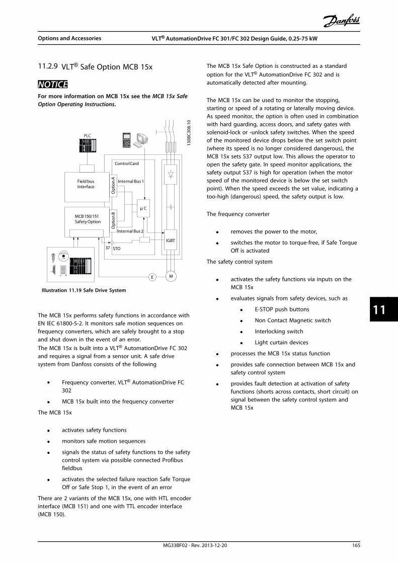
11.2.9 VLT® Safe Option MCB 15x
NOTICEFor more information on MCB 15x see the MCB 15x SafeOption Operating Instructions.
130B
C30
8.10
Field busInterface
MCB 150/151Safety Option
Opt
ion
AO
ptio
n B
Internal Bus 1
Internal Bus 2
μ C
Control Card
IGBT
STO37
E M
PLC
EMER ENCYG
ST OP
Illustration 11.19 Safe Drive System
The MCB 15x performs safety functions in accordance withEN IEC 61800-5-2. It monitors safe motion sequences onfrequency converters, which are safely brought to a stopand shut down in the event of an error.The MCB 15x is built into a VLT® AutomationDrive FC 302and requires a signal from a sensor unit. A safe drivesystem from Danfoss consists of the following
• Frequency converter, VLT® AutomationDrive FC302
• MCB 15x built into the frequency converter
The MCB 15x
• activates safety functions
• monitors safe motion sequences
• signals the status of safety functions to the safetycontrol system via possible connected Profibusfieldbus
• activates the selected failure reaction Safe TorqueOff or Safe Stop 1, in the event of an error
There are 2 variants of the MCB 15x, one with HTL encoderinterface (MCB 151) and one with TTL encoder interface(MCB 150).
The MCB 15x Safe Option is constructed as a standardoption for the VLT® AutomationDrive FC 302 and isautomatically detected after mounting.
The MCB 15x can be used to monitor the stopping,starting or speed of a rotating or laterally moving device.As speed monitor, the option is often used in combinationwith hard guarding, access doors, and safety gates withsolenoid-lock or -unlock safety switches. When the speedof the monitored device drops below the set switch point(where its speed is no longer considered dangerous), theMCB 15x sets S37 output low. This allows the operator toopen the safety gate. In speed monitor applications, thesafety output S37 is high for operation (when the motorspeed of the monitored device is below the set switchpoint). When the speed exceeds the set value, indicating atoo-high (dangerous) speed, the safety output is low.
The frequency converter
• removes the power to the motor,
• switches the motor to torque-free, if Safe TorqueOff is activated
The safety control system
• activates the safety functions via inputs on theMCB 15x
• evaluates signals from safety devices, such as
• E-STOP push buttons
• Non Contact Magnetic switch
• Interlocking switch
• Light curtain devices
• processes the MCB 15x status function
• provides safe connection between MCB 15x andsafety control system
• provides fault detection at activation of safetyfunctions (shorts across contacts, short circuit) onsignal between the safety control system andMCB 15x
Options and Accessories VLT® AutomationDrive FC 301/FC 302 Design Guide, 0.25-75 kW
MG33BF02 - Rev. 2013-12-20 165
11 11
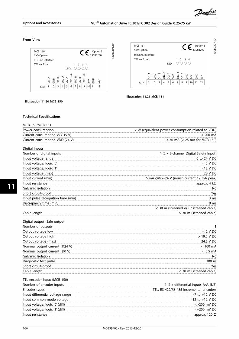
Front View
130B
C30
6.10
MCB 150Safe Option
SW. ver. 1 .xx
Option B130B3280
LED:1 2 3 4
TTL Enc. interface
Y30/
DI1
A
GN
D
DI1
B
ENC
A
DI2
A
ENC
nA
ENC
B
DI2
B
ENC
nB
24V
GN
D
S37
1 2 3 4 5 6 7 8 9 10 11 12
Illustration 11.20 MCB 150
130B
C30
7.10
MCB 151
Safe Option
SW. ver. 1 .xx
Option B130B3290
LED:
1 2 3 4
HTL Enc. interface
Y31/
DI1
A
GN
D
DI1
B
ENC
A
DI2
A
ENC
B
DI2
B
24V
GN
D
S37
1 2 3 4 5 6 7 8 9 10 11 12
GN
D
GN
D
Illustration 11.21 MCB 151
Technical Specifications
MCB 150/MCB 151Power consumption 2 W (equivalent power consumption related to VDD)Current consumption VCC (5 V) < 200 mACurrent consumption VDD (24 V) < 30 mA (< 25 mA for MCB 150)
Digital inputsNumber of digital inputs 4 (2 x 2-channel Digital Safety Input)Input voltage range 0 to 24 V DCInput voltage, logic '0' < 5 V DCInput voltage, logic '1' > 12 V DCInput voltage (max) 28 V DCInput current (min) 6 mA @Vin=24 V (inrush current 12 mA peak)Input resistance approx. 4 kΩGalvanic isolation NoShort circuit-proof YesInput pulse recognition time (min) 3 msDiscrepancy time (min) 9 ms
Cable length< 30 m (screened or unscreened cable)
> 30 m (screened cable)
Digital output (Safe output)Number of outputs 1Output voltage low < 2 V DCOutput voltage high > 19.5 V DCOutput voltage (max) 24.5 V DCNominal output current (@24 V) < 100 mANominal output current (@0 V) < 0.5 mAGalvanic Isolation NoDiagnostic test pulse 300 usShort circuit-proof YesCable length < 30 m (screened cable)
TTL encoder input (MCB 150)Number of encoder inputs 4 (2 x differential inputs A/A, B/B)Encoder types TTL, RS-422/RS-485 incremental encodersInput differential voltage range -7 to +12 V DCInput common mode voltage -12 to +12 V DCInput voltage, logic '0' (diff) < -200 mV DCInput voltage, logic '1' (diff) > +200 mV DCInput resistance approx. 120 Ω
Options and Accessories VLT® AutomationDrive FC 301/FC 302 Design Guide, 0.25-75 kW
166 MG33BF02 - Rev. 2013-12-20
1111
Maximum frequency 410 KHzShort circuit-proof Yes
Cable length< 150 m (Tested with screened cable - Heidenhain AWM Style 20963 80°C 30V E63216, 100 m screened
motor cable, no load on motor)
HTL encoder input (MCB 151)Number of encoder inputs 2 (2 x single ended inputs A; B)Encoder types HTL incremental encoders; HTL Proximity sensorLogic input PNPInput voltage range 0 to 24 V DCInput voltage, logic '0' < 5 V DCInput voltage, logic '1' > 12 V DCInput voltage (max) 28 V DCInput resistance approx. 4 ΩMaximum frequency 110 kHzShort circuit-proof YesCablelength
< 100 m (Tested with screened cable - Heidenhain AWM Style 20963 80 °C 30V E63216, 100 m screenedmotor cable, no load on motor)
24 V supply outputSupply voltage 24 V DC (Voltage tolerance: +0.5 V DC to -4.5 V DC)Maximum output current 150 mAShort circuit-proof Yes
Cable length< 30 m (screened or unscreened cable)
> 30 m (screened cable)
Ground I/O section
Cable length< 30 m (screened or unscreened cable)
> 30 m (screened cable)
Cable cross sectionsDigital inputs/output supply voltage 0.75 mm2/AWG 18, AEH without plastic collar in accordance with DIN 46228/1
Reset characteristics
Manual reset time
≤ 5 ms (MCB 15x)≤ 5 ms (frequency converter)
≤ 10 ms (fieldbus)Manual reset pulse time 10 µs (MCB 15x and frequency converter)Automatic reset time ≤ 4 msStart-up reset time ≤ 5 s (42-90 Restart Safe Option)
Response timeInput to output response time ≤ 2 msEmergency stop until beginning of SS1/SLS ≤ 7 msCross fault detection time ≤ 3 ms (@activated output)
Options and Accessories VLT® AutomationDrive FC 301/FC 302 Design Guide, 0.25-75 kW
MG33BF02 - Rev. 2013-12-20 167
11 11

11.2.10 VLT® C Option Adapter MCF 106
The C Option Adapter MCF 106 makes it possible to addan additional B option to the frequency converter. One Aand one B option can be installed in the standard A and Bslots of the control card and up to 2 B options can beinstalled in the C Option Adapter.
For further information, see the VLT® AutomationDrive FC300, C Option Adapter MCF 106 Installation Instructions.
11.3 Motion Control Options
OrderingMotion Control Options (MCO) are supplied either asoption cards for field installation or as built-in options. Forretrofit, purchase a mounting kit. Each enclosure has itsown mounting kit. MCO 3xx is to be used in slot C0, butcan be combined with another option in slot C1.
Mounting kit depending on enclosure type Order no.
Bookstyle
A2 and A3 (40 mm for one C option) 130B7530
A2 and A3 (60 mm for C0 + C1 option) 130B7531
B3 (40 mm for one C option) 130B1413
B3 (60 mm for C0 + C1 option) 130B1414
Compact
A5 130B7532
B, C, D, E and F (except B3) 130B7533
Table 11.4 Mounting Kit Ordering Numbers
Technical specificationsFor enclosures A5, B1 and B2 all MCO 3xx terminals arelocated next to the control card. Remove the front coverto get access.
MCO control terminals are plug connectors with screwterminals. Terminals X55, X56, X57, X58 and X59 areduplicated to be used for both bookstyle and compactenclosures.
X62
X55
X56
X57
X58
X59
2 X60
130B
B794
.10
1
1 Terminal block for bookstyle
2 Terminal block for compact
X55 Encoder 2
X56 Encoder 1
X57 Digital inputs
X58 24 V DC supply
X59 Digital outputs
X62 MCO CAN Bus
X60 Debug connections (RS-485)
Illustration 11.22 Location of Terminal Blocks
Options and Accessories VLT® AutomationDrive FC 301/FC 302 Design Guide, 0.25-75 kW
168 MG33BF02 - Rev. 2013-12-20
1111

Terminal Overview
Terminal number Descriptive Name Encoder 2(Feedback)
1 +24 V Supply
2 +8 V Supply
3 +5 V Supply
4 GND
5 A
6 A not
7 B
8 B not
9 Z/Clock
10 Z not/Clock not
11 DATA
12 DATA not
Table 11.5 Terminal Block X55
Terminal number Descriptive Name Encoder 1 (Master)
1 +24 V Supply
2 N/A
3 +5V Supply
4 GND
5 A
6 A not
7 B
8 B not
9 Z/Clock
10 Z not/Clock not
11 DATA
12 DATA not
Table 11.6 Terminal Block X56
Terminal number Descriptive Name Digital inputs
1 Digital Input
2 Digital Input
3 Digital Input
4 Digital Input
5 Digital Input
6 Digital Input
7 Digital Input
8 Digital Input
9 Digital Input
10 Digital Input
Table 11.7 Terminal Block X57
Terminal number Descriptive Name Supply
1 +24 V Supply
2 GND
Table 11.8 Terminal Block X58
Terminal number Descriptive Name Digital outputs
1 Digital Output/Input
2 Digital Output/Input
3 Digital Output
4 Digital Output
5 Digital Output
6 Digital Output
7 Digital Output
8 Digital Output
Table 11.9 Terminal Block X59
Terminal number MCO Debug (RS-485)1CS Control Select
62 RxD/TxD - P
63 RxD/TxD - N
66 0 V
67 +5 V
Table 11.10 Terminal Block X60
Terminal number MCO CAN Bus
1 N/A
2 CAN - L
3 DRAIN
4 CAN - H
5 N/A
Table 11.11 Terminal Block X62
11.3.1 VLT® Motion Control Option MCO305
The MCO 305 is an integrated free programmable motioncontroller for FC 301 and FC 302, for more information, seechapter 11.3.1 Motion Control Options.
11.3.2 VLT® Synchronising Controller MCO350
NOTICETerminal block X59 has fixed functionality for MCO 350.
NOTICETerminal block X62 is not supported for MCO 350.
NOTICETerminal block X60 is not used for MCO 350.
For more information, see chapter 11.3.1 Motion ControlOptions.
Options and Accessories VLT® AutomationDrive FC 301/FC 302 Design Guide, 0.25-75 kW
MG33BF02 - Rev. 2013-12-20 169
11 11
11.3.3 VLT® Positioning Controller MCO351
NOTICETerminal block X59 has fixed functionality for MCO 351.
NOTICETerminal block X62 is not supported for MCO 351.
NOTICETerminal block X60 is not used for MCO 351.
For more information, see chapter 11.3.1 Motion ControlOptions.
11.4 Accessories
11.4.1 Brake Resistors
In applications where the motor is used as a brake, energyis generated in the motor and sent back into thefrequency converter. If the energy cannot be transportedback to the motor, it increases the voltage in thefrequency converter DC-line. In applications with frequentbraking and/or high inertia loads, this increase may lead toan overvoltage trip in the frequency converter and finally ashut down. Brake resistors are used to dissipate the excessenergy resulting from the regenerative braking. Theresistor is selected in respect to its ohmic value, its powerdissipation rate and its physical size. Danfoss offers a widevariety of different resistors that are specially designed toour frequency converters. See chapter 5.5.3 Control withBrake Function for dimensioning of brake resistors. Codenumbers can be found in chapter 7 How to Order.
11.4.2 Sine-wave Filters
When a motor is controlled by a frequency converter,resonance noise is heard from the motor. This noise, whichis the result of the motor design, arises every time aninverter switch in the frequency converter is activated. Thefrequency of the resonance noise thus corresponds to theswitching frequency of the frequency converter.
For the FC 300, Danfoss supplies a Sine-wave filter todampen the acoustic motor noise.
The filter reduces the ramp-up time of the voltage, thepeak load voltage UPEAK and the ripple current ΔI to themotor, which means that current and voltage becomealmost sinusoidal. Consequently, the acoustic motor noiseis reduced to a minimum.
The ripple current in the Sine-wave filter coils also causessome noise. Solve the problem by integrating the filter in acabinet or similar.
11.4.3 dU/dt Filters
dU/dt filters are differential-mode low-pass filters whichreduce motor terminal phase-to-phase peak voltages andreduce the rise time to a level that lowers the stress on theinsulation at the motor windings. This is especially an issueat short motor cables.
Compared to sinewave filters (see chapter 11.4.2 Sine-waveFilters), the dU/dt filters have a cut-off frequency above theswitching frequency.
11.4.4 Common Mode Filters
High frequency common mode cores reduce electro-magnetic interference and eliminate bearing damage byelectrical discharge. They are special nanocrystallinemagnetic cores which have superior filtering performancecompared to regular ferrite cores. They act like a common-mode inductor (between phases and ground).
Installed around the three motor phases (U, V, W), thecommon mode filters reduce high-frequency common-mode currents. As a result, high-frequency electromagneticinterference from the motor cable is reduced.
11.4.5 Harmonic Filters
The Danfoss AHF 005 and AHF 010 are advanced harmonicfilters not to be compared with traditional harmonic trapfilters. The Danfoss harmonic filters have been speciallydesigned to match the Danfoss frequency converters.
By connecting the Danfoss harmonic filters AHF 005 orAHF 010 in front of a Danfoss frequency converter thetotal harmonic current distortion generated back to themains is reduced to 5% and 10% respectively.
11.4.6 IP21/Type 1 Enclosure Kit
IP20/IP4X top/TYPE 1 is an optional enclosure elementavailable for IP20 compact units.If the enclosure kit is used, an IP20 unit is upgraded tocomply with enclosure IP21/4X top/TYPE 1.
The IP4X top can be applied to all standard IP20 FC 30Xvariants.
Options and Accessories VLT® AutomationDrive FC 301/FC 302 Design Guide, 0.25-75 kW
170 MG33BF02 - Rev. 2013-12-20
1111
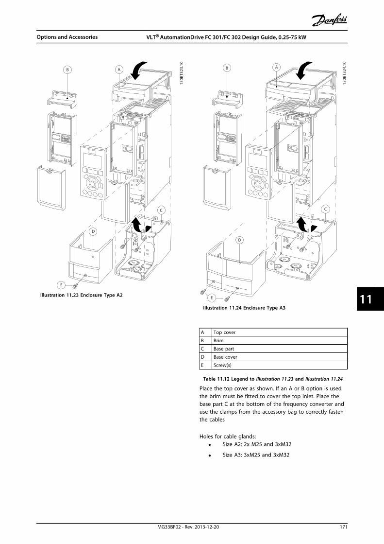
AB
C
D
E
130B
T323
.10
Illustration 11.23 Enclosure Type A2
B A
E
C
D
130B
T324
.10
Illustration 11.24 Enclosure Type A3
A Top cover
B Brim
C Base part
D Base cover
E Screw(s)
Table 11.12 Legend to Illustration 11.23 and Illustration 11.24
Place the top cover as shown. If an A or B option is usedthe brim must be fitted to cover the top inlet. Place thebase part C at the bottom of the frequency converter anduse the clamps from the accessory bag to correctly fastenthe cables
Holes for cable glands:
• Size A2: 2x M25 and 3xM32
• Size A3: 3xM25 and 3xM32
Options and Accessories VLT® AutomationDrive FC 301/FC 302 Design Guide, 0.25-75 kW
MG33BF02 - Rev. 2013-12-20 171
11 11

Enclosure typeHeight A
[mm]Width B
[mm]Depth C*
[mm]
A2 372 90 205
A3 372 130 205
B3 475 165 249
B4 670 255 246
C3 755 329 337
C4 950 391 337
Table 11.13 Dimensions
* If option A/B is used, the depth increases (see chapter 8.2.1 Mechanical Dimensions for details)
E
F
D
C
BA
130B
T620
.12
Illustration 11.25 Enclosure Type B3
130B
T621
.12
D
C
A
G
Illustration 11.26 Enclosure Types B4 - C3 - C4
A Top cover
B Brim
C Base part
D Base cover
E Screw(s)
F Fan cover
G Top clip
Table 11.14 Legend to Illustration 11.25 and Illustration 11.25
Options and Accessories VLT® AutomationDrive FC 301/FC 302 Design Guide, 0.25-75 kW
172 MG33BF02 - Rev. 2013-12-20
1111
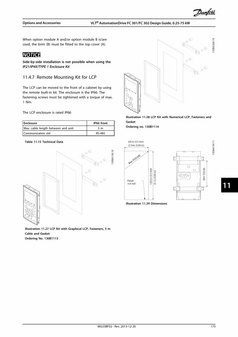
When option module A and/or option module B is/areused, the brim (B) must be fitted to the top cover (A).
NOTICESide-by-side installation is not possible when using theIP21/IP4X/TYPE 1 Enclosure Kit
11.4.7 Remote Mounting Kit for LCP
The LCP can be moved to the front of a cabinet by usingthe remote built-in kit. The enclosure is the IP66. Thefastening screws must be tightened with a torque of max.1 Nm.
The LCP enclosure is rated IP66
Enclosure IP66 front
Max. cable length between and unit 3 m
Communication std RS-485
Table 11.15 Technical Data
130B
A13
8.10
Illustration 11.27 LCP Kit with Graphical LCP, Fasteners, 3 mCable and GasketOrdering No. 130B1113
130B
A20
0.10
Illustration 11.28 LCP Kit with Numerical LCP, Fasteners andGasketOrdering no. 130B1114
Max R2(0.08)
Panelcut out
Min
72(
2.8)
130B
A13
9.11
129,
5± 0
.5 m
m
64,5± 0.5 mm(2.54± 0.04 in)
(5.1
± 0.
04 in
)
Illustration 11.29 Dimensions
Options and Accessories VLT® AutomationDrive FC 301/FC 302 Design Guide, 0.25-75 kW
MG33BF02 - Rev. 2013-12-20 173
11 11

11.4.8 Mounting Bracket for EnclosureTypes A5, B1, B2, C1 and C2
Step 1
130B
A84
4.10
Illustration 11.30 Lower Bracket
Position the lower bracket and mount it with screws. Donot tighten the screws completely since this will make itdifficult to mount the frequency converter.
Step 2
130B
A84
5.10
AB
Illustration 11.31 Upper Bracket
Measure distance A or B, and position the upper bracket,but do not tighten it. See dimensions in Table 11.16.
Enclosure IP A [mm] B [mm] Ordering number
A5 55/66 480 495 130B1080
B1 21/55/66 535 550 130B1081
B2 21/55/66 705 720 130B1082
B3 21/55/66 730 745 130B1083
B4 21/55/66 820 835 130B1084
Table 11.16 Details
Step 3
130B
A84
6.10
Illustration 11.32 Positioning
Options and Accessories VLT® AutomationDrive FC 301/FC 302 Design Guide, 0.25-75 kW
174 MG33BF02 - Rev. 2013-12-20
1111
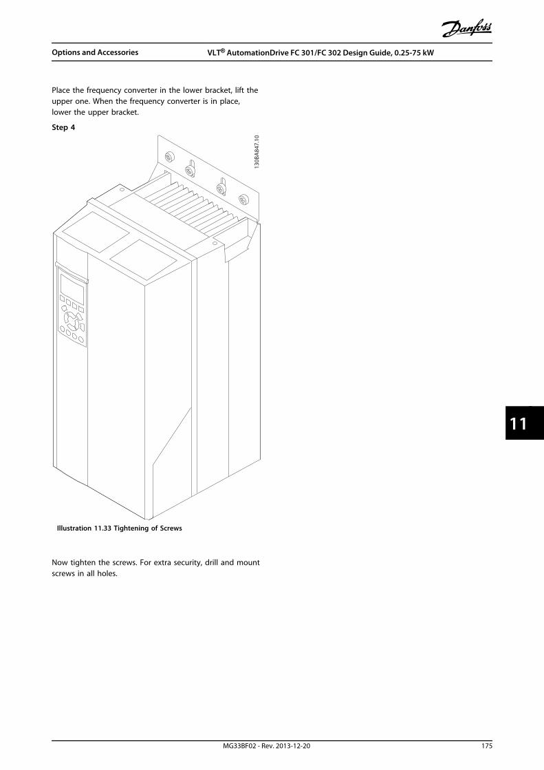
Place the frequency converter in the lower bracket, lift theupper one. When the frequency converter is in place,lower the upper bracket.
Step 4
130B
A84
7.10
Illustration 11.33 Tightening of Screws
Now tighten the screws. For extra security, drill and mountscrews in all holes.
Options and Accessories VLT® AutomationDrive FC 301/FC 302 Design Guide, 0.25-75 kW
MG33BF02 - Rev. 2013-12-20 175
11 11

12 RS-485 Installation and Set-up
12.1 Installation and Set-up
12.1.1 Overview
RS-485 is a 2-wire bus interface compatible with multi-drop network topology, that is, nodes can be connected as a bus, orvia drop cables from a common trunk line. A total of 32 nodes can be connected to one network segment.Repeaters divide network segments, see Illustration 12.1.
Illustration 12.1 RS-485 Bus Interface
NOTICEEach repeater functions as a node within the segment inwhich it is installed. Each node connected within a givennetwork must have a unique node address across allsegments.
Terminate each segment at both ends, using either thetermination switch (S801) of the frequency converters or abiased termination resistor network. Always use screenedtwisted pair (STP) cable for bus cabling, and follow goodcommon installation practice.
Low-impedance ground connection of the screen at everynode is important, including at high frequencies. Thus,connect a large surface of the screen to ground, forexample with a cable clamp or a conductive cable gland. Itmay be necessary to apply potential-equalising cables tomaintain the same earth potential throughout the network- particularly in installations with long cables.
To prevent impedance mismatch, always use the sametype of cable throughout the entire network. Whenconnecting a motor to the frequency converter, always usescreened motor cable.
Cable Screened twisted pair (STP)
Impedance [Ω] 120
Cable length[m]
Max. 1200 (including drop lines)Max. 500 station-to-station
Table 12.1 Cable Specifications
RS-485 Installation and Set... VLT® AutomationDrive FC 301/FC 302 Design Guide, 0.25-75 kW
176 MG33BF02 - Rev. 2013-12-20
1212

12.2 Network Connection
One or more frequency converters can be connected to acontrol (or master) using the RS-485 standardised interface.Terminal 68 is connected to the P signal (TX+, RX+), whileterminal 69 is connected to the N signal (TX-,RX-). Seedrawings in chapter 3.5 Wiring Schematic.
If more than one frequency converter is connected to amaster, use parallel connections.
130B
A06
0.11
68 69 68 69 68 69
RS 485
RS 232USB
+
-
Illustration 12.2 Parallel Connections
To avoid potential equalising currents in the screen,ground the cable screen via terminal 61, which isconnected to the frame via an RC-link.
130B
B021
.10
12 13 18 19 27 29 32 33 20 37
Remove jumper to enable Safe Stop
61 68 69 39 42 50 53 54 55
Illustration 12.3 Control Card Terminals
12.3 Bus Termination
The RS-485 bus must be terminated by a resistor networkat both ends. For this purpose, set switch S801 on thecontrol card for "ON".
Communication protocol must be set to 8-30 Protocol.
12.4 RS-485 Installation and Set-up
12.4.1 EMC Precautions
The following EMC precautions are recommended toachieve interference-free operation of the RS-485 network.
Observe relevant national and local regulations, forexample regarding protective earth connection. Keep theRS-485 communication cable away from motor and brakeresistor cables to avoid coupling of high frequency noisefrom one cable to another. Normally, a distance of 200 mm(8 inches) is sufficient, but keeping the greatest possibledistance between the cables is recommended, especiallywhere cables run in parallel over long distances. Whencrossing is unavoidable, the RS-485 cable must cross motorand brake resistor cables at an angle of 90°.
Fiel
dbus
cab
le
Min. 200 mm
90° crossing
Brake resistor
130B
D50
7.11
Illustration 12.4 Cable Routing
12.5 FC Protocol Overview
The FC protocol, also referred to as FC bus or Standardbus, is the Danfoss standard fieldbus. It defines an accesstechnique according to the master-follower principle forcommunications via a serial bus.One master and a maximum of 126 followers can beconnected to the bus. The master selects the individualfollowers via an address character in the telegram. Afollower itself can never transmit without first beingrequested to do so, and direct message transfer betweenthe individual followers is not possible. Communicationsoccur in the half-duplex mode.
RS-485 Installation and Set... VLT® AutomationDrive FC 301/FC 302 Design Guide, 0.25-75 kW
MG33BF02 - Rev. 2013-12-20 177
12 12
The master function cannot be transferred to another node(single-master system).
The physical layer is RS-485, thus utilising the RS-485 portbuilt into the frequency converter. The FC protocolsupports different telegram formats:
• A short format of 8 bytes for process data
• A long format of 16 bytes that also includes aparameter channel
• A format used for texts
12.6 Network Configuration
12.6.1 Frequency Converter Set-up
Set the following parameters to enable the FC protocol forthe frequency converter.
Parameter Number Setting
8-30 Protocol FC
8-31 Address 1-126
8-32 FC Port Baud Rate 2400-115200
8-33 Parity / Stop Bits Even parity, 1 stop bit (default)
Table 12.2 FC Protocol Parameters
12.7 FC Protocol Message FramingStructure
12.7.1 Content of a Character (byte)
Each character transferred begins with a start bit. Then 8data bits are transferred, corresponding to a byte. Eachcharacter is secured via a parity bit. This bit is set at "1"when it reaches parity. Parity is when there is an equalnumber of 1s in the 8 data bits and the parity bit in total.A stop bit completes a character, thus consisting of 11 bitsin all.
0 1 32 4 5 6 7
195N
A03
6.10
Startbit
Even StopParity bit
Illustration 12.5 Content of a Character
12.7.2 Telegram Structure
Each telegram has the following structure:
1. Start character (STX)=02 hex
2. A byte denoting the telegram length (LGE)
3. A byte denoting the frequency converter address(ADR)
A number of data bytes (variable, depending on the typeof telegram) follows.
A data control byte (BCC) completes the telegram.
STX LGE ADR DATA BCC
195N
A09
9.10
Illustration 12.6 Telegram Structure
12.7.3 Telegram Length (LGE)
The telegram length is the number of data bytes plus theaddress byte ADR and the data control byte BCC.
4 data bytes LGE=4+1+1=6 bytes
12 data bytes LGE=12+1+1=14 bytes
Telegramscontaining texts 101)+n bytes
Table 12.3 Length of Telegrams
1) The 10 represents the fixed characters, while the “n’” is variable(depending on the length of the text).
12.7.4 Frequency Converter Address (ADR)
2 different address formats are used.The address range of the frequency converter is either 1-31or 1-126.
1. Address format 1-31:
Bit 7 = 0 (address format 1-31 active)
Bit 6 is not used
Bit 5 = 1: Broadcast, address bits (0-4) are notused
Bit 5 = 0: No Broadcast
Bit 0-4 = frequency converter address 1-31
2. Address format 1-126:
Bit 7 = 1 (address format 1-126 active)
Bit 0-6 = frequency converter address 1-126
Bit 0-6 = 0 Broadcast
The follower returns the address byte unchanged to themaster in the response telegram.
12.7.5 Data Control Byte (BCC)
The checksum is calculated as an XOR-function. Before thefirst byte in the telegram is received, the CalculatedChecksum is 0.
RS-485 Installation and Set... VLT® AutomationDrive FC 301/FC 302 Design Guide, 0.25-75 kW
178 MG33BF02 - Rev. 2013-12-20
1212

12.7.6 The Data Field
The structure of data blocks depends on the type of telegram. There are 3 telegram types, and the type applies for bothcontrol telegrams (master⇒follower) and response telegrams (follower⇒master).
The 3 types of telegram are:
Process block (PCD)The PCD is made up of a data block of 4 bytes (2 words) and contains:
• Control word and reference value (from master to follower)
• Status word and present output frequency (from follower to master)
ADRLGESTX PCD1 PCD2 BCC
130B
A26
9.10
Illustration 12.7 Process Block
Parameter blockThe parameter block is used to transfer parameters between master and follower. The data block is made up of 12 bytes (6words) and also contains the process block.
PKE INDADRLGESTX PCD1 PCD2 BCC
130B
A27
1.10
PWEhigh PWElow
Illustration 12.8 Parameter Block
Text blockThe text block is used to read or write texts via the data block.
PKE IND
130B
A27
0.10
ADRLGESTX PCD1 PCD2 BCCCh1 Ch2 Chn
Illustration 12.9 Text Block
RS-485 Installation and Set... VLT® AutomationDrive FC 301/FC 302 Design Guide, 0.25-75 kW
MG33BF02 - Rev. 2013-12-20 179
12 12

12.7.7 The PKE Field
The PKE field contains 2 sub-fields: Parameter commandand response AK, and Parameter number PNU:
15 14 13 12 11 10 9 8 7 6 5 4 3 2 1 0
130B
A26
8.10
PKE IND PWEhigh PWElow
AK PNU
Para
met
er
com
man
ds
and
repl
ies
Para
met
ernu
mbe
r
Illustration 12.10 PKE Field
Bits no. 12-15 transfer parameter commands from masterto follower and return processed follower responses to themaster.
Bit no. Parameter command
15 14 13 12
0 0 0 0 No command
0 0 0 1 Read parameter value
0 0 1 0 Write parameter value in RAM (word)
0 0 1 1 Write parameter value in RAM (doubleword)
1 1 0 1 Write parameter value in RAM andEEprom (double word)
1 1 1 0 Write parameter value in RAM andEEprom (word)
1 1 1 1 Read/write text
Table 12.4 Parameter Commands Master ⇒ Follower
Bit no. Response
15 14 13 12
0 0 0 0 No response
0 0 0 1 Parameter value transferred (word)
0 0 1 0 Parameter value transferred (doubleword)
0 1 1 1 Command cannot be performed
1 1 1 1 text transferred
Table 12.5 Response Follower⇒ Master
If the command cannot be performed, the follower sendsthis response:0111 Command cannot be performed
- and issues the following fault report in the parametervalue (PWE):
PWE low(Hex)
Fault Report
0 The parameter number used does not exit
1 There is no write access to the defined parameter
2 Data value exceeds the parameter's limits
3 The sub index used does not exit
4 The parameter is not the array type
5 The data type does not match the definedparameter
11 Data change in the defined parameter is notpossible in the frequency converter's presentmode. Certain parameters can only be changedwhen the motor is turned off
82 There is no bus access to the defined parameter
83 Data change is not possible because factory set-up is selected
Table 12.6 Parameter Value Fault Report
12.7.8 Parameter Number (PNU)
Bits no. 0-11 transfer parameter numbers. The function ofthe relevant parameter is defined in the parameterdescription in the Programming Guide.
12.7.9 Index (IND)
The index is used together with the parameter number toread/write-access parameters with an index, e.g.15-30 Alarm Log: Error Code. The index consists of 2 bytes,a low byte and a high byte.
Only the low byte is used as an index.
12.7.10 Parameter Value (PWE)
The parameter value block consists of 2 words (4 bytes),and the value depends on the defined command (AK). Themaster prompts for a parameter value when the PWE blockcontains no value. To change a parameter value (write),write the new value in the PWE block and send from themaster to the follower.
When a follower responds to a parameter request (readcommand), the present parameter value in the PWE blockis transferred and returned to the master. If a parametercontains not a numerical value, but several data options,e.g. 0-01 Language where [0] is English, and [4] is Danish,select the data value by entering the value in the PWEblock. See Example - Selecting a data value. Serialcommunication is only capable of reading parameterscontaining data type 9 (text string).
RS-485 Installation and Set... VLT® AutomationDrive FC 301/FC 302 Design Guide, 0.25-75 kW
180 MG33BF02 - Rev. 2013-12-20
1212
15-40 FC Type to 15-53 Power Card Serial Number containdata type 9.For example, read the unit size and mains voltage range in15-40 FC Type. When a text string is transferred (read), thelength of the telegram is variable, and the texts are ofdifferent lengths. The telegram length is defined in thesecond byte of the telegram, LGE. When using text transferthe index character indicates whether it is a read or a writecommand.
To read a text via the PWE block, set the parametercommand (AK) to ’F’ Hex. The index character high-bytemust be “4”.
Some parameters contain text that can be written to viathe serial bus. To write a text via the PWE block, set theparameter command (AK) to ’F’ Hex. The index charactershigh-byte must be “5”.
PWE high PWE low
Read text
Write text
130B
A27
5.10PKE IND
Fx xx 04 00
Fx xx 05 00
Illustration 12.11 Text via PWE Block
12.7.11 Supported Data Types
Unsigned means that there is no operational sign in thetelegram.
Data types Description
3 Integer 16
4 Integer 32
5 Unsigned 8
6 Unsigned 16
7 Unsigned 32
9 Text string
10 Byte string
13 Time difference
33 Reserved
35 Bit sequence
Table 12.7 Supported Data Types
12.7.12 Conversion
The various attributes of each parameter are displayed infactory setting. Parameter values are transferred as wholenumbers only. Conversion factors are therefore used totransfer decimals.
4-12 Motor Speed Low Limit [Hz] has a conversion factor of0.1. To preset the minimum frequency to 10 Hz, transferthe value 100. A conversion factor of 0.1 means that the
value transferred is multiplied by 0.1. The value 100 istherefore read as 10.0.
Examples:0 s ⇒ conversion index 00.00 s ⇒ conversion index -20 ms ⇒ conversion index -30.00 ms ⇒ conversion index -5
Conversion index Conversion factor
100
75
74
67
6 1000000
5 100000
4 10000
3 1000
2 100
1 10
0 1
-1 0.1
-2 0.01
-3 0.001
-4 0.0001
-5 0.00001
-6 0.000001
-7 0.0000001
Table 12.8 Conversion Table
12.7.13 Process Words (PCD)
The block of process words is divided into 2 blocks of 16bits, which always occur in the defined sequence.
PCD 1 PCD 2
Control telegram (master⇒follower controlword)
Reference-value
Control telegram (follower⇒master) statusword
Present outputfrequency
Table 12.9 Process Words (PCD)
12.8 Examples
12.8.1 Writing a Parameter Value
Change 4-14 Motor Speed High Limit [Hz] to 100 Hz.Write the data in EEPROM.
PKE = E19E Hex - Write single word in 4-14 Motor SpeedHigh Limit [Hz]IND = 0000 HexPWEHIGH = 0000 Hex
RS-485 Installation and Set... VLT® AutomationDrive FC 301/FC 302 Design Guide, 0.25-75 kW
MG33BF02 - Rev. 2013-12-20 181
12 12

PWELOW = 03E8 Hex - Data value 1000, corresponding to100 Hz, see chapter 12.7.12 Conversion.
The telegram looks like this:
E19E H
PKE IND PWE high PWE low
0000 H 0000 H 03E8 H
130B
A09
2.10
Illustration 12.12 Write Data in EEPROM
NOTICE4-14 Motor Speed High Limit [Hz] is a single word, and theparameter command for write in EEPROM is “E”.Parameter number 4-14 is 19E in hexadecimal.
The response from the follower to the master is:
119E H
PKE IND PWE high PWE low
0000 H 0000 H 03E8 H
130B
A09
3.10
Illustration 12.13 Response from Follower
12.8.2 Reading a Parameter Value
Read the value in 3-41 Ramp 1 Ramp Up Time
PKE = 1155 Hex - Read parameter value in 3-41 Ramp 1Ramp Up TimeIND = 0000 HexPWEHIGH = 0000 HexPWELOW = 0000 Hex
1155 H
PKE IND PWE high PWE low
0000 H 0000 H 0000 H
130B
A09
4.10
Illustration 12.14 Parameter Value
If the value in 3-41 Ramp 1 Ramp Up Time is 10 s, theresponse from the follower to the master is
130B
A26
7.10
1155 H
PKE IND
0000 H 0000 H 03E8 H
PWE high PWE low
Illustration 12.15 Response from Follower
3E8 Hex corresponds to 1000 decimal. The conversionindex for 3-41 Ramp 1 Ramp Up Time is -2, i.e. 0.01.3-41 Ramp 1 Ramp Up Time is of the type Unsigned 32.
12.9 Modbus RTU Overview
12.9.1 Assumptions
Danfoss assumes that the installed controller supports theinterfaces in this document, and strictly observes allrequirements and limitations stipulated in the controllerand frequency converter.
12.9.2 What the User Should Already Know
The built-in Modbus RTU (Remote Terminal Unit) isdesigned to communicate with any controller thatsupports the interfaces defined in this document. It isassumed that the user has full knowledge of thecapabilities and limitations of the controller.
12.9.3 Modbus RTU Overview
Regardless of the type of physical communicationnetworks, the Modbus RTU Overview describes the processa controller uses to request access to another device. Thisprocess includes how the Modbus RTU responds torequests from another device, and how errors are detectedand reported. It also establishes a common format for thelayout and contents of message fields.During communications over a Modbus RTU network, theprotocol determines:
• How each controller learns its device address
• Recognises a message addressed to it
• Determines which actions to take
• Extracts any data or other information containedin the message
If a reply is required, the controller constructs the replymessage and sends it.Controllers communicate using a master-followertechnique in which only the master can initiatetransactions (called queries). Followers respond bysupplying the requested data to the master, or by takingthe action requested in the query.The master can address individual followers, or initiate abroadcast message to all followers. Followers return aresponse to queries that are addressed to themindividually. No responses are returned to broadcastqueries from the master. The Modbus RTU protocolestablishes the format for the master’s query by providingthe device (or broadcast) address, a function code definingthe requested action, any data to be sent, and an error-checking field. The follower’s response message is alsoconstructed using Modbus protocol. It contains fieldsconfirming the action taken, any data to be returned, andan error-checking field. If an error occurs in receipt of themessage, or if the follower is unable to perform the
RS-485 Installation and Set... VLT® AutomationDrive FC 301/FC 302 Design Guide, 0.25-75 kW
182 MG33BF02 - Rev. 2013-12-20
1212

requested action, the follower constructs an error message,and send it in response, or a time-out occurs.
12.9.4 Frequency Converter with ModbusRTU
The frequency converter communicates in Modbus RTUformat over the built-in RS-485 interface. Modbus RTUprovides access to the control word and bus reference ofthe frequency converter.
The control word allows the modbus master to controlseveral important functions of the frequency converter:
• Start
• Stop of the frequency converter in various ways:
- Coast stop
- Quick stop
- DC Brake stop
- Normal (ramp) stop
• Reset after a fault trip
• Run at a variety of preset speeds
• Run in reverse
• Change the active set-up
• Control the frequency converter’s built-in relay
The bus reference is commonly used for speed control. It isalso possible to access the parameters, read their values,and where possible, write values to them. This permits arange of control options, including controlling the setpointof the frequency converter when its internal PI controller isused.
12.10 Network Configuration
To enable Modbus RTU on the frequency converter, set thefollowing parameters
Parameter Setting
8-30 Protocol Modbus RTU
8-31 Address 1-247
8-32 Baud Rate 2400-115200
8-33 Parity / Stop Bits Even parity, 1 stop bit (default)
Table 12.10 Modbus RTU Parameters
12.11 Modbus RTU Message FramingStructure
12.11.1 Frequency Converter with ModbusRTU
The controllers are set up to communicate on the Modbusnetwork using RTU (Remote Terminal Unit) mode, witheach byte in a message containing 2 4-bit hexadecimalcharacters. The format for each byte is shown inTable 12.11.
Startbit
Data byte Stop/parity
Stop
Table 12.11 Format for Each Byte
Coding System 8-bit binary, hexadecimal 0-9, A-F. 2hexadecimal characters contained in each 8-bit field of the message
Bits Per Byte 1 start bit8 data bits, least significant bit sent first1 bit for even/odd parity; no bit for noparity1 stop bit if parity is used; 2 bits if no parity
Error Check Field Cyclical Redundancy Check (CRC)
12.11.2 Modbus RTU Message Structure
The transmitting device places a Modbus RTU messageinto a frame with a known beginning and ending point.This allows receiving devices to begin at the start of themessage, read the address portion, determine whichdevice is addressed (or all devices, if the message isbroadcast), and to recognise when the message iscompleted. Partial messages are detected and errors set asa result. Characters for transmission must be inhexadecimal 00 to FF format in each field. The frequencyconverter continuously monitors the network bus, alsoduring ‘silent’ intervals. When the first field (the addressfield) is received, each frequency converter or devicedecodes it to determine which device is being addressed.Modbus RTU messages addressed to zero are broadcastmessages. No response is permitted for broadcastmessages. A typical message frame is shown in Table 12.12.
Start Address Function Data CRCcheck
End
T1-T2-T3-T4
8 bits 8 bits N x 8bits
16 bits T1-T2-T3-T4
Table 12.12 Typical Modbus RTU Message Structure
RS-485 Installation and Set... VLT® AutomationDrive FC 301/FC 302 Design Guide, 0.25-75 kW
MG33BF02 - Rev. 2013-12-20 183
12 12
12.11.3 Start/Stop Field
Messages start with a silent period of at least 3.5 characterintervals. This is implemented as a multiple of characterintervals at the selected network baud rate (shown as StartT1-T2-T3-T4). The first field to be transmitted is the deviceaddress. Following the last transmitted character, a similarperiod of at least 3.5 character intervals marks the end ofthe message. A new message can begin after this period.The entire message frame must be transmitted as acontinuous stream. If a silent period of more than 1.5character intervals occurs before completion of the frame,the receiving device flushes the incomplete message andassumes that the next byte is the address field of a newmessage. Similarly, if a new message begins before 3.5character intervals after a previous message, the receivingdevice considers it a continuation of the previous message.This causes a time-out (no response from the follower),since the value in the final CRC field is not valid for thecombined messages.
12.11.4 Address Field
The address field of a message frame contains 8 bits. Validfollower device addresses are in the range of 0-247decimal. The individual follower devices are assignedaddresses in the range of 1-247. (0 is reserved forbroadcast mode, which all followers recognise.) A masteraddresses a follower by placing the follower address in theaddress field of the message. When the follower sends itsresponse, it places its own address in this address field tolet the master know which follower is responding.
12.11.5 Function Field
The function field of a message frame contains 8 bits. Validcodes are in the range of 1-FF. Function fields are used tosend messages between master and follower. When amessage is sent from a master to a follower device, thefunction code field tells the follower what kind of action toperform. When the follower responds to the master, it usesthe function code field to indicate either a normal (error-free) response, or that some kind of error occurred (calledan exception response). For a normal response, thefollower simply echoes the original function code. For anexception response, the follower returns a code that isequivalent to the original function code with its mostsignificant bit set to logic 1. In addition, the follower placesa unique code into the data field of the response message.This tells the master what kind of error occurred, or thereason for the exception. Also refer tochapter 12.11.10 Function Codes Supported by Modbus RTUand chapter 12.11.11 Modbus Exception Codes
12.11.6 Data Field
The data field is constructed using sets of 2 hexadecimaldigits, in the range of 00 to FF hexadecimal. These aremade up of one RTU character. The data field of messagessent from a master to follower device contains additionalinformation which the follower must use to take the actiondefined by the function code. This can include items suchas coil or register addresses, the quantity of items to behandled, and the count of actual data bytes in the field.
12.11.7 CRC Check Field
Messages include an error-checking field, operating basedon a Cyclical Redundancy Check (CRC) method. The CRCfield checks the contents of the entire message. It isapplied regardless of any parity check method used for theindividual characters of the message. The CRC value iscalculated by the transmitting device, which appends theCRC as the last field in the message. The receiving devicerecalculates a CRC during receipt of the message andcompares the calculated value to the actual value receivedin the CRC field. If the 2 values are unequal, a bus time-outresults. The error-checking field contains a 16-bit binaryvalue implemented as 2 8-bit bytes. When this is done, thelow-order byte of the field is appended first, followed bythe high-order byte. The CRC high-order byte is the lastbyte sent in the message.
12.11.8 Coil Register Addressing
In Modbus, all data are organised in coils and holdingregisters. Coils hold a single bit, whereas holding registershold a 2-byte word (i.e. 16 bits). All data addresses inModbus messages are referenced to zero. The firstoccurrence of a data item is addressed as item numberzero. For example: The coil known as ‘coil 1’ in aprogrammable controller is addressed as coil 0000 in thedata address field of a Modbus message. Coil 127 decimalis addressed as coil 007EHEX (126 decimal).Holding register 40001 is addressed as register 0000 in thedata address field of the message. The function code fieldalready specifies a ‘holding register’ operation. Therefore,the ‘4XXXX’ reference is implicit. Holding register 40108 isaddressed as register 006BHEX (107 decimal).
RS-485 Installation and Set... VLT® AutomationDrive FC 301/FC 302 Design Guide, 0.25-75 kW
184 MG33BF02 - Rev. 2013-12-20
1212
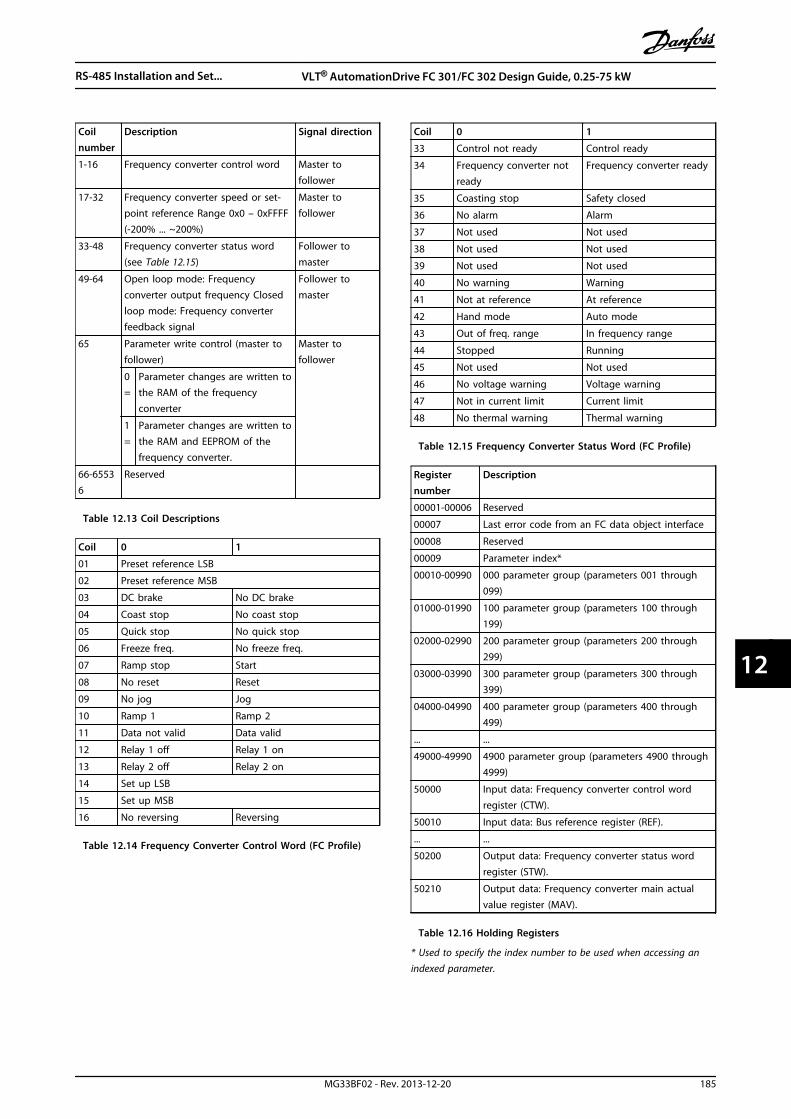
Coilnumber
Description Signal direction
1-16 Frequency converter control word Master tofollower
17-32 Frequency converter speed or set-point reference Range 0x0 – 0xFFFF(-200% ... ~200%)
Master tofollower
33-48 Frequency converter status word(see Table 12.15)
Follower tomaster
49-64 Open loop mode: Frequencyconverter output frequency Closedloop mode: Frequency converterfeedback signal
Follower tomaster
65 Parameter write control (master tofollower)
Master tofollower
0=
Parameter changes are written tothe RAM of the frequencyconverter
1=
Parameter changes are written tothe RAM and EEPROM of thefrequency converter.
66-65536
Reserved
Table 12.13 Coil Descriptions
Coil 0 1
01 Preset reference LSB
02 Preset reference MSB
03 DC brake No DC brake
04 Coast stop No coast stop
05 Quick stop No quick stop
06 Freeze freq. No freeze freq.
07 Ramp stop Start
08 No reset Reset
09 No jog Jog
10 Ramp 1 Ramp 2
11 Data not valid Data valid
12 Relay 1 off Relay 1 on
13 Relay 2 off Relay 2 on
14 Set up LSB
15 Set up MSB
16 No reversing Reversing
Table 12.14 Frequency Converter Control Word (FC Profile)
Coil 0 1
33 Control not ready Control ready
34 Frequency converter notready
Frequency converter ready
35 Coasting stop Safety closed
36 No alarm Alarm
37 Not used Not used
38 Not used Not used
39 Not used Not used
40 No warning Warning
41 Not at reference At reference
42 Hand mode Auto mode
43 Out of freq. range In frequency range
44 Stopped Running
45 Not used Not used
46 No voltage warning Voltage warning
47 Not in current limit Current limit
48 No thermal warning Thermal warning
Table 12.15 Frequency Converter Status Word (FC Profile)
Registernumber
Description
00001-00006 Reserved
00007 Last error code from an FC data object interface
00008 Reserved
00009 Parameter index*
00010-00990 000 parameter group (parameters 001 through099)
01000-01990 100 parameter group (parameters 100 through199)
02000-02990 200 parameter group (parameters 200 through299)
03000-03990 300 parameter group (parameters 300 through399)
04000-04990 400 parameter group (parameters 400 through499)
... ...
49000-49990 4900 parameter group (parameters 4900 through4999)
50000 Input data: Frequency converter control wordregister (CTW).
50010 Input data: Bus reference register (REF).
... ...
50200 Output data: Frequency converter status wordregister (STW).
50210 Output data: Frequency converter main actualvalue register (MAV).
Table 12.16 Holding Registers
* Used to specify the index number to be used when accessing anindexed parameter.
RS-485 Installation and Set... VLT® AutomationDrive FC 301/FC 302 Design Guide, 0.25-75 kW
MG33BF02 - Rev. 2013-12-20 185
12 12

12.11.9 How to Control the FrequencyConverter
This section describes codes which can be used in thefunction and data fields of a Modbus RTU message.
12.11.10 Function Codes Supported byModbus RTU
Modbus RTU supports use of the following function codesin the function field of a message.
Function Function code (hex)
Read coils 1
Read holding registers 3
Write single coil 5
Write single register 6
Write multiple coils F
Write multiple registers 10
Get comm. event counter B
Report follower ID 11
Table 12.17 Function Codes
Function FunctionCode
Sub-functioncode
Sub-function
Diagnostics 8 1 Restart communication
2 Return diagnostic register
10 Clear counters anddiagnostic register
11 Return bus message count
12 Return bus communi-cation error count
13 Return follower errorcount
14 Return follower messagecount
Table 12.18 Function Codes
12.11.11 Modbus Exception Codes
For a full explanation of the structure of an exception coderesponse, refer to chapter 12.11.5 Function Field.
Code Name Meaning1 Illegal
functionThe function code received in the query isnot an allowable action for the server (orfollower). This may be because thefunction code is only applicable to newerdevices, and was not implemented in theunit selected. It could also indicate thatthe server (or follower) is in the wrongstate to process a request of this type, forexample because it is not configured andis being asked to return register values.
2 Illegal dataaddress
The data address received in the query isnot an allowable address for the server(or follower). More specifically, thecombination of reference number andtransfer length is invalid. For a controllerwith 100 registers, a request with offset96 and length 4 would succeed, a requestwith offset 96 and length 5 generatesexception 02.
3 Illegal datavalue
A value contained in the query data fieldis not an allowable value for server (orfollower). This indicates a fault in thestructure of the remainder of a complexrequest, such as that the implied length isincorrect. It specifically does NOT meanthat a data item submitted for storage ina register has a value outside theexpectation of the application program,since the Modbus protocol is unaware ofthe significance of any particular value ofany particular register.
4 Followerdevice failure
An unrecoverable error occurred while theserver (or follower) was attempting toperform the requested action.
Table 12.19 Modbus Exception Codes
12.12 How to Access Parameters
12.12.1 Parameter Handling
The PNU (Parameter Number) is translated from theregister address contained in the Modbus read or writemessage. The parameter number is translated to Modbusas (10 x parameter number) DECIMAL. Example: Reading3-12 Catch up/slow Down Value (16bit): The holding register3120 holds the parameters value. A value of 1352(Decimal), means that the parameter is set to 12.52%
Reading 3-14 Preset Relative Reference (32bit): The holdingregisters 3410 & 3411 holds the parameters value. A valueof 11300 (Decimal), means that the parameter is set to1113.00.
For information on the parameters, size and convertingindex, consult the product relevant programming guide.
RS-485 Installation and Set... VLT® AutomationDrive FC 301/FC 302 Design Guide, 0.25-75 kW
186 MG33BF02 - Rev. 2013-12-20
1212
12.12.2 Storage of Data
The coil 65 decimal determines whether data written tothe frequency converter are stored in EEPROM and RAM(coil 65=1) or only in RAM (coil 65= 0).
12.12.3 IND (Index)
Some parameters in the frequency converter are arrayparameters e.g. 3-10 Preset Reference. Since the Modbusdoes not support arrays in the holding registers, thefrequency converter has reserved the holding register 9 aspointer to the array. Before reading or writing an arrayparameter, set the holding register 9. Setting holdingregister to the value of 2 causes all following read/write toarray parameters to be to the index 2.
12.12.4 Text Blocks
Parameters stored as text strings are accessed in the sameway as the other parameters. The maximum text block sizeis 20 characters. If a read request for a parameter is formore characters than the parameter stores, the response istruncated. If the read request for a parameter is for fewercharacters than the parameter stores, the response is spacefilled.
12.12.5 Conversion Factor
The different attributes for each parameter can be seen inthe section on factory settings. Since a parameter valuecan only be transferred as a whole number, a conversionfactor must be used to transfer decimals.
12.12.6 Parameter Values
Standard data typesStandard data types are int 16, int 32, uint 8, uint 16 anduint 32. They are stored as 4x registers (40001–4FFFF). Theparameters are read using function 03hex "Read HoldingRegisters." Parameters are written using the function 6hex"Preset Single Register" for 1 register (16 bits), and thefunction 10 hex "Preset Multiple Registers" for 2 registers(32 bits). Readable sizes range from 1 register (16 bits) upto 10 registers (20 characters).
Non-standard data typesNon-standard data types are text strings and are stored as4x registers (40001–4FFFF). The parameters are read usingfunction 03hex "Read Holding Registers" and written usingfunction 10hex "Preset Multiple Registers." Readable sizesrange from 1 register (2 characters) up to 10 registers (20characters).
12.13 Danfoss FC Control Profile
12.13.1 Control Word According to FCProfile (8-10 Control Profile = FCprofile)
Speed ref.CTW
Master-follower
130B
A27
4.11
15 14 13 12 11 10 9 8 7 6 5 4 3 2 1 0Bitno.:
Illustration 12.16 Control Word
Bit Bit value = 0 Bit value = 1
00 Reference value External selection lsb
01 Reference value External selection msb
02 DC brake Ramp
03 Coasting No coasting
04 Quick stop Ramp
05 Hold output frequency Use ramp
06 Ramp stop Start
07 No function Reset
08 No function Jog
09 Ramp 1 Ramp 2
10 Data invalid Data valid
11 No function Relay 01 active
12 No function Relay 02 active
13 Parameter set-up Selection lsb
14 Parameter set-up Selection msb
15 No function Reverse
Table 12.20 Control Word Bits
Explanation of the Control Bits
Bits 00/01Bits 00 and 01 are used to select between the 4 referencevalues, which are pre-programmed in 3-10 Preset Referenceaccording to Table 12.21.
Programmed ref.value
Parameter Bit 01 Bit 00
1 3-10 PresetReference [0]
0 0
2 3-10 PresetReference [1]
0 1
3 3-10 PresetReference [2]
1 0
4 3-10 PresetReference [3]
1 1
Table 12.21 Reference Values
RS-485 Installation and Set... VLT® AutomationDrive FC 301/FC 302 Design Guide, 0.25-75 kW
MG33BF02 - Rev. 2013-12-20 187
12 12

NOTICEMake a selection in 8-56 Preset Reference Select to definehow Bit 00/01 gates with the corresponding function onthe digital inputs.
Bit 02, DC brakeBit 02 = ’0’ leads to DC braking and stop. Set brakingcurrent and duration in 2-01 DC Brake Current and 2-02 DCBraking Time.Bit 02 = ’1’ leads to ramping.
Bit 03, CoastingBit 03 = ’0’: The frequency converter immediately "lets go"of the motor, (the output transistors are "shut off") and itcoasts to a standstill.Bit 03 = ’1’: The frequency converter starts the motor, ifthe other starting conditions are met.
Make a selection in 8-50 Coasting Select to define how Bit03 gates with the corresponding function on a digitalinput.
Bit 04, Quick stopBit 04 = ’0’: Makes the motor speed ramp down to stop(set in 3-81 Quick Stop Ramp Time).
Bit 05, Hold output frequencyBit 05 = ’0’: The present output frequency (in Hz) freezes.Change the frozen output frequency only with the digitalinputs (5-10 Terminal 18 Digital Input to 5-15 Terminal 33Digital Input) programmed to Speed up and Slow down.
NOTICEIf Freeze output is active, the frequency converter canonly be stopped by the following:
• Bit 03 Coasting stop
• Bit 02 DC braking
• Digital input (5-10 Terminal 18 Digital Input to5-15 Terminal 33 Digital Input) programmed toDC braking, Coasting stop, or Reset and coastingstop.
Bit 06, Ramp stop/startBit 06 = ’0’: Causes a stop and makes the motor speedramp down to stop via the selected ramp down parameter.Bit 06 = ’1’: Permits the frequency converter to start themotor, if the other starting conditions are met.
Make a selection in 8-53 Start Select to define how Bit 06Ramp stop/start gates with the corresponding function ona digital input.
Bit 07, ResetBit 07 = ’0’: No reset. Bit 07 = ’1’: Resets a trip. Reset isactivated on the signal’s leading edge, i.e. when changingfrom logic ’0’ to logic ’1’.
Bit 08, JogBit 08 = ’1’: The output frequency is determined by3-19 Jog Speed [RPM].
Bit 09, Selection of ramp 1/2Bit 09 = "0": Ramp 1 is active (3-41 Ramp 1 Ramp Up Timeto 3-42 Ramp 1 Ramp Down Time). Bit 09 = "1": Ramp 2(3-51 Ramp 2 Ramp Up Time to 3-52 Ramp 2 Ramp DownTime) is active.
Bit 10, Data not valid/Data validTells the frequency converter whether to use or ignore thecontrol word.Bit 10 = ’0’: The control word is ignored. Bit 10 = ’1’: Thecontrol word is used. This function is relevant because thetelegram always contains the control word, regardless ofthe telegram type. Turn off the control word, if it shouldnot be used when updating or reading parameters.
Bit 11, Relay 01Bit 11 = "0": Relay not activated.Bit 11 = "1": Relay 01 activated provided that Control wordbit 11 is selected in 5-40 Function Relay.
Bit 12, Relay 04Bit 12 = "0": Relay 04 is not activated.Bit 12 = "1": Relay 04 is activated provided that Controlword bit 12 is selected in 5-40 Function Relay.
Bit 13/14, Selection of set-upUse bits 13 and 14 to select from the 4 menu set-upsaccording to Table 12.22.
Set-up Bit 14 Bit 13
1 0 0
2 0 1
3 1 0
4 1 1
Table 12.22 4 Menu Set-ups
The function is only possible when Multi Set-Ups is selectedin 0-10 Active Set-up.
Make a selection in 8-55 Set-up Select to define how Bit13/14 gates with the corresponding function on the digitalinputs.
Bit 15 ReverseBit 15 = ’0’: No reversing.Bit 15 = ’1’: Reversing. In the default setting, reversing isset to digital in 8-54 Reversing Select. Bit 15 causesreversing only when Ser. communication, Logic or or Logicand is selected.
RS-485 Installation and Set... VLT® AutomationDrive FC 301/FC 302 Design Guide, 0.25-75 kW
188 MG33BF02 - Rev. 2013-12-20
1212

12.13.2 Status Word According to FCProfile (STW) (8-10 Control Profile =FC profile)
Output freq.STW
Bitno.:
Follower-master
15 14 13 12 11 10 9 8 7 6 5 4 3 2 1 0
130B
A27
3.11
Illustration 12.17 Status Word
Bit Bit = 0 Bit = 1
00 Control not ready Control ready
01 Drive not ready Drive ready
02 Coasting Enable
03 No error Trip
04 No error Error (no trip)
05 Reserved -
06 No error Triplock
07 No warning Warning
08 Speed ≠ reference Speed = reference
09 Local operation Bus control
10 Out of frequency limit Frequency limit OK
11 No operation In operation
12 Drive OK Stopped, auto start
13 Voltage OK Voltage exceeded
14 Torque OK Torque exceeded
15 Timer OK Timer exceeded
Table 12.23 Status Word Bits
Explanation of the Status Bits
Bit 00, Control not ready/readyBit 00 = ’0’: The frequency converter trips.Bit 00 = ’1’: The frequency converter controls are ready butthe power component does not necessarily receive anypower supply (in case of external 24 V supply to controls).
Bit 01, Drive readyBit 01 = ’1’: The frequency converter is ready for operationbut the coasting command is active via the digital inputsor via serial communication.
Bit 02, Coasting stopBit 02 = ’0’: The frequency converter releases the motor.Bit 02 = ’1’: The frequency converter starts the motor witha start command.
Bit 03, No error/tripBit 03 = ’0’ : The frequency converter is not in fault mode.Bit 03 = ’1’: The frequency converter trips. To re-establishoperation, enter [Reset].
Bit 04, No error/error (no trip)Bit 04 = ’0’: The frequency converter is not in fault mode.Bit 04 = “1”: The frequency converter shows an error butdoes not trip.
Bit 05, Not usedBit 05 is not used in the status word.
Bit 06, No error/triplockBit 06 = ’0’: The frequency converter is not in fault mode.Bit 06 = “1”: The frequency converter is tripped and locked.
Bit 07, No warning/warningBit 07 = ’0’: There are no warnings. Bit 07 = ’1’: A warninghas occurred.
Bit 08, Speed≠ reference/speed = referenceBit 08 = ’0’: The motor is running, but the present speed isdifferent from the preset speed reference. It might e.g. bethe case when the speed ramps up/down during start/stop.Bit 08 = ’1’: The motor speed matches the preset speedreference.
Bit 09, Local operation/bus controlBit 09 = ’0’: [STOP/RESET] is activated on the control unitor Local control in 3-13 Reference Site is selected. Controlvia serial communication is not possible.Bit 09 = ’1’ It is possible to control the frequency convertervia the fieldbus/serial communication.
Bit 10, Out of frequency limitBit 10 = ’0’: The output frequency has reached the value in4-11 Motor Speed Low Limit [RPM] or 4-13 Motor Speed HighLimit [RPM].Bit 10 = "1": The output frequency is within the definedlimits.
Bit 11, No operation/in operationBit 11 = ’0’: The motor is not running.Bit 11 = ’1’: The frequency converter has a start signal orthe output frequency is greater than 0 Hz.
Bit 12, Drive OK/stopped, autostartBit 12 = ’0’: There is no temporary overtemperature on theinverter.Bit 12 = ’1’: The inverter stops because of overtemperature,but the unit does not trip and resumes operation once theovertemperature stops.
Bit 13, Voltage OK/limit exceededBit 13 = ’0’: There are no voltage warnings.Bit 13 = ’1’: The DC-voltage in the frequency converter’sintermediate circuit is too low or too high.
Bit 14, Torque OK/limit exceededBit 14 = ’0’: The motor current is lower than the torquelimit selected in 4-18 Current Limit.Bit 14 = ’1’: The torque limit in 4-18 Current Limit isexceeded.
Bit 15, Timer OK/limit exceededBit 15 = ’0’: The timers for motor thermal protection andthermal protection are not exceeded 100%.Bit 15 = ’1’: One of the timers exceeds 100%.
RS-485 Installation and Set... VLT® AutomationDrive FC 301/FC 302 Design Guide, 0.25-75 kW
MG33BF02 - Rev. 2013-12-20 189
12 12
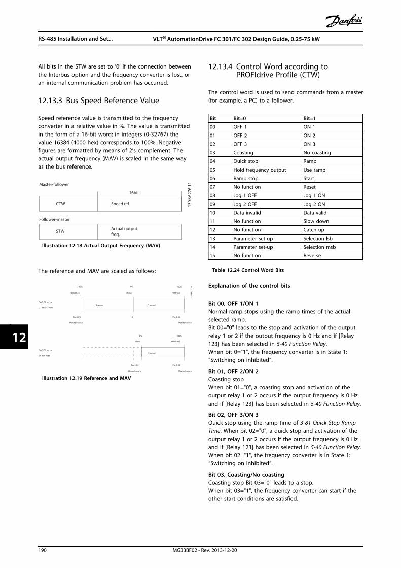
All bits in the STW are set to ’0’ if the connection betweenthe Interbus option and the frequency converter is lost, oran internal communication problem has occurred.
12.13.3 Bus Speed Reference Value
Speed reference value is transmitted to the frequencyconverter in a relative value in %. The value is transmittedin the form of a 16-bit word; in integers (0-32767) thevalue 16384 (4000 hex) corresponds to 100%. Negativefigures are formatted by means of 2’s complement. Theactual output frequency (MAV) is scaled in the same wayas the bus reference.
Actual outputfreq.
STW
Follower-master
Speed ref.CTW
Master-follower
16bit13
0BA
276.
11
Illustration 12.18 Actual Output Frequency (MAV)
The reference and MAV are scaled as follows:
Reverse ForwardPar.3-00 set to
(1) -max- +max
Max reference Max reference
Par.3-00 set to
(0) min-max
Max reference
Forward
Min reference
100%
(4000hex)
-100%
(C000hex)
0%
(0hex)
Par.3-03 0 Par.3-03
Par.3-03
(4000hex)(0hex)
0% 100%
Par.3-02
130B
A27
7.10
Illustration 12.19 Reference and MAV
12.13.4 Control Word according toPROFIdrive Profile (CTW)
The control word is used to send commands from a master(for example, a PC) to a follower.
Bit Bit=0 Bit=1
00 OFF 1 ON 1
01 OFF 2 ON 2
02 OFF 3 ON 3
03 Coasting No coasting
04 Quick stop Ramp
05 Hold frequency output Use ramp
06 Ramp stop Start
07 No function Reset
08 Jog 1 OFF Jog 1 ON
09 Jog 2 OFF Jog 2 ON
10 Data invalid Data valid
11 No function Slow down
12 No function Catch up
13 Parameter set-up Selection lsb
14 Parameter set-up Selection msb
15 No function Reverse
Table 12.24 Control Word Bits
Explanation of the control bits
Bit 00, OFF 1/ON 1Normal ramp stops using the ramp times of the actualselected ramp.Bit 00="0" leads to the stop and activation of the outputrelay 1 or 2 if the output frequency is 0 Hz and if [Relay123] has been selected in 5-40 Function Relay.When bit 0="1", the frequency converter is in State 1:“Switching on inhibited”.
Bit 01, OFF 2/ON 2Coasting stopWhen bit 01="0", a coasting stop and activation of theoutput relay 1 or 2 occurs if the output frequency is 0 Hzand if [Relay 123] has been selected in 5-40 Function Relay.
Bit 02, OFF 3/ON 3Quick stop using the ramp time of 3-81 Quick Stop RampTime. When bit 02="0", a quick stop and activation of theoutput relay 1 or 2 occurs if the output frequency is 0 Hzand if [Relay 123] has been selected in 5-40 Function Relay.When bit 02="1", the frequency converter is in State 1:“Switching on inhibited”.
Bit 03, Coasting/No coastingCoasting stop Bit 03="0" leads to a stop.When bit 03="1", the frequency converter can start if theother start conditions are satisfied.
RS-485 Installation and Set... VLT® AutomationDrive FC 301/FC 302 Design Guide, 0.25-75 kW
190 MG33BF02 - Rev. 2013-12-20
1212
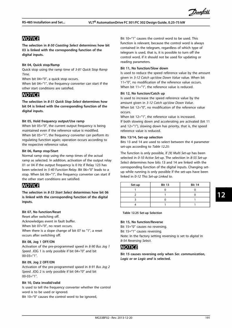
NOTICEThe selection in 8-50 Coasting Select determines how bit03 is linked with the corresponding function of thedigital inputs.
Bit 04, Quick stop/RampQuick stop using the ramp time of 3-81 Quick Stop RampTime.When bit 04="0", a quick stop occurs.When bit 04="1", the frequency converter can start if theother start conditions are satisfied.
NOTICEThe selection in 8-51 Quick Stop Select determines howbit 04 is linked with the corresponding function of thedigital inputs.
Bit 05, Hold frequency output/Use rampWhen bit 05="0", the current output frequency is beingmaintained even if the reference value is modified.When bit 05="1", the frequency converter can perform itsregulating function again; operation occurs according tothe respective reference value.
Bit 06, Ramp stop/StartNormal ramp stop using the ramp times of the actualramp as selected. In addition, activation of the output relay01 or 04 if the output frequency is 0 Hz if Relay 123 hasbeen selected in 5-40 Function Relay. Bit 06="0" leads to astop. When bit 06="1", the frequency converter can start ifthe other start conditions are satisfied.
NOTICEThe selection in 8-53 Start Select determines how bit 06is linked with the corresponding function of the digitalinputs.
Bit 07, No function/ResetReset after switching off.Acknowledges event in fault buffer.When bit 07="0", no reset occurs.When there is a slope change of bit 07 to "1", a resetoccurs after switching off.
Bit 08, Jog 1 OFF/ONActivation of the pre-programmed speed in 8-90 Bus Jog 1Speed. JOG 1 is only possible if bit 04="0" and bit00-03="1".
Bit 09, Jog 2 OFF/ONActivation of the pre-programmed speed in 8-91 Bus Jog 2Speed. JOG 2 is only possible if bit 04="0" and bit00-03="1".
Bit 10, Data invalid/validIs used to tell the frequency converter whether the controlword is to be used or ignored.Bit 10=“0” causes the control word to be ignored,
Bit 10=“1” causes the control word to be used. Thisfunction is relevant, because the control word is alwayscontained in the telegram, regardless of which type oftelegram is used, that is, it is possible to turn off thecontrol word, if it should not be used for updating orreading parameters.
Bit 11, No function/Slow downIs used to reduce the speed reference value by the amountgiven in 3-12 Catch up/slow Down Value value. When bit11="0", no modification of the reference value occurs.When bit 11="1", the reference value is reduced.
Bit 12, No function/Catch upIs used to increase the speed reference value by theamount given in 3-12 Catch up/slow Down Value.When bit 12="0", no modification of the reference valueoccurs.When bit 12="1", the reference value is increased.If both slowing down and accelerating are activated (bit 11and 12="1"), slowing down has priority, that is, the speedreference value is reduced.
Bits 13/14, Set-up selectionBits 13 and 14 are used to select between the 4 parameterset-ups according to Table 12.25:
The function is only possible, if [9] Multi Set-up has beenselected in 0-10 Active Set-up. The selection in 8-55 Set-upSelect determines how bits 13 and 14 are linked with thecorresponding function of the digital inputs. Changing set-up while running is only possible if the set-ups have beenlinked in 0-12 This Set-up Linked to.
Set-up Bit 13 Bit 14
1 0 0
2 1 0
3 0 1
4 1 1
Table 12.25 Set-up Selection
Bit 15, No function/ReverseBit 15=“0” causes no reversing.Bit 15=“1” causes reversing.Note: In the factory setting reversing is set to digital in8-54 Reversing Select.
NOTICEBit 15 causes reversing only when Ser. communication,Logic or or Logic and is selected.
RS-485 Installation and Set... VLT® AutomationDrive FC 301/FC 302 Design Guide, 0.25-75 kW
MG33BF02 - Rev. 2013-12-20 191
12 12

12.13.5 Status Word according toPROFIdrive Profile (STW)
The status word is used to notify a master (for example, aPC) about the status of a follower.
Bit Bit=0 Bit=1
00 Control not ready Control ready
01 Drive not ready Drive ready
02 Coasting Enable
03 No error Trip
04 OFF 2 ON 2
05 OFF 3 ON 3
06 Start possible Start not possible
07 No warning Warning
08 Speed ≠ reference Speed=reference
09 Local operation Bus control
10 Out of frequency limit Frequency limit ok
11 No operation In operation
12 Drive OK Stopped, autostart
13 Voltage OK Voltage exceeded
14 Torque OK Torque exceeded
15 Timer OK Timer exceeded
Table 12.26 Status Word Bits
Explanation of the status bits
Bit 00, Control not ready/readyWhen bit 00="0", bit 00, 01 or 02 of the control word is "0"(OFF 1, OFF 2 or OFF 3) - or the frequency converter isswitched off (trip).When bit 00="1", the frequency converter control is ready,but there is not necessarily power supply to the unitpresent (in the event of external 24 V supply of the controlsystem).
Bit 01, VLT not ready/readySame significance as bit 00, however, there is a supply ofthe power unit. The frequency converter is ready when itreceives the necessary start signals.
Bit 02, Coasting/EnableWhen bit 02="0", bit 00, 01 or 02 of the control word is "0"(OFF 1, OFF 2 or OFF 3 or coasting) - or the frequencyconverter is switched off (trip).When bit 02="1", bit 00, 01 or 02 of the control word is"1"; the frequency converter has not tripped.
Bit 03, No error/TripWhen bit 03="0", no error condition of the frequencyconverter exists.When bit 03="1", the frequency converter has tripped andrequires a reset signal before it can start.
Bit 04, ON 2/OFF 2When bit 01 of the control word is "0", then bit 04="0".When bit 01 of the control word is "1", then bit 04="1".
Bit 05, ON 3/OFF 3When bit 02 of the control word is "0", then bit 05="0".When bit 02 of the control word is "1", then bit 05="1".
Bit 06, Start possible/Start not possibleIf PROFIdrive has been selected in 8-10 Control Word Profile,bit 06 is "1" after a switch-off acknowledgment, afteractivation of OFF2 or OFF3, and after switching on themains voltage. Start not possible is reset, with bit 00 of thecontrol word being set to "0" and bit 01, 02 and 10 beingset to "1".
Bit 07, No warning/WarningBit 07=“0” means that there are no warnings.Bit 07=“1” means that a warning has occurred.
Bit 08, Speed≠reference/Speed=referenceWhen bit 08="0", the current speed of the motor deviatesfrom the set speed reference value. This may occur, forexample, when the speed is being changed during start/stop through ramp up/down.When bit 08="1", the current speed of the motorcorresponds to the set speed reference value.
Bit 09, Local operation/Bus controlBit 09="0" indicates that the frequency converter has beenstopped with [Stop] on the LCP, or that [Linked to hand]or [Local] has been selected in 3-13 Reference Site.When bit 09="1", the frequency converter can becontrolled through the serial interface.
Bit 10, Out of frequency limit/Frequency limit OKWhen bit 10="0", the output frequency is outside the limitsset in 4-52 Warning Speed Low and 4-53 Warning SpeedHigh.When bit 10="1", the output frequency is within theindicated limits.
Bit 11, No operation/OperationWhen bit 11="0", the motor does not turn.When bit 11="1", the frequency converter has a startsignal, or the output frequency is higher than 0 Hz.
Bit 12, Drive OK/Stopped, autostartWhen bit 12="0", there is no temporary overloading of theinverter.When bit 12="1", the inverter has stopped due tooverloading. However, the frequency converter has notswitched off (trip) and starts again after the overloadinghas ended.
Bit 13, Voltage OK/Voltage exceededWhen bit 13="0", the voltage limits of the frequencyconverter are not exceeded.When bit 13="1", the direct voltage in the intermediatecircuit of the frequency converter is too low or too high.
Bit 14, Torque OK/Torque exceededWhen bit 14="0", the motor torque is below the limitselected in 4-16 Torque Limit Motor Mode and 4-17 TorqueLimit Generator Mode.
RS-485 Installation and Set... VLT® AutomationDrive FC 301/FC 302 Design Guide, 0.25-75 kW
192 MG33BF02 - Rev. 2013-12-20
1212

When bit 14="1", the limit selected in 4-16 Torque LimitMotor Mode or 4-17 Torque Limit Generator Mode isexceeded.
Bit 15, Timer OK/Timer exceededWhen bit 15="0", the timers for the thermal motorprotection and thermal frequency converter protectionhave not exceeded 100%.When bit 15="1", one of the timers has exceeded 100%.
RS-485 Installation and Set... VLT® AutomationDrive FC 301/FC 302 Design Guide, 0.25-75 kW
MG33BF02 - Rev. 2013-12-20 193
12 12
Index
AAbbreviations.......................................................................................... 8
Accessory bags..................................................................................... 87
Acoustic noise................................................................................ 47, 81
Airflow...................................................................................................... 47
AMAwith T27 connected...................................................................... 144without T27 connected............................................................... 144
Ambient conditions........................................................................... 69
Analoginputs.......................................................................................... 70, 153output......................................................................................... 71, 153speed reference............................................................................. 145
Application examples..................................................................... 144
BBrake
function............................................................................................... 57IGBT....................................................................................................... 14power............................................................................................... 9, 57resistor................................................................................. 14, 55, 170resistor cabling................................................................................. 57
Braking time.......................................................................................... 56
Branch circuit protection............................................................... 122
CCabinet heater...................................................................................... 45
Cable,lengths and cross cections........................................................... 69motor................................................................................................. 140screened/armoured...................................................................... 132specifications..................................................................................... 69
Catch up/slow down.......................................................................... 30
CE mark.................................................................................................... 10
Circuit breaker................................................................. 118, 122, 123
Coast......................................................................................... 9, 188, 189
Condensation....................................................................................... 45
Conducted emission.......................................................................... 50
Constant torque applications (CT mode).................................. 46
Controlcard................................................................................................ 71, 72characteristics.................................................................................... 72logic...................................................................................................... 14wiring.......................................................................................... 18, 112word.......................................................................................... 187, 190
Conventions............................................................................................. 8
CoolingCooling......................................................................................... 46, 47conditions........................................................................................ 110
DDC
brake.................................................................................................. 188bus connection............................................................................... 138
DC-link.............................................................................................. 19, 55
Dead band.............................................................................................. 31
Decoupling plate.............................................................................. 132
Definitions................................................................................................ 9
Derating automatic............................................................................ 37
Derating,low air pressure................................................................................. 46manual................................................................................................. 45running at low speed...................................................................... 46
DeviceNet............................................................................................... 86
Digitalinputs.......................................................................................... 69, 153output......................................................................................... 71, 153
DirectiveEMC....................................................................................................... 10low-voltage........................................................................................ 10machinery........................................................................................... 10
Discharge time..................................................................................... 12
Disposal instruction........................................................................... 11
Dust........................................................................................................... 47
EEfficiency................................................................................................. 81
Electrical interference..................................................................... 112
Electro-mechanical brake............................................................. 149
EMCemissions............................................................................................ 49interference........................................................................................ 18precautions...................................................................................... 177test results.......................................................................................... 50
Emission requirements..................................................................... 51
Environment.......................................................................................... 69
Equipment optional............................................................................. 8
External alarm reset......................................................................... 146
Extreme running conditions.......................................................... 36
FFilter
Filter...................................................................................................... 48RFI................................................................................................... 47, 81sinewave............................................................................................. 14
Filters........................................................................................................ 47
Flux..................................................................................................... 21, 22
Freeze reference.................................................................................. 30
Front cover tightening torque........................................... 108, 109
Function code..................................................................................... 186
Index VLT® AutomationDrive FC 301/FC 302 Design Guide, 0.25-75 kW
194 MG33BF02 - Rev. 2013-12-20

Fuse......................................................................................................... 122
GGalvanic isolation............................................................................. 164
Ground wire........................................................................................ 112
HHarmonic
Calculation Software (HCS)........................................................ 139filters................................................................................................... 101
HCS.......................................................................................................... 139
Highvoltage................................................................................................. 12voltage test...................................................................................... 142
HTL encoder........................................................................................ 165
Humidity................................................................................................. 45
IImmunity requirements................................................................... 51
Input power.................................................................................. 18, 112
Intermediate circuit.............................................................. 14, 36, 78
Inverter.................................................................................................... 14
IP21/Type 1 enclosure kit.............................................................. 170
JJog........................................................................................................... 188
KKnockouts............................................................................................ 114
LLatched start/stop inverse............................................................ 145
LCP................................................................................................... 27, 173
Leakage current....................................................... 13, 112, 113, 135
Load sharing.......................................................................................... 15
MMains
disconnector................................................................................... 138drop-out.............................................................................................. 39supply................................................................ 10, 53, 63, 64, 65, 68
Maintenance......................................................................................... 48
MCT10......................................................................................................... 13931......................................................................................................... 139
Mechanicalbrake..................................................................................................... 40brake control................................................................................... 148dimensions...................................................................................... 108mounting.......................................................................................... 110
Modbusexception code............................................................................... 186RTU...................................................................................................... 183RTU overview.................................................................................. 182
Moment of inertia............................................................................... 36
Motorcable................................................................................ 112, 132, 140connection....................................................................................... 132feedback.............................................................................................. 22output.................................................................................................. 68phases.................................................................................................. 36power................................................................................................. 112thermal protection........................................................................ 189thermistor......................................................................................... 147voltage................................................................................................. 78wiring................................................................................................... 18
Motor-generated overvoltage...................................................... 36
NNetwork connection........................................................................ 177
OOptions and accessories................................................................... 87
Orderingfrom type code................................................................................. 82numbers.............................................................................. 82, 87, 105numbers, harmonic filters.......................................................... 101numbers, sine-wave filters......................................................... 103
Output performance (U, V, W)....................................................... 68
Output, 24 V DC................................................................................... 71
PPELV........................................................................................................ 144
Performance.......................................................................................... 72
PID...................................................................................... 18, 20, 23, 163
Point of common coupling............................................................. 53
Potential equalisation.................................................................... 112
Potentiometer.................................................................................... 146
Precautions general........................................................................... 11
Preset speeds...................................................................................... 146
Process PID control............................................................................. 26
Profibus................................................................................................... 86
Programming of Torque Limit and Stop................................. 149
Protection............................................................................................... 54
Protocol overview............................................................................ 178
Pulsestart/stop.......................................................................................... 145width modulation............................................................................ 14
Pulse/encoder inputs........................................................................ 71
QQualified personnel............................................................................ 12
Index VLT® AutomationDrive FC 301/FC 302 Design Guide, 0.25-75 kW
MG33BF02 - Rev. 2013-12-20 195

RRadiated emission.............................................................................. 50
Rectifier................................................................................................... 14
ReferenceReference.......................................................................................... 144limits..................................................................................................... 30
Relayconnection....................................................................................... 136outputs................................................................................................ 72
Reversing.............................................................................................. 146
Rise time.................................................................................................. 78
RS-485RS-485...................................................................................... 147, 176installation and set-up................................................................. 176serial communication..................................................................... 72
SSafe
Stop 1................................................................................................. 165Torque Off............................................................................... 145, 165
Safetycontrol system................................................................................ 165requirements................................................................................... 107
Scaling...................................................................................................... 31
Screened cable..................................................................................... 18
Screened/armoured........................................................................ 132
SensorSensor....................................................................................... 163, 165current.................................................................................................. 14thermal................................................................................................ 14
Serial communication....................................................................... 72
Shock........................................................................................................ 47
Shortcircuit (motor phase – phase)...................................................... 36circuit ratio......................................................................................... 54
Side-by-side installation................................................................ 110
Signal..................................................................................................... 165
Sine-wave filter............................................................... 103, 132, 170
Software versions................................................................................ 87
SpeedPID........................................................................................... 18, 20, 23reference................................................................................. 144, 146
Start/stop command....................................................................... 145
Status word................................................................................ 189, 192
Switching on the output.................................................................. 37
TTelegram length (LGE).................................................................... 178
TemperatureTemperature...................................................................................... 45ambient............................................................................................... 45maximum............................................................................................ 45sensor................................................................................................. 164
TerminalX30/11, 12........................................................................................ 153X30/1-4.............................................................................................. 153X30/6, 7............................................................................................. 153X30/8.................................................................................................. 153
Thermal Protection............................................................................. 11
Thermistor....................................................................................... 9, 144
Torquecharacteristics.................................................................................... 68control.................................................................................................. 18
Torque, front cover tightening......................................... 108, 109
TTL encoder......................................................................................... 165
UU/f....................................................................................................... 19, 81
Unintended start................................................................................. 12
USB serial communication.............................................................. 72
VVariable (quadratic) torque applications (VT)........................ 46
Vibration................................................................................................. 47
Voltage level.......................................................................................... 69
VVC+.............................................................................................. 9, 14, 20
WWindmilling........................................................................................... 13
Wiring schematic................................................................................. 16
Index VLT® AutomationDrive FC 301/FC 302 Design Guide, 0.25-75 kW
196 MG33BF02 - Rev. 2013-12-20

Index VLT® AutomationDrive FC 301/FC 302 Design Guide, 0.25-75 kW
MG33BF02 - Rev. 2013-12-20 197

www.danfoss.com/drives
Danfoss can accept no responsibility for possible errors in catalogues, brochures and other printed material. Danfoss reserves the right to alter its products without notice. This also applies toproducts already on order provided that such alterations can be made without subsequential changes being necessary in specifications already agreed. All trademarks in this material are propertyof the respective companies. Danfoss and the Danfoss logotype are trademarks of Danfoss A/S. All rights reserved.
*MG33BF02*130R0301 MG33BF02 Rev. 2013-12-20


