
Officially Licensed Circuits Darth Fader Build Guide Page: 1
Darth Fader Build Guide
The Darth Fader is a tube tremolo pedal... with an all-tube signal path. It was taken from a more elaborate design named Bullitt, which was created by Andrew (a.k.a The Tone God). OLCircuits licensed this design from Andrew and named it Darth Fader.
Officially Licensed Circuits Copyright © 2006-2010
www.olcircuits.com doc by dano/beavisaudio.com
Officially Licensed Circuits Darth Fader Build Guide Page: 2
Table of Contents Power Supply Board Parts.....................................................................................................................5
Step 1: Populating the Main Board ........................................................................................................6
Step 2: Populating the Power Supply Board .......................................................................................10
Step 3: Enclosure Assembly ................................................................................................................11
Step 4: Wiring the Enclosure Hardware...............................................................................................13
Step 5: Tube Time................................................................................................................................21
Troubleshooting ...................................................................................................................................22
Officially Licensed Circuits Darth Fader Build Guide Page: 3
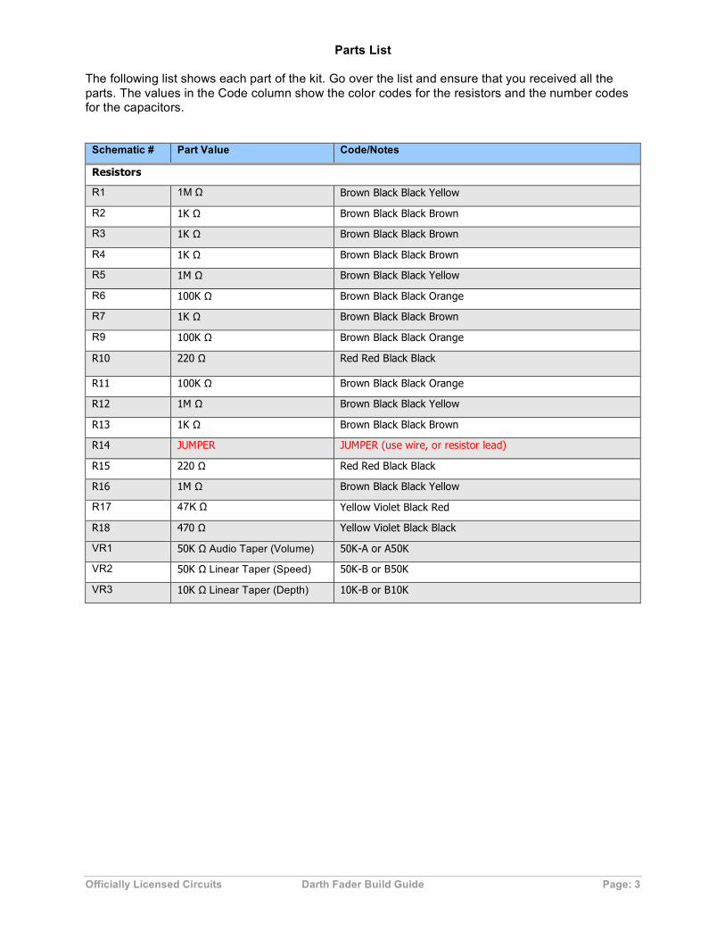
Parts List
The following list shows each part of the kit. Go over the list and ensure that you received all the parts. The values in the Code column show the color codes for the resistors and the number codes for the capacitors.
Schematic # Part Value Code/Notes
Resistors
R1 1M Ω Brown Black Black Yellow
R2 1K Ω Brown Black Black Brown
R3 1K Ω Brown Black Black Brown
R4 1K Ω Brown Black Black Brown
R5 1M Ω Brown Black Black Yellow
R6 100K Ω Brown Black Black Orange
R7 1K Ω Brown Black Black Brown
R9 100K Ω Brown Black Black Orange
R10 220 Ω Red Red Black Black
R11 100K Ω Brown Black Black Orange
R12 1M Ω Brown Black Black Yellow
R13 1K Ω Brown Black Black Brown
R14 JUMPER JUMPER (use wire, or resistor lead)
R15 220 Ω Red Red Black Black
R16 1M Ω Brown Black Black Yellow
R17 47K Ω Yellow Violet Black Red
R18 470 Ω Yellow Violet Black Black
VR1 50K Ω Audio Taper (Volume) 50K-A or A50K
VR2 50K Ω Linear Taper (Speed) 50K-B or B50K
VR3 10K Ω Linear Taper (Depth) 10K-B or B10K

Officially Licensed Circuits Darth Fader Build Guide Page: 4
Capacitors
C1 1 µF 1uF or 105 (box-looking, not electrolytic)
C2 100 nF 104
C3 1 µF 1uF or 105 (box-looking, not electrolytic)
C4 22 µf polarized electrolytic
C5 22 µf polarized electrolytic
C6 22 µf polarized electrolytic
C7 470uf or 220uf polarized electrolytic
C8 470uf or 220uf polarized electrolytic C9 1 µF polarized electrolytic C10 1 µF polarized electrolytic
C11 470 nF 474 or .47
Semiconductors
D1 1N4001
U1 TL072
Tube
V1 12AU7/12AT7/12AX7 Dual Triode
Hardware
Aluminum enclosure Hammond 1590BB style
DC jack Black plastic with chrome nut
LED Color varies with kit/order
LED bezel clip Black plastic ring with notches
LED bezel ring Black plastic ring
Heat shrink tubing (2) Insulators for LED leads
Knobs (3) Quarter inch plastic
¼” input jack
¼” input jack
Tube socket
Roll bars (2)
12 VAC adaptor For U.S. customers only

Officially Licensed Circuits Darth Fader Build Guide Page: 5
Power Supply Board Parts This list contains the parts for the separate power supply board.
C1, C2 100 µF polarized electrolytic May also be 220uF
B1 W01 Bridge Rectifier
IC2 LM7812 voltage regulator
Officially Licensed Circuits Darth Fader Build Guide Page: 6
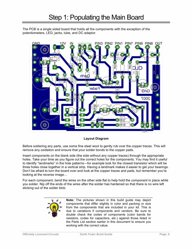
Step 1: Populating the Main Board The PCB is a single sided board that holds all the components with the exception of the potentiometers, LED, jacks, tube, and DC adaptor.
Layout Diagram
Before soldering any parts, use some fine steel wool to gently rub over the copper traces. This will remove any oxidation and ensure that your solder bonds to the copper pads.
Insert components on the blank side (the side without any copper traces) through the appropriate holes. Take your time as you figure out the correct holes for the components. You may find it useful to identify “landmarks” in the hole patterns—for example look for the closest transistor which will be three holes close together in a vertical strip. Having a landmark makes it easier to get your bearings. Don’t be afraid to turn the board over and look at the copper traces and pads, but remember you’re looking at the reverse image…
For each component, bend the wires on the other side flat to help hold the component in place while you solder. Nip off the ends of the wires after the solder has hardened so that there is no wire left sticking out of the solder blob.
Note: The pictures shown in this build guide may depict components that differ slightly in color and packing or size from the components that are included in your kit. This is due to variations if components and vendors. Be sure to double check the codes of components (color bands for resistors, codes for capacitors, etc.) against those listed in the Parts List section earlier in this document to ensure you working with the correct value.

Officially Licensed Circuits Darth Fader Build Guide Page: 7
Resistors Start with the resistors (don’t worry about the potentiometers in this step, just do the fixed resistors). Carefully check each resistor against the color band code in the parts list. You may also find it helpful to you have your digital multimeter on and set to Ohms for this step.
After you check and verify the color codes of a resistor, and before you solder them to the board, double-check the value with your meter. Note that resistors do not have polarity (i.e. there is no positive or negative side) so you can insert them in either direction.
Note that R14 should be populated with a jumper wire, not a resistor. This jumper connection can be a piece of wire or a wire leg cut off of a previously wired component.

Officially Licensed Circuits Darth Fader Build Guide Page: 8
Diode Next, install the polarity protection diode, maked D1 on on the board. This device is polarity-sensitive. Align the diode so the band on the diode matches the band shown on the PCB.
IC Socket In this step you will install the IC socket for the dual opamp integrated circuit.
Officially Licensed Circuits Darth Fader Build Guide Page: 9
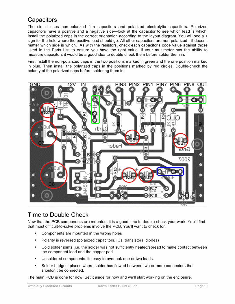
Capacitors The circuit uses non-polarized film capacitors and polarized electrolytic capacitors. Polarized capacitors have a positive and a negative side—look at the capacitor to see which lead is which. Install the polarized caps in the correct orientation according to the layout diagram. You will see a + sign for the hole where the positive lead should go. All other capacitors are non-polarized—it doesn’t matter which side is which. As with the resistors, check each capacitor’s code value against those listed in the Parts List to ensure you have the right value. If your multimeter has the ability to measure capacitors it would be a good idea to double check them before solder them in.
First install the non-polarized caps in the two positions marked in green and the one position marked in blue. Then install the polarized caps in the positions marked by red circles. Double-check the polarity of the polarized caps before soldering them in.
Time to Double Check Now that the PCB components are mounted, it is a good time to double-check your work. You’ll find that most difficult-to-solve problems involve the PCB. You’ll want to check for:
• Components are mounted in the wrong holes
• Polarity is reversed (polarized capacitors, ICs, transistors, diodes)
• Cold solder joints (i.e. the solder was not sufficiently heated/spread to make contact between the component lead and the copper pad
• Unsoldered components: its easy to overlook one or two leads.
• Solder bridges: places where solder has flowed between two or more connectors that shouldn’t be connected.
The main PCB is done for now. Set it aside for now and we’ll start working on the enclosure.
Officially Licensed Circuits Darth Fader Build Guide Page: 10
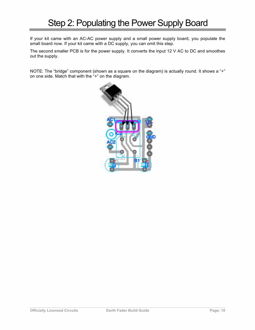
Step 2: Populating the Power Supply Board If your kit came with an AC-AC power supply and a small power supply board, you populate the small board now. If your kit came with a DC supply, you can omit this step.
The second smaller PCB is for the power supply. It converts the input 12 V AC to DC and smoothes out the supply.
NOTE: The “bridge” component (shown as a square on the diagram) is actually round. It shows a “+” on one side. Match that with the “+” on the diagram.

Officially Licensed Circuits Darth Fader Build Guide Page: 11
Step 3: Enclosure Assembly Now that you have most of the PCB done, its time to start work on the enclosure. If you ordered an un-drilled enclosure, drill the appropriate holes for the parts. If you received a drilled enclosure, you’re ready to go.
Insulating the PCB The bottom of the PCB(s) now has dozens of solder joints. You cannot allow these to come in contact with anything else in the enclosure. You must insulate the PCB(s) from the enclosure and other components.
One method is to tape a piece of cardboard (even from a cereal box) to the bottom of the PCB(s). We recommend the spongy double-sided tape that you can find at a hardware store… it is thick enough to prevent solder joints from poking through and secures your PCB in place.
Whatever you choose to do, make sure you prevent the PCB components and solder joints from shorting against the enclosure and other components in the enclosure.

Officially Licensed Circuits Darth Fader Build Guide Page: 12
Installing Parts in the Enclosure Install the jacks, 3PDT switch, LED + bezel, power adaptor and pots into the enclosure as shown below.
Note: The pictures and graphics below regarding the enclosure are shown from the perspective of looking into the back of the pedal (i.e. the screw-holes for the enclosure bottom are facing up).

Officially Licensed Circuits Darth Fader Build Guide Page: 13
Step 4: Wiring the Enclosure Hardware Now that all the parts are physically installed in the box, you can start the wiring process In this step, you’ll wire up the input and output jacks, the switch, LED, and AC adaptor connector.
You have two goals in this step: to correctly wire all the parts together exactly as shown, and to keep your wires to the minimum length necessary to fit in the box. Why short lengths? First off, shorter wires reduce noise—the longer the wire, the greater the chance that it can act as an antenna for picking up stray radio frequency or other interference. This is especially true in effects that are high gain by nature. The second reason to keep your wire lengths short is that it makes it easier to end up with a professional looking build that doesn’t have a bunch of wires compressed between pots and the boards, wires that get folded over and looped by battery, etc. Each wire also represents and opportunity for mechanical failure. Each time physical stress is put on a wire, the wire itself and the solder joints it connects to can weaken. During the build process you will be put parts in, maneuvering them around the enclosure, fixing problems, and other things.
Officially Licensed Circuits Darth Fader Build Guide Page: 14
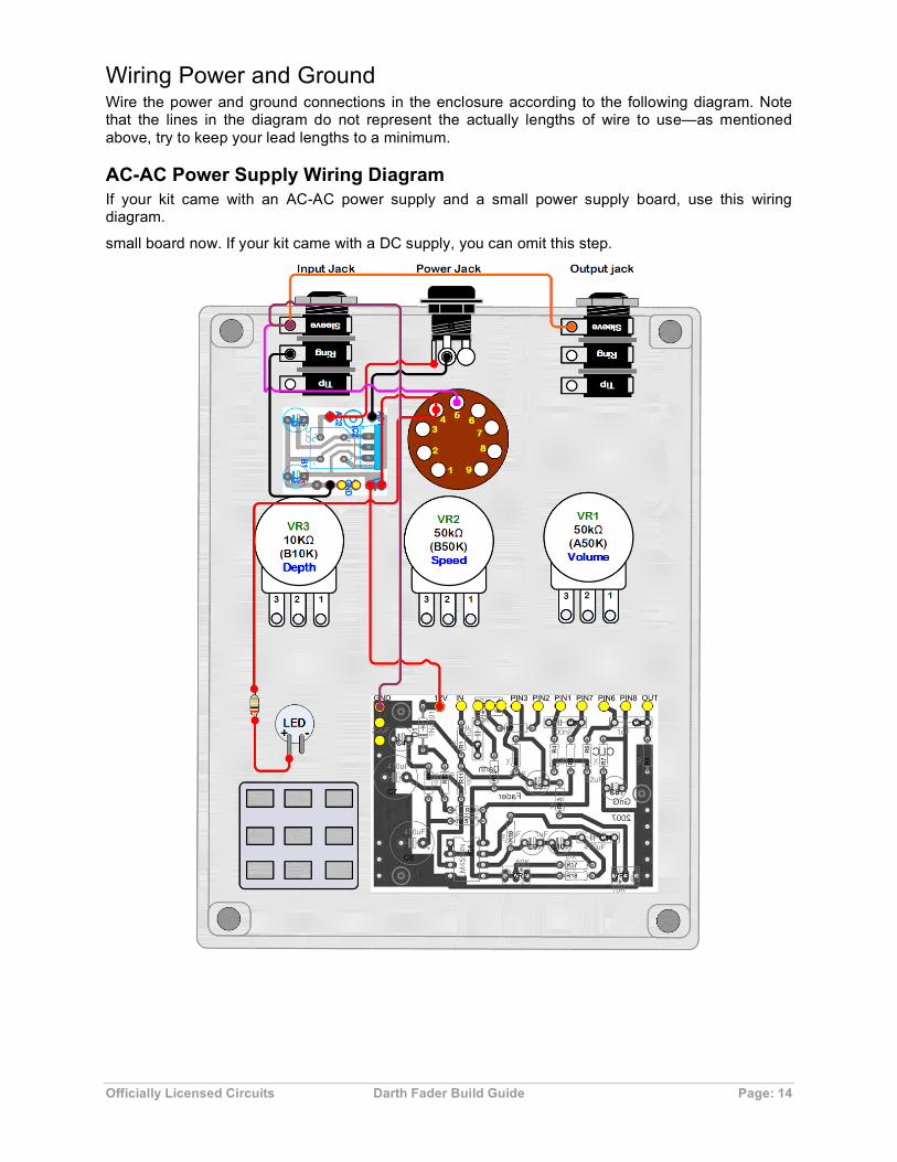
Wiring Power and Ground Wire the power and ground connections in the enclosure according to the following diagram. Note that the lines in the diagram do not represent the actually lengths of wire to use—as mentioned above, try to keep your lead lengths to a minimum.
AC-AC Power Supply Wiring Diagram If your kit came with an AC-AC power supply and a small power supply board, use this wiring diagram.
small board now. If your kit came with a DC supply, you can omit this step.

Officially Licensed Circuits Darth Fader Build Guide Page: 15
AC-DC Power Supply Wiring Diagram If your kit came with a AC-DC supply or was an non-US order, use this wiring diagram. This shows wiring for a Positive Tip/Center power supply, which is most common for power supplies available (not marketed toward guitar pedal use). If your supply is Negative Tip, simply swap the red and black diagram wires at the jack.
.

Officially Licensed Circuits Darth Fader Build Guide Page: 16
Wiring the Potentiometers In this step, you’ll wire all of the connections from the PCB to the potentiometers. Make sure you pay special attention to the pin numbers on the pots. Here are some tips for wiring pots:
To make it easier, try these tips:
1. Use a permanent marker to label the back of each pot. For example, “D” for depth, “V” for volume and so on. Be sure to check the potentiometer value before labeling them. Adding these letters can help save a world of hurt later when you realize you wired the wrong pot to the wrong part of the PCB!
2. Before wiring the pots, remove them from the enclosure.
3. Wire one pot at a time. Measure the amount of wire you’ll need to reach the board from that particular pot and leave a little excess. For your measurements, take into account whether the pot wires will need to go under the PCB or on top. (Under makes for a cleaner looking build.) Solder the three wires to the pot.
4. Before you solder the wires to the PCB, use some extra heat-shrink tubing to organize the 3-wires into bundles.
5. Take your time and work carefully when inserting the pot wires into the PCB. The PCB holes are quite small, and you want to be sure that you don’t leave any stray strands of wire sticking out on the top (non-copper) part of the board.

Officially Licensed Circuits Darth Fader Build Guide Page: 17
Officially Licensed Circuits Darth Fader Build Guide Page: 18
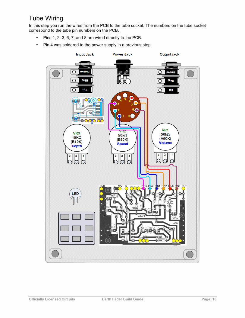
Tube Wiring In this step you run the wires from the PCB to the tube socket. The numbers on the tube socket correspond to the tube pin numbers on the PCB.
• Pins 1, 2, 3, 6, 7, and 8 are wired directly to the PCB.
• Pin 4 was soldered to the power supply in a previous step.
Officially Licensed Circuits Darth Fader Build Guide Page: 19
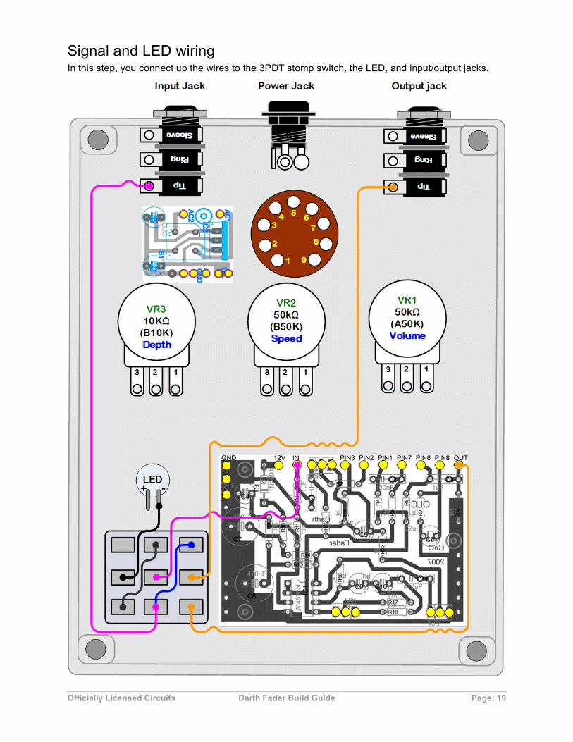
Signal and LED wiring In this step, you connect up the wires to the 3PDT stomp switch, the LED, and input/output jacks.
Officially Licensed Circuits Darth Fader Build Guide Page: 20
Before you close the case Before you close everything up, double-check your wiring once more. Also check that no exposed wires or other parts of the circuit are touching the cover as you put it on. Look for any wires that are loose, and be sure to tuck all wires neatly into the case so they don’t get caught between the case and the lid.
Install the TL072 chip into the socket—be sure the notch or dot on the chip aligns with the notch as shown on the PCB layout picture.
Officially Licensed Circuits Darth Fader Build Guide Page: 21
Step 5: Tube Time The tube in your kit is a *12AU7/ECC82 dual triode. This means that the tube has two distinct gain sections in one tube. Unlike other OLCircuits tube kits, there is no need to bias the tube in the Darth Fader.
• OLCircuits may ship 12AT7 or 12AX7 on occasion, and without notice. Your Darth Fader will perform well with any of the three types.
• You may use a different tube type than the one supplied, if you wish. The mµ, or amplification factor, from lower to higher is: 12AU7/ECC82 12AT7/ECC81 12AX7/ECC83.
Officially Licensed Circuits Darth Fader Build Guide Page: 22
Troubleshooting If you’ve done everything correctly, your pedal should work just fine. However, it is pretty rare that a DIY pedal works on the first try. There are many variables, and each one has to be addressed correctly. If your pedal doesn’t work on the first try, relax. This is typically how it goes. A little bit of troubleshooting and patience will get you there. This section lists things to check that address common mistakes.
The Obvious Stuff These are the things that are so obvious that we rarely look at them first. But they may save a lot of trouble!
• Is your guitar plugged into the input jack securely?
• Is your guitar turned up?
• Is your amp plugged directly into the output of the pedal? You should go straight into your amp for testing to eliminate the possibility that other pedals or effects/wire/power are not causing the issue.
• Do you have power? Is a battery connected? Is the battery fresh? If you are using an AC adaptor, is it plugged in?
Power • Is the pedal PCB getting power? Use your multimeter to ensure that you are getting around
9v by placing your red (+) probe on the pad that provides power (9vDC+) and any ground pad on the PCB. If you aren’t getting voltage, re-check your power wiring and connections.
• Are you using an AC Adaptor? Make sure it is a 9vDC supply and that the jack is tip-negative. Make sure it is actually plugged in and functioning by using your multimeter.
Components • Look at the PCB and the PCB Layout. Compare each value for the resistors and the
capacitors. Check off each one as you verify it.
• Make sure the transistors are oriented correctly. This is a very common problem.
• If your circuit uses polarized capacitors, make sure they are oriented correctly.
• Could an IC or transistor have wiggled out of its socket? Check all socketed components.
Wiring • Go back and double-check your wiring. Work through the diagrams shown in each step. Print
out this build guide and use your pen or pencil to place a check mark next to each wire as you verify that both ends go to the correct places.
• Visually inspect each wire to make sure that stray strands are not leading off in unwanted directions which can cause short circuits.
Officially Licensed Circuits Darth Fader Build Guide Page: 23
Soldering • You’ve done a lot of soldering in this project. There is a good chance that a bad solder joint
is causing problems. Use a magnifying glass to visually inspect the back (solder-side) of the PCB. Compare it against the PCB layout in this document. Are there any solder “bridges” that connect traces or lugs that shouldn’t be there?
• Are there connections on the PCB that look loose or non-shiny? They may need to be re-soldered.
• Also check the soldering on all the hardware parts attached to the enclosure hardware (switches, jacks, pots, etc.) Make sure that none are loose. Use your multimeter continuity feature to check each connection.
Come Back Later The longer you work on trouble-shooting in a single session, the less productive you become. Frustration can cloud your mind and dramatically reduce your innate problem solving skills.
Put your work away for a few hours or a day. Do something different. Play your guitar. Take a walk. Play with your kids. You’ll be amazed at how productive and refreshed mind can be. Remember, building pedals is about fun and learning. So you should be having fun!
Getting Help If you’ve tried the troubleshooting steps and are still having problems, please visit Officially Licensed Circuits on the web at www.olcircuits.com.
Officially Licensed Circuits Copyright © 2006-2009
www.olcircuits.com


