Karsten Heeger, Univ. of Wisconsin LBNL, August 2-3, 2011
CUORE Detector Calibration System
Karsten M. HeegerUniversity of WisconsinDetector Calibration System Leader
US CUORE Annual ReviewLBNL, August 2-3, 2011
1
Karsten Heeger, Univ. of Wisconsin LBNL, August 2-3, 2011
Outline
• Calibration system requirements• Scope and system elements• Progress at Wisconsin since 2010
– improved DCS failsafe system and positioning– integration work– system testing– hardware for 4K test– readiness and optimization for DCS fabrication – cleaning, assembly, and installation planning
• Schedule and personnel• DCS milestones and CD-4 requirements
2

Karsten Heeger, Univ. of Wisconsin LBNL, August 2-3, 2011
Calibration of CUORE Bolometers
I. Gain StabilizationFor each bolometer an energy pulse generated by a Si resistor is used to correct pulse amplitudes for gain instabilities (→ every 5 min).
III. Voltage-Energy ConversionFit of a calibration measurement with a gamma source (e.g. 232Th) of known energy. Energy calibration performed regularly. (~ monthly).
II. Calibration of individual bolometer
energy [keV]500 1000 1500 2000 2500 3000
[co
un
ts/(
ke
V k
g y
r)]
0
1000
2000
3000
4000
5000
energy [keV]500 1000 1500 2000 2500 3000
[co
un
ts/(
ke
V k
g y
r)]
0
1000
2000
3000
4000
5000
583keV 208Tl
911keV 228Ac
969keV 228Ac 2103keV
single escape
2615keV 208Tl
1592keV double escape
511keV
Sum calibration spectrum of Cuoricino with 232Th source
ββ0ν
• calibrate with γ-sources• need 5+ lines visible in calibration spectrum• energy accuracy goal: < 0.05 keV
Detector Calibration SystemProvide absolute energy calibration of energy spectrum in each bolometer
Summed spectrum from all detectors
3

Karsten Heeger, Univ. of Wisconsin LBNL, August 2-3, 2011
CUORE Detector Calibration System
need to place sources next to crystals to allow calibration of all bolometers
Key Issues• Thermal loads meet heat load requirements of cryostat• Calibration rate of < 150mHz for each bolometer to avoid pile-up• Sources can be replaced. Other source isotopes can be used if necessary (e.g. 56Co has been studied)• Shortest possible calibration time (< 1 week), minimize loss in detector livetime.• Negligible contribution to radioactive background in the ββ0ν region•Minimize the uncertainty in the energy calibration (< 0.05 keV)
Calibration uncertainty - affects the resolution of the detectors- is one of the systematic errors in the determination of the 0νββ half life
4

Karsten Heeger, Univ. of Wisconsin LBNL, August 2-3, 2011
Calibration Source Simulations
radioactive sources: 56Co and/or 232Th
56Co: proton activated Fe wire; 232Th: Thoriated Tungsten wire
both have been used in Cuoricino
~100 events over background per peak are required for successful calibration
5

Karsten Heeger, Univ. of Wisconsin LBNL, August 2-3, 2011
Calibration Source Simulations
radioactive sources: 56Co and/or 232Th
56Co: proton activated Fe wire; 232Th: Thoriated Tungsten wire
both have been used in Cuoricino
calib
ratio
n tim
e (d
ays)
Number of counts in peak
Calibration time vs counts in peak ~100 events over background per peak are required for successful calibration
5

Karsten Heeger, Univ. of Wisconsin LBNL, August 2-3, 2011
Detector Calibration System - Simulations – 06 Dec 2007
MC HEX
STILL
EXT SOURCES (symmetric)
INT SOURCES
60°
0°
Calibration Source Simulations
Optimization of Source Strength, Position, and Distribution
source positions
• achieve uniform illumination of all crystals with internal/external sources
• determine max source activity, minimize calibration time
external sources
internal sources
6

Karsten Heeger, Univ. of Wisconsin LBNL, August 2-3, 2011
Detector Calibration System - Simulations – 06 Dec 2007
MC HEX
STILL
EXT SOURCES (symmetric)
INT SOURCES
60°
0°
Calibration Source Simulations
Optimization of Source Strength, Position, and Distribution
source positions
• achieve uniform illumination of all crystals with internal/external sources
• determine max source activity, minimize calibration time
external sources
internal sources
Activity per discrete source:– internal/external sources: 130 mBq/633 mBq
– internal/external sources (top/bottom) : 131 mBq/728 mBq (higher activity to compensate for z-variation)
Max hit rate of 150 mHz per crystal to avoid pile-up, based on Cuoricino experience
layer 6
event rate in crystals (2615 keV)
6

Karsten Heeger, Univ. of Wisconsin LBNL, August 2-3, 2011
Detector Calibration System
insertion of 12 γ sources that move under own weight
vertical cross section of the cryostat
Pb shield
300K
40K
4K
0.7K80mK
10mK
detectors@ ~10mK
Pb shield
motion systeminsertion and extraction of sources in and out of cryostat
guide tubes no straight vertical access
source stringsmove under own weight in guide tubes
top view of detector array with source positions
source locations
7

Karsten Heeger, Univ. of Wisconsin LBNL, August 2-3, 2011
Detector Calibration System
insertion of 12 γ sources that move under own weight
Lead shield
40K
300K
4K
0.7K70mK10mK
guide tubes
detector support plate
bolometers@ ~10 mK
motion systeminsertion and extraction of sources in and out of cryostat
guide tubes no straight vertical access
source stringsmove under own weight in guide tubes
top view of detector array with source positions
source locations
8

Karsten Heeger, Univ. of Wisconsin LBNL, August 2-3, 2011
Cryogenic Considerations
• Calibration system must be integrated with complex detector cryostat
• Must meet available cooling power requirements at all thermal stages
→ Cooldown of source string→ Friction heat during insertion/extraction→ Static heat load of guide tubes: thermal conductance&radiation emission
Stage T [K]Cooling power
available to calibration [W]
Static heat load from
guide tubes
Radiation from source string at 4K
40K 40 – 50 ~ 1 ~1 --
4K 4 – 5 0.3 0.02 --
0.7K 0.6 – 0.9 0.55m 0.13m 0.08µ
70mK 0.05 – 0.1 1.1µ negligible 0.3µ
10mK 0.01 1.2µ 1.07µ 0.08µ
detector 0.01 < 1µ -- 0.25µ
Stainless SteelCopper
Perfect thermal coupling
Weak thermal couplinginternal external
Guide Tubes and Thermal Coupling
• Thermal conductivity of guide tubes• Radiation heat inflow from 300 K• Heat radiated by the source strings• Thermal conductivity of the source strings• Frictional heat during source string motion
40K
300K
4K
0.7K
70mK
10mK
Lead shield
Detector region9

Karsten Heeger, Univ. of Wisconsin LBNL, August 2-3, 2011
Calibration Motion System Motion Box
vacuum feedthrough with shaft
vacuum flangemotor, gears, and encoder
electrical feedthrough
drive spools can be removed with clean bag for individual source exchange
Drive Spool
source string spool
string guide
load cellhome limit switch
emergency switch
10

Karsten Heeger, Univ. of Wisconsin LBNL, August 2-3, 2011
Calibration Source & Guide Tubes
radioactive source wire•232Th: Thoriated Tungsten wire• 56Co: proton activated Fe wire
Kevlar string
PTFE heat shrink
• flexible, moves under gravity in guide tube
• small mass: < 5 grams• vertical distribution of
source activity can be adjusted
• 30 capsules crimped and evenly spaced over 85 cm of Kevlar string
Source String
Guide Tubes• stainless and/or machined from solid, low-background copper• can use teflon tubes for bends
~10mm
source wire
Cu crimp
11

Karsten Heeger, Univ. of Wisconsin LBNL, August 2-3, 2011
40K
300K
4K
0.7K70mK
10mK
Lead shield
Lead shield
Detector region
solenoid linear actuator
source string pushing blade
Magneto-mechanical 4K thermalization mechanism
12
CUORE cryostat
Thermalization at 4K Flange
Calibration Thermalization to 4K• Sources must be cooled to < 4K to meet heat load requirements• Strong mechanical contact is needed between the source carrier
and a heat sink at 4K

Karsten Heeger, Univ. of Wisconsin LBNL, August 2-3, 2011
Failsafe and Positioning Systems
Induction-based proximity sensors detects position of source capsules and counts them.
Emergency switch protects mechanically against excess tension.
Encoder measures spooling of source string.
Home limit switch provides mechanical zero position of source home position.
Gate valve closes motion box during regular data taking Failsafe during power and pressure failure, with mechanical and software switch.
Load cell measures tension in string. Allows rough position determination in cryostat. Monitors insertion and retraction. Software limits for automatic shut-off.
13
Improved Failsafe Positioning

Karsten Heeger, Univ. of Wisconsin LBNL, August 2-3, 2011
Integration Effort at Wisconsin
14
DCS Integration Effort at Wisconsin and with CUORE Integration TeamCUORE cryostat is complex
In early 2011 UWisc integrated DCS model into up-to-date cryostat model.
4 interferences above 300K:- 3 solved by rotating/customizing DCS parts- 1 solved by changing pulse tube part
cryostat model incomplete below 4K:- top support, bottom support plates missing- outdated detector frames
Frascati integration team working on many critical CUORE issues, cryostat is one of them

Karsten Heeger, Univ. of Wisconsin LBNL, August 2-3, 2011
Outstanding Integration Issues
15
Top Support Plate+DCS+Wiring Reveals InterferencesFurther integration work needed in detector region- Italian integration team proposes to change guide tube routing:original routing, proposed new routing- Monte Carlo studies of backgrounds in progress - decision by end of August 2011?
Connection to bottom plate to be finalized

Karsten Heeger, Univ. of Wisconsin LBNL, August 2-3, 2011
Calibration System TestingPhased System Testing ProgramMotion/mechanical tests at 300K extensive tests performed to date, verified and characterized motion and instrumentationcomplete but ongoing
Motion/mechanical tests at 77K tests mechanical operation of thermalization mechanism and cryostat parts for > 5 year lifetimecomplete but ongoingMotion/thermal tests at 4K (in CUORE cryostat at LNGS)hardware built for test of 1 motion box and typical guide tube routing, integrated test of thermalization, depends on CUORE cryostat schedulein preparation, planned for early 2012
16
Motion/thermal tests at 4K (standalone)- setting up independent 4K test chamber in Wisconsin (He bath and pulse tube)- tests in fall 2011
will allow UWisc to make measurements with thermalizaton mechanism and learn and prepare for 4K testing at LNGS

Karsten Heeger, Univ. of Wisconsin LBNL, August 2-3, 2011
Calibration System Testing & Schedule
17
Figure: Peterson

Karsten Heeger, Univ. of Wisconsin LBNL, August 2-3, 2011
Calibration System Testing & Schedule
17
Figure: Peterson
start of cryostat assembly = start of UWisc presence at LNGS

Karsten Heeger, Univ. of Wisconsin LBNL, August 2-3, 2011
Calibration System Testing & Schedule
17
Figure: Peterson
start of cryostat assembly = start of UWisc presence at LNGS
cryostat assembly procedure under development,expect 4K test in early 2012

Karsten Heeger, Univ. of Wisconsin LBNL, August 2-3, 2011
System Testing at Wisconsin
18
Outgassing measurements and bakingMechanical motion test stand at 300K
System tests at 77K
Setting up independent 4K pulse tube

Karsten Heeger, Univ. of Wisconsin LBNL, August 2-3, 2011
load cell
guide tubes
webcam
proximity sensor
source moves reliably under its own weightposition accuracy ~ 1-2 mmreproducible load cell pattern allows safe operation
load cell data
profile limits
load cell data shows unique geometry of guide tube system
19
up
down
Load Cell DataMechanical motion test stand at 300K

Karsten Heeger, Univ. of Wisconsin LBNL, August 2-3, 2011
Improved Positioning with Limit Switch
20
home reset switch
emergency kill switch
- Home position from encoder drifts over time by about ~2mm - home switch resets home position to increase positioning precision- engages at low force ~0.3N
Time (hrs)
Pos
ition
(cm
)drift of home position over time without home reset switch

Karsten Heeger, Univ. of Wisconsin LBNL, August 2-3, 2011
Mechanical Testing at 77K
21
Thermalization Mechanism Prototype Testing source string & capsule
thermalization blade
CUORE requirements- expect calibration ~ 1/month- 60 cycles per string over 5 years- 180 cycles per mechanism over 5 years- expect < 500 cycles including commissioning
Testing> 27000 cycles for 1 s push and 1 s release at 300K > 15000 cycles for 1 s push and 1 s release at 77K> 400 cycles for 30 s push and 30 s release at 77K > 9000 cycles for 1 s push and 1 release on top edge of blade at 77K> 800 cycles for 1 s push and 1 s release on undersized capsule at 77K
no jamming, no wear of mechanism, no significant wear on capsules
Karsten Heeger, Univ. of Wisconsin LBNL, August 2-3, 2011
Calibration System Test at 4K
22
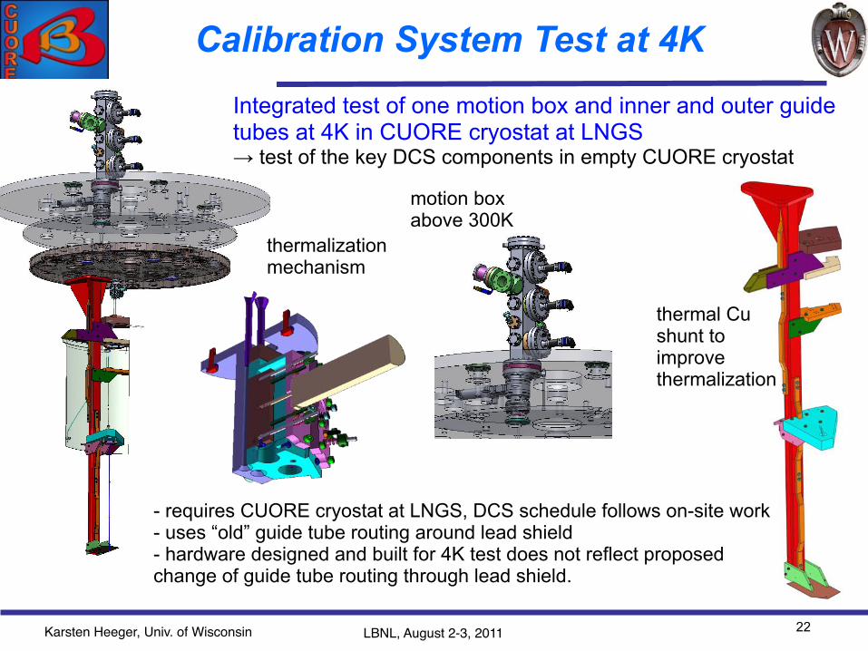
Integrated test of one motion box and inner and outer guide tubes at 4K in CUORE cryostat at LNGS→ test of the key DCS components in empty CUORE cryostat
motion box above 300K
thermalization mechanism
thermal Cu shunt to improve thermalization
- requires CUORE cryostat at LNGS, DCS schedule follows on-site work- uses “old” guide tube routing around lead shield- hardware designed and built for 4K test does not reflect proposed change of guide tube routing through lead shield.

Karsten Heeger, Univ. of Wisconsin LBNL, August 2-3, 2011
Hardware for 4K LNGS Test
23
see demonstration hardware at review
Karsten Heeger, Univ. of Wisconsin LBNL, August 2-3, 2011
Readiness for DCS Production
24
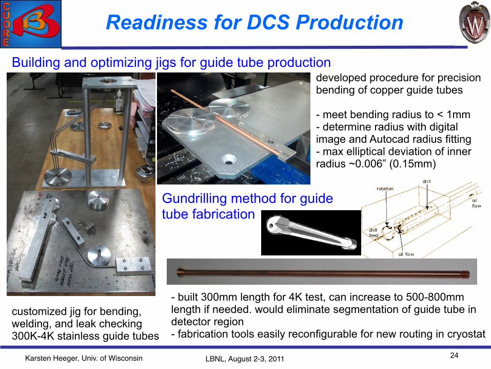
Building and optimizing jigs for guide tube production
customized jig for bending, welding, and leak checking 300K-4K stainless guide tubes
developed procedure for precision bending of copper guide tubes
- meet bending radius to < 1mm- determine radius with digital image and Autocad radius fitting - max elliptical deviation of inner radius ~0.006” (0.15mm)
Gundrilling method for guide tube fabrication
- built 300mm length for 4K test, can increase to 500-800mm length if needed. would eliminate segmentation of guide tube in detector region- fabrication tools easily reconfigurable for new routing in cryostat

Karsten Heeger, Univ. of Wisconsin LBNL, August 2-3, 2011
Cleaning and Assembly at Wisconsin
25
- New class-1000 cleanroom at Wisconsin with cleaning capabilities. Meets UHV requirements. - Will be used for source fabrication and final cleaning of motion box parts and for cleaning of DCS cryostat components. - Will be used for final acceptance testing just before shipment.

Karsten Heeger, Univ. of Wisconsin LBNL, August 2-3, 2011
Installation Planning at Wisconsin
26
1:0.75 model printout of cryostat
1:1 wooden model of cryostat flanges
300K
40K
4K

Karsten Heeger, Univ. of Wisconsin LBNL, August 2-3, 2011
Installation Planning at Wisconsin
27
1:0.75 model printout of cryostat
1:1 wooden model of cryostat flanges
300K-4K guide tubes in jig
- visualize and develop installation procedure before installation at LNGS- practice installation of guide tubes and indium seal

Karsten Heeger, Univ. of Wisconsin LBNL, August 2-3, 2011
Calibration Team
Scientists– K. Heeger (faculty)– Daniel Lenz (postdoctoral fellow, UWisc)– L. Ejzak (graduate student, 5th year)– A. Dally (graduate student, 2th year on CUORE)– S. Sangiorgio (postdoctoral fellow, now at LLNL)Engineer/Designer (UWisc)– Ken Kriesel (mechanical engineer) – Glen Gregerson (designer
28
Communication (Wisconsin and CUORE cryostat group)– weekly meetings with Wisconsin
engineer– phone meetings with cryostat
group in Milan– integration meetings at time of
collaboration meetings
Current
Planned in FY2012-13Scientists– K. Heeger (faculty)– Daniel Lenz (postdoctoral fellow, at UWisc)– A. Dally (graduate student, 2th year on CUORE) Researcher– T. Wise (senior researcher) Engineering as needed
→ on-site for DCS testing→ on-site long-term for cryostat assembly and DCS testing
→ on-site installation and testing

Karsten Heeger, Univ. of Wisconsin LBNL, August 2-3, 2011
Calibration System Milestones
29
completed
achievable if DCS 4K test at LNGS by Spring 2012
need to commit to building remaining DCS hardware in summer 2012

Karsten Heeger, Univ. of Wisconsin LBNL, August 2-3, 2011
Revised CD-4 Requirements
30
based on vacuum requirement from cryostat
Objectives for Revised CD-4 Criteria:
1. ensure DCS functionality to greatest extent possible 2. make deliverable independent of cryostat and on-site work as much as possible
Proposed Change to Calibration System CD4 Deliverables
all requirements have essentially been met with 4K test hardware

Karsten Heeger, Univ. of Wisconsin LBNL, August 2-3, 2011
Summary
• Wisconsin has completed design, mechanical tests, and vacuum testing of motion box. Developed source fabrication procedure. Continue long-term motion testing.
• Built hardware for 4K calibration test in cryostat at LNGS. • Optimizing fabrication procedures for remaining DCS hardware.• Addressing outstanding integration challenges together with
CUORE integration team in Italy. Will finalize DCS integration in detector region in Fall 2011.
• Develop independent capabilities at Wisconsin for cleaning, assembly, and mechanical and thermal testing of DCS components to greatest extent possible.
• Developing installation plans and procedures utilizing 1:1 model of cryostat at Wisconsin.
31

Karsten Heeger, Univ. of Wisconsin LNGS, March 28-29, 2011
`
32


