Contributions of US Fusion Materials Programto ITER Test Blanket Modules
S.J. Zinkle, on behalf of the US fusionmaterials researchers
ITER Test Blanket Module meeting
UCLA, March 2, 2005

Assessment of structural materials issues for ITERTBMs•New versions of the FM steels F82H and Eurofer with
improved toughness and radiation performance are evolving
•Multiple fabrication stages and thermo-mechanical treatmentsrequired to construct TBMs will affect final microstucture andpossibly impact in-service mechanical behavior
•The planned US/Japan 15J/16J HFIR irradiation experimentprovides a good approximation to TBM irradiation conditions(300C,400C, 2.5-5dpa)
•Possibility of including advanced versions of the FM steels andspecimens derived from prototypic fabrication cycles areunder discussion with JAERI

FY05 R&D activities• ITER materials R&D
–High strength Cu alloy assessment and neutron irradiation R&D–Complete critical assessment of ITER materials properties
handbook data–Support US PFC activities–Support ITER US plasma diagnostics activities–Initiate plasma heating materials R&D (loss tangent of ceramic
insulators)–Participate in plasma diagnostics ITPC workshops (watching
brief on radiation effects and experimental artifacts)• ITER TBM materials R&D
–Structural materials (ferritic/martensitic steels)–Functional materials (SiC flow insert, barrier coatings)
• US/Japan (Jupiter-II and DOE-JAERI) collaboration• Cross-cutting theory and modeling

Dose at start of loading: 8.6 x 10⁻⁴
dpa
Dose at start of loading: 1.1 x 10⁻²
dpa
Dose at start of loading: 1.8 x 10⁻⁵
dpa
Dose at start of loading: 2.9 x 10⁻⁵
dpa
CuC
rZr
OFH
C C
uOptical Microstructure of neutron-irradiated Cufollowing in-situ straining
Specimen fracture occurs without ductile necking(irradiation assisted stress corrosion cracking?)
EU-US collaborationB.N. Singh, D.J. Edwards, S. Tähtinen, P. Moilanen, P. Jacquet and J.Dekeyser, Risø-R-1481(EN), to be submitted, Nov. 2004
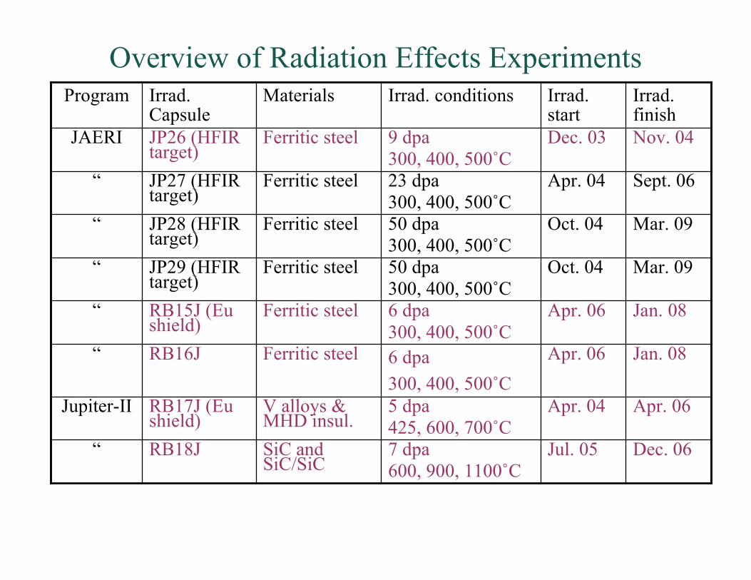
Overview of Radiation Effects Experiments
Dec. 06Jul. 057 dpa600, 900, 1100˚C
SiC andSiC/SiC
RB18J“
Apr. 06Apr. 045 dpa425, 600, 700˚C
V alloys &MHD insul.
RB17J (Eushield)
Jupiter-II
Jan. 08Apr. 066 dpa300, 400, 500˚C
Ferritic steelRB16J“
Jan. 08Apr. 066 dpa300, 400, 500˚C
Ferritic steelRB15J (Eushield)
“
Mar. 09Oct. 0450 dpa300, 400, 500˚C
Ferritic steelJP29 (HFIRtarget)
“
Mar. 09Oct. 0450 dpa300, 400, 500˚C
Ferritic steelJP28 (HFIRtarget)
“
Sept. 06Apr. 0423 dpa300, 400, 500˚C
Ferritic steelJP27 (HFIRtarget)
“
Nov. 04Dec. 039 dpa300, 400, 500˚C
Ferritic steelJP26 (HFIRtarget)
JAERI
Irrad.finish
Irrad.start
Irrad. conditionsMaterialsIrrad.Capsule
Program

Low Temperature Radiation Hardening is Important inFusion RAFMs up to ~400˚C
0
200
400
600
800
1000
1200
0 0.05 0.1 0.15 0.2 0.25 0.3 0.35
USJF82Hss2
En
gin
ee
rin
g S
tre
ss,
MP
a
Engineering Strain, mm/mm
Representative USDOE/JAERI F82H Data:200-600°C, 3-34 dpa
Unirradiated YS
200°C/10 dpa
250°C/3 dpa
300°C/8 dpa
400°C/10 dpa
400°C/34 dpa
500°C/8 dpa
500°C/34 dpa
600°C/8 dpa
Tirr
=Ttest
J.P. Robertson et al.,(DOE/JAERI collaboration)

Engineering stress-strain curves of 9Cr-2WVTa ferritic/martensitic steel after irradiation in spallation environments
Low uniform elongation occurs after irradiation to 0.6 dpa at low temperatures

(a)
(b)
0
200
400
600
800
1000
0 5 10 15 20 25 30
F82H IEA Std.
En
gin
eeri
ng
Str
ess
(MP
a)
Engineering Strain (%)
Irrad. at 573KTested at RT
Irrad. 773KTested at RT
Irrad. 773KTested at 773K
Irrad. at 573KTested at 573K
0
200
400
600
800
1000
0 5 10 15 20 25 30
F82H IEA TIG
En
gin
eeri
ng
Str
ess
(MP
a)
Engineering Strain (%)
Irrad. at 573KTested at RT
Irrad. at 573KTested at 573K
Irrad. at 773KTested at 773K
Irrad. at 773KTested at RT
Fig. 1 Stress-strain curves of F82H BM (a) and TIG (b)
irradiated at 573K and 773K in tests at RT
F82H BM
F82H TIG
Deformation microstructures in neutron-irradiatedFe-8Cr-2WVTa ferritic/martensitic steel (F82H)
Slip plane: (110) and (011)Slip direction: [111] and [111]
Dislocation channels
Deformation band
N. Hashimoto et al., Fus.Sci.Tech. 44 (2003)
B ≈ [111]g = 110
110
500nm100nm
110
Irradiated weld metal (lower radiation hardening) did notexhibit dislocation channeling after deformation
5 dpa
5 dpa
F82H base metal
F82H TIG weld

Dislocation channel interactions in Fe deformed followingneutron irradiation at 70˚C to 0.8 dpa
g.b.
Need well-engineered materials tomitigate neutron radiation effects
Clearedslipchannel

Master Curve Shifts (ΔTo) and He Effects• Modeled irradiation hardening (Δσy)
induced ΔTo ≈ 0.6°C/MPa• Peak hardening up to ≈ 600 MPa =>
large ΔTo => To ≥ 250°C.• Spallation proton data suggests at > 600-
800 appm He weakens grain boundariesproducing very brittle intergranularfacture that interacts synergistically withΔσy.
• Estimates of combined effects suggestTo > 500°C possible - clearly a showstopper
• High concentrations of H may also bedamaging
0
100
200
300
400
KJc
(M
Pa!
m)
-200 -100 0 100 200
T (°C)
F82H - SINEXT
Unirr. MC
Model
Unirr. - Cor.
Unirr.
Irr. MC
Irr. - 5 mm
Irr. - 10 mm
235°C
0
100
200
300
!T
o (
°C)
0 100 200 300 400
!"y (MPa)
!T/!"y = 0.57 (°C/MPa)
F82H !"y est.
T91
F82H
RPV
b.
Model
≈ 0.6°C/MPaRPVmodel
lowerstrain
hardening
model
0
100
200
300
KJc
(T)
(MP
a!m
)-250 0 250 500 750
T (°C)
!"y He/IGF
operatingrange
J. Henry et al., JNM 318 p.215J. Henry et al., JNM 318 p.249 G.R. Odette, UCSB

Overview of Improved Steels• Steels can exhibit a wide range of properties depending on detailed
composition and thermomechanical treatment• Four generations of ferritic steels based on materials science
principles have been commercialized (R. Viswanathan, Adv. Mater.& Processes 162, No. 8 (2004) 73)– 1st generation 1960-1970; 2nd generation 1970-1985; 3rd generation 1985-
1995; 4th generation currently emerging
• Fusion 9Cr ferritic/martensitic steels are based on “2nd Generation”steels developed around 1985; fusion steels are comparable to 3rdgeneration commercial steels– Fusion substitution of W for Mo (reduced activation) was also pursued for “3rd
generation” commercial steels
• Future steel development options will likely be based on evolutionary(ingot metallurgy/ classical precipitation) and revolutionary(nanoscale oxide dispersion strengthening) approaches

Ferritic/martensitic Steels with Reduced Radioactivity andSuperior Properties Compared to Commercial Steels havebeen Developed by Fusion
Developmentalreducedactivation steels
IEA fusionreducedactivationsteel
Commercialferritic steel(HT9)
Fusion-developed steels also have superiortensile strength, irradiated fracturetoughness, and thermal conductivity
Comparison of thermalcreep-rupture strengths
10-7
10-6
10-5
10-4
10-3
10-2
10-1
100
1 10 100 1000 104
Comparison of Fission and Fusion Radioactivity after Shutdown
Cu
rie
s/W
att
(T
he
rma
l P
ow
er)
Years After Shutdown
Fission: Light Water Reactor
Fusion: Conventional Ferritic steel
Fusion: Reduced Activation
Ferritic Steel
Coal AshBelow Regulatory Concern

Modified Thermomechanical Treatment Procedure forNew 9Cr Ferritic/Martensitic Steel Produced HighStrength
• Strength and ductility intensile test are comparableto high-strengthexperimental ODS steel
R.L. Klueh, to be published

Low-Cr Bainitic Steels Originally Developed by Fusion asReplacement for Commercial 2 1/4 Cr-1Mo Steel
• Low-chromium steels have advantages– Better weldability for easier plant fabrication—an important consideration
• May not require post-weld heat treatment– Cheaper because of less chromium
• Previous studies at ORNL discovered effect of heat treatment ontype of bainite formed
• Mechanical properties determined by type of bainite formed• Discovery was used to develop 3Cr steels
– 50% increase in tensile strength compared to conventional 2 1/4 Cr-1Mo steel– Improved fracture toughness behavior
0
200
400
600
800
1000
0 100 200 300 400 500 600 700
Comparison of the Yield Tensile Strength
of New 3 Cr Steel and 2 1/4 Cr Steel
0.2
% Y
ield
Str
en
gth
(M
Pa
)
Temperature (˚C)
New alloy
Current alloy
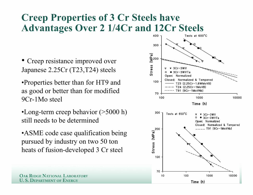
Creep Properties of 3 Cr Steels haveAdvantages Over 2 1/4Cr and 12Cr Steels
• Creep resistance improved overJapanese 2.25Cr (T23,T24) steels
•Properties better than for HT9 andas good or better than for modified9Cr-1Mo steel
•Long-term creep behavior (>5000 h)still needs to be determined
•ASME code case qualification beingpursued by industry on two 50 tonheats of fusion-developed 3 Cr steel

Creep Properties of 3 Cr Steels haveAdvantages Over 2 1/4Cr and 12Cr Steels
• Creep resistance improved overJapanese 2.25Cr (T23,T24) steels
•Properties better than for HT9 andas good or better than for modified9Cr-1Mo steel
•Long-term creep behavior (>5000h) still needs to be determined
•Two 50 ton heats have beenfabricated to initiate ASME codeapproval

Oxide dispersion strengthened Steels• There are two main options for ODS steels
– Ferritic ODS steel (typically 12-16%Cr)– Ferritic/martensitic ODS steel (typically ~9%Cr)
Limited to temperature below~700 CMarginal oxidation resistance athigh temperatures
Nearly isotropic propertiesafter heat treatmentBetter fracture toughness
9% ODSferritic/martensiticsteel
Anisotropic mechanicalpropertiesLower fracture toughness
Higher temperature capabilityBetter oxidation resistance
12-16% ODSferritic steel
DisadvantagesAdvantagesSteel

0
200
400
600
800
1000
1200
400 600 800 1000 1200
Temperature (K)
12YWT
MA956
ODS (SUMITOMO)
9Cr-2WVTa
ODS(ZrO2)
ODS(TiO2)
ODS(MgO)ODS(Al
2O
3)
Yie
ld S
tress
(M
Pa)
New 12YWT Nanocomposited Ferritic Steel hasSuperior Strength compared to conventional ODS steels
O Y Ti10 nm
• Atom Probe reveals nanoscale clustersto be source of superior strength
– Enriched in O(24 at%), Ti(20%), Y (9%)– Size : rg = 2.0 ± 0.8 nm– Number Density : nv = 1.4 x 1024/m3
• Original Y2O3 particles convert tothermally stable nanoscale (Ti,Y,Cr,O)particles during processing
• Nanoclusters not present in ODS Fe-13Cr + 0.25Y2O3 alloy
• Thermal creep time to failure is increased byseveral orders of magnitude at 800˚Ccompared to ferritic/martensitic steels
• Potential for increasing the upper operatingtemperature of iron based alloys by ~200°C
• Acceptable fracture toughness near roomtemperature

Nanocomposited ODS Steel Summary• Fundamental understanding of the formation of nanoclusters (NCs)
and uniform grain sizes in Fe-14Cr ferritic alloys has been achieved– Advanced characterization tools utilized to study effects of composition,
processing conditions at key steps in fabrication process• Small Angle Neutron Scattering (SANS)• Energy Filtered Transmission Electron Microscopy (EFTEM)• Local Electrode Atom Probe (LEAP) field ion microscope
• The thermal stability of nanoclusters in several ODS steels has beenstudied– Results suggest remarkable nanocluster stability (e.g., particles are resistant to
coarsening at 1000ºC for up to t > 105 h)• Preliminary results showed essentially no changes in the size or
structure of the nanoclusters in 12YWT ODS steel following 6.8MeVFe+3 irradiation to 20 dpa at 700ºC
• PIE of ODS ferritic alloys in HFIR JP26 (5-8 dpa, 300-500˚C) will bestarting– Variety of ODS ferritic alloys (MA957, PM2000 and 12YWT, etc.)– Microstructural effects of fusion-relevant He injection during irradiation

Local Electrode AP Revealed High a Number Densityof Nanoclusters in the As-Extruded 14YWT Alloy
• The nanoclusters are consistent with Y-, Ti- and O-enricments• LEAP also shows C associated with the NC’s
• A possible grain boundary shown in the atom map is enriched with Y,Ti, and O atoms
• Segregation of Cr and W to the grain boundary was also observed• Annealing the as-extruded alloy at 1000 º C for 1 h showed no
changes in the NC’s
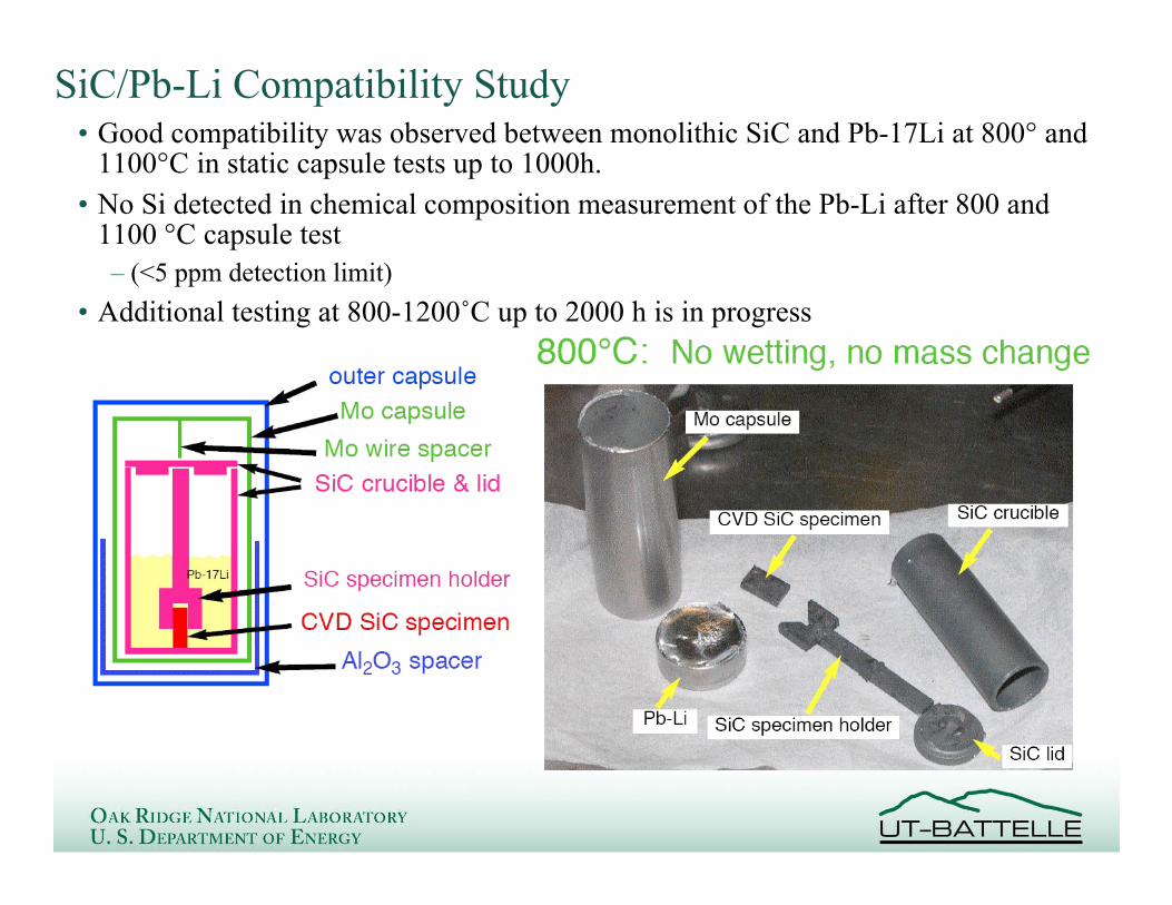
SiC/Pb-Li Compatibility Study• Good compatibility was observed between monolithic SiC and Pb-17Li at 800° and
1100°C in static capsule tests up to 1000h.• No Si detected in chemical composition measurement of the Pb-Li after 800 and
1100 °C capsule test– (<5 ppm detection limit)
• Additional testing at 800-1200˚C up to 2000 h is in progress
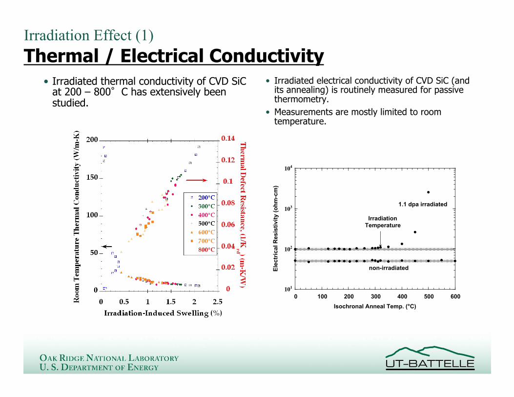
Irradiation Effect (1)Thermal / Electrical Conductivity
• Irradiated thermal conductivity of CVD SiCat 200 – 800 C has extensively beenstudied.
101
102
103
104
0 100 200 300 400 500 600
Ele
ctr
ical R
esis
tivit
y (
oh
m-c
m)
Isochronal Anneal Temp. (°C)
1.1 dpa irradiated
non-irradiated
IrradiationTemperature
• Irradiated electrical conductivity of CVD SiC (andits annealing) is routinely measured for passivethermometry.
• Measurements are mostly limited to roomtemperature.
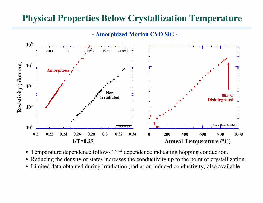
Physical Properties Below Crystallization Temperature- Amorphized Morton CVD SiC -
102
103
104
105
106
0.2 0.22 0.24 0.26 0.28 0.3 0.32 0.34
Res
isti
vit
y (
oh
m-c
m)
1/T^0.25
Amorphous
NonIrradiated
0°C -100°C -200°C-150°C200°C
Low-T res s-10
0 200 400 600 800 1000
Anneal Temperature (°C)
885°CDisintegrated
Anneal Figure ResistivityTirr
• Temperature dependence follows T-1/4 dependence indicating hopping conduction.• Reducing the density of states increases the conductivity up to the point of crystallization• Limited data obtained during irradiation (radiation induced conductivity) also available

10-10
10-9
10-8
10-7
10-6
10-5
10-4
10-3
10-2
10-1
100
101
10-2 10-1 100 101
Elec
trica
l Con
ducti
vity
(S/m
)
Dose Rate (Gy/s)
x x x x x x x
Kyocera ! SiC, 22°C
Kyocera ! SiC, 200°C
Hexoloy SiC, 22°C
CVD SiC, 22°C
Hexoloy non-irradiated
+ +Nicalon
Nicalon non-irradiated
+++++σ=σo+KRδ
Radiation Induced Conductivity for different grades of SiC:Electrical Conductivity varies by 8 orders of magnitude!
• Ionizing radiationexcites electrons intothe conduction bandenhancing conductivity.
• If unirradiatedconductivity is high, RICis insignificant
Doserate
L.L. Snead, J. Nucl. Mater.329-333 (2004) 524
All values measured to date are <2 S/m

HFIR-18J will examine transport properties of SiC andSiC/SiC composites for FCI applications
(Planned)~103Tyranno™-SA Grade-3
PlannedPlannedCVI Composites, Type-S orSA3, varied PyC interphases
(Planned)~103Hi-Nicalon™ Type-S
Planned0.05<0.005CVD SiC Low Conductivity
PlannedPlanned10~1CVD SiC Standard
PIE, ThermalConductivity
PIE, ElectricalConductivity
ElectricalConductivity
(S/m)
NitrogenConcentration
(ppm)
• The 18J experiment enables a reliable prediction of the irradiated electrical andthermal conductivities for various SiC-based materials by the constitutivemodeling approach.
US/Japan Jupiter-II collaboration

10
100
0 100 200 300 400 500 600 700 800
Th
erm
al C
on
du
ctiv
ity
(W
/m-K
)
Measurement Temperature (°C)
Rohm Haas CVD SiCORNL Data
Non-irradiated
4.5 dpa/800°C
4.0 dpa/500*C
4.6 dpa/300°C
0.001
0.01
0.1
1
0.0001 0.001 0.01 0.1 1 10
dpa
Th
erm
al D
efec
t R
esis
tan
ce (
W/m
-K)-1
ORNL Data
200°CComposite
200°CCVD SiC
800°CComposite
800°CCVD SiC
!
K (T )[ ]"1
=1
Ku(T )+
1
Kgb(T )+1
Kd 0
+1
Krd
#
$ %
&
' (
umklapp boundaries intrinsicdefects
radiationdefects
Thermal Defect Resistance Model Enables ReliablePrediction of Irradiated Thermal Conductivity ofComposites

Thermal Conductivity of 2D SiC/SiC Composites
0
20
40
60
80
100
0 200 400 600 800 1000 1200
Th
erm
al
co
nd
uc
tiv
ity
(W
/mK
)
Temperature (°C)
2D-SA Tyrannohex
(unirradiated)
(50% parallel fibersand 50% interfaces)
(100% transverse fibersand 100% interfaces)
0
10
20
30
40
50
0 200 400 600 800 1000 1200
Temperature (oC )
Th
erm
al
Co
nd
uc
tiv
ity
(W
/mK
) fiber: Tyranno SAmatrix: CVI-SiC
Vf = 0.4
(enhanced f/m bonding)
(degraded interface)
(typical interface)
5000
500
50
Interface
conductance(W/cm
2K)
0
10
20
30
40
50
400 600 800 1000 1200
Temperature, K
Th
erm
al
Co
nd
uc
tiv
ity
, W
/mK fiber: Tyranno SA
matrix: CVI-SiCV
f = 0.4, t = 200 nm
(anisotropic PyC)
(isotropic PyC)
(degraded PyC)
20 W/mK
0.2 W/mK
2.0 W/mK
Coating
Conductivity
• Number and quality of interfacesimportant
• Fibers parallel to conduction pathuseful (3D architecture)
• Samples currently being irradiated
Experimental:
NERI Program
• Strong bonding due to fibersurface treatment useful
• Degraded interface due toirradiation or fiber/matrixmismatch
Model 1: Thin Interface Conductance• Preferred orientation of
graphitic crystallites• Strong interface cohesion• Degraded interphase due to
irradiation or oxidation
Model 2: Interphase Conductivity
Fusion Materials Program
U.S. Department of EnergyPacific Northwest National Laboratory


